
APPENDIX A (Small Force Mains List) · Kaneohe Bay # 2 Kaneohe Bay # 3 Kaneohe Bay # 4 Kaneohe Bay...
53
APPENDIX A (Small Force Mains List)
-
Upload
nguyennhan -
Category
Documents
-
view
218 -
download
0
Transcript of APPENDIX A (Small Force Mains List) · Kaneohe Bay # 2 Kaneohe Bay # 3 Kaneohe Bay # 4 Kaneohe Bay...
APPENDIX A (Small Force Mains List)

Aala Drive Alala Point Aliamanu # 1 Aliamanu# 2 Alii Bluffs Coconut Grove Enchanted Lake Ewa Gentry Grandview Halekou Heeia Homelani Acres Kahaluu Kahaluu Housing Kahanahou Kahawai Stream Kahuku Effluent Kaneohe Bay # 2 Kaneohe Bay # 3 Kaneohe Bay # 4 Kaneohe Bay South #5 Kemoo Farm Kukanono Kuliouou Laie Lakeview Circle Leanani Makakilo Maunawili Estates Maunawili Park Mililani Miomio MoanaPark N akula Street Nanakuli Ohai Place Pacific Palisades Paiko Drive Public Baths Punawai Sand Island Industrial Park
APPENDIX A
Small Force Mains «1.3 MGD Average Daily Flow)
Sand Island Parkway Uwalu Waiawa Industrial Park Waikalua Waikapoki Waipio West Beach Resort #1 West Beach Resort #2 West Loch Estates West Loch Fairways
APPENDIXB (Large Force Mains List)

Ahuimanu Ala Moana Awa Street Beachwalk EwaBeach Fort DeRussy Halawa Hart Street Kahala Kailua Heights Kailua Road Kamehameha Highway Kaneohe Bay #1 Kaneohe-Kailua Kunia Lualualei Niu Valley Pearl City - East Pearl City - West Waimalu Waipahu - East Waipahu - West
APPENDIX B
Large Force Mains (::0:1.3 MGD Average Daily Flow)

APPENDIXC (Site-Specific Spill Contingency Plan)

APPENDIXC
Site Specific Spill Contingency Plan
The purpose of the Spill Contingency Plan is to establish measures and procedures to respond to a force main spill event in order to minimize discharges to surface waters, to prevent public exposure to the spilled wastewater, and to retun} the force main to full service as rapidly as possible. The Spill Contingency Plan must be: (1) specific to the location; (2) prepared in accordance with good engineering practices; and (3) be readily accessible so that it is a source of usable information for employees or response personnel during an actual emergency.
The contents of the Spill Contingency Plan shall include: Force Main Information; Response Procedures; Equipment, Parts, and Supplies; and Plan Updates. The contents are described as follows:
Force Main Information
This section of the Spill Contingency Plan shall contain salient information about the force main, including, location, diameter, length, material, elevations, design flows and pressures, fittings, parallel force mains, location of stonn drain inlets and waterways, and a vicinity map of the force main, including nearby gravity sewers and pump stations that may be used for diversion of flows in the event the force main is damaged.
Schematic diagrams shall be included, depicting all valves, access points, and fittings that may be used in an emergency response to contain or divert sewage from the damaged force main.
This section of the Plan shall also describe monitoring and/or alarms at the force main (or its associated pump station) including, but not limited to, SCADA that could serve to notifY CCH of a potential spill.
Spill Response
This section of the Spill Contingency Plan shall include a list of the actions that CCH anticipates taking in the event of a force main spill -- including tankering and diversion of flows within the system using parallel force mains or other facilities. This section shall describe the personnel CCH will have available to deploy in the event of a force main spill, the staff notification procedures, and anticipated response times.
This section of the Plan shall include a list of steps that CCH anticipates taking to minimize discharges from the force main to surface waters including, but not limited to, procedures for shutting down pumps, diversion of sewage to parallel force mains or nearby gravity sewers, spill containment, tankering, emergency discharge locations (to be used only if no other practicable contingencies exist), and notification to industrial/ commercial dischargers and residential customers in the service area to minimize water usage.
1

This section of the Plan shall inclnde the steps that CCH anticipates taking to notifY impacted agencies and the public of the location and size of the force main spill. It shall also include plans for warning members of the public in order to prevent public exposure to spilled wastewater, including, but not limited to, posting procedures.
This section of the Plan shall include the methods CCH anticipates using to clean up and mitigate the impacts of the spill. Procedures for the decontamination of spills sites and disposal of contaminated water, soil, equipment, and supplies shall be included.
Equipment, Parts and Supplies
This section of the Plan shall include a list of the equipment, parts and supplies needed to support the Plan including response and repair equipment, spare parts, and supplies that can be used in the event of a force main failure. The response equipment shall include portable pumps, hose or piping, sand bags (or equivalent barrier/diversion devices) and pipe plugs. The supplies shall include replacement pipe, valves and repair kits. The list shall identifY the location of all such equipment, parts, and supplies.
Plan Updates
CCH shall review the Spill Contingency Plan annually, and shall revise the Spill Contingency Plan as necessary to address any pertinent changed conditions and to ensure the functionality ofthe key components of the Plan; provided however, such revisions shall not eliminate any element of the Spill Contingency Plan required by this Appendix.
CCH shall provide a copy of any revised Spill Contingency Plan to EPA and DOH.
2

APPENDIXD (Force Main Condition Assessment)
APPENDIXD
Force Main Condition Assessment
1. OBJECTIVES
A. Conduct assessments of a force main for the purpose of locating conditions that may cause pipe leakage, failure or interruption of service, In determining the appropriate assessment methods, cost alone is not a basis for rejecting or selecting an assessment method, but is a factor to be considered in selecting from among appropriate assessment methods,
B, Conduct inspections of all accessible valves, fittings, and appurtenances associated with the force main for the purpose of locating conditions that may cause pipe leakage, failure or interruption of service,
C, For each inspection, document the findings of each condition discovered,
D, Assess the risk of pipe failure associated with each condition discovered,
E. Gather sufficient information on the force main to detem1ine the appropriate course of action so that the force main can continue to function (either as a primary or back-up force main) without a material risk of failure,
F, Provide a plan with schedules for addressing each condition that poses a material risk of pipe failure or service interruption, Follow-up actions may include monitoring the situation, preventative maintenance, repair, rehabilitation or replacement.
II. SCREENINGIPRELIMINARY RISK ASSESSMENT
A. Evaluate Previous Failures - Evaluate past force main failures, determine the likelihood of repeat failures, and identify portions of the force main at risk for a repeat failure,
B. Prior Condition Assessments - Evaluate past condition assessments and identify pOltions of the force main at risk of failure or in need of further assessment.
C. High Risk Pipe Configuration - Review force main plans to identify piping configurations at increased risk of failure including connections, joints and bends,
D. Identify Corrosion Risks - Identify locations along each pipeline that are at risk for corrosion of the intemal or extemal pipe walls, CCH shall employ the
1

best available screening methods suitable for the force main, including, but not limited to, the following:
I. Identification of pipeline high points.
2. Identification of locations with failed cathodic protection, if installed.
3. Measurements of pipe-to-soil electrical potential.
4. Soil resistivity testing.
5. Examination of force main discharge manholes for signs of corrosion indicating cOlTosi ve wastewater.
E. Right-Of-Way Inspection - Inspect pipeline right-of-ways to look for signs of pipe damage or physical changes that may affect the condition of the force mam. Right-of-way inspections shall include, but not be limited to, the following:
I. Examination of soils adjacent to pipelines to look for wet spots, unusual vegetation growth or other indications of lealcage.
2. Observations of recent construction or road repairs that may have affected the structural integrity of the force main.
3. Observations ofland movements (slides, rock falls, sink holes, settling) that may have affected the structural integrity ofthe force main.
4. Observations of other conditions, such as unusual surface loads, that may have affected the structural integrity of the force main.
III. ASSESSMENTS
A. Valves, Fittings and Appurtenances - Inspect and conduct functional analyses of, to the extent practicable, all valves, air-relief valves, drains, cormections, fittings and appurtenances associated with the force main. Identify each valve, fitting or appurtenance that is not fully functional or functioning as intended. Identify conditions that present a material risk of pipe failure or intelTUption of service of the force main.
B. Cathodic Protection - Evaluate the integrity and adequacy of all installed cathodic protection systems. Identify each location where the protection has failed or where protection is inadequate. If cathodic protection is not installed on a force main, evaluate whether conditions warrant the installation of cathodic protection.
2

C. External Pipe Inspections
1. Locations - The exterior of the force main shall be inspected at:
a) Each location where the pipe is exposed; and
b) Each location determined to present a material risk offailure or interruption of service based on the screening analyses pursuant to section II (excavation may be necessary to reach these locations).
2. Inspection Methods
a) At each location identified pursuant to section III. C.l above, the pipe exterior shall be visually inspected for structural damage and the integrity of protective coatings.
b) Additional inspections shall be conducted as needed to locate and assess pipe conditions that present a material risk of pipe failure or interruption of service. Special attention shall be focused on locations determined, pursuant to section ILD above, to present a material risk of pipe corrosion.
c) The exterior of the force main shall be inspected using visual inspection and/or the best proven teclmology that is suitable to the particular pipe to identify conditions such as cracks, corrosion, erosion, or coating damage/delamination that pose a material risk of pipe failure or interruption of service. Best proven teclmology may include ultrasonic examination of pipe walls or pipe wall samples, or other methods for determining the extent of pipe corrosion.
D. Internal Pipe Inspections - Internal pipe inspections shall utilize the best proven inspection technology that is suitable to the particular pipe to identify conditions, such as cracks, corrosion, erosion, coating de-lamination, joint deflections, pipe deformation and debris accumulation, that pose a material risk of pipe failure or interruption of service. Internal force main inspections shall be conducted on the length of pipe that is practically accessible with the selected inspection method. At a minimum, CCH shall inspect the portions of pipe necessary to identify or characterize conditions that pose a material risk of pipe failure or interruption of service, including, but not limited to, all high points in the pipes, to the extent practicable. Where practicable, CCH shall conduct evaluations in the vicinity of all access points (air relief valves, discharge manholes and other valves and fittings that provide access). If any portion of a force main is not subjected to internal inspection, CCH shall provide an explanation in the final assessment report.
3

E. Operating Pressnre Evaluations - The City shall evaluate the operating and transient pressure for the force main. The purpose of the evaluation is to determine if the design, construction, and materials are sufficient to withstand the maximum predicted transient pressures that may be expected to occur under normal, peak flow, and emergency (shut-down and start-up) conditions. This evaluation shall include, but not necessarily be limited to, a review of available pressure sensor data (SCADA and strip chart_ to evaluate nonnal operating pressures, and an evaluation, using transient pressures models or actual pressure measurements, of the transient pressures that occur during the range of anticipated operating conditions. Any actual pressure measurements shall be limited to the range of operating conditions that is both prudent and practicable.
F. Leak Detection - The City shall follow up on observed conditions that are likely to be the source of leakage. The methodologies employed will be appropriate to the type of condition and location of the suspected leakage.
IV. CONDITION ASSESSMENT REPORTS AND -ACTION PLANS
A. Assessment Methods - Describe the method and extent of each assessment conducted under section III, including valve, fitting and appurtenance inspections; cathodic protection evaluations; external and internal pipe inspections; operating pressure evaluations and leak detection tests. Describe each external and intemal pipe inspection method utilized and the locations, including the length of pipe, where each method was employed. Provide justifications for the selection of inspection methods and locations. In an appendix to the report, provide a copy of the original field data.
4

B. Assessment Results and Findings
1. Assessment Results
a) Describe the results ofthe screening/preliminary risk assessments conducted pursuant to section II, including a listing of the pipe segments identified as having a material risk of pipe failure or interruption of service based on corrosion potential or other factors.
b) Describe the results of each assessment conducted under section III, including valve, fitting and appurtenance inspections; cathodic protection evaluations; external and internal pipe inspections; operating pressure evaluations and/or leak detection tests.
2. Findings of Conditions - Identify and quantify (where practicable) observed or measured conditions that constitute a material risk of pipe failure or service interruption. In describing such conditions, characterize the nature of the risk of failure associated with the condition, the likelihood and imminence (to the extent practicable) of the failure risk and the consequences should such a failure occur. The conditions to be addressed in this report may include:
a) Pipe conditions: cracks, holes, corrosion, erosion, coating delamination, joint deflections, pipe deformation and debris accumulation;
b) Valve, fitting and appurtenance conditions;
c) Cathodic protection system conditions; and
d) Leaks.
C. Follow-up Action Plan - Provide a proposed action plan to address conditions that constitute a material risk of pipe failure or service interruption as a primary or back-up force main. The action plan shall include, but not be limited to: 1) maintenance plan, 2) schedule for future assessments, 3) schedule for design and construction of repairs, rehabilitation, improvements or replacement as applicable. In developing the action plan, CCH shall consider what actions are necessary to achieve the objectives set forth above in Section I.
5

APPENDIXE (Force Main Operation and Maintenance Program)
FORCE MAIN
OPERATION AND MAINTENANCE PLAN
May 11,2010

TABLE OF CONTENTS
1, PURPOSE""", """""""""""""""""""""""""""""""""""""""""""""""" ,1
2, ABBREVIATIONS" ",' '"'''''''' """""'" ""'"'''''''''''' '''' "" ""','" ,,,,,,,,,,,,,,,,,,,,,,, "'" ,,1
3, RESPONSIBILITIES "'" "'''' """"""""'''''''' "'"'' ''', "" "" """"'"'' ",1
4, O&M PROGRAM ELEMENTS"""" """"""""""""""""""",,2 , 4,1,
4.2,
4,3,
4.4,
4,5,
Surface Marking,
4,1.1, Buried Force Mains 4,1.2, Underwater Force Mains" 4,1,3, Exposed Force Mains" .
Location Information. "","",,"'" 4,2,1, Design Phase. "" 4,2,2. Construction Phase.""" ' 4.2,3, Inspection during Construction""
Performance Testing"
Operational Inspections"
'" 2 ,2
",2 ,,2
." 2 ,2
. ",," "" 2 "" 3
",,",",," "",,3
""" 3 4.4,1, Force Main Right-of-Way, 4.4,2, Air and Vacuum Relief Valves """""""'" 4.4.3. Isolation (Inlet) and Blow-Off Valves" 4.4.4, Significant Rainfall Event... """""""""'"
". "",," 4 ""'"'''''''''''''''''''''''''''' 4
"'''",,'''' 5 '" ", ""'" 6
4.4.5, Corrosion Protection".", 4.4,5.1. Electrolysis Test Stations ",," 4.4,5,2. Passive Corrosion Protection Systems" 4.4,5,3. Active Corrosion Protection Systems,
4.4.6, Pipe and Discharge Manhole/Structure Condition"
Pump Station/Force Main System Operations" """.,,"'" 4,5,1, Sulfide Monitoring. 4,5,2, Pump Stations with Single Force Mains, ",,' ," "'" 4.5,3, Pump Stations with Multiple Force Mains"
4,5.3,1, Dry Weather"""""""", ." 4,5.3,2, Wet Weather",
6 "" 6
"".,,"'" ,6 "" 6 ,,7
,,7
""'" 7 "'" 7 "'" 7
.7 """'" 8
5, EMERGENCY OPERATIONS AND EMERGENCY RECOVERY FEATURES """'"'''' ,,""" 8
5.1, All-Weather Access to Valves, Pressure Manholes and Discharge Manholes/Structures". """"""'''''' ",8
5,2, Pressure Manholes"" """ , "". '" " """.,,",,'
6, MAINTENANCE,,,,, '" "" '" "" ,," ",,' "'"'''''' ",' "" ''',,,' '" ,,'" '" "," ""''''''
6,1, Predictive Maintenance"""",
City and County of Honolulu Foree Main O&M Plan
,8
'''''''' 9 .,,9
May II, 2010 Pagei

6.2.
6.3.
6.4.
6.5.
Table 1:
Preventive Maintenance 6.2.1. Air and Vacuum Relief Valves. 6.2.2. Isolation and Blow-off Valves. 6.2.3. Corrosion Protection System ................. . 6.2.4. Force Main Cleaning.
Corrective Maintenance.
Reactive Maintenance ...
Spare Parts ..
LIST OF TABLES
Responsibilities.
. ... 9 . .. 9
. ..... 9 . ........ 9
..9
.10
. ......... 10
. ...... 11
.1
Table 2: Summary of Force Main Operational Inspections and Frequencies ........ 3
City and County of Honolulu Force Main O&M Plan
Mayll.2010 Page ii

1. PURPOSE
The purpose of this Force Main Operation and Maintenance (O&M) Plan is to provide a listing of the progran1s and activities that CCH wiD employ to minimize the frequency and severity of SSOs that result from force main failures. Comprehensive details of the Performance Testing, Operational Inspections, and Predictive Maintenance are described in the individual pump station O&M manuals and the WTD Directives. This plan is subject to modification based on changes in field conditions and industry equipment standards. Inspection frequencies will increase or decrease depending on the equipment's condition when inspected.
2. ABBREVIATIONS
The following abbreviations are used in tIns plan.
CCH CSM DDC DPP ENV fps gpm MGD O&M SD SRE SSO WD WTD
3.
City and County of Honolulu Collection System Maintenance Division Department of Design and Construction DepaJ1ment of Planning and Pel111itting DepaJ1ment of Envirorunental·Services Feet per second Gallons per minute Million gallons per day Operation and MaintenaJ1ce Site Development Division Significant Rainfall Event SaJ1itary Sewer Overflow Wastewater Division Division of Wastewater Treatment and Disposal
RESPONSIBILITIES
The responsibilities for implementing the elements ofthis plan are shown on Table 1.
Table 1: Responsibilities
City and County of Honolulu Force Main O&M Plan
~~~
May 11, 2010 Page 1

4. O&M PROGRAM ELEMENTS
4.1. Suriace Marking
The purpose of force main marking is to prevent inadvertent damage to force mains caused by excavation, dlilling and other underground construction activities.
4.1.1. Buried Force Mains The location of all buried force mains will be identified using surface markers at least every 100 feet. The markers will read:
• Caution • Buried Sewage Pipe under Pressure. • Call WTD Operations at (808) 847-8307 before digging
4.1.2. UndelWater Force Mains The entry and exit points for all underwater force mains will be identified using surface markers. The markers will read:
• Caution • Submerged Sewage Pipe under Pressure • Call WTD Operations at (808) 847-8307 before working in vicinity
4.1.3. Exposed Force Mains The location of all exposed force mains will be identified using markers at least every 100 feet. The markers will read:
• Caution • Sewage Pipe under Pressure • Call WTD Operations at (808) 847-8307 if any problems
4.2. Location Information
4.2.1. Design Phase CCH - DPP/Site Development Division will notify designers regularly working in the service area that Trenching Pennits are required for any earthmoving, drilling, excavation, or other underground construction.
4.2.2. Construction Phase
Contractors are required to obtain a Trenching Pennit from DPP for any ealthmoving, drilling, excavation, or other underground construction. The contractor will notify DDC within seven days of pennit approval of any nearby force main facilities.
City and County of Honolulu Force Main O&M Plan
May 11,2010 Page 2
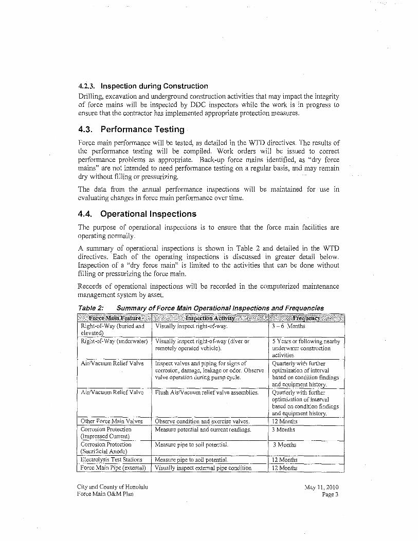
4.2.3. Inspection during Construction Drilling, excavation and underground construction activities that may impact the integrity of force mains will be inspected by DDC inspectors while the work is in progress to ensure that the contractor has implemented appropriate protection measures.
4.3. Performance Testing
Force main performance will be tested, as detailed in the WTD directives. The results of the performance testing will be compiled. Work orders will be issued to correct perfonnance problems as appropriate. Back-up force mains identified, as "dry force mains" are not intended to need performance testing on a regular basis, and may remain dry without filling or pressurizing.
The data from the annual performance inspections will be maintained for use in evaluating changes in force main performance over time.
4.4. Operational Inspections
The purpose of operational inspections is to ensure that the force mam facilities are operating nOlmally.
A summary of operational inspections is shown in Table 2 and detailed in the WTD directives. Each of the operating inspections is discussed in greater detail below. Inspection of a "dry force main" is limited to the activities that can be done without filling or pressurizing the force main.
Records of operational inspections will be recorded in the computerized maintenance management system by asset.
Table 2: Summary of Force Main Operationaiinspections and Frequencies
AirNacuum Relief Valve
City and County of Honolulu Force Main O&M Plan
activities Quarterly with fwiher optimization of interval based on condition findings and
i optimization of interval based on condition findings and
May 11, 2010 Page 3

where exposed. Force Main Pipe (internal) Visually inspect internal pipe condition at 12 months
discharge location. Dissolved Sulfides in Force Sample and analyze force main effluent for 12 Months Main Effluent total dissolved sulfides or gaseous Hydrogen
Sulfide.
Pipe Protective Coating Determine protective coating integrity by 12 Months inspecting pipe visually and using a paint thickness gauge. Analyze predictive maintenance data. 12 Months
4.4.1. Force Main Right-of-Way The force main inspection consists of a detailed and methodical visual inspection of each force main right-of-way to identify loss of support, earth movement, condition of features (e.g., pressure manholes), nearby construction activities, early signs of leakage, vandalism or other conditions that could lead to a force main failure. The inspections will be conducted by walking the force main right-of-way for buried and elevated force mains and by a diver or remotely operated vehicle for underwater force mains. The results will be recorded in an inspection log that notes both locations and observations. Any significant or unusual situations will be recorded using photographs.
4.4.2. Air and Vacuum Relief Valves The air and vacuum relief valve inspection will consist of a detailed and methodical visual and operational inspection to identify whether the valves are functioning, that they are not leaking, that they are in serviceable condition and that they are adequately protected from damage. The visual and operational inspection will include cycling the valves manually and observing the valves in operation during a normal pwnping cycle (pump stop, idle time and start). The isolation valves that are used to shut off the air and vacuum relief valves will be operated at the time of the inspection to verify that they operate properly. See Table 2 for intervals.
The air relief valve discharge will be directed into a container when the valve is manually cycled to contain any sewage that may be discharged. The results will be recorded in an inspection log that notes both locations and observations. Any significant or unusual situations will be recorded using photographs.
The employee inspecting the valves would be in contact with an operator at the pump station who would cycle the pumps and communicate their status to the inspector.
The volume that is discharge when an air/vacuum reIiefvalve is flushed is dependent on h' d f alve. The volume for one flushing cycle is: t e size an type a v
Size Volume (inchest (gallons)
2 5 3 6 4 9 6 20
City and County of Honolulu Force Main O&M Plan
May 11,2010 Page 4
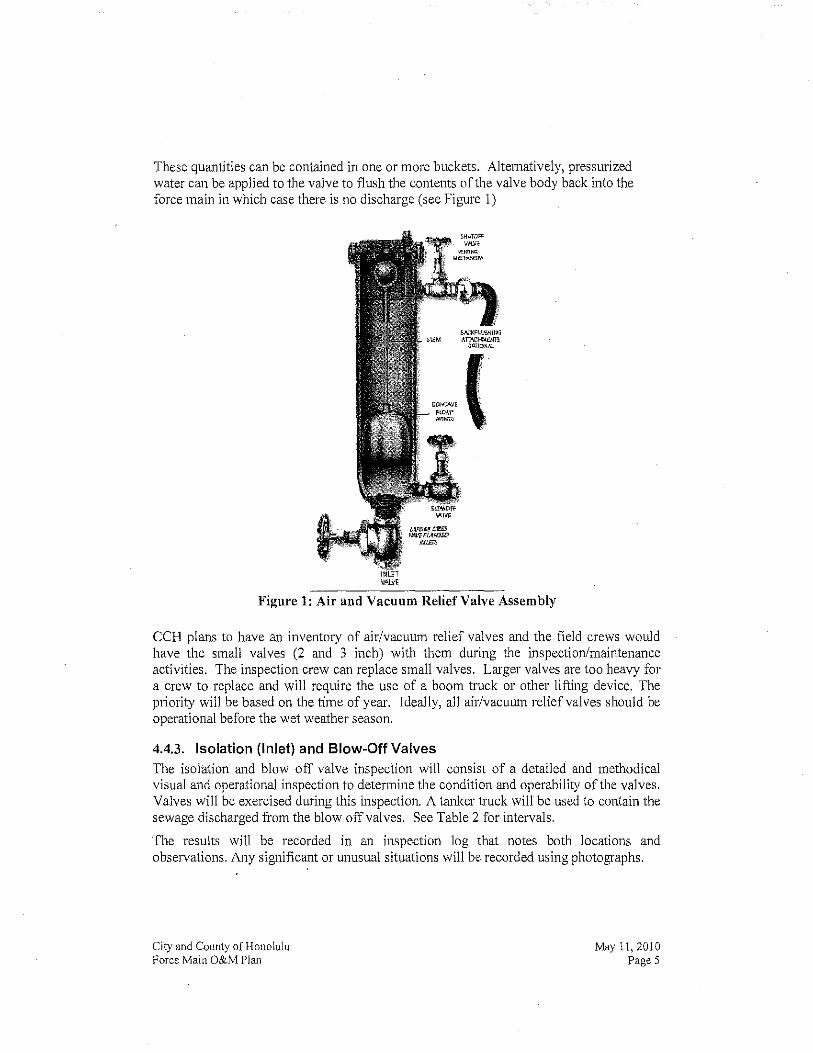
These quantities can be contained in one or more buckets. Alternatively, pressurized water can be applied to the valve to flush the contents of the valve body back into the force main in which case there is no discharge (see Figure I)
".oN", (I ... pU:Wr' ~~o .
Figure 1: Air and Vacuum Relief Valve Assembly
CCH plans to have an inventory of air/vacuum relief valves and the field crews would have the small valves (2 and 3 inch) with them during the inspection/maintenance activities. The inspection crew can replace small valves. Larger valves are too heavy for a crew to replace and will require the use of a boom truck or other lifting device. The priority will be based on the time of year. Ideally, all air/vacuwn relief valves should be operational before the wet weather season.
4.4.3. Isolation (Inlet) and Blow-Off Valves The isolation and blow off valve inspection will consist of a detailed and methodical visual and operational inspection to determine the condition and operability of the valves. Valves will be exercised during this inspection. A tanker truck will be used to contain the sewage discharged from the blow off valves. See Table 2 for intervals.
The results will be recorded in an inspection log that notes both locations and observations. Any significant or w1Usual situations will be recorded using photographs.
City and County of Honolulu Force Main O&M Plan
May 11,2010 Page 5

4.4.4. Significant Rainfall Event The significant rainfall event (SRE) inspections will be conducted by WTD Pump Station persoID1el and consist of a detailed and methodical visual inspection to detennine the condition of force mains where their reliability may be impacted by saturated soil conditions and/or heavy surface runoff. SRE inspections will be focused on specific collection system facilities. A SRE is defined as a rainfall event associated with a Flood Waming announcement. These inspections will be conducted in areas where rainfall has OCCUlTed within 48 hours after the end of the rainfall event. The results will be recorded in an inspection log that notes both locations and observations. Any identified corrective actions required will be initiated through a Corrective Action Work request within the computerized maintenance management system.
4.4.5. Corrosion Protection The potential for corrosion and the functioning of the corrosion protection systems will be inspected as per Table 2. Corrective actions such as adjusting cun'ent settings, activating spare anodes, repair, and corrosion protection system replacement will be perfonned under the WTD's material maintenance management program. The procedures for the inspections follow:
4.4.5.1. Electrolysis Test Stations
The pipe-to-ground potential for metallic force mains with electrolysis test stations will be measured according to Table 2.
The results will be recorded in an inspection log that notes both locations and observations. Any significant or unusual situations will be recorded using photographs. The results will be reviewed by a qualified engineer or technician or by a qualified corrosion-engineering consultant to evaluate the data.
4.4.5.2. Passive Corrosion Protection Systems
Passive corrosion protection systems employ sacrificial anodes. The pipe-to-ground potential will be measured according to Table 2.
The results will be recorded in an inspection log that notes both locations and observations. Any significant or unusual situations will be recorded using photographs. The results will be reviewed by a qualified engineer or technician or by a qualified cOlTosion-engineering consultant to evaluate the data.
4.4.5.3. Active Corrosion Protection Systems
Active corrosion protection systems employ impressed currents. The pipe-to-ground potential and the system current will be measured according to Table 2.
The results will be recorded in an inspection log that notes both locations and observations. Any significant or unusual situations will be recorded using photographs. The results will be reviewed by a qualified engineer or technician or by a qualified cOlTosion-engineering consultant to evaluate the data.
City and County of Honolulu Force Main O&M Plan
May I I, 2010 Page 6

4.4.6. Pipe and Discharge Manhole/Structure Condition The pipe and discharge manhole/structure inspection will consist of a detailed and methodical visual inspection to determine the condition of the exposed portions of the force main and the condition of the discharge manhole/structure. The inspection will be conducted either visually or with the aid of mirrors and/or down-hole camera systems. The inspection of the exposed portions of the force main will include observations on the condition ofthe coating system.
The results will be recorded in an inspection log that notes both locations and observations. Any significant or unusual situations will be recorded using photographs. The results will be reviewed by a qualified engineer or technician or by a qualified COlTosion-engineering consultant to evaluate the data.
4.5. Pump Station/Force Main System Operations
The pump station/force main systems will be operated as described below.
4.5.1. Sulfide Monitoring Force main effluent dissolved sulfides or effluent structure atmospheric hydrogen sulfide concentration will be measured as per Table 2.
The results will be recorded in a log that notes time, date, flow and total dissolved sulfide/atmospheric hydrogen sulfide concentration. The results will be reviewed by a qualified engineer or technician or by a qualified cOlTosion-engineering consultant to evaluate the data. Results will be recorded in the computerized maintenance management system by asset.
4.5.2. Pump Stations with Single Force Mains Pump stations with single force mains will be operated in a manner to produce a high velocity to flush accumulated solids once per week. Tbe desired flushing velocity is 3 feet per second (fps).
4.5.3. Pump Stations with Multiple Force Mains Pump stations with multiple force mains will be operated in a manner to produce a high velocity to flush accumulated solids in the operational force main once per week (force mains are altemated periodically). The desired flushing velocity is 3 fps. Back-up force mains identified as "dry force mains" are not intended to need flushing or testing on a regular basis, and may remain dry without filling or pressurizing.
4.5.3.1. Dry Weather
During dry weather periods, these pump stations will nonnally be operated with one force main in service (if the force main capacity is adequate to handle dry weather flows). Force main operation will be altemated every week so each is flushed at least evelY other week. The transition from one force main to the other should be gradual in order to minimize potential downstream odor issues.
City and County of Honolulu Force Main O&M Plan
May I I, 2010 Page 7

4.5.3.2. Wet Weather
During wet weather periods, all force mains may be operated when required to avoid collection system spills. During this situation, each of the force mains will be flushed once per week. During force main flushing, the flow will be diverted to one of the force mains for the day shift or as long as possible given the flow conditions at the time.
5. EMERGENCY OPERATIONS AND EMERGENCY RECOVERY FEATURES
Emergency operations will be undertaken in the event of a force main failure. The emergency operations may include some of the following activities as deemed appropriate and as may be more particularly described within site specific spill contingency plans or contained in individual pump station O&M manuals:
• Shut down the pump station and store flows in the wet well and upstream collection system;
• Transfer flows to parallel force main, if available; • Drain the force main to minimize the quantity ofthe spill; • Contain spilled sewage to the extent feasible; • Effect emergency repairs using stored repair clamps and/or pipe sections; • Employ specialty contractors to suppOJ1 CCH forces during the emergency; • Employ pump truck operations to remove wastewater from the wet well and
dispose of the wastewater at an approptiate location; and/or • Pump around the force main break to convey the flow until repairs are complete.
In addition to these emergency operations activities, force mains will be provided with the following emergency recovery features:
5.1. All-Weather Access to Valves, Pressure Manholes and Discharge Manholes/Structures
Gravel or paved access within the City'S right-of-way will be constructed where approptiative to allow O&M persOJU1el and/or vehicles to have all-weather access to install temporary pumps and piping, to replace/repair valves and to repair exposed sections of the force main. Location maps are located in the respective individual pump station O&M manuals.
5.2. Pressure Manholes
Pressure manholes will be installed as needed on new and rehabilitated force mains approximately every 1,000 feet to allow for the installation of pump-around equipment and/or to provide access for intemal inspection.
City and County of Honolulu Force Main O&M Plan
May 11, 2010 Page 8
6. MAINTENANCE
The pump station/force main systems will be maintained as described below. Records of maintenance activities will be recorded in the computerized maintenance management system by asset.
6.1. Predictive Maintenance
The data from force main right-of-way inspections, pipe and discharge manhole/structure inspections and effluent sulfide monitoring will be used to focus the predictive maintenance progranl. Predictive maintenance will include periodic evaluations of pipe and structure coating systems and pipe wall thickness.
The results will be recorded in an inspection log that notes both locations and observations. Any significant or unusual situations will be recorded using photographs. The results will be reviewed by a qualified engineer or technician or by a qualified engineering consultant to evaluate the data.
Work orders will be issued to COITect identified problems as appropriate.
6.2. Preventive Maintenance
The force main preventive maintenance program will include the following activities.
6.2.1. Air and Vacuum Relief Valves The results of the air and vacuum relief valve operational inspections will be used to establish the appropriate preventive maintenance frequency for flushing and rehabilitating/replacing the valves. The initial inspection frequency is listed in Table 2 and the frequency adjusted based on the field data.
6.2.2. Isolation and Blow-off Valves The results of the isolation and blow-off valve operational inspections will be used to identify valves that require maintenance, repair, rehabilitation or replacement.
6.2.3. Corrosion Protection System The results from tbe corrosion protection system inspections will be used to establish the approptiate preventive maintenance frequency for tbe active corrosion protection systems and for replacing tbe anodes in the passive corrosion protection systems. The initial frequency will be 12 months for the active cOHosion protection system.
The results fi-om the pipe and discharge manhole/structure inspections will be used to establish the preventive mainten811ce fi-equency for the pipe 811d manhole/structure coating systems.
6.2.4. Force Main Cleaning Force main cle811ing will be accomplished using pigging, swabbing, or other appropriate methods.
City and County of Honolulu Foree Main O&M Plan
May 11,2010 Page 9
Other methods of cleaning a force main include flushing with high flows or flushing with a high velocity sewer cleaner. The term swabbing includes forcing a loose fitting device through the force main (e.g. a coarse sand bag filled with ice). The term pigging includes forcing a pig through the force main.
The results from the Periodic Pump Station Performance Testing will be used to establish the preventive maintenance frequency for cleaning the force mains serving medium and large pump stations (medium pump stations are pump stations equal to or greater than 2 mgd but less than or equal 30 mgd in design capacity; large pump stations are pump stations that have a design capacity greater than 30 mgd). Force mains serving small pump stations with a rated capacity of less than 2 MGD will be cleaned every five years.
6.3. Corrective Maintenance
Planned repairs to force mains will be completed within the work order priority timeframe. Force mains that require frequent or significant repairs due to their condition will be considered for rehabilitation or replacement. Force main rehabilitation or replacement will be based on the repair history of the asset and will consider the replacement costs of the asset. Contractors will be employed to assist CCH staff when necessary to complete cOlTective maintenance.
The WTD priority system is: • Priority I (EmergencylRegulatory ViolationlLife Threatening/Safety
o Emergency o Complete Immediately o Overtime is authorized
• Priority 2 (Urgent) o Emergency o Complete As-Soon-As-Practical with pre-approved work order o Overtime requires pre-approval
• Priority 3 (Predictive or Routine Maintenance) o Pre-determined frequency under work order system o Complete within 30 days
• Priority 4 (Col1'ective Maintenance) o Planned work order o Complete within 3 months
• Priority 5 (Special Projects/System Modifications) o Low priority maintenance or improvements o Complete within I year
6.4. Reactive Maintenance
Unplalmed repairs to force mains will be completed within the work order priority timeframe as shown in Section 6.3. Corrective Maintenance. Contractors will be employed to assist CCH staff when necessary to complete unplanned repairs.
City and County of Honolulu Force Main O&M Plan
May 11,2010 Page 10
6.5 Spare Parts
Spare pipe, valves, and repair couplings will be stocked to support timely completion of maintenance, repairs, and emergency response. These spare palis, as per the O&M manual spare parts list, site specific spill contingency plans and pump station O&M manuals will be stocked at appropriate nearby locations and managed under the WTD material management program.
City and County of Honolulu Force Main O&M Plan
May 11. 2010 Page 11

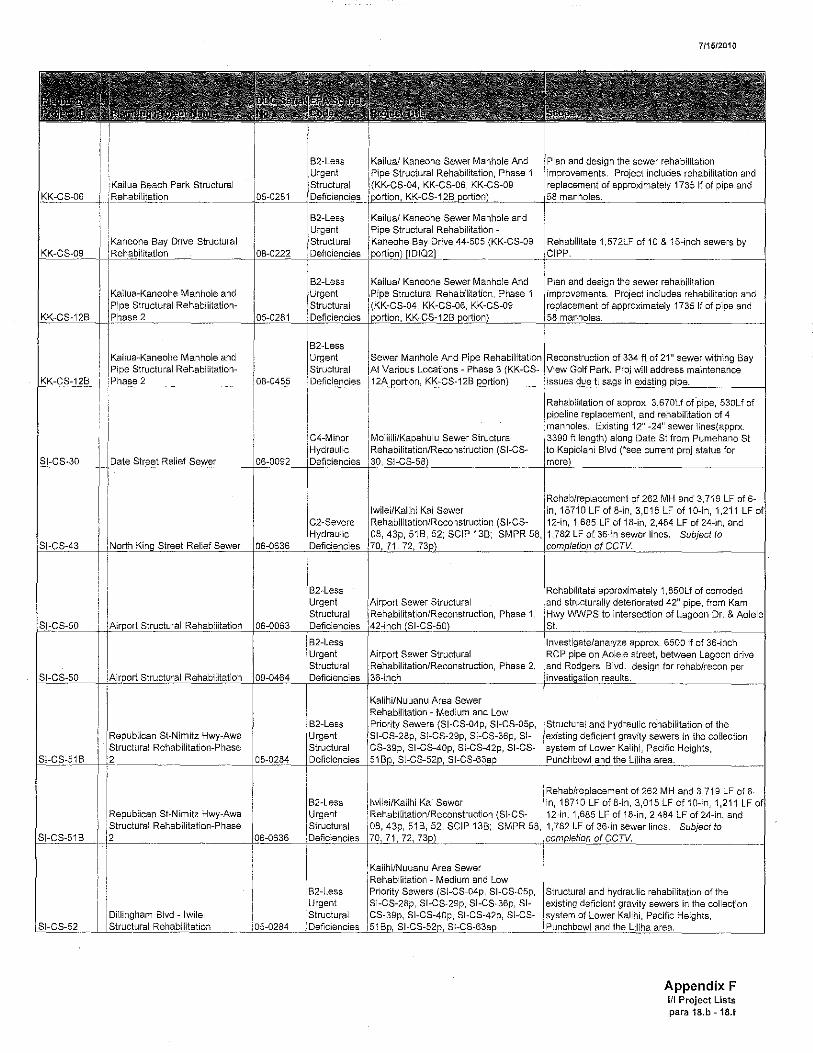
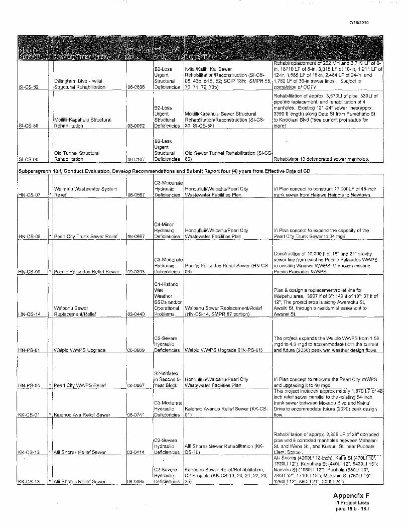
APPENDIXF (Scope of the 1999 Final Sewer III Plan Projects)

A
, ,
II I i I Sewer
Island Basin Misc IStrur,",,'1 Rehabilitation - Phase
Waimalu Sewer
Enchanted Lake WV'JPS
S1. Structural
St. Structural
C2-Severe
Ii
I ~::~::~i~~~;~ Area Sewer I F Medium and Low (SI-CS-04p, SI-CS-05p,
ISI-I~S-:'8p, SI-I~S-:'9p" SI-CS-36p, SISI-I;S-,40p, SI-CS-42p, SI-CS-
Area Sewer I I
I ~''''nIlNuuanu Area Sewer Medium and Low (SI-CS-04p, SI-CS-05p,
ISH~S-:28p, SI-I~S-:29p" SI-CS-36p, SISI-CS-4(lp, SI-CS·-42p, SI-CS-
'Hc,"ouillil JIIII \fWI/TP Upgrade Phase 1
i Er1Ch"ntl,d Lake WVlfPS Upgrade (KK-
711512010
lotrucwr,,, and hydraulic rehabilitation of the i gravity sewers in the collection
Lower Kalihi, Pacific Heights, iii
Structural and hydraulic rehabilitation of the deficient gravity sewers in the collection
Lower Kalihi. Pacific Heights, Iii
HN-CS-'13 Waimalu Sewer Rehab/Recon 7DOIC (aka Waimalu Sewer Rehab Phase II) reconstruct 920 LF of ~I PVC sewer, 309 LF of 12" PVC
Construction of eight items: grit/pre-aeration tank lallerationlS, rehab IPS wei well MH and extend I ",twalKs, overflow weir at splitter box, repair roadways, repair concrete on 5 existing bldgs, replace AC waterline, and irrigation system
modifications under this project will increase I of th,e eXisting Enchanted Lake
The Enchanted Lake WWPS Was found undersized based on hydraulic modeling, a high rate of infiltration and inflow in the
. Proj limits extend from Pacific st.
Appendix F If I Project Lists para 18,b - 18,f

! I ,
4
I Moana Blvd-24 Structural
Moana Blvd-36 Structural
Moana Blvd-i6 Structural
i Structural Rehabilitation 04-11
Wahiawa WWfP Influent Pump Station Upgrade and
Waimanalo Sewer iii
SSOs and/or Operational
S1-lnitiated
no later than December
C2-Severe Mililani \NINPTF Storage and Hydraulic
C1-Historic
Rer,abilitati'Jn/F:ecc,nstructi'on (SI-CS-
Kuliouou Sewer Rehabilitation and WNPS Modifications - Wl/VPS
il I
Waimanalo Sewer Rehabilitation (VVI\II-CS-02 I I
711512010
Ala
I Plan"inq and design services to address nY'Jrau""1 structun,'defects in sewer lines along Ala Boulevard between Ward Avenue and
box.
Rehabilitation of 11,415 Lf of 6, 8 and 12-inch sewer by CIPP and 178 laterals. Installation of 150 If of new PVC
Install new grinder channels and grinders, new screens, new air diffusers, new blowers,
beds, yard piping and ancillary
i Rehabilitate and replace approximately 10,800 ; L.F. of sewerline in three locations for hydraulic
.. _ .... _.. __ ;~~structiJral·~~·······_· __ ····___1
i Kalanianaole Highway Sewer Relief &
il I
St (SI-CS-38), School SI (SI& Um! SI (SI-CS-37) Relief
IR'~h'~i:::;:;a;:n~~d replace approximately 10,800 ! l in three locations for hydraulic
Appendix F III Project Lists para 18.b - 18.f

711512010
St (SI-CS-38), School St (SI-& Umi St (SI-CS-37) Relief Rehabilitation of 830 LF of 15-inch pipe with CIPP
I-"H~L_I-1I~~~-""'"~_----1'-''::QQ3J-_m~~-\-",'~~.IllIJl~lhiJ'""",,~[II[ )((1 ~_i.?-""~~l211.es~ ___ --- ... --- I
II
I K,darliarlaole Hwy Structural iii
Renton Road Sewer and iii i
Waipahu Manhole and Pipe iii
iii I
Honouliuli Sewer Rehabilitation
I I
I Honouliuli Sewer Rehabilit~tion I
Oneawa St Structural iii
B1-Severe Structural
C 1-Historic
Urgent Structural
B2-Less Urgent
St (SI-CS-38), School St (SIUmi St (SI-CS-37) Relief
St (SI-CS-38), School St (SI& Umi St (SI-CS-37) Relief - Kahanu St, Kalihi St,
I
I Kalanianaole III, i
Sewer Relief &
IAliam",u WWPS No, 1 & 2 Upgrade,
I
I Leeward Area Sewer & Manhole ir j (HN-CS-05B Waipahu,
Sewer I Reilabditati,,,/R.econstnJction (HN-CS-
: Rellabilitation/l,ec"nstruction (HN-CS-
Kaneohe Sewer Manhole And
Rehabilitate and replace approximately 10,800 L. F. of sewerline in three locations for hydraulic
I Rehabilitation of 571 LF of 8-inch, 930 LF of 10-
,490 LF of 12-inch, and 1,665 LF of 15-inch . I. I .
flood proof walls of each stations as well as modifications to prevent storm water
I Install flood proof walls of each stations as well as minor modifications to prevent storm water
into station and wet wells.
i Private Developer ,to replace eastern portion of
Proj. involves Cured-in-place Pipe(CIPP) rehab of approx. 181 lineal ft. of 24" diameter pipe & 63 lineal ft. of 30" diameter pipe. *read below in
I Proj involves Cured-in-place Pipe(CIPP) rehab of .181 lineal ft. of 24" diameter pipe & 63
Plan and design the sewer rehabilitation improvements. Project includes rehabilitation and
I of approximately 1735 If of pipe and
Appendix F III Project Lists para 18.b - 18.1
, Kaneohe Bay Drive Structural
Kailua-Kaneohe Manhole and Pipe Structural Rehabilitation-
2
Structural Rehabilitation-
B2-Less Urgent Structural
C4-Minor
1 '
! Kailual Kaneohe Sewer Manhole and I Pipe Structural Rehabilitation -I Kaneohe.Bay Drive 44-505 {KK-CS-09
711512010
, Plan and design the sewer rehabilitation Project includes rehabilitation and
of approximately 1735 If of pipe and
Kailual Kaneohe Sewer Manhole And I Plan and design the sewer rehabilitation
I· Project includes rehabilitation and
of approximately 1735 If of pipe and
i i
l ;~~;:~~:::,t~~~~of~a:~p~p{rox, 3,670Lf o(pipe, 530Lf of , and rehabilitation of 4 Iii 12" -24" sewer lines(apprx
Moilllllillli/K"pahulu Sewer Structural I' along Date St from Pumehano SI
1~:g~~_IID-",~~,e,~~~""e,,--__ 1~"[>Q[lLj~~~:~J;;:~~~~F~:otrL'~"-(~S~1--~C~~S;~-_l!~;;;"Oh:'~' ~(~"s3eee current proj status for
I I of262MH and 3,719 LFof6-Ilwlilel/Kallhli Kai Sewer I 1 B71 D LF of B-in,- 3,015 LF of 1O-in, 1,211 LF i Re,habllltatloni'Recollstl"Uc'tion (SI-eS- 12-in, 1,685 LF of 18-in, 2,484 LF of 24-in, and
SCIP 13B: SMPR 58, 1,782 LF of 36-in sewer lines. Subject to
i Rehatlillt"tlort/R'3Colnstructlon" Phase 1,
I RehatlilltEltlorl/R"colnstructlon" Phase 2,
I ;:'~~;;~I:~t~;~ Area Sewer 1 ~ Medium and Low
(SI-CS-04p, SI-CS-05p, Kel'"'''C''' SI-Nimitz Hwy-Awa fSI,"CS-2Bp, SI-C8-2:9p" SI-GS-36p, SI-btnUCtlJral Rehabilitation-Phase 81-[;8-"Op, SI-CS-42p, SI-GS-
iRe,hablllllll:ate approximately 1,850Lf of corroded srn,ctt>raIlY deteriorated 42" pipe, from Kam WWPS to intersection of Lagoon Dr. & I 1
approx. 6500 If of 36-inch pipe on Aolele street, between Lagoon drive
Rodgers Blvd. design for rehab/recon per I
~3:,~B-++" _______ "_----l'l5:Q"-84--+~,~~e,Sf:C~J,lli~~ __ j£'lin<'~~tr~~,-_~ ___ 1
B
Republican St-Nimitz Hwy-Awa Structural Rehabilitation-Phase 2
Dillingham Blvd - Iwilei II
B2-Less Urgent
i Re,ha',/repla(lerrlent of 262 MH and 3,719 LF of 6-1 LFofB-in, 3,015 LF af1D-in, 1,211 LF
i {SI-CS- 12-ino 1,685 LF of i8-in, 2,484 LF of 24-in, and ; SCIP 138; SMPR 58, ,782 LF of 36-in sewer lines. Subject to
""lnIlNU","U Area Sewer Medium and Low (81-CS-04p, SI-CS-05p,
SI-(;S-:2Bp, SI-(;S-:29p, SI-CS-36p, SISI-CS-4[Jp, SI-CS"42p" SI-CS-
Structural and hydraulic rehabilitation of the existing deficient gravity sewers in the collection
of Lower Kalihi, Pacific Heights, I
Appendix F III Project Lists para 18.b - 18.f
I Rellabilitati,onll'eclonstruction (SI-CS-Dillingham Blvd - iwiiei ; SCIP 138; SMPR 58,
l~g~-H~~~I~.t~~ .. __ ~~~~t-~~II~~.7~ __
Iii Ii I Structural
Tunnel Structural
I vv,,,malu Wastewater System
Sewer
C3-Moderate Hydraulic
C3-Moderate Hydraulic
C2-Severe
IMIJiliili/Kao"hLllu Sewer Structural Rehabiliitaticm/RleconstructilJn (SI-CS-
Sewer Tunnel Rehabilitation
HonouliulifWaipahu/Pearl City iii I I
Pacific Palisades Relief Sewer (HN-CS-
7/1512010
in,1871 LF of 8-in, 3,015 LF of 10-in, ',211lF 12-in, 1,685 LF of 18-in, 2,484 LF of 24-in, and 1,782 IF of 36-in sewer lines SUbject to
Rehabilitation of approx, 3.670Lf of pipe, 530Lf of pipeline replacement, and rehabilitation of 4 manholes. Existing 12" -24" sewer lines(apprx. 3390 ft length) along Date SI from Pumehano SI
Kapiolani Blvd (*see current proj status for
Rehabilitate 13 deteriorated sewer manholes.
I Plan concept to construcl17,000LF of 48-inch I
& design a replacement/relief line for IW,"o"hu area, 3997 If of 8"; 149 If of 10"; 37 It of
project area is along Awamoku St, through a residential easement to
i relief sewer parallel to the trunk sewer between Mokapu Blvd Kainui
Avenue Relief Sewer (KK-CS- Drive to accommodate future (2020) peak design
Rehabilitation of approx. 2,356 LF of 36" cdrroded and 8 corroded manholes between Mahalani
Wena St., and Kulauni SI near Puohala I I I.
Ii
IKanec,he Sewer Relief/Rehabilitation, Projects (KK-CS-13, 20, 21, 22, 23,
2"); Kahuhipa SI (440Lf 12", 5430Lf 15"); St (1060Lf 12"); Puohala (650Lf 10",
780Lf 12", 1710Lf 15"); Makahio SI (760Lf 10", 1260Lf 12" 890Lf 21"
Appendix F III Project Lists para 18.b - 18.f

Kahanahou Pump Station
Dillingham Blvd - Iwilei Relief
C2-Severe Hydraulic
C2-Severe Hydraulic
C2-Severe II
C2-Severe Hydraulic
C2-Severe Hydraulic
Hydraulic Deficiencies
Hele Street Sewer Reliefl
Kaneohe Sewer Relief/Rehabliitation, C2 Projects (KK-CS-13, 20, 21. 22. 23,
Kaneohe Sewer Relief/Rehabilitation, Projects (KK-CS-13, 20, 21, 22, 23,
Kaneohe Sewer Relief/Rehabilitation, C2 Projects (KK-CS-13, 20, 21, 22, 23,
Kaneohe Sewer RelieflRehabilitation, C2 Projects (KK-CS-13, 20, 21, 22, 23,
Kaneohe Sewer Relief/Rehabilitation, C2 Projects (KK-CS-13, 20, 21, 22, 23,
WWPS
Kahanahou WVVPS Upgrade (KK-PS-
IW;alk"pDkIWNPS Upgrade (KK-PS-
C2-Severe Equalization Facility (KK-TP-03) &
Hydraulic Kailua WWTP Solilds Dewatering
C4-Minor Hydraulic
C4-Minor Hydraulic
Chinatown Sewer Rehabilitation (SI-CS-10, SI-CS-22 portion', SCIP 09 portion,
I
711512010
the capacity of the
III Plan concept for construction of wet weather
III Plan concept for construction of wet weather 2.09
i, LFof8-in,3.015LFof i ,1,211LF 12-in, 1,685 LF of i8-in, 2,484 LF of 24-in, and 1,782 LF of 36-in sewer lines. Subject to
area lineal feet of 6 to 3D-inch sewers, 169 sewer manholes, and connected sewer laterals. CCTV
be completed under the ENV/CSM IDIQ3
113 sewer C2-Severe manholes, one siphon, and connected sewer Hydraulic Manoa Sewer Relief/Rehabilitation {SI- laterals, CCTV will be completed under the
ENV/CSM I I
Appendix F III Project Lists para 18.b -18.f

C4-Minor
I I
Flow (SI-PS-06
711512010
manholes, one siphon, and connected sewer Valley Sewer Rehabilitation (SI- laterals. CCTV will be completed under the
Area Sewer iii i Phase 1 E (Area SA -
I ~::~:I~~I~~;~;~ Area Sewer 11 Medium and Low (81-C8-04p, 81-C8-05p,
81-C8-36p, 81-81-C8-4()p, 81-C842p 81-C8-
1 K"lihMNuu,mu Area Sewer Medium and Low (81-C8-04p, 81-C8-05p,
SI-CS-36p, SI-81-(;8,,100. 81-(;S-,120. 81-C8-
Medium and Low (SI-C8-04p, SI-CS-05p,
, SI-CS-36p, SI-81-(;8-,400, 81-CS-42p, SI-CS-
1
1 ",lfrII/Nuu,me Area Sewer Medium and Low (81-C8-04p, 81-CS-05p,
SI-CS-36p, SI-81-(;S"IOD, SI-CS-42p, 81-CS-
Moana WWPS Force Main NO.3
area iii lineal feet of 6 to 3D-inch sewers, 169 sewer manholes, and connected sewer laterals. CCTV
be completed under the ENV/CSM IDIQ3
I gravity sewers in the collection Lower Kalihi, Pacific Heights,
III Plan concept to install relief sewers between 1
Structural and hydraulic rehabilitation of the existing deficient gravity sewers in the collection
of Lower Kalihi, Pacific Heights, Iii
and required capacity in the
III Plan concept to expand the capacity from 8.17
III Plan concept to expand the capacity to 189
Appendix F III Project Lists para 18.b - 18,f
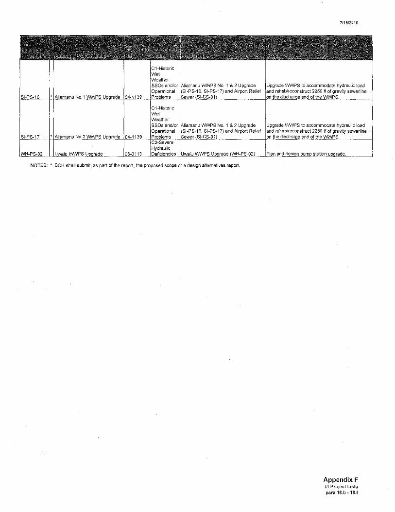
NOTES: * CCH shall submit. as part of the report, the proposed scope or a design alternatives report.
711512010
Upgrade WVVPS to accommodate hydraulic load rehab/reconstruct 2250 If of gravity sewerline
Upgrade WVVPS to accommodate hydraulic load and rehab/reconstruct 2250 If of gravity sewerline
Appendix F Itl Project Lists para 18.b - 18.f
APPENDIXG (List of Deferred Projects from Wet Weather III Assessment Update)

Honouliuli Relief Sewers
N-CS-11 Halawa Relief Sewers
HN-CS-12 Relief Sewer
HN-CS-15 Pearl 1 Relief
HN-CS-16 Mililani Relief Sewer
HN-C Relief Sewer
Heights Relief
Enchanted Lake Relief
NE
KK-CS-OB NONE
Maunawili Relief KK-CS-19 NONE
7/15/2010
III Plan concept to construct relief for Trunk.
III Plan concept to construct relief ."",r"r. in Halawa.
III Plan concept to construct relief sewers in Aiea Recreation Park.
III Plan concept to construct relief near Pearl Stream.
III Plan concept to construct relief I."'''''F''·. along Makaimoimo Street.
I Plan concept to construct relief Waimakua Drive.
III Plan concept to construct relief sewers along lliee Street and
Scott Elem School.
III Plan concept to construct relief Akumu Street.
III Plan concept to construct relief Isewer's along Auloa Road, Maunawili Loop and Aloha Oe Drive.
Appendix G Deferred Projects List
para 1B.g

KK-CS-26 Keaahala Relief Sewer
I W"ik,lpoki Relief KK-CS-27 NONE
Maunawili Estates KK-PS-14 WWPS NONE
WWPTF KK-TP-04 NONE
WWPTF NONE
Republican St. Relief SI-CS-03 Sewer NONE
SI-CS-04 Auiki St. Relief Sewer NONE
Nimitz Highway-Awa Relief Sewer NONE
Cooke St. Relief 2 Sewer NONE
Ave Relief 3 Sewer NONE
Nenue Street Relief SI-CS-21 Sewer NONE
Hydraulic Deficiencies
Moderate Hydraulic Deficiencies
3-
Hydraulic Deficiencies
I I
Third 5-Block
C3-
Hydraulic Deficiencies
3-Moderate Hydraulic Deficiencies
Moderate Hydraulic Deficiencies
I i Third 5-
Block
C3-
Hydraulic i I
III Plan concept to construct relief sewers between William Henry Rd and Rd.
III Plan concept to construct relief sewers I Mahalani Circle.
Plan concept to expand capacity of Maunawili Estates
IWVW'S from 0.79 mgd to 1.17
Plan concept to expand the IC8pa'8liry of Ahuimanu WWPTF to
Plan concept to construct wet basin of 1.70
Plan concept to construct relief Street.
III Plan concept to construct relief Auiki Street.
III Plan concept to construct relief Cooke Street.
III Plan concept to construct relief Ward Ave.
III Plan concept to construct relief sewers Nenue Street.
Deferred Projects List para 18.g

Lowrey Avenue Relief Sewer NONE
C3-Moderate Hydraulic Deficiencies
C3-Moderate Hydraulic 9th Avenue Relief
Sewer NONE Deficiencies
3-
Hydraulic Nuuanu Relief Sewer NONE Deficiencies
Moderate Hydraulic
-CS-32 Kaimuki Relief Sewer NONE Deficiencies
St. Relief Sewer PVT
Saratoga Road Relief Sewer
i Relief Sewer
Niu Valley WWPS 3 NONE
C3-Moderate Hydraulic Deficiencies
C3-Moderate Hydraulic Deficiencies
Moderate Hydraulic Deficiencies
C3-Moderate Hydraulic Deficiencies
C3-Moderate Hydraulic Deficiencies
Moderate Hydraulic Deficiencies
III Plan concept to construct relief sewers 19th Ave.
III Plan concept to construct relief sewers within Nuuanu area.
III Plan concept to construct relief sewers Olokele Ave.
III Plan concept to construct relief sewers Ahui Street
Plan concept to construct relief oPIA,pr. within the Fort DeRussy
Plan concept to construct relief I Road.
III Plan concept to construct relief from lolani School to Stream.
Plan concept to construct relief within the Waikiki area.
Appendix G Deferred Projects List
para 18.g

Whitmore Village WH-CS-02 Relief
Grandview WWPS
Waianae WNTP Influent Pump Station
rade
Final Sewer III Plan, Block 4
Lanikai Relief Sewer
KK-CS-16 I ana St Relief Sewer
Akumu St Relief 17 Sewer
Pohakupu Relief Sewer
Aala WWPS U
Maunawili WWPS KK-PS-08 rade
Salt Lake Relief
NONE
Hydraulic NONE Deficiencies
C4-Minor Hydraulic
E Deficiencies
Hydraulic NONE Deficiencies
C4-Minor Hydraulic
NONE Deficiencies
C4-Minor Hydraulic
NON Deficiencies
C4-Minor Hydraulic
NONE Deficiencies
C4-Minor Hydraulic
NONE Deficiencies
C4-Minor Hydraulic Deficiencies
III Plan concept to construct relief 0""".,,,",0 along Ihiihi Ave and
Street.
III Plan concept to increase the of the IPS to 15.8
III Plan concept to construct relief sewers I Mokula Drive.
III Plan concept to construct relief sewers I Auwinula Rd.
III Plan concept to construct relief sewers I Keolu Drive.
III Plan concept to construct relief sewers along Kailua Road, Ulupii St and i Street.
III Plan concept to expand the capacity of Aala WWPS from 0.72 to 0.94
III Plan concept to construct relief within the Salt Lake area.
Appendix G Deferred Projects List
para 18.g

C4-Minor Hydraulic
SI-CS-14 Makiki Relief Sewer NONE Deficiencies
C4-Minor Lewers Street Relief Hydraulic
SI-CS-16 Sewer NONE Deficiencies
C4-Minor Niu Valley Shopping Hydraulic
19 Relief Sewer NONE Deficiencies
C4-Minor Pueo Street Relief Hydraulic III Plan concept to construct relief
-CS-20 Sewer NONE Deficiencies sewers I Pueo SI.
SI. Relief III Plan concept to construct relief -CS-23 I Alakea Street.
inor Huapala Street Relief Hydraulic III Plan concept to construct relief
SI-CS-25 Deficiencies sewers I St.
I Street Relief lie III Plan concept to construct relief sewers I Mahiole St.
III Plan concept to construct relief Heights Relief sewers within the Alewa Heights
SI-CS-44 area.
Road Relief III Plan concept to construct relief sewers I Kalia Rd.
Park VVWPS SI-PS-07
i reevaluated. Portion along
Fort DeRussy VVWPS Kalakaua Ave from Ala Wai Main Canal to the East End Relief
Sewer was I in 2009.
C4-Minor i i Hydraulic III Plan concept to construct relief
NONE sewers I Rd.
Appendix G Deferred Projects List
para 18.g

APPENDIXH (Gravity Main Rehabilitation/Replacement Projects: Years One through Three)
City and County of Honolulu
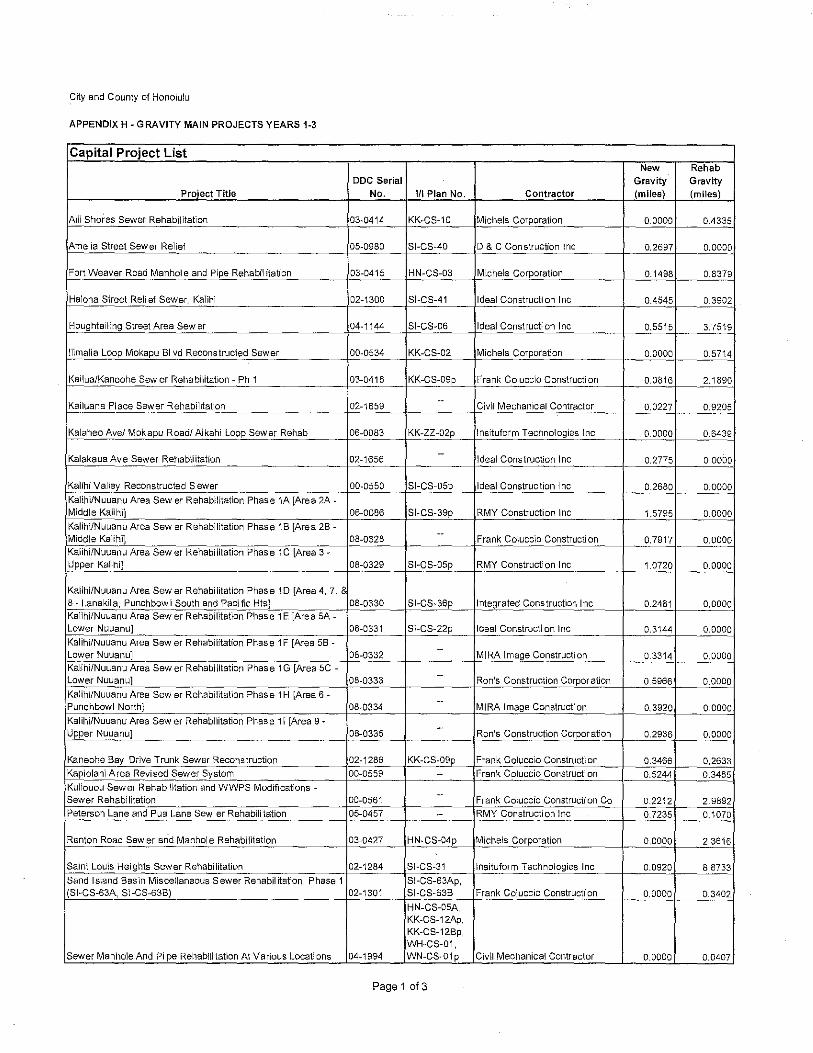
APPENDIX H - GRAVITY MAIN PROJECTS YEARS 1-3
Capital Project List New Rehab
DDC Serial Gravity Gravity Project Title No. III Plan No. Contractor (miles) (miles)
Alii Shores Sewer Rehabilitation 03-0414 KK~CS-10 Michels Corporation 0,0000 0.4335
Amelia Street Sewer Relief 05-0980 SI-CS-4D 0& C Construction Inc 0,2697 0.0000
Fort Weaver Road Manhol e and Pipe Rehabil itation 03-0415 HN-CS-03 Michels Corporation 0.1498 0.8379
Halona Street Reli ef Sewer, Kalihi 02-1300 SI-CS-41 Ideal Construction Inc 0.4545 0.3902
Houghtailing Street Area Sewer 04-1144 SI-GS-D6 Ideal Construction Inc 0.5515 3.7519
llimalia Loop Mokapu 81 vd Recons trucled Sewer 00-0534 KK-CS-D2 Michels Corporation 0.0000 0.5714
Kailua/Kaneohe Sewer Rehabilitation - Ph 1 03-0418 KK-CS-D9p Frank Coluccio Construction 0.0816 2.1890
--Kailuana Place Sewer Rehabilitation 02-1659 Civil Mechanical Contractor 0,0227 0.9205
Kalaheo Ave! Mokapu Roadl Aikahi Loop Sewer Rehab 06-0083 KK-ZZ-D2p Insituform Technologies Inc 0,0000 0,6439
--Kalakaua Ave Sewer Rehabilitation 02-1656 Ideal Construction Inc 0.2775 0,0000
Kalihi Valley Reconstructed Sewer 00-0550 SI-CS-D5p Ideal Construction Inc 0.2680 0.0000 Kalihi/Nuuanu Area Sewer Rehabilitation Phase 1A IArea 2A ~ Middle Kalihi] 06-0086 SI-CS-39p RMY Construction Inc 1.5795 0.0000 Kalihi/Nuuanu Area Sewer Rehabilitation Phase 18 [Area 28- --Middle Kalihi] 08-0328 Frank Coluccio Construction 0,7917 0.0000 Kalihi/Nuuanu Area Sewer Rehabilitation Phase 1C [Area 3-Upper Kalihi] 08-0329 SI-CS-D5p RMY Constructi on Inc 1.0720 0.0000
Kalihi/Nuuanu Area Sewer Rehabilitation Phase 10 [Area 4,7, 8 8 - Lanakila, Punchbowl South and Pacific Hts] 08-0330 SI-CS-36p Integrated Construction Inc 0.2481 0.0000 Kalihi!Nuuanu Area Sewer Rehabilitation Phase 1E [Area 5A-Lower Nuuanu] 08-0331 SI-CS-22p Ideal Construction Inc 0.3144 0.0000 Kalihi/Nuuanu Area Sewer Rehabilitation Phase 1 F [Area 58 -
--Lower NuuanuJ 08-0332 MIRA Image Construction 0.3314 0.0000 KalihifNuuanu Area Sewer Rehabilitation Phase 1G [Area 5C -Lower Nuuanu] 08-0333
--Ron's Construction Corpor ation 0,5966 0.0000
KalihifNuuanu Area Sewer Rehabilitation Phase 1H [Area 6---
Punchbowl North] 08-0334 MIRA Image Construction 0,3920 0.0000 Kalihi/Nuuanu Area Sewer Rehabilitation Phase 11 [Area 9· --Upper Nuuanu] 08-0335 Ron's Construction Corporation 0.2936 0.0000
Kaneohe 8ay Drive Trunk Sewer Reconstruction 02-1286 KK-CS-09p Frank Coluccio Construct; on 0.3466 0,2633 Kapiolani Area Revised Sewer System 00-0559 -- Frank Coluccio Constructi on 0.5244 0.3485 Kuliouou Sewer Rehabilitation and WWPS Modifications - --Sewer Rehabilitation 00-0561 F rank Coluccio Constructi on Co 0.2212 2.9892 Peterson Lane and Pua Lane Sewer Rehabilitation 05-0457 -- RMY Constructi on Inc 0.7235 0.1070
Renton Road Sewer and Manhol e Rehabi litation 03-0427 HN-CS-04p Michels Corporation 0.0000 2.3616
Saint Louis Heights Sewer Rehabilitation 02-1284 SI-CS-31 lnsituform Technologies Inc 0.0920 8,8733
Sand Island Basin Miscellaneous Sewer Rehabil itation, Phase 1 SI-CS-63Ap, (SI-CS-63A, SI-CS-638) 02-1301 SI-CS-638 Frank Coluccio Construct! on 0,0000 0.3402
HN-CS-05A, KK-CS-1 2Ap, KK-CS-128p, WH~CS-01,
Sewer Manhole And Pi pe Rehabilitation At Various Locations 04-1994 WN-CS~01p Civil Mechanical Contractor 0.0000 0.0407
Page 1013
City and County of Honolulu
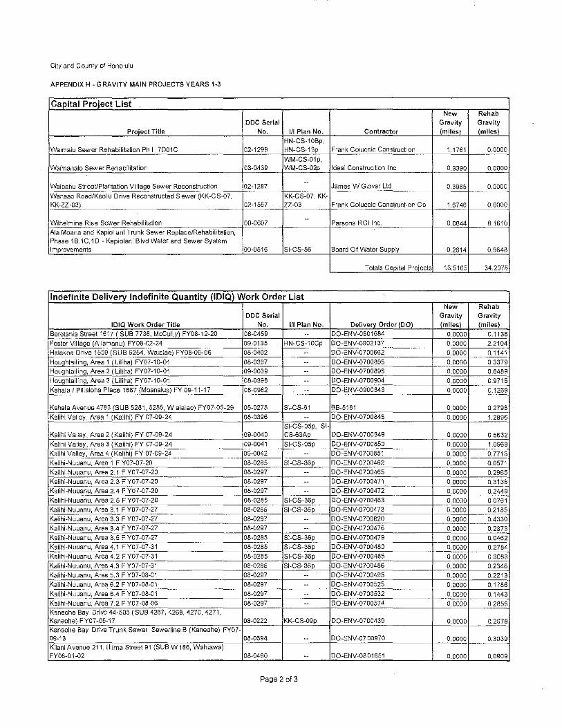
APPENDIX H - GRAVITY MAIN PROJECTS YEARS 1-3
Capital Project List New Rehab
DOC Serial Gravity Gravity
Project Title No. III Plan No. Contractor (miles) (miles)
HN-CS-10Bp,
Waimalu Sewer Rehabilitation Ph I, 7D01G 02-1299 HN-CS-13p Frank Coluccio Construction 1,1761 0.0000
WM-GS-01p, Waimanalo Sewer Rehabilitation 03-0439 WM-GS-02p Ideal Construction Inc 0.3390 0.0000
--Waipahu Street/Plantation Village Sewer Reconstruction 02-1287 James W Glover Ltd 0.3985 0,0000
Wanaao Road/Keol u Drive Reconstructed Sewer (KK-CS-07, KK-CS-07, KK-KK-ZZ-03) 02-1557 ZZ-03 Frank Coluccio Construction Co 1,6746 0.0000
--Wilhelm ina Rise Sewer Rehabil itation 00-0607 Parsons RCllnc. 0.0644 8.1610
Ala Moana and Kapiol ani Trunk Sewer Replace/Rehabilitation, Phase 1B, 1C,1 D - Kapiolani Blvd Water and Sewer System Improvements 00-0516 SI-CS-56 Board Of Water Supply 0.2614 0.9848
Totals Capital Projects 13,5165 34.2078
Indefinite Delivery Indefinite Quantity (IOIQ) Work Order List New Rehab
DOC Serial Gravity Gravity
IOIQ Work Order Title No. III Plan No. Delivery Order (DO) (miles) (miles)
Beretania Street 1617 (SUB 7736, McCully) FY08-12-20 08-0459 -- DO-ENV-0801684 0.0000 0.1138
Foster Village (Aliamanu) FY08-02-24 09-0135 HN-GS-10Gp DO-ENV-0902137 0,0000 2.2104
Halekoa Drive 1509 (SUB 5254, Waialae) FY08-09-06 08-0402 -- DO-ENV-0700662 0.0000 0.1141
Houghtailing, Area 1 (LiHha) FY07-10-01 08-0397 -- DO~ENV-0700895 0.0000 0.3379
Houghtailing, Area 2 (Liliha) FY07-10-01 09-0039 -- DO-ENV-0700896 0,0000 0.6489
Houghtailing, Area 3 (Liliha) FY07-10-01 08-0398 -- DO-ENV-0700904 0.0000 0.9715
Kahala I Pilialoha Place 1687 (Moanalua) FY 09-11-17 08-0982 -- DO-ENV-0900843 0.0000 0.1269
Kahala Avenue 4783 (SUB 5281, 5285, W aialae) FY07-05-29 05-0278 SI-GS-61 BB-5181 0.0000 0.2798
Kalihi Valley, Area 1 (Kalihi) FY 07-09-24 08-0396 -- DO-ENV-0700848 0.0000 1.2896
SI-GS-OSp, SI Kalihi Valley, Area 2 (Kalihi) FY 07-09-24 09-0040 CS-63Ap DO-ENV-0700849 0.0000 0,5632
Kalihi Valley, Area 3 (Kalihi) FY 07-09-24 09-0041 SI-CS-05p DO-ENV-0700850 0.0000 1.0969
Kalihi Valley, Area 4 (Kalihi) FY 07-09-24 09-0042 -- DO-ENV-0700851 0.0000 0.7713
Kalihi-Nuuanu, Area 1 F Y07-07-20 08-0285 SI-GS-36p DO-ENV-0700462 0,0000 0.0571
Kalihi-Nuuanu, Area 2.1 F Y07-07-20 08-0297 -- DO-ENV-0700465 0.0000 0.2965
Kalihi-Nuuanu, Area 2.3 F Y07-07-20 08-0297 -- DO-ENV-0700471 0.0000 0.3138 -- "-" ..
Kalihi-Nuuanu, Area 2.4 F Y07-07-20 08-0297 -- DO-ENV-0700472 0.0000 0.2449
Kalihi-Nuuanu, Area 2.5 F Y07-07-20 08-0285 SI-CS-36p DO-ENV"0700463 0.0000 0,0761
Kalihi-Nuuanu, Area 3.1 F Y07-07-27 08-0285 SI-GS-36p DO-ENV-0700473 0.0000 0.2185
Kalihi-Nuuanu, Area 3,3 F Y07-07-27 08-0297 -- DO-ENV-0700620 0,0000 004330
Kalihi-Nuuanu, Area 3.4 F Y07-07-27 08-0297 -- DO-ENV-0700476 0,0000 0.2373
Kalihi-Nuuanu, Area 3,5 F Y07-07-27 08-0285 SI-CS-36p DO-ENV~0700479 0.0000 0.0462
Kalihi-Nuuanu, Area 4,1 F Y07-07-31 08-0285 SI-CS-36p DO-ENV-0700480 0.0000 0.2784
Kalihi-Nuuanu, Area 4.2 F Y07-07-31 08-0285 SI-GS-36p DO-ENV-0700485 0.0000 0,3083
Kalihi-Nuuanu, Area 4.3 F Y07-07-31 08-0285 SI-CS-36p DO-ENV-0700486 0.0000 0.2348
Kalihi-Nuuanu, Area 5.3 F Y07-08-01 08-0297 -- DO-ENV-0700495 0,0000 0.2213
Kalihi-Nuuanu, Area 6,2 F Y07-08-01 08-0297 -- DO-ENV-070052S 0.0000 0.1786
Kalihi-Nuuanu, Area 6.4 F Y07-0B-01 08-0297 -- DO-ENV-0700532 0.0000 0.1443
Kalihi-Nuuanu, Area 7,2 F Y07-08~06 08-0297 -- DO-ENV-0700574 0.0000 0,2856 Kaneohe Bay Drive 44-505 (SUB 4267, 4268, 4270, 4271, Kaneohe) FY07-05-17 08-0222 KK-CS-09p DO-ENV-0700439 0.0000 0.2978 ._----Kaneohe Bay Drive Trunk Sewer, Sewerline B (Kaneohe) FY07-09-13 08-0394 -- DO-ENV-07 00970 0.0000 0,3039
Kilani A venue 211, lilima Street 91 (SUB W 186, Wahiawa) FY08-01-02 08-0460 -- DO-ENV-0801651 0.0000 0.0909
Page 2 of 3

City and County of Honolulu
APPENDIX H - GRAVITY MAIN PROJECTS YEARS 1-3
Indefinite Delivery Indefinite Quantity (IOIQ) Work Order List New Rehab
DOC Serial Gravity Gravity IDIQ Work Order Title No. III Plan No. Delivery Order (DO) (miles) (miles)
Komo Mai Drive 1860 (SUB 2094, 2095, Pear.! City) FY08~06~13 08~0462 -- DO-ENV-0802714 0.0000 0.2~Q~ -
_~eighton Street 815 (SUB 5114, 5116, Kuli ouou) FY08-06-18 08-0210 -- DQ~ENV-0802727 0.0000 0.2561 .-Makalii Place 350, Kailua Road (SUB 4612, 4661, Kai lua) FY07-05-17 08-0223 KK-CS-06p BB~5183 0.0000 0.2129 ----Mikiola Drive I Alakai Street I Likeke Place (Kaneohe) F Y-07-09-28 08~0395 KK-CS-09p OQ-ENV-0700906 0.0000 0.4053
Mulehu Street 94-436 (SUB 0446, Mililani) FY09-09-30 08-0981 HN-CS-05Bp DQ~ENV-0900556 0.0000 ()~
Nanamoana Street 44~ 121 (SUB 3994, Kaneohe) F Y07~06-06 08-0260 -- BB-5188 0.0000 0.0212
Waialae Iki, Area 4 (Kuliouou) FY07~11-15 08~0408 -- DO-ENV-0701322 0.0000 0.5375 -,vyaialae 1~~~,~~_I:!~~~!i_~uou) Fy~!_~-.~_ DQ-ENV-0701323 09~0043 --
--0,0000 - 0.2962
.. _-- --- --- --- - --,,----------------- --,,---- .. ----
Waialae Iki, Area 6 (Kulio~ou) FY07-11·15 09-0044 -- DO-ENV-0701324 0.0000 0.2786 _ ...
HN-CS-10Bp. Waimalu Sewer Rehabilitation (Aiea) FY09-06-29 ~-- HN-CS-13p OO-ENV-1000243
.-~-
0,0000 0.4561 Waimanalo Sewers (SUB HAWN, PRIV: 2017,2013,
- ~c"'s~ -... - .. _----_ ...
~aimanalo) FY07-10-05 08-0403 II\IM-CS-02p OQ-ENV-0700963 0.0000 "EQ5 - ._- ~- . Waipahu Depot Street, Farrington Highway (SUB 0887, Waipahu) FY09-09-30 08-0980 HN-CS-05Bp DQ-ENV-0900557 0,0000 0,0145
Totals 1010 0,0000 15.9509
Totals Capital Projects 13.5165 34.2078
Total Gravity Mains (miles)
Note; p; portion of the project
Page 3 of 3
APPENDIX I (List of Currently Authorized Positions for CCH's Staffing Commitment)

APPENDIX I
CSM Required Staffing
Below are the currently funded positions to implement the duties of CCH's CSM program to operate and maintain the gravity sewer portion of CCH' s Wastewater Collection System:
Non-Field Positions 20 Field Positions 134 Total 154
APPENDIXJ (Equipment Inventory)

APPENDIX J
CSM Required Equipment Inventory
EQUIPMENT INVENTORY WITH 1 SPARE VACTORS 10 CESSPOOL TRUCKS 5 RODDERS 8 CCTVVANS 4 TANKERS * 4 . Tankers are wlthm the DIvision of Wastewater Treatment & Disposal
I
APPENDIXK (Provisions of HAR Chapter 11-62 (as amended on April 15, 1997))

Appendix KHawaii Administrative Regulations Chapter 11-62, Appendix C
(As amended on April 15, 1997)
C.2.a. Applicability. Any wastewater spill which enters into state waters from . . . [CCH’s]wastewater system.
C.4.a. Applicability. Any wastewater spill from . . . [CCH’s] wastewater system onto theground and that does not enter state waters but is in an area which is or may be accessible to thepublic. (1) In this appendix, the public includes hotel, apartment, and condominium residents andguests, or condominium apartment owners at their own condominium, and managementpersonnel and building or facility staff, unless the person is specifically an operator of thewastewater system or a manager of the property. (2) In this appendix, areas inaccessible to the public include areas: (a) Confined within a fenced or walled (six foot high with locked gate or door) area; and (b) Contact with the spill is limited to wastewater system operating personnel and managementpersonnel for the property owner or lessee. (3) Exclusion. Spills of R-1 water provided the owner/agent demonstrates that the spill was ofR-1 water and that BMPs as approved by the director were implemented.
C.5.a. Applicability. All wastewater spills from . . . [CCH’s] wastewater system that does notenter state waters and are in areas inaccessible to the public. (1) The public and inaccessibility are described in section 4.a. (2) Exclusion. Spills of R-1 water provided the owner/agent demonstrates that the spill was ofR-1 water and that BMPs as approved by the director were implemented.
C.5.c. Reporting. For spills of a thousand gallons or more, and for spills occurring more thantwice within a 12 month period within the confines or fence line of . . . [CCH’s] wastewatersystem, the owner/agent shall report to the WWB under section 9.a.
C.5.d. Recording. The owner/agent shall record and tabulate the date and time of the spill, theamount released, the cause(s) for the spill, clean up efforts, and remedial actions taken to preventfuture spills for all spills greater than 50 gallons as they happen. The owner/agent shall keep therecords and tabulations on site and make the records and tabulation available to the director forinspection and copying.