Appendix A Permit Application Summary -...
68
Appendix A Permit Application Summary
Transcript of Appendix A Permit Application Summary -...

Appendix A Permit Application Summary

Appalachian Shale Cracker Enterprise, LLC (ASCENT) 5100 Westheimer Road Suite 585 Houston, TX 71056 Permit Application Summary Washington, West Virginia
May 2014 Prepared by: Environmental Resources Management 204 Chase Drive Hurricane, WV, 25526


PROJECT ASCENT I MAY 2014
TABLE OF CONTENTS
1.0 INTRODUCTION 1
1.1 PURPOSE 1
1.2 PROJECT OVERVIEW 1
1.3 PROJECT SCHEDULE 2
1.4 APPLICATION ORGANIZATION 2
2.0 PROJECT DESCRIPTION 3
2.1 ETHANE CRACKER PLANT 4
2.2 POLYETHYLENE (PE) PLANTS 11
2.3 SUPPORT UTILITIES 16
3.0 PROJECT EMISSIONS 20
3.1 OVERVIEW AND METHODOLOGY 20
3.2 FACILITY WIDE EMISSIONS 20
3.3 ETHANE CRACKER PLANT EMISSIONS 26
3.4 POLYETHYLENE PLANTS EMISSIONS 32
3.5 SUPPORT UTILITIES EMISSIONS 36
4.0 PREVENTION OF SIGNIFICANT DETERIORATION (PSD) 43
4.1 APPLICABILITY 43
4.2 BEST AVAILABLE CONTROL TECHNOLOGY ANALYSIS 44
4.3 NAAQS DISPERSION MODELING ANALYSIS 47
5.0 NON-ATTAINMENT NEW SOURCE REVIEW (NA-NSR) 48
6.0 APPLICABLE REQUIREMENTS REVIEW 49
6.1 FEDERAL REQUIREMENTS 49

PROJECT ASCENT II MAY 2014
6.2 WEST VIRGINIA STATE REQUIREMENTS 58
7.0 CONCLUSIONS 62
LIST OF TABLES
Table 3-1 Facility Wide Potential Emissions
Table 3-2 Hazardous Air Pollutant Potential Emissions
Table 3-3 Greenhouse Gases Potential Emissions
Table 3 -4 Ethane Cracker Emission Sources
Table 3-5 Cracker Fuel Gas Mixture Heating Value
Table 3-6 Pyrolysis Furnaces Potential Emissions per Furnace
Table 3-7 Thermal Oxidizer Potential Emissions
Table 3-8 Ethane Cracker Plant Fugitives Potential Emissions
Table 3 -9 Polyethylene Plants Emission Sources
Table 3-10 Regenerative Thermal Oxidizer Potential Emissions
Table 3-11 Polyethylene Plants Fugitives Potential Emissions
Table 3 -12 Support Utility Emission Sources
Table 3-13 Storage Tanks Potential Emissions
Table 4-1 PSD Applicability Summary
Table 4-2 BACT Analysis Summary
LIST OF FIGURES
Figure 2-1 Ethane Cracker Process Flow Diagram
Figure 2-2 Pyrolysis Furnace Decoking Operations
Figure 2-3A PE Plant A Process Flow Diagram
Figure 2-3B PE Plant B Process Flow Diagram
Figure 2-3C PE Plant C Process Flow Diagram

PROJECT ASCENT 1 MAY 2014
1.0 INTRODUCTION
1.1 PURPOSE
The Appalachian Shale Cracker Enterprise, LLC (ASCENT) Project (the “Project”) proposes the construction of a new industrial facility in Washington, Wood County, West Virginia, approximately 10 kilometers southwest of Parkersburg, West Virginia.
Because the air quality in the area already attains all applicable national ambient air quality standards, the Project is subject to Prevention of Significant Deterioration (PSD) program. The potential air quality emissions from the proposed Project make the facility a major source for purposes of the PSD program in the State of West Virginia; therefore, all PSD permit application proceedings are required. This application includes all necessary information to support the PSD permit application in accordance with West Virginia Code of State Rules Title 45, Series 14 (45 CSR 14) including: a description of the proposed emission sources; the estimated air emissions for the project; an assessment of the control technologies implemented for the project; an assessment of the emissions to air quality per air dispersion modeling; and supporting documentation.
The completed PSD permit application forms required to be submitted to the West Virginia Department of Environmental Quality (WVDEP) are included as part of this application.
1.2 PROJECT OVERVIEW
The ASCENT Project proposes the construction of a new industrial facility on the east bank of the Ohio River at the site of an existing plastics facility in Washington, Wood County, West Virginia. The proposed site is approximately 376 acres of land. Braskem America (Braskem) closed on the final purchase of the southern portion of the property in January 2014. It later assigned the majority of the land to ASCENT and intends to assign the remainder shortly. Odebrecht is the ultimate parent company of ASCENT as well as of ASCENT’s affiliate, Braskem, which plans to operate the facility upon completion of construction.
The Project includes the construction of one Ethane Cracker Plant to process and reform raw ethane into ethylene and propylene, three Polyethylene Plants to produce various types of polyethylene, and

PROJECT ASCENT 2 MAY 2014
associated utility support. Site figures are located in Appendix B of the permit application including a Site Location Map (Figure B-1) and a Site Layout Map (Figure B-2). The proposed facility will manufacture inert polyethylene pellets, using ethane from Appalachian Shale as the raw material. The ethane is delivered to the plant via pipeline. The ethane will not be pure, but instead contains fractions of heavier hydrocarbons, which are cracked out and reformed. The ethane is thermally ‘cracked’ to produce ethylene and propylene that are, in turn, the feedstock to produce polyethylene. The polyethylene pellets are shipped from the site via rail or truck. Polyethylene is widely used in an array of plastic manufacturing industries, including everyday household and industrial items such as food containers, toys, shipping containers, piping, and adhesives.
1.3 PROJECT SCHEDULE
Construction of the Project is scheduled to commence the second quarter of calendar year 2015 based on a 12-month PSD permitting timeline from the time of this application. With an estimated 36 to 42 month construction schedule, commercial operation is expected to occur during the fourth quarter of 2018 or the first quarter of 2019.
1.4 APPLICATION ORGANIZATION
This application is organized into the following sections:
Section 2.0 provides a description of the Project emissions sources;
Section 3.0 discusses the potential emissions from the Project;
Section 4.0 discusses the PSD applicability;
Section 5.0 discusses the Non-Attainment New Source Review (NA-NSR) applicability;
Section 6.0 provides a summary of applicable federal and State air quality regulations; and
Section 7.0 provides a brief summary of the air quality assessment to support the air permit application.

PROJECT ASCENT 3 MAY 2014
2.0 PROJECT DESCRIPTION
The proposed ASCENT facility will be located at the previous SABIC plastic manufacturing site in Washington, Wood County West Virginia; adjacent to the Ohio River southeast of Parkersburg. The site is zoned for industrial use, and provides multiple strategic advantages for the processing of raw ethane captured from Appalachian Shale. The Project intends to construct and operate one Ethane Cracker Plant, three polyethylene plants, associated support utilities, process and storage tanks, and other miscellaneous sources. The design information discussed in this application is based on best available design information provided by vendors at the time of this application. The following section identifies the primary equipment and operations that will contribute to the facility-wide air emissions. The Ethane Cracker Plant will consist of the following;
Six (6) Pyrolysis Cracking Furnaces each with a rating of 396.8 million British Thermal Units per hour (MMBtu/hr) fired on a fuel mixture of recycled tail gas and natural gas;
One (1) natural gas-fired thermal oxidizer with a maximum heat input of 130 MMBtu/hr, used to control various product, recycle, and waste streams generated by the Ethane Cracker Plant;
One (1) emergency “main flare” equipped with duplicative natural gas piloted burners each rated at 0.41 MMBtu/hr (0.82 MMBtu/hr total). Note: The main flare also supports the three polyethylene plants; and
Three (3) flares equipped with natural gas piloted burners with a combined rating of 1.0 MMBtu/hr.
The primary emission sources associated with the three polyethylene plants will consist of the following;
One (1) natural gas-fired Regenerative Thermal Oxidizer (RTO) with a maximum heat input of 20 MMBtu/hr;
One (1) low pressure flare equipped with duplicative natural gas piloted burners each rated at 0.2 MMBtu/hr (0.4 MMBtu/hr total); and

PROJECT ASCENT 4 MAY 2014
One (1) natural gas-fired heater with a maximum heat input of 10 MMBtu/hr, associated with catalyst activation operations; and
Material handling operations. The emission sources associated with support utility operations will consist of the following;
One (1) natural gas fired GE 7EA Combustion Turbine with a maximum heat input of 942.6 MMBtu/hr, equipped with a natural gas-fired duct burner with a maximum heat input rating of 346MMBtu/hr;
Two (2) natural gas-fired auxiliary boilers each with a maximum heat input of 206 MMBtu/hr;
Nine (9) Ultra Low Sulfur Diesel (ULSD) fired emergency generators with heat inputs ranging from 350 kilowatts (kW) to 2800 kW;
Three (3) ULSD-fired fire water Pump engines each with a rating of 485 kW;
One (1) cooling tower for non-contact cooling utilized in both the production of ethylene and polyethylene;
One (1) Wastewater Treatment Plant (WWTP) comprised of a wastewater collection system, an effluent treatment system, and a waste reuse and final discharge system; and
Storage tanks and loading racks.
Process flow diagrams for the emissions sources associated with the Project are included in Appendix C of the permit application.
2.1 ETHANE CRACKER PLANT
The ethane feedstock for the Ethane Cracker Plant will consist of Appalachian Shale ethane, supplied via pipeline, and recycled hydrocarbon feeds. The ethane feedstock coming from the pipeline is handled and condensed inside a storage unit. The ethane storage consists of three storage ‘bullet’ tanks to store the ethane feed for the Cracker Plant
PROJECT ASCENT 5 MAY 2014
in case of unavailability of straight-run feedstock from the upstream gas pipeline. The ‘cracking’ process refers to the thermal breakdown of large complex organic molecules, such as ethane, into smaller organic constituents, such as ethylene and propylene. A process flow diagram for the Ethane Cracker Plant is presented in Figure 2-1, which outlines all major processes and equipment, including cracking furnaces, a quench tower, a compressor section, a caustic removal section, an ethylene recovery section, and the thermal oxidizer.
2.1.1 Pyrolysis Furnaces
The Project is for the construction of six pyrolysis (i.e., cracking) furnaces, each with a maximum heat input rating of 396.8 MMBtu/hr, in order to thermally ‘crack’ the ethane feedstock into ethylene and other products. In normal steady state operations, five cracking furnaces are fired to process the ethane feedstock (1,984 MMBtu/hr at 100% load) while one cracking furnace will be maintained on hot stand-by. All six furnaces will be identically designed to crack the mixture of ethane and recycled hydrocarbon streams.
Each furnace will consist of a single cell radiant section (i.e., firebox) with bottom and side fired burners, a convection section, and an induced draft fan. The fuel source used by the furnaces will consist of a blend of natural gas and recycled tail gas. The fuel blend will be a hydrogen rich gas mixture with an estimated heating value of 523 Btu per standard cubic foot (scf). The fuel combustion will take place in two firing zones for each furnace, one on either end of the firebox. An induced draft fan, located on top of the convection section, will be driven by a variable speed electric motor to produce draft in the furnace. All bottom and side burners associated with the six furnaces will utilize Ultra-low NOx Burners (ULNB) with vendor guaranteed control efficiencies on total NOx emissions. Section 3.0 of this application provides a more detailed discussion on emissions and control equipment for each furnace. Each furnace will have its own exhaust stack and each stack is expected to be at least 65 meters above grade. The furnaces are designed with the intention to operate on a continual basis.
2.1.2 Coke Formation and Removal
The actual “cracking” of ethane and hydrocarbon feeds involves the dehydrogenation and condensation of ethane, such that only olefins are produced in the radiant coils. Because of this thermal reaction, the radiant
PROJECT ASCENT 6 MAY 2014
tubes gradually become coated with an internal layer of coke, causing an increase in metal temperature and an increase in pressure drop through the radiant coils. This coke layer tends to retard the heat transfer from the tube walls of the radiant coil to the feed passing through it, which adversely affects the pyrolysis yield pattern.
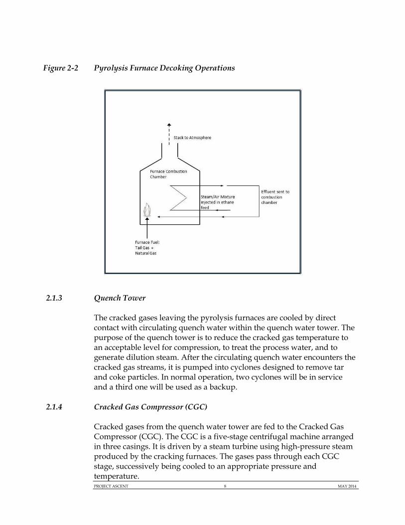
The coke accumulation on the radiant coils necessitates periodic cleaning, referred to as “decoking”, with one cleaning event typically occuring every 60 to 70 days per furnace, in order to prevent overheating and to restore the original yield pattern. The cleaning of the coke deposits is achieved by lowering the firing rate to thirty percent normal firing rate (approximately 119 MMBtu/hr) and injecting a steam/air mixture into the tubes to burn off the coke, a procedure known as decoking. During the decoking procedure, the furnace effluent from the radiant tubes is routed back to the firebox for additional pollutant destruction. To control the burning of the coke, a sample point for CO2 analyses is installed on the decoking effluent to ensure full oxidation of the coke material occurs. Figure 2-2 depicts the decoking procedures used for each of the six pyrolysis furnaces.

PROJECT ASCENT 7 MAY 2014
Figure 2-1 Ethane Cracker Process Flow Diagram
PROJECT ASCENT 8 MAY 2014
Figure 2-2 Pyrolysis Furnace Decoking Operations
2.1.3 Quench Tower
The cracked gases leaving the pyrolysis furnaces are cooled by direct contact with circulating quench water within the quench water tower. The purpose of the quench tower is to reduce the cracked gas temperature to an acceptable level for compression, to treat the process water, and to generate dilution steam. After the circulating quench water encounters the cracked gas streams, it is pumped into cyclones designed to remove tar and coke particles. In normal operation, two cyclones will be in service and a third one will be used as a backup.
2.1.4 Cracked Gas Compressor (CGC)
Cracked gases from the quench water tower are fed to the Cracked Gas Compressor (CGC). The CGC is a five-stage centrifugal machine arranged in three casings. It is driven by a steam turbine using high-pressure steam produced by the cracking furnaces. The gases pass through each CGC stage, successively being cooled to an appropriate pressure and temperature.
PROJECT ASCENT 9 MAY 2014
2.1.5 Caustic Removal and Gas Drying
Between the fourth and fifth stages of the CGC, the cracked gas product feed will be routed to an acid gas removal section (caustic soda scrubber) to eliminate excess carbon dioxide and hydrogen sulfide. All spent caustic solution will be withdrawn from the column and be sent to the spent caustic treatment, where it will undergo a partial degasification of the volatile hydrocarbons.
The chilled gas leaving the fifth stage of the CGC is routed to one of two cracked gas driers (one in operation and one in stand-by mode). The gas flows from the top to the bottom of the drier, while the water content of the gas is successively reduced to less than 1 ppm or less. The driers use regeneration gas, sent in a counter current direction (bottom to top), to release the adsorbed water from the cracked gas.
2.1.6 Ethylene Recovery and Purification
The final recovery of ethylene is achieved by condensation in a chilling section and a series of purification steps. Processed gases leave the driers and pass through a gas filter before entering the chilling section. Ethylene and heavier hydrocarbons are condensed progressively by chilling the gases in steps at below freezing temperatures. Condensation is achieved by the use of a mixed refrigerant through an open loop type refrigeration system. After being chilled, the cracked gases are then routed for separation and purification.
Ethylene is separated from recycled hydrocarbons in a series of distillation steps. First, the cracked gasses are routed to a demethanizer where light components such as methane, are extracted from the overhead product and routed back to the CGC for recycle. The bottom product is reheated and transferred to the deethanizer. The overhead product of the deethanizer (C2 stream) is sent to the acetylene reactor and the bottom product is sent to the depropanizer and the debutanizer. Ethylene is sent to a double-walled refrigerated storage tank. Propylene, raw mix C4s (mostly butadiene), and pyrolysis gasoline are final products sent to storage tanks from the process. Propylene, raw mix C4s, and pyrolysis gasoline are transferred as final product off site via loading racks. Ethylene is sent as the primary input to the polyethylene plants.

PROJECT ASCENT 10 MAY 2014
2.1.7 Thermal Oxidizer
One thermal oxidizer will be constructed and operated for the control of organic vapor and liquid streams generated by the Ethane Cracker Plant. The thermal oxidizer is equipped with a radiant section and a natural gas burner rated at 130 MMBtu/hr. ASCENT is coordinating with the design technology vendors to properly identify all streams to the thermal oxidizer. The potential streams sent to the oxidizer include slop oil, tar water, wet flare condensates and hydrocarbons. Liquid streams generated by the Ethane Cracker Plant not sent to the thermal oxidizer will be sent to the WWTP for treatment and final disposal, described in more detail below. All product and recycle feeds associated with the Ethane Cracker Plant will also be connected to the main flare inlet feeds in the event of any unplanned over pressuring event. The WWTP is discussed in Section 2.3.5. The flares are discussed in Section 2.1.8 below.
The thermal oxidizer is designed to achieve a Destruction and Removal Efficiency (DRE) of 99.9% for all VOC and organic HAP constituents.
2.1.8 Ethane Cracker Flares
Four flare stacks will be designed and constructed for the Ethane Cracker operations; the main flare, oxygen flare, ethylene storage flare and product storage flare. Each flare will be equipped with a primary natural gas pilot and an identical backup natural gas pilot. All four flares will have a 98 % DRE for all streams sent for combustion.
The main flare will be constructed and operated for any unplanned over pressuring emergency event. The main flare is also connected to the three polyethylene plants described in Section 2.2. The main flare pilots will have a combined heat input of 0.82 MMBtu/hr.
The oxygen flare will be constructed to control pressure relief from the thermal oxidizer. The oxygen flare pilots will have a combined heat input of 0.2 MMBtu/hr. The ethylene storage flare will be constructed to control any flammable gases generated from the ethylene storage silos. The product storage flare will be constructed to control any flammable gases generated from the propylene and gasoline storage tanks. These two flare stacks will each be identically designed with natural gas pilots, each having a total heat input of 0.4 MMBtu/hr. This heat input incorporates natural gas backup pilots.
PROJECT ASCENT 11 MAY 2014
2.2 POLYETHYLENE (PE) PLANTS
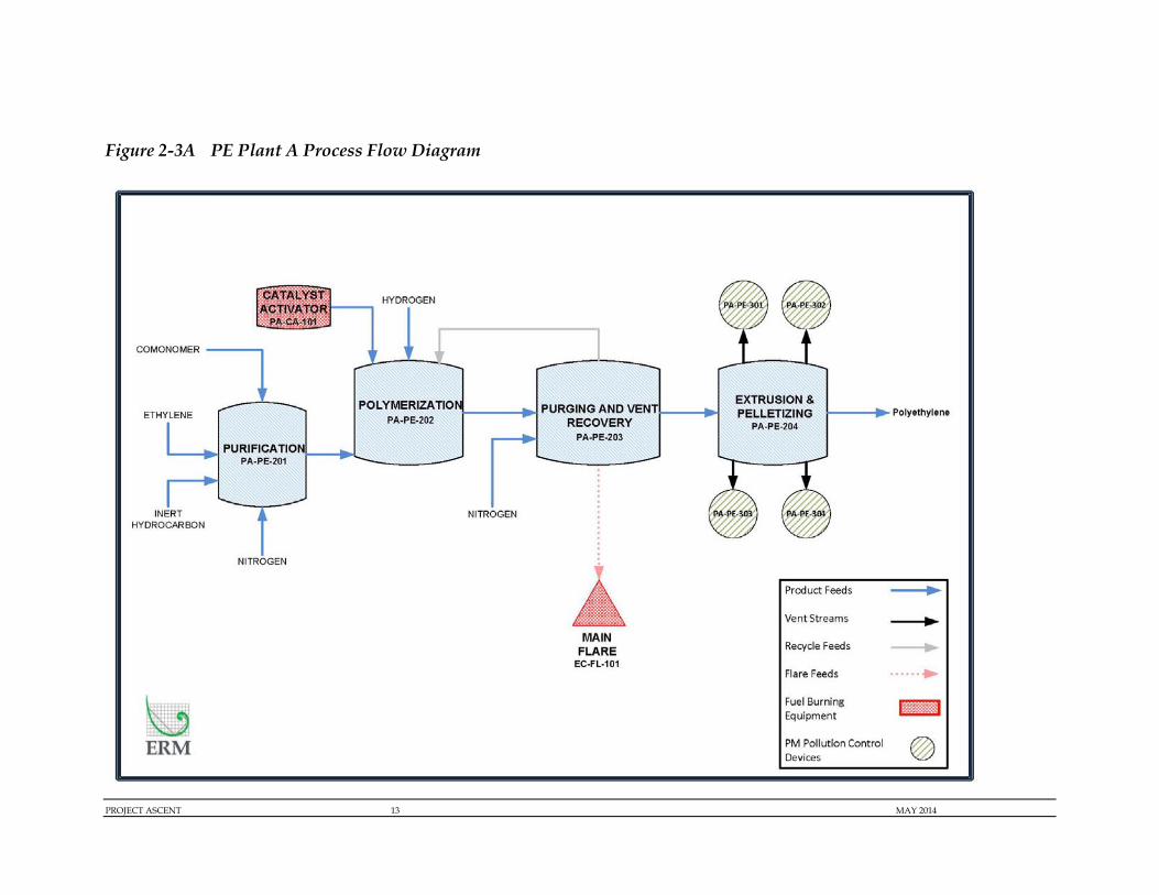
The final polyethylene pellets will be produced by three independent PE plants; Plant A, Plant B, and Plant C. Each plant will utilize a slightly altered manufacturing process to produce three types of polyethylene pellets. The three units will share a common ethylene feed but all other operations will be independent and separate. Each PE plant will be connected to main flare for any unplanned over pressuring event. One Regenerative Thermal Oxidizer (RTO) will be used to treat waste streams generated by Plant C and one low pressure flare will be used control any off-gases generated by Plant B. Figure 2-3A, Figure 2-3B, and Figure 2-3C depict process flow diagrams for each polyethylene plant.
Plant A will consist of four main sections associated with the following operations; purification, polymerization, purging and vent recovery, and extrusion and pelletizing. The purification section will include the use of one natural gas-fired heater, rated at 10 MMBtu/hr, in order to heat up the catalyst to an appropriate temperature. All pellets will be stored in storage silos before being transported offsite via rail or trucks.
Plant B will consist of four main sections associated with the following operations; purification, polymerization, purging and vent recovery, and extrusion and pelletizing. The polymerization section will be comprised of a series of compressors and pumps that will transfer raw ethylene and a comonomer catalyst to the polymerization reactor. After polymerization, the product streams will be sent to purging and vent recovery, to recover all excess hydrocarbon streams. All purged gasses will be sent to the recovery system, where it will be eventually recycled back into the polymerization. All pellets will be stored in storage silos before being transported offsite via rail or trucks.
Plant C will consist of the following operational sections; compression, polymerization, separation, extrusion and pelletizing, pellet handling, and degassing. Ethylene is combined with the catalyst in the compression section before being sent to reactors for polymerization. The product stream is then sent to the separation section to recover excess hydrocarbon streams for recycle. The product stream then undergoes extrusion, pelletizing, and pellet handling before a final degassing section. All pellets will be stored in storage silos before being transported offsite via rail or trucks.

PROJECT ASCENT 12 MAY 2014
2.2.4 Regenerative Thermal Oxidizer (RTO)
One Regenerative Thermal Oxidizer (RTO) will be constructed to treat gas streams generated by Plant C operations. The RTO will destruct excess hydrocarbon gas emissions. The gas streams sent to the RTO will originate from Plant C’s waste oil storage and extrusion section. The RTO will treat the streams through high temperature oxidation. A natural gas burner, with a maximum rating of 20 MMBtu/hr will be designed to supply the start-up heat and the heat necessary to sustain high enough temperatures for the oxidation chamber. After passing through the oxidation chamber, the purified air will be emitted through a stack to the atmosphere.
The RTO will be equipped with a Low NOx Burner and at a minimum, will have a DRE of 99% for all VOC and organic HAP constituents.
2.2.5 Polyethylene Plant Flares
The three polyethylene plants will all be connected to the main flare for the entire facility in the event of any unplanned over pressuring event. A low pressure flare will be constructed to control any flammable gases generated from the Plant B storage silos. The low pressure flare will be designed with a natural gas pilot and a backup pilot, with a total heat input of 0.4 MMBtu/hr. The flare will have a 98% DRE for all gas streams sent to the flare for combustion.
2.2.6 Material Handling Operations
Particulate emissions can occur from material handling operations at any of the three polyethylene plants including, but not limited to, the following operations: extrusion, silo storage, additive feed, additive tanks, blending, and loading. Control of these emissions will be obtained through the use cyclones, baghouses, fabric filters or equivalent controls with an expected DRE greater than 99.9 percent or have an exhaust particulate concentration of less than 0.01 grain/scf. Best management practices for controlling particulate matter will be implemented.
PROJECT ASCENT 13 MAY 2014
Figure 2-3A PE Plant A Process Flow Diagram

PROJECT ASCENT 14 MAY 2014
Figure 2-3B PE Plant B Process Flow Diagram

PROJECT ASCENT 15 MAY 2014
Figure 2-3C PE Plant C Process Flow Diagram

PROJECT ASCENT 16 MAY 2014
2.3 SUPPORT UTILITIES
2.3.1 Power Generation
The Project includes the construction and operation of one on site combustion turbine that will supply some or all of the necessary electricity for the facility. The plant will generate electricity by one natural gas fired GE 7EA combustion turbine, rated at 942.6 MMBtu/hr and an additional Heat Recovery Steam Generation (HRSG) unit, equipped with a steam turbine. An additional duct burner will be constructed for optional firing at a heat input of 346 MMBtu/hr. The HRSG unit will help recover heat from the combustion turbine exhaust gas and produce steam, which is sent to the steam turbine generator to produce additional electric power output. The combustion turbine and the HRSG duct burner will share a common stack and will be equipped with a Selective Catalytic Reduction (SCR) system, at 80% control efficiency, to control all nitrogen oxide (NOx) emissions. The combustion turbine will also incorporate a dry low-NOx combustor into the final design. The SCR involves the injection of aqueous ammonia (NH3) into the exhaust gas streams. The ammonia reacts with NOx in the exhaust gas streams and reduces it to elemental nitrogen (N2) and water vapor (H2O). The aqueous ammonia will be stored on site in storage tanks. The aqueous ammonia storage tanks will not normally vent to the atmosphere. They will be equipped with pressure relief valves that will only vent to atmosphere in the event of an emergency.
An oxidation catalyst will also be used to control carbon monoxide (CO) and volatile organic compounds (VOC) emissions from the combustion turbine and HRSG combined. The oxidation catalyst will have a CO DRE of at least 80%. The combustion turbine and HRSG are assumed to operate continuously (8,760 hr/yr).
2.3.2 Auxiliary Boilers
Two natural gas-fired auxiliary boilers, each with a 206 MMBtu/hr rating, will be constructed and operated continuously (8,760 hr/yr) to supply any additional heat needed for operations at the ASCENT facility. The auxiliary boilers will be equipped with Ultra Low NOx Burners to control emissions.

PROJECT ASCENT 17 MAY 2014
2.3.3 Storage Tanks
The proposed facility will utilize a number of storage tanks for solid, liquid, and gaseous storage for process operations and material storage. The material stored in each tank will include, but not be limited to, caustic soda, sulfuric acid, 1-hexene, raw pyrolysis gas, ethane, propylene, inert hydrocarbons (e.g., isopentane), comonomers (e.g., vinyl acetate), diesel fuel, wastewater, ammonia, and compressor wash oil. A number of the storage tanks will be pressurized and will not have any associated emissions. All volatile organic liquids are controlled by either the cold flare or warm flare with a 98% VOC DRE. Storage tanks containing volatile liquids with a maximum true vapor pressure at storage conditions greater than or equal to 76.6 kPa will be provided with a closed vent system and control devices.
2.3.4 Cooling Tower
A wet, mechanical draft Cooling Tower will be used. Make-up water is added to the Cooling Tower as necessary to account for water evaporation. High efficiency drift eliminators are used to control particulate matter (PM) emissions from the Cooling Tower, with a maximum drift rate of 0.0005% of the total circulation rate.
The make-up cooling water for the Cooling Tower will come from the adjacent Ohio River. The Cooling Tower will operate continuously.
2.3.5 Wastewater Treatment Plant
The WWTP can be divided into three blocks: wastewater collection, effluent treatment plant (ETP), and waste reuse system and final discharge. All wastewater streams will be transferred by means of collection and lifting systems (effluent basins and pumping stations). All effluent pumps and equipment will be driven by electrical motors; therefore, they will be dependent on a continuous electricity supply.
A complete process flow diagram is included in Appendix C of the permit application. The ETP will consist of the following main sections:
Primary Treatment (De-Oiling and Chemical-Physical (CPI) Treatment);
Secondary Treatment (Biological Treatment);

PROJECT ASCENT 18 MAY 2014
Sludge Dewatering;
Treated Water Reuse;
Salt Concentration (Optional); and
Sludge Drying.
The ETP is fed by seven separate influent streams: oily wastewater from the Cracker Plant, cooling water blow-down streams, pretreated spent caustic, flare hydraulic seal from outside battery limits, wastewater from warehouse and workshop facility, sanitary sewage, and oily rain water. The CPI receives all wastewater influent streams except the sanitary sewage. Oily water influents are first collected in an open sump before transfer to the CPI. During peak flows or rain events, excess flows are diverted to the oily water storage tanks where cooling water blow-down is also stored. The oily water storage tanks aid in flow equalization to prevent surge through the CPI.
Once oil is separated from the water in the CPI, skimmed oil is collected for disposal, sludge is sent to the sludge drying unit, and wastewater is routed to the dissolved air flotation (DAF). A coagulant is added in a mixing zone at the start of the DAF unit to promote solids removal. Sludge collected from the DAF is skimmed and sent to the sludge drying unit. Wastewater from the DAF is sent to an equalization tank prior to entering biological treatment. Sanitary sewage is introduced at the biological treatment system. A two-stage biological treatment system is utilized, aerated biological treatment and membrane biological reactor (MBR). Sludge from the MBR is sent to the sludge drying unit. The final treated effluent from the MBR is discharged to the river. Fugitive emissions from the wastewater treatment plant are discussed in Section 3.5.5.
2.3.6 Emergency Generators
The proposed facility will include the use up to nine (9) emergency generators to act as a backup energy supply. There will be seven (7) generators rated at 2800 kW and two (2) generators rated at 350 kW. The Ethane Cracker Plant and each polyethylene plant will have one dedicated 2800 kW emergency generator. The other 2800 kW emergency generators are meant to support the combustion turbine, boilers, and wastewater treatment plant. All nine generators are fired on Ultra Low Sulfur Diesel (ULSD) fuel with a maximum sulfur content of 15 ppm. The smaller 350

PROJECT ASCENT 19 MAY 2014
kW generators will act as a backup power supply for utility operations such as product storage and the cooling water area.
The emergency generators will only be used for unplanned emergencies or power curtailment and will be limited to 100 hours of non-emergency use for maintenance and testing.
2.3.7 Fire Water Pump Engines
The proposed facility will include three (3) emergency Fire Water Pump engines associated with the planned fire water suppression system. The emergency engines will have a maximum rating of 485 kW and will burn ULSD. The engines will be limited to 100 hours of non-emergency use (e.g., maintenance and testing).
2.3.8 Loading Racks
Bulk loading racks will be used for the loading and unloading of all material for the proposed facility. The loading racks will control VOC and HAPS emissions using the cold flare or warm flare depending on the type of liquid transfer. Cold and warm liquid storage will be managed via separate loading/unloading racks.
PROJECT ASCENT 20 MAY 2014
3.0 PROJECT EMISSIONS
3.1 OVERVIEW AND METHODOLOGY
Potential emissions from new and modified sources in attainment areas are evaluated through the New Source Review (NSR) Prevention of Significant Deterioration (PSD) program. The Project’s potential air emissions were evaluated to ensure that the Project would meet all applicable regulatory thresholds and limits.
Potential air emissions for this application were estimated using various calculation methodologies including vendor provided data specifications, EPA, State agency or industry specific emission factors (e.g., US EPA’s Compilation of Air Pollutant Emission Factors (AP-42) publication), material balances, New Source Performance Standards (NSPS) emission standards, EPA’s Water9 and TANKS 4.09D programs, and/or engineering calculations. Supporting emissions calculations are provided in Appendix D of the permit application. The locations of the point emission sources and primary project components are provided in Figure B-3 and B-4 of Appendix B of the permit application.
3.2 FACILITY WIDE EMISSIONS
The facility wide Potential-to-Emit (PTE) air emissions for all regulated criteria pollutants or their precursors, greenhouse gasses (GHGs), and total hazardous air pollutants (HAPs) can be found in Table 3-1. The subsequent subsections provide a detailed explanation on the methodology used to estimate all potential emissions.
Based on the potential emissions reported in this application, the Project has the potential to be a major PSD source for the following air pollutants:
Nitrogen oxides (NOx);
Carbon Monoxide (CO);
Volatile Organic Compounds (VOCs);
PROJECT ASCENT 21 MAY 2014
Particulate matter (PM/PM10/PM2.5);
HAPs (Hexane and Total); and
GHGs (expressed on a carbon dioxide equivalent (CO2e) basis).
3.2.1 Criteria Pollutants
The USEPA has defined concentration-based NAAQS for several pollutants, which are set at levels considered protective of the public health and welfare. Specifically, the NAAQS have been defined for six (6) “criteria” pollutants, including PM, SO2, CO, nitrogen oxides (NOx), ozone, and lead (Pb). The three (3) forms of particulate matter regulated are total suspended particulate (known as PM), PM10, and PM2.5. The production of Sulfuric Acid Mist (SAM) can also occur from the burning of sulfur containing fuels. Natural gas has a relatively low sulfur content; however, SAM emissions can still be generated. SAM emissions are captured under the PM, PM10, and PM2.5 totals. For all fuel burning equipment, this application conservatively assumes 0.02 grains/scf for short-term sulfur content of natural gas and 0.0022 grains/scf for annual average sulfur content of natural gas.
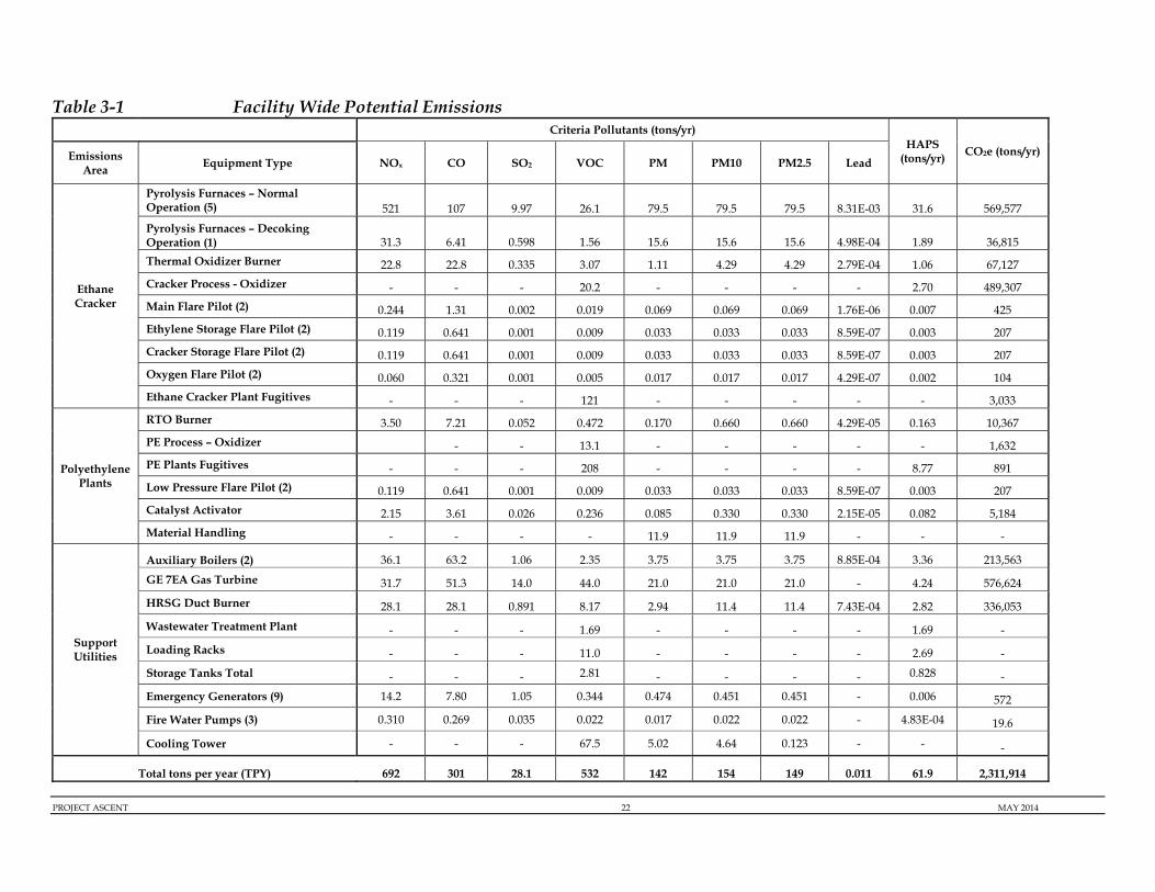
Table 3-1 Facility Wide Potential Emissions
PROJECT ASCENT 22 MAY 2014
Criteria Pollutants (tons/yr) HAPS
(tons/yr) CO2e (tons/yr) Emissions Area
Equipment Type NOx CO SO2 VOC PM PM10 PM2.5 Lead
Ethane Cracker
Pyrolysis Furnaces – Normal Operation (5) 521 107 9.97 26.1 79.5 79.5 79.5 8.31E-03 31.6 569,577
Pyrolysis Furnaces – Decoking Operation (1) 31.3 6.41 0.598 1.56 15.6 15.6 15.6 4.98E-04 1.89 36,815
Thermal Oxidizer Burner 22.8 22.8 0.335 3.07 1.11 4.29 4.29 2.79E-04 1.06 67,127
Cracker Process - Oxidizer - - - 20.2 - - - - 2.70 489,307
Main Flare Pilot (2) 0.244 1.31 0.002 0.019 0.069 0.069 0.069 1.76E-06 0.007 425
Ethylene Storage Flare Pilot (2) 0.119 0.641 0.001 0.009 0.033 0.033 0.033 8.59E-07 0.003 207
Cracker Storage Flare Pilot (2) 0.119 0.641 0.001 0.009 0.033 0.033 0.033 8.59E-07 0.003 207
Oxygen Flare Pilot (2) 0.060 0.321 0.001 0.005 0.017 0.017 0.017 4.29E-07 0.002 104
Ethane Cracker Plant Fugitives - - - 121 - - - - - 3,033
Polyethylene Plants
RTO Burner 3.50 7.21 0.052 0.472 0.170 0.660 0.660 4.29E-05 0.163 10,367
PE Process – Oxidizer - - 13.1 - - - - - 1,632
PE Plants Fugitives - - - 208 - - - - 8.77 891
Low Pressure Flare Pilot (2) 0.119 0.641 0.001 0.009 0.033 0.033 0.033 8.59E-07 0.003 207
Catalyst Activator 2.15 3.61 0.026 0.236 0.085 0.330 0.330 2.15E-05 0.082 5,184
Material Handling - - - - 11.9 11.9 11.9 - - -
Support Utilities
Auxiliary Boilers (2) 36.1 63.2 1.06 2.35 3.75 3.75 3.75 8.85E-04 3.36 213,563
GE 7EA Gas Turbine 31.7 51.3 14.0 44.0 21.0 21.0 21.0 - 4.24 576,624
HRSG Duct Burner 28.1 28.1 0.891 8.17 2.94 11.4 11.4 7.43E-04 2.82 336,053
Wastewater Treatment Plant - - - 1.69 - - - - 1.69 -
Loading Racks - - - 11.0 - - - - 2.69 -
Storage Tanks Total - - - 2.81 - - - - 0.828 -
Emergency Generators (9) 14.2 7.80 1.05 0.344 0.474 0.451 0.451 - 0.006 572
Fire Water Pumps (3) 0.310 0.269 0.035 0.022 0.017 0.022 0.022 - 4.83E-04 19.6
Cooling Tower - - - 67.5 5.02 4.64 0.123 - - -
Total tons per year (TPY) 692 301 28.1 532 142 154 149 0.011 61.9 2,311,914

PROJECT ASCENT 23 MAY 2014
3.2.2 Hazardous Air Pollutant Emissions
Appropriate AP-42 sections provide emission factors for organic and metal compounds resulting from combustion, some of which are HAPs. Estimated HAP emissions from the proposed Project are summarized in Table 3-2. A facility is considered a "major" source of HAPs if it has the potential to emit 10 tpy or more of any individual HAP, or 25 tpy or more of all HAPs combined. As shown in Table 3-10, maximum emissions of any single HAP are 47.5 tpy (hexane), and estimated total HAP emissions from the Project are 61.2 tpy. Because the emissions of hexane exceed 10 tpy and the total HAPs are greater than 25 tpy, the Project is considered a major source of HAPs.
Table 3-2 Hazardous Air Pollutants (HAPS) Potential Emissions
tons/yr
Pollutant Fuel Combustion Tanks
Loading Racks
Waste Combustion WWTP Fugitives
Facility Wide Total
1,3-Butadiene 3.56E-03 - - - - - 3.56E-03
2-Methylnaphthalene 5.18E-04 - - - - - 5.18E-04
3-Methylchloranthrene 3.88E-05 - - - - - 3.88E-05 7,12-Dimethylbenz(a)anthracene 3.45E-04 - - - - - 3.45E-04
Acenaphthene 7.28E-05 - - - - - 5.58E-05
Acenaphthylene 1.06E-04 - - - - - 7.26E-05
Anthracene 6.10E-05 - - - - - 5.64E-05
Acetaldehyde 3.31E-01 - - - - - 0.165
Acrolein 5.29E-02 - - - - - 0.026
Benz(a)anthracene 4.37E-05 - - - - - 4.13E-05
Benzene 0.149 0.548 0.832 2.13 1.69 - 5.30
Benzo(a)pyrene 2.78E-05 - - - - - 2.68E-05
Benzo(b)fluoranthene 4.68E-05 - - - - - 4.28E-05
Benzo(g,h,i)perylene 3.00E-05 - - - - - 2.79E-05
Benzo(k)fluoranthene 4.04E-05 - - - - - 3.96E-05
Butadiene - - 1.40 - - - 1.40
Chrysene 4.99E-05 - - - - - 4.44E-05
Dibenzo(a,h)anthracene 2.85E-05 - - - - - 2.72E-05
Dichlorobenzene 2.59E-02 - - - - - 0.026

PROJECT ASCENT 24 MAY 2014
tons/yr
Pollutant Fuel Combustion Tanks
Loading Racks
Waste Combustion WWTP Fugitives
Facility Wide Total
Ethylbenzene 2.64E-01 0.001 0.017 - - - 0.150
Fluoranthene 9.55E-05 - - - - - 8.01E-05
Fluorene 1.59E-04 - - - - - 1.10E-04
Formaldehyde 7.48E+00 - - - - - 4.55
Hexane 3.88E+01 6.54E-05 - 0.182 - 8.55 47.5
Indeno(1,2,3-cd)pyrene 4.19E-05 - - - - - 4.03E-05
Naphthalene 2.48E-02 - - - - - 0.019
Methanol 0.00E+00 - - - - 0.220 2.20E-01
Phenanathrene 6.67E-04 - - - - - 5.17E-04
Phenol 0.00E+00 - - - 4.27E-04 - 4.27E-04
Propylene Oxided 2.39E-01 - - - - - 0.120
Pyrene 1.36E-04 - - - - - 1.22E-04
Styrene - 0.003 0.083 0.125 - - 0.211
Toluene 1.15E+00 0.023 0.125 0.258 - - 1.02
Vinyl Acetate 0.00E+00 0.251 0.220 - - - 0.472
Arsenic 4.31E-03 - - - - - 4.31E-03
Barium 9.49E-02 - - - - - 0.095
Beryllium 2.59E-04 - - - - - 2.59E-04
Cadmium 2.37E-02 - - - - - 0.024
Chromium 3.02E-02 - - - - 6.89E-06 0.030
Cobalt 1.81E-03 - - - - - 1.81E-03
Copper 1.83E-02 - - - - - 0.018
Manganese 8.19E-03 - - - - - 8.19E-03
Mercury 5.61E-03 - - - - - 5.61E-03
Molybdenum 2.37E-02 - - - - - 0.024
Nickel 4.53E-02 - - - - - 0.045
Selenium 5.18E-04 - - - - - 5.18E-04
Vanadium 4.96E-02 - - - - - 0.050
Xylenes 5.30E-01 1.04E-03 1.66E-02 7.72E-03 - - 0.290
Zinc 6.25E-02 - - - - - 0.063
TOTAL PAH 1.97E-02 - - - 2.17E-05 - 9.89E-03
Total HAPS (tpy) 61.9

PROJECT ASCENT 25 MAY 2014
3.2.3 Greenhouse Gas Emissions
Potential GHG emissions [i.e., CO2, methane (CH4) and nitrous oxide (N2O)] were estimated for all combustion sources associated with the Project. GHG emissions on an individual and carbon dioxide equivalent (CO2e) basis are summarized in Table 3-3. In 40 CFR 98, USEPA defines CO2e emissions to be equivalent to CO2 emissions plus 25 times the CH4 emissions plus 298 times the N2O emissions, utilizing the applicable Global Warming Potentials (GWPs).
Table 3-3 Greenhouse Gases Potential Emissions
CO2e (tons/yr)
Primary GHGs (tons/yr)
Emissions Area Equipment Type
Carbon Dioxide
(CO2)
Methane (CH4)
Nitrous Oxide (N2O)
Ethane Cracker
Pyrolysis Furnaces – Normal Operation (5) 569,577 565,453 38.2 10.63
Pyrolysis Furnaces – Decoking Operation (1) 36,815 36,567 2.29 0.64
Thermal Oxidizer Burner 67,127 66,988 1.28 0.36
Cracker Process - Oxidizer 489,307 489,307 - -
Main Flare Pilot (2) 425 423 0.008 0.008
Ethylene Storage Flare Pilot (2) 207 206 0.004 0.004
Cracker Storage Flare Pilot (2) 207 206 0.004 0.004
Oxygen Flare Pilot (2) 104 103 0.002 0.002
Ethane Cracker Plant Fugitives 3,033 - 121 -
Polyethylene Plants
RTO Burner 10,367 10,306 0.20 0.19
PE Process – Oxidizer 1,632 1,632 - -
PE Plant Fugitives and Flares 891 - 35.6 -
Low Pressure Flare Pilot (2) 207 206 0.004 0.004
Catalyst Activator 5,184 5,153 0.099 0.094
Material Handling - - - -
Support Utilities
Auxiliary Boilers (2) 213,563 212,301 4.07 3.89
GE 7EA Gas Turbine 576,624 572,834 3.96 12.39
HRSG Duct Burner 336,053 332,258 140.5 0.95
Wastewater Treatment System - - - -
Loading Racks - - - -
Storage Tanks Total - - - -
Emergency Generators (9) 572 571.56 0.03 -
PROJECT ASCENT 26 MAY 2014
CO2e
(tons/yr)
Primary GHGs (tons/yr)
Emissions Area Equipment Type
Carbon Dioxide
(CO2)
Methane (CH4)
Nitrous Oxide (N2O)
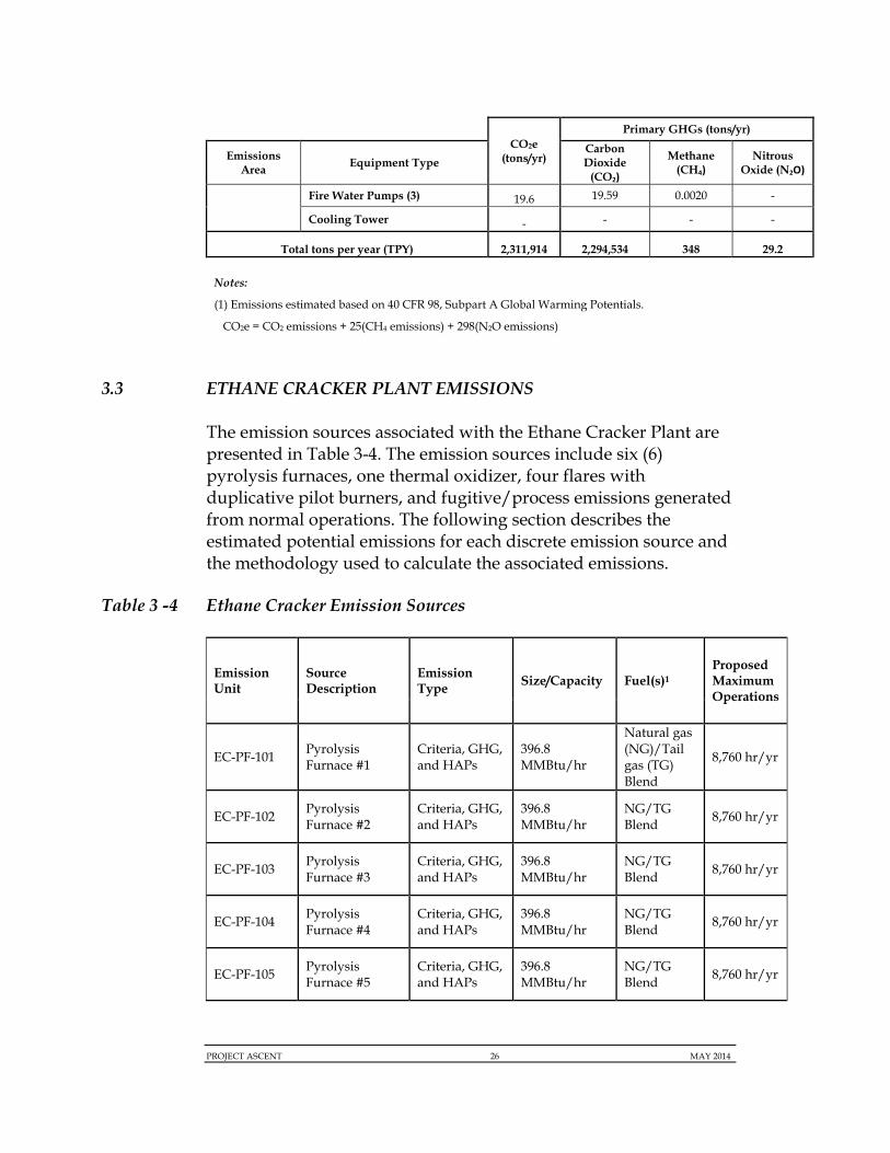
Fire Water Pumps (3) 19.6 19.59 0.0020 -
Cooling Tower - - - -
Total tons per year (TPY) 2,311,914 2,294,534 348 29.2
Notes:
(1) Emissions estimated based on 40 CFR 98, Subpart A Global Warming Potentials.
CO2e = CO2 emissions + 25(CH4 emissions) + 298(N2O emissions)
3.3 ETHANE CRACKER PLANT EMISSIONS
The emission sources associated with the Ethane Cracker Plant are presented in Table 3-4. The emission sources include six (6) pyrolysis furnaces, one thermal oxidizer, four flares with duplicative pilot burners, and fugitive/process emissions generated from normal operations. The following section describes the estimated potential emissions for each discrete emission source and the methodology used to calculate the associated emissions.
Table 3 -4 Ethane Cracker Emission Sources
Emission Unit
Source Description
Emission Type Size/Capacity Fuel(s)1
Proposed Maximum Operations
EC-PF-101 Pyrolysis Furnace #1
Criteria, GHG, and HAPs
396.8 MMBtu/hr
Natural gas (NG)/Tail gas (TG) Blend
8,760 hr/yr
EC-PF-102 Pyrolysis Furnace #2
Criteria, GHG, and HAPs
396.8 MMBtu/hr
NG/TG Blend
8,760 hr/yr
EC-PF-103 Pyrolysis Furnace #3
Criteria, GHG, and HAPs
396.8 MMBtu/hr
NG/TG Blend
8,760 hr/yr
EC-PF-104 Pyrolysis Furnace #4
Criteria, GHG, and HAPs
396.8 MMBtu/hr
NG/TG Blend
8,760 hr/yr
EC-PF-105 Pyrolysis Furnace #5
Criteria, GHG, and HAPs
396.8 MMBtu/hr
NG/TG Blend
8,760 hr/yr

PROJECT ASCENT 27 MAY 2014
Emission Unit
Source Description
Emission Type Size/Capacity Fuel(s)1
Proposed Maximum Operations
EC-PF-106 Pyrolysis Furnace #6
Criteria, GHG, and HAPs
119 MMBtu/hr
NG/TG Blend
8,760 hr/yr
EC-TO-101 Cracker Thermal Oxidizer
Criteria, GHG, and HAPs
130 MMBtu/hr
NG 8,760 hr/yr
EC-PE-101 Cracker Process - Oxidizer Emissions
VOC, GHG 2,097 kg/hr2 N/A 8,760 hr/yr
EC-PE-102
Cracker Process- Fugitive Emissions
VOC, GHG N/A N/A 8,760 hr/yr
EC-FL-101 Main Flare Pilots
Criteria, GHG, and HAPs
0.82 MMBtu/hr total
NG 8,760 hr/yr
EC-FL-102 Ethylene Storage (Cold) Flare Pilots
Criteria, GHG, and HAPs
0.4 MMBtu/hr total
NG 8,760 hr/yr
EC-FL-103 Storage Flare Pilots
Criteria, GHG, and HAPs
0.4 MMBtu/hr total
NG 8,760 hr/yr
EC-FL-104 Oxygen Flare Pilots
Criteria, GHG, and HAPs
0.2 MMBtu/hr total
NG 8,760 hr/yr
Notes:
(1) Fuels used for the equipment will largely be pipeline quality natural gas (NG) with the exception of the six
cracking furnaces, which will use a combination of NG and recycled tail gas (TG).
(2) Waste inlet flow rates for the cracker thermal oxidizer are based on a conservative estimate for the normal
continuous flow plus the intermittent gasoline max flow.
3.3.1 Pyrolysis Furnaces (Normal Operation and Decoking)
The potential emissions for NOx, CO, PM, CO2, and VOC from the six pyrolysis furnaces were calculated based on vendor specified emission data for Ultra-Low NOx Burners (ULNBs). All other remaining emissions were calculated based on AP-42 Chapter 1.4 emission factors for natural gas or more stringent BACT determinations where applicable. All PM emissions are assumed to be less than 1.0 micron in aerodynamic diameter.
During normal operations, five furnaces will be fired at total heat input of 1,984 MMBtu/hr and one furnace will be held on hot
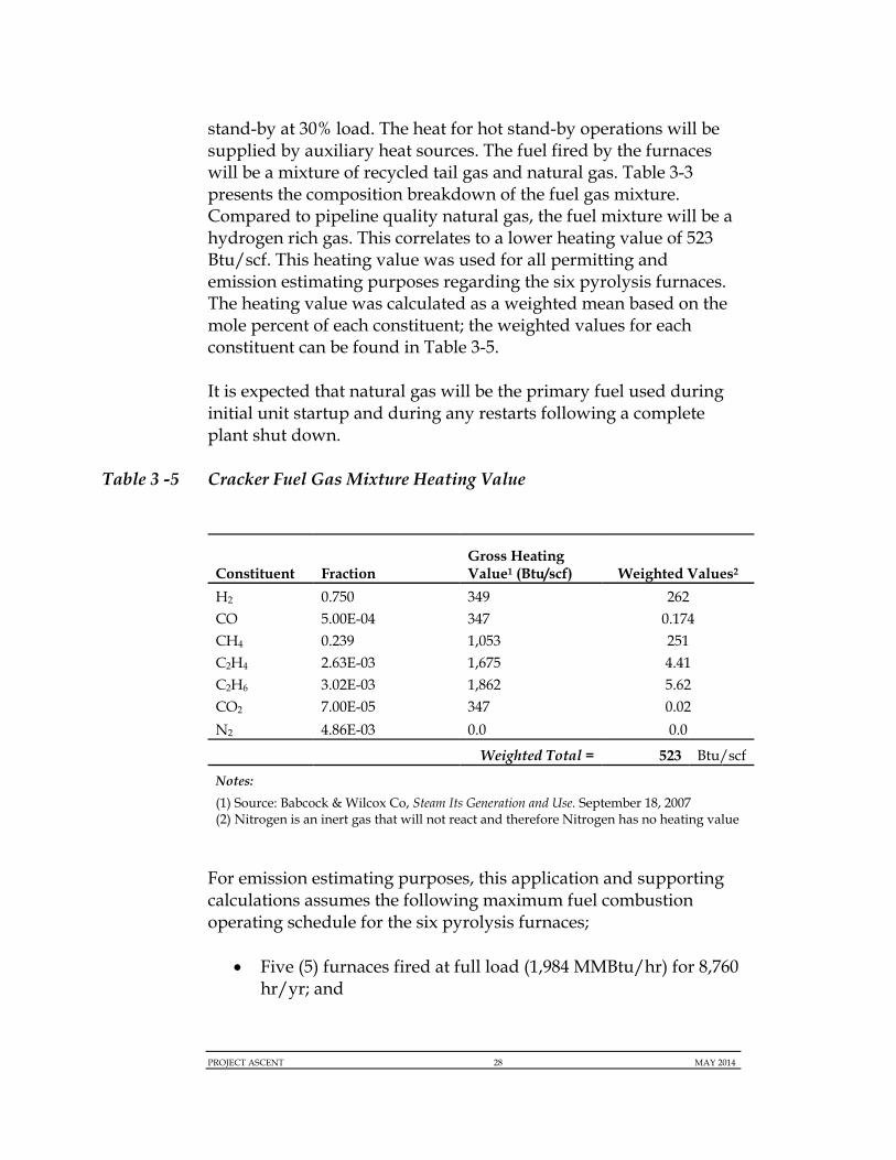
PROJECT ASCENT 28 MAY 2014
stand-by at 30% load. The heat for hot stand-by operations will be supplied by auxiliary heat sources. The fuel fired by the furnaces will be a mixture of recycled tail gas and natural gas. Table 3-3 presents the composition breakdown of the fuel gas mixture. Compared to pipeline quality natural gas, the fuel mixture will be a hydrogen rich gas. This correlates to a lower heating value of 523 Btu/scf. This heating value was used for all permitting and emission estimating purposes regarding the six pyrolysis furnaces. The heating value was calculated as a weighted mean based on the mole percent of each constituent; the weighted values for each constituent can be found in Table 3-5.
It is expected that natural gas will be the primary fuel used during initial unit startup and during any restarts following a complete plant shut down.
Table 3 -5 Cracker Fuel Gas Mixture Heating Value
Constituent Fraction Gross Heating Value1 (Btu/scf) Weighted Values2
H2 0.750 349 262 CO 5.00E-04 347 0.174 CH4 0.239 1,053 251 C2H4 2.63E-03 1,675 4.41 C2H6 3.02E-03 1,862 5.62 CO2 7.00E-05 347 0.02
N2 4.86E-03 0.0 0.0
Weighted Total = 523 Btu/scf
Notes:
(1) Source: Babcock & Wilcox Co, Steam Its Generation and Use. September 18, 2007 (2) Nitrogen is an inert gas that will not react and therefore Nitrogen has no heating value
For emission estimating purposes, this application and supporting calculations assumes the following maximum fuel combustion operating schedule for the six pyrolysis furnaces;
Five (5) furnaces fired at full load (1,984 MMBtu/hr) for 8,760 hr/yr; and
PROJECT ASCENT 29 MAY 2014
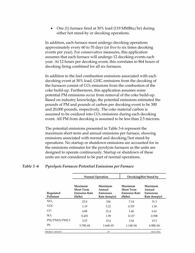
One (1) furnace fired at 30% load (119 MMBtu/hr) during either hot stand-by or decoking operations.
In addition, each furnace must undergo decoking operations approximately every 60 to 70 days (or five to six times decoking events per year). For conservative measures, this application assumes that each furnace will undergo 12 decoking events each year. At 12 hours per decoking event, this correlates to 864 hours of decoking firing combined for all six furnaces.
In addition to the fuel combustion emissions associated with each decoking event at 30% load, GHG emissions from the decoking of the furnaces consist of CO2 emissions from the combustion of the coke build-up. Furthermore, this application assumes some potential PM emissions occur from removal of the coke build-up. Based on industry knowledge, the potential emissions estimated the pounds of PM and pounds of carbon per decoking event to be 300 and 20,000 pounds, respectively. The coke material carbon is assumed to be oxidized into CO2 emissions during each decoking event. All PM from decoking is assumed to be less than 2.5 microns.
The potential emissions presented in Table 3-6 represent the maximum short term and annual emissions per furnace, showing emissions associated with normal and decoking/hot stand-by operations. No startup or shutdown emissions are accounted for in the emissions estimates for the pyrolysis furnaces as the units are designed to operate continuously. Startup or shutdown of these units are not considered to be part of normal operations.
Table 3 -6 Pyrolysis Furnaces Potential Emissions per Furnace
Normal Operation Decoking/Hot Stand-by
Regulated Pollutant
Maximum Short Term Emission Rate (lb/hr)
Maximum Annual Emissions Rate (tons/yr)
Maximum Short Term Emission Rate (lb/hr)
Maximum Annual Emissions Rate (tons/yr)
NOx 23.8 104 7.14 31.3 VOC 1.19 5.21 0.357 1.56 CO 4.88 21.4 1.46 6.41 SO2 0.455 1.99 0.137 0.598 PM/PM10/PM2.5 3.57 15.6 3.54 15.5 Pb 3.79E-04 1.66E-03 1.14E-04 4.98E-04
PROJECT ASCENT 30 MAY 2014
SAM 0.061 0.267 0.018 0.080 CO2e 26,008 113,915 8,405 36,815
3.3.2 Ethane Cracker Plant Thermal Oxidizer
The Ethane Cracker Plant Thermal Oxidizer will be designed with a radiant section, for the combustion of waste in-let streams, and a natural gas burner rated at 130 MMBtu/hr. The emissions generated from the unit are twofold; emissions generated from natural gas combustion and emissions generated from the waste combustion. The natural gas burner will be equipped with Low NOx Burners (LNBs) and the radiant section will be designed to have a 99.9% DRE for all VOCs and organic HAPS. The thermal oxidizer will receive a normal continuous feed comprised of water containing 1-hexene and C10/C11 compounds. In addition to the continuous waste streams, intermittent waste streams from the Ethane Cracker will be sent to the oxidizer for reduction that will include, wash oil from the CGC, pyrolysis gasoline, and peak water. The compositions of the streams sent to the thermal oxidizer are included with the emissions calculations provided in Appendix D of the permit application.
The emissions associated with the natural gas burner were calculated based on AP-42 Chapter 1.4 emission factors. The emissions associated with the radiant section were calculated based on a material balance for inlet waste flow rates. All organic waste constituents are assumed to be oxidized to CO2 at a 99.9% efficiency. The maximum operating schedule was assumed 8,760 hr/yr for both the fuel and waste combustion. Table 3-7 presents the combined emissions associated with both the fuel and waste combustion. Waste inlet flow rates for the oxidizer are based on a conservative estimate considering a continuous flow of both the normal operations flow plus the pyrolysis gasoline flow (which is typically an intermittent stream). The pyrolysis gasoline intermittent stream was selected because of the higher content of VOCs.
Table 3-7 Thermal Oxidizer Potential Emissions

PROJECT ASCENT 31 MAY 2014
Regulated Pollutant
Maximum Short Term Emission Rate (lb/hr)
Maximum Annual Emissions Rate (tons/yr)
NOx 5.20 22.8 VOC 5.32 23.3 CO 5.20 22.8 SO2 0.076 0.335 PM (filterable) 0.242 1.06 PM10/PM2.5 (total) 0.969 4.24 Pb 6.37E-05 2.79E-04
SAM 0.010 0.045 CO2e 127,040 556,434
Notes: (0) Combined emissions for fuel and waste combustion
3.3.3 Ethane Cracker Plant Fugitive Emissions
Fugitive emissions generated by Ethane Cracker Plant originate from equipment leaks associated the total number of seals, valves, and connection points within the entire Ethane Cracker Plant. Emission factors and control efficiencies are based on the EPA Protocol for Equipment Leak Emission Estimates (SOCMI) and were used to estimate all potential fugitive VOC leak emissions. The SOCMI emissions factors are conservative and should be considered uncontrolled fugitive emissions with a leak detection of 10,000 ppmv. However, the proposed Project will be subject to Leak Detection and Repair (LDAR) requirements under 40 CFR Part 60 Subpart VVa. ASCENT’s review of resources addressing the control of emissions identified the Texas Commission of Environmental Quality (TCEQ). Due to the large number of chemical plants in Texas, the State has developed a series of guidance documents addressing common emission sources including an in-State regulatory LDAR program, similar to the Subpart Vva requirements. As such, each component type was assigned a control efficiency based on the Control Efficiencies for TCEQ Leak Detection and Repair Programs (28VHP) guidance document. For example, valves in a heavy liquid service may be given a 97% reduction credit if monitored at 500 ppmv.
For emission estimating purposes, all equipment contents are conservatively assumed to be 100% VOC and are assumed to

PROJECT ASCENT 32 MAY 2014
operate at 8,760 hr/yr. To estimate GHG emissions, all VOCs were assumed to be equivalent to methane (CH4). Table 3-8 presents the short term and annual fugitive emissions associated with the Ethane Cracker Plant.
Table 3-8 Ethane Cracker Plant Fugitives Potential Emissions
Emission Source
Maximum Short Term Emission Rate 1 (lb/hr)
Maximum Annual Emissions Rate 1 (tons/yr)
Seals/Pumps 1.60 7.02 Valves 2.62 11.5
Connections 23.5 103
Total 27.7 121
Notes: (1) The total amount of hydrocarbon leaks from the process were used to calculate both total VOC emissions and total GHG emissions (from methane). The total CO2e emissions from fugitives are estimated at 25 times the value of the methane total emissions based on EPA’s Global Warming Potential factors approved in 40 CFR Part 98.
3.3.4 Ethane Cracker Plant Flare Emissions
The emissions generated by the main flare, ethylene storage flare, product storage flare, and oxygen flare pilot systems associated with the Ethane Cracker Plant, were estimated based on emission factors derived from AP-42 Chapter 1.4 for natural gas external combustion. All flare pilots were assumed to operate at 8,760 hr/yr. Startup and shutdown of the flare pilots is considered outside of normal operations.
3.4 POLYETHYLENE PLANTS EMISSIONS
The emission sources associated with the three PE plants are presented in Table 3-9. The following section describes the estimated potential emissions for each emission source associated with the three PE plants and the methodology used to calculate all emissions. Fuel burning equipment associated with the PE plants include the RTO burner; the catalyst activator; and the gas pilot associated with the low pressure flare.

PROJECT ASCENT 33 MAY 2014
In addition to fuel burning equipment, each of the three plants will have associated vent and fugitives emissions (VOCs) and material handling emissions (PM) discussed more below.
Table 3 -9 Polyethylene Plants Emission Sources
Emission Unit
Source Description
Emission Type Size/Capacity Fuel(s) Proposed Maximum Operations
PC-TO-102 Regenerative Thermal Oxidizer
Criteria, GHG, and HAPS
20 MMBtu/hr NG 8,760 hr/yr
PB-FL-105 Low Pressure Flare Pilots
Criteria, GHG, and HAPS
0.4 MMBtu/hr total
NG 8,760 hr/yr
PA-CA-101 Catalyst Activator
Criteria, GHG, and HAPS
10 MMBtu/hr NG 8,760 hr/yr
PC-PE-103 Process – Oxidizer Emissions
VOC and CO2 136.0 kg/hr1 N/A 8,760 hr/yr
PA-FE-101 PE Plant A Fugitive/Vent Emissions
VOC, PM, NOx, CO (Fugitive/vents)
N/A N/A 8,760 hr/yr
PC-FE-101 PE Plant C Fugitive/Vent Emissions
VOC, PM, NOx, CO (Fugitive/vents)
N/A N/A 8,760 hr/yr
PB-FE-101 PE Plant B Fugitives/Vent Emissions
VOC, PM, NOx, CO (Fugitive/vents)
N/A N/A 8,760 hr/yr
PA-MH-101
PE Plant A Material Handling Emissions
PM N/A N/A Varies
PB-MH-101
PE Plant B Material Handling Emissions
PM N/A N/A Varies
PC-MH-101
PE Plant C Material Handling Emissions
PM N/A N/A Varies
Notes:
(1) Inlet flow rates for the RTO are based on maximum waste flow rates from both the extrusion/pelletizing
and waste oil storage sections.
PROJECT ASCENT 34 MAY 2014
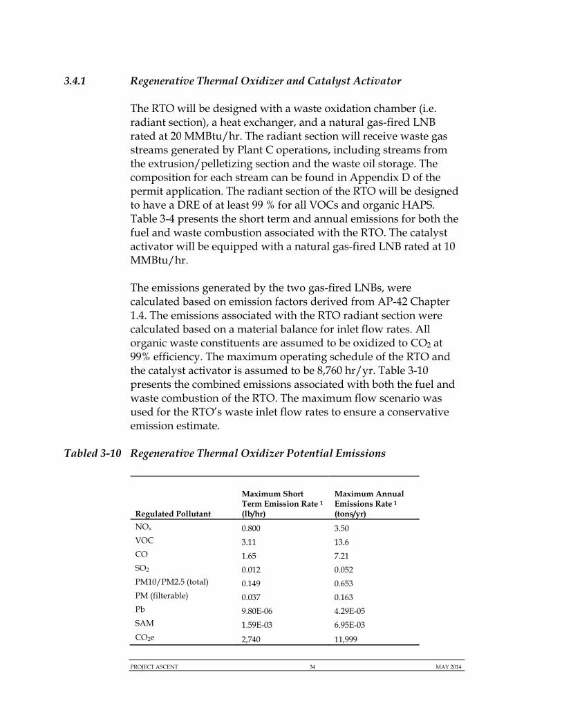
3.4.1 Regenerative Thermal Oxidizer and Catalyst Activator
The RTO will be designed with a waste oxidation chamber (i.e. radiant section), a heat exchanger, and a natural gas-fired LNB rated at 20 MMBtu/hr. The radiant section will receive waste gas streams generated by Plant C operations, including streams from the extrusion/pelletizing section and the waste oil storage. The composition for each stream can be found in Appendix D of the permit application. The radiant section of the RTO will be designed to have a DRE of at least 99 % for all VOCs and organic HAPS. Table 3-4 presents the short term and annual emissions for both the fuel and waste combustion associated with the RTO. The catalyst activator will be equipped with a natural gas-fired LNB rated at 10 MMBtu/hr.
The emissions generated by the two gas-fired LNBs, were calculated based on emission factors derived from AP-42 Chapter 1.4. The emissions associated with the RTO radiant section were calculated based on a material balance for inlet flow rates. All organic waste constituents are assumed to be oxidized to CO2 at 99% efficiency. The maximum operating schedule of the RTO and the catalyst activator is assumed to be 8,760 hr/yr. Table 3-10 presents the combined emissions associated with both the fuel and waste combustion of the RTO. The maximum flow scenario was used for the RTO’s waste inlet flow rates to ensure a conservative emission estimate.
Tabled 3-10 Regenerative Thermal Oxidizer Potential Emissions
Regulated Pollutant
Maximum Short Term Emission Rate 1
(lb/hr)
Maximum Annual Emissions Rate 1 (tons/yr)
NOx 0.800 3.50 VOC 3.11 13.6 CO 1.65 7.21 SO2 0.012 0.052 PM10/PM2.5 (total) 0.149 0.653 PM (filterable) 0.037 0.163 Pb 9.80E-06 4.29E-05 SAM 1.59E-03 6.95E-03 CO2e 2,740 11,999

PROJECT ASCENT 35 MAY 2014
Notes: (1) Combined emissions for fuel and waste combustion
3.4.2 Polyethylene Plants Fugitive and Flare Emissions
All three PE plants will be connected to the main flare for any unplanned over pressuring events. Emergency events are not predictable and emissions for these types of occurrences are not considered in the facility potential to emit. Normal operation (continuous or intermittent) venting can occur from each PE plant. These emissions are discussed below.
Plant A vent streams are sent to the main flare for a control efficiency of 98 %. There is no alternative dedicated control device for Plant A. Waste streams generated by Plant C operations will be sent to the RTO, which will be designed to have a DRE of 99 %, to capture non-continuous off-gassing events that cannot return to the ethane cracker plant due to high oxygen content. These emissions are captured in the RTO discussion. Because the product stream for the Plant C process is primarily ethylene, any upsets in this process are typically recycled back to the furnaces as an acceptable fuel. Plant B will be equipped with a flare to control low pressure vent emissions at a 98 % control efficiency. In the event the low pressure flare is out of service, Plant B can bypass the low pressure flare and utilize the main flare.
Each plant may also generate fugitive emissions that occur from unit operations. Fugitive emissions are emitted directly to the atmosphere under off-gassing operations.
Table 3-11 presents the total fugitive and vent emissions for all three polyethylene plants not already captured from the RTO emissions.
Table 3-11 Polyethylene Plants Fugitive Emissions
Regulated Pollutant
Plant A (tons/yr)
Plant C (tons/yr)
Plant B (tons/yr)
Total (tons/yr)
VOC 184 11.4 12.3 207.7
HAPS 8.77 - - 8.77
CO2e 577 5.68 308 891

PROJECT ASCENT 36 MAY 2014
Notes: (1) For some streams, a portion of the material was only defined as hydrocarbons. For these cases, the total amount of hydrocarbon leaks from the process were used to calculate both total VOC emissions and total GHG emissions (from methane).
3.4.3 Low Pressure Flare Emissions
The emissions generated by the low pressure flare pilots, associated with Plant B, were estimated based on emission factors derived from AP-42 Chapter 1.4 for natural gas combustion. The flare pilots are assumed to operate 8,760 hr/yr.
3.4.4 Polyethylene Plant Material Handling Operations
The operation of the PE plants requires the transfer of solid materials. Material handling operations of solids generate PM emissions. The material handling emissions from these processes will be controlled by baghouses and/or fabric filters with a 0.01 gr/scf control. The primary areas of material handling include additive transfer and extrusion/pelleting operations. Plant A has a potential of 10.6 tpy PM emissions. The material handling emissions from the other PE plants are less than one tpy.
3.5 SUPPORT UTILITIES EMISSIONS
The emission sources associated the support utility operations are presented in Table 3-12. The following section describes the estimated potential emissions for each source and the methodology used to calculate all emissions. The support utilities include the combustion turbine, auxiliary boilers, cooling tower, emergency generators, and emergency fire water pump engines.
Table 3 -12 Support Utility Emission Sources
Emission Unit
Source Description Emission Type Size/Capacity Fuel(s)
Proposed Maximum Operations
SU-GT-101 GE 7EA Gas Turbine
Criteria, GHG, and HAPS
942.6 MMBtu/hr
NG 8,760 hr/yr

PROJECT ASCENT 37 MAY 2014
Emission Unit
Source Description Emission Type Size/Capacity Fuel(s)
Proposed Maximum Operations
SU-GT-102 HRSG Duct Burner
Criteria, GHG, and HAPS
350 MMBtu/hr NG 8,760 hr/yr
SU-AB-101 Auxiliary Boiler #1
Criteria, GHG, and HAPS
206 MMBtu/hr NG 8,760 hr/yr
SU-AB-102 Auxiliary Boiler #2
Criteria, GHG, and HAPS
206 MMBtu/hr NG 8,760 hr/yr
SU-CT-101 Cooling Tower PM and VOC 366,801 gpm N/A 8,760 hr/yr
SU-EG-101 Emergency Generator - Cracker Plant
Criteria, GHG, and HAPS
2800 kW ULSD 100 hr/yr
SU-EG -102 Emergency Generator – Plant A
Criteria, GHG, and HAPS
2800 kW ULSD 100 hr/yr
SU-EG-103 Emergency Generator – Plant C
Criteria, GHG, and HAPS
2800 kW ULSD 100 hr/yr
SU-EG-104 Emergency Generator – Plant B
Criteria, GHG, and HAPS
2800 kW ULSD 100 hr/yr
SU-EG-105 Emergency Generator - Utility #1
Criteria, GHG, and HAPS
2800 kW ULSD 100 hr/yr
SU-EG-106 Emergency Generator - Utility #2
Criteria, GHG, and HAPS
2800 kW ULSD 100 hr/yr
SU-EG-107 Emergency Generator - WWTP
Criteria, GHG, and HAPS
2800 kW ULSD 100 hr/yr
SU-EG-108 Emergency Generator - Cooling Water
Criteria, GHG, and HAPS
350 kW ULSD 100 hr/yr
EU-EG-109
Emergency Generator - Product Storage
Criteria, GHG, and HAPS
350 kW ULSD 100 hr/yr
SU-FP-101 Fire Water Pump #1
Criteria, GHG, and HAPS
485 kW ULSD 100 hr/yr
SU-FP-102 Fire Water Pump #2
Criteria, GHG, and HAPS
485 kW ULSD 100 hr/yr
SU-FP-103 Fire Water Pump #3
Criteria, GHG, and HAPS
485 kW ULSD 100 hr/yr
PROJECT ASCENT 38 MAY 2014
3.5.1 Combustion Turbine and HRSG Duct Burner
The combustion turbine will consist of one on GE 7EA natural gas combustion GT, rated at 942.6 MMBtu/hr and one HRSG natural gas duct burner, rated at 346 MMBtu/hr. Both the combustion turbine and the duct burner will be equipped with Low NOx Burners and a Selective Catalytic Reduction (SCR) system, at an 80% NOx control efficiency, to control all NOx emissions. Additionally, an oxidation catalyst, will be constructed to control CO and VOC emissions. The oxidation catalyst will be designed with an 80% CO control efficiency.
The potential emissions for NOx, CO, and VOC pollutants are based on vendor provided emissions factors. The vendor emission factors for NOx, CO, and VOC were established by selecting the maximum lb/hr emission rates across potential operating load and ambient temperature ranges. The lb/hr values provided by the vendor accounted for the NOx and CO 80% control efficiencies. This ensures that potential emission estimates represent a conservative estimate across all operating scenarios. All other pollutants were estimated based on USEPA’s AP-42 Chapters 3.1 (for the combustion turbine) and 1.4 (for the HRSG) or more stringent BACT determinations, where applicable.
Where vendor data was provided, potential annual emissions were calculated by multiplying the maximum short-term emission rates by 8,760 hr/yr and then dividing by 2,000 to convert form pounds to tons. For pollutants that required the use of lb/MMBtu emissions factors (e.g., AP-42), the emissions factor was multiplied by the maximum design capacity (MMBtu/hr) of the unit with an assumed schedule of 8,760 hr/yr. There are no planned shut downs of the combustion GT.
3.5.2 Auxiliary Boilers
The project will include the use of two auxiliary boilers each rated at 206 MMBtu/hr. Potential emissions for the auxiliary boilers were calculated based on AP-42 Chapter 1.4 emission factors. No vendor data is available for the boilers at this time. The two auxiliary boilers will be equipped with ULNBs. The maximum operating schedule for the two boilers is assumed to be 8,760 hr/yr.

PROJECT ASCENT 39 MAY 2014
3.5.3 Emergency Generators and Fire Water Pump Engines
The vendor for the proposed emergency generators and fire water pump engines have not yet been selected. Emission rates for NOx, PM, and CO were estimated based on emission factors derived from 40 CFR 60, Subpart IIII. All other emission factors used in emission calculations were estimated based on AP-42 Chapters 3.3 and 3.4 for diesel fired internal combustion engines. Per 40 CFR Part 60, Subpart IIII, the total hours for maintenance and readiness testing will not exceed 100 hr/yr. There is no limit on runtime of the emergency engines during periods of emergency, however these events are not considered part of normal operation. As such, the potential emission for the emergency generators and fire water pump engines were calculated based on 100 hr/yr of operation.
3.5.4 Cooling Tower
Potential emissions from the proposed Cooling Tower are limited to PM and VOC emissions.
For potential emissions purposes, the VOC emissions associated with the Cooling Tower are based on hydrocarbon equipment leaks from the ethane cracker process that may come in contact with cooling water. VOC emissions were calculated based on AP-42 Chapter 5 Section 1 emission factors. Based on the emissions factors used, assumptions provided, and a continuous operating schedule, the Project will emit a potential of 67.5 tpy of VOC emissions from the cooling tower.
The PM drift emissions from the Cooling Tower are limited to the particulate associated with dissolved solids in liquid droplets that become entrained in the air stream exiting the Cooling Tower. PM emission estimates from the proposed Cooling Tower are based on the industry guidance document: GE Power and Water Handbook, Chapter 31 Open Recirculating Cooling Systems. A number of operating specifications are needed to determine the potential PM emissions from the Cooling Tower. A water circulation rate of 366,803 gallons per minute (gpm) and a maximum of five (5) cycles of concentration in the circulating water were provided by the vendor. The Cooling Tower will be equipped with Drift Elimination with a drift rate of at least 0.0005%. Finally, the maximum total dissolved solids (TDS) content in the make-up of the cooling water
PROJECT ASCENT 40 MAY 2014
was estimated at 250 mg/L based on West Virginia water quality data. Potential PM, PM10, and PM2.5 emissions from the Cooling Tower were estimated at 5.02, 4.64, and 0.21 tpy, respectively.
3.5.5 Wastewater Treatment Plant
Potential emissions generated from the WWTP operations are limited to VOC and HAP emissions. Emissions were estimated using the USEPA’s modeling software package WATER9 Version 3.0.
The VOC and HAP emission are primarily generated from the CPI, DAF, and MBR units. These units use aeration to aid in water treatment, which increases the amount of volatile compounds emitted to the atmosphere. The wastewater treatment plant must meet the requirement of Ethylene MACT (40 CFR Part 63 Subpart XX). Therefore, to control benzene it is assumed that the systems will be equipped with covers including at the CPI and DAF emissions point, consistent with regulations for benzene waste operations. These results are based on unit sizes from a WWTP with similar flow rates and treatment units. Additionally, influent concentrations for the wastewater streams are estimated based on similar facilities. The total VOC and total HAP emissions from Project ASCENT were both estimated to be 1.69 tpy.
3.5.6 Storage Tanks
Project ASCENT will include the installation of numerous storage vessels for volatile organic liquids, water, or inorganic liquids, as well as pressurized storage vessels. Pressurized vessels (e.g., ethane, isobutene, etc.) were assumed to not be sources of emissions. Similarly, storage vessels containing water and inorganic materials are not sources of VOCs or HAPs. The potential emissions from the remaining storage tanks were estimated using USEPA’s TANKS 4.09D software.
Tank contents and sizes are preliminary designs provided by the vendor where available. Although vendors for the emergency engines are not yet determined, tank sizes for the diesel generator tanks were estimated based on specification sheets available online for similar size engines.

PROJECT ASCENT 41 MAY 2014
Best available Material safety data sheets (MSDS) were utilized to populate mixtures if necessary. Spent caustic from the ethane cracker plant operations will contain organics. The spent caustic speciation was assumed to be the same as the pyrolysis gas tanks.
VOC and total HAP emissions from storage tanks are provided in Table 3-13.
Table 3-13 Storage Tanks Potential Emissions
Equipment Information Controlled Potential Emissions (tpy)
Tank No. Contents Total VOC
Losses Total HAP
Losses
10-TK-1002A Pygas storage tank 0.323 1.43E‐01
10-TK-1002B Pygas storage tank 0.323 1.43E‐01
10-TK-1032 Hexene-1 storage tank 1.04 -
10-TK-1033 Inert hydrocarbon storage tank 0.206 -
10-TK-1050 Comonomer storage tank 0.251 2.51E‐01
20-TK-2931 Spent caustic tank 0.659 2.91E‐01
20-TK-2942 Wash oil storage 0.004 -
20-TK-2951 Thermal Oxidizer Feed tank 0.0002 -
EG-TK-101 Diesel fuel tank 5.77E‐04 8.96E‐05
EG-TK-102 Diesel fuel tank 5.77E‐04 8.96E‐05
EG-TK-103 Diesel fuel tank 5.77E‐04 8.96E‐05
EG-TK-104 Diesel fuel tank 5.77E‐04 8.96E‐05
EG-TK-105 Diesel fuel tank 5.77E‐04 8.96E‐05
EG-TK-106 Diesel fuel tank 5.77E‐04 8.96E‐05
EG-TK-107 Diesel fuel tank 5.77E‐04 8.96E‐05
EG-TK-108 Diesel fuel tank 8.80E‐05 1.37E‐05
EG-TK-109 Diesel fuel tank 8.80E‐05 1.37E‐05
FP-TK-101 Diesel fuel tank 1.64E‐04 2.54E‐05
FP-TK-102 Diesel fuel tank 1.64E‐04 2.54E‐05
FP-TK-103 Diesel fuel tank 1.64E‐04 2.54E‐05
Total (tpy) 2.81 0.828
PROJECT ASCENT 42 MAY 2014
Note: For emissions calculation purposes, Tank No. 10-TK-1033 was assumed to be
isopentane; other possible inert hydrocarbons at the facility include pentane, butene, and
isobutane. The contents of Tank No. 10-TK-1050 were assumed to be vinyl acetate for
emissions purposes; other possible comonomers include acrylic acid or methyl acrylate.
3.5.6 Loading Racks
The Project ASCENT facility will be equipped with two loading racks; one for the transfer of cold liquid storage and one for the transfer of ambient liquid storage. Each loading rack will be controlled by a flare and achieve a 98% control efficiency. To estimate emissions, the product throughputs to/from the loading rack were multiplied by a VOC efficiency of 10 mg/L. This value was derived from the New Jersey Department of Environmental Protection (NJDEP) State of the Art Manual which equivalents the 10 mg/L value to a an expected minimum performance of 98% destruction efficiency. The total VOC and HAP emissions associated with loading transfers are 9.57 tpy and 1.99 tpy, respectively.

PROJECT ASCENT 43 MAY 2014
4.0 PREVENTION OF SIGNIFICANT DETERIORATION (PSD)
4.1 APPLICABILITY
If ambient air quality monitoring indicates that the concentration of a pollutant exceeds a National Ambient Air Quality Standard (NAAQS) in any area of the country, that area is classified as a “Non-Attainment area” for that pollutant, meaning that the area is not meeting the NAAQS. Conversely, any area in which the concentration of a criteria pollutant is below the NAAQS is classified an “attainment area” indicating that the NAAQS is being met.
PSD applicability is based on two factors. First, an emission source must be located in an area that is in attainment or unclassifiable for at least one NAAQS. When a location is in attainment or unclassifiable for a given pollutant, PSD then applies to any new major sources of those pollutants or any major modifications with respect to those pollutants. With PSD, if a source emits one or more pollutants in major amounts, the source is considered major. Then, all attainment pollutants (i.e., pollutants that have been designated as in attainment for the area) emitted, even those emitted in non-major amounts, must be reviewed for PSD applicability by comparing their potential annual emissions to the applicable Significant Emissions Rates (SERs). Emissions greater than or equal to the applicable SER subject the pollutant to PSD. The Parkersburg-Marietta, WV-OH area, which includes Wood County, is designated as attainment for all pollutants. Therefore, the potential annual emissions from all pollutants for the ASCENT Project were compared against the PSD major source thresholds.
The proposed Project emits more than one pollutant (e.g., NOx) in major amounts. Therefore, emissions of all PSD-regulated pollutants must be compared to their respective SERs. As summarized in Table 4-1, potential emissions of NOx, CO, PM, PM10, PM2.5, VOCs, and GHGs exceed their SERs and trigger PSD. For these pollutants, the owner must:
Demonstrate use of BACT for pollutants with significant emissions (Section 4.2, Appendix E of the permit application);
PROJECT ASCENT 44 MAY 2014
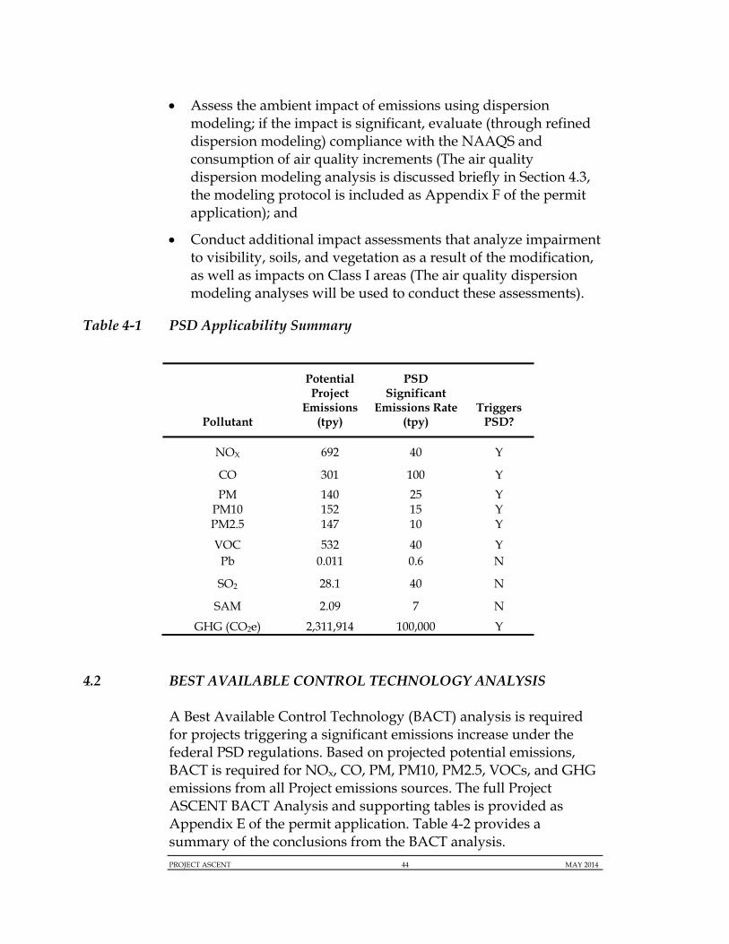
Assess the ambient impact of emissions using dispersion modeling; if the impact is significant, evaluate (through refined dispersion modeling) compliance with the NAAQS and consumption of air quality increments (The air quality dispersion modeling analysis is discussed briefly in Section 4.3, the modeling protocol is included as Appendix F of the permit application); and
Conduct additional impact assessments that analyze impairment to visibility, soils, and vegetation as a result of the modification, as well as impacts on Class I areas (The air quality dispersion modeling analyses will be used to conduct these assessments).
Table 4-1 PSD Applicability Summary
Pollutant
Potential Project
Emissions (tpy)
PSD Significant
Emissions Rate (tpy)
Triggers PSD?
NOX 692 40 Y
CO 301 100 Y
PM PM10 PM2.5
140 152 147
25 15 10
Y Y Y
VOC 532 40 Y Pb 0.011 0.6 N
SO2 28.1 40 N
SAM 2.09 7 N
GHG (CO2e) 2,311,914 100,000 Y
4.2 BEST AVAILABLE CONTROL TECHNOLOGY ANALYSIS
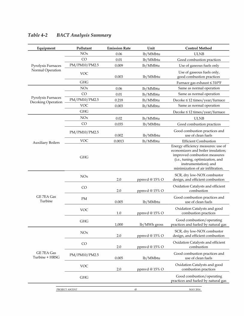
A Best Available Control Technology (BACT) analysis is required for projects triggering a significant emissions increase under the federal PSD regulations. Based on projected potential emissions, BACT is required for NOx, CO, PM, PM10, PM2.5, VOCs, and GHG emissions from all Project emissions sources. The full Project ASCENT BACT Analysis and supporting tables is provided as Appendix E of the permit application. Table 4-2 provides a summary of the conclusions from the BACT analysis.
PROJECT ASCENT 45 MAY 2014
Table 4-2 BACT Analysis Summary
Equipment Pollutant Emission Rate Unit Control Method
Pyrolysis Furnaces Normal Operation
NOx 0.06 lb/MMbtu ULNB CO 0.01 lb/MMbtu Good combustion practices
PM/PM10/PM2.5 0.009 lb/MMbtu Use of gaseous fuels only
VOC 0.003 lb/MMbtu
Use of gaseous fuels only, good combustion practices
GHG Furnace gas exhaust ≤ 310°F
Pyrolysis Furnaces Decoking Operation
NOx 0.06 lb/MMbtu Same as normal operation
CO 0.01 lb/MMbtu Same as normal operation
PM/PM10/PM2.5 0.218 lb/MMbtu Decoke ≤ 12 times/year/furnace VOC 0.003 lb/MMbtu Same as normal operation
GHG Decoke ≤ 12 times/year/furnace
Auxiliary Boilers
NOx 0.02 lb/MMbtu ULNB CO 0.035 lb/MMbtu Good combustion practices
PM/PM10/PM2.5 0.002 lb/MMbtu
Good combustion practices and use of clean fuels
VOC 0.0013 lb/MMbtu Efficient Combustion
GHG
Energy efficiency measures: use of economizers and boiler insulation; improved combustion measures (i.e., tuning, optimization, and
instrumentation); and minimization of air infiltration.
GE 7EA Gas Turbine
NOx 2.0 ppmvd @ 15% O
SCR, dry low-NOX combustor design, and efficient combustion
CO 2.0 ppmvd @ 15% O
Oxidation Catalysts and efficient combustion
PM 0.005 lb/MMbtu
Good combustion practices and use of clean fuels
VOC 1.0 ppmvd @ 15% O
Oxidation Catalysts and good combustion practices
GHG 1,000 lb/MWh gross
Good combustion/operating practices and fueled by natural gas
GE 7EA Gas Turbine + HRSG
NOx 2.0 ppmvd @ 15% O
SCR, dry low-NOX combustor design, and efficient combustion
CO 2.0 ppmvd @ 15% O
Oxidation Catalysts and efficient combustion
PM/PM10/PM2.5 0.005 lb/MMbtu
Good combustion practices and use of clean fuels
VOC 2.0 ppmvd @ 15% O
Oxidation Catalysts and good combustion practices
GHG
Good combustion/operating practices and fueled by natural gas
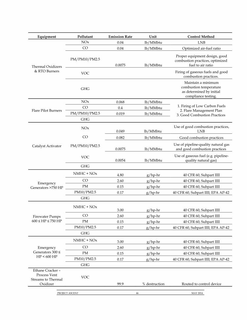
PROJECT ASCENT 46 MAY 2014
Equipment Pollutant Emission Rate Unit Control Method
Thermal Oxidizers & RTO Burners
NOx 0.04 lb/MMbtu LNB CO 0.04 lb/MMbtu Optimized air-fuel ratio
PM/PM10/PM2.5
0.0075 lb/MMbtu
Proper equipment design, good combustion practices, optimized
fuel to air ratio
VOC
Firing of gaseous fuels and good combustion practices.
GHG
Maintain a minimum combustion temperature as determined by initial
compliance testing.
Flare Pilot Burners
NOx 0.068 lb/MMbtu 1. Firing of Low Carbon Fuels
2. Flare Management Plan 3. Good Combustion Practices
CO 0.4 lb/MMbtu PM/PM10/PM2.5 0.019 lb/MMbtu
GHG
Catalyst Activator
NOx 0.049 lb/MMbtu
Use of good combustion practices, LNB
CO 0.082 lb/MMbtu Good combustion practices
PM/PM10/PM2.5 0.0075 lb/MMbtu
Use of pipeline-quality natural gas and good combustion practices
VOC 0.0054 lb/MMbtu
Use of gaseous fuel (e.g. pipeline-quality natural gas)
GHG
Emergency Generators >750 HP
NMHC + NOx 4.80 g/hp-hr 40 CFR 60, Subpart IIII CO 2.60 g/hp-hr 40 CFR 60, Subpart IIII PM 0.15 g/hp-hr 40 CFR 60, Subpart IIII
PM10/PM2.5 0.17 g/hp-hr 40 CFR 60, Subpart IIII; EPA AP-42
GHG
Firewater Pumps 600 ≤ HP ≤ 750 HP
NMHC + NOx 3.00 g/hp-hr 40 CFR 60, Subpart IIII
CO 2.60 g/hp-hr 40 CFR 60, Subpart IIII PM 0.15 g/hp-hr 40 CFR 60, Subpart IIII
PM10/PM2.5 0.17 g/hp-hr 40 CFR 60, Subpart IIII; EPA AP-42
GHG
Emergency Generators 300 ≤
HP < 600 HP
NMHC + NOx 3.00 g/hp-hr 40 CFR 60, Subpart IIII CO 2.60 g/hp-hr 40 CFR 60, Subpart IIII PM 0.15 g/hp-hr 40 CFR 60, Subpart IIII
PM10/PM2.5 0.17 g/hp-hr 40 CFR 60, Subpart IIII; EPA AP-42
GHG Ethane Cracker –
Process Vent Streams to Thermal
Oxidizer
VOC
99.9 % destruction Routed to control device

PROJECT ASCENT 47 MAY 2014
Equipment Pollutant Emission Rate Unit Control Method PE Plant Process Vent Streams to
Flares VOC
98.0 % destruction Routed to control device LPDE Plant Process
Vent Streams to RTO
VOC 99.0 % destruction Routed to control device
Cooling Tower PM 0.0005 % Drift High-efficiency drift eliminators
VOC Use of Leak Detection and Repair Program
Tanks VOC Subpart Kb as applicable
Material Handling PM 0.01 gr/scf @ exhaust
Dust collectors as needed and best management practices
Loading/Unloading Operations
VOC Collection System and 98% destruction treatment for handling of streams with vapor pressure > 0.5 psia for loading/unloading operations
Fugitive Leaks VOC LDAR for VOC services (NSPS VVa)
GHG LDAR and AVO inspections for GHG sources not in VOC service
4.3 NAAQS DISPERSION MODELING ANALYSIS
The PSD regulations require additional analyses beyond BACT assessments including:
An assessment of compliance with NAAQS and PSD increments;
An evaluation of whether the Project results in any impairment to visibility, soils, and vegetation that would occur as a result of the new source, and of general commercial, residential, industrial, and other growth associated with the new source. Furthermore, impacts on Class I areas must be analyzed to determine compliance with Class I increments and to assess the impacts of new emissions on air quality related values (AQRVs); and
An evaluation of the Project’s impacts on PSD Class I Areas.
The most current version of the Project Ascent Air Quality Modeling Protocol is included as Appendix F of the permit application. Upon approval of the protocol by WVDEP, ASCENT will complete the analyses above including the NAAQS and PSD increment compliance demonstrations. The modeling analyses will be submitted to WVDEP under separate cover.
PROJECT ASCENT 48 MAY 2014
5.0 NON-ATTAINMENT NEW SOURCE REVIEW (NA-NSR)
The Parkersburg-Marietta, WV-OH area, which includes Wood County and the Grant Tax District in Pleasants County, is in attainment for all criteria pollutants. As there are no areas in Wood County with the air quality designated as non-attainment, a non-attainment new source review is not required for this Project.
PROJECT ASCENT 49 MAY 2014
6.0 APPLICABLE REQUIREMENTS REVIEW
This section briefly outlines the significant federal and State air quality requirements to which the proposed ASCENT Project will be subject, in addition to the PSD and NA-NSR requirements presented previously.
6.1 FEDERAL REQUIREMENTS
6.1.1 New Source Performance Standards (NSPS)
6.1.1.1 Steam Generating Units (Subpart Db)
The natural gas fired auxiliary boilers are subject to 40 CFR 60, Subpart Db, “Standards of Performance for Industrial-Commercial-Institutional Steam Generating Units.” The affected facility includes all steam generating units constructed, modified, or reconstructed after June 19, 1984 and that have a heat input capacity greater than 29 megawatts (MW) (100 MMBtu/hr). Note that affected facilities regulated under Subpart Db are exempt from the requirements of Subpart D.
The Subpart Db emission limits are:
SO2
o 0.20 lb/MMBtu; or
o 92 percent reduction of the potential SO2 emission rate and 1.2 lb/MMBtu;
PM – Does not apply to natural gas-fired units;
NOx
o Low heat release rate (70,000 Btu/hr-ft3 or less) – 0.10 lb/MMBtu; and
o High heat release rate (greater than 70,000 Btu/hr-ft3) – 0.20 lb/MMBtu.

PROJECT ASCENT 50 MAY 2014
Subpart Db includes general compliance requirements (60.45b & 40.56b), emissions monitoring requirements (60.47b & 60.48b), and reporting requirements (60.49b). The ASCENT Project will also be subject to applicable notification, monitoring and reporting and related applicable provisions of 40 CFR 60.7 and 60.8.
6.1.1.2 Volatile Organic Liquid Storage Vessels (Subpart Kb)
The affected facility subject to 40 CFR 60 Subpart Kb, “Standards of Performance for Volatile Organic Liquid Storage Vessels (Including Petroleum Liquid Storage Vessels) For Which Construction, Reconstruction, or Modification Commenced After July 23, 1984” is storage vessels containing volatile organic liquids with a capacity greater than or equal to 75 m3. This subpart does not apply to storage vessels with a capacity greater than or equal to 151 m3 storing a liquid with a maximum true vapor pressure less than 3.5 kilopascals (kPa), or storage vessels with a capacity greater than or equal to 75 m3, but less than 151 m3 storing a liquid with a maximum true vapor pressure less than 15.0 kPa. All subject storage tanks are required to be equipped with a fixed roof in combination with an internal floating roof, an external floating roof, or a closed vent system and control device. The storage tanks for the ASCENT Project will use a closed vent system and control device to meet the requirements of 40 CFR 63, Subpart Kb. The facility will be subject to the monitoring, testing, recordkeeping, and reporting requirements in 60.113b-116b.
6.1.1.3 Polymer Manufacturing Industry (Subpart DDD)
The affected facilities that are subject to 40 CFR 60, Subpart DDD, “Standards of Performance for VOC Emissions from the Polymer Manufacturing Industry” are polyethylene equipment, from raw material preparation to product storage, which are constructed, modified, or reconstructed after January 10, 1989. Note that affected facilities regulated under Subpart DDD are exempt from the requirements of 40 CFR 60, Subpart III, NNN, and RRR.
Subpart DDD includes emissions standards for affected polyethylene manufacturing facilities in 60.562-1(a). Continuous standard process emission streams will be controlled in accordance with 60.562-1(a)(1)(i)(D) by venting to a control device located on the Project site. Intermittent emissions will be controlled in
PROJECT ASCENT 51 MAY 2014
accordance with 60.562-2(i)A-C by combusting the emissions in a flare designed to maintain a stable flame, operate with a flame at all times, and operate with no visible emissions, except for periods not to exceed a total of 5 minutes during any 2 consecutive hours.
Subpart DDD affected facilities are subject to the rules set forth in 40 CFR 60, Subpart VVa, “Standards of Performance for Equipment Leaks of VOC in the Synthetic Organic Chemicals Manufacturing Industry for Which Construction, Reconstruction, or Modification Commenced After November 7, 2006”. Polyethylene manufacturing plants are required to implement a Leak Detection and Repair (LDAR) program that complies with the equipment leaks of VOC requirement set forth in Subpart VVa (60.482-1-60.482-10).
Subpart DDD also includes monitoring (60.563), testing (60.564), and reporting and recordkeeping (60.565) requirements.
6.1.1.4 Commercial and Industrial Solid Waste Incinerator (Subpart CCCC)
An emission source is subject to the proposed CISWI Rule if it would combust solid or liquid materials defined to be commercial or industrial solid waste under the proposed EPA Solid Waste Identification Rule. There is no de minimis threshold for applicability based on a minimum facility size or processing rate. However, under the proposed Solid Waste Identification Rule, if a material is determined not to be a solid waste material, it is then classified as being either a “fuel” or a process “ingredient” when combusted. For such non-waste “fuels” or “ingredients,” combustion of the material would not be regulated under the CISWI Rule.
Project ASCENT will not be subject to the CISWI rule. ASCENT is coordinating with the design technology vendors to ensure that streams to control equipment (e.g., thermal oxidizers) meet the requirements for non-regulated materials.
6.1.1.5 Compression Ignition Internal Combustion Engines (Subpart IIII)
The emergency generators and fire water pumps are subject to 40 CFR 60, Subpart IIII, “Standards of Performance for Stationary Compression Ignition Internal Combustion Engines” and the associated fuel, monitoring, compliance, testing, notification,
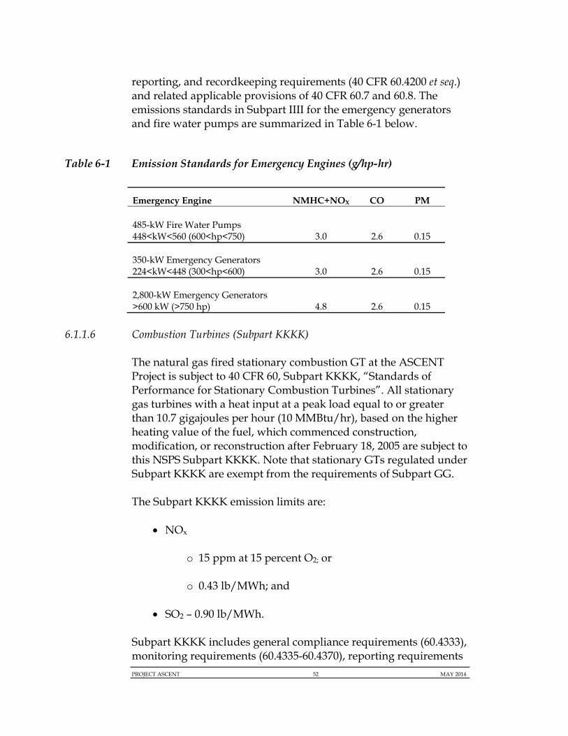
PROJECT ASCENT 52 MAY 2014
reporting, and recordkeeping requirements (40 CFR 60.4200 et seq.) and related applicable provisions of 40 CFR 60.7 and 60.8. The emissions standards in Subpart IIII for the emergency generators and fire water pumps are summarized in Table 6-1 below.
Table 6-1 Emission Standards for Emergency Engines (g/hp-hr)
Emergency Engine NMHC+NOX CO PM
485-kW Fire Water Pumps 448<kW<560 (600<hp<750) 3.0 2.6 0.15
350-kW Emergency Generators 224<kW<448 (300<hp<600) 3.0 2.6 0.15
2,800-kW Emergency Generators >600 kW (>750 hp) 4.8 2.6 0.15
6.1.1.6 Combustion Turbines (Subpart KKKK)
The natural gas fired stationary combustion GT at the ASCENT Project is subject to 40 CFR 60, Subpart KKKK, “Standards of Performance for Stationary Combustion Turbines”. All stationary gas turbines with a heat input at a peak load equal to or greater than 10.7 gigajoules per hour (10 MMBtu/hr), based on the higher heating value of the fuel, which commenced construction, modification, or reconstruction after February 18, 2005 are subject to this NSPS Subpart KKKK. Note that stationary GTs regulated under Subpart KKKK are exempt from the requirements of Subpart GG.
The Subpart KKKK emission limits are:
NOx
o 15 ppm at 15 percent O2; or
o 0.43 lb/MWh; and
SO2 – 0.90 lb/MWh.
Subpart KKKK includes general compliance requirements (60.4333), monitoring requirements (60.4335-60.4370), reporting requirements

PROJECT ASCENT 53 MAY 2014
(60.4375-60.4395), and performance testing (60.4400-60.4415). The affected facilities will also be subject to applicable notification, monitoring and reporting and related applicable provisions of 40 CFR 60.7 and 60.8.
6.1.1.7 NSPS for GHGs
On September 20, 2013, USEPA proposed a revised Carbon Pollution Standard that would set national limits on the amount of GHGs emissions allowed for new power plants. The rule will be promulgated under authority of Section 111 of the Clean Air Act (i.e., NSPS), and applies to new electric utility generating units (EGUs).
USEPA is proposing to codify the CO2 standards of performance in the same subparts – Da and KKKK, depending on the types of units – that currently include the standards of performance for conventional pollutants. However, USEPA is co-proposing an alternative to codify the CO2 standards in a new Subpart, TTTT, as in USEPA’s original April 2012 proposal.
This new proposal was issued after USEPA received and reviewed more than 2.5 million public comments on the April 2012 Carbon Pollution Standard. Concurrent with this proposal, USEPA is rescinding the original April 2012 proposed rule.
In a change from the April 2012 proposal, USEPA is now proposing a standard of performance for natural gas-fired stationary combustion turbines and for fossil fuel-fired utility boilers and integrated gasification combined-cycle (IGCC) units called the Best System of Emission Reduction (BSER). This is the most controversial part of the rule.
For affected gas turbine EGUs, the proposed limits are based on the performance of a combined-cycle design with two (1) size categories. Larger units with a heat input rating greater than 850 MMBtu/hr will be required to meet a standard of 1,000 pounds of CO2 per gross megawatt-hour (lb-CO2/MWh gross). Units rated less than 850 MMBtu/hr will be subject to a standard of 1,100 lb-CO2/MWh gross. USEPA states that it considers modern and efficient natural-gas combined-cycle (NGCC) as BSER for new affected combustion turbines (Subpart KKKK sources). USEPA

PROJECT ASCENT 54 MAY 2014
decided that CCS could not be considered as BSER for gas-fired GTs due to: 1) the significantly lower concentration of CO2 in the flue gas; 2) there is only one (1) CCS demonstration project on a NGCC facility; and 3) the potential of significant impacts to electricity prices and reliability of the imposition of CCS on few coal fired units.
This rulemaking will continue to be monitored and, upon its promulgation, will be evaluated to determine applicability to the Project.
6.1.2 National Emission Standard for Hazardous Air Pollutants (NESHAP)
National Emissions Standards for Hazardous Air Pollutants (NESHAPs) are federal HAP requirements in 40 CFR 63 that apply generally to "major" sources of HAPs, defined as facilities with the potential to emit 10 tpy or more of any single HAP or 25 tpy or more of all HAPs. HAP standards, known as Maximum Achievable Control Technology (MACT) standards, for major HAP sources are established for classes or categories of sources.
The total potential HAP emissions for the facility are projected to be more than 25 tpy for all HAPs combined. Therefore, the Project is considered a major HAP source and source-specific MACT standards apply.
6.1.2.1 Industrial Process Cooling Towers (Subpart Q)
The quench tower for the ASCENT Project is not subject to 40 CFR 63, Subpart Q, “National Emission Standards for Hazardous Air Pollutants for Industrial Process Cooling Towers”, since it is not operated with chromium-based water treatment chemicals.
6.1.2.2 Equipment Leaks – Control Level 2 Standards (Subpart UU)
The provisions of 40 CFR 63, Subpart UU, “National Emission Standard for Equipment Leaks – Control Level 2 Standards”, apply to the control of air emissions from equipment leaks for which another subpart references the use of this subpart for such air emission control. The equipment leaks associated with the Project are subject to Subpart UU as referenced by 63.1103(e) (Subpart YY).
PROJECT ASCENT 55 MAY 2014
Equipment that contains or contacts regulated HAPs, including pumps, compressors, agitators, pressure relief devices, sampling connection systems, open-ended valves or lines, valves, connectors, instrumentation systems, closed vent systems, and control devices is subject. Subject equipment will be identified and monitored using an instrument reading that defines a leak based upon the standards of the component outlined in 63.1025-1034. The facility will also be subject to the recordkeeping and reporting requirements of 63.1038-1039 for applicable components.
6.1.2.3 Ethylene Manufacturing Process Units: Heat Exchange Systems and Waste Operation (Subpart XX)
A heat exchange system is subject to 40 CFR 63, Subpart XX, “National Emission Standards for Ethylene Manufacturing Process Units: Heat Exchange Systems and Waste Operations” if regulations for ethylene production units in Subpart YY require a facility to comply with Subpart XX. Heat exchange systems at the site are subject to the MACT standards outlined in Subpart YY of general monitoring, recordkeeping, and the reporting requirements of 40 CFR 63.1084-63.1090. Project ASCENT does not include any heat exchange systems operated within the polyethylene units that are subject to this regulation.
Waste operations that have waste streams containing butadiene or benzene at the facility are subject to this subpart. Continuous butadiene waste streams that contain greater than or equal to 10 ppmw 1,3-butadiene and have a flow rate greater than or equal to 0.02 liter per minute have the following applicable MACT standards:
The continuous butadiene stream must be routed to a treatment process or wastewater treatment system that complies with 40 CFR 61.348;
Receiving waste management units must comply with applicable MACT standards;
Recordkeeping requirements of 40 CFR 61.356b; and Reporting requirements of 40 CFR 61.357a.
Waste streams that contain benzene must be either treated at the facility according to 40 CFR 61.342(c)(1)-(3) or transported off site in
PROJECT ASCENT 56 MAY 2014
accordance with 40 CFR 63.1096. There will not be any waste streams that contain benzene within the polyethylene units for the Project.
6.1.2.4 Generic MACT Standards (Subpart YY)
The ASCENT Project is subject to 40 CFR 63, Subpart YY “National Emissions Standards for Hazardous Air Pollutants for Source Categories: Generic Maximum Achievable Control Technology Standards” as ethylene production is a source categories listed in 63.1110. The applicable MACT standards for ethylene process vents, transfer racks, equipment containing or contacting HAPs, processes that generate waste, and heat exchange systems are as follows:
Ethylene process vents – Reduce HAP emissions by 98% or to a TOC concentration of 20 ppmv;
Transfer racks – Reduce HAP emissions by 98% or to a TOC concentration of 20 ppmv or install process piping to capture HAP-containing vapors during loading activities;
Equipment containing or contacting HAPs – Comply with 40 CFR 63, Subpart UU;
Processes that generate waste – Comply with 40 CFR 63, Subpart XX; and
Heat exchange systems – Comply with 40 CFR 63, Subpart XX.
6.1.2.5 Stationary Combustion Turbines (Subpart YYYY)
The affected units subject to 40 CFR 63, Subpart YYYY, “National Emission Standards for Hazardous Air Pollutants for Stationary Combustion Turbines”, are stationary CTs located a major source of HAP emissions that are constructed or reconstructed after January 14, 2003. The ASCENT Project equipment is subject to the provisions of this subpart including a 91 ppbv or less at 15 percent oxygen formaldehyde emission limit for the gas-fired CT.
PROJECT ASCENT 57 MAY 2014
6.1.2.6 Stationary Reciprocating Internal Combustion Engines (Subpart ZZZZ)
All of the emergency generators and fire water pumps are subject to 40 CFR 63, Subpart ZZZZ “National Emissions Standards for Hazardous Air Pollutants for Stationary Reciprocating Internal Combustion Engines” and its associated fuel, monitoring, compliance, testing, notification, reporting, and recordkeeping requirements. However as per 63.6590(c)(7), the 350 kW emergency generators (SU-EG-108 & SU-EG-109) are required to meet the requirements of this subpart by complying for the requirements of 40 CFR 60, Subpart IIII as they are new emergency stationary RICE rated at less than 500 hp that are located at a major source of HAP emissions. In addition, the emergency equipment rated at greater than 500 hp is subject to limited requirements as per 63.6590(b)(1)(i). These limited requirements include monitoring requirements in 63.6605(b) and 63.6640(f) and notification requirements in 63.6645(f).
6.1.2.7 Major Sources: Industrial, Commercial, and Institutional Boilers and Process Heaters (Subpart DDDDD)
Since the Project will be a major source of HAPs, the auxiliary boilers are subject to 40 CFR 63, Subpart DDDDD, “National Emission Standards for Hazardous Air Pollutants for Major Sources: Industrial, Commercial, And Institutional Boilers and Process Heaters”. This subpart applies to new or reconstructed industrial, commercial, and institutional boilers and process heaters where construction commenced after June 4, 2010. There are no emission limits in this regulation for new or reconstructed natural gas-fired boilers or process heaters; however, emission limitations are regulated under 40 CFR 60 Subpart Db, “Standards of Performance for Industrial-Commercial-Institutional Steam Generating Units” (See Section 6.1.1.1). The auxiliary boilers are subject to the testing, analysis, initial compliance, notification, reporting, and recordkeeping requirements 63.7505-63.7575.
6.1.3 Acid Rain Program
The proposed combustion turbine meets the definition of an “affected unit” as defined in 40 CFR 72.6, and are therefore subject to the requirements of the Acid Rain Program, including emissions standards (40 CFR 72.9) and monitoring requirements (40 Part 75), among other requirements. In addition, the Project owner is

PROJECT ASCENT 58 MAY 2014
required to apply for, and obtain, an Acid Rain permit, pursuant to 40 CFR 72.30. The terms of the Acid Rain permit will be incorporated into the facility’s Title V operating permit when it is issued by WVDEP in the future. Pursuant to 40 CFR 72.30(b)(2)(ii), the Acid Rain permit application must be submitted to the permitting authority at least 24 months before the date on which a unit commences operation. With commencement of operation expected in the second quarter of 2018, the Acid Rain permit application must be submitted by the second quarter of 2016.
6.2 STATE REQUIREMENTS
The proposed Project will be subject to a number of WVDEP air quality requirements including, but not limited to, the following:
6.2.1 To Prevent and Control Particulate Air Pollution from Combustion of Fuel in Indirect Heat Exchangers (45 CSR 02)
The auxiliary boilers are natural gas-fired indirect heat exchangers with design heat input capacities greater than 10 MMBtu/hr. The auxiliary boilers will comply with the applicable particulate matter emission limits and visible emission standards in the rule.
6.2.2 To Prevent and Control the Discharge of Air Pollutants into Open Air which Causes or Contributes to an Objectionable Odor or Odors (45 CSR 04)
Materials used and manufactured do not have low odor thresholds. Emissions from the facility will be controlled by various air pollution control devices that should further minimize potential objectionable odors.
6.2.3 To Prevent and Control Air Pollution from Combustion of Reuse (45 CSR 06)
Thermal oxidizers and flares are designed and operated to comply with the allowable particulate matter and opacity limitations.
PROJECT ASCENT 59 MAY 2014
6.2.4 To Prevent and Control Particulate Matter Air Pollution from Manufacturing Processes and Associated Operations (45 CSR 07)
Particulate matter emissions from manufacturing processes, associated operations, and fugitive sources will be designed and controlled to comply with the allowable particular matter emissions limitations, opacity standards, and minimization of fugitive emissions.
6.2.5 To Prevent and Control Air Pollution from the Emission of Sulfur Oxides (45 CSR 10)
The auxiliary boilers are natural gas-fired indirect heat exchangers with a design heat input capacity greater than 10 MMBtu/hr and the pyrolysis furnaces are fuel burning units having a design input of greater than 10 MMBtu/hr. These units will comply with the applicable sulfur dioxide emission limits in the rule.
6.2.6 Prevention of Air Pollution Emergency Episodes (45 CSR 11)
When requested by the WVDEP Director, standby plans for reducing air pollutant emissions during Air Pollution Alerts, Air Pollution Warnings, and Air Pollution Emergencies will be prepared.
6.2.7 Permits for Construction, Modification, Relocation and Operation of Stationary Sources of Air Pollutants, Notification Requirements, Administrative Updates, Temporary Permits, General Permits, Permission to Commence Construction, and Procedures for Evaluation (45 CSR 13)
This permit application is being submitted pursuant to 45 CSR 13 for the construction of the proposed Project.
6.2.8 Permits for Construction and Major Modification of Major Stationary Sources of Air Pollution for the Prevention of Significant Deterioration (45 CSR 14)
As described in Section 4.1, the proposed Project will be subject to PSD for NOx, CO, PM, PM10, PM2.5, VOC, and GHGs.
PROJECT ASCENT 60 MAY 2014
6.2.9 Standards of Performance for New Stationary Sources (45 CSR 16)
As further detailed in Section 6.1.1, the proposed Project is subject to NSPS Subparts Db, Kb, DDD, IIII, and KKKK.
6.2.10 Permits for Construction and Major Modification of Major Stationary Sources of Air Pollution Which Cause or Contribute to Non-Attainment (45 CSR 19)
The proposed Project is not located in a designated Non-Attainment area and will not trigger non-attainment NSR.
6.2.11 Good Engineering Practice as Applicable to Stack Heights (45 CSR 20)
Stack heights are designed to comply with good engineering practices specified by this regulation.
6.2.12 Regulation to Prevent and Control Air Pollution from the Emissions of VOCs (45 CSR 21)
The proposed Project will be located in Wood County, West Virginia, which is one of the counties subject to this regulation. Source specific sections potentially applicable to this project include §45-21-37 (Leaks from Synthetic Organic Chemical, Polymer, and Resin Manufacturing Equipment), §45-21-38 (Manufacture of High-Density Polyethylene, Polypropylene, and Polystyrene Resins), and §45-21-40 (Other Facilities that Emit Volatile Organic Compound (VOC). The Project will comply with these sections’ requirements, as well as other applicable testing and continuous emissions sections, by complying with the NSPS and NESHAP requirements as outlined in Sections 6.1.1 and 6.1.2, respectively.
6.2.13 To Prevent and Control the Emissions of Toxic Air Pollutants (45 CSR 27)
Regulated Toxic Air Pollutants (TAP) are also defined as Hazardous Air Pollutants (HAP). Air pollutant controls are installed and operated to meet the National Emission Standards for Hazardous Air Pollutants will also comply with this Rule’s applicable requirements.

PROJECT ASCENT 61 MAY 2014
6.2.14 Requirements for Operating Permits (45 CSR 30)
The proposed Project will require a Title V Operating Permit. Pursuant to 45 CSR 30-4.1.a.2., the Project owners must file a complete application to obtain the Title V operating permit within 12 months after the Project commences operation, which is expected to occur in 2018.
6.2.15 Acid Rain Provisions and Permits (45 CSR 33)
The proposed GT will be subject to certain provisions of the acid Rain program, including the permitting provisions.
6.2.16 Emission Standards for Hazardous Air Pollutants (45 CSR 34)
As further detailed in Section 6.1.2, the proposed Project is subject to NESHAP Q, UU, XX, YY, YYYY, ZZZZ, and DDDDD.

PROJECT ASCENT 62 MAY 2014
7.0 CONCLUSIONS
Emissions from the proposed Project trigger PSD requirements for NOx, CO, PM, PM10, PM2.5, VOC, and GHG. No pollutants trigger NA-NSR. Emissions of all other regulated pollutants, including HAPs, will be below regulatory thresholds.
Because emissions of NOx, CO, PM, PM10, PM2.5, VOC, and GHG trigger PSD, Project ASCENT is required to meet BACT for these pollutants, and conduct impact assessments to ensure that emissions will not adversely affect ambient air quality.
Emissions from the proposed Project are not predicted to cause any significant adverse impacts to air quality. Specifically, emissions from the proposed Project will not adversely affect ambient air quality or PSD increments. The Project’s impacts on visibility in the surrounding Class I areas are likely to be minimal.
In conclusion, an evaluation of the Project and its potential emissions indicates that Project ASCENT will meet all applicable State and federal air quality requirements.