Appendix 8: Timber Frame · PDF fileAppendix 8: Timber Frame Detailing This appendix...
15
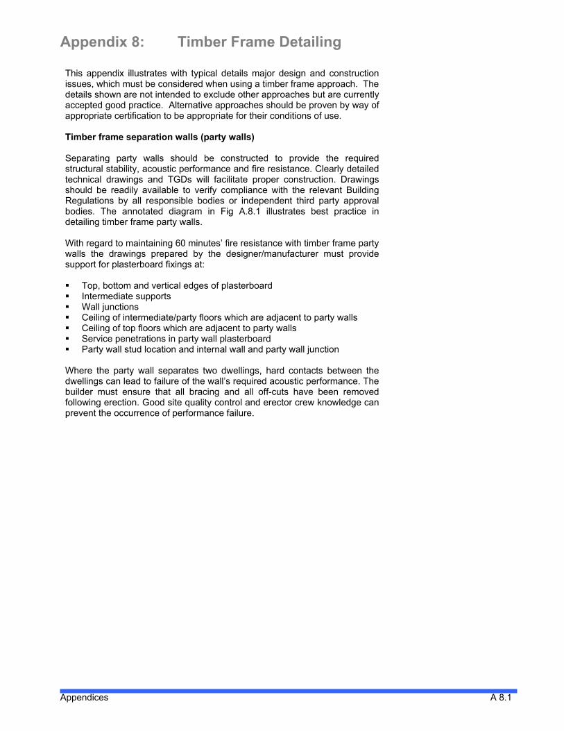
Appendix 8: Timber Frame Detailing This appendix illustrates with typical details major design and construction issues, which must be considered when using a timber frame approach. The details shown are not intended to exclude other approaches but are currently accepted good practice. Alternative approaches should be proven by way of appropriate certification to be appropriate for their conditions of use. Timber frame separation walls (party walls) Separating party walls should be constructed to provide the required structural stability, acoustic performance and fire resistance. Clearly detailed technical drawings and TGDs will facilitate proper construction. Drawings should be readily available to verify compliance with the relevant Building Regulations by all responsible bodies or independent third party approval bodies. The annotated diagram in Fig A.8.1 illustrates best practice in detailing timber frame party walls. With regard to maintaining 60 minutes’ fire resistance with timber frame party walls the drawings prepared by the designer/manufacturer must provide support for plasterboard fixings at: Top, bottom and vertical edges of plasterboard Intermediate supports Wall junctions Ceiling of intermediate/party floors which are adjacent to party walls Ceiling of top floors which are adjacent to party walls Service penetrations in party wall plasterboard Party wall stud location and internal wall and party wall junction Where the party wall separates two dwellings, hard contacts between the dwellings can lead to failure of the wall’s required acoustic performance. The builder must ensure that all bracing and all off-cuts have been removed following erection. Good site quality control and erector crew knowledge can prevent the occurrence of performance failure. Appendices A 8.1
Transcript of Appendix 8: Timber Frame · PDF fileAppendix 8: Timber Frame Detailing This appendix...
Appendix 8: Timber Frame Detailing
This appendix illustrates with typical details major design and construction issues, which must be considered when using a timber frame approach. The details shown are not intended to exclude other approaches but are currently accepted good practice. Alternative approaches should be proven by way of appropriate certification to be appropriate for their conditions of use.
Timber frame separation walls (party walls) Separating party walls should be constructed to provide the required structural stability, acoustic performance and fire resistance. Clearly detailed technical drawings and TGDs will facilitate proper construction. Drawings should be readily available to verify compliance with the relevant Building Regulations by all responsible bodies or independent third party approval bodies. The annotated diagram in Fig A.8.1 illustrates best practice in detailing timber frame party walls. With regard to maintaining 60 minutes’ fire resistance with timber frame party walls the drawings prepared by the designer/manufacturer must provide support for plasterboard fixings at: Top, bottom and vertical edges of plasterboard Intermediate supports Wall junctions Ceiling of intermediate/party floors which are adjacent to party walls Ceiling of top floors which are adjacent to party walls Service penetrations in party wall plasterboard Party wall stud location and internal wall and party wall junction
Where the party wall separates two dwellings, hard contacts between the dwellings can lead to failure of the wall’s required acoustic performance. The builder must ensure that all bracing and all off-cuts have been removed following erection. Good site quality control and erector crew knowledge can prevent the occurrence of performance failure.
Appendices A 8.1

Figure A.8.1 Typical 60-minute 2 storey separating wall with attic space illustrating current good practice in timber frame construction.
SECTION DETAIL (not to scale)
Appendices A8.2

Services Installations at Timber Frame Party Wall Construction Installing services within a party wall is not permitted in Scotland. This is overcome by installing the services between the party wall and an internal ‘dummy’ wall. While this may satisfy concerns regarding fire resistance, it does not address occupier perceptions. The ‘dummy’ wall may give the occupier a sense that the walls are not robust and issues may arise with regard to hanging shelves or heavy furnishings such as mirrors.
Figure A.8.2 An alternative battened out services void can be used where services cannot be avoided at party walls. The services are installed in the void and the party wall proper is left with no penetrations or services.
PLAN DETAIL (not to scale)
Services are not permitted in timber frame separating (party wall) walls in Ireland. Services must therefore be carefully thought out and should avoid the party wall. If this is impossible an alternative is to construct a services void in adding to the party wall construction (see figure A.8.2).
Appendices A8.3

60-Minute Party Wall Junction with Load-Bearing External Wall Adequate timber support for plasterboard fixings is essential when providing 60 minutes, fire resistance between dwellings and required fire resistance to load-bearing walls. The doubling up of studs and the use of 140 mm L-type corners is recommended by the Consortium. L-type corners also provide the insulation installers with open access to junctions and/or corners, which helps minimise sound transfer and cold bridging.
Figure A.8.3 Typical timber frame 60-minute separating wall junction with timber frame external wall and masonry cladding.
PLAN DETAIL (not to scale)
Appendices A8.4

Party Wall with Trusses Running Perpendicular to Party Wall To ensure 60 minutes, fire resistance between dwellings when trusses run 90 degree to party walls, the Consortium recommends that truss ends be supported by a girder, not the party wall. This girder truss may have multiple pitches and/or a flat top section but will ensure that the plasterboard is not penetrated (see figure A.8.4)
Figure A.8.4 Typical detail of a 60-minute separating wall where perpendicular to timber roof trusses.
SECTION DETAIL (not to scale)
Appendices A8.5

Appendices A8.6
Chimneys Adjacent to Party Walls To ensure 60 minutes, fire resistance and compliance with acoustic requirements between dwellings where chimneys are bordering on party walls, acoustic insulation and plasterboard can be installed at party walls adjacent to the chimney before the installation of the chimney. This is not that dissimilar to stairwell/staircase and spandrel panel details. Double trimmer joists should be installed to support party walls and to provide 60 minutes, fire resistance at floor zones. On using this detail, the chimney will not penetrate the plasterboard and will be located approximately 184 mm from the centre of the party wall cavity (see figures A.8.5 and A.8.6). The installation of the plasterboard and all fire stopping and insulation must be confirmed prior to installation of the fireplace and flue construction. This is an important site quality control issue.
Figure A.8.5 Fireplace installation allowing continuous party wall construction can be used as an alternative to a back to back fireplace installation. Note that this will take more space within the room.
PLAN DETAIL (not to scale)
Figure A.8.6 Flue installation allowing continuous party wall construction can be used as an alternative to a back to back fireplace installation. Note that this will take more space within the room.
PLAN DETAIL (not to scale)

Open Deck Balcony Details Prevention of moisture ingress into structural timbers is paramount in open deck balcony detailing. Lead work guarantees moisture protection and is recommended by the Consortium when detailing an open deck balcony. Cantilevered joists must be dropped below final floor level and lead work must return under all door openings to prevent moisture ingress. Detailing of breather membrane and lead work junction is as typical but care must be taken not to restrict ventilation to timber and/or external wall cavity; drainage of external wall cavity must also be maintained (see Figure A.8.7). The durability of this type of detail is suspect due to its complexity and potential for failure.
Figure A.8.7 Typical open deck timber frame balcony detail.
SECTION DETAIL (not to scale)
Appendices A8.7

Closed Deck Balcony Prevention of moisture ingress into structural timbers is paramount in closed deck balcony detailing. An appropriate roof covering guarantees moisture protection and the use of duckboards will offer a durable deck surface. The Consortium recommends both. Cantilevered joists must be dropped below final floor level and roof covering must return under all door openings to prevent moisture ingress. Detailing of breather membrane and floor covering junction is as typical but care must be taken not to restrict ventilation to timber and/or external wall cavity; drainage of external wall cavity must also be maintained (see figure A.8.8)
Figure A.8.8 Typical closed deck timber frame balcony detail.
SECTION DETAIL (not to scale)
Appendices A8.8

Balcony at Penthouse Wall Section Load transfer and tie down of penthouses can be equated to roof design and will require structural load transfer from the top down. Penthouse load- bearing walls may need to be designed as truss walls if load transfer is localised. Detailing of breather membrane and roof covering junction is as typical but care must be taken not to restrict ventilation to timber and/or external wall cavity; drainage of external wall cavity must also be maintained (see Fig A.8.9).
Figure A.8.9 Typical closed deck timber frame balcony detail at a penthouse level. The finish deck material may vary and should be installed in accordance with the manufacturer’s requirements and the requirements of the roofing manufacturer.
SECTION DETAIL (not to scale)
Appendices A8.9

Differential Movement in Mid-Rise construction Timber responds to changes in humidity by expanding or contracting across its grain. A 38 mm thick timber sole plate can expand by 1 mm, a 241 mm solid timber joist by 6 mm. The key to reducing differential movement is to design out the horizontal cross grain and use manufactured timber products that do not have a grain running in one direction. Sole plates, solid timber joists, solid timber lintels, top and bottom rails are all typical examples of horizontal cross grain timber in a structure. Differential movement of a structure can be calculated by measuring the total thickness of horizontal cross grain timber used in the full height of the building. By reducing this to a minimum and by using manufactured timber products in locations where differential movement is greatest, differential movement can be reduced to manageable levels – even at 6 storeys. Differential movement occurs as a consequence of cross grain shrinkage of the timber. The biggest proportion of cross grain shrinkage will occur in the floor joists. The shrinkage in the rails and binders does not normally affect internal linings or sheathing to the panels. However, plasterboard lining to staircase openings of two or more storeys can be affected as the floor joist zone is crossed. The risk of cracking as a result of shrinkage can be overcome by incorporating a movement gap in the plasterboard with a cover strip at the floor zone. Differential movement may be countered by adopting a number of approaches such as: Reducing the amount of cross grain timber in wall panels by hanging
joists off joist hangers Specifying super dry joists Specifying engineered wood products
Appendices A8.10
Appendices A8.11
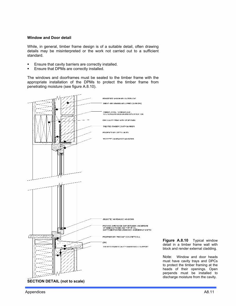
Window and Door detail While, in general, timber frame design is of a suitable detail, often drawing details may be misinterpreted or the work not carried out to a sufficient standard. Ensure that cavity barriers are correctly installed. Ensure that DPMs are correctly installed.
The windows and doorframes must be sealed to the timber frame with the appropriate installation of the DPMs to protect the timber frame from penetrating moisture (see figure A.8.10).
Figure A.8.10 Typical window detail in a timber frame wall with block and render external cladding. Note: Window and door heads must have cavity trays and DPCs to protect the timber framing at the heads of their openings. Open perpends must be installed to discharge moisture from the cavity.
SECTION DETAIL (not to scale)

External Wall Diagram It is important to ensure that the wall panels forming the external corners are plumb and set out accurately. Care should be taken at corner details to ensure that the breather membrane protecting the external sheathing is properly lapped and fixed so wind-driven rain does not penetrate the timber frame (see figure A.8.11).
Figure A.8.11 Shows a typical construction of a timber frame external wall with brick external cladding.
Appendices A8.12

Appendices A8.13
Lightweight cladding systems The main functions of the cladding on a timber frame building are to provide weather resistance and create the external appearance required by the client. Brick and rendered blockwork cladding are common throughout the UK and Ireland and can contribute to the structural stability of the building. There are Building Regulation limits on the use of combustible cladding and requirements for surface spread of flame (reaction to fire) performance for cladding adjacent to boundaries, as well as rules limiting the size of ‘unprotected areas’ on elevations near to boundaries. Unprotected areas include windows and combustible cladding. The allowable amount varies with the distance from the boundary and height above the ground. Rules for calculation are included in national Building Regulation guidance documents. Building Regulations include requirements for cavity barriers to any cavity which occurs between the external cladding and the external face of the timber frame panel. Cavity barriers are provided to close a cavity, and to limit its area to restrict the spread of smoke or flame. Cavity barriers are required in timber frame structures if the external face of the timber frame wall panel is of combustible material. Requirements for cavity barriers vary between the National Regulations and also depend upon the purpose group of the building.
In the UK, the most common forms of external cladding are brickwork, rendered blockwork or timber weatherboarding. All three cladding systems should be separated from the timber frame wall by a ventilated and drained cavity. There are a number of other lightweight cladding systems which have been used as external cladding on timber frame construction. TRADA Technology, to date, has only been actively involved in one project in the UK that has used a lightweight render cladding system over a height of six storeys. As with any cladding system the detailing is very important. There are technical considerations when choosing lightweight render systems: Render supporting battens are structural elements and as such their use
must be justified by structural calculations Rendering requires load calculations on external walls Drainage and ventilation channels (ventilated cavity) are required to all
areas that are compartmentalised by fire stops Horizontal expansion joints in the render system should be included to
accommodate timber settlement, compressions and shrinkage Cavity trays above windows, doors and fire stops are required to deflect
moisture away from frame DPC and cavity barriers must be included around windows and doors.
As with all other forms of timber frame construction, the sealing of windows and doors to the DPC/timber frame is necessary to protect the frame from moisture.
The TFHC have found instances of cladding failures in other countries and these are presented in Appendix 3 of this report. It is the view of the Consortium that the durability of a completed timber frame building can be diminished by use of claddings, which do not perform over time.

Appendices A8.14
Battened Out Render on Backed Metal Lath The battens must be fixed to the wall panel studs in order to maintain a cavity between the back face of the render and the sheathing. Metal lathing is available with a layer of building paper incorporated. When used on a timber frame wall this assists in containing the render behind the mesh but should not replace the breather membrane applied to the sheathing. When lathing with a building paper backing is used, the cavity should be at least 25 mm. When unbacked laths are used the cavity should be at least 50 mm.
Note 1: The adjacent detail shows a single vertical batten. HomeBond recommend the use of battens and counter battens. This is believed to reduce the amount of potential print through of the timber frame while ensuring an adequate ventilated cavity. The TFHC recommend this approach for construction in Ireland. Note 2: HomeBond recommend the lightweight render systems such as that detailed be limited to small areas such as bay windows. The TFHC agrees with this approach and would recommend that where lightweight systems are proposed the manufacturer must show by way of Agrément certification that the proposed construction is fit for purpose in Irish conditions. Figure A.8.12 Typical render finish on backed metal lath and single battens. The TFHC recommend battens and counter battens.
DIAGRAM OF LIGHTWEIGHT RENDER CLADDING (not to scale)
The render materials can be site mixed, or proprietary pre-mixed render can be used which usually requires only the addition of water. Detailed information on render mixes is included in BS 5262 Code of practice for external renderings, and also in the British Cement Association publication Appearance matters 2: External rendering. Render on stainless steel lathing is normally three-coat work with a total thickness of at least 16 mm. When rendering extends over more than one storey, provision should be made for movement in the timber frame structure by the inclusion of horizontal movement joints in the render at the floor zone as well as the supporting vertical battens. Similarly, vertical movement joints should be included to avoid shrinkage cracks occurring in the width of the cladding. BS 5262 recommends that no single panel should exceed 5 metres in length or height (effectively storey height in timber frame for horizontal joints). Proprietary render or textured cement finishes can also be applied to fibre cement or cement bonded particleboard cladding boards which are fixed to

Appendices A8.15
battens on the face of the timber frame panel. Subject to the appropriate allowance for differential movement being made, joints between the cladding boards can be covered with scrim tape and a flush joint achieved. The board or render manufacturers’ details and recommendations should be followed.
Service Ducts in Apartment Blocks Service ducts penetrating compartment walls/floors in apartment blocks are generally required to be constructed as protected shafts enclosed in construction having fire resistance equivalent to all other elements of structure (typically one-hour minimum). A relaxation of this general provision arises in the case of ducts containing only water supply or distribution pipes and/or drainage pipe work, where a ‘casing’ of reduced fire resistance is deemed acceptable. Flue Vents Enclosures to flues are required to be in construction having a fire resistance at least half that recommended for elements of structure. The construction of duct enclosures must also take into account adequacy of attenuation of sound transfer within residential accommodation, to ensure compliance with Part E of the Building Regulations.