Apparatus for and method of making handles and applying same to ...
33
3,334,550 Aug. 8, 1967 c. L. CRAIG APPARATUS FOR AND METHOD OF MAKING HANDLES AND AI’PLYING SAME TO A BAG l3 Sheets-Sheet 1 Filed July 23, 1964
Transcript of Apparatus for and method of making handles and applying same to ...

3,334,550 Aug. 8, 1967 c. L. CRAIG APPARATUS FOR AND METHOD OF MAKING HANDLES
AND AI’PLYING SAME TO A BAG
l3 Sheets-Sheet 1 Filed July 23, 1964

Aug~ 3, 1937 c L CRAIG 3,334,550 APPARATUS FOR AN? METHOD OF MAKING HANDLES
AND APPLYING SAME TO A BAG Filed July 25, 1964
13 Sheets-Sheet 2
WM Had, 6'7- row/vi)’

3,334,55Q Aug. 8, l9€7 c. 1.. CRAIG \ APPARATUS FOR AND METHOD OF MAKING HANDLES
AND APPLYING SAME TO A BAG Filed Jully 23, 196-4 13 Sheets~$heet 3
\. 'ENTOR. [#40455 1, 674/‘;
BY
’ /
?rrmwi/

3,334,550 ANDLES
Aug. 8, 1967 c. |_. CRAIG APPARATUS FOR AND METHOD OF MAKING H
AND APPLYING SAME TO A BAG
l3 Sheets-Sheet 4 Filed July 23, 1964
IN VENTOR.
0/4445! 1, (124/6
M 6% BY

Aug. 8, 1967 c. s... CRAIG 3,334,550 APPARATUS FOR AND METHOD OF‘ MAKING HANDLES
AND APPLYING SAME TO A BAG Filed July 23, 1964 13 Sheets-Sheet 5
54%;, £494,

Aug. 8, 1967 c. 1.. came APPARATUS FOR AND METHOD OF MAKING HANDLES
3,334,559 AND APPLYING SAME TO A BAG
l3 Sheets~8heet 6 Filed July 25, 1964
a? 3.
INVENTOR. (Is/42455 1, 564/6
RN 3
RKN NRN MNN
41%“? M4 450/046/

3,334,550 Aug. 8, 1967 c. L. CRAIG APPARATUS FOR AND METHOD OF MAKING HANDLES
AND APPLYING SAME TO A BAG
l5 Sheets-Sheet '7 Filed July 23, 1964
148
FIG.- I?
4 R / mm Mr. wvc/m N
w m 6 BY
$396444,‘

Aug- 8, 1957 ’ c L CRAIG 3,334,550 APPARATUS FOR ANIS METHOD OF MAKING HANDLES
AND APPLYING SAME TO A BAG ' Filed July 25, 1964 13 Sheets-Sheet 8
F1643 I l// W/
INVENTOR. Canals; 1. (‘94/6
WM @7444

Aug. 8, 1967 ‘ c. L. CRAIG 3,334,550
APPARATUS FOR AND METHOD OF MAKING HANDLES > AND APPLYING SAME TO A BAG
Filed July 23, 1964 13 Sheets-Sheet 9
7/7 '
46.
200 .94
24; 7g 21/ : lié
1/6 Fl 6- l5 /
A93 64 / 11/
493 $4
I NV ENTOR. - 61142;‘! A, 514/6
BY

3,334,550 C. L. CRAIG 5 FOR AND METHOD OF MAKING HANDLES AND APPLYING SAME TO A BAG
Aug. 8, 1967 APPARATU
Filed July 25, 1964 13 Sheets-Sheet 1 O
71:16-17
IN VENTOR. (#41455 1. C141;
/ I
/
167 J If
11-9 1.4a
fléi
"159'
BY
lrroI/vi/

Aug- 8, 1957 c: L CRAIG 3,334,550 APPARATUS FOR Ami METHOD ‘OF MAKING HANDLES
AND APPLYING SAME TO A BAG Filed July 23, 1964 13 Sheets-Sheet 11
:5
FIG INVENTOR. iwwzlsl. (24/;
BY
Aug. 8, 1967 L CRAIG 3,334,550 _ C. .
APPARATUS FOR AND METHOD OF MAKING HANDLES AND APPLYING SAME TO A BAG Filed July 23, 1964
216’
.94 Z31 '
M » FIG -22 498 $7
$5 /90 Z33 INVIZN'TOR. 6714045.; 1, C'FA/G
“Maw lrroizvir
l3 Sheets-Sheet 12

Aug. 8, 1967 ' ' c. L. CRAIG ' 3,334,550 APPARATUS FOR AND METHOD OF MAKING HANDLES
AND APPLYING SAME TO A BAG ' Filed July 23, 1964 13 Sheets-Sheet 1S
' ‘ ’ ‘ INVENTOR.
FIG-25 01,4245; 1, 624/5 _ BY

United States Patent O " 1
3,334,550 APPARATUS FOR AND METHOD OF MAKING HANDLES AND APPLYING SAME TO A BAG
Charles L. Craig, Orinda, Cali?, assignor to Crown Zel lerbach Corporation, San Francisco, Calif., a corpora tion of California
Filed July 23, 1964, Ser. No. 384,650 54 Claims. (Cl. 93-8)
ABSTRACT OF THE DISCLOSURE Method of and apparatus for forming handles from
7 paper cording and for attaching such handles to the op posite sides of a preformed paper shopping bag by means of fastener strips adhesively secured thereto. In practice of the invention, handles for such shopping bags are pro vided by withdrawing from a supply roll of paper cording successive predetermined lengths thereof each of which is formed into a loop-shaped handle and severed from the cording supply. At the same time, paper webbing is withdrawn from a supply roll thereof, cut into predeter mined lengths forming fastener strips, and adhesive is applied to one surface thereof. The end portions of each handle are then overlaid onto the adhesive-equipped sur face of a fastener strip which is thereafter transferred to the bag adjacent the open end thereof to affix the handle thereto. The apparatus includes cord feed structure for with
drawing predetermined lengths of cording from a supply roll, a handle-forming die having separable sections pro viding in their closed state a loop-shaped handle-forming passage, a cord-severing assembly for severing each formed handle from the cording supply, and structure for supply ing adhesive-equipped fastener strips along an assembly drum equipped to receive the loop-shaped handles from the forming die via a transfer drum so as to secure such handles to the fastener strips, and which assembly drum then applies each handle-equipped fastener strip to a paper shopping bag.
' This invention relates to apparatus for and a method of making handles and applying the same to a bag; and is useful, for example, in forming looped handles from cording and for applying such handles to a paper bag or sack to make a shopping bag therefrom.
Paper shopping bags are being used today in substantial quantities, and to a great extent are intended to serve as a convenience for the shopper in carrying the various articles he has purchased. Consequently, it is desirable to provide shopping bags at the lowest possible cost, and the attainment of this objective is furthered if all of the manual and semiautomatic operations customarily involved in making handle-equipped shopping bags are performed by high speed automatic equipment. Accordingly, a gen— eral object of the present invention is in the provision of improved apparatus for and a method of forming and applying looped cord handles to bags to make shopping bags therefrom.
In attaining this objective, bags or sacks which are completely formed except that they are without handles are advanced one~by-one along a predetermined path and in a generally horizontal plane with the opposite sides of the bags being disposed in contiguous relation one above the other. A pair of cord lengths are respectively With drawn from supply rolls and are formed into looped handles which are then severed from their parent strands. Additionally, a pair of narrow webs are withdrawn from supply rolls and are respectively cut into predetermined lengths to form fastener strips. Then each such web length or fastener strip has an adhesive applied to one side there of as it is advanced into an assembly station. At such
10
15
20
25
30
40
55
60
65
70
3,334,550 Patented Aug. 8, 1967
CC
2 station, the looped handles are respectively placed upon the adhesive-coated surfaces of the fastener strips, and the resultant handle-equipped strips or patches are then appropriately placed along the opposite sides of a bag so as to be adhesively secured thereto. The bags with the handles thereon are then discharged as completed shop ping bags ready for assembly into bundles for storage and shipment.
Speci?c objects and advantages of the invention will become apparent as the speci?cation develops. An embodiment of the invention is illustrated in the
accompanying drawings, in which: ~ FIGURE 1 is a diagrammatic perspective View showing
the sequence of steps or operations in equipping a bag with looped handles to form a shopping bag in accordance with the invention; - FIGURE 2 is a somewhat diagrammatic view illus
trating sensing and control devices associated with one of. the cord feeding assemblies; I ' ‘
FIGURE 3 is a broken perspective view of a shopping bag equipped with looped handles in accordance with the present invention; ,_ _
FIGURE 4 is an enlarged, broken perspective view somewhat diagrammatic in character and illustrating cer* tain of the operations performed in equipping a bag with looped handles; '
FIGURE 5 is an enlarged, broken side view in eleva-.; tion of the apparatus and particularly that portion thereof shown in FIGURE 4; - ,
FIGURE 6 is a further enlarged vertical sectionalv'iew, with parts of the apparatus broken away and shown in section, of a portion of the mechanism illustrated in FIGURE 5, the section being taken along the line 6-6 of FIGURE 9; . t . .. '
FIGURE 7 is a broken side view in;elev_at_ion of a por tion of the apparatus illustrated in FIGURE 4, showing such apparatus in a subsequent condition in thecycle of operation thereof; _ . ~_ .. ._ .
FIGRE _8_ is a still further enlarged broken side view in elevation of a portion of the structure shown in FIG; URE 7, but illustrating the same‘in a still further condi tion in its cycle of operation; . ' i v . ., ‘ '
FIGURE 9 is a broken transverse sectional view taken along the plane 9-9 of FIGURE 5; _ . FIGURE 10 is a broken vertical sectional .view taken
along the plane 10-10 of FIGURE 9; l ‘ FIGURE 11 is a broken vertical sectional view. taken
along the plane 11-11 of FIGURE 9; ' FIGURE 12 is a broken top plan view of the assembly
cylinder or drum taken along the line 12-12, of FIG-g URE 6; ‘ . >
FIGURE 13 is a vertical sectional view taken along the plane 13-13 of FIGURE 9; FIGURE 14 is a longitudinal sectional view taken along
the line 14-14 of FIGURE 5; FIGURE 15 is an enlarged transverse sectional View’
taken along the line 15-15 of FIGURE 5; N FIGURE 16- is a vertical sectional view taken along
the plane 16-16 of FIGURE 15; > FIGURE 17 is a hybrid sectional View taken along
the plane 17-17 of FIGURE 16; FIGURE 18 is an enlarged broken side view in eleva
tion generally similar to that of FIGURE 3, but show ing the cord-severing knife in the upper cut-off position thereof and the loop-forming die in its open position; FIGURE 19 is a broken vertical sectional view taken
along the line 19-19 of FIGURE 15; FIGURE 20 is a broken sectional view of the mount
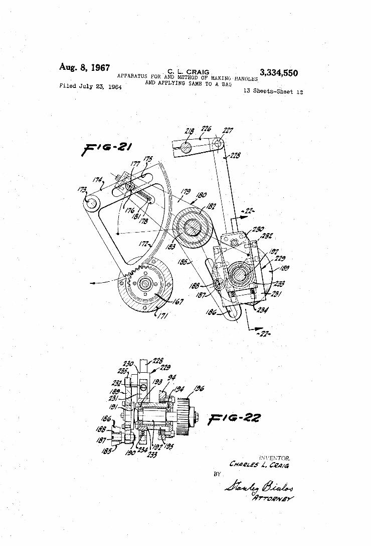
ing assembly for the idler cord~feed roller; FIGURE 21 is a longitudinal sectional view taken along
the line 21-21 of FIGURE 14;

3334550 3
FIGURE 22 is a broken vertical sectional view taken along the plane 22-22 of FIGURE 21; FIGURE 23 is a broken hybrid sectional view taken
along the plane 23-23 of FIGURE 19; FIGURE 24 is a broken horizontal sectional view taken
along the plane 24-24 of FIGURE 23; FIGURE 25 is a broken hybrid sectional view taken
along the line 25-25 of FIGURE 5; and FIGURE 26 is a broken horizontal sectional view taken
along the plane 26-26 of FIGURE 25.
General explanation
The general or overall system for forming a pair of handles and for applying the same to a bag will ?rst be described brie?y with particular reference to FIGURES 1 through 4. In the usual instance, the bags to which a pair of handles are to be applied are formed of paper, and have a closed bottom and an open top. Such bags generally have a single-wall thickness although where desired, multiple-wall bags may be used. Ordinarily, the bags are made of paper, but they could be formed of some other material. Similarly, the handles being applied to such bags are made of paper cording although they cer tainly could be formed of ?ber rope or some other suit able material. A completed shopping bag is illustrated in FIGURE 3 and is designated generally with the let ter B.
Such typical bag B is seen to have a pair of side walls 50 and 51 integrally interconnected at the opposite edges thereof by gussets 52 and 53. In the speci?c illustration, the bag B is a single-wall bag formed of paper and made in the usual manner on conventional bag~making ma chinery. The upper end of the bag is open, and respec tively secured to the side walls 50 and 51 are looped handles 54 and 55. The handles are identical and each is adhesively secured to its associated side wall by a tape strip or fastener strip 56. Each strip 56 is deformed transversely at spaced apart locations therealong to pro vide channels 57 and 58 that respectively receive therein the opposite legs of the associated handle, which legs for identi?cation are designated 59 and 60‘. The handle, or particularly the legs 59 and 60 thereof, are adhesively secured to the fastener strip 56 and also to the outer surface of the adjacent bag wall. The fastener strip 56 along its length is also adhesively secured to such bag wall. The longitudinal axis of each fastener strip 56 is sub
stantially normal to the longitudinal axis (i.e., top to bottom) of the bag B, and in particular to the axes of the associated side walls 50 and 51 thereof; and in that the legs 59‘ and 60 of the handle are transversely dis posed and are generally normal to such axis of the as sociated fastener strip 56, the axes of such legs extend along and are generally parallel to the longitudinal axis of the bag. Therefore, the force transmitted between the handles and bag when a properly loaded bag is carried by the handles is essentially a tensile force directed along the planes of the side walls 50‘ and 51. The direction of such force transmission takes advantage of the relatively great strength of paper in tension and correspondingly minimizes the transmission of angularly disposed shear or tear-producing forces between the handles and bag walls. A supply of bags or sacks before handles are affixed
thereto is fed to the apparatus by hand or by automatic infeed mechanism (not shown), and such bags are suc cessively advanced one-by-one through the apparatus. In FIGURE 1 a stack 61 of bags is shown located at the infeed or entrance of the apparatus, and the bags are ad vanced forwardly therefrom by a conventional conveyor equipped with spaced ?ights each of which engages a bag along a gusset edge thereof and advances the same through the apparatus. Such conveyor has been omitted from the illustration in FIGURE 1 for purposes of clarity of detail, but is shown in FIGURE 9 and is designated
10
15
30
40
45
60
65
70
75
4' .
generally with the letter C. Although the conveyor may be conventional, it will be described in further detail hereinafter. The apparatus is essentially both functionally and
structurally symmetrical above and below the horizontal longitudinal center thereof because it is required to form two separate handles for each bag and then respec tively apply such handles to the side walls 50 and 51 thereof which are horizontally disposed and oriented in vertical juxtaposition as the bag is advanced through the apparatus along such longitudinal center line thereof. Thus, one of the symmetrical sections of the apparatus forms the handle 54 and applies it to the side wall 50 of the bag, while the other symmetrical section forms the handle 55 and applies it to the side wall 51 of the bag. The upper section of the apparatus comprises a plurality of components including a handle-forming component generally denoted with the letter H, a component F‘ for making each fastener strip 56 that secures the upper handle to the side wall 51 of a bag, and an assembly mechanism generally designated with the letter A for applying the upper handle 55 and tape strip 56 to a bag. As indicated, the lower section of the apparatus is essentially sym metrical relative to such upper section, and the respec tively corresponding components are denoted with the letter H’, F’ and A’. A pair of conveyor belts extends rearwardly from the
assembly components A and A’ along the longitudinal axis or horizontal center line of the apparatus, and coop erates with the aforementioned conveyor C in advanc ing the bags toward the discharge station of the ap paratus. In particular, such belts (denoted 62 and 63 for positive identi?cation) are used to apply a compressive force to‘each bag, the handles and fastener strips thereon, while the adhesive used to join such elements is afforded time to set. Thus, the adjacent stretches of the belts move in the same rearward direction in substantially contiguous relation.
In a sequence of operations, a continuous length of cording 64 is withdrawn from a parent roll 65 and is advanced through a tension- and size-sensing assembly 66 to a handle-forming station 67 at which the cording 64 is made into looped handles 55. As each such handle 55 is formed, it is severed from the continuous length of cording by a cutting or knife assembly 68 preparatory to applying the handle to a bag. In a somewhat similar manner, a continuous strip of tape 69 is withdrawn from a supply roll 70 and is advanced through a printer 71 at which, if desired, indicia such as advertising may be ap plied to the tape. From the printer 71, the continuous tape is advanced through a cutting station 72 at which it is cut into lengths corresponding to the fastener strips 56. Each such cut strip is then positively advanced by a transfer or guide roller 73 and onto a predetermined surface portion of a transfer and assembly drum 74. The transfer roller 73 has a peripherally interrupted surface and cyclically de?nes a nip with each such surface por tion of the assembly drum to successively transfer each fastener strip thereto. The tape strip is held on or clamped to each such predetermined surface portion of the drum 74 at spaced apart locations therealong by vacuum suction means, as will be described hereinafter. The drum advances each tape strip through a ?rst ad
hesive-applying station 75 whereat an adhesive pattern consisting of a plurality of spaced apart adhesive stripes are applied to the tape strip along the length thereof. The drum 74 also advances each tape strip through a slack-producing station 76 (FIGURE 4) at which the strip is deformed transversely by providing a rib '77 there across. The material forming such rib is subsequently em ployed to provide the aforementioned channels 57 and 58 that respectively receive the legs 59 and 60 of the handle 55 therein. The legs 59 and 60 of the looped handle 55 are then brought into engagement with the tape strip 56; and in particular, the leg 59 is pressed against the tape

3,334,550 strip 56 and is displaced therewith into a ?rst clamping station 78, and subsequently the leg 60 and tape strip are displaced into a second clamping station 79. Such dis placements of the tape strip 56 at the clamping stations form the channels 57 and 58 and, as stated, the material requisite for such channels is taken from and constitutes the material which comprised the rib 77.
Next, the drum 74 advances the handle-equipped tape strip 56 through a second adhesive-applying station 80 at which an additional pattern of adhesive is applied to both the tape strip and juxtaposed legs 59 and 60 of the looped handle 55. Such second adhesive pattern com prises a plurality of spaced apart stripes which are offset with respect to and therefore interposed between or inter laced with the prior deposited stripes. Thus, the handle 55 is adhesively secured to the tape strip 56 by the ?rst glue pattern applied at the station 75, and it will also be adhesively secured to the side wall 51 of the bag B by the adhesive pattern applied at the station 80. The tape strip 56 will be adhesively secured to the bag by the entire adhesive pattern deposited at the two stations 75 and 80‘. As the drum 74 further advances the handle-equipped tape strip 56 past the second adhesive station 80, such tape strip is brought into engagement with the side wall 51 of a bag that is advanced beneath the drum 74 in timed relation with the rotational movement thereof. The tape strip is thereby adhesively secured to such bag, which is then advanced into the grip of the conveyor belts 62 and 63 that press the tape strip and handle against the bag while the adhesive cures. As indicated hereinbefore, the apparatus is function
ally symmetrical in the sense that a lower handle 54 must be applied to each bag B along the underlying side wall 50 thereof; and to effect this result, the ap paratus includes the handle-forming mechanism H’, the fastener-forming mechanism F’ and the assembly mech anism A’. These mechanisms comprised in the lower section of the apparatus respectively correspond to the mechanisms H, F and A heretofore described and will not, therefore, be further elaborated. Wherever con’ venient in FIGURE 1 and elsewhere in the drawings, the primed form of the numerals ‘used in connection with the description of the mechanisms H, F and A will be applied to the respectively conresponding components in the mechanisms H’, F’ and A’.
The fastener-forming mechanism In further elaborating the fastener-forming mechanism
F, and again noting that the fastener-forming mechanism F’ is substantially identical thereto, reference will be made in particular to FIGURES 1, 4, 5, 6 and 7. As shown in FIGURE 1, the endless strip of webbing 69 is with drawn from a supply roll 70 rotatably supported upon any conventional and suitable backstand (not shown). In being withdrawn from the supply roll, the continuous strip of webbing is pulled over a plurality of guide rollers, such as 81 and 82, and through the printer 71 by feed rollers 83 and 84,. The aforementioned knife 72 operates in timed relation with the advancement of the webbing 69 to sever the same transversely into fastener strip lengths. Each such strip (as shown best in FIGURE 6) is directed by a stationary guide 85 and the roller 73 onto the surface of the transfer and assembly drum 74. Such drum has a pair of strip-receiving segments 86a and 86b which are diametrically oriented and have surface por tions that are elevated slightly with respect to the re maining circumferential surface of the drum. Each of the elevated segments 86a and 86b may be
slightly shorter in angular length than the strips 56 laid therealong, as shown in FIGURE 6; and each such seg ment is provided intermediate the ends thereof with a transversely extending recess or groove 87 (the su?‘ix a being used to denote each of the parts or components functionally and structurally associated with the segment 86a, and the suffix b being used to denote those asso
10
15
20
25
30
35
40
45
55
60
65
70
75
6 ciated with the segment 861)). It may be noted that the grooves 87a and 87b are diametrically oriented, and equally spaced therebetween are two additional grooves 870 and 87d which, although not employed directly in making fastener strips 56, accommodate structure located at the slack~producing station 76. More particularly, each of the tape strips 56 is de
pressed into the underlying groove 87a or 87b (as shown in FIGURE 7) at the slack-producing station 76 by a rotatable presser member comprising a holder 88 mount ed upon a shaft 89 so as to rotate therewith and being equipped with a presser ?nger 90 which (as shown in FIGURE 9) de?nes a plurality of ribs or projections 91 equally spaced from each other transversely by interven ing grooves or depressions 92. The angular velocities of the drum 74 and presser member are so synchronized and related that the presser ?nger 90 aligns with and moves into each of the grooves 87 as the drum and presser member rotate. FIGURES 4 and 7 illustrate the drum and presser member in relative positions such that the presser ?nger is extended into a groove 87 aligned there with.
Evidently, the presser ?nger is effective to displace a tape strip 56 downwardly and into the underlying groove 87a in one instance and into the groove 87b in the other instance, and FIGURE 7 in particular illustrates one such occurrence. The grooves 87c and 87d are provided along the drum 74 simply to accommodate the presser ?nger 90 which makes four complete rotations for each single rotation of the drum 74. It is apparent that the angular extent of the tape strip 56 along the circum ferential surface of the drum 74 is diminished by dis placement of the tape strip into the underlying groove 87, and this change in extent is seen by comparing FIG URES 6 and 7, for example. Each of the tape strips 56 is held against the surface
of the drum 74, and in particular against the underlying surface of the associated segment 86, by vacuum clamp ing means. In describing such vacuum clamping means, it will be advantageous to ?rst consider to some extent the structural composition of the drum ‘74; and for such description, FIGURES 5, 6 and 9 are perhaps most ap propriate. The drum is rotatably driven from a main drive shaft 93 journalled for rotation in the frame struc ture of the apparatus which includes spaced apart frame elements 94 and 95 that respectively carry bearings 96 and 97 which support such shaft for rotation. The main shaft 93 intermediate the frame elements 94 and 95 passes through a gear box 98 containing a Worm and pinion drive, generally indicated as 99, by means of which the shaft is rotated. The input to the gear box constitutes a shaft 100 rotatably driven by the prime mover of the apparatus which is not shown for purposes of simpli?ca tion because it is completely conventional and in the usual instance will be an electric motor. The shaft 93 passes outwardly through the frame ele
ment 94 and through a gear housing 101 bolted or other— wise rigidly secured to the frame element and which is equipped with a bearing 102 that journals the shaft for rotation relative to the housing. Keyed to the shaft 93 exteriorly of the gear housing 101 is a hub 103, which therefore rotates with the shaft. The hub 103 has a ?ange 104 extending radially outwardly intermediate the ends thereof, and abutting the outer surface of such ?ange in circumjacent relation with that portion of the hub 103 disposed outwardly of the ?ange is a collar 105 com prised by the drum-74. The collar 105 is ?xedly clamped to the ?ange 104 by a plurality of bolts 106 that extend axially through the collar and ?ange and are threadedly received in tapped openings provided therefor in a clamp ing ring 107 which abuts the ?ange 104 on the inner side thereof. As shown in FIGURE 10, the openings 108 pro vided in the ?ange 104 and through which the bolts 106 extend are angularly elongated so as to permit slight angular adjustments of the drum 74 relative to the drive shaft 93 for timing and alignment purposes.

3,884,550 Formed integrally with the collar 105 and extending
radially outwardly therefrom intermediate the ends there of is a web 109 that terminates at its outer extremity in a ?ange or rim generally indicated as 110; and, as shown best in FIGURES 5 and 6, the ?ange 110 is radially enlarged to form the aforementioned strip-receiving seg ments 86a and 86b. Disposed along the outer side of the web 109 is a stationary vacuum manifold 111 having an inlet 112 adapted to communicate with a vacuum source or a source of reduced pressure (not shown) through a coupling 113 secured to the manifold 111 and a conduit 114 (FIGURE 5) connected with the coupling 113 and clamped by bracket structure 115 to the frame element 94. The inlet 112 is in open communication with a radially extending ?ow passage 116 provided in the manifold 111, and the passage 116 at its outer end opens into an enlarged port 117 provided by a stationary ring 118 mounted upon the manifold 111 in circurnjacent rela tion with an inner end portion thereof. The precise an gular orientation of the ring 118 and manifold 111 is determined by a key 119 so that in assembling the appa ratus, communication between the passage 116 and port 117 will be assured and thereafter relative rotation there between prevented. The ring 118 has a relatively short axially extending
?ow passage 120 therein that communicates at its outer end with the enlarged port 117 and at its inner end in an angularly elongated channel or chamber 121 which, as shown best in FIGURE 11, has a length somewhat in excess of 180°. Fixedly secured to the web 169 of the drum 74 by a plurality of cap screws 122 (as shown in FIGURE 6) is an annular wear ring 123 having an outer face that slidably engages the inner contiguous face of the stationary ring 118. The wear ring 123, which is ro tatable relative to the stationary ring 118, has two angu larly spaced pairs of ?ow ports opening through such outer face. As shown best in FIGURE 6, such pairs of ports are respectively associated with the segments 86a and 86b and are respectively denoted with the numerals 124a—125a and 124b-125b. Such paired ?ow ports are also indicated diagrammatically in FIGURE 11 in rela tion to the stationary ring 118 although the wear ring is actually concealed in FIGURE 11. The wear ring 123 is also provided with a plurality of
relatively short and angularly extending ?ow passages re spectively communicating with the associated ports 124 ‘I and 125. Accordingly, a passage 126a communicates with the port 124a, and a passage 127a communicates with the port 125a; and similarly, passages 126b and 127b respec tively communicate with the ports 1243b and 12%. Each of the passages 126 and 127 has an outwardly turned end portion that communicates with an associated ?ow pas sage provided through the drum 74 and, in particular, through the web 109 and ?ange 110 thereof. In speci?c terms, such passages are denoted with the numerals 128a, 129a, 128b and 12912, and they respectively communicate with the passages 126a, 127a, 12612 and 12717. In FIGURE 11, such ?ow passages 128 are illustrated diagrammati cally in order to orient the same with respect to the di agrammatically illustrated wear ring 123 and web 109 and ?ange 110 of the drum '74. As shown most clearly in FIGURES l2 and 9, each of
the passages 128 opens outwardly along the circumferen tial surface of the drum; and in particular in each of these ?gures, the passage 1280 is thusly illustrated. In terms of precise structure, the outer circumferential surface of the drum 74 or ?ange 110 thereof has a channel network— one of which is shown in FIGURE 12 and denoted with the numeral 130a. The function of the network 130:: is to provide reduced pressure across a signi?cant portion of the drum surface, and this is accomplished by having the passage 128a communicate with the network 130a. Evi dently, each of the passages 12% and 129 will open into such a channel network.
10
20
25
30
410
50
(30
From the foregoing description, it will be evident that as the main shaft 93 is continuously rotated, the drum 74 will be continuously rotated since it is ?xedly related thereto through the collar 105 and hub 103. When the conduit 114 is connected to a vacuum source, reduced pressure will be present in the manifold port 112, and through the passage 116, port 117 and passage 120 in the arcuate channel 121. In that such channel 121 is station ary, and is therefore traversed by the wear ring 123 car ried by the drum 74, the various ?ow ports 124 and 125 will be successively rotated into facing relation with (and therefore open communication with) the channel 121.
Referring to FIGURE 11, with the wear ring 123 in the instantaneous angular position shown, the flow ports 125b and 124a are both in communication with the chan nel 121, the ?ow port 125a is about to rotate into com munication with the channel and the ?ow port 12417 has just been rotated out of communication with the chan nel-—-the wear ring 123 rotating in the direction of the arrows relative to the stationary channel 121. Thus, a reduced pressure is present in the channel network 130a communicating with the port 124a through the passages 128a and 126a; and similarly, the channel network so connected with the passage 12% will be at reduced pres sure. Consequently, in this angular position of the drum any fastener strip disposed along the segment 86a will have its leading edge clamped to the circumferential sur face of such segment by the channel network 130a, and any tape strip extending along the segment 86b will have its trailing end portion clamped to the circumferential surface thereof. As the drum continues to rotate in a counterclockwise
direction, the tape strip 56 extending along the segment 86a will be clamped thereto at both ends at the time the drum brings the port 125 into communication with the channel 121. At about this same time, the port 125b will be rotated out of communication with the passage 121, and the tape strip 56 extending along the segment 86b will then be free to be withdrawn therefrom. Although the tape strip may fall freely from the underlying segment once the vacuum has been removed, it may be desirable to provide stationary stripper ?ngers 131, as indicated in FIGURE 6, to assure separation of the tape strip from the drum.
In this same respect, the stationary ring 118 (as shown in FIGURES 9 and 11) is provided with a bleed or ex haust port 132 located just beyond the terminal end of the channel 121 which has an inwardly facing inlet adapted to successively communicate with each of the ports 124 and 125 in the wear ring 123 so as to provide atmospheric pressure at each channel network 130 as such networks are successively brought into ?ow communication with the exhaust port-which communication is established just prior to the tape strip being removed from the underlying segment 86 at the stripping station de?ned by the stripper ?ngers 131. The fastener strip-forming section of the apparatus also
includes the aforementioned ?rst glue-applying station 74 at which an adhesive pattern consisting of a plurality of spaced apart adhesive stripes are applied to each fastener strip 56 subsequent to its being laid onto a drum segment 86. The glue-applying station may be conventional in a structural sense and includes an adhesive-applicator cylin der or roller 133 supported for rotation in a yoke or frame 134. For purposes of the present invention, the ad hesive applicator structure may be of the transfer roll type or it may be of the extrusion type as, for example, the ex trusion applicator disclosed in the copending application of Rudolf Weis, Serial No. 246,518, ?led December 21, 1962. In either event, the cylindrical surface 135 of the applicator roll is provided with a plurality of spaced apart ribs or ridges adapted to effectively engage the surface of a fastener strip 56 and deposit the aforementioned strips of adhesive therealong. The spaces or gaps between such adhesive stripes on the fastener strip correspond to the

3,334,550 9
spaces between such ribs or ridges along the surface 135 of the applicator roll.
In the adhesive applicator structure shown in FIGURE 5, the roll 133 and yoke 134 :may be pivoted in a clock wise direction about the shaft 136 to remove the roller 133 from adjacency with the drum 74 for cleaning and other maintenance purposes. Further, the applicator struc ture includes adjustment means ‘for accurately positioning the cylindrical surface ‘of the applicator roll 133 with respect to a fastener strip 56 passing there under; and in that such strip is supported along the surface of one or the other of the segments 86 (each surface of which is disposed radially outwardly of the remaining circum~ ferential surface of the drum), the roll 133 is normally spaced from the drum surfaces intermediate the segments 86. However, the roll 133 is cyclically oscillated or lifted away from the drum 74 and then returned thereto in a time relationship such that the application of the adhesive stripes commence and terminates about 14 inch from the respective ends of each fastener strip. This is to prevent the adhesive from overrunning the fastener strips. Such oscillatory movement of the applicator roll is conven ional and is ordinarily obtained by cam structures, not shown. As mentioned hereinbefore, the presser ?nger 90 at
the slack-producing station 76 has a serrated surface, as shown best in FIGURE 9, comprising a plurality of spaced apart ribs 91 which are separated from each other by spaces 92. The ribs 91 and spaces therebetween are so oriented with respect to the adhesive stripes along a fastener strip 56 (and, therefore, with respect to the ribs and gaps along the cylindrical surface 135 of the applica tor roll 133) that the ribs 91 align with the gaps between adhesive stripes, and the spaces or recesses 92 respectively align with the ,adhesive stripes. Consequently, as the presser ?nger 90 engages a fastener strip 56 to displace the same downwardly and into a groove 87, the adhesive stripes are not smeared by engagement of the presser ?nger therewith.
In an operational sequence in which a tape strip 56 is formed in preparation to having a handle 55 adhesively secured thereto, the relatively narrow Webbing 69 is with drawn from the supply roll 70 by the feed rolls 83 and 84 and, if desired, indicia of appropriate character is printed along one surface of the strip by the printer 71. The knife 72 is operated in timed relation with the ad vancement of such strip 69 to sever the same into fastener strip lengths. Each such length is applied to the rotating assembly drum 74 by advancing the fastener strips one by-one through the structure including the guide 85 and roller 73; and the movements of the drum 74, roller 73 and continuous webbing 69 are such that each fastener strip 56 is laid along one or the other of the segments 860 or 86b.
Shortly after the forward end portion of a tape strip 56 is laid along the leading end portion of such segment 86, the leading vacuum port 124 of the wear ring 123 (which is affixed to and rotates with the drum 74) is advanced into alignment and ?ow communication with the channel 121 in the stationary ring 118 secured to the vacuum manifold 111. As a result of such ?ow communication, a reduced pressure is established in the channel network 130 connected with such vacuum port 124, whereupon the leading end portion of the fastener strip 56 is vacuum clamped to the outer surface of the underlying segment 86 of the assembly drum 74. At about this same time, and usually just following such
vacuum-clamping of the leading end portion of the fas tener strip to the segment 86, the leading end thereof is advanced through the adhesive applicator station 75 at which the glue stripes commence to be applied to the outj wardly oriented surface of the fastener strip. As the strip continues to be advanced by the drum 74, additional lengths of the strip are laid along the segment 86, and such lengths are subsequently advanced through the adhe
10
15
20
25
30
10 sive~applying station. Ultimately, the midportion of the segment 86 advances into the slack-producing station 76, and the angularly advancing groove 87 and presser ?nger 90 come into alignment, at which time the presser ?nger displaces the strip 56 downwardly and into the groove 87, as shown in FIGURE 7. At approximately the same time, and usually just fol
lowing this operation, the vacuum port 125 which com municates with the trailing channel network 130 is ad vanced into alignment and ?ow communication with the channel 121 in the stationary ring 118, whereupon the reduced pressure then present in such channel network vacuum-clamps the trailing end portion of the fastener strip 56 to the surface of the segment 86. As the drum 74 further carries the tape strip in a counterclockwise direc tion (as viewed in FIGURE 6), the entire length of the strip passes through the adhesive-applying station 75 and, as will be described in detail hereinafter, a looped handle 55 is thereafter applied to such tape strip and it is de formed as shown at 57 and 58 (FIGURE 3) to receive the legs 59 and 60 of such handle. An additional glue pat tern is then applied to the tape strip 56 at the second ad hesive-applying station 80, and ?nally, the handle~ equipped fastener strip is carried to the bottom of the drum 74 and into the position generally indicated by the segment 86b in FIGURE 6, at which time the strip is re moved from the drum and is applied to an underlying bag. As part of this last operation, the leading vacuum port
124 advances into alignment and flow communication with the bleed or exhaust port 132, whereupon the vacuum~ clamp securing the leading end of the strip 56 to the seg ment 86 is destroyed and such leading end of the strip may be deposited onto an underlying bag. Ultimately, the trailing vacuum port 125 similarly is advanced into ?ow communication with the bleed port 132, whereupon the trailing end portion of the strip 56 is released from the segment 86 and can be removed from the drum. While
' such removal of a handle~equipped tape strip 56 is taking
40
55
75
place, another tape strip 56 is being laid along the oppo site drum segment 86, an adhesive pattern is being ap plied to such tape strip at the station 75, and the tape strip is being deformed into the groove 87, all as hereto fore described.
The handle-forming mechanism
In describing the handle-forming mechanism H, refer ence will be made in particular to FIGURES 1, 2, 4, 5, 9 and 13 through 26. As illustrated in these ?gures, the cording 64 is intermittently withdrawn from the parent roll 65 at the rate at which it is required for forming han~ dles 55; and as the cording is withdrawn from such parent roll, it passes through the aforementioned tension-and size-sensing assembly 66. As shown in FIGURE 2, the as sembly 66 includes a sheave or idler roller 137 rotatably supported adjacent an end portion of a bracket or bifur~ cated support arm 138 pivotally carried adjacent the opposite end portion thereof by mounting structure 139. The arm 138 is resiliently biased in a clockwise direc tion relative to the pivotal support therefor by a helical spring 140; and, therefore, the roller 137 serves as a take up device for the cord 64. A second idler roller equipped with a cam 141 is in
tended to be rotated by the cording 64 advancing there over, and the cam is provided therealong with a lobe that repetitively engages the movable contact 142 of a switch 143 to cyclically close the same. The switch is connected in the power circuit of the machine through time delay means so that if the switch 143 is not periodically closed at or faster than a predetermined rate (every few seconds in a typical embodiment of the apparatus), the power cir cuit will be interrupted and the machine de-energized. In the usual instance, such time delay means will constitute a stop motion control device as, for example, the com merically available device known as the Farmer CK Timer.

3,334,550 11
Evidently, so long as the cording 64 is being properly withdrawn from the parent roll 65, the switch 143 will be repetitively opened and closed at a cyclic frequency sufficient to satisfy the time requirements of the stop mo tion control device. Ordinarily, this condition will be satis?ed as the cord feed assembly (indicated diagram matically at 144 in FIGURE 2) intermittently advances successive predetermined lengths of cording. However, should the cording become depleted (i.e., no cord) or a jam develop (i.e., no advancement of the cording), the machine ‘will be deenergized because the cam 141 will not be rotated and the switch 143 will not be cyclically opened and closed. This same type of depletion-jam de tector can be used in association with the webbing or tape strip 69, but is not illustrated in the drawings for purposes of simplifying the disclosure. The cording 64 is further advanced through a size de
tector 145 comprising a part of the mechanism 66. The size detector includes an arm 146 supported adjacent one end thereof for pivotal movement about a pin 147. Adja cent its opposite end, the arm 146 is equipped with a tube 148 of predetermined diameter through which the cording 64 passes. The arm is ‘biased in a counterclock wise direction by a helical spring 149, and it is connected to the movable contact 150 of a switch 151 which has a ?xed terminal 152 adapted to be engaged by the con tact 150. The switch 151 is connected in the power circuit of the apparatus, and when the switch is opened it breaks such power circuit to deenergize the apparatus.
Ordinarily, the switch 151 is biased into the closed posi tion thereof by the spring 149, and the tube 148 is su?i ciently large relative to the cording 64 that the cording passes freely therethrough. However, should the diam eter 0f the cording suddenly enlarge, as where it has a knot therea-long, the cording is thereby prevented from passing through the tube 148, whereupon the tube is dis placed in a clockwise direction against the biasing force of the spring 149, and the switch 151 is thereby opened. Thus, in a practical sense, the size detector 145 is a knot detector and functions to terminate operation of the apparatus whenever a knot appears along the cording which has some lateral or radial dimension in excess of the minimum accommodated by the tube 148. The feed roll assembly 144, as shown best in FIGURE
19, comprises a pair of rotatable drive rolls 153 and 154 each of which has a circumferential groove or chan nel thereabout which conforms generally to the con tour of the cord 64. The rolls 153 and 154 are mounted so that the channels therea-long are in alignment, and they are disposed in adjacency so as to frictionally pass the cord 64 therebetween. The roller 153 is an idler and, as shown best in FIGURE 20, is mounted upon a shaft journalled for rotation in suitable bearing structures mounted in a casing 155 supported intermediate the ends thereof on a pin 156 for pivotal adjustments thereabout. Threadedly mounted within the lower end portion of the casing 155 is an adjusting screw 157 that seats against one end of a helical spring 157’ bearing at its opposite end against a housing 158 that supports the pivot pin 156. The helical spring 157' resiliently biases the casing 155 in a clockwise direction to urge the idler feed roller 153 against the driven feed roller 154. The screw 157 is a loading device and, evidently, if the screw is rotated in one direction, the casing 155 tends to be displaced in a clockwise direction about the pin 156 which increases the nip force de?ned between the roller 153 and roller 154, and rotation of the screw 157 in the opposite direc tion decreases the magnitude of such nip. The roller 154 is intermittently driven, and during each
cycle of operation thereof it advances a length of cord ing 64 sufficient to form one looped handle 55. Referring to FIGURE 15 in particular, it is seen that the roller 154 is clamped by a nut 159 and bearing structure 160‘ to a shaft 161 journalled at one end for rotation relative to the housing 158 by the bearing structure 160, and jour
10
30
45
55
60
65
70
75
12 nalled adjacent its other end in bearing structure 162. The nut 159 is received upon the threaded end of the shaft 161 and clamps the roller 154 and bearing structure 161} against a shoulder de?ned along the shaft.
Adjacent its lower end portion, the shaft 161 is equipped with a pinion gear 163 which is driven by a bevel gear 164 constrained upon the output shaft 164 of a one-way clutch mechanism 166 having a drive gear 167 de?ning the input thereto. The one-way clutch mechanism 166 is mounted within a casing 168 secured to the frame element 94, and the output shaft of the clutch mechanism extends through such frame element and is supported for rotation with respect thereto on bearing structure 169. The gears 163 and 164 are mounted within a housing 170 secured by cap screws to the frame element 94, and the housing 170 provides an extension of the housing 158, which is also ?xedly secured to the frame element 94 by cap screws. The one-way clutch assembly 166 may be completely
conventional and, as is well known, rotates the output shaft 165 thereof in one predetermined direction when the input gear 167 is rotated in a predetermined direction. However, when the input gear 167 is rotated in the op posite direction, no output torque is delivered by the one-way clutch to the output shaft 165 thereof. The cas ing 168 for the one-way clutch assembly comprises a plurality of separable components and includes a com ponent 171 which is open along the backside thereof, as viewed in FIGURE 15, so as to expose a portion of the input gear 167 for meshing engagement thereof with a sector gear 172, as shown most clearly in FIGURES 19 and 21. As seen best in FIGURES 13 and 21, the sector gear
172 is mounted upon a shaft or pin 173 for pivotal recip rocations about the longitudinal axis thereof, and the pin 173 is supported by the frame element 94. The sector gear 172 has an arcuate length in the order of 90°, and along one extremity thereof is provided with a leg 174 having an elongated slot 175 therein that extends radially out wardly from the pivot shaft 173. Mounted within such slot 175 is a roller 176 supported for rotation upon a pin 177 that extends transversely through an elongated slot 178 provided in one leg 179 of a bell crank 180. A rela tively long adjusting screw 181 extends longitudinally into the slot 178 and through a tapped opening provided therefor in the pin 177. Consequently, the location of the pin 177 along the slot 178 can be selectively deter mined by suitable adjustment of the screw 181. Such ad justment of the pin 177 determines the throw or length of the arcuate reciprocation of the sector gear 172. The bell crank 180 is supported for angular displace
ments upon an annular wear bearing 182 (FIGURES 15 and 21) located circurnjacent a reduced end portion of an elongated sleeve 183 that extends through the frame or other suitable means. The bell crank is con?ned upon element 94 and is rigidly secured thereto by cap screws the sleeve 183 and bearing 182 by an abutment element 184 which is af?xed to the sleeve by cap screws. The oppo site leg 185 of the bell crank is provided with an elongated slot 186 therealong extending radially outwardly from the axis of rotation of the bell crank. Mounted within the slot 186 for slidable displacements therealong and being rotatably supported upon a pin 187 is a roller 188. The pin 187 extends through and is secured to a cam 189 so as to rotate therewith by a nut 196 threadedly received on the end of the pin. The cam 189 is ?xedly secured by cap screws to the
end plate 191 of a shaft 192 journalled in spaced apart bearing structures 193 and 194 for rotation relative to a collar 195 that extends through the frame element 94 and is ?xedly secured thereto by cap screws. The shaft 192 extends beyond the collar 195 and frame element 94, and has affixed to the outer end thereof a pinion gear 196 which (as shown in FIGURE 14) is driven by a drive gear 197 ?xedly secured to the main shaft 93. The drive

3,334,550 13
gear 197 and pinion gear 196 driven thereby are both mounted within the gear housing 101, and, as shown in FIGURE 9, the gear 197 is keyed to the shaft 93 so as to rotate therewith.
In a cycle of operation of the described gear train, the main shaft 93 is continuously rotated as is the drive gear 197 secured thereto. As a consequence, the pinion gear 196 is continuously driven as is the shaft 192 on which it is mounted and the cam 189 carried by the shaft. Therefore, the roller 188 which is mounted upon the cam 189 continuously describes a circular path about the axis of rotation of the shaft 192. The roller 188 in being constrained within the elongated slot 186 of the arm 185 of the bell crank 180 causes such bell crank to recipro cate about the pivotal mounting therefor; and necessarily then, the roller 176 carried by the opposite arm 179 of the bell crank describes an arcuate path, the center of which is the pivotal axis of the bell crank. 'The roller 176 is constrained within the elongated
slot175 of the gear sector 172, and thereby causes such gear sector to reciprocate about the axis de?ned by the pivot shaft 173 upon which it is supported. Therefore, the drive gear 176 de?ning the input to the one-way clutch 166 is cyclically reciprocated in opposite directions in accordance with the direction of motion of the gear sec tor 172. Through the mechanism of the one-way clutch, such reciprocable movements in one direction only of the input gear 167 are transmitted to the output shaft 165 and through the gears 164 and 163 and shaft 158 to the drive roller 154 of the cord feed mechanism ‘144. The corresponding rotational movement of the feed roller 154 causes it to advance a length of cording sufficient to form a looped handle 55. Reciprocable displacements of the input gear 167 in the opposite direction are ineffec tive, because of the one-way clutch mechanism, to im part‘rotational movement to the output shaft 165; and consequently, the drive roller 154 is not rotated during such reciprocable movements.
_ In being so advanced by the feed rollers 153 and 154, the cord 64 is guided through a tube 198 that passes through and is supported by the frame element 94, as shown‘ most clearly in FIGURE 15. The discharge end of the guide tube 198 (FIGURE 23) terminates adjacent the‘ feed‘rollers 153 and 154;‘and as the cording is dis charged frornbetween such rollers, it enters a tubular guide’ 199 that is ?xed in position relative to a support 200 by a set ‘screw 201. The support 200 is ?xedly related to the frame element 94 (as shown in FIGURE 15), and anchored to the support by a key and cap screw 202 is the'knifeassembly 68.
i The knife assembly includes a stationary bracket 203 ?xedly secured to the support structure 200 by the combi nation of such key and cap screw 202 and a dove tail connection (FIGURE 24), and fastened to the bracket 203 by a plurality of cap screws is a stationary guide 204. The guide 204 passes through a longitudinally extending channel 205 provided in a knife carrier 206 mounted for reciprocable displacements relative to the bracket 203 and guide 204 and having af?xed thereto adjacent its lower end by a cap screw 207 an upwardly facing cutting blade 2_08._ The blade 208 slides against an anvil plate 209 fixed by a cap screw 210 to the guide 204. The guide 204 and anvil plate 209 together de?ne an opening 211 there through which is axially aligned with the passage through the tube 199. The lower end portion of the knife carrier 206 is cut out or recessed as shown at 212 (such recess being the lower extremity of the channel 205) to enable the same to reciprocate ‘without interference from the anvil plate 209 and adjacent portions of the guide 204. The knife carrier 206 is resiliently biased downwardly to ward the lowermost position thereof (which is shown in FIGURES 23 and 19) by a helical spring 213 that seats at its lower end in a recess 214 provided in the knife holder and seats at its upper end within a recess 215 provided in the stationary support 203.
20
25
30
50
55
70
14 As seen best in FIGURES 18, 19 and 23, the recipro
cable knife holder 206 has an outwardly extending abut ment ledge at its upper end, and a wear block is located thereunder which is carried by a pivot pin 216 connected to an end portion of an arm 217 which adjacent its oppo site end portion is ‘bifurcated and ?xedly secured thereat to a shaft 218 journalled for pivotal movements in spaced bearings respectively carried by the frame element 94 and by a frame bracket 219 rigidly related thereto (FIG URE 5). Freely mounted upon the shaft 218 so as to ro tate relative thereto is a link 220 (FIGURE 8) having at its lower depending end a pin 221 extending laterally there of that is pivotally engaged by a bifurcated end portion 222 of a drive arm 223 provided by a bell crank 224 mounted, _ on a shaft 225 so as to rotate freely relative thereto. The shaft 225 is appropriately journalled for rotation in bear ing structure provided by the frame element 94 and frame bracket 219 (FIGURE 25). As shown in FIGURE 21, the shaft 218 has a drive link
226 ?xedly secured thereto which is operative to effect pivotal displacements of the shaft. The drive link 226 is connected by a pin 227 to a push rod 228 extending downwardly from the drive link 226, and at its lower end the push rod is secured to a perimetric yoke 229 com prising a mounting block 230 which is directly secured to the shaft 228, and a U-shaped guide 231 ?xed to the mounting block 230 by a plurality of cap screws 232. Slidably located within the generally U-shaped guide 231 is a slide block 233 mounted coaxially circumjacent the aforementioned ?xed collar 195 and rotatable with respect thereto. The slide block 233 is smaller in the generallyv vertical direction than the space ‘de?ned within the U shaped guide frame 231, and as a result, the guide is movable in such general direction relative to the slide block. The guide 231 is resiliently ‘biased downwardly relative to the slide ‘block 233 ‘by a plurality of helical springs 234 interposed therebetween which at their upper ends bear against the slide block and at their lower ends against the guide. As seen most clearly in FIGURE 22, the yoke
in particular, the mounting block 230 thereof) is equipped with an outwardly extending cam follower 235 that rides along the peripheral cam surface of the aforementioned cam 189 which is continuously rotated by the shaft 189 drivingly connected to the continuously rotating main shaft 93 through the drive gear 197 and pinion gear 196.
In an operational cycle, the cam 189 is continuously driven from the main shaft 93, as heretofore described; and as a consequence of the cam follower 235 riding on the cam surface of the cam 189, the yoke 229 and push rod 228 are reciprocated generally along the longitudinal axis of the push rod 228. However, because the push rod at its upper end is piv-otally connected to the link 226, which in turn is connected to the shaft 218 and drives the same, the push rod 228 and yoke 229 necessarily pivot slightly relative to the axis of the shaft 192 as they reciprocate. The yoke and slide block connection described permits such angular displacements of the yoke and push rod while affording reciprocable movement thereof.
Angular reciprocable displacements of the link 226 cor respondingly reciprocate the shaft 218 since it is con nected thereto. The arm 217 is also secured to the shaft
229 (and
218 so as to rotate therewith; and, therefore, as the shaft . 218 rotates, the cord-severing knife 208 is reciprocated 1between the lowermost open position illustrated in FIG URES l9 and 23 and the uppermost cord-severing posi tion shown in FIGURE 18. 'It may be noted that the pin 216 and wear ‘block ‘carried thereby are loosely and free ly positioned beneath the outwardly extending abutment ledge of the knife carrier 206 which enables the pin and block to described an arcuate path as the carrier 206 moves linearly. The cam 189 is con?gurated so that the shaft 218, and
in particular the knife 208, are reciprocated in timed re~