APOLLO CRADLES LTD 1.5M DEEP -BEAM TEST REPORT AND …
12
APOLLO CRADLES LTD 1.5M DEEP -BEAM TEST REPORT AND LOAD EVALUATION Alan N White B.Sc., M.Eng., C.Eng., M.I.C.E., M.I.H.T. February 2010 Woodside House 20/21 Woodside Place GLASGOW G3 7QF
Transcript of APOLLO CRADLES LTD 1.5M DEEP -BEAM TEST REPORT AND …

APOLLO CRADLES LTD
1.5M DEEP -BEAM
TEST REPORT AND LOAD EVALUATION
Alan N White B.Sc., M.Eng., C.Eng., M.I.C.E., M.I.H.T.
February 2010
Woodside House
20/21 Woodside Place
GLASGOW G3 7QF

Alan White Design
N0190-003 Page 1 of 12
Table of Contents
Table of Contents ...................................................................................................... 1 Brief ........................................................................................................................... 2 Geometry and Material .............................................................................................. 2 Tests Criteria .............................................................................................................. 3 Tests Description ....................................................................................................... 3 Proof Load Tests Results ........................................................................................... 5
Central point proof load ........................................................................................... 5 Shear proof load .................................................................................................... 7 Proof load acceptance criteria ................................................................................ 7 Proof load test conclusion ....................................................................................... 8
Test to destruction ..................................................................................................... 8 Test to destruction results ..................................................................................... 10 Beam Capacity ...................................................................................................... 11
Summary .................................................................................................................. 11

Alan White Design
N0190-003 Page 2 of 12
Brief
This report describes the tests, as witnessed by Lloyds British Testing Ltd.,
carried out at Apollo Cradles Ltd. in Barnsley, on aluminium 1.5m deep beams,
to confirm that they meet the acceptance criteria.
Geometry and Material
The geometry of the 1.5m beams is as shown below.
The beam is fabricated using aluminium alloy extruded sections in 6082T6.

Alan White Design
N0190-003 Page 3 of 12
Tests Criteria
The criteria were derived to test the beams response to 2kN/m2 loading on a
30m span. The success of the test was measured against the following
criteria:
1. The deflections at the working load are within the serviceability limits for the
structure which is deemed to be L/200 or 150mm.
2. There should be no evidence of non-elastic deformation, instability or other
sign of distress under the working load.
3. Under the proof load, there should not be excessive deflection or any sign of
instability or imminent collapse.
4. The residual deflection measured 15minutes after the removal of the proof
load should not exceed 5% of the measured deflection under the proof load.
Tests Description
Two proof load tests on the beams were made in October, at Apollo Cradles
Ltd offices in Barnsley , UK
For the proof load test, two different load conditions were tested. Firstly a
central point load was applied through a cross beam directly to a pair of Apollo
1.5m deep beams connected and braced at 1m intervals.
To proof test the shear on the beams, a load was applied at 1m from the end
of the braced pair of beams.
These two proof load cases simulate a practical application of bending and an
extreme shear case.

Alan White Design
N0190-003 Page 4 of 12
The layout as constructed comprised a pair of 1.5m deep beams spanning
30m with cross bracing at 1m intervals. The load was applied at the
designated load points using chain pulls. The load amount was determined
using electronic load cells and the deflections recorded throughout the testing.
The test followed the procedures set out in AWD Document N0190-001 Test
Procedures.
A further test to destruction was carried out in December 2009 at Apollo
Cradles offices.
For this test the beam was cantilevered by 15m from a tower and held down at
the rear. The load was applied at 14m from the support and the load applied in
the same manner..

Alan White Design
N0190-003 Page 5 of 12
Proof Load Tests Results
Central point proof load
This load test produces full effects only in the central region of the beam with
the maximum occurring at the centre. Twin X-Beams were used to brace the
main beams at 2m centres and a single X-beam with plan diagonal braces was
provided between them to give bracing at one metre centres on the beam.

Alan White Design
N0190-003 Page 6 of 12
The graph of the test results is shown below.
The graph shows the linear regression trendline of the data from which it is
apparent that there is very little deviation from the line as signified by the
coefficient of determination of the regression R2
which is very close to 1.0, the
perfect fit. So the test has been conducted purely in the elastic region of the
beams response.
The test was conducted in three phases. Firstly a settling down load was
applied which takes up any slack in the joints of the beams. This produced a
permanent set of 1mm deflection at the mid-point.
The second phase was to take the beam to its working load of 60kN in 5
increments of 12kN, hold it at this load and then reduce back to zero load.
This did not produce any residual deflection. At the full load the centre point
deflection was 119mm which is equivalent to L/252.
The third part of the test was to incrementally take the load to the �proof load�
level of 75kN and then unload it. Again this did not produce any residual
deflection.
As an exercise the beam was taken to 100kN without distress, as shown in the
graph.

Alan White Design
N0190-003 Page 7 of 12
Shear proof load
A load at 1m from the end of the structure gives a better indication of an
acceptable shear value for the beam. The double beam was loaded
incrementally to a value of 7840kg without distress.
Proof load acceptance criteria
From BS8118 the acceptance criteria for the proof load test were set out in the
test procedures document. The criteria were derived to test the beams
response to 2kN/m2 loading on a 30m span. They are listed and the results
identified as follows.
5. The deflections at the working load are within the serviceability limits for the
structure which is deemed to be L/200 or 150mm.
The deflection was 119mm which is equivalent to L/252 which is satisfactory.
6. There should be no evidence of non-elastic deformation, instability or other
sign of distress under the working load.
There was no sign of distress or elastic deformation under the working load.
7. Under the proof load, there should not be excessive deflection or any sign of
instability or imminent collapse.
There was no sign of excessive deflection or any sign of instability or imminent
collapse under the proof load.
8. The residual deflection measured 15minutes after the removal of the proof
load should not exceed 5% of the measured deflection under the proof load.
There was no residual deflection after the removal of the proof load.
Alan White Design
N0190-003 Page 8 of 12
Proof load test conclusion
The tests proved conclusively that the Apollo 1.5m deep beams conformed to
the criteria set for acceptance, which were derived to simulate the working load
and proof load for a 2kN/m2 load on a 30m span.
Lloyds British Testing Ltd have issued report certificates 181959/001 to 005 to
confirm that the tests were witnessed and that the beams complied with the
acceptance criteria.
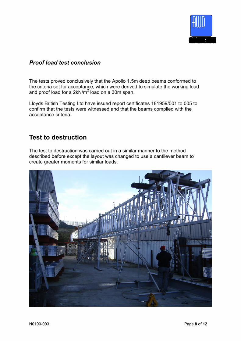
Test to destruction
The test to destruction was carried out in a similar manner to the method
described before except the layout was changed to use a cantilever beam to
create greater moments for similar loads.

Alan White Design
N0190-003 Page 9 of 12
The test was carried out using double reeving of the load up to 6000 kg as
shown in the picture below and then the load removed and the winch triple
reeved to allow for additional loading to be applied.
The deflection of the beam was measured as before at intervals of 1000kg
loading until the beam failed by buckling of the compression boom at the point
of highest moment.

Alan White Design
N0190-003 Page 10 of 12
Test to destruction results
The results of the test are as shown in the graph below:
The graph shows the linear regression trendline of the data from which it is
apparent that there is very little deviation from the line as signified by the
coefficient of determination of the regression R2
which is very close to 1.0, the
perfect fit. This confirms that the failure was a sudden buckling of the
compression boom.

Alan White Design
N0190-003 Page 11 of 12
Beam Capacity
From the above result it can be concluded that the ultimate failure moment of the
pair of beams was
M2= P.la where P=8000kg or 80kN
la=14m
M2= 80*14
= 1120kNm
So for a single beam the ultimate moment capacity is
Mu= M/2
= 560kNm
Applying a factor of safety of 2 to the above value gives the allowable moment for
the 1.5m deep beam as M=280kNm.
This compares with the working layout with the beam set at 1m centres and carrying
2kN/m2 loading over a span of 30m which gives an applied moment of 225kNm.
Summary
From the tests it has been shown that the beam can carry the proposed working
load with a factor of safety in excess of 2.
It has been proof load tested to 1.5 times the working load and has been met all the
required acceptance criteria for this test.
Based on these results, the allowable moment capacity of the beam is 280kNm.