Apollo Cobra Innerbar Instruction Manual - feniex.com Cobra Innerbar IM... · Apollo Cobra Innerbar...
15
FENIEX. 2016 INSTRUCTION MANUAL WEB. www.feniex.com Feniex Product Copyrights This price List and the mentioned Feniex products include or describe copyrighted Feniex material. Laws in the United States and other countries preserve for Feniex Industries and its licensors certain exclusive rights for copyrighted material, including the exclusive right to copy, reproduce in any form, distribute and make derivative works of the copyrighted material. Accordingly, any copyrighted material of Feniex and its licensors contained herein or in the Feniex products described in this Price List may not be copied, reproduced, distributed, merged or modified,transmitted, transcribed, stored in retrieval system or translated into any language or computer language, in any form or by any means, without prior written permission of Feniex Industries, Inc.. Feniex and the stylized Feniex logo are registered in the U.S. Patent & Trademark Office. This instruction manual serves as a guide for the Apollo & Cobra Innerbars. IMPORTANT! Please read through all provided instructions and any listed warnings in regards to product use. Apollo Cobra Innerbar Instruction Manual V.2 APOLLO COBRA Model # - CI-XXXX, A-XXXX
Transcript of Apollo Cobra Innerbar Instruction Manual - feniex.com Cobra Innerbar IM... · Apollo Cobra Innerbar...
FENIE X . 2016 INSTRUCTION MANUALWEB. w w w.feniex.com
Feniex Product Copyrights This price List and the mentioned Feniex products include or describe copyrighted Feniex material. Laws in the United States and other countries preserve for Feniex Industries and its licensors certain exclusive rights for copyrighted material, including the exclusive right to copy, reproduce in any form, distribute and make derivative works of the copyrighted material. Accordingly, any copyrighted material of Feniex and its licensors contained herein or in the Feniex products described in this Price List may not be copied, reproduced, distributed, merged or modified,transmitted, transcribed, stored in retrieval system or translated into any language or computer language, in any form or by any means, without prior written permission of Feniex Industries, Inc.. Feniex and the stylized Feniex logo are registered in the U.S. Patent & Trademark Office.
This instruction manual serves as aguide for the Apollo & Cobra Innerbars.
IMPORTANT! Please read through all provided instructions and any listed warnings in regards to product use.
Apollo Cobra InnerbarInstruction Manual
V.2
APOLLOCOBRA
Model # - CI-XXXX, A-XXXX
V2.0
TM
FENIE X . 2016 INSTRUCTION MANUALWEB. w w w.feniex.com2
Table of Contents
Safety Regulations 3Warranty 3
Service after Expiration 3
Copyright 3Feniex Product Copyright 3
Wiring Instructions 4
Wiring Diagram 5
Replacing Cobra Modules 6
Replacing Apollo Modules 7
Mounting InstructionsFront Mounting 8Rear Mounting 10
BracketsSplit 12Full 13
FAQ 14
Flash Patterns 15
Operational times are from 10 a.m. to 5 p.m. central time, Monday through Friday. Please do not send in product without contacting support first for a RMA number.
Service After ExpirationFeniex Industries will still provide service for all products after expiration of the warranty. For any issues, call the customer support line. In some instances it may be necessary for the product to be shipped, freight prepaid and insured for loss or damage to Feniex headquarters.
CopyrightThis instruction manual and the Feniex products described in this instruction manual may include or describe copyrighted Feniex material. Laws in the United States and other countries preserve for Feniex Industries and its licensors certain exclusive rights for copyrighted material, including the exclusive right to copy, reproduce in any form, distribute and make derivative works of the copyrighted material. Accordingly, any copyrighted material of Feniex and its licensors contained herein or in the Feniex products described in this instruction manual may not be copied, reproduced, distributed, merged or modified in any manner without the express written permission of Feniex Industries, Inc.
Feniex Product CopyrightsThe products described in this document are the property of Feniex Industries, Inc. It is furnished by express license agreement only and may be used only in accordance with the terms of such an agreement. Products and documentation are copyrighted materials. Making unauthorized copies is prohibited by law. No part of the product or documentation may be reproduced, transmitted, transcribed, stored in retrieval system or translated into any language or computer language, in any form or by any means, without prior permission from Feniex Industries, Inc.
Safety RegulationsThe following provides all the information necessary to safely operate the previously listed products of Feniex Industries, Inc. Please read this manual thoroughly before installing or operating your new product in order to prevent any damage or injury. Failure to follow the listed instructions in this manual may result in damage to your products or personal injury.• Proper installation of this product
requires good knowledge of automotive systems, electronics and procedures.
• Please guarantee all vital components of the vehicle are not in danger of being damaged by drilling holes necessary for installation. Check all sides of the mounting surface before drilling any holes into the vehicle.
• Do not install this product in any way that interferes with the deployment of the air bag. Doing so may damage the effectiveness of the air bag and can lead to serious personal and vehicle injury. The installer will assume full responsibility of proper installation of the new unit.
• Please clean the mounting surface before installation of the unit when using tape, brackets, magnet, Velcro or suction cups.
• The product’s ground wire must be connected directly to the Negative (-) battery post for effective use of the unit. Please follow all wiring guidelines provided to guarantee long lifespan and productivity. Failing to follow these instructions may result in damage to the product.
WarrantyFeniex Industries, Inc. warrants to the original purchaser that the product shall be free from defects in material and workmanship for sixty (60) months from the date of purchase for all LED products. Feniex Industries warranties speakers, sirens and controllers for 24 months; switches and flashers for 12 months. If a warranty problem occurs, please contact customer support at 1.800.615.8350 or visit the web site at www.Feniex.com. If the product needs to be returned for repair or replacement, call our customer support line to receive a return merchandise authorization number.
Warning! Utilizing non-factory screws and mounting brackets may result in loss of warranty coverage.
V2.0
TM
FENIE X . 2016 INSTRUCTION MANUALWEB. w w w.feniex.com 3
Safety Regulations & Warranty
V2.0
TM
FENIE X . 2016 INSTRUCTION MANUALWEB. w w w.feniex.com4
Wiring Instructions
Cobra/Apollo Single Color Wiring Instructions:
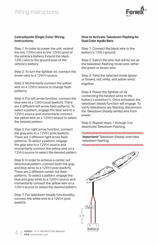
Step 1: In order to power the unit, extend the red, 12V(+) wire to the 12V(+) post of the vehicle’s battery. Extend the black 12V(-) wire to the ground post of the vehicle’s battery.
Step 2: To turn the lightbar on, connect the brown wire to a 12V(+) source.
Step 3: Momentarily connect the yellow wire on a 12V(+) source to change flash patterns.
Step 4: For left arrow function, connect the blue wire to a 12V(+) post (switch). There are 2 different left arrow flash patterns. To select a pattern, engage the blue wire to a 12V(+) source and momentarily connect the yellow wire on a 12V(+) source to select the desired pattern.
Step 5: For right arrow function, connect the gray wire to a 12V(+) post (switch). There are 2 different right arrow flash patterns. To select a pattern, engage the gray wire to a 12V(+) source and momentarily connect the yellow wire on a 12V(+) source to select the desired pattern.
Step 6: In order to achieve a center out directional pattern, connect both the gray and blue wires to a 12V(+) post (switch). There are 2 different center out flash patterns. To select a pattern, engage the blue and gray wires to a 12V(+) source and momentarily connect the yellow wire on a 12V(+) source to select the desired pattern.
Step 7: For takedown steady functionality, connect the white wire to a 12V(+) post (switch).
How to Activate Takedown Flashing for Dual Color Apollo Bars:
Step 1: Connect the black wire to the battery’s 12V(-) ground.
Step 2: Select the wire that will be set as the takedown flashing mode wire, either the green or brown wire.
Step 3: Twist the selected mode (green or brown), red, white, and yellow wires together.
Step 4: Power the lightbar on by connecting the twisted wires to the battery’s positive (+). Once activated, the takedown steady function will engage. To verify takedowns are flashing, disconnect the Takedown Steady (white) wire from power.
Step 5: Repeat steps 1 through 3 to deactivate Takedown Flashing.
+ - battery
fuse
> 1’
Important! Takedown Steady overrides takedown flashing.
V2.0
TM
FENIE X . 2016 INSTRUCTION MANUALWEB. w w w.feniex.com5
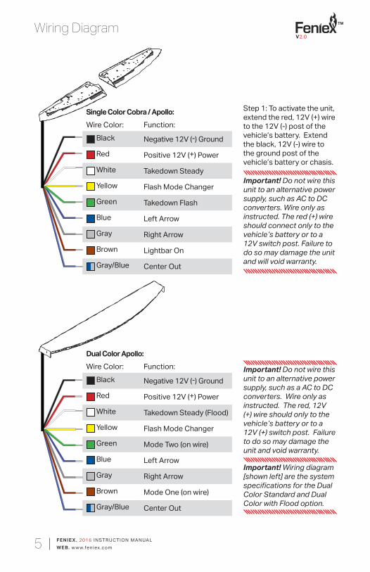
Step 1: To activate the unit, extend the red, 12V (+) wire to the 12V (-) post of the vehicle’s battery. Extend the black, 12V (-) wire to the ground post of the vehicle’s battery or chasis.
Wiring Diagram
Important! Do not wire this unit to an alternative power supply, such as a AC to DC converters. Wire only as instructed. The red, 12V (+) wire should only to the vehicle’s battery or to a 12V (+) switch post. Failure to do so may damage the unit and void warranty.
Single Color Cobra / Apollo:Wire Color: Function:
Black Negative 12V (-) Ground
Red Positive 12V (+) Power
White Takedown Steady
Yellow Flash Mode Changer
Green Takedown Flash
Blue Left Arrow
Gray Right Arrow
Brown Lightbar On
Gray/Blue Center Out
Dual Color Apollo:Wire Color: Function:
Black Negative 12V (-) Ground
Red Positive 12V (+) Power
White Takedown Steady (Flood)
Yellow Flash Mode Changer
Green Mode Two (on wire)
Blue Left Arrow
Gray Right Arrow
Brown Mode One (on wire)
Gray/Blue Center Out
Important! Do not wire this unit to an alternative power supply, such as AC to DC converters. Wire only as instructed. The red (+) wire should connect only to the vehicle’s battery or to a 12V switch post. Failure to do so may damage the unit and will void warranty.
Important! Wiring diagram [shown left] are the system specifications for the Dual Color Standard and Dual Color with Flood option.
V2.0
TM
FENIE X . 2016 INSTRUCTION MANUALWEB. w w w.feniex.com6
Replacing Cobra modules
1
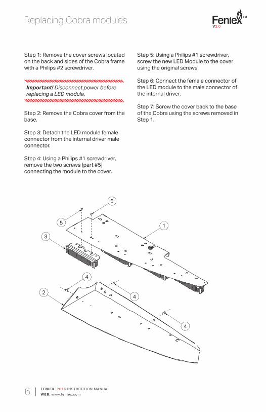
Step 1: Remove the cover screws located on the back and sides of the Cobra frame with a Philips #2 screwdriver.
Step 2: Remove the Cobra cover from the base.
Step 3: Detach the LED module female connector from the internal driver male connector.
Step 4: Using a Philips #1 screwdriver, remove the two screws [part #5] connecting the module to the cover.
Step 5: Using a Philips #1 screwdriver, screw the new LED Module to the cover using the original screws.
Step 6: Connect the female connector of the LED module to the male connector of the internal driver.
Step 7: Screw the cover back to the base of the Cobra using the screws removed in Step 1.
4
2
5
3
4
4
5
Important! Disconnect power before replacing a LED module.
V2.0
TM
FENIE X . 2016 INSTRUCTION MANUALWEB. w w w.feniex.com7
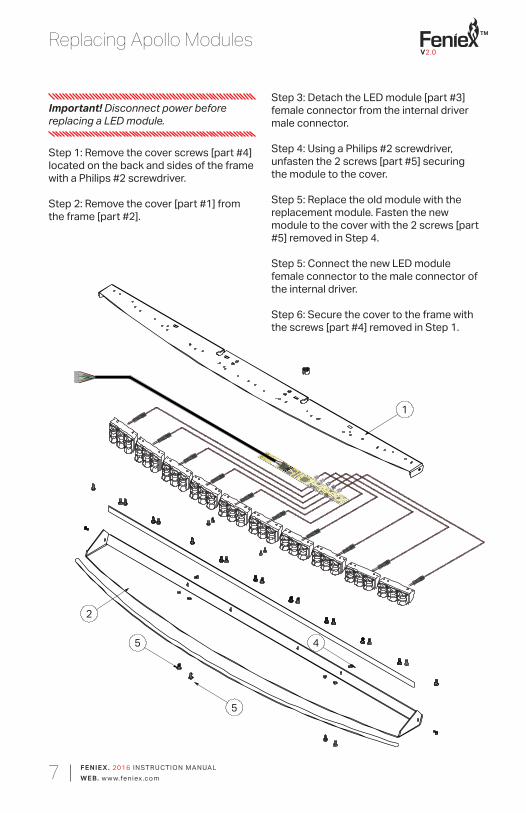
Replacing Apollo Modules
Step 3: Detach the LED module [part #3] female connector from the internal driver male connector.
Step 4: Using a Philips #2 screwdriver, unfasten the 2 screws [part #5] securing the module to the cover.
Step 5: Replace the old module with the replacement module. Fasten the new module to the cover with the 2 screws [part #5] removed in Step 4.
Step 5: Connect the new LED module female connector to the male connector of the internal driver.
Step 6: Secure the cover to the frame with the screws [part #4] removed in Step 1.
Important! Disconnect power before replacing a LED module.
1
5
2
5 4
Step 1: Remove the cover screws [part #4] located on the back and sides of the frame with a Philips #2 screwdriver.
Step 2: Remove the cover [part #1] from the frame [part #2].
V2.0
TM
FENIE X . 2016 INSTRUCTION MANUALWEB. w w w.feniex.com8
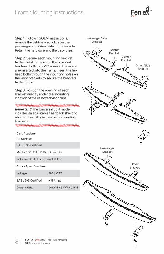
Front Mounting Instructions
Step 1: Following OEM instructions, remove the vehicle visor clips on the passenger and driver side of the vehicle. Retain the hardware and the visor clips.
Step 2: Secure each mounting bracket to the metal frame using the provided hex head bolts or 8-32 screws. These are pre-inserted into the frame. Insert the hex head bolts through the mounting holes on the visor brackets to secure the brackets to the frame.
Step 3: Position the opening of each bracket directly under the mounting location of the removed visor clips.
Certifi cations:
CE Certifi ed
SAE J595 Certifi ed
Meets CCR, Title 13 Requirements
RoHs and REACH compliant LEDs
Cobra Specifi cations
Voltage: 9-13 VDC
SAE J595 Certifi ed < 5 Amps
Dimensions: 0.93″H x 37″W x 5.5″H
Important! The Universal Split model includes an adjustable fl ashback shield to allow for fl exibility in the use of mounting brackets.
Passenger Side Bracket
CenterBracket
CenterBracket
Driver Side Bracket
PassengerBracket
DriverBracket
V2.0
TM
FENIE X . 2016 INSTRUCTION MANUALWEB. w w w.feniex.com9
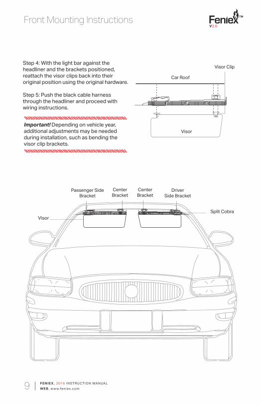
Front Mounting Instructions
Passenger Side Bracket
DriverSide Bracket
CenterBracket
CenterBracket
VisorSplit Cobra
Step 4: With the light bar against the headliner and the brackets positioned, reattach the visor clips back into their original position using the original hardware.
Step 5: Push the black cable harness through the headliner and proceed with wiring instructions.
Visor
Car Roof
Visor Clip
Important! Depending on vehicle year, additional adjustments may be needed during installation, such as bending the visor clip brackets.
V2.0
TM
FENIE X . 2016 INSTRUCTION MANUALWEB. w w w.feniex.com10
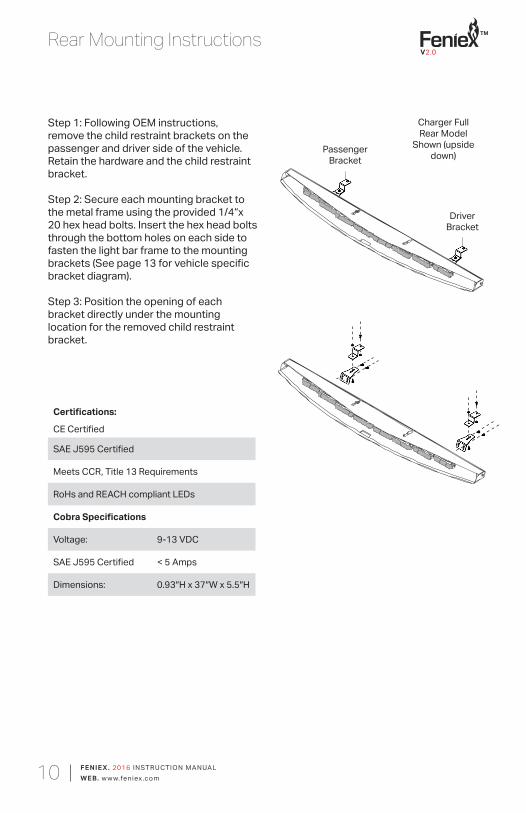
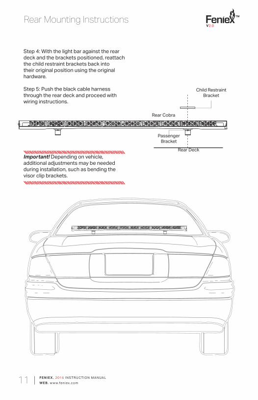
Rear Mounting Instructions
Step 1: Following OEM instructions, remove the child restraint brackets on the passenger and driver side of the vehicle. Retain the hardware and the child restraint bracket.
Step 2: Secure each mounting bracket to the metal frame using the provided 1/4“x 20 hex head bolts. Insert the hex head bolts through the bottom holes on each side to fasten the light bar frame to the mounting brackets (See page 13 for vehicle specific bracket diagram). Step 3: Position the opening of each bracket directly under the mounting location for the removed child restraint bracket.
Certifications:
CE Certified
SAE J595 Certified
Meets CCR, Title 13 Requirements
RoHs and REACH compliant LEDs
Cobra Specifications
Voltage: 9-13 VDC
SAE J595 Certified < 5 Amps
Dimensions: 0.93″H x 37″W x 5.5″H
Charger Full Rear Model
Shown (upside down)Passenger
Bracket
DriverBracket
V2.0
TM
FENIE X . 2016 INSTRUCTION MANUALWEB. w w w.feniex.com11
Rear Mounting Instructions
Important! Depending on vehicle, additional adjustments may be needed during installation, such as bending the visor clip brackets.
Rear Deck
Child Restraint Bracket
PassengerBracket
Rear Cobra
Step 4: With the light bar against the rear deck and the brackets positioned, reattach the child restraint brackets back into their original position using the original hardware.
Step 5: Push the black cable harness through the rear deck and proceed with wiring instructions.
V2.0
TM
FENIE X . 2016 INSTRUCTION MANUALWEB. w w w.feniex.com12
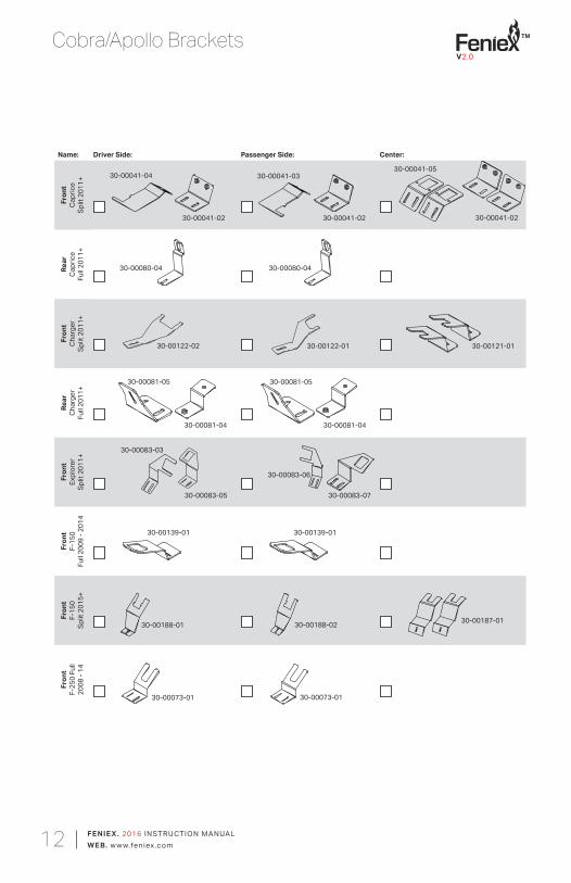
Cobra/Apollo Brackets
Name: Driver Side: Passenger Side: Center:
Fron
tCa
pric
eSp
lit 2
011+
Rear
Capr
ice
Full 2
011+
Fron
tCh
arge
rSp
lit 2
011+
Rear
Char
ger
Full 2
011+
Fron
tEx
plor
erSp
lit 2
011+
Fron
tF-
150
Full 2
009
- 201
4
Fron
tF-
150
Split
201
5+
Fron
tF-
250
Full
2008
- 14
30-00041-04
30-00041-02
30-00041-03
30-00041-02
30-00041-05
30-00041-02
30-00080-04 30-00080-04
30-00122-02 30-00122-01 30-00121-01
30-00081-05
30-00081-04
30-00081-05
30-00081-04
30-00083-03
30-00083-05
30-00083-06
30-00083-07
30-00139-01 30-00139-01
30-00073-01 30-00073-01
30-00188-01 30-00188-02 30-00187-01
V2.0
TM
FENIE X . 2016 INSTRUCTION MANUALWEB. w w w.feniex.com13
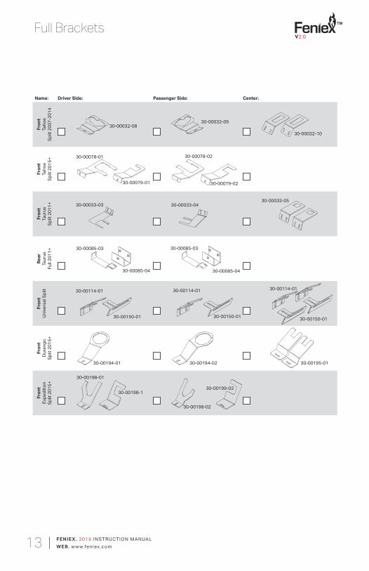
Full Brackets
Name: Driver Side: Passenger Side: Center:
Fron
tTa
hoe
Split
200
7-20
14
Fron
tTa
hoe
Split
201
5+
Fron
tTa
urus
Split
201
1+
Rear
Taur
us
Full 2
011+
Fron
tUn
iver
sal S
plit
Fron
tD
uran
go
Split
201
5+
Fron
tEx
pedi
tion
Split
201
5+
30-00032-0830-00032-09
30-00032-10
30-00078-01
30-00079-01
30-00078-02
30-00079-02
30-00033-03 30-00033-0430-00033-05
30-00085-03
30-00085-04
30-00085-03
30-00085-04
30-00114-01
30-00150-01
30-00114-01
30-00150-01 30-00150-01
30-00114-01
30-00194-01
30-00198-1
30-00195-01
30-00198-02
30-00198-01
30-00194-02
30-00199-02
V2.0
TM
FENIE X . 2016 INSTRUCTION MANUALWEB. w w w.feniex.com14
FAQ
How do I reduce the flashback from the interior lightbar?
A thick rubber gasket is attached to the base of the lightbar. Connect the rubber gasket trim to the base. Extra length is provided to allow for flexibility in adjustment. Cut off excess trim. The thin gasket connects to the top of the base, while the thicker gasket connects to the bottom.
How do I change out a module on the Innerbar?
Reference page 6 to replace a Cobra LED module. To replace an Apollo LED module, reference page 7.
Can I program takedowns for Cobra or Apollo single models?
For takedown steady functionality flood wiring, connect the white wire to a 12V(+) post (switch) or engage the green wire to a 12V(+) post for takedown flashing (only if takedowns are in the unit). Takedown steady overrides takedown flashing.
Can I program takedowns for Apollo Dual Models?
Important Note! Takedown steady overrides takedown flashing
Activate takedown Flashing for Dual Color:
Step 1: Connect the black wire to the battery’s 12V(-) ground.
Step 2:Select the wire that will be set as the takedown flashing mode wire, either the green or the brown wire.
Step 3: Twist the selected mode (green or brown), red, white and yellow wires together.
Step 4: Power the lightbar on by connecting the twisted wires to the battery’s positive (+). Once activated, the takedown steady function will engage. To verify takedowns are flashing, disconnect takedown steady (white) wire from power.
Step 5: Repeat steps 1 through 3 to deactivate takedown flashing.
V2.0
TM
FENIE X . 2016 INSTRUCTION MANUALWEB. w w w.feniex.com15
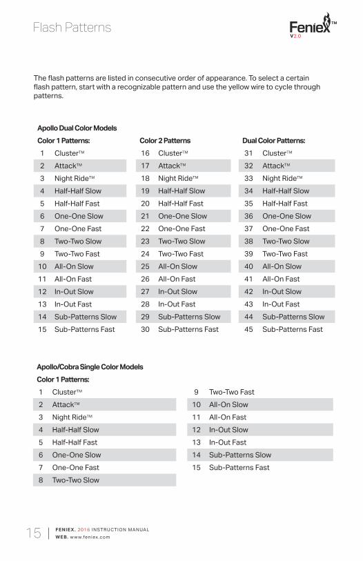
Flash Patterns
Apollo Dual Color ModelsColor 1 Patterns:1 ClusterTM
2 AttackTM
3 Night RideTM
4 Half-Half Slow5 Half-Half Fast6 One-One Slow7 One-One Fast8 Two-Two Slow9 Two-Two Fast
10 All-On Slow11 All-On Fast12 In-Out Slow13 In-Out Fast14 Sub-Patterns Slow15 Sub-Patterns Fast
The flash patterns are listed in consecutive order of appearance. To select a certain flash pattern, start with a recognizable pattern and use the yellow wire to cycle through patterns.
Color 2 Patterns16 ClusterTM
17 AttackTM
18 Night RideTM
19 Half-Half Slow20 Half-Half Fast21 One-One Slow22 One-One Fast23 Two-Two Slow24 Two-Two Fast25 All-On Slow26 All-On Fast27 In-Out Slow28 In-Out Fast29 Sub-Patterns Slow30 Sub-Patterns Fast
Dual Color Patterns:31 ClusterTM
32 AttackTM
33 Night RideTM
34 Half-Half Slow35 Half-Half Fast36 One-One Slow37 One-One Fast38 Two-Two Slow39 Two-Two Fast40 All-On Slow41 All-On Fast42 In-Out Slow43 In-Out Fast44 Sub-Patterns Slow45 Sub-Patterns Fast
Apollo/Cobra Single Color ModelsColor 1 Patterns:1 ClusterTM
2 AttackTM
3 Night RideTM
4 Half-Half Slow5 Half-Half Fast6 One-One Slow7 One-One Fast8 Two-Two Slow
9 Two-Two Fast10 All-On Slow11 All-On Fast12 In-Out Slow13 In-Out Fast14 Sub-Patterns Slow15 Sub-Patterns Fast


![Apollo cobra innerbar - SIRENNETsirennet.com/pdf/Apollo-Cobra-Innerbar_install.pdf · Apollo cobra innerbar V1.1. V1.1 TM ... Wiring diagram [shown left] are the system ... Split](https://static.fdocuments.net/doc/165x107/5aeb805e7f8b9a585f8dafce/apollo-cobra-innerbar-cobra-innerbar-v11-v11-tm-wiring-diagram-shown-left.jpg)