Apollo 9000 - Analytical Instrument Management Manual_vD.pdf · 2016-06-13 · 1–4. INTRODUCTION....
157
Apollo 9000 TOC Combustion Analyzer User Manual
Transcript of Apollo 9000 - Analytical Instrument Management Manual_vD.pdf · 2016-06-13 · 1–4. INTRODUCTION....

Apollo 9000TOC Combustion Analyzer
User Manual

Mason, Ohio USA
www .teledynetekmar.com
Document Part Number: 14-9000-074_vD
Rev. D • Version 08-09-03
Copyright
© 2003 Teledyne Tekmar Co.
No part of this document may be copied, reproduced, transmitted in any form orby any means, electronic or mechanical, including photocopying, recording, orinformation storage and retrieval systems, for any purpose other than thepurchaser’s personal use, without the express written permission of TekmarCompany.
Updates
Teledyne Tekmar may update the information contained in this documentwithout notice to the purchaser.
The following are registered items:
Adobe Acrobat® is a registered trademark of Adobe Systems Incorporated.
Intel® Pentium® is a registered trademark of Intel.
Microsoft Windows®, Windows NT®, Microsoft® Internet Explorer and Microsoft®
Excel are either registered trademarks or trademarks of Microsoft Corporation inthe United States and/or other countries.
Pyrex® is a registered trademark of Corning Incorporated.
Swagelok® is a registered trademark of Swagelok Companies.
TEFLON® is a registered trademark of E.I. du Pont de Nemours & Co., Inc.
Tygon® is a registered trademark of Norton Company.
Whatman® TOC Gas Generator is a registered trademark of Whatman, Inc.
(800) 543-4461
Outside the U.S. and Canada:(513) 229-7000
Service (800) 874-2004
Fax (513) 229-7050
WebbG
Teledyne Tekmar

USER MANUAL

TABLE OF CONTENTS

iii
TABLE OF CONTENTS
INTRODUCTION
1.1 Apollo 9000 TOC Analyzer 1-3
1.2 Technical Specifications 1-4
1.3 Safety 1-8
1.4 Part Descriptions 1-9
1.5 Apollo 9000 OperatingModes 1-15
1.6 Sample Introduction 1-15
1.7 Prime Replicate 1-16
1.8 Analysis Process 1-16
SYSTEM SETUP
2.1 Before You Begin 2-3
2.2 Unpack and Inspect 2-6
2.3 Tools and Supplies Needed forConnections 2-7
2.4 Pneumatic Connections 2-7
2.5 Electrical Connections 2-11
2.6 Install the Autosampler(Optional) 2-12
2.7 Add Catalyst to and Installthe Combustion Tube 2-18
2.8 Install TOC Talk Software 2-21
2.9 Condition CombustionTube Catalyst 2-22
2.10 Cleaning Procedure forConditioned Catalyst 2-23
TOC TALK
3.1 TOC Talk Control Screen 3-3
3.2 Instrument Setup 3-3
3.3 Instrument Diagnostics 3-6
3.4 Archive Data 3-10
3.5 Password Setup 3-11
3.6 Wakeup Schedule 3-12
CALIBRATION
4.1 System Calibration 4-3
4.2 Standard CalibrationWithout Autosampler Tutorial 4-4
4.3 Standard CalibrationWith Autosampler Tutorial 4-11
SAMPLE ANALYSIS
5.1 Sample Analysis 5-3
5.2 Tutorial:TOC Results Made EasyWithout Autosampler 5-3
5.3 Tutorial:TOC Results Made EasyWith Autosampler 5-6
5.4 Sample Blanks 5-9
SPECIAL APPLICATIONS
6.1 Sample Preservationfor TOC 6-3
6.2 Applications 6-4
6.3 Modifying Analysis Methods 6-8
MAINTENANCE ANDTROUBLESHOOTING
7.1 Scheduled MaintenanceChecks 7-3
7.2 Replacing Parts 7-4
7.3 TroubleshootingApollo 9000 7-22
7.4 Teledyne TekmarCustomer Support 7-29
CALIBRATION STANDARD
8.1 CalibrationStandard Preparation 8-3
8.2 Procedure forMaking Standards 8-3
DIAGRAMS
APPENDIX A
INDEX

INTRODUCTION
1

1–3
INTRODUCTION
1.1 Apollo 9000 TOCAnalyzer
Apollo 9000 is comprised of thefollowing:
• Syringe - for sample and reagentintroduction
• Sparger - for inorganic analysis andsample preparation for TOCanalysis
• Combustion Furnace
• Furnace Injection Port
• Water Trap - for moisture removal
• Permeation Tube - for moistureremoval
• Corrosives Scrubber - for halogenremoval
• NDIR Detector - for carbon dioxidedetection
TOC Analysis Overview
Total organic carbon (TOC) analysisgrew from the need to analyze wastewater and municipal water for organicmatter. The need to protect it andestablish criteria for screening andmeasuring contaminant levels wasrecognized when Congress enacted theResource Conservation and RecoveryAct (RCRA) in 1976. This act requiresoperators of waste disposal sites tomonitor their groundwater on aquarterly basis for organic carbon levelsand organic halide levels.
TOC analyzers are also widely used inmonitoring the quality of process waterin the semiconductor andpharmaceutical industries. Becauseorganic material can causecontamination, TOC analysis is alsoperformed to protect processequipment such as boilers, turbines,and purification devices. Furthermore,TOC levels in solids such as soils, claysand sediments are of increasinginterest.
TOC analyzers can measure totalcarbon (TC), total organic carbon (TOC),inorganic carbon (IC), purgeableorganic carbon (POC), andnonpurgeable organic carbon (NPOC).If the POC is <1% of the TOC, thenNPOC is equivalent to TOC.
TOC measurement involves:
1. Oxidizing organic carbon in asample.
2. Detecting and quantifying theoxidized product (CO
2).
3. Presenting the result in units ofmass of carbon per volume ofsample (liquids) or per mass ofsolid (solids).
Figure 1-1 Apollo 9000

1–4
INTRODUCTION
User Interface
TOC Talk, the Apollo 9000 software,effortlessly monitors and performscalculations in a Windows 95/98/NTplatform.
The following are some of the featuresof Apollo 9000 software, TOC Talk:
• Pre-defined Default Methods
• Multi-Point Calibration
• Outlier Deletion
• Wake-up and Shut-down
• Plotted Calibration Curve andStatistics
• Multiple Method Storage
• Analog Display of Peaks
• Continuous Scrolling of Results
• Diagnostics
1.2 Technical Specifications
Apollo 9000 TOC Analyzer
Chemistry:
• Oxidation by Combustion(from 680°C to 1000°C)
• IC by Acidification and Sparge
Detector:
• Nondispersive Infrared (NDIR)
Measurements:
• TOC (NPOC), TC-IC, TC, IC
Analytical:
• Range:
4 ppbC to 25,000 ppmC (samplevolume, detector, and dilutiondependent) using only 4 selectableanalytical ranges
Precision:
• Typical 0.05% of full scale or
• RSD +/- 3%, whichever is greater,over 3 replicates
Injection Volume:
• Up to 2 ml
Analysis Time:
• 1 to 3 minutes, typical
Detection and Results
Carbon in the sample is first convertedto CO
2 by the combustion furnace for
TOC and TC analysis or by the IC spargerfor IC analysis. A carrier gas thensweeps the derived CO
2 through a
nondispersive infrared (NDIR) detector.Sensitive to the absorbtion frequencyof CO
2, the NDIR generates a non-linear
signal that is proportional to theinstantaneous concentration of CO
2 in
the carrier gas. That signal is thenlinearized and integrated over thesample analysis time. The resulting areais then compared to stored calibrationdata and a sample concentration inparts-per-million (ppm) is calculated.

1–5
INTRODUCTION
TOC Analysis Time:
• 15 minutes per triplicate, typical
Liquid Handling:
• Syringe driver, 8-port valve
• Auto-dilution method providedfrom 4000 ppmC to 25,000 ppmCand/or difficult matrices
• Auto-rinsing with sample and rinsewater
Sample Introduction:
• Automatic syringe injection
• Autosampler
• Solids Boat
• Manual Syringe
Controller:
• PC, Interface through Windows (95,98 or NT), Password Protected
Data Handling:
• Automatic and customizedSpreadsheet reports transferable toMicrosoft Excel
• Real-time display of NDIR signal
• Outlier deletion
• Recalculations with differentcalibration curves
• Recalculations with different blankvalues
Calibration:
• Multi-point and automatic blanksubtraction
Other Features and Options:
• Preprogrammed point-and-clickmethod setup
• Programmable automatic Wake-up
• Automatic shutdown/standby
• Selectable IC sparge methods
• Automatic file management
• Flow rate monitoring
• Priority samples via scheduledinterrupt
• Online help
• Solids module
• Near line monitoring
• Exceeds ISO 8245 particulaterequirements with optional kit
• Stirring option
• Automatic blanking or manualentry of blank value
Typical Methods and PrincipalApplications:
• EPA 415.1 and 9060A
• Standard Method 5310B
• ASTM D2579
• ISO (Draft) 8245
• AOAC 973.47
• Cleaning Validation
• USP 643
• Drinking / Surface water
• Industrial Waste Effluent
• Waste water
• Sea Water

1–6
INTRODUCTION
STS 8000 Autosampler
Sampler Changer Type:
• XYZ robot with stationary rackdesign
Positioning Performance:
• Accuracy +/-1mm in XYZdimensions
• Repeatability +\-0.25 mm in XYZdimensions
Septum Piercing:
• Available with septum piercing kit.Has vertical punch strength of 3.8kg (8.38 lbs.).
Rinsing:
• Auto-rinsing with sample and/orrinse water via built-in rinse station
Rack Selection:
• (2) 77 position trays for 25mlculture tubes (18 x 150 mm)
• (2) 35 position trays for 40ml VOAvials (28 X 95 mm)
Dimensions:
• cm 53.5 W x 43.7 D x 37.1 H
• in 21.1 W x 17.2 D x 14.6 H
• 17.7 kg (39 lbs)
Certification:
• UL, CSA, and CE
• EMC EN 50081-1 and EN 50082-1
Utility Requirements:
• Power Entry Module:
2IEC 5 x 20 mm fuses
• 100v OperationT10A, 250v, fast blow
• 115v OperationT10A, 250v, fast blow
• 230v OperationT5A, 250v, fast blow
• Voltage:100/120/230 VAC (±10%)
• Frequency:50/60 Hz (excluding NDIR)
• Power:1200 VA
Dimensions (Approximate):
• cm 40 W x 61 D x 53 H
• in 16" W x 23" D x 21" H
• 50 kg ( 110 lb.) shipping weight
Gas Supply:
• Hydrocarbon and CO2-free air
• Balston / Whatman TOC GasGenerator
Gas Pressure:
• 30 to 35 psi (206.7 to 241.2 kPa)

1–7
INTRODUCTION
Electrical:
• Voltage:100/120/230 VAC (±10%)
• Frequency:50/60 Hz
• Power:200VA
Certification:
• UL, CSA, and CE
• EMC EN50081-1 andEN 50082-1
1–8
INTRODUCTION
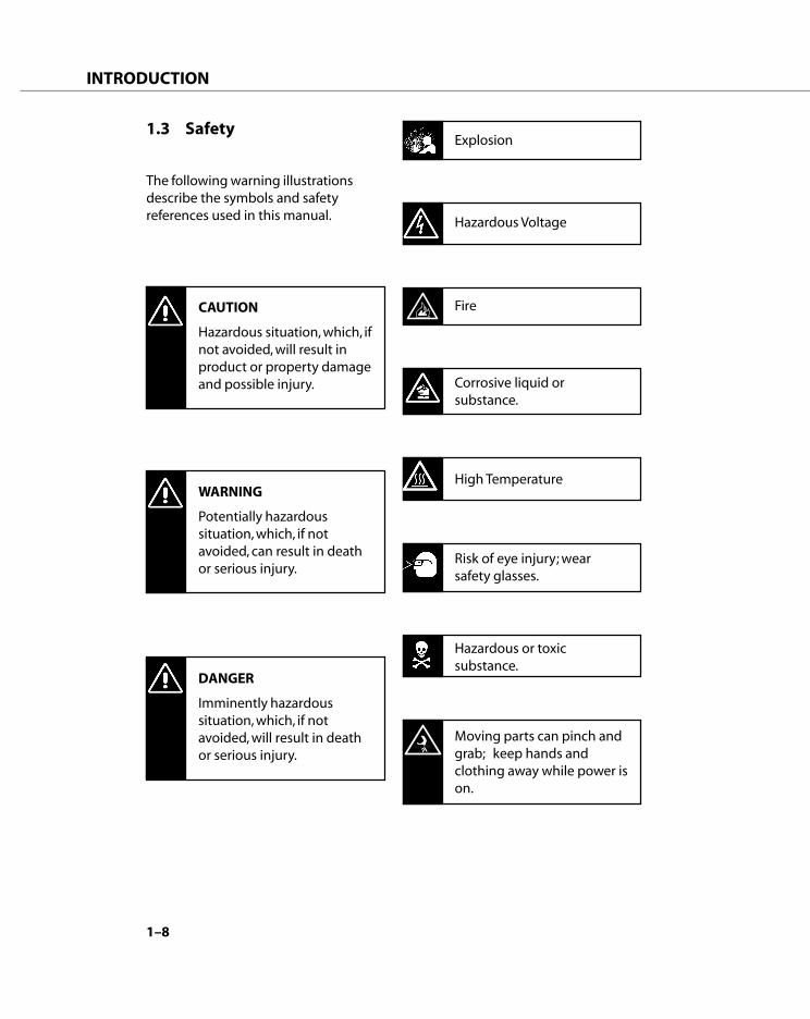
1.3 Safety
The following warning illustrationsdescribe the symbols and safetyreferences used in this manual.
CAUTION
Hazardous situation, which, ifnot avoided, will result inproduct or property damageand possible injury.
WARNING
Potentially hazardoussituation, which, if notavoided, can result in deathor serious injury.
DANGER
Imminently hazardoussituation, which, if notavoided, will result in deathor serious injury.
Explosion
Hazardous Voltage
Fire
Corrosive liquid orsubstance.
High Temperature
Risk of eye injury; wearsafety glasses.
Hazardous or toxicsubstance.
Moving parts can pinch andgrab; keep hands andclothing away while power ison.

1–9
INTRODUCTION
1.4 Part Descriptions
Figure 1.4.1 Apollo 9000, Front
Figure 1.4.2 Apollo 9000, Rear
Cooling Fan
Carrier Gas Inlet
Waste Outlet
Permeation Dryer, ICSparger Valve, and NDIRGas Outlet
I/O Ports
Power Switch
Syringe Driver and 8-port Valve
The syringe driver is a precisionmeasuring instrument that aspiratesand dispenses fluid. The syringe drivercontains electronics, a syringe, 8-portTeflon valve, and stepper motors. Theelectronics control the motors andcommunication between the syringedriver and microcontroller.
The syringe driver can dispense up to2.5 ml (± .1%) of sample or reagent.
The syringe driver turns an 8-portTeflon valve. Each port on the valve isfitted with a valve washer beforeinsertion of relevant tubing fitting toensure an airtight seal. The portassignments for this valve are asfollows:
Figure 1.4.3 Syringe Driver
Figure 1.4.4 8-Port Valve

1–10
INTRODUCTION
IC Sparger
The sparger is a glass vessel that holdsthe sample while Apollo 9000:
• acidifies and sparges the sample ofinorganic carbon (IC) andpurgeable organic carbon (POC),and prepares the sample for TOCanalysis.
• provides the location for Range 4sample dilution
Figure 1.4.5 IC Sparger
Gas flows through the sparger,removing the IC from the sample. TheApollo 9000 can detect IC in IC mode orsend it to vent while preparing for TOCmode.
Combustion Furnace withInjection Port
The combustion furnace provides thehigh temperature necessary to oxidizethe carbon in the sample to CO
2. It
holds the quartz combustion tubebetween the bottom connector and theinjection port at the top. O-ringsprovide gas-tight seals at each end. Thecombustion tube contains a bed ofproprietary catalyst that promotesoxidation of organics.
Figure 1.4.6Combustion Furnace with Injection Port
The injection port provides theinterface for the sample line and thefurnace carrier gas into the combustionfurnace. The sample line enters fromthe top of the injection port and thecarrier gas enters from the right of theinjection port.

1–11
INTRODUCTION
Corrosives Scrubber
The detector, which measures carbondioxide, can be damaged by halogen. Toprevent analytical errors, the corrosivesscrubber removes halogens from thecarbon dioxide before it enters thedetector. The corrosives scrubber is aglass tube filled with Pyrex wool and tinand copper granules.
Moisture Control System
Moisture is removed from the gasgoing to the detector to preventcondensation in the detector.
The Apollo 9000 moisture controlsystem consists of a condensor coil,cooling fan, water trap, and permeationdryer.
The combustion furnace (where carbonin the sample is converted to carbondioxide) generates high heat. Carriergas sweeps CO
2 and water vapor out of
the combustion furnace. The samplethen travels through tubing, cooled bya fan to condense water vapor.
Figure 1.4.8 Cooling Fan
Figure 1.4.7 Corrosives Scrubber
PyrexWool
Sn Cu
PyrexWool

1–12
INTRODUCTION
Next, the carbon dioxide travelsthrough the water trap, where water iscollected.
Then the carbon dioxide passesthrough a semi-permiable Nafion® tubeto further remove moisture. This tube issealed into an impermeable shell,which has openings adjacent to thesample inlet and outlet. When a wet gasstream flows through the tube and acountercurrent dry gas stream purgesthe shell, water molecules diffusethrough the walls of the tubing.
Figure 1.4.10 Permeation Tube
Nondispersive Infrared Detector
Apollo 9000 converts carbon in thesample to carbon dioxide. Thenondispersive (single beam) infrareddetector uses electromagnetic radia-tion or infrared energy to measure thiscarbon dioxide. This measurement isproportional to the carbon in thesample.Inside the detector, a beam of infraredenergy is directed through a samplecell to the detecting apparatus. Thisapparatus consists of two chambers,which are filled with CO
2 and con-
nected by a flow-sensing device. Theunobstructed infrared energy absorbedby this CO
2 causes the pressure to
increase in the forward chamber andequilibrate between the two chambers.When CO
2 is then introduced to the
sample cell, some of the infrared energyis absorbed. Therefore the pressure inthe forward chamber decreases andCO
2 flows to equilibrate the pressure.
This flow causes a voltage output fromthe flow-sensor, which is proportionalto the concentration of CO
2 in the
sample cell.
Figure 1.4.11Nondispersive Infrared Detector (NDIR)
Figure 1.4.9 Water Trap
to PermeationDryer
In
to 8-port
Purge Gas Out
Purge Gas In
SampleGas In

1–13
INTRODUCTION
Flow Restrictors
Five flow restrictors maintain the flowrate of the supply gas as follows:1. 200 ml/min to the combustion
furnace2. 200 ml/min to the IC sparger3. 200 ml/min to the autosampler
sparge line4. 200 ml/min to the permeation tube5. 50 ml/min to purge the NDIR
Figure 1.4.12 Flow Restrictor
When you turn off the gas(valve 1), 50 ml/min of carriergas continues to purge theNDIR.
Temperature Controller
The set point for the combustionfurnace is controlled by a temperaturecontroller found on the front face of theApollo 9000 instrument just below thesyringe driver. The temperature con-troller LED displays the actual tempera-ture of the combustion furnace. Theblue button (Set) displays the set pointfor the combustion furnace whenpressed. By holding down the Setbutton and pressing the appropriategray Up and Down buttons, the setpoint for the combustion furnace canbe adjusted as needed.
Figure 1.4.13 Temperature Controller

1–14
INTRODUCTION
Optional STS 8000 Autosampler
The optional autosampler is an XYZrobot that automates sample handlingprocedures. It allows the user toincrease throughput and operate theanalyzer unattended for many hours.
The autosampler tray holds 2 racks;each rack can hold up to 77 (25ml)culture tubes or 35 (40ml) VOA vials.Vials may be fitted with pierceableTeflon-backed septum caps.
The autosampler rinses the inside andoutside of the needle via a dedicatedrinse station.
Figure 1.4.14 Optional STS 8000 Autosampler
Optional 183 Boat Sampler
The 183 Boat Sampler is ideal for soils,sediments, sludges and particle-ladenliquids.
Syringeable samples are injecteddirectly into the platinum sample boatthrough a septum, minimizing contami-nation of the combustion stream byambient air. Solid samples are weighedinto the removable boat, which isreadily accessible through the hatch-covered port. The boat is manuallyadvanced into the furnace, where thesample is combusted at 800°C.
Total Carbon (TC) is measured by directinjection of sample without pretreat-ment. Total Organic Carbon (TOC) ismeasured by sparging off the InorganicCarbon (IC) from the acidified samplebefore injection, using the spargingstation built into the instrument. IC ismeasured by injecting the watersample into a special vessel containingacidified water: the CO
2 produced is
swept to the detector and measured.

1–15
INTRODUCTION
1.5 Apollo 9000 OperatingModes
Apollo 9000 has four operatingmodes—Total Organic Carbon (TOC),Total Carbon (TC), Inorganic Carbon (IC),and Total Carbon Minus InorganicCarbon (TC-IC).
1.5.1 Total Carbon (TC)
TC is the measurement of all the carbonin the sample, both organic and inor-ganic, as a single parameter.
1.5.2 Inorganic Carbon (IC)
Inorganic carbon consists of carbonatesand bicarbonates in samples. IC isanalyzed in liquid samples by acidifyingwith an inorganic acid to pH 3 or lowerand sparging with an inert gas.
1.5.3 Total Organic Carbon (TOC)
TOC analysis consists of addition of acidand sparging with an inert gas toremove IC. The remaining carbon iscalled TOC (if purgeables are less than1% of the organic carbon).
1.5.4 TC-IC
TC-IC (also called TOC by difference)requires a separate analysis for TC thenIC. If present, purgeable organic carbon(POC) will be included in the TC mea-surement.
1.6 Sample Introduction
Before introducing a sample, Apollo9000 automatically rinses the syringe toeliminate any contaminants that mayinterfere with the testing process. Thisrinsing occurs through a loop sequencewhere the syringe is filled and dis-carded with DI water.
Because air bubbles in the syringe canaffect test results, Apollo 9000 auto-matically discards sample from the topand bottom portion of the sample(regardless of your sample size).
Figure 1.5.1 Syringe Drive Sample Delivery
1234567123456712345671234567
12345123451234512345
200 µl to Waste
Deliver 1 ml Sample
50 µl to Waste
1–16
INTRODUCTION
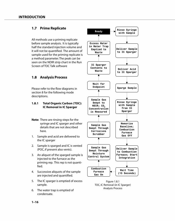
Figure 1.8.1TOC, IC Removal (in IC Sparger)
Analysis Process
Ready Rinse Syringewith Sample
Deliver Sampleto IC Sparger
Deliver Acidto IC Sparger
Sparge Sample
Deliver Sampleto CombustionFurnace; StartIntegration
CombustionFurnaceGas On
Wait forEndpoint
Wait Time(15 Seconds)
IC SpargerContents to
Waste
Rinse Syringewith Sample
from ICSparger
MemorizeBaseline;CombustionFurnaceGas Off
Sample GasSwept Through
MoistureControl System
Sample GasSwept ThroughCorrosivesScrubber
Sample GasSwept toNDIR; CO2
Concentrationis Measured
Excess Waterin Water TrapEmptied to
Waste
1.7 Prime Replicate
All methods use a priming replicatebefore sample analysis. It is typicallyhalf the standard injection volume andit will not be quantified. The amount ofsample used for the priming replicate isa method parameter. The peak can beseen on the NDIR strip chart in the RunScreen of TOC Talk software
1.8 Analysis Process
Please refer to the flow diagrams insection 8 for the following modedescriptions.
1.8.1 Total Organic Carbon (TOC):IC Removal in IC Sparger
Note: There are rinsing steps for thesyringe and IC sparger and otherdetails that are not describedhere.
1. Sample and acid are delivered tothe IC sparger
2. Sample is sparged and IC is vented(POC, if present also vents).
3. An aliquot of the sparged sample isinjected to the furnace as thepriming rep. This rep is not quanti-fied.
4. Successive aliquots of the sampleare injected and quantified.
5. The IC sparger is emptied of excesssample.
6. The water trap is emptied ofcondensate.

1–17
INTRODUCTION
1.8.2 Total Organic Carbon (TOC),Removal of IC with ASMSparge
Note: There are rinsing steps for thesyringe and other details thatare not represented here.
1. The Autosampler (ASM) needle isrinsed with DI water and then theneedle and transfer line is emp-tied.
2. The ASM needle goes to the acidvial and the syringe draws theamount of acid that is prescribedby the analysis method.
3. The ASM needle goes to thesample vial delivers the acid andsparge gas is started.
4. After the sparge time is completed,and aliquot of the sparged sampleis injected to the furnace as thepriming rep. This rep is not quanti-fied.
5. Successive aliquots of the sampleare injected and quantified.
6. After the final rep of a vial isinjected, the ASM needle is rinsedwith DI water and then the se-quence begins for the next samplevial.
7. The water trap is emptied ofcondensate.
Figure 1.8.2TOC, IC Removal (with ASM Sparge)
Analysis Process
ReadyDeliverAcid to
Sample Vial
SpargeSample Vial
MemorizeBaseline;CombustionFurnaceGas Off
Deliver Sampleto Combustion
Furnace
NDIR SignalLinearized and
Sent toComputer for
Analysis
Wait Time(15 Seconds)
Sample GasSwept Through
MoistureControl System
Sample GasSwept ThroughCorrosivesScrubber
Sample GasSwept toNDIR; CO2
Concentrationis Measured
Rinse Syringewith Sample
Combustionfurnace gas on
Excess Waterin Water TrapEmptied to
Waste

1–18
INTRODUCTION
Figure 1.8.4 TC Analysis Process
Ready Rinse Syringewith Sample
MemorizeBaseline;CombustionFurnaceGas Off
CombustionFurnaceGas On
Wait Time(15 Seconds)
Sample GasSwept Through
MoistureControl System
Sample GasSwept ThroughCorrosivesScrubber
Sample GasSwept toNDIR; CO2
Concentrationis Measured
Deliver Sampleto CombustionFurnace; StartIntegration
Wait forEndpoint
Excess Waterin Water TrapEmptied to
Waste
1.8.3 Total Carbon MinusInorganic Carbon (TC-IC)
Note: There are rinsing steps for thesyringe and IC sparger and other detailsthat are not represented here.
1. Sample is drawn into the syringe.
2. The priming rep aliquot is injectedinto the furnace. This rep is notquantified.
3. The analysis rep is injected to thefurnace and quantified.
4. Sample, DI water and acid aredelivered to the IC sparger.
5. The sparge gas is turned on andthe IC is quantified.
6. The IC sparger is emptied ofsample.
7. Steps 3 through 6 repeat until allreps are completed.
8. The water trap is emptied ofcondensate.
1.8.4 Total Carbon (TC)
1. Sample is drawn into the syringe.
2. The priming rep aliquot is injectedinto the furnace. This rep is notquantified.
3. Successive analysis reps areinjected into the furnace andquantified.
4. Condensate is removed from thewater trap.
1–19
INTRODUCTION
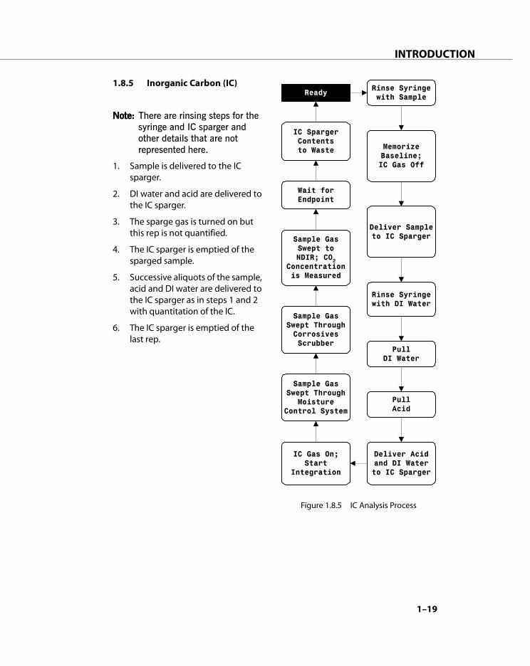
1.8.5 Inorganic Carbon (IC)
Note:Note:Note:Note:Note: There are rinsing steps for thesyringe and IC sparger andother details that are notrepresented here.
1. Sample is delivered to the ICsparger.
2. DI water and acid are delivered tothe IC sparger.
3. The sparge gas is turned on butthis rep is not quantified.
4. The IC sparger is emptied of thesparged sample.
5. Successive aliquots of the sample,acid and DI water are delivered tothe IC sparger as in steps 1 and 2with quantitation of the IC.
6. The IC sparger is emptied of thelast rep.
Figure 1.8.5 IC Analysis Process
Ready Rinse Syringewith Sample
MemorizeBaseline;IC Gas Off
IC SpargerContentsto Waste
IC Gas On;Start
Integration
Sample GasSwept Through
MoistureControl System
Sample GasSwept ThroughCorrosivesScrubber
Sample GasSwept toNDIR; CO2
Concentrationis Measured
Deliver Sampleto IC Sparger
Wait forEndpoint
Rinse Syringewith DI Water
PullDI Water
PullAcid
Deliver Acidand DI Waterto IC Sparger

1–20
INTRODUCTION
Notes:
__________________________________________________________________
__________________________________________________________________
__________________________________________________________________
__________________________________________________________________
__________________________________________________________________
__________________________________________________________________
__________________________________________________________________
__________________________________________________________________
__________________________________________________________________
__________________________________________________________________
__________________________________________________________________
__________________________________________________________________
__________________________________________________________________
__________________________________________________________________
__________________________________________________________________
__________________________________________________________________
__________________________________________________________________
__________________________________________________________________
__________________________________________________________________
__________________________________________________________________
__________________________________________________________________
__________________________________________________________________
__________________________________________________________________
__________________________________________________________________
__________________________________________________________________
__________________________________________________________________
__________________________________________________________________
__________________________________________________________________
__________________________________________________________________
__________________________________________________________________

SYSTEM SETUP
2

2–3
SYSTEM SETUP
2.1 Before You Begin
This section describes the steps neces-sary to setup the Apollo 9000 TOCAnalyzer. Installation should be per-formed in the sequence presented inthis section.
Start-up assistance is available throughTeledyne Tekmar or its authorizedrepresentatives. When all the utilitiesand facilities required for start-up are inplace, contact Teledyne Tekmar or itsauthorized representative to schedulethe installation and start-up assistance.Please provide adequate advance noticeto avoid undue delay in processing yourrequest.
IMPORTANT
Please be aware that if Apollo9000, its components, and/oraccessories are used in amanner not specified byTeledyne Tekmar, protec-tion provided by the equip-ment may be impaired.
Utility Requirements for Apollo9000
Environmental
• Typical laboratory environment tooperate the unit is 18ºC - 30ºC, 40 -70% humidity, free from corrosive,explosive, and volatile vapors.
Gas
• Hydrocarbon and CO2 free air; can
be supplied from either cylinder orgas generator such as a Balston/Whatman TOC Gas Generator.
Gas Consumption
• In standby and sleep modes, theunit will use 50 cc per minute topurge the NDIR.
• In Ready mode, Apollo will usebetween 450 cc to 650 cc perminute.

2–4
SYSTEM SETUP
Regulators
• Uncontaminated 2-stage regulatorfor above stated gas. Second-stageoperation range should be 0-60 psiequipped with outlet for 1/8"Swagelok (brass) nut and ferrule.
· When using a gas generator, pleasecheck with manufacturer forrecommended generator gaspressure requirements. WhatmanTOC gas generator, Model 78-40,requires 60 psi of compressed air orbetter. A Whatman regulator kit willbe required (Teledyne Tekmar p/n080-021) to drop the pressure from60 psig (exiting the generator) to 30psig (entering the TOC analyzer).
Tubing
• 1/8" o.d. x 1/16” i.d. PTFE tubing or1/8" o.d. refrigerant-grade coppertubing. Lengths greater than 15 ft.should be 1/4" o.d. or larger con-nected to a short length of 1/8"tubing that connects to the analyzer.Ten feet of 1/8" PTFE tubing issupplied with the instrument.
Fittings
• Nut and ferrule to connect carriergas tubing to regulator. One 1/8"Swagelok (brass) nut and ferrule toconnect carrier gas tubing to theanalyzer is supplied.
Power
• Apollo 9000 requires one 120 VAC(+/- 10%) 60 Hz, 1200 VA, 15 ampelectrical outlet.
• STS-8000 autosampler requires one120 VAC (+/- 10%) 60 Hz, 200 VA, 15amp electrical outlet.
• Computer will require two electricaloutlets (CPU and monitor)
• Printer will require one electricaloutlet.
• All power must be free from linespikes or interference. 220 VAC 50Hz models are available.
Reagents
• Distilled and/or deionized (DI)laboratory grade water (TOC lessthan 0.2 ppm).
• 85% phosphoric acid, ACS reagentgrade.
For a typical one-month supply of21% phosphoric acid reagent,Teledyne Tekmar recommendsadding 50ml of 85% phosphoricacid into 150ml of DI water.
2–5
SYSTEM SETUP
Bench Space
· Apollo 9000 dimensions are 16"W x24"D x 21"H.
· STS-8000 autosampler dimensionsare 21"W x 17"D x 15"H.
· Typical computer dimensions are18"W x 27"D x 22"H (including keyboard).
· Total recommended bench length is6 1/2 feet with autosampler andcomputer. Please allow additionalspace for printer if used.
Standards
· One 1000 ppm C potassium acidphthalate (KHP, KC
8H
5O
4) TC/TOC
standard is supplied with analyzer.
· Sodium bicarbonate, ACS reagentgrade, will be necessary if ICcalibration is desired.
Tools Needed
· 7/16" Open-end wrench
· Phillips screwdriver set
· Slotted screwdriver set
· Small needle nose pliers
Other
· Waste bottle (4 liter) for samplerinse
· Vials for appropriate autosamplerrack (i.e., 40 ml vials)
PC Requirements
Processor:
• Minimum: 486DX/66 MHz or better
• Recommended: Intel Pentium orcompatible processor
Memory:
• Minimum: 16 MB
• Recommended: 64 MB
Hard disk:
• Minimum: 150 MB free hard diskspace
• Recommended: 500 MB free harddisk space
Display:
• Minimum: VGA or higher resolution
• Recommended: VGA or higherresolution
Drive:
• Minimum: 3.5" floppy drive
• Recommended: 4X CD-ROM and3.5" floppy drive
Input/Output Devices:
• Minimum: Mouse, Windows 95/98/NT, compatible speakers and soundcard

2–6
SYSTEM SETUP
2.2 Unpack and Inspect
Apollo 9000 must only belifted and positioned frombeneath its base. The Apollo9000 front cover, glassware,or any other external compo-nents should never be usedfor lifting or positioningsupport. Bodily injury ordamage to Apollo 9000 mayoccur if Apollo 9000 is notlifted and/or positionedproperly.
The Apollo 9000 TOC analyzer, associ-ated glassware, and accessories shouldbe carefully unpacked and immediatelyinspected for damage. Claims for loss orshipping damage should be promptlyfiled with the carrier. Notify the Tekmar-Dohrmann Customer Support Centerdirectly for any shortages or packingerrors.
Remove Packing Material
With the exception of the combustiontube and reagent bottles, all glassware isinstalled at the Teledyne Tekmar factory. Open the door of the Apollo9000 by gently pulling the right frontside of the door. It will swing open tothe left. Carefully remove the foampacking that protects the installedglassware during shipment.
Verify that the 1/16” OD tube at thebottom of the water trap extends intothe larger diameter portion of the trapabout 1/4” to 1/2”.
Bench Placement
Arrange Apollo 9000 on thelaboratory bench with the computerand optional autosampler. Theautosampler should be placed to theleft of Apollo 9000 as it needs to benear the syringe. You may also wish toplace a local or networked printer nearthe computer for printing data reports.Allow for generous workspace aroundand above the analyzer.

2–7
SYSTEM SETUP
2.3 Tools and SuppliesNeeded for Connections
Before you begin making connections,gather the following tools and supplies:
• nuts and ferrules supplied with unit
• 1 1/8" open-end wrench
• 7/16" open-end wrench
• tank of TOC-free carrier gasequipped with a two-stage regula-tor for steady delivery of gas at 30 to35 psi (206.7 to 241.2 kPa)
• large bottle or beaker to collectwaste
2.4 Pneumatic Connections
Figure 2.4.1 illustrates the gas and waterconnections that need to be made at theback before operating Apollo 9000.
Specific instructions for each connectionare given in the sections that follow.
Figure 2.4.1Pneumatic Connections (Rear)

2–8
SYSTEM SETUP
Swage Nuts and Ferrules ontoTubing
To connect Apollo 9000 to gas supplies,you must swage nuts and ferrules ontotubing; then connect the tubing toApollo 9000. This section instructs youhow to complete this task correctly. Ifthe nuts and ferrules are the wrong sizesor are not properly swaged, leaks canoccur.
Tubing connections must be made witheither a one-piece plastic ferrule or atwo-piece metal ferrule.
Figure 2.4.2 Nuts and Ferrules
Plastic Ferrules
1. Slide the nut onto the tubing.
2. For most connections, allow 3mm(1/8") of tubing to extend past theend of the ferrule. For 8-port valvefittings make sure tubing is flushwith the end of the ferrule.
3. Insert the tubing into the desig-nated connector on Apollo 9000.
4. Tighten the nut with your fingersbeing careful not to over-tighten.
CAUTION
To prevent damaging themetal nuts and ferrules, donot tighten them over 3/4turn (270°). Once swagedonto tubing, you may need totighten a nut only slightly toeliminate a leak. If leakingpersists, look for other causesof the leak.
NOTE
To check if a nut and ferrulehave been properly swaged,loosen the nut and pull onthe ferrule. The ferrule shouldnot slide.
2–9
SYSTEM SETUP
Swagelok Ferrules
1. Slide the nut onto the tubing withthe wide opening toward the end ofthe tubing.
2. Slide the small back ferrule onto thetubing with the flat side toward thenut.
3. Slide the front ferrule onto thetubing with the narrow end towardthe end of the tubing.
4. Tighten the nut with your fingers.
5. For metal ferrules (such as to thegas supply), use a wrench to tightenthe nut further. Turning the nut 1/4turn (90°) to 1/2 turn (180°) isusually adequate. However, theamount of force you need to applycan vary, depending on the frictionbetween the nut and threads, aswell as the composition andthickness of the tubing or line.
Prepare Reagents
WARNING
Acid will burn eyes and skin.To prevent injury, wear safetyglasses and skin protectionwhen using these chemicals.Refer to Material Safety DataSheets for detailed informa-tion. Put on safety glasses andprotective clothing beforeproceeding to the next step.
To prepare reagents, gather the follow-ing supplies:
• 250 ml bottle for acid (supplied)
• 1000 ml bottle for DI H2O
• ultra-pure water
• phosphoric acid (H3PO
4) 85%
To prevent organic contamination, washbottles thoroughly with hot, soapy waterand rinse at least three times with ultra-pure water before using.
To Prepare Acid Reagent:
1. Measure 150 ml of ultra-pure waterinto a rinsed 250 ml bottle.
2. Add 50 ml of 85% phosphoric acid(H
3PO
4).
For best results, store prepared solutionsaway from direct sunlight, use thephosphoric acid reagent within onemonth, and change DI water daily.

2–10
SYSTEM SETUP
Connect Drain Line
1. Place a waste container of yourchoice (not supplied) to the right ofthe unit.
2. Route the natural-colored 1/8”Teflon tube that exits the back ofthe unit into the waste container.
Connect Gas Supply
1. Turn the pressure on the two-stagegas regulator to zero psi. (Thisprevents a sudden burst of pressurefrom damaging parts.)
2. Locate the fitting labeled “Gas In” onthe back of the unit. Using a nut andferrule, connect your tubing fromthe gas supply tank to this fitting. Donot overtighten the nut.
3. Do not turn on the gas supply at thistime. Go to the next section tocontinue making connectionsbefore operating Apollo 9000.
Connect Reagents
Organic-free deionized or distilled (DI)water (50 ppb C or lower is requiredfor trace analysis) is recommended forproper operation of Apollo 9000.
Note: For best results, change water ona daily basis.
1. Locate the DI water bottle and placeit to the left of the unit.
2. Place the end of the 1/16” tubeconnected to Port G of the 8-portvalve into the DI water supply.
3. Insert this tubing to the bottom ofthe water container. Be sure that thetube does not hit the bottom of thebottle and curl back up and out ofthe water.
4. Insert the tube from Port A of the 8-port valve into:(Automatic Syringe Users) a con-tainer of phosphoric acid reagent.(Autosampler Users) a 40 ml VOAvial at Position 11 on theautosampler support bar (see Figure2.5.7).
CAUTION
Acid will burn eyes and skin.To prevent injury, wear safetyglasses and skin protectionwhen using these chemicals.Refer to Material Safety DataSheets for detailed informa-tion.
WARNINGTo avoid injury to yourself ordamage to Apollo 9000:Do not exceed recommendedpressure settings.Observe safety regulationswhen handling pressurizedgas. For more information, seeMatheson Gases Data Sheetsfor information on specificchemicals.To prevent explosion and fire:Never use hydrogen or otherflammable gas with Apollo9000.Follow the manufacturers’directions for safe handling ofgas and chemicals. Also referto Material Safety Data Sheetsfor information on specificchemicals.

2–11
SYSTEM SETUP
2.5 Electrical Connections
The power requirements for Apollo9000 are as follows: 120 VAC (+/- 10%)60 Hz, 1200 VA, 15 amp electrical outlet.It is best to use a power line dedicatedto instrument use only. Surge protectionis highly recommended.
WARNING
Do not plug Apollo 9000 intoan extension cord. Anextension cord may overheatand cause a fire.
Please note that the NDIR detectorrequires approximately two hours towarm up before operating.
Connect the Interface Cables
RS-232 straight-through 9-pin cableconnectors allow you to link Apollo 9000to the computer and its accessories (seeFigure 2.5.1).
1. Locate the RS-232 cable.
2. Attach the male end of the cable tothe appropriate port on the rearpanel of Apollo 9000.
3. Tighten the retaining screws.
4. Attach the other end of the cable toa serial port (Com 1 or Com 2 only)on the rear panel of the computer.
5. Tighten the retaining screws.
Figure 2.5.1 Apollo 9000 System Electrical Connections

2–12
SYSTEM SETUP
2.6 Install the Autosampler(Optional)
The following instructions are Apollo9000-specific. Please refer to the Gilson223 Sample Changer User’s Guide forfurther autosampler information.
Tools and Supplies Needed
Before you begin assembling theautosampler, gather the following toolsand supplies:
• Slotted screwdriver
• Phillips screwdriver
• Accessory packages shipped withunit
Install Fuses
Before operating the autosampler, youmust first install fuses. Figure 2.6.3illustrates the two fuse drawers suppliedwith the unit (the fuses are located inseparately with the autosampler parts).
To install fuses:
1. Locate the accessory packagecontaining the fuse drawer appro-priate for your line voltage.
2. Locate the accessory packagecontaining the 2.0 amp fuses.
3. Install the fuse(s) into the fusedrawer. The fuse drawer for 100/120V accepts one fuse. The fuse drawerfor 220/240 V accepts two fuses.
4. Insert the fuse drawer into itsreceptacle in the back of the unit(see Figure 2.6.2).
Figure 2.6.3 Two Fuse Drawers (Supplied)
Figure 2.6.2 Autosampler Rear Panel
Figure 2.6.1Optional Apollo 9000 Autosampler

2–13
SYSTEM SETUP
Connect the RS-232 Interface Cable
The RS-232 interface cable transfersinformation between the autosamplerand Apollo 9000 (see Figure 2.6.2).
To connect the RS-232 Interface Cable:
1. Locate the RS-232 cable.
2. Attach the 25-pin male end of thecable to the RS-232 parallel port onthe rear panel of the autosampler.
3. Tighten the retaining screws.
4. Attach the 9-pin end of the cable tothe Com port on the rear panel ofApollo 9000.
5. Tighten the retaining screws.
Set the Baud Rate
The SW2 selector sets the baud rate forthe unit.
As a default, the baud rate selector is setto 0 for identifying a baud rate of 19200.
If the baud rate for your computer is9600, complete the following steps tochange the setting for the SW2 selectorto 1 or 3:
1. Gently insert a small, slotted screw-driver into the SW2 selector (seeFigure 2.6.2) on the rear panel ofthe autosampler and turn gently.
2. Align the white dot with 1 or 3.
Remove the Arm Locking Screw
During shipment, a screw locks thehorizontal arm into place.
To remove the arm locking screw:
1. Locate and remove the black plasticplug located on the right side panelof the autosampler.
2. With your left hand, hold thehorizontal arm in place.
3. Using a Phillips screwdriver, removethe arm locking screw locatedinside the autosampler.
4. Insert the arm locking screw into itsstorage location on the rear panel.
5. Replace the plastic plug on the sidepanel.
6. Ensure that the horizontal arm canmove by pushing it to the left as faras it will go.
Before packing the autosampler forshipment, always secure the horizontalarm using the arm locking screw.
Figure 2.6.4Autosampler Arm Locking Screw

2–14
SYSTEM SETUP
Install the Vertical Arm
Before installing or changing the verticalarm, check that the power is turned off,the power cord is disconnected from thepower socket, the arm locking screw hasbeen removed, and that the horizontalarm can move.
To install the vertical arm:
1. Remove the cover plate from thefront of the horizontal arm byremoving its three screws.
2. Locate the hexagonal-shapedcontrol rod and horizontal slider bylooking down into the horizontalarm.
3. Using your finger, press on thecontrol rod where it passes throughthe horizontal slider. At the sametime, pull the needle foot towardthe front of the horizontal arm. Thiscauses the white plastic plug and
Figure 2.6.5 Autosampler Vertical Arm
control rod to move forward slightly.When the white plastic plug is nolonger flush with the front of thehorizontal arm, remove it and thecontrol rod from the horizontal arm.
4. Pull the needle foot, toward thefront of the horizontal arm, as far asit will go.
5. Position the vertical arm onto thehorizontal slider. When viewed fromthe front of the autosampler, thevertical arm’s needle holder bracketis on the right.
6. Use the supplied screws to securethe vertical arm to the horizontalslider. The screws insert into thebottom of the mounting holes inthe horizontal slider. You may needto move the vertical arm back andforth slightly to align its mountingholes with those in the horizontalslider.
7. Re-insert the control rod as far as itwill go. While inserting the controlrod, you may need to rotate it backand forth slightly to get it to passthrough the gearing and motordrive socket in the horizontal slider.
8. Apply pressure at the vertical arm’sbase and push the vertical arm tothe back of the horizontal arm.
9. While slightly moving the needleholder bracket up and down, pushthe control rod until it clicks intoposition.
10. Re-insert the white plastic plug.
11. Re-attach the cover plate to thefront of the horizontal arm.

2–15
SYSTEM SETUP
Install the Sample Needle
Locate the accessory packages contain-ing the needle and the needle holder/guide kit.
To install the needle guide:
1. Place the metal lock washer ontothe needle guide.
2. Screw the needle guide with lockwasher into place on the bottomside of the needle foot.
To install the needle holder:
1. Slide the needle holder into placeon the needle holder bracket andsecure with the supplied screw.
Figure 2.6.6 Sample Needle
To install the needle:
1. Connect the transfer tubing to thetubing fitting.
2. Slide the needle assembly into theneedle holder on the vertical armmaking sure that the needle iscentered over the needle guide.
3. Secure the needle by tightening theneedle retaining screw.
4. Connect the 1/16" tubing attachedto port D of the 8-port valve to thevertical fitting of the needle.
5. Connect the long, red 1/8" tubingthat exits the upper chassis ofApollo to the side port of theneedle.
Figure 2.6.7 Needle Holder

2–16
SYSTEM SETUP
Install the Support Bar, RinseStation, and Acid Vial Bracket
The support bar attaches to the frontface of the autosampler. Its rear containsmounting holes for rinse stations and itstop contains mounting holes for transferports and filler ports.
To install the support bar, rinse station,and acid vial bracket:
1. Attach the rinse station to thesupport bar. The default position forthe rinse station is the left side ofthe support bar (with the rinsingwell to the left) when the bar isattached to the autosampler. Placethe o-rings (supplied with thescrews) over the screws on the barside of the rinsing well. Attach therinse station behind Positions 4 and5 of the support bar by tighteningthe set screws.
2. Attach the acid vial bracket behindPositions 11 and 12 of the supportbar by securing with the two screwsprovided.
3. Attach the tubing to the drain, byfirst locating the drain tubing.
4. Attach the tubing to the drain fitting.
5. Place the other end of the tubing ina drain receptacle, located lowerthan the tray. There is sufficientspace behind the racks to direct thewaste line to the right or left.Maintain a continuous downwardslope for proper draining of thetubing.
6. Attach the support bar to the topmounting holes on the front of theautosampler using the knurledscrews.
Figure 2.6.8Rinse Station and Support Bar

2–17
SYSTEM SETUP
Install the Sample Tray
The sample tray positions the racks andany accessories that fit onto the bed ofthe autosampler. It also contains liquidspills, such as those caused by overflow-ing vessels.
To install the tray:
1. Place the tray in the lower positionon the bed of the autosampler.
2. Ensure that the tray fits securely andthat the drain outlet is located at theleft rear of the tray.
3. Attach one end of the drain tubingto the drain outlet and place theother in a drain receptacle, locatedlower than the tray (part of the draintubing on the rinse station may beused).
To remove the tray:
1. Lift the tray straight up and then pullit back toward you.
Figure 2.6.9 Sample Tray
Install the Rack
To install the autosampler rack:
1. Place each rack into the tray so thatthe rack is perpendicular to the frontpanel of the autosampler.
2. Ensure that the rack handles arepositioned to front of the unit.
Place the autosampler to the left side ofApollo 9000
Connect the Power Supply
To connect the power supply:
1. Locate the appropriate power cordfor your line voltage.
2. Use the power cord to connect thesample changer to an AC powersource. Surge protection is recom-mended.
2–18
SYSTEM SETUP
2.7 Add Catalyst to and Installthe Combustion Tube
The combustion tube is quartz and isplaced in the furnace.
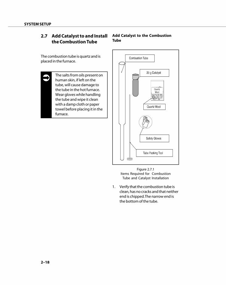
The salts from oils present onhuman skin, if left on thetube, will cause damage tothe tube in the hot furnace.Wear gloves while handlingthe tube and wipe it cleanwith a damp cloth or papertowel before placing it in thefurnace.
Add Catalyst to the CombustionTube
1. Verify that the combustion tube isclean, has no cracks and that neitherend is chipped. The narrow end isthe bottom of the tube.
Figure 2.7.1Items Required for Combustion
Tube and Catalyst Installation
2–19
SYSTEM SETUP
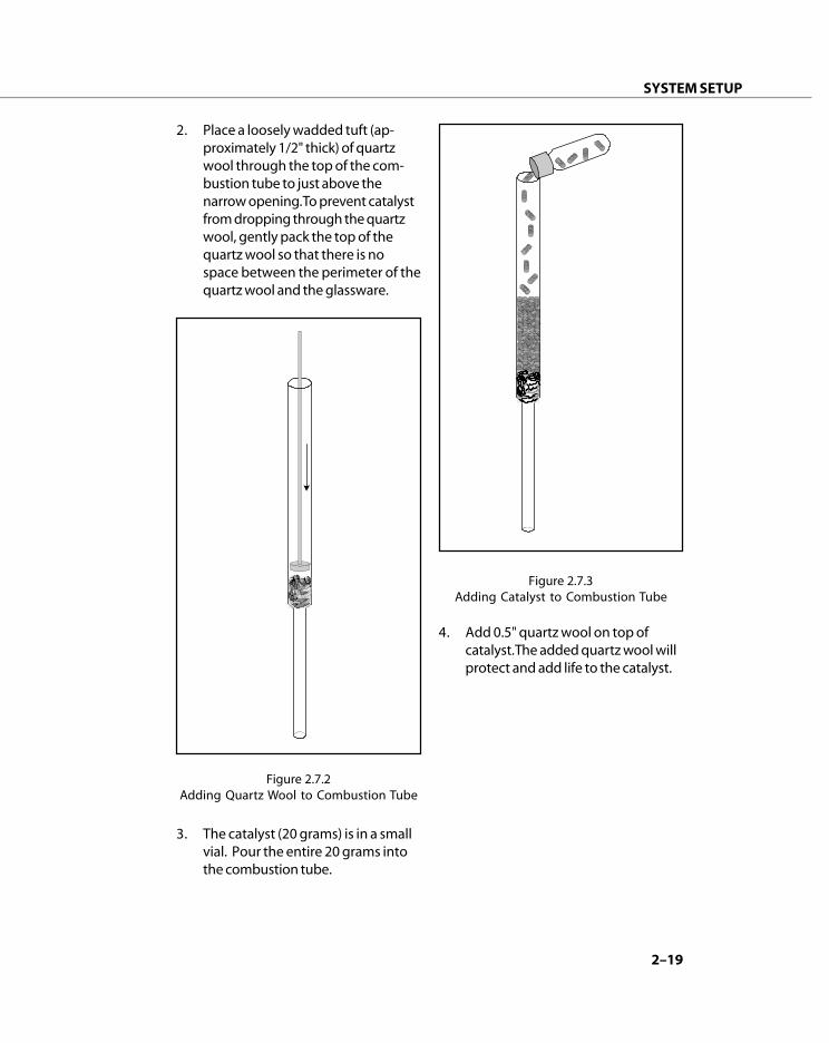
3. The catalyst (20 grams) is in a smallvial. Pour the entire 20 grams intothe combustion tube.
4. Add 0.5" quartz wool on top ofcatalyst. The added quartz wool willprotect and add life to the catalyst.
Figure 2.7.2Adding Quartz Wool to Combustion Tube
Figure 2.7.3Adding Catalyst to Combustion Tube
2. Place a loosely wadded tuft (ap-proximately 1/2" thick) of quartzwool through the top of the com-bustion tube to just above thenarrow opening. To prevent catalystfrom dropping through the quartzwool, gently pack the top of thequartz wool so that there is nospace between the perimeter of thequartz wool and the glassware.

2–20
SYSTEM SETUP
Install the Combustion Tube
1. Remove the right chassis cover fromthe Apollo 9000.
2. Detach the injection port from thevalve mounting plate by removingthe two screws and set aside.Remove the blue tube on the rightside for easier access to that screw.
3. Swing the locking guard at thebottom of the combustion furnaceto the right until it touches the rightfurnace leg.
4. Gently pull the bottom connectorout from under the furnace.
Examine the bottom connector forany debris on the black o-ring thatseals to the combustion tube. Ifnecessary, remove the connector atthe stainless steel union and rinse itunder clean, running water. Shakeout the excess water and gentlywipe the o-ring with a lint-freecloth.
5. Install the Combustion Tube bygently lowering it into the furnaceuntil the bottom end protrudes fromthe furnace. Hold the combustiontube in place until the bottomconnector is resecured.
a) Replace the bottom connectorand secure it in place byswinging the locking guard tothe left until it touches (ornearly touches) the left furnaceleg.
b) Contact with the o-ring will befelt. Push down firmly whileturning the tube slightly. Themovement of the tube throughthe o-ring should be felt. Whenproperly seated, about 1 1/2inches of tube should extendabove the plate.
6. The injection port seals to thecombustion tube with an o-ring.Examine the o-ring for any debris. Ifnecessary, wipe it gently.
a) If it is deemed necessary toremove the o-ring, do notattempt to pick it out with asharp instrument. Instead,remove the 4 screws that holdthe metal plate and spacerblock to the injection port. Itcan now be easily removed.
b) A new o-ring must be lubri-cated with a small amount ofsilicone vacuum grease.
c) With a tiny amount of lubricanton the fingertips, rub it on theo-ring.
d) Use a lab wipe and try to wipeall the lubricant away. Enoughwill be left to make it easy toslide the injection port onto thecombustion tube.
7. Slide the injection port onto thecombustion tube with gentlepressure and a slight turningmovement. Replace the screws.Reconnect the gas line above theright screw.

2–21
SYSTEM SETUP
2.8 Install TOC Talk Software
To install the Apollo 9000 TOC Talkprogram on Windows 95/98/NT:
1. Start Windows.
2. Close any open applications.
3. Place the Apollo 9000 TOC Talk CD-ROM into the CD-ROM drive. TheApollo 9000 CD Menu will appear.
4. Select the Apollo 9000 install icon.
5. Follow the installation prompts.
Note:TeledyneTekmar recommendsthat you accept the defaultinstallation directory on your harddrive for Apollo 9000 TOC Talk.
Configure Apollo 9000 withTOC Talk
Before you begin analyzing samples,TOC Talk must be configured to runApollo 9000 and its accessories.
To configure Apollo 9000 with TOCTalk:
1. Start Windows, and then click theStart button. Select TOC Talk fromthe Apollo 9000 Programsdirectory.
2. Select Instrument from the Setupmenu.
3. Type a name in the InstrumentName box for instrumentidentification.
4. Type a name (i.e., your name,name of group) in the OperatorName box for analysisidentifcation.
5. In System, select Ready mode.
6. Select relevant Options.
7. In Preferences, select the SampleIntroduction mode (With/WithoutAutosampler or RepetitiveSampling).
Note: Teledyne Tekmar recommendsthat you use the InstrumentSetup/Status defaults for theremaining options until youbecome more comfortable withApollo 9000 operation.
8. Click OK.

2–22
SYSTEM SETUP
2.9 Condition CombustionTube Catalyst
Before initial Apollo 9000 operation andeach time you install new catalyst, youmust condition the catalyst.
To condition the combustion tubecatalyst:
1. Disconnect the tube at the side-portof the Water Trap.
a) Attach a length of tubing to thattube so that the end can besubmerged in a beaker ofdiluted sodium hydroxidesolution. Some noxious gasesmay be emitted by the catalystupon conditioning and thewater will absorb them.
b) Set the carrier gas pressure to30 psig.
2. Elevate the temperature of thefurnace to 900°C by pressing the Setbutton on the Temperature Control-ler while pressing the Up arrowbutton. Wait until the furnacereaches 900°C.
3. Make sure the one liter DI watersupply vessel is filled.
4. Start TOC Talk.
5. Click Run in the main screen of theApollo 9000 software. This willbring you to the Sample Analysisscreen.
6. Click Sample Setup to access theSample Setup screen.
7. Whether in Autosampler or Auto-matic Syringe Mode, select Samplefrom the Sample Type list.
8. Select Condition Catalyst from theMethod ID list.
9. Enter 1001 as the vial number in thePos column if you use anautosampler. Water is taken fromthe DI water supply rather than froma vial.
10. Click Save/Use.
11. Click Start in the Sample Analysiswindow.
12. After the system completes theconditioning process (24 reps total),change the temperature settingback to 680°C and wait for thefurnace to cool.
13. Reconnect the water trap tube (seeStep 1).
14. After the temperature reaches680°C:
a) Autosampler Users:Place 5 vials of freshly-drawn DIwater into the autosampler vialtray. In Sample Setup, selectSample as Sample Type, TC 0-100 as the Method ID, and 5reps. Click on Save/Use andStart the run.
b) Automatic Syringe Users:Place the sample tube (con-nected to Port D of the 8-portvalve) into a container offreshly-drawn DI water or intothe DI water supply of theanalyzer. In Sample Setup,select TC 0-100 as the MethodID and 10 reps. After the 10reps finish, click Start again.After the second run, perform 5more reps.
15. The raw data count should finally beless than 30,000 counts for thestandard Apollo and Less than375,000 counts for the Apollo HS. Ifthe raw counts are greatly higher,then proceed to section 2.10.

2–23
SYSTEM SETUP
2.10 Cleaning Procedure forConditioned Catalyst
Fresh catalyst background might be toohigh for most applications. Before initialApollo 9000 operation and each timethe catalyst is replaced, the catalystconditioning procedure must be per-formed.
To condition the combustion tubecatalyst:
1. Make sure DI water vessel containsa minimum 1-liter supply.
2. Set the combustion furnace tem-perature to 900°C. Do not use thistemperature with old catalyst unlessit has been washed.
• Press and hold the Set buttonon the Temperature Controllerand then press the Up arrowbutton until the display reads900°C.
• Release both buttons and waituntil the furnace reaches900°C.
3. Run the TOC Talk Cleaning Proce-dure Method as a sample for 10replicates overnight in repetitivesampling mode every 5 minutes(the minimum time allowed).
4. The next day, exit the repetitivesampling procedure, return thecombustion furnace temperature to680°C, and run DI water as a TOCSample.
For applications measuring 1 ppmCsamples or less, the raw data for thissample should be:
• Less than 30000 area counts forthe standard Apollo 9000.
• Less than 375000 area countsfor the Apollo 9000 HS.
If your results do not approximate thesevalues and you are running sampleshigher than 1ppmC, it may be accept-able to run standards and samples.However, if you are running <1ppmCsamples, then repeat the conditioningprocedure to lower the raw data for yourDI water and background.
Note: Some systems may not have DIwater clean enough to meetthese guidelines. If you arerunning samples >1 ppmC, yourresults may be acceptable. Ifresults are not acceptable, thenTeledyen Tekmar recommendsusing an improved DI watersource.

2–24
SYSTEM SETUP
Notes:
__________________________________________________________________
__________________________________________________________________
__________________________________________________________________
__________________________________________________________________
__________________________________________________________________
__________________________________________________________________
__________________________________________________________________
__________________________________________________________________
__________________________________________________________________
__________________________________________________________________
__________________________________________________________________
__________________________________________________________________
__________________________________________________________________
__________________________________________________________________
__________________________________________________________________
__________________________________________________________________
__________________________________________________________________
__________________________________________________________________
__________________________________________________________________
__________________________________________________________________
__________________________________________________________________
__________________________________________________________________
__________________________________________________________________
__________________________________________________________________
__________________________________________________________________
__________________________________________________________________
__________________________________________________________________
__________________________________________________________________
__________________________________________________________________
__________________________________________________________________

TOC TALK
3

3–3
TOC TALK
3.1 TOC Talk Control Screen
The TOC Talk Control Screen appearswhen the TOC Talk software is started.
The Control screen contains menuswith keyboard shortcuts, setup options,the run option, results, and a status barthat depicts event list items in real timealong with mode status and currentNDIR mV output.
3.2 Instrument Setup
Before you begin analyzing samples,TOC Talk must be configured to runApollo 9000 and its accessories.
To access the Instrument Setup/StatusScreen, select Instrument from theSetup menu.
Figure 3.2 Instrument Setup/Status Screen
The Instrument Setup/Status Screen isthe main system configuration inter-face. In this screen you will configureTOC Talk to recognize your Apollo 9000system options.
Instrument Name
Type a name in this text box to identifythe Apollo system.
Operator Name
Enter a name (i.e., your name, name ofgroup) in this text box for analysisidentifcation.
Figure 3.1 TOC Talk Control Screen

3–4
TOC TALK
System
Select a system status mode for theApollo 9000 from the following:
• Ready turns on the permeationdryer gas and the combustionfurnace gas, and then routescarrier gas from the IC sparger tovent and from the combustionfurnace to the NDIR. In order toexecute a sample run, the instru-ment must be in Ready Mode.
• Standby turns the gas valves off.The NDIR and furnace remain on.Shutting off the NDIR will incur aminimum two hour stabilizationdelay upon startup. Tekmar-Dohrmann recommends thatApollo 9000 remain in StandbyMode when not in use.
• Sleep sends the instrument toStandby Mode and turns off thecombustion furnace, but maintainspower to the NDIR.
Gas Flow Rate (cc/min)
• To Furnace detects flow of carriergas to the combustion tube.
Options
• 0.8 mm Particulate Kit Installed
Select this option only if you havethe 0.8 mm Particulated SampleKit installed.
• Autosampler Sparge Option
Select this option only if you wantthe autosampler to sparge thesample (for TOC analysis) beforetransferring the sample to theApollo 9000.
Preferences
Select from the following options toconfigure the instrument specific toyour sample analysis requirements:
Sample Introduction
• Without Autosampler
• With Autosampler
• Repetitive Sampling
Max. Integration Time (min.)
• Time (in minutes) allotted for thereaction portion of an analysis totake place. Default is set to 4minutes.
Stabilize Baseline Time (sec.)
• Some analysis modes may requireadded wait between analyses toallow proper return of the baselineto a stable value. 15 seconds isrecommended.
Outlier Deletions
• Select the Outlier Deletion checkbox if you want to delete a certainnumber of outliers (maximum is 4)per sample analyzed.
Table 3.2Maximum Outlier Deletions
for Sample Rep Count
Reps Max. Deletions
3 1
4 1
5 2
6 3
7 4

3–5
TOC TALK
Print Data Report after Each SampleSet
• Select this option to send aprintout of the last sample set toyour default printer.
Auto Shutdown
• Check the Auto Shutdown optionbox to allow the instrument toautomatically run a shutdownevent list and go into StandbyMode after an autosampler run.This enables the automatic archiveutility when “ON” is selected in thearchive dialogue.
• Check the Auto Shutdown WithFurnace Off option box if you wantthe shutdown event list to includeturning the combustion furnaceoff during unit shutdown. Thisoption is only available when AutoShutdown is also selected.
Halt System If Out of Calibration orOver Range
You can select one or both options ifyou want your analysis sequencehalted when TOC Talk detects calibra-tion or range errors.
• Check the Out of Calibrationoption box if you want the sched-uled analysis sequence to haltwhen TOC Talk detects that Apollo9000 has slipped out of thedesired calibration.
• Check the Over Range option boxif you want the scheduled analysissequence to halt when TOC Talkdetects that Apollo 9000 hasdetected a sample that has goneout of its analysis range.

3–6
TOC TALK
Gas Output
CAUTION
When Valves 4 and 5 are onto direct the IC Sparger flowto the NDIR, Valve 2 must beoff. Failure to turn Valve 2off when Valves 4 and 5 areon could result indangerous pressurization ofthe combustion tube andwater trap.
Select where you want the followingcombustion furnace and IC spargeroutput sample gases to go:
• Furnace Gas To either Vent orNDIR. [Valve 4]
• IC Gas To either NDIR orVent. [Valve 5]
Auxiliary
• Furnace Power controls power tothe combustion furnace. Thedefault setting is Off.
3.3 Instrument Diagnostics
Valves
On the Setup menu, point to Diagnos-tics, and then click Valves.
Figure 3.3.1Diagnostics Valve Control Screen
Gas Input
Select On or Off for each of the Apollo9000 components you want gascarried to:
• Permeation Dryer turns gas on tothe permeation dryer (200cc/min). [Valve 1]
• Furnace turns gas on to thecombustion furnace. [Valve 2]
• IC Sparger turns gas on to the ICsparger. [Valve 3]
• ASM Sparge turns gas on to theautosampler. [Valve 7]
WARNING!
Do not alter this screen duringan analysis. Erroneous orconflicting data can damagethe instrument.

3–7
TOC TALK
Syringe Pump and 8-port ValveDiagnostics
On the Setup menu, point to Diagnos-tics, and then click Syringe.
Figure 3.3.2Diagnostics Syringe Pump &8-port Valve Control Screen
A = Acid E = Not Used
B = IC Reactor F = Waste
C = Furnace G = DI Water
D = Sample H = Water Trap
• Home Position Button
Automatically switches the outerport of the 8-port valve to positionA (Acid).
Syringe Volume Position (µL)
• Current Position
Displays current position of thesyringe in microliters.
• Move To Volume
You can move the syringe byentering the absolute position ofthe syringe in microliters andclicking the Move button.
Example:If you want to pull 1000 µL from asyringe already located at 200 µL,enter 1200µL in the Move toVolume field and click the Movebutton.
• Home Position Button
Automatically moves the syringeto 0 µL and the valve to the wasteposition while discarding syringecontents.
Note: Updating the current positionduring analysis may result incommunication and data loss.
Valve Position
• Current Position
Displays current position of theouter port of the 8-port valve. Thecommon port is always connectedto the syringe.
• Move To Position
You can choose the outer portposition here by clicking on thepull down window or the displaybox and then clicking on the Movebutton.
WARNING!
Do not alter this screenduring an analysis. Erroneousor conflicting data candamage the instrument.

3–8
TOC TALK
Autosampler Diagnostics
On the Setup menu, point to Diagnos-tics, and then click Autosampler.
Figure 3.4 Autosampler Diagnostics Screen
Rack Style
• Select the rack style you are usingby clicking the pull down menu orthe display box.
Manual Movement
• Home
Click this button to home theautosampler
• Move To Vial
Click this button to move theautosampler needle to the posi-tion selected in the display box tothe right of the button. The posi-tion number can be changed byclicking the arrow bar or thedisplay box.
Note: Special Position Numbers:
• 1001 thru 1014support bar ports
• 1015Rinse Station
• Needle Down
Moves autosampler needle down
• Needle Up
Moves autosampler needle up
Current Positions (mm)
This section displays the currentposition (in millimeters) of theautosampler in the X, Y, and Z planeswhen the Update button is activated.
WARNING!
Do not alter this screenduring an analysis. Erroneousor conflicting data candamage the instrument.

3–9
TOC TALK
Communications Diagnostics
On the Setup menu, point to Diagnos-tics, and then click Communications.
Figure 3.3.4Communications Diagnostics Screen
The Communications DiagnosticsScreen allows you to switch thecommunications port or re-establishcommunications when necessary.
• COM Port Selection
Select the correct Communicationport from the computer to theApollo 9000 here from list. TOCTalk automatically configures theCOM port (a free COM port isrequired).
• OK Button
Select OK to accept the portselection and re-initialize theApollo 9000.
WARNING!
Selecting the OK button maycompromise the data of thecurrent run.
• Cancel Button
Select Cancel to exit the communi-cations screen without re-assign-ing the port and without re-initializing the Apollo 9000.
Flowmeter Calibration Diagnostics
On the Setup menu, point to Diagnos-tics, and then click Flowmeter Calibra-tion.
The flow to the furnace can be mea-sured with an independent flowmeterfrom the 1/8" blue gas line entering theside of the injection port over thecombustion furnace (the right sidecover must be removed to do this).Once the actual flow for the flowmeteris known, type its value (in units of cc/min) into the Actual field. When theflowmeter reading is stable, click theCalibrate button. The ratio of Actualflow to raw flow will be displayed inthe Cal. Factor field.
Figure 3.3.5Flowmeter Calibration Diagnostic Screen

3–10
TOC TALK
3.4 Archive Data
On the Setup menu, click Archive.
Figure 3.4 Archive Settings Screen
Automatic Archive
TOCTalk automates the process of dataarchive with its Archive utility. Whenenabled, TOCTalk creates a new direc-tory tree, copies all files to the newlocation, and deletes them from theiroriginal location while leaving theoriginal directory structure intact.Archival occurs up to the present daywhen the interval in days has beenreached, the system mode is inStandby, and the TOC Talk software ison.
1. Enter an interval (number of days)value in the first field.
2. Either type in a new file path forthe backup files to be createdunder or accept the default(C:\APOLLO\ARCHIVE) path.
3. Select On in the Automatic ArchiveUtility Status.
4. Click OK.
Manual Archive
You may prefer to have more controlover archival of your data files.
1. Specify a file path for the archivefiles to be created under or acceptthe default (C:\APOLLO\ARCHIVE)path.
2. Click Archive Now. A dialogue willappear on your screen indicatingthat the archive was successful.
3. Click OK.
3–11
TOC TALK
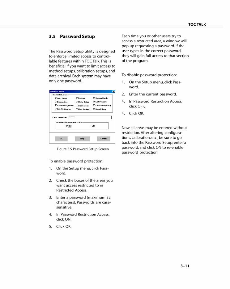
3.5 Password Setup
The Password Setup utility is designedto enforce limited access to control-lable features within TOC Talk. This isbeneficial if you want to limit access tomethod setups, calibration setups, anddata archival. Each system may haveonly one password.
Figure 3.5 Password Setup Screen
To enable password protection:
1. On the Setup menu, click Pass-word.
2. Check the boxes of the areas youwant access restricted to inRestricted Access.
3. Enter a password (maximum 32characters). Passwords are case-sensitive.
4. In Password Restriction Access,click ON.
5. Click OK.
Each time you or other users try toaccess a restricted area, a window willpop up requesting a password. If theuser types in the correct password,they will gain full access to that sectionof the program.
To disable password protection:
1. On the Setup menu, click Pass-word.
2. Enter the current password.
4. In Password Restriction Access,click OFF.
4. Click OK.
Now all areas may be entered withoutrestriction. After altering configura-tions, calibration, etc., be sure to goback into the Password Setup, enter apassword, and click ON to re-enablepassword protection.
3–12
TOC TALK
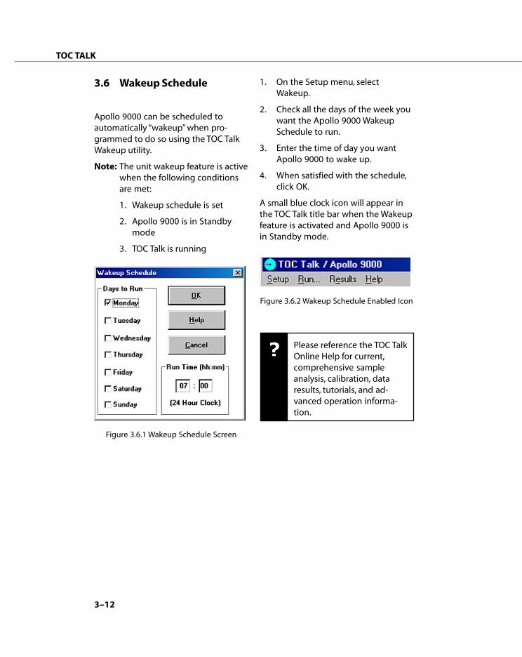
3.6 Wakeup Schedule
Apollo 9000 can be scheduled toautomatically “wakeup” when pro-grammed to do so using the TOC TalkWakeup utility.
Note: The unit wakeup feature is activewhen the following conditionsare met:
1. Wakeup schedule is set
2. Apollo 9000 is in Standbymode
3. TOC Talk is running
Figure 3.6.1 Wakeup Schedule Screen
1. On the Setup menu, selectWakeup.
2. Check all the days of the week youwant the Apollo 9000 WakeupSchedule to run.
3. Enter the time of day you wantApollo 9000 to wake up.
4. When satisfied with the schedule,click OK.
A small blue clock icon will appear inthe TOC Talk title bar when the Wakeupfeature is activated and Apollo 9000 isin Standby mode.
Figure 3.6.2 Wakeup Schedule Enabled Icon
Please reference the TOC TalkOnline Help for current,comprehensive sampleanalysis, calibration, dataresults, tutorials, and ad-vanced operation informa-tion.
CALIBRATION
4

4–3
CALIBRATION
4.1 System Calibration
Before analyses, Apollo 9000 must becalibrated. A response factor correlatesthe raw counts of the instrument to aknown amount of carbon in a sample, orwhat is referred to as a standard. Stan-dards are made by adding carbon toultra-pure water to achieve determinedlevels of carbon. It is important to usethe same source of water for all calibra-tion standards because the carbon in thepreparation water is part of the calibra-tion curve.
Note: Once Apollo 9000 standardcalibration is performed, all youhave to do is assign appropri-ate, active calibration curvesprior to sample analyses. You donot need to perform thecalibration procedure for eachsample run.
Standard analyses have, in general, threemajor sources of carbon content:measured carbon content added to theultra-pure water, carbon from thepreparation water itself, and carbonassociated with the reagents used toperform the relevant analysis. When wecalibrate the instrument to a y=mx+blinear fit, the constant carbon contribu-tion of the prep water and the reagentare represented by the y-intercept, b
cal:
y = mx + b cal
b cal = b reagent + b rinse water
The slope of the curve, m, represents therelationship of the measured carbon inthe standard to the response of theinstrument since only this source ofcarbon changes between any set ofstandards.
Note: Running your preparationwater as a "zero" standard canbe an excellent way to cali-brate the low end of theconcentration range for low-level methods.
After calibration, the slope m will beused as our response factor in sampleanalysis. However, the y-intercept,b
cal, will not be used because the carbon
associated with a blank may change overtime. To address this issue, special blankmethods can be run at anytime. Thelinear equation for samples is simplyy=mx + b
new.
For 0–20, 1–400 ppm TOC and TCmethods, the carbon contribution fromthe preparation water that is present instandards but not samples may besignificant. The blank method in thisrange uses rinse water from the rinsewater bottle, continuously recycles itthrough the furnace for a period of time,and then measures the water derived asthe sample blank. To run a check stan-dard against the calibration curve, youmust then run the standard as a calibra-tion verification instead of a sample. Thiscalibration verification sample type willapply the correct blank, the y-interceptor b
cal, to the analysis.

4–4
CALIBRATION
4.2 Standard CalibrationWithout AutosamplerTutorial
IMPORTANTPrecisely follow the stepsbelow to achieve successfulcalibration of your Apollo9000 instrument.
In this exercise, you will create a stan-dard calibration for low-level TOCsample analysis by setting up threecalibration points.
You will:1. Define the Standard Calibration
Methods and Concentrations2. Set the Active Calibration Curve3. Setup the Standard Calibration
Analysis4. Start the Standard Calibration
Analysis Run5. Review the Analysis Results
Figure 4.1 Calibration Slope
Mass (µgC)100
Det
ecto
r Ou
tpu
t (Ra
w D
ata)
Water Contribution
Reagent Contribution
4 Calibration Points:25, 50, 75, and 100 ppm
Slope = calibration factorIntercept = calibration blank
4–5
CALIBRATION
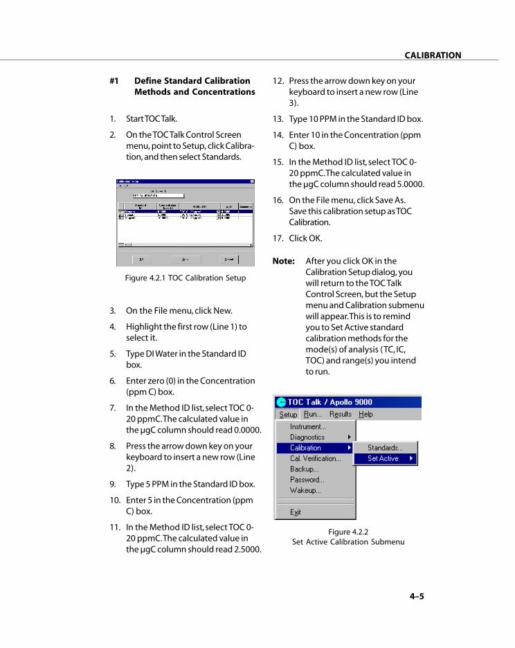
Note: After you click OK in theCalibration Setup dialog, youwill return to the TOC TalkControl Screen, but the Setupmenu and Calibration submenuwill appear. This is to remindyou to Set Active standardcalibration methods for themode(s) of analysis (TC, IC,TOC) and range(s) you intendto run.
Figure 4.2.2Set Active Calibration Submenu
#1 Define Standard CalibrationMethods and Concentrations
1. Start TOC Talk.
2. On the TOC Talk Control Screenmenu, point to Setup, click Calibra-tion, and then select Standards.
Figure 4.2.1 TOC Calibration Setup
3. On the File menu, click New.
4. Highlight the first row (Line 1) toselect it.
5. Type DI Water in the Standard IDbox.
6. Enter zero (0) in the Concentration(ppm C) box.
7. In the Method ID list, select TOC 0-20 ppmC. The calculated value inthe µgC column should read 0.0000.
8. Press the arrow down key on yourkeyboard to insert a new row (Line2).
9. Type 5 PPM in the Standard ID box.
10. Enter 5 in the Concentration (ppmC) box.
11. In the Method ID list, select TOC 0-20 ppmC. The calculated value inthe µgC column should read 2.5000.
12. Press the arrow down key on yourkeyboard to insert a new row (Line3).
13. Type 10 PPM in the Standard ID box.
14. Enter 10 in the Concentration (ppmC) box.
15. In the Method ID list, select TOC 0-20 ppmC. The calculated value inthe µgC column should read 5.0000.
16. On the File menu, click Save As.Save this calibration setup as TOCCalibration.
17. Click OK.

4–6
CALIBRATION
#2 Set Active Calibration Curve
1. From the Set Active submenu,select TOC Curve.
Figure 4.2.3TOC Mode—Active Calibration Curves
2. In the 0-20, 1-400 Range list, selectthe TOC Calibration CalibrationCurve ID. "TOC Calibration" is thename you gave the CalibrationSetup. TOC Talk will use the ActiveCalibration Curve (TOC Calibrationsetup for the 0-20, 1-400 Range)data from the standards to analyzecalibration.
Note: TOC Talk references the ActiveCalibration Curves, which are filesthat store the informationassociated with a specific Calibra-tion Curve ID or Method ID,during sample runs. If you want toanalyze a standard, you must firstcreate a Calibration Setup tableand then set the Active Calibra-tions Curves. Once you save thestandard concentrations (Calibra-tion Curve IDs) and set as Active,TOC Talk will automatically referto the current standard calibrationconfiguration when Standard isselected as the Sample Type foranalysis.
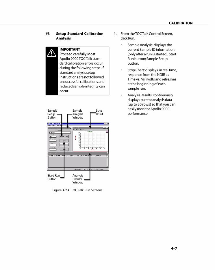
4–7
CALIBRATION
#3 Setup Standard CalibrationAnalysis
IMPORTANTProceed carefully. MostApollo 9000 TOC Talk stan-dard calibration errors occurduring the following steps. Ifstandard analysis setupinstructions are not followedunsuccessful calibrations andreduced sample integrity canoccur.
Figure 4.2.4 TOC Talk Run Screens
1. From the TOC Talk Control Screen,click Run.
• Sample Analysis: displays thecurrent Sample ID information(only after a run is started); StartRun button; Sample Setupbutton.
• Strip Chart: displays, in real time,response from the NDIR asTime vs. Millivolts and refreshesat the beginning of eachsample run.
• Analysis Results: continuouslydisplays current analysis data(up to 30 rows) so that you caneasily monitor Apollo 9000performance.

4–8
CALIBRATION
Figure 4.2.5 Standard Calibration Analysis Setup (without Autosampler)
5. Next the Select Calibrator dialogappears. Select the Standard ID (DIWATER) you want to use by clickingon its row to highlight it. Click Exit.You will return to the Analysis Setupscreen. TOC Talk automaticallyinserts the calibration information inthe Sample ID and Method ID fields.
6. Select the Number of Reps PerSample in the Reps column.
7. Click Save/Use.
2. Click Sample Setup in the SampleAnalysis screen.
3. From the Sample Type list, selectTOC Standard.
4. The Choose Range dialog appears.Select the 0-20, 1-400 range. ClickOK.
SelectRange;Click OK
SelectSampleType
Click on StandardCalibration Line;click Exit
SelectNumberRepsPerSample
Click Save/Use
2
3
4
5
1
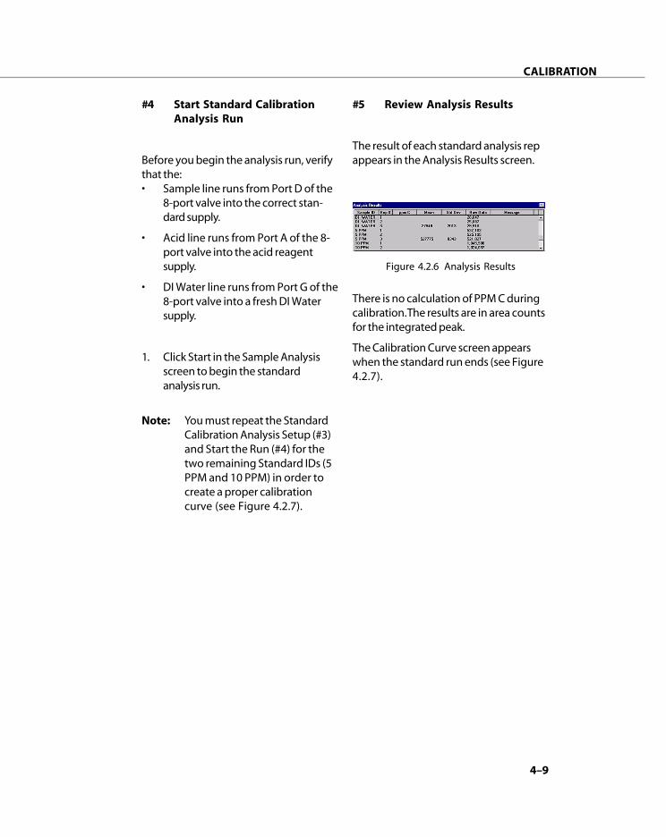
4–9
CALIBRATION
#4 Start Standard CalibrationAnalysis Run
Before you begin the analysis run, verifythat the:• Sample line runs from Port D of the
8-port valve into the correct stan-dard supply.
• Acid line runs from Port A of the 8-port valve into the acid reagentsupply.
• DI Water line runs from Port G of the8-port valve into a fresh DI Watersupply.
1. Click Start in the Sample Analysisscreen to begin the standardanalysis run.
Note: You must repeat the StandardCalibration Analysis Setup (#3)and Start the Run (#4) for thetwo remaining Standard IDs (5PPM and 10 PPM) in order tocreate a proper calibrationcurve (see Figure 4.2.7).
#5 Review Analysis Results
The result of each standard analysis repappears in the Analysis Results screen.
Figure 4.2.6 Analysis Results
There is no calculation of PPM C duringcalibration. The results are in area countsfor the integrated peak.
The Calibration Curve screen appearswhen the standard run ends (see Figure4.2.7).
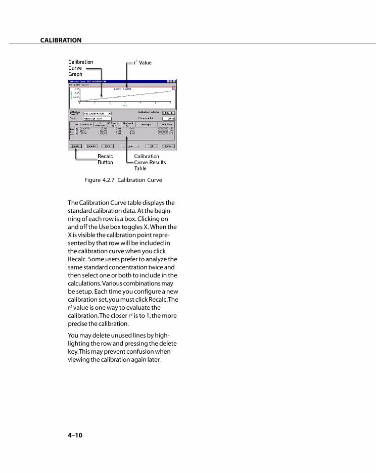
4–10
CALIBRATION
Figure 4.2.7 Calibration Curve
The Calibration Curve table displays thestandard calibration data. At the begin-ning of each row is a box. Clicking onand off the Use box toggles X. When theX is visible the calibration point repre-sented by that row will be included inthe calibration curve when you clickRecalc. Some users prefer to analyze thesame standard concentration twice andthen select one or both to include in thecalculations. Various combinations maybe setup. Each time you configure a newcalibration set, you must click Recalc. Ther2 value is one way to evaluate thecalibration. The closer r2 is to 1, the moreprecise the calibration.
You may delete unused lines by high-lighting the row and pressing the deletekey. This may prevent confusion whenviewing the calibration again later.

4–11
CALIBRATION
4.3 Standard Calibration WithAutosampler Tutorial
Note: Precisely follow the stepsbelow to achieve successfulcalibration of your Apollo 9000instrument.
In this exercise, you will create astandard calibration for low-level TOCsample analysis by setting up threecalibration points.
You will:
#1 Define the Standard CalibrationMethods and Concentrations
#2 Set the Active Calibration Curve
#3 Setup the Standard CalibrationAnalysis
#4 Start the Standard CalibrationAnalysis Run
#5 Review the Analysis Results
#1 Define Standard CalibrationMethods and Concentrations
1. Start TOC Talk.
2. On the TOC Talk Control Screenmenu, point to Setup, click Calibra-tion, and then select Standards.
3. On the File menu, click New.
4. Highlight the first row (Line 1) toselect it.
5. Type DI Water in the Standard IDbox.
6. Enter zero (0) in the Concentration(ppm C) box.
7. In the Method ID list, select TOC 0-20 ppmC. The calculated value inthe µgC column should read 0.0000.
8. Press the arrow down key on yourkeyboard to insert a new row (Line2).
9. Type 5 PPM in the Standard ID box.
10. Enter 5 in the Concentration(ppm C) box.
Figure 4.3.1 TOC Calibration Setup
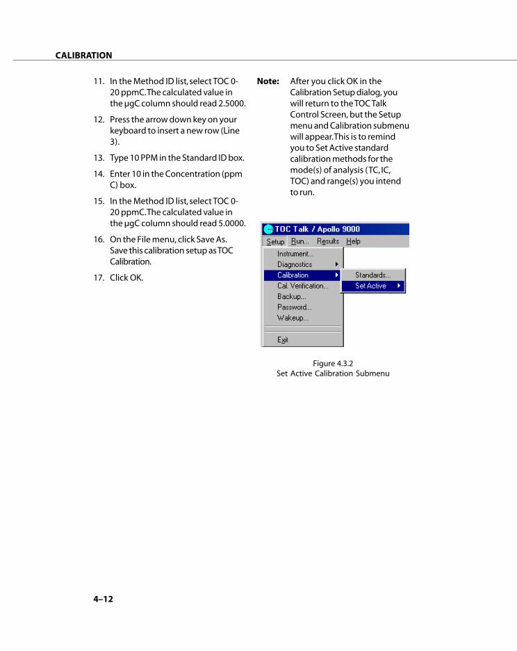
4–12
CALIBRATION
Note: After you click OK in theCalibration Setup dialog, youwill return to the TOC TalkControl Screen, but the Setupmenu and Calibration submenuwill appear. This is to remindyou to Set Active standardcalibration methods for themode(s) of analysis (TC, IC,TOC) and range(s) you intendto run.
11. In the Method ID list, select TOC 0-20 ppmC. The calculated value inthe µgC column should read 2.5000.
12. Press the arrow down key on yourkeyboard to insert a new row (Line3).
13. Type 10 PPM in the Standard ID box.
14. Enter 10 in the Concentration (ppmC) box.
15. In the Method ID list, select TOC 0-20 ppmC. The calculated value inthe µgC column should read 5.0000.
16. On the File menu, click Save As.Save this calibration setup as TOCCalibration.
17. Click OK.
Figure 4.3.2Set Active Calibration Submenu
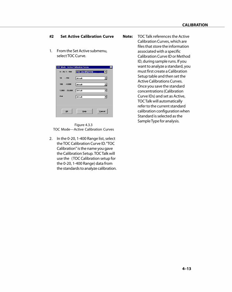
4–13
CALIBRATION
#2 Set Active Calibration Curve
1. From the Set Active submenu,select TOC Curve.
2. In the 0-20, 1-400 Range list, selectthe TOC Calibration Curve ID. "TOCCalibration" is the name you gavethe Calibration Setup. TOC Talk willuse the (TOC Calibration setup forthe 0-20, 1-400 Range) data fromthe standards to analyze calibration.
Figure 4.3.3TOC Mode—Active Calibration Curves
Note: TOC Talk references the ActiveCalibration Curves, which arefiles that store the informationassociated with a specificCalibration Curve ID or MethodID, during sample runs. If youwant to analyze a standard, youmust first create a CalibrationSetup table and then set theActive Calibrations Curves.Once you save the standardconcentrations (CalibrationCurve IDs) and set as Active,TOC Talk will automaticallyrefer to the current standardcalibration configuration whenStandard is selected as theSample Type for analysis.

4–14
CALIBRATION
#3 Setup Standard CalibrationAnalysis
Note: Proceed carefully. Most Apollo9000 TOC Talk standard calibra-tion errors occur during thefollowing steps. If standardanalysis setup instructions arenot followed unsuccessfulcalibrations and reducedsample integrity can occur.
1. From the TOC Talk Control Screen,click Run.
• Sample Analysis: displays thecurrent Sample ID information(only after a run is started); StartRun button; Sample Setupbutton.
• Strip Chart: displays, in real time,response from the NDIR asTime vs. Millivolts and refreshesat the beginning of eachsample run.
• Analysis Results: continuouslydisplays current analysis data(up to 30 rows) so that you caneasily monitor Apollo 9000performance.
2. Click Sample Setup in the SampleAnalysis screen.
3. Enter the autosampler vial positionin the Pos column (see Figure4.3.5).
4. From the Sample Type list, selectTOC Standard.
Note: You must physically select aSample Type from the listalthough the one you wantmay already be displayed foreach line you set up.
5. The Choose Range dialog appears.Select the 0-20, 1-400 range. ClickOK.
Figure 4.3.4 TOC Talk Run Screens

4–15
CALIBRATION
6) Next the Select Calibrator dialogappears. Select the Standard ID (DIWater) you want to use by clickingon its row to highlight it. Click Exit.You will return to the AutosamplerAnalysis Setup screen. TOC Talkautomatically inserts the calibrationinformation in the Sample ID andMethod ID fields.
7) Select the Number of Reps PerSample in the Reps column.
Figure 4.3.5 Standard Calibration Analysis Setup (with Autosampler)
8) Press the arrow down or Insert keyon your keyboard or select InsertRow from the File menu to insertanother row.
9) Repeat steps 4-8 to enter the tworemaining Sample IDs (5 PPM and10 PPM).
10) Click Save/Use to return to the Runscreens. Recalling this autosampleranalysis setup will allow immediaterecalibration (without going throughall the steps again) as long as thecalibration standards table is notdeleted.
EnterSampleVialPosition
Select SampleType
SelectRange;Click OK
SelectStandardCalibrationLine;Click Exit
SelectNumberReps PerSample
ClickSave/Use
1
23
4
5
6
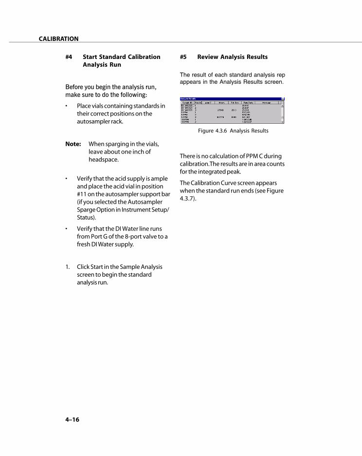
4–16
CALIBRATION
#4 Start Standard CalibrationAnalysis Run
Before you begin the analysis run,make sure to do the following:
• Place vials containing standards intheir correct positions on theautosampler rack.
Note: When sparging in the vials,leave about one inch ofheadspace.
• Verify that the acid supply is ampleand place the acid vial in position#11 on the autosampler support bar(if you selected the AutosamplerSparge Option in Instrument Setup/Status).
• Verify that the DI Water line runsfrom Port G of the 8-port valve to afresh DI Water supply.
1. Click Start in the Sample Analysisscreen to begin the standardanalysis run.
#5 Review Analysis Results
The result of each standard analysis repappears in the Analysis Results screen.
There is no calculation of PPM C duringcalibration. The results are in area countsfor the integrated peak.
The Calibration Curve screen appearswhen the standard run ends (see Figure4.3.7).
Figure 4.3.6 Analysis Results

4–17
CALIBRATION
The Calibration Curve table displays thestandard calibration data. At the begin-ning of each row is a box. Clicking onand off the Use box toggles X. When theX is visible the calibration point repre-sented by that row will be included inthe calibration curve when you clickRecalc. Some users prefer to analyze thesame standard concentration twice andthen select one or both to include in thecalculations. Various combinations maybe setup. Each time you configure a newcalibration set, you must click Recalc. Ther2 value is one way to evaluate thecalibration. The closer r2 is to 1, the moreprecise the calibration.
You may delete unused lines by high-lighting the row and pressing the deletekey. This may prevent confusion whenviewing the calibration again later.
Figure 4.3.7 Calibration Curve

4–18
CALIBRATION
Notes:
__________________________________________________________________
__________________________________________________________________
__________________________________________________________________
__________________________________________________________________
__________________________________________________________________
__________________________________________________________________
__________________________________________________________________
__________________________________________________________________
__________________________________________________________________
__________________________________________________________________
__________________________________________________________________
__________________________________________________________________
__________________________________________________________________
__________________________________________________________________
__________________________________________________________________
__________________________________________________________________
__________________________________________________________________
__________________________________________________________________
__________________________________________________________________
__________________________________________________________________
__________________________________________________________________
__________________________________________________________________
__________________________________________________________________
__________________________________________________________________
__________________________________________________________________
__________________________________________________________________
__________________________________________________________________
__________________________________________________________________
__________________________________________________________________
__________________________________________________________________
__________________________________________________________________

SAMPLE ANALYSIS
5

5–3
SAMPLE ANALYSIS
5.1 Sample Analysis
The following tutorials will guide youthrough the Apollo 9000 default TOCsample analysis procedure.
You will:
1. Configure the Instrument
2. Setup the Sample
3. Start the Analysis Run
5.2 Tutorial:TOC Results Made EasyWithout Autosampler
#1 Configure Instrument
1. Select Instrument from the Setupmenu of the TOC Talk Controlscreen to open the InstrumentSetup/Status dialog.
2. Select Ready to wake up theinstrument.
3. The gas flow will turn on and thedetector signal will begin tostabilize. Look for the flow ratedisplay in the To Furnace field.
4. Select the following parameters:
a) Select Without Autosamplerfrom the Sample Introductionlist.
b) Check Print Data Report afterEach Sample Set (optional).
c) If you wish, you may type inyour name and give yourinstrument a name. All otherchoices should remain un-checked.
5. Click OK.
Figure 5.2.1 Instrument Setup/Status

5–4
SAMPLE ANALYSIS
3. Click the Sample Setup button inthe Sample Analysis screen.
4. In the Without AutosamplerAnalysis Setup screen, enter aname for the sample run in theSample ID field.
5. Select Sample from the SampleType list.
6. Select TOC 0-20 ppmC from theMethod ID list. The analysis Modedisplayed should match theMethod and the Calibration Curveshould display the default unlessanother curve is set as active andin memory.
#2 Sample Setup
1. From the menu bar of the Controlscreen, click Run.
2. The Run screens are actually threeseparate screens that display real-time data:
a) Sample Analysis displays thelast Sample ID, Mode, etc. if notrunning or the current SampleID, etc. while running. TheSample Setup button accessesthe Sample Setup table.
b) Strip Chart shows the detectorsignal and can be changed tomagnify small peaks oraccommodate larger peaks.
c) Analysis Results updatesanalysis data at the end ofeach sample analysis rep.
Figure 5.2.2 Access to Run Screens
Figure 5.2.3 TOC Talk Run Screens
Figure 5.2.4Analysis Setup (without Autosampler)
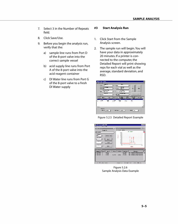
5–5
SAMPLE ANALYSIS
#3 Start Analysis Run
1. Click Start from the SampleAnalysis screen.
2. The sample run will begin. You willhave your data in approximately20 minutes. If a printer is con-nected to the computer, theDetailed Report will print showingreps for each vial as well as theaverage, standard deviation, andRSD.
7. Select 3 in the Number of Repeatsfield.
8. Click Save/Use.
9. Before you begin the analysis run,verify that the:
a) sample line runs from Port Dof the 8-port valve into thecorrect sample vessel
b) acid supply line runs from PortA of the 8-port valve into theacid reagent container
c) DI Water line runs from Port Gof the 8-port valve to a freshDI Water supply
Figure 5.2.5 Detailed Report Example
Figure 5.2.6Sample Analysis Data Example

5–6
SAMPLE ANALYSIS
2. Select Ready to wake up theinstrument.
3. The gas flow will turn on and thedetector signal will begin tostabilize. Look for the flow ratedisplay in the To Furnace field.
4. Select the following parameters:
a) Select With Autosampler fromthe Sample Introduction List.
b) Select Autosampler SpargeOption.
c) Check Print Data Report afterEach Sample Set (optional).
d) If you wish, you may type inyour name and give yourinstrument a name. All otherchoices should remain un-checked.
5. Click OK.
#2 Sample Setup
1. From the menu bar of the Controlscreen, click Run.
2. The Run screen has three parts,Sample Analysis, Strip Chart andAnalysis Result.
a) Sample Analysis displays thelast Sample ID, Mode, etc. if notrunning or the current SampleID, etc. while running. TheSample Setup button accessesthe Sample Setup table.
b) Strip Chart shows the detectorsignal and can be changed tomagnify small peaks oraccommodate larger peaks.
c) Analysis Results updates itsanalysis data at the end ofeach sample analysis rep.
5.3 Tutorial:TOC Results Made EasyWith Autosampler
#1 Configure Instrument
1. Select Instrument from the Setupmenu to open the InstrumentSetup/Status dialog.
Figure 5.3.1 Instrument Setup/Status
Figure 5.3.2 Access to Run Screens
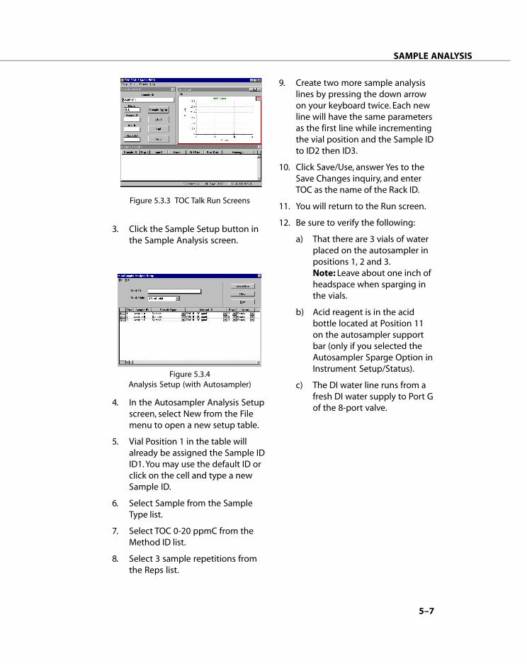
5–7
SAMPLE ANALYSIS
3. Click the Sample Setup button inthe Sample Analysis screen.
4. In the Autosampler Analysis Setupscreen, select New from the Filemenu to open a new setup table.
5. Vial Position 1 in the table willalready be assigned the Sample IDID1. You may use the default ID orclick on the cell and type a newSample ID.
6. Select Sample from the SampleType list.
7. Select TOC 0-20 ppmC from theMethod ID list.
8. Select 3 sample repetitions fromthe Reps list.
Figure 5.3.3 TOC Talk Run Screens
Figure 5.3.4Analysis Setup (with Autosampler)
9. Create two more sample analysislines by pressing the down arrowon your keyboard twice. Each newline will have the same parametersas the first line while incrementingthe vial position and the Sample IDto ID2 then ID3.
10. Click Save/Use, answer Yes to theSave Changes inquiry, and enterTOC as the name of the Rack ID.
11. You will return to the Run screen.
12. Be sure to verify the following:
a) That there are 3 vials of waterplaced on the autosampler inpositions 1, 2 and 3.Note: Leave about one inch ofheadspace when sparging inthe vials.
b) Acid reagent is in the acidbottle located at Position 11on the autosampler supportbar (only if you selected theAutosampler Sparge Option inInstrument Setup/Status).
c) The DI water line runs from afresh DI water supply to Port Gof the 8-port valve.

5–8
SAMPLE ANALYSIS
#3 Start Analysis Run
1. Click Start from the SampleAnalysis screen.
2. The sample run will begin. You willhave your data in approximately45 minutes. If a printer is con-nected to the computer, theDetailed Report will print showingreps for each vial as well as theaverage, standard deviation, andRSD.
Figure 5.3.5 Example
Please reference the TOC TalkOnline Help for current,comprehensive sampleanalysis, calibration, dataresults, tutorials, and ad-vanced operation informa-tion.

5–9
SAMPLE ANALYSIS
5.4 Sample Blanks
5.4.1 Manually Set the SampleBlank
Teledyne Tekmar recommendssetting the blank value to the raw datavalue of your DI water run as a sample.
To set this up, go to the Sample BlanksReview screen in the Results menu andenter the correct raw data for thedesired range of analysis.
Enter the values into Blank1, Blank2, orBlank3 or even one value into any ofthe 3 blank spaces.
Table 5.4.1 outlines the blank ranges asthey correlate to the standard meth-ods.
Table 5.4.1 Blank Ranges
Sample Type & Method IDRange (ppmC)
TOC, TC 0-20 TOC_TC Rng 1
TOC, TC 1-400 TOC_TC Rng 1
TOC, TC 10-750 TOC_TC Rng 2
TOC, TC 100-4000 TOC_TC Rng 3
TOC, TC 1000-25000 TOC_TC Rng 3
IC 0-20 IC Range 1
IC 1-400 IC Range 1
IC 10-750 IC Range 2
IC 100-4000 IC Range 3

5–10
SAMPLE ANALYSIS
Sample Method ID Blank Sample ID Blank Method ID
TOC, TC 0-20ppmC Blank TOC_TC Rng 1 Blank TOC_TC Rng 1
TOC, TC 1-400ppmC Blank TOC_TC Rng 1 Blank TOC_TC 1-400ppmC*
TOC, TC 10-750ppmC Blank TOC_TC Rng 2 Blank TOC_TC Rng 2
TOC, TC 100-4000ppmC Blank TOC_TC Rng 3 Blank TOC_TC Rng 3
TOC, TC 1000-25000ppmC Blank TOC_TC Rng 3 Blank TOC_TC Rng 3
* When TOC_TC Blank Range 1 is chosen, TOC_TC 0-20ppmC will automatically be set as the Method ID. Make sure to change this to TOC_TC 1-400 ppmC.
Table 5.4.2 TOC, TC Sample Blanks
5.4.2 Run Recirculating TOCand TC Blanks
If the DI water contribution to yourstandards is significant to your analysis,you may want to run a recirculatingblank method.
The blanking procedure for TC and TOCanalysis will recycle DI water throughthe furnace and then sample from thewater trap to determine the sampleblank value. Make sure to set thenumber of replicates to, at least, 6when running a sample blankingprocedure.
The results for blank methods are inraw data counts and the last 3 repli-cates are averaged as the sampleblank.
Note: The raw data value for thesample blank should be less than theraw data for your DI water run as a TOCsample. If it is not,Teledyne Tekmarrecommends rerunning the sampleblank or manually setting the sampleblank.
To run a sample blank, select theappropriate sample blank type underthe sample setup screen.
Table 5.4.2 outlines the correct blanksetups for the default TOC and TCmethods.

5–11
SAMPLE ANALYSIS
5.4.3 Run an IC Blank
The blanking procedure for IC analysiswill measure the background of the DIwater and acid used in an IC measure-ment to determine the sample blankvalue. Make sure to set the number ofreplicates to, at least, 6 when running asample blanking procedure. The resultsfor blank methods are in raw datacounts and the last 3 replicates areaveraged as the sample blank.
Note: The raw data value for thesample blank should be less than theraw data for your DI water run as an ICsample. If it is not, Teledyne Tekmarrecommends rerunning the sampleblank or manually setting the sampleblank.
To run a sample blank, simply choosethe appropriate sample blank typeunder the sample setup screen.
Table 5.4.3 outlines the correct blanksetups for the default IC methods.
Sample Method ID Blank Sample ID Blank Method ID
IC 0-20ppmC Blank IC Rng 1 Blank IC Rng 1
IC 1-400ppmC Blank IC Rng 1 Blank IC 1-400ppmC*
IC 10-750ppmC Blank IC Rng 2 Blank IC Rng 2
IC 100-4000ppmC Blank IC Rng 3 Blank IC Rng 3
* When IC Blank Range 1 is chosen, IC 0-20ppmC will automatically be set as the Method ID. Make sure to change this to IC 1-400 ppmC.
Table 5.4.3 IC Sample Blanks

5–12
SAMPLE ANALYSIS
Notes:
__________________________________________________________________
__________________________________________________________________
__________________________________________________________________
__________________________________________________________________
__________________________________________________________________
__________________________________________________________________
__________________________________________________________________
__________________________________________________________________
__________________________________________________________________
__________________________________________________________________
__________________________________________________________________
__________________________________________________________________
__________________________________________________________________
__________________________________________________________________
__________________________________________________________________
__________________________________________________________________
__________________________________________________________________
__________________________________________________________________
__________________________________________________________________
__________________________________________________________________
__________________________________________________________________
__________________________________________________________________
__________________________________________________________________
__________________________________________________________________
__________________________________________________________________
__________________________________________________________________
__________________________________________________________________
__________________________________________________________________
__________________________________________________________________
__________________________________________________________________
__________________________________________________________________

SPECIAL APPLICATIONS
6

6–3
SPECIAL APPLICATIONS
6.1 Sample Preservation forTOC
TOC methodologies vary in theirrequirements for the preservation ofsamples. The addition of an inorganicacid to the sample stops the microor-ganisms present in the sample frommetabolizing the organics for food by.The decreased pH of the sample alsoretards the growth of slime molds thatare present as spores in the atmo-sphere. Sulfuric acid, hydrochloric acid,phosphoric acid and nitric acid can beused.
Since many present day TOC analyzerswill automatically add an aliquot ofacid to samples before sparging toremove inorganic carbon (IC), problemscan arise from adding acid to thealready acidified samples collected inthe field. In the case of pre-acidifiedsamples, additional acid should not beused.
You must consider the possible effectsof these acids on the system used todetermine the TOC of the samples.
Sulfuric acid, H2SO
4, in combustion TOC
instruments, will form SO3 gas. It has
been observed that the SO3 can be
absorbed to some extent by thecatalyst in the combustion tube. Aftersome amount has been absorbed, thecatalyst becomes saturated and then,with each ensuing injection of water,some of the SO
3 is released and will
cause a response in the NDIR detector.It is also affects the corrosives scrubberused to protect the detector causingadditional maintenance.
An additional scrubbing device can beused ahead of the corrosives scrubberthat will remove the SO
3 from the gas
going to the detector without remov-ing CO
2.
Teledyen Tekmar recommendsinstalling the SO
3 Mist Scrubber when
running sample that contain sulfuricacid. Please contact Teledyen TekmarCustomer Support for additionalinformation or to order the SO
3 Mist
Scrubber.

6–4
SPECIAL APPLICATIONS
Hydrochloric Acid, HCl, in combustionTOC instruments, will form HCl gas.Since most commercial analyzers use aNDIR to detect CO
2 and they have a
gold lined sample cell, the corrosivenature of HCl is a problem. Some of theHCl can be scrubbed from the gasstream using copper and tin but somemay break through and cause thedetector to be corroded.
Samples that contain hydrochloric acid(HCl) will form HCl gas in combustionTOC instruments. Since most commer-cial analyzers that are equipped with agold-lined sample cell use an NDIR todetect CO
2, the corrosive nature of HCl
can damage the NDIR. The Apollo 9000copper and tin scrubber manages toscrub out some HCl, but HCl break-through is common and causes NDIRdetector corrosion.
Phosphoric Acid, H3PO
4, is a weaker
acid compared to the others men-tioned. However, it is not as corrosiveand the combustion product is P
2O
5,
which is readily taken up in water anddoes not stay in a gaseous state to beswept into the detector.
Nitric Acid, HNO3, in combustion
instruments, will form N2O
4, which is a
corrosive gas. The copper and tinscrubber will remove some of the gasbut not all and there is the potential forcorrosion in the detector.
6.2 Applications
6.2.1 Low-level Carbon
The Apollo 9000 HS is a new genera-tion combustion TOC analyzer that hasthe high sensitivity necessary tomeasure low levels of carbon. Whenusing this system or the regular Apollo9000, several conditions must be takeninto account when running samples:
1. Clean glassware. It is recom-mended that all glassware becleaned with soap and waterfollowed by rinsing with deionizedwater to eliminate any source ofcarbon contamination.
2. Check the system blank. Low-levelanalyses are especially sensitive toeffects of system blanks becauseof the lower amounts of carbonmeasured. Run the blank methodusing fresh deionized or ultra purewater. The raw data obtainedshould be:
· Less than 30,000 counts forthe standard Apollo 9000
· Less than 300,000 counts forthe Apollo 9000 HS.
If your results do not approximatethese values, perform the catalystmaintenance instruction in Section
3. Increase injection volume. UseMethod 0-20 ppmC when per-forming low-level analysis. A newmethod may also be created toinject volumes of 0.6-2.0 mL toincrease the number of countsmeasured. If the analysis volumehas been changed we stronglyrecommend making a newmethod for the blank and perform-ing calibrations using the newinjection volume. See Section 6.3on modifying analysis methods.

6–5
SPECIAL APPLICATIONS
6.2.2 Particulated Samples
When analyzing samples containinghigh levels of particulate matter (likewastewater effluents), Tekmar-Dohrmann recommends pretreatingthe sample to break up the particulatematter. Reproducibility of the analysiswill be dependent upon the degree ofsample homogeneity. It is important touse as large a volume of the sample aspossible to get a good representativesample.
You can pretreat samples in severalways: Homogenization, Filtration,Dilution, and Sample Stirring.
Note: Apollo 9000 runs a specialmethod to include the carbon contri-bution of particulates in the sample.When using this option, the appropri-ate sample line, furnace line andautosampler/sampling needle shouldbe installed. See the Fall 1999, Volume9.22 application note entitled "TOCAnalysis of Particulated Samples".
Homogenization
Homogenization can be performed byusing blenders, ultrasonic devices orprocessing the sample in a homogeni-zation device such as the Tissumizerfrom Teledyne Tekmar. This methodis suitable when the carbon contribu-tion of the particulate needs to bemeasured in addition to the carbonfrom the liquid component.
Filtration
If only dissolved organic carbon is tobe determined, the sample can befiltered. Use a filter that is free ofcompounds that contain carbon. Youcan use the standard autosamplerneedle and transfer lines for filtered(0.45µm) samples.
Dilution
Dilute the sample with deionized waterby a factor of 10:100. Your results willneed to be recalculated by multiplyingthe dilution factor.
Sample Stirring
The sample particulates can be sus-pended during an analysis by using amagnetic stirrer.
An application note (Fall 1999 IssueVolume 9.22) entitled "TOC Analysis ofParticulated Samples" is available fromTeledyne Tekmar. The Apollo 9000runs a special method to include thecarbon contribution of the particulatesin the sample. When using this option,the appropriate sample line, furnaceline and ASM/Sampling needle shouldbe installed. Refer to Section 7.2.16 forinstallation instructions.
6–6
SPECIAL APPLICATIONS
6.2.3 Samples with High SaltContent
Analysis of samples containing highconcentration of salt offers a bigchallenge for high temperature com-bustion analyzers. Metal cations suchas sodium have the effect of devitrify-ing the quartz combustion tube(causing it to crystallize and break).Salts can also deposit on the catalystresulting in a loss of efficiency. Anapplication note (Summer 99, Volume.9.14) entitled "Measuring Carbon inSalty Water" includes TOC analysis withseawater as samples. Although theApollo 9000 is well suited for perform-ing analysis of salty waters, the follow-ing strategies can be used:
1. Decrease Injection volume. De-pending on the level of carbon inthe sample, it is best to use as littleof the sample as possible toprolong the life of the catalyst.
2. Dilute the sample. This can bedone manually or automatically forTOC and TC analyses. Samples canbe diluted by using the TOC_TCMethod 1,000-25,000 (Method100-5,000 for Apollo 9000 HS).Refer to Section 6.3 on makingnew methods. In addition to thedirections on Section 6.3, thefollowing should also be modified:
· Injection volume: aliquot ofdiluted sample injected in thecombustion tube
· Sparger volume: Amount ofsample transferred into theSparger for dilution.
· Dilution Volume: amount of DIwater added to the IC spargerto dilute the sample.
Example :
A sample containing 1% salt and20 ppmC can be automaticallydiluted by a factor of 10. So themethod setup should be changedto:
· Injection volume: 0.1 mL
· Sparger volume: 0.5 mL
· Dilution volume: 4.5 mL
A total amount of 5 mL for the spargerand dilution volume is recommendedto make sure that there is enoughliquid for efficient mixing and enoughsample for the analysis. If the samplefoams a lot, a higher dilution should beused.
3. Clean the combustion tube andcatalyst. Refer to Section 7.3.3 and7.3.4 for maintaining the catalystand combustion tube. To minimizedowntime, prepare a secondcombustion tube assembly.

6–7
SPECIAL APPLICATIONS
6.2.4 Samples with High AcidContent
Samples containing 50% or more acidpresent a challenge for a combustioninstrument. The introduction of largeamount of acid results in decrease inefficiency of the combustion catalyst. Ifit is necessary to run these types ofsamples, the following measures mustbe taken:
1. Decrease Injection volume. De-pending on the level of carbon inthe sample, it is best to use as littleof the sample as possible toprolong the life of the catalyst.
2. Do not add more acid to thesample. Make a new method byfollowing the instructions onSection 6.3. Under acid volume,type 0 mL.
3. Dilute the sample. This can bedone manually or automatically forTOC and TC analyses. See thediscussion on Section 7.4.
4. Attach a scrubber to the system ifnecessary. Refer to Section 6.1 fordiscussion on effects of differentacids on the analyzer.
5. Introduce the sample through theautomatic syringe mode. Someconcentrated acid will damage thestainless steel needle.
6.2.5 Waste Water
Wastewater samples vary in theircarbon concentrations and chemicalcomposition. For samples containingparticulates, refer to Section 6.2.2. Forsamples containing large amounts ofmetal ions such as liquor, bauxite andsome effluents, follow the directions onSection 6.2.3.
6.2.6 Solids and Sludges
Analysis of solids and sludges can beperformed using the 183 Boat Samplerwith the Apollo 9000. Refer to themanual of the boat sampler for installa-tion instructions. The temperature ofthe boat may be increased to 900°C toensure complete oxidation of the solidsample. For most applications, 800°C isadequate. Weighing a larger portion ofthe sample increases the likelihood ofgetting a more accurate representativealiquot of the sample. However, thesize of the weighing boat and the totalµgC (not to exceed 100µgC) wouldlimit the amount of sample analyzed.An extension kit may be used toextend the range of sample analysis.

6–8
SPECIAL APPLICATIONS
6.2.7 High Fraction of InorganicCarbon
For performing TOC analysis, check thatenough acid is added to the sample toremove all the inorganic carbon. We donot recommend using TC-IC when theconcentration of IC is more than 50%of the total carbon.
The precision of the TOC analysisdecreases as the amount of IC in-creases. For example, a sample con-taining TC of 20.5 ± 0.4 ppmC and IC of20.0 ± 0.4 would yield a TC-IC value of0.5 ± 0.56 ppmC. From 2% rsd for TCand IC, a 112% rsd is obtained for theTC-IC. Teledyne Tekmar has alsofound that the number of counts forcarbonate standards (100 ppmC andup) is higher when run as an IC com-pared to TC. This may be due toincomplete decomposition (dependingon concentration) of carbonates at680°C. Bicarbonates (HCO3-) gave abetter recovery.
6.3 Modifying AnalysisMethods
The operator can modify analysismethods. Pay heed to the warningmessage before taking up this task.
The analysis method contains all theparameters pertinent to an analysissuch as, sample volume, sparge timefor autosampler, sparge time for ICsparger, priming rep volume, etc. Onemust be sure that the IC sparger is notoverfilled so that water goes to themist trap.
For all of TC or TOC range 2 or 3 meth-ods, the maximum injection volume is50 µL.
The nomenclature for the parameters isthe same except for the dilutionmethods. Table 6.3 describes whateach parameter means.
When the new method is set up andOK is clicked a message box willinstruct you to re-select any samples inthe Sample Setup to use the newmethod. Click OK to return to theSample Setup Screen.
In the case of the Autosampler Setupscreen, you must save the setup at thispoint, which will take you back to theRun screen. Select Sample Setup againand you will find the new method inthe drop down list for Methods andcan select it for your samples andstandards. It is important that youcalibrate with the same method beforerunning samples. This means you mustmake a new calibration setup that willcall out the new method. Do not forgetto select the new calibration in the SetActive screen for the range and modeyou are running and to run new blanks.

6–9
SPECIAL APPLICATIONS
Parameter IC Range 1-3
TC Range 1-3
TC Range 4
TOC Range 1-3
TOC Range 4
Injection Volume
Volume of sample delivered to IC sparger for analysis
Volume of sample delivered to furnace for analysis
Aliquot of diluted sample injected to furnace for analysis
Sparged sample injected to furnace for analysis
Sparged sample injected to furnace for analysis
Sparger Volume
N/A Volume of sample injected to furnace for priming
Amount of sample to be diluted
Sparged sample injected to furnace for priming
Amount of sample to be diluted
Dilution Volume
N/A N/A Amount of water added to the IC sparger for dilution
N/A Amount of water added to the IC sparger for dilution
Water Volume
DI water added to IC sparger
N/A N/A N/A N/A
IC Acid Volume
Volume of acid added to IC sparger to convert IC to CO
2
N/A N/A Volume of acid added to IC sparger to remove IC
Volume of acid added to IC sparger to remove IC
ASM Acid Volume
N/A N/A Volume of sample delivered to furnace for priming
Volume of acid added to ASM to remove IC
Volume of sample delivered to furnace for priming
IC Pre- sparge
Internal Parameter, Do Not Change
Internal Parameter, Do Not Change
Internal Parameter, Do Not Change
Internal Parameter, Do Not Change
Internal Parameter, Do Not Change
IC Sparge
N/A N/A Mixing time of diluted sample in the IC sparger
Sparging time in IC sparger to remove IC
Sparging/ Mixing time in IC sparger to remove IC
ASM Sparge
N/A N/A N/A Sparging time in ASM to remove IC
N/A
Table 6.3 Method Parameter Definitions

6–10
SPECIAL APPLICATIONS
Notes:
__________________________________________________________________
__________________________________________________________________
__________________________________________________________________
__________________________________________________________________
__________________________________________________________________
__________________________________________________________________
__________________________________________________________________
__________________________________________________________________
__________________________________________________________________
__________________________________________________________________
__________________________________________________________________
__________________________________________________________________
__________________________________________________________________
__________________________________________________________________
__________________________________________________________________
__________________________________________________________________
__________________________________________________________________
__________________________________________________________________
__________________________________________________________________
__________________________________________________________________
__________________________________________________________________
__________________________________________________________________
__________________________________________________________________
__________________________________________________________________
__________________________________________________________________
__________________________________________________________________
__________________________________________________________________
__________________________________________________________________
__________________________________________________________________
__________________________________________________________________

MAINTENANCE AND
TROUBLESHOOTING
7

7–3
MAINTENANCE AND TROUBLESHOOTING
Daily Maintenance Checks
The following components should bechecked on a daily basis:
• Carrier gas, 500+ psig from tank torun scheduled load.*
• Ample acid supply for load.*
• Replaced and ample DI watersupply for load.*
• Check corrosives scrubber toensure ample life for load.*
• Carrier gas flow rate (200 cc/min ±10%).
• Make sure 8-port valve thumb-screws are hand-tightened.
• Inspect and clean syringe (ifappropriate).
* Load = estimated amount of daily analysis
Weekly Maintenance Checks
The following components should bemaintained on a weekly basis:
Daily checks, plus:
• Clean IC sparger with soap andwater if needed.
• Change reagents if needed.
• Clean syringe.
Monthly Maintenance Checks
The following components should bemaintained on a monthly basis:
Daily and weekly checks, plus:
• Change corrosives scrubber.
• Inspect permeation dryer fordamage, water accumulation.
• Test fittings on 8-port valve,injection port, carrier gas, and 3-way Kloehn valves.
• Test catalyst efficiency.
7.1 Scheduled MaintenanceChecks
Please see Appendix A for asupply of maintenanceworksheets that you can copyand fill out for your records.
The Consumables Kit includesmost items needed for pre-ventive maintenance.
WARNING
Do not operate Apollo 9000without the cover. OperatingApollo 9000 without the coverproperly attached may resultin an electrical shock hazard.
To avoid electrical shock,disconnect the power supplyto Apollo 9000 and anyaccessories before servicinginterior components.
Moving parts can grab andpinch. Keep hands and cloth-ing away from moving partswhile power is on.
Use caution when performingany routine or troubleshoot-ing procedures that mayinvolve contact with hazard-ous acids.
CAUTION
Please review the Safetyinformation in Chapters 1 and2 before performing anymaintenance procedures.
7–4
MAINTENANCE AND TROUBLESHOOTING
7.2 Replacing Parts
CAUTION
Please review the Safetyinformation in Chapters 1 and2 before replacing or installingany Apollo 9000 parts.
7.2.1 Permeation Dryer
Tool(s) Needed:
• Phillips screwdriver
1. Remove right hand, or plumbingside, cover by removing seven (7)screws holding it to the chassis.
2. Locate the old permeation dryer. Itshould be in front of the combus-tion furnace when looking at theinstrument from the right side.
3. Remove the permeation dryerfrom 1” black clasps found neareach end of the dryer.
4. You can now change out thepermeation dryer in two ways:
a. Disengage green and yellowtubing both entering andleaving the permeation dryerby unscrewing the appropri-ate fittings. Make sure thatyou keep the Tygon tubingoverlay on the yellow tubesintact for the new permeationdryer. Attach these four (4)lines on the new permeationdryer by inserting them intothe appropriate fittings. Makesure that the sample gas(green lines) flows in theopposite direction of thedrying gas (yellow lines).
b. Disengage the four (4) fittingsholding the green and yellowtubes entering and leaving thepermeation dryer. Removethe same fittings from the newpermeation dryer. Attach theold permeation dryer’s fittingsto the new permeation dryerin the proper order. This willbe easier to do but incurs theminimal risk of reusing acracked fitting.
5. Verify that sample and drying gasflows are at 200 cc/min +/- 10 %and are flowing in oppositedirections.
6. Reattach permeation dryer to 1”black clasps.
7. Reinstall right cover to instrument.

7–5
MAINTENANCE AND TROUBLESHOOTING
7.2.2 Copper (Cu) and Tin (Sn) inCorrosives Scrubber
Tool(s) Needed:
• Septum puller or pointed tweezer
1. Push open acrylic door and locatethe corrosives scrubber on bottomright-center of instrument face. Itis a U-tube with Cu on one sideand Sn on the other.
2. Noting their position, remove thegreen lines entering and leavingthe corrosives scrubber.
3. With septum puller or pointedtweezer, remove gray septum fromthe Cu scrubber end.
4. With septum puller or pointedtweezer, remove Pyrex wool fromCu scrubber end.
5. Empty old Cu from scrubber. Useseptum puller or pointed tweezer(if necessary).
6. Add new Cu to scrubber.
7. Replace or add new Pyrex wool toCu scrubber end.
8. Reinsert gray septum.
9. Perform steps 3-8 again for Snscrubber end (if necessary).
10. Reattach green lines to corrosivesscrubber.
11. Reattach corrosives scrubber tofront of instrument and closeacrylic door.
7.2.3 Autosampler Needle
Tool(s) Needed:
• None
1. Home the autosampler by usingthe autosampler diagnosticsscreen in TOC Talk software.
2. Locate the autosampler needle onautosampler.
3. Loosen hand screw on upperneedle holder and removeautosampler needle fromautosampler.
4. Noting their position, unscrewboth sparge gas and sample linefittings from the autosamplerneedle.
5. Verify flow of 200 cc/min ± 10%from 1/8" tubing by turning on theSparge Gas in the Diagnostics,Valves menu.
6. Attach gas line (1/8" tubing) toside port and sample line tovertical fitting on the newautosampler needle. Verify vigor-ous flow through second frombottom set of holes in needle.

7–6
MAINTENANCE AND TROUBLESHOOTING
7.2.4 Injection Port
Tool(s) Needed:
• Phillips screwdriver
• Slotted screwdriver
1. Remove right hand, or plumbingside cover by removing seven (7)screws holding it to the chassis.
2. Locate Teflon injection port abovethe combustion furnace.
3. Remove the 1/16” furnace linefrom the top of the injection port.
4. Remove Tygon waste line from theright rear of the injection port.
5. Remove injection port from thecombustion furnace by removingthe flat head screws on either sideof the injection port. Be carefulwhen removing the injection portfrom the combustion tube to avoidbreakage.
6. Remove mounting plate andspacer block by removing the four(4) screws attaching them to theinjection port.
7. Making sure combustion tube o-ring is in place, attach mountingplate and spacer block to the newinjection port by reattaching thefour (4) screws in step 8.
8. Reattach injection port to thecombustion furnace with the two(2) screws used in step 7. Becareful when sliding injection portover the combustion tube to avoidbreakage. Make sure that 1/8” bluefurnace carrier gas fitting isoriented to the right.
7. Place the needle in small beaker ofrinsing water and using theDiagnostics screen in TOC Talksoftware verify that sample isbeing effectively pulled into thesyringe. Remember that your firstpull could have dead volume fromthe sample line. By dispensingsyringe pulls to the waste port (F)and pulling again from the sampleport (D), you should be able toverify proper performance.
8. Reattach the autosampler needleto autosampler. Make sure bottomof needle is level with the bottomneedle guide (blue fitting). Hand-tighten the upper needle fitting tolock the autosampler needle inplace.

7–7
MAINTENANCE AND TROUBLESHOOTING
9. Reattach the 1/8” blue furnacecarrier gas fitting to right ofinjection port.
10. Reattach the 1/16” furnace line tothe injection port. Make surefitting is hand tight but DO NOTover-tighten.
11. Using TOC Talk software turn ongas flow to the combustionfurnace and make sure the furnacegas goes to the NDIR. Verify 200cc/min +/- 10% through thefurnace using the To Furnace ormanual flowmeter. If leak ispresent tighten 1/8” blue linefitting and sample injection linefitting until proper flow isachieved.
12. If there is no leak, replace rightcover to instrument.

7–8
MAINTENANCE AND TROUBLESHOOTING
7.2.5 8-port Valve
Tool(s) Needed:
• Slotted screwdriver
• Teflon tape
1. Open acrylic door.
2. Locate 8-port valve on upper leftfront panel just above the 2.5 mlsyringe.
3. Remove two (2) thumbscrews on8-port valve face.
4. Gently remove the screw justbelow the syringe with the flathead screwdriver. DO NOT forceremoving the screw.
• If the screw is difficult toremove, use the TOC TalkSyringe Diagnostics to movethe plunger 500µl away fromthe Home position.
5. Pull 8-port valve and syringeassembly away from the syringedriver face and toward you until itis removed.
6. Unscrew syringe from 8-port valve.
7. Noting their position, unscrew theTeflon nuts, 7 total, from aroundthe 8-port valve.
8. Reattach Teflon nuts from previousstep to new 8-port valve makingsure each port has a white washer(spares come with the 8-portvalve) in it beforehand.
9. Reattach syringe. Make sure whitewasher is in place and the threadson the syringe are covered with 1-2 turns of Teflon tape.
10. Reattach 8-port valve and syringeassembly to syringe driver makingsure the pin on the inside of the 8-port valve slots into the rod fromthe syringe driver. This mayrequire you to initially attach theassembly with the syringe out ofposition. Attach anyway and thenturn the assembly until the hole on8-port valve, behind port A, alignsover the gray circular protrusionon the syringe driver. Whenproperly aligned, reattach assem-bly using thumbscrews andsyringe screw in steps 3 and 4. DONOT force the syringe screw.
11. Using TOC Talk software, go intothe syringe diagnostic and verifythe ports on the 8-port valve areproperly aligned. There is a chancethat the 8-port valve is 180° off itstrue position. Pull 1000 µl from thefurnace port making sure that theDI water line can also pull liquid.Dispense to waste and repeat oncemore with 2500 µl this time. If youdo not get liquid on the secondpull go to step 12. If you get liquidthen the 8-port valve is misaligned.Perform the following steps:
a. Make sure, using the syringediagnostic screen, that the 8-port valve is in the C-Furnaceposition.
b. Remove 8-port thumbscrewsand syringe screw and pullassembly out from driver.
c. In the syringe diagnosticsscreen, turn the valve to the DIwater, or port G position.
d. Reattach 8-port valve andsyringe according to step 10.

7–9
MAINTENANCE AND TROUBLESHOOTING
12. Press the Initialize button on theright face of the syringe driver. Thesyringe plunger will move to thepredetermined position just belowthe top of the syringe.
13. Using the thumbwheel on thebottom of the syringe, move thesyringe plunger to the top of thesyringe. Stop when you hit signifi-cant resistance.
14. Press the Set Home button on theright face of the syringe driver.
15. Close acrylic door.
16. Using TOC Talk software run 1 repusing the Prime System Method ID.This method will insure that theacid and DI water lines are prop-erly primed and ready for analysis.
Note: If you accidentally hit either theSet Home or Initialize buttonsduring this procedure any errorsincurred will be corrected whenyou initialize and home thesyringe per the instruction at theend of the procedure.
7.2.6 Furnace Injection Line
1. Remove the right cover of theinstrument.
2. Remove the furnace injection linefrom the top if the injection port.
3. Remove the 1/16” diameterfurnace injection line from the 8-port valve at port C and removethe line from the instrument. Youmay wish to remove the 8-portvalve from the syringe pump toprovide easier access to the ports.Removal of the screw holding the
plunger of the syringe is madeeasier by drawing the syringedown about 0.5 mL by using theDiagnostics, Syringe, valve in DIwater position and move syringeto 500 mL. The screw has a veryclose fit tolerance. It is importantto not force the screw.
4. Locate the appropriate furnaceinjection line for your application.The 0.8 mm I.D. and 0.5 mm I.D.lines will have tubing protrudingabout 1/4” from one end. That endattaches to the injection port. The0.1 mm I.D. line will have tubingand a needle protruding from it.
5. Run the furnace injection line tothe front of the instrument. Youmay wish to remove the nut andferrule while directing the linethrough the grommet. When thenut and ferrule are reattached, besure that the tubing end is flushwith the face of the ferrule.
6. Attach the furnace injection line tothe 8-port valve at port C. Makesure the fitting is finger-tight butdo not over tighten the nut. Usethe tool provided with your Apollooperating kit. You may wish toremove the 8-port valve from thesyringe pump to provide easieraccess to the ports. If the valve isremoved, be sure to engage thenub behind port A into the syringedrive body before replacing thetwo valve screws.
7. After the valve is reattached, useDiagnostics, Syringe to turn thevalve to waste and then home thesyringe.
8. Reinstall the right cover to theinstrument.

7–10
MAINTENANCE AND TROUBLESHOOTING
7.2.7 Replace/Clean Syringe
Tool(s) Needed:
• Slotted screwdriver
• Teflon tape
1. Enter Syringe Diagnostics screen inTOC Talk software.
2. Turn valve to IC sparger (Port B).
3. Set syringe pull to 1000 µl.
4. Open acrylic door on instrument
5. Locate syringe on left front ofinstrument
6. Remove screw directly below thesyringe. DO NOT force removingthe screw. If removing the screw isdifficult, you may also need toloosen the thumbscrews on the 8-port valve face to provide moreflexibility in removing the syringescrew.
• If the screw is difficult toremove, use the TOC TalkSyringe Diagnostics to movethe plunger 500µl away fromthe Home position.
7. Remove the syringe by unscrewingit from the 8-port valve.
8. Pull plunger out of syringe. Cleanboth plunger face and syringe withDI water until both are free ofdebris.
9. Reinstall the syringe making surethe Teflon washer is still in the 8-port valve. Do not over tighten thesyringe.
10. Hand-tighten 8-port valve thumb-screws if necessary.
11. Using the syringe diagnosticsscreen in TOC Talk software, set thesyringe to 0 µl.
12. Press the Initialize button on theright face of the syringe driver. Thesyringe plunger will move to thepredetermined position just belowthe top of the syringe.
13. Using the thumbwheel on thebottom of the syringe, move thesyringe plunger to the top of thesyringe. Stop when you hit signifi-cant resistance.
14. Press the Set Home button on theright face of the syringe driver.
15. Close the acrylic door.
Note: If you accidentally hit either theSet Home or Initialize buttonsduring this procedure any errorsincurred will be corrected whenyou initialize and home thesyringe per the instruction at theend of the procedure.
7–11
MAINTENANCE AND TROUBLESHOOTING
7.2.8 Syringe Driver
Tool(s) Needed:
• Slotted screwdriver
• Phillips screwdriver
• 5/16” nutdriver
1. Open acrylic door.
2. Locate 8-port valve on upper leftfront panel just above the 2.5 mlsyringe.
3. Remove two (2) thumbscrews on8-port valve face.
4. Gently remove the screw justbelow the syringe with the slottedscrewdriver. DO NOT force remov-ing the screw.
• If the screw is difficult toremove, use the TOC TalkSyringe Diagnostics to movethe plunger 500µl away fromthe Home position.
5. Pull 8-port valve and syringeassembly away from the syringedriver face and toward you until itis removed.
6. Turn off power at the back of theinstrument. Remove plug fromback of the instrument.
7. Remove left-hand, or electrical sidecover by removing seven (7)screws holding it to the chassis.
8. Locate Syringe driver. Noting theirposition on the driver, removepower and RS-232 connections.
9. Using the nutdriver, remove thefour (4) nuts at the corners of thesyringe driver holding it to thefront face of the instrument.
10. Remove the syringe driver andreplace it with the new one.
11. Using the nut driver, attach thesyringe driver to the front face ofthe instrument using the four (4)nuts from step 9.
12. Reattach the power and RS-232cables to the syringe driver.
13. Reattach the left-hand, or electricalside cover using the seven (7)screws from step 7.
14. Reattach AC power plug to back ofinstrument and turn the powerswitch ON. If you hear the syringepumper’s motors move then youknow the power cable to the driverwas correctly installed. If not,disconnect AC power, reenter theelectrical side of the instrument,and make sure the power cable tothe syringe driver is properlyinstalled.
15. Reattach 8-port valve and syringeassembly to syringe driver makingsure the pin on the inside of the 8-port valve slots into the rod fromthe syringe driver. This mayrequire you to initially attach theassembly with the syringe out ofposition. Attach anyway and thenturn the assembly until the hole on8-port valve, behind port A, alignsover the gray circular protrusionon the syringe driver. Whenproperly aligned, reattach assem-bly using thumbscrews andsyringe screw in steps 3 and 4. Donot force the syringe screw.

7–12
MAINTENANCE AND TROUBLESHOOTING
16. Reestablish communications withTOC Talk software by using theSetup, diagnostics, Communica-tions Screen. The Syringe drivershould initialize. If not, disconnectAC power, reenter the electricalside of the instrument, and makesure the RS-232 cable to thesyringe driver is properly installed.
17. Using TOC Talk software, go intothe syringe diagnostic and verifythe ports on the 8-port valve areproperly aligned. There is a chancethat the 8-port valve is 180° off itstrue position. Pull 1000 µl from thefurnace port making sure that theDI water line can also pull liquid.Dispense to waste and repeat oncemore with 2500 µl this time. If youdo not get liquid on the secondpull go to step 12. If you get liquidthen the 8-port valve is misaligned.Perform the following steps:
a. Using the syringe diagnosticscreen, make sure that the 8-port valve is in the C-Furnaceposition.
b. Remove 8-port thumbscrewsand syringe screw and pullassembly out from driver.
c. In the syringe diagnosticsscreen, turn the valve to the DIwater, or port G position.
d. Reattach 8-port valve andsyringe per step 10.
18. Press the Initialize button on theright face of the syringe driver. Thesyringe plunger will move to thepredetermined position just belowthe top of the syringe.
19. Using the thumbwheel on thebottom of the syringe, move thesyringe plunger to the top of thesyringe. Stop when you hit signifi-cant resistance.
20. Press the Set Home button on theright face of the syringe driver.
21. Close acrylic door.

7–13
MAINTENANCE AND TROUBLESHOOTING
7.2.9 Clippard 2-way Valves
Tool(s) Needed:
• Phillips screwdriver
• 3/8”, 5/16” wrenches
1. Turn off power at the back of theinstrument. Remove plug fromback of the instrument.
2. Remove both left and right sidecovers.
3. Locate the Clippard valve to bereplaced on the plumbing side ofthe instrument.
4. On the electrical side of theinstrument remove the powercable for the Clippard valve fromthe PCB board.
5. Remove the Clippard valve from itsmounting clip.
6. With the wrenches and noting theproper line positions, unscrew thelines attached to the Clippardvalve. Hold the small fittingstationary while loosening thelarge fitting.
7. Reattach these lines to the newClippard valve. Hold the smallfitting to avoid loosening orovertightening it to the valve.
8. Reattach the Clippard valve to itsmounting clip.
9. Plug the power cable for theClippard valve into its properposition on the PCB board.
10. Reinstall both left and rightcovers to the instrument.
11. Plug the AC power line back intothe back of the instrument andturn the power switch ON.
12. Reestablish communications withTOC Talk software.
7.2.10 Kloehn 3-way Valve
Tool(s) Needed:
• Phillips screwdriver
• Slotted screwdriver
1. Turn off power at the back of theinstrument. Remove plug fromback of the instrument.
2. Remove both left and right sidecovers.
3. Locate the Kloehn valve to bereplaced on the plumbing side ofthe instrument.
4. On the electrical side of theinstrument, remove the powercable for the Kloehn valve from thePCB board.
5. On the electrical side of theinstrument, remove the two (2)screws holding the Kloehn valve tothe instrument.
6. Noting their position, remove theTeflon lines from the Kloehn valve.
7. Reattach Teflon lines to the re-placement Kloehn valve. Do notovertighten.
8. Reattach Kloehn valve to instru-ment using the screws from step 5.
9. Reattach the power cable for theKloehn valve to its proper positionon the PCB board.
10. Reinstall both left and right coversto the instrument.
11. Plug the AC power line back intothe back of the instrument andturn the power switch ON.
12. Reestablish communications withTOC Talk software.

7–14
MAINTENANCE AND TROUBLESHOOTING
7.2.12 Power Supply
Tool(s) Needed:
• Phillips screwdriver
• Slotted screwdriver
1. Turn off power at the back of theinstrument. Remove plug fromback of the instrument.
2. Remove left-hand, or electrical sidecover by removing seven (7)screws holding it to the chassis.
3. Locate power supply. It is the 4.3”x 7.0” board on the middle wall tothe front of the instrument.
4. Noting their location, remove allconnections to the power supply.
5. Remove board by removing thefour (4) mounting screws found atits corners.
6. Install new power supply usingscrews from step 5.
7. Reconnect electrical cables to thepower supply.
8. Reinstall left-hand cover.
9. Plug the AC power line back intothe back of the instrument andturn the power switch ON.
10. Reestablish communications withTOC Talk software.
7.2.11 PCB Board
Tool(s) Needed:
• Phillips screwdriver
• Slotted screwdriver
1. Turn off power at the back of theinstrument. Remove plug fromback of the instrument.
2. Remove left-hand, or electrical sidecover by removing seven (7)screws holding it to the chassis.
3. Locate PCB board. It is the 5.5” x8.5” board on the middle wall tothe rear of the instrument.
4. Noting their location, remove allconnections to the PCB board.
5. Remove board by removing thefour (4) mounting screws found atits corners.
6. Replace with new PCB board usingscrews from previous step..
7. Reconnect electrical cables to thePCB board.
8. Reinstall left hand cover.
9. Plug the AC power line back intothe back of the instrument andturn the power switch ON.
10. Reestablish communications withTOC Talk software.

7–15
MAINTENANCE AND TROUBLESHOOTING
7.2.13 Flow Meter
Tool(s) Needed:
• Phillips screwdriver
• Slotted screwdriver
1. Turn off power at the back of theinstrument. Remove plug fromback of the instrument.
2. Remove both left and right sidecovers.
3. Locate flow meter on the plumb-ing side of the instrument. It willbe attached to a mounting bracketthat it on the lower back panel ofthe instrument.
4. On the electrical side of theinstrument, remove the powercable for the flow meter from thePCB board.
5. On the plumbing side of theinstrument, remove the two (2)screw and nut assemblies holdingthe flow meter to its mountingbracket.
6. Noting their position, remove theTeflon lines and 1/4”-1/8” fittingsfrom either side of the flow meter.
7. Reattach Teflon lines and fittings tothe replacement flow meter.
8. Reattach flow meter to instrumentusing the screws and nuts fromstep 5.
9. Reattach the power cable for theflow meter to its proper positionon the PCB board.
10. Reinstall both left and rightcovers to the instrument.
11. Plug the AC power line back intothe back of the instrument andturn the power switch ON.
12. Reestablish communications withTOC Talk software.
7.2.14 Power Entry Module
Tool(s) Needed:
• Phillips screwdriver
1. Turn off power at the back of theinstrument. Remove plug fromback of the instrument. Thecomponent you removed the plugfrom is the power entry module.
2. Remove right-hand, or electricalside cover by removing seven (7)screws holding it to the chassis.
3. Noting their location, remove allconnections to the power entrymodule.
4. Remove power entry module byremoving the two (2) mountingscrews from the back of the unit.
5. Install new power entry moduleusing screws from previous step.
6. Reconnect electrical cables to thepower entry module.
7. Reinstall right-hand cover.
8. Plug the AC power line back intopower entry module and turn thepower switch ON.
9. Reestablish communications withTOC Talk software.

7–16
MAINTENANCE AND TROUBLESHOOTING
7.2.15 Add Catalyst to and Replacethe Combustion Tube
Supplies Needed:
• Combustion tube
• 20 g catalyst
• Quartz wool
• Tube packing tool (not provided)
• Safety gloves
Note: The salts from oils present onhuman skin, if left on the tube,will cause damage to the tube inthe hot furnace. Wear gloveswhile handling the tube andwipe it clean with a damp clothor paper towel before placing itin the furnace.
Remove the Old Combustion Tube
1. Remove the right chassis coverfrom the Apollo 9000.
2. Detach the injection port from thevalve mounting plate by removingthe two screws and set aside.
3. Swing the locking guard at thebottom of the combustion furnaceto the right until it touches theright furnace leg.
4. Gently pull the combustion tubeup through and out of the top ofthe combustion furnace anddiscard accordingly.
5. Gently pull the bottom connectorout from under the furnace.
a) Examine the bottom connec-tor for any debris on the blacko-ring that seals to the com-bustion tube. If necessary,remove the connector at thestainless steel union and rinseit under clean, running water.Shake out the excess waterand gently wipe the o-ringwith a lint-free cloth.
b) Replace the bottom connectorand secure it in place byswinging the locking guard tothe left until it touches (ornearly touches) the leftfurnace leg.
7–17
MAINTENANCE AND TROUBLESHOOTING
Add Catalyst to the Combustion Tube
1. Verify that the combustion tube isclean, has no cracks and thatneither end is chipped. The narrowend is the bottom of the tube.
2. Place a loosely wadded tuft(approximately 1/2" thick) ofquartz wool through the top of thecombustion tube to just above thenarrow opening. To preventcatalyst from dropping throughthe quartz wool, gently pack thetop of the quartz wool so thatthere is no space between theperimeter of the quartz wool andthe glassware.
3. The catalyst (20 grams) is in a smallvial. Pour the entire 20 grams intothe combustion tube.
4. Before the tube is installed into thefurnace, the injection port and oldcombustion tube must be re-moved from the furnace and itsbottom connector must beexamined (see previous section).
Install the New Combustion Tube
1. Gently insert the combustion tubeinto the top of the furnace andpush down firmly while turningthe tube slightly. The movement ofthe tube through the o-ring shouldbe felt. When properly seated,about 1 1/2 inches of tube shouldextend above the plate.
2. The injection port seals to thecombustion tube with an o-ring.Examine the o-ring for any debris.If necessary, wipe it gently.
a) If it is deemed necessary toremove the o-ring, do notattempt to pick it out with asharp instrument. Insteadremove the 4 screws andspacer block that hold themetal plate to the injectionport. It will now be easilyremoved.
b) A new o-ring must be lubri-cated with a small amount ofsilicone vacuum grease.
c) With a tiny amount of lubri-cant on the fingertips, rub iton the o-ring.
d) Use a lab wipe and try to wipeall the lubricant away. Enoughwill be left to make it easy toslide the injection port ontothe combustion tube.
e) Making sure combustion tubeo-ring is in place, attachmounting plate and spacerblock to the new injectionport by reattaching the four(4) screws in step 2a.
3. Slide the injection port onto thecombustion tube with gentlepressure and a slight turningmovement. Replace the screws.Reconnect the gas line above theright screw.

7–18
MAINTENANCE AND TROUBLESHOOTING
7.2.16 Temperature ControllerSetup
1. Set the temperature set point at orbelow room temperature. Pressand hold (SET) to read the setpoint. Press (Up) or (Down)appropriately.
2. Begin software adjustments. Pressand hold the (Up) and (Down) keyssimultaneously for three secondsto enter the software menu. Oncein the software menu, the wordAUT will appear on the screen.
3. Press the (Up) or (Down) keys untilthe word CNFG appears on thescreen.
4. Press (SET) to display NO. Whilestill holding (SET), press the (Up) or(Down) key until YES appears onthe screen.
5. Release both keys to display In(input type). Press (SET) to displayJ. While still holding (SET), pressthe (up) or (Down) key until Sappears on the screen. Releaseboth keys. In still appears on thescreen.
6. Press the (Down) key to displayC_F (Celsius/Fahrenheit). Press(SET) to display F. While stillholding (SET), press the (Up) or(Down) key until C appears on thescreen.
7. Press the (Down) key to display rL(input range low). Press (SET) todisplay 0. If display does not read0, press the (Up) or (Down) keysappropriately until the displaydoes read 0. Release both keys, rLstill appears on the screen.
8. Press the (Down) key to display rh
(input range high). Press (SET) todisplay 1450. While still holding(SET), press the Down) key until1000 appears on the screen.Release both keys. rh still appearson the screen.
9. Press the (Down) key to displayOt1 (output 1 function). Press(SET) to display heat. If displaydoes not read heat, press the (Up)or (Down) keys appropriately untilthe display does read heat. Re-lease both keys. Ot1 still appearson the screen.
10. Press the (Down) key to displayOt2 (output 2 function). Press(SET) to display none. If displaydoes not read none, press the (Up)or (Down) keys appropriately untilthe display does read none.Release both keys. Ot2 stillappears on the screen.
11. Press the (Down) key to displaydisp (display default). Press (SET)to display Ac. If display does notread Ac, press the (Up) or (Down)keys appropriately until thedisplay does read Ac. Release bothkeys. disp still appears on thescreen.
12. Press the (Down) key to displayFAIL (failure mode). Press (SET) todisplay bPLS. If display does notread bPLS, press the (Up) or(down) keys appropriately untilthe display does read bPLS.Release both keys. FAIL stillappears on the screen.
7–19
MAINTENANCE AND TROUBLESHOOTING
13. Press the (Down) key to displaySLOC (set point lock). Press (SET)to display no. If display does notread no, press the (Up) or (Down)keys appropriately until thedisplay does read no. Release bothkeys. SLOC still appears on thescreen.
14. Press the (Down) key to display tag(lockout tag). Press (SET) todisplay P. Press the (Up) or (Down)keys appropriately until thedisplay is blank. Release both keys.tag still appears on the screen.
15. The configuration menu is now setappropriately. Press and hold the(Up) and (Down) keys simulta-neously for three seconds to exitmenu.
16. To begin editing PID settings, entersoftware menu by holding the (Up)and (Down) keys simultaneouslyfor three seconds. Press the(down) key until the screendisplays Pid.
17. Press (SET) to display NO. Whilestill holding (SET), press the (Up) or(Down) key until YES appears onthe screen.
18. Release both keys to display Pbh(proportional band heat). Press(SET) to display a number. Whilestill holding (SET), press the (Up) or(Down) keys appropriately until 75appears on the screen. Releaseboth keys. Pbh still appears on thescreen.
19. Press the (Down) key to displayCth (cycle time heat). Press (SET)to display a number. Press the (Up)or (Down) keys appropriately untilthe display read 2.0. Release bothkeys. Cth still appears on thescreen.
20. Press the (Down) key to display It(integral function). Press (SET) todisplay a number. Press the (Up) or(Down) keys appropriately untilthe display reads 10.0. Releaseboth keys. It still appears on thescreen.
21. Press the (Down) key to display de(derivative function). Press (SET) todisplay a number. Press the (Up) or(Down) keys appropriately untilthe display reads 0.25. Releaseboth keys. de still appears on thescreen.
22. Press the (Down) key to displayCAL (calibration). Press (SET) todisplay a number. Press the (Up) or(Down) keys appropriately untilthe display reads 0. Release bothkeys. CAL still appears on thescreen.
23. The PID menu is now set appropri-ately. Press and hold the (Up) and(Down) keys simultaneously forthree seconds to exit menu.
24. Set temperature set point to 680by holding the (SET) key andpressing the (Up) or (Down) keysappropriately. Release both keys.
7–20
MAINTENANCE AND TROUBLESHOOTING
7.2.17 Instructions for Installationof Apollo 9000 ParticulateOptions
Parts Required
For 0.5mm particulates:
• Sample transfer line
• Injection line
• ASM filter needle.
Note: The sample transfer line isthe regular Apollo 9000 bluetransfer line.
For 0.8mm particulates:
• Sample transfer line
• Injection line
• ASM filter needle
Tools Required
• Medium size Phillips screwdriver
• Medium size flat-blade screwdriver
Installing Sample Transfer Line
1. When disconnecting or connect-ing fittings of the 8-port valve, itmay be easier to first remove thevalve/syringe from the pumper byremoving the two (2) thumb-screws on the valve and thebottom screw holding the syringeplunger. This screw is easier toremove and replace if the syringe iffirst moved to 100mL or 500 mLvia Diagnostics/Syringe.
2. For 0.5mm particulates: Use thestandard Apollo 9000 sampletransfer line. For 0.8mm particu-lates: Remove the standard Apollosample transfer line, attached tothe 8-port valve at port D, and
attach transfer line to port D of the8-port valve (do not over tighten;use the Kloehn tightening device).Make sure the white Teflon washerin still in the port when installingthis line.
Installing Injection Line RunningFrom 8-port Valve (Port C) toInjection Port Over CombustionFurnace
1. Remove the right cover of theinstrument.
2. Remove the furnace injection linefrom the top if the injection port.
3. Remove the 1/16” diameterfurnace injection line from the 8-port valve at port C and removethe line from the instrument. Youmay wish to remove the 8-portvalve from the syringe pump toprovide easier access to the ports.Removal of the screw holding theplunger of the syringe is madeeasier by drawing the syringedown about 0.5 mL by using theDiagnostics, Syringe, turn the valveto the DI water position and movethe syringe to 500 mL. The screwhas a very close fit tolerance. It isimportant to not force the screw.
4. Locate the appropriate furnaceinjection line for your application.The 0.8 mm I.D. and 0.5 mm I.D.lines will have tubing protrudingabout 1/4” from one end. That endattaches to the injection port. The0.1 mm I.D. line will have tubingand a needle protruding from it.
5. Run the furnace injection line tothe front of the instrument. Youmay wish to remove the nut andferrule while directing the line

7–21
MAINTENANCE AND TROUBLESHOOTING
through the grommet. When thenut and ferrule are reattached, besure that the tubing end is flushwith the face of the ferrule.
6. Attach the furnace injection line tothe 8-port valve at port C. Makesure the fitting is finger-tight butdo not over tighten the nut. Usethe tool provided with your Apollooperating kit. You may wish toremove the 8-port valve from thesyringe pump to provide easieraccess to the ports. When thevalve is replaced, be sure toengage the hole behind port Aonto the pin extending from thesyringe drive body before replac-ing the two valve screws. Failure todo this may result in breakage ofthe syringe or damage to thesyringe drive.
7. After the valve is reattached, useDiagnostics, Syringe to turn thevalve to waste and then home thesyringe.
8. Reinstall the right cover to theinstrument.
Installing the Autosampler (ASM)Filter Needle
1. Attach the sample transfer line tothe vertical port at the top of theneedle.
2. Attach the red ASM spargetransfer line to the horizontal sideport of the needle.
3. Immerse the needle in a bottle ofDI water.
4. Using the Diagnostic screen in theInstrument setup, select Valves andturn the ASM Sparge gas on.Bubbling should occur from the
second stage of the needle (theone with 16 small holes).
5. Using the syringe diagnosticscreen in the Setup pull downmenu, draw 2.5 mL of DI waterfrom the sample port (port D) tocheck for a tight seal with thesample line. Discard the water towaste (port F). Do this twice as thefirst time there will be someheadspace in the syringe due tothe dead volume of the sampletransfer line and ASM needle.
Attaching ASM Needle to ASM (ASMusers only)
When installing, adjust the position ofthe ASM needle to allow the stir bars inthe vials to rotate unimpeded usingthe needle retaining screw . This istypically 0.5" up from the normalneedle position. Make sure thatbottom of the needle is within the blueneedle guide, but not protrudingbelow the guide. If the needle does notreach the blue needle guide, you mayneed to attach the guide from the topof the needle foot instead of thebottom. In some cases you may needto replace the blue needle guide with a10-24 thread, 1/8" nut.
Verifying Complete Assembly
1. Make sure that the particulateoption is chosen in the Setup,Instrument window.
2. Check the configuration with 10ppmC - 100 ppmC standards. AnRSD of 1% - 3% should be ob-tained.

7–22
MAINTENANCE AND TROUBLESHOOTING
7.3 Troubleshooting Apollo9000
CAUTION
Please review the Safetyinformation in Chapters 1 and2 before performing anytroubleshooting procedures.
7.3.1 Leak Checking
Leak checking the Apollo 9000 is asimple process of checking the flows atvarious points in the flow path toidentify potential leaks. Please refer tothe flow diagram when leak checking.You will compare flows from differentpoints on the flow path so it is impor-tant that the flow meter used be thesame to achieve accurate results. Forthis reason, using the flow meterprovided on the Apollo 9000 in follow-ing these steps is not recommended.
Tools required:
• Flow meter, electronic (calibrated)or bubble type
• Phillips screwdriver
• 7/16” wrench
To remove the right cover, first movereagents, DI water, and waste contain-ers away from the unit. Remove theseven screws that hold the cover andlift it off the unit.
Furnace Carrier Gas Flow Path
1. Make sure combustion furnacecarrier gas is on and directedthrough the NDIR. This can beaccomplished by setting theinstrument to Standby and thenReady in the instrument setupscreen. This can also be done byactuating the appropriate valves inValve Diagnostics.
2. Make sure the carrier gas goinginto the instrument is on and thepressure regulator is set to 30-35psi. If not, adjust the pressurewithin this range and recalibratethe instrument after the successfulcompletion of this leak checkingprocedure.
3. Check the flow leaving the NDIRon the 1/8" green line exiting therear of the instrument with amanual flow meter. Write downNDIR flow result.
4. Using a manual flow meter, mea-sure the flow for the 1/8" white lineentering the side of the water trap.Write down water trap flow result.
5. The flow path is leak free if theflows measured in steps 3 and 4will fall within a 180 to 220 cc/minrange (Condition 1) and are within10 cc/min of each other (Condition2). Otherwise:
a. If condition 1 fails for thewater trap go to step 6, LeakChecking before the WaterTrap.
b. If condition 1 fails for the NDIRbut not the water trap andcondition 2 passes, try adjust-ing the system pressure within

7–23
MAINTENANCE AND TROUBLESHOOTING
the 30-35 psi range verifyingthat the pressure gauge isreading correctly. If condition1 is still not satisfied, you willhave to go to step 6 and/orstep 14.
c. If condition 2 fails and theNDIR flow is lower than thewater trap go to step 14, LeakChecking after the Water Trap.
d. If condition 2 fails and theNDIR flow is higher than thewater trap then it is highlyprobable that the counter flowof the permeation dryer isbleeding into the sample gasflow. Repair or replace thepermeation dryer, reconnectall lines and return to step 3. Ifthis does not fix the leak, callTeledyne Tekmar customersupport for further assistance.
Leak Checking the IC Sparger
1. Verify that the gas supply to the ICsparger is on.
• In the TOC Talk Control screen,select Setup > Diagnostics >Valves.
• Make certain that Gas to ICSparger is turned on and Gasto the combustion furnace isturned off.
2. Locate the IC sparger.
• Check all rubber seals to verifythey are intact and securely inplace.
• Remove the red Teflon tubeentering the top and measurethe flow through this tube
with a hand-held flowmeter. Ifyou obtain a reading of 200cc/min ±10%, continue to step3.
• If you obtain a reading of lessthan 180 cc/min, it is likelythat the IC sparger flowrestrictor, IC gas valve, or mainvalve is leaking.
3. In the valve diagnostics screen, setthe IC Gas to NDIR and set theFurnace Gas to vent.
4. Locate the mist trap.
• Check all rubber seals to verifythey are intact and securely inplace.
• Remove the green inlet tubeat the side of the trap andmeasure the flow with a hand-held flowmeter. Again, youshould obtain the samereading as in step 2.
• If you obtain a reading of lessthan 98% of step 2, removethe glass frit in the IC sparger,soak the frit in basic solutionof 1M NaOH, rinse and thenreinsert the frit into sparger.
• Remeasure the flow enteringthe water trap.
• If you obtain a reading within98% of step 2 entering thewater trap, continue to thenext section, Leak Checkingthe Combustion Furnace.

7–24
MAINTENANCE AND TROUBLESHOOTING
Leak Checking Before the Water Trap
6. Measure the flow of the 1/8" blueline entering the right side of theinjection port. This is the carriergas line to the combustion furnace.If flow is between 180 to 220 cc/min, reinstall line and go to step 7.Otherwise go to step 9.
7. Measure the flow leaving thecombustion furnace by removingstainless steel to Teflon line union.If flow is good then replace yourcoiling coil and go back to step 3.If not go to step 8.
8. Inspect and verify the combustiontube for cracks and tube o-ringsfor wear. Verify fittings leaving thecombustion furnace for leaks. Ifleak is identified and correctedreconnect removed lines andreturn to step 3. If leak problem isstill present, call Tekmar-Dohrmann technical support forfurther assistance.
9. Your leak is before the injectionport. Using the valve diagnosticsscreen, turn on the flow to the ICsparger and measure the flow ofthe line entering the top of thesparge tube. If within the 180 to220 cc/min range then go to step12. Otherwise, go to step 13.
10. Good IC flow implies a leak specificto the furnace carrier gas line.Inspect the Clippard valve #2, theflow restrictor, flow meter, andconnecting lines for leaks. If leak isfound, reconnect lines and returnto step 3. Otherwise, call Tekmar-Dohrmann technical support forfurther assistance.
11. Bad IC flow implies a leak that willaffect all carrier gas lines. Look forleaks on the three way tees orother fittings and connecting linesthat regulate flow to all Clippardvalves and NDIR purge gas fromthe pressure regulator. If leak iscorrected reconnect lines andreturn to step 3. Otherwise, callTeledyne Tekmar technicalsupport for further assistance.
Leak Checking After the Water Trap
12. Reconnect the line to the watertrap and measure the flow fromthe 1/8" green line entering thecopper side of the corrosivesscrubber. If this number is within5 cc/min of the water trap go tostep 15. Otherwise go to step 11.
13. Open the right side cover andlocate the permeation dryer. Thepermeation dryer is the 1/4" tubewith a white plastic tee at eitherend mounted beside the combus-tion furnace. Measure the 1/8"green line entering the end of thepermeation dryer nearest the frontof the instrument. If the number iswithin 5 cc/min of the water trapthen replace the permeation dryer,reconnect removed lines andreturn to step 3. Otherwise go tostep 14.
14. The leak is either at Valve 4 or inthe lines connected to Valve 4.Inspect the lines for leaks andreplace Valve 4, a 3-way Kloehnvalve, if necessary. When leak iscorrected reconnect all lines andreturn to step 3.
7–25
MAINTENANCE AND TROUBLESHOOTING
15. Open the right side cover andlocate the NDIR at the lower backof the instrument. Measure theflow of the sample inlet line goinginto the detector. If flow is within 5cc/min of the water trap then go tostep 18. Otherwise go to step 17.
16. The leak is either in the NDIR itself,the connections to the NDIR or thesample outlet line. Inspect theseparts to find the leak. If the leak iscorrected reconnect all lines andreturn to step 3. Otherwise callTeledyen Tekmar technicalsupport for further assistance.
17. The leak is in the corrosivesscrubber or the line from thescrubber to the NDIR. Locate andcorrect the leak, reconnect all linesand return to step 3.
IC Sparger Carrier Gas Path
1. Make sure IC sparger carrier gas ison and directed through the NDIR.
Note: Make sure that flow to thefurnace is turned off. Thesesteps can be done by actuat-ing the appropriate valves inthe Valve Diagnostics screen.
2. Make sure the carrier gas goinginto the instrument is on and thepressure regulator is set to 30-35psi. If not, adjust the pressurewithin this range and recalibratethe instrument after the success-ful completion of this leak check-ing procedure.
3. Check the flow leaving the NDIRon the 1/8" green line exiting therear of the instrument with amanual flow meter. Write downNDIR flow result.
4. Using a manual flow meter,measure the flow for the 1/8"green line entering the side of themist trap. Write down mist trapflow result.
5. The flow path is leak free if theflows measured in steps 3 and 4will fall within a 180 to 220 cc/minrange (Condition 1) and are within10 cc/min of each other (Condition2). Otherwise: adjusting the systempressure within the 30-35 psirange verifying that the pressuregauge is reading correctly. Ifcondition 1 is still not satisfied youwill have to go to step 6 and/orstep 11.
a. If condition 1 fails for the misttrap go to step 6, Leak Check-ing before the Mist Trap.
b. If condition 1 fails for the NDIRbut not the mist trap andcondition 2 passes, try
c. If condition 2 fails and theNDIR flow is lower than themist trap go to step 11, LeakChecking after the Mist Trap.
d. If condition 2 fails and theNDIR flow is higher than themist trap then it is highlyprobable that the counter flowof the permeation dryer isbleeding into the sample gasflow. Repair or replace thepermeation dryer, reconnectall lines and return to step 3. Ifthis does not fix the leak, callTeledyne Tekmar technicalsupport for further assistance.
7–26
MAINTENANCE AND TROUBLESHOOTING
Leak Checking the Moisture ControlSystem
1. Locate the corrosives scrubber.
• Check all rubber seals to verifythey are intact.
• Remove the green tubeentering the side of thescrubber with copper granulesand measure the flow.
• If you obtain a reading of lessthan 200 cc/min, check therubber seal on the water trapoutlet and the seal in thebottom of the water trap. Ifyou still obtain a reading ofless than 200 cc/min, theproblem may be a leak in thepermeation tube connections.
• If you obtain a reading of morethan 200 cc/min at the scrub-ber inlet, the problem is mostlikely a break inside thepermeation tube, whichshould be replaced.
Leak Checking Before the Mist Trap
6. You have a leak before the misttrap. Measure the flow on the 1/8"red line entering the sparge tubeat the top of the IC sparger. If flowis between 180 and 220 cc/min, goto step 7. Otherwise go to step 8.
7. Inspect the IC sparger tube, ICsparger and line running betweenIC sparger and mist trap for leaks.Replace defective parts if neces-sary. Reconnect all lines and returnto step 3. Otherwise, call Tekmar-Dohrmann technical support forfurther assistance.
8. If your leak is before the IC sparger.Remove the 1/8" white lineentering the water trap and using
the valve diagnostics screen, turnon the flow to the combustionfurnace. If the flow exiting thewhite line is within the 180 to 220cc/min range then turn off flow tothe furnace and go to step 9.Otherwise, turn off the furnace gasand go to step 10.
9. Good furnace flow implies a leakspecific to the IC sparger carriergas line. Open the right side coverand inspect the Clippard Valve 3,the flow restrictor, and connectinglines for leaks. If a leak is found,reconnect lines and return to step3. Otherwise, call Tekmar-Dohrmann technical support forfurther assistance.
10. Bad furnace flow implies a leakthat will affect all carrier gas lines.Open the right side cover and lookfor leaks on the white plastic teesor other fittings and connectinglines that regulate flow to allClippard valves and NDIR purgegas from the pressure regulator. Ifleak is corrected reconnect linesand return to step 3. Otherwise,call Teledyne Tekmar technicalsupport for further assistance.
Leak Checking After the Mist Trap
11. Reconnect the line to the mist trapand measure the flow from the 1/8" green line entering the copperside of the corrosives scrubber. Ifthis number is within 5 cc/min ofthe mist trap go to step 14. Other-wise go to step 12.
12. Open the right side cover andlocate the permeation dryer. Thepermeation dryer is the ¼" tubewith a white plastic tee at eitherend mounted beside the combus-

7–27
MAINTENANCE AND TROUBLESHOOTING
tion furnace. Measure the 1/8"green line entering the end of thepermeation dryer nearest the frontof the instrument. If the number iswithin 5 cc/min of the mist trapthen replace the permeation dryer,reconnect removed lines andreturn to step 3. Otherwise go tostep 13.
13. The leak is either at valve 5 or inthe lines connected to valve 5.Inspect the lines for leaks andmake sure the fittings are tight.Using the Diagnostic Valves screen,verify that the IC sparger gas is onand the IC sparger gas output isdirected to the NDIR. Measure theflow from the 1/8" red tubingexiting the rear of the instrument.The flow should read 0 mL/min.Otherwise, the valve is defective.Replace Valve 5, a 3-way Kloehnvalve. Reconnect all lines andreturn to step 3.
14. Open the right side cover andlocate the NDIR at the lower backof the instrument. Measure theflow of the sample inlet line goinginto the detector. If flow is within 5cc/min of the mist trap then go tostep 15. Otherwise go to step 16.
15. The leak is either in the NDIR itself,the connections to the NDIR or thesample outlet line. Inspect theseparts to find the leak. If the leak iscorrected reconnect all lines andreturn to step 3. Otherwise callTeledyne Tekmar technicalsupport for further assistance.
16. The leak is in the corrosivesscrubber or the line from thescrubber to the NDIR. Locate andcorrect the leak, reconnect all linesand return to step 3.
ASM Sparge Gas
1. Make sure the ASM sparge gas ison. This can be done by actuatingthe ASM sparge valve in the valvediagnostics screen.
2. Make sure the carrier gas source,cylinder or gas generator, is on.
3. Disconnect gas line to ASM needle.This is the fitting entering the sideof the needle. Re-attach the gasline to the needle. Submerge thebottom end of the needle to abovethe second set of holes. Bubblingshould be vigorous. If not, yourleak is in the connection to theASM needle or the ASM needleitself. If the needle is leaking, itmust be replaced
4. Disconnect gas line to ASM needle.This is the fitting entering the sideof the needle.
5. Measure the flow of the gas line. Ifit between 180 and 220 cc/minthen go to step 6. Otherwise, go tostep 8.
6. Re-attach the gas line to theneedle. Submerge the bottom endof the needle to above the secondset of holes. Bubbling should bevigorous. If not, your leak is in theconnection to the ASM needle orthe ASM needle itself. If the needleis leaking, it must be replaced
7. Your leak is in the line to the ASMneedle from the Clippard Valve 7,regulating ASM sparge flow.
8. If the ASM sparge gas line is 1/16"diameter, remove its connection tothe ASM sparge flow restrictor.Verify that the tube does notcontact the packing of therestrictor.
9. Check the Clippard Valve 7 connec-tions for tightness.

7–28
MAINTENANCE AND TROUBLESHOOTING
7.3.2 Catalyst Efficiency Test
1. Prepare a 20 ppm C standard ofKHP.
2. Prepare a 20 ppm C standard ofsodium bicarbonate.
3. Confirm that the instrument hasbeen on with gas flowing for atleast two hours.
4. Measure the gas flow from theblue tube exiting the instrument.It should be 200 cc/min ± 10%. Donot change the flow at this time.
5. Renew the DI water supply.
6. Confirm that the acid supply isadequate.
7. Run the 'Prime System' method.
8. Using TC range 0 - 20 ppm C,analyze DI water as a sample using6 reps.
9. Using IC range 0 - 20 ppm C,analyze DI water as a sample using6 reps.
10. Using TC range 0 - 20 ppm C,analyze the KHP solution using 3reps.
11. Using IC range 0 - 20 ppm C,analyze the sodium bicarbonatesolution.
12. Compare the TC raw data valuewith the IC raw data value. If theTC value is lower then the IC valueby more than 10%, the efficiencyof the catalyst is poor and shouldbe replaced or washed and run theCleaning Procedure run.
7.3.3 Wash the Catalyst
When the Catalyst Efficiency test fails,removing the catalyst from the com-bustion tube and washing it mayrestore efficiency.
1. In the Setup Menu, select Instru-ment and click on the large Sleepbutton to turn off the gas and thepower to the furnace.
2. Wait until the temperature controlread out indicates that the tem-perature is below 50 °C.
3. Remove the combustion tube.
4. Remove the quartz wool that is ontop of the catalyst.
5. Pour the catalyst into a 100 or 250mL beaker. It may require a bit ofhelp if there is very much solidmaterial deposited on the catalyst.Take care to not break the catalystpieces.
6. Rinse the catalyst with approxi-mately 50 mL of DI water. Swirl thebeaker gently.
7. Pour off the water and repeat therinsing twice more.
8. Place the beaker with catalyst in a100 °C oven for about 1 hour.Caution: wear protective gloveswhen removing the hot beakerfrom the oven.

7–29
MAINTENANCE AND TROUBLESHOOTING
7.3.4 Clean the Combustion Tube
The used combustion tube will havesome degree of frosting after some use.The frosting is devitrified quartz andwill not be removed by any commonsolvent. It does no harm unless thedevitrification is so severe that thequartz is crystallized completelythrough the wall.
Note: Wear protective gloves andeyewear when handling acid.
Quartz chips easily. Take care to not hitthe ends of the combustion tubesharply on the graduated cylinder.
1. Prepare some dilute nitric acid,approximately 5%, in a 100 mLgraduated cylinder.
2. Carefully immerse the tube, topfirst, into the solution and allow tostand for about 30 minutes.
3. Lift the tube from the acid solu-tion, rinse and immerse againbottom first for the same amountof time.
4. Remove the tube from the solu-tion, rinse thoroughly with DIwater and place it in a 100 °C ovento dry. Caution: wear protectivegloves when removing the tubefrom the oven.
5. Add Catalyst to the Combustiontube. After placing new quartzwool and the catalyst into thecleaned combustion tube, install itin the instrument .
6. Follow the instructions in section2.10, Cleaning Procedure forConditioned Catalyst.
7.4 Teledyne TekmarCustomer Support
If you need assistance solving a prob-lem, please follow these steps:
1. Write down the model name,model number, and serial numberof the instrument.
2. Note the type of problem you arehaving: write down the conditionsunder which the problem oc-curred, and the display, activity, orresult that indicated the existenceof a problem.
3. Place the manual near the tele-phone. The service representativemay ask you to look at a diagram.
4. Call Teledyne Tekmar at one ofthe following numbers:
• (800) 874-2004 toll-free in theUS and Canada
• (513) 247-7000 outside the USand Canada

7–30
MAINTENANCE AND TROUBLESHOOTING
Notes:
__________________________________________________________________
__________________________________________________________________
__________________________________________________________________
__________________________________________________________________
__________________________________________________________________
__________________________________________________________________
__________________________________________________________________
__________________________________________________________________
__________________________________________________________________
__________________________________________________________________
__________________________________________________________________
__________________________________________________________________
__________________________________________________________________
__________________________________________________________________
__________________________________________________________________
__________________________________________________________________
__________________________________________________________________
__________________________________________________________________
__________________________________________________________________
__________________________________________________________________
__________________________________________________________________
__________________________________________________________________
__________________________________________________________________
__________________________________________________________________
__________________________________________________________________
__________________________________________________________________
__________________________________________________________________
__________________________________________________________________
__________________________________________________________________
__________________________________________________________________
__________________________________________________________________

CALIBRATION STANDARD
8

8–3
CALIBRATION STANDARD
8.1 Calibration StandardPreparation
The objective of this section is to makeaccurate stock standard solutions oforganic and inorganic compounds inreagent water. Working standardsolutions are then prepared by accu-rately diluting these stock solutionswith reagent water.
8.1.1 Materials and Reagents
1. Reagent Water
The reagent water used must be ofthe highest quality deionized,distilled or reverse osmosis wateravailable and contain the leastamount of carbon in water
2. Potassium Hydrogen Phthalate,KHP
ACS Acidimetric Standard, 99.95%-100.05%
1,000 ppmC and 2,000 ppmC KHPcertified standards are availablefrom Teledyne Tekmar
3. Sodium Bicarbonate (ACS ReagentGrade)
8.2 Procedure for MakingStandards
1. Preparation of Stock StandardSolution
One L of 1000 ppmC KHP StockCalibration Solutions
• KHP crystals must be dry andstored in a dessicator. Other-wise, dry by placing in theoven at 105°C for 2 hours priorto preparation of the stocksolution.
• Accurately weigh 2125 mg ofKHP.
• Transfer the KHP to a 1.0 Lvolumetric flask which is a halffull of reagent water.
• Swirl the flask to dissolve theKHP.
• Fill the flask to the 1.0 L markwith reagent water.
• Invert the flask 5 times toequilibrate the solution.
For other standards, use the equationbelow to determine the weight neededto prepare the stock standard solution:
Weight of standard (mg) =
stock standard concentration
(mgC/L) * final volume (L)
% C
where mgC/L = ppmC
% C = decimal fraction of carbonin the reference material
ex. KHP = 0.4705
NaHCO3
= 0.1428

8–4
CALIBRATION STANDARD
2. Preparation of Working StandardSolutions
500 mL of 10 ppmC KHP WorkingStandard Solutions
• Fill a 500mL volumetric flask1/2 full with reagent water.
• Transfer 5 mL of the 1,000ppmC KHP stock solutions intothe flask using a pipette.
• Swirl the flask for 10 secondsto mix.
• Fill the flask to the 500 mLmark with reagent water.
• Invert the flask 5 times toequilibrate the solution.
For other standards, use the equationbelow to determine the volume ofstock standard solution to use:
Transfer volume (mL) =
working standard concentration (mgC/L) * finalvolume of working standard (mL)
stock standard concentration (mgC/L)
3. Cap and store the stock andworking calibration standards in a2°C to 8°C refrigerator. However,they need to be brought to roomtemperature to use them.
4. The typical shelf life for the work-ing standard solutions containingless than 20 ppmC is less than 1week, while the higher concentra-tion stock solutions have a shelflife of at least 1 month.

DIAGRAMS
9

DIA
GR
AM
S
9–3
Figu
re 9.1Read
y Mod
e

DIA
GR
AM
S
9–5
Figu
re 9.2TO
C w
ith A
uto
samp
ler Need
le Sparg
e Mod
e
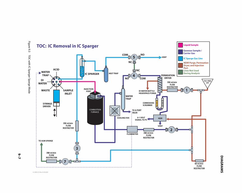
DIA
GR
AM
S
9–7
Figu
re 9.3TO
C w
ith IC
Sparg
er Sparg
e Mod
e

DIA
GR
AM
S
9–9
Figu
re 9.4TC
An
alysis Mod
e

DIA
GR
AM
S
9–1
1
Figu
re 9.5IC
An
alysis Mod
e

DIA
GR
AM
S
9–1
3
FOR FURNACE TO OPERATE.NOTE: MUST BE CONNECTED (SHORTED)
NOTE: VALVES BELOW ARE RATED 24 VDC WITH 12 VOLTS SUSTAINING VOLTAGE.
BLK
RED
YELYELVIO
ORG
GRNBLK
RED
(14-7622-086)
P7
(14-7674-10L)OR
(14-7621-086)
115 VAC / 60 HZ
AC NEUTRAL
(14-7674-10H)NDIR
(14-4383-028)
GROUND
NEUTRAL
LINE
GRN
WHT
BLK1
2
3
MODULEPOWER
1 +
NOTE 2:BLK 7 AC LINE
89
4
23
56
**
**
WHTGRN
BRN
GROUND-
BLK
(14-7621-086)
(14-7621-086)
WHT
GRN
BLK
FOR TIEPOINTJUMPERED ON CABLE
GROUND
NEUTRAL
1
3
2
GROUND
+12VCN41
2
+24V
-12V
+12V
NC111213
1098
(14-7624-090)SUPPLY
LINECN1
5
4
POWER
DGNDAGND
765432
+5V 1
CN2
FUSE 1
(14-7758-086)
J1
1
32
5
76
1098
4
78910
P16
1
34
2
56
P15
2
5
34
6
1
DB9/FEMALE
TO HOST PC7
59483
RX2
GROUND
RX3
261
TX3
(14-7105-086)
TO AUTOSAMPLER
5948
DB9/MALE
GROUND
+12V
37261
TX1
RX1
(14-7034-086)
REDBLKORGVIOYEL
GROU
ND
GROU
ND
NDIR
SIG
IN
GROUND
SHIE
LD
P24 1BL
K
2 3BR
N
RX3
TX3
RX2
TO BOTTOM MOST PINS.NOTE: 50 PIN CONNECTOR; ATTACH
TX1
+12V
GROUND
RX1
TOP VIEW P15
-12V
+5VGROUND
+12V1
2
(14-7150-034)
+24V 3
4
5
6
(14-7009-090)CPU BOARD
115 VAC 60 HZ CONFIGURATION
14-7629-050
3
SPARGERIC
P1
CN1
+12V
21 2CN
2
P2 1+1
2V
P3 1+1
2V
14-7629-050
1
DRYERPERM
14-7629-050
FURNACE
2
1+1
2V
P42CN
3P52
CN4
P621+1
2V CN5
21+1
2V CN6
14-7627-05014-7627-050NDIR/VENTFURNACE
4 5
GASIC
SW LINE
NEUTRAL
FURNACE(14-7640-000)
(14-7626-090)CONTROLLER
INPUT CNTRL (+)GRN
INPUT CNTRL (-)4
(14-7717-000)FAN
RED
BLK
BLK
AC OUTPUT
AC OUTPUT
S.S. RELAY(14-7682-051)
1
2
3
2345678BLK
WHT
REDBLKYELRED 1
LINE
NEUTRAL
OT1(+)OT1(-)S1(+)S2(-)
TEMP
(14-7620-086)
GROUND (SCREW)
LINE
SW LINE
TEMP SENSOR(14-7639-000)
BLK
GRN2
3
(14-7620-086) BLK 1
NOTE 1:
WHT
BLK
1
*
*3
4
2
4
3
2
1
OVER
100 VAC & 115 VAC CONFIGURATION
HEATER 1
HEATER 2
WHT
RED
YEL
RED
2 1
NOTE 4: FOR 100 VAC OPERATION INTERNAL MODIFICATIONS TO THE NDIR MUST BE MADE.
NOTE 3: REPRESENTS JUMPER LOCATED ON THE NDIR BLOCK FOR FREQUENCY OPTIONS.
NOTE 2: REPRESENTS JUMPERS LOCATED ON THE NDIR TERMINAL BLOCK FOR VOLTAGE OPTIONS.
NOTE 1: REPRESENTS JUMPERS LOCATED ON THE FURNACE TERMINAL BLOCK FOR VOLTAGE OPTIONS.
ALTERNATE VOLTAGE AND FREQUENCY CONFIGURATION
230 VAC 50 HZ CONFIGURATION CHANGES
230 VAC CONFIGURATION
BRN
(14-7011-052)PUMPER
WHTTX3 3
4
GROUND
RX3BLK
RED1
2
P29
RED 3
(14-7619-086)
BLK
WHTP3
2
1
(14-7617-086)
INTERLOCK
GROUND BLKP22
1
2
CN UV
+24V
P21
GRN2
1
(14-7617-086)
(14-7618-086)
YEL
4
3
2
14 PIN
GRN
*BLK
NOTE 1:
WHT
3344 SW LINE
2
11
2
NEUTRAL
FURNACE(14-7640-000)
14-7621-086
NOTE 3: *** 9
NOTE 2:BLK
4
23
WHTGRN
876**5
WHT
WHT
321+1
2V CN7
+10
REF
GROU
ND
P25 1 2O
RGO
RG
GRN
GRN
FLO
W S
IG4
FLO
W S
IG1
(14-7628-050)METER
14-7629-050
7ASM
SPARGE +10
REF
GROU
ND3 2
FLOW
14-7
758-
086
1BLK
100 VAC TAP TO
14-7
758-
086
MECHANICAL VIEW OF 410240 TRANSFORMER
GROUNDAC NEUTRAL
AC LINE
HEATER 1
HEATER 2
1BLK
PRIMARY
2
45
6
RED
WHT
YEL
RED
12
230 VAC / 50 HZ
-GROUNDAC NEUTRAL
AC LINE14-7621-086
**
WHT
***
**
BLK
NOTE 3:
NOTE 2:
4
9
78
65
GRN
BLKBRN
1-
32
+
SECONDARY
7BLK
8
10
11
12
100 VAC / 50 HZ
BLK
CHOPPER MOTOR
****NOTE 4:
****
1
2
4
4102406
5
SEE NOTE 4 FOR INTERNAL MODIFICATIONS REQUIRED
100 VAC 50 HZ CONFIGURATION CHANGES
(14-7674-30H) OR (14-7674-30L)
MAKE EXTERNAL CONNECTIONS AS SHOWN IN THE 100 VAC DIAGRAM.
REMOVE THE WIRE (ORIGINATING FROM THE EXTERIOR TERMINAL BLOCK PIN 6) FROM THE TRANSFORMER PIN 2 AND REATTACH TO PIN 1 OF THE TRANSFORMER AS SHOWN IN THE
TRANSFORMER PIN 6 AND REATTACH TO PIN 5 OF THE TRANSFORMER AS SHOWN IN THE REMOVE THE WIRE (ORIGINATING FROM THE EXTERIOR TERMINAL BLOCK PIN 7) FROM THE
50 HZ (JUMPER 8 TO 9). 60 HZ (NO JUMPER 8 TO 9).
(14-7674-20L)
(14-7674-20H)OR
NDIR
+
100 VAC DIAGRAM.
100 VAC DIAGRAM.
** *
NDIR
***
Figu
re 9.6A
po
llo 9000 W
iring
Diag
ram

DIAGRAMS
9–15
Figure 9.7 Apollo 9000 CPU Board

APPENDIX
A

A–3
APPENDIX A
A.1 Preventive Maintenance
The Apollo 9000 Consumables Kitincludes most items needed forpreventive maintenance.
Daily Maintenance Checks
The following components should bechecked on a daily basis:
• Carrier gas, 500+ psig from tank torun scheduled load.*
• Ample acid supply for load.*
• Replaced and ample DI watersupply for load.*
• Check chlorine scrubber to ensureample life for load.*
• Carrier gas flow rate (200 cc/min ±10%).
• Make sure 8-port valve thumb-screws are hand-tightened.
• Inspect and clean syringe, ifappropriate.
* Load = estimated amount of daily analysis
Weekly Maintenance Checks
The following components should bemaintained on a weekly basis:
Daily checks, plus:
• Clean IC sparger with soap andwater, if needed.
• Change reagents, if needed.
• Clean syringe.
Monthly Maintenance Checks
The following components should bemaintained on a monthly basis:
Daily and weekly checks, plus:
• Change corrosives scrubber.
• Inspect permeation dryer fordamage, water accumulation.
Copy and use the following Apollo9000 Maintenance Worksheets as achecklist in your daily analysis plans.

A–4
APPENDIX A
Apollo 9000 Maintenance Worksheet
Month __________ Year ________
Signature(s) ________________________________
________________________________
D=DailyW=WeeklyM=Monthly
Sat Sun Mon Tue Wed Thu Fri
D
W
M
D
W
M
D
W
M
D
W
M
D
W
M
Notes:
___________________________________________________________________
___________________________________________________________________
___________________________________________________________________
___________________________________________________________________
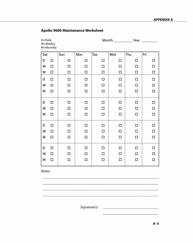
A–5
APPENDIX A
Apollo 9000 Maintenance Worksheet
Month __________ Year ________
Signature(s) ________________________________
________________________________
D=DailyW=WeeklyM=Monthly
Sat Sun Mon Tue Wed Thu Fri
D
W
M
D
W
M
D
W
M
D
W
M
D
W
M
Notes:
___________________________________________________________________
___________________________________________________________________
___________________________________________________________________
___________________________________________________________________

A–6
APPENDIX A
Apollo 9000 Maintenance Worksheet
Month __________ Year ________
Signature(s) ________________________________
________________________________
D=DailyW=WeeklyM=Monthly
Sat Sun Mon Tue Wed Thu Fri
D
W
M
D
W
M
D
W
M
D
W
M
D
W
M
Notes:
___________________________________________________________________
___________________________________________________________________
___________________________________________________________________
___________________________________________________________________

A–7
APPENDIX A
Apollo 9000 Maintenance Worksheet
Month __________ Year ________
Signature(s) ________________________________
________________________________
D=DailyW=WeeklyM=Monthly
Sat Sun Mon Tue Wed Thu Fri
D
W
M
D
W
M
D
W
M
D
W
M
D
W
M
Notes:
___________________________________________________________________
___________________________________________________________________
___________________________________________________________________
___________________________________________________________________

A–8
APPENDIX A
Apollo 9000 Maintenance Worksheet
Month __________ Year ________
Signature(s) ________________________________
________________________________
D=DailyW=WeeklyM=Monthly
Sat Sun Mon Tue Wed Thu Fri
D
W
M
D
W
M
D
W
M
D
W
M
D
W
M
Notes:
___________________________________________________________________
___________________________________________________________________
___________________________________________________________________
___________________________________________________________________

A–9
APPENDIX A
Apollo 9000 Maintenance Worksheet
Month __________ Year ________
Signature(s) ________________________________
________________________________
D=DailyW=WeeklyM=Monthly
Sat Sun Mon Tue Wed Thu Fri
D
W
M
D
W
M
D
W
M
D
W
M
D
W
M
Notes:
___________________________________________________________________
___________________________________________________________________
___________________________________________________________________
___________________________________________________________________

A–10
APPENDIX A
Apollo 9000 Maintenance Worksheet
Month __________ Year ________
Signature(s) ________________________________
________________________________
D=DailyW=WeeklyM=Monthly
Sat Sun Mon Tue Wed Thu Fri
D
W
M
D
W
M
D
W
M
D
W
M
D
W
M
Notes:
___________________________________________________________________
___________________________________________________________________
___________________________________________________________________
___________________________________________________________________

A–11
APPENDIX A
Apollo 9000 Maintenance Worksheet
Month __________ Year ________
Signature(s) ________________________________
________________________________
D=DailyW=WeeklyM=Monthly
Sat Sun Mon Tue Wed Thu Fri
D
W
M
D
W
M
D
W
M
D
W
M
D
W
M
Notes:
___________________________________________________________________
___________________________________________________________________
___________________________________________________________________
___________________________________________________________________

A–12
APPENDIX A
Apollo 9000 Maintenance Worksheet
Month __________ Year ________
Signature(s) ________________________________
________________________________
D=DailyW=WeeklyM=Monthly
Sat Sun Mon Tue Wed Thu Fri
D
W
M
D
W
M
D
W
M
D
W
M
D
W
M
Notes:
___________________________________________________________________
___________________________________________________________________
___________________________________________________________________
___________________________________________________________________

A–13
APPENDIX A
Apollo 9000 Maintenance Worksheet
Month __________ Year ________
Signature(s) ________________________________
________________________________
D=DailyW=WeeklyM=Monthly
Sat Sun Mon Tue Wed Thu Fri
D
W
M
D
W
M
D
W
M
D
W
M
D
W
M
Notes:
___________________________________________________________________
___________________________________________________________________
___________________________________________________________________
___________________________________________________________________
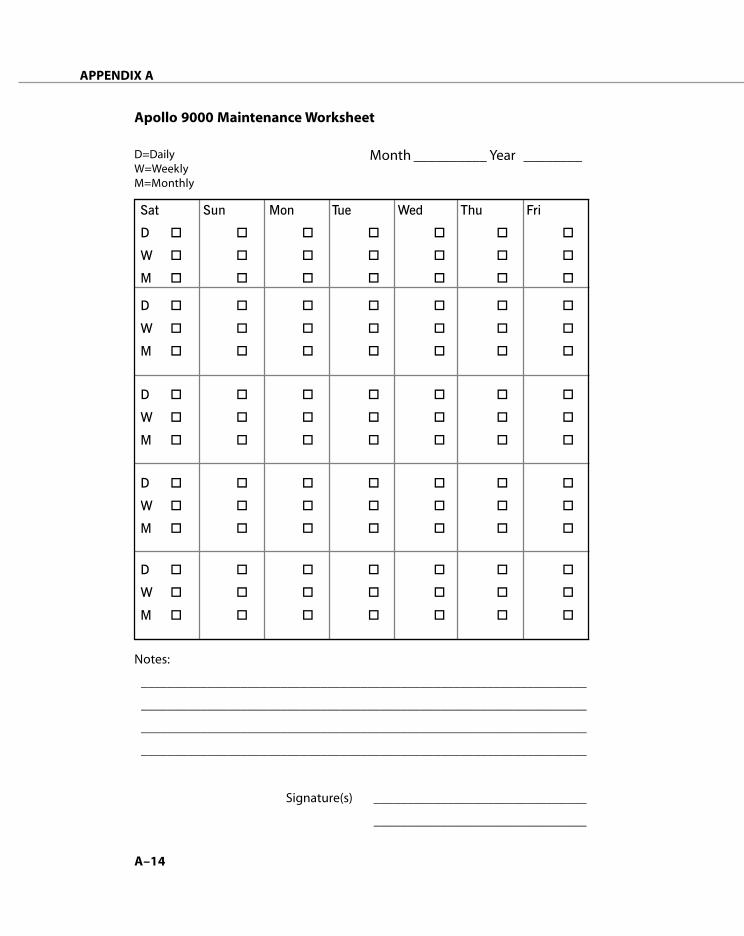
A–14
APPENDIX A
Apollo 9000 Maintenance Worksheet
Month __________ Year ________
Signature(s) ________________________________
________________________________
D=DailyW=WeeklyM=Monthly
Sat Sun Mon Tue Wed Thu Fri
D
W
M
D
W
M
D
W
M
D
W
M
D
W
M
Notes:
___________________________________________________________________
___________________________________________________________________
___________________________________________________________________
___________________________________________________________________

A–15
APPENDIX A
Apollo 9000 Maintenance Worksheet
Month __________ Year ________
Signature(s) ________________________________
________________________________
D=DailyW=WeeklyM=Monthly
Sat Sun Mon Tue Wed Thu Fri
D
W
M
D
W
M
D
W
M
D
W
M
D
W
M
Notes:
___________________________________________________________________
___________________________________________________________________
___________________________________________________________________
___________________________________________________________________

A–16
APPENDIX A
Apollo 9000 Maintenance Worksheet
Month __________ Year ________
Signature(s) ________________________________
________________________________
D=DailyW=WeeklyM=Monthly
Sat Sun Mon Tue Wed Thu Fri
D
W
M
D
W
M
D
W
M
D
W
M
D
W
M
Notes:
___________________________________________________________________
___________________________________________________________________
___________________________________________________________________
___________________________________________________________________

INDEX

iii
INDEX
Symbols
µgC 4-5, 4-12
A
AC power 7-11, 7-13, 7-14, 7-15Acid 2-10, 5-7, 7-9
Content, Samples with High 6-7reagent 5-5supply 4-16, 5-5, 7-3vial 4-16vial bracket 2-16
Active Calibration Curve 4-4, 4-6, 4-13
air bubbles 1-15Analysis 5-3
Methods, modifying 6-8range 3-5Results 4-7, 4-9, 4-14, 4-16, 5-4, 5-6Setup 4-8Time 1-4
Applications, special 6-3Anhydrous sodium carbonate 2-5AOAC 973.47 1-5Apollo 9000 1-3
dimensions 2-5software 1-4TOC Talk 2-21
Archive Data 3-10Archive Now 3-10archive utility 3-5area counts 4-9, 4-16Arm Locking Screw 2-13ASM (see Autosampler)ASTM D2579 1-5Auto
Shutdown 3-5Shutdown With Furnace Off 3-5
Auto-dilution method 1-5Auto-rinsing 1-5
AutomaticArchive 3-5, 3-10blank subtraction 1-5shutdown/standby 1-5syringe injection 1-5Wake-up 1-5
Autosampler 1-5, 2-12Analysis Setup 5-7Diagnostics 3-8Needle 7-5rack 2-17sparge line 1-13Sparge Option 3-4, 4-16, 5-6, 5-7vial position 4-14
Auxiliary 3-6
B
baseline 3-4Baud Rate 2-13blank 4-3
methods 4-3values 1-5
C
Cal. Factor 3-9calculated value 4-5, 4-12calculation of PPM C 4-9Calibration 1-5, 3-5, 3-9, 4-3, 4-4, 4-
10blank 4-4Curve 4-3, 4-9, 4-10, 4-13, 4-16, 5-4data 1-4errors 3-5factor 4-4points 4-4, 4-10Setup 4-5, 4-12, 4-13Slope 4-4standards 4-3verification 4-3
Carbon 1-4content 4-3dioxide 1-12

iv
INDEX
Carrier gas 1-4, 1-11, 7-22, 7-25fitting 7-6lines 7-26tubing 2-4
Catalyst 2-18, 2-22, 7-16catalyst 1-10, 2-19, 7-17Choose Range 4-8, 4-14Cleaning Validation 1-5CO
2 1-3, 1-4, 1-10, 1-12
Com 1 2-11Com 2 2-11Combustion
Furnace 1-3, 1-4, 1-10, 1-13, 2-20, 3-4, 3-5, 3-6, 3-9, 7-4, 7-6, 7-16, 7-24Tube 2-17—20, 2-22, 3-4, 3-6, 7-6, 7-16, 7-17
Communications 3-9, 7-12, 7-13Diagnostics 3-9port 3-9
compressed air 2-4Concentration (ppm C) 4-5, 4-12, 4-
13condensor coil 1-11Condition Catalyst 2-22Configure Instrument 5-3, 5-6Connections 2-7, 2-10Corrosives Scrubber 1-3, 1-11, 7-3, 7-
24, 7-25, 7-26CPU Board 9-8Current Positions (mm) 3-8Curve 4-13
D
DataArchive 3-10files 3-10Handling 1-5
Detailed Report 5-5, 5-8Detection and Results 1-4Detector 1-4, 7-25
Output 4-4signal 5-3
DI Water 2-4, 2-10, 2-22, 4-16, 5-5, 7-3, 7-9, 7-12
Diagnostics 3-6, 3-8, 3-9, 7-6distilled water (see DI Water)drain tubing 2-17Drinking / Surface water 1-5
E
Electrical 1-7Connections 2-11outlet 2-4
EPA 415.1 and 9060A 1-5
F
flammable gas 2-10flow diagram 7-22Flow
meter 3-9, 7-15path 7-22, 7-25rate 7-3rate monitoring 1-5restrictors 1-13, 7-24, 7-26
Frequency 1-6Furnace 2-18, 2-20, 3-4, 3-9, 4-3, 7-
17carrier gas 7-24flow 7-26Gas To either Vent, NDIR 3-6Gas to vent 7-23Injection Port 1-3, 7-8Power 3-6
Fuses 1-6, 2-12
G
Gas 2-3and water connections 2-7flow 5-3, 7-4Flow Rate (cc/min) 3-4generator 2-4In 2-10Input 3-6Output 3-6permeation tube 1-12Pressure 1-6Supply 1-6to IC Sparger 7-23

v
INDEX
gas/liquid separator 1-11
H
halogen 1-11removal 1-3
humidity 2-3Hydrochloric Acid 6-4hydrogen 2-10
I
IC 1-3, 1-4, 1-10, 1-15, 1-19by Acidification and Sparge 1-4calibration 2-5flow 7-24Gas 7-23To either NDIR,Vent 3-6sparge methods 1-5
IC Sparger 1-10, 1-13, 3-4, 3-6, 7-3, 7-10, 7-23, 7-24, 7-25, 7-26Carrier Gas 7-25, 7-26output 3-6
infrared energy 1-12Initialize 7-9, 7-10, 7-12injection port 2-20, 7-6, 7-16, 7-
17, 7-24Injection Volume 1-4Inorganic Carbon 1-3, 1-10, 1-15, 1-
19High Fraction of 6-8
InstrumentDiagnostics 3-6Name 2-21, 3-3Setup 3-3Setup/Status 2-21, 3-3, 5-3, 5-6
integrated peak 4-9, 4-16Intercept 4-4Interface Cable 2-13ISO 8245 1-5
K
KHP, KC8H5O4 2-5
L
Leak Checking 7-22after the Mist Trap 7-26after the Water Trap 7-24before the Water Trap 7-24IC Sparger 7-23
LED display 1-13linear
equation 4-3fit 4-3
Liquid Handling 1-5low-level
Carbon 6-4methods 4-3
M
Maintenance 7-3Checks 7-3worksheets 7-3
ManualArchive 3-10Movement 3-8Syringe 1-5
Mass (µgC) 4-4Max. Integration Time (min.) 3-4measured carbon 4-3Measurements 1-4Memory 2-5Method 1-5, 5-4
ID 2-22, 4-5, 4-6, 4-8, 4-12, 4-13, 5-4, 5-7, 7-9Parameters 6-9Setup 1-5
Mist Trap 1-11, 7-25, 7-26, 7-27Mode 5-4
Status 3-3Moisture
Control System 1-11removal 1-3
Move To Vial 3-8Multi-point 1-5
vi
INDEX
N
NDIR 1-4, 1-12, 1-13, 2-3, 2-11, 3-4, 4-7, 4-14, 7-22, 7-23, 7-25, 7-27Detector 1-3, 2-11flow 7-23mV output 3-3purge gas 7-26
Near line monitoring 1-5Needle 7-5
holder 2-15Nitric Acid 6-4non-linear signal 1-4Nondispersive Infrared (see NDIR)nonpurgeable organic carbon 1-3NPOC 1-3
O
Operating Modes 1-15Operator Name 2-21, 3-3Options 2-21, 3-4organic
carbon levels 1-3halide levels 1-3
Out of Calibration 3-5Outlier 3-4
deletion 1-5, 3-4Over Range 3-5Oxidation by Combustion 1-4
P
Particulate Kit 3-4particulate requirements 1-5Particulated Samples 6-5parts-per-million (ppm) 1-4Password 3-11
Restriction Access 3-11Setup 3-11
PCB board 7-13, 7-14, 7-15Permeation
Dryer 1-11, 7-3, 7-23, 7-24Tube 1-3, 1-11, 1-13
Phosphoric Acid 2-4, 2-10, 6-4Pneumatic Connections 2-7
POC 1-3, 1-10Port
A 2-10, 5-5B 7-10D 2-22, 5-5G 2-10, 4-16, 5-5, 7-8
Pos 2-22, 4-14Position
4 and 5 2-1611 2-10, 4-16, 5-711 and 12 2-16
potassium acid phthalate 2-5Power 1-6, 2-4
Entry Module 7-15requirements 2-11Supply 2-17, 7-14
Preferences 2-21, 3-4pressure 2-4, 3-6
regulator 7-26preventive maintenance 7-3Print
Data Report 3-5Data Report after Each Sample Set3-5, 5-6
Priority samples 1-5purge 1-13purgeable organic carbon 1-3, 1-10
Q
quartz 2-18combustion tube 1-10wool 7-16
R
r2 4-10rack 2-17, 3-8
Selection 1-6Style 3-8
Range 1-4, 4-3errors 3-5
Rawcounts 4-3Data 4-4
Ready 2-21, 5-3, 5-6Mode 3-4

vii
INDEX
Reagent 2-4, 4-3, 7-3Contribution 4-4
Recalc 1-5, 4-10Recalculation (see Recalc)Repetitive Sampling 3-4Reps 4-8, 5-5, 5-7response factor 4-3Restricted Access 3-11result 4-9Review Analysis Results 4-4, 4-9, 4-16Rinse 1-6
Station 2-16, 2-17Water 4-3
RS-232 2-11, 2-13, 7-11connections 7-11Interface Cable 2-13, 7-11
RSD 1-4, 5-5, 5-8Run 4-7, 4-14, 5-4, 5-6
Screens 4-7, 4-14
S
Safety 1-8, 7-3references 1-8
Salt Content, Samples with High 6-6Sample 1-5, 4-3, 5-4, 5-7
Analysis 2-22, 4-7, 4-8, 4-14, 4-16, 5-3, 5-4, 5-5, 5-6, 5-7, 5-8blank 4-3concentration 1-4Delivery 1-15dilution 1-10ID 4-7, 4-14, 5-4inlet line 7-25Introduction 1-5, 1-15, 2-21, 3-4, 5-6Needle 2-15Preservation for TOC 6-3repetitions 5-7run 4-3, 5-5, 5-8set 3-5Setup 2-22, 4-7, 4-8, 4-14, 5-4, 5-6, 5-7Tray 2-17Type 2-22, 4-3, 4-6, 4-8, 4-13, 4-14, 5-4, 5-7
Scrubber 1-11Select Calibrator 4-8septum 7-5
piercing 1-6Set
Active Calibration Curve 4-4, 4-6, 4-13Home 7-9, 7-10, 7-12point 1-13, 7-18
setup 2-3Standard Calibration Analysis 4-7, 4-14Sample 5-3Standard Calibration Analysis 4-4
Sleep Mode 2-3, 3-4Slope 4-3, 4-4Sludges 6-7sodium hydroxide solution 2-22Solids and Sludges 6-7Sparge Option 3-4Sparger 1-3Stabilize Baseline Time (sec.) 3-4Standard 4-3, 4-6, 4-13
analysis 4-14, 4-16analysis rep 4-9Calibration 4-3, 4-4, 4-6, 4-10, 4-12, 4-14concentration 4-10deviation 5-5, 5-8ID 4-5, 4-8, 4-12Method 5310B 1-5run 4-9, 4-16
Standards 2-5Standby 2-3, 3-4, 3-5, 3-12Start 5-5, 5-8
Run 4-7, 4-14, 5-3Standard Calibration Analysis Run4-4, 4-16
status mode 3-4Stirring Option 1-5Strip Chart 4-7, 4-14, 5-4, 5-6STS-8000 Autosampler 1-6, 2-5, 1-14

viii
INDEX
Syringe 1-3, 1-15, 7-8, 7-9, 7-10, 7-11assembly 7-11Diagnostics 7-8, 7-10, 7-11Driver 1-5, 1-9, 7-8, 7-10, 7-11plunger 7-12
System 2-21, 3-4Calibration 4-3status 3-4
T
TC 1-3, 1-4, 1-15methods 4-3
TC-IC 1-15TC/TOC standard 2-5Temperature Controller 1-13, 2-22Time vs. Millivolts 4-7, 4-14tin 1-11
and copper granules 1-11TOC 1-3, 1-4, 1-15, 3-4
analysis 1-3, 1-10Analysis Time 1-5Curve 4-6Gas Generator 1-6, 2-3Results 5-6sample analysis procedure 5-3Standard 4-8
TOC Talk 1-4, 2-22, 3-3, 3-12, 7-5TOC-free carrier gas 2-7Total Carbon 1-3, 1-15Total Carbon Minus Inorganic Carbon
1-15Total Organic Carbon (see TOC)Troubleshooting 7-22Tubing 2-4, 2-8
connections 2-8tutorial 5-3two-stage regulator 2-7
U
ultra-pure water 4-3User Interface 1-4USP 643 1-5Utility Requirements 1-6, 2-3, 6-3
V
Valves 3-6, 7-24, 7-27Control 3-6mounting plate 7-16
Vialnumber 2-22Position 1 5-7
Voltage 1-6
W
Wakeup 3-12Schedule 3-12
Wastebottle 2-5water 1-3, 1-5, 6-7
Wateraccumulation 7-3Contribution 4-4Trap 1-3, 1-11, 1-12, 2-22, 3-6, 7-24trap flow 7-22
X
XYZ robot 1-6, 1-14
Y
y-intercept 4-3