APM Transapm.ru/downloads/documents/eng/apm_trans.pdf · external and internal spur gearing with...
55
APM Trans User's Guide
Transcript of APM Transapm.ru/downloads/documents/eng/apm_trans.pdf · external and internal spur gearing with...
APM Trans User's Guide
APM Trans The system for mechanical transmission calculation Version 9.1
User's Guide Research and software development center APM Ltd., Korolev-Center, box 58, Moscow region,
Russia 141070.

Copyright 19892006 by Research and Software Development Center APM Ltd. All rights
reserved. All APM products are trademarks and registered trademarks of APM Ltd. Other brand and product names are trademarks and registered trademarks of their respective holders.
Printed in Russia.

1 Introduction
Introduction
APM Trans-what is it ?
APM Trans is the system for calculation and design of mechanical transmission developed by
the Research and Software Development Center APM Ltd. Using APM Trans you can calculate the following:
General geometry parameters •Forces, acting in the meshing •Longevity •Maximum allowable load ••Control parameters
The system allows to calculate eight the most widely used types of transmission:
external and internal spur gearing with involute teeth •helical gearings •herring bone gearings ••bevel gearing with standard involute
tworm gearings eeth and circular teeth •flat belt transmissions •V-belt transmission ••chain transmission
With APM Trans you can generate the working drawings of the transmission in the DXF format
and APM Graph file format.
Hardware and software requirements
Hardware minimum: CPU 600 MHz, RAM 64 Mb. Software MS Windows 2000, XP.
What's in this manual
Introduction (this section) tells you what APM Trans is in general, what parameters and what types of transmission could be calculated. You will know the requirements to hardware and system software.
APM Trans User’s Guide 2
Chapter 1, Problems and results contains description of the problems solved with APM
Trans. All the calculated parameters and initial data are listed. The standards used for transmission calculation are described.
Chapter 2, How to work with APM Trans leads you through a sample session in order to
demonstrate main operations -- how to install and start the program, enter initial data, perform calculations, browse the results, specify working drawing.
Chapter 3, APM Trans in answers and questions contains answers to common questions
that may arise when you work with APM Trans. Chapter 4, Data base and archive files summarizes the local data base features -- structure,
using, updating. File of system initialization is described as well. Chapter 5, APM Trans environment describes the main elements of APM Trans environment
-- menus, dialog boxes and controls, information window’s. Chapter 5, Command reference contains complete description of all commands of the main
menu and popup menus.
Typefaces used in this book To facilitate reading and avoid misunderstanding we use a set of typefaces. Their uses are as
follows. a:\setup SETUP.EXE Help Results
This typeface represents text as it appears or anything you must type (for example, a:\setup to start installation program). We use all capital letters for the names of files and keys. APM Trans command names are shown in boldface. Italics is used for the names of dialog boxes and controls
How to contact APM
To contact APM you can use one of the following ways: Phone +7(495) 585-06-11 (fax), 514-84-19 (Moscow).
Write a letter and send it to
Research and Software Development Center APM LTD Korolev-Center, box 58 Moscow Region 141070 Russia
E-mail: [email protected] www.apmwm.com

3 Chapter 1 Problems and results
Chapter 1 Problems and results
PM Trans is intended for mechanical transmission calculation and design. It allows: A• to specify transmission design to perform all the calculations required •• to obtain working drawings of transmission
Transmission types
APM Trans allows calculating transmissions of the following types:
Fig 1.1 Types of transmission calculated with APM Trans.
Calculation types
Using APM Trans you can perform the following types of calculations:
APM Trans User`s Guide
transmission design • • load capacity calculation
• design with constraints Transmission design With this type of calculation you define gear dimensions based on required power.
Basic initial data for design calculation are torque transmited by transmission, revolution of driven shaft, type of loading, required longevity. APM Trans calculates geometry of transmission based on criteria of bending and pitting endurance.
You can impose the constraints on the dimensions of the transmission, for example you can design the transmission with given centre distance, etc.
Load capacity calculation
With this type of calculation you can determine the load capacity of the given
transmission (with known dimensions, material, thermal treatment, etc.). Two subtypes of calculation are realized in the system:
• Maximum transmitted torque checking • Longevity of transmission with given loads checking Extra option is available for cylindrical gears namely required summary addendum
modification calculation by given center distance. Design with constraints It is possible to place additional constraints on designed gear. For example gear with
standard center distance or required helix angle, module, etc. can be designed. Enter additional data to define constraints. Use Additional data dialog that is invoked by “More…” button from main geometry data dialog.
Initial data
All initial data in APM Trans are divided into two groups: General data and Additional
data. General data are the minimum data required to perform calculations of given type. Additional data are used to impose constraints to designed transmission and are optional.
Both general and additional data for each transmission type are listed below.
Cylindrical gearings. Design calculation. General data for design calculation 1. Torque at the output shaft 2. Rotational speed of the output shaft 3. Gear ratio 4. Required lifetime 5. Number of meshing of each wheel per one revolution of drive wheel 6. Location of the wheel at the shaft (symmetrical, non-symmetrical, cantilever) 7. Thermal treatment for each wheel (martempering, hardening, carburizing,
carbonitriding, nitriding) 8. Operation mode (constant, heavy, mean, mean-probable, light, very light) Additional data for design calculation 1. Centre distance
5 Chapter 1 Problems and results
2. Wheel facewidth ratio (relative to the centre distance) 3. Module 4. Helix angle 5. Addendum modification coefficient for each wheel 6. Average hardness of teeth surface. If not defined by user APM Trans assumes
average hardness specified by given type of thermal treatment. 7. Average hardness of teeth core. If not defined by user APM Trans assumes average
hardness specified by given type of thermal treatment. 8. Teeth number of each wheel 9. Reversible or nonreversible transmission. Nonreversible transmission assumed by
default. 10. Standard center distance flag. If it is switched on center distance is selected from
R40 row. 11. Pinion material. It is selected from gear material database. If it is not specified
allowable stresses are calculated according to selected thermal treatment and hardness. 12. Wheel material. It is selected from gear material database. If it is not specified
allowable stresses are calculated according to selected thermal treatment and hardness.
Cylindrical gearings. Checking calculation. General data for checking calculation
1. Module. 2. Helix angle (for herringbone and helical gearing only). 3. Teeth number of each wheel. 4. Width of each wheel. 5. Addendum modification coefficient of each wheel. 6. Output torque (for longevity checking calculation) [Nm]. 7. Output revolution [rpm]. 8. Required longevity (for torque checking calculation) [H]. 9. Number of engagements of each wheel. 10. Thermal treatment of each wheel. 11. Working condition (operation mode – invariable, heavy, mean equiprobable,
mean normal, etc.). 12. Fastening of drive wheel.
Additional data for checking calculation
1. Gear manufacturing accuracy. 2. Average surface hardness. Average hardness is defined by thermal treatment
by default. 3. Average hardness of teeth core. Average hardness is defined by thermal
treatment by default. 4. Pinion material. It is selected from gear material database. If it is not specified
allowable stresses are calculated according to selected thermal treatment and hardness.
5. Wheel material. It is selected from gear material database. If it is not specified allowable stresses are calculated according to selected thermal treatment and hardness.
6. Reversible or nonreversible transmission. Nonreversible transmission assumed by default.
7. Roll diameter. It is used in roller test. 8. Teeth number for common normal length test 9. Center distance. It is used for summary addendum modification calculation to
get specified center distance.
Bevel gearings. Design calculation. General data for design calculation
APM Trans User`s Guide
1. Torque at the output shaft 2. Rotational speed of the output shaft 3. Gear ratio 4. Required lifetime 5. Thermal treatment for each wheel (see cylindrical gearings) 6. Operation mode (see cylindrical gearings) Additional data for design calculation
1. Helix angle. 2. Facewidth of wheel 3. External module at outer tooth end 4. Average hardness of teeth surface. If not defined by user APM Trans assumes
average hardness specified by given type of thermal treatment. 5. Average hardness of teeth core. If not defined by user APM Trans assumes average
hardness specified by given type of thermal treatment. 6. Type of drive shaft supporting (roll bearings or ball bearings) 7. Reversible or nonreversible transmission. Nonreversible transmission assumed by
default. 8. Tooth shape (for spiral bevel gear). 9. Addendum modification coefficient of pinion. 10. Coefficient of pinion teeth thickness change 11. Gear-shaping cutter head diameter. If not defined it is selected from APM Mechanical
database. See Gear-shaping cutter head below. 12. Point width of gear-shaping cutter. If not defined it is selected from APM Mechanical
database. See Gear-shaping cutter head below. 13. Pinion material. It is selected from gear material database. If it is not specified
allowable stresses are calculated according to selected thermal treatment and hardness.
14. Wheel material. It is selected from gear material database. If it is not specified allowable stresses are calculated according to selected thermal treatment and hardness.
Bevel gearings. Checking calculation.
General data for checking calculation
1. Helix Angle. 2. Teeth number of each wheel. 3. Average facewidth of wheel. 4. Outer Module. 5. Addendum Modification Coefficient of each wheel. 6. Output torque (for longevity checking calculation) [Nm]. 7. Output Revolution 8. Required longevity 9. Thermal treatment for each wheel 10. Operation mode
Additional data for checking calculation
1. Average hardness of teeth surface. If not defined by user APM Trans assumes average hardness specified by given type of thermal treatment.
2. Average hardness of teeth core. If not defined by user APM Trans assumes average hardness specified by given type of thermal treatment.
3. Type of drive shaft supporting (roll bearings or ball bearings). 4. Tooth shape. 5. Reversal or not reversal transmission. Not reversal transmission assumed by default.
7 Chapter 1 Problems and results
6. Gear accuracy. 7. Coefficient of pinion teeth thickness change 8. Gear-shaping cutter head diameter. If not defined it is selected from APM Mechanical
database. See Gear-shaping cutter head below. 9. Point width of gear-shaping cutter. If not defined it is selected from APM Mechanical
database. See Gear-shaping cutter head below. 10. Pinion material. It is selected from gear material database. If it is not specified
allowable stresses are calculated according to selected thermal treatment and hardness.
11. Wheel material. It is selected from gear material database. If it is not specified allowable stresses are calculated according to selected thermal treatment and hardness.
Worm gearings. Design calculation.
General data for design calculation 1. Torque at the output shaft 2. Rotational speed of the output shaft 3. Gear ratio 4. Required lifetime 5. Material of the worm wheel rim (tin bronze, tinless bronze, cast iron) 6. Operation mode (see cylindrical gearings) Additional data for design calculation
1. Module 2. Diameter coefficient. Worm diameter coefficient is numerically equal to ratio of
worm reference diameter to module. 3. Center distance 4. Wheel facewidth coefficient 5. Number of worm threads 6. Coefficient of worm coil effective thickness. 7. Select worm from database flag. Worm is selected from APM Mechanical
database according to current selected standard if this flag is switched on. Database path for worm table: Standards – Parts – Transmissions – Transmission types – Worms.
Worm gearings. Checking calculation.
General data for checking calculation
1. Module 2. Coefficient of worm diameter 3. Addendum modification coefficient 4. Number of worm threads 5. Number of wheel teeth 6. Output torque 7. Output revolution 8. Required longevity 9. Aluminium in alloy presence 10. Operation mode (see cylindrical gearings)
Additional data checking calculation
1. Heat-Transfer Factor 2. Bending Safety Factor 3. Yield point of Wheel Material 4. Breaking Point of Wheel Material
APM Trans User`s Guide
5. Coefficient of worm coil effective thickness. 6. Fan ability flag
Chain transmission. Design calculation.
General data for design calculation 1. Torque at the output shaft 2. Rotational speed of the output shaft 3. Gear ratio 4. Required lifetime 5. Sprocket profile (convexo-concave, rectilinear) 6. Transmission loading type (smooth, quiet, with light shocks, with medium shocks,
with heavy shocks, vibrational) 7. The type of the chain used in transmission 8. Lubrication type (without lubrication, periodical, non-periodical, intra-hinge, oil bath
lubrication, spraying, circulating, drop-feed lubrication) Additional data for design calculation
1. Teeth number of each wheel 2. Centre distance
Chain transmission. Checking calculation.
General data for checking calculation 1. Input revolution [rpm]. 2. Required longevity. 3. Center distance. 4. Sprocket teeth number of each star. 5. Sprocket profile type (convexo-concave and rectilinear). 6. Lubrication type (without lubrication, periodical, nonperiodical, intrahinge, by oil
bath, by spraying, circulational, drop-feed). 7. The type of transmission loading (smooth, quiet, with light shocks, with medium
shocks, with heavy shocks, vibrations).
Belt transmission. Design calculation. General data for design calculation 1. Transmitted power 2. Rotational speed of input shaft 3. Gear ratio 4. Dynamics factor 5. Type of mechanism for belt tension control (for flat belt transmissions only) Additional data for design calculation 1. Center distance (in the range of standard belt lengths). 2. The slope of the transmission axis to the horizon (for flat belt transmission only) 3. Maximum number of the belts in the transmission (for V-belt transmissions only).
Should not exceed 8.
Belt transmission. Checking calculation.
9 Chapter 1 Problems and results
General data for checking calculation
• Rotational speed of the output shaft [rpm] • Driving Pulley Diameter [mm] • Driven Pulley Diameter [mm] • Belt length [mm] • Belt thickness [mm] (only for flat belt transmission) • Belt tape width [mm] (only for flat belt transmission) • Angle between center distance line and horizontal [deg] (only for flat belt
transmission) • Safety factor • Belts number (only for V – belt transmission) • Belt cross section (only for V – belt transmission) • Type of transmission adjustment (only for flat belt transmission)
Materials and Thermal treatment
Mechanical properties of gear materials are defined basically by their thermal
treatment. Thermal treatment is used to increase load-carrying capacity of the wheels. Four common types of thermal treatment are considered in APM Trans. Averaged allowable stresses depend on gear hardness according to selected calculation standard.
This dependence for GOST is represented below as an example.
Type Hardness σh0 σ f 0 σhmax σ f max 1 – Martempering 27.0 20*HRC+70 18*HRC 48.4*HRC 27.4*HRC 2 – Hardening 50.0 17*HRC+200 600 40*HRC 1320 3 - Caburizing 59.0 23*HRC 820 40*HRC 1300 4 - Nitriding
60.0 1050 684 35*HRC 1000
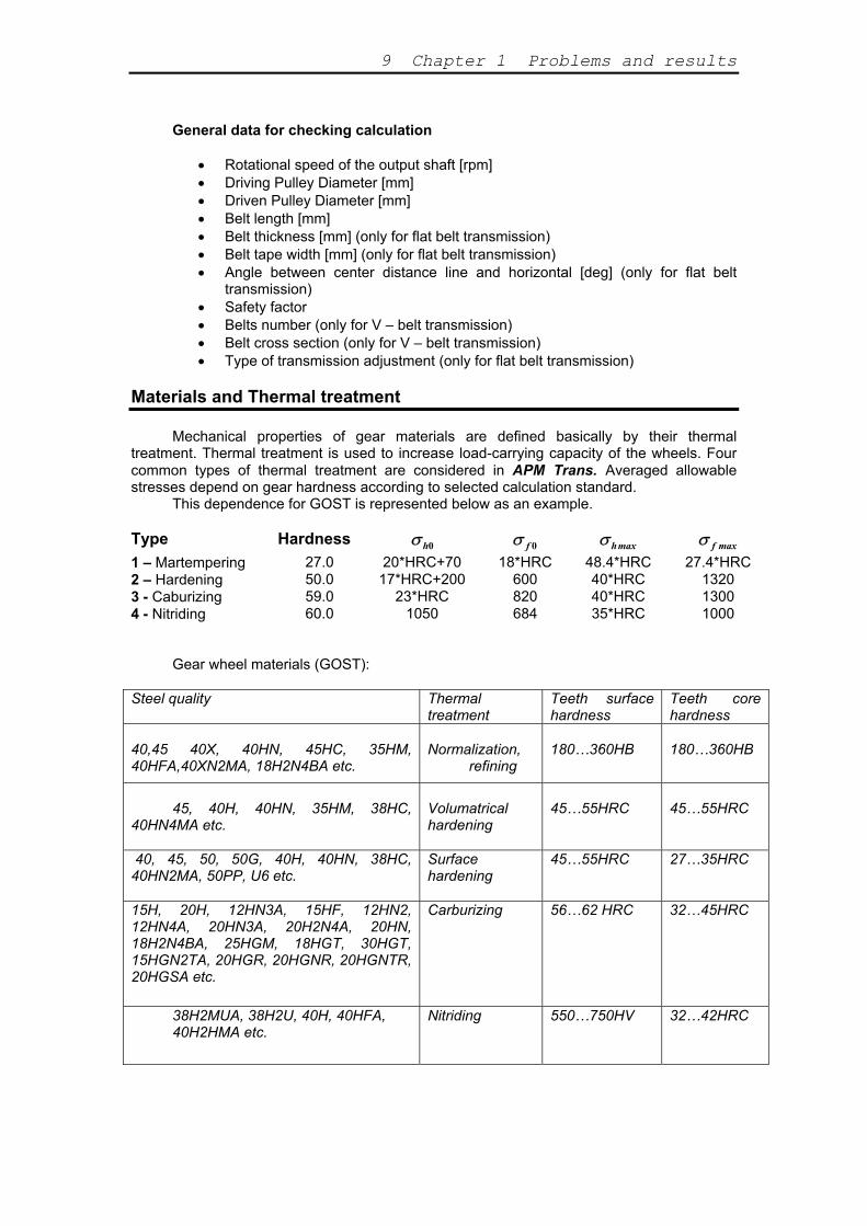
Gear wheel materials (GOST):
Steel quality Thermal treatment
Teeth surface hardness
Teeth core hardness
40,45 40X, 40HN, 45HC, 35HM, 40HFA,40XN2MA, 18H2N4BA etc.
Normalization,
refining
180…360HB
180…360HB
45, 40H, 40HN, 35HM, 38HC,
40HN4MA etc.
Volumatrical hardening
45…55HRC
45…55HRC
40, 45, 50, 50G, 40H, 40HN, 38HC, 40HN2MA, 50PP, U6 etc.
Surface hardening
45…55HRC 27…35HRC
15H, 20H, 12HN3A, 15HF, 12HN2, 12HN4A, 20HN3A, 20H2N4A, 20HN, 18H2N4BA, 25HGM, 18HGT, 30HGT, 15HGN2TA, 20HGR, 20HGNR, 20HGNTR, 20HGSA etc.
Carburizing 56…62 HRC 32…45HRC
38H2MUA, 38H2U, 40H, 40HFA, 40H2HMA etc.
Nitriding 550…750HV 32…42HRC
APM Trans User`s Guide
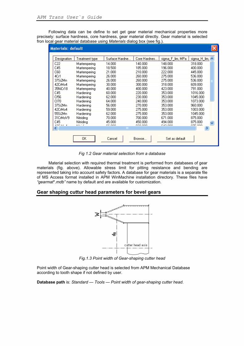
Following data can be define to set get gear material mechanical properties more precisely: surface hardness, core hardness, gear material directly. Gear material is selected fron local gear material database using Materials dialog box (see fig.).
Fig 1.2 Gear material selection from a database
Material selection with required thermal treatment is performed from databases of gear
materials (fig. above). Allowable stress limit for pitting resistance and bending are represented taking into account safety factors. A database for gear materials is a separate file of MS Access format installed in APM WinMachine installation directory. These files have “gearmat*.mdb” name by default and are available for customization.
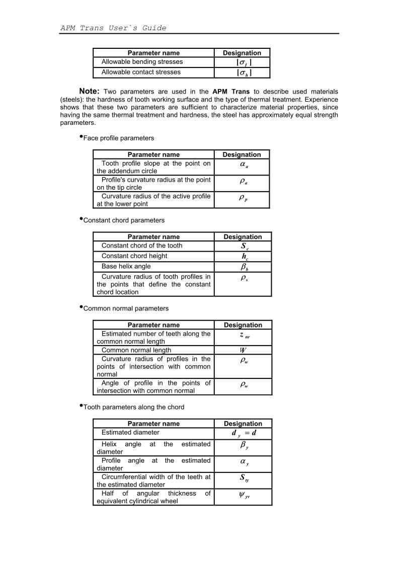
Gear shaping cuttur head parameters for bevel gears
Fig.1.3 Point width of Gear-shaping cutter head
Point width of Gear-shaping cutter head is selected from APM Mechanical Database according to tooth shape if not defined by user. Database path is: Standard — Tools — Point width of gear-shaping cutter head.

11 Chapter 1 Problems and results
Fig.1.4 Point width of Gear-shaping cutter head items from database.
Results APM Trans allows to calculate the following parameters: Cylindrical gearings: •General geometry parameters:
Parameter name Designation Centre distance Aw Module M Number of teeth Z Helix angle β Addendum modification coefficient x Reference diameter D Pitch diameter d w Base diameter d b Tip diameter d a Root diameter d f Tooth height h Facewidth of wheel Bw
•The forces acting in the transmission
Parameter name Designation Axial force Fa Radial force Fr Tangential force Ft Arm of the resultant force R The distance between wheel side
and force point L
•Used material parameters
APM Trans User`s Guide
Parameter name Designation Allowable bending stresses [ ]σ f Allowable contact stresses [ ]σ h
Note: Two parameters are used in the APM Trans to describe used materials
(steels): the hardness of tooth working surface and the type of thermal treatment. Experience shows that these two parameters are sufficient to characterize material properties, since having the same thermal treatment and hardness, the steel has approximately equal strength parameters.
•Face profile parameters
Parameter name Designation Tooth profile slope at the point on
the addendum circle α a
Profile's curvature radius at the point on the tip circle
ρa
Curvature radius of the active profile at the lower point
ρ p
•Constant chord parameters
Parameter name Designation Constant chord of the tooth S c Constant chord height hc Base helix angle βb Curvature radius of tooth profiles in
the points that define the constant chord location
ρs
•Common normal parameters
Parameter name Designation Estimated number of teeth along the
common normal length z nr
Common normal length W Curvature radius of profiles in the
points of intersection with common normal
ρw
Angle of profile in the points of intersection with common normal
ρw
•Tooth parameters along the chord
Parameter name Designation Estimated diameter d dy =
Helix angle at the estimated diameter
β y
Profile angle at the estimated diameter
α y
Circumferential width of the teeth at the estimated diameter
Sty
Half of angular thickness of equivalent cylindrical wheel
ψ yv
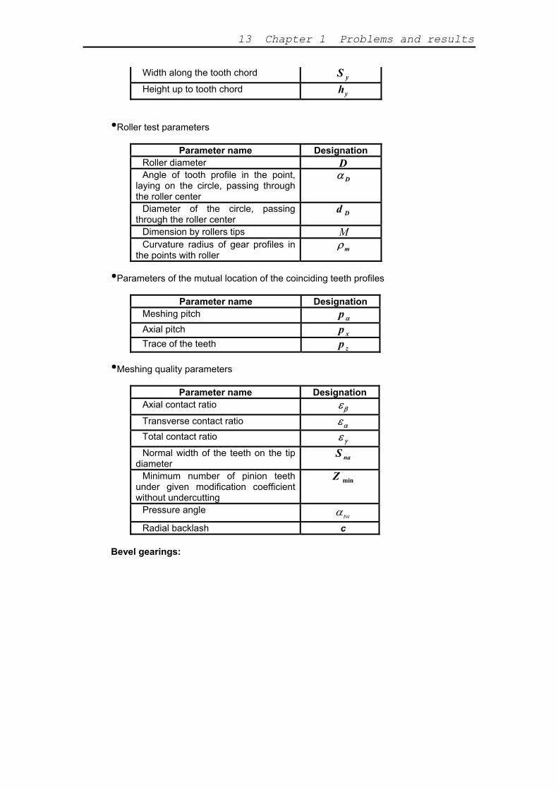
13 Chapter 1 Problems and results
Width along the tooth chord S y
Height up to tooth chord hy
•Roller test parameters
Parameter name Designation Roller diameter D Angle of tooth profile in the point,
laying on the circle, passing through the roller center
α D
Diameter of the circle, passing through the roller center
d D
Dimension by rollers tips M Curvature radius of gear profiles in
the points with roller ρm
•Parameters of the mutual location of the coinciding teeth profiles
Parameter name Designation Meshing pitch p α Axial pitch p x Trace of the teeth p z
•Meshing quality parameters
Parameter name Designation Axial contact ratio εβ
Transverse contact ratio εα Total contact ratio ε γ
Normal width of the teeth on the tip diameter
S na
Minimum number of pinion teeth under given modification coefficient without undercutting
Z min
Pressure angle twα
Radial backlash c Bevel gearings:
APM Trans User`s Guide
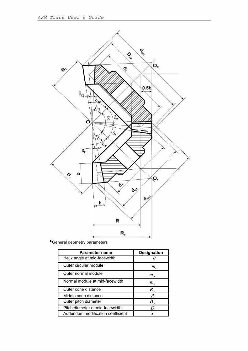
•General geometry parameters
Parameter name Designation Helix angle at mid-facewidth β Outer circular module
em
Outer normal module mne Normal module at mid-facewidth
nm
Outer cone distance Re Middle cone distance R Outer pitch diameter De Pitch diameter at mid-facewidth D Addendum modification coefficient x
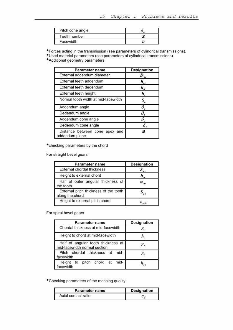
15 Chapter 1 Problems and results
Pitch cone angle δw Teeth number Z Facewidth b
Forces acting in the transmission (see parameters of cylindrical transmissions). •Used material parameters (see parameters of cylindrical transmissions). ••Additional geometry parameters
Parameter name Designation
External addendum diameter Dae External teeth addendum hae External teeth dedendum hfe External teeth height he Normal tooth width at mid-facewidth
nS
Addendum angle θa Dedendum angle θ f Addendum cone angle δ a Dedendum cone angle δ f Distance between cone apex and
addendum plane B
•checking parameters by the chord For straight bevel gears
Parameter name Designation External chordal thickness S ce Height to external chord hce Half of outer angular thickness of
the tooth ψ ae
External pitch thickness of the tooth along the chord 0eS
Height to external pitch chord 0aeh
For spiral bevel gears
Parameter name Designation Chordal thickness at mid-facewidth
cS
Height to chord at mid-facewidth ch
Half of angular tooth thickness at mid-facewidth normal section nψ
Pitch chordal thickness at mid-facewidth 0S
Height to pitch chord at mid-facewidth 0ah
•Checking parameters of the meshing quality
Parameter name Designation Axial contact ratio εβ

APM Trans User`s Guide
Contact ratio εα Total contact ratio ε γ
Worm gearings: •General geometry parameters
Parameter name Designation Centre distance
wa
Module m Diameter ratio q Addendum modification coefficient x Pitch lead angle γ Working lead angle
wγ
Worm working pitch diameter 1wD
External diameter of the worm wheel Dam 2 Worm turn height H 1 Worm turn addendum H a1 Root fillet radius of worm ρ f 1 The radius of depression on the tip
surface of worm wheel R
Pitch diameter D Tip diameter Da Root diameter
fD
Facewidth of the rim B Number of worm thread starts Z 1 Teeth number of the worm wheel Z 2
Forces acting in the transmission (see parameters of cylindrical transmissions). ••Operating parameters of the transmission
Parameter name Designation
Transmission power P Efficiency of the transmission η
•Parameters for checking on mutual location of side surfaces of the worm turns
Parameter name Designation Step of worm p Travel of the turn p z Pitch thickness along the worm turn
chord S a
Height up to chord of the turn H a Roller diameter Dr Worm dimension by the rollers Tr
Chain transmissions: •Centre distance of the transmission
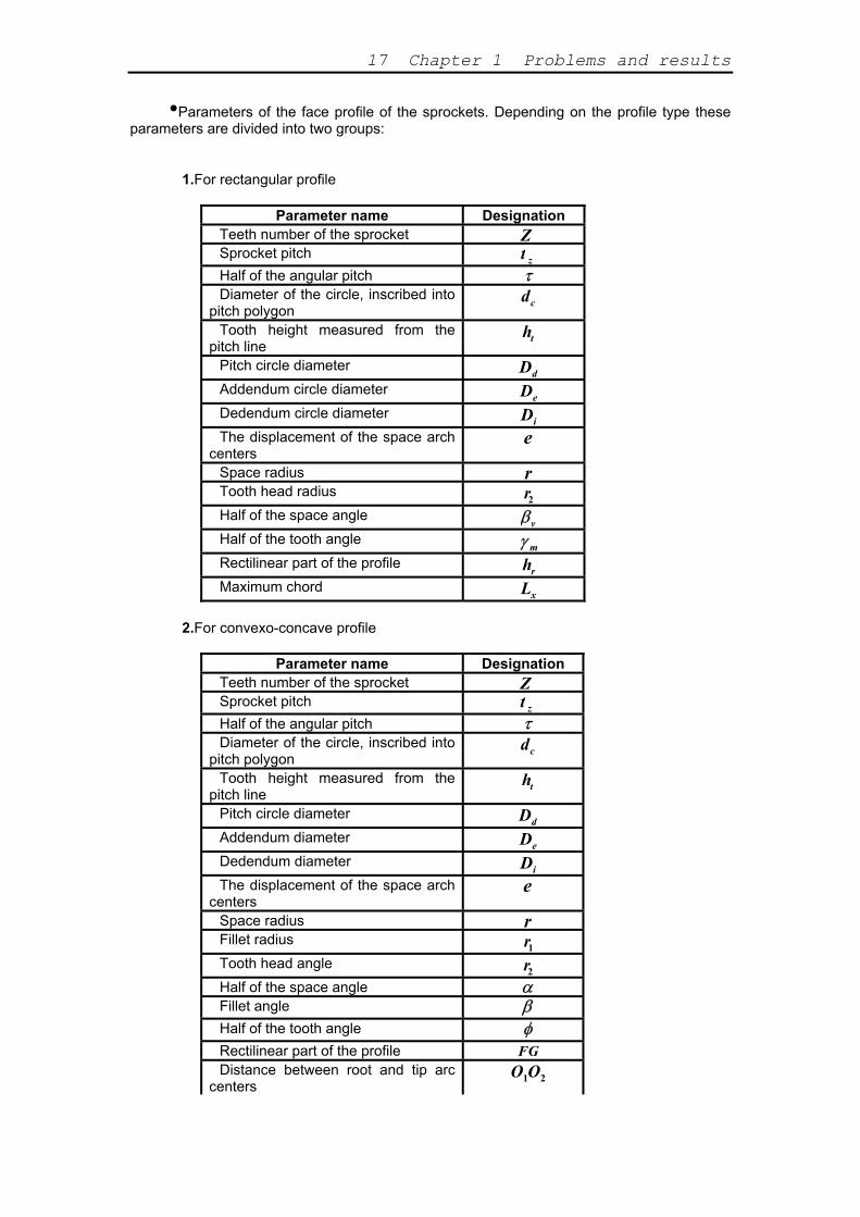
17 Chapter 1 Problems and results
•Parameters of the face profile of the sprockets. Depending on the profile type these parameters are divided into two groups:
1.For rectangular profile
Parameter name Designation Teeth number of the sprocket Z Sprocket pitch t z Half of the angular pitch τ Diameter of the circle, inscribed into
pitch polygon dc
Tooth height measured from the pitch line
ht
Pitch circle diameter Dd Addendum circle diameter De Dedendum circle diameter Di The displacement of the space arch
centers e
Space radius r Tooth head radius r2 Half of the space angle βv Half of the tooth angle γ m Rectilinear part of the profile hr Maximum chord Lx
2.For convexo-concave profile
Parameter name Designation Teeth number of the sprocket Z Sprocket pitch t z Half of the angular pitch τ Diameter of the circle, inscribed into
pitch polygon dc
Tooth height measured from the pitch line
ht
Pitch circle diameter Dd Addendum diameter De Dedendum diameter Di The displacement of the space arch
centers e
Space radius r Fillet radius r1 Tooth head angle r2 Half of the space angle α Fillet angle β Half of the tooth angle φ Rectilinear part of the profile FG Distance between root and tip arc
centers O O1 2

APM Trans User`s Guide
Coordinated of the root arch center O x1 O y1
Coordinates of the tooth addendum arch center
O x2
O y2
Maximum chord Lx •Parameters of the sprocket cross-section
Parameter name Designation Shoulder circle diameter Dc Maximum tooth width b2 Face ring diameter B Teeth's thickness at tip diameter * b3 Chamfering radius of the shoulder R Radius of chamfering of the tooth
side surface R3
* - this parameter is calculated for rectilinear profile only.
BCentre distance of the transmission elt transmissions: ••Geometry parameters
Parameter name Designation
Pulley diameter D Pulley width B Half of opening angle of the
transmission branch* ψ
* - this parameter is calculated for flat-belt transmission only. •Loading parameters
Parameter name Designation Pressure on the shaft Q Preload force F
Methods and standards
Cylindrical transmission standards •ISO CD 9085-1 (Calculation of load capacity of spur and helical gearings) ,
AGMA able for gear strength calculation. and GOST (Russian) standards are avail• Different type of basic rack can be used in calculation. Default basic rack depends on set standard.
Basic rack (Fig. 1.5) is characterized by the main profile angle α, tooth addendum coefficient h , radial clearance coefficient in the pair of initial contours c , tooth dedendum coefficient h h
a* *
cf a* *= *+ , boundary height coefficient h ha
*l* = 2 , root fillet coefficient ρf
* .
19 Chapter 1 Problems and results
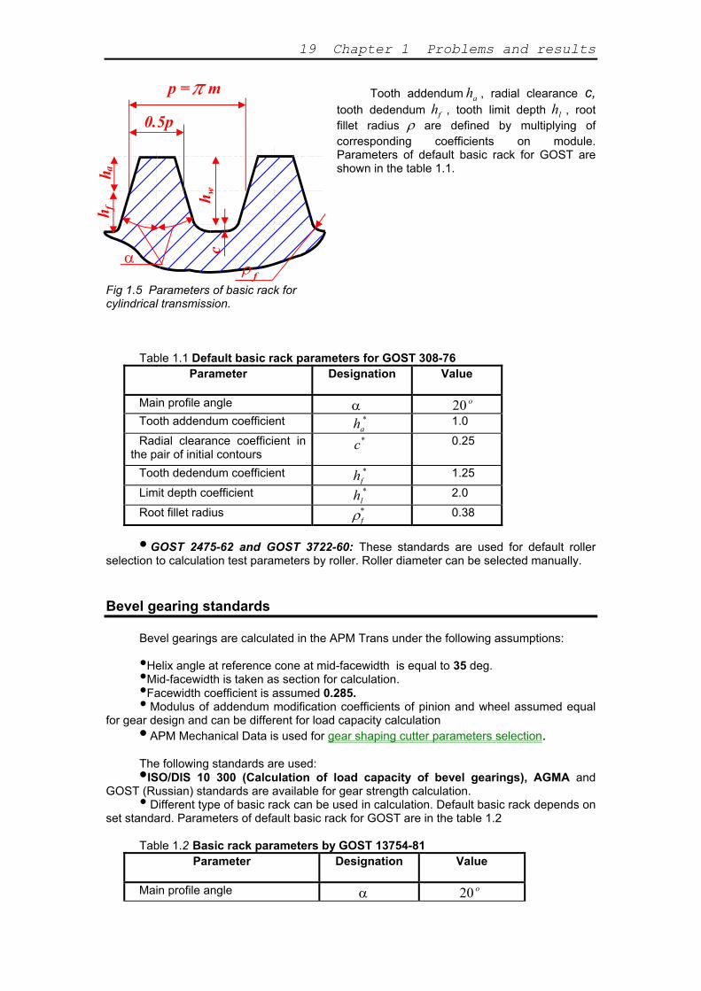
Tooth addendum , radial clearance c, tooth dedendum h
ha
f , tooth limit depth h , root fillet radius
lρ are defined by multiplying of
corresponding coefficients on module. Parameters of default basic rack for GOST are shown in the table 1.1.
Fig 1.5 Parameters of basic rack for
p = m
0.5p
α c
hh
h
f
fa
w
cylindrical transmission. Table 1.1 Default basic rack parameters for GOST 308-76
Parameter Designation Value
Main profile angle α 20 o Tooth addendum coefficient ha
* 1.0
Radial clearance coefficient in the pair of initial contours
c*
0.25
Tooth dedendum coefficient hf* 1.25
Limit depth coefficient hl* 2.0
Root fillet radius ρf* 0.38
• GOST 2475-62 and GOST 3722-60: These standards are used for default roller selection to calculation test parameters by roller. Roller diameter can be selected manually.
Bevel gearing standards
Bevel gearings are calculated in the APM Trans under the following assumptions:
Helix angle at reference cone at mid-facewidth is equal to 35 deg. •Mid-facewidth is taken as section for calculation. •Facewidth coefficient is assumed 0.285. •• Modulus of addendum modification coefficients of pinion and wheel assumed equal
for gear design and can be different for load capacity calculation • APM Mechanical Data is used for gear shaping cutter parameters selection. T•ISO/DIS 10 300 (Calculation of load capacity of bevel gearings), AGMA and
GOST (Russian) standards are available for gear strength calculation.
he following standards are used:
• Different type of basic rack can be used in calculation. Default basic rack depends on set standard. Parameters of default basic rack for GOST are in the table 1.2
Table 1.2 Basic rack parameters by GOST 13754-81
Parameter Designation Value
Main profile angle α 20 o
APM Trans User`s Guide
Teeth addendum coefficient ha* 1.0
Radial clearance coefficient in the pair of initial contours
c*
0.25
Root fillet coefficient ρf* 0.2
Worm gearing standards
• Different type of basic rack can be used in calculation. Default basic rack depends on set standard.
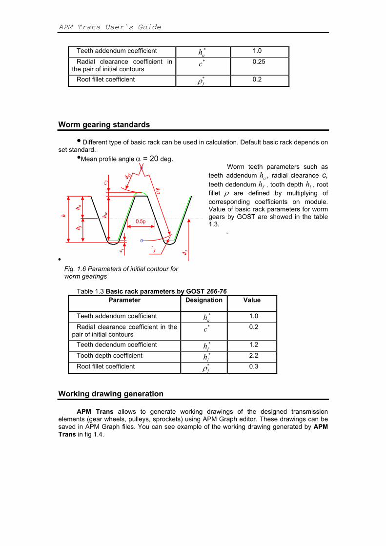
•Mean profile angle α = 20 deg. Worm teeth parameters such as
teeth addendum h , radial clearance c, teeth dedendum h
a
f , tooth depth h , root fillet
lρ are defined by multiplying of
corresponding coefficients on module. Value of basic rack parameters for worm gears by GOST are showed in the table 1.3.
•
h
hh
hc
cd
d
r
0.5p
f
f2
a
a2
w
1
2
f
d 1
.
Fig. 1.6 Parameters of initial contour for worm gearings
Table 1.3 Basic rack parameters by GOST 266-76
Parameter Designation Value
Teeth addendum coefficient ha* 1.0
Radial clearance coefficient in the pair of initial contours
c*
0.2
Teeth dedendum coefficient hf* 1.2
Tooth depth coefficient hl* 2.2
Root fillet coefficient ρf* 0.3
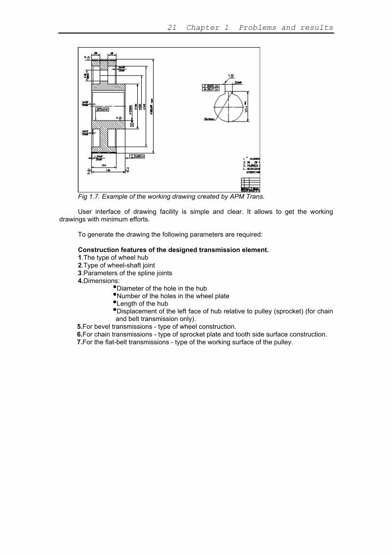
Working drawing generation
APM Trans allows to generate working drawings of the designed transmission
elements (gear wheels, pulleys, sprockets) using APM Graph editor. These drawings can be saved in APM Graph files. You can see example of the working drawing generated by APM Trans in fig 1.4.
21 Chapter 1 Problems and results
Fig 1.7. Example of the working drawing created by APM Trans. User interface of drawing facility is simple and clear. It allows to get the working
drawings with minimum efforts. To generate the drawing the following parameters are required: Construction features of the designed transmission element. 1.The type of wheel hub 2.Type of wheel-shaft joint 3.Parameters of the spline joints 4.Dimensions: •
Number of the holes in the wheel plate Diameter of the hole in the hub •Length of the hub ••Displacement of the left face of hub relative to pulley (sprocket) (for chain and belt transmission only).
5.For bevel transmissions - type of wheel construction. 6.For chain transmissions - type of sprocket plate and tooth side surface construction. 7.For the flat-belt transmissions - type of the working surface of the pulley.

APM Trans User's Guide 22
Chapter 2 How to work with APM Trans
As any other Windows application program APM Trans provides handy and intuitively clear user interface, based on the CUA (Common User Access) and GUI (Graphical User Interface) standards.
Typical sequence of actions when you work with APM Trans includes the following operations:
1. Selection of the transmission type 2. Selection of the calculation type 3. Standard selection 4. Initial data entering 5. Calculation 6. Result items selection 7. Results looking through 8. Specifying the working drawing
Type of transmission selection To select type of transmission to be calculated use Types | Transmission…
command. In the dialog box that will be displayed (see Fig. 5.9) choose type of transmission you want to design.
Type of calculation selection
Two types of calculation are implemented in the APM Trans -- transmission design and
load capacity calculation (see Chapter 1). To select type of calculation use Type | Calculation | Type of Calculation command. Type of calculation can be one of the following:
Transmission design •Calculation of maximum load for given lifetime ••Calculation of lifetime for given maximum load
Standard selection
Standard should be selected before calculation. Standard dependend data will be
selected from the database for calculation. Select Data Base | Set Standard… command to set required standard. The list of available standards is also selected from APM MechanicalDataBase.
Initial data input
To enter initial data use Data command. In response to this command dialog box for
data input will be displayed. Contents of this dialog box depend on the transmission type and type of calculation (see Fig. 5.11).
All initial data can be divided into two groups - "general", without which it is impossible to calculate the transmission and "additional", used to impose some constraints on the transmission. Usually in the dialog box that invoked in response to Data command general data are entered. This dialog box contains "More..." button, that calls dialog box for additional data input. You may not specify all additional data. The system treats any non-zero value in the edit box for additional parameter as indication that users have entered this parameter. So if you do not want specify additional parameter, you should leave zero in the respective edit
23 Chapter 2 How to work with APM Trans
box. This true for all additional parameters except for addendum modification coefficient (which can have zero value).
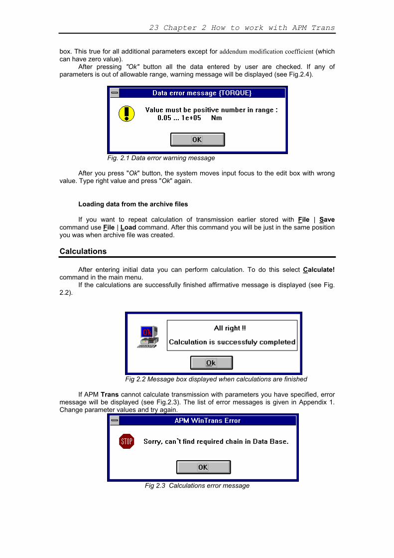
After pressing "Ok" button all the data entered by user are checked. If any of parameters is out of allowable range, warning message will be displayed (see Fig.2.4).
Fig. 2.1 Data error warning message
After you press "Ok" button, the system moves input focus to the edit box with wrong
value. Type right value and press "Ok" again. Loading data from the archive files If you want to repeat calculation of transmission earlier stored with File | Save
command use File | Load command. After this command you will be just in the same position you was when archive file was created.
Calculations
After entering initial data you can perform calculation. To do this select Calculate!
command in the main menu. If the calculations are successfully finished affirmative message is displayed (see Fig.
2.2).
Fig 2.2 Message box displayed when calculations are finished
If APM Trans cannot calculate transmission with parameters you have specified, error message will be displayed (see Fig.2.3). The list of error messages is given in Appendix 1. Change parameter values and try again.
Fig 2.3 Calculations error message
APM Trans User's Guide 24
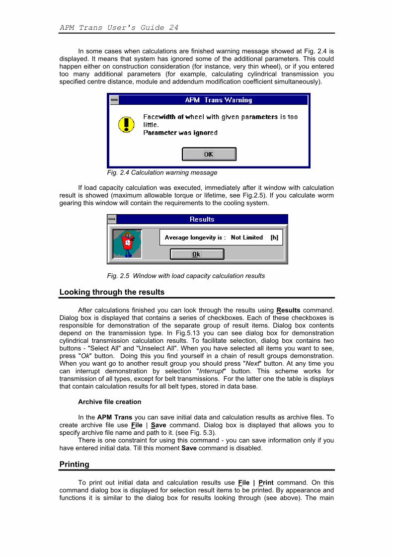
In some cases when calculations are finished warning message showed at Fig. 2.4 is displayed. It means that system has ignored some of the additional parameters. This could happen either on construction consideration (for instance, very thin wheel), or if you entered too many additional parameters (for example, calculating cylindrical transmission you specified centre distance, module and addendum modification coefficient simultaneously).
Fig. 2.4 Calculation warning message
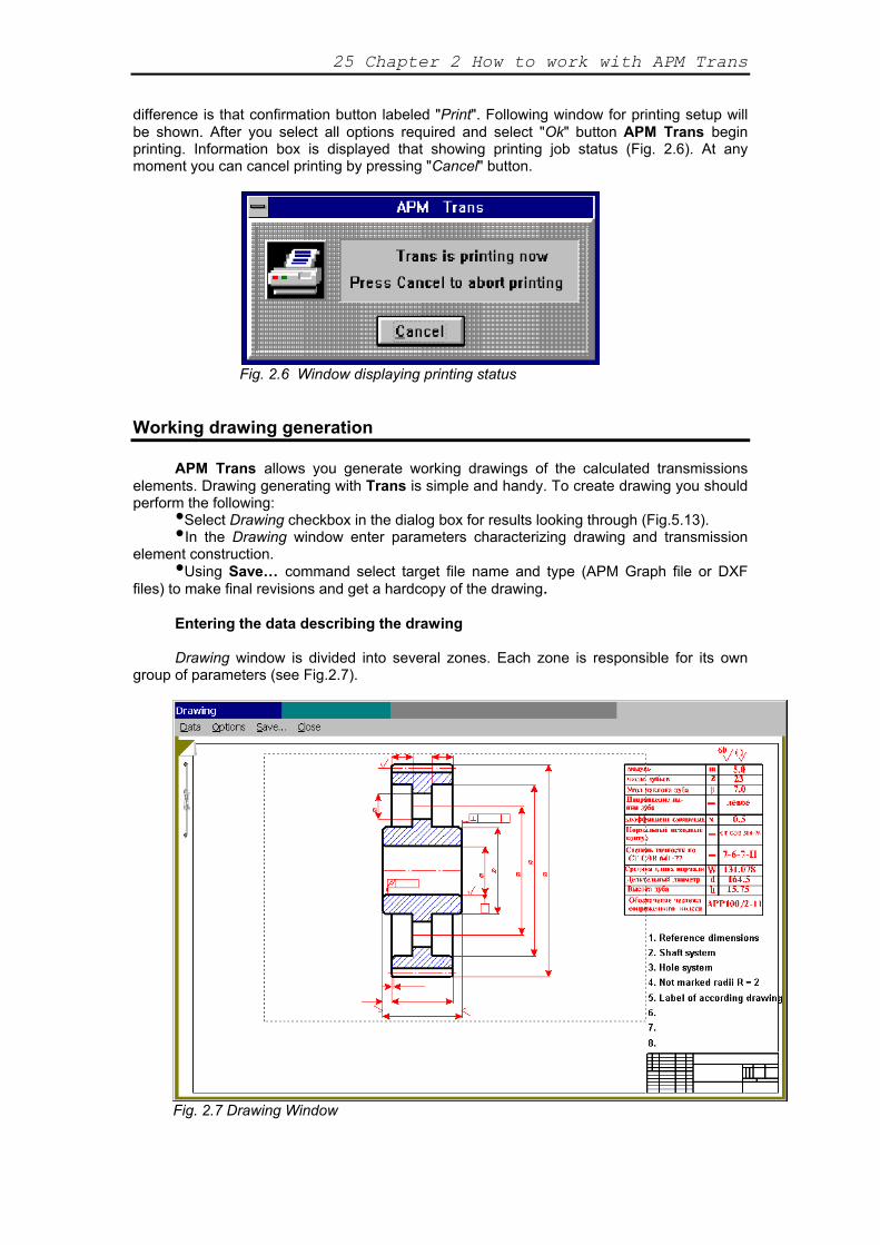
If load capacity calculation was executed, immediately after it window with calculation result is showed (maximum allowable torque or lifetime, see Fig.2.5). If you calculate worm gearing this window will contain the requirements to the cooling system.
Fig. 2.5 Window with load capacity calculation results Looking through the results
After calculations finished you can look through the results using Results command.
Dialog box is displayed that contains a series of checkboxes. Each of these checkboxes is responsible for demonstration of the separate group of result items. Dialog box contents depend on the transmission type. In Fig.5.13 you can see dialog box for demonstration cylindrical transmission calculation results. To facilitate selection, dialog box contains two buttons - "Select All" and "Unselect All". When you have selected all items you want to see, press "Ok" button. Doing this you find yourself in a chain of result groups demonstration. When you want go to another result group you should press "Next" button. At any time you can interrupt demonstration by selection "Interrupt" button. This scheme works for transmission of all types, except for belt transmissions. For the latter one the table is displays that contain calculation results for all belt types, stored in data base.
Archive file creation In the APM Trans you can save initial data and calculation results as archive files. To
create archive file use File | Save command. Dialog box is displayed that allows you to specify archive file name and path to it. (see Fig. 5.3).
There is one constraint for using this command - you can save information only if you have entered initial data. Till this moment Save command is disabled.
Printing
To print out initial data and calculation results use File | Print command. On this
command dialog box is displayed for selection result items to be printed. By appearance and functions it is similar to the dialog box for results looking through (see above). The main
25 Chapter 2 How to work with APM Trans
difference is that confirmation button labeled "Print". Following window for printing setup will be shown. After you select all options required and select "Ok" button APM Trans begin printing. Information box is displayed that showing printing job status (Fig. 2.6). At any moment you can cancel printing by pressing "Cancel" button.
Fig. 2.6 Window displaying printing status
Working drawing generation APM Trans allows you generate working drawings of the calculated transmissions
elements. Drawing generating with Trans is simple and handy. To create drawing you should perform the following: ••In the Drawing window enter parameters characterizing drawing and transmission element construction.
Select Drawing checkbox in the dialog box for results looking through (Fig.5.13).
•Using Save… command select target file name and type (APM Graph file or DXF files) to make final revisions and get a hardcopy of the drawing.
Entering the data describing the drawing Drawing window is divided into several zones. Each zone is responsible for its own
group of parameters (see Fig.2.7).
Fig. 2.7 Drawing Window
APM Trans User's Guide 26
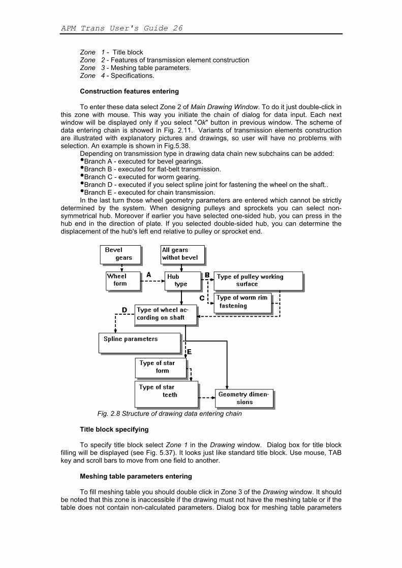
Zone 1 - Title block Zone 2 - Features of transmission element construction Zone 3 - Meshing table parameters. Zone 4 - Specifications. Construction features entering To enter these data select Zone 2 of Main Drawing Window. To do it just double-click in
this zone with mouse. This way you initiate the chain of dialog for data input. Each next window will be displayed only if you select "Ok" button in previous window. The scheme of data entering chain is showed in Fig. 2.11. Variants of transmission elements construction are illustrated with explanatory pictures and drawings, so user will have no problems with selection. An example is shown in Fig.5.38.
DBranch А - executed for bevel gearings. epending on transmission type in drawing data chain new subchains can be added: •Branch B - executed for flat-belt transmission. •Branch C - executed for worm gearing. •Branch D - executed if you select spline joint for fastening the wheel on the shaft.. ••Branch E - executed for chain transmission.
In the last turn those wheel geometry parameters are entered which cannot be strictly determined by the system. When designing pulleys and sprockets you can select non-symmetrical hub. Moreover if earlier you have selected one-sided hub, you can press in the hub end in the direction of plate. If you selected double-sided hub, you can determine the displacement of the hub's left end relative to pulley or sprocket end.
Fig. 2.8 Structure of drawing data entering chain
Title block specifying To specify title block select Zone 1 in the Drawing window. Dialog box for title block
filling will be displayed (see Fig. 5.37). It looks just like standard title block. Use mouse, TAB key and scroll bars to move from one field to another.
Meshing table parameters entering To fill meshing table you should double click in Zone 3 of the Drawing window. It should
be noted that this zone is inaccessible if the drawing must not have the meshing table or if the table does not contain non-calculated parameters. Dialog box for meshing table parameters

27 Chapter 2 How to work with APM Trans
input is displayed (see Fig. 5.39). In this dialog box you should enter parameters that could not be calculated - tooth line direction, designation of conjugate element drawing, etc.
Specifications entering If you want to set up specifications, choose Zone 4 of the Drawing window. The dialog
box for specifications input will be displayed (see Fig.5.40). Parameters that you should enter in this window are described in chapter 1.
Grawing generation To generate drawing use Save… command of the Drawing window. When you select
this command, standard Save file dialog box is displayed. Quitting APM Trans To quit APM Trans use File | Exit command.
APM Trans User's Guide 28
Chapter 3 APM Trans—answers & questions
Question: APM Trans—what is it? Answer: APM Trans is the program for mechanical transmission calculation and
design developed in the Research and Software Development Center APM Ltd., Moscow, Russia.
Q: What types of transmission could be calculated with APM Trans? A
external and internal spur gearing with involute teeth : APM Trans allows to calculate the following types of transmission: •helical gearings •herring bone gearings ••bevel gearing with standard involute
tworm gearings eeth and circular teeth •flat belt transmissions •V-belt transmission ••chain transmission
See section Types of transmission in Chapter 1. A: What parameters could be calculated Trans? Q: Using APM Trans you can calculate the following parameters:
Geometry parameters •Forces, acting in the transmission •Longevity •Maximum allowable load ••Checking parameters
For detail see section Results in Chapter 1. A: How to contact APM? Q: : Phone : +7(495) 585-06-11(fax), 514-84-19.
Send the letter to : Research and Software Development Center APM Ltd., Korolev-Center, box 58, Moscow Region,
Russia, 141070 e-mail: [email protected]

35 Chapter 4 APM Trans environment
CHAPTER 4 The APM Trans environment
In this chapter we give you a brief description of the most frequently used APM Trans
environment components. Systematic description of all menu commands and dialog box options is given in Chapter 5.
The environment components Menus
Menu is a displayed list of commands (actions) available when you are working with a program. We shall speak about four kinds of menu—system, program, main and popup.
System menu (see Fig. 5.42, Chapter 5) is your "window to Windows." It allows you to interact with Windows. Using the system menu you can exit the program, interrupt the program execution for a some time and switch to another program, resize and move your program window and so on. For the list of System menu commands see section System Menu in Chapter 5.
The program menu contains commands of the application program. The program menu usually has hierarchical structure with the main menu at the top. The main menu is always on the screen. Each item of the main menu is either a command (which performs an immediate action), or a name of the next level menu—so called popup menu. (The word "popup" reflects a style of menu—it is used for menus, primarily invisible and called to screen ("popup") only when necessary.) Items of popup menu are, in their turn, either commands, or popup menus of the next level in menu hierarchy. Fig. 5.1 (Chapter 5) demonstrates the main menu of the APM Trans together with all its popup menus.
Dialog boxes
Dialog boxes are windows that are used for data input, options selection, for displaying
additional and explanatory information, warning messages—in other words, these are windows used to keep up the dialog with a user. You can easily see where you will meet a dialog box—command (in the menu and on the buttons) invoking a dialog box is followed by ellipsis.
Information windows
Information windows are used to display the state of the currently solving problem. Transmission Type window
Transmission Type window is located in the left hand upper part of the screen (see Fig. 4.1). In this window picture of current transmission and its name are present.
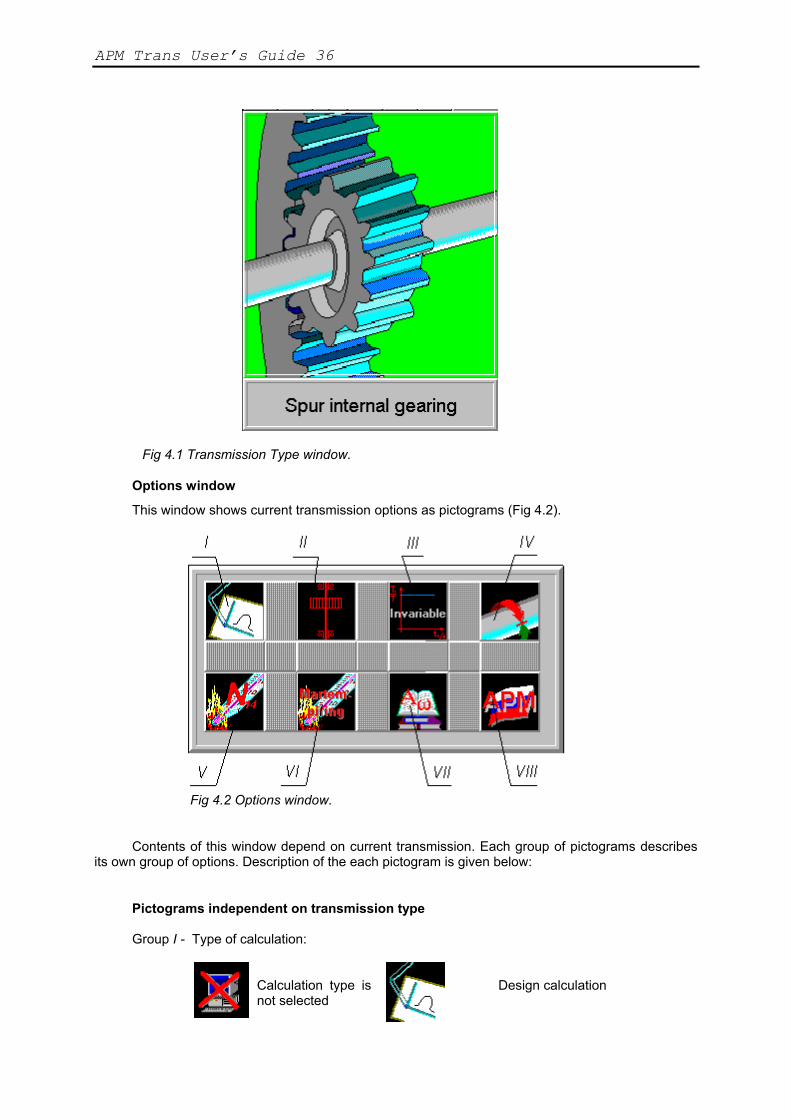
APM Trans User’s Guide 36
Fig 4.1 Transmission Type window.
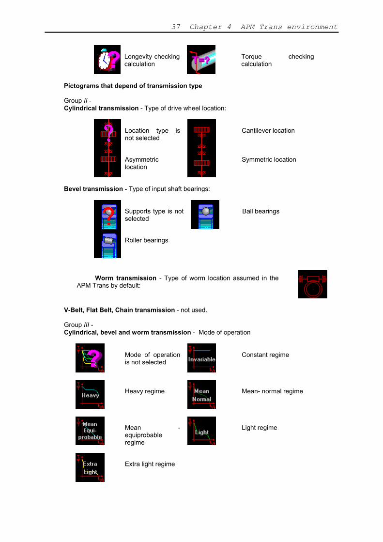
Options window
This window shows current transmission options as pictograms (Fig 4.2).
Fig 4.2 Options window.
Contents of this window depend on current transmission. Each group of pictograms describes its own group of options. Description of the each pictogram is given below:
Pictograms independent on transmission type Group I - Type of calculation:
Calculation type is not selected
Design calculation
37 Chapter 4 APM Trans environment
Longevity checking calculation
Torque checking calculation
Pictograms that depend of transmission type Group II - Cylindrical transmission - Type of drive wheel location:
Location type is not selected
Cantilever location
Asymmetric location
Symmetric location
Bevel transmission - Type of input shaft bearings:
Supports type is not selected
Ball bearings
Roller bearings
Worm transmission - Type of worm location assumed in the
APM Trans by default:
V-Belt, Flat Belt, Chain transmission - not used. Group III - Cylindrical, bevel and worm transmission - Mode of operation
Mode of operation is not selected
Constant regime
Heavy regime
Mean- normal regime
Mean - equiprobable regime
Light regime
Extra light regime
APM Trans User’s Guide 38
V-Belt, Flat Belt, Chain transmission - not used.
Group IV - Cylindrical and bevel transmission - Reversibility of transmission
Reversible transmission
Non-reversible transmission
Worm, V-Belt, Flat Belt, Chain transmission - not used.
Group V- Cylindrical and bevel transmission - Thermal treatment of drive wheel
Thermal treatment is not selected
Martempering
Hardening
Carburazing and Nitrocarburazing
Nitriding
Worm transmission - materials of wheel rim.
Material is not selected
Tin bronze
Tinless bronze
Cast iron
Belt transmission - type of belt adjustment mechanism.
Type is not selected
Adjustment by shaft displacement
Adjustment by roller
Chain transmission - type of chain lubrication.

39 Chapter 4 APM Trans environment
Lubrication type is not selected
Transmission is not lubricated
Periodical lubrication
Aperodical lubrication
Oil bath lubrication
Drop feed lubrication
Intra-hinge lubrication
Lubrication by spraying
Circular lubrication
Group VI-
Cylindrical and bevel transmission - type of thermal treatment of driven wheel (see group VI above)
Worm transmission - material of worm assumed in the APM Trans by default (Steel).
Belt transmission - not used. Chain transmission - type of sprocket profile.
Profile not selected
Rectilinear profile
Convexo-concave profile
Group VII -
Cylindrical transmission - show numerical set to which center distance will be rounded to.
Non-standard distance (Ra40 set)
Standard interaxis distance
Bevel transmission - Show interaxis angle assumed in the APM Trans by default (90 deg).
APM Trans User’s Guide 40
Worm, belt and chain transmission - not used..
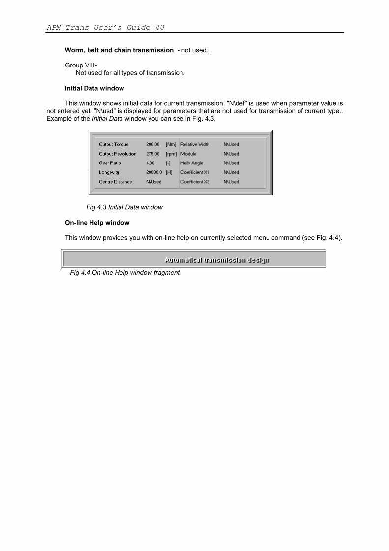
Group VIII- Not used for all types of transmission. Initial Data window This window shows initial data for current transmission. "N\def" is used when parameter value is
not entered yet. "N\usd" is displayed for parameters that are not used for transmission of current type.. Example of the Initial Data window you can see in Fig. 4.3.
Fig 4.3 Initial Data window
On-line Help window This window provides you with on-line help on currently selected menu command (see Fig. 4.4).
Fig 4.4 On-line Help window fragment
41 Chapter 5 Command reference
Chapter 5 Command reference
In this section we give you a complete description of each menu command and dialog
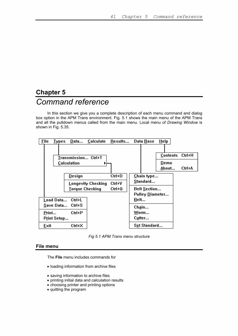
box option in the APM Trans environment. Fig. 5.1 shows the main menu of the APM Trans and all the pulldown menus called from the main menu. Local menu of Drawing Window is shown in Fig. 5.35.
Fig 5.1 APM Trans menu structure
File menu
The File menu includes commands for
• loading information from archive files • saving information to archive files • printing initial data and calculation results • choosing printer and printing options • quitting the program
APM Trans Users Guide 42
Fig 5.2 The File menu Load command
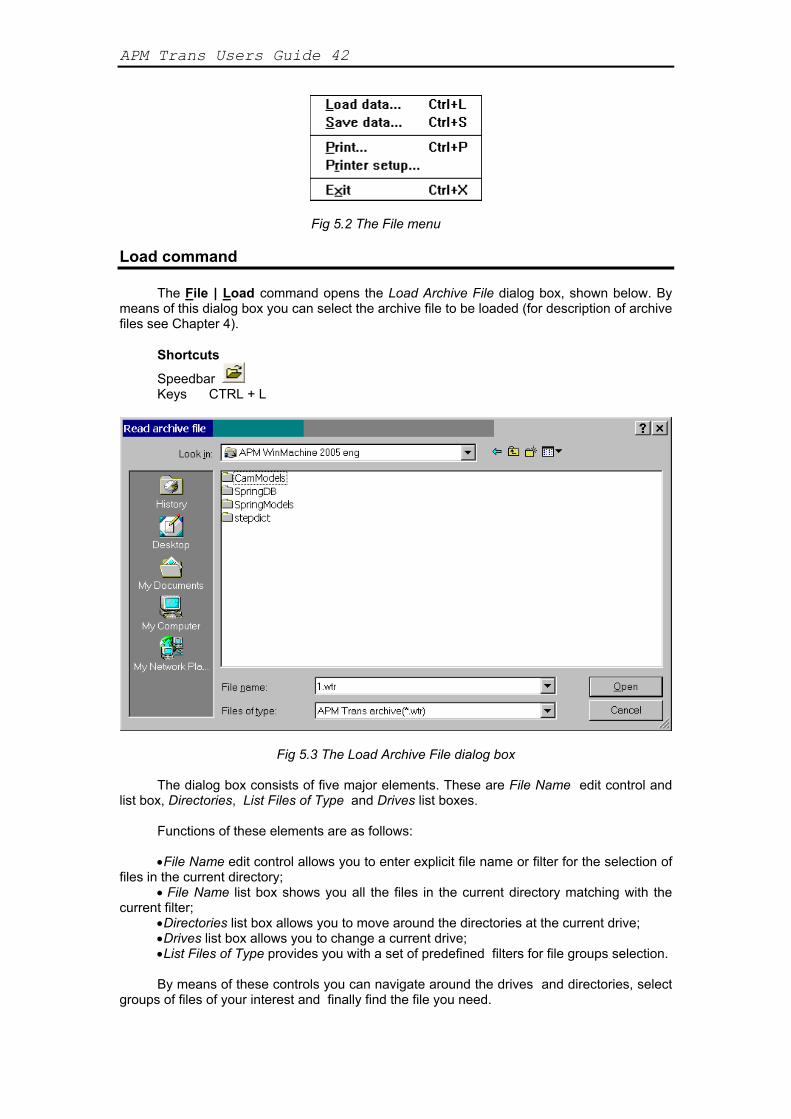
The File | Load command opens the Load Archive File dialog box, shown below. By means of this dialog box you can select the archive file to be loaded (for description of archive files see Chapter 4).
Shortcuts
Speedbar Keys CTRL + L
Fig 5.3 The Load Archive File dialog box
The dialog box consists of five major elements. These are File Name edit control and list box, Directories, List Files of Type and Drives list boxes.
Functions of these elements are as follows:
•File Name edit control allows you to enter explicit file name or filter for the selection of files in the current directory;
• File Name list box shows you all the files in the current directory matching with the current filter;
•Directories list box allows you to move around the directories at the current drive; •Drives list box allows you to change a current drive; •List Files of Type provides you with a set of predefined filters for file groups selection.
By means of these controls you can navigate around the drives and directories, select
groups of files of your interest and finally find the file you need.
43 Chapter 5 Command reference
Save command
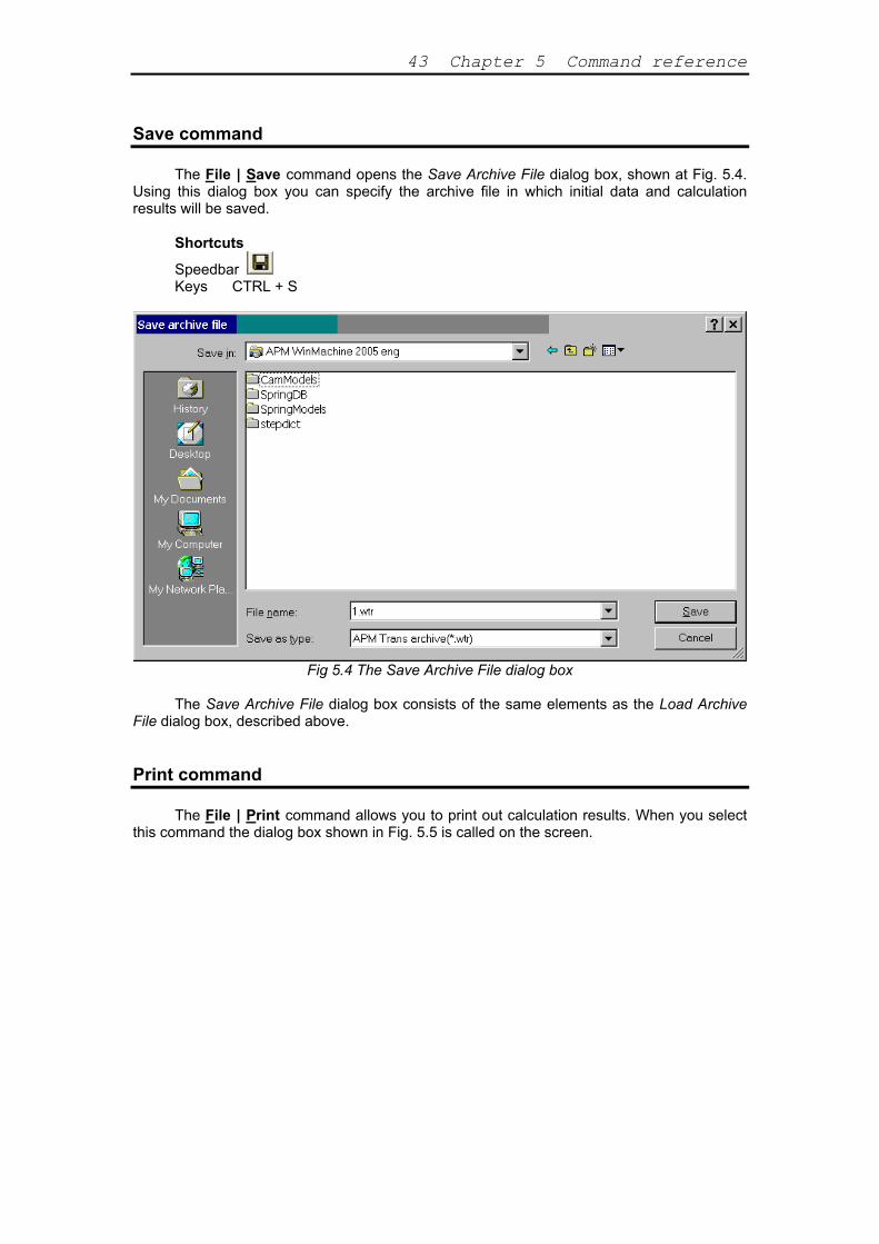
The File | Save command opens the Save Archive File dialog box, shown at Fig. 5.4. Using this dialog box you can specify the archive file in which initial data and calculation results will be saved.
Shortcuts
Speedbar Keys CTRL + S
Fig 5.4 The Save Archive File dialog box
The Save Archive File dialog box consists of the same elements as the Load Archive
File dialog box, described above. Print command
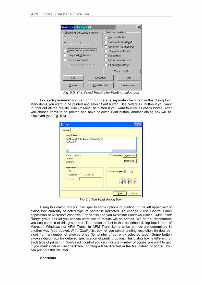
The File | Print command allows you to print out calculation results. When you select this command the dialog box shown in Fig. 5.5 is called on the screen.
APM Trans Users Guide 44
Fig 5.5 The Select Results for Printing dialog box
For each parameter you can print out there is separate check box in this dialog box.
Mark items you want to be printed and select Print button. Use Select All button if you want to print out all the results. Use Unselect All button if you want to clear all check boxes. After you choose items to be printed and have selected Print button, another dialog box will be displayed (see Fig. 5.6).
Fig 5.6 The Print dialog box.
Using this dialog box you can specify some options of printing. In the left upper part of
dialog box currently selected type of printer is indicated. To change it use Control Panel application of Microsoft Windows. For details see you Microsoft Windows User's Guide. Print Range group box let you choose what part of results will be printed. We do not recommend you use controls of this group box. The matter of fact is that described dialog box is part of Microsoft Windows not APM Trans. In APM Trans items to be printed are determined in another way (see above). Print Quality list box let you select printing resolution (in dots per inch) from a number of allowed ones (for printer of currently selected type). Setup button invokes dialog box for detailed specification of printing option. This dialog box is different for each type of printer. In Copies edit control you can indicate number of copies you want to get. If you mark Print to File check box, printing will be directed in the file instead of printer. You can print out this file later.
Shortcuts

45 Chapter 5 Command reference
Speedbar Keys CTRL + P
Printer setup command
The File | Printer setup command invokes the Print Setup dialog box shown at Fig. 5.7.
With this dialog box you can specify printer settings. Using controls of Printer group box you can select type of printer (from a number of already installed in Microsoft Windows. To install new printer use Printers utility of Control Panel application, described in your Microsoft Windows User's Guide). With Orientation group box controls you can select how the printing will be oriented relatively to paper sheetparallel to short side (Portrait) or to long side (Landscape). Controls of Paper group box let you choose paper sheet size (Size list box) and the type of paper advance (Source group box). And finally, Options button invokes printer-specific dialog box for more detailed tuning of printing.
Exit command
Use File | Exit command to exit APM Trans. Shortcuts Keys CTRL + X
Fig 5.7 The Print Setup dialog box
Types menu
The Types command of the main menu invokes Types popup menu shown at Fig. 5.8.
Fig 5.8 Types popup menu
Here we give the description of the Types menu commands. Transmission command
APM Trans Users Guide 46
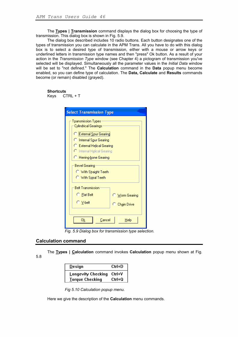
The Types | Transmission command displays the dialog box for choosing the type of transmission. This dialog box is shown in Fig. 5.9.
The dialog box described includes 10 radio buttons. Each button designates one of the types of transmission you can calculate in the APM Trans. All you have to do with this dialog box is to select a desired type of transmission, either with a mouse or arrow keys or underlined letters in transmission type names and then "press" Ok button. As a result of your action in the Transmission Type window (see Chapter 4) a pictogram of transmission you've selected will be displayed. Simultaneously all the parameter values in the Initial Data window will be set to "not defined." The Calculation command in the Data popup menu become enabled, so you can define type of calculation. The Data, Calculate and Results commands become (or remain) disabled (grayed).
Shortcuts Keys CTRL + T
Fig. 5.9 Dialog box for transmission type selection. Calculation command
The Types | Calculation command invokes Calculation popup menu shown at Fig. 5.8
Fig 5.10 Calculation popup menu.
Here we give the description of the Calculation menu commands.
47 Chapter 5 Command reference
Design command
Design command select transmission design as current type of calculation (see Chapter 1).
Shortcuts Keys CTRL + D
Longevity Checking command
This command selects longevity checking as current type of calculation (see Chapter 1).
Shortcuts Keys CTRL + V
Torque Checking command
This command selects maximum torque checking as current type of calculation (see Chapter 1).
Shortcuts Keys CTRL + Q
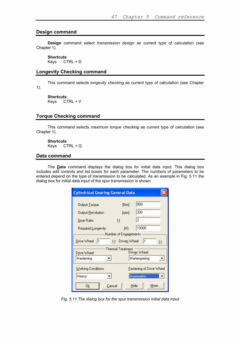
Data command
The Data command displays the dialog box for initial data input. This dialog box includes edit controls and list boxes for each parameter. The numbers of parameters to be entered depend on the type of transmission to be calculated. As an example in Fig. 5.11 the dialog box for initial data input of the spur transmission is shown.
Fig. 5.11 The dialog box for the spur transmission initial data input

APM Trans Users Guide 48
When you finish input of all the parameters, presented in the dialog box, select Ok button to inform a program that you confirm values you have entered. Immediately after this, the values you have entered will be displayed in the Initial Data window. Simultaneously in the Options window will be displayed all the options selected. Of course, at any moment you can select a Cancel button to cancel a dialog box. You must remember, however, that you cannot perform calculation until you define all the parameters.
To avoid errors during the data input, checking for allowable values is implemented. The width of allowable intervals is sufficiently big to include all cases of practical interest. These intervals for initial data are depend to current transmission type.
If you have entered the value that is out of allowable interval for respective parameter, the warning message will be displayed after you select Ok button.
Fig. 5.12 An example of warning message displayed when data are out of allowable limits.
After you select Ok button you will be brought back just to that item of Initial Data dialog
where you entered erroneous value. Besides checking for allowable values there are some other kinds of initial data control.
Description of the initial data is given in the Chapter 1. Calculate command
The Calculate command of the main menu starts calculation. Shortcuts
Speedbar
Results command
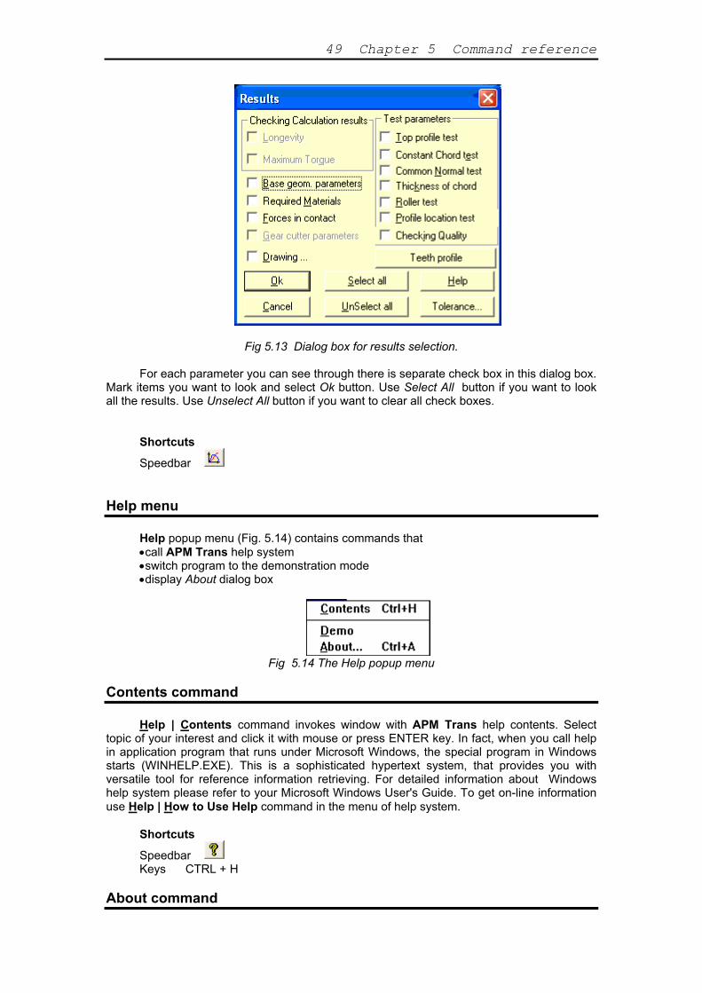
The Results command of the main menu invokes the Results dialog box. Using this dialog box user can select and look through any of the calculation results. Contents of this dialog box depend on transmission type. In Fig.5.13 you can see an example of the Results dialog box for cylindrical transmission.
49 Chapter 5 Command reference
Fig 5.13 Dialog box for results selection. For each parameter you can see through there is separate check box in this dialog box.
Mark items you want to look and select Ok button. Use Select All button if you want to look all the results. Use Unselect All button if you want to clear all check boxes.
Shortcuts
Speedbar
Help menu Help popup menu (Fig. 5.14) contains commands that •call APM Trans help system •switch program to the demonstration mode •display About dialog box
Fig 5.14 The Help popup menu
Contents command
Help | Contents command invokes window with APM Trans help contents. Select topic of your interest and click it with mouse or press ENTER key. In fact, when you call help in application program that runs under Microsoft Windows, the special program in Windows starts (WINHELP.EXE). This is a sophisticated hypertext system, that provides you with versatile tool for reference information retrieving. For detailed information about Windows help system please refer to your Microsoft Windows User's Guide. To get on-line information use Help | How to Use Help command in the menu of help system.
Shortcuts
Speedbar Keys CTRL + H
About command
APM Trans Users Guide 50
Help | About command calls About dialog box on the screen. It displays the program
name and the version together with the license information.
Shortcuts Keys CTRL + A
Drawing subsystem commands
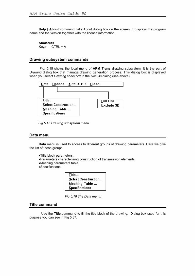
Fig. 5.15 shows the local menu of APM Trans drawing subsystem. It is the part of
Drawing dialog box that manage drawing generation process. This dialog box is displayed when you select Drawing checkbox in the Results dialog (see above).
Fig 5.15 Drawing subsystem menu.
Data menu Data menu is used to access to different groups of drawing parameters. Here we give
the list of these groups: •Title block parameters. •Parameters characterizing construction of transmission elements. •Meshing parameters table. •Specifications.
Fig 5.16 The Data menu.
Title command
Use the Title command to fill the title block of the drawing. Dialog box used for this purpose you can see in Fig 5.37.

51 Chapter 5 Command reference
Fig 5.17 Dialog box for title block filling Use TAB and SHIFT+TAB keys to move around the edit controls. To access invisible
controls use scroll bar at the bottom of the window. Ok button is used to close dialog box and confirm entered data.
Select construction command
Select construction command is used to specify features of transmission
construction. By this command you start the chain of data input steps. Each member of this chain is the dialog box with pictographic radio-buttons. These buttons represent the possible variants of transmission construction. Select appropriate buttons to specify desired transmission construction. As an example in Fig.5.18 you can see the dialog box used to select the type of wheel-shaft joint. The second pictographic button is selected ("pressed in"), indicating that user have choose the keyed type of wheel-shaft joint.
Length of data input chain and its contents depend on transmission type (see Chapter 2).
Fig 5.18 Dialog box used to select the type of wheel - shaft joint.
APM Trans Users Guide 52
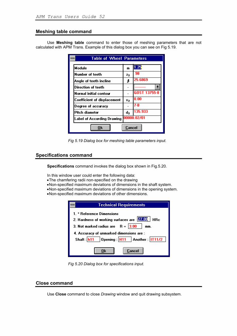
Meshing table command Use Meshing table command to enter those of meshing parameters that are not
calculated with APM Trans. Example of this dialog box you can see on Fig 5.19.
Fig 5.19 Dialog box for meshing table parameters input.
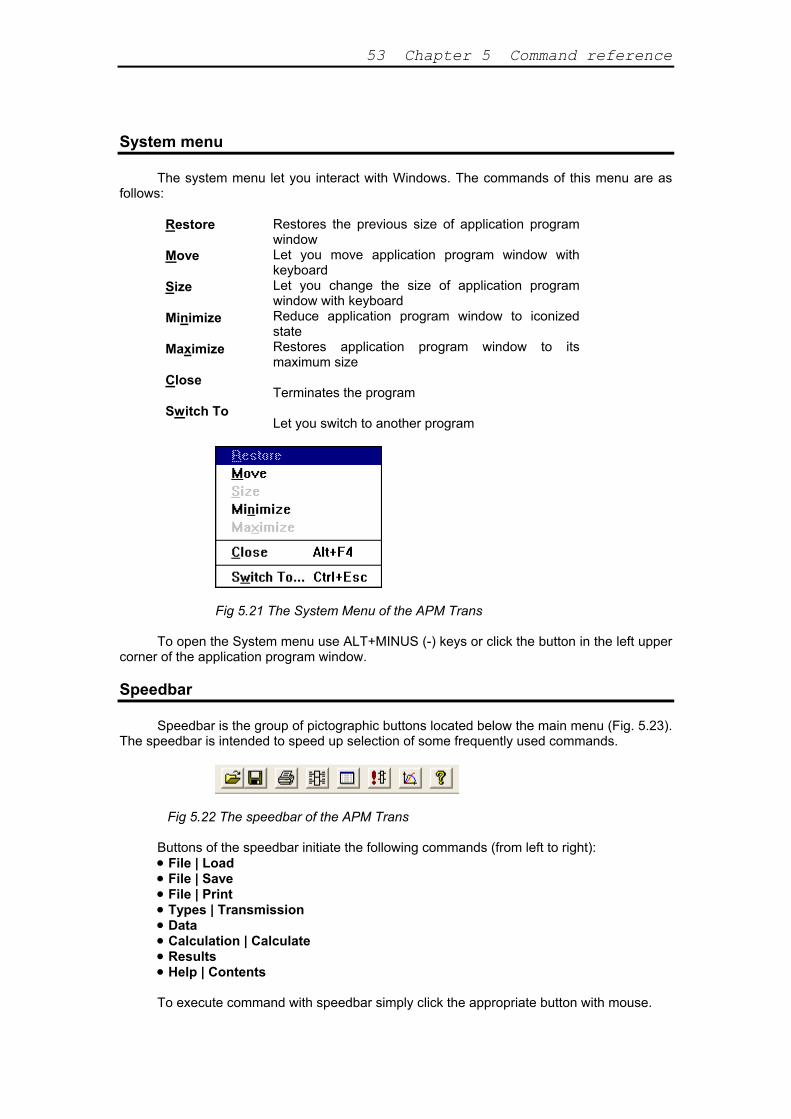
Specifications command
Specifications command invokes the dialog box shown in Fig.5.20. In this window user could enter the following data: •The chamfering radii non-specified on the drawing •Non-specified maximum deviations of dimensions in the shaft system. •Non-specified maximum deviations of dimensions in the opening system. •Non-specified maximum deviations of other dimensions.
Fig 5.20 Dialog box for specifications input.
Close command Use Close command to close Drawing window and quit drawing subsystem.
53 Chapter 5 Command reference
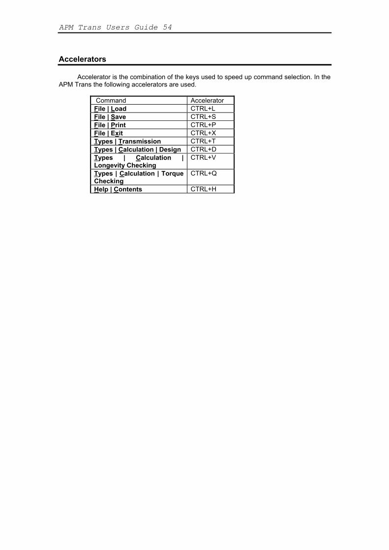
System menu The system menu let you interact with Windows. The commands of this menu are as
follows:
Restore Move Size Minimize Maximize Close Switch To
Restores the previous size of application program window Let you move application program window with keyboard Let you change the size of application program window with keyboard Reduce application program window to iconized state Restores application program window to its maximum size Terminates the program Let you switch to another program
Fig 5.21 The System Menu of the APM Trans
To open the System menu use ALT+MINUS (-) keys or click the button in the left upper
corner of the application program window.
Speedbar Speedbar is the group of pictographic buttons located below the main menu (Fig. 5.23).
The speedbar is intended to speed up selection of some frequently used commands.
Fig 5.22 The speedbar of the APM Trans Buttons of the speedbar initiate the following commands (from left to right): • File | Load • File | Save • File | Print • Types | Transmission • Data • Calculation | Calculate • Results • Help | Contents To execute command with speedbar simply click the appropriate button with mouse.
APM Trans Users Guide 54
Accelerators
Accelerator is the combination of the keys used to speed up command selection. In the
APM Trans the following accelerators are used.
Command Accelerator File | Load CTRL+L File | Save CTRL+S File | Print CTRL+P File | Exit CTRL+X Types | Transmission CTRL+T Types | Calculation | Design CTRL+D Types | Calculation | Longevity Checking
CTRL+V
Types | Calculation | Torque Checking
CTRL+Q
Help | Contents CTRL+H
55
Contents Introduction .............................................................................................................................................. 1 APM Trans-what is it ? ............................................................................................................................ 1 Hardware and software requirements....................................................................................................... 1 What's in this manual ............................................................................................................................... 1 Typefaces used in this book ..................................................................................................................... 2 How to contact APM................................................................................................................................ 2 Chapter 1 Problems and results .......................................................................................................... 3 Transmission types ................................................................................................................................... 3 Calculation types ...................................................................................................................................... 3 Initial data................................................................................................................................................. 4 Results ...................................................................................................................................................... 11 Results: Cylindrical gearings.................................................................................................................... 11 Results: Bevel gearings ............................................................................................................................ 14 Results: Worm gearings ........................................................................................................................... 16 Results: Chain transmissions.................................................................................................................... 16 Results: Belt transmissions....................................................................................................................... 18 Methods and standards ............................................................................................................................. 18 Working drawing generation.................................................................................................................... 20 Construction features of the designed transmission element.................................................................... 21 Chapter 2 How to work with APM Trans ................................................................................................ 22 Type of transmission selection ................................................................................................................. 22 Type of calculation selection.................................................................................................................... 22 Type of calculation selection.................................................................................................................... 22 Initial data input........................................................................................................................................ 22 Calculations .............................................................................................................................................. 23 Looking through the results...................................................................................................................... 24 Printing ..................................................................................................................................................... 24 Working drawing generation.................................................................................................................... 25 Chapter 3 APM Trans--answers & questions .................................................................................... 28 APM Trans—what is it?........................................................................................................................... 28 What types of transmission could be calculated with APM Trans? ......................................................... 28 What parameters could be calculated Trans? ........................................................................................... 28 How to contact APM? .............................................................................................................................. 28 CHAPTER 5 The APM Trans environment ......................................................................................... 35 The environment components .................................................................................................................. 35 Menus ....................................................................................................................................................... 35 Dialog boxes............................................................................................................................................. 35 Information windows ............................................................................................................................... 35 Chapter 6 Command reference................................................................................................................. 41 File menu.................................................................................................................................................. 41 Load command ......................................................................................................................................... 42 Save command ......................................................................................................................................... 43 Print command ......................................................................................................................................... 43 Printer setup command............................................................................................................................. 45 Exit command........................................................................................................................................... 45 Types menu .............................................................................................................................................. 45 Transmission command............................................................................................................................ 45 Calculation command............................................................................................................................... 46 Design command...................................................................................................................................... 47 Longevity Checking command................................................................................................................. 47 Torque Checking command ..................................................................................................................... 47
APM Trans Users Guide 56
Data command.......................................................................................................................................... 47 Calculate command .................................................................................................................................. 48 Results command ..................................................................................................................................... 48 Help menu ................................................................................................................................................ 49 Contents command ................................................................................................................................... 49 About command ....................................................................................................................................... 49 Drawing subsystem commands ................................................................................................................ 50 Data menu ................................................................................................................................................ 50 Title command.......................................................................................................................................... 50 Select construction command................................................................................................................... 51 Meshing table command........................................................................................................................... 52 Specifications command........................................................................................................................... 52 Close command ........................................................................................................................................ 52 System menu ............................................................................................................................................ 53 Speedbar ................................................................................................................................................... 53 Accelerators.............................................................................................................................................. 54

57
Index About command, 49 Accelerators, 54 AutoCAD, 27 Bevel gearing standards, 19 Calculate command, 48 Calculation command, 46 Calculation types, 3 Close command, 52 Construction features entering, 26 Contents command, 49 Cylindrical transmission standards, 18 Data command, 47 Data menu, 50 Design command, 47 Design under constraints, 4 Dialog boxes, 35 Drawing
Construction features of the designed transmission element, 21
Drawing generation, 25 Drawing subsystem commands, 50 Exit command, 45 File menu, 41 Help menu, 49 Information windows, 35 Initial data (additional)
Belt transmissions, 8 Bevel gearings, 6 Chain transmissions, 8 Cylindrical transmissions, 4, 5 Worm gearings, 7
Initial data (general) Belt transmissions, 8 Bevel gearings, 5 Chain transmissions, 8 Cylindrical gearings, 4, 5 Worm gearings, 7
Initial data window, 40 Load archive file dialog box, 42 Load Archive File dialog box, 42 Load capacity calculation, 4 Load command, 42
Longevity Checking command, 47 Menu, 35 Menu stucture, 41 Meshing table, 26 Meshing table command, 52 On-line help window, 40 Options window, 36 Print command, 43 Print dialog box, 44 Print Selection dialog box, 43 Print Setup dialog box, 45 Printer setup command, 45 Printer setup dialog box, 45 Results
Belt transmissions, 18 Bevel gearings, 14 Chain transmissions, 16 Cylindrical gearings, 11 Worm gearings, 16
Results command, 48 Results dialog box, 48 Results, looking through, 24 Save archive file dialog box, 43 Save Archive File dialog box, 43 Save command, 43 Select construction command, 51 Specifications, 27 Specifications command, 52 Speedbar, 53 System menu, 53 Title block, 26 Title command, 50 Torque Checking command, 47 Transmission command, 45 Transmission design, 4 Transmission type dialog box, 46 Transmission Type window, 35 Transmission types, 3 Types menu, 45 Working drawing generation, 20 Worm gearing standards, 20


![[47] Strain wave gearing design system wave gearing...167 AMTEC [47] Strain wave gearing design system Fig.47.1 Strain wave gearing design system 47.1 Overview Strain wave gearing](https://static.fdocuments.net/doc/165x107/5e356487029e073cbd586fdc/47-strain-wave-gearing-design-wave-gearing-167-amtec-47-strain-wave-gearing.jpg)