APIX Industrial – Standard connectivity for industrial...
21
APIX Industrial APIX Industrial – Standard connectivity for industrial display applications White Paper October 2009 Version 1.0 By Markus Römer Inova Semiconductors GmbH Whitepaper Page 1 of 21
Transcript of APIX Industrial – Standard connectivity for industrial...

APIX Industrial
APIX Industrial –
Standard connectivity for industrial display applications White Paper
October 2009
Version 1.0
By Markus Römer
Inova Semiconductors GmbH Whitepaper Page 1 of 21

APIX Industrial
Table of contents
Abstract ...................................................................................................................... 3 Introduction ................................................................................................................. 3 Industrial remote displays ........................................................................................... 5 APIX technology ......................................................................................................... 6
Overview ................................................................................................................. 6 Multi-source IP and integration ............................................................................... 7
Single cable connection .............................................................................................. 8 Cable selection ........................................................................................................... 8
Cable shielding ....................................................................................................... 8 Standard CAT5 cables ............................................................................................ 9 Optimized cables .................................................................................................... 9
Connector selection .................................................................................................. 10 RJ45 Connector .................................................................................................... 10 Rosenberger HSD connector ................................................................................ 10
APIX Industrial .......................................................................................................... 11 Standard connector pinout .................................................................................... 11 APIX Configuration ............................................................................................... 12
Outlook ..................................................................................................................... 14 Conclusion ................................................................................................................ 14 Author ....................................................................................................................... 15 Inova Semiconductors GmbH ................................................................................... 15 Appenix A – Connection Scenarios .......................................................................... 16
A.1 Basic Remote touch-screen display based on 4-wire link ............................... 16 Scope ................................................................................................................ 16 Features ............................................................................................................ 16
A.2 Remote touch-screen display with 12V power and DDC ................................ 18 Scope ................................................................................................................ 18 Features ............................................................................................................ 18
A.3 Remote touch-screen display with USB connection ....................................... 20 Scope ................................................................................................................ 20 Features ............................................................................................................ 20
Inova Semiconductors GmbH Whitepaper Page 2 of 21

APIX Industrial
Abstract
The installation of remote touch-screen and control displays typically requires several cables, to connect the display with the graphics unit for supply, video and control data. The number of cables reduces the flexibility in installations and compact display design and increases the overall system costs.
The APIX technology combines high speed digital video transfer with full-duplex data communication at 2 pairs of wires, even supporting the supply of remote displays over the same cable.
Based on this technology, APIX industrial offers a standardized connection of remote displays over single twisted pair cables, keeping the flexibility of application specific requirements for the communication between graphics unit and display.
Introduction
Not only since the introduction of Apple’s iPhone, but also with availability of smaller displays with higher resolutions, the demand on intuitive user interfaces using touch screen displays gains high interest in the industrial market.
Human-machine interfaces like buttons or control sticks, combined with small information panels, are replaced or extended with small displays, presenting high resolution images and acting as user interface. Especially applications in the embedded market, also driven from the success of Intel’s new ATOM processor, are facing new challenges in system design and user experience.
Thinking of touch-screen applications, display and processing unit may not be located in one box, requiring a robust, high speed, full-duplex link, meeting the requirements of the industrial environment for EMI and distance.
This white paper analyzes the different requirements of remote display and touch-screen applications and provides scenarios and standardization proposals, how to use the APIX technology to economically connect a display and its processing unit with a single twisted pair cable.
Inova Semiconductors GmbH Whitepaper Page 3 of 21

APIX Industrial
Figure 1: Typical remote display application
Figure 2: Remote display connected with single cable using APIX
Inova Semiconductors GmbH Whitepaper Page 4 of 21
APIX Industrial
Industrial remote displays
The requirements of remote displays in industrial applications are a combination of functional, mechanical and economical aspects.
Typical LCD displays offer a digital RGB interface, which is brought out to the graphics controller over a flexible flat cable, carrying 18 or 24 bit video signals, synchronous to a specific pixel clock. Due to EMI reasons, the maximum distance of such parallel data interfaces needs to be as short as possible and can only be used inside closed and shielded devices. In order to extend the installation of remote displays to several meters, the display link needs to be able to carry the video signal over a long distance, ideally without reducing the quality of the video information. For economic reasons, to keep the complexity of the display low without losing picture quality, the link needs to be fast enough to transport the information without compression. Especially for industrial environment, the link needs to be able meet the requirements of electromagnetic immunity and emissions.
In addition to the video signal, the display units may also act as user interface, by offering touch-screen capabilities, buttons or other sensors. Since these information need to be processed by the main unit, the link between display and main unit also requires a robust data link, to be able to react to user inputs. In order to support the configuration of the display like backlight, calibration or free programming of buttons, the data communication link needs to be bi-directional and full-duplex. The speed of this link should be fast enough, to also support flash or sprite uploads.
Display scenarios may also include interfaces, directly forwarded from the display design to the graphics unit. Typical example might be a USB plug (e.g. for system updates or log downloads) or service interfaces like RS232.
Another important aspect for the link are cabling and mechanical dimensions. Especially touch-screen displays are installed to best user convenience. To offer highest flexibility the display needs to be supplied with a minimum amount of cables, with the cables being small and flexible enough to be routed through hinges or within racks. Reducing the number of cables also reduces the number of required connectors at the target system.
The selection of the cables and the physical layer should also consider one or several different power supplies over the same cable, to reduce the number wires to be routed to the display. Standard cables and connectors should be used to be able to reuse existing network structures.
In summary, the following requirements are seen to be addressed by the display link: - High speed, uncompressed video link for high resolution displays - Full-duplex, robust data communication to the main unit - Possibility of “extended” user interfaces - Minimized cabling effort - Flexible, thin cables - Possibility of power supply over the same cable - Standard cables and connectors
Inova Semiconductors GmbH Whitepaper Page 5 of 21
APIX Industrial
APIX technology 1
In order to address the different requirements for displays in industrial applications, this white paper proposes the use of the Automotive Pixel Link (APIX) technology as physical layer, which has been specifically designed to meet the requirements of display and camera links in the automotive environment. Optimized for low EMI, the APIX link is dedicated for point-to-point applications for display and camera applications using the differential Current Mode Logic technology.
The INAP125T/R APIX transmitters and receivers are fully qualified according to the requirements of AEC-Q100 of the Automotive Electronics Council2 ensuring high product reliability, and meet the high requirements for electromagnetic emissions and immunity for automotive products.
Overview
A major requirement in the automotive area is electromagnetic interference (EMI), which can have severe impact to the overall system. EMI includes immunity as well as emissions, which both need to be optimized for acceptable performance.
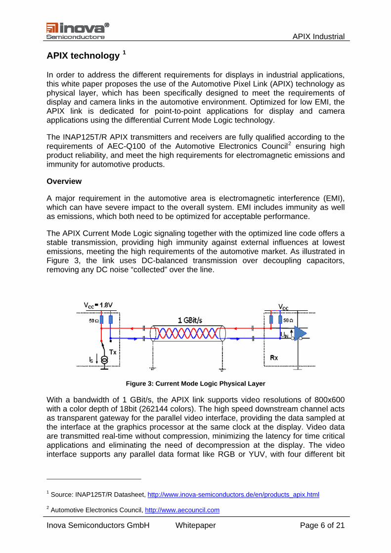
The APIX Current Mode Logic signaling together with the optimized line code offers a stable transmission, providing high immunity against external influences at lowest emissions, meeting the high requirements of the automotive market. As illustrated in Figure 3, the link uses DC-balanced transmission over decoupling capacitors, removing any DC noise “collected” over the line.
Figure 3: Current Mode Logic Physical Layer
With a bandwidth of 1 GBit/s, the APIX link supports video resolutions of 800x600 with a color depth of 18bit (262144 colors). The high speed downstream channel acts as transparent gateway for the parallel video interface, providing the data sampled at the interface at the graphics processor at the same clock at the display. Video data are transmitted real-time without compression, minimizing the latency for time critical applications and eliminating the need of decompression at the display. The video interface supports any parallel data format like RGB or YUV, with four different bit
1 Source: INAP125T/R Datasheet, http://www.inova-semiconductors.de/en/products_apix.html
2 Automotive Electronics Council, http://www.aecouncil.com
Inova Semiconductors GmbH Whitepaper Page 6 of 21
APIX Industrial
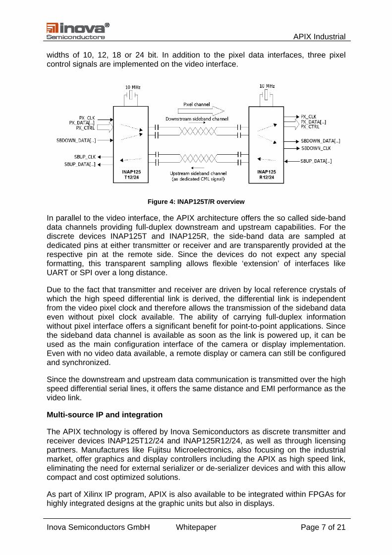
widths of 10, 12, 18 or 24 bit. In addition to the pixel data interfaces, three pixel control signals are implemented on the video interface.
Figure 4: INAP125T/R overview
In parallel to the video interface, the APIX architecture offers the so called side-band data channels providing full-duplex downstream and upstream capabilities. For the discrete devices INAP125T and INAP125R, the side-band data are sampled at dedicated pins at either transmitter or receiver and are transparently provided at the respective pin at the remote side. Since the devices do not expect any special formatting, this transparent sampling allows flexible ‘extension’ of interfaces like UART or SPI over a long distance.
Due to the fact that transmitter and receiver are driven by local reference crystals of which the high speed differential link is derived, the differential link is independent from the video pixel clock and therefore allows the transmission of the sideband data even without pixel clock available. The ability of carrying full-duplex information without pixel interface offers a significant benefit for point-to-point applications. Since the sideband data channel is available as soon as the link is powered up, it can be used as the main configuration interface of the camera or display implementation. Even with no video data available, a remote display or camera can still be configured and synchronized.
Since the downstream and upstream data communication is transmitted over the high speed differential serial lines, it offers the same distance and EMI performance as the video link.
Multi-source IP and integration
The APIX technology is offered by Inova Semiconductors as discrete transmitter and receiver devices INAP125T12/24 and INAP125R12/24, as well as through licensing partners. Manufactures like Fujitsu Microelectronics, also focusing on the industrial market, offer graphics and display controllers including the APIX as high speed link, eliminating the need for external serializer or de-serializer devices and with this allow compact and cost optimized solutions.
As part of Xilinx IP program, APIX is also available to be integrated within FPGAs for highly integrated designs at the graphic units but also in displays.
Inova Semiconductors GmbH Whitepaper Page 7 of 21

APIX Industrial
Single cable connection
An APIX link requires a maximum of 2 pairs of shielded twisted wires, transporting the “downstream” video and data stream at one pair, the “upstream” at the other pair.
Due to the AC-coupling of the APIX physical layer, the data lines can also be used for supplying the remote system. The power supply is realized by using either one or both existing wire pairs, with inductors acting as low pass filters to the signal lines. Since typically 2 pairs of wires are used, it is recommended to use the high speed downstream line for power, while the other one is used for ground.
With this, a display can be supplied with video, data communication and power over 2 pairs of wires.
Figure 5: Power over APIX
Cable selection
The APIX Link, as any other differential technology, requires a twisted pair cable, to ensure that “positive” and “negative” current of the differential signal negate as good as possible. The better the continuous cable impedance of 100Ohm and the more even the “twisting”, the higher the maximum distance possible with the cable.
Cable shielding
An important aspect for the distance but also susceptibility is the shielding. Unshielded cables provide the benefit of high flexibility and thin diameter of the cable, at relatively low cost. Since there is no additional shield, the cables have shown low attenuation and therefore may offer higher transmission distances than shielded cables. However, the signal is not protected against external noise or interference from the other pairs of wires which can have negative effect at the signal quality and therefore the distance. The EMI performance of unshielded cables is low, as any common noise coupling onto the lines (e.g. by local power supplies) is directly radiated, may cause link issues or affects surrounding devices.
Inova Semiconductors GmbH Whitepaper Page 8 of 21

APIX Industrial
In order to fulfill the requirements for EMI, it is recommended to use shielded twisted pair cables, which are slightly thicker and less flexible than unshielded cables. There are different kinds of shielded cables, varying in the shielding of the pairs (U/STP) or outer metal shielding, covering the entire group of cables (S/UTP), or a combination of both (S/STP or S/FTP). The terms S or F reflects either “screened” or “foiled” shielding, which blocks either high frequency or low frequency noise, which is also available in combination (SF/FTP).
Figure 6: Different cabling shieldings
Shielded twisted pair cables are available for different standards like Ethernet or USB, or for specific requirements as for example in the automotive area.
Standard CAT5 cables
The standard Ethernet cable CAT5, which is available as shielded or unshielded version, offers 4 differential pairs of wires, enabling the transmission of APIX downstream and upstream. The remaining 2 pairs are available for any signaling like power supply or another data bus, which offers high flexibility for different scenarios.
CAT5 cables offer the advantage to be available from many vendors at relatively low cost, with a small diameter of the cables. However, the quality of CAT5 cables may vary between different vendors, which can cause unreliable results for the maximum transmission length. Therefore it is recommended to test the desired cables and vendors, if distances like 15 or 20 meters are necessary and need to be guaranteed.
Optimized cables
Since APIX only requires 2 pairs of wires for video, data and power, it is possible to use cables, specifically optimized for differential signaling at 2 pairs. One example would be cables using “star-quad topology”, offering “high crosstalk attenuation and at the same time the cable is as compact as possible. Maximum crosstalk attenuation is necessary to be able to transmit broadband data streams on the two wire pairs independently of one another and without harmful interference between them" 3. Due to the high quality requirements, the cost of those cables may be higher than standard CAT5 cables.
Figure 7: Star-quad cable1
3 Source: „RosenbergerHSD® – The concept“, Rosenberger GmbH, http://www.rosenberger.de
Inova Semiconductors GmbH Whitepaper Page 9 of 21

APIX Industrial
Connector selection
The selection of connectors and plugs are as important as the cable in terms of EMI and impedance.
RJ45 Connector
One of the most common connectors for Ethernet applications is the RJ45 connector, used with CAT5 cables. The connector offers the benefit to be available as plastic version or surrounded by a metal case for better EMI shielding. RJ45 connectors are specified with high contact durability, which allows many and flexible installations.
Figure 8: RJ45 differential pairs
Rosenberger HSD connector 4
Similar to cables, connector manufacturers offer specific types of plugs and connectors, optimized for robustness or even differential signaling. Another example from the automotive area is the Rosenberger HSD® connector (High Speed Data Systems), which is popular for display links in cars. The HSD connector is based on the “star-quad” concept, to ensure high cross-talk attenuation throughout the plug and the connector to the cable. The HSD concept is optimized for high robustness in terms of connector/plug stability. The connectors are delivered already assembled with the cable to guarantee the high signal quality.
Figure 9: RosenbergerHSD® data pairs
The HSD connectors together with the star-quad cable support full APIX functionality, carrying the downstream and upstream of the APIX link, also allowing to transmit power supply over the same cable.
Figure 10: RosenbergerHSD and RJ45 connector
4 Source: „RosenbergerHSD® – The concept“, Rosenberger GmbH, http://www.rosenberger.de
Inova Semiconductors GmbH Whitepaper Page 10 of 21

APIX Industrial
APIX Industrial
In order to support the independent development of display and graphics unit, it is necessary to “standardize” the connector pinouts, as well as to agree on the configuration of the APIX link itself. The following sections provide proposals for different connectors as well as the configuration of the APIX link.
Standard connector pinout
The following tables include pinout proposals, based on the RJ45 and the Rosenberger HSD connector, allowing to address different application requirements.
The basic RJ45 connector pinout offers the following possibilites - High speed video link - Robust communication channel (Sideband) - Power supply over the data lines - Additional Power supply capability - 2 additional lines for synchronous data transfer (like display DDC data)
Since only the APIX pinout is mandatory, the pinout allows certain flexibility for different applications how to use the optional pins. E.g. the 4 pins may also be used for a USB connection. Another option is the value of the voltage, transmitted as “Power over APIX” (PoA).
Please refer to Appendix A for different usage scenarios for RJ45 connectors.
RJ45 Pin Signals APIX Transmitter APIX Receiver
Pin 1 Video+ / PoA+ SDOUT+ SDIN+
Pin 2 Video- / PoA+ SDOUT- SDIN-
Pin 3 (optional)
Pin 4 Upstream+ / PoA- SDIN+ SDOUT+
Pin 5 Upstream- / PoA- SDIN- SDOUT-
Pin 6 (optional)
Pin 7 (optional)
Pin 8 (optional) Table 1: RJ45 pinout
Inova Semiconductors GmbH Whitepaper Page 11 of 21
APIX Industrial
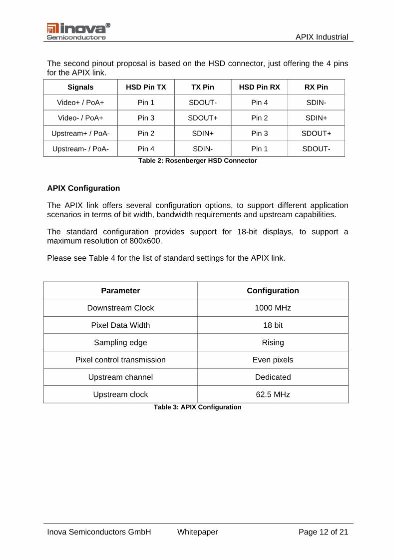
The second pinout proposal is based on the HSD connector, just offering the 4 pins for the APIX link.
Signals HSD Pin TX TX Pin HSD Pin RX RX Pin
Video+ / PoA+ Pin 1 SDOUT- Pin 4 SDIN-
Video- / PoA+ Pin 3 SDOUT+ Pin 2 SDIN+
Upstream+ / PoA- Pin 2 SDIN+ Pin 3 SDOUT+
Upstream- / PoA- Pin 4 SDIN- Pin 1 SDOUT- Table 2: Rosenberger HSD Connector
APIX Configuration
The APIX link offers several configuration options, to support different application scenarios in terms of bit width, bandwidth requirements and upstream capabilities.
The standard configuration provides support for 18-bit displays, to support a maximum resolution of 800x600.
Please see Table 4 for the list of standard settings for the APIX link.
Parameter Configuration
Downstream Clock 1000 MHz
Pixel Data Width 18 bit
Sampling edge Rising
Pixel control transmission Even pixels
Upstream channel Dedicated
Upstream clock 62.5 MHz Table 3: APIX Configuration
Inova Semiconductors GmbH Whitepaper Page 12 of 21

APIX Industrial
Pin Mapping
PX_DATA0 Red 0
PX_DATA1 Red 1
PX_DATA2 Red 2
PX_DATA3 Red 3
PX_DATA4 Red 4
PX_DATA5 Red 5
PX_DATA6 Green 0
PX_DATA7 Green 1
PX_DATA8 Green 2
PX_DATA9 Green 3
PX_DATA10 Green 4
PX_DATA11 Green 5
PX_DATA12 Blue 0
PX_DATA13 Blue 1
PX_DATA14 Blue 2
PX_DATA15 Blue 3
PX_DATA16 Blue 4
PX_DATA17 Blue 5
PX_DATA18
PX_DATA19
PX_DATA20
PX_DATA21
PX_DATA22
PX_DATA23
PX_CTRL0 HSYNC
PX_CTRL1 VSYNC
PX_CTRL2 DE
Table 4: INAP125T/R color and control bit mapping
Inova Semiconductors GmbH Whitepaper Page 13 of 21
APIX Industrial
Outlook
The fast developments in the display market to further increase display size and resolutions, also asks for faster digital display links. High resolutions like 1280x1024 or higher require link speeds of 3GBit/s and beyond. In order to fulfill the requirements of these high resolution displays, the APIX technology is currently “enhanced” to be able to transmit up to 3GBit/s of video data at a single pair of differential wires. The first implementations will be fully backwards compatible, to allow to connect to existing INAP125 or third party devices.
With this, the APIX technology offers a single cable solution for existing and future display products.
Conclusion
With selecting the APIX as physical layer, remote displays can be driven by a single cable, carrying the high speed video stream, in parallel to touch screen or control information. The device, as well as the differential Current Mode Logic provides lowest EMI over a distance of up to 20 meters. APIX can be transmitted at 4 wires of a standard CAT5 cables, allowing the reuse of existing cabling, with the option of power suppliy or other data communication over the same cable.
Inova Semiconductors GmbH Whitepaper Page 14 of 21

APIX Industrial
Author
Markus Römer is technical sales manager at Inova Semiconductors GmbH, responsible for technical support and sales of the Gigabit/s serial data communication products.
Inova Semiconductors GmbH
INOVA Semiconductors, an ISO9001 certified company, is a fab-less semiconductor manufacturer. The headquarters of the company is located in Munich, Germany. It is designing, marketing and selling its products and licensing technologies, directly and through a global network of distributors. INOVA Semiconductors specializes in reliable high speed serial data communication products for Gigabit/s data transfers through standard STP copper cables up to 50 m, or through fiber optic cables up to 500 m and more. GigaSTaR™, GigaSTaR DDL™ and APIX™ product lines have achieved major advancements in digital multimedia transmission particularly in the Automotive, Industrial and Transportation markets. Website: http://www.inova-semiconductors.de
is a registered trademark of Inova Semiconductors GmbH
I²C is a registered trademark of Philips Corporation
All other referenced brands, product names, service names and trademarks are property of their respective holders
Inova Semiconductors GmbH Whitepaper Page 15 of 21
APIX Industrial
Appenix A – Connection Scenarios
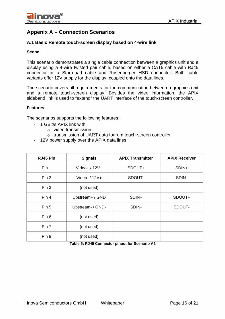
A.1 Basic Remote touch-screen display based on 4-wire link
Scope
This scenario demonstrates a single cable connection between a graphics unit and a display using a 4-wire twisted pair cable, based on either a CAT5 cable with RJ45 connector or a Star-quad cable and Rosenberger HSD connector. Both cable variants offer 12V supply for the display, coupled onto the data lines.
The scenario covers all requirements for the communication between a graphics unit and a remote touch-screen display. Besides the video information, the APIX sideband link is used to “extend” the UART interface of the touch-screen controller.
Features
The scenarios supports the following features: - 1 GBit/s APIX link with
o video transmission o transmission of UART data to/from touch-screen controller
- 12V power supply over the APIX data lines
RJ45 Pin Signals APIX Transmitter APIX Receiver
Pin 1 Video+ / 12V+ SDOUT+ SDIN+
Pin 2 Video- / 12V+ SDOUT- SDIN-
Pin 3 (not used)
Pin 4 Upstream+ / GND SDIN+ SDOUT+
Pin 5 Upstream- / GND- SDIN- SDOUT-
Pin 6 (not used)
Pin 7 (not used)
Pin 8 (not used)
Table 5: RJ45 Connector pinout for Scenario A2
Inova Semiconductors GmbH Whitepaper Page 16 of 21

APIX Industrial
Figure 11: Connection diagram for scenario A1, with RJ45 connector
Signals HSD Pin TX TX Pin HSD Pin RX RX Pin
Video+ / PoA+ Pin 1 SDOUT- Pin 4 SDIN-
Video- / PoA+ Pin 3 SDOUT+ Pin 2 SDIN+
Upstream+ / PoA- Pin 2 SDIN+ Pin 3 SDOUT+
Upstream- / PoA- Pin 4 SDIN- Pin 1 SDOUT-
Table 6: Rosenberger HSD Connector pinout
Figure 12: Connection diagram for scenario A1, with Rosenberger HSD
Inova Semiconductors GmbH Whitepaper Page 17 of 21

APIX Industrial
A.2 Remote touch-screen display with 12V power and DDC
Scope
This scenario demonstrates a single cable connection between a graphics unit and a display using a CAT5 cable with RJ45 connector, offering 5V supply for the display. For flexible power supply structure, the link offers an additional 12V supply at separate wires. In order to support DDC (display data channel) information to be transmitted directly over the cable, e.g. supporting a local I²C EEPROM, the remaining pair is used for data and clock of an I²C like interface.
The scenario covers all requirements for the communication between a graphics unit and a remote touch-screen display. Besides the video information, the APIX link is used to “extend” the UART interface of the touch-screen controller.
NOTE: Since the I²C bus is transmitted as is, without differential signaling, it will be susceptible to noise and may generate electromagnetic emissions at the cable.
Features
The scenarios supports the following features: - 1 GBit/s APIX link with
o video transmission o transmission of UART data to/from touch-screen controller
- 5V power supply over the APIX data lines - 12V Auxiliary Power supply - I²C like interface for DDC Information
RJ45 Pin Signals APIX Transmitter APIX Receiver
Pin 1 Video+ / 5V+ SDOUT+ SDIN+
Pin 2 Video- / 5V+ SDOUT- SDIN-
Pin 3 +12V
Pin 4 Upstream+ / GND SDIN+ SDOUT+
Pin 5 Upstream- / GND- SDIN- SDOUT-
Pin 6 GND (12V)
Pin 7 I²C Clock
Pin 8 I²C Data
Table 7: RJ45 Connector pinout for Scenario A2
Inova Semiconductors GmbH Whitepaper Page 18 of 21

APIX Industrial
Figure 13: Connection diagram for scenario 2
Inova Semiconductors GmbH Whitepaper Page 19 of 21

APIX Industrial
A.3 Remote touch-screen display with USB connection
Scope
This scenario demonstrates a single cable connection between a graphics unit and a display using a CAT5 cable with RJ45 connector, offering 5V supply for the display. The remaining pins are used for the 4 wires of a USB connection, basically extending the USB connection to the host.
This scenario shall be seen as basic proposal, as the USB specification defines a maximum of 5 meters for the cable length. There are various solutions on the market for extending a USB link, which may be used in the application but since they will not affect the actual connector pinout or APIX functionality, will not be discussed further in this document.
Features
The scenarios supports the following features: - 1 GBit/s APIX link with
o video transmission o transmission of UART data to/from touch-screen controller
- 5V power supply over the APIX data lines - USB plug at display
RJ45 Pin Signals APIX Transmitter APIX Receiver
Pin 1 Video+ / 5V+ SDOUT+ SDIN+
Pin 2 Video- / 5V+ SDOUT- SDIN-
Pin 3 VBUS
Pin 4 Upstream+ / GND SDIN+ SDOUT+
Pin 5 Upstream- / GND- SDIN- SDOUT-
Pin 6 GND (USB)
Pin 7 USB D+
Pin 8 USB D-
Table 8: RJ45 Connector for Scenario A1
Inova Semiconductors GmbH Whitepaper Page 20 of 21

APIX Industrial
Inova Semiconductors GmbH Whitepaper Page 21 of 21
Figure 14: Connection diagram for scenario 2