Api rp 540 electrical installations in peutroleum plants
107
Electrical Installations in Petroleum Processing Plants API RECOMMENDED PRACTICE 540 FOURTH EDITION, APRIL 1999 Environmental Partnwsbìp American Petroleum Institute Helping You Get The Job Done Right? Reproduced by IHS under license with API Document provided by IHS Licensee=BG Group/5943895100, 01/31/2005 04:58:30 MST at 303-397-2295. --`,`,,,`,`,`,,,```,,``,,`,``,,-`-`,,`,,`,`,,`---
description
Â
Transcript of Api rp 540 electrical installations in peutroleum plants
Electrical Installations in Petroleum Processing Plants
API RECOMMENDED PRACTICE 540 FOURTH EDITION, APRIL 1999
Environmental Partnwsbìp
American Petroleum Institute
Helping You Get The Job Done Right?
Copyright American Petroleum Institute Reproduced by IHS under license with API
Document provided by IHS Licensee=BG Group/5943895100, 01/31/2005 04:58:30 MSTQuestions or comments about this message: please call the Document Policy Groupat 303-397-2295.
--`,`,,,`,`,`,,,```,,``,,`,``,,-`-`,,`,,`,`,,`---
&$- Strategies for Today’s
Environmental Pavtnersbip
API ENVIRONMENTAL, HEALTH AND SAFETY MISSION AND GUIDING PRINCIPLES
The members of the American Petroleum Institute are dedicated to continuous efforts to improve the compatibility of our operations with the environment while economically developing energy resources and supplying high quality products and services to consum- ers. We recognize our responsibility to work with the public, the government, and others to develop and to use natural resources in an environmentally sound manner while protecting the health and safety of our employees and the public. To meet these responsibilities, API members pledge to manage our businesses according to the following principles using sound science to prioritize risks and to implement cost-effective management practices:
e
e
e
e
e
e
e
e
e
e
e
To recognize and to respond to community concerns about our raw materials, prod- ucts and operations. To operate our plants and facilities, and to handle our raw materials and products in a manner that protects the environment, and the safety and health of our employees and the public. To make safety, health and environmental considerations a priority in our planning, and our development of new products and processes.
To advise promptly, appropriate officials, employees, customers and the public of information on significant industry-related safety, health and environmental hazards, and to recommend protective measures.
To counsel customers, transporters and others in the safe use, transpqrtation and dis- posal of our raw materials, products and waste materials. To economically develop and produce natural resources and to conserve those resources by using energy efficiently. To extend knowledge by conducting or supporting research on the safety, health and environmental effects of our raw materials, products, processes and waste materials.
To commit to reduce overall emissions and waste generation. To work with others to resolve problems created by handling and disposal of hazard- ous substances from our operations. To participate with government and others in creating responsible laws, regulations and standards to safeguard the community, workplace and environment. To promote these principles and practices by sharing experiences and offering assis- tance to others who produce, handle, use, transport or dispose of similar raw materi- als, petroleum products and wastes.
Copyright American Petroleum Institute Reproduced by IHS under license with API
Document provided by IHS Licensee=BG Group/5943895100, 01/31/2005 04:58:30 MSTQuestions or comments about this message: please call the Document Policy Groupat 303-397-2295.
--`,`,,,`,`,`,,,```,,``,,`,``,,-`-`,,`,,`,`,,`---
~~ ~~
~
STD-API/PETRO RP 540-EN.GL 1999 I 073i?;390 Ob15533 928 m-,
Electrical Installations in Petroleum Processing Plants
Downstream Segment
API RECOMMENDED PRACTICE 540 FOURTH EDITION, APRIL 1999
American Petroleum Institute
Helping You Get The Job Done R¡ght.SM
Copyright American Petroleum Institute Reproduced by IHS under license with API
Document provided by IHS Licensee=BG Group/5943895100, 01/31/2005 04:58:30 MSTQuestions or comments about this message: please call the Document Policy Groupat 303-397-2295.
--`,`,,,`,`,`,,,```,,``,,`,``,,-`-`,,`,,`,`,,`---
SPECIAL NOTES
API publications necessarily address problems of a general nature. With respect to partic- ular circumstances, local, state, and federal laws and regulations should be reviewed.
API is not undertaking to meet the duties of employers, manufacturers, or suppliers to warn and properly train and equip their employees, and others exposed, concerning health and safety lisks and precautions, nor undertaking their obligations under local, state, or fed- eral laws.
Information concerning safety and health risks and proper precautions with respect to par- ticular materials and conditions should be obtained from the employer, the manufacturer or supplier of that material, or the material safety data sheet.
Nothing contained in any API publication is to be construed as granting any right, by implication or otherwise, for the manufacture, sale, or use of any method, apparatus, or prod- uct covered by letters patent. Neither should anything contained in the publication be con- strued as insuring anyone against liability for infringement of letters patent.
Generally, API standards are reviewed and revised, reaffirmed, or withdrawn at least every five years. Sometimes a one-time extension of up to two years will be added to this review cycle. This publication will no longer be in effect five years after its publication date as an operative API standard or, where an extension has been granted, upon republication. Status of the publication can be ascertained from the API Downstream Segment [telephone (202) 682-8000]. A catalog of API publications and materials is published annually and updated quarterly by API, 1220 L Street, N.W., Washington, D.C. 20005.
This document was produced under API standardization procedures that ensure appropri- ate notification and participation in the developmental process and is designated as an API standard. Questions concerning the interpretation of the content of this standard or com- ments and questions concerning the procedures under which this standard was developed should be directed in writing to the director of the Downstream Segment, American Petro- leum Institute, 1220 L Street, N.W., Washington, D.C. 20005. Requests for permission to reproduce or translate all or any part of the material published herein should also be addressed to the director.
API standards are published to facilitate the broad availability of proven, sound engineer- ing and operating practices. These standards are not intended to obviate the need for apply- ing sound engineering judgment regarding when and where these standards should be utilized. The formulation and publication of A P I standards is not intended in any way to inhibit anyone from using any other practices.
Any manufacturer marking equipment or materials in conformance with the marking requirements of an API standard is solely responsible for complying with all the applicable requirements of that standard. API does not represent, warrant, or guarantee that such prod- ucts do in fact conform to the applicable API standard. .
All rights reserved. No part of this work may be reproduced, stored in a retrieval system, or transmitted by any means, electronic, mechanical, photocopying, recording, or otherwise,
without prior written permission jìom the publishel: Contact the Publisher API Publishing Services, 1220 L Street, N. W , Washington, D.C. 20005.
Copyright O 1999 American Petroleum Institute
L!
Copyright American Petroleum Institute Reproduced by IHS under license with API
Document provided by IHS Licensee=BG Group/5943895100, 01/31/2005 04:58:30 MSTQuestions or comments about this message: please call the Document Policy Groupat 303-397-2295.
--`,`,,,`,`,`,,,```,,``,,`,``,,-`-`,,`,,`,`,,`---
FOREWORD
This recommended practice provides information on electrical installations in petroleum facilities. It is intended for all individuals and organizations concerned with the safe design, installation, and operation of electrical systems in petroleum facilities.
This recommended practice has been developed by individuals with many years’ experi- ence in the petroleum industry. Although of interest to anyone seeking information on elec- trical systems in petroleum facilities, it is primarily intended to be used by individuals knowledgeable in engineering fundamentals who require specific guidance concerning cur- rently accepted practices in the petroleum industry.
API publications may be used by anyone desiring to do so. Every effort has been made by the Institute to assure the accuracy and reliability of the data contained in them; however, the Institute makes no representation, warranty, or guarantee in connection with this publication and hereby expressly disclaims any liability or responsibility for loss or damage resulting from its use or for the violation of any federal, state, or municipal regulation with which this publication may conflict.
Suggested revisions are invited and should be submitted to the director of the Downstream Segment, American Petroleum Institute, 1220 L Street, N.W., Washington, D.C. 20005.
iii
Copyright American Petroleum Institute Reproduced by IHS under license with API
Document provided by IHS Licensee=BG Group/5943895100, 01/31/2005 04:58:30 MSTQuestions or comments about this message: please call the Document Policy Groupat 303-397-2295.
--`,`,,,`,`,`,,,```,,``,,`,``,,-`-`,,`,,`,`,,`---
IMPORTANT INFORMATION CONCERNING USE OF ASBESTOS OR ALTERNATIVE MATERIALS
Asbestos is specified or referenced for certain components of the equipment described in some API standards. It has been of extreme usefulness in minimizing fire hazards associated with petroleum processing. It has also been a universal sealing material, compatible with most refining fluid services.
Certain serious adverse health effects are associated with asbestos, among them the serious and often fatal diseases of lung cancèr, asbestosis, and mesothelioma (a cancer of the chest and abdominal linings). The degree of exposure to asbestos varies with the prod- uct and the work practices involved.
Consult the most recent edition of the Occupational Safety and Health Administration (OSHA), U.S. Department of Labor, Occupational Safety and Health Standard for Asbestos, Tremolite, Anthophyllite, and Actinolite, 29 Code of Federal Regulations Section 1910.1001; the U.S. Environmental Protection Agency, National Emission Standard for Asbestos, 40 Code of Federal Regulations Sections 61.140 through 61.156; and the U.S. Environmental Protection Agency (EPA) rule on labeling requirements and phased banning of asbestos products (Sections 763.160-179).
There are currently in use and under development a number of substitute materials to replace asbestos in certain applications. Manufacturers and users are encouraged to develop and use effective substitute materials that can meet the specifications for, and operating requirements of, the equipment to which they would apply.
SAFETY AND HEALTH INFORMATION WITH RESPECT TO PARTICULAR PRODUCTS OR MATERTALS CAN BE OBTAINED FROM THE EMPLOYER, THE MANUFACTURER OR SUPPLIER OF THAT PRODUCT OR MATERIAL,, OR THE MATERIAL SAFETY DATA SHEET.
Copyright American Petroleum Institute Reproduced by IHS under license with API
Document provided by IHS Licensee=BG Group/5943895100, 01/31/2005 04:58:30 MSTQuestions or comments about this message: please call the Document Policy Groupat 303-397-2295.
--`,`,,,`,`,`,,,```,,``,,`,``,,-`-`,,`,,`,`,,`---
CONTENTS
Page
1 INTRODUCTION . . . . . . . . . . . . . . . . . . . . . . . . . . . . . . . . . . . . . . . . . . . . . . . . . . . . . . 1 1.1 Purpose .......................................................... 1 1.2 Scope ........................................................... 1 1.3 References ....................................................... 1
2 CLASSIFED LOCATIONS OR ELECTRICAL EQUIPMENT. . . . . . . . . . . . . . . . . 5 2.1 Purpose .......................................................... 5 2.2 Scope ............................................................ 5 2.3 Classification of Flammable and Combustible Liquids and Gases . . . . . . . . . . . 5 2.4 Classification of Locations .......................................... 5 2.5 Electrical Equipment for Classified Locations ........................... 6 2.6 Alternative Design in Classified Locations .............................. 6
3 ELECTRICAL ENERGY EFFICIENCY .................................... 9 3.1 Purpose .......................................................... 9 3.2 Scope ........................................................... 9 3.3 The Role of Electrical Efficiency ..................................... 9 3.4 Definition of Efficiency ............................................. 9 3.5 Specification Considerations ......................................... 9 3.6 Economic Evaluation ............................................... 9 3.7 Cogeneration and Energy Recovery .................................. 10 3.8 Design Considerations ............................................. 12 3.9 Relationship to Power Factor ........................................ 15 3.10 Definitions and Conversion Factors ................................... 15
4 FACILITY POWER SYSTEMS .......................................... 17
4.2 Scope .......................................................... 17 4.3 Power Sources .................................................... 17
4.5 Power System Arrangements ........................................ 23
4.1 Purpose ......................................................... 17
4.4 System Voltagès .................................................. 22
4.6 Power System Studies ............................................. 23 4.7 System Protection ................................................ 26 4.8 Fuses ........................................................... 27 4.9 Circuit Breakers .................................................. 28 4.10 Switchgear ...................................................... 28 4.11 Transformers .................................................... 29 4.12 Overhead Electric Power Distribution ................................. 33
5 GROUNDING AND LIGHTNING PROTECTION .......................... 35 5.1 Purpose ......................................................... 35 5.2 Scope .......................................................... 35 5.3 Static Electricity and Stray Currents .................................. 35 5.4 SystemGrounding ................................................ 35 5.5 Eiquipment Grounding ............................................. 36 5.6 Connections to Earth .............................................. 38 5.7 Lightning Protection .............................................. 38
6 MOTORS AND CONTROLLERS ........................................ 41 6.1 Purpose ......................................................... 41
V
Copyright American Petroleum Institute Reproduced by IHS under license with API
Document provided by IHS Licensee=BG Group/5943895100, 01/31/2005 04:58:30 MSTQuestions or comments about this message: please call the Document Policy Groupat 303-397-2295.
--`,`,,,`,`,`,,,```,,``,,`,``,,-`-`,,`,,`,`,,`---
Page
6.2 Scope ............................................................ 41 6.3 Motor Rating and Efficiency ........................................ 41 6.4 Relative Locations of Motors and Controllers .......................... 41 6.5 Frequencies ...................................................... 41 6.6 Standard Voltage for Motors ........................................ 41 6.7 Motor Voltage Selection ............................................ 41 6.8 Temperature and Altitude Considerations in Motor Applications . . . . . . . . . . . 42 6.9 Other Conditions Affecting Design and Application ..................... 42 6.10 Types of Motor Construction ........................................ 42 6.11 Installation ...................................................... 45 6.12 Construction of Totally Enclosed Motors .............................. 45 6.13 Motors for Class I Locations ........................................ 46 6.14 Motors for Class II Locations ....................................... 47 6.15 Motor Service Factor .............................................. 48 6.16 Frequency of Starting .............................................. 48 6.17 Temperature. Vibration, and Current Indicators ......................... 48 6.18 -Conduit or Terminal Box ........................................... 48 6.19 Space Heaters ..................... L .............................. 48 6.20 Bearings and Lubrication ........................................... 49 6.21 Torque Requirements .............................................. 50 6.22 Method of Starting ................................................ 52
6.24 Application of Motor Control ....................................... 60 6.23 Motor Controllers ................................................. 55
6.25 Means of Disconnection ........................................... 61 6.26 Coordination of Controller Applications With Fuses or Circuit Breakers On
Low-Voltage Systems ............................................. 61 6.27 Overload Protection: Special Applications ............................. 62 6.28 Voltage Limitations ............................................... 62 6.29 Application of Outdoor and Indoor Types ............................. 62 6.30 Pushbutton Stations ............................................... 62 6.3 1 Additional References ............................................. 63
7 LIGHTING .......................................................... 65 7.1 Purpose ......................................................... 65 7.2 Scope .......................................................... 65 7.3 Definition of Terms ............................................... 65 7.4 Lighting Facilities ................................................ 65 7.5 Luminaires ...................................................... 70 7.6 Light Quality .................................................... 71 7.7 nluminance ...................................................... 71 7.8 Installation Initial Values ........................................... 72 7.9 Lighting System Power Supply ....................................... 72 7.10 Emergency Lighting ............................................... 72 7.1 1 Design Considerations ............................................. 73 7.12 Estimating Electric Power Requirements ............................... 73 7.13 Illuminance Meters ............................................... 74
8 WIRING ............................................................. 75 8. 1 Purpose .......................................................... 75 8.2 Scope .......................................................... 75 8.3 General .......................................................... 75 8.4 Conduit Systems ................................................. 75 8.5 Electrical Metallic Tubing .......................................... 79
i
vi
Copyright American Petroleum Institute Reproduced by IHS under license with API
Document provided by IHS Licensee=BG Group/5943895100, 01/31/2005 04:58:30 MSTQuestions or comments about this message: please call the Document Policy Groupat 303-397-2295.
--`,`,,,`,`,`,,,```,,``,,`,``,,-`-`,,`,,`,`,,`---

Page 8.6 Busways ........................................................ 79 8.7 Wireways ....................................................... 79 8.8 Cable Trays ..................................................... 80 8.9 Manholes and Above Grade Pull Points ............................... 80 8.10 Wire and Cable ................................................... 81 8.11 Fireproofing ..................................................... 85
9 POWER SYSTEMS FOR INSTRUMENTATION AND PROCESS CONTROL . . 87 9.1 Purpose ..................... : ................................... 87 9.2 Scope .......................................................... 87 9.3 Basic Design Criteria .............................................. 87 9.4 Design Considerations ............................................. 87 9.5 Electric Power Systems ............................................ 89 9.6 Distribution System ............................................... 90 9.7 Wiring Methods .................................................. 92 9.8 System and Equipment Grounding ................................... 92 9.9 Considerations for Classified Locations ............................... 92
10 SPECIALEQUIPMENT ................................................ 93 10.1 Purpose ........................................................ 93 10.2 Scope ......................................................... 93 10.3 General ........................................................ 93 10.4 Communication Systems .......................................... 93 10.5 Supervisory Control and Data Acquisition Equipment (SCADA) . . . . . . . . . . 93 10.6 Closed-Circuit Television (CCTV) .................................. 94 10.7 Obstruction and Warning Lighting ................................... 94 10.8 Navigation Lighting .............................................. 94 10.9 Fire Alarm Systems .............................................. 94 10.10 Electric Heat Tracing ............................................. 94 10.1 1 Cathodic Protection Systems ....................................... 94 10.12 Desalters and Precipitators ........................................ 94 1 O . 13 Portable Equipment .............................................. 95
1 1 INHERENT ELECTRICAL SAFETY ..................................... 97 11.1 General ......................................................... 97 11.2 References ...................................................... 97 11.3 Specifics ......................................................... 97
APPENDIX A INFORMATIVE ANNEX A ................................ 99
Figures 1 Brayton Cogeneration Cycle .......................................... 11 2 Carnot Topping Cycle ............................................... 11 3 System Energy Losses: Adjustable Speedversus Throttling . . . . . . . . . . . . . . . . . 14 4 Power Relationship ................................................. 15 5 Single Main Bus Arrangement ........................................ 18 6 Unit Construction Bus Arrangement ................................... 18 7 Synchronizing Bus Arrangement .... ................................. 19 8 Purchased Power: Divided Feeder Operation ............................. 20 9 Purchased Power: Parallel Feeder Operation ............................. 20 10 Simple Radial System ............................... ; ............... 24
v i
Copyright American Petroleum Institute Reproduced by IHS under license with API
Document provided by IHS Licensee=BG Group/5943895100, 01/31/2005 04:58:30 MSTQuestions or comments about this message: please call the Document Policy Groupat 303-397-2295.
--`,`,,,`,`,`,,,```,,``,,`,``,,-`-`,,`,,`,`,,`---
STD;API/PETRO RP 540 ..- ENGL J977 . 0732290 Ob&5540 Obd I . .
11 12 13 14 15 16
17 18 19
20
21
Page
Primary-Selective Radial System ...................................... 24 Secondary-Selective Radial System .................................... 25
Combined Motor and Load Speed-Torque Curve ......................... 51 Typical Wiring Diagram for Full-Voltage Starting ......................... 53
Secondary-Selective Parallel System ................................... 25
Typical Wiring Diagram for Autotransformer Method of Reduced- Voltagestarting .................................................... 54 Typical Wiring.Diagram for Wound-Rotor Motor Control . . . . . . . . . . . . . . . . . . 55 Lighting System Power Supply Considerations ........................... 72 Typical Instrument Power Supplies: Standby Generator Not Required for Instrument Power ................................................ 90 Typical Instrument Power Supply: Standby Generator Required for Instrument Power .................................................. 90 Typical Instrument Power Supply with Supply Switching . . . . . . . . . . . . . . . . . . 91
Tables 1 Conditions Affecting Motor Design .................................... 43 2 Characteristic Torques ............................................... 50 3 NEMA Enclosure Types for AC Motor Controllers ........................ 58 4 Illuminances Currently Recommended for Petroleum. Chemical. and
Petrochemical Plants ................................................ 67 5 Temperature Marking Identification Numbers ............................ 71 6 Constants for Estimating Lighting Loads ................................ 73
viii
Copyright American Petroleum Institute Reproduced by IHS under license with API
Document provided by IHS Licensee=BG Group/5943895100, 01/31/2005 04:58:30 MSTQuestions or comments about this message: please call the Document Policy Groupat 303-397-2295.
--`,`,,,`,`,`,,,```,,``,,`,``,,-`-`,,`,,`,`,,`---
~~
STD.API/PETRO RP 540-ENGL 3999 D 0732290 Ob35543 TT4 E
Electrical Installations in Petroleum Processing Plants
SECTION 1-INTRODUCTION
1.1 PURPOSE
This recommended practice provides information on electrical installations in petroleum facilities. Petroleum processing requires specialized equipment that continually processes, often at high rates and elevated temperatures and pressures, liquids, and gases that undergo both chemical and physical changes. Consequently, it is necessary that electri- cal installations and equipment in petroleum facilities be designed to prevent accidental ignition of flammable liquids and gases.
To maintain safety and operating continuity, requirements for the electrical systems in petroleum facilities are more stringent than those for most other manufacturing facilities. This recommended practice addresses specific requirements fos those electrical systems.
1.2 SCOPE
This recommended practice is limited to electrical installa- tions in petroleum facilities. It provides a basis for specifica- tions included in engineering and construction contracts. Electrical equipment test standards are excluded from the scope of this recommended practice. Operation and mainte- nance are addressed only insofar as they affect electrical sys- tem design and electrical equipment selection. The subject of energy conservation is reviewed.
1.3 REFERENCES
1.3.1 The following standards, codes, and specifications are cited in this recommended practice:
A P I RP 14F Design and Installation of Electrical Sys-
tems for Offshore Production Plagoms KF' 500 Recommended Practice for Classification
of Locations for Electrical Installations at Petroleum Facilities Clussijìed as Class I, Division I and Division 2
RP 505 Recommended Practice for Classification of Locations for Electrical Installations at Petroleum Facilities Classijìed as Class I, Zone 0, Zone I , and Zone 2
Std 541 . Form-Wound Squirrel-Cage Induction Motors-250 Horsepower and Larger
Std 546 Brushless Synchronous Machines-500 kVA und Larger
RP 552 Recommended Practice for Transmission Systems
1
~~~ ~~ ~
Std 610
Std 614
RP 651
RP 2001 RP 2003
AEICl CS 1
CS5
CS6
AG MA^ 6019-E
ANSP C80.1
C80.5 C84.1
ASTM4 D877
CSAS
Centrifugal Pumps for Petroleum, .Heavy Duty Chemical and Gas Industry Service Lubrication, Shaft-Sealing, and Control-Oil Systems and Auxiliaries for Petroleum, Chemical and Gas Industry Service Cathodic Protection of Aboveground Stor- age Tanks Fire Protection in Rejìneries Protection Against Ignitions Arising out of Static, Lightning, and Stray Currents
Specijìcation for Impregnated Paper-lnsu- luted, Lead-Covered Cable, Solid Type Specifications for Thermoplastic and Crosslinked Polyethylene Insulated Shielded Power Cables Rated 5 Through 46 kV Specifications for Ethylene Propylene Rub- ber Insulated Shielded Power Cables Rated 5 Through 69 kV
Gearmotors Using Spul; Helical, Herring- bone, Straight Bevel, or Spiral Bevel Gears
Canadian Electrical Code
Specification for Rigid Steel Conduit, Zinc Coated Specification for Rigid Aluminum Conduit Electric Power Systems and Equipment Voltuge Ratings (60 Hz)
Standard Test Method for Dielectric Break- down Voltage of Insulating Liquids Using Disk Electrodes
'Association of Edison Rluminating Companies, P.O. Box 2641, Birmingham, Alabama 35291. 2American Gear Manufacturers Association, 1500 King Street, Suite 201, Alexandria, Virginia 22314. 3American National Standards Institute, 1430 Broadway, New York, New York 10018. 4American Society of Testing and Materials, 100 Barr Harbor Drive, West Conshohocken, Pennsylvania 19428-2959. 5Canadian Standards Association, 178 Rexdale Boulevard, Rexdale, Ontario M9W 1R3, Canada.
Copyright American Petroleum Institute Reproduced by IHS under license with API
Document provided by IHS Licensee=BG Group/5943895100, 01/31/2005 04:58:30 MSTQuestions or comments about this message: please call the Document Policy Groupat 303-397-2295.
--`,`,,,`,`,`,,,```,,``,,`,``,,-`-`,,`,,`,`,,`---
EPA~ 40 CFR Part 76 1
IEEE7 Std 32
Std 80
Std 100
Std 141
‘I Std 142
Std 242
Std 399
Std 422
Std 446
Std 493
Std 5 15
Std 518
Std 519
Std 576
“Polychlorinated Biphenyls (PCBs) Manu- facturing, . Processing, Distribution in Commerce,. and Use Prohibitions”
Standard Requirements, Terminology, and Test Procedures for Neutral Grounding Devices Guide for Safety in AC Substation Grounding Standard Dictionary of Electrical and Electronics Terms Recommended Practice for Electric Power Distribution for Industrial Plants (Red Book) Recommended Practice for Grounding of Industrial and Commercial Power Systems Recommended Practice for Protection and Coordination of Industriai and Commer- cial Power Systems p u f f Book) Recommended Practice for Industrial and Commercial Power Systems Analysis (Brown Book) Guide for the Design and Installation of Cable Systems in Power Generating Stations Recommended Practice for Emergency and Standby Power Systems for Industrial and Commercial Applications Recommended Practice for the Design of Reliable Industrial and Commercial Power System (Gold Book) Standard for the Testing, Design, Installation and Maintenance of Electrical Resistance Heat Tracing for Industrial Applications Guide for the Installation of Electrical Equipment to Minimize Noise Inputs to Controllers from External Sources Recommended Practice and Requirements for Harmonic Control in Electric Power Systems Recommended Practice for Installation, Termination, and Testing of Insulated Power Cable as Used in the Petroleum and Chemical Industry
Std 841
Std 844
Std 1015
Std 1100
c2 (37.12.00
(257.12.01
C57.92
(37.96
C57.106
(37.111
(37.121
NACE* RP 0169
F 3 0176
RP 0675
NEMA9 ICs 1
ICs 6
MG 1
Recommended Practice for Chemical Industry Severe Duty Squirrel-Cage Induc- tion Motors 600 Volts and Below Recommended Practice for Electrical Impedance, Induction, and Skin Effect Heating of Pipelines and Vessels ,
Recommended Practice for Applying LOW- Voltage Circuit Breakers Used in Indus- trial and Commercial Power Systems (Blue Book) Recommended Practice for Powering and Grounding Sensitive Electronic Equipment National Electrical Safety Code .
General Requirements for Liquid- Immersed Distribution, PoweK and Regu- lating Transformers Standard General Requirements for Dry- type Distribution and Power Transformers Including those with Solid-cast and/or Resin-encapsulated Windings Guide for Loading Mineral-oil-immersed Power Transfomers Up to and Including 100 MVA with 55°C or 65°C Average Winding Rise Guide for Loading Dry-Type Distribution and Power Transformers Guide for Acceptance and Maintenance of -- Insulating Oil in Equipment Guide for Acceptance of Silicone Insulat- ing Fluid and Its Maintenance in Transformers Guidt? for Acceptance and Maintenance of Less Flammable Hydrocarbon Fluid in Transfomers
Control of External Corrosion on Under- ground or Submerged Metallic Piping Systems Corrosion Control of Steel Fixed Wshore Platforms Associated with Petroleum Production Control of External Comsion on Offshore Steel Pipelines
General Standards for Industrial Control and Systems Enclosures for Industrial Controls and Systems Motors and Generators
6United States Environmental Protection Agency/National Center for Environmental Publications, P.O. Box 42419, Cincinnati, Ohio
71nstitute of Electrical and Electronics Engineers, 445 Hoes Lane, Piscataway, NJ 08855-1331.
45242-2419. 8NACE International, 1440 South Creek Drive, Houston, Texas 77084. gNational Electrical Manufacturers Association, 1300 North 17th Street, Suite 1847, Rosslyn, Viiginia 22209.
Copyright American Petroleum Institute Reproduced by IHS under license with API
Document provided by IHS Licensee=BG Group/5943895100, 01/31/2005 04:58:30 MSTQuestions or comments about this message: please call the Document Policy Groupat 303-397-2295.
--`,`,,,`,`,`,,,```,,``,,`,``,,-`-`,,`,,`,`,,`---
STD*API/PETRO RP 540-ENGL L999 M O732290 0615543 877 e
ELECTRICAL INSTALLATIONS IN PETROLEUM PROCESSING PLANTS 3
MG 2
WC 3
WC 5
WC 7
WC 8
NFPA'O
30 37
54 69 70 70E
77 90A
91
110 325
496
497
499
780
Safety Standard for Construction and Guide for Selection, Installation and Use of Electric Motors and Generators Rubber-Insulated Wire and Cable for the Transmission and Distribution of Electri- cal Energy Thermoplastic-Insulated Wire and Cable for the Transmission and Distribution of Electrical Energy Cross-Linked-Thermosetting-Polyethylene- Insulated Wire and Cable for the Transmis- sion and Distribution of Electrical Energy Ethylene-Propylene-Rubber-Insulated Wire and Cable for the Transmission and Distribution of Electrical Energy
Fire Protection Handbook Flammable and Combustible Liquids Code Standard for Stationary Combustion Engines and Gas Turbines Fuel Gas Code Explosion Prevention Systems National Electrical Code Electrical Safety Requirements for Employee Workplaces Recommended Practice on Static Electricity Standard for the Installation of Air Condi- tioning and Ventilating Systems Standard for Exhaust Systems for Air Con- veying of Materials Emergency and Standby Power Systems Guide to Fire Hazard Properties of Flam- mable Liquids, Gases, and Volatile Solids Standard for Purged and Pressurized Enclosures for Electrical Equipment Classijîcation of Flammable Liquids, Gases, or Vapors and of Hazardous Classi- fied) Locations for Electrical Installations in Chemical Process Areas Classification of Combustible Dusts and of Hazardous (Classijîed) Locations for Elec- trical Installations in Chemical Process Areas Lightning Protection Code
uL1' 674 Electric Motors and Generators for Use in
Hazardous Locations, Class I , Groups C and D, Class II, Groups E, F: and G
698 Industrial Control Equipment for Use in Hazardous (Classified) Locations
913 Intrinsically Safe Apparatus and Associ- ated Apparatus for Use in Hazardous (C1assiJ;ed) Locations
1242 Intermediate Metal Conduit
1.3.2 The following publications are not specifically refer- enced in this recommended practice, but provide guidance in the design of electrical systems for petroleum facilities:
EEE7 Std 493 Recommended Practice for the Design of
Reliable Industrial and Commercial Power Systems
Std 739 Recommended Practice for Energy Con- servation and Cost Effective Planning in Industrial Facilities
IES'* W 7 Practice for Industrial Lighting Handbook
1 ~ ~ 1 3 RP 12.1 Definitions and Information Pertaining to
Electrical Instruments in Hazardous Locations
S12.4 Instrument Purging for Reduction of Haz- ardous Area Classification
RE' 12.6 Installation of Intrinsically Safe Systems for Hazardous (Classijîed) Locations
512.13, Part I, Pe$ormance Requirements, Com- bustible Gas Detectors
RP 12.13, Part II, Installation Operation and Mainte- nance of Combustible Gas Detection Instruments
Note: Includes former Bureau of Mines Bulletin 627, Flamma- bility Characteristics of Combustible Gases and Vapors (no longer in print).
S12.16 Electrical Apparatus for Use in Class I, Zone I Hazardous (Classified) Locations: Type of Protection-Increased Safety "e"
S12.24.01 Electrical Apparatus for Explosive Gas Atmospheres, Classijîcations of Hazardous (Classìjìed) Locations
11Undenvriters Laboratories, Inc., 333 Pfingsten Road, Northbrook, Illinois 60062. 12111uminating Engineering Society of North America, 120 Wall Street. Floor 17. NewYork. New York 10005-4001.
?National Fire Protection Association, 1 Batterymarch Park, 131n&national Society for Measurement and Control (ISA), P.O. Quincy, Massachusetts 02269. Box 12277, Research Triangle Park, North Carolina 27709-2277.
Copyright American Petroleum Institute Reproduced by IHS under license with API
Document provided by IHS Licensee=BG Group/5943895100, 01/31/2005 04:58:30 MSTQuestions or comments about this message: please call the Document Policy Groupat 303-397-2295.
--`,`,,,`,`,`,,,```,,``,,`,``,,-`-`,,`,,`,`,,`---
S T D * A P I / P E T R O " R P 540-ENGL-1777 07322qO -0615544 703 1 $ 1 !
4 API RECOMMENDED PRACTICE 540
S51.1 Process Instrumentation Technology
David N. Bishop, Electrical Systems for Oil and Gas Pro- duction Facilities,
P. J. Schram and M. W. Earley, Electrical Installations in Hazardous Locations
Ernest C . Magison, Electrical Instruments in Hazardous Locations
D. G. Fink and H. W. Beaty, Standard Handbook for Elec- trical Engineers (12th ed.), McGraw-Hill, New York, 1987
NFPA'O 499 ClassiJication of Combustible Dusts and of
Hazardous (Classijìed) Locations for Elec- trical Installations in Chemical Process Areas
osml4 29 CFR Part 1910 Occupational Safety and Health Standards Part 1929.K Electrical Standards for Construction
NACE9 RP 0176 Corrosion Control of Steel Fixed Oftshore
Plat$oms Associated With Petroleum 140ccupational Safety and Health Administration, U.S. Depm- Production ment of Labor, 200 Constitution Avenue, N.W., Washington, D.C.
RP 0675 Control of External Corrosion on Offshore 20210. The Code of Federal Regulations is available from the US. Steel Pipelines Government Printing Office, Washington, D.C. 20402-9325.
Copyright American Petroleum Institute Reproduced by IHS under license with API
Document provided by IHS Licensee=BG Group/5943895100, 01/31/2005 04:58:30 MSTQuestions or comments about this message: please call the Document Policy Groupat 303-397-2295.
--`,`,,,`,`,`,,,```,,``,,`,``,,-`-`,,`,,`,`,,`---
~~
STD-API/PETRO RP 540-ENGL Lq79 m 0732i?70 Ob15545 b 4 T . E '
SECTION 2-CLASSIFIED LOCATIONS OR ELECTRICAL EQUIPMENT
2.1 PURPOSE
This section briefly reviews the classification of flammable liquids and gases, the classification of locations where fire or explosion hazards may exist due to flammable gases or vapors, or flammable liquids, and the application of electrical equipment in classified locations.
2.2 SCOPE
This section discusses only the general guidelines pertain- ing to the classification of locations. A more detailed discus- sion of the classification of locations can be found in API FP 500, Recommended Practice for Classijïcation of Loca- tions for Electrical Installations at Petroleum Facilities Clas- siJied as Class I, Division 1 and Division 2 and API RP 505, Recommended Practice for ClassiJication of Locations for Electrical Installations at Petroleum Facilities Classijïed as Class I, Zone O, Zone 1, and Zone 2.
2.3 CLASSIFICATION OF FLAMMABLE AND COMBUSTIBLE LIQUIDS AND GASES
Note: Classifications used for defining liquids and gases should not be confused with the NFPA 70 classifications used for hazardous (classified) locations.
2.3.1 Definition of Flammable Liquids
As defined by NFPA 30, flammable liquids are liquids that have a flash point below 373°C (100°F) and a vapor pressure not exceeding 276 kilopascals absolute (40 pounds per square inch absolute) at 373°C (100°F). These liquids are divided into the following general classes:
a. Class IA includes the liquids that have flash points below 223°C (73°F) and boiling points below 373°C (100°F). b. Class IB includes the liquids that have flash points below 223°C (73°F) and boiling points at or above 373°C (100°F). c. Class IC includes the liquids that have flash points at or above 223°C (73°F) and boiling points below 373°C (100°F).
2.3.2 Definition of Combustible Liquids
As defined by NFPA 30, combustible liquids are liquids that have flash points at or above 373°C (100°F). These liq- uids are also divided into general classes:
a. Class II includes the liquids that have flash points at or above 37.8"C (100°F) and boiling points below 60°C (140°F). b. Class Ill includes the liquids that have flash points above 60°C ( 140"F), and Class III liquids are subdivided as follows:
1. Class I L 4 includes the liquids that have flash points at or above 60°C (140°F) and boiling points below 93.3"C (200°F).
2. Class IIIB includes the liquids that have flash points at or above 93.3"C (200°F).
2.3.3 Flammable Gases-Lighter-than-Air
Lighter-than-air gases that commonly are encountered include methane and a mixture of methane with small quan- tities of low-molecular-weight hydrocarbons, the mixtures generally being lighter-than-air. Hydrogen must be given a special mixture consideration because of its properties: a wide flammable (explosive)-mixture range, a high flame- propagation velocity, a low vapor density, a low rninimum- ignition-energy level, and a relatively high ignition tempera- ture [585"C (1085"F)I.
2.3.4 Flammable Gases-Heavier-than-Air
Liquefied petroleum gases include propanes, butanes, and mixtures of the two having densities from 1.5 times to approximately 2.0 times that of air. Vapor pressures of these gases exceed 276 kilopascals absolute (40 pounds per square inch absolute) at 37.8"C (100°F).
2.4 CLASSIFICATION OF LOCATIONS
The National Electrical Code, NFPA 70, has established criteria for classifying locations that do or may contain flammable gases or vapors, flammable liquids, combustible dust, or ignitable fibers or flyings. Once a location has been classified, NFPA 70 specifies equipment requirements for each particular classification. The major effort involved in classifying a location is determining whether flammable gases are likely to exist in the location to be classified and, if they may exist, under what conditions and for how much of the time.
A Class I location is a location in which flammable gases or vapors are or may be present in the air in quantities suffi- cient tö produce explosive or ignitable mixtures. NFPA 70 recognizes two systems for the classification of Class I loca- tions, the Division system and the Zone system. In the Divi- sion system, Class I locations are subdivided into Division 1 and Division 2. Division 1 indicates that a flammable mix- ture may be present under normal operating conditions, and Division 2 indicates that a flammable mixture may be present only in the event of abnormal operating conditions or equipment malfunction. In the Zone system, Class I loca- tions are subdivided into Zone O, Zone l, and Zone 2. In a similar manner to the Division system, NFPA 70 contains criteria for defining Zones based on the possibility of releases. In both systems, locations that are not classified as Division 1, Division 2, Zone O, Zone 1, or Zone 2 are termed unclassified.
5
Copyright American Petroleum Institute Reproduced by IHS under license with API
Document provided by IHS Licensee=BG Group/5943895100, 01/31/2005 04:58:30 MSTQuestions or comments about this message: please call the Document Policy Groupat 303-397-2295.
--`,`,,,`,`,`,,,```,,``,,`,``,,-`-`,,`,,`,`,,`---
6 API RECOMMENDED PRACTICE 540
Once the existence and degree of ignitable substances in an area has been determined, the physical boundaries of the classified location must be determined. The most important factor to consider is that flammable gas or vapor alone will not produce an ignitable atmosphere; flammable gas or vapor must mix with a sufficient amount of air to become ignitable. Other factors to consider are the quantity and physical characteristics of whatever substance might be lib- erated and the natural tendency of gases or vapors to dis- perse in the atmosphere.
Once established, a location's classification and boundaries can be drawn on a plot plan of the process equipment for a given area. Such a drawing is a convenient reference source when selecting electrical equipment for and locating it in the classified area. The classification is incomplete until the dimensions around a source of liquid or gas are defined and documented. Typical height, width, and length dimensions are available in API RP 500 and 505 as well as NFPA 497.
API RP 500 and 505 are practical guides that specifically apply the NFPA 70 classification criteria to electrical installa- tions in petroleum facilities. The recommended practices cover the factors that must be considered in area classifica- tion; they provide a questionnaire-type procedure for deter- mining the proper classification of a location; and they illustrate methods for establishing the degree and extent of a location to be classified.
Sound judgment must accompany the use of the recommen- dations in API RP 500 and RP 505. When, in the opinion of a qualified person, particular conditions are better or worse than average, the pertinent recommendations should be modified accordingly.
2.5 ELECTRICAL EQUIPMENT FOR CLASSIFIED LOCATIONS
Each location in a petroleum facility that is classified must be carefully evaluated to ensure that proper electrical equip- ment is selected. Most classified atmospheres in petroleum facilities are Class I, Group D; however, certain areas may involve other classes and groups: in particular, Class I, Groups B and C and Class II, Group F. (See NFPA 70 and NFPA 499 for further discussion of Class II locations. See' NFPA 70 and 497 for the correlation of material groupings for Division and Zones) To comply with NITA 70, electrical equipment suit- able for the specific area classification must be used.
One indication that electrical equipment installed in clas- sified locations is suitable for the defined locations is that it is approved by a Nationally Recognized Testing Laboratory (NRTL). Certain electrical equipment, such as induction motors for installation in Division 2 and Zone 2 areas, are specifically permitted in NFPA 70 and do not require spe- cific markings or NRTL approvals for use in classified areas.
2.6 ALTERNATIVE DESIGN IN CLASSIFIED LOCATIONS
For applications where it is necessary to install equipment that is not suitable or available for the classification, the fol- lowing alternative designs may be utilized. These applica- tions may be desirable because equipment is not suitably manufactured for a particular classification, it is more cost effective to secure the alternative equipment, or design prefer- ence prohibits such equipment.
2.6.1 Physical isolation
Physical isolation is an effective, and perhaps the most commonly used, method for installing electrical equipment not otherwise suitable for classified locations. For example, where motors are located in a classified location, the motor starters and control equipment can be installed outside the classified location. This permits the use of less expensive equipment in locations that are more convenient for main- tenance.
2.6.2 Pressurized Rooms and Enclosures
According to NFPA 70, classified locations may be reduced or eliminated by adequate positive-pressure ventila- tion. Authoritative information on design criteria is provided in NFPA 496. Positive-pressurization and purging are based on the principle that an enclosure or room located in a classi- fied location can be purged with clean air or inert gas at suffi- cient, continuous flow and positive pressure to reduce the original concentration of flammable gas or vapor to a safe level and to maintain this level.
There are three types of purging, each having specific design requirements:
a. Type X purging reduces the classification within an enclo- sure from Division 1 to unclassified. b. Type Y purging reduces the classification within an enclo- sure from Division 1 to Division 2. c. Type Z purging reduces the classification within an enclo- sure from Division 2 to unclassified.
2.6.3 Intrinsically Safe Installations
One approach to the application of electrical equipment in classified locations is to use intrinsically safe devices and wir- ing methods: This method is used primarily for instrumenta- tion and process control. Intrinsically safe equipment and wiring are incapable of releasing the electrical or thermal energy necessary, under normal or abnormal conditions, to ignite a specific hazardous atmospheric mixture in its most ignitable concentration. Information 'on the design and evalu- ation of intrinsically safe equipment and wiring to be used in classified locations is provided in UL 913. Intrinsically safe installations should comply with NFPA 70 Article 504.
Copyright American Petroleum Institute Reproduced by IHS under license with API
Document provided by IHS Licensee=BG Group/5943895100, 01/31/2005 04:58:30 MSTQuestions or comments about this message: please call the Document Policy Groupat 303-397-2295.
--`,`,,,`,`,`,,,```,,``,,`,``,,-`-`,,`,,`,`,,`---

STD-API/PETRO RP 540-ENGL 1999 E 0732290 Ob15547 412 m
ELECTRICAL INSTALLATIONS IN PETROLEUM PROCESSING PLANTS 7
2.6.4 Other Alternatives 2.6.4.2 Adequate ventilation methods and the use of com- bustible gas detection, as defined in API RP 500 and RP
2'6'4'1 70 describes Other pro- 505, are techniques that may allow the reduction of the area tection techniques for electrical equipment and installations in classified areas. These include: oil immersion, nonincen- dive, and hermetically sealed.
Copyright American Petroleum Institute Reproduced by IHS under license with API
Document provided by IHS Licensee=BG Group/5943895100, 01/31/2005 04:58:30 MSTQuestions or comments about this message: please call the Document Policy Groupat 303-397-2295.
--`,`,,,`,`,`,,,```,,``,,`,``,,-`-`,,`,,`,`,,`---
SECTION 3-ELECTRICAL ENERGY EFFICIENCY
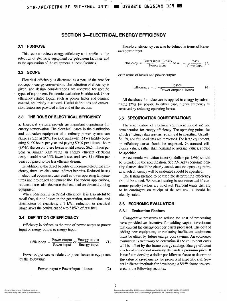
3.1 PURPOSE
This section reviews energy efficiency as it applies to the selection of electrical equipment for petroleum facilities and to the application of the equipment in those facilities.
3.2 SCOPE
Electrical efficiency is discussed as a part of the broader concept of energy conservation. The definition of efficiency is given, and design considerations are reviewed for specific
. types of equipment. Economic evaluation is addressed. Other efficiency related topics, such as power factor and demand control, are briefly discussed. Useful definitions and conver- sion factors are provided at the end of the section.
3.3 THE ROLE OF ELECTRICAL EFFICIENCY
a. Electrical systems provide an important opportunity for energy conservation. The electrical losses in the distribution and utilization equipment of a refinery power system can range as high as 20%. For a 60 megawatt (MW) facility oper- ating 8,000 hours per year and paying $0.07 per kilowatt-hour (kWh), the cost of these losses would exceed $6.5 million per year. -A similar plant using an energy efficient electrical design could have 1.5% fewer losses and save $1 million per year compared to the less efficient design.
In addition to the direct benefits of increased electrical effi- ciency, there are also some indirect benefits. Reduced losses in electrical equipment can result in lower operating tempera- tures and prolonged equipment life. For indoor applications, reduced losses also decrease the heat load on air conditioning equipment.
When considering electrical efficiency, it is also useful to recall that, due to losses in the generation, transmission, and distribution of electricity, a 1 kWh reduction in electrical usage saves the equivalent of 4 to 5 kWh of raw fuel.
3.4 DEFINITION OF EFFICIENCY
Efficiency is defined as the ratio of power output to power input or energy output to energy input:
Efficiency = Power output Energy output Power input Energy input or (1)
Power output can be related to power losses in equipment by the following:
Power output = Power input - losses (2)
Therefore, efficiency can also be defined in terms of losses and power input
Efficiency = Power input - losses losses o r = 1 - Power input Power input (3)
or in terms of losses and power output:
Efficiency = 1 - losses Power output + losses (4)
All the above formulae can be applied to energy by substi- tuting kWh for power. In either case, higher efficiency is achieved by reducing operating losses.
3.5 SPECIFICATION CONSIDERATIONS
The specification of electrical equipment should include consideration for energy efficiency. The operating points for which efficiency data are desired should be specified. Usually 'h, 1/4, and full load data are requested. For large equipment, an efficiency curve should be requested. Guaranteed effi- ciency values, rather than nominal or average values, should be specified.
An economic evaluation factor (in dollars per kwh) should be included in the specification. See 3.6. Any economic pen- alty clauses should be clearly stated, and the operating point at which efficiency will be evaluated should be specified.
The testing method to be used for determining efficiency should be stated. Witnessed testing is recommended if eco- nomic penalty factors are involved. Payment terms that are to be contingent on receipt of the test results should be clearly stated.
3.6 ECONOMIC EVALUATION
3.6.1 Evaluation Factors
Competitive pressures to reduce the cost of processing have provided an incentive for adding capital investment that can cut the energy cost per barrel processed. The cost of adding new equipment, or replacing inefficient equipment must be offset by future energy cost savings. An economic evaluation is necessary to determine if the equipment costs will be offset by the future energy savings. Energy efficient electrical equipment normally demands a premium price. It is useful to develop a dollar-per-kilowatt factor to determine the value of saved energy for projects at a specific site. Sev- eral different methods for developing a $/kW factor are cov- ered in the following sections.
9
Copyright American Petroleum Institute Reproduced by IHS under license with API
Document provided by IHS Licensee=BG Group/5943895100, 01/31/2005 04:58:30 MSTQuestions or comments about this message: please call the Document Policy Groupat 303-397-2295.
--`,`,,,`,`,`,,,```,,``,,`,``,,-`-`,,`,,`,`,,`---
10 API RECOMMENDED PRACTICE 540
3.6.2 Simple Payback h = hours of operation per year,
The least complex dollar-per-kilowatt factor is based on N = number of years in evaluation period, simple payback, which does not account for the dèpreciated value of future savings:
T = income tax rate paid by the user,
i = effective interest rate $ k W = ChN (1 - T ) ( 5 )
- - 1 = - - . 1+R, 1 +R,
1 (81, where
$1 kW = profit to the user for reducing power usage by R1 = anticipated annual escalation rate for cost of 1 kW, electricity,
C = cost of electricity, in dollars per kwh, R2 = desired annual rate of return on investment. '
h = hours of operation per year, N = number of years in evaluation period, Using the example,of equation 5 along with a 15% rate of T = income tax rate paid by the user. return and an 8% power cost escalation rate, the dollar-per-
kilowatt evaluation factor would be calculated as follows: The use of the factor is demonstrated in the following
example. Assume a piece of electrical equipment operates 1 ' =-- 1 = 0.0648 continuouszy at a location where the cost of electricity is $O.OSkWh, and the desired payback period is 5 years. Income is taxed at a 40% rate. The factor would be calculated C
1 + 0.08 (9)
as follows: $ / k W = ( I - 0 . 4 0 ) ~ 1 + O.064SJ - 1
0.0648 (1 + 0.0648) 5 (10)
$/kW=- $005x8760hx5yrx(l-0.40) - = $1,314/kW (6) kWh yr
= $1,093 I kW This factor is the expected cost for continuously operat-
ing a load of one kW for 5 years. This cost factor is then This equation is a useful way to include the time value of compared to the ratio of the price premium for high effi- money, and is suitable for most economic evaluations of ciency equipment divided by the loss reduction. If the ratio energy efficiency improvements. For very large projects it may is less than $1,314, then it pays to spend the money for the be desirable to use an evaluation method which further refines high efficiency equipment. For example, if an energy effi- the preceding equations to allow for such factors as deprecia- cient transformer costs $4,000 more than a standard trans- tion, tax investment credits, and variable escalation rates. former, and it reduces the losses by 5 kW, the incremental cost is ($4,00015 kW) or $SOOkW. The energy efficient unit 3.7 COGENERATION AND ENERGY RECOVERY should, therefore, be selected.
3.6.3 Time Value of Money
Power costs can be reduced by investing in-plant genera- tion. The generation normally is added in the form of cogen- eration. Cogeneration means using the waste heat from a
Equation 5 does not take into account the time value of power generating cycle for process heating; or conversely, money. Future savings should be adjusted for increases in using waste heat from a plant process to generate power. power costs and the required cost of capital. The following The generation cycle thermal efficiency thus can be equation provides a dollar-per-kilowatt factor that allows for increased from about 25% (typical industrial generating power cost inflation and desired rate of return on investment. efficiency) to about 70% when waste heat is recovered.
Power generated in the cogenerating mode is normally less expensive than purchased power and results in direct sav-
(7) ings to the plant. Typical utility generating units operate at 35% efficiency, so the higher efficiency of cogenerating can make it an attractive option.
where One of two power cycles are used for cogenerating, depending on the plant processes used to absorb the waste heat. The Brayton cycle includes a gas turbine to generate power, and a waste heat boiler to generate steam from the hot
C = cost of electricity, in dollars per kwh, 500°C to 600°C (= 950°F to 1100°F) exhaust gases. In some
$IkW=Ch(l-T) l + i N - 1 i(1 +i>*
$1 kW = profit to the user of reducing power usage by 1 kW,
Copyright American Petroleum Institute Reproduced by IHS under license with API
Document provided by IHS Licensee=BG Group/5943895100, 01/31/2005 04:58:30 MSTQuestions or comments about this message: please call the Document Policy Groupat 303-397-2295.
--`,`,,,`,`,`,,,```,,``,,`,``,,-`-`,,`,,`,`,,`---
(STD*API/PETRO RP 540-ENGL 1999 R 0732270 Ob35550 T O T H
ELECTRICAL INSTALLATIONS IN PETROLEUM PROCESSING PLANTS 11
Fuel Electric power
Heat recovery steam generator
f f
c """"
I Gas turbine I heat I
Process I
I
Condensate treating
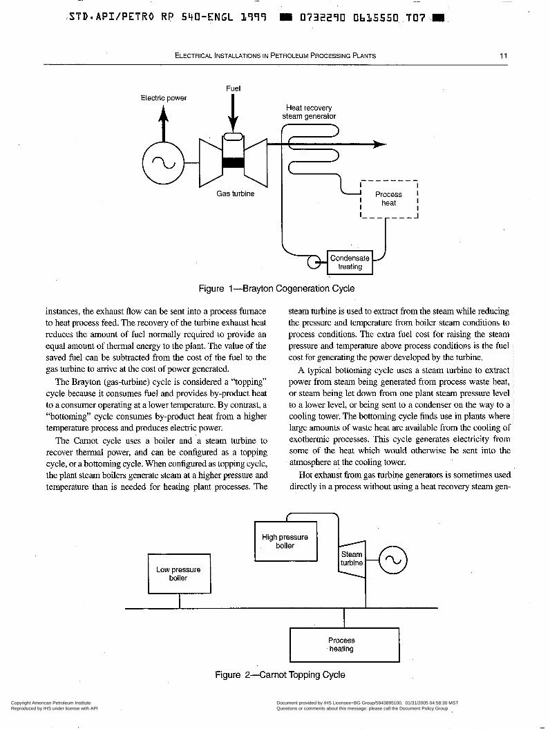
Figure 1 "Brayton Cogeneration Cycle
instances, the exhaust flow can be sent into a process furnace to heat process feed. The recovely of the turbine exhaust heat reduces the amount of fuel normally required to provide an equal amount of thermal energy to the plant. The value of the saved fuel can be subtracted from the cost of the fuel to the gas turbine to arrive at the cost of power generated.
The Brayton (gas-turbine) cycle is considered a "topping" cycle because it consumes fuel and provides by-product heat to a consumer operating at a lower temperature. By contrast, a "bottoming" cycle consumes by-product heat from a higher temperature process and produces electric power.
The Carnot cycle uses a boiler and a steam turbine to recover thermal power, and can be configured as a topping cycle, or a bottoming cycle. When configured as topping cycle, the plant steam boilers generate steam at a higher pressure and temperature than is needed for heating plant processes. The
steam turbine is used to extract from the steam while reducing the pressure and temperature from boiler steam conditions to process conditions. The extra fuel cost for raising the steam pressure and temperature above process conditions is the fuel cost for generating the power developed by the turbine.
A typical bottoming cycle uses a steam turbine to extract power from steam being generated from process waste heat, or steam being let down from one plant steam pressure level to a lower level, or being sent to a condenser on the way to a cooling tower. The bottoming cycle finds use in plants, where large amounts of waste heat are available from the cooling of exothermic processes. This cycle generates electricity from some of the heat which would othelwise be sent into the atmosphere at the cooling tower.
Hot exhaust from gas turbine generators is sometimes used directly in a process without using a heat recovery steam gen-
I Low pressure boiler I
c 3
High pressure boiler
Process heating
Figure 2-Carnot Topping Cycle
Copyright American Petroleum Institute Reproduced by IHS under license with API
Document provided by IHS Licensee=BG Group/5943895100, 01/31/2005 04:58:30 MSTQuestions or comments about this message: please call the Document Policy Groupat 303-397-2295.
--`,`,,,`,`,`,,,```,,``,,`,``,,-`-`,,`,,`,`,,`---
I 12 API RECOMMENDED PRACTICE 540
erator. Three examples of direct heating with turbine exhaust are: reducing the viscosity of products in transport pipelines; heating process feeds to process units; and supplying thermal energy for absorption refrigeration cycles.
Heating viscous products will lower viscosity and reduce the pumping energy required to transport the products through pipelines. Fired heaters are normally used for this. When gas turbines are sometimes used as generator drives to provide power for the transport pump motors, or are used to drive the pumps directly, the exhaust can be passed through an exchanger to heat the product, instead of using a fired heater. Using the waste heat from the gas turbine's exhaust will save the cost of the fuel used for a fired heater.
In process plants, gas turbine exhaust is used to heat feed stocks to processes, or to preheat combustion air for the pro- cess furnaces. This displaces much of the fuel that would oth- erwise be consumed.
The absorption refrigeration cycle uses a heat source to change the state of a refrigerant. The hot exhaust from a gas- turbine generator can be used with an absorption cycle to pro- vide cooling. Absorption cycle equipment manufacturers can provide pre-engineered system elements to match the exhaust flow conditions of a number of gas turbines.
Sometimes there are opportunities to recover energy from process or utility streams. One method of energy recovery is the power recovery turbine, which is often used on catalytic cracking units to recover energy from the regenerator flue gases. The flue gases are directed through an expander which drives the unit's air blower, and an electric generator. The out- put of the generator is usually in the range of 5 megawatts to 10 megawatts {MW). Typically, an induction generator is used for this service.
A high-pressure fuel gas feed to a petroleum facility can also be used as a source of electric power by dropping the line pressure to plant utility pressure through an expander instead of a let-down valve. The expander is used to drive an induc- tion generator adding power to the electric system. The majority of the gas flow goes through the expander, while a pressure control flow goes through a parallel control valve.
3.8 DESIGN CONSIDERATIONS
3.8.1 Transformers
Transformer efficiencies vary, depending on transformer characteristics. High-efficiency units can be purchased that provide efficiencies in excess of 99%. The importance of transformer efficiencies is that all power received from utili- ties (and 'much, if not all, received from in-plant generation) is transformed one or more times to reach utilization voltage levels; thus, the 1 or 2% losses occurring in transformers are applied to large blocks of power.
Transformer losses consist of no-load losses and load losses. No-load losses are losses resulting from energizing the primary winding at rated voltage with the secondary winding
open-circuited. These losses include eddy current losses, hys- teresis losses, dielectric losses, and losses due to the resis- tance of the primary winding to excitation current. The eddy current and hysteresis losses are the most significant compo- nent of no-load losses. Because these losses occur in the core of the transformer, no-load losses are sometimes referred to as core losses or iron losses. For a given voltage, no-load losses can be considered to be constant.
Load losses vary with the flow of load current and include 12R losses, eddy current losses, and stray load losses. The 12R losses are the most significant and are caused by the flow of load current in both primary and seconday windings. Higher efficiency transformers usually have copper windings to min- imize 12R losses. Where forced cooling is specified, addi- tional energy is consumed by fans or oil circulating pumps.
While transformers should be sized on the basis of maxi- mum load, they should be designed for maximum efficiency at nolmal operating load, and efficiency should be evaluated accordingly. When specifying transformers, the load at which efficiency will be evaluated should be given.
3.8.2 Motors and Generators
Motor loads are the major consumers of energy in process plants. Typically, they can account for 70% of the electrical energy consumption. Motor efficiencies vary from 65% for the smallest HP motors, to 98% for the largest motors. High efficiency designs are available for motors in the standard frame size range. In the United States, the 1992 Energy Pol- icy Act requires energy efficient motors for most motor cate- gories.
Motor losses consist of the following:
a. Stator 12R loss. b. Rotor 12R loss. c. Core loss (hysteresis and eddy current). d. Friction and windage. e. Stray-load loss. f. Excitation equipment losses (for synchronous machines).
Manufacturing design parameters that affect motor losses include:
a. Quality and thickness of lamination steel. . b. Size of the air gap. c. Stator and rotor resistances. d. Slot configurations. e. Number of poles (lower design speeds result in lower efficiencies).
Much effort is made to optimize these parameters because they also affect motor power factor, inrush current, and start- ing torque.
Operating conditions also affect motor efficiency. Typi- cally, motor efficiency falls off rapidly as motor load is decreased below one-half of rated load. Operating a motor at
Copyright American Petroleum Institute Reproduced by IHS under license with API
Document provided by IHS Licensee=BG Group/5943895100, 01/31/2005 04:58:30 MSTQuestions or comments about this message: please call the Document Policy Groupat 303-397-2295.
--`,`,,,`,`,`,,,```,,``,,`,``,,-`-`,,`,,`,`,,`---
ELECTRICAL INSTALLATIONS IN PETROLEUM PROCESSING PLANTS 13
less than rated voltage will cause a decrease in efficiency due to higher stator losses and rotor losses. Operating at overvolt- age decreases efficiency because higher magnetizing current and saturation cause increased stator and core losses. Operat- ing with unbalanced voltages will increase losses (due to neg- ative sequence torque) and result in higher winding temperatures. Motors connected to variable speed drives experience higher losses because of the harmonic content of the supply voltage and the load current. This is due to higher than normal hysteresis and eddy currents induced in the stator and rotor steel by the harmonic currents.
3.8.3 Lighting Equipment
Although lighting does not represent a major percentage of the electlical energy consumption of a petroleum facility, it nonetheless provides another area where energy savings can be achieved. The following guidelines can result in an energy efficient lighting system:
a. Use the highest efficacy [lumens per watt (lmnV)] lamp that is capable of directing light to the task area involved. b. Select efficient ballasts (e.g., electronic ballasts for fluo- rescent fixtures). c. Maximize use of floodlights to illuminate general process areas. d. Use photocell or time controls to turn off outdoor lighting during daylight hours. e. Use manual controls for tower lighting with controls located at the tower base. f. Monitor lighting levels and reduce them where appropri- ate. For building lighting, this produces additional energy savings because of the reduced load on air conditioning equipment. g. Keep lamps and reflectors clean to obtain maximum light output.
3.8.4 Adjustable Speed Motor Control
-
Centrifugal pumps, fans, and compressors constitute a large percentage of the motor-driven loads in a petroleum facility. The torque requirements of these centrifugal loads vary as the square of the speed; thus, the brake horsepower required varies as the cube of the speed.
Traditionally, centrifugal loads have been designed to oper- ate at constant speed with the process flow being controlled by some type of throttling means (pump control valves, fan dampers, or compressor inlet guide vanes). The energy losses from throttling can be substantial.
As an alternative to throttling, the speed of the centrifu- gal load can be controlled to obtain the desired flow rate without producing excessive pressure. Because the flow rate varies directly with speed while the horsepower requirement varies as the cube of the speed, using speed reduction to lower flow rates will result in a significant
horsepower reduction. For example, reducing the flow to one-half its initial value by lowering the speed of the load will cause the brake horsepower of the load to be reduced to one-eighth of its initial value.
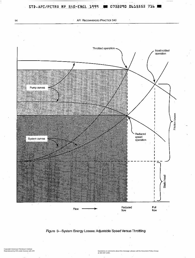
A typical pump head-flow curve is depicted in Figure 3 to further illustrate the attractiveness of using speed adjustment to control flow rate. The darker-shaded area to the lower left of each operating point indicates the power required for that operating point. The lighter-shaded afëa indicates the power savings that result from using speed reduction rather than throttling to control flow rate. In general, a steep system curve, or a steep pump curve, will accentuate the potential power savings. Also, the lower the static head involved, the greater the power savings will be as a percentage of overall power consumption.
The conventional methods for achieving speed adjustment include hydraulic couplings, adjustable sheave belt systems, eddy current clutches, and wound-rotor motors. These devices are relatively inefficient, however, and usually require frequent maintenance. DC motors allow speed adjustment with improved efficiency but are also prone to requiring fre- quent maintenance and are difficult to apply in classified areas. Electronic adjustable-frequency controllers also pro- vide speed adjustment and have been improved over the last decade. They are now the method of choice when adjustable speed drives are needed. The maintenance level for these con- trollers is the lowest of the alternative methods, however, these drives create voltage aild current harmonics which may require remedial modifications to the power system and drive motor. Adjustable-frequency controllers have relatively high efficiencies and can be used with induction motors whch require low maintenance and are readily available for classi- fied areas. (See also Section 2.)
The capital cost of adjustable-speed drive equipment is higher than for constant speed equipment, so an economic evaluation as outlined in 3.6 is required to determine if the potential energy savings offsets the increased cost. A major factor in such an evaluation will be the duty cycle of the equipment involved; i.e., the percentage of time that equip- ment will function at operating points requiring less horse- power than the design point. If the equipment is expected to operate at close to its design point for a high percentage of time, then using an adjustable-speed drive system is probably not warranted. It is also important to remember that the appli- cation of adjustable-speed drives requires the consideration of other design factors, such as avoiding the operation of .equip- ment at critical speeds and evaluating the effects of system harmonics that may be generated by adjustable frequency drive equipment. (See also 6.10.4.)
3.8.5 Conductor Sizing
Power cables are another some of energy loss in an electri- cal system. The magnitude of the energy loss depends on the
Copyright American Petroleum Institute Reproduced by IHS under license with API
Document provided by IHS Licensee=BG Group/5943895100, 01/31/2005 04:58:30 MSTQuestions or comments about this message: please call the Document Policy Groupat 303-397-2295.
--`,`,,,`,`,`,,,```,,``,,`,``,,-`-`,,`,,`,`,,`---
14 API RECOMMENDED PRACTICE 540
Throttled operation
I l f Nonthrottled operation
\
J.
Flow ____f Reduced flow
Full flow
Figure +System Energy Losses: Adjustable Speed Versus Throttling
Copyright American Petroleum Institute Reproduced by IHS under license with API
Document provided by IHS Licensee=BG Group/5943895100, 01/31/2005 04:58:30 MSTQuestions or comments about this message: please call the Document Policy Groupat 303-397-2295.
--`,`,,,`,`,`,,,```,,``,,`,``,,-`-`,,`,,`,`,,`---
~ ~~
STD-APIIPETRO RP 540-ENGL 1999 I 0732290 Ob15554 652 pI
ELECTRICAL INSTALLATIONS IN PETROLEUM PROCESSING PLANTS 15
resistance of the cable as well as the amount of current expected to flow in the circuit. After power cables have been sized to meet the governing criteria (voltage drop, spare capac- ity, and the requirements of NFPA 70), a check should be made to determine if the anticipated energy loss in the cable would justify purchasing and installing the next larger size cable.
3.9 RELATIONSHIP TO POWER FACTOR
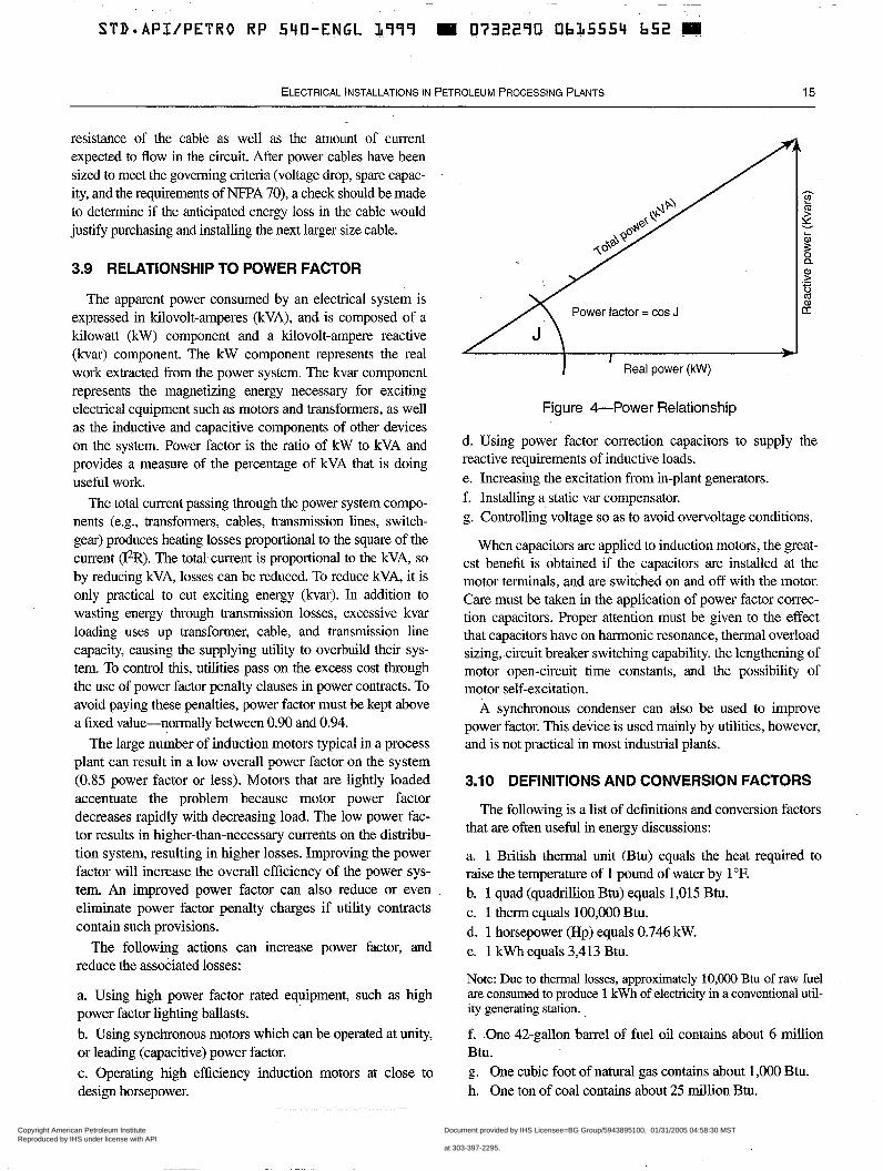
The apparent power consumed by an electrical system is expressed in kilovolt-amperes (kVA), and is composed of a kilowatt (kW) component and a kilovolt-ampere reactive (kvar) component. The kW component represents the real work extracted from the power system. The kvar component represents the magnetizing energy necessary for exciting electrical equipment such as motors and transformers, as well as the inductive and capacitive components of other devices on the system. Power factor is the ratio of kW to kVA and provides a measure of the percentage of kVA that is doing useful work.
The total current passing through the power system compo- nents (e.g., transformers, cables, transmission lines, switch- gear) produces heating losses proportional to the square of the current (12R). The total current is proportional to the kVA, so by reducing kVA, losses can be reduced. To reduce kVA, it is only practical to cut exciting energy (kvar). In addition to wasting energy through transmission losses, excessive kvar loading uses up transformer, cable, and transmission line capacity, causing the supplying utility to overbuild their sys- tem. To control this, utilities pass on the excess cost through the use of power factor penalty clauses in power contracts. To avoid paying these penalties, power factor must be kept above a fixed value-normally between 0.90 and 0.94.
The large number of induction motors typical in a process plant can result in a low overall power factor on the system (0.85 power factor or less). Motors that are lightly loaded accentuate the problem because motor power factor decreases rapidly with decreasing load. The low power fac- tor results in higher-than-necessary currents on the distribu- tion system, resulting in higher losses. Improving the power factor will increase the overall efficiency of the power sys- tem. An improved power factor can also reduce or even eliminate power factor penalty charges if utility contracts contain such provisions.
The following actions can increase power factor, and reduce the associated losses:
a. Using high power factor rated equipment, such as high power factor lighting ballasts. b. Using synchronous motors which can be operated at unity, or leading (capacitive) power factor. c. Operating high efficiency induction motors at close to design horsepower.
Figure &Power Relationship
d. Using power factor correction capacitors to supply the reactive requirements of inductive loads. e. Increasing the excitation from in-plant generators. f. Installing a static var compensator. g. Controlling voltage so as to avoid overvoltage conditions.
When capacitors are applied to induction motors, the great- est benefit is obtained if the capacitors are installed at the motor terminals, and are switched on and off with the motor. Care must be taken in the application of power factor correc- tion capacitors. Proper attention must be given to the effect that capacitors have on harmonic resonance, thermal overload sizing, circuit breaker switching capability, the lengthening of motor open-circuit time constants, and the possibility of motor self-excitation.
A synchronous condenser can also be used to improve power factor. This device is used mainly by utilities, however, and is not practical in most industrial plants.
3.10 DEFINITIONS AND CONVERSION FACTORS
The following is a list of definitions and conversion factors that are often useful in energy discussions:
a. 1 British thermal unit (Btu) equals the heat required to raise the temperature. of 1 pound of water by 1 OF. b. 1 quad (quadrillion Btu) equals 1,015 Btu. c. 1 therm equals 100,000 Btu. d. 1 horsepower (HP) equals 0.746 kW. e. 1 kWh equals 3,413 Btu.
Note: Due to thermal losses, approximately 10,000 Btu of raw fuel are consumed to produce 1 kWh of electricity in a conventional util- ity generating station.
f. One 42-gallon barrel of fuel oil contains about 6 million Btu. g. One cubic foot of natural gas contains about 1,000 Btu. h. One ton of coal contains about 25 million Btu.
Copyright American Petroleum Institute Reproduced by IHS under license with API
Document provided by IHS Licensee=BG Group/5943895100, 01/31/2005 04:58:30 MSTQuestions or comments about this message: please call the Document Policy Groupat 303-397-2295.
--`,`,,,`,`,`,,,```,,``,,`,``,,-`-`,,`,,`,`,,`---
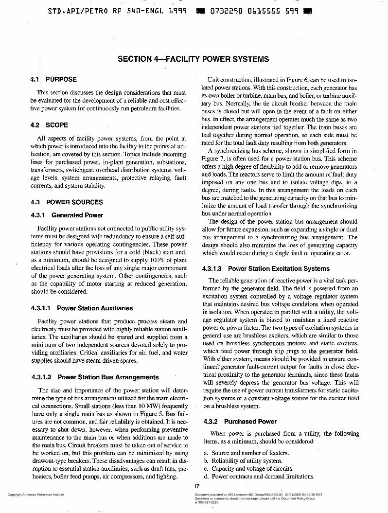
~ ~ ~
STD-API/PETRO RP 54O-ENGL 1999 W 0732290 Ob15555 599 S
SECTION &FACILITY POWER SYSTEMS
4.1 PURPOSE
This section discusses the design considerations that must be evaluated for the development of a reliable and cost effec- tive power system for continuously run petroleum facilities.
4.2 SCOPE
All aspects of facility power systems, from the point at which power is introduced into the facility to the points of uti- lization, are covered by this section. Topics include incoming lines for purchased power, in-plant generation, substations, transformers, switchgear, overhead distribution systems, volt- age levels, system arrangements, protective relaying, fault currents, and system stability.
4.3 POWER SOURCES
4.3.1 Generated Power
Facility power stations not connected to public utility sys- tems must be designed with redundancy to ensure a self-suf- ficiency for various operating contingencies. These power stations should have provisions for a cold (black) start and, as a minimum, should be designed to supply 100% of plant electrical loads after the loss of any single major component of the power generating system. Other contingencies, such as the capability of motor starting at reduced generation, should be considered.
4.3.1.1 Power Station Auxiliaries
Facility power stations that produce process steam and electricity must be provided with highly reliable station auxil- iaries. The auxiliaries should be spared and supplied from a minimum of two independent sources devoted solely to pro- viding auxiliaries. Critical auxiliaries for air, fuel, and water supplies should have steam-driven spares.
4.3.1.2 Power Station Bus Arrangements
The size and importance of the power station will deter- mine the type of bus arrangement utilized for the main electri- cal connections. Small stations (less than 10 MW) frequently have only a single main bus as shown in Figure 5. Bus fail- ures are not common, and fair reliability is obtained. It is nec- essary to shut down, however, when performing preventive maintenance to the main bus or when additions are made to the main bus. Circuit breakers must be taken out of service to be worked on, but this problem can be minimized by using drawout-type breakers. These disadvantages can result in dis- ruption to essential station auxiliaries, such as draft fans, pre- heaters, boiler feed pumps, air compressors, and lighting.
Unit construction, illustrated in Figure 6, can be used in iso- lated power stations. With this construction, each generator has its own boiler or turbine, main bus, and boiler, or turbine auxil- iary bus. Normally, the tie circuit breaker between the main buses is closed but wili open in the event of a fault on either bus. In effect, the arrangement operates much the same as two independent power stations tied together. The main buses are tied together during normal operation, so each side must be rated for the total fault duty resulting from both generators.
A synchronizing bus scheme, shown in simplified form in Figure 7, is often used for a power station bus. This scheme offers a high degree of flexibility to add or remove generators and loads. The reactors serve to limit the amount of fault duty imposed on any one bus and to isolate voltage dips, to a degree, during faults. In this arrangement the loads on each bus are matched to the generating capacity on that bus to min- imize the amount of load transfer through the synchronizing bus under normal operation.
The design of the power station bus arrangement should allow for future expansion, such as expanding a single or dual bus arrangement to a synchronizing bus arrangement. The design should also minimize the loss of generating capacity which would occur during a single fault or operating error.
4.3.1.3 Power Station Excitation Systems
The reliable generation of reactive power is a vital task per- formed by the generator field. The field is powered from an excitation system controlled by a voltage regulator system that maintains desired bus voltage conditions when operated .in isolation. When operated in parallel with a utility, the volt- age regulator system is biased to maintain a fixed reactive power or power factor. The two types of excitation systems in general use are brushless exciters, which are similar to those used on brushless synchronous motors; and static exciters, which feed power through slip rings to the generator field. With either system, means should be provided to ensure con- tinued- generator fault-current output for faults in close elec- trical proximity to the generator terminals, since these faults will severely depress the generator bus voltage. This will require the use of power current transformers for static excita- tion systems or a constant voltage source for the exciter field on a brushless system.
4.3.2 Purchased Power
When power is purchased from a utility, the following items, as a minimum, should be considered:
a. Source and number of feeders. b. Reliability of utility system. c. Capacity and voltage of circuits. d. Power contracts and demand limitations.
17
Copyright American Petroleum Institute Reproduced by IHS under license with API
Document provided by IHS Licensee=BG Group/5943895100, 01/31/2005 04:58:30 MSTQuestions or comments about this message: please call the Document Policy Groupat 303-397-2295.
--`,`,,,`,`,`,,,```,,``,,`,``,,-`-`,,`,,`,`,,`---
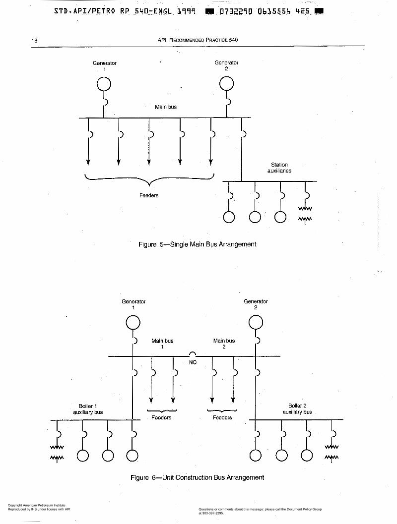
18 API RECOMMENDED PRACTICE 540
Generator 1
Generator 2
Q > Q > Main bus
i i .,i i 1 >
Station auxiliaries
\ J
Feeders
Figure 5-Single Main Bus Arrangement
Generator 1
Generator 2
Q Main bus
2
Boiler 1 Boiler 2
Feeders Feeders auxiliary bus - - auxiliary bus
Figure 6-Unit Construction Bus Arrangement
Copyright American Petroleum Institute Reproduced by IHS under license with API
Document provided by IHS Licensee=BG Group/5943895100, 01/31/2005 04:58:30 MSTQuestions or comments about this message: please call the Document Policy Groupat 303-397-2295.
--`,`,,,`,`,`,,,```,,``,,`,``,,-`-`,,`,,`,`,,`---
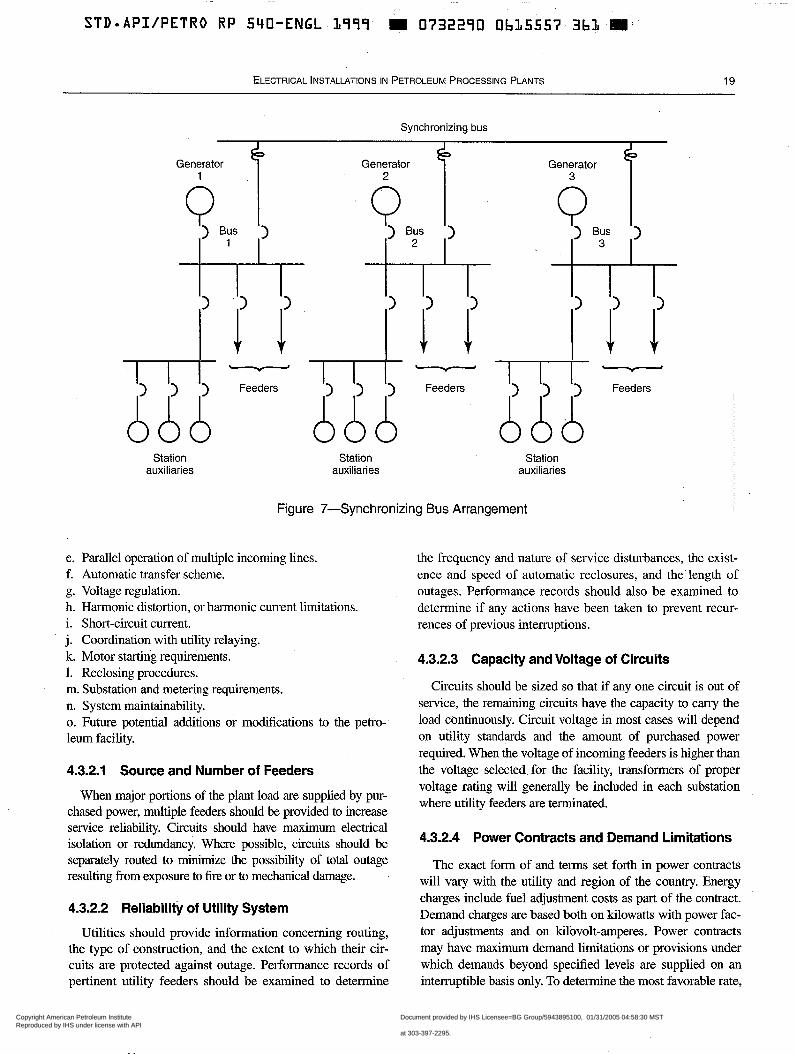
STD*API/PETRO RP 540-ENGL B999 W 0732290 0615557 3bB ai
ELECTRICAL INSTALLATIONS IN PETROLEUM PROCESSING PLANTS 19
Synchronizing bus
Generator 3 1
Generator Generator
Q , i ,
) Bus Q ) Bus
I) 7 ; 1) I 2 , 1) I , I 3, I) , Y.1' I 'r 1'
l7-l" 6 6 6 Feeders ~ - - - A ) ) A ) Feeders l-ll" 6 6 6 Feeders
Station Station Station auxiliaries auxiliaries auxiliaries
Figure 7-Synchronizing Bus Arrangement
e. Parallel operation of multiple incoming lines. f. Automatic transfer scheme. g. Voltage regulation. h. Harmonic distortion, or harmonic current limitations. i. Short-circuit current. j. Coordination with utility relaying. k. Motor starting requirements. 1. Reclosing procedures. m. Substation and metering requirements. n. System maintainability. o. Future potential additions or modifications to the petro- leum facility.
4.3.2.1 Source and Number of Feeders
the frequency and nature of service disturbances, the exist- ence and speed of automatic reclosures, and the' length of outages. Performance records should also be examined to determine if any actions have been taken to prevent recur- rences of previous interruptions.
4.3.2.3 Capacity and Voltage of Circuits
Circuits should be sized so that if any one circuit is out of service, the remaining circuits have the capacity to carry the load continuously. Circuit voltage in most cases will depend on utility standards and the amount of purchased power required. When the voltage of incoming feeders is higher than the voltage selected for the facility, transfomers of proper
When major portions of the plant load are supplied by pur- chased power, multiple feeders should be provided to increase
voltage rating will generally be included in each substation where utility feeders are terminated.
service reliability. Circuits should have maximum electrical isolation or redundancy. Where possible, circuits should be separately routed to minimize the possibility of total outage resulting from exposure to fire or to mechanical damage.
4.3.2.2 Reliability of Utility System
Utilities should provide information concerning routing, the type of construction, and the extent to which their cir- cuits are protected against outage. Performance records of pertinent utility feeders should be examined to determine
4.3.2.4 Power Contracts and Demand Limitations
The exact form of and terms set forth in power contracts will vary with the utility and region of the country. Energy charges include fuel adjustment costs as part of the contract. Demand charges are based both on kilowatts with power fac- tor adjustments and on kilovolt-amperes. Power contracts may have maximum demand limitations or provisions under which demands beyond specified levels are supplied on an interruptible basis only. To determine the most favorable rate,
Copyright American Petroleum Institute Reproduced by IHS under license with API
Document provided by IHS Licensee=BG Group/5943895100, 01/31/2005 04:58:30 MSTQuestions or comments about this message: please call the Document Policy Groupat 303-397-2295.
--`,`,,,`,`,`,,,```,,``,,`,``,,-`-`,,`,,`,`,,`---
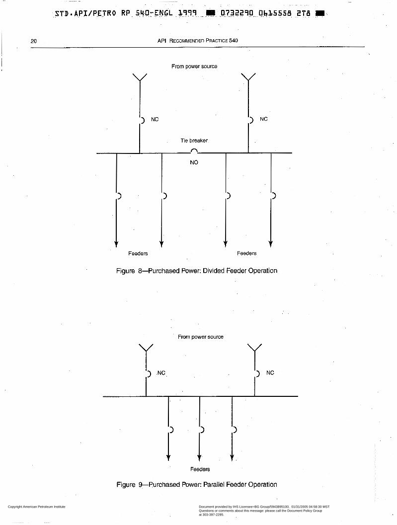
20 API RECOMMENDED PRACTICE 540
From power source
Feeders Feeders
Figure 8-Purchased Power: Divided Feeder Operation
From power source
Feeders
Figure %Purchased Power: Parallel Feeder Operation
Copyright American Petroleum Institute Reproduced by IHS under license with API
Document provided by IHS Licensee=BG Group/5943895100, 01/31/2005 04:58:30 MSTQuestions or comments about this message: please call the Document Policy Groupat 303-397-2295.
--`,`,,,`,`,`,,,```,,``,,`,``,,-`-`,,`,,`,`,,`---
STD-API/PETRO RP 540-ENGL L999 m 0732290 Ob15559 L 3 4 . M
ELECTRICAL INSTALLATIONS IN PETROLEUM PROCESSING PLANTS 21
it is essential to know firm demand and energy requirements as well as daily and seasonal load profiles.
4.3.2.5 Parallel Operation of Incoming Lines
The preferred operation of incoming utility lines is to par- allel them on the substation bus. Typical arrangements are shown in Figures 8 and 9. Suitable relaying must be provided for proper system protection, and, before the feeders can be operated in parallel, protection must be provided (e.g., through the use of synchronization check relays) to verify that the voltages of the feeders are equal and synchronized.
4.3.2.6 Automatic Transfer Scheme
When incoming circuits cannot be paralleled, automatic transfer between the circuits should be considered. Load requirements should be checked carefully, and a regular test- ing method for the automatic transfer scheme should be included. Fast transfer schemes must consider the effects of residual voltage on motors and driven loads.
4.3.2.7 Voltage Regulation
Where utility or plant voltage varies (to unacceptable levels), automatic load-tap-changing transfomers or other methods should be considered for maintaining close voltage regulation.
4.3.2.8 Harmonic Distortion, or Harmonic Current Limitations
Harmonic distortion, typically generated by nonsinusoidal waveforms originating from SCR rectifiers, adjustable speed drives, and similar electronic voltage and frequency con- trolled devices, can cause serious problems in electrical sys- tems. Problems can include overloading and overheating of phase and neutral power systems; problems associated with high electrical noise on the system; inability of electronic hardware to synchronize; failure of frequency-sensitive cir- cuits such as lighting ballasts; failure of adjustable speed drives and motor windings due to reflected waves; and many other abnormalities. IEEE Std 399 and Std 519 should be reviewed for systems with appreciable nonsinusoidal har- monics. Often, utilities will impose limitations on the maxi- mum amount of harmonic current being generated by the customer into the utility supply.
4.3.2.9 Short-Circuit Current
The electrical system must be designed to accommodate the maximum short-circuit current that would result from the combined effect of both utility and in-plant sources. All sys- tem components, such as circuit breakers, transformers, and buses, must have ratings that can adequately withstand and interrupt the effects of the fault currents to which they are exposed. The minimum utility short-circuit level must also be
known so that its effect on motor starting and protective relay settings can be determined.
4.3.2.1 O Coordination with Utility Relaying
Proper coordination between substation and utility protec- tive relaying is essential to minimize the number and duration of power outages. The proper relaying should be selected by the user in collaboration with the utility company.
4.3.2.1 1 Motor Starting Requirements
The voltage drop which occurs on the plant bus during motor starting should be calculated to ensure that plant and utility company limitations are met. The voltage-drop calcu- lation should .be based on the starting of the plant’s largest motor with all other required plant loads in operation. Reduced-voltage starting or an auxiliary starting driver may be required when the utility system is not stiff enough to allow full-voltage starting.
4.3.2.12 Reclosing Procedures
Utilities may employ automatic reclosing schemes on overhead lines because the faults which occur on overhead lines are often transient in nature. The delay time and number of automatic reclosures are based on a review of such factors as the voltage level of the feeder and the feeding of the plant from either a radial distribution feeder or a tap on a transmis- sion tie line. The delay time before and between automatic reclosures and the number of reclosures are required for the design of protective relaying and system control schemes.
4.3.2.13 Substation and Metering Requirements
Characteristics of a facility substation, should take into consideration:
a. Largest single load. b. Total connected load. c. Maximum allowable voltage drop. d. Utility reliability. e. Substation ownership (utility versus user). f. Primary versus secondary metering. g. Spare transformer capacity. h. Future load growth and expansion requirements. i. Grounding. j. Isoceraunic (lightning frequency) level and protection schemes. k. Facility life. 1. Maintainability as it would affect substation design.
4.3.2.14 System Maintainability
The electrical distribution and utilization system must be designed so that it can be inspected and maintained on a regular basis to assure reliable operation. Often, the maintenance of
Copyright American Petroleum Institute Reproduced by IHS under license with API
Document provided by IHS Licensee=BG Group/5943895100, 01/31/2005 04:58:30 MSTQuestions or comments about this message: please call the Document Policy Groupat 303-397-2295.
--`,`,,,`,`,`,,,```,,``,,`,``,,-`-`,,`,,`,`,,`---
~
STDr-&PI /PETRO RP 540-.ENGL L999 m 07?2290 . .
22 API RECOMMENDED PRACTICE 540
electrical facilities for a petroleum facility are maintained at the same maintenance intervals as other process equipment. The connection of unrelated process equipment should be avoided if it cannot be shutdown during the primary facility shutdown.
4.3.2.15 Facility Additions or Modifications
Design of electrical systems should take into consider- ation any potential additions or modifications of the facility. This is especially important when selecting equipment fault duty ratings and designing provisions for future expansion or additions.
4.3.3 Parallel Operation with Purchased and Generated Power
When a utility supplies a part of the facility power require- ments and operates in parallel with plant generated power, the following must be considered:
a. Division and interchange of real and reactive power. b. Protective relaying. c. Service restoration procedures.
4.3.3.1 Division and Interchange of Real and Reactive Power
Power interchanges between utility and industrial sys- tems can vary due to excess plant power generation, utility power restrictions, or load adjustments to maintain constant demand on the utility system. Contracts for the purchase of utility power should include the amount of kilowatts and kilovars and the division or interchange of them between the utility and the facility. If the utility line voltage is subject to wide variations, a method for controlling kilovar inter- change as well as regulating voltage should be considered. Possible methods include automatic load-tap changers on transformers, power factor correction capacitors, and power factor control of the generator or synchronous motor excita- tion systems.
4.3.3.2 Protective Relaying
Protective relaying must be provided to protect the plant and its generation from faults or power loss in the utility system. The relaying must protect against adverse interac- tions between the systems and, if necessary for system sta- bility, must act to isolate plant generation from the utility system. Impedance, reverse power, directional overcurrent, or underfrequency relays may be used to trip the incoming supply circuit breakers. If plant load exceeds generation, an automatic load-shedding system should be provided r 0
relieve generation overloads after isolation and to maintain plant system stability.
4.3.3.3 Service Restoration Procedures
Various fault or switching conditions may cause facility and utility generating systems to separate. The usual sequence involves a fault transient disturbance affecting both systems until separation occurs, followed by recovery of the isolated systems. The fault transient may cause a voltage dip which will cause motors to drop off the line; however, if pro- cess conditions allow, important drives. can have their control equipped to permit their restarting automatically when plant voltage recovers.
Operation of plant generation after separation may require automatically adjusting the load on plant generation to the load level that it can successfully restart automatically and supply continuously with acceptable voltage and frequency levels. If the plant has been receiving power from the public utility, voltage and frequency will fall unless load-shedding restores the proper balance or the plant turbine-generators can increase output to the proper level. If the plant had been send- ing power to the public utility before isolation, electrical out- put must be reduced. The effect of this reduction on plant steam system conditions must also be determined.
Paralleling of the plant generation and the utility system should be possible only at selected circuit breakers that are equipped with synchronizing switches connecting these breakers into the plant synchronizing system. Other circuit breakers where inadvertent paralleling is possible should be equipped with synchronizing-check relays that prevent clos- ing unless voltage and frequency conditions at both terminals of the breakers are within prescribed limits. Relays which protect the system during fault conditions must be applied and set carefully to prevent separation from occurring during synchronizing swings.
A power system study is normally required to provide the proper protective relaying and settings as well as the generat- ing system and load shedding system parameters necessary for system stability during the fault and recovery transients.
4.4 SYSTEM VOLTAGES
4.4.1 Selection
The selection of system voltages in a facility is based pri- marily on economics, with consideration given to the follow- ing factors:
a. b. C.
d. e. f. g: h. 1.
Class of service available from the utility. Total connected load. Planning for future growth. Plant standardization of equipment. Density and distribution of the load. Safety. Interconnection to existing systems. Equipment availability. Practical conductor and equipment sizes.
Copyright American Petroleum Institute Reproduced by IHS under license with API
Document provided by IHS Licensee=BG Group/5943895100, 01/31/2005 04:58:30 MSTQuestions or comments about this message: please call the Document Policy Groupat 303-397-2295.
--`,`,,,`,`,`,,,```,,``,,`,``,,-`-`,,`,,`,`,,`---
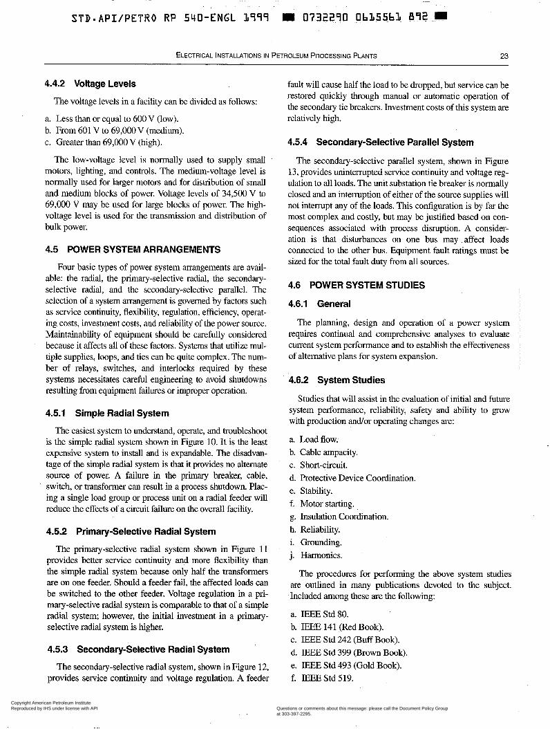
~
STD.API/PETRO RP 540-ENGL L999 111 07322.70 ObL55b4 6 9 2 . . m
ELECTRICAL INSTALLATIONS IN PETROLEUM PROCESSING PLANTS 23
4.4.2 Voltage Levels
The voltage levels in a facility can be divided as follows:
a. Less than or equal to 600 V (low). b. From 601 V to 69,000 V (medium). c. Greater than 69,000 V (high).
The low-voltage level is normally used to supply small motors, lighting, and controls. The medium-voltage level is normally used for larger motors and for distribution of small and medium blocks of power. Voltage levels of 34,500 V to 69,000 V may be used for large blocks of power. The high- voltage level is used for the transmission and distribution of bulk power.
4.5 POWER SYSTEM ARRANGEMENTS
Four basic types of power system arrangements are avail- able: the radial, the primary-selective radial, the secondary- selective radial, and the secondary-selective parallel. The selection of a system arrangement is governed by factors such as service continuity, flexibility, regulation, efficiency, operat- ing costs, investment costs, and reliability of the power source. Maintainability of equipment should be carefully considered because it affects all of these factors. Systems that utilize mul- tiple supplies, loops, and ties can be quite complex. The num- ber of relays, switches, and interlocks required by these systems necessitates careful engineering to avoid shutdowns resulting from equipment failures or improper operation.
4.5.1 Simple Radial System
The easiest system to understand, operate, and troubleshoot is the simple radial system shown in Figure 10. It is the least expensive system to install and is expandable. The disadvan- tage of the simple radial system is that it provides no alternate source of power. A failure in the primary breaker, cable, switch, or transformer can result in a process shutdown. Plac- ing a single load group or process unit on a radial feeder will reduce the effects of a circuit failure on the overall facility.
4.5.2 Primary-Selective Radial System
The primary-selective radial system shown in Figure 11 provides better service continuity and more flexibility than the simple radial system because only half the transformers are on one feeder. Should a feeder fail, the affected loads can be switched to the other feeder. Voltage regulation in a pri- mary-selective radial system is comparable to that of a simple radial system; however, the initial investment in a primary- selective radial system is higher.
4.5.3 Secondary-Selective Radial System
The secondary-selective radial system, shown in Figure 12, provides service continuity and voltage regulation. A feeder
fault will cause half the load to be dropped, but service can be restored quickly through manual or automatic operation of the secondary tie breakers. Investment costs of this system are relatively high.
4.5.4 Secondary-Selective Parallel System
The secondary-selective parallel system, shown in Figure 13, provides uninterrupted service continuity and voltage reg- ulation to all loads. The unit substation tie breaker is normally closed and an intemption of either of the source supplies will not interrupt any of the loads. This configuration is by far the most complex and costly, but may be justified based on con- sequences associated with process disruption. A consider- ation is that disturbances on one bus may affect loads connected to the other bus. Equipment fault ratings must be sized for the total fault duty from all sources.
4.6 POWER SYSTEM STUDIES
4.6.1 General
The planning, design and operation of a power system requires continual and comprehensive analyses to evaluate current system performance and to establish the effectiveness of alternative plans for system expansion.
4.6.2 System Studies
Studies that will assist in the evaluation of initial and future system performance, reliability, safety and ability to grow with production and/or operating changes are:
a. Load flow. b. Cable ampacity. c. Short-circuit. d. Protective Device Coordination. e. Stability. f. Motor starting. g. Insulation Coordination. h. Reliability. i. Grounding. j. Harmonics.
The procedures for performing the above system studies are outlined in many publications devoted to the subject. Included among these are the following:
a. IEEE Std SO. b. IEEE 141 (Red Book). c. IEEE Std 242 (Buff Book). d. IEEE Std 399 (Brown Book). e. IEEE Std 493 (Gold Book). f. IEEE Std 519.
Copyright American Petroleum Institute Reproduced by IHS under license with API
Document provided by IHS Licensee=BG Group/5943895100, 01/31/2005 04:58:30 MSTQuestions or comments about this message: please call the Document Policy Groupat 303-397-2295.
--`,`,,,`,`,`,,,```,,``,,`,``,,-`-`,,`,,`,`,,`---
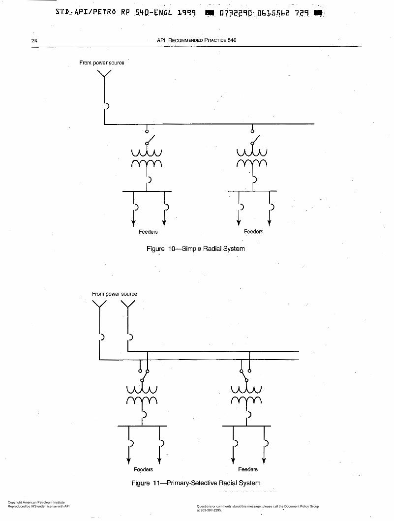
24 API RECOMMENDED PRACTICE 540
From power source
Y '1
¿ A
UL UL
Feeders Feeders
Figure 10-Simple Radial System
From power source
Feeders Feeders
Figure 1 1-Primary-Selective Radial System
Copyright American Petroleum Institute Reproduced by IHS under license with API
Document provided by IHS Licensee=BG Group/5943895100, 01/31/2005 04:58:30 MSTQuestions or comments about this message: please call the Document Policy Groupat 303-397-2295.
--`,`,,,`,`,`,,,```,,``,,`,``,,-`-`,,`,,`,`,,`---
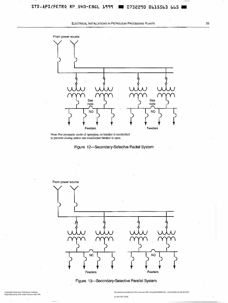
ELECTRICAL INSTALLATIONS IN PETROLEUM PROCESSING PLANTS 25
From power source
I I I I
Note: For automatic mode of operation, tie breaker is interlocked to prevent closing unless one transformer breaker is open.
Figure 12-Secondary-Selective Radial System
From power source
Feeders Feeders
Figure 13-Secondary-Selective Parallel System
Copyright American Petroleum Institute Reproduced by IHS under license with API
Document provided by IHS Licensee=BG Group/5943895100, 01/31/2005 04:58:30 MSTQuestions or comments about this message: please call the Document Policy Groupat 303-397-2295.
--`,`,,,`,`,`,,,```,,``,,`,``,,-`-`,,`,,`,`,,`---
! g. IEEE Std 1015 (Blue Book). h. Protective Relaying for Power Systems, Volume I and Vol- ume II, edited by Stanley H. Horowitz, American Electric Power Service Corporation.15
4.7 SYSTEM PROTECTION
4.7.1 Fault Considerations
When a facility's electric power system has to be designed and the appropriate equipment needs to be selected, the fol- lowing fault considerations should be considered:
a. Possible or likely places where faults may occur. b. Amount of fault current that the system can deliver. c. Possible damage that may result from faults.
4.7.1.1 Location of Faults
Although faults can occur anyplace in an electrical system, the probability of occurrence varies at different locations. Switchgear, transformers, and buses have relatively few short circuits; and rotating machines, when maintained and pro- tected against voltage surges, are not prone to failure. Bare overhead distribution systems, however, experience the high- est incidence of faults.
4.7.1.2 Fault-Current Magnitudes
Devices used for fault-current interruption must have interrupting and momentary withstand ratings that can ade- quately handle the available fault currents. Inadequate rat- ings can result in failure of the equipment to perform its intended function. Such a failure can destroy the equipment and can result in potential danger to personnel and to other equipment.
Interrupting-device ratings should be based on the maxi- mum fault current of the system at the point of application. The magnitude of fault current which the system can deliver depends on the sources of current and the impedance between the sources and the fault. The sources of current include in- plant generators and motors and connections to external power sources such as electric utilities. The fault-current capabilities of simple systems may be hand-calculated; those of more complex systems will require study using computer programs that are readily available. When selecting equip- ment, future expansion of the electrical system must be con- sidered to ensure that ratings are adequate for the future current duty. Driving point voltage (voltage at the time of the fault) must be determined. It is not uncommon to see systems operating at 1 .O5 to l. 10 per unit voltage.
lSAvailable from EEE.
4.7.1.3 Damage From Faults
Faults which are not promptly isolated from the source of power can be very damaging: electrical and other apparatus can be damaged, fires can be started, and lives can be endan- gered. Lengthy production interruptions are a likely result of this kind of damage.
4.7.2 Fault Clearing Considerations
4.7.2.1 Procedure
To properly remove a fault from the electrical system, it must initially be detected by a fault sensing device. The fault sensing device then sends a signal to one or more fault clearing devices which will operate to isolate the faulted segment of the system. This process takes place automati- cally and quickly in order to minimize the damage caused by the fault. The fault clearing devices must have adequate interrupting and momentary withstand ratings as discussed in 4.7.1.2:
4.7.2.2 Dual-Purpose Devices
Some electrical devices provide both the sensing and the interrupting functions in the same enclosure without the inter- action of peripheral devices. Examples of these devices are as . .
follows:
a. Fuses of all voltage ratings. b. Molded-case circuit breakers and insulated-case circuit breakers.
These devices have internal sensors (thermal, magnetic, or static) that detect the flow of fault currents and, through the direct molecular or mechanical action of these sensors, oper- ate to clear the fault.
4.7.2.3 Single-Purpose Devices
Many electrical fault clearing devices receive an electrical signal to operate from a relay or set of relays. These devices take the relay signal, process that signal, and then operate a set of mechanical contacts to interrupt the flow of electric cur- rent running through them. Examples of these fault clearing- devices are as follows:
a. Circuit breakers of all types other than the types discussed in 4.7.2.2. These include sulfur hexafluoride (SFg), oil, air, and vacuum circuit breakers in a variety of configurations. often, these circuit breakers are mounted in a lineup of switchgear, an arrangement discussed in 4.10. b. Circuit switchers which are usually found on high-voltage circuits for transformer and feeder protection.
Since relays are a key element in the proper operation of these protective devices, some of the important consider- ations regarding relays-are addressed in 4.7.3.
Copyright American Petroleum Institute Reproduced by IHS under license with API
Document provided by IHS Licensee=BG Group/5943895100, 01/31/2005 04:58:30 MSTQuestions or comments about this message: please call the Document Policy Groupat 303-397-2295.
--`,`,,,`,`,`,,,```,,``,,`,``,,-`-`,,`,,`,`,,`---
4.7.2.4 Coordination of Devices
Generally, a zone of protection is established around each system element, such as a bus, transmission line, generator, or transformer, and a fault in a zone should be cleared by the fault clearing devices around that particular zone. For the fault clear- ing devices to properly isolate a faulted section of a system, they must be properly coordinated. A coordinated device must protect the equipment in a zone and should be selective with upstream and downstream devices. This means that the protec- tive device closest to a faulted section should open and inter- rupt the flow of fault current before other devices on the electrical system operate. This does not mean that other devices will not see the fault current flowing, but it means that they should not have had time to take any action toward opening to clear the fault. If a malfunction of the devices occurs around a particular zone, fault clearing devices in the next zone upstream should operate to clear a fault. Obviously, the upstream devices should delay long enough to give the primary clearing devices a chance to operate; however, the upstream fault clearing devices should not delay too long or the fault damage could be more extensive.
Selectivity between fault clearing devices in series should be maintained. The procedures for determining coordination margins (time interval between device curves) are outlined in many publications devoted to the subject. Included among these are the following:
a. WEE Std 141. b. IEEE Std 242. c. IEEE Std 399. d. Applied Protective Re1~ying.I~
Fault clearing device coordination is vital to a facility power system. Particular attention must be paid to obtaining optimum settings and to recalculating and maintaining set- tings as system conditions change.
4.7.3 Relaying Considerations
4.7.3.1 Relay Dependability
A relay detects abnormal system conditions and often ini- tiates breaker operation. Although a breaker may be prop- erly selected and applied, it is useless if it fails to operate at the proper time and a nuisance if it operates when it should not because of improper setting or application of the relay.
4.7.3.2 Relay Selection
Electromechanical and static relays must be selected with care because types are available for almost every system requirement. The proper selection and application of relays is important to the electrical system and requires thorough study. Relays associated with facility power systems are used primarily for the protection of feeders, transformers, and rotating machines.
4.7.3.3 Relay Selectivity
Many relays have settings which allow their operating characteristics to be changed. Relays can be made, for example, to operate at different times when installed to look at the same set of abnormal system conditions. Used in conjunction with fault clearing devices, they can be used to establish the coordination of the fault clearing devices discussed in 4.7.2.4. Desired protection can only be ensured by choosing relays of the proper types and opera- tion ranges and by determining the correct relay settings. Careful studies must be made of each switching configura- tion for various plant operating load conditions to arrive at the proper settings that will permit maximum load to be placed on line and carried while still protecting for mini- mum fault levels.
4.7.3.4 Relay Testing and Inspection
Testing and inspection of protective relays for proper set- tings and operation should be conducted when the relays are placed in service; testing and inspection should then be con- ducted at established, intervals throughout the life of the relays. As much as possible, testing should be done by simu- lating appropriate current and voltages on the primaries or secondaries of the instrument transformers that serve the relays. Many static relays have self-test programs to alarm if the relay is malfunctioning.
4.8 FUSES
4.8.1 Uses
Fuses are used on facility power systems to protect equip- ment and cables from overload conditions and to interrupt fault currents when they occur. When applying fuses, single- phasing possibilities should be considered. Since fuses are single-phase devices, only one fuse may blow on a shgle- phase fault, leaving single-phase potential on a polyphase cir- cuit. Also to be considered is that after repeated operation at a current near the fuse’s melting point, the fuse may become damaged and operate quicker than desired.
4.8.2 Availability
Fuses may be obtained in every voltage level up to at least 138,000 V. There are varieties which are current limiting so that the energy allowed to flow during a fault condition is lim- ited to a lower level than available on the supply side of the fuse, and there are many fuses designed for special applica- tions such as for use in motor starter circuits.
4.8.3 Coordination Considerations
The variety of fuses available allows some flexibility in protective device coordination. Each fuse has a time-current characteristic envelope curve which ,is used to develop cmr-
Copyright American Petroleum Institute Reproduced by IHS under license with API
Document provided by IHS Licensee=BG Group/5943895100, 01/31/2005 04:58:30 MSTQuestions or comments about this message: please call the Document Policy Groupat 303-397-2295.
--`,`,,,`,`,`,,,```,,``,,`,``,,-`-`,,`,,`,`,,`---
28 API RECOMMENDED PRACTICE 540
dination plots for the power system. 12t and let-through cur- rents must be considered when coordinating fuses.
4.9 CIRCUIT BREAKERS
4.9.1 Uses
Circuit breakers, used on both AC and DC systems, are widely used in facility power systems. Found at almost .every voltage level on the system, circuit breakers protect electrical system components from overloads and faults and isolate parts of the system when these conditions occur. Many circuit breaker applications involve switchgear, and switchgear applications are discussed in 4.10.
4.9.2 Types
Circuit breakers used on electrical systems with nominal system voltages less than or equal to 600 V come in a variety of styles. Some, like the molded-case circuit breakers, do not depend on external relays for sensing overloads and faults while others, like the air-break power circuit breakers, have .external current sensors and static relay modules for sensing abnormal conditions. These devices are installed in a variety of equipment, such as panelboards, switchboards, and switchgear.
Circuit breakers used on systems with nominal system voltages of 600 V-15,000 V are generally installed in switch- gear lineups. These breakers use relays for sensing fault con- ditions. The interrupting medium is generally air or vacuum in this voltage class.
Circuit breakers used on systems with nominal system voltages of 15,000 V-35,000 V may be installed in switch- gear. Most breakers for higher voltage systems are individual free-standing outdoor types, and these higher voltage devices use oil or SF6 as the interrupting medium. Relays are used for sensing fault conditions at all these installations.
4.9.3 Location
Circuit breakers are not listed by NRTL for direct use in classified locations. They are, therefore, installed in nonclas- sified locations, either indoors or outdoors, or when installed in a classified location, they must be installed in approved enclosures suitable for the location.
4.9.4 Inspection and Testing
Because many types of circuit breakers are available, it is not possible to discuss in this recommended practice inspec- tion and testing procedures for all circuit breakers. A regular preventive maintenance program should be estabfished. The manufacturer's installation and operating instruction books or a reliable electrical testing firm should be consulted, to estab- lish maintenance and testing requirements and intervals.
4.10 SWITCHGEAR
4.1 0.1 General
The term switchgear covers switching and interrupting devices and their combination with control, metering, pro- tection, and regulating devices and also covers the assembly of these devices with associated interconnections, accesso- ries, enclosures, and supporting structures. Switchgear is used primarily in connection with the generation, transmis- sion, distribution, and conversion of electric power. Applica- tions include controlling circuits serving generators, large motors, transformers, power circuit feeders, and other large electrical equipment.
4.1 0.2 Medium-Voltage Switchgear
In general, the 5-kv to 15-kv medum-voltage switchgear used in facilities is the metal-clad type with drawout circuit breakers and all pertinent auxiliaries contained within their own individual enclosures. Switchgear above the 15-kV class may be the metal-clad or stationary type. Other equipment installed in the switchgear is necessary buses, disconnecting devices, current and voltage transformers, control power transformers, interIocks, meters, relays, and control devices. The switchgear is generally in the 5-kv to 38-kv class with current ratings up to 3,000 amperes, and interrupting classifi- cations ranging from 250 MVA to 1,500 MVA.
4.10.3 Low-Voltage Switchgear
Switchgear rated at 600 V is available for small loads that cannot be served economically at 5 k v and above. The pre- ferred construction is metal-enclosed, using air-break or vac- uum, drawout-type low-voltage power circuit breakers. Continuous current ratings are available to 6,000 amps, and interrupting current ratings range from 30,000 amps to 200,000 amps. Integral current limiting fuse devices are used to achieve higher interrupting duties.
4.10.4 Interrupting Medium
There are several options to consider when selecting the interrupting medium for medium-voltage switchgear. Air- break and oil-immersed circuit breakers are rapidly being phased out by vacuum and SF6 circuit breakers. An assess- ment of the circuit breaker installed cost, operating charac- teristics, and maintenance requirements is required and must be evaluated to determine which type should be applied. Low-voltage switchgear is most commonly either air-break or vacuum-break.
Where an interrupting medium is considered for an appli- cation for the first time, interrupting characteristics should be reviewed at rated .conditions. Maintenance procedure details should be fully understood prior to the selection.
Copyright American Petroleum Institute Reproduced by IHS under license with API
Document provided by IHS Licensee=BG Group/5943895100, 01/31/2005 04:58:30 MSTQuestions or comments about this message: please call the Document Policy Groupat 303-397-2295.
--`,`,,,`,`,`,,,```,,``,,`,``,,-`-`,,`,,`,`,,`---
~~
STD.API/PETRO RP 540-ENGL.1999 E 0732290 Ob155b7 Z O O EI.
ELECTRICAL INSTALLATIONS IN PETROLEUM PROCESSING PLANTS 29
4.10.5 Location
Manufacturers do not list switchgear as suitable for use in a classified location. In practice, switchgear that serves process units must be either located adjacent to the classified location or installed in a pressurized room.
Processing plant switchgear frequently takes the form of a unit substation, which consists of a transformer (single- ended) or transformers (double-ended) that supply utilization voltage to a group of feeder circuit breakers. Unit substations may be purchased as neat, compact units well adapted for either indoor or outdoor plant use. Transformers and switch- gear may be purchased separately and installed indoors or outdoors as desired.
4.10.6 Installation Types
4.10.6.1 Indoor Switchgear
with the time interval between inspections varying with environment and service. The range of intervals is usually 1 to 5 years, with experience with the particular installations dictating any changes to the schedule. Preventive mainte- nance should include all tasks necessary to assure the reli- able operation of the switchgear during the maintenance interval. This maintenance should include inspecting the overload unit settings and other breaker parts, such as con- tacts and arc chutes for air circuit breakers; or vacuum inter- rupter, vacuum integrity, and contact erosion indicators on vacuum circuit breakers. Maintenance also includes check- ing the trip devices by a test set available from the equip- ment manufacturer.
4.1 1 TRANSFORMERS
4.1 1.1 General
Indoor switchgear (NEMA 1 or NEMA 12 enclosure) is This information is confined primarily to distribution and not as expensive as outdoor switchgear (NEMA 3R Or 4x power transformers. Other types of transformers which are enclosure); however, the former requires indoor space which applied within the petroleum industry are mentioned briefly, affects the overall cost. The cost of providing the indoor but these other types usually operate as of an electrical location may be offset by the reduced maintenance and equipmentpackage. equipment costs and by the increased reliability resulting from a more benign equipment environment. A common 4-11 .2 Transformer Types location is often used to house both switchgear and motor control equipment. 4.1 1.2.1 Distribution and Power Transformers
4.10.6.2 Outdoor Switchgear
Outdoor switchgear is basically indoor switchgear mounted in a weatherproof enclosure. The following types of enclosures are available:
a. Enclosure without an aisle. b. Enclosure with an aisle in front of the switchgear. c. Enclosure with a common aisle between two switchgear lineups.
An aisle facilitates the maintenance and operation of the switchgear.
4.10.6.3 Electrical Power Centers
The use of prefabricated electrical power centers is appro- priate for some applications where work at the site is to be minimized. These prefabricated electrical power centers are modular structures equipped with lighting, heating, and venti- lating equipment. Requiring only assembly and internal con- nections on site, they can be shipped as a unit or in modular sections with switchgear, motor control centers, and other equipment already installed.
4.10.7 Preventive Maintenance
Preventive maintenance, including inspection and testing of switchgear, should be carried out on a regular schedule,
Distribution and power transformers are used to isolate dif- ferent voltage systems from each other and to reduce or increase voltages to their optimum utilization levels. These transformers may be integral parts of unit substations and motor control centers, or they may be located at a remote site.
Unit substation transformers are mechanically and electri- cally connected to unit substation equipment or motor control centers. Aside from the physical size and certain features of construction, unit substation transformers are applied in the same manner and for the same purposes as distribution and power transformers.
Power transformers are frequently used to step-down plant distribution voltage to motor utilization levels (e.g., 13.8 k v to 4,160 V or 6,600 V). Often, a captive transformer is used to supply a single large motor, usually greater than or equal to 2,500 HP. The added impedance of the captive transformer in the motor supply circuit lowers voltage and starting in-rush current. The captive transformer should be designed for the required motor starting and operating duty. The captive trans- former-motor combination may be selected over the direct- connected motor for reason of design, system stability, or motor economics.
Step-up power transformer or transformedrectifier sets are often used for desalting and precipitation processes where the plant voltage must be increased to the level required at the desalter or precipitator electrodes.
Copyright American Petroleum Institute Reproduced by IHS under license with API
Document provided by IHS Licensee=BG Group/5943895100, 01/31/2005 04:58:30 MSTQuestions or comments about this message: please call the Document Policy Groupat 303-397-2295.
--`,`,,,`,`,`,,,```,,``,,`,``,,-`-`,,`,,`,`,,`---
30 API RECOMMENDED PRACTICE 540
4.1 1.2.2 Instrument Transformers
Instrument transformers are used for metering and relay- ing, have a high degree of accuracy, and have limited capac- ity. The accuracy of transformation depends on the application because meteling and relaying require different accuracies. The degree of accuracy is also subject to the effects of load and fault current.
Voltage transformers are employed to step down primary voltage to a secondary voltage, normally 120 V, at the rated primary voltage. Current transformers are employed to trans- form primary current to a secondary current, normally 5 amps, at the rated primary current. For some applications, current transformers with multiratio p'imary taps are used.
4.1 1.2.3 Autotransformers
The autotransformer is a single-winding transformer in which the lower voltage is obtained by a tap position between the line terminals. Unlike a two-winding distribution or power transformer, a single-winding transformer does not isolate the high-voltage and low-voltage windings.
Autotransformers are frequently used to provide an eco- nomical tie between two systems of different voltage levels (e.g., a 4,160-V to a 2400-V system and a 138-kv to a 69-kv system). They are also used for motor control in some types of reduced voltage starter packages.
4.1 1.2.4 Other Transformers
Other specialty transformers are zigzag grounding, con- stant voltage, and low-noise isolation transformers. Zigzag grounding transformers are used to derive a neutral for sys- tem grounding purposes and can be used to provide a ground connection for delta-connected transformer second- aries. They permit ground-fault relaying and eliminate high transient voltages that can ,occur on ungrounded systems. Constant-voltage transformers provide a stable power sup- ply for instrumentation and other loads requiring a constant voltage. Low-noise isolation transformers are used to supply power to digital-based systems, such as computers, that are highly susceptible to voltage transients. Transformers are frequently applied to provide isolation for the input to adjustable speed drives. A three-winding transformer (a sin- gle primary with a wye- and a delta-connected secondary) can be used to reduce power system harmonics through har- monic current cancellation.
4.1 1.3 Ratings
4.1 1.3.1 Voltage and Frequency
The voltage rating for transformers is determined primarily by the system voltage available and the utilization voltage required. For 60-Hz electric power systems, it is recom-
mended that the voltage rating conform to one of the voltage ratings given in ANSI (34.1.
Consideration in the selection of these voltage ratings could result in procurement and maintenance economies due to the ability to parallel and interchange transformers. Atten- tion to voltage tap ratings will permit added flexibility in matching transformers to system voltages.
Due to a worldwide lack of standardization of AC system frequency, the transformer frequency should always be specified.
4.1 1.3.2 Capacity and Duty
The recommended kilovolt-ampere (kVA) ratings of trans- formers are given in ANSI or NEMA standards. These ratings should be on a continuous basis without exceeding the tem- perature limitations for continuous-rated transformers. Cap- tive transformer design should take into account the magnitude of starting current, the duration of motor accelera- tion, and the permissible starting frequency of the motor.
4.1 1.3.3 Temperature Rise
The rated kVA of a transformer is the load which can be carried continuously at rated voltage and frequency without exceeding the specified temperature rise. A transformer . .
should have a normal life at its rated kVA if the specified tem- perature rise is not exceeded, the ambient temperature does not peak above 40°C (104"F), and the ambient temperature does not rise above 30°C (86°F) for a 24-hour average.
Oil-filled transformers are limited to a winding tempera- ture rise, as measured by resistance, of 65°C (1 17°F) or 55"C/ 65°C (99"F/117"F) and a hottest-spot winding temperature rise of 80°C (144°F). Dry-type transformers are divided into the following temperature rise specifications:
a. Class 150 C has Class B winding insulation and is lim- ited to an average rise of 80°C (144°F) with a hot spot of 110°C (198°F). b. Class 185 C has Class F winding insulation and is limited to an average rise of 115°C (207°F) with a hot spot of 145°C (261°F). c. Class 220 C has Class H winding insulation and is limited to an average rise of 150°C (270°F) with a hot spot of 180°C (324°F).
More detailed information on temperature rise specifica- tions is contained in IEEE C57.91 and IEEE C57.96.
If operated outside of these temperature limitations, the transformer must be rerated on the basis of the actual load cycle and ambient temperature to attain its normal life expect- ancy. The transformer manufacturer should be consulted for these figures. As a rule of thumb, insulation life is cut in half for each 10°C rise in operating temperature.
When load is applied to a transformer, the heating and cooling curves vary exponentially. The time constant for the
Copyright American Petroleum Institute Reproduced by IHS under license with API
Document provided by IHS Licensee=BG Group/5943895100, 01/31/2005 04:58:30 MSTQuestions or comments about this message: please call the Document Policy Groupat 303-397-2295.
--`,`,,,`,`,`,,,```,,``,,`,``,,-`-`,,`,,`,`,,`---
~ ~
STD-APIIPETRO RP 540-ENGL L999 11111 0732270 0~635569 083 E
ELECTRICAL INSTALLATIONS IN PETROLEUM PROCESSING PLANTS 31
windings is 5 to 10 minutes and for the oil is 2 to 4 hours. A time equal to approximately five time constants is required for the items to reach their ultimate temperature. Short-time overloads of 1 hour or less are permissible, however, as long as the hottest spot copper temperature does not exceed 150°C (302°F) for an oil-filled transformer. Overloads of more than one-hour in duration should be avoided.
Transformers operated to altitudes greater than 1,000 m (3,300 ft) above sea level are subject to special rating correc- tion factors which may be obtained from the manufacturer.
4.1 1.3.4 Insulation
The basic impulse level @IL), which indicates a trans- former’s ability to withstand transient over-voltages, and the applicable manufacturer’s test voltages are given in IEEE C57.12.00 for liquid-filled transformers, and IEEE C57.12.01 for dry-type transformers. The dielectric strength of transform- ers that depend on air for insulation decreases as altitude increases. Insulation-class correction factors for altitudes greater than 1,000 m (3,300 feet) are covered in IEEE C57.12.01.
4.11.3.5 Efficiency and Regulation
Efficiency and regulation are fixed by the manufacturer’s design, although more efficient designs are available at higher cost, if the loss evaluation warrants them.
4.1 1.3.6 Impedance
The impedance is expressed as a percentage of the trans- former base kilovolt-ampere rating and is determined by the internal characteristics of the transformer, which include its core design, resistance, and geometry of windings. The manu- facturer’s standard impedance, in accordance with ANSI stan- dards, is normally acceptable to facilitate parallel operation and minimize cost. In some instances, it may be desirable to install a transformer with greater-than-standard impedance to limit the short-circuit duty on secondary switchgear. In other instances, a transformer with lower-than-standard impedance is used to facilitate motor starting by reducing the voltage drop.
4.1 1.4 Applications
4.1 1.4.1 Location
Transformers and associated secondary switchgear should be located as near to their load centers as practical while mini- mizing exposure to fire and mechanical damage. The location should preferably be unclassified. In cases where the trans- former must be in a classified location, all auxiliary devices associated with the transformer must be suitable for the classi- fication. For Class I, Division 2, or Zone 2 locations, it is some- times practical to locate the transformer outside a pressurized
switchgear room with a secondary throat connection for a busway supply through the wall of the room to the switchgear.
4.1 1.4.2 Grounding
Neutral grounding of transformer secondaries should be considered. The type of grounding chosen is based on factors such as voltage levels, ground-fault levels, and continuity of service. The neutral ground is obtained by bringing out the neutral connection on a wye-connected secondary or by using a zigzag transformer on a delta-connected secondary. The neutral is either solidly grounded or grounded through resis- tance or reactance.
4.1 1.4.3 Parallel Operation
Proper operation of parallel transformers requires that the transfo1mers be connected properly and that their characteris- tics be within certain tolerances-refer to IEEE C57.12.00 and IEEE C57.12.01 for acceptable tolerances for parallel operation. To divide the connected load according to the rat- ing of the parallel banks, the following must be the same: the internal impedance, the transformation ratio, and the phase relationship. It is not possible to parallel delta-wye or wye- delta banks with a delta-delta bank because of the 30” phase shift that is present in the secondary.
4.1 1.4.4 Testing and Maintenance
A systematic testing and maintenance program should be established for transformers. It should include the inspection and cleaning of bushings, the testing and gas analysis of trans- former oil, and the vacuum cleaning of dry-type transformers. The manufacturer’s test report for each transformer should be kept on record. This report contains results of dielectric tests and measurements of resistance, excitation current, impedance, ratio, temperature rise, polarity, and phase relation. The dielec- tric strength of new transformer oil should not be less than 30 k v when measured in accordance with ASTM D877. Refer to IEEE C57.106 for mineral oil testing, to BEE C57.111 for silicone fluid testing, and to IEW C57.121 for Less Flammable Hydrocarbon Huid testing.
When dielectric testing of transformer windings is per- formed, the test parameter limitations set forth in the stan- dards should not be exceeded (see 4.1 1.3.4).
Dielectric testing of bushings is also covered by standards. High-voltage DC test equipment is available to provide non- destructive and accurate testing of insulation. This method of testing is preferable to high-voltage AC test procedures. Power factor tests are also used to indicate the condition of transformer insulation. When a program of power factor test- ing is planned, the transformer factory testing should include a power factor test so that the results will be available for comparison with later field testing.
Copyright American Petroleum Institute Reproduced by IHS under license with API
Document provided by IHS Licensee=BG Group/5943895100, 01/31/2005 04:58:30 MSTQuestions or comments about this message: please call the Document Policy Groupat 303-397-2295.
--`,`,,,`,`,`,,,```,,``,,`,``,,-`-`,,`,,`,`,,`---
32 API RECOMMENDED PRACTICE 540
4.1 1.5 Construction and Accessories
4.1 1.5.1 Oil-Filled Transformers
Transformer oil is used to insulate and cool the windings and to protect the core and windings from corrosive and hazardous vapors. Transformer oil should include a suitable oxygen inhibitor to prevent deterioration of the dielectric. The sealed-tank system is standard for transformers rated 2,500 kVA, 200-kv basic impulse level and less, and is often used on larger sizes as well. Inert-gas-pressurized sealed tanks are sometimes provided on larger or critical- service transformers.
Standard accessories for oil-filled transformers include a no-load tap changer, a ground pad, a nameplate, a liquid- level gauge, an oil temperature indicator, a drain valve, a top filter valve, a pressure-vacuum gauge, and jack bosses. Optional features pertain to the type of bushings, fan con- trols, winding temperature indication, sudden pressure relay, terminal blocks, junction boxes, disconnect switches, and throat connections. Where applicable, terminal cham- bers must allow adequate space for stress-relief terminations on shielded cable. Current and voltage transformers, to serve metering and relaying, are often provided in special, separate termination chambers. Multi-ratio current trans- formers are often located within the transformer tank. Con- sideration should be given to a hottest-spot temperature detector where the system operation may subject the trans- former to emergency loading conditions (e.g., where auto- matic bus transfer between two transformers is provided). Transformer gauges can be provided with alarm contacts to allow remote annunciation of transformer problems. All transformer accessories must be suitable for the area classi- fication where the transformer is to be installed.
4.1 1.5.2 Transformer Fluid
4.1 1.5.2.1 Mineral Oil-Filled Transformers
Regulations require users of transformers containing poly- chlorinated biphenyls (PCBs) to maintain specific records, to comply with specified procedures in case of leakage and for disposal, and to fulfill other requirements. Users of PCB-filled or PCB-contaminated oil-filled transformers should consult applicable federal and state regulations. Transformers contain- ing PCBs are no longer manufactured because of federal envi- ronmental and health regulations (see 40 CFR Part 761.).
4.1 1.5.2.2 Less-Flammable Hydrocarbon Fluid and Silicon Insulating Fluid-Filled Transformers
Transformers with less-flammable hydrocarbon fluid and silicon insulating fluid insulation media, are available for use where mineral oil-filled transformers would constitute a
fire hazard, and are substitutes for the PCB-type transform- ers. The less-flammable, hydrocarbon type has several spe- cific restrictions on indoor use; while the silicon insulating fluid-type may be used indoors with only the same vault requirement for ratings over 35 kV that applies for PCB- filled transformers (see NFPA 70). Silicon insulating fluid is generally not used above 35 kv.
4.1 1.5.3 Dry-TypeTransformers
Ventilated dry-type transformers, as distinguished from sealed dry-type transformers, are used for indoor locations. Weatherproof units are available for outdoor use, primarily for lighting services where the primary voltage is usually 480 V. They are lightweight compared to oil-filled trans- formers, making them more economical to install. Only minimum maintenance, including a periodic cleaning of the windings, is required.
Ventilated dry-type transformers have several disadvan- tages, compared with liquid- or fluid-filled transformers:
a. They have a lower standard basic impulse level. b. They lack an overload rating. c. Their use may result in a higher noise level. d. Their windings are more exposed to the environment.
I .
Surge capacitors and arresters can be installed to compen- ,
sate for the lower basic impulse level, and forced-air cooling equipment can be used to increase transformer capacity. Where the environment presents corrosive vapors, the trans- formers can be obtained as completely sealed, nitrogen-pres- surized units.
4.1 1.5.4 Cast-Coil Transformers
Cast-coil transformers are fabricated with a solid dielectric completely encapsulating the primary and secondary coils, which are mounted in a suitable, ventilated enclosure. This results in a transformer that is contaminant and moisture resistant, has low maintenance, and has impulse ratings com- parable to other dry-type transformers.
4.1 1.5.5 Transformer Taps
Transformers should be provided with fully rated kVA taps suitable for tap changing under no-load conditions. Tap changers are designed in uniform 2.5% or 5% steps above and below rated voltage. The number of taps above and below rated voltage and their magnitude will depend on individual requirements. Two 2.5% taps above and below rated voltage are often specified.
Large power transformers may be equipped with auto- matic, fully rated kilovolt-ampere taps suitable for adjusting voltage under full-load conditions.
Copyright American Petroleum Institute Reproduced by IHS under license with API
Document provided by IHS Licensee=BG Group/5943895100, 01/31/2005 04:58:30 MSTQuestions or comments about this message: please call the Document Policy Groupat 303-397-2295.
--`,`,,,`,`,`,,,```,,``,,`,``,,-`-`,,`,,`,`,,`---
ELECTRICAL INSTALLATIONS IN PETROLEUM PROCESSING PLANTS 33
4.1 1.5.6 Forced-Air Cooling
The kilovolt-ampere rating of the transformer is deter- mined by the temperature rating of the winding insulation. One means of increasing transformer capacity is to keep the winding insulation within its rating by increasing the effective cooling of the transformer. This can be accomplished with forced-air cooling. Where load growth is anticipated, consid- eration should be given to providing fans for forced-air cool- ing; or to providing the brackets, temperature switch, and wiring necessary to accommodate the future addition of fans.
Forced-air cooling of a transformer also allows increased capacity while holding the impedance to a value that permits the use of secondary switching equipment of lesser intermpt- ing capacity. Forced-air-cooled transformers should be con- sidered when automatic bus transfer is provided between the secondaries of two transformers. With this arrangement, the transformer may be more economically loaded under normal operation. Forced-air cooling also permits carrying additional load, (up to 2?? on'large transformers) without exceeding the specified temperature limits.
4.1 1 S.7 Forced-Oil Cooling
Forced-oil cooling is another method of increasing trans- ' - former capacity because it reduces oil temperature. The
pumping and circulating of oil is common in the design of larger (above 8 MVA) power transformers.
4.1 1.6 Loading
A properly designed electrical system will seldom require the emergency loading of transformers. System growth may, however, make such loading necessary, in which case IEEE C57.91 should be consulted.
4.12 OVERHEAD ELECTRIC POWER DISTRIBUTION
4.12.1 General
The use of open conductors, pre-assembled or field-spun aerial cable, and spacer cable supported by poles or struc- tures for distribution systems outside of process limits, util- ity areas, and operational areas should be subject to engineering approval. Overhead electrical distribution sys- tems should be designed and installed in accordance with the requirements of NFPA 70, ANSUEEE C2, and applica- ble state and local codes.
4.12.2 Materials
Most pole-line materials conform to the standards and sug- gested specifications of the Edison Electric Institute (EEI)16 or
I
~ 16Edison Electric Institute, 701 Pennsylvania Avenue, Washington, D.C. 20004.
are similar in design, material, and workmanship. Special structures, such as A-Frame or H-Frame structures, may be required for the support of a line or a group of lines whose loading is in excess of that which can be safely or economically supported on single poles or other simple structures.
4.12.3 Aerial Cable
Aerial cable provides an alternative to open conductor dis- hibution. Aerial cable is available in single- and three-con- ductor types, shielded or nonshielded; and aerial cable with a self-supporting synthetic jacket is preferred. Messengers of self-supporting cable should be grounded at frequent inter- vals. Surge arresters should be installed at terminal poles where aerial cable is connected to open conductors.
4.12.4 Metal-Clad Cable
Metal-clad (Type MC) cable supported by a messenger may be used as an alternative to aerial cable. Metal-clad cable consists of one or more conductors with necessary insulation, shielding, and fillers over which a suitable metallic sheath is applied. A jacket is normally supplied over the sheath. Gener- ally, this sheath should not be relied on as a grounding con- ductor; a grounding conductor should be installed in the cable interstices during manufacture.
4.12.5 Accessibility
All parts of the overhead distribution system that must be examined or adjusted during normal operation should be readily accessible to authorized personnel. Provisions should be made to ensure adequate climbing spaces, working spaces, working facilities, and clearances between conductors. The electrical clearances must be established in accordance with ANSIAEEE C2 and any applicable state and local codes.
4.12.6 Isolation and Guarding
To provide for the safety of employees not authorized to approach conductors and other current-carrying parts of elec- trical supply lines, the arrangement of live parts must ensure adequate clearance to ground, or guards should be installed to isolate these parts effectively from accidental contact.
4.12.7 Grounding of Circuits and Equipment
Grounding of circuits and equipment should conform to ANSUEEE C2 and any applicable state and local codes. Metallic sheaths, conduits, metal supports, fixtures, frames, cases, and other similar noncurrent carrying parts should be properly grounded. A temporary ground for maintenance pur- poses should consist of a secure mechanical connection to a buried metallic structure or driven ground rod. Resistance of such a ground should limit touch and step potentials to acceptable levels in accordance with IEEE 80.
Copyright American Petroleum Institute Reproduced by IHS under license with API
Document provided by IHS Licensee=BG Group/5943895100, 01/31/2005 04:58:30 MSTQuestions or comments about this message: please call the Document Policy Groupat 303-397-2295.
--`,`,,,`,`,`,,,```,,``,,`,``,,-`-`,,`,,`,`,,`---
STD.API/-PETRO RP 540-ENGL 4997 - U 07322.70 0645.572 67.8 .!m.
34 API. RECOMMENDED PRACTICE 540
4.12.8 Clearances
The clearances specified for conductors in ANSVIEEE C2, Section 23, are a minimum recommendation. Any applicable local and state requirements must also be considered.
4.12.9 Location
4.12.9.1 Routing
The recommended routing for overhead lines is along facility roads or streets. When lines must be located in tank areas or other locations that are not reached by roadways, it is recommended that the lines be routed along earthen fire- walls, the toe of dikes, or other logical routes. The location of overhead lines should comply with the requirements of applicable fire codes; and wherever possible, lines should be routed so as to minimize exposure to damage from fires originating in equipment or structures along their routes. Lines should not be run in areas where interference with crane booms and similar apparatus is likely during normal plant operation or routine maintenance.
4.1 2.9.2 Water Spray Exposure
Overhead lines should be located far enough from cooling towers, spray ponds, and other sources of water spray to avoid fouling their insulation and corroding their metal parts. When this is not practical, the lines should be designed and con-
structed to withstand the particular type of exposure to which they will be subjected. This may require overinsulation of the exposed sections of lines, the use of materials to withstand the corrosive effects of the spray, or other measures.
4.12.9.3 Petrochemical Exposure
When overhead lines are exposed to petrochemicals or other similar contaminants, the lines should be designed to withstand the effects of such contaminants. Specially approved silicon-type grease on the insulators, bushings, and similar items provides a strong deterrent to current leakage and insulator flashover. Silicon tends to absorb the foreign matter deposited on the dielectric material and continually provides a nonconducting, water-repellent exterior seal for the equipment.
4.12.9.4 Lines Adjacent to an NFPA 70 Defined Class I Location
When installed adjacent to or traversing Class I locations, overhead lines should be placed so that the current-canying components will be outside the space that may contain flam- mable gases or vapors (see API Rp 500). Conventional over- head-line construction normally meets this requirement ,,.
because of the isolation naturally afforded by the horizontal distance from, or elevation above, the classified location.
Copyright American Petroleum Institute Reproduced by IHS under license with API
Document provided by IHS Licensee=BG Group/5943895100, 01/31/2005 04:58:30 MSTQuestions or comments about this message: please call the Document Policy Groupat 303-397-2295.
--`,`,,,`,`,`,,,```,,``,,`,``,,-`-`,,`,,`,`,,`---
SECTION 5-GROUNDING AND LIGHTNING PROTECTION
5.1 PURPOSE The following grounding practice is recommended:
This section provides a guide to the general principles of grounding and lightning protection as they apply to petro- leum processing plants.
5.2 SCOPE
This section is limited to the consideration of grounding practices in the following categories:
a. System grounding: The protection of electrical equipment and the reliability of an electrical system. b. Equipment grounding: The protection of personnel against electric shock. c. Lightning protection against the hazards of fire and explo- sion, as well as damage to electrical equipment, caused by lightning.
5.3 STATIC ELECTRICITY AND STRAY CURRENTS
The application of bonding and grounding for protection against the effects of static electricity and stray currents (such as currents associated with cathodic protection) is not covered in this section. These important subjects are discussed in API RP 2003 and NFPA 77.
5.4 SYSTEM GROUNDING
5.4.1 General
Electric power distribution system grounding is concerned with the nature and location of an intentional conductive con- nection between the neutral (or derived neutral) of the system and the ground (earth). The common classifications of grounding methods used in industrial plant power distribution systems are as follows:
a. Ungrounded. b. Low-resistance grounded. c. High-resistance grounded. d. Reactance grounded. e. Solidly grounded.
The nature of system grounding significantly affects the magnitude of line-to-ground voltages under both steady-state and transient conditions. Without system grounding, severe overvoltages can occur; reducing insulation life and present- ing a hazard to personnel. System grounding can control these overvoltages to acceptable levels. Further, NFPA 70 requires that certain systems be solidly grounded.
For these reasons, some type of system grounding is gener- ally recommended.
a. Systems rated at less than or equal to 480 V that supply phase-to-neutral loads must be solidly grounded. These include 120/240-V, single-phase, three-wire systems; 208Y/ 120-V, three-phase, four-wire systems; and 480Y/277-V, three-phase, four-wire systems. b. Low-voltage (480-V and 600-V), three-wire systems should be either high-resistance grounded or solidly grounded. c. All other plant distribution systems may be resistance grounded. These include 2,400 V through 34,500-V, three- phase, three-wire systems. (Open. wire distribution may require solid grounding.)
A full discussion of the relative merits of the various sys- tems is not within the scope of this section, but a brief sum- mary of the principal features is included. A more extensive discussion of the subject can be found in IEEE Std 142.
5.4.2 Ungrounded System
In an ungrounded system, there is no intentional connec- tion to ground, but the system is capacitively grounded because of the capacitance coupling to ground of every ener- gized conductor. The operating advantage of this system is that a single line-to-ground fault will not result in a trip-out of the circuit because there is only a minor charging current flowing to ground. During such a fault, the other phases will be subject to line-to-ground voltages equal to the full line-to- line voltage; therefore, insulation for equipment used in such a system must be properly rated for this condition. Further, because of the capacitance coupling to ground, the ungrounded system is subject to overvoltages (five times nor- mal or more) as a result of an intermittent-contact ground fault (arcing ground) or a high inductive-reactance connected from one phase to ground.
The advantage of the ungrounded system will be lost if the ground is allowed to persist until a second ground occurs. A second ground would cause an outage if it is on another phase. An adequate ground detection system, along with a program for removing grounds, is essential for satisfactory operation of an ungrounded system.
5.4.3 Grounded Systems
Resistance grounding employs a resistor connected between the system neutral and ground. This resistor is in parallel with the total system-to-ground capacitive reactance.
The high-resistance grounded system employs a resistance value equal to or slightly less than the total system-to-ground capacitive reactance. (The size of the resistor is normally expressed in amperes.) This will limit the ground-fault current to a few amperes and will eliminate the high transient overvolt-
35
Copyright American Petroleum Institute Reproduced by IHS under license with API
Document provided by IHS Licensee=BG Group/5943895100, 01/31/2005 04:58:30 MSTQuestions or comments about this message: please call the Document Policy Groupat 303-397-2295.
--`,`,,,`,`,`,,,```,,``,,`,``,,-`-`,,`,,`,`,,`---
36 API RECOMMENDED PRACTICE 540
ages that can be created by an inductive reactance connected ftom one phase to ground or from an intermittent-contact ground fault. The high-resistance grounded system also pro- vides a convenient means for detection of and alam on a ground fault and facilitates the use of equipment which can determine the fault location without electrical system shut- down. In addition, this system is similar to the ungrounded sys- tem in that it can continue operation with a single line-to- ground fault if the maximum fault current (and total system-to- ground capacitive charging current) is limited to less than 10 amps (see IEEE 142 for additional information). The ground fault, once detected, should be cleared. as soon as possible because the system is not designed to operate with the ground fault condition indefinitely.
The low-resistance grounded system uses a value of resis- tance that is sized to give a ground-fault current value suit- able for relaying purposes (see IEEE 32 for resistor time rating). Typical current values will range from 200 amps on
' systems using sensitive ,window-type current transformer ground-sensor relaying to 2,000 amps on the larger systems using ground-responsive relays connected in current trans- former residual circuits. This system provides a controlled value of ground-fault current and eliminates the overvoltage problems of the ungrounded system, but the action of a three phase circuit-switching device is required to clear a single line-to-ground fault.
Installation of resistance-grounded systems requires that equipment basic impulse levels as well as the application of surge arresters be reviewed carefully.
The solidly grounded system gives the greatest control of overvoltages but develops the highest ground-fault currents. These high currents may cause damage in equipment and may create other shock-hazard problems for personnel if equipment grounding is inadequate. However, the high magnitude ground current may be desirable to ensure effec- tive operation of phase-overcurrent trips or interrupters.
Cable shields must be sized to carry the available ground- fault current for the duration of the'fault without exceeding cable thermal limitations.
Reactance-grounded systems are not ordinarily employed in industrial power systems and will not be discussed here.
5.5 EQUIPMENT GROUNDING
5.5.1 Purpose
Equipment grounding accomplishes the following:
a. Ensures that all of the parts of a structure or an equipment enclosure are not at a voltage above ground that would be dangerous to personnel. Adequate ground connections and devices should to ensure that abnormal conditions, such as ground faults or lightning strokes, will not raise the potential of the structure or enclosure to a dangerous level.
b. Provides an effective path over which fault currents involving ground can flow without sparking or overheating to avoid ignition of combustible atmospheres or materials.
5.5.2 Grounded Equipment
The metal framework of all buildings and structures hous- ing or supporting electrical equipment and all noncurrent- carrying metal parts of electrical equipment and devices should be grounded by connection to a grounding system. In general, equipment grounding conductors should be con- nected as directly as practicable to the electrical system ground. Routing the grounding conductors as close as practi- cable to supply conductors will minimize the voltage drop under fault conditions.
5.5.3 Equipment Grounding System
The principal requirement of an equipment grounding sys- tem is to maintain the resistance to earth of structures and equipment enclosures at the lowest practicable value. With an adequate system, the potential to ground during fault condi- tions will not be dangerous to personnel (because of equaliz- ing of potentials) and equipment, and protective devices will operate properly.
ways. The grounding system for a large or complex plant may involve an extensive network of equipment enclosures and structure ground grids interconnected by cables to provide an overall plant-grounding system. Specific requirements for grounding systems are given in NFPA 70, and detailed infor- matiòn is included in IEEE Std 142.
5.5.4 Specific Grounding Applications
5.5.4.1 Structures and Process Equipment
Grounding-system connections may be made in various .'
Steel building frameworks, switchgear structures, and similar installations should be grounded at several points (at least two per structure) with substantial connection to the grounding system grid. Tanks, vessels, stacks, exchangers, and similar equipment not directly supported by or bolted to a grounded supporting structure should be grounded using a minimum of two connections to the grounding system grid. Special attention should be paid to piping systems to assure the pipe is adequately grounded. Inadequate grounding could result in a difference of potential if for example the pipe was separated at a flange to replace a gasket. This could result in arcing, sparking, or a shocking an employee performing the work.
5.5.4.2 Motors and Generators
Motor and generator enclosures should be connected to the overall plant grounding system. This connection is accom- plished with a mechanically and electrically continuous
Copyright American Petroleum Institute Reproduced by IHS under license with API
Document provided by IHS Licensee=BG Group/5943895100, 01/31/2005 04:58:30 MSTQuestions or comments about this message: please call the Document Policy Groupat 303-397-2295.
--`,`,,,`,`,`,,,```,,``,,`,``,,-`-`,,`,,`,`,,`---
STD.API/PETRO RP 540-ENGL '1999 S 0732290 0635575 387 m
ELECTRICAL lNSTALLATlONS IN PETROLEUM PROCESSING PLANTS 37
equipment-grounding conductor that is routed with the phase conductors of the machine. This may be a conductor run with phase conductors inside a conduit, a continuous-threaded rigid conduit system, a cable tray system, or another NFF'A- 70-approved method. In any case, the grounding connection must provide a low-impedance circuit from the machine enclosure back to the electrical system ground. Where con- duit or trays are used, joints must be made up tightly, and bonding jumpers should be installed at expansion joints and similar locations. The bonding jumpers should be inspected periodically to insure a low impedance connection.
Supplemental grounding protection should be provided by connecting an additional grounding conductor from each machine to the local grounding system grid. The purpose of this connection is to equalize potentials in the immediate vicinity of each machine.
5.5.4.3 Metallic-Sheathed and Metallic-Shielded Cables
The metallic sheath and metallic shield (if applicable) of any power cable should be continuous over the entire run and should be grounded at each end. Grounding of the shield at both ends may require the cable to be derated due to circulating currents. Grounding at one end is permissible if a 25-V gradi- ent is not exceeded (see IEEE Std 422 for method of estimating shield voltages). If any metallic-sheathed or metallic-shielded cables are spliced, care must be taken to obtain continuity as well as an effective physical connection with the metallic sheath or shield at the splice. Where metallic armor is used over metallic sheath, sheath and armor should be bonded together and connected to the ground system at each end of the cable and at any accessible splices. The metallic sheath on metal-clad cable may also be used as an equipment- grounding conductor if the sheath is a continuous corrugated tube. However, a sepa- rate grounding conductor installed in the cable interstices dur- ing manufacture is recommended. The distinctions between sheaths, armoring, and shields can be obscure. An overall welded metal covering is referred to as a sheath but it may act as an armor and a shield (see IEEE Std 100 for additional infor- mation). Adjustable speed drive applications may require that one end of the cable metallic shield remain ungrounded to pre- vent common mode voltages and circulating ground currents.
5.5.4.4 Conductor Enclosures
NFPA 70 requires that exposed metallic noncurrent-carry- ing enclosures of electrical devices be grounded. This includes conduit, wireways, and similar wiring materials. Where the continuity of the enclosure is assured by its con- struction, a grounding connection at its termination points will be adequate. If continuity is not assured by the construc- tion, care must be taken to provide adequate connections of all sections to the grounding system grid.
5.5.4.5 Enclosures for Electrical Equipment
Switchgear, control centers, and similar electrical equip- ment should include a ground bus. Where the equipment con- sists of a lineup of two or more sections, two grounding connections to the grounding system grid, one on each end of the ground bus, are recommended.
5.5.4.6 Fences
Metal fences and gates enclosing electrical equipment or substations must be connected to the grounding system grid. A number of factors are involved here, including the resis- tance to ground of the substation grounding system, the dis- tance of the fence from grounding electrodes, and voltage gradients in the soil. (For additional information, see IEEE Std 80 and Std 142.)
5.5.5 Portable Electrical Equipment
This paragraph is limited to consideration of portable elec- trical equipment operating at less than or equal to 600 volts; portable equipment operating at higher voltages is applied infrequently and requires special consideration. IEEE Std 142 provides information on portable electrical equipment operat- ing at higher voltages.
Portable electrical equipment poses one of the greatest potential hazards to personnel, so it is mandatory that the enclosures of portable equipment of any type be maintained at ground potential or be protected by an approved system of double insulation.
Portable electrical equipment that is without double insula- tion and is operating above 50 V must be provided with a cord containing a separate grounding conductor which terminates in a grounding-type plug that is used with a matching receptacle. The grounding contact of the receptacle must be properly tied to a grounding system. NFPA 70 requires ground-fault circuit interrupters for all 125 V single-phase 15 amp and 20 amp receptacle outlets on temporary wiring used for maintenance or construction. An assured grounding program is an acceptable alternative to ground-fault circuit interrupters (for additional information see NFPA 70, 305-6). The ground-fault circuit interrupter is for personnel safety and is not to be confused with ground-fault protection of equipment requirements for items such as electrical resistance heating elements.
5.5.6 Instrument Grounding
Special considerations apply to instrument grounding. All grounding systems should be tied together in accordance with NFPA 70. In general, a power supply, equipment, and cable shields should be brought to a single point on the overall plant grounding system (procedures are necessary to allow for safe troubleshooting that may require a momentary separation of the tie to the overall plant grounding system). ( S e e 9.8 and IEEE Stds 518 and 1100 for additional information.)
Copyright American Petroleum Institute Reproduced by IHS under license with API
Document provided by IHS Licensee=BG Group/5943895100, 01/31/2005 04:58:30 MSTQuestions or comments about this message: please call the Document Policy Groupat 303-397-2295.
--`,`,,,`,`,`,,,```,,``,,`,``,,-`-`,,`,,`,`,,`---
1 STD-API /PET.RO RP, .540-ENGL 1999 I 073227.0 Ob35576 213' mi
38 API RECOMMENDED PRACTICE 540
I 5.6 CONNECTIONS TO EARTH briefly in IEEE Std 142, and in more detail in the Standard
5.6.1 Acceptable Ground Resistance
Ideally, a ground connection would have zero resistance, but this is impossible. The resistance of a ground connection is a function of soil resistivity and the geometry of the grounding system. In soils of high resistivity, extensive arrangements may be required to obtain an acceptable low- resistance ground.
The allowable resistance varies inversely with the fault cur- rent to ground: the larger the fault curient, the lower the resis- tance. For large substations and generating stations, the resistance of the system grounding grid should not exceed 1 ohm. For smaller substations and for industrial plants, a resis- 'tance of less than 5 ohms should be obtained, if practicable. NFPA 70 approves the use of a single-made electrode if its resistance does not exceed 25 ohms.
5.6.2 Grounding Electrodes
Driven ground rods, 5/8 to 1 in. in diameter, and 8 or 10 ft long, are the most common type of grounding electrodes; however, a single ground rod is not adequate when relatively low resistance is required. A single 3/4-in. x 10-ft ground rod will have a resistance to ground of over 6 ohms, even in soil of low resistivity (2,000 ohm-cm). A number of rods con- nected by buried cable can be used to obtain lower resistance, and longer rods can be used where soil conditions permit; however, because of mutual effects, ground resistance does not decrease in direct proportion to the number or length of rods. Buried metallic piping or other existing underground metallic structures, including concrete-encased electrodes, for example, rebar in concrete foundations (see NFPA 70, Article 250), are also frequently used as grounding electrodes. Ground mats consisting of buried cables with or without ground rods at cable intersections commonly form a portion of the grounding electrode system used at substations. ( S e e IEEE Std 142 for additional information.)
5.6.3 Step and Touch Potentials
Where current flows into the soil from a grounding elec- trode, potential gradients are created in the soil. The ground- ing configuration should ensure that the potential gradients will not create a hazard to personnel standing or walking on the ground in the vicinity of a grounding electrode, or touch- ing a grounded structure carrying ground current. (See IEEE
Handbook For Electrical Engineers?
5.6.5 Corrosion Problems
Copper is commonly used for grounding system grids because of its resistance to corrosion and high conductivity. Because of the galvanic,couple between copper and steel, an extensive copper grounding system grid may accelerate cor- rosion of steel piping and other buried structures that are connected to the system. Under this condition, galvanized steel ground rods and insulated or coated copper conductors could be used, but care must be taken to ensure that the grounding electrodes do not con-ode and reduce their effec- tiveness; and that the use of insulated or coated conductors does not prevent the overall grounding system from main- taining safe step and touch potentials. Cathodic protection of the buried steel subject to corrosion should be considered to alleviate this problem.
5.7 LIGHTNING PROTECTION
5.7.1 General
Lightning is a very large' electrical discharge in the atmo- sphere between the earth and a charged cloud or between two oppositely charged clouds. The energy in a lightning stroke can readily ignite flammable vapors; and damage to equipment and structures can result from the flow of lightning discharge cur- rent through any resistance in its path. Lightning protection systems use air terminals (rods, masts, or overhead ground wires) to intercept lightning strokes and to divert the lightning current to ground through circuits of low electrical impedance.
5.7.2 Zone of Protection
The zone of protection of an air terminal is defined by a circular arc concave upward, passing through the tip of the air terminal and tangent to the ground plane. For complete pro- tection, the radius of the arc must be less than the striking dis- tance of the lightning stroke. In practice, it is conservative to use a radius of 30 m (100 fi). For air terminals less than 15 m (50 ft) above the ground, the zone of protection may be assumed to be a cone with its apex at the top of the air tenni- na1 and a base radius equal to the air terminal height. All structures completely within the zone of protection may be considered essentially immune from direct lightning strokes. (See NFPA 780 for additional information.)
Std 80 for additional information.) 5.7.3 Need for Protection
5.6.4 Ground Resistance Measurement A number of factors should be taken into consideration when deciding whether or not lightning protection devices are
h many installations, it is necessary to measure the resis- The major factors to be are as follows~ tance to earth of the grounding. system to determine if the
I
I actual value of this re&tance within design limits. Meth- a. The frequency and severity of thunderstorms. ods for measuring ground network resistance are discussed b. Personnel hazards.
Copyright American Petroleum Institute Reproduced by IHS under license with API
Document provided by IHS Licensee=BG Group/5943895100, 01/31/2005 04:58:30 MSTQuestions or comments about this message: please call the Document Policy Groupat 303-397-2295.
--`,`,,,`,`,`,,,```,,``,,`,``,,-`-`,,`,,`,`,,`---
ELECTRICAL lNSTALLATlONS IN PETROLEUM PROCESSING PLANTS 39
c. Inherent self-protection of equipment. d. Value or nature of the structure or contents and of other structures that might be involved if lightning caused a fire or explosion. e. Possible operating loss caused by plant shutdowns.
5.7.4 Protected Equipment
5.7.4.1 Steel Structures, Tanks, Vessels, and Stacks
Ordinary steel structures, process columns, vessels, steel storage tanks, and steel stacks of a petroleum processing plant or similar installation will not be appreciably damaged by direct lightning strokes. However, it is necessary to ground the taller structures adequately to prevent possible damage to their reinforced concrete foundations, and to provide a zone of protection for electrical apparatus and other equipment in the immediate area. (See M I W 2003 and NFPA 780 for additional information.)
5.7.4.2 Electric Power Distribution Systems
Electric power distribution systems should be protected against lightning strokes to avoid damage to equipment, a plant shutdown, and personnel shock hazards. Overhead lines can be shielded from lightning strokes by the installa- tion of overhead ground (static shield) wires that provide a triangle of protection for the phase conductors. Similarly, substations and outdoor switching equipment can be shielded by lightning towers or overhead static shield wires, but these shielding devices must be connected to an ade- quate grounding system to be effective. Aerial cable nor- mally will be protected by its messenger cable if the messenger is adequately grounded at intervals defined in ANSMEEE C2. If the cable has a metallic sheath or armor, the sheath or armor should be bonded to the messenger cable at each grounding point. Feeders consisting of cables in metallic conduit are essentially self-protecting; but con- duits and metal sheaths should be properly grounded and bonded to the equipment at each end.
5.7.5 Surge Arresters
When electrical equipment is connected to an electric power distribution system that is exposed to direct lightning strokes, or to voltage surges caused by indirect lightning strokes, the electrical equipment should be protected by suit- able surge arresters. Arresters have the ability not only to pass essentially no current at line voltages but also to pass ,very high current at surge voltages with little voltage drop. This
protection through surge arresters would be in addition to the types of shielding outlined in 5.7.4.2. (See IEEE Stds 141 and 242 for additional information.)
Arresters should be installed as close as possible to the equipment to be protected. They are recommended as follows:
a. At both high- and low-voltage terminals of distribution, and power transformers with open bushings. b. At the junction of a transfolmer feeder cable and open- wire line for completely enclosed transfolmers. Depending on the cable length and the arrester rating, surge arresters may be required at the transformer terminals as well. c. On open-wire lines, at each point where a cable junction is made. d. At the terminals of dry-type transformers when fed from an exposed line. e. At the terminals of important motors fed from an exposed line or supplied by a transformer fed from an exposed line. f. On the secondary side of a transformer fed from an exposed line, for the protection of a group of motors (usu- ally combined with surge capacitors at the motor terminals).
Arresters installed on systems connected to utility power should be coordinated with the utility.
5.7.6 Instrument Lightning Protection
Process instrument and control systems, remote tank gaug- ing systems, and other similar low-energy systems can be damaged by lightning-induced transients even though they are protected from direct lightning strokes. Protection against such transients can be provided by combinations of series resistors with Zener diodes, metal oxide varistors, or other devices to bypass voltage surges to ground. Most equipment suppliers can recommend methods of transient suppression to protect their equipment; these recommendations should be followed. To be effective, the protective devices must be con- nected to an adequate grounding system.
5.7.7 Surge Capacitors
Surge capacitors are,used to reduce the rate-of-rise of volt- age surges to protect AC rotating machines and other equip- ment having low electrical impulse or turn-to-turn insulation strength. They are usually applied in conjunction with surge arresters and connected line-to-ground. The capacitor voltage rating must match the system voltage and be designed for surge protection applications. The connection leads between the capacitor and each phase and between the capacitors and ground must be as short as possible.
Copyright American Petroleum Institute Reproduced by IHS under license with API
Document provided by IHS Licensee=BG Group/5943895100, 01/31/2005 04:58:30 MSTQuestions or comments about this message: please call the Document Policy Groupat 303-397-2295.
--`,`,,,`,`,`,,,```,,``,,`,``,,-`-`,,`,,`,`,,`---
~~ ~~
STD.API/PETRO RP 540-ENGL L999 .II 0732290 Ob15578 09b II
SECTION 6-MOTORS AND CONTROLLERS
6.1 PURPOSE Many manufacturers offer severe-duty type motors that pelform well in petroleum facility atmospheres (see IEEE
motors and controllers to meet the varied demands of the and having Class F insulation with class B rise. petroleum industry. It highlights considerations which must The motor would normally have a factor, and if be addressed in with Stds 541, 546, and operated at 1.0 service factor (full-load nameplate rating), it IEEE Std 84 l. will experience extended insulation and bearing life because
6.2 SCOPE of a lower operating temperature.
This section as a guide for and Std 841). This standard requires Severe duty features, high
Because of its broad application, the material presented in this section will be general in nature and reflect current petro-
6.4 RELATIVE LOCATIONS OF MOTORS AND CONTROLLERS
leum industry practice. Industrial motors and controllers are manufactured in accordance with applicable standards pub- lished by EEE, NEMA, ANSI, and API. When more specific or detailed information is required, the equipment manufac- turer should be consulted.
Most driven equipment is constant speed. Three-phase AC motors are well suited to these applications. DC motors are not common in petroleum facilities because additional requirements would be necessary for their installation in clas- sified locations. The hgh equipment and maintenance costs of DC motors and controls compared with three-phase AC motors also make the DC equipment unattractive.
It is common practice to use magnetically operated con- trollers and to install them remotely from the motors. These remotely mounted controllers will be group-mounted in one or more assemblies, usually motor control centers or switch racks. It is generally not practical to locate the controllers adjacent to the motors in a typical facility.
6.5 FREQUENCIES
A frequency of 60 Hz is recognized as the preferred stan- dard for all AC systems and equipment in North America. Standard motors are also available for operation at frequen- cies of 25 Hz and 50 Hz.
6.3 MOTOR RATING AND EFFICIENCY 6.6 STANDARD VOLTAGE FOR MOTORS
Motors have been rerated at various times, usually result- ing in smaller frame sizes for given horsepower ratings. The last rerate program resulted in the NEMA T-frame series (143T through 445T, approximately 3/4 HP through 250 HP). These motors are rated 200 V, 230 V, 460 V, and 575 V. Class B insulation is the minimum insulation used, but Class F insulation is normally specified. Individual manufacturers should be consulted for frame and horsepower assignments.
Since standard-efficiency T-frame motors may operate at higher insulation and bearing temperatures, it is recommended that care be exercised in sizing their associated loads. They should also be operated as near to rated voltage and frequency as possible.
Most manufacturers now offer high- and premium-effi- ciency motors at an increase in price. Where motors run con- tinuously or for long periods of time, the reduction in power cost will usually justify the extra cost of the high-efficiency motors. The justification is based on power cost and rate of return required for the additional investment. This will vary with different companies and types of projects. Section 3 pro- vides assistance with economic evaluation. The U.S. Energy Policy Act of 1992 (implemented October 24, 1997) effec- tively removes standard-efficiency, horizontal-footed motors
United States. Similar action has taken place in Canada. i rated through 200 HP from the new motor market within the
I
Most of the motors used in the industry have voltage rat- ings as indicated in 6.7. In addition to the ratings listed, other standard ratings are available aqd are sometimes used. For information regarding standard motor ratings, the user should refer to catalogs and other data available from manufacturers. Additional information may be obtained from current ANSI and NEMA standards.
6.7 MOTOR VOLTAGE SELECTION
6.7.1 Single-phase Motors
Single-phase motors driving fixed equipment usually are rated to operate at 115 V or 230 V. For portable motors, 115 V is generally preferred, except where there is reason to use equipment designed for some lower voltage, such as 32 V. Because single-phase units frequently employ potentially sparking mechanisms, care should be exercised in the appli- cation of this type of motor in classified areas.
6.7.2 Three-phase Motors
Depending upon local power system utilization practice, either 460-V or 575-V ratings are preferred for 60 Hz low- voltage service (less than 600 V). Motors with a rating of 460V or 575 V have a voltage tolerance of f l O % (per NEMA MG 1) and are generally supplied from a 480-V or
41
Copyright American Petroleum Institute Reproduced by IHS under license with API
Document provided by IHS Licensee=BG Group/5943895100, 01/31/2005 04:58:30 MSTQuestions or comments about this message: please call the Document Policy Groupat 303-397-2295.
--`,`,,,`,`,`,,,```,,``,,`,``,,-`-`,,`,,`,`,,`---
42 API RECOMMENDED PRACTICE 540
600-V power system, respectively. Motors with ratings of 200 V, 208 V, and 230 V are generally not used except in instances where power is readily and economically available at the related service voltages, and where 480-V or 600-V service would entail undue expense.
For service in excess of 600 V, the preferred rated voltages for induction motors are 2,300 V and 4,000 V for motors up to 5,000 HP. For larges motors, the preferred rated motor volt- ages are 4,000 V, 6,600 V, and 13,200 V; one of these voltages must be selected to suit each specific application. Synchro- nous motors usually have nameplate voltage ratings that are identical to the service voltage of the system to which they are connected.
6.7.3 Voltage Breakpoint
The economic breakpoint between the installation of the low-voltage motors (600 V class) and the medium-voltage motoss (2,300 V and higher) is usually in the range of 250 HP- 300 W. Motors with ratings of 2,300 V and 4,000 V are used for sizes up to 5,000 HP. The choice between 2,300V and 4,000 V will depend on the economics of the individual plant under consideration. For motors above 5,000 HF', the economic breakpoint may dictate 'the use of 4,000 V or 6,600 V, with or without captive transformers, os even 13,200 V.
The economic breakpoint will vary depending on the local ' conditions and the relative number of large and small motors to
be served at the location under consideration. If an economic breakpoint has not already been established, it is recommended that an engineering analysis be made before an installation is begun. This analysis will determine the economic dividing line, taking into account the cost of necessary transformers, control- lers, breakers, and all other applicable elements.
After the breakpoint has been established and has been used as a guide for making installations at a particular plant or location, it is recommended that the economics be restudied regularly to make certain the previously established dividing line still holds. Allowance should be made for the value of maintaining interchangeability between motors of the same ratings and types.
6.7.4 Supply Voltage
Supply voltage and frequency at the motor terminals should be maintained within the limits of NEMA MG l.
6.8 TEMPERATURE AND ALTITUDE CONSIDERATIONS IN MOTOR APPLICATIONS
6.8.1 Normal Temperature Operation
Motors of standard design and construction are suitable for operation at their standard ratings, provided the ambient temperature does not exceed 40°C (104°F); however, for conditions where higher ambient temperatures prevail con-
~~ ~ ~~
tinuously os for extended periods, the continuous duty rat- ing of the motors should be reduced by some amount based on the operating ambient temperature. Refer to NEMA MG 1 if the motor is to be specified at ambient air tempera- ture exceeding 40°C (104°F).
6.8.2 High Temperature Operation
Motors that are to be installed where the ambient temper- ature will normally exceed 40°C (104°F) should be consid- ered as special. They should be able to provide dependable service at the expected ambient temperature; this includes fulfilling the requirements for satisfactory lubrication at abnormally high temperatures. Motors are available with design ambient temperatures nameplated higher than 40°C (104"F), usually 45°C (113°F) and 50°C (122°F).
6.8.3 Low Temperature Operation
Whese ambient temperatures of less than 10°C (50°F) will be encountered for extended periods, consideration should be given to requirements for lubrication at low temperatures. The motor manufacturer, and API Stds 541 and 546 should be con- sulted for other low-temperatuse considerations. In many instances, a low-temperature grease is suitable. For tempera- tures less than -20°C (IlOF), special material and machining may be required. Close coordination with the equipment manu- facturer is suggested for "Arctic Duty" service.
6.8.4 Elevation
Motors of standard design are suitable for installation at ele- vations up to 1,OOO meters (3,300 feet). Applications above this elevation will result in increased heating and will require derat- .hg of the standard motors, or special design and manufactur- ing. The operating elevation should be specified so that manufacturers can make the necessary allowances for applica- tions above 1,000 meters (3,300 feet). When operated at eleva- tions above 1,OOO meters (3,300 feet), the specific rating and altitude should be stamped on the nameplate.
6.9 OTHER CONDITIONS AFFECTING DESIGN AND APPLICATION
When motors are subjected to unusual conditions and there is doubt about the specifications when ordering, the manufac- turer should be advised of the unusual conditions to be met, especially when the motors aie to be used under the condi- tions shown in Table l.
6.10 TYPES OF MOTOR CONSTRUCTION
6.10.1 UsualTypes
Most of the motors used in petroleum facilities are of the three-phase, squirrel-cage induction .type. Other types of
Copyright American Petroleum Institute Reproduced by IHS under license with API
Document provided by IHS Licensee=BG Group/5943895100, 01/31/2005 04:58:30 MSTQuestions or comments about this message: please call the Document Policy Groupat 303-397-2295.
--`,`,,,`,`,`,,,```,,``,,`,``,,-`-`,,`,,`,`,,`---
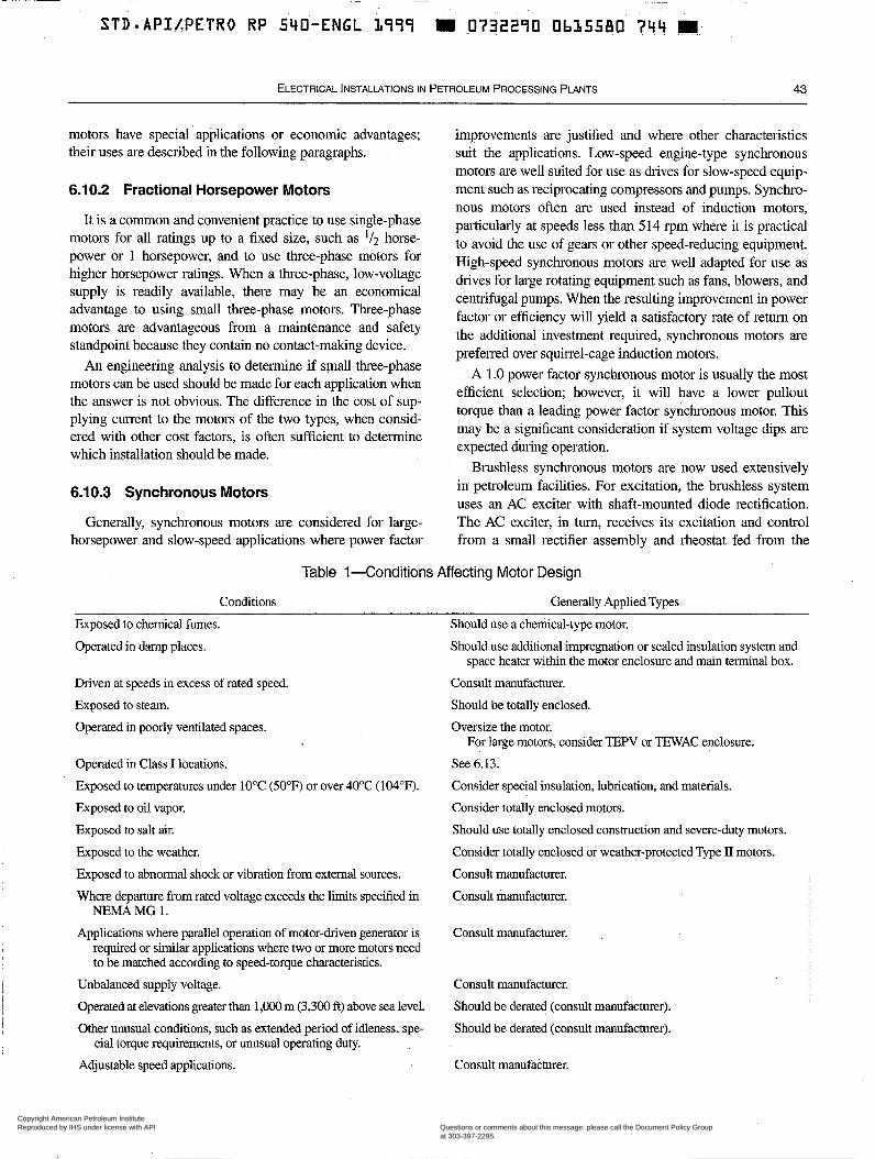
~ ~~ ~~ ~~
STD-APILPETRO RP 540-ENGL iqSS m 0732270 Ob35580 744 14
ELECTRICAL lNSTALL4TlONS IN PETROLEUM PROCESSING PLANTS 43
motors have special applications or economic advantages; their uses are described in the following paragraphs.
6.1 0.2 Fractional Horsepower Motors
It is a common and convenient practice to use single-phase motors for all ratings up to a fixed size, such as '/2 horse- power or 1 horsepower, and to use three-phase motors for higher horsepower ratings. When a three-phase, low-voltage supply is readily available, there may be an economical advantage to using small three-phase motors. Three-phase motors are advantageous from a maintenance and safety standpoint because they contain no contact-making device.
An engineering analysis to determine if small three-phase motors can be used should be made for each application when the answer is not obvious. The difference in the cost of sup- plying current to the motors of the two types, when consid- ered with other cost factors, is often sufficient to determine which installation should be made.
6.10.3 Synchronous Motors
Generally, synchronous motors are considered for large- horsepower and slow-speed applications where power factor
improvements are justified and where other characteristics suit the applications. Low-speed engine-type synchronous motors are well suited for use as drives for slow-speed equip- ment such as reciprocating compressors and pumps. Synchro- nous motors often are used instead of induction motors, par&icularly at speeds less than 514 rpm where it is practical to avoid the use of gears or other speed-reducing equipment. High-speed synchronous motors are well adapted for use as drives for large rotating equipment such as fans, blowers, and centrifugal pumps. When the resulting improvement in power factor or efficiency will yield a satisfactoly rate of return on the additional investment required, synchronous motors are prefelred over squirrel-cage induction motors.
A 1.0 power factor synchronous motor is usually the most efficient selection; however, it will have a lower pullout torque than a leading power factor synchronous motor. This may be a significant consideration if system voltage dips are expected during operation.
Brushless synchronous motors are now used extensively in' petroleum facilities. For excitation, the brushless system uses an AC exciter with shaft-mounted diode rectification. The AC exciter, in turn, receives its excitation and control from a small rectifier assembly and rheostat fed from the
Table 1-Conditions Affecting Motor Design
Conditions Generally Applied Types Exposed to chemical fumes. Operated in damp places.
Driven at speeds in excess of rated speed. Exposed to steam. Operated in poorly ventilated spaces.
Operated in Class I locations. Exposed to temperatures under 10°C (50°F) or over 40°C (104°F). Exposed to oil vapor. Exposed to salt air. Exposed to the weather. Exposed to abnormal shock or vibration from external sources. Where departure from rated voltage exceeds the limits specified in
NEMA MG 1. Applications where parallel operation of motor-driven generator is
required or similar applications where two or more motors need to be matched according to speed-torque characteristics.
i Unbalanced supply voltage. I Operated at elevations geater than 1,OOO m (3,300 ft) above sea level. I Other unusual conditions, such as extended period of idleness, spe-
cial torque requirements, or unusual operating duty. Adjustable speed applications.
Should use a chemical-type motor. Should use additional impregnation or sealed insulation system and
space heater within the motor enclosure and main terminal box. Consult manufacturer. Should be totally enclosed. Oversize the motor.
For large motors, consider TEPV or TEWAC enclosure. See 6.13. Consider special insulation, lubrication, and materials. Consider totally enclosed motors. Should use totally enclosed construction and severe-duty motors. Consider totally enclosed or weather-protected Type II motors. Consult manufacturer. Consult manufacturer.
Consult manufacturer.
Consult manufacturer. Should be derated (consult manufacturer). Should be derated (consult manufacturer).
Consult manufacturer.
Copyright American Petroleum Institute Reproduced by IHS under license with API
Document provided by IHS Licensee=BG Group/5943895100, 01/31/2005 04:58:30 MSTQuestions or comments about this message: please call the Document Policy Groupat 303-397-2295.
--`,`,,,`,`,`,,,```,,``,,`,``,,-`-`,,`,,`,`,,`---
~ 44 API RECOMMENDED PRACTICE 540
i same AC source as the motor, or from a shaft-driven perma- nent-magnet generator. There are no brushes, commutator, or collector rings; these have been the disadvantages of syn- chronous machines in the past. Since there are no arcing devices in the brushless motor, it can be used in Class I, Division 2, or Zone 2 locations.
When a synchronous motor installation is made, it is rec- ommended that the motor’s DC excitation be arranged so that it is not readily adjustable by untrained personnel, and it can be seen that the proper excitation is maintained. Otherwise, it may be found that excitation is not being maintained at a nor- mal value; with the result that the anticipated amount of power factor improvement is not being realized in actual ser- vice. Also, the performance of the motor may be adversely affected.
Unless there is a clear economic justification for prefening a synchronous motor over an induction motor (under the pre- ceding conditions), the squirrel-cage induction motor, gener- ally, would be recommended because of its greater simplicity, reliability, and maintainability.
6.10.4 Adjustable Speed Drives
The use of an adjustable speed drive and motor instead of a constant speed motor to meet process service conditions or save energy is often desirable. Typically, an adjustable-speed motor drive is one of the following types: a DC drive and motor, an adjustable-frequency AC drive and motor, or a wound-rotor motor drive.
Although the applications of adjustable-speed drives are somewhat limited, their use in today’s facilities is gaining popularity. Pump, compressor, and blower applications may allow changes in flow by speed control without utilizing con- trol valves or dampers. Elimination of conventional control valves, dampers, and gearboxes may result in added energy and investment savings; and the use of adjustable-speed drives where load varies will allow for more efficient energy utilization because these drives can be very efficient, even at reduced speeds.
6.10.4.1 DC Motor Drives
The DC motor design, one of the initial arrangements of electromechanical conversion, has existed for many years. DC motors may be used over their entire speed range, from 0% to 100% of their rated speed. Some characteristics which make DC motors desirable, besides adjustable speed use, Fe: excellent starting torque characteristics; relatively high effi- ciency throughout the speed range; and reliability.
Most DC motors are powered from AC-to-DC rectifiers, and the rectifiers are typically installed in locations that have controlled environments. These drives are available in a wide range of sizes.
Some of the ways that DC motor drives are used in petro- leum facilities are as follows:
a. Vessel agitators. b. Conveyor systems. c. Continuous mixers and extruders and pelletizers (mainly in the petrochemical industry). d. Blenders. e. Fans. f. Production drilling top drive and draw works. g. Production drilling mud pumps.
DC motor drives have some disadvantages: they require more maintenance compared to other motor types and, espe- cially in larger horsepower sizes, they are more difficult to apply in a classified location. DC motor drives using AC-to- DC rectifiers also have relatively poor power factors at low speeds, which is typical of static converter drives.
6.10.4.2 Adjustable Frequency Drives
Adjustable-frequency drives are available in sizes ranging from fractional horsepower units to units over 60,000 H P , depending on the manufacturer. Both squirrel-cage induction and synchronous motors may be used with adjustable-fre- quency drives. The AC drives typically. may operate within the range of 10% to 100% of their rated speed, with some units capable of operating in excess of their rated speed. Speeds in excess of ‘1 1,000 rpm at an output rating of 3,500 HP have been achieved. Use of the higher output rating or higher speed motors requires care in application, opera- tion, and maintenance. Some characteristics which make adjustable-frequency AC drives desirable, besides their adjustable speed, are their good starting-torque characteris- tics; their capability to provide a soft start; their high effi- ciency; their reliability; their low maintenance needs; and their no-fault contribution.
Large adjustable-frequency drives generally use a AC-to- DC rectifier coupled through a smoothing reactor to a DC-to- AC inverter. The power module enclosure for large machines requires a controlled environment and adequate clearhces for maintenance.
Among the uses of adjustable-frequency AC drives in the petroleum facilities are the following:
a. Continuous mixers, extruders, and pelletizers (mainly in the petrochemical industry). b. Vessel agitators. c. Conveyors. d. Pumps. e. Blowers. f. Compressors. g. Fans.
Some disadvantages of adjustable-frequency AC drives are their initial cost, which is higher than some other speed control
Copyright American Petroleum Institute Reproduced by IHS under license with API
Document provided by IHS Licensee=BG Group/5943895100, 01/31/2005 04:58:30 MSTQuestions or comments about this message: please call the Document Policy Groupat 303-397-2295.
--`,`,,,`,`,`,,,```,,``,,`,``,,-`-`,,`,,`,`,,`---
ELECTRICAL lNSTALLATlONS IN PETROLEUM PROCESSING PLANTS 45
systems, and their controls, which may require more space than most other drive systems. These drives also produce harmonics that, if not controlled, may cause distribution system problems, such as excessive distribution ’ system voltage distortion and overheating of the driven motor. These characteristics vary by manufacturer and dive type and should be reviewed individu- ally. Special considerations may include filtering of the dive’s output to prevent overstress of the motor winding insulation from excessive dvldt, or providing motor winding insulation capable of withstanding the additional voltage stress.
Operating duty requirements, such as efficiency, power factor, harmonics, speed range, and current in-rush, should be specified for all applications. Depending on the criticality of the application, a bypass arrangement, or a backup drive, or a drive control module should be considered.
6.1 0.4.3 Wound-Rotor Motor Drives
The wound-rotor motor is similar to the squirrel-cage induction motor except that the rotor cage winding is con- nected to a set of collector (or “slip”) rings and carbon brushes. An external adjustable resistance is connected to the collector rings, which allows the motor speed to be varied. Incremental steps are obtained through an arrangement of contractors and heavy duty (cast iron or steel) resistors. Near infinite variability is achieved with a liquid rheostat system. The wound-rotor motor drive typically operates within the 250/0-100% range of its base rated speed. As other adjustable- speed drive systems have improved, the use of wound-rotor motor drives has diminished.
Some characteristics which make the wound-rotor motor desirable are: high starting torque; reduced in-rush current; and suitability for high-inertia loads requiring closely con- trolled acceleration.
Except for the addition of the rotor circuit speed control, the starting method for the wound-rotor motor drive is similar to the starting method for the AC induction motor. The uses of the wound-rotor motor drive in petroleum facilities are rather limited, though. Some disadvantages of the wound-rotor motor drive are as follows:
a. The motor collector rings cause enclosure problems in classified areas. This motor is complicated to build because of the rotor. b. The limited speed adjustment range is generally smaller than other systems. c. The motors have lower efficiency at lower speeds due to heat dissipation of rotor current through external resistors. Slip recovery systems can be used to help improve efficiency.
6.1 1 INSTALLATION
6.1 1.1 General 1 I l leum facilities is installed outdoors without shelter from the I
Generally, electrical and mechanical equipment for petro-
weather. This applies particularly to pumps, drivers, and asso- ciated equipment which are well-suited for outdoor service. In most cases, using equipment well-suited for outdoor ser- vice saves substantial expenditures for buildings in which to house equipment. Since these buildings tend to confine and accumulate the volatile hydrocarbons released by the process equipment located within their walls and in their immediate area, outdoor installations may also simplify the problem of preventing the accumulation of such releases. Experience has shown that outdoor operation of electric motors is practical and economical with properly selected equipment.
6.1 1.2 Outdoor Service
The following types of totally enclosed motors for outdoor service are obtainable:
a. Nonexplosionproof. b. Explosionproof. c. Pipe-ventilated, either self-ventilated or forced-ventilated. d. Water-air-cooled. e. Air-to-air-cooled.
Open weather-protected motors of various designs (NEMA Type I or II) are available, with air filters as an optional acces- sory. In sizes above 250 H P , weather-protected Type II motors have gained wide acceptance. Dripproof types have been used in various applications but are not usually recommended for general outdoor use in processing plants. (NEMA MG 1, Part 1, provides a full description of enclosure types.)
6.1 1.3 Accessibility
All motors should be designed to permit ready removal of the rotor and the bearings and facilitate the flushing and relu- brication of the bearings. To facilitate inspections, adjust- ments, and repairs, all enclosed brush-type synchronous, enclosed wound-rotor, and enclosed commutating motors should have removable covers to allow ready access to the brushes, slip rings, and commutator. Eyebolts, or the equiva- lent, should be provided for lifting motors or parts weighing more than 65 kg (150 lbs).
6.12 CONSTRUCTION OFTOTALLY ENCLOSED MOTORS
External housings should completely encase totally enclosed motors. Designs in which the stator laminations form a part of the enclosure, or in which the stator laminations are otherwise exposed to the external cooling air, are not recommended.
Motor frames and enclosures preferably should be’of cast iron because motors of this construction are best suited for con- ditions where they are used outdoors or exposed to corrosive conditions. Cast iron is not always available for the very small or very large horsepower sizes. For these cases, steel of ade- quate thickness with a proper protective coating is acceptable.
Copyright American Petroleum Institute Reproduced by IHS under license with API
Document provided by IHS Licensee=BG Group/5943895100, 01/31/2005 04:58:30 MSTQuestions or comments about this message: please call the Document Policy Groupat 303-397-2295.
--`,`,,,`,`,`,,,```,,``,,`,``,,-`-`,,`,,`,`,,`---
540-ENGL $77.7
46 API RECOMMENDED PRACTICE 540
The conduit or terminal box should be of cast construction and should have a hub threaded for rigid conduit. For larger horsepower sizes, only sheet steel boxes may be available (see IEEE Std 841), particularly where auxiliary devices such as surge capacitors, lightning arresters, or differential current transformers are used.
Vertical motors should have a drip shield over the fan.
6.13 MOTORS FOR CLASS I LOCATIONS
6.13.1 Division 1 or Zone 1
6.13.1.1 Suitable Types
Motors for use in Class I, Division 1, locations, as defined in NFPA 70, should be the explosionproof type and must be suit- able for use under the specific conditions to be encountered in service. Depending on the specific conditions, a motor may have to be suitable for Class I, Groups A, B, C, or D. If a motor size is not available as explosionproof for Groups A and B, then totally enclosed pipe-ventilated motors, totally enclosed inert-gas-filled motors, or submersible-type motors must be used. For more complete details, NFPA 70 may be referenced.
An increased safety type “Ex e” motor is suitable for areas classified as Zone 1, but not for Division 1 areas. Motors are not recommended for installation in Zone O areas. This type of motor is designed to have excellent winding integrity; lim- its on internal and external temperatures during starting, oper- ation, and stalled con&tions; defined clearances between the rotating and stationary parts; and power terminals that have provisions against loosening. It is generally a TEFC motor, but can be of any totally enclosed type. An integral part of the increased safety type “Ex e” motor application is the use of a specific overload relay with the motor to limit temperatures during a stall or overload.
6.13.1.2 Nationally RecognizedTesting Laboratory (NRTL) Approval
When available, motors should bear an NRTL label of approval for the gas or vapor involved. The label shall include temperature limits or other items as required by NFF’A 70 for approved equipment.
Most laboratories cannot test larger motors, particularly those with voltage ratings exceeding 600 V. Where third-party approval is desired, the manufacturer can generally perform the tests required for conformance at the manufacturing site and submit the results to the third party for approval. Site approval may also be required and the user should work with the local “authority having jurisdiction” (see the NFPA 70) to determine the approval or labeling requirements.
6.13.1.3 Care in Inspection
The hazardous approval label becomes void when the motor enclosure is opened unless the work is performed by a
repair facility which is duly authorized (generally by the orig- inal NRTL).
6.13.2 Division 2 or Zone 2
6.13.2.1 Motors Having Arc-Making Devices
Motors for use in Class I, Division 2, locations, or in Zone 2 locations, as defined in NFPA 70, shall be the totally enclosed, explosionproof-type approved for Class I, Division 1, loca- tions when the following devices are used in the motors:
a. Sliding contacts. b. Centrifugal or other types of switching mechanisms, including motor overcurrent devices. c. Integral resistance devices, used while the motors are either starting or running.
If these devices, however, are provided with separate explo- sionproof enclosures approved for Class I locations, then motor enclosures complying with 6.13.2.2 may be utilized.
6.13.2.2 Motors Having No Arc-Making Devices
In Class I, Division 2, locations, or in Zone 2 locations, NFPA 70 permits the installation 6f squirrel-cage induction motors in enclosures other than explosionproof-type. This is permitted because it is not probable that a motor will fail elec- trically during those rare periods when gases or vapors are present in ignitable quantities.
A motor intended for use in Class I, Division 2 or Zone 2 service should be constructed so that induced currents will not produce arcing, nor produce surface temperatures capable of causing ignition of the flammable vapor.
6.1 3.3 General
6.13.3.1 Mechanical Requirements
Motors for use in a Class I area, either Division 1 or Divi- sion 2, should be nonsparking mechanically as well as electri- cally. For example, the fan or fans of a fan-cooled motor should be made of nonsparking material.
6.13.3.2 Other Factors ’
Even when other considerations may not dictate the use of totally enclosed motors, factors like dust, dirt, drifting snow, and corrosive fumes may influence the type of enclo- sure to be used.
6.13.4 Totally Enclosed Forced-Ventilated (TEFV) Motors (also known as Totally Enclosed Pipe Ventilated VEPVI)
If an application for a classified location requires a syn- chronous or wound-rotor induction motor, a motor with a Totally Enclosed Forced-Ventilated (or TEPV) enclosure may
Copyright American Petroleum Institute Reproduced by IHS under license with API
Document provided by IHS Licensee=BG Group/5943895100, 01/31/2005 04:58:30 MSTQuestions or comments about this message: please call the Document Policy Groupat 303-397-2295.
--`,`,,,`,`,`,,,```,,``,,`,``,,-`-`,,`,,`,`,,`---
ELECTRICAL INSTALLATIONS IN PETROLEUM PROCESSING PLANTS 47
be used to meet the requirements of the classified location. In some cases, the design will permit a pressurized enclosure around the collector or slip rings only; an example of this type of motor is one built with a gasketed steel metal housing.
If a motor has brushes or slip rings, it is recommended that its enclosure be provided with pressure-tight windows which permit observation of the blush or slip-ring operation. A sepa- rate source of ventilating air is provided for this type of motor, usually by a separate motor-driven blower, and the ventilating air must be drawn from a unclassified location. The air passage should also have filters to minimize the air- borne dust. A common arrangement is to interlock the blower with the main motor controller so that the blower must be started and must remain in operation for some fixed period to assure that at least ten air changes have occurred before the main motor can be started. If air ventilation is lost, interlocks are often provided to shut down the main motor.
Other interlocks are as follows:
a. An auxiliary contact to detect the opening of the ventila- tion motor controller. b. An air flow switch installed in the duct near the main motor to detect actual flow. The switch enclosure shall be suitable for the location classification.
6.13.5 Totally Enclosed Inert Gas-Filled Pressurized (TEIGF) Motors
For applications requiring a large induction or synchronous motor in a Class I, Division 1 location, a totally enclosed motor, pressurized internally with inert gas and arranged for water cooling or surface-air cooling, may be used (see NEMA MG 1 and NFPA 496). TEIGF-type of motors are rare and not readily available. In this type of application, the motor housing must be specially designed to be airtight and to provide tight closure around the shaft to prevent excessive loss of the pres- surizing medium. In the event of a pressure failure, it is required to disconnect the motor from its power source. An alarm should be provided to signal an alarm if there is any increase in temperature of the motor beyond design limits.
Nitrogen is the preferred pressurizing medium. When a motor uses nitrogen as its pressurizing medium, the oil seals should be of a type that will prevent oil from being drawn into the motor when the. motor is shut down. Where a water- cooled motor is used in this application, the cooling water should continue to flow through the motor heat exchanger when the motor is shut down.
The following accessories should be considered:
a. Indicators to show whether cooling water is flowing in the proper amount.
desired in the event of loss of pressure inside the motor, loss i b. Warning alarms or automatic shut-off devices to operate as
I
I
of the cooling water supply, water leakage from the cooler, and overheating of the stator windings or bearings. c. Other devices required to give the degree of protection warranted for the particular application.
6.13.6 Totally Enclosed Water-to-Air Cooled Motors
Totally Enclosed Water-to-Air Cooled motors use water-to- air heat exchangers. A source of cooling water or glycol- water mixture is piped to the motor heat exchanger, and the internal air is circulated over the exchanger tubes. This cooled air is then passed through the stator and rotor cores to cool the motor. The majority of the heat generated in the motor is taken up by the water supplied to it with a small portion being radiated from the frame.
Totally enclosed water-to-air-cooled motors have an advantage when medium- and large-size motors are required, and where there is an environment that is hostile to motor windings and that might otherwise require the use of NEMA Type I or Type II weather-protected motors. Totally enclosed water-to-air cooled motors, however, require protection from the possibilities of loss of cooling water or low flow. Embed- ded winding temperature detectors are usually used in this type of motor. In many cases, the motor enclosure may have a “make-up” air inlet to provide an air inlet for bearing seals. Even though the air flow rate is relatively small, this air inlet should be provided with adequate filtration.
6.14 MOTORS FOR CLASS II LOCATIONS
6.14.1 SuitableTypes
Motors for use in Class II locations, as defined in NFPA 70, shall be suitable for use in locations that are hazardous because of the presence of combustible dust.
6.14.2 Division 1
Motors should bear a third-party label of approval for Class II, Division 1, locations or be totally enclosed pipe- ventilated, meeting the temperature limitations for the spe- cific dust on them or in their vicinity. Some explosionproof motors approved for Class I, Division 1 locations are also dust ignitionproof and are approved for Class II, Division 1 locations.
6.1 4.3 Division 2
For Class II, Division 2 locations, motors should be totally enclosed nonventilated, totally enclosed pipe-venti- lated, totally enclosed fan-cooled, or totally enclosed dust- ignitionproof. The maximum full-load external temperature for these motors shall not exceed 120°C (248°F) for opera- tion in free air (not dust blanketed). Certain exceptions are permitted by NFPA 70.
Copyright American Petroleum Institute Reproduced by IHS under license with API
Document provided by IHS Licensee=BG Group/5943895100, 01/31/2005 04:58:30 MSTQuestions or comments about this message: please call the Document Policy Groupat 303-397-2295.
--`,`,,,`,`,`,,,```,,``,,`,``,,-`-`,,`,,`,`,,`---
~ 48 API RECOMMENDED PRACTICE 540
6.15 MOTOR SERVICE FACTOR
To apply a motor properly and economically, its service factor must be taken into account. A standard, integral-horse- power NEMA-frame open motor; or a high-efficiency, totally enclosed fan-cooled motor will generally have a service fac- tor of 1.15 and will carry its rated nameplate load continu- ously without exceeding its rated temperature rise. It will continuously carry 115% of its rated full load without attain- ing excessive temperature, although its insulation temperature limit will be approached, thus reducing winding insulation life. The bearings will also operate at a higher temperature, affecting bearing lubrication and bearing life. It is recom- mended that the service factor rating be reserved for contin- gency use. Consideration should also be given to the speed and torque characteristics of the motor, which are based on a 1 .O service factor.
For the above NEMA-frame and other non-NEMA-frame motors the service factor is generally 1 .O with no margin for exceedmg the naineplate rating. It is not good practice to
on such motors; therefore, it is advisable to determine defin- itive load requirements and to size motors conservatively.
As an example, a certified copy of the characteristic curve of a centrifugal pump should be examined over its entire range to determine the maximum load the curve can impose on its driver. Regardless of service, motors with a service fac- tor of 1.0 should not be operated continuously nor for extended periods at loads exceeding the nameplate rating. When heavier loading is permitted, it should be done only with the understanding that the reliability and motor life expectancy will be reduced. Additionally, other specifications may effect motor sizing, such as API Std 610.
i impose continuous loads in excess of the nameplate rating
6.16 FREQUENCY OF STARTING
" A - f r a m e motors are capable of multiple starts per hour. The number of which is defined by NEMA Std MG 1, paragraph 12.54.1, and NEMA Std MG-10 paragraph 2.8.1.
Medium voltage motors are limited in their starting capa- bility, usually to two starts from cold (or ambient) condition and one start from hot (or running temperature) condition. This is on the basis of a) the load inertia is within NEMA lim- its, b) the load start curve is a "square-of-speed" type curve, and c) the voltage at the motor terminals is greater than 90% (see 6.20). In between starts (while the motor is at rest), these units must be cooled (generally by convection) to a lower sta- tor and rotor temperature prior to another attempted start. Motors that comply with API Std 541 or Std 546 usually have greater starting capabilities. This time between starts must be coordinated with the manufacturer for automatic-restart or frequentstart duty conditions.
Note: Time between hot starts may exceed 1 hour. Motors driving high inertia loads, or operating under high power system voltage drops should receive'special consideration.
6.17 TEMPERATURE,VIBRATION, AND CURRENT INDICATORS
Motors larger than 1,000 HP and special-purpose motors frequently require temperature, current, vibration, air flow, water flow, or differential pressure monitoring. (See API Std 541 and 546 for proper application.)
6.1 8 CONDUIT OR TERMINAL BOX
Attention should be given to the size and direction of con- duit entrances to motor terminal boxes. Sizing requirements of the local electrical code should be observed. Medium and high voltage main terminal boxes may also require special construction if ANSINEMA Type II design, space for stress cone-type cable termination, or auxiliary protection devices are used.
6.19 SPACE HEATERS
6.19.1 Application
In locations where motor windings are likely to be sub- jected to accumulations of excessive moisture during extended periods of idleness, consideration should be given to the installation of space heaters or direct winding heating -"
control modules (which apply low power directly to the stator winding) to maintain the winding above the dew point. This applies, especially, to motors operating at greater than or equal to 2,300 V. Space heaters are particularly applicable to large totally enclosed motors installed outdoors and operated intermittently, and to vertical weather-protected motors, such as those used for water well service. Space heaters are also used in many large motors located indoors, particularly those that operate intermittently.. Some designs of totally enclosed fan-cooled motors are adaptable to space heater installations while others are not. Space heaters are also recommended for terminal boxes that enclose surge protection components or instrument transformers.
6.19.2 Installation Precautions
Space heaters should be selectedmd applied in a manner that prevents unsafe surface temperatures, and they should possess the correct heater rating and element temperature as well as materials that are necessary for obtaining satisfac- tory operation and long life. Generally, sheaths made of Monel or other normally corrosion-resistant .materialp should be used. The maximum sheath temperature of space heaters must be limited to 80% of the ignition temperature of the gases or vapors expected within the area unless there are special reasons for a lower limit. It is common practice to operate space heaters at half the rated voltage (or other reduced voltages), or to specify low-surface temperature [e.g.. 200°C (392'F)I to prevent excessive temperatures and
Copyright American Petroleum Institute Reproduced by IHS under license with API
Document provided by IHS Licensee=BG Group/5943895100, 01/31/2005 04:58:30 MSTQuestions or comments about this message: please call the Document Policy Groupat 303-397-2295.
--`,`,,,`,`,`,,,```,,``,,`,``,,-`-`,,`,,`,`,,`---
STDmAPI/PETRO RP 540-ENGL 1999 1111 0732290 0b3558b. 1 b . Z E.;
ELECTRICAL INSTALLATIONS IN PETROLEUM PROCESSING PLANTS 49
to increase heater life. Space heater leads are often wired out to a separate terminal box.
6.19.3 Ratings
Space heaters usually have an operating voltage rating of 115 V or 230 V, single phase. Heating capacity should be sized to maintain the winding temperature 5°C to 10°C (10°F to 20°F) above ambient temperature.
6.1 9.4 Operation
When auxilia7 contacts are used in the motor starter, the supply circuit to the motor heater is normally arranged to be de-energized automatically when the motor is started, and energized when the motor is stopped. If used, terminal box heaters are normally continuously energized or controlled by differential temperature thermostats. A local nameplate at or near the space heater auxiliary terminal box or connection point should indicate when a separately derived power source is employed.
6.19.5 Low-Voltage Winding Heating
Low-voltage winding heating is a method for heating a motor winding while the motor is shut down. This heating is accomplished by applying low voltage directly to one phase of the motor winding. The amount of heating voltage neces- sary to circulate the proper current in the winding and keep the internal temperature 5°C to 10°C (10°F to 20°F) above ambient must be selected. Approximately 5% voltage is nor- mally sufficient to maintain this temperature. A low-voltage contactor must be interlocked with the main contactor to keep the two sources of power electrically separated. Low-voltage winding heating is normally used for small motors because it is usually more economical to use space heaters for motors over 100 HP.
6.20 BEARINGS AND LUBRICATION
6.20.1 Horizontal Motors
Motors are available with either antifriction (ball or roller) or hydrodynamic radial (sleeve) bearings. The type of bearing lubrication, whether oil, oil mist, or grease, should be chosen when the bearings are selected. Most NEMA-kame and IEEE-841 motors will have grease-lubricated antifriction bearings. Motors above NEMA standard sizes should be designed according to API Stds 541 and 546.
Most sleeve bearings for horizontal motors are oil-lubri- cated using oil rings. Except where a forced-oil lubrication system is used, the bearings should be equipped with con- stant-visible-level automatic oilers. Wick or yarn oilers are
motor sizes. I not satisfactory except for the smallest fractional horsepower
~
I ~~
An opening should be provided to permit observation of the oil rings if the motor is in operation. Suitable slingers, pressure equalizers, and vents are required to prevent loss of lubricant and to maintain the proper level.
For large (1,000 HF'), sleeve-bearing motors, particularly those used to drive equipment that requires forced-oil lubrica- tion, consideration should also be given to using forced-oil lubrication for the motors. API Std 614 covers lubrication systems for special drive trains.
Sleeve-bearing motors, usually in the larger sizes, require the use of limited-end-float couplings to keep the motor rotors centered. When the couplings are properly installed, the motors will operate at or near their magnetic center.
Ball bearings for horizontal motors are usually grease- lubricated, except in the larger sizes and in horizontal motors that operate at higher speeds. Horizontal motors operating at higher speeds often use oil-lubricated ball or roller bearings.
Some manufacturers provide grease-lubricated ball-bear- ing motors with sealed bearings that permit several years of operation without regreasing. At the end of these periods, the bearings are either repacked or replaced. Because many bear- ing failures are the result of too-frequent greasing, overgreas- ing, or mixing of incompatible greases, motors which permit long periods between regreasings are the most desirable, par- ticularly in plants that lack suitable maintenance personnel and control over their regreasing programs.
When oil mist lubrication is used, internal and noncontact- ing external shaft seals should be used. The seal and main lead insulation material shall be compatible with the oil.
6.20.2 Vertical Motors
The thrust bearings in vertical motors include antifriction (ball or roller) and plate-type thrust bearings. When oil is used as the lubricant for either thrust or guide bearings, the oil reservoir should be deep enough to serve as a settling cham- ber for foreign matter; should be provided with drain plugs accessible from outside the motor housings; and, except where a forced-oil type of lubrication system is used, should be equipped with constant-visible-level automatic oilers. In vertical motors, it is generally preferred that all bearings use the same type of lubricant. The magnitude and direction of external thrust, operating speed, and required bearing life will determine the type of bearing used.
Where required, it is common practice to supply motors that are subject to high thrust, equipped with bearings that are capable of carrying thrusts from driven equipment. The motors on vertical pumps are examples of motors equipped with bear- ings capable of carrying the high thrusts from the pump. When high-thrust driven equipment is being used, it is essential to specify the max imu thrust loads in both directions. (For ver- tical motor bearing requirements, see A P I Std 610.)
Copyright American Petroleum Institute Reproduced by IHS under license with API
Document provided by IHS Licensee=BG Group/5943895100, 01/31/2005 04:58:30 MSTQuestions or comments about this message: please call the Document Policy Groupat 303-397-2295.
--`,`,,,`,`,`,,,```,,``,,`,``,,-`-`,,`,,`,`,,`---
STD APIJPETRO,. RP ..S.GO-.ENGL, IRVI
50 API RECOMMENDED PRACTICE 540
6.21 TORQUE REQUIREMENTS
6.21.1 Torque Considerations
Most motors used in petroleum processing and associated operations drive centrifugal or rotary pumps, centrifugal blowers, centrifugal compressors, and other equipment that do not impose unusually difficult torque requirements. Nor- mal-torque motors are well-adapted to such equipment and usually will have sufficient torque to meet the normal condi- tions of service, provided the supply voltages are satisfac- tory. The net torque delivered by the motors to the driven equipment is less than the rated torque of the motors when the voltages at the terminals of the motors are less than the rated voltages of the motors. Table 2 shows characteristic torque variations of large squirrel-cage induction motors and synchronous motors, with respect to applied voltage.
For example, a motor capable of exerting a locked-rotor (or starting) torque of 100% (with respect to full-load running torque) with its nameplate voltage at its terminals may be found to have only 90% of its nameplate voltage at its termi- nals at the instant it is started across the line, due to a 10% voltage drop during this period of high current in-rush. The output torque developed by the motor is proportional to the terminal voltage squared times the full voltage locked-rotor torque; or, under a 10% voltage-drop condition, this is calcu- .lated to be: 0.9 x 0.9 x 100, or 81%.
Similarly, the entire starting torque curve is reduced by the same value. From NEMA MG 1 paragraph 20.41, a medium voltage induction motor minimum torque curve is 60% locked rotor; 60% pull-up; and 175% breakdown torque (under full voltage condition). Under a 20% voltage drop, this curve then becomes 38% / 38% / 112%. (See Figure 14.) Additionally, any further reductions in voltage due to line loss or auto-transformers will be added to the system drop. This figure also includes the typical "square-of-speed" type curve for centrifugal loads. The top line is for open valve or damper- type starting, while the lower line is for throttled- type starting (this example is for a 50% closed valve/damper start). It can be seen from this example that the effect of reducing the voltage at the motor terminals may prevent start- up unless the load-starting curve can be reduced.
6.21.2 Torque Analysis
The maximum torque that can be developed by a motor is proportional to the square of the voltage, resulting in acceler- ation torque reduction for reduced-system voltage. Power system, motor, and load characteristics should be evaluated to assure adequate torque during starting and acceleration. It should also be evaluated during re-acceleration and re-syn- chronizing following voltage sags and disturbances.
However, if the inspection of the available data does not yield a clear result, it is recommended that a detailed engi- neering analysis be performed to resolve marginal cases and
Table 2-Characteristic Torques
Squirrel-Cage Induction Motors Synchronous Motors ~
Locked-rotor torquea 60% Locked-rotor torquea 40%
Pull-up torquea 60% Pull-in torquea 30%
Breakdown torquea 175% Pull-out torquebJ 150%
aThe output torque varies approximately as the square of applied voltage. bThe output torque varies directly as the applied voltage. cWith excitation constant.
to avoid any delays or inconveniences that may be caused by the failure of motor-driven equipment to start satisfactorily.
If reduced-voltage reactor or resistor starting is used, a sub- stantial amount of impedance is introduced into the supply circuit of the motor when the controller is in the starting posi- ti,on. This impedance as well as the other impedance between the motor and its supply source must be taken into account. All reduced-voltage starting applications should evaluate the starting torque available versus that required by the load (acceleration torque) to determine that adequate torque mar- gin is available for starting the load.
A torsional analysis should be undertaken for high-speed synchronous motors to determine the effects of torsional pul- sations during across-the-line start acceleration of the motor and driven equipment.
6.21.3 Low-Voltage Considerations
Voltage that is lower than normal may exist, particularly dur- ing starting, because of the system's design or characteristics. Some causes for this lower-than-normal voltage are as follows:
a. The motor being started is large in relation to the capacity of the electrical supply system. b. The supply circuit's length and design cause an unduly high voltage drop between the power source and motor.
Where it is questionable whether the voltage received at the terminals of the motor will be satisfactory, the voltage at that point should be calculated under the most unfavorable conditions likely to exist in actual service. In most cases, this will be at the instant of starting, when the current inrush is several times the rated full-load current and the power factor is low, usually in the 0.2 to 0.4 range. If the circuit under con- sideration will be used to carry other loads, the effect of these other loads on voltage should be taken into account at the same time.
When a synchronous motor is to be used, voltage condi- tions at the instant of pull-in should be checked. It must be determined that correct torque will be developed at the pull-in point with net voltage available at the motor terminals.
Copyright American Petroleum Institute Reproduced by IHS under license with API
Document provided by IHS Licensee=BG Group/5943895100, 01/31/2005 04:58:30 MSTQuestions or comments about this message: please call the Document Policy Groupat 303-397-2295.
--`,`,,,`,`,`,,,```,,``,,`,``,,-`-`,,`,,`,`,,`---
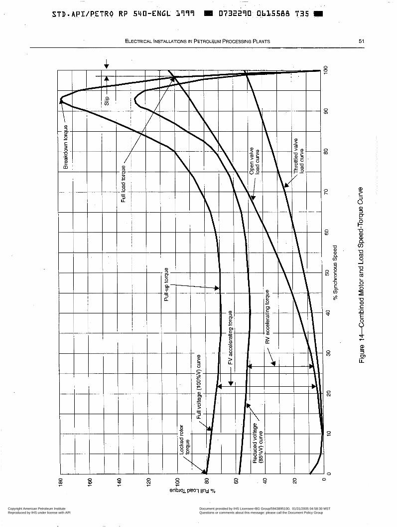
STD.API/PETRO R P 540-ENGL ,1999 M 0732290 Ob15588 T35
ELECTRICAL INSTALLATIONS IN PETROLEUM PROCESSING PLANTS 51
O e O (D 7
S 7
O (D S O
N O
3 2
3
3
O N
O 7
O
Copyright American Petroleum Institute Reproduced by IHS under license with API
Document provided by IHS Licensee=BG Group/5943895100, 01/31/2005 04:58:30 MSTQuestions or comments about this message: please call the Document Policy Groupat 303-397-2295.
--`,`,,,`,`,`,,,```,,``,,`,``,,-`-`,,`,,`,`,,`---
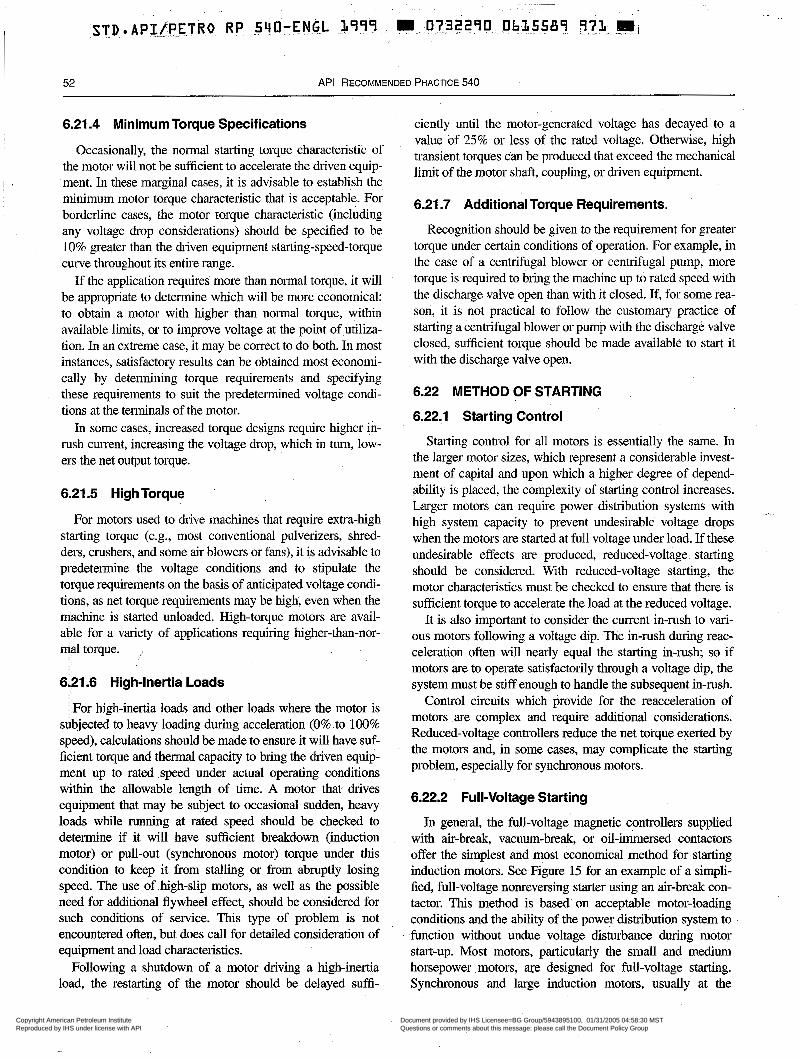
52 API RECOMMENDED PRACTICE 540
I 6.21 -4 Minimum Torque Specifications
Occasionally, the normal starting torque characteristic of the motor will not be sufficient to accelerate the driven equip-
minimum motor torque characteristic that is acceptable. For borderline cases, the motor torque characteristic (including any voltage drop considerations) should be specified to be 10% greater than the driven equipment starting-speed-torque curve throughout its entire range.
If the application requires more than normal torque, it will be appropriate to determine which will be more economical: to obtain a motor with higher than normal torque, within available limits, or to improve voltage at the point of utiliza- tion. In an extreme case, it may be correct to do both. In most instances, satisfactory results can be obtained most economi- cally by determining torque requirements and specifying these requirements to suit the predetermined voltage condi- tions at the terminals of the motor.
In some cases, increased torque designs require higher in- rush current, increasing the voltage drop, which in turn, low- ers the net output torque.
6.21.5 High Torque
I , ment. In these marginal cases, it is advisable to establish the
For motors used to drive machines that require extra-high starting torque (e.g., most conventional pulverizers, shred- ders, cmshers, and some air blowers or fans), it is advisable to predetermine the voltage conditions and to stipulate the torque requirements on the basis of anticipated voltage condi- tions, as net torque requirements may be high, even when the machine is started unloaded. High-torque motors are avail- able for a variety of applications requiring higher-than-nor- mal torque. i
6.21.6 High-Inertia Loads
For high-inertia loads and other loads where the motor is subjected to heavy loading during acceleration (0% to 100% speed), calculations should be made to ensure it will have suf- ficient torque and thermal capacity to bring the driven equip- ment up to rated speed under actual operating conditions within the allowable length of time. A motor that drives equipment that may be subject to occasional sudden, heavy loads while running at rated speed should be checked to determine if it will have sufficient breakdown (induction motor) or pull-out (synchronous motor) torque under this condition to keep it from stalling or from abruptly losing speed. The use of high-slip motors, as well as the possible need for additional flywheel effect, should be considered for such conditions of service. This type of problem is not encountered often, but does call for detailed consideration of equipment and load characteristics.
Following a shutdown of a motor driving a high-inertia load, the restarting of the motor should be delayed suffi-
ciently until the motor-generated voltage has decayed to a value of 25% or less of the rated voltage. Otherwise, high transient torques can be produced that exceed the mechanical limit of the motor shaft, coupling, or driven equipment.
6.21.7 Additional Torque Requirements.
Recognition should be given to the requirement for greater torque under certain conditions of operation. For example, in the case of a centrifugal blower or centrifugal pump, more torque is required to bring the machine up to rated speed with the discharge valve open than with it closed. If, for some rea- son, it is not practical to follow the customary practice of starting a centrifugal blower or pump with the discharge valve closed, sufficient torque should be made available to start it with the discharge valve open.
6.22 METHOD OF STARTING
6.22.1 Starting Control
Starting control for all motors is essentially the same. In the larger motor sizes, which represent a considerable invest- ment of capital and upon which a higher degree of depend- ability is placed, the complexity of starting control increases. Larger motors can require power distribution systems with high system capacity to prevent undesirable voltage drops when the motors are started at full voltage under load. If these undesirable effects are produced, reduced-voltage. starting should be considered. With reduced-voltage starting, the motor characteristics must be checked to ensure that there is sufficient torque to accelerate the load at the reduced voltage.
It is also important to consider the current in-rush to vari- ous motors following a voltage dip. The in-rush during reac- celeration often will nearly equal the starting in-rush; so if motors are to operate satisfactorily through a voltage dip, the system must be stiff enough to handle the subsequent in-rush.
Control circuits which provide for the reacceleration of motors are complex and require additional considerations. Reduced-voltage controllers reduce the net torque exerted by the motors and, in some cases, may complicate the starting problem, especially for synchronous motors.
6.22.2 Full-Voltage Starting
In general, the full-voltage magnetic controllers supplied with air-break, vacuum-break, or oil-immersed contactors offer the simplest and most economical method for starting induction motors. See Figure 15 for an example of a simpli- fied, full-voltage nonreversing starter using an air-break con- tactor. This method is based on acceptable motor-loading conditions and the ability of the power distribution system to function without undue voltage disturbance during motor start-up. Most motors, particularly the small and medium horsepower motors, we designed for full-voltage starting. Synchronous and large induction motors, usually at the
Copyright American Petroleum Institute Reproduced by IHS under license with API
Document provided by IHS Licensee=BG Group/5943895100, 01/31/2005 04:58:30 MSTQuestions or comments about this message: please call the Document Policy Groupat 303-397-2295.
--`,`,,,`,`,`,,,```,,``,,`,``,,-`-`,,`,,`,`,,`---
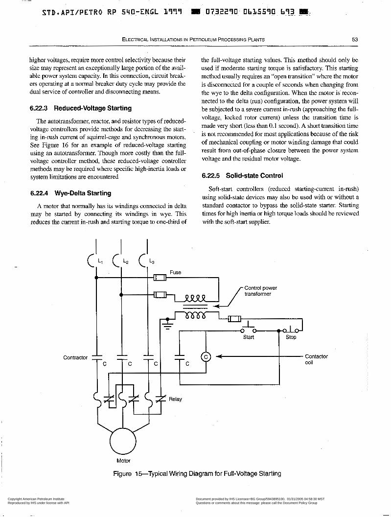
ELECTRICAL INSTALLATIONS I N PETROLEUM PROCESSING PLANTS 53
higher voltages, require more control selectivity because their size may represent an exceptionally large portion of the avail- able power system capacity. In this connection, circuit break- ers operating at a normal breaker duty cycle may provide the dual service of controller and disconnecting means.
6.22.3 Reduced-Voltage Starting
The autotransformer, reactor, and resistor types of reduced- voltage controllers provide methods for decreasing the start- ing in-rush current of squin-el-cage and synchronous motors. See Figure 16 for an example of reduced-voltage starting using an autotransformer. Though more costly than the full- voltage controller method, these reduced-voltage controller methods may be required where specific high-inertia loads or system limitations are encountered
6.22.4 Wye-Delta Starting
A motor that normally has its windings connected in delta may be started by connecting its windings in wye. This reduces the current in-rush and starting torque to one-third of
the full-voltage starting values. This method should only be used if moderate starting torque is satisfactory. This starting method usually requires an "open transition" where the motor is disconnected for a couple of seconds when changing from the wye to the delta configuration. When the motor is recon- nected to the delta (run) configuration, the power system will be subjected to a severe current in-lush (approaching the full- voltage, locked rotor current) unless the transition time is made very short (less than 0.1 second). A short transition time is not recommended for most applications because of the risk of mechanical coupling or motor winding damage that could result from out-of-phase closure between the power system voltage and the residual motor voltage.
6.22.5 Solid-state Control
Soft-start controllers (reduced starting-current in-rush) using solid-state devices may also be used with or without a standard contactor to bypass the solid-state starter. Starting times for high inertia or high torque loads should be reviewed with the soft-start supplier.
Contractor
Fuse t"",
d l -1 -1 - - -
Control power transformer
Start Stop
" "
" " "
C C C C
Motor
Contactor coil
I Figure 15-Typical Wiring Diagram for Full-Voltage Starting
Copyright American Petroleum Institute Reproduced by IHS under license with API
Document provided by IHS Licensee=BG Group/5943895100, 01/31/2005 04:58:30 MSTQuestions or comments about this message: please call the Document Policy Groupat 303-397-2295.
--`,`,,,`,`,`,,,```,,``,,`,``,,-`-`,,`,,`,`,,`---
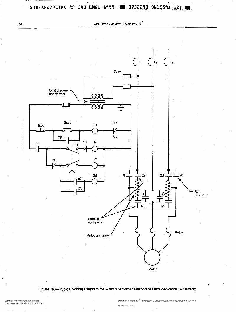
54 API RECOMMENDED PRACTICE 540
Control power transformer
I I ' T
I
Autotransformer
Motor
L3
1
Run contactor
Figure 16-Typical Wiring Diagram for Autotransformer Method of Reduced-Voltage Starting
Copyright American Petroleum Institute Reproduced by IHS under license with API
Document provided by IHS Licensee=BG Group/5943895100, 01/31/2005 04:58:30 MSTQuestions or comments about this message: please call the Document Policy Groupat 303-397-2295.
--`,`,,,`,`,`,,,```,,``,,`,``,,-`-`,,`,,`,`,,`---
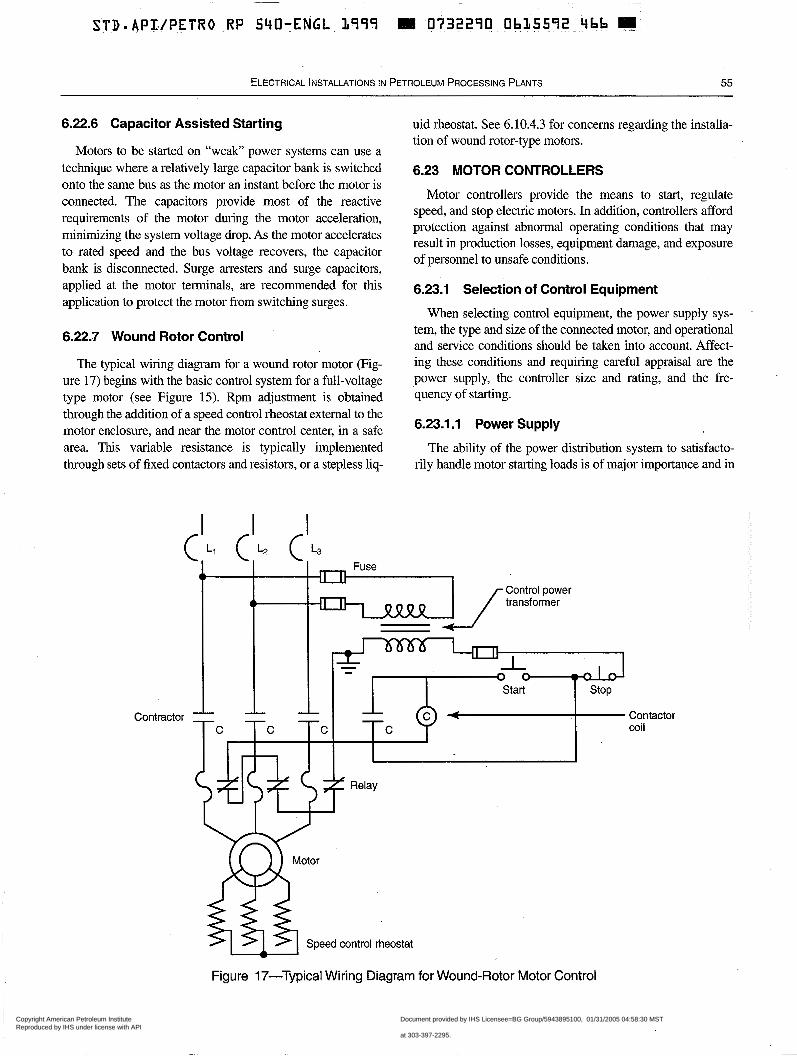
STD.API . /PETRO.RP 540-ENGL 1799 M 0732290 Ob15572 466 3
ELECTRICAL INSTALLATIONS IN PETROLEUM PROCESSING PLANTS 55
6.22.6 Capacitor Assisted Starting
Motors to be started on “weak” power systems can use a technique where a relatively large capacitor bank is switched onto the same bus as the motor an instant before the motor is connected. The capacitors provide most of the reactive requirements of the motor during the motor acceleration, minimizing the system voltage drop. As the motor accelerates to rated speed and the bus voltage recovers, the capacitor bank is disconnected. Surge arresters and surge capacitors, applied at the motor terminals, are recommended for this application to protect the motor from switching surges.
6.22.7 Wound Rotor Control
The typical wiring diagram for a wound rotor motor (Fig- ure 17) begins with the basic control system for a full-voltage type motor (see Figure 15). Rpm adjustment is obtained through the addition of a speed control rheostat external to the motor enclosure, and near the motor control center, in a safe area. This variable resistance is typically implemented through sets of fixed contactors and resistors, or a stepless liq-
uid rheostat. See 6.10.4.3 for concerns regarding the installa- tion of wound rotor-type motors.
6.23 MOTOR CONTROLLERS
Motor controllers provide the means to start, regulate speed, and stop electric motors. In addition, controllers afford protection against abnormal operating conditions that may result in production losses, equipment damage, and exposure of personnel to unsafe conditions.
6.23.1 Selection of Control Equipment
When selecting control equipment, the power supply sys- tem, the type and size of the connected motor, and operational and service conditions should be taken into account. Affect- ing these conditions and requiring careful appraisal are the power supply, the controller size and rating, and the fre- quency of starting.
6.23.1 .I Power Supply
The ability of the power distribution system to satisfacto- rily handle motor starting loads is of major impor&ance and in
Contra
L. L . L.
4- Control power transformer
ctor i l
W Motor m Speed control rheostat
Contactor mil
Figure 17-Typical Wiring Diagram for Wound-Rotor Motor Control
Copyright American Petroleum Institute Reproduced by IHS under license with API
Document provided by IHS Licensee=BG Group/5943895100, 01/31/2005 04:58:30 MSTQuestions or comments about this message: please call the Document Policy Groupat 303-397-2295.
--`,`,,,`,`,`,,,```,,``,,`,``,,-`-`,,`,,`,`,,`---
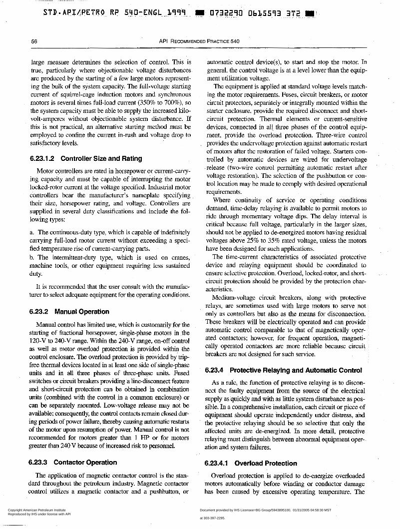
56 API RECOMMENDED PRACTICE 540
large measure determines the selection of control. This is true, particularly where objectionable voltage disturbances are produced by the starting of a few large motors represent- ing the bulk of the system capacity. The full-voltage starting current of squirrel-cage induction motors and synchronous motors is several times full-load current (350% to 700%), so the system capacity must be able to supply the increased kilo- volt-amperes without objectionable system disturbance. If this is not practical, an alternative starting method must be employed to confine the current in-rush and voltage drop to satisfactory levels.
6.23.1.2 Controller Size and Rating
Motor controllers are rated in horsepower or current-carry- ing capacity and must be capable of interrupting the motor locked-rotor current at the voltage specified. Industrial motor controllers bear the manufacturer’s nameplate specifying their size, horsepower rating, and voltage. Controllers are supplied in several duty classifications and include the fol- lowing types:
a. The continuous-duty type, which is capable of indefinitely carrying full-load motor current without exceeding a speci- fied temperature rise of current-carrying parts. b. The intermittent-duty type, which is used on cranes, machine tools, or other equipment requiring less sustained duty.
It is recommended that the user consult with the manufac- turer to select adequate equipment for the operating conditions.
6.23.2 Manual Operation
Manual control has limited use, which is customarily for the starting of fractional horsepower, single-phase motors in the 120-V to 240-V range. Within the 240-V range, on-off control as well as motor overload protection is provided within the control enclosure. The overload protection is provided by trip- free thermal devices located in at least one side of single-phase units and in all three phases of three-phase units. Fused switches or circuit breakers providing a line-disconnect feature and short-circuit protection can be obtained in combination units (combined with the control in a common enclosure) or can be separately mounted. Low-voltage release may not be available; consequently, the control contacts remain closed dur- ing periods of power failure, thereby causing automatic restarts of the motor upon resumption of power. Manual control is not recommended for motors greater than 1 HP or for motors greater than 240 V because of increased risk to personnel.
6.23.3 Contactor Operation
The application of magnetic contactor control is the stan- dard throughout the petroleum industry. Magnetic contactor control utilizes a magnetic contactor and a pushbutton, or
automatic control device(s), to start and stop the motor. In general, the control voltage is at a level lower than the equip- ment utilization voltage.
The equipment is applied at standard voltage levels match- ing the motor requirements. Fuses, circuit breakers, or motor circuit protectors, separately or integrally mounted within the starter enclosure, provide the required disconnect and short- circuit protection. Thermal elements or current-sensitive devices, connected in all three phases of the control equip- ment, provide the overload protection. Three-wire control provides the undervoltage protection against automatic restart of motors after the restoration of failed voltage. Starters con- trolled by automatic devices are wired for undervoltage release (two-wire control permitting automatic restart after voltage restoration). The selection of the pushbutton or con- trol location may be made to comply with desired operational requirements.
Where continuity of service or operating conditions demand, time-delay relaying is available to permit motors to ride through momentary voltage dips. The delay interval is critical because full voltage, particularly in the larger sizes, should not be applied to de-energized motors having residual voltages above 25% to 35% rated voltage, unless the motors have been designed for such applications.
The time-current characteristics of associated protective device and relaying equipment should be coordinated to ensure selective protection. Overload, locked-rotor, and short- circuit protection should be provided by the protection char- acteristics.
Medium-voltage circuit breakers, along with protective relays, are sometimes used with large motors to serve not only as controllers but also as the means for disconnection. These breakers will be electrically operated and can provide automatic control comparable to that of magnetically oper- ated contactors; however, for frequent operation, magneti- cally operated contactors are more reliable because circuit breakers are not designed for such service.
6.23.4 Protective Relaying and Aútomatic Control
As a rule, the function of protective relaying is to discon- nect the faulty equipment from the source of the electrical supply as quickly and with as little system disturbance as pos- sible. In a comprehensive installation, each circuit or piece of equipment should operate independently under distress, ~d the protective relaying should be so selective that only the affected units are de-energized. In more detail, protective relaying must distinguish between abnormal equipment oper- ation and system failures.
6.23.4.1 Overload Protection
Overload protection is applied to de-energize overloaded motors automatically before winding or conductor damage has been caused by excessive operating temperature. The
Copyright American Petroleum Institute Reproduced by IHS under license with API
Document provided by IHS Licensee=BG Group/5943895100, 01/31/2005 04:58:30 MSTQuestions or comments about this message: please call the Document Policy Groupat 303-397-2295.
--`,`,,,`,`,`,,,```,,``,,`,``,,-`-`,,`,,`,`,,`---
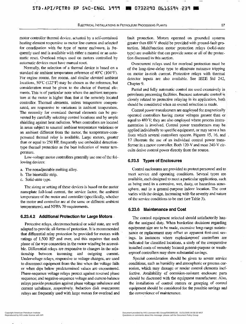
~
STD=API/PETRO RP 540-ENGL 1799 111 0732290 OhL5594..239. m
ELECTRICAL INSTALLATIONS IN PETROLEUM PROCESSING PLANTS 57
motor controller thermal device, actuated by a self-contained heating element responsive to motor line current and selected for coordination with the type of motor enclosure, is fre- quently used and is available with either a manual or an auto- matic reset. Overload relays used on motors controlled by automatic devices must have manual reset.
Noimally, the selection of a thermal device is based on a standard air ambient temperature reference of 40°C (104°F). For engine rooms, fire rooms, and similar elevated ambient locations, 50°C (122°F) may be chosen as the reference, but consideration must be given to the choice of thermal ele- ments. This is of particular note where the ambient tempera- ture at the motor is higher than that at the remotely located controller. Thermal elements, unless temperature compen- sated, are responsive to variations in ambient temperature. The necessity for oversized thelmal elements can be pre- vented by carefully selecting control locations and by ample shielding against heat radiation. When controllers are located in areas subject to unusual ambient temperature variations or an ambient different from the motor, the temperature-com- pensated thermal relay is available. Large motors, greater than or equal to 250 H€', frequently use embedded detection- type thermal protection as the best indication of motor tem- perature.
Low-voltage motor controllers generally use one of the fol- lowing devices:
a. The nonadjustable melting alloy. b. The bimetallic strip. c. Solid-state type.
The sizing or setting of these devices is based on the motor nameplate full-load current, the service factor, the ambient temperature of the motor and controller (specifically, whether the motor and controller are at the same or different ambient temperatures), and NFPA 70 requirements.
6.23.4.2 Additional Protection for Large Motors
Protective relays, electromechanical or solid state, are well adapted to provide all forms of protection. It is recommended that differential relay protection be provided for motors with ratings of 1,500 HP and over, and this requires that each phase of the wye connection in the motor winding be accessi- ble. Differential relays are responsive to changes in the rela- tionship between incoming and outgoing current. Undervoltage relays, responsive to voltage changes, are used to disconnect equipment from the line when the voltage fails or when dips below predetermined values are encountered. Phase-sequence voltage relays protect against reversed phase sequence; and negative-sequence voltage and current-balance relays provide protection against phase voltage unbalance and current unbalance, respectively. lnduction disk overcurrent relays are frequently used with large motors for overload and
fault protection. Motors operated on grounded systems greater than 600 V should be provided with ground-fault pro- tection. Multifunction motor protection relays (solid-state type) are available that can provide some or all of the protec- tion discussed in this section.
Overcurrent relays used for overload protection must be of the long-time-delay type to eliminate nuisance tripping on motor in-rush current. Protective relays with thermal detector inputs are also available. See IEEE Std 242, Chapter 9.
Partial and fully automatic control are used extensively in petroleum processing facilities. Because automatic control is closely related to protective relaying in its application, both should be considered when an overall selection is made.
Control power transformers are employed for magnetically operated controllers having motor voltages greater than or equal to 480 V; they are also employed where process instru- mentation is involved. Control power transformers may be applied individually to specific equipment, or may serve a bus from which several controllers operate. Figures 15, 16, and 17 illustrate the use of an individual control power trans- former in a motor controller. Both 120-V and most 240-V cir- cuits derive control power directly from the source.
6.23.5 Types of Enclosures
Control enclosures are provided to protect personnel and to meet service and operating conditions. Several types are available, each designed to meet a particular application, such as being used in a corrosive, wet, dusty, or hazardous atmo- sphere, and in a general-purpose indoor location. The cost varies with the design, increasing with the severity and nature of the service conditions to be met (see Table 3).
6.23.6 Maintenance and Cost
The control equipment selected should satisfactorily han- dle the assigned duty. When borderline decisions regarding equipment size are to be made, excessive long-range mainte- nance or replacement may offset an apparent first-cost sav- ings. In instances where explosionproof controllers are indicated for classified locations, a study of the comparative installed costs of remotely located general-purpose or weath- erproof controllers may show substantial savings.
Special consideration should be given to severe service conditions, such as humidity and atmospheric or process cor- rosion, which may damage or render control elements inef- fective. Availability of corrosion-resistant enclosure parts should be discussed with the equipment manufacturer. Also, the installation of control centers or grouping of control equipment should be considered for the possible savings and the convenience of maintenance.
Copyright American Petroleum Institute Reproduced by IHS under license with API
Document provided by IHS Licensee=BG Group/5943895100, 01/31/2005 04:58:30 MSTQuestions or comments about this message: please call the Document Policy Groupat 303-397-2295.
--`,`,,,`,`,`,,,```,,``,,`,``,,-`-`,,`,,`,`,,`---
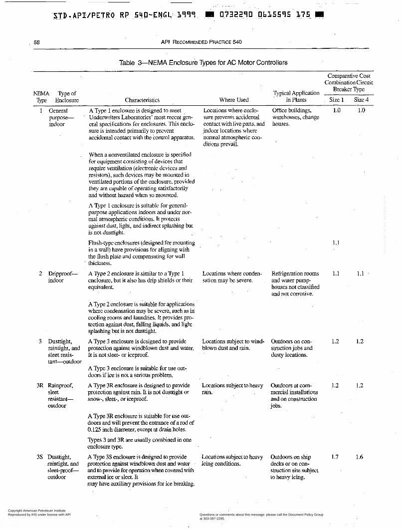
58 API RECOMMENDED PRACTICE 540
Table 3-NEMA Enclosure Types for AC Motor Controllers
Comparative Cost Combination Circuit
NEMA Typeof Type Enclosure Characteristics
1 General A Type 1 enclosure is designed to meet purpose- ' Underwriters Laboratories' most recent gen- indoor eral specifications for enclosures. This enclo-
sure is intended primarily to prevent accidental contact with the control apparatus.
2 Dripproof- indoor
3 Dusttight, raintight, and sleet resis- tant-outdoor
3R Rainproof, sleet resistant- outdoor
3 s Dusttight, raintight, and
outdoor sleet-proof-
When a nonventilated enclosure is specified for equipment consisting of devices that require ventilation (electronic devices and resistors), such devices may be mounted in ventilated portions of the enclosure, provided they are capable of operating satisfactorily and without hazard when so mounted.
A Type 1 enclosure is suitable for general- purpose applications indoors and under nor- mal atmospheric conditions. It protects against dust, light, and indirect splashing but is not dusttight.
Flush-type enclosures (designed for mounting in a wall) have provisions for aligning with the flush plate and compensating for wall thickness.
A Type 2 enclosure is similar to a Type 1 enclosure, but it also has drip shields or their equivalent.
A Type 2 enclosure is suitable for applications where condensation may be severe, such as in cooling rooms and laundries. It provides pro- tection against dust, falling liquids, and light splashing but is not dusttight.
A Type 3 enclosure is designed to provide protection against windblown dust and water. It is not sleet- or iceproof.
A Type 3 enclosure is suitable for use out- doors if ice is not a serious problem.
A Type 3R enclosure is designed to provide protection against rain. It is not dusttight or snow-, sleet-, or iceproof.
A Type 3R enclosure is suitable for use out- doors and will prevent the entrance of a rod of 0.125 inch diameter, except at drain holes.
Types 3 and 3R are usually combined in one enclosure type.
A Type 3 s enclosure is designed to provide protection against windblown dust and water and to provide for operation when covered with external ice or sleet. It may have auxiliary provisions for ice breaking.
Typical Application Breaker Type
Where Used in Plants Size 1 Size 4
Locations where enclo- Office buildings, 1 .o 1 .D sure prevents accidental warehouses, change contact with live parts, and houses. indoor locations where normal atmospheric con- ditions prevail.
Locations where conden- sation may be severe.
Locations subject to wind- blown dust and rain.
Locations subject to heavy rain.
Locations subject to heavy icing conditions.
Refrigeration rooms and water pump- houses not classified and not corrosive.
Outdoors on con- struction jobs and dusty locations.
Outdoors at com- mercial installations and on construction jobs.
Outdoors on ship decks or on con- struction site subject to heavy icing.
1.1
1.1 1.1
1.2 1.2
1.2 1.2
1.7 1.6
Copyright American Petroleum Institute Reproduced by IHS under license with API
Document provided by IHS Licensee=BG Group/5943895100, 01/31/2005 04:58:30 MSTQuestions or comments about this message: please call the Document Policy Groupat 303-397-2295.
--`,`,,,`,`,`,,,```,,``,,`,``,,-`-`,,`,,`,`,,`---
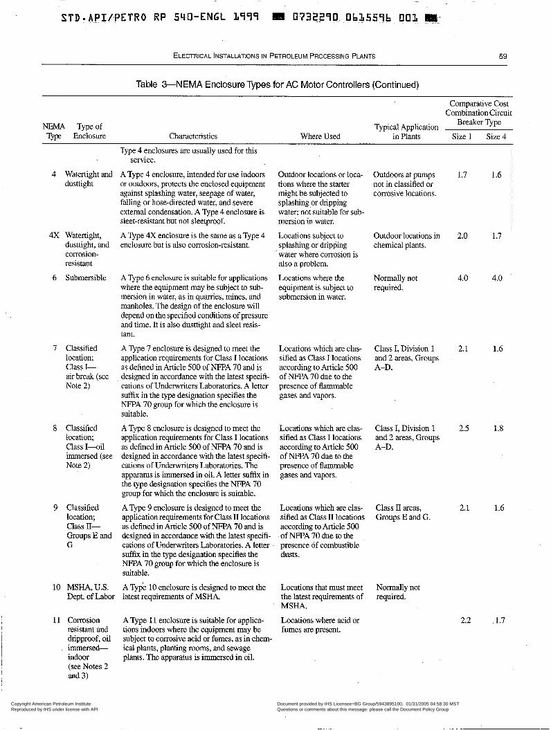
ELECTRICAL INSTALLATIONS IN PETROLEUM PROCESSING PLANTS 59
Table 3-NEMA Enclosure Types for AC Motor Controllers (Continued)
NEMA Type of T p Enclosure Characteristics
Typical Application Where Used in Plants
Comparative Cost Combination Circuit
Breaker Type
Size 1 Size 4
4 Watertight and dusttight
4X Watertight, dusttight, and corrosion- resistant
6 Submersible
7 Classified location; Class I- air break (see Note 2 )
8 Classified location; Class I - o i l immersed (see Note 2)
9 Classified location; Class II- Groups E and G
10 MSHA, U.S. Dept. of Labor
11 Corrosion I resistant and
immersed-
(see Notes 2 and 3)
i dripproof, oil 1
I 1 indoor
!
Type 4 enclosures are usually used for this service.
A Type 4 enclosure, intended for use indoors Outdoor locations or loca- ' Outdoors at pumps or outdoors, protects the enclosed equipment tions where the starter not in classified or against splashing water, seepage of water, might be subjected to corrosive locations. falling or hose-directed water, and severe splashing or dripping external condensation. A Type 4 enclosure is water; not suitable for sub- sleet-resistant but not sleetproof. mersion in water.
A Type 4X enclosure is the same as aType 4 Locations subject to Outdoor locations in enclosure but is also corrosion-resistant. splashing or dripping chemical plants.
water where corrosion is also a problem.
A Type 6 enclosure is suitable for applications Locations where the Normally not where the equipment may be subject to sub- equipment is subject to required. mersion in water, as in quarries, mines, and submersion in water. manholes. The design of the enclosure will depend on the specified conditions of pressure and time. It is also dusttight and sleet resis- tant.
A Type 7 enclosure is designed to meet the Locations which are clas- Class I, Division 1 application requirements for Class I locations sified as Class I locations and 2 areas, Groups as defined in Article 500 of NFPA 70 and is according to Article 500 A-D. designed in accordance with the latest specifi- of NFF'A 70 due to the cations of Underwriters Laboratories. A letter presence of flammable suffix in the type designation specifies the gases and vapors. NFPA 70 group for which the enclosure is suitable.
A Type 8 enclosure is designed to meet the Locations which are clas- Class I, Division 1 application requirements for Class I locations sified as Class I locations and 2 areas, Groups as defined in Article 500 of NFPA 70 and is according to Article 500 A-D. designed in accordance with the latest specifi- of NFPA 70 due to the cations of Underwriters Laboratories. The presence of flammable apparatus is immersed in oil. A letter suffix in gases and vapors. the type designation specifies the NFPA 70 group for which the enclosure is suitable.
A Type 9 enclosure is designed to meet the Locations which are clas- Class II areas, application requirements for Class II locations sified as Class II locations Groups E and G. as defined in Article 500 of NFPA 70 and is according to Article 500 designed in accordance with the latest specifi- of NFPA 70 due to the cations of Underwriters Laboratories. A letter presence of combustible suffix in the type designation specifies the dusts. NFPA 70 group for which the enclosure is suitable.
A Type 10 enclosure is designed to meet the Locations that must meet Normally not latest requirements of MSHA. the latest requirements of required.
MSHA.
A Type 11 enclosure is suitable for applica- Locations where acid or tions indoors where the equipment may be fumes are present. subject to corrosive acid or fumes, as in chem- ical plants, planting rooms, and sewage plants. The apparatus is immersed in oil.
1.7 1.6
2.0 1.7
4.0 4.0
2.1 1.6
2.5 1.8
2.1 1.6
2.2 . 1.7
Copyright American Petroleum Institute Reproduced by IHS under license with API
Document provided by IHS Licensee=BG Group/5943895100, 01/31/2005 04:58:30 MSTQuestions or comments about this message: please call the Document Policy Groupat 303-397-2295.
--`,`,,,`,`,`,,,```,,``,,`,``,,-`-`,,`,,`,`,,`---
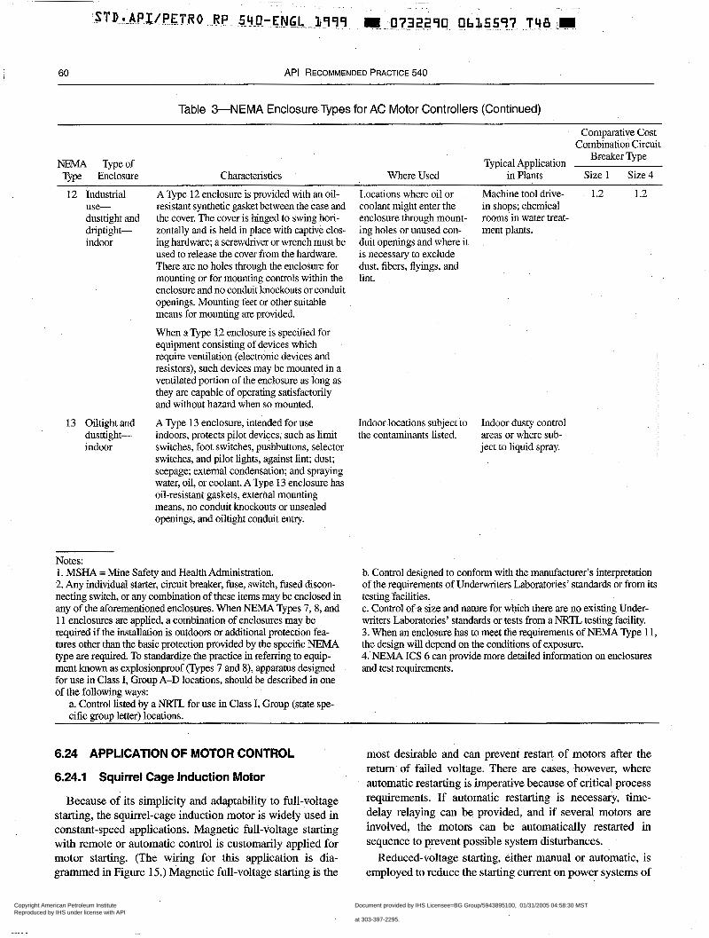
60 API RECOMMENDED PRACTICE 540
Table 3-NEMA Enclosure Types for AC Motor Controllers (Continued)
Comparative Cost Combination Circuit
NEMA Typeof T m Enclosure Characteristics
Typical Application Breaker Type
Where Used in Plants Size 1 Size 4
12 Industrial use- dusttight and driptight- indoor
13 Oiltight and
indoor dusttight-
A Type 12 enclosure is provided with an oil- resistant synthetic gasket between the case and the cover. The cover is hinged to swing hori- zontally and is held in place with captive clos- ing hardware; a screwdriver or wrench must be used to release the cover from the hardware. There are no holes through the enclosure for mounting or for mounting controls within the enclosure and no conduit knockouts or conduit openings. Mounting feet or other suitable means for mounting are provided.
When a Type 12 enclosure is specified for equipment consisting of devices which require ventilation (electronic devices and resistors), such devices may be mounted in a ventilated portion of the enclosure as long as they are capable of operating satisfactorily and without hazard when so mounted.
A Type 13 enclosure, intended for use indoors, protects pilot devices; such as limit switches, foot switches, pushbuttons, selector switches, and pilot lights, against lint; dust; seepage; external condensation; and spraying water, oil, or coolant. A Type 13 enclosure has oil-resistant gaskets, external mounting means, no conduit knockouts or unsealed openings, and oiltight conduit entry.
Locations where oil or Machine tool drive- 1.2 1.2 coolant might enter the in shops; chemical enclosure through mount- rooms in water treat- ing holes or unused con- ment plants. duit openings and where it is necessary to exclude dust, fibers, flyings, and lint.
Indoor locations subject to Indoor dusty control the contaminants listed. areas or where sub-
ject to liquid spray.
Notes: 1. MSHA = Mine Safety and Health Administration. 2. Any individual starter, circuit breaker, fuse, switch, fused discon- necting switch, or any combination of these items may be enclosed in any of the aforementioned enclosures. When NEMA Types 7,8, and 11 enclosures are applied, a combination of enclosures may be required if the installation is outdoors or additional protection fea- tures other than the basic protection provided by the specific NEMA type are required. To standardize the practice in referring to equip- ment known as explosionproof (Types 7 and S), apparatus designed for use in Class I, Group A-D locations, should be described in one of the following ways:
a. Control listed by a NRTL for use in Class I, Group (state spe-
b. Control designed to conform with the manufacturer's interpretation of the requirements of Underwriters Laboratories' standards or from its testing facilities. c. Control of a size and nature for which there are no existing Under- writers Laboratories' standards or tests from a NRTL testing facility. 3. When an enclosure has to meet the requirements of NEMA Type 1 1, the design will depend on the conditions of exposure. 4.' NEMA ICs 6 can provide more detailed information on enclosures and test requirements.
cific group letter) locations.
6.24 APPLICATION OF MOTOR CONTROL
6.24.1 Squirrel Cage Induction Motor
Because of its simplicity and adaptability to full-voltage starting, the squirrel-cage induction motor is widely used in constant-speed applications. Magnetic full-voltage starting with remote or automatic control is customarily applied for motor starting. (The wiring for this application is dia- grammed in Figure 15.) Magnetic full-voltage starting is the
most desirable and can prevent restart of motors after the return of failed voltage. There are cases, however, where automatic restarting is imperative because of critical process requirements. If automatic restarting is necessary, time- delay relaying can be provided, and if several motors are involved, the motors can be automatically restarted in sequence to prevent possible system disturbances.
Reduced-voltage starting, either manual or automatic, is employed to reduce the starting current on power systems of
Copyright American Petroleum Institute Reproduced by IHS under license with API
Document provided by IHS Licensee=BG Group/5943895100, 01/31/2005 04:58:30 MSTQuestions or comments about this message: please call the Document Policy Groupat 303-397-2295.
--`,`,,,`,`,`,,,```,,``,,`,``,,-`-`,,`,,`,`,,`---
STDmAPIlPETRO RP 540-ENGL L999 e 0732290 Ob15598 984 W
ELECTRICAL iNSTALLATlONS IN PETROLEUM PROCESSING PLANTS 61
limited capacity if the reduced-starting torque is adequate winding is brought out through slip rings and connected to a for the connected equipment. Reduced-voltage starting also variable resistor or regenerative system. This arrangement is employed when the driven load demands smooth starting. provides selective speed control under varying conditions of Several methods of applying reduced-voltage starting are load (see Figure 17). available: The primary control device for starting a wound-rotor
a. The autotransformer method offers variations in starting motor is usually the same as that used for a squirrel-cage
torque through selective starting taps. It provides maximum induction motor. The secondary device for regulating the
starting torque with minimum line current (see Figure 16). speed of a wound-rotor motor consists of an adjustable
b. The series resistor or reactor method offers simplicity of primary and secondary control devices so that the motor resistor or rheostat. It is general practice to interlock these
design and uses a more economical starter. cannot be started except when the resistor is set in mini- c. Wye-delta starting is also an economical method of mum-speed position. reduced-voltage starting but produces a lower starting torque than the other methods. Application of wound rotor motors in petrochemical envi-
ronments should be carefully reviewed because of the spark- d. The solid-state reduced-voltage starting method provides a ing nature of the brushes and slip smooth, stepless acceleration with current-limit control adjustable between the limits of approximately 150% and 425% of motor full-load current. 6.25 MEANS OF DISCONNECTION
Means of disconnection are discussed in NFPA 70. 6.24.2 Synchronous Motor
6.26 COORDINATION OF CONTROLLER The synchronous motor is applied principally in the large
horsepower class, greater than or equal to 500 HP. Because of its limited starting characteristics, the synchronous motor is
APPLICATIONS WITH FUSES OR CIRCUIT BREAKERS ON LOW-VOLTAGE SYSTEMS
generally started under no-load conditions with DC field 6.26.1 ' Normal Operation and Fault Conditions excitation automatically applied when the motor approaches synchronous speed. Variable field excitation may be used dur- ing normal operation to provide power factor con-ection and should be specified if required.
As is the case for squirrel-cage induction motors, full- and reduced-voltage controllers are available for starting; the selection depends on the local power source and operating conditions. There is a similarity in control except that the out- of-step protection automatically stops the motor when the motor drops out of synchronism.
A controller for a synchronous motor will generally include the following functions in addition to the functions of a controller for a squirrel-cage induction motor:
a. Protection of the field against overcurrents in normal or out-of-step operation. b. Automatic field application that is responsive to the definite time, the relative frequency of the current in the field and sta- tor, the power factor of the current to the stator winding, and other variables that may be used to obtain the desired result.
Both AC and DC meters should be provided.
6.24.3 Wound-Rotor Induction Motor
i I
The wound-rotor induction motor meets the operating demands of controlled starting, in-rush current, and adjust- able speeds with high starting torque. It is suitable for a high- inertia load where critical operations may require closely con- trolled acceleration. Starting facilities are similar to those of the squirrel-cage induction motor, except that the motor
A motor controller must be capable of starting and stop- ping its rated motor horsepower and interrupting motor locked-rotor current. Normally, the controller cannot interrupt fault currents resulting from short circuits and grounds so a circuit breaker, motor circuit protector, or a set of fuses is installed ahead of the controller. The protective devicesmust have sufficient capacity to interrupt the current safely and must be fast enough to clear the fault without damage to the contactor and overcurrent devices. They must also carry locked-rotor current long enough to allow the motor to accel- erate to rated speed without opening the motor circuit and should preferably protect against excessive locked-rotor time. In addition, they should keep motor damage to a minimum in case of a fault within the motor.
The complete motor protection package normally consists of a disconnect device, fault-current protection, a contactor, time- lag overcurrent protection, and associated auxiliary devices. The disconnect and fault-current protection are often combined in a circuit breaker. Even though some components may be combined, all of these protective features must be included.
6.26.2 Fuse and Circuit Breaker Considerations
NFPA 70 provides general information on fuses and circuit breakers.
6.26.2.1 Fuses
Dual element (time-delay) fuses are better suited for motor branch-circuit protection than are fuses that open
Copyright American Petroleum Institute Reproduced by IHS under license with API
Document provided by IHS Licensee=BG Group/5943895100, 01/31/2005 04:58:30 MSTQuestions or comments about this message: please call the Document Policy Groupat 303-397-2295.
--`,`,,,`,`,`,,,```,,``,,`,``,,-`-`,,`,,`,`,,`---
62 API RECOMMENDED PRACTICE 540
without delay; the time-delay feature avoids possible fuse opening during the period of high motor starting current. This allows the fuse to be sized more closely to the motor's rated full-load current.
Cun-ent-limiting fuses are also commonly used for this ser-
I
vice because of the following:
a. For faults, they operate within I/2-cycle to reduce the dam- age caused by short-circuit current. b. The magnitude of the short-circuit current is actually lim- ited to less than the available short-circuit current, which may allow the use of smaller conductors in. branch circuits. The fast operation of most fuses, however, makes it difficult and often impossible to coordinate them with other short-circuit protective devices. c. Current-limiting fuses are not subject to aging; therefore, an ultimate false operation is avoided when these devices are used.
6.26.2.2 Circuit Breakers
It is essential to select a circuit breaker capable of closing into, carrying, and interrupting the highest fault current avail- able at the point of installation.
6.27 OVERLOAD PROTECTION: SPECIAL APPLICATIONS
When a motor is to be used to drive a high-inertia load that requires a long time to accelerate to normal speed, a check should be made to determine if a special form of overload protection will be required. This will usually be the case if a standard protective device, set at the maximum current value affording proper protection for the motor, trips the motor off the line during the starting period.
To provide uninterrupted starting and at the same time pro- vide the desired degree of protection against sustained high starting currents, it may be necessary, in some cases, to use a thermal device that is built into the motor stator winding. In other cases, it may be necessary to use long-time induction- disk or solid-state relays that are adjustable to suit the starting conditions, or to supply current to the overload protective device through a saturable core reactor or current transformer with characteristics suitable for limiting the current to the protective device during the starting period. If one of these forms of protection will not suffice, consideration should be given to other means of providing the desired degree of pro- tection. If the ambient temperature varies, thermally compen- sated relays may be used.
A speed sensor or switch coupled to the motor shaft can also be integrated into the control system, particularly with the use of timing relay(s). Many of the multifunction protec- tion relays (solid-state relays) available integrate this and other protective features.
6.28 VOLTAGE LIMITATIONS
In many cases, on a privately owned industrial supply system, it is practical to tolerate voltage fluctuations some- what in excess of values that generally would be considered unacceptable on other systems. When a large motor is to be installed at a point where severe voltage dips will result, a check will determine whether the motor terminal voltage will be sufficient during the starting period to permit the motor to bring its load up to speed within a satisfactory time, and whether the resulting voltage disturbance will be acceptable, considering the requirements of other electrical equipment supplied by the system. Where the terminal volt- age will be abnormally low, approaching the value at which the undervoltage device in a standard controller is designed to operate, it is recommended that the specification for the controller include the anticipated range of voltage from the minimum during starting to the maximum during normal operation.
6.29 APPLICATION OF OUTDOOR AND INDOOR TYPES
6.29.1 Outdoor -Type
It is common practice to install electric motors and driven equipment outdoors without protection from the weather, unless there is some good reason for providing a building or other form of shelter. Outdoor-type controllers may be used with these motors. The main consideration in this application is to avoid the use of buildings and other shelters as much as possible so that the possibility of an accumulation of flamma- ble vapors or gases is reduced. Enclosures for controllers installed outdoors must meet all service requirements of the location.
6.29.2 Indoor -Type
Indoor-type controllers are sometimes used regardless of the location of the associated motors. It may be more eco- nomical to use indoor equipment in a building located in an unclassified area than to.provide outdoor controllers that are suitable for all conditions of service.
6.30 PUSHBUTTON STATIONS
6.30.1 Location
If undervoltage protection is required, the pushbutton for operating the controller is generally of the momentary-con- tact, start-stop type and is installed in sight of and near the motor and its driven equipment and in a position that will facilitate ease and safety of operation. If a pushbutton is installed on or near a controller that is remote from the motor controlled, the pushbutton is generally of the stop- type installed only for the purpose of stopping the motor in an emergency.
Copyright American Petroleum Institute Reproduced by IHS under license with API
Document provided by IHS Licensee=BG Group/5943895100, 01/31/2005 04:58:30 MSTQuestions or comments about this message: please call the Document Policy Groupat 303-397-2295.
--`,`,,,`,`,`,,,```,,``,,`,``,,-`-`,,`,,`,`,,`---
STD-API' /PETRO RP 540-ENGL 1999 m 0732290 Ob15b00 3b2 H
ELECTRICAL INSTALLATIONS IN PETROLEUM PROCESSING PLANTS 63
6.30.2 Undervoltage Release 6.31 ADDITIONAL REFERENCES
In installations where undervoltage release instead of The following additional references are helpful in prepar- undervoltage protection is to be provided, as in float-Oper- ing definitive specifications and correctly applying motors ated pumps, pressure-operated compressors, and other pilot- and controllers: operated equipment, which function automatically on an on- off cycle, the pushbutton is generally of the maintained-con- tact type, wired in series with the pilot device.
a. b. C. d. e. f.
AGMA 6019-E. UL 674 and UL 698. NEMA ICs 1 and NEMA MG 2. API 541 data sheet guide. API 546 data sheet guide. EEE Std 242.
Copyright American Petroleum Institute Reproduced by IHS under license with API
Document provided by IHS Licensee=BG Group/5943895100, 01/31/2005 04:58:30 MSTQuestions or comments about this message: please call the Document Policy Groupat 303-397-2295.
--`,`,,,`,`,`,,,```,,``,,`,``,,-`-`,,`,,`,`,,`---
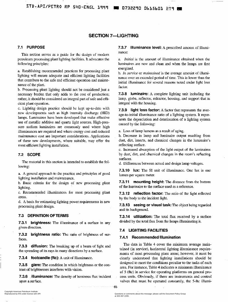
STD-APIIPETRO RP $40-ENGL L999 II 0732290 ObLSbOL 2T9 m
SECTION 7-LIGHTING
7.1 PURPOSE 7.3.7 illuminance level: A prescribed amount of illumi-
This section serves as a guide for the design of modern petroleum processing plant lighting facilities. It advocates the following principles:
a. Establishing recommended practices for processing plant lighting will ensure adequate and efficient lighting facilities that contribute to the safe and efficient operation and mainte- nance of the plant. b. Processing plant lighting should not be considered just a necessary burden that only adds to the cost of production; rather, it should be considered an integral part of safe and effi- cient plant operation. c. Lighting design practice should be kept up-to-date with new developments such as high intensity discharge (HID) lamps. Luminaires have been developed that make effective use of metallic additive and quartz light sources. High-pres- sure sodium luminaires are commonly used where high illuminances are required and where energy cost and reduced maintenance cost are important considerations. Applications of these new developments, where suitable, may offer the most efficient lighting installation.
7.2 SCOPE
nance:
a. Znitial is the amount of illuminance obtained when the luminaires are new and clean and when the lamps are first energized. b. In sewice or maintained is the average amount of illumi- nance over an extended period of time. This is lower than the initial illuminance for several reasons noted under light loss factor.
7.3.8 luminaire: A complete lighting unit including the lamp, globe, reflector, refractor, housing, and support that is integral with the housing.
7.3.9 light loss factor: A'factor that represents the aver- age-to-initial illuminance ratio of a lighting system. It repre- sents the depreciation and deterioration of a lighting system caused by the following:
a. Loss of lamp lumens as a result of aging. b. Decrease in lamp and luminaire output resulting from dust, dirt, insects, and chemical changes in the luminaire's reflecting surface. c. Increased absorption of the light output of the luminaires by dust, dirt, and chemical changes in the room's reflecting surfaces.
The material in this section is intended to establish the fol- d. Differences between actual design lamp voltages. lowing:
a. A general approach to the practice and principles of good lumen per square meter. lighting installation and maintenance. b. ~~~i~ for the design of new processing plmt 7.3.11 mounting height: The distance from the bottom lighting. of the luminaire to the surface used as a reference. c. Recommended illuminances for most processing plant 7.3.12 reflection factor: The ratio of the light reflected areas. by the body to the incident light. d. A basis for estimating lighting power requirements in new processing plant design. 7.3.13 seeing or visual task The object being regarded
7.3 DEFINITION OFTERMS 7.3.14 utilization: The total flux received by a surface 7.3.1 brightness: The illuminance of a in any dwided by the total flux from the lamps illuminating it. given direction.
7.3.2 brightness ratio: The ratio of brightness of sur- faces.
7.3.3 diffusion: The breaking up of a beam of light and The data in Table 4 cover the minimum average main-
the spreading of its rays in many directions by a surface. tained (in service), horizontal lighting illuminance require- ments of most processing plant areas; however, it must be
7.3.4 footcandle (ftc): A unit of illuminance. clearly understood that lighting installations should be
7.3.10 lux: The SI unit of illuminance. One lux is one
and its background.
7.4 LIGHTING FACILITIES
7.4.1 Recommended Illumination
7.3.5 glare: The condition in which brightness or the con- trast of brightnesses interferes with vision.
designed to meet the conditions peculiar to the tasks of each area. For instance, Table 4 indicates a minimum illuminance of 5 (ftc) in service for operating platforms on general pro-
7.3.6 illuminance: The density of luminous flux incident cess units. Obviously, ifthere are instruments -and control upon a surface. valves that must be operated constantly, the 5-ftc illumi-
"
65
Copyright American Petroleum Institute Reproduced by IHS under license with API
Document provided by IHS Licensee=BG Group/5943895100, 01/31/2005 04:58:30 MSTQuestions or comments about this message: please call the Document Policy Groupat 303-397-2295.
--`,`,,,`,`,`,,,```,,``,,`,``,,-`-`,,`,,`,`,,`---
! 66 API RECOMMENDED PRACTICE 540
, nance is insufficient. Supplemental lighting on the immedi- ate contro~ area or a general increase in the illuminance on that platform is necessary. In this sense, the data shown in Table 4 serve only as a guide to good lighting practice.
Note: These illuminances are not intended to be mandatory by enactment into law; they are a recommended practice to be consid- ered in the design of new facilities.
a. Indicates vertical illuminance. b. Refer to local Coast Guard, port authority, or governing body for required navigational lights. c. The use of many areas in petroleum and chemical plants is often different from what the designation may infer. The areas are generally small, their occupancy is low (restricted to plant personnel) and infrequent, and they are only occupied by per- sonnel trained to conduct themselves safely under unusual conditions. For these reasons, illuminances may be different from those recommended for other industries. and for com- mercial, educational, or public areas. d. Refer to local Federal Aviation Administration regulations for required navigational and obstruction lighting and marking. e. Refer to Tables 7.2A and 7.2B in API RP 14F for recom- mended illumination levels for offshore production platforms.
7.4.2 Petroleum Processing Plant Areas
As shown in Table 4, the three basic areas to consider when planning lighting facilities are process areas, nonprocess areas, and buildings. Buildings peculiar to process and non- process areas have been included in Table 4.
The three basic areas are broken down into more specific areas or activities. Under process areas and the more specific areas of general process units, minimum lighting require- ments are given for areas such as pump rows, heat exchang- ers, and operating platforms.
7.4.3 Lamp Types
The following types of lamps are commercially available and frequently used in refinery installations:
a. Incandescent, including tungsten and halogen. b. Fluorescent. c. Mercury vapor. d. Metal halide. e. High-pressure sodium.
Incandescent and fluorescent lamps, including halogen and tungsten, can be used in luminaires with direct, semidi- rect, and general-diffuse outputs, while high-intensity dis- charge lamps can be used in luminaires with direct and semidirect outputs. Efficacies for incandescent lamps range from 4 to 24 lumens per watt ( l m and for fluorescent lamps range from 75 to 80 (lm/W).
Compared with incandescent lamps, mercury vapor lamps offer the advantages of longer average life and higher
lumen output; however, with the advent of metal halide and high-pressure sodium lamps, the mercury vapor lamp is considered by many to be obsolete, except in existing plants having similar lamps. The mercury vapor lamp is consid- ered obsolete because of its rapid lumen depreciation and low lumens-per-watt (1mnV) characteristics. Also, the warm-up period and restrike may vary between 3 minutes and 7 minutes. As with other HID lamps, these ballasts have power factors in the 40% to 50% range unless corrected; capacitor correction results in power factors in the 90% range. Efficacies for mercury vapor lamps range from 38 to 63 l m , excluding ballast losses. Average lamp life is 24,000 hours, but it is recommended that lamps be replaced at 16,000 hours due to rapid lumen depreciation.
Metal halide lamps are similar in construction to mercury vapor lamps. The difference is that metal halides are added to the mercury and argon in the arc tube. The efficacies are improved to the range of 75 lm/W to 125 I N , excluding bal- last loss. The color rendering is quite white and is usually superior to the phosphor-coated mercury vapor lamp. The warm-up time for metal halide lamps is 2 minutes to 4 min- utes, and restrike time varies from 5 minutes to 15 minutes, depending on the type. Power factors in the 90% range can be obtained. Lamp life varies from 3,000 hours to 20,000 hours. Metal halide lamps have more rapid lumen depreciation than do mercury vapor lamps, and have high surface operating tem- peratures which must be considered before application in clas- sified locations. The lamp life and lumen output are affected by burning position.
Currently, most engineering activities by lamp manufactur- ers are focused on improvements in the overall efficiencies and life of the metal halide lamps. A series of pulse start metal halide lamps have been developed with features of improved lamp life, lumen maintenance, and the use of more efficient ballast systems. These lamps have wattages ranging from 150 W to 400 W with efficacy 90 I N to 110 l e , lamp life of 15,000 to 30,000 hours; improved warm-up time of 2 minutes; and restrike time of 3 minutes to 4 minutes. A 33% improve- ment in lumen maintenance can be seen in these lamps.
High-pressure sodium lamps have efficacies that range from 77 lm/W to 140 lm/W, depending on size. The color rendition is a distinct orange. Warm-up time for high-pressure sodium lamps is from 3 minutes to 4 minutes. Restrike time is less than 1 minute, and instant restrike devices are offered for 50-W to 150-W high-pressure sodium lamps. Power factors range from 40% to 99% depending on the ballast type and the age of the lamp. Lamp life is 24,000 hours.
HID lighting may be supplemented by incandescent or fluorescent lighting which would provide illumination dur- ing the initial warm-up time and during the restrike time after an extinction caused by voltage dips in the 10% to 60% range, depending on ballast type. If required, a push-to-test switch can be installed with a fixture that uses the re-strike feature. This switch will allow the testing of the restrike dur-
., ,
Copyright American Petroleum Institute Reproduced by IHS under license with API
Document provided by IHS Licensee=BG Group/5943895100, 01/31/2005 04:58:30 MSTQuestions or comments about this message: please call the Document Policy Groupat 303-397-2295.
--`,`,,,`,`,`,,,```,,``,,`,``,,-`-`,,`,,`,`,,`---
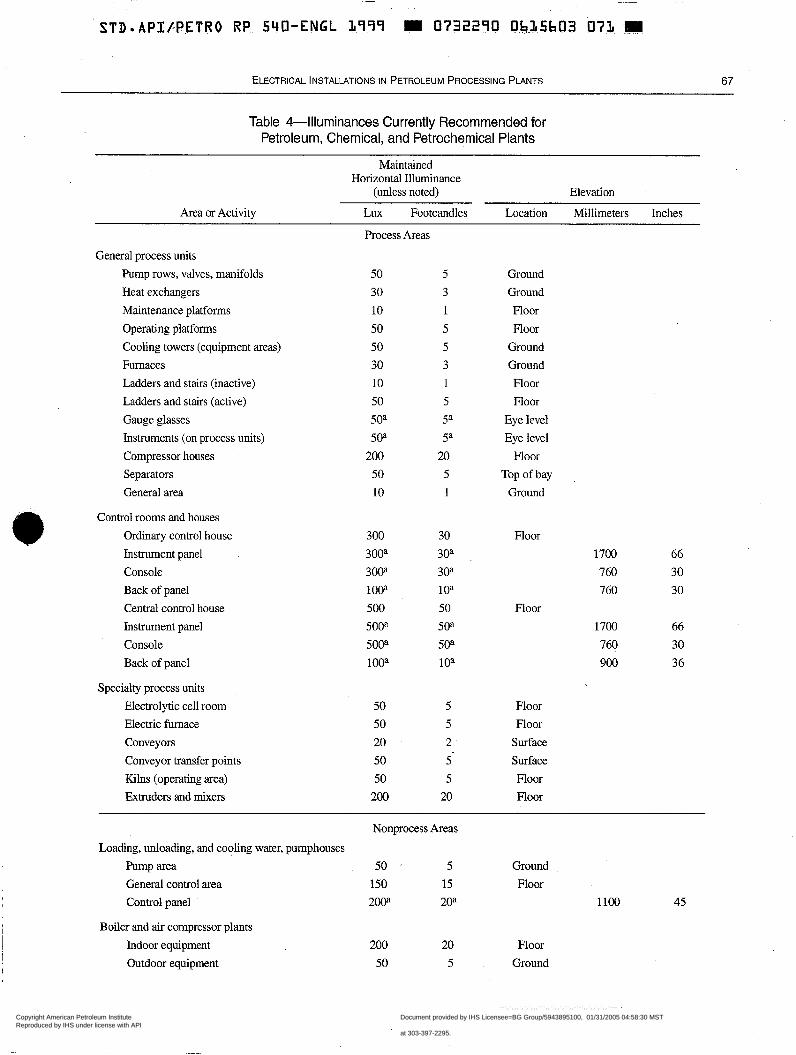
STD.APJ.b.PETR0 RP 540-ENGL 1999.- E 0732230 ObJ15b03 073 : m ~
ELECTRICAL INSTALLATIONS IN PETROLEUM PROCESSING PIANTS 67
Table 4-Illuminances Currently Recommended for Petroleum, Chemical, and Petrochemical Plants
Area or Activity
Maintained Horizontal Illuminance
(unless noted) Elevation
Lux Footcandles Location Millimeters Inches
General process units Pump rows, valves, manifolds Heat exchangers Maintenance platforms Operating platforms Cooling towers (equipment areas) Fumaces Ladders and stairs (inactive) Ladders and stairs (active) Gauge glasses Instruments (on process units) Compressor houses Separators General area
e Control rooms and houses Ordinary control house Instrument panel Console Back of panel Central control house Instrument panel Console Back of panel
Specialty process units Electrolytic cell room Electric furnace Conveyors Conveyor transfer points Kilns (operating area) Extruders and mixers
Process Areas
50
30
10 50
50 30
10
50
5Oa 5Oa
200 50
10
300
30Oa
30P
100a 500 5ooa 5002
l0Oa
50 50
20 50 50
200
5 3 1 5 5
3 1
5 5a
5a
20 5 1
30
3oa 30a
1 oa
50
50a
50a
102
5 5
2 - 5' 5
20
Ground Ground Floor Floor
Ground Ground Floor Floor
Eye level Eye level
Floor Top of bay
Ground
Floor 1700 66
760 30
760 30
Floor 1700 66
760 30
900 36
Floor Floor
Surface Surface Floor Floor
Nonprocess Areas Loading, unloading, and cooling water, pumphouses
Pump area 50 5 Ground General control area 150 15 Floor Control panel 2w 20a
Boiler and air compressor plants Indoor equipment Outdoor equipment
200 20 Floor 50 5 Ground
1 loo 45
Copyright American Petroleum Institute Reproduced by IHS under license with API
Document provided by IHS Licensee=BG Group/5943895100, 01/31/2005 04:58:30 MSTQuestions or comments about this message: please call the Document Policy Groupat 303-397-2295.
--`,`,,,`,`,`,,,```,,``,,`,``,,-`-`,,`,,`,`,,`---
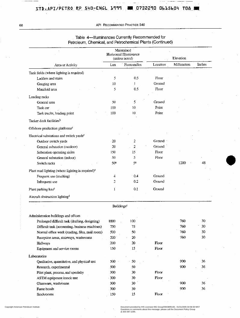
~~~~~~ ~ ~ ~~~~~ ~~~ ~~~~~ ~~~~
. .
.STR..-.API./PET.RO RP.. 540-EN.G.L 4999. . I I .-073??90 Ob.15b09 ,.TO~¿L,,m.,
68 API RECOMMENDED PRACTICE 540
i Table 4-Illuminances Currently Recommended for Petroleum, Chemical, and Petrochemical Plants (Continued)
Maintained Horizontal Illuminance
(unless noted) Elevation
Area or Activity Lux Footcandles Location Millimeters Inches
Tank fields (where lighting is required) Ladders and stairs 5 0.5 Floor
Gauging area 10 1 Ground
Manifold area 5 0.5 Floor
Loading racks General area 50 5 Ground
Tank car 100 10 Point Tank trucks, loading point 100 10 Point
Tanker dock facilitiesb
Offshore production platformse
Electrical substations and switch yardsc Outdoor switch yards 20 2 Ground General substation (outdoor) 20 2 Ground Substation operating aisles 150 15 Noor General substation (indoor) 50 5 Floor Switch racks 50a 5a 1200 48
Plant road lighting (where lighting is required)c Frequent use (trucking) 4 0.4 Ground Infrequent use 2 0.2 Ground
Plant parking lotsC 1 o. 1 Ground
Aircraft obstruction lightingd
Adminiswation buildings and offices Prolonged difficult task (drafting, designing) Difficult task (accounting, business machines) Normal office work (reading, files, mail room) Reception areas, stairways, washrooms Hallways Equipment and service rooms
Laboratories Qualitative, quantitative, and physical test Research, experimental Pilot plant, process, and specialty ASTM equipment knock test Glassware, washrooms Fume hoods Stockrooms
BuildingsC
lo00 100 760 30 750 75 760 30 500 50 760 30 200 ' 20 760 30 200 20 Floor 150 15 Floor
500 50 500 50 300 30 300 30 300 30 300 30 150 15
900 36 900 36
Floor Floor
900 36 900 36
Floor
Copyright American Petroleum Institute Reproduced by IHS under license with API
Document provided by IHS Licensee=BG Group/5943895100, 01/31/2005 04:58:30 MSTQuestions or comments about this message: please call the Document Policy Groupat 303-397-2295.
--`,`,,,`,`,`,,,```,,``,,`,``,,-`-`,,`,,`,`,,`---
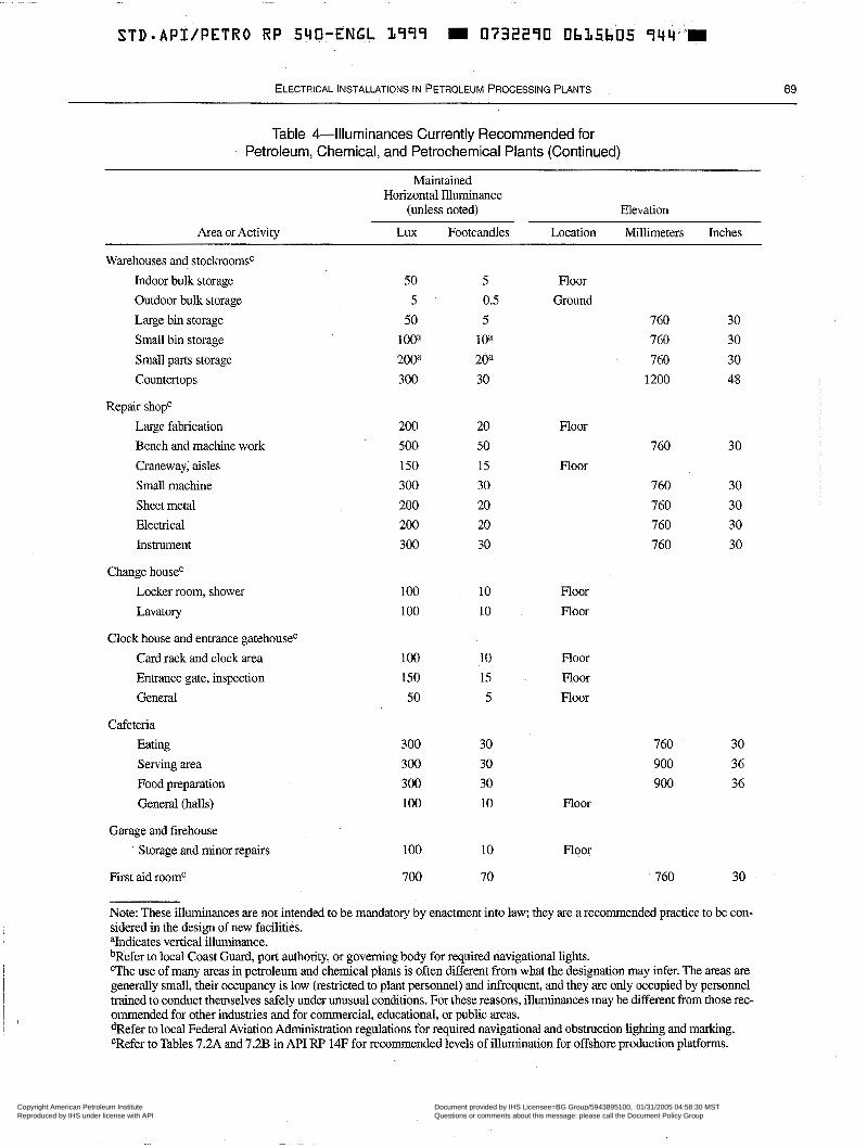
STD.API/PETRO RP 540-ENGL 1777 I 0732270 0635605 c l 4 4 ' * 1
ELECTRICAL lNSTALLATlONS IN PETROLEUM PROCESSING PLANTS 69
Table 4-Illuminances Currently Recommended for Petroleum, Chemical, and Petrochemical Plants (Continued)
Maintained Horizontal Illuminance
(unless noted) Elevation
Area or Activity Lux Footcandles Location Millimeters Inches
Warehouses and stockroomsC Indoor bulk storage Outdoor bulk storage Large bin storage Small bin storage Small parts storage Countertops
Repair shopC Large fabrication Bench and machine work Craneway, aisles Small machine Sheet metal Electrical Instrument
Change houseC Locker room, shower Lavatory
Clock house and entrance gatehouseC Card rack and clock area Entrance gate, inspection General
Cafeteria Eating Serving area Food preparation General (halls)
Garage and firehouse Storage and minor repairs
First aid roomc
50 5
50 1 ooa
20oa 300
200 500 150 300 200 200 300
100 1 O0
100 150 50
300 300 300 100
100
700
5 0.5 5
1 oa
20a 30
20 50 15 30 20 20 30
10 10
10 15 5
30 30 30 10
10
70
Floor Ground
760 760 760
1200
Floor 760
Floor 760 760 760 760
Floor Floor
Floor Floor Floor
30 30 30 48
30
30 30 30 30
760 30 900 36 900 36
Floor
Floor
760 30
Note: These illuminances are not intended to be mandatory by enactment into law; they are a recommended practice to be con- sidered in the design of new facilities.
bRefer to local Coast Guard, port authority, or governing body for required navigational lights. "The use of many areas in petroleum and chemical plants is often different from what the designation may infer. The areas are generally small, their occupancy is low (restricted to plant personnel) and infrequent, and they are only occupied by personnel trained to conduct themselves safely under unusual conditions. For these reasons, illuminances may be different from those rec- ommended for other industries and for commercial, educational, or public areas. dRefer to local Federal Aviation Administration regulations for required navigational and obstruction lighting and marking. eRefer to Tables 7.2A and 7.2B in API RP 14F for recommended levels of illumination for offshore production platforms.
vertical illuminance.
Copyright American Petroleum Institute Reproduced by IHS under license with API
Document provided by IHS Licensee=BG Group/5943895100, 01/31/2005 04:58:30 MSTQuestions or comments about this message: please call the Document Policy Groupat 303-397-2295.
--`,`,,,`,`,`,,,```,,``,,`,``,,-`-`,,`,,`,`,,`---
70 API RECOMMENDED PRACTICE 540
ing normal operation by interrupting power to the fixture. This testing method will ensure that the restrike will func- tion as intended after a major voltage dip or power failure.
7.5 LUMINAIRES
7.5.1 Selection
In choosing a luminaire, a separate study should be made for each application. Some of the factors influencing the final selection are appearance, efficiency, glare, density of equip- ment, frequency of operation, maintenance, required color rendition, and area classification.
7.5.2 Floodlighting
Floodlights provide area lighting at an economical cost. They must be located at suitable mounting heights and with unob- structed beam paths. Mounting can be on pipeways, vessel plat- forms, rigging structures, and floodlight poles. Floodlights are available with most lamp types, and with beam spreads from 10" to 18" (NEMA 1) to greater than 130" (NEMA 7).
7.5.3 Codes and Standards
Local codes, national codes, federal standards, profes- sional standards, and manufacturers' standards relate to spe- cific requirements that must be met in the construction and installation of a luminaire. Some codes and standards deal with fire and safety (electrical, mechanical, and thermal); others relate to performance and construction (materials and finishes). Conformance to the appropriate set of specifica- tion is often determined by certified laboratory tests. Certifi- cation is often denoted by an identifying label. Local code enforcement authorities may or may not require certification by an approved laboratory.
7.5.3.1 National Codes
NFPA 70, the Canadian EZectricaZ Code (CEC), and simi- lar codes in most major countries state specific electrical requirements which must be met by all electrical equipment, including luminaires.
7.5.3.2 National and International Standards
For electrical products, UL, CSA, and other similar organi- zations publish minimum safety standards that are in con- formance with electrical codes. Luminaires approved by these organizations will meet the standards that ensure that they are acceptable for installation and are able to provide sat- isfactory service.
7.5.3.3 Industry Standards
Industry standards are published by various organizations that generally utilize national technical' committees com-
prised of representatives from industry, inspection and protec- tion agencies, and manufacturers. Conformance to these standards is not necessarily required, but it does offer many advantages to the user when conformance is specified. Stan- dards organizations include the American Society for Testing and Materials (ASTM), Certified Ballast Manufacturers (CBM)17, IEEE, ES, NEMA, andANSI.
7.5.3.4 Manufacturers' Standards
Since codes and standards deal primarily with safety and performance, the specifier should be aware of the quality standards used by the manufacturer.
7.5.4 Ballast Considerations
Lamp ballasts must be taken into consideration when spec- ifying luminaires for purchase. For all lamp types requiring ballasts, there are a variety of ballasts available. The design engineer should consult with the luminaire and lamp repre- sentatives to get more details.
HID luminaires may be purchased with a variety of bal- last types having a range of power factors and costs: but with the introduction of the high-pressure sodhm lamp, a new ballast consideration has been introduced. Unlike other HID lamps, the high-pressure sodium lamp is one with dynamic characteristics over its life. By carefully specifying high-pressure sodium luminaire ballast-types, the design engineer can achieve a good power factor over the life of the lamp. The design engineer's considerations when selecting the type of ballast to be used are energy efficiency (losses), lamp life, lumen output, wiring and circuitry (number of fix- tures per circuit), and dip tolerance (ability to sustain the arc during a voltage dip).
Remote mounted ballasts are available to use with mercury vapor, metal halide or high-pressure sodium lighting fixtures. The distance that the ballast can be mounted away from the lamp is based on the type of lamp, wattage, ballast-to-lamp wire size, and whether an ignitor is involved. In general, bal- lasts for mercury vapor and metal halide lamps do not require ignitor, but ballasts for high-pressure sodium and the newer, low-wattage metal halide lamps require an ignitor for starting. The design engineer should consult with the ballast and lumi- naire representatives to determine the proper ballast-to-lamp distance and the minimum wire s i s required.
7.5.5 Application in Classified Locations
Some locations may be exposed to the release of flammable gases, vapors, or dusts. NFPA 70 requires that these locations be classified and sets forth rules for luminaires that may be
17Certified Ballast Manufacturers, 355 Lexington Avenue, 17th Floor, New York, New York 10017-6603.
Copyright American Petroleum Institute Reproduced by IHS under license with API
Document provided by IHS Licensee=BG Group/5943895100, 01/31/2005 04:58:30 MSTQuestions or comments about this message: please call the Document Policy Groupat 303-397-2295.
--`,`,,,`,`,`,,,```,,``,,`,``,,-`-`,,`,,`,`,,`---
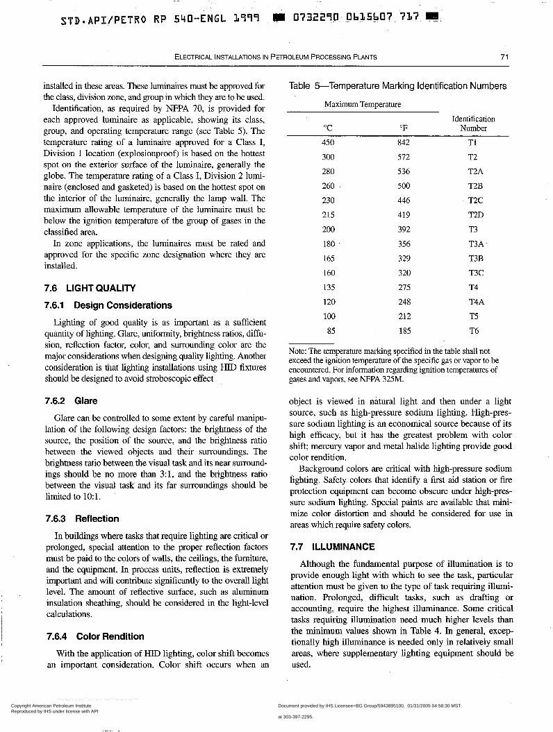
STD.API/PETRO RP 540-ENGL L999 1111 0732290- Oh&5bO7-7&7.m,
ELECTRICAL lNSTALLATlONS IN PETROLEUM PROCESSING PLANTS 71
installed in these areas. These luminaires must be approved for the class, division zone, and group in which they are to be used.
Identification, as required by NFPA 70, is provided for each approved luminaire as applicable, showing its class, group, and operating temperature range (see Table 5). The temperature rating of a luminaire approved for a Class I, Division 1 location (explosionproof) is based on the hottest spot on the exterior surface of the luminaire, generally the globe. The temperature rating of a Class I, Division 2 lumi- naire (enclosed and gasketed) is based on the hottest spot on the interior of the luminaire, generally the lamp wall. The maximum allowable temperature of the luminaire must be below the ignition temperature of the group of gases in the classified area.
In zone applications, the luminaires must be rated and approved for the specific zone designation where they are installed.
7.6 LIGHT QUALITY
7.6.1 Design Considerations
Lighting of good quality is as important as a sufficient quantity of lighting. Glare, uniformity, brightness ratios, dif i - sion, reflection factor, color, and surrounding color are the major considerations when designing quality lighting. Another consideration is that lighting installations using HID fixtures should be designed to avoid stroboscopic effect
7.6.2 Glare
Glare can be controlled to some extent by careful manipu- lation of the following design factors: the brightness of the source, the position of the source, and the brightness ratio between the viewed objects and their surroundings. The brightness ratio between the visual task and its near surround- ings should be no more than 3: 1, and the brightness ratio between the visual task and its far surroundings should be limited to 10: l.
7.6.3 Reflection
Table >Temperature Marking Identification Numbers
Maximum Temperature
"C Identification
"F Number 450
300
280
260 .
230
215
200
180
165
160
135
120
100
85
842
572
536
500
446
419
392
356
329
320
275
248
212
185
T l
T2
T2A T2B
T2C
T2D
T3
T3 A
T3B
T3C
T4
T4A
T5
T6
Note: The temperature marking specified in the table shall not exceed the ignition temperature of the specific gas or vapor to be encountered. For information regarding ignition temperatures of gases and vapors, see NFPA 325M.
object is viewed in natural light and then under a light source, such as high-pressure sodium lighting. High-pres- sure sodium lighting is an economical source because of its high efficacy, but it has the greatest problem with color shift; mercury vapor and metal halide lighting provide good color rendition.
Background colors are critical with high-pressure sodium lighting. Safety. colors that identify a first aid station or fire protection equipment can become obscure under high-pres- sure sodium lighting. Special paints are available that mini- mize color distortion and should be considered for use in areas which require safety colors.
In buildings where tasks that require lighting are critical or prolonged, special attention to the proper reflection factors 7.7 ILLUMINANCE must be paidto the colors of walls, the ceilings, the furniture, and the equipment. In process units, reflection is extremely important and will contribute significantly to the overall light level. The amount of reflective surface, such as aluminum insulation sheathing, should be considered in the light-level calculations.
Although the fundamental purpose of illumination is to provide enough light with which to see the task, particular attention must be given to the type of task requiring illumi- nation. Prolonged, difficult tasks, such as drafting or accounting, require the highest illuminance. Some critical
1 tasks requiring illumination need much higher levels than 7.6.4 Color Rendition the minimum values shown in Table 4. In general, excep-
tionally high illuminance is needed only in relatively small With the application of HID lighting, color shift becomes areas, where supplementary lighting equipment should be
an important consideration. Color shift occurs when an used.
Copyright American Petroleum Institute Reproduced by IHS under license with API
Document provided by IHS Licensee=BG Group/5943895100, 01/31/2005 04:58:30 MSTQuestions or comments about this message: please call the Document Policy Groupat 303-397-2295.
--`,`,,,`,`,`,,,```,,``,,`,``,,-`-`,,`,,`,`,,`---
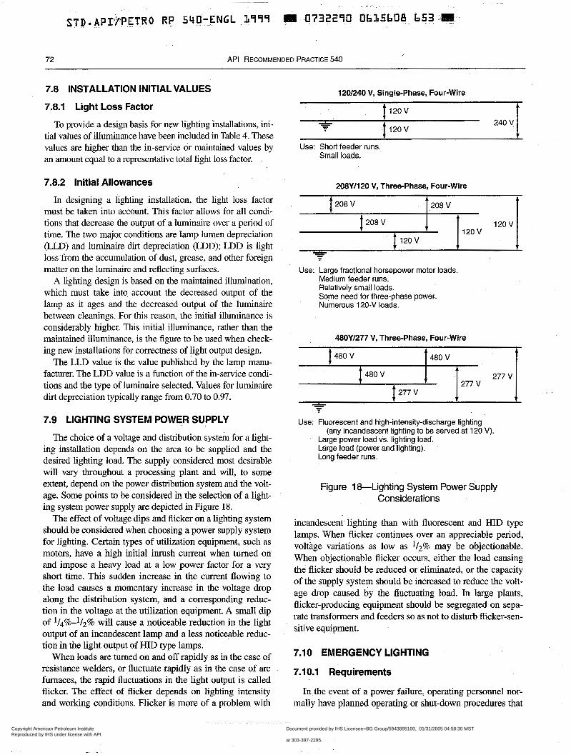
STD.API~FPETRO RP 5YO-ENGL L999 1111 0732290 Oh>ShOt!- h 5 3 .m
72 API RECOMMENDED PRACTICE 540
7.8 INSTALLATION INITIAL VALUES
7.8.1 Light Loss Factor
To provide a design basis for new lighting installations, ini- tial values of illuminance have been included in Table 4. These values are higher than the in-service or maintained values by an amount equal to a representative total light loss factor.
7.8.2 Initial Allowances
In designing a lighting installation, the light loss factor must be taken into account. This factor allows for all condi- tions that decrease the output of a luminaire over a period of time. The two major conditions are lamp lumen depreciation (LLD) and luminaire dirt depreciation (LDD); LDD is light loss from the accumulation of dust, grease, and other foreign matter on the luminaire and reflecting surfaces.
A lighting design is based on the maintained illumination, which must take into account the decreased output of the lamp as it ages and the decreased output of the luminaire between cleanings. For this reason, the initial illuminance is considerably higher. This initial illuminance, rather than the maintained illuminance, is the figure to be used when check- ing new installations for correctness of light output design.
The LLD value is the value published by the lamp manu- facturer. The LDD value is a function of the in-service condi- tions and the type of luminaire selected. Values for luminaire dirt depreciation typically range from 0.70 to 0.97.
7.9 LIGHTING SYSTEM POWER SUPPLY
The choice of a voltage and distribution system for a light- ing installation depends on the area to be supplied and the desired lighting load. The supply considered most desirable will vary throughout a processing plant and will, to some extent, depend on the power distribution system and the volt- age. Some points to be considered in the selection of a light- ing system power supply are depicted in Figure 18.
The effect of voltage dips and flicker on a lighting system should be considered when choosing a power supply system for lighting. Certain types of utilization equipment, such as motors, have a high initial inlush current when turned on and impose a heavy load at a low power factor for a very short time. This sudden increase in the current flowing to the load causes a momenlary increase in the voltage drop along the distribution system, and a corresponding reduc- tion in the voltage at the utilization equipment. A small dip of l/d%-l/z% will cause a noticeable reduction in the light output of an incandescent lamp and a less noticeable reduc- tion in the light output of HID type lamps.
When loads are turned on and off rapidly as in the case of resistance welders, or fluctuate rapidly as in the case of arc furnaces, the rapid fluctuations in the light output is called flicker. The effect of flicker depends on lighting intensity and working conditions. Flicker is more of a problem with
120/240 V, Single-phase, Four-Wire
120 v
120 v -L - - 240 V 1
Use: Short feeder runs. Small loads.
208Yll20 V, Three-phase, Four-Wire
Use: Large fractional horsepower motor loads. Medium feeder runs. Relatively small loads. Some need for three-phase power. Numerous 120-V loads.
48OYl277 V, Three-phase, Four-Wire
480 V 480 V t 480 V J 277 v 1
277 V 1 277 V 1 1 . ’
Use: Fluorescent and high-intensity-discharge lighting (any incandescent lighting to be served at 120 V).
Large power load vs. lighting load. Large load (power and lighting). Long feeder runs.
Figure 1 &-Lighting System Power Supply Considerations
incandescent lighting than with fluorescent and HID type lamps. When flicker continues over an appreciable period, voltage variations as low as l/2% may be objectionable. When objectionable flicker occurs, either the load causing the flicker should be reduced or eliminated, or the capacity of the supply system should be increased to reduce the volt- age drop caused by the fluctuating load. In large plants, flicker-producing equipment should be segregated on sepa- rate transformers and feeders so as not to disturb flicker-sen- sitive equipment.
7.10 EMERGENCY LIGHTING
7.10.1 Requirements
In the event of a power failure, operating personnel nor- mally have planned operating or shut-down procedures that
Copyright American Petroleum Institute Reproduced by IHS under license with API
Document provided by IHS Licensee=BG Group/5943895100, 01/31/2005 04:58:30 MSTQuestions or comments about this message: please call the Document Policy Groupat 303-397-2295.
--`,`,,,`,`,`,,,```,,``,,`,``,,-`-`,,`,,`,`,,`---
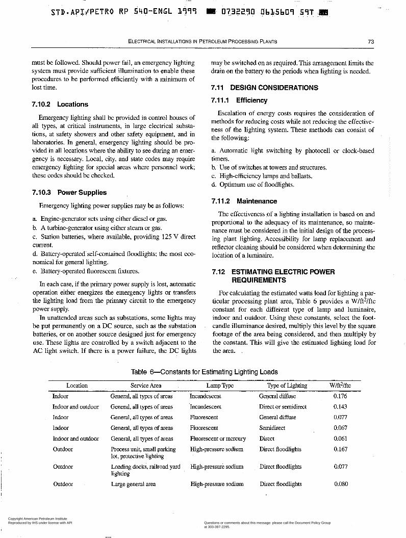
ELECTRICAL lNSTALL4TlONS IN PETROLEUM PROCESSING PLANTS 73
must be followed. Should power fail, an emergency lighting system must provide sufficient illumination to enable these procedures to be performed efficiently with a minimum of lost time.
7.10.2 Locations
Emergency lighting shall be provided in control houses of all types, at critical instruments, in large electrical substa- tions, at safety showers and other safety equipment, and in laboratories. In general, emergency lighting should be pro- vided in all locations where the ability to see during an emer- gency is necessary. Local, city, and state codes may require emergency lighting for special areas where personnel work these codes should be checked.
7.10.3 Power Supplies
Emergency lighting power supplies may be as follows:
a. Engine-generator sets using either diesel or gas. b. A turbine-generator using either steam or gas. c. Station batteries, where available, providing 125 V direct current. d. Battery-operated self-contained floodlights; the most eco- nomical for general lighting. e. Battery-operated fluorescent fixtures.
In each case, if the primary power supply is lost, automatic operation either energizes the emergency lights or transfers the lighting load from the primary circuit to the emergency power supply.
In unattended areas such as substations, some lights may be put permanently on a DC source, such as the substation batteries, or on another source designed just for emergency use. These lights are controlled by a switch adjacent to the AC light switch. If there is a power failure, the DC lights
may be switched on as required. This arrangement limits the drain on the battery to the periods when lighting is needed.
7.1 1 DESIGN CONSIDERATIONS
7.1 1.1 Efficiency
Escalation of energy costs requires the consideration of methods for reducing costs while not reducing the effective- ness of the lighting system. These methods can consist of the following:
a. Automatic light switching by photocell or clock-based timers. b. Use of switches at towers and structures. c. High-efficiency lamps and ballasts. d. Optimum use of floodlights.
7.1 1.2 Maintenance
The effectiveness ,of a lighting installation is based on and proportional to the adequacy of its maintenance, so mainte- nance must be considered in the initial design of the process- ing plant lighting. Accessibility for lamp replacement and reflector cleaning should be considered when determining the location of a luminaire.
7.12 ESTIMATING ELECTRIC POWER REQUIREMENTS
For calculating the estimated watts load for lighting a par- ticular processing plant area, Table 6 provides a W/ft2/ftc constant for each different type of lamp and luminaire, indoor and outdoor. Using these constants, select the foot- candle illuminance desired, multiply this level by the square footage of the area being considered, and then multiply by the constant. This will give the estimated lighting load for the area.
Table 6-Constants for Estimating Lighting Loads
Location Service Area Lamp Type Type of Lighting Wlft2Iftc Indoor General, all types of areas Incandescent General diffuse 0.176 Indoor and outdoor General, all types of areas Incandescent Direct or semidirect 0.143 Indoor General, all types of areas Fluorescent General diffuse 0.077 Indoor General, all types of areas Fluorescent Semidirect 0.067 Indoor and outdoor General, all types of areas Fluorescent or mercury Direct 0.061 Outdoor Process unit, small parking High-pressure sodium Direct floodlights 0.167
lot, protective lighting Outdoor Loading docks, railroad yard High-pressure sodium Direct floodlights 0.077
lighting Outdoor Large general area High-pressure sodium Direct floodlights 0.080
Copyright American Petroleum Institute Reproduced by IHS under license with API
Document provided by IHS Licensee=BG Group/5943895100, 01/31/2005 04:58:30 MSTQuestions or comments about this message: please call the Document Policy Groupat 303-397-2295.
--`,`,,,`,`,`,,,```,,``,,`,``,,-`-`,,`,,`,`,,`---
74 API RECOMMENDED PRACTICE 540
7.13 ILLUMINANCE METERS
Portable, light-sensitive-cell meters are simple and conve- nient to use, but they are not precision instruments. Under the most favorable conditions, measurements made in the field should not be expected to have an accuracy greater than 5%. All light-sensitive cells have certain inherent characteristics that should be recognized.
Meters without color correction can accurately read only the type of illumination for which they are calibrated (usually light from a filament lamp at a color temperature of 7,700 K). Most meters are made with a color-correcting filter that changes cell response to a reasonably close approximation of the standard eye response curve, which will be sufficiently accurate for ordinary purposes.
Meters are usually calibrated with light perpendicular to the cell surface; light from oblique angles or diffused light will
~~ ____ ~~ ~ ~~ _____ ~ ~ ~ ~~~~
give lower-than-true values unless correction procedures me used. This is the cosine effect or angle-of-incidence effect. The error may be as much as 25% when the light is from side win- dows only. Most present day meters have a diffusing cover plate or some other device to ensure that light from all direc- tions is properly evaluated. A well-corrected cell has nearly a true cosine response at all angles of incidence. When using an uncorrected cell, d i r e c t light from a single source can be mea- sured by holding the cell perpendicular to the light source and multiplying the reading by the cosine of the angle of incidence.
All light-sensitive cells are subject to fatigue. Meter indi- cation drops slowly for several minutes until a constant value is reached. The effect is noticeable at high footcandle values. Prior to measurement, all recorded meters should be given as long an adaptation period as necessary before val- ues are recorded.
Copyright American Petroleum Institute Reproduced by IHS under license with API
Document provided by IHS Licensee=BG Group/5943895100, 01/31/2005 04:58:30 MSTQuestions or comments about this message: please call the Document Policy Groupat 303-397-2295.
--`,`,,,`,`,`,,,```,,``,,`,``,,-`-`,,`,,`,`,,`---
SECTION 8-WIRING
8.1 PURPOSE into the instrumentation circuits. Unless otherwise noted,
This section is intended as a guide for providing safe and spacing should be per API RP 552 or E E E 5 18.
reliable wiring systems for the petroleum processing industry. 8.4 CONDUIT SYSTEMS
and cable trays. (For general guidelines concerning overhead distribution methods, see 4.1 1.) Because most electrical installations within a processing plant are in classified loca- tions and are outdoors, this section pertains mainly to wiring practices for those locations.
8.3 GENERAL
8.3.1 All electrical installations should meet or exceed NFPA 70 requirements; ANSVIEEE C2 requirements: and federal, state, and local requirements.
8.3.2 All raceways and cable trays should be selected and installed in accordance with the area classification as defined in API RP 500 or 505 and with the requirements of NFPA 70 for the area classification.
8.4.1.2 The gasket material for conduit fittings and boxes should be neoprene or a plastic that is resistant to the process solids, liquids, and gases to which it may be exposed.
8.4.1.3 Conduits should be swabbed clean prior to the installation of wire and cable.
8.4.1.4 Commercial pulling compounds compatible with the jacket and insulation of the wire or cable being pulled should be used. Excess pulling compound should be removed before the conduit sealing compound is poured in the seal-fit- ting around the conductors. .
8.4.1 -5 Temporary openings in conduits should be plugged or capped to prevent moisture and foreign matter from enter- ing during the construction phase of a job.
8.3.3 The wiring methods used in the operating, utility, and 8.4.1.6 Conduit fittings and pull, splice, and junction boxes other similar areas of petroleum processing plants are: should be sized using dimensions and volume in accordance
a. Electrical conductors enclosed in conduit. b. Cable-Type MC and Type TC as defined by NFPA 70. 8.4.2 Rigid Metal Conduit
with NFPA 70.
8.3.4 Generally, the use of busways is limited to electrical 8.4.2.1 The qpe of rigid metal conduit to be installed rooms Or buildings, substations, rep& shops, and Other Simi- should be selected based on the type of exposure to which the lar locations. conduit is to be subjected and, when applicable, on past plant
8.3.5 The use of wireways should be restricted to short runs, where many electrical conductors may .be collected. Electrical conductors may be collected on motor starter racks and at entrances to relay or control cabinets in electrical and instrument rooms.
8.3.6 The use of electrical metallic tubing and intermediate metal conduit should be restricted to indoor, dry, unclassified locations, such as offices and laboratories, where the installa- tion would not be subject to mechanical damage.
experience.
8.4.2.2 The rigid metal conduit system selected should be composed of at least one of the following types:
a. Hot-dipped galvanized steel conduit, conduit elbows, and couplings used with ferrous fittings and enclosures having a protective coating of zinc and an outer finish. Where suitable for the environment, aluminum fittings and enclosures may be substituted for use with the steel conduit. Hot-dipped gal- vanized steel conduit should conform to ANSI C80. l .
8.3.7 The mechanical continuity of all raceways and the electrical continuity of metal raceways should be maintained throughout the electrical system. An additional grounding conductor installed with each power circuit should be consid-
b. Corrosion-resistant aluminum alloy conduit, conduit elbows, couplings, fittings, and enclosures containing not more than 0.4% copper. Aluminum conduit should conform to ANSI (30.5.
~
I ered. 8.4.2.3 Rigid metal conduit should be cut square and 8.3.8 Spacings between instrumentation circuits and power, lighting, and control circuits in raceways and cable 8.4.2.4 A rigid metal conduit bend should be made with a trays should be maintained to prevent introduction of noise radius of not less than the requirements found in NFPA 70.
reamed before threading. I
75
Copyright American Petroleum Institute Reproduced by IHS under license with API
Document provided by IHS Licensee=BG Group/5943895100, 01/31/2005 04:58:30 MSTQuestions or comments about this message: please call the Document Policy Groupat 303-397-2295.
--`,`,,,`,`,`,,,```,,``,,`,``,,-`-`,,`,,`,`,,`---
76 API RECOMMENDED PRACTICE 540
The radius must be greater than the minimum bending radius of the cable. A field bend should be made with equipment specifically intended for the purpose and made so that the conduit is not injured and the internal diameter is not effec- tively reduced.
8.4.2.5 Threaded rigid metal conduit and fittings should be used for outdoor installations and are generally preferred for indoor installations.
8.4.2.6 Threaded conduit joints should be coated with an approved electrically conductive sealant and corrosion inhibi- tor that is not harmful to the conductor insulation. Aluminum conduit joints should be coated with anti-seizing compounds specifically made for use with aluminum. Threaded joints should be made with at least three fully engaged threads, or five fully engaged threads for explosionproof connections.
8.4.2.7 Running conduit ,threads are not acceptable. The threads shall have a taper of 3/4-in./ft.
8.4.3 Intermediate Metal Conduit
8.4.3.1 The applicable requirements in 8.4.2 pertaining to rigid metal conduit also apply to intermediate metal conduit.
8.4.3.2 The intermediate metal conduit system should be composed of galvanized steel and should conform to UL 1242.
8.4.4 Rigid Nonmetallic Conduit
8.4.4.1 The type of rigid nonmetallic conduit to be installed should be selected based on cable-pulling resistance, construction techniques, and conduit exposure. Rigid nonme- tallic conduit should not be used in Class I, aboveground installations.
8.4.4.2 The rigid nonmetallic conduit system selected should be composed of thermoplastic conduit (Schedule 40 or Schedule SO), conduit elbows, couplings, and similar fittings of polyvinyl chloride or high-deqsity polyethylene. Light- wall plastic conduit should be installed only with a concrete encasement, and it should be used only when the insulation temperature limitation of the cable to be installed does not exceed the temperature limit for which the conduit is labeled. A field bend should be made with an approved bending means, preferably a heat box.
8.4.5 Liquidtight Flexible Metal Conduit
8.4.5.1 Liquidtight flexible metal conduit should have an integral grounding conductor, when available, and an outer liquidtight, nonmetallic, sunlight-resistant jacket. In some cases, an external bonding jumper may be required to meet NFPA 70 requirements.
8.4.5.2 Liquidtight flexible metal conduit should be installed with termination fittings approved for the purpose.
8.4.6 Abovegrade Installations
8.4.6.1 General
Rigid metal conduit, or cables in cable tray are considered the normal wiring methods for all outdoor above-grade instal- lations and for all indoor installations subject to moisture, .chemical fluids and solids, and mechanical damage.
In Class I, Division 2 locations and wet locations, conduit connections to equipment subject to vibration or movement should be made with approved liquidtight flexible metal con- duit not exceeding 915 mm (36 in.) in length and with an equipment grounding conductor.
Conduit unions should be installed directly adjacent to equipment, such as motors and motor starters, subject to replacement or removal for repairs. This allows malfunction- ing motors and motor starters to be removed without disturb- ing the conduit and supply conductors. Conduit unions. provided at explosionproof enclosures should also be explo- sionproof and should be located between the conduit seal fit- tings and the enclosures.
Expansion joints should be provided in long conduit runs that are required to compensate for thermal expansion and contraction.
Conduit of l/Z-in. size may be used for control panel, short- run instrumentation, and telephone wiring. Conduit of 3/4-in. size should be the minimum used for lighting, power, and motor-control wiring.
8.4.6.2 Conduit Systems in Wet and Corrosive Areas
Precautions should be taken to prevent galvanic and atmo- spheric .corrosion when metal conduit is installed in areas where continuous moisture may be present. In locations such as cooling towers, where excessive moisture is expected, cor- rosion-resistant conduit materials (aluminum and plastic- coated, rigid steel conduit) should be considered.
Plastic-coated rigid steel conduit systems should also be considered for use in areas where corrosive vapors or liquids may be prevalent. Galvanized conduit, couplings, and elbows with PVC coating bonded to the metal may be used for such systems. Careful attention should be given to the installation methods to maintain the integrity of the protective coating. Workers should use only roll-type benders and strap wrenches so that the plastic coating does not abrade or tear. All exposed conduit threads at the terminations should be thoroughly coated or covered with plastic sealant.
Epoxy-coated metal fittings and enclosures having cast metal covers, plastic-coated metal fittings, or suitable plastic enclosures should be considered where plastic-coated rigid steel or aluminum conduit systems are to be installed.
Copyright American Petroleum Institute Reproduced by IHS under license with API
Document provided by IHS Licensee=BG Group/5943895100, 01/31/2005 04:58:30 MSTQuestions or comments about this message: please call the Document Policy Groupat 303-397-2295.
--`,`,,,`,`,`,,,```,,``,,`,``,,-`-`,,`,,`,`,,`---

STD-API/PETRO RP 540-ENGL L999 W- 0732290. O.bL.SbJ3 TL0 W
ELECTRICAL INSTALLATIONS IN PETROLEUM PROCESSING PLANTS 77
8.4.6.3 Conduit Drainage
Provisions for drainage should be installed in the vertical drops of long, outside, above-grade conduit runs at the points at which the conduits enter buildings, switchgear, control panels, lighting panelboards, and other similar enclosures. Long, outside, above-grade conduit runs that are extended below grade should be provided with drain fittings in the ver- tical drops directly above grade. In areas of high humidity and rapidly changing temperatures, drain requirements should be reviewed and enforced.
8.4.6.4 Conduit Routing
Exposed conduit should be installed parallel with or at right angles to walls, columns, and beams. Adequate clearances from high-temperature surfaces should be established for ali conduit runs. Clearances of 152 mm (6 in.) from sufaces 45°C to 65°C (113°F to 149°F); and 305 mm (12 in.) from surfaces greater than 65°C (149°F) are recommended. Where it is necessary to route conduit close to high-temperature sur- faces, a high-reflectance thermal barrier should be installed between the conduit and the surface.
Generally, conduits should be rouied to allow pull boxes, junction boxes, and fittings to be accessed from platforms or structures without the use of scaffolding.
Wherever possible, conduit routing should be maintained at a specified minimum horizontal distance from high-fire- risk equipment. A distance of 7.6 m (25 ft) is often considered to be adequate. Conduits containing wiring that must be oper- able during a fire should be fireproofed when the conduits are installed closer than the specified minimum &stance from high-fire-risk areas.
Conduits and fittings should be spaced away from continu- ally moist surfaces.
Where portions of conduit runs are exposed to tempera- tures in excess of the design ambient temperature or where conduits have been fireproofed, additional derating of cable ampacity may be required.
8.4.6.5 Conduit Supports
All rigid metal conduit runs shall be properly fastened and supported at the intervals specified in NFPA 70. Standard conduit clamps and multiple conduit hangers are acceptable supports for most installations. One-hole malleable iron clamps, or other adequate methods, are recommended to sup- port conduits installed on pipeways or structures subject to vibration or movement. Conduit supports should be fabri- cated from a material or should have a plating from a material that minimizes galvanic action.
Conduits for main feeders and long parallel runs of conduit i for any service should not be directly supported from over- I head piping. Conduits also should not be directly supported
from insulated piping.
Conduit suppolts should be installed as close as practicable to vertical drops in horizontal conduit runs that support pen- dant-mounted lighting fixtures. Also, liquidtight flexible metal conduit should be supported only with devices that are used in standard trade practice and that are in strict accor- dance with the requirements of NFPA 70.
8.4.6.6 Conduit Terminations
Conduits that enter switchgear, motor control centers, and similar installations from below should project at least 25 mm (1 in.) above the finished floor or shall otherwise be termi- nated to provide for the addition of conduit fittings.
Spare conduits should be located nearest to the access openings to facilitate future cable installations. Spare con- duits terminating within buildings and outside enclosures should have a coupling flush with the floor and plugged with a recessed square-head plug.
Spare low-voltage conduits that originate at buildings housing electrical facilities and that are routed underground to structures or columns for future extension overhead should be capped above grade. These conduits should be limited in number at a structure or column and should be spaced at the location to permit the future installation of staggered pulled boxes that only minimally project beyond the structure.
It is preferred that threaded conduit entrances be provided as integral parts of sheet metal enclosures if conduits are to be terminated at these enclosures (both for outdoor enclosures and, if the area is continually damp, indoor enclosures). If threaded entrances have not been provided, field-welded hubs or approved screwtight conduit hub fittings that are watertight and provide a positive ground are acceptable.
Generally, all conduits terminating or originating in Class I locations should be terminated in threaded conduit entrances. When this requirement may be impractical for Class I, Divi- sion 2 indoor installations, locknut-bushing and double-lock- nut terminations with bonding jumpers and proper fittings may be substituted. This means of bonding applies to all intervening raceways, fittings, boxes, and enclosures between the classified location and the point of grounding of the elec- trical service equipment.
Conduit bushings should be used where conduits at boxes or other enclosures are terminated unless the box or enclosure design provides an equivalent protection.
8.4.6.7 Conduit Seals
Explosionproof seal fittings located in compliance with NFPA 70 should be provided in conduit systems in classified locations to minimize the passage through the conduit of gases, vapors, and flames from one portion of the electrical installation to another.
Seal fittings shall be poured with a compound recom- mended by the fitting manufacturer. The sealing compound
Copyright American Petroleum Institute Reproduced by IHS under license with API
Document provided by IHS Licensee=BG Group/5943895100, 01/31/2005 04:58:30 MSTQuestions or comments about this message: please call the Document Policy Groupat 303-397-2295.
--`,`,,,`,`,`,,,```,,``,,`,``,,-`-`,,`,,`,`,,`---
STD API(P.TTR.0 R P -53-O-EN.GL.. 3999
78 API RECOMMEND 1ED PRACTICE 540
and fiber dam used in the fittings should not be affected by the surrounding atmospheres or liquids and should not have a melting point below 93°C (199OF). Combination explosion- proof drain-seal fittings may be used in classified locations where conduit drainage is required.
All conduits entering process control houses above grade at petroleum processing plants should be provided with explosionproof seal fittings outside the building walls. All conduits originating at manholes within petroleum process- ing plants should be provided with explosionproof seal fit- tings at the points of entry to buildings and electrical equipment enclosures.
Conduits that depend on single-seal diaphragms or tubes to prevent process liquids or gases from entering their electrical conduit systems should be provided with seal fittings for blocking passage of the fluids and with a means of venting the fluids to the atmosphere. This includes conduits routed to canned pumps and to devices used for flow, pressure, and analysis measurement.
Underground conduit runs that are completely within a non- classified location, and enter buildings below grade, should be sealed at their terminations with a mastic or expanded-foam compound. The compound should be impervious to liquids that may be in the ground. Ends of short conduit sleeves through building walls, used for the entrance of cables, should be sealed with mastic or expanded-foam compound.
8.4.7 Underground Installations
8.4.7.1 Wiring Methods
Generally, hot-dipped galvanized rigid steel conduit or rigid nonmetallic conduit that is encased in concrete (per NFPA 70, 5014) should be used for underground conduit systems. Concrete-encased, rigid aluminum conduit should only be installed underground at those locations where prior performance has proven satisfactory and where it conforms with local codes and regulations. (Special requirements for the concrete envelope used with an aluminum conduit are found in 8.4.7.4.)
Rigid metal conduit should be used for underground instal- lations whenever an extra-high-strength installation, such as in an equipment foundation, is required, and it is preferred for underground installations where only one or two relatively short runs of conduit are to be installed.
Subject to local practices and site conditions, the use of underground, galvanized rigid steel conduit without continu- ous concrete encasement may be considered for certain installations. Normally, the underground conduit should be provided with additional corrosion protection, such as a fac- tory-applied plastic coating, a bitumastic coating, or a tape wrap. On low-investment installations where this protection may be omitted from underground conduit, additional protec- tion should be provided at the grade line where the conduits emerge above grade.
In certain applications, specifically approved direct burial cable may be used.
8.4.7.2 Conduit Size
A minimum size for a conduit for installation underground should be established. A 1-in. minimum size for a conduit is recommended; however, a 3/4-in. conduit installed under- ground to a single, isolated device, such as a motor control station or an instrument, is usually acceptable. A minimum size for an underground conduit for main distribution and for bulk cable routing between distribution centers should also be established.
The initial sizing of underground conduits for main distri- bution feeders should take into consideration the possible replacement of the conductors with a larger size to accommo- date a future increase in load.
8.4.7.3 Conduit Bank Configurations
Conduit bank configurations should contain sufficient con- duits for the present installation plus spare conduits for future use.
Consideration should be given to conduit bank configura- tions that will provide effective heat radiation when the duct banks contain power cables for mains and major feeders. The effect of certain duct bank configurations on cable ampacity is reflected in the ampacity tables of NFPA 70. Special calcu- lations are required to determine the ampacity of cables installed in duct bank configurations that are not covered by NFF'A 70. Consideration should also be given to conduit bank configurations and entry locations that provide the best rack- ing conditions at manholes.
A specified minimum separation should be established between the outside surfaces of conduits in conduit banks.
8.4.7.4 Concrete Envelope
The concrete envelope surrounding the rigid conduits should have a specified thickness on the top, bottom, and sides, Where reinforced conduit bank sections are required, the thickness of the concrete envelope should be increased accordingly. Where conduits come to grade, the envelope should be extended at least 76 millimeters (3 inches) above grade and should be sloped for water runoff.
Red-pigmented concrete containing at least 5.9 kg/m3 (10 lb/yd3 yard) of red iron oxide should be used for the enve- lope. The concrete should be a 17.25-mE'a (2,500-psi) mix- ture having a coarse aggregate not exceeding 19 mm (3/4-in.) in size. The concrete should have a low chloride content when aluminum conduit is encased.
8.4.7.5 Underground Conduit Bank Routing
The location of all underground conduit bank runs should be selected with consideration for future structural installa-
Copyright American Petroleum Institute Reproduced by IHS under license with API
Document provided by IHS Licensee=BG Group/5943895100, 01/31/2005 04:58:30 MSTQuestions or comments about this message: please call the Document Policy Groupat 303-397-2295.
--`,`,,,`,`,`,,,```,,``,,`,``,,-`-`,,`,,`,`,,`---
ELECTRICAL INSTALLATIONS IN PETROLEUM PROCESSING PLANTS 79
tions in the area. Generally, underground conduit runs for main feeders and all conduit bank runs should be routed par- allel to plant coordinates and roadways and should not cross congested manufacturing or paved areas. Conduit banks should not be installed under foundations or in areas of exces- sive vibration.
Sections of steel conduit banks spanning under railroads and roadways, crossing disturbed soil, and crossing open trenches, such as for sewers and water mains, may require steel reinforcement for loading considerations. Where soil conditions are poor, anchors or footings may be required to support and hold a conduit bank run, especially on slopes.
Where possible, underground conduit bank runs should be routed in a straight line between terminations. Unavoidable bends should be made with a large radius and, wherever pos- sible, should be located'near a telmination point.
The top of the concrete envelope should be located a speci- fied minimum depth below grade, provided the bottom is below the frost line. This depth should be increased under roadways and further increased under the base of the rail at railroads. Underground conduit bank runs installed in sys- tems using manholes should slope toward the manholes for drainage purposes.
To facilitate maintenance, an adequate horizontal and verti- cal separation should be provided between underground con- duits or conduit banks and foreign structures, such as water mains, sewers, and gas lines. Where feasible, underground conduits and conduit banks should be routed above sewer lines and other piping that may contain hydrocarbons. A min- imum separation between communication conduits and power conduits should also be established.
Care should be taken to avoid installing conduit and cable banks near or above hot process lines. When this can not be avoided, the heating effect of the source should be consid- ered. This caution should also be considered for direct buried cables.
Rigid nonmetallic conduits should only be extended above grade as stub-ups within metal-enclosed switchgear or similar enclosures in nonclassified locations. Where above-grade extensions are to be rigid metal conduits, underground rigid nonmetallic conduits should be provided with adapters, enabling connection to the metal conduits. Adapters should be installed below grade within the concrete envelope. The adapters should not reduce the size of the conduits.
Note: For considerations on manhole and above-grade pull point locations, and installation practices associated with conduits and conduit bank systems, see 8.9.
I , I l 8.5 ELECTRICAL METALLIC TUBING 1 I l
The use of electrical metallic tubing (EMT) should be restricted in accordance with 8.3.6.
8.5.1 Applicable requirements of 8.4 pertaining to conduit systems also apply to electrical metallic tubing.
8.5.2 Compression-type fittings are recommended for use in electrical metallic tubing systems.
8.5.3 Electrical metallic tubing shall be securely supported at least every 3 m (10 ft) and within 920 mm (36 in.) of each outlet box, junction box, cabinet, and fitting.
8.6 BUSWAYS
8.6.1 Busways should not be used in the following loca- tions:
a. In locations subject to physical damage, excessive vibra- tion, or corrosive vapors. b. In locations subject to dust, unless the busways are totally enclosed. c. In Class I, Division 1 locations. d. In Class I, Division 2 locations, unless the busways are enclosed and gasketed. e. In nonclassified locations above classified locations, unless the busways are totally enclosed. f. Above highly flammable materials or areas where person- nel may congregate, unless the busways are totally enclosed. g. In outdoor locations or in wet or damp locations, unless the busways are approved for the purpose.
8.6.2 To provide a low-resistance fault return path, busway enclosures should be securely fastened in place and bonded and grounded in conformance with NFPA 70.
8.6.3 Where high ground-fault currents may be available on large-capacity busways of solidly grounded electrical sys- tem, consideration should be given to providing an internal grounding bus or, if it is not provided, to installing an exter- nally mounted continuous grounding conductor bonded to each separate section of the busway enclosure and to ground.
8.6.4 All bolted busway joints should be made up and torqued in strict conformance with the manufacturer's instructions.
8.6.5. Sufficient clearance should be provided around busways to ensure efficient operation and adequate space for installing and maintaining the busway fittings and accessories.
8.6.6 Space heaters should be provided in outdoor busways.
8.7 WIREWAYS
8.7.1 Usage
8.7.1.1 Wireways should only be used where they are exposed and where they will not be subjected to physical damage or excessively corrosive conditions.
8.7.1.2 Industrial-quality wireways may be used in indoor and outdoor locations.
Copyright American Petroleum Institute Reproduced by IHS under license with API
Document provided by IHS Licensee=BG Group/5943895100, 01/31/2005 04:58:30 MSTQuestions or comments about this message: please call the Document Policy Groupat 303-397-2295.
--`,`,,,`,`,`,,,```,,``,,`,``,,-`-`,,`,,`,`,,`---
80 API RECOMMENDED PRACTICE 540
8.7.2 Construction
8.7.2.1 Minimum thickness of wireway covers and bodies should be established for installations in dry locations, in out- door locations, and in locations where corrosive conditions may exist.
8.7.2.2 Generally, an enameled finish over a corrosion- resistant phosphated surface is acceptable for steel wireway construction. For extremely damp areas, aluminum construc- tion or hot-dip galvanized steel construction with an enam- eled finish should be used.
8.7.2.3 Weatherproof wireways for outdoor or damp-area use should be provided with bolted covers and gaskets. Wire- ways for indoor, dry use may have hinged covers.
8.7.2.4 Wireways should not contain knockouts.
8.7.3 Installation
Sections of wireways should be joined together and sup- ported in a manner that ensures continued rigidity and align- ment without sacrificing ease of conductor installation or replacement.
8.8 CABLE TRAYS
8.8.1 Usage
8.8.1.1 Cable trays may be installed in accordance with NFPA 70 both indoors and outdoors in classified and unclas- sified locations. Additional information regarding cable tray applications and installation is available from the Cable Tray Institute.18
8.8.1.2 The type of cable to be installed in cable trays should be in conformance with applicable requirements of NFPA 70 and rated for cable tray use. Installations typically use multiconductor type ITC, TC, and MC cable.
8.8.2 Construction
8.8.2.1 Open-ladder or ventilated-trough trays should be used for cable tray systems.
8.8.2.2 Protective removable covers or enclosures should be considered on cable trays where the cables may be subject to damage from objects or liquids.
8.8.2.3 Cable trays, separators, fittings, and mounting hardware should be fabricated of hot-dip galvanized steel or corrosion-resistant alloy aluminum containing not more than 0.4% copper. Where severe corrosion conditions exist, cable tray systems fabricated of flame-retardant nonmetallic mate- rials should be considered.
%able Tray Institute, 4101 Lake Boone Trail, Suite 201, Raleigh, North Carolina 27607.
8.8.2.4 Nuts, bolts, and other small joining hardware for cable tray systems should be corrosion-resistant and should preferably be fabricated of stainless steel.
8.8.3 Routing
8.8.3.1 Cable trays should be supported at all turns and at spacing intervals recommended by the manufacturer.
8.8.3.2 Cable tray exposure and accessibility should be in accordance with NFPA 70.
8.8.4 Cable Arrangement
The arrangement and number of lighting, power, instm- mentation and control cables to be installed in cable trays should be in strict accordance with NFPA 70.
8.8.5 Grounding
Cable trays should be bonded and effectively grounded in accordance with NFPA 70 to provide a continuous circuit for fault current. Materials for grounding should be compatible with those used for the tray fabrication.
8.9 MANHOLES AND ABOVE-GRADE PULL POINTS
8.9.1 General
8.9.1.1 Manholes should be installed only in major under- ground conduit banks where it is necessary to pull or splice cable. The preferred location for these manholes is in unclas- sified locations.
8.9.1.2 For underground conduits or conduit bank runs, above-grade pull points should be installed where it is neces- sary to pull or splice cables in any classified location. Above- grade pull points are preferred at locations within process or other operating areas, regardless of the area classification, where it is necessary to pull or splice conductors or cable in underground runs for control, lighting, and power circuits.
8.9.1.3 The location and spacing of manholes and above- grade pull points and the routing of interconnecting under- ground conduit banks or conduits require careful attention.
8.9.1.4 The basic criterion for achieving the maximum spacing of manholes or above-grade pull points is not to exceed the maximum cable- or wire-pulling tensions and sidewall pressures. These maximum tensions and pressures are contingent on the following:
a. Conductor material. b. Size of the cable or wire. c. Number of cables or wires installed in a single conduit. d. Type of insulation, shielding, and sheath. e. Size and type of conduit. f. Number and radius of bends.
Copyright American Petroleum Institute Reproduced by IHS under license with API
Document provided by IHS Licensee=BG Group/5943895100, 01/31/2005 04:58:30 MSTQuestions or comments about this message: please call the Document Policy Groupat 303-397-2295.
--`,`,,,`,`,`,,,```,,``,,`,``,,-`-`,,`,,`,`,,`---
ELECTRICAL INSTALLATIONS I N PETROLEUM PROCESSING PLANTS 81
g. Quality of the conduit and duct bank alignment. h. Lubrication for pulling purposes.
8.9.1.5 Calculations substantiating the proposed under- ground design for large medium-voltage and high-voltage cable systems should be prepared. The calculations and installation should be in accordance with IEEE 576. The cable manufacturer’s recommended cable pulling factors should be included with the calculations.
8.9.1.6 The underground system should not require spe- cially designed equipment or generally unavailable sizes of accessory equipment for pulling or installing cables without damage.
8.9.1 -7 For circuit identification, conductors should be per- manently tagged at pull points housing multiple circuits.
8.9.2 Manholes
8.9.2.1 Manholes should be installed in or along roadways; installation of manholes in manufacturing areas and in areas having high water tables should be avoided; and manholes should not be installed in classified locations.
8.9.2.2 Manholes should have established minimum inside dimensions.
8.9.2.3 When sizing manholes, consideration should be given to the following factors:
a. Wall space required for making up splices. b. Linear distance of straight sections for supporting splices and cables. c. Space required for bending and training cables for offsets and differences in duct elevations, and changes in horizontal direction. d. Vertical wall space required for racking cable and splices. e. Working area required for cable pulling and splicing. f. Number of ducts entering manholes and their elevation.
8.9.2.4 Manholes should have an established, minimum diameter top opening, and the covers and roof construction should be designed for the expected surface loading. Where feasible, the elevation of the top opening should be sufficient to minimize the entry of surface water.
8.9.2.5 Manholes should have provisions for the installa- I ~ tion of anticipated future conduits.
8.9.2.6 To facilitate future cable installations, the initial cable routing in ducts and manholes should reflect the need for good access to spare and proposed ducts.
8.9.2.7 Using precast manholes may provide significant cost savings.
8.9.2.8 Manholes should be provided with sumps, prefera- bly located in one corner of the manhole; and the manhole
floor should be sloped toward the sump. Manholes should also be provided with pulling irons, cable racks, and ladders.
8.9.3 Above-Grade Pull Points
8.9.3.1 Where practicable, pull points for underground conduit runs should be grouped and installed in protected areas, such as along pipeway columns or similar structural supports. Where pull points are exposed to damage by mobile equipment, they should be protected by concrete-filled steel pipe stanchions set in concrete.
Wire and cable pull points should not be installed at loca- tions used for access, maintenance, and other operations. Pull and junction boxes should be installed only at locations where they will be permanently accessible.
8.9.3.2 Generally, a separate pull box fitting should be pro- vided for each motor supply circuit. Where applicable, the power and associated control leads of a low-voltage motor may use a common box or fitting.
8.9.3.3 Where separate pull boxes are not practicable, multi-purpose pull boxes may be used provided that they have the means for isolating conductors for different services.
8.9.3.4 Pull points should consist of approved sheet metal pull boxes or cast metal boxes and fittings. Nonmetallic boxes, where approved for the purpose, are an acceptable alternative in highly corrosive locations.
Minimum thickness of sheet metal pull boxes should be established. The minimum thickness will depend on whether the boxes are installed in dry locations, outdoor locations, or locations where corrosive conditions exist. The thickness will further depend on the material used for the fabrication (either aluminum or steel) and on the heavier sheet-metal require- ment necessary for rigidity in large boxes.
Sheet steel boxes for outdoor locations and continuously damp indoor locations should have a hot-dip galvanized finish.
Gasketed cover joints should be provided; joints that are shielded from rain and water flowing directly across them are preferred.
8.9.3.5 Boxes and fittings used as pull points for under- ground conduit runs should be supported by steel members set in concrete.
8.10 WIRE AND CABLE
8.10.1 General
8.1 0.1 .I The selection of the wire and cable to be installed should be based on the following:
a. Conductor material. b. Voltage level and grounding of the system in which the wire and cable will be applied. c. Atmospheric conditions, ambient temperature, and type of physical exposure.
Copyright American Petroleum Institute Reproduced by IHS under license with API
Document provided by IHS Licensee=BG Group/5943895100, 01/31/2005 04:58:30 MSTQuestions or comments about this message: please call the Document Policy Groupat 303-397-2295.
--`,`,,,`,`,`,,,```,,``,,`,``,,-`-`,,`,,`,`,,`---
82 API RECOMMENDED PRACTICE 540
d. Availability of the wire and cable.
f. Available types of cable terminators. g. Method of installation. h. Quality and degree of importance of service. i. Classification of the area in which the wire and cable will be installed. j. Type of wiring method to be used. k. Possibility of exposure to chemicals that may be harmful to materials used in a particular cable construction. 1. Materials that may require special handling and disposal due to environmental regulations.
l e. NFPA 70 National Electrical Code requirements.
8.1 0.1.2 The construction and testing of rubber- and ther- moplastic-insulated wire and cable should comply with NEMA WC 3 and WC 5, respectively.
8.10.1.3 The construction and testing of cross-linked poly- ethylene-insulated wire and cable should comply with NEMA WC 7 and AEIC CS5.
8.10.1.4 The construction and testing of ethylene-propy- lene-rubber-insulated wire and cable should comply with NEMA WC 8 and AEIC CS6.
8.10.1.5 The construction and testing of impregnated- paper-insulated, lead-covered cable, solid type, should be in accordance with AEIC CS 1.
8.10.1.6 Generally, copper conductor should be used for all low-voltage wiring and is preferred for all medium- and high-voltage wiring. Aluminum conductors may be consid- ered for medium- and high-voltage distribution feeders that are terminated with compression connectors and in enclo- sures specifically approved for the purpose.
8.1 0.2 Conductors
8.1 0.2.1 The minimum conductor size for 120-V, 120/ 208Y-V, and 120/240-V lighting and receptacle circuits should be 4 - m 2 [No. 12 American Wire Gauge (AWG)] copper.
Note: The metric wire sizes shown in these paragraphs are trade sizes and are not mathematical equivalents to the AWG sizes.
8.1 0.2.2 The minimum conductor size for single- or mul- tiple-conductor general control wiring should be 2.5-mm2 (No. 14 AWG) copper. The minimum conductor size in mul- ticonductor cables for low-energy control wiring should be 1.5-mm2 (No. 16 AWG) stranded copper. Voltage drop and pulling stresses should be considered when selecting the conductor size.
8.10.2.3 For supervisory control wiring, the conductor should be sized to meet the requirements of the connected equipment and in accordance with the manufacturer's rec- ommendations.
8.10.2.4 The minimum conductor size for low-voltage power wiring should be 4-mm2 (No. 12 AWG) copper.
8.10.2.5 For medium- and high-voltage cable, the mini- mum conductor size should be 16-mm2 (No. 6 AWG) copper or 25-mm2 (No. 4 AWG) aluminum.
8.1 0.2.6 Depending on the interrupting time of the circuit- protective devices; wire and cable should be capable of with- standing the system available short-circuit current without suffering damage.
8.10.2.7 Stranded conductors are generally used to facili- tate installation and resist vibration damage. Solid conductors may be used for wiring items such as general-purpose recep- tacles and lighting circuits.
8.1 0.3 Insulation
8.1 0.3.1 The following types of insulation for low-voltage wire and cable are commonly used in petroleum facilities:
a. Thermoplastic (NFPA 70, Types THW, THWN, and THHN) at 75OC conductor temperature.
Note: Thermoplastic insulation is not recommended for use on DC circuits in wet locations. See NFPA 70,3 10- 13 for more information.
b. Ethylene-propylene-rubber (NFPA 70, RHW at 75°C conductor temperature and RHW-2 at 90°C conductor temperature). c. Cross-linked polyethylene (NFPA 70, Type XHHW at 75°C conductor temperature and XHHW-2 at 90°C conductor temperature).
8.10.3.1.1 The commonly used insulation is the thermo- setting type on larger conductors (1 6-mm2 (No. 6 AWG) cop- per or 25-mm2 (No. 4 AWG) aluminum) and above. Thermoplastic type insulation is more commonly used on smaller conductor sizes.
8.1 0.3.1 2 For single conductors installed in conduit addi- tional insulation or jackets should be considered such as used on RHW and RHW-2.
8.10.3.2 The following types of insulation for medium- voltage wire and cable (5 kv, 15 kv, and 35 k v and 90°C and 105°C conductor temperature) are commonly used in petro- leum processing plants:
a. Paper-insulated lead-covered. b. Ethylene-propylene-rubber (NFPA 70, Type MV-90 or
c. Cross-linked polyethylene (NFFA 70, Type MV-90).
Note: The effect of treeing on different types of insulations should be considered.
MV-105).
Copyright American Petroleum Institute Reproduced by IHS under license with API
Document provided by IHS Licensee=BG Group/5943895100, 01/31/2005 04:58:30 MSTQuestions or comments about this message: please call the Document Policy Groupat 303-397-2295.
--`,`,,,`,`,`,,,```,,``,,`,``,,-`-`,,`,,`,`,,`---
STD.API/PETRO RP 540-ENGL 11999 I 0732290 Oh1rShL9.. 4-39 -m
ELECTRICAL INSTALLATIONS IN PETROLEUM PROCES~~NG PLANTS 83
8.10.4 Shielding
8.10.4.1 Insulation shielding should be considered for all solid-dielectric insulated conductors to be operated above 2,000 V. Shielding should also be considered when in prox- imity to high-voltage installations.
8.10.4.2 Solid dielectric insulated cable to be operated above 2,000 V requires insulation shieldmg; however, by exception, nonshielded cable with a rating of 2,001 V-8,000 V may be applied, provided insulation and jacket require- ments conform to NFPA 70.
8.10.4.3 There are several, recognized cable shielding methods available in standard cable construction. The avail- able ground fault current and fault clearing time of the system in which cable is to be installed should be taken into consider- ation when selecting the insulation shelding.
8.1 0.5 Armor
8.1 0.5.1 Certain cable constructions employ armor jacket- ing above the insulation. When applied, several types of con- struction and materials are available.
~. . 8.10.5.2 Cable armor should normally be of a corrosion- resistant metal or hot-dipped galvanized steel.
8.1 0.6 Jacket
8.10.6.1 Armored cable that will be installed underground or in corrosive or outdoor locations should be provided with jacketing over the armor to protect the armor from damage and deterioration.
8.10.6.2 Armored cable with a rating of 600 V that is installed in wet locations should have an overall jacket under the armor, unless the armor is impervious to liquids.
8.10.6.3 Armored cable with a rating above 600 V should have an overall jacket under the armor, unless the armor is impervious to liquids.
8.1 0.6.4 Cables rated at 5,001 V-8,000 V that do not have insulation shielding, metallic sheaths, or armor should have single conductors with jackets resistant to ozone, electric discharge, and surface tracking and shall conform to NFPA 70. These jackets for multiconductor cables should be com- mon coverings over the assembled single-conductor cables.
8.10.6.5 Outer jackets on cables that are exposed out- : I I doors must be sunlight-resistant. The selection between a ~ thermosetting jacket and a thermoplastic jacket should be
based on the environment in which the cable will be installed.
8.10.7 Installation Requirements
8.10.7.1 General
8.10.7.1.1 All wire and cable installations shall be in accordance with the requirements of NFPA 70 and local codes and regulations. Details on proper installation, splicing, and testing are provided in IEEE 576.
8.1 0.7.1.2 The radii of cable bends should equal or exceed the minimum values specified by the manufacturer. For rub- ber, thermoplastic, cross-linked polyethylene, and ethylene- propylene-rubber insulated cable, the minimum bending radii specified in NEMA WC 3, WC 5, WC 7, and WC 8 and in NFPA 70 may be used when the manufacturer’s data is not available.
8.10.7.1.3 Wire and cable pulling tensions and sidewall pressures should not exceed the maximum values specified by the manufacturer. The manufacturer’s limitations on pull- ing cable at low ambient temperatures should also be enforced.
8.1 0.7.1.4 To obtain satisfactory medium- and high-volt- age cable splices and teminations, the following prerequi- sites should be met:
a. All work should be done by qualified personnel. b. Only the highest quality materials should be used. c. The manufacturer’s instructions should be followed. d. Provisions should be taken to prevent the intrusion of moisture. e. Cleanliness of tools, materials, work space, and splicer’s clothing should be maintained. f. Splices and terminations should be made only at ambient temperatures above the minimum temperature recommended by the manufacturer for handling the necessary materials. g. All permanent splices and terminations should be made with compression connectors.
8.1 0.7.1.5 Taps and splices of low-voltage wire and cable should conform with the following specific requirements:
a. Wire connectors consisting of insulator caps and springs or set-screw inserts may be used only for taps and splices in light- ing and convenience-receptacle branch-circuit wiring. These connectors should be taped to prevent the entry of moisture. b. Pigtail-type taps and splices should be made only above grade in appropriate boxes or conduit fittings that are accessible. c. Where practical, power conductors should be installed without splices between terminating points. Where splices are unavoidable, straight (in-line) splices using two-way com- pression connectors are preferred; however, where enclosure size limitations prohibit abovegrade straight splices, splices using bolted connectors are usually acceptable.
Copyright American Petroleum Institute Reproduced by IHS under license with API
Document provided by IHS Licensee=BG Group/5943895100, 01/31/2005 04:58:30 MSTQuestions or comments about this message: please call the Document Policy Groupat 303-397-2295.
--`,`,,,`,`,`,,,```,,``,,`,``,,-`-`,,`,,`,`,,`---
~ 84 API RECOMMENDED PRACTICE 540
d. Splices of power conductors should be made only in an approved manner. e. Where more than two control conductors are to be joined, the connection should normally be made only at terminal boards that are preferably located on equipment or panels. All connections should be accessible and should be identified so that individual conductors may be checked.
8.10.7.1.6 Where conductors for control wiring and instru- mentation power supply wiring are to be connected to bind- ing-screw terminal boards, the conductors should be provided with pressure terminals.
8.10.7.1.7 Circuit separation for different circuits and classes of service should conform with the following specific requirements:
a. Where single-conductor wiring is used for supply and con- trol of a low-voltage motor, all conductors may be installed in the same conduit, provided the supply conductors are 25 mm2 (No. 4 AWG) or smaller. Unless special multiple-conductor cable is used, separate conduits should be used for the supply and control conductors when the supply conductors are larger than 25 mm2.
b. Single-conductor wiring for more than one motor should not be installed in a common raceway. Separate multiple-con- ductor cables for each motor may be installed in a common raceway, subject to engineering approval. c.' For each motor operating above 600 V, the motor supply and control conductors shall be installed in separate raceways. d. Conductors for one or more lighting branch circuits may be run in common conduit or tubing. e. Power system control, metering, instrument, alarm, and relaying circuits associated with a particular piece of electri- cal equipment, such as a transformer or motor, may be routed in a common raceway or cable, provided that all of the con- ductors have an insulation voltage rating equal to the highest system voltage level, and that noise interference between cir- cuits will not be a problem. f. Generally, substation control circuits associated with a sin- gle power source may be routed in a common raceway or cable. Station control circuits associated with primary-selec- tive, secondary-selective, or spot-network substations that have alternate power sources should be separated according to their related power source. It is also preferable that differ- ential relay circuits be kept separate from the other circuits. g. Normally, telephone circuits should be routed in separate raceways. Subject to engineering approval, telephone and sig- nal circuits operating below 65 V may be routed in the same raceway or cable support. h. Special caution should be taken to ensure that the operat- ing temperature of the cables, terminating devices, and terminations be consistent.
8.10.7.2 Wire and Cable in Raceway Systems
In raceway systems, the following requirements for wire and cable should be fulfilled:
a. The maximum allowable percentage that conduit and tub- ing may be filled by wire and cable shall be as specified in NFPA 70. b. Medium- and high-voltage cables in manholes, cableways, pull boxes, trays, and splice boxes should be flameproofed if there is a possibility that a cable failure may damage other cables. c. Cables and splices in manholes; pull boxes, and splice boxes should be arranged and supported to allow visual inspection, and to prevent excessive tension and pressure on the cable sheath and insulation. d. The separation of phase conductors in individual ducts and conduks should be avoided. e. Control cable in manholes should be flameproofed, and pre- cautions should be taken to minimize inductive voltage effects.
8.10.7.3 Metal-Clad and Metal-Sheathed Cable Systems
Specific requirements for the installation of approved metal- clad and metal-sheathed cables above grade are as follows: ,,.
a. Metal-clad cables specifically approved as type HL may be installed in Class I, Division 1 as well as Division 2 loca- tions and nonclassified areas. Cables must be terminated with fittings (terminations or glands) approved for the area classification. b. Cables rated above 600 V should be installed in cable trays. c. When planning cable routes, consideration should be given to the possibility of interference with piping and other equipment, and to the possibility of cable damage that may occur through normal facility operations such as traffic, main- tenance, and release of corrosive materials. d. Cables should be run between terminating points in one continuous length wherever practicable. Where splices cannot be avoided, they should be enclosed in accessible splice boxes or fittings. e. A minimum separation between power cables and com- munication and instrumentation cables should be established and maintained for all cable runs (see 8.3.8). f. A minimum spacing should be maintained between cables and high-temperature surfaces. Where necessary to route cables close to such surfaces, a high-reflectance thermal bar- rier should be installed between the cables and the surface. g. Where practicable, cables should enter outdoor boxes and equipment enclosures from the bottom or the sides to prevent the entrance of water into the enclosures. Cables entering out- door boxes or enclosures from the top should be provided with terminators specifically designed to prevent the entrance of water.
Copyright American Petroleum Institute Reproduced by IHS under license with API
Document provided by IHS Licensee=BG Group/5943895100, 01/31/2005 04:58:30 MSTQuestions or comments about this message: please call the Document Policy Groupat 303-397-2295.
--`,`,,,`,`,`,,,```,,``,,`,``,,-`-`,,`,,`,`,,`---
ELECTRICAL INSTALLATIONS IN PETROLEUM PROCESSING PLANTS 85
h. Subject to engineering approval, cables may be installed in Class I, Division 2 locations.
8.1 1 FIREPROOFING
8.1 1.1 General
8.11.1.1 When fireproofing of critical equipment, and associated wiring systems, is required (such as emergency block valves), special care should be taken in the selection of suitable materials for the application. In general, the installa- tion should provide for the operation of critical equipment for 15 minutes exposed to a 1,lOO"C (2,000"F) fire.
8.11.1.2 For motor operators and junction boxes the fol- lowing methods are commonly used:
a. Intumescent epoxy coating (prefen-ed method), b. Fireproofed boxes. c. Fire blankets.
8.1 1.1.3 The following wiring methods are commonly used:
a. Fire-rated cable assemblies (preferred method). b. Insulation over conduit systems. c. Fire blankets over conduit systems.
Copyright American Petroleum Institute Reproduced by IHS under license with API
Document provided by IHS Licensee=BG Group/5943895100, 01/31/2005 04:58:30 MSTQuestions or comments about this message: please call the Document Policy Groupat 303-397-2295.
--`,`,,,`,`,`,,,```,,``,,`,``,,-`-`,,`,,`,`,,`---
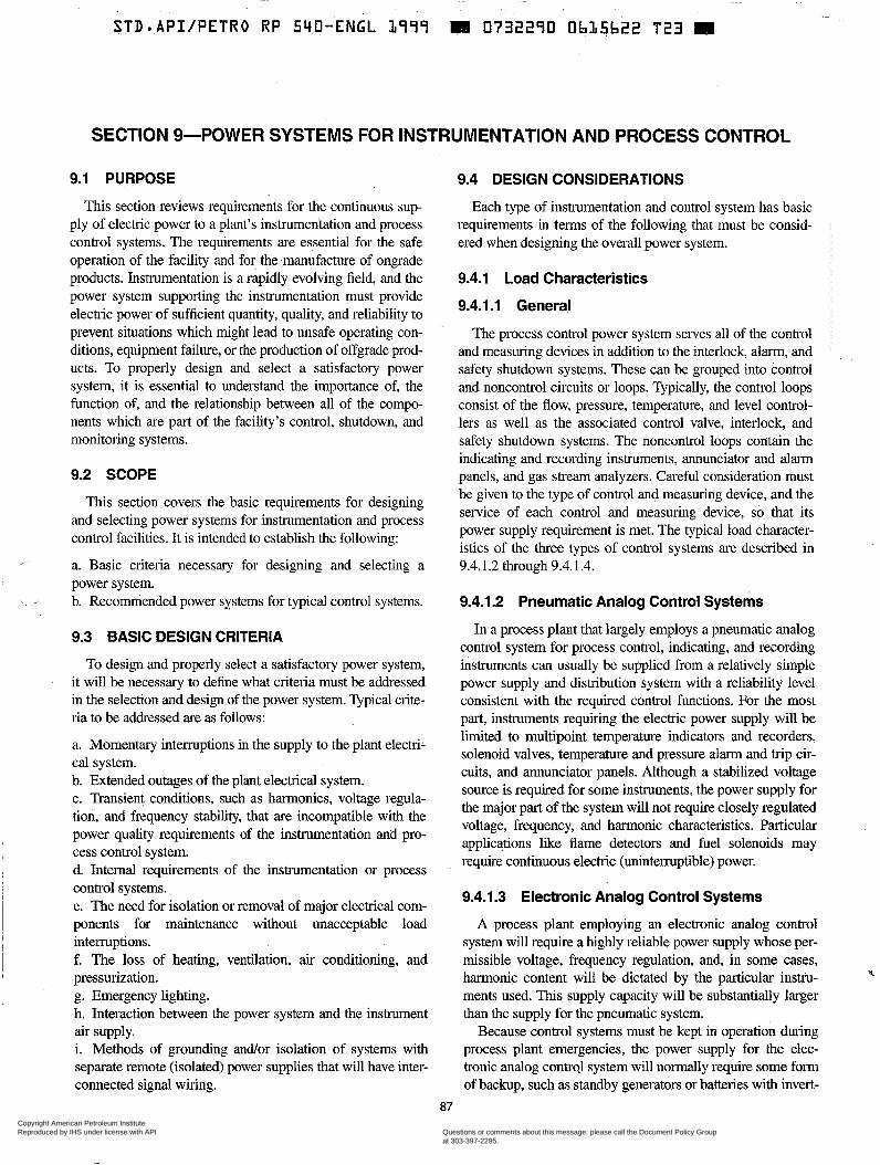
SECTION 9-POWER SYSTEMS FOR INSTRUMENTATION AND PROCESS CONTROL
9.1 PURPOSE
This section reviews requirements for the continuous sup- ply of electric power to a plant’s instrumentation and process control systems. The requirements are essential for the safe operation of the facility and for the manufacture of ongrade products. Instrumentation is a rapidly evolving field, and the power system supporting the instrumentation must provide electric power of sufficient quantity, quality, and reliability to prevent situations which might lead to unsafe operating con- ditions, equipment failure, or the production of offgrade prod- ucts. To properly design and select a satisfactory power system, it is essential to understand the importance of, the function of, and the relationship between all of the compo- nents which are part of the facility’s control, shutdown, and monitoring systems.
9.2 SCOPE
This section covers the basic requirements for designing and selecting power systems for instrumentation and process control facilities. It is intended to establish the following:
a. Basic criteria necessary for designing and selecting a power system. b. Recommended power systems for typical control systems.
9.3 BASIC DESIGN CRITERIA
To design and properly select a satisfactory power system, it will be necessary to define what criteria must be addressed in the selection and design of the power system. Typical crite- ria to be addressed are as follows:
a. Momentary interruptions in the supply to the plant electri- cal system. b. Extended outages of the plant electrical system. c. Transient conditions, such as harmonics, voltage regula- tion, and frequency stability, that are incompatible with the power quality requirements of the instrumentation and pro- cess control system. d. Internal requirements of the instrumentation or process control systems. e. The need for isolation or removal of major electrical com- ponents for maintenance without unacceptable load intermptions. f. The loss of heating, ventilation, air conditioning, and pressurization. g. Emergency lighting. h. Interaction between the power system and the instrument
i. Methods of grounding and/or isolation of systems with separate remote (isolated) power supplies that will have inter- connected signal wiring.
air supply.
9.4 DESIGN CONSIDERATIONS
Each type of instrumentation and control system has basic requirements in terms of the following that must be consid- ered when designing the overall power system.
9.4.1 Load Characteristics
9.4.1.1 General
The process control power system serves all of the control and measuring devices in addition to the interlock, alarm, and safety shutdown systems. These can be grouped into control and noncontrol circuits or loops. Typically, the control loops consist of the flow, pressure, temperature, and level control- lers as well as the associated control valve, interlock, and safety shutdown systems. The noncontrol loops contain the indicating and recording instruments, annunciator and alarm panels, and gas stream analyzers. Careful consideration must be given to the type of control and measuring device, and the service of each control and measuring device, so that its power supply requirement is met. The typical load character- istics of the three types of control systems are described in 9.4.1.2 through 9.4.1.4.
9.4.1.2 Pneumatic Analog Control Systems
In a process plant that largely employs a pneumatic analog control system for process control, indicating, and recording instruments can usually be supplied from a relatively simple power supply and distribution system with a reliability level consistent with the required control functions. For the most part, instruments requiring the electric power supply will be limited to multipoint temperature indicators and recorders, solenoid valves, temperature and pressure alarm and trip cir- cuits, and annunciator panels. Although a stabilized voltage source is required for some instruments, the power supply for the major part of the system will not require closely regulated voltage, frequency, and harmonic characteristics. Particular applications like flame detectors and fuel solenoids may require continuous electric (uninterruptible) power.
9.4.1.3 Electronic Analog Control Systems
A process plant employing an electronic analog control system will require a highly reliable power supply whose per- missible voltage, frequency regulation, and, in some cases, harmonic content will be dictated by the particular instru- ments used. This supply capacity will be substantially larger than the supply for the pneumatic system.
Because control systems must be kept in operation during process plant emergencies, the power supply for the elec- tronic analog contrd system will normally require some form of backup, such as standby generators or batteries with invert-
P
87
Copyright American Petroleum Institute Reproduced by IHS under license with API
Document provided by IHS Licensee=BG Group/5943895100, 01/31/2005 04:58:30 MSTQuestions or comments about this message: please call the Document Policy Groupat 303-397-2295.
--`,`,,,`,`,`,,,```,,``,,`,``,,-`-`,,`,,`,`,,`---
88 API RECOMMENDED PRACTICE 540
ers (if AC powered), or batteries (if the systems require DC only). The backup maintains a power supply to critical instru- ments and control circuits during total power failures which affect the normal electric power supply.
I
9.4.1.4 Digital Systems
Digital process control computers and microprocessor- based instrumentation are now widely used in direct control, supervisory, and monitoring functions. These systems can require power supply capacities ranging from 10 kVA to as much as 300 kVA in large plants. The electric power supply usually must meet closely regulated voltage, frequency, and hamonics limits for the connected load, and the purchased utility or plant generation supply usually requires some con- ditioning to meet the requirements of the load.
Digital control system power supplies are frequently pro- vided with two isolated, redundant, power input ports. The power supply sources should be separated as much as prac- tical from the facility main power source(s) to obtain maxi- mum reliability.
Uninterrupted power may be required to provide continu- ous control and monitoring during a power failure. The deci- sion to install an Unintermptible Power Supply (WS) should be based on the effects to the facility resulting from a power failure. Each manufacturer of the control and monitoring sys- tems will provide detailed power tolerakes and requirements for this equipment. Carehl consideration of these require- ments is essential to providing a proper electric power supply and distribution system.
9.4.2 Reliability Grading
9.4.2.1 General
Reliability grading can be keyed to the ability to operate during power supply interruptions. Economic design req@es that control loops be graded both with respect to reliability requirements under normal and emergency conditions and with respect to permissible voltage and frequency regulation and harmonic content limits.
Permissible interruption times are used to illustrate critical, semicritical, and noncritical loads, the three categories of loads requiring different degrees of power supply and distri- bution system reliability. Permissible interruption times, how- ever, will vary according to control equipment characteristics. For instance, it is possible that use of a delayed dropout provi- sion in a control loop may shift the control loop from a criti- cal to a semicritical category. The three categories of loads are described in 9.4.2.2 through 9.4.2.4.
9.4.2.2 Critical
A critical load is any load which cannot be intempted even momentarily or has a permissible interrupting time that may
be limited to a value such as 4 milliseconds (ms). To maintain a critical load, a power supply independent of normal plant power supply interruptions is required. AC loads are supplied typically from a rectifier-battery-inverter (UPS) combination while DC loads are supplied from a battery-supplied bus. In some cases, rotary no-break generators are used.
Transfer from normal to standby supply will require solid- state switches which have essentially zero switching time. Typical examples are flame scanners in boiler safety systems; fuel system solenoid shutdown valves; and centrifugal com- pressor shutdown circuits, if they are designed to shut down when de-energized.
9.4.2.3 Semicritical
A semicritical load is any load that must operate during emergency conditions but can operate satisfactorily through short interruptions. For a semicritical load, an independent power supply available during power failures is required.
A semicritical load may be broken down into a load for which interruptions up to 0.2 sec are permitted and a load for which interruptions as long as 20 sec may be permitted. The typical control loop is in the 0.2-sec group; the noncon- trol loop (temperature, indicator, and annunciator systems) is in the 20-sec group. Faster transfer from normal to standby supply, using electromechanical (contactor) switches with approximately a 100-ms switching time, is required for the 0.2-sec group; normal plant power supply delayed transfer until the start-up of the standby generators suffices for the 20-sec group.
9.4.2.4 Noncritical
A noncritical load is any load that may be dropped without affecting safe and orderly emergency operations. The power system during normal operating conditions must have a, high degree of reliability. Tank gauging systems and quality ana- lyzers are examples.
9.4.3 Quality Grading
‘Quality grading groups loads according to the stringency of the control devices’ requirements, ensuring that realistic and not excessive limits are placed on power supply fluctua- tions. Exact limits on supply fluctuations must be coordinated with each equipment supplier. Typical high quality limits are as follows:
a. For AC loads: l. Voltage regulation: 2 2%. 2. Frequency regulation: f 1 Hz for 50/60 Hz systems. 3. Total harmonic distortion: 3% maximum.
l. Voltage regulation: 1%. 2. Voltage ripple: 112% maximum.
b. For DC loads:
Copyright American Petroleum Institute Reproduced by IHS under license with API
Document provided by IHS Licensee=BG Group/5943895100, 01/31/2005 04:58:30 MSTQuestions or comments about this message: please call the Document Policy Groupat 303-397-2295.
--`,`,,,`,`,`,,,```,,``,,`,``,,-`-`,,`,,`,`,,`---
STD API/PETRO RP 540-ENGL L999 .073?27~0- 0.b15b2Y . .8Tb_.E-
ELECTRICAL INSTALLATIONS IN PETROLEUM PROCESSING PLANTS 89
9.5 ELECTRIC POWER SYSTEMS
9.5.1 General
The acceptability of the normal process plant power supply as the insuument supply will be determined by the reliability and quality requirements of the loads served. An independent power supply must be provided when the normal supply does not meet the load requirements. The length of time the partic- ular load must function during abnormal or emergency elec- tric power supply conditions must also be considered. Loads can be divided into categories that will determine the required capacity of the standby power supply. A supply period may be adequate for some loads; an 8-hr supply period may be adequate for others; and still others may require longer periods. Capacities for periods of 2 min to 3 hr are common for rectifier-battery-inverter (UPS) systems. When longer periods are required, or load requirements exceed 20 kVA, standby generators may be more economical.
9.5.2 Instrumentation and Control System Requirements
9.5.2.1 Pneumatic Analog Control Systems
Generally, the pneumatic analog control system can be sat- isfactorily supplied from the normal plant power system, assuming that this system has normal and alternate supplies that are reasonably independent of each other. This indepen- dence should be maintained in providing normal and alternate supplies to the main distribution bus of the process control power system. Where the plant has only a simple radial elec- trical distribution system, some provision for an alternate sup- ply to the process control system main bus should be made.
In all cases, particular attention must be paid to the require- ments of critical devices and circuits; examples of these criti- cal devices and circuits are boiler plant control, safety devices, and associated circuits; compressor control and shut- down circuits; and critical motor-operated valves which must function after a total power failure. Special provisions,. such as standby generator sets or rectifier-battery-inverter (UPS) combinations, may be required.
9.5.2.2 Electronic Analog and Digital Control Systems
The electronic analog control and digital computer moni- toring and control systems impose more stringent demands on the power supply. Independent normal and alternate sup- I
I plies to main AC and DC distribution buses are required. In I most plants, it will be necessary to provide an independent I
generation supply either in the form of a generator or a recti- fier-battery-inverter (UPS) combination. Where quality requirements are necessary, the independent generation sup- ply serves as the normal supply. Particular attention must be paid to determining to what extent the supply from the plant
power system can sewe as the alternate source. By applying the reliability and quality grading characteristics, the capacity and degree of redundancy that must be provided in indepen- dent generation can be held to an economic minimum. Impor- tant factors in supply sizing are the amount of in-rush current expected and the supply in-rush response characteristic. The memory and data preservation requirements, self-protection features, and limits of process computers also have a major effect on power supply requirements.
9.5.3 Typical Power Supplies
Special equipment design and application problems are encountered where automatic transfer or parallel operation of power supplies is used. There are many combinations of rotating and static generation power supplies and plant power supplies that may be used. The operating conditions which must be met and the unique characteristics of the combination which is selected should be understood thoroughly before a final design is established..
Typical one-line diagrams of power supplies are illustrated in Figures 19, 20, and 21. Each facility will require a unique design; however, the concepts noted in the following sections can be applied to most supplies.
9.5.3.1 Rectifier-Battery-Inverter System [such as an Uninterruptible Power Supply (UPS)]
Many features are available with the rectifier-battery- inverter system. When specifying the system, the following features should be considered:
a. The type of battery system, considering the ability to maintain and test the condition of the batteries. b. The ventilation of the batteries, if required. c. The ampere-hour (Ah) capacity of the battery bank. d. The seismic requirements for the battery rack. e. Rectifier input voltage, phase, and frequency. f. The required inverter output voltage, phase, and frequency. g. The inverter capacity, considering the largest load to be started, especially if it has high in-rush currents. h. The ambient temperature and humidity range in which the system will operate. Will the loss of heating, ventilation, and air conditioning be detrimental to the system? i. The space required to house the complete rectifier-battery- inverter system.
Some questions to consider when specifying the rectifier- battery-inverter system are as follows:
a. Where will the alternate supply originate? It should be a very reliable circuit(s) from the plant power system or another standby power supply. b. Will the inverter automatically return to the primary source after power is restored?
Copyright American Petroleum Institute Reproduced by IHS under license with API
Document provided by IHS Licensee=BG Group/5943895100, 01/31/2005 04:58:30 MSTQuestions or comments about this message: please call the Document Policy Groupat 303-397-2295.
--`,`,,,`,`,`,,,```,,``,,`,``,,-`-`,,`,,`,`,,`---
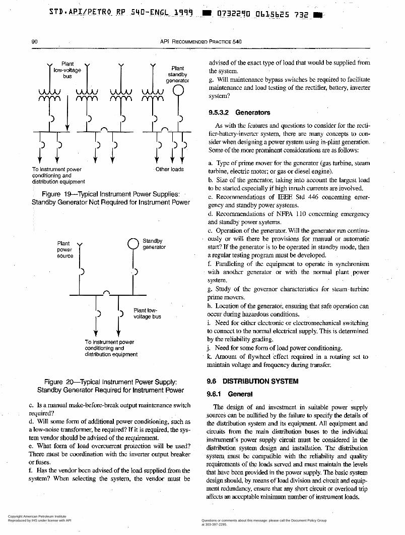
90 API RECOMMENDED PRACTICE 540
To instrument power conditioning and distribution equipment
Plant standby
generator
Other loads
Figure 19-Typical Instrument Power Supplies: Standby Generator Not Required for Instrument Power
I I Plant IOW- ( voltage bus
To instrument power conditioning and distribution equipment
Figure 20-Typical Instrument Power Supply: Standby Generator Required for instrument Power
c. Is a manual make-before-break output maintenance switch required? d. Will some form of additional power conditioning, such as a low-noise transformer, be required? If it is required, the sys- tem vendor should be advised of the requirement. e. What form of load overcurrent protection will be used? There must be coordination with the inverter output breaker or fuses. f. Has the vendor been advised of the load supplied from the system? When selecting the system, the vendor must be
advised of the exact type of load that would be supplied from the system. g. Will maintenance bypass switches be required to facilitate maintenance and load testing of the rectifier, battery, inverter system?
9.5.3.2 Generators
As with the features and questions to consider for the recti- fier-battery-inverter system, there are many concepts to con- sider when designing a power system using in-plant generation. '.
Some of the more prominent considerations are as follows:
a. Type of prime mover for the generator (gas turbine, steam turbine, electric motor; or gas or diesel engine). b. Size of the generator, taking into account the largest load to be started especially if high inrush currents are involved. c. Recommendations of IEEE Std 446 concerning emer- gency and standby power systems. d. Recommendations of NFF'A 110 concerning emergency and standby power systems. e. Operation of the generator. Will the generator run continu- ously or will there be provisions for manual or automatic start? If the generator is to be operated in standby mode, then a regular testing program must be developed. f. Paralleling of the equipment to operate in synchronism with another generator or with the normal plant power system. g. Study of the governor characteristics for steam turbine prime movers. h. Location of the generator, ensuring that safe operation can occur during hazardous conditions. i. Need for either electronic or electromechanical switching to connect to the normal electrical supply. This is determined by the reliability grading. j. Need for some form of load power conditioning. k. Amount of flywheel effect required in a rotating set to maintain voltage and frequency during transfer,
9.6 DISTRIBUTION SYSTEM
9.6.1 General
The design of and investment in suitable power supply sources can be nullified by the failure to specify the details of the distribution system and its equipment. All equipment and circuits from the main distribution buses to the individual instrument's power supply circuit must be considered in the distribution system design and installation. The distribution system must be compatible with the reliability and quality requirements of the loads served and must maintain the levels that have been provided in the power supply. The basic system design should, by means of load division and circuit and equip- ment redundancy, ensure that any short circuit or overload trip affects an acceptable minimum number of instrument loads.
Copyright American Petroleum Institute Reproduced by IHS under license with API
Document provided by IHS Licensee=BG Group/5943895100, 01/31/2005 04:58:30 MSTQuestions or comments about this message: please call the Document Policy Groupat 303-397-2295.
--`,`,,,`,`,`,,,```,,``,,`,``,,-`-`,,`,,`,`,,`---
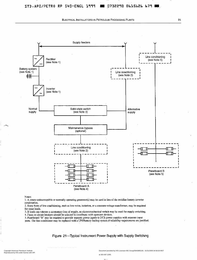
n
STD.API/PETRO RP SYO-ENGL L799 m 0732290 ObL5b2f b79 H
ELECTRICAL INSTALLATIONS IN PETROLEUM PROCESSING PLANTS 91
v Supply feeders v 4 t
"""""" I I I I Line conditioning I
I - - - - - - _ _ , _ _ _ -I Rectifier (see Note 1)
I (see Note 5) I
Battety system (see Note 1)
I""""-" I I Line conditioning I I (see Note 2) I I ""--""-I ~ l ~ l ~ l "
Inverter (see Note 1)
Normal Solid-state switch supply
Alternative (see Note 3) supply
Maintenance bypass (optional)
""""""""""
I I
I""""""""-
I I Line conditioning
I I
I (see Note 2) I I - f17] l o I " I
I -"J+ I I I I I I I I I ~ ~ - ~ ~ ~ ~ ~ " . ~ ~ ~ , ~ , , . l
Panelboard B (see Note 5)
Panelboard A (see Note 4)
Notes: 1. A rotary-unintermptible or normally operating generatods) may be used in lieu of the rectifier-battery-inverter combination. 2. Some form of line conditioning, such as low-noise, isolation, or a constant-voltage transformer, may be required for some loads. 3. If loads can tolerate a momentary loss of supply, an electromechanical switch may be used for supply switching. 4. Fuses or circuit breakers should be selected to coordinate with upstream devices. 5. Panelboard " B may be required to provide separate power inputs to DCS power supplies with separate input ports. The line conditioner may be replaced with a Upsbattery backup system if reliability requirements are justified.
Figure 21-Typical Instrument Power Supply with Supply Switching
Copyright American Petroleum Institute Reproduced by IHS under license with API
Document provided by IHS Licensee=BG Group/5943895100, 01/31/2005 04:58:30 MSTQuestions or comments about this message: please call the Document Policy Groupat 303-397-2295.
--`,`,,,`,`,`,,,```,,``,,`,``,,-`-`,,`,,`,`,,`---
- . . . .
92 API RECOMMENDED PRACTICE 540
9.6.2 Design Requirements
Requirements for the following components must be speci- fied in the distribution system design:
a. Feeders from the supply sources to the main instrument power panelboàrd. b. Feeders to main load panelboards, branch panelboards, and instrument and control panels. c. Panelboards, including circuit breakers and fuses. The fuses may be required to coordinate with the upstream devices (see Figure 21). To avoid transfer-to-bypass and possible voltage depression during faults, Classes CC or J fuses, with as low an ampere rating as possible to serve the load, are recommended for the distribution panel branch circuit overcurrent protection.
Note: This will allow the U P S source to clear the fault rather than transferring to bypass to clear the fault.
d. Transfer switches.
9.6.3 Criteria for System Design
The following are some criteria for system design:
a. Normal and alternate feeders to distribution panelboards should be provided as required by reliability requirements. b. Particular attention should be given to distribution panel- board load assignments. The loads on each process unit or major process section should be split so that a distribution bus failure cannot affect all of the control loops. c. Main and important branch panelboards should have at least two separated or isolated bus sections, or separate panel- 'boards should be used. d. Circuit protection and disconnect means for each control loop supply should be provided. e. All overcurrent and short-circuit protective devices should be coordinated so that the device closest to fault opens first. f. The system should be able to transfer between sources without loss of supply. g. Individual pieces of equipment should be redundant to lessen the probability of a total system failure.
9.7 WIRING METHODS
9.7.1 General
The actual circuit requirements for individual instruments will be determined by the type of instrument being served, and are a part of the instrument system design.
9.7.2 Power Wiring
Power supply and distribution system wiring for instru- ment and control system power shall comply with NFPA 70. Section 8 of this recommended practice should also be con- sulted for the various types of applicable power wiring used in petroleum processing plants.
9.7.3 Special Considerations
Wiring methods which are acceptable for power wiring may be used. Attention must be paid to special requirements which are a result of the circuit function. For instance, special atten- tion should be paid to the routing of safety control and shut- down circuits. These circuits should be segregated from normal circuit mutes to prevent a single accident from disabling both circuits. Fireproofing of exposed components of these circuits and use of wire insulation rated for high temperature may be necessary to preserve the circuit integrity for a specified time period during a fire. To facilitate the fast clearing of branch cir- cuit faults by current-limiting fuses, the branch circuit wiring may need to be oversized to reduce the total circuit resistance (and subsequently increase the fault current available to make the fuses operate in their current-limiting region).
9.8 SYSTEM AND EQUIPMENT GROUNDING P.
Normal system and equipment grounding must be supple- mented and modified by any special requirements imposed by the instrument and computer loads. Manufacturers of distrib- uted control system computers and programmable controllers supply facilities' requirement manuals which may specify any special requirements for their equipment. Electrical safety is essential in the power system grounding design; therefore, the requirements of NFPA 70 for grounding must be satisfied. (Sec- tion 5 provides information on specific grounding practices in process plants.) The grounding of a power system for a distrib- uted control system requires careful planning from the start of a project. A detailed grounding diagram should be developed for each project and reviewed with all of the equipment vendors.
9.9 CONSIDERATIONS FOR CLASSIFIED LOCATIONS
Equipment application and wiring methods for the power supply source and distribution system must comply with NFPA 70 requirements applicable to the particular classified location. Generally, this equipment and wiring will operate at energy levels which can cause ignition.
Copyright American Petroleum Institute Reproduced by IHS under license with API
Document provided by IHS Licensee=BG Group/5943895100, 01/31/2005 04:58:30 MSTQuestions or comments about this message: please call the Document Policy Groupat 303-397-2295.
--`,`,,,`,`,`,,,```,,``,,`,``,,-`-`,,`,,`,`,,`---
~ ~
STD.API/PETRO RP 540-ENGL 1779 I 0732290 ObIt5b28 44% H.
SECTION IO-SPECIAL EQUIPMENT
10.1 PURPOSE have elected to furnish or lease their own instruments, switch-
This section covers special electrical equipment and instal- lations encountered in a processing plant that are not covered in other sections of this publication.
10.2 SCOPE
This section is limited to a brief description of such instal- lations. The need for or the extent of such installations is not defined in this section.
10.3 GENERAL
Many systems and pieces of equipment in a processing plant need electrical service that is somewhat different or has requirements other than those generally provided for by the usual power and lighting service. These include communica- tion and signaling systems, Supervisory Control And Data Acquisition (SCADA) Systems, special lighting systems, and heat tracing. Consideration must be given to the special requirements of this equipment.
10.4 COMMUNICATION SYSTEMS
10.4.1 Radio Systems
Fixed radio equipment is used extensively in processing plants for communication between other fixed equipment, portable equipment, and mobile equipment. The fixed equip- ment is typically located in operation or maintenance centers and is used for dispatching, security, and process-unit com- munication.
Portable radio equipment is available in two forms, the hand-held, two-way communication device and the belt- mounted, call-pager system. The call-pager unit alerts its carrier, who, in turn, uses a telephone to communicate with the caller. Some call-pager units allow a more detailed mes- saging capability. Portable radio equipment that will be used in classified locations must be approved for use in such locations.
Mobile radio equipment is provided in vehicles used for deliveries, maintenance, security, and fire protection, and is also provided in vehicles used by facility management. , 10.4.2 Telephone Systems
Most processing plants are served by the local telephone utility, which may furnish and install all wire, cable, terminal blocks, instruments, switchboards, batteries, battery chargers, and other miscellaneous equipment. It is the responsibility of the processing plant to furnish and install all conduit and junction boxes for the system. In recent years, many facilities
boards, and connecting equipment. Telephone instruments used in Division 1 locations must
be of explosionproof construction. In Division 2 locations, standard telephones which have been tested and approved for Division 2 locations or telephones of explosionproof con- struction may be used. In nonclassified locations, instruments of standard construction may be used.
Telephone switching equipment is usually located in a tele- phone room in an office or other service building outside the process area. Distribution of telephone circuits within build- ings is usually accomplished with multiconductor cables in conduit or underfloor ducts; or with plastic-sheathed cables in ceiling spaces and walls. Outdoors, the telephone hstribution system may consist of multiconductor cable in conduit or underground ducts, direct burial cable, or aerial cable attached to poles carrying power and lighting feeders. Wiring methods must be suitable for the electrical area classification. Corrosion protection requirements, and reliability require- ments should also be considered in selecting wiring methods.
Sound-powered telephones are used on operating units and in other classified areas. The instruments are voice-operated and require no electric power to operate. Associated with these sound-powered telephones is usually some type of sig- naling system which requires electric power. The voice and signaling system should not be installed in the same raceway unless the signaling circuit is intrinsically safe.
Bells, horns, howlers, and relays associated with communi- cation equipment must be suitable for the electrical area clas- sification in which they are installed.
10.4.3 Public Address Systems
Public address systems are commonly used for public address purposes as well as for paging plant personnel in pro- cess units. In some cases, they are used for addressing and paging entire plants. They are often used in conjunction with sirens or howlers to convey emergency warning information to plant personnel. Caution should be exercised in applying this type of equipment in classified areas (see N”A 70).
10.5 SUPERVISORY CONTROL AND DATA ACQUISITION EQUIPMENT (SCADA)
Supervisory control and data acquisition (SCADA) equip- ment may be used for monitoring and controlling plant utility systems (e.g., electrical, cooling water, and steam systems). The user interface for this equipment is usually located in an operations control center. Through this equipment, circuit breaker positions (open or closed), pump status (running or not running), system parameters (e.g.. flow, pressure, and
93
Copyright American Petroleum Institute Reproduced by IHS under license with API
Document provided by IHS Licensee=BG Group/5943895100, 01/31/2005 04:58:30 MSTQuestions or comments about this message: please call the Document Policy Groupat 303-397-2295.
--`,`,,,`,`,`,,,```,,``,,`,``,,-`-`,,`,,`,`,,`---
94 API RECOMMENDED PRACTICE 540
load), and substation building pressurization systems can be monitored and controlled remotely.
10.6 CLOSED-CIRCUIT TELEVISION (CCTV)
Applications for closed-circuit television are numerous. Monitoring of process control boards and metering, as well as monitoring flare, boiler, and furnace flame patterns, is com- mon. The largest application of television equipment in pro- cess facilities, however, is for security. In this application, it is used for monitoring operations at personnel, vehicle, and rail- road gates, warehouses and storage areas. Video recording equipment is often used in conjunction with the CCTV sys- tem when historical records are required.
10.7 OBSTRUCTION AND WARNING LIGHTING
For tall structures and stacks, special obstruction or warn- ing lights may be required by the Federal Aviation Adminis- tration or other authority having jurisdiction.
10.8 NAVIGATION LIGHTING
Piers and similar structures extending into navigable waters must be furnished with obstruction lighting as required by regulations of the US. Coast Guard or other authority having jurisdiction.
10.9 FIRE ALARM SYSTEMS
A fire alarm system is normally maintained within a pro- cessing plant. Some systems are elaborate while others are relatively simple. API RP 2001 discusses fire alarm require- ments, and the NFPA Fire Protection Handbook discusses alarm facilities.
10.10 ELECTRIC HEATTRACING
Electric-heat tracing systems are used for maintaining pro- cess piping or vessel temperatures and for freeze prevention. Electric heat tracing is used in lieu of steam-heat tracing where it is determined to be more economical or where pre- cise temperature control is required.
Several types of electric heat tracing systems are avail- able. These include electrical-resistance heat tracing as well as impedance, induction, and skin effect systems. Electrical- resistance heat tracing is typically used for applications on process units. Impedance, induction, or skin-effect electric heat tracing is typically applied on long pipelines to offsite locations or between. facilities. IEEE Std 515 provides design guidance for electrical-resistance heat tracing sys- tems. IEEE 844 provides similar guidance for impedance, induction, and skin effect systems.
Electric-heat tracing systems are typically powered from field distribution panelboards fed from dry-type transformers. Each panelboard circuit is used, within its capacity, to serve a
continuous section of piping, associated valves and, if required, process instrumentation. Power circuit conductors must be suit- able for the temperatures to which they will be exposed.
System disconnect and grounding arrangements should meet NEC Article 427 requirements. For electrical-resis- tance-type heat tracing systems, this includes a requirement that all heat-tracing circuits be provided with either ground fault protection or, for industhl establishments, an alarm indication of a ground fault.
All components of electric-heat tracing systems must be suitable for the area classification in which they will be installed.
10.1 1 CATHODIC PROTECTION SYSTEMS
Cathodic protection systems are used to provide corrosion protection for underground piping, tanks, or other metal structures that are in contact with the earth, and offshore facil- ities. Cathodic protection systems are either sacrificial anode or impressed current type. Cathodic protection surveys are typically performed to determine the type of system to be used.
Sacrificial anode systems do not require a power source. Impressed current systems require a DC power source that is supplied from a field transformer/rectifier assembly. Amme- ters are often provided to allow monitoring of the current flow in impressed current circuits.
Design guidance for cathodic protection systems is pro- vided by API RP 65 l and NACE RP 0169. In the design of cathodic protection systems, consideration must be given to the adverse impact that such systems may have on any nearby electrical-grounding grid systems. For offshore installations, design guidance is given by NACE RP 0176 and NACE RP 0675.
Cathodic protection system components must be suitable for the area classification in which they are installed. 'Trans- former/rectifier assemblies that are installed in classified loca- tions are often designed to be oil-immersed.
10.12 DESALTERS AND PRECIPITATORS
10.12.1 Electrostatic desalters are used to reduce the salt and solids contents of crude oils. This reduces fouling and cor- rosion resulting from salt deposition on heat transfer surfaces, and acids formed by decomposition of the chloride salts. Typi- cal solids which are removed from the crude oil include fine sand, clay and soil particles, iron oxide, and other contami- nants which can be picked up during crude oil production and transportation. The desalting process can also improve catalyst life in downstream processes by partially rejecting certain metals that can cause catalyst deactivation.
Desalting is performed by mixing crude oil with water at temperatúres from 90°C to 150°C. The salts are dissolved in the wash water and the oil and water phases are then sepa- rated in a settling vessel. A high-potential electrical field is
Copyright American Petroleum Institute Reproduced by IHS under license with API
Document provided by IHS Licensee=BG Group/5943895100, 01/31/2005 04:58:30 MSTQuestions or comments about this message: please call the Document Policy Groupat 303-397-2295.
--`,`,,,`,`,`,,,```,,``,,`,``,,-`-`,,`,,`,`,,`---
STD-API/PETRO RP -540-ENGL lSq9 m O73ZZ=lO _OblSb30 OTT I
ELECTRICAL lNSTALLATlONS IN PETROLEUM PROCESSING PLANTS 95
applied across the settling vessel to facilitate the coalescing of the salt water droplets. Either AC or DC fields may be used, with potentials ranging from 16,000 V to 35,000 V. Energy consumption is typically 0.05 kWh to O. 15 kWh per barrel of feed.
In some cases, both AC and DC fields are used to provide high dewatering efficiency. The AC field is applied near the oivwater interface; and the DC field in the oil phase is applied above the interface. Efficiencies of up to 99% water removal in a single stage are claimed for the dual-field process. The dual-field electrostatic process provides efficient water sepa- ration at lower temperatures, resulting in a higher overall energy efficiency than for single field designs.
10.1 2.2 Electrostatic precipitators are used to remove solid particles from flue gas air streams an application of a DC field. Typically, precipitators are located in power plants, incinerators, and fluid catalytic cracking units.
10.1 3 PORTABLE EQUIPMENT
Much of the portable or mobile equipment used in process- ing plants requires electric power. Some examples of portable equipment requiring electric power are as follows:
a. Welding machines. b. Motor-driven portable pumps. c. Motor-driven poltable compressors. d. Power tools. e. Extension and hand lamps. f. Annealing machines. g. Test instruments. h. Tool trailers. i. Storehouse trailers. j. Office trailers. k. Meter testing rigs.
This equipment operates at 600 V or less, single-phase or three-phase as required. Permanent receptacles are installed when periodic'use of portable equipment justifies the installa- tion. Otherwise, temporary wiring is used for supplying power. Particular attention should be given to grounding por- table equipment for personnel protection. (Section 5 provides further discussion of this subject.)
Copyright American Petroleum Institute Reproduced by IHS under license with API
Document provided by IHS Licensee=BG Group/5943895100, 01/31/2005 04:58:30 MSTQuestions or comments about this message: please call the Document Policy Groupat 303-397-2295.
--`,`,,,`,`,`,,,```,,``,,`,``,,-`-`,,`,,`,`,,`---
~~
. .
STD.API/PETRO ~ RP SL10-ENGL L999 m 0732290 ObLSb3L T36 II
SECTION Il-INHERENT ELECTRICAL SAFETY
11.1 GENERAL related maintenance requirements.
11.1.1 The electrical engineer who intends to take advan- tage of incorporating electrical safety by design in his work needs first to obtain knowledge about the requirements for working safely in an atmosphere influenced by the presence of electricity.
11.1.2 The principal hazards of working around electrical equipment are electrical shock and electrical arc flash. While
close that the intervening air gap breaks down and becomes conductive, the electrical arc flash hazard can extend a con- siderable distance from the exposed energized electrical con- ductor or circuit part.
11.1.3 The most effective protection against electrical haz- ards can be achieved by distance andor by enclosure. Where exposed energized electrical conductors or circuit parts are present, the assigned employee must possess knowledge of, and must employ, electrical safe work practices.
11.2 REFERENCES
11.2.1 The principal sources of guidance for electrical safe work practices and safe electrical facilities are:
I an electrical shock hazard involves contact, or approach so
~
~ 11 .2.1.1 OSHA 29 CFR 1910
a. Subpart I-Personal Protective Equipment 1910.137-E1ectrica1 protective equipment.
b. Subpart J-General Environmental Controls 1910.145-Specifications for accident prevention signs and tags. 1910.147-The control of hazardous energy (lockout tagout).
c. Subpart R-Special Industries 1910.269-Electrical power generation, transmission and distribution.
1910.301-“Introduction’~-This subpart addresses elec- d. Subpart S-Electrical
1910.381 through 1910.398-Reserved for future safety requirements for special equipment. 1910.399-Definitions applicable to each division.
11.2.1.2 OSHA 29 CFR 1926
Subpart K-Electrical Standards for Construction
11 2.1.3 NFPA 70 National Electrical Code
The National Electrical Code deals primarily with the minimum design and installation requirements for electrical equipment. OSHA has determined that electrical facilities installed in accordance with the NEC are safe until the equip- ment is compromised by deterioration, or until an unsafe act or a combination of unsafe acts occur.
11.2.1.4 NFPA 70E Electrical Safety Requirements for the Employee Workplace
This document deals primarily with the minimum require- ments for protecting employees working in and around elec- trical equipment. OSHA recognizes the benefits of a consensus standard for safe work practices in general industry and has encouraged the NFPA to pursue the full development of NFPA 70E. NFPA 70E attempts to develop specifics by which OSHA performance statements in Subpart S can be accomplished.
11.2.1.5 ANSIAEEE C2 National Electrical Safety Code
The National Electrical Safety Code deals primarily with the minimum design, installation, and maintenance require- ments related to overhead power lines, control and telecom- munications installations. OSHA recognizes the benefits of a consensus standard for safe work practices in special indus- tries and has encouraged the EEE to pursue regular revisions of ANSIAEEE C2. ANSVIEEE C2 attempts to develop specif- ics by which OSHA performance statements in Subpart R can be measured.
trical safety requirements that are necessary for the practical .3 SPECIFICS safeguarding of employees in their workplaces.
Sections 1910.302 through 1910.399 contain five major 11.3.1 Distance from potential sources of exposed ener- divisions: gized electrical conductors and circuit parts can be achieved
: by various means. Qualified persons are permitted to 1910’302 through 1910*330”Contain safety approach much closer than are unqualified persons. Qualified dards for electrical systems. persons by OSHA definition are “Ones familiar with the con-
electrical hazards involved with the work being performed.”
I I 1910’302 &Ough 1910’308rontain safety struction and operation of the electrical equipment and the I dards for electric utilization systems.
1910.309 through 1910.330-Reserved for possible future use for design safety standards for other electrical systems. 11.3.1 -1 Unqualified persons around voltages to ground 1910.331. through 1910.360-Contain safety-related of 50 kV or less must maintain a distance of 305 cm (10 ft). work practices. For voltages to ground over 50 kv, use 305 cm (10 ft) plus 1910.361 through 1910.38O”Reserved for future safety- 10 cm (4 in.) for every k v over 50 kv.
97
Copyright American Petroleum Institute Reproduced by IHS under license with API
Document provided by IHS Licensee=BG Group/5943895100, 01/31/2005 04:58:30 MSTQuestions or comments about this message: please call the Document Policy Groupat 303-397-2295.
--`,`,,,`,`,`,,,```,,``,,`,``,,-`-`,,`,,`,`,,`---
98 API RECOMMENDED PRACTICE 540
11.3.1.2 Qualified persons must not approach closer than the distances shown in Subpart S, Table S-5.
11.3.1.3 Examples of distance are: the clear working space requirements of Subpart S, Table S-1; that to be achieved by use of control room breaker operation for remotely opening or closing switching devices; that achieved by use of mimic bus with control switches located remote from the front of metal enclosed or metal clad switchgear; or that to be achieved by use of umbilical cords having control switches for opening or closing the switching device on the far end.
11.3.2 Enclosures have varying degrees of integrity. The enclosures' principal functions are to protect the electrical
conductors or circuit parts from the elements and from physi- cal damage, as well as to isolate the electrical conductors and circuit parts from people. Deterioration of enclosures by cor- rosion, neglect, or mechanical damage can lead to exposure of electrical conductors or circuit parts.
11.3.2.1 Examples of enclosure-when' properly applied and maintained can be counted on to contain the explosive force of an electrical arc or divert its effect in an innocuous direction-are: explosionproof enclosures that contain the explosive forces; or those of arc-resistant construction that direct the energy of the explosion through specially designed vents in the top or ends of the equipment to nonoc- cupied locations.
Copyright American Petroleum Institute Reproduced by IHS under license with API
Document provided by IHS Licensee=BG Group/5943895100, 01/31/2005 04:58:30 MSTQuestions or comments about this message: please call the Document Policy Groupat 303-397-2295.
--`,`,,,`,`,`,,,```,,``,,`,``,,-`-`,,`,,`,`,,`---
ST$.API/PETRO RP 540-ENGL.Lq99 I 0732290 ObL5b33 4 0 q . m .
APPENDIX A-INFORMATIVE INHERENT SAFETY CONSIDERATIONS
Appendix A is intended to provide additional items that may need to be addressed in the safe application of elecbical equipment into petroleum processing facilities: A suggested approach is to use these items as discussion topics when defining the design scope with the project team. Communica- tion between the user, Engineering & Construction Service (E&CS), and vendor is strongly urged to evaluate the desir- ability, capability and necessity of each item. It is recognized that no design could or would incorporate all of these items.
A.l Switchgear and Motor Control Centers
Consider using the following features in the design:
a. Arc Resistant Switchgear for all metal-clad applications. b. Use of current-limiting fuses for all 480 V and 600 V devices. c. Equipment selection and sizing to minimize/reduce flash protection boundary. d. Remote close/open of switchgear breakers. e. Remote racking-in of switchgear breakers. f. Secondary selective switchgear systems: Use of a second tie-breaker in series with the tie-breaker to ensure complete de-energization and isolation. g. Secondary selective switchgear systems: Use of a second tie-breaker in parallel with the tie-breaker to facilitate on-line testing of the secondary selective system operation. h. Local back-up trip provisions only of breakers normally closedopened from a remote location. i. CT shorting terminals to be located near relay wiring ter- minals for quicweasy access and shorting; and automatic shorting provisions whenever relays with current inputs are removed. j. Use of insulated buses and bus ends in bus ducts, switch- gear, motor control center, and switchracks. k. Use of “finger safe” fuse-holders: the fuses are contained in a removable carrier with markable labels. Finger safe is defined as where live parts are inaccessible whether fuse is in, or out, or in-between. 1. Use of finger safe terminals in 120/208/240 V power pan- els, relay control panels, DCSPLC control systems, metering and instrument panels, control room termination panels, etc. m. Use of equipment with “built-in” transducers. n. Use of “encapsulated” equipment. o. Lockable, hinged-type rear doors at switchgear breakers. p. Lockable front doors at switchgear breakers where it is unfeasible to place a lock on the switchgear breakers.
q. Provision to padlock all energy isolating devices, includ- ing fuse blocks in off-position. r. Use of voltage-rated boots over switchgear bus joints in place of electrical taping to facilitate maintenance. s. Use of “transparent inspection windows” in switchgesu; switches, motor control centers, and transformers to allow inspection or monitoring of required components and functions. t. Use of CT secondary, open-circuit protectors. u. Segregation of electrical components with different volt- ages in common enclosures, cabinets, etc. v. Moisture inhibitors in switchgear, instruments, junction boxes, enclosures, etc. W. Interlocking of primary and secondary breakers of a power transformer to prevent back-feed through the transformer. x. Provisions to manually trip breakers (on loss of trip power) without requiring the opening of the enclosure doors. y. Interlocking to prevent any unden-ating because of system configuration, or out-of-synch closures at locations where synch check relays are not provided and an out-of-synch con- dition can occur. z. Interlocking of all isolating switches (with no or inade- quate interrupting rating) with interrupting devices suitable for fault interruption to ensure de-energized operation. aa. Interlocking to prevent access to live parts. bb. Interlocking to prevent closing of breakers or starters if trip power is not available. cc. Indication of overload trips on all motor starters. dd. Covers for all terminals containing potential sources 50 V and above. ee. Utilization of single-phase relays to prevent failure of breaker tripping because of three-phase relay failure at the time of a fault. ff. Utilization of lock-out relays to prevent closing of break- ers/starters after a protective device operation. gg. Utilization of single-phase relays vs three-phase relays to allow safe testing and calibration of relays while the equip- ment is energized. hh. Utilization of independent current transformers and cir- cuitdwiring for primary and back-up relaying. ii. Installation of surface mounted flexitest switches on the switchgear to prevent relay trips during testing (blades of sur- face-mounted switches shall not be energized when open). jj. Conveying all critical alarms to an attended location or control room.
99
Copyright American Petroleum Institute Reproduced by IHS under license with API
Document provided by IHS Licensee=BG Group/5943895100, 01/31/2005 04:58:30 MSTQuestions or comments about this message: please call the Document Policy Groupat 303-397-2295.
--`,`,,,`,`,`,,,```,,``,,`,``,,-`-`,,`,,`,`,,`---
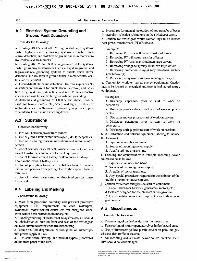
1 O0 API RECOMMENDED PRACTICE 540
A.2 Electrical System Grounding and e. Procedures for manual restoration of and transfer of buses Ground Fault Detection in secondary selective substations on the switchgesu. doors.
f. Caution for switchgear work caution tags to be located Consider the following: near power transformers (PTs)/fuses/etc.
a. Existing 480 V and 600 V ungrounded wye systems: Install high-resistance grounding systems to enable quick alarm, detection, and isolation of ground faults in motor con- trol centers and switchracks. b. Existing 480 V and 600 V ungrounded delta systems: Install grounding transfomers to create a system ground, and high-resistance grounding systems to enable quick alarm, detection, and isolation of ground faults in motor control cen- ters and switchracks. c. Ground-fault alarm and detection: Use zero sequence CTs in starters and breakers for quick alam, detection, and isola- tion of ground faults in 480 V and 600 V motor control centers and switchracks with high-resistance grounding. .
d. Auto/manual grounding of 1,000 V and above, feeders, capacitor banks, motors, etc., when switchgear breakers or motor starten are withdrawn. If grounding is provided, pro- vide interlock with main switching device.
A.3 Substations Consider the following:
a. Fire wall between power transformers. b. Use of ground fault circuit interrupter (GFCI) receptacles. c. Use of insulating mats in substations and motor control centers. d. Use of concrete or metal post barriers around outdoor pad- mount transformers and other electrical equipment. e. Use of toe-wall around battery bank to contain battery liquid in the event of battery leaks. f. Use of plexiglass barrier at the battery bank to prevent unqualified persons from getting close to the exposed battery terminals. g. Use of on-line monitoring of dissolved gas in trans- former oil.
A.4 Labeling and Marking Consider the following:
a. Mark flash protection boundary and personal protective equipment (PPE) requirements on each switchgear, switchrack, motor control center, etc. for energized work, work within flash protection boundary, etc. b. Labelinglmarking of instrument relaydmeters, all should be labeledmarked both on front and rear of the switchgear doors to eliminate errors when troubleshooting. c. Mimic one-line diagram on the front panel of uninterrupt- ible power supply (UPS). d. UPS shut-down, start-up, and manual-bypass procedures on the front panel of the UPS.
Examples: 1. Removing PT fuses will cause transfer of buses. 2. Removing PT will cause transfer of buses. 3. Removing PT fuses may shutdown large drivers. 4. Removing voltage relay may shutdown large driver. 5. Removing protection relay(s) may shutdown switch- gear breaker(s). 6. Removing relay may shutdown switchgear bus, etc.
g. Caution for work on stored energy equipment: Caution tags to be located on electrical and mechanical stored energy equipment.
Examples: 1. Discharge capacitors prior to start of work .on capacitors. 2. Discharge power cables prior to start of work on power cables. 3. Discharge motors prior to start of work on motors. 4. Discharge generators prior to start of work on generators. 5: Discharge springs prior to start of work on breakers.
h. All substation and outdoor equipment labeling to include the following:
l. Equipment number and name. 2. Source of incoming power supply. 3. AreaAist of power users, etc.
i. Labeling for equipment with multiple incoming power sources to be as follows:
l. Equipment number and name. 2. Sources of incoming power supply. 3. AreaAist of power users, etc. 4. Any special procedures required for the isolation of the multiple incoming power sources.
1. Label switchgear breakers, generators, motors, etc.; if these are designed for remote start or energization. 2. Use of audible signals at equipment prior to their ener- gizatiodstart.
j. Caution-for remote energizatiodstart of equipment:
A.5 Miscellaneous
Consider the following:
a. Fireproofing of cables/conduits in fire hazard area. b. Fireproofing of motor-operated valves in fire hazard area. c. Use of fluorescent yellow plastic covers on pole line guy wires to alert traffic in the area. d. All incoming and àlternate power source breakers for a UPS should be lockable type.
Copyright American Petroleum Institute Reproduced by IHS under license with API
Document provided by IHS Licensee=BG Group/5943895100, 01/31/2005 04:58:30 MSTQuestions or comments about this message: please call the Document Policy Groupat 303-397-2295.
--`,`,,,`,`,`,,,```,,``,,`,``,,-`-`,,`,,`,`,,`---
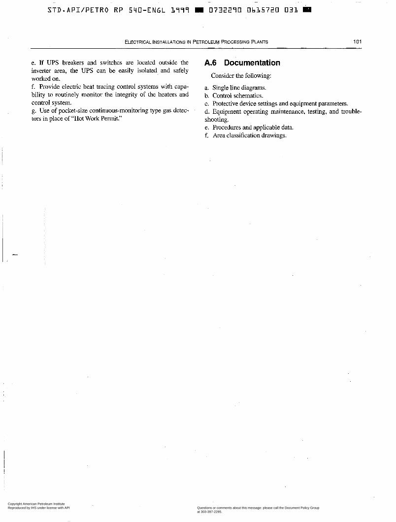
STD.API/PETRO RP 59O-ENGL 1777 W 0732290 Ob15720 O31 B
ELECTRICAL INSTALLATIONS IN PETROLEUM PROCESSING PLANTS 1 o1
e. If UPS breakers and switches are located outside the inverter area, the UPS can be easily isolated and safely worked on. f. Provide electric heat tracing control systems with capa- bility to routinely monitor the integrity of the heaters and control system. g. Use of pocket-size continuous-monitoring type gas detec- tors in place of “Hot Work Permit.”
A.6 Documentation Consider the following:
a. Single line diagrams. b. Control schematics. c. Protective device settings and equipment parameters. d. Equipment operating maintenance, testing, and trouble- shooting. e. Procedures and applicable data. f. Area classification drawings.
Copyright American Petroleum Institute Reproduced by IHS under license with API
Document provided by IHS Licensee=BG Group/5943895100, 01/31/2005 04:58:30 MSTQuestions or comments about this message: please call the Document Policy Groupat 303-397-2295.
--`,`,,,`,`,`,,,```,,``,,`,``,,-`-`,,`,,`,`,,`---

The American Petroleum Institute provides additional resources and programs to industry which are based on API Standards. For more mformation, contact:
Training and Seminars Ph: 202-682-8490 Fax: 202-682-8222
Inspector Cedication Programs Ph: 202-682-8161 Fax: 202-962-4739
American Petroleum Institute Ph: 202-962-4791 Quality Registrar Fax: 202-682-8070
Monogram Licensing Program Ph: 202-962-4791 Fa: 202-682-8070
Engine Oil Licensing and Ph: 202-682-8233 Certification System Fax: 202-962-4739
Petroleum Test Laboratory Ph: 202-682-8064 Accreditation Program Fax: 202-962-4739
In addition, petroleum industry technical, patent, and business information is available online through API EnCornpass”. Call 212-366-4040 or f a x 212-366-4298 to discover more.
To obtain a free copy of the API American Publications, Programs, and Services Petroleum Catalog, call 202-682-8375 or f a x your Institute request to 202-962-4776. Or see the o h e interactive version of the catalog ... ’I Helping You
on our World Wide Web site - Get The Job Done Right.
http://www.api.org.
Copyright American Petroleum Institute Reproduced by IHS under license with API
Document provided by IHS Licensee=BG Group/5943895100, 01/31/2005 04:58:30 MSTQuestions or comments about this message: please call the Document Policy Groupat 303-397-2295.
--`,`,,,`,`,`,,,```,,``,,`,``,,-`-`,,`,,`,`,,`---
STD.API/PETRO RP 540-ENGL L999 m 0732290 0bL5722 904
Additional copies available from API Publications and Distribution:
Information about API Publications, Programs and Services is available on the World Wide Web at: http://www.api.org
(202) 682-8375
American 1220 L Street, Northwest Petroleum Washington, D.C. 20005-4070
Institute 202-682-8000 Order No. C54004
Copyright American Petroleum Institute Reproduced by IHS under license with API
Document provided by IHS Licensee=BG Group/5943895100, 01/31/2005 04:58:30 MSTQuestions or comments about this message: please call the Document Policy Groupat 303-397-2295.
--`,`,,,`,`,`,,,```,,``,,`,``,,-`-`,,`,,`,`,,`---


![Untitled-1 []...Sponsorship Dana Usaha A cara Sponsorship Perlengkapan Pubdok Medis Keamanan Konsumsi BPH Rp. Rp. Rp. Rp. Rp Rp Rp Rp Rp Rp Rp Rp Rp. 4000.000,00 ...](https://static.fdocuments.net/doc/165x107/61443310aa0cd638b460b395/untitled-1-sponsorship-dana-usaha-a-cara-sponsorship-perlengkapan-pubdok.jpg)