APEX SERIES 5000 BILL ACCEPTOR - VendService · APEX SERIES 5000 BILL ACCEPTOR...
37
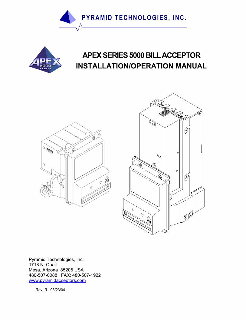
PYRAMID TECHNOLOGIES, INC. APEX SERIES 5000 BILL ACCEPTOR INSTALLATION/OPERATION MANUAL Pyramid Technologies, Inc. 1718 N. Quail Mesa, Arizona 85205 USA 480-507-0088 FAX: 480-507-1922 www.pyramidacceptors.com Rev. R 08/23/04
Transcript of APEX SERIES 5000 BILL ACCEPTOR - VendService · APEX SERIES 5000 BILL ACCEPTOR...
PYRAMID TECHNOLOGIES, INC.
APEX SERIES 5000 BILL ACCEPTOR INSTALLATION/OPERATION MANUAL
Pyramid Technologies, Inc. 1718 N. Quail Mesa, Arizona 85205 USA 480-507-0088 FAX: 480-507-1922 www.pyramidacceptors.com
Rev. R 08/23/04
ii
TABLE OF CONTENTS
S E C T I O N 1 Product Overview/Features/Specifications …………………………………… 1 Model Number/Serial Number Information……………………...…………….. 2 Dimensional Drawings/Cassette Styles………………………………………... 3 Optional Accessories…………………………………………………………….. 4 Warranty………………………………………………………………………...… 5
S E C T I O N 2 Installation/Mounting………………………………………………...................... 6 Configuration/Configuration Card ……………………………………………… . 7-9 Flash Downloading of Software…………..……………………………………… 10 Testing……………………………………………………………………………… 11 Troubleshooting/On-Board Diagnostics………………………………………… 12-13 Maintenance……………………………………………………………………….. 14
S E C T I O N 3 Interfaces/connector Pinouts
Connector Details ………………………………………………………… 15 Pulse/Serial Mode………………………………………………………… 16-21 Low Level Credit Line Mode-$1 and $5 Model Only… ……………..... 22-23 Low Level Credit Line Mode-$1-$20 Model Only..………...…………. . 24-25 Always Enabled Mode…………………………………………………… . 26 RS-232 Mode (True RS-232 and TTL RS-232) ……………………… . 27-28 MDB Mode…………………………………………………………………. 29 Parallel Mode.……………………………………………………………… 30-31 Programming Card (For copying purposes)…………………………………… 32-33
Note: “VFM, VFM3S, VFM5S, GL5, LE3000 and Mars” are Trademarks of Mars Electronics, International. “HSV-300” is a Trademark of Gamemax. “Smiley” is a Trademark of Innovative Technologies. Palm is a Trademark of Palm, Inc.
1
PRODUCT OVERVIEW/FEATURES/SPECIF ICATIONS SECTION 1
Product Overview
The Pyramid Technologies, Inc. (PTI) Apex Series bill acceptors are designed for indoor use in the amusement, lottery and kiosk markets. Based on the model purchased, the Apex acceptors can accept $1, $5 bills $1, $5, $10 and $20 bills or $1, $5, $10, $20, $50 and $100 bills. Apex Acceptor Features Lighted arrows on bezel and lighted bill entry area. High security against fraudulent bills.
Flash downloadable software using a Palm™.
On-board pushbutton/LED and advanced diagnostics via Palm™.
Many interfaces available: Pinouts compatible with other manufacturers’ bill acceptors.
Dual-stage optical anti-stringing.
Simple configuration and setup.
12 VDC (+/- 10%) operation is standard. Optional 120 VAC operation available.
Removable bill path for easy cleaning.
Can handle bills up to 72 mm wide for foreign applications.
200, 500 and 1000 bill cassettes available (stackered model).
Auto-calibration - Never needs to be calibrated.
Product Specifications
Operating Voltage: 12 VDC (+/- 10%) standard, optional 120 VAC supply available. Operating Currents: Idle: 180 mA Accepting: 500 mA Stalled: 1.50 A. Operating Temperature: 0C – 60C, 90 % non-condensing humidity. Acceptance Rate: Greater than 95%, including second time insertion of a rejected bill. Acceptance Speed: Approx. 20 bills per minute. Sensor Array: 8 Optical Sensors, one Magnetic Head. Mag. Head is standard on $50, $100 acceptor only. Bills Accepted: Up to 12 bills in all four directions. Net Weight: Stackered Model……………………….. 2.3 lbs./1.04 kg. Stackerless Model……………………… 1.0 lbs./0.45 kg. Warranty: 1 year, parts and labor (see Warranty Section).
2
MODEL NUMBER/SERIAL NUMBER INFORMATION SECTION 1
To order any Apex Series acceptor, use the following order information: Series Model Type Cashbox P.S./Comm. Country APEX - 5X00- X X X - XXX Model 5200- No Mag. Head ($1,$5 bills only) 5400- No Mag. Head ($1-$20 for US model) 5600- Mag. Head ($1-$100 for US model, full note set for foreign model) Type S- Stackerless U- Upstacker D- Downstacker Cashbox N- None (Stackerless only) 2- 200 Bill Cassette 5- 500 Bill Cassette 1- 1000 Bill Cassette P.S./Comm. (Power Supply/Communication Options) 1- 12 VDC (No harness supplied) 2- Low Cost 120 VAC supply (Ships with 9-pin AC harness) 3- 120 VAC supply (Ships with 9-pin AC harness.) 4- MDB Option (Ships with MDB harness) 5- True RS-232 Option, 12VDC operation (Ships with DB-9/hard drive connector harness) Country Code Follows ISO three (3) digit Country Code Software currently available: USA (United States) Serial Number Description Example Serial Number: S/N 0238 00001 In this example, the first two digits are the year of manufacture (2002). The week of manufacture is week 38 of 2002. The sequential production serial number is 00001.
3
D IMENSIONAL DRAWINGS/CASSETTE S IZES SECTION 1
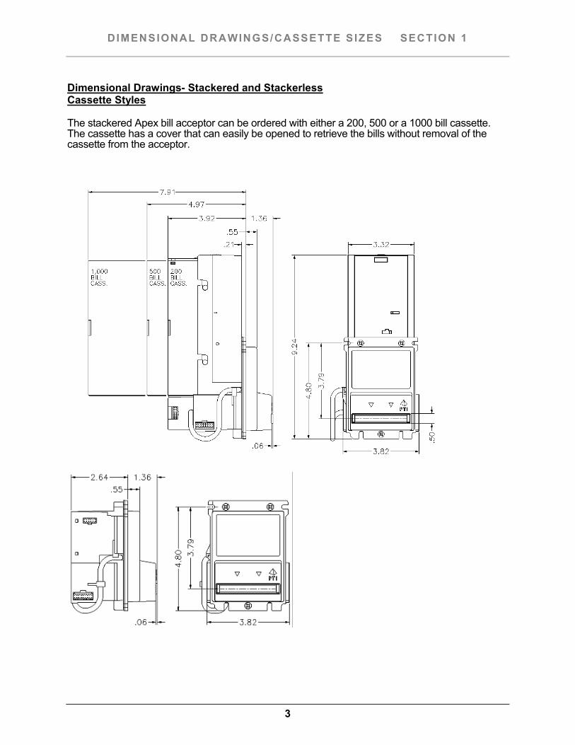
Dimensional Drawings- Stackered and Stackerless Cassette Styles The stackered Apex bill acceptor can be ordered with either a 200, 500 or a 1000 bill cassette. The cassette has a cover that can easily be opened to retrieve the bills without removal of the cassette from the acceptor.
4
OPTIONAL ACCESSORIES SECTION 1
The following is a list of optional accessories available from Pyramid Technologies, Inc. Description Part Number Acceptor I/O Harness, Generic P/N 05AA0002 This is an 18-pin harness to interface to the Apex bill acceptor I/O. All 18 wires are present. The wires are 36” long. HSV-300™ Compatible I/O Harness P/N 05AA0007 This harness plugs into our 18-pin I/O connector on the Apex bill acceptor and allows the user to connect the acceptor directly to a harness originally intended for an HSV-300 acceptor. This harness is a seven (7) pin connector and is 6” long Flash Download (Palm) Interface Harness P/N 05AA0011 This harness is used to interface a Palm to the Apex bill acceptor. This harness is used for acceptor diagnostics and flash software downloading. Please visit http://www.pyramidacceptors.com and go to the “Download” section to download the Palm program. For complete Palm documentation, see the “Support “ section of the web site. These files are also available upon request. Adapter Bracket Kit P/N 98AB0010 This kit is used to mount the Apex bill acceptor to a wood door. This kit comes with all necessary mounting hardware. RS-232 Communication Harness P/N 05AA0009 This harness is needed for true RS-232 communication. The harness comes with a DB9 connector on 36” of cable, as well as a hard drive connector on 36” of cable to obtain 12 VDC power for the bill acceptor from the PC. Order Document “RS232” for more details (or visit our web site). The “Download” section of our web site has a demo program which you can download to try out the PC interface. MDB Communication Harness P/N 05AA0010 APEX MDB Communication Board P/N 04AA0007 Both the harness and board are needed for MDB communication. The harness comes with an MDB style connector.
5
L IMITED WARRANTY SECTION 1
Limited Warranty Apex bill acceptors are warranted for a period of one (1) year from date of original invoice. This warranty extends to the original purchaser of the warranted product and each transferee owner of the product, during the term of the warranty. During the warranty period, manufacturer will repair or replace (at manufacture’s option) any parts, up to and including the complete acceptor, which fail to function properly because of defects in material or workmanship. This warranty covers bill acceptors only, which are designed to accept genuine currency. Manufacturer is not responsible for any consequential damage or performance degradation that results from counterfeit currency or foreign objects inserted into the bill acceptor. The product to be repaired under warranty must be delivered, inbound freight prepaid to an authorized service center. Upon request, the owner must show proof of purchase when submitting equipment for service during the warranty period. Repair or installation at the owner’s location is not included in warranty. During the warranty period, manufacturer will pay all outbound ground freight charges to the owner’s location. Special handling or shipping charges must be assumed by the owner. Manufacturer will not be liable for any consequential damages as a result of defects in material or workmanship. Any written or applied warranty of this product is strictly limited to the refund of the cost of goods purchased.Damage due to negligence, accidents, electrical overload, misuse, abuse, vandalism, or an act of God, is not covered by this warranty. Any alteration of the product after manufacture voids the warranty in its entirety. Shipping Damage When a product is returned to the owner after service, only consignee (the person or company receiving the bill acceptor) can file a claim against the carrier for concealed damages. Therefore, unpack immediately. Notify the delivery carrier of damages and request immediate inspection. Send a letter of intent to file claim to the carrier within 72 hours from the time of receipt. Send a copy of this letter to the shipper. Service For service information, please contact Pyramid Technologies, Inc. for a Service Center near you. For any items returned under warranty or for repair, complete written information including the serial and model number as well as a description of the malfunction or defects must be submitted to the Service Center when requesting a Return Material Authorization number (RMA number). Owner accepts full responsibility for any return without prior authorization. The RMA number must be displayed on the exterior of the returned product carton(s).
6
INSTALLATION/MOUNTING SECTION 2
Unpacking the Bill Acceptor Immediately inspect the bill acceptor for damage when unpacking it. If the acceptor is damaged, place it back in its original carton along with the packing materials. Notify the carrier of damages and request an immediate inspection of the package. Send a letter of intent to file a claim to the carrier within 72 hours from time of delivery. Please also send a copy of this letter to the shipper. Only the person or company receiving the bill acceptor can file a claim against the carrier for concealed damages. Installation/Mounting The Apex bill acceptor has been designed to easily mount onto existing studs in OEM equipment. If you are mounting the acceptor to a wood panel or door, you may require our optional Adapter Bracket (P/N 98AB0010). To install the acceptor: Disconnect all power to the machine.
Connect the interface cable from the machine to the acceptor.
On 120 VAC units, connect the 9-pin power plug to the machine. Install the green ring terminal ground wire to a stud that is part of the grounded frame.
Secure the harnesses in place using the provided tie wraps.
7
CONFIGURATION/CONFIGURATION CARD SECTION 2
The Apex bill acceptor has no DIP switches. It can be factory programmed to exactly fit your needs, or you can configure it using one of two methods. The first method is using the Configuration Card. This simple card allows you to program all features of the bill acceptor. The second method is using a Palm or in conjunction with our Flash Interface Cable (P/N 05AA0011). Using this method, you can quickly configure the bill acceptor. Please note that power must be applied to the bill acceptor to use either configuration method.
Configuration using a Palm
This method allows you to change the configuration of the Apex acceptor easily. Please order Document “Apex Palm Tools” for more details. See the section on Flash Programming for more details.
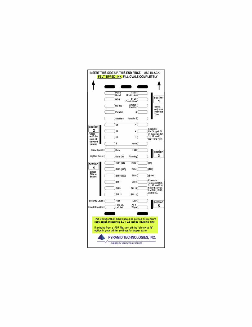
Configuration using the Configuration Card
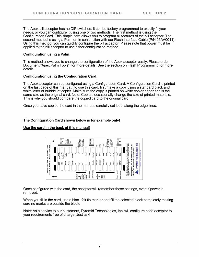
The Apex acceptor can be configured using a Configuration Card. A Configuration Card is printed on the last page of this manual. To use this card, first make a copy using a standard black and white laser or bubble jet copier. Make sure the copy is printed on white copier paper and is the same size as the original card. Note: Copiers occasionally change the size of printed materials. This is why you should compare the copied card to the original card.
Once you have copied the card in the manual, carefully cut it out along the edge lines.
The Configuration Card shown below is for example only!
Use the card in the back of this manual!
Once configured with the card, the acceptor will remember these settings, even if power is removed.
When you fill in the card, use a black felt tip marker and fill the selected block completely making sure no marks are outside the block.
Note: As a service to our customers, Pyramid Technologies, Inc. will configure each acceptor to your requirements free of charge. Just ask!
8
CONFIGURATION/CONFIGURATION CARD SECTION 2
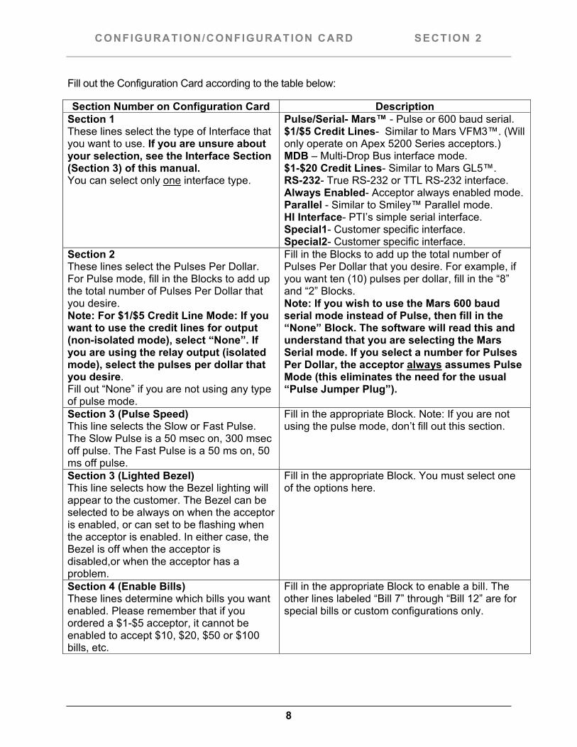
Fill out the Configuration Card according to the table below:
Section Number on Configuration Card Description Section 1 These lines select the type of Interface that you want to use. If you are unsure about your selection, see the Interface Section (Section 3) of this manual. You can select only one interface type.
Pulse/Serial- Mars™ - Pulse or 600 baud serial. $1/$5 Credit Lines- Similar to Mars VFM3™. (Will only operate on Apex 5200 Series acceptors.) MDB – Multi-Drop Bus interface mode. $1-$20 Credit Lines- Similar to Mars GL5™. RS-232- True RS-232 or TTL RS-232 interface. Always Enabled- Acceptor always enabled mode. Parallel - Similar to Smiley™ Parallel mode. HI Interface- PTI’s simple serial interface. Special1- Customer specific interface. Special2- Customer specific interface.
Section 2 These lines select the Pulses Per Dollar. For Pulse mode, fill in the Blocks to add up the total number of Pulses Per Dollar that you desire. Note: For $1/$5 Credit Line Mode: If you want to use the credit lines for output (non-isolated mode), select “None”. If you are using the relay output (isolated mode), select the pulses per dollar that you desire. Fill out “None” if you are not using any type of pulse mode.
Fill in the Blocks to add up the total number of Pulses Per Dollar that you desire. For example, if you want ten (10) pulses per dollar, fill in the “8” and “2” Blocks. Note: If you wish to use the Mars 600 baud serial mode instead of Pulse, then fill in the “None” Block. The software will read this and understand that you are selecting the Mars Serial mode. If you select a number for Pulses Per Dollar, the acceptor always assumes Pulse Mode (this eliminates the need for the usual “Pulse Jumper Plug”).
Section 3 (Pulse Speed) This line selects the Slow or Fast Pulse. The Slow Pulse is a 50 msec on, 300 msec off pulse. The Fast Pulse is a 50 ms on, 50 ms off pulse.
Fill in the appropriate Block. Note: If you are not using the pulse mode, don’t fill out this section.
Section 3 (Lighted Bezel) This line selects how the Bezel lighting will appear to the customer. The Bezel can be selected to be always on when the acceptor is enabled, or can set to be flashing when the acceptor is enabled. In either case, the Bezel is off when the acceptor is disabled,or when the acceptor has a problem.
Fill in the appropriate Block. You must select one of the options here.
Section 4 (Enable Bills) These lines determine which bills you want enabled. Please remember that if you ordered a $1-$5 acceptor, it cannot be enabled to accept $10, $20, $50 or $100 bills, etc.
Fill in the appropriate Block to enable a bill. The other lines labeled “Bill 7” through “Bill 12” are for special bills or custom configurations only.
9
CONFIGURATION/CONFIGURATION CARD SECTION 2
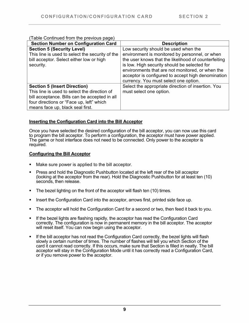
(Table Continued from the previous page) Section Number on Configuration Card Description
Section 5 (Security Level) This line is used to select the security of the bill acceptor. Select either low or high security.
Low security should be used when the environment is monitored by personnel, or when the user knows that the likelihood of counterfeiting is low. High security should be selected for environments that are not monitored, or when the acceptor is configured to accept high denomination currency. You must select one option.
Section 5 (Insert Direction) This line is used to select the direction of bill acceptance. Bills can be accepted in all four directions or “Face up, left” which means face up, black seal first.
Select the appropriate direction of insertion. You must select one option.
Inserting the Configuration Card into the Bill Acceptor
Once you have selected the desired configuration of the bill acceptor, you can now use this card to program the bill acceptor. To perform a configuration, the acceptor must have power applied. The game or host interface does not need to be connected. Only power to the acceptor is required.
Configuring the Bill Acceptor
Make sure power is applied to the bill acceptor. Press and hold the Diagnostic Pushbutton located at the left rear of the bill acceptor
(looking at the acceptor from the rear). Hold the Diagnostic Pushbutton for at least ten (10) seconds, then release.
The bezel lighting on the front of the acceptor will flash ten (10) times.
Insert the Configuration Card into the acceptor, arrows first, printed side face up.
The acceptor will hold the Configuration Card for a second or two, then feed it back to you.
If the bezel lights are flashing rapidly, the acceptor has read the Configuration Card correctly. The configuration is now in permanent memory in the bill acceptor. The acceptor will reset itself. You can now begin using the acceptor.
If the bill acceptor has not read the Configuration Card correctly, the bezel lights will flash slowly a certain number of times. The number of flashes will tell you which Section of the card it cannot read correctly. If this occurs, make sure that Section is filled in neatly. The bill acceptor will stay in the Configuration Mode until it has correctly read a Configuration Card, or if you remove power to the acceptor.

10
FLASH PROGRAMMING SECTION 2
Downloading new software to the Apex bill acceptor is accomplished using a Palm™. If you wish to change the software inside the acceptor, you must have an approved version of these devices. Request document “Apex_Palm_Tools” for more details, or visit our web site.
Flash Programming Primer
Instead of using an EPROM to hold the bill acceptor software, Pyramid Technologies, Inc. chose to use a Flash Device installed on the Apex bill acceptor’s Microprocessor Board. Using this device, there is no need to open the acceptor to change software. To change the acceptor’s software, you will plug a Palm into the six (6) pin connector located next to the Diagnostic Pushbutton (left rear of the acceptor as seen from the back). You also need to purchase the required Flash Interface Harness, P/N 05AA0011. After loading the required software onto the Palm, you can download new software to any bill acceptor at any location. The only requirement is that the acceptor has power applied. This method has the added benefit of allowing the Palm to be able to perform advanced diagnostics on the bill acceptor. This makes for an excellent troubleshooting device.
Our web site (www.pyramidacceptors.com) has the latest available software located in our “Download” Section, and documentation is available upon request, or from the “Support” section of our web site.
Palms are available from Pyramid Technologies, Inc. or you may purchase an approved device yourself.
11
TESTING SECTION 2
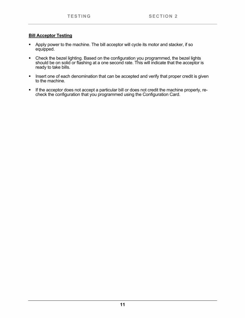
Bill Acceptor Testing
Apply power to the machine. The bill acceptor will cycle its motor and stacker, if so equipped.
Check the bezel lighting. Based on the configuration you programmed, the bezel lights should be on solid or flashing at a one second rate. This will indicate that the acceptor is ready to take bills.
Insert one of each denomination that can be accepted and verify that proper credit is given to the machine.
If the acceptor does not accept a particular bill or does not credit the machine properly, re-check the configuration that you programmed using the Configuration Card.
12
TROUBLESHOOTING/ON-BOARD DIAGNOSTICS SECTION 2
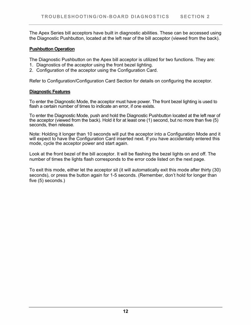
The Apex Series bill acceptors have built in diagnostic abilities. These can be accessed using the Diagnostic Pushbutton, located at the left rear of the bill acceptor (viewed from the back). Pushbutton Operation The Diagnostic Pushbutton on the Apex bill acceptor is utilized for two functions. They are: 1. Diagnostics of the acceptor using the front bezel lighting. 2. Configuration of the acceptor using the Configuration Card. Refer to Configuration/Configuration Card Section for details on configuring the acceptor. Diagnostic Features To enter the Diagnostic Mode, the acceptor must have power. The front bezel lighting is used to flash a certain number of times to indicate an error, if one exists.
To enter the Diagnostic Mode, push and hold the Diagnostic Pushbutton located at the left rear of the acceptor (viewed from the back). Hold it for at least one (1) second, but no more than five (5) seconds, then release.
Note: Holding it longer than 10 seconds will put the acceptor into a Configuration Mode and it will expect to have the Configuration Card inserted next. If you have accidentally entered this mode, cycle the acceptor power and start again. Look at the front bezel of the bill acceptor. It will be flashing the bezel lights on and off. The number of times the lights flash corresponds to the error code listed on the next page. To exit this mode, either let the acceptor sit (it will automatically exit this mode after thirty (30) seconds), or press the button again for 1-5 seconds. (Remember, don’t hold for longer than five (5) seconds.)
13
TROUBLESHOOTING/ON-BOARD DIAGNOSTICS SECTION 2
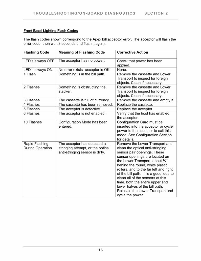
Front Bezel Lighting Flash Codes The flash codes shown correspond to the Apex bill acceptor error. The acceptor will flash the error code, then wait 3 seconds and flash it again. Flashing Code Meaning of Flashing Code Corrective Action
LED’s always OFF The acceptor has no power. Check that power has been
applied. LED’s always ON No error exists- acceptor is OK. None. 1 Flash Something is in the bill path. Remove the cassette and Lower
Transport to inspect for foreign objects. Clean if necessary.
2 Flashes Something is obstructing the stacker.
Remove the cassette and Lower Transport to inspect for foreign objects. Clean if necessary.
3 Flashes The cassette is full of currency. Remove the cassette and empty it. 4 Flashes The cassette has been removed. Replace the cassette. 5 Flashes The acceptor is defective. Replace the acceptor. 6 Flashes The acceptor is not enabled. Verify that the host has enabled
the acceptor. 10 Flashes Configuration Mode has been
entered. Configuration Card must be inserted into the acceptor or cycle power to the acceptor to exit this mode. See Configuration Section for details.
Rapid Flashing During Operation
The acceptor has detected a stringing attempt, or the optical anti-stringing sensor is dirty.
Remove the Lower Transport and clean the optical anti-stringing sensor pair openings. These sensor openings are located on the Lower Transport, about ½ “ behind the round, white plastic rollers, and to the far left and right of the bill path. It is a good idea to clean all of the sensors at this time, both the entire upper and lower halves of the bill path. Reinstall the Lower Transport and cycle the power.
14
MAINTENANCE SECTION 2
Maintenance
The Apex Series bill acceptor is relatively maintenance free. An occasional cleaning is all that is needed to keep the acceptor in top operation. To clean the acceptor:
Remove power from the machine. If equipped with a stacker, unlatch the cassette by pushing in the top latch and lifting the
cassette up and out.
Unplug the I/O connector and/or power connector from the right side of the acceptor. Note: You cannot remove the Lower Transport without first removing the I/O connector!
Remove the Lower Transport by pushing in the latch located on the bottom of the acceptor at the rear. Gently pull the Lower Transport out of the assembly.
Clean the bill path using a soft cloth or towel. Do not use any cleaners other than a 50/50 mixture of water and isopropyl alcohol.]
NOTE: Pay particular attention to the gray oval pieces of plastic in the lower and upper transport area. They must be cleaned well for proper operation.
Do not use any oils or silicon spray on the acceptor!
15
INTERFACE/CONNECTOR PINOUTS SECTION 3
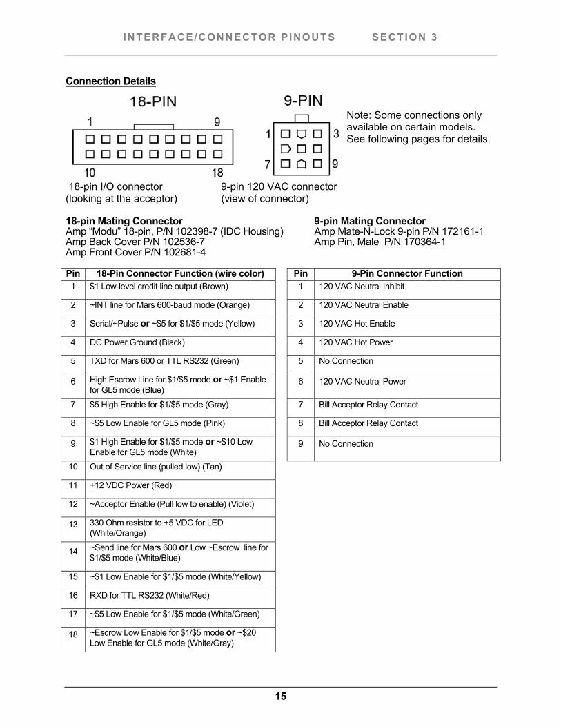
Connection Details
Note: Some connections only available on certain models. See following pages for details.
18-pin I/O connector 9-pin 120 VAC connector (looking at the acceptor) (view of connector) 18-pin Mating Connector 9-pin Mating Connector Amp “Modu” 18-pin, P/N 102398-7 (IDC Housing) Amp Mate-N-Lock 9-pin P/N 172161-1 Amp Back Cover P/N 102536-7 Amp Pin, Male P/N 170364-1 Amp Front Cover P/N 102681-4
Pin 18-Pin Connector Function (wire color) Pin 9-Pin Connector Function1 $1 Low-level credit line output (Brown) 1 120 VAC Neutral Inhibit
2 ~INT line for Mars 600-baud mode (Orange) 2 120 VAC Neutral Enable
3 Serial/~Pulse or ~$5 for $1/$5 mode (Yellow) 3 120 VAC Hot Enable
4 DC Power Ground (Black) 4 120 VAC Hot Power
5 TXD for Mars 600 or TTL RS232 (Green) 5 No Connection
6 High Escrow Line for $1/$5 mode or ~$1 Enable for GL5 mode (Blue)
6 120 VAC Neutral Power
7 $5 High Enable for $1/$5 mode (Gray) 7 Bill Acceptor Relay Contact
8 ~$5 Low Enable for GL5 mode (Pink) 8 Bill Acceptor Relay Contact
9 $1 High Enable for $1/$5 mode or ~$10 Low Enable for GL5 mode (White)
9 No Connection
10 Out of Service line (pulled low) (Tan)
11 +12 VDC Power (Red)
12 ~Acceptor Enable (Pull low to enable) (Violet)
13 330 Ohm resistor to +5 VDC for LED (White/Orange)
14 ~Send line for Mars 600 or Low ~Escrow line for $1/$5 mode (White/Blue)
15 ~$1 Low Enable for $1/$5 mode (White/Yellow)
16 RXD for TTL RS232 (White/Red)
17 ~$5 Low Enable for $1/$5 mode (White/Green)
18 ~Escrow Low Enable for $1/$5 mode or ~$20 Low Enable for GL5 mode (White/Gray)
16
INTERFACE/CONNECTOR PINOUTS SECTION 3
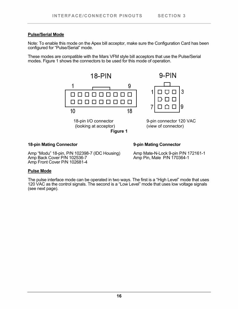
Pulse/Serial Mode
Note: To enable this mode on the Apex bill acceptor, make sure the Configuration Card has been configured for “Pulse/Serial” mode.
These modes are compatible with the Mars VFM style bill acceptors that use the Pulse/Serial modes. Figure 1 shows the connectors to be used for this mode of operation.
18-pin I/O connector 9-pin connector 120 VAC
(looking at acceptor) (view of connector) Figure 1
18-pin Mating Connector 9-pin Mating Connector
Amp “Modu” 18-pin, P/N 102398-7 (IDC Housing) Amp Mate-N-Lock 9-pin P/N 172161-1 Amp Back Cover P/N 102536-7 Amp Pin, Male P/N 170364-1 Amp Front Cover P/N 102681-4
Pulse Mode
The pulse interface mode can be operated in two ways. The first is a “High Level” mode that uses 120 VAC as the control signals. The second is a “Low Level” mode that uses low voltage signals (see next page).
17
INTERFACE/CONNECTOR PINOUTS SECTION 3
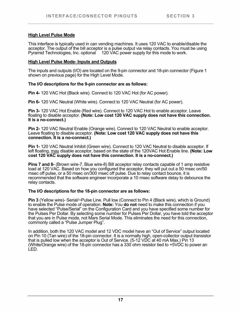
High Level Pulse Mode
This interface is typically used in can vending machines. It uses 120 VAC to enable/disable the acceptor. The output of the bill acceptor is a pulse output via relay contacts. You must be using Pyramid Technologies, Inc. optional 120 VAC power supply for this mode to work.
High Level Pulse Mode- Inputs and Outputs
The inputs and outputs (I/O) are located on the 9-pin connector and 18-pin connector (Figure 1 shown on previous page) for the High Level Mode.
The I/O descriptions for the 9-pin connector are as follows:
Pin 4- 120 VAC Hot (Black wire). Connect to 120 VAC Hot (for AC power).
Pin 6- 120 VAC Neutral (White wire). Connect to 120 VAC Neutral (for AC power).
Pin 3- 120 VAC Hot Enable (Red wire). Connect to 120 VAC Hot to enable acceptor. Leave floating to disable acceptor. (Note: Low cost 120 VAC supply does not have this connection. It is a no-connect.)
Pin 2- 120 VAC Neutral Enable (Orange wire). Connect to 120 VAC Neutral to enable acceptor. Leave floating to disable acceptor. (Note: Low cost 120 VAC supply does not have this connection. It is a no-connect.)
Pin 1- 120 VAC Neutral Inhibit (Green wire). Connect to 120 VAC Neutral to disable acceptor. If left floating, may disable acceptor, based on the state of the 120VAC Hot Enable line. (Note: Low cost 120 VAC supply does not have this connection. It is a no-connect.)
Pins 7 and 8- (Brown wire-7, Blue wire-8) Bill acceptor relay contacts capable of 1 amp resistive load at 120 VAC. Based on how you configured the acceptor, they will put out a 50 msec on/50 msec off pulse, or a 50 msec on/300 msec off pulse. Due to relay contact bounce, it is recommended that the software engineer incorporate a 10 msec software delay to debounce the relay contacts.
The I/O descriptions for the 18-pin connector are as follows:
Pin 3 (Yellow wire)- Serial/~Pulse Line. Pull low (Connect to Pin 4 (Black wire), which is Ground) to enable the Pulse mode of operation. Note: You do not need to make this connection if you have selected “Pulse/Serial” on the Configuration Card and you have specified some number for the Pulses Per Dollar. By selecting some number for Pulses Per Dollar, you have told the acceptor that you are in Pulse mode, not Mars Serial Mode. This eliminates the need for this connection, commonly called a “Pulse Jumper Plug”.
In addition, both the 120 VAC model and 12 VDC model have an “Out of Service” output located on Pin 10 (Tan wire) of the 18-pin connector. It is a normally high, open-collector output transistor that is pulled low when the acceptor is Out of Service. (5-12 VDC at 40 mA Max.) Pin 13 (White/Orange wire) of the 18-pin connector has a 330 ohm resistor tied to +5VDC to power an LED.
18
INTERFACE/CONNECTOR PINOUTS SECTION 3
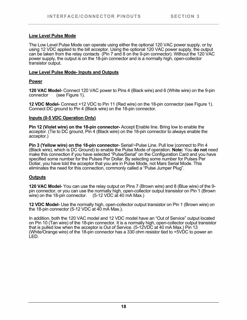
Low Level Pulse Mode
The Low Level Pulse Mode can operate using either the optional 120 VAC power supply, or by using 12 VDC applied to the bill acceptor. Using the optional 120 VAC power supply, the output can be taken from the relay contacts (Pin 7 and 8 on the 9-pin connector). Without the 120 VAC power supply, the output is on the 18-pin connector and is a normally high, open-collector transistor output.
Low Level Pulse Mode- Inputs and Outputs
Power
120 VAC Model- Connect 120 VAC power to Pins 4 (Black wire) and 6 (White wire) on the 9-pin connector (see Figure 1).
12 VDC Model- Connect +12 VDC to Pin 11 (Red wire) on the 18-pin connector (see Figure 1). Connect DC ground to Pin 4 (Black wire) on the 18-pin connector.
Inputs (0-5 VDC Operation Only)
Pin 12 (Violet wire) on the 18-pin connector- Accept Enable line. Bring low to enable the acceptor. (Tie to DC ground, Pin 4 (Black wire) on the 18-pin connector to always enable the acceptor.)
Pin 3 (Yellow wire) on the 18-pin connector- Serial/~Pulse Line. Pull low (connect to Pin 4 (Black wire), which is DC Ground) to enable the Pulse Mode of operation. Note: You do not need make this connection if you have selected “Pulse/Serial” on the Configuration Card and you have specified some number for the Pulses Per Dollar. By selecting some number for Pulses Per Dollar, you have told the acceptor that you are in Pulse Mode, not Mars Serial Mode. This eliminates the need for this connection, commonly called a “Pulse Jumper Plug”.
Outputs
120 VAC Model- You can use the relay output on Pins 7 (Brown wire) and 8 (Blue wire) of the 9-pin connector, or you can use the normally high, open-collector output transistor on Pin 1 (Brown wire) on the 18-pin connector. (5-12 VDC at 40 mA Max.)
12 VDC Model- Use the normally high, open-collector output transistor on Pin 1 (Brown wire) on the 18-pin connector (5-12 VDC at 40 mA Max.).
In addition, both the 120 VAC model and 12 VDC model have an “Out of Service” output located on Pin 10 (Tan wire) of the 18-pin connector. It is a normally high, open-collector output transistor that is pulled low when the acceptor is Out of Service. (5-12VDC at 40 mA Max.) Pin 13 (White/Orange wire) of the 18-pin connector has a 330 ohm resistor tied to +5VDC to power an LED.
19
INTERFACE/CONNECTOR PINOUTS SECTION 3
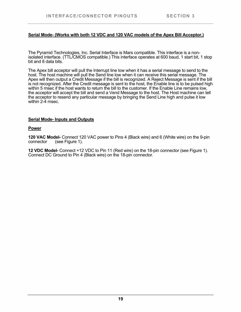
Serial Mode- (Works with both 12 VDC and 120 VAC models of the Apex Bill Acceptor.)
The Pyramid Technologies, Inc. Serial Interface is Mars compatible. This interface is a non-isolated interface. (TTL/CMOS compatible.) This interface operates at 600 baud, 1 start bit, 1 stop bit and 8 data bits.
The Apex bill acceptor will pull the Interrupt line low when it has a serial message to send to the host. The host machine will pull the Send line low when it can receive this serial message. The Apex will then output a Credit Message if the bill is recognized. A Reject Message is sent if the bill is not recognized. After the Credit message is sent to the host, the Enable line is to be pulsed high within 5 msec if the host wants to return the bill to the customer. If the Enable Line remains low, the acceptor will accept the bill and send a Vend Message to the host. The Host machine can tell the acceptor to resend any particular message by bringing the Send Line high and pulse it low within 2-4 msec.
Serial Mode- Inputs and Outputs
Power
120 VAC Model- Connect 120 VAC power to Pins 4 (Black wire) and 6 (White wire) on the 9-pin connector (see Figure 1).
12 VDC Model- Connect +12 VDC to Pin 11 (Red wire) on the 18-pin connector (see Figure 1). Connect DC Ground to Pin 4 (Black wire) on the 18-pin connector.
20
INTERFACE/CONNECTOR PINOUTS SECTION 3
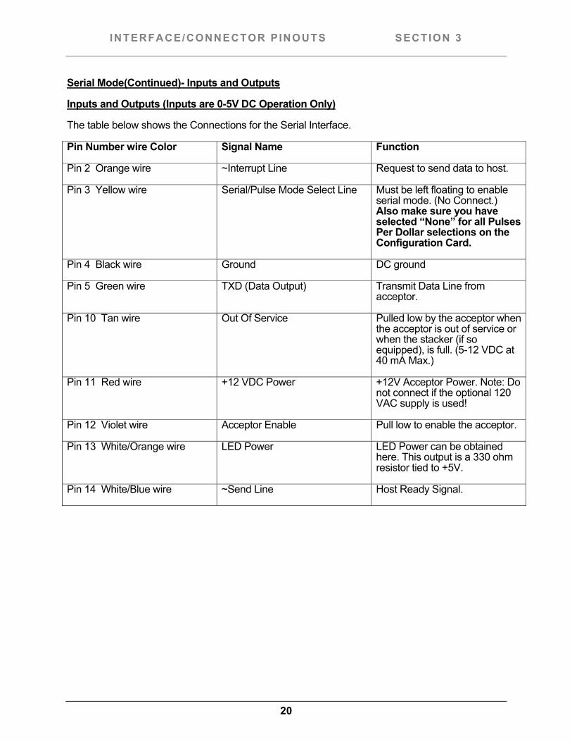
Serial Mode(Continued)- Inputs and Outputs
Inputs and Outputs (Inputs are 0-5V DC Operation Only)
The table below shows the Connections for the Serial Interface.
Pin Number wire Color Signal Name Function
Pin 2 Orange wire ~Interrupt Line Request to send data to host.
Pin 3 Yellow wire Serial/Pulse Mode Select Line Must be left floating to enable serial mode. (No Connect.) Also make sure you have selected “None” for all Pulses Per Dollar selections on the Configuration Card.
Pin 4 Black wire Ground DC ground
Pin 5 Green wire TXD (Data Output) Transmit Data Line from acceptor.
Pin 10 Tan wire Out Of Service Pulled low by the acceptor when the acceptor is out of service or when the stacker (if so equipped), is full. (5-12 VDC at 40 mA Max.)
Pin 11 Red wire +12 VDC Power +12V Acceptor Power. Note: Do not connect if the optional 120 VAC supply is used!
Pin 12 Violet wire Acceptor Enable Pull low to enable the acceptor.
Pin 13 White/Orange wire LED Power LED Power can be obtained here. This output is a 330 ohm resistor tied to +5V.
Pin 14 White/Blue wire ~Send Line Host Ready Signal.
21
INTERFACE/CONNECTOR PINOUTS SECTION 3
Serial Mode(Continued)
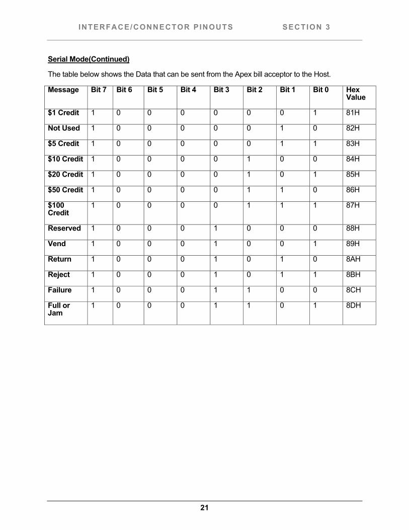
The table below shows the Data that can be sent from the Apex bill acceptor to the Host.
Message Bit 7 Bit 6 Bit 5 Bit 4 Bit 3 Bit 2 Bit 1 Bit 0 Hex Value
$1 Credit 1 0 0 0 0 0 0 1 81H
Not Used 1 0 0 0 0 0 1 0 82H
$5 Credit 1 0 0 0 0 0 1 1 83H
$10 Credit 1 0 0 0 0 1 0 0 84H
$20 Credit 1 0 0 0 0 1 0 1 85H
$50 Credit 1 0 0 0 0 1 1 0 86H
$100 Credit
1 0 0 0 0 1 1 1 87H
Reserved 1 0 0 0 1 0 0 0 88H
Vend 1 0 0 0 1 0 0 1 89H
Return 1 0 0 0 1 0 1 0 8AH
Reject 1 0 0 0 1 0 1 1 8BH
Failure 1 0 0 0 1 1 0 0 8CH
Full or Jam
1 0 0 0 1 1 0 1 8DH
22
INTERFACE/CONNECTOR PINOUTS SECTION 3
Low Level Credit Line Mode- $1 and $5 Model Only
This mode of operation is compatible with the Mars VFM3 low level interface that uses $1, $5 enable lines and escrow lines. The primary difference is that there is no $2 enable on the Apex bill acceptor, since it does not accept that bill.
Note: This interface is only available on the $1, $5 only 5200 Model of the Apex bill acceptor.
Note: To enable this mode on the acceptor, make sure the Configuration Card has been configured for “$1/$5 Credit Lines” mode.
In this mode, you use $1 and $5 high enable and low enable lines to enable a bill. The output of the bill acceptor is either the relay contacts (if an optional120 VAC power supply is used) or the $1 or $5 credit lines (see below for details).
Low Level Credit Line Mode- $1-$5 Model only - Inputs and Outputs
Power
120 VAC Model- Connect 120 VAC power to Pins 4 (Black wire) and 6 (White wire) on the 9-pin connector (see Figure 2).
12 VDC Model- Connect +12 VDC to Pin 11 (Red wire) on the 18-pin connector (see Figure 2) Connect DC Ground to Pin 4 (Black wire) on the 18-pin connector.
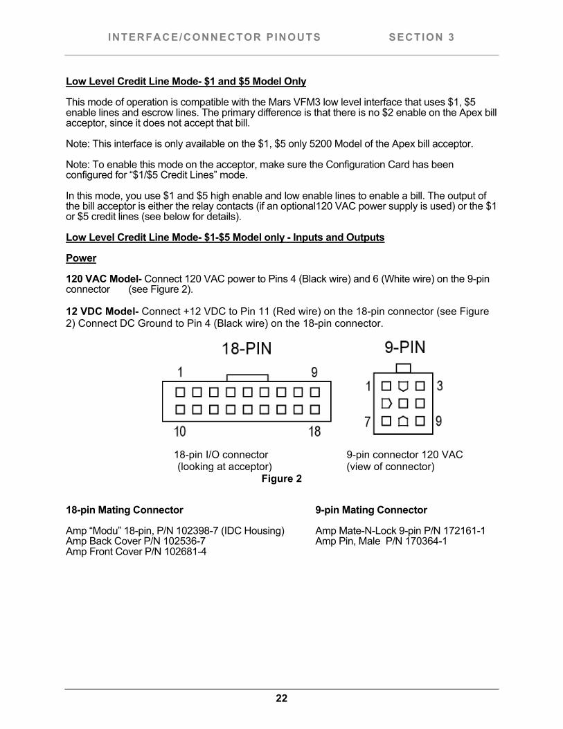
18-pin I/O connector 9-pin connector 120 VAC
(looking at acceptor) (view of connector) Figure 2
18-pin Mating Connector 9-pin Mating Connector
Amp “Modu” 18-pin, P/N 102398-7 (IDC Housing) Amp Mate-N-Lock 9-pin P/N 172161-1 Amp Back Cover P/N 102536-7 Amp Pin, Male P/N 170364-1 Amp Front Cover P/N 102681-4
23
INTERFACE/CONNECTOR PINOUTS SECTION 3
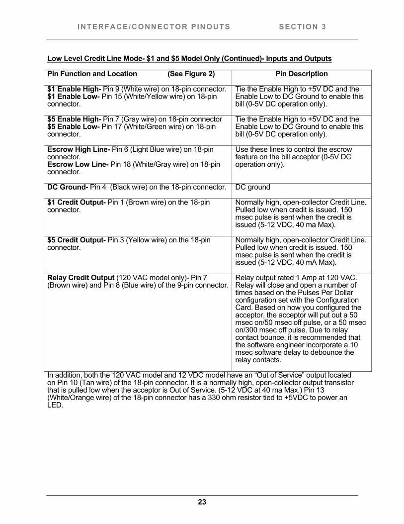
Low Level Credit Line Mode- $1 and $5 Model Only (Continued)- Inputs and Outputs
Pin Function and Location (See Figure 2) Pin Description
$1 Enable High- Pin 9 (White wire) on 18-pin connector. $1 Enable Low- Pin 15 (White/Yellow wire) on 18-pin connector.
Tie the Enable High to +5V DC and the Enable Low to DC Ground to enable this bill (0-5V DC operation only).
$5 Enable High- Pin 7 (Gray wire) on 18-pin connector $5 Enable Low- Pin 17 (White/Green wire) on 18-pin connector.
Tie the Enable High to +5V DC and the Enable Low to DC Ground to enable this bill (0-5V DC operation only).
Escrow High Line- Pin 6 (Light Blue wire) on 18-pin connector. Escrow Low Line- Pin 18 (White/Gray wire) on 18-pin connector.
Use these lines to control the escrow feature on the bill acceptor (0-5V DC operation only).
DC Ground- Pin 4 (Black wire) on the 18-pin connector. DC ground
$1 Credit Output- Pin 1 (Brown wire) on the 18-pin connector.
Normally high, open-collector Credit Line. Pulled low when credit is issued. 150 msec pulse is sent when the credit is issued (5-12 VDC, 40 ma Max).
$5 Credit Output- Pin 3 (Yellow wire) on the 18-pin connector.
Normally high, open-collector Credit Line. Pulled low when credit is issued. 150 msec pulse is sent when the credit is issued (5-12 VDC, 40 mA Max).
Relay Credit Output (120 VAC model only)- Pin 7 (Brown wire) and Pin 8 (Blue wire) of the 9-pin connector.
Relay output rated 1 Amp at 120 VAC. Relay will close and open a number of times based on the Pulses Per Dollar configuration set with the Configuration Card. Based on how you configured the acceptor, the acceptor will put out a 50 msec on/50 msec off pulse, or a 50 msec on/300 msec off pulse. Due to relay contact bounce, it is recommended that the software engineer incorporate a 10 msec software delay to debounce the relay contacts.
In addition, both the 120 VAC model and 12 VDC model have an “Out of Service” output located on Pin 10 (Tan wire) of the 18-pin connector. It is a normally high, open-collector output transistor that is pulled low when the acceptor is Out of Service. (5-12 VDC at 40 ma Max.) Pin 13 (White/Orange wire) of the 18-pin connector has a 330 ohm resistor tied to +5VDC to power an LED.
24
INTERFACE/CONNECTOR PINOUTS SECTION 3
Low Level Credit Line Mode- $1-$20 Model Only
This mode of operation is compatible with the Mars VFM3S™, VFM5S™, GL5™ or LE3000™ Low Level interface that uses $1-$20 enable lines. This interface should only be used on a Model 5400 Apex bill acceptor.
Note: To enable this mode on the acceptor, make sure the Configuration Card has been configured for “$1-$20 Credit Lines” mode.
In this mode, you use $1-$20 enable lines to enable a bill. The output of the bill acceptor is either the relay contacts (if an optional120 VAC power supply is used) or the Low Level Non-Isolated Credit Line (see the next page for details).
Low Level Credit Line Mode- $1-$20 Model Only- Inputs and Outputs
Power
120 VAC Model- Connect 120 VAC power to Pins 4 (Black wire) and 6 (White wire) on the 9-pin connector (see Figure 2).
12 VDC Model- Connect +12 VDC to Pin 11 (Red wire) on the 18-pin connector (See Figure 2) Connect DC Ground to Pin 4 (Black wire) on the 18-pin connector.
In addition, both the 120 VAC model and 12 VDC model have an “Out of Service” output located on Pin 10 (Tan wire) of the 18-pin connector. It is a normally high, open-collector output transistor that is pulled low when the acceptor is Out of Service. (5-12 VDC at 40 ma Max.) Pin 13 (White/Orange wire) of the 18-pin connector has a 330 ohm resistor tied to +5VDC to power an LED.
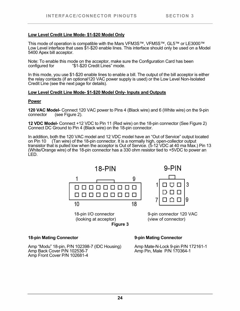
18-pin I/O connector 9-pin connector 120 VAC
(looking at acceptor) (view of connector) Figure 3
18-pin Mating Connector 9-pin Mating Connector
Amp “Modu” 18-pin, P/N 102398-7 (IDC Housing) Amp Mate-N-Lock 9-pin P/N 172161-1 Amp Back Cover P/N 102536-7 Amp Pin, Male P/N 170364-1 Amp Front Cover P/N 102681-4
25
INTERFACE/CONNECTOR PINOUTS SECTION 3
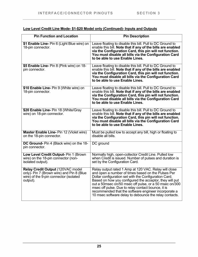
Low Level Credit Line Mode- $1-$20 Model only (Continued)- Inputs and Outputs
Pin Function and Location Pin Description
$1 Enable Line- Pin 6 (Light Blue wire) on 18-pin connector.
Leave floating to disable this bill. Pull to DC Ground to enable this bill. Note that if any of the bills are enabled via the Configuration Card, this pin will not function. You must disable all bills via the Configuration Card to be able to use Enable Lines.
$5 Enable Line- Pin 8 (Pink wire) on 18-pin connector.
Leave floating to disable this bill. Pull to DC Ground to enable this bill. Note that if any of the bills are enabled via the Configuration Card, this pin will not function. You must disable all bills via the Configuration Card to be able to use Enable Lines.
$10 Enable Line- Pin 9 (White wire) on 18-pin connector.
Leave floating to disable this bill. Pull to DC Ground to enable this bill. Note that if any of the bills are enabled via the Configuration Card, this pin will not function. You must disable all bills via the Configuration Card to be able to use Enable Lines.
$20 Enable Line- Pin 18 (White/Gray wire) on 18-pin connector.
Leave floating to disable this bill. Pull to DC Ground to enable this bill. Note that if any of the bills are enabled via the Configuration Card, this pin will not function. You must disable all bills via the Configuration Card to be able to use Enable Lines.
Master Enable Line- Pin 12 (Violet wire) on the 18-pin connector.
Must be pulled low to accept any bill, high or floating to disable all bills.
DC Ground- Pin 4 (Black wire) on the 18-pin connector.
DC ground
Low Level Credit Output- Pin 1 (Brown wire) on the 18-pin connector (non-isolated output).
Normally high, open-collector Credit Line. Pulled low when Credit is issued. Number of pulses and duration is set by the Configuration Card.
Relay Credit Output (120VAC model only)- Pin 7 (Brown wire) and Pin 8 (Blue wire) of the 9-pin connector (isolated output).
Relay output rated 1 Amp at 120 VAC. Relay will close and open a number of times based on the Pulses Per Dollar configuration set with the Configuration Card. Based on how you configured the acceptor, they will put out a 50msec on/50 msec off pulse, or a 50 msec on/300 msec off pulse. Due to relay contact bounce, it is recommended that the software engineer incorporate a 10 msec software delay to debounce the relay contacts.
26
INTERFACE/CONNECTOR PINOUTS SECTION 3
Always Enabled Mode of Operation
This mode of operation is the simplest to understand. In this mode, the acceptor is always enabled. It will accept all valid bills that are programmed to be accepted by the Configuration Card. Note: to enable this mode on the acceptor, make sure the Configuration Card has been configured for “Always Enabled” mode. The output of the bill acceptor is either the relay contacts (if a 120 VAC optional supply is used), or the Low Level Non-Isolated Credit Line (see below for details).
Always Enabled Mode- Outputs
Power
120 VAC Model- Connect 120 VAC power to Pins 4 (Black wire) and 6 (White wire) on the 9-pin connector (see Figure 4). 12 VDC Model- Connect +12 VDC to Pin 11 (Red wire) on the 18-pin connector (see Figure 4). Connect DC Ground to Pin 4 (Black wire) on the 18-pin connector.
In addition, both the 120 VAC model and 12 VDC model have an “Out of Service” output located on Pin 10 (Tan wire) of the 18-pin connector. It is a normally high, open-collector output transistor that is pulled low when the acceptor is Out of Service. (5-12 VDC at 40 ma Max.) Pin 13 (White/Orange wire) of the 18-pin connector has a 330 ohm resistor tied to +5VDC to power an LED.
Outputs
120 VAC Model- You can use the relay output on Pin 7 (Brown) and Pin 8 (Blue) of the 9-pin connector, or you can use the normally high, open-collector output transistor on Pin 1 (Brown wire) on the 18-pin connector. (5-12 VDC at 40 mA Max.)
12 VDC Model- Use the normally high, open-collector output transistor on Pin 1 (Brown wire) on the 18-pin connector (5-12 VDC at 40 mA max.) All outputs will send the number of pulses and pulse speed as set by the Configuration Card.
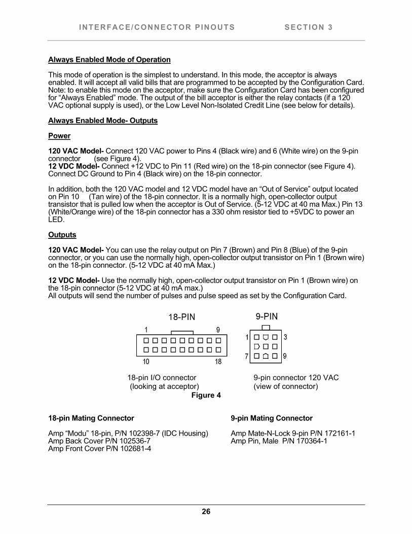
18-pin I/O connector 9-pin connector 120 VAC
(looking at acceptor) (view of connector) Figure 4
18-pin Mating Connector 9-pin Mating Connector
Amp “Modu” 18-pin, P/N 102398-7 (IDC Housing) Amp Mate-N-Lock 9-pin P/N 172161-1 Amp Back Cover P/N 102536-7 Amp Pin, Male P/N 170364-1 Amp Front Cover P/N 102681-4
27
INTERFACE/CONNECTOR PINOUTS SECTION 3
RS-232 Mode (True RS-232 and TTL RS-232)
Note: To enable this mode on the acceptor, make sure the Configuration Card has been configured for “RS-232” mode.
In this mode, the user has a choice of True RS-232 levels or TTL levels.
TTL (5 VDC) levels are available in both a 120 VAC version and a 12 VDC version of the Apex bill acceptor. Order our Acceptor I/O Harness, Generic (P/N 05AA0002). With this cable, you must manually connect the wires to your machine.
True RS-232 levels are available only in the 12 VDC Model of the Apex bill acceptor. In the 12 VDC version, the harness has a DB-9 connector and hard drive connector installed to ease customer installation. Order RS-232 Communication Harness (P/N 05AA0009) to have this ability.
This RS-232 mode uses a three wire interface. This interface uses a Transmit Line (TXD), a Receive Line (RXD) and DC ground (Gnd).
This RS-232 Interface is compatible with the interface used on Mars™ GL5™ style acceptors. It is a polled interface where the host machine is the Master and the bill acceptor is the Slave.
For RS-232 communication protocol details, see the “support” section of our website.
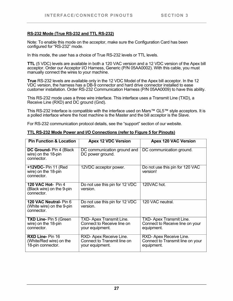
TTL RS-232 Mode Power and I/O Connections (refer to Figure 5 for Pinouts)
Pin Function & Location Apex 12 VDC Version Apex 120 VAC Version
DC Ground- Pin 4 (Black wire) on the 18-pin connector.
DC communication ground and DC power ground.
DC communication ground.
+12VDC- Pin 11 (Red wire) on the 18-pin connector.
12VDC acceptor power. Do not use this pin for 120 VAC version!
120 VAC Hot- Pin 4 (Black wire) on the 9-pin connector.
Do not use this pin for 12 VDC version.
120VAC hot.
120 VAC Neutral- Pin 6 (White wire) on the 9-pin connector.
Do not use this pin for 12 VDC version.
120 VAC neutral.
TXD Line- Pin 5 (Green wire) on the 18-pin connector.
TXD- Apex Transmit Line. Connect to Receive line on your equipment.
TXD- Apex Transmit Line. Connect to Receive line on your equipment.
RXD Line- Pin 16 (White/Red wire) on the 18-pin connector.
RXD- Apex Receive Line. Connect to Transmit line on your equipment.
RXD- Apex Receive Line. Connect to Transmit line on your equipment.
28
INTERFACE/CONNECTOR PINOUTS SECTION 3
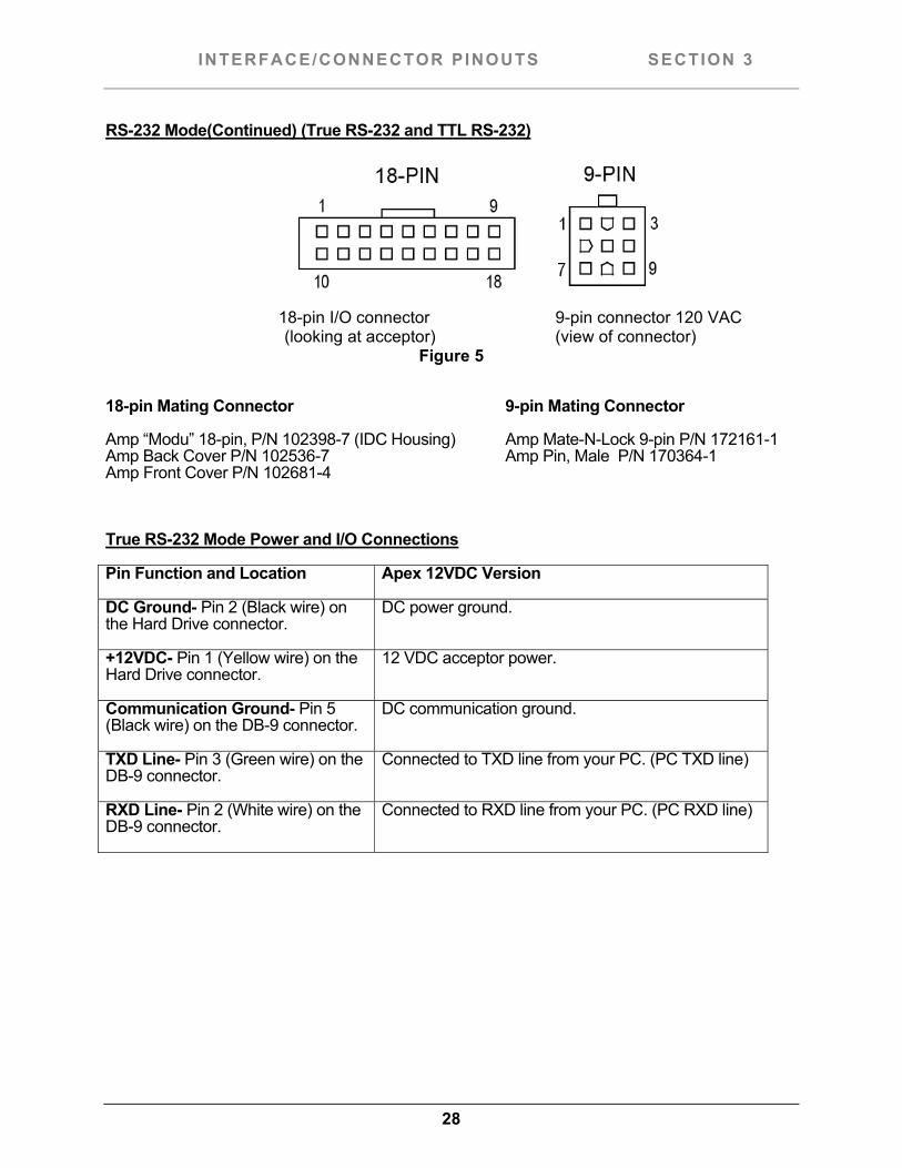
RS-232 Mode(Continued) (True RS-232 and TTL RS-232)
18-pin I/O connector 9-pin connector 120 VAC
(looking at acceptor) (view of connector) Figure 5
18-pin Mating Connector 9-pin Mating Connector
Amp “Modu” 18-pin, P/N 102398-7 (IDC Housing) Amp Mate-N-Lock 9-pin P/N 172161-1 Amp Back Cover P/N 102536-7 Amp Pin, Male P/N 170364-1 Amp Front Cover P/N 102681-4
True RS-232 Mode Power and I/O Connections
Pin Function and Location Apex 12VDC Version
DC Ground- Pin 2 (Black wire) on the Hard Drive connector.
DC power ground.
+12VDC- Pin 1 (Yellow wire) on the Hard Drive connector.
12 VDC acceptor power.
Communication Ground- Pin 5 (Black wire) on the DB-9 connector.
DC communication ground.
TXD Line- Pin 3 (Green wire) on the DB-9 connector.
Connected to TXD line from your PC. (PC TXD line)
RXD Line- Pin 2 (White wire) on the DB-9 connector.
Connected to RXD line from your PC. (PC RXD line)
29
INTERFACE/CONNECTOR PINOUTS SECTION 3
MDB Mode of Operation
Note: To enable this mode on the acceptor, make sure the Configuration Card has been configured for “MDB” mode.
MDB, or Multi-Drop Bus is a communication standard adopted by NAMA. In this configuration up to thirty-two (32) peripherals (or Slaves) can communicate to one Host (Master).
The Master initiates all communication to all devices on the bus.
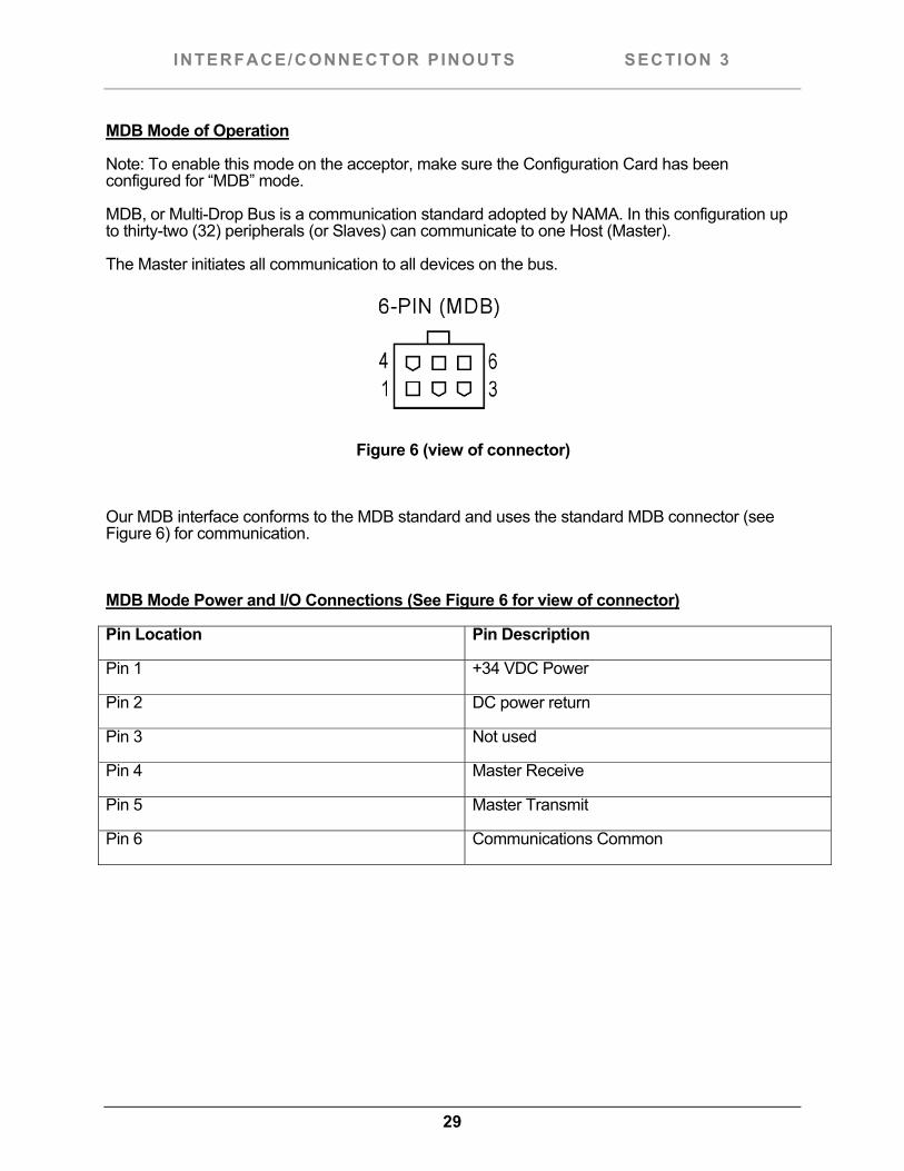
Figure 6 (view of connector)
Our MDB interface conforms to the MDB standard and uses the standard MDB connector (see Figure 6) for communication.
MDB Mode Power and I/O Connections (See Figure 6 for view of connector)
Pin Location Pin Description
Pin 1 +34 VDC Power
Pin 2 DC power return
Pin 3 Not used
Pin 4 Master Receive
Pin 5 Master Transmit
Pin 6 Communications Common
30
INTERFACE/CONNECTOR PINOUTS SECTION 3
Parallel Mode of Operation
Note: To enable this mode on the acceptor, make sure the Configuration Card has been configured for “Parallel” mode. The Parallel mode is compatible with the Innovative Technologies™ “Smiley™ bill acceptor.
In this mode, a single output is applied to one of four Vend lines to show which bill has been accepted. This allows you to have up to four denominations of bills to be accepted. Also provided in this interface is an Alarm line to indicate an abnormal condition. An Escrow line is also provided to allow more control over which bill is accepted by the Apex bill acceptor.
This mode can be used in our 12 VDC models as well as our 120 VAC models.
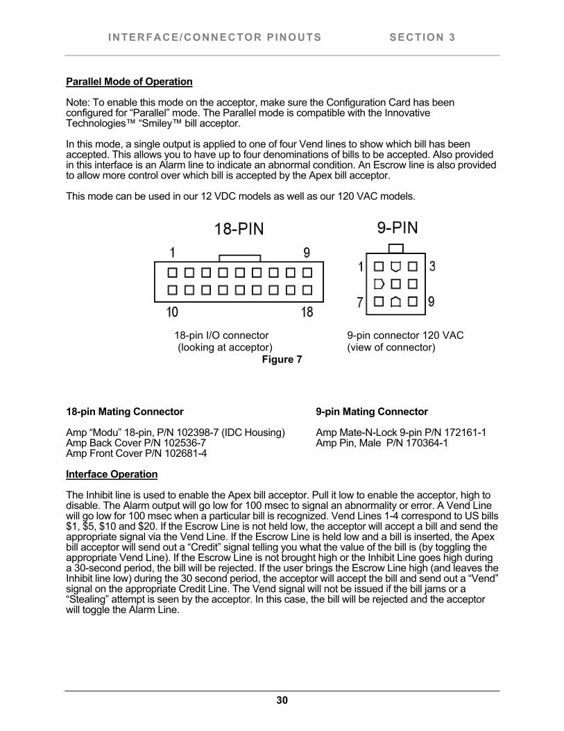
18-pin I/O connector 9-pin connector 120 VAC
(looking at acceptor) (view of connector) Figure 7
18-pin Mating Connector 9-pin Mating Connector
Amp “Modu” 18-pin, P/N 102398-7 (IDC Housing) Amp Mate-N-Lock 9-pin P/N 172161-1 Amp Back Cover P/N 102536-7 Amp Pin, Male P/N 170364-1 Amp Front Cover P/N 102681-4
Interface Operation
The Inhibit line is used to enable the Apex bill acceptor. Pull it low to enable the acceptor, high to disable. The Alarm output will go low for 100 msec to signal an abnormality or error. A Vend Line will go low for 100 msec when a particular bill is recognized. Vend Lines 1-4 correspond to US bills $1, $5, $10 and $20. If the Escrow Line is not held low, the acceptor will accept a bill and send the appropriate signal via the Vend Line. If the Escrow Line is held low and a bill is inserted, the Apex bill acceptor will send out a “Credit” signal telling you what the value of the bill is (by toggling the appropriate Vend Line). If the Escrow Line is not brought high or the Inhibit Line goes high during a 30-second period, the bill will be rejected. If the user brings the Escrow Line high (and leaves the Inhibit line low) during the 30 second period, the acceptor will accept the bill and send out a “Vend” signal on the appropriate Credit Line. The Vend signal will not be issued if the bill jams or a “Stealing” attempt is seen by the acceptor. In this case, the bill will be rejected and the acceptor will toggle the Alarm Line.
31
INTERFACE/CONNECTOR PINOUTS SECTION 3
Parallel Mode of Operation(Continued)
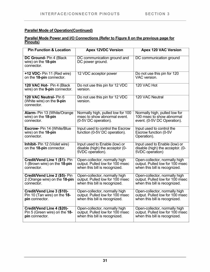
Parallel Mode Power and I/O Connections (Refer to Figure 8 on the previous page for Pinouts)
Pin Function & Location Apex 12VDC Version Apex 120 VAC Version
DC Ground- Pin 4 (Black wire) on the 18-pin connector.
DC communication ground and DC power ground.
DC communication ground
+12 VDC- Pin 11 (Red wire) on the 18-pin connector.
12 VDC acceptor power Do not use this pin for 120 VAC version.
120 VAC Hot- Pin 4 (Black wire) on the 9-pin connector.
Do not use this pin for 12 VDC version.
120 VAC Hot
120 VAC Neutral- Pin 6 (White wire) on the 9-pin connector.
Do not use this pin for 12 VDC version.
120 VAC Neutral
Alarm- Pin 13 (White/Orange wire) on the 18-pin connector.
Normally high, pulled low for 100 msec to show abnormal event. (0-5V DC operation).
Normally high, pulled low for 100 msec to show abnormal event. (0-5V DC Operation).
Escrow- Pin 14 (White/Blue wire) on the 18-pin connector.
Input used to control the Escrow function (0-5V DC operation).
Input used to control the Escrow function (0-5V Operation).
Inhibit- Pin 12 (Violet wire) on the 18-pin connector.
Input used to Enable (low) or disable (high) the acceptor (0-5VDC operation).
Input used to Enable (low) or disable (high) the acceptor. (0-5VDC operation)
Credit/Vend Line 1 ($1)- Pin 1 (Brown wire) on the 18-pin connector.
Open-collector, normally high output. Pulled low for 100 msec when this bill is recognized.
Open-collector, normally high output. Pulled low for 100 msec when this bill is recognized.
Credit/Vend Line 2 ($5)- Pin 2 (Orange wire) on the 18-pin connector.
Open-collector, normally high output. Pulled low for 100 msec when this bill is recognized.
Open-collector, normally high output. Pulled low for 100 msec when this bill is recognized.
Credit/Vend Line 3 ($10)- Pin 10 (Tan wire) on the 18-pin connector.
Open-collector, normally high output. Pulled low for 100 msec when this bill is recognized.
Open-collector, normally high output. Pulled low for 100 msec when this bill is recognized.
Credit/Vend Line 4 ($20)- Pin 5 (Green wire) on the 18-pin connector.
Open-collector, normally high output. Pulled low for 100 msec when this bill is recognized.
Open-collector, normally high output. Pulled low for 100 msec when this bill is recognized.
32
CONFIGURATION CARD SECTION 3
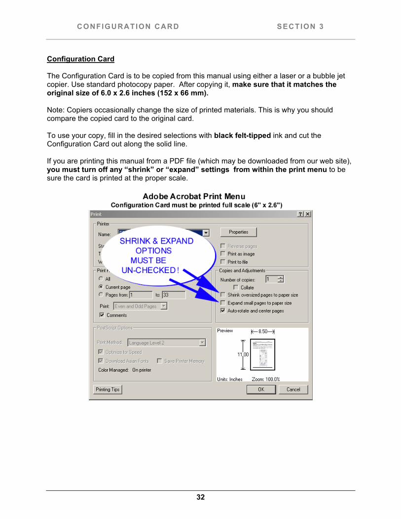
Configuration Card The Configuration Card is to be copied from this manual using either a laser or a bubble jet copier. Use standard photocopy paper. After copying it, make sure that it matches the original size of 6.0 x 2.6 inches (152 x 66 mm). Note: Copiers occasionally change the size of printed materials. This is why you should compare the copied card to the original card. To use your copy, fill in the desired selections with black felt-tipped ink and cut the Configuration Card out along the solid line. If you are printing this manual from a PDF file (which may be downloaded from our web site), you must turn off any “shrink” or “expand” settings from within the print menu to be sure the card is printed at the proper scale.