APEX LOCATOR - forumforumtec.net/wp-content/uploads/2016/10/A5-Paper... · This apex locator has...
18
APEX LOCATOR User Manual
Transcript of APEX LOCATOR - forumforumtec.net/wp-content/uploads/2016/10/A5-Paper... · This apex locator has...

APEX LOCATOR User Manual

- 1 -
Table of Contents
Introduction ………………………………………………..….... 2
1. Indications for use …….…………………………………….…. 3
2. Contraindications …………………………………………..….. 3
3. Warnings ……………………………………..…………..…….. 3
4. Precautions .……………………………...………………..…… 3
5. Adverse Reactions ……………………………………..……… 4
6. Step by step instructions …….……………………………..…. 4
6.1 Packaging Box Content …….……………………..…....... 4
6.2 Recharging the Battery ..…………………………..……… 4
6.3 Getting Started …………………………………..…..…..... 4
6.4 Cable connection test …….…………………………..…... 5
6.5 Apex Localization ………….…………………….…..……. 5
6.6 Audio Feedback …………………………………..…..…… 7
6.7 Virtual Apex ……………………………………………..…. 7
6.8 Demo mode ..…………………………………………….... 8
6.9 Automatic Shutdown ..……….…………………..……….. 9
7. Battery Charging …............................................................. 9
7.1. Battery replacement ..................................................... 10
8. Maintenance, cleaning and sterilization …..…………….…. 10
8.1 General ……………………………………………………. 10
8.2 Disinfection and sterilization procedure ……………….. 11
9. Troubleshooting ………………………………………………. 12
10. Warranty ……..………………………….……………………. 13
11. Disclaimer ………..……………………….…………………... 14
12. Certification …………….………………….….……………… 14
13. European Authorized Representative ……...………………. 14
14. Technical Specifications ……………………..………………. 15
15. Standard symbols …..……………………….….…………….. 15

- 2 -
FOR DENTAL USE ONLY
DIRECTIONS FOR USE
Introduction
You have made a good choice with – the most innovative apex locator on the market. This apex locator has been optimized inheriting proven technology and measurement precision of well known Bingo line of electronic apex locators and implementing unique full color 3D user interface.
Ergonomic user-friendly design of makes it a choice of preference in modern dental clinic.

- 3 -
1. Indications for use
is an electronic device used for apex localization and working length determination during root canal treatment. The device enables to obtain correct results in canals with different conditions (dry, wet, blood, etc.).
2. Contraindications
The is not recommended for use in patients that have a pacemaker or other implanted electrical devices.
3. Warnings
This product must only be used in hospital environments, clinics or dental offices by qualified dental personnel.
Use only the original charger.
4. Precautions
Do not use near devices emitting electromagnetic noise such as fluorescent lamps, film viewers, ultrasonic devices, etc. Cellular phones, remote controls or other
devices generating electromagnetic waves may cause abnormal operation of . Such devices should be turned off.
During device operation protect from occasional liquid spillage.
Do not use in the presence of flammable materials.
The device should be used with the manufacturer's original accessories only.
In order to prevent infectious agent transmission it is highly recommended to use a rubber dam system during the endodontic procedure.
To ensure that short circuits do not impair the measurements, be particularly careful with patients fitted with metal crowns or bridges (avoid any metallic contact with the file or the lip clip).
High concentrations of sodium hypochlorite may result in a lower accuracy of the measurements. For working length determination, we recommend to use sodium hypochlorite solution at maximum 3% concentration.
Make sure that the canal is wet enough to ensure reliability of the measurement.
Ensure that the file does not touch another instrument.
Avoid excessive liquids inside the tooth cavity to prevent overflow and incorrect measurements.
must be stored at normal temperature (< 60°C) and humidity conditions.
Teeth with open apices will give imprecise results.
An apex locator may not be able to measure in all conditions. In any case, it is recommended to take an X-Ray prior to use of the device and to compare the results obtained by both methods.
For your own safety, please use personal protection means (gloves, mask).
- 4 -
5. Adverse Reactions:
None.
6. Step-by-Step Instructions
6.1. Packaging Box Content
Check the content of the equipment before use:
- apex locator - 1pc. - Charger - 1pc. - Measurement cable - 1pc. - Lip clip - 5pcs. - File clip - 2pcs. - Touch probe - 1pc. - User Manual - 1pc.
6.2 Recharging the Battery
Before the first use or after prolonged storage should be recharged. Refer to the section 7 for battery recharging instructions.
6.3 Getting Started
Prior the first use, it is recommended to sterilize the Lip Clip, the Touch Probe and the File
Clip. Please refer to section 8 for further information regarding maintenance.
6.3.1. Disconnect the charger from the device, if connected.
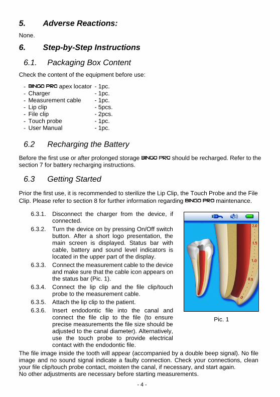
6.3.2. Turn the device on by pressing On/Off switch button. After a short logo presentation, the main screen is displayed. Status bar with cable, battery and sound level indicators is located in the upper part of the display.
6.3.3. Connect the measurement cable to the device and make sure that the cable icon appears on the status bar (Pic. 1).
6.3.4. Connect the lip clip and the file clip/touch probe to the measurement cable.
6.3.5. Attach the lip clip to the patient.
6.3.6. Insert endodontic file into the canal and connect the file clip to the file (to ensure precise measurements the file size should be adjusted to the canal diameter). Alternatively, use the touch probe to provide electrical contact with the endodontic file.
The file image inside the tooth will appear (accompanied by a double beep signal). No file image and no sound signal indicate a faulty connection. Check your connections, clean your file clip/touch probe contact, moisten the canal, if necessary, and start again. No other adjustments are necessary before starting measurements.
Pic. 1
Pic. 1

- 5 -
6.4 Cable connection test
Connection test feature is included in in order to check the cables: ● Connect the file clip contact to the lip clip. ● “Connection” symbol should appear on the status bar of the display, indicating
proper connection (Pic. 2). ● If the symbol do not appear, the measurement cable or the file clip should be replaced.
6.5 Apex localization
6.5.1 Coronal and Medial Zone
Slowly introduce the file into the canal. The progression of the file inside the canal shown inside the tooth image on the left part of the display (Pic. 3 to Pic. 5).
Pic. 2
Pic. 3 Pic. 4 Pic. 5

- 6 -
Along the pre-apical zone a zoomed view of file progression in the canal is shown on the enlarged root image on the right side of the display as well, and numerical value appears on the left side of the display under the tooth image.
provides audio feedback of file progression as a series of progressive rate beeps.
6.5.2 Apical Zone
The apical zone is divided into 11 segments graduated from 1.0 to 0 (Apex) as visual information of file progression.
When the apex is reached (read bar at the mark “0” and reading “APEX”), solid tone is
emitted.
Beginning of the Apical Zone
Middle of the Apical Zone
To determine the working length for shaping, it is recommended to subtract 0.5 mm from the apical length.
Pic. 6 Pic. 7 Pic. 8
Pic. 9 Pic. 10 Pic. 11
Apical position Reached

- 7 -
6.5.3 Over-instrumentation
A red “Blood drop” and warning sound indicate that the file has passed the Apex, Numerical values changing from +0.1 to +0.5 (Pic. 12 and Pic. 13) indicate relative depth of over-
instrumentation, then “OVER” reading appears. (Pic. 14).
6.6. Audio feedback
is equipped with a audio indicator which enables monitoring of the progression of the file within the canal in the apical zone.
This function, is activated in parallel with Apical Zoom display and enables monitoring of file advance in the apical zone, even without seeing the display.
The volume can be adjusted to one of four levels: mute, low, normal and high, by
successive pressings of the volume key.
6.7. Virtual Apex
Virtual apex enables to mark a predetermined position at the required distance from the apex. When Virtual Apex feature is enabled, the dentist gets clear visual and audio indication that the file tip has reached the selected position near the Apex.
To activate Virtual Apex or to modify Virtual Apex mark position, follow the next steps:
6.7.1. Press and hold the MODE button for about 1 sec. until the beep sounds and Virtual Apex mark is blinking on the screen. (Blinking “0” mark with adjacent red line inside the canal indicates that Virtual Apex was previously disabled).
6.7.2. Press the MODE button to select Virtual Apex position (0.1 to 1.0 marks of the scale). To confirm your selection press and hold the MODE button for about 1 sec. until beep sounds and the Virtual Apex mark stops blinking.
6.7.3 To disable Virtual Apex feature, Press and hold the MODE button for about 1 sec, proceed to the mark “0”, press and hold the MODE button again.
Pic. 12 Pic. 13 Pic. 14
- 8 -
If Virtual Apex feature is enabled, Virtual Apex mark appears on the left side of the apical Zoom image. When the file tip reaches the Virtual Apex position and during further advance of the file special beeps appear, clearly distinguished from regular audio signals.
When the real “APEX” is reached the solid tone is
sounded, as usual, and an audio warning signal is activated if the file overpasses the apex.
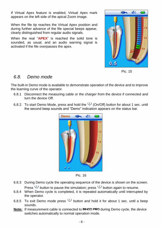
6.8. Demo mode
The built-in Demo mode is available to demonstrate operation of the device and to improve the learning curve of the operator.
6.8.1 Disconnect the measuring cable or the charger from the device if connected and turn the device Off.
6.8.2. To start Demo Mode, press and hold the (On/Off) button for about 1 sec. until the second beep sounds and “Demo” indication appears on the status bar.
6.8.3 During Demo cycle the operating sequence of the device is shown on the screen.
Press button to pause the simulation; press button again to resume. 6.8.4 When Demo cycle is completed, it is repeated automatically until interrupted by
the operator.
6.8.5 To exit Demo mode press button and hold it for about 1 sec. until a beep sounds.
Note: If measurement cable is connected to during Demo cycle, the device
switches automatically to normal operation mode.
Pic. 16
Pic. 15

- 9 -
6.9. Automatic Shutdown
automatically shuts down after 5 minutes without use. In order to prolong the battery life, it is recommended to switch OFF the device after measuring by pressing the
key (On/Off).
7. Battery Charging
The is delivered with a rechargeable battery.
Battery indicator on the status bar shows the battery charge level. When the icon is flashing, the battery requires recharging, however, it is still functional for several treatments before the device shuts down.
To charge the battery:
● Disconnect the measurement cable.
● Connect the charger to the mains.
● Connect the charger cable to the .
Charging screen will appear during battery charging. Running battery icon animation indicates charging in process. When the animation on the screen stops and the battery image turns fully green, the charging is complete.
Charging Charging is completed
Duration of charging: About 12 hours (24 hours after long periods without use).
Note: cannot be used while charging.
Warning: Use only original battery pack from your supplier!

- 10 -
7.1. Battery Replacement
The battery compartment is located at the bottom of and its cover is secured by a screw.
7.1.1. Release the screw and remove the battery compartment cover (Pic. 17).
7.1.2. Remove the battery from battery compartment and disconnect the battery cable
jack from the battery connector of (Pic. 18).
7.1.3. Insert the cable jack of the new battery into the battery connector.
7.1.4. Insert the battery into the battery compartment.
7.1.5. Close the battery compartment and secure the cover with the screw.
8. Maintenance, cleaning and sterilization
8.1. General
The device does not contain user serviceable parts. The service and repair should be provided by factory trained service personnel only.
All objects that were in contact with potentially infectious agents should be cleaned after each use:
Lip Clip, File Clip and Touch Probe should be disinfected and sterilized by autoclaving
between treatments. Please follow “Disinfection and sterilization procedure” described in section 8.2.
Measurement cable and the device should be cleaned using tissue or soft cloth
impregnated with aldehyde free disinfecting and detergent solution (a bactericidal and fungicidal).
The measuring cable cannot be autoclaved.
Use of agents other than specified above may cause damage to the equipment and its accessories
Pic. 17 Pic.18
- 11 -
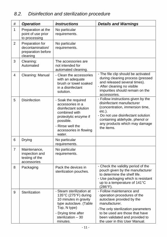
8.2. Disinfection and sterilization procedure
# Operation Instructions Details and Warnings
1 Preparation at the point of use prior to processing
No particular requirements.
2 Preparation for decontamination/ preparation before cleaning
No particular requirements.
3 Cleaning: Automated
The accessories are not intended for automated cleaning.
4 Cleaning: Manual - Clean the accessories with an adequate brush or towel soaked in a disinfectant solution.
- The file clip should be activated during cleaning process (pressed and released several times).
- After cleaning no visible impurities should remain on the accessories.
5 Disinfection - Soak the required accessories in a disinfectant solution combined with proteolytic enzyme if possible.
- Rinse well the accessories in flowing water.
- Follow instructions given by the disinfectant manufacturer (concentration, immersion time, etc.).
- Do not use disinfectant solution containing aldehyde, phenol or any products which may damage the items.
6 Drying No particular requirements.
7 Maintenance, inspection and testing of the accessories
No particular requirements.
8 Packaging Pack the devices in sterilization pouches.
- Check the validity period of the pouch given by the manufacturer to determine the shelf life.
- Use packaging which is resistant up to a temperature of 141°C (286°F).
9 Sterilization - Steam sterilization at 135°C (275°F) during 10 minutes in gravity type autoclave. (Table Top, N type)
- Drying time after sterilization – 30 minutes.
- Follow maintenance and operation procedures of the autoclave provided by the manufacturer.
-The only sterilization parameters to be used are those that have been validated and provided to the user in this User Manual.

- 12 -
# Operation Instructions Details and Warnings
10 Storage - Keep devices in sterilization packaging in a dry and clean environment.
- Sterility cannot be guaranteed if packaging is open or damaged (check the packaging before using the instruments).
9. Troubleshooting
Please review the suggested solutions before calling customer service.
# Problem Possible Cause Solution
1 The device shows the following picture during charging.
The battery is not connected.
Open the battery compartment, and connect the battery as described in the User Manual, section 7.1.
Warning:
Use only original battery pack from your supplier!
2 The device does not turn on by pressing On/Off button.
1. The button may be functioning incorrectly.
2. The battery may be empty.
3. Electronic malfunction.
1. Press the On/OFF button for several times.
2. Charge the battery.
3. Contact your customer service.
3 The device shuts off while measuring.
The battery is empty. Charge the battery.
4 No sound while measuring. “Sound control” set at “Mute” level.
Adjust the sound level by pressing the “Sound Control” button.
5 The device does not show file advance inside the canal
1. Bad electrical contact.
2. Electronic malfunction.
1. Perform cable connection test as described in the User Manual, section 6.4.
2. Contact your customer service.
# Problem Possible Cause Solution

- 13 -
6 Incorrect measurements 1. Dry/calcified canal.
2. Restoration
treatment conductive pass is blocked.
3. Spillage of blood
or irrigating liquid provide conductive path outside the canal.
4. Deep caries
provides conductive path outside the canal.
5. Metal crown or
metal filling provide conductive path outside the canal.
6. Perforation. 7. Large lateral
canal.
1. Irrigate the canal.
2. Remove old canal filling to open the path, irrigate the canal.
3. Dry the excessive
liquid. 4. Block the external
conductive path. 5. Avoid contact
between the file and metal crown/filling.
6. Remove the file,
close the perforation and repeat the measurements, carefully inserting the file into canal.
7. Try to continue the
measurements (gently advance the file towards apex until regular readings appear).
10. Warranty
is warranted for 24 months from the date of purchase. The accessories (cables, battery etc.) are warranted for 6 months from the date of purchase.
The warranty is valid for normal usage conditions. Any damage caused by accident, abuse, misuse, or as a result of service or modification other than by a person authorized by the manufacturer will render the warranty void. The warranty is in lieu of any other warranty expressed or implied.

- 14 -
11. Disclaimer
The manufacturer, its representatives and its dealers shall have no liability or responsibility to customers or any other person or entity with respect to any liability, loss or damage caused or alleged to be caused directly or indirectly by equipment sold or furnished by us, including, but not limited to, any interruption of service, loss of business or anticipatory profits, or consequential damages resulting from the use or operation of the equipment. The manufacturer reserves the right to implement changes and modifications of the product at any time, to revise this publication and to make changes in the contents hereof without obligation to notify any person of such changes, modifications or revisions.
12. Certification
complies with the following standards: IEC 60601-1 (Safety) and IEC 60601-1-2 (Electromagnetic compatibility), including conducted and radiated immunity tests as specified for equipment of Group 1 Class B.
is covered by the “CE Marking of Conformity” certificate. The device bears the following CE identification mark:
0344
13. European Authorized Representative
European Authorized Representative who has been empowered to enter into commitments in our behalf:
EASYDENT 13 Place de la Nation 75011 Paris, France. Tel. & Fax 33. 1.43.73.62.10 R.C.S. Paris B 397 769 480 (94B09899) Email: [email protected] President: Iris BAT-GENSTEIN

- 15 -
14. Technical Specifications
electronic apex locator belongs to the following category of medical devices:
- Internally powered equipment (2.4V NiMH rechargeable battery)
- Type BF applied parts
- Not suitable for use in the presence of flammable anesthetic mixtures with air, oxygen or nitrous oxide
- Continuous operation
- Ingress of liquids – not protected
- The device is intended for indoor use only
- Environmental conditions during transportation: temperature: –20ºC to +60ºC
(0 to 140ºF); relative humidity: 10% to 90%, non-condensing
is intended for use in electromagnetic environment specified for equipment of Group 1 Class B. Specifications:
Dimensions: 120 x 74 x 70 mm Weight: 300 gr. Type of screen: Color Graphic TFT Screen dimensions: 3.5” Supply: 2.4V NiMH rechargeable battery External charger: Input: 230V / 50-60 Hz or 120 V / 50-60 Hz Output: 6V DC
15. Standard symbols
On the device label appear standard symbols as follows:
Class II equipment
Consult instructions for use
Direct current
Type BF applied part
Recycling : PLEASE DO NOT THROW AWAY! This product and all its components must be recycled through your supplier
Manufacturer
Caution: Federal law restricts this device to sale by or on the order of a physician or licensed dental practitioner.

- 16 -

BINGO PRO Rev. 06 – 05/2015
Forum Engineering Technologies (96) Ltd.
1 Platin St., New Industrial Zone,
Rishon Lezion 7565339, Israel Tel :972-3-9625517 Fax :972-3-9613355
www.forumtec.net E-mail :[email protected]