AP1000 Plant Overview - IEEE Entity Web Hosting | A free...
35
Slide 1 AP1000 Plant Overview Westinghouse IEEE Subcommittee on Qualification Tom Hayes Passive Plant Projects [email protected] 1-412-374-4420
-
Upload
nguyenkien -
Category
Documents
-
view
216 -
download
0
Transcript of AP1000 Plant Overview - IEEE Entity Web Hosting | A free...

Slide 1
AP1000 Plant OverviewWestinghouse
IEEE Subcommittee on Qualification
Tom HayesPassive Plant Projects

Slide 2
Westinghouse Passive Plants Meet Power Company Needs
Satisfies all U.S. Utility Requirements (ALWR URD)0Cost, construction, operations advantages demonstrated
Major Simplifications Achieved0Construction, design, maintenance & operations
Provides New Standard in Safety0Improved safety and risk performance, margins verified
Licensing Certainty0Rigorous NRC review & comprehensive test program0Assures licensibility for domestic & international sites

Slide 3
Design Bounded By:
Make it safeMeet US regulatory requirementsSatisfy utility requirementsMake it simpleUse proven technologyMake safety systems passiveMake it affordable

Slide 4
Naturally Occurring Physical Phenomena Used in Operation of Safety Systems
Natural circulation of air, water, and steamGravity and gas pressure drive flow of cooling water.Natural heat transfer through conduction, convection, and evaporationFlow and cooling occur in accordance with nature’s laws - No support systemsOne time alignment of active valves (dc battery actuated) 0No dc actuation power after 24 hours
Greatly reduced operator dependency

Slide 5
AP1000 Approach to Safety
Passive Safety Systems0Use “passive” process only, no active pumps, diesels, ….
0 One time alignment of valves
0 No support systems required after actuation
0Reduced dependency on operator actions0Mitigate design basis accidents without nonsafety systems0Meet NRC safety goals without use of nonsafety systems
Active Nonsafety Systems0Reliably support normal operation
0 Redundant equipment powered by onsite diesels
0Minimize challenges to passive safety systems0Not required to mitigate design basis accidents

Slide 6
Major Safety AdvancementsNo Reliance on AC Power
No Operator Action Required to Assure Safety
Long Term Plant Safety Assured without Active Components (Natural Forces Only)
Containment is Not Breached for Postulated Design Basis Events
In Severe Accidents, Reactor Vessel Cooling Keeps Core in Vessel
Large Margin to Safety Limits
Defense in Depth - Active Systems Provide ADDITIONAL first line of defense

Slide 7
AP1000 Design Features
Integrated Power Plant DesignSimplified RCS Loops with Canned Motor PumpsSimplified Passive Safety SystemsMicroprocessor, Digital Technology Based I&C No Requirement for Safety AC PowerCompact Control Room, Electronic Operator InterfaceOptimized Plant Arrangement0 Construction, Operation, Maintenance, Safety, Cost
Extensive Use of Modular Construction

Slide 8
Approach to Safety: Defense-in-DepthSimple Passive Safety Systems• Dedicated safety systems - not required for normal operation
• Use “natural” driving forces - no active pumps, diesels
• One-time alignment of active valves
• No support systems after actuation
• Reduced operator dependency
• Mitigate design basis accidents without nonsafety systems
Simple Active Non-Safety Systems• Reliable active equipment for normal operation
• Redundant active equipment powered by nonsafety diesels
• Minimize unnecessary use of passive safety systems
• Reduce risk to utility & public

Slide 9
Simplicity Applies to Every Element of the AP1000/AP600
Simplicity in Design through reduced number of components and bulk commodities
Simplicity in Safety through use of passive safety systems
Simplicity in Procurement through standardization of components
Simplicity in Operation and Maintenance through use of proven systems and components and man-machine interface advancements

Slide 10
Passive Safety Features:Eliminate the Need for Safety AC Electric Power
Passive Decay Heat Removal• Natural circulation heat exchanger connected to Reactor Coolant System
(RCS)
Passive Safety Injection• Gravity drain core makeup tanks (RCS pressure)
• N2 pressurized accumulators
• Gravity drain refueling water storage tank (containment pressure)
• Automatic RCS depressurization
Passive Containment Cooling• Steel containment shell transfers heat to natural circulation of air and
evaporation of water drained by gravity
Passive Heating Ventilation Air Conditioning• Compressed air for habitability of main control room (MCR)
• Concrete walls for heat sink (MCR and C&I rooms)

Slide 11
Passive Containment Cooling
Slide 12
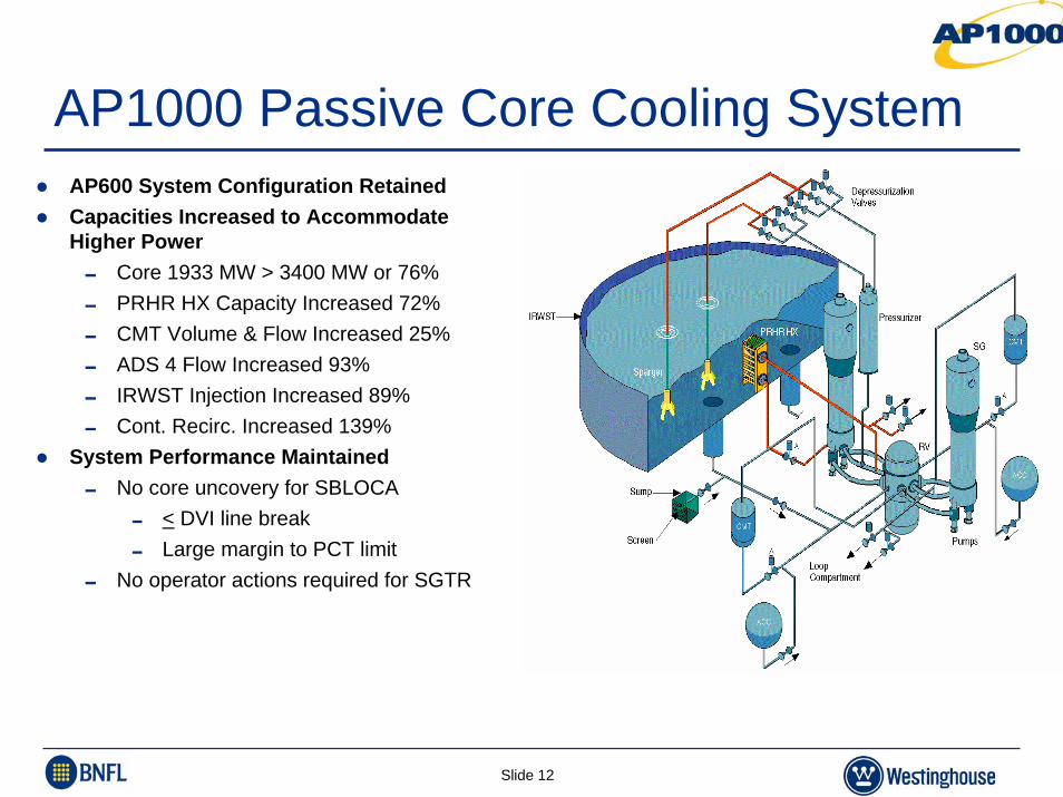
AP1000 Passive Core Cooling SystemAP600 System Configuration RetainedCapacities Increased to Accommodate Higher Power 0 Core 1933 MW > 3400 MW or 76%0 PRHR HX Capacity Increased 72%0 CMT Volume & Flow Increased 25%0 ADS 4 Flow Increased 93%0 IRWST Injection Increased 89%0 Cont. Recirc. Increased 139%
System Performance Maintained0 No core uncovery for SBLOCA
0 < DVI line break0 Large margin to PCT limit
0 No operator actions required for SGTR

Slide 13
AP1000 EHVAC MCRCompressed air provides breathable air for operators0 72 hours of operation0 65 SCFM air flow pressurizes MCF 1/8 in water
Thermal mass of concrete provides temperature control
MAIN CONTROL ROOM
NORMAL HVAC
COMPRESSEDAIR TANKS
FC
FC
FC
FC
(1 of 8)
(1 of 8)
(1 of 8)
(1 of 8)
CompressedAir System
FC
FC

Slide 14
Approach to Safety: Defense-in-DepthSimple Passive Safety Systems• Dedicated safety systems - not required for normal operation
• Use “natural” driving forces - no active pumps, diesels
• One-time alignment of active valves
• No support systems after actuation
• Reduced operator dependency
• Mitigate design basis accidents without nonsafety systems
Simple Active Non-Safety Systems• Reliable active equipment for normal operation
• Redundant active equipment powered by nonsafety diesels
• Minimize unnecessary use of passive safety systems
• Reduce risk to utility & public

Slide 15
Active Nonsafety SystemsActive Nonsafety System Functions0 Reliably support normal operation
0 Minimize challenge to passive safety systems
0 Not required to mitigate design basis accidents
0 Not required to meet NRC safety goals
Active Nonsafety System Design Features0 Redundancy to minimize failures effects
0 Automatic actuation with power from onsite diesels
Active Nonsafety System Equipment Design0 Reliable industrial grade equipment
0 Non-ASME, non-seismic, limited fire / flood / wind protection
0 Availability controlled by procedures, no shutdown requirements
0 Reliability controlled by maintenance program (not maintenance rule)

Slide 16
System Defense In Depth
AP1000 Provides Multiple Levels of Defense0First feature is usually nonsafety active feature0 High quality industrial grade equipment
0One feature is safety passive feature0 Provides safety case for DCD
0 Highest quality nuclear grade equipment
0Other passive features provide additional defense-in-depth0 Example; passive feed/bleed backs up PRHR HX
0Available for all shutdown conditions as well as at power
0More likely events have more levels of defense

Slide 17
Passive Safety SystemsPassive Safety System Functions0 Dedicated safety systems, not used for normal operation0 Mitigate design basis accidents without nonsafety systems0 Meet NRC safety goals without use of nonsafety systems
Passive Safety System Design Features0 Only passive processes; no active pumps, diesels, fans, …0 DBA considerations; margin, single failure0 PRA considerations; reliability, common mode failures0 Reduced dependency on operator actions
Passive Safety System Equipment Design0 Reliable, experienced based, nuclear grade equipment0 ASME, seismic I, full fire / flood / wind protection0 Availability controlled by Tech Spec with shutdown requirements0 Reliability controlled by ISI / IST and maintenance program

Slide 18
Active Nonsafety SystemsActive Nonsafety System Functions0 Reliably support normal operation0 Minimize challenge to passive safety systems0 Not required to mitigate design basis accidents0 Not required to meet NRC safety goals
Active Nonsafety System Design Features0 Simplified designs (fewer components, separation not required)0 Redundancy for more probable failures0 Automatic actuation with power from onsite diesels
Active Nonsafety System Equipment Design0 Reliable, experienced based, industrial grade equipment0 Non-ASME, non-seismic, limited fire / flood / wind protection0 Availability controlled by procedures, no shutdown requirements0 Reliability controlled by maintenance program0 Quality Class D used for components that minimize challenges to
passive systems
Slide 19
AP1000 Electrical Systems
Class 1E DC and UPS System (IDS)0 Provides electrical power to safety components
Non-Class 1E DC and UPS System (EDS)0 Provides electrical power to non-safety components requiring
highly-reliable power
Main AC Power System (ECS)0 Provides bulk electrical power
Onsite Standby Power System (ZOS)0 Provides electrical power to defense-in-depth and investment
protection loads when offsite power is lost

Slide 20
AP1000 Class 1E DC & UPS System (IDS)
125 Vdc120/208Vac 60 Hz (uninterruptible)Four Divisions0 Divisions A and D each have one 24-hour battery
for actuation0 Divisions B and C each have one 24-hour battery
and one 72- hour battery for post-accident monitoring
0 72-hour battery is for monitoring only0 Spare battery
0 Can be manually connected to replace any of the 6 primary batteries

Slide 21
AP1000 Class 1E DC & UPS System (IDS)
Provides electrical power to safety components0 Primary Protection System0 MCR lighting0 Valve actuators0 Reactor trip, RCP trip
Class 1E0 Meets IEEE 308, 323, 344, 379, 384, 603, etc.
Slide 22
AP1000 Non-Class 1E DC & UPS System (EDS)
125 Vdc120/208Vac 60 Hz (uninterruptible)Two load groups0 Each group has two 2-hour batteries0 The IDS spare battery can be used to replace any
of the 4 primary nonsafety batteries

Slide 23
AP1000 Non-Class 1E DC & UPS System (EDS)
Provides electrical power to non-safety components requiring highly-reliable power0 Plant Control System
0 Data Display System
0 Diverse Actuation System
0 Other control systems
0 Communications
0 Hydrogen igniters
Non-Class 1E0 Quality Class D
0 RTNSS Important (portions)

Slide 24
AP1000 Main AC Power System (ECS)Provides bulk electrical power0 6.9 kV, 480 V, 120/208 V, 60 Hz
Normal power supply from main generatorPreferred power supply is offsite source through main and auxiliary transformersMaintenance power supply is through reserve auxiliary transformerStandby power source is two diesel generatorsTwo load groups0 Each group is connected to one standby diesel generator, one
auxiliary transformer and the reserve auxiliary transformer

Slide 25
AP1000 Main AC Power System (ECS)
Includes two ancillary diesel generators (35 kW each) for post-72-hour coping0 Post-accident monitoring instrumentation
0 Control room lighting
0 Passive containment cooling tank refill
0 Spent fuel pool refill
Non-Class 1E0 Equipment Class D (portions)
0 RTNSS Important (portions)

Slide 26
Onsite Standby Power System (ZOS)
Two diesel generators (4000 kW each)Provides electrical power to defense-in-depth and investment protection loads when offsite power is lost Non-Class 1E0 Quality Class D
0 RTNSS Important

Slide 27
AP1000 I&C Systems
Primary Protection System (PMS)0 Plant wide system for all safety displays & controls0 Microprocessor / software based
Diverse System (DAS)0 Limited scope system, PRA based displays & controls0 Backs up PMS where common mode failure is risk important0 Different hardware & software than PMS
Plant Control System (PLS/DDS)0 Plant wide system for all normal displays & controls0 Microprocessor / software based
Special Purpose Systems (Seismic Monitoring, Radiation Monitoring, Incore Instrumentation, etc.)

Slide 28
AP1000 I&C SystemsLicensing Status
I&C systems are included in Certified Design.I&C system designs were not reviewed by the NRC.Functional requirements consistent with the safety analyses and PRA were established.A design process was defined.Test and acceptance criteria were established.A conceptual design was developed.A detailed I&C design will be developed based on the functional requirements, using the certified design process, and meeting the certified acceptance requirements after a plant is ordered.
Slide 29
AP1000 Protection System (PMS)
Plant-wide Class 1E system for all safety displays & controlsOriginally expected to be ‘Eagle’, now expected to be ‘Common Q’Detects off-nominal conditions and actuates safety functionsProvides post-accident monitoring functions0 Regulatory Guide 1.97 Category 1 and some Category 2
variablesMicroprocessor / software basedMultiplexed communicationsClass 1E0 Meets IEEE-603, 7-4.3.2, 323, 344, 379, 384, etc.
Slide 30
AP1000 Protection System (PMS)Redundant Trains0 4 divisions, physically separated with electrical isolation (fiber-
optic)0 Each with own independent battery-backed power supply0 24-hour batteries for actuation, 72-hour batteries for monitoring0 Improved HVAC separation/fire protection (2 separate HVAC systems)
0 2-out-of-4 bypass logic, fail safe when appropriate0 Different plant parameters provide functional diversity
Verification and ValidationEquipment Qualification0 Environmental, seismic, EMC
Improved In-Plant Testing0 Built-in continuous self-testing and manual periodic testing
Westinghouse Extensive Experience with Digital I&C Designs0 Operating plant upgrades and new plants (Sizewell, Temelin)

Slide 31
AP1000 Diverse Actuation System (DAS)
Limited scope system0 PRA-based displays & controls0 Backs up PMS where common mode failure is risk important
Microprocessor / software based Different architecture, hardware & software than PMSNo multiplexingManual controls and indications use no software0 Direct wiring to actuation devices0 Compliance with USNRC Branch Technical Position HICB-19,
Position 4
Separate sensors from PMS and PLS

Slide 32
AP1000 Diverse Actuation System (DAS)
DAS shares some actuated equipment (e.g., valves) with PMS0 DAS signals isolated from PMS
0 Separate actuation devices0 Solenoid valves on AOVs0 Igniters on squib valves0 Relays in MCCs controlling AOVs
Non-Class 1E0 Equipment Class D0 RTNSS Important

Slide 33
AP1000 Control System (PLS / DDS)
Plant-wide system for all normal displays & controlsMicroprocessor / software basedHighly redundantContinuously usedMultiplexed communicationsIncludes plant computer functionsNon-Class 1E0 Equipment Class D

Slide 34
AP1000 Advanced Control RoomCompact Control Room0 Designed for 1 Reactor Operator and 1 Supervisor
Displays0 Plant status / overview via wall panel (DDS, non 1E)
0 Detail display via workstation video displays (DDS, non 1E)
0 Small number of dedicated displays; safety (PMS, 1E) & diverse (DAS, non 1E)
Controls0 Soft controls (DDS, non 1E)
0 Small number of dedicated
switches; safety (PMS, 1E) &
diverse (DAS, non 1E)
Advanced Alarm Management
Computer Based Procedures0 Paper backup
Slide 35
AP1000 is DifferentSafety systems are not used for normal operation.0 Multiple, diverse levels of defense0 Signals from safety sensors are provided to nonsafety system.
No safety source of electrical power.0 Batteries provided for I&C and lighting.
No safety actuation power after 24 hours without ac power.0 Planned safety actuations are one-time-only.
Batteries provided for monitoring are sized for 72 hours.0 Small non-safety diesels provided for post-72 hour monitoring and water.
No safety air conditioning.Safety motors are limited to MOV operators.Compact control room.0 Limited number of discrete controls