ANTI-LOCK BRAKE SYSTEM - REAR WHEEL - telus.net Tech Info/91-95/anti lock brake... · ANTI-LOCK...
18
ANTI-LOCK BRAKE SYSTEM - REAR WHEEL 1994 Nissan Pickup 1994 BRAKES Nissan - Rear Anti-Lock Pathfinder, Pickup DESCRIPTION In 2WD mode, Rear Anti-Lock Brake System (RABS) helps the driver to maintain steering control during heavy braking by fluctuating rear brakeline pressure. This prevents rear wheel lock-up and skidding in the event of front wheel lock-up. In 4WD mode, RABS will not prevent rear wheel lock-up if front wheels lock. System consists of an Electronic Control Unit (ECU) with an LED that displays self-diagnostic codes, a rear wheel speed sensor, actuator (electro-hydraulic unit) and an ANTI-LOCK warning light located on instrument cluster. See Fig. 1. See RABS ELECTRICAL COMPONENT LOCATIONS table. ANTI-LOCK warning light warns driver of problem in ABS. If test terminal of check connector is grounded when warning light is on, LED on ECU will flash to indicate trouble codes. See Fig. 4. RABS ELECTRICAL COMPONENT LOCATIONS TABLE Component Location ECU .................... Behind Center Of Instrument Panel Ignition Relay No. 2 ..................... Below Passenger Compartment Fuse Block Rear Wheel Speed Sensor ... On Differential Companion Flange NOTE: For more brake system information, see BRAKE SYSTEM article in the BRAKES section. BRAKE SYSTEM - Pathfinder BRAKE SYSTEM - Pickup Fig. 1: Locating Rear Anti-Lock Brake System Components Courtesy of Nissan Motor Co., U.S.A.
Transcript of ANTI-LOCK BRAKE SYSTEM - REAR WHEEL - telus.net Tech Info/91-95/anti lock brake... · ANTI-LOCK...
ANTI-LOCK BRAKE SYSTEM - REAR WHEEL
1994 Nissan Pickup
1994 BRAKES Nissan - Rear Anti-Lock
Pathfinder, Pickup
DESCRIPTION
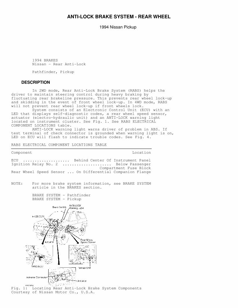
In 2WD mode, Rear Anti-Lock Brake System (RABS) helps thedriver to maintain steering control during heavy braking byfluctuating rear brakeline pressure. This prevents rear wheel lock-upand skidding in the event of front wheel lock-up. In 4WD mode, RABSwill not prevent rear wheel lock-up if front wheels lock. System consists of an Electronic Control Unit (ECU) with anLED that displays self-diagnostic codes, a rear wheel speed sensor,actuator (electro-hydraulic unit) and an ANTI-LOCK warning lightlocated on instrument cluster. See Fig. 1. See RABS ELECTRICALCOMPONENT LOCATIONS table. ANTI-LOCK warning light warns driver of problem in ABS. Iftest terminal of check connector is grounded when warning light is on,LED on ECU will flash to indicate trouble codes. See Fig. 4.
RABS ELECTRICAL COMPONENT LOCATIONS TABLE�����������������������������������������������������������������������������������������������������������������������Component Location
ECU .................... Behind Center Of Instrument PanelIgnition Relay No. 2 ..................... Below Passenger Compartment Fuse BlockRear Wheel Speed Sensor ... On Differential Companion Flange�����������������������������������������������������������������������������������������������������������������������
NOTE: For more brake system information, see BRAKE SYSTEM article in the BRAKES section.
BRAKE SYSTEM - Pathfinder BRAKE SYSTEM - Pickup
Fig. 1: Locating Rear Anti-Lock Brake System ComponentsCourtesy of Nissan Motor Co., U.S.A.
OPERATION
NOTE: In 4WD mode, rear wheels will lock if front wheels lock. If this occurs, ANTI-LOCK warning light will come on. This is not a malfunction. Warning light will reset if engine is turned off and then started again.
When vehicle is moving, rear wheel speed sensor sends an ACsignal to the ECU. When brake pedal is applied, ECU receives signalthrough brakelight switch. When this occurs, ECU will monitordeceleration rate of rear wheels through rear wheel speed sensor.Sensor is located on front of rear differential. See Figs. 1 and 8. If rear wheel deceleration rate reaches a preprogrammed rate(with vehicle in 2WD mode), the ECU activates the solenoid valvesinside the actuator (electro-hydraulic unit). Solenoid valves arecycled to apply, release or maintain hydraulic pressure to each rearwheel brake caliper/wheel cylinder depending upon signals from ECU.Regulating hydraulic pressure to each caliper/wheel cylinder preventsrear wheel lock-up. When brake pedal is released, ECU deactivatessolenoid valves, and system returns to conventional brake systemoperation until ABS is needed.
CAUTION: See ANTI-LOCK BRAKE SAFETY PRECAUTIONS article in the GENERAL INFORMATION section.
BLEEDING BRAKE SYSTEM
Turn ignition off. Disconnect actuator connectors. Bleedbrake system in a conventional manner using the following sequence:
* Left rear caliper or wheel cylinder. * Right rear caliper or wheel cylinder. * Left front caliper. * Right front caliper and bleeder on RABS actuator.
ADJUSTMENTS
BRAKE PEDAL HEIGHT & FREE PLAY
1) Lift up carpet and insulator. Measure pedal height frompressure face of pedal pad to floor pan. If pedal height is not asspecified, loosen brake booster input rod lock nut. See BRAKE PEDALHEIGHT SPECIFICATIONS table. 2) Rotate input rod to obtain proper pedal height. Tightenlock nut. Adjust brakelight switch. See BRAKELIGHT & CRUISE CONTROLSWITCHES under ADJUSTMENTS. Ensure pedal free play is .04-.12" (1.0-3.0 mm).
BRAKE PEDAL HEIGHT SPECIFICATIONS TABLE�����������������������������������������������������������������������������������������������������������������������Application In. (mm)
Automatic Transmission ........... 8.35-8.74 (212.0-222.0)Manual Transmission .............. 8.23-8.62 (209.0-219.0)�����������������������������������������������������������������������������������������������������������������������
LOAD-SENSING PROPORTIONING VALVE
NOTE: If pressure cannot be adjusted to specification, replace
entire valve assembly.
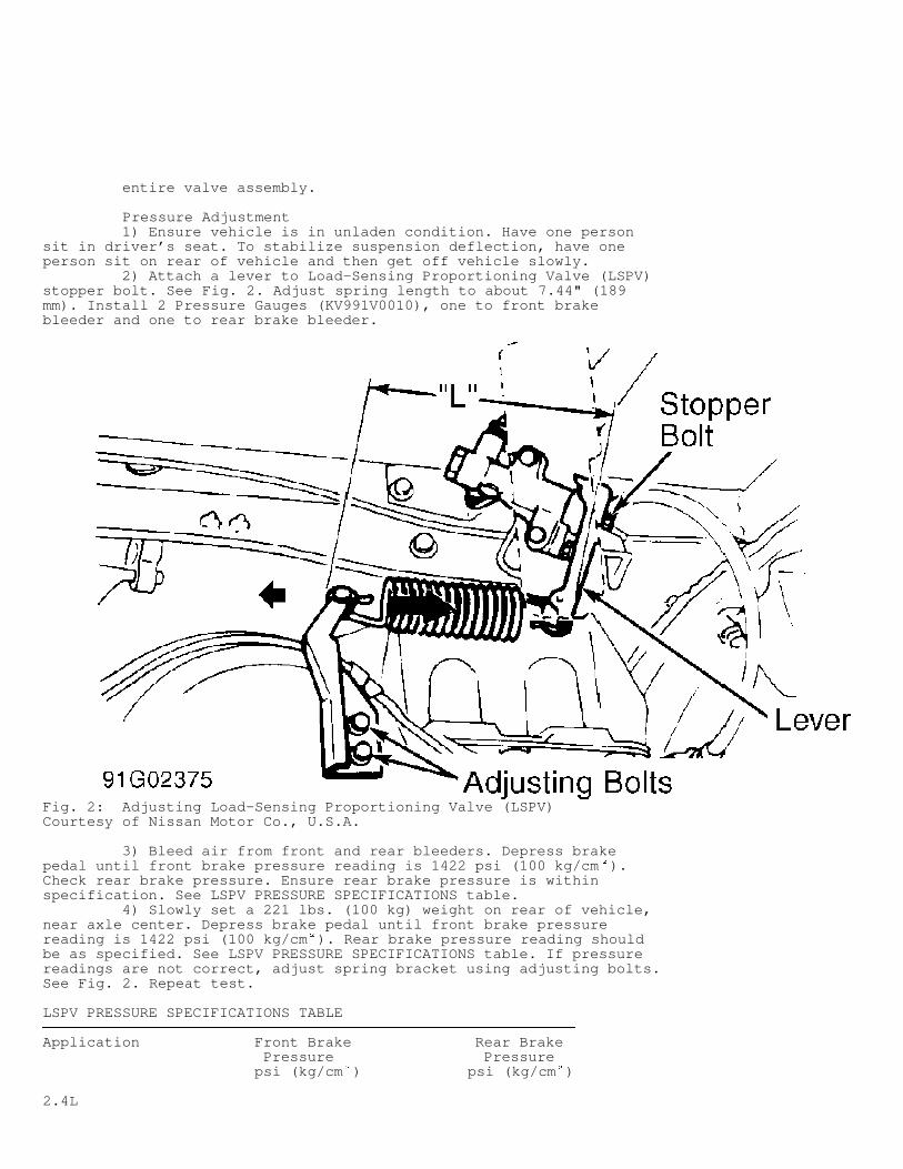
Pressure Adjustment 1) Ensure vehicle is in unladen condition. Have one personsit in driver’s seat. To stabilize suspension deflection, have oneperson sit on rear of vehicle and then get off vehicle slowly. 2) Attach a lever to Load-Sensing Proportioning Valve (LSPV)stopper bolt. See Fig. 2. Adjust spring length to about 7.44" (189mm). Install 2 Pressure Gauges (KV991V0010), one to front brakebleeder and one to rear brake bleeder.
Fig. 2: Adjusting Load-Sensing Proportioning Valve (LSPV)Courtesy of Nissan Motor Co., U.S.A.
3) Bleed air from front and rear bleeders. Depress brakepedal until front brake pressure reading is 1422 psi (100 kg/cm
�).
Check rear brake pressure. Ensure rear brake pressure is withinspecification. See LSPV PRESSURE SPECIFICATIONS table. 4) Slowly set a 221 lbs. (100 kg) weight on rear of vehicle,near axle center. Depress brake pedal until front brake pressurereading is 1422 psi (100 kg/cm
�). Rear brake pressure reading should
be as specified. See LSPV PRESSURE SPECIFICATIONS table. If pressurereadings are not correct, adjust spring bracket using adjusting bolts.See Fig. 2. Repeat test.
LSPV PRESSURE SPECIFICATIONS TABLE�����������������������������������������������������������������������������������������������������������������������Application Front Brake Rear Brake Pressure Pressure psi (kg/cm
�) psi (kg/cm
�)
2.4L
With Weight (1) ..... 1422 (100) ... (2) 498-697 (36-49) Without Weight ...... 1422 (100) ...... 427-540 (30-38)3.0L Except Heavy Duty With Weight (1) ..... 1422 (100) ...... 597-796 (42-56) Without Weight ...... 1422 (100) ...... 441-555 (31-39) Heavy Duty With Weight (1) ..... 1422 (100) ...... 569-768 (40-54) Without Weight ...... 1422 (100) ...... 441-555 (31-39)
(1) - Weight is 221 lbs. (100 kg) above rear axle center.(2) - 483-683 psi (34-48 kg/cm
�) for Canadian vehicles.
�����������������������������������������������������������������������������������������������������������������������
PARKING BRAKE
Adjustment (Rear Disc Brake) 1) Release parking brake lever. Using a screwdriver, rotateparking brake shoe adjuster wheel until parking brake shoes contactdrum. Back off adjuster wheel 7-8 notches. Ensure shoes do not drag ondrum. 2) Raise and support rear of vehicle. Cable adjuster is undervehicle. Turn cable adjuster until parking brake lever can be pulledup the appropriate number of strokes (notches) with 44 lbs. (20 kg) offorce applied to lever. See PARKING BRAKE LEVER STROKE SPECIFICATIONStable. After releasing lever, ensure rear wheels rotate freely.
PARKING BRAKE LEVER STROKE SPECIFICATIONS TABLE�����������������������������������������������������������������������������������������������������������������������Application Notches
Pathfinder ........................................... 7-9Pickup Center Lever Type ................................. 10-12 Stick Lever Type 2WD .............................................. 10-12 4WD ............................................... 9-11�����������������������������������������������������������������������������������������������������������������������
Adjustment (Rear Drum Brake) Raise and support rear of vehicle. Adjust brake shoe-to-drumclearance. Cable adjuster is under vehicle. Turn cable adjuster untilparking brake lever can be pulled up appropriate number of strokes(notches) with 44 lbs. (20 kg) of force applied to lever. See PARKINGBRAKE LEVER STROKE SPECIFICATIONS table. After releasing lever, ensurerear wheels rotate freely.
POWER BRAKE UNIT OUTPUT ROD
Apply 20 in. Hg vacuum to power brake unit with hand-heldvacuum pump. See Fig. 3. Measure length of output rod extending frompower brake unit housing. Adjust output rod if length is not .40-.41"(10.3-10.5 mm). If length cannot be adjusted, replace power brakeunit.
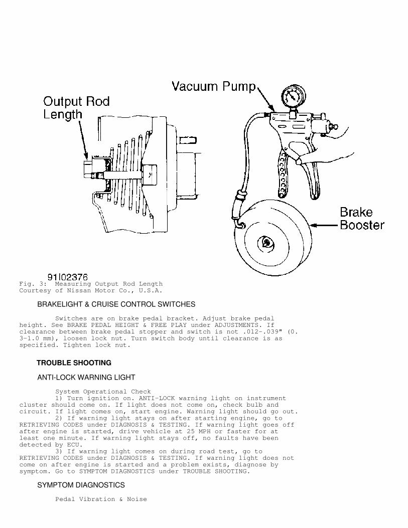
Fig. 3: Measuring Output Rod LengthCourtesy of Nissan Motor Co., U.S.A.
BRAKELIGHT & CRUISE CONTROL SWITCHES
Switches are on brake pedal bracket. Adjust brake pedalheight. See BRAKE PEDAL HEIGHT & FREE PLAY under ADJUSTMENTS. Ifclearance between brake pedal stopper and switch is not .012-.039" (0.3-1.0 mm), loosen lock nut. Turn switch body until clearance is asspecified. Tighten lock nut.
TROUBLE SHOOTING
ANTI-LOCK WARNING LIGHT
System Operational Check 1) Turn ignition on. ANTI-LOCK warning light on instrumentcluster should come on. If light does not come on, check bulb andcircuit. If light comes on, start engine. Warning light should go out. 2) If warning light stays on after starting engine, go toRETRIEVING CODES under DIAGNOSIS & TESTING. If warning light goes offafter engine is started, drive vehicle at 25 MPH or faster for atleast one minute. If warning light stays off, no faults have beendetected by ECU. 3) If warning light comes on during road test, go toRETRIEVING CODES under DIAGNOSIS & TESTING. If warning light does notcome on after engine is started and a problem exists, diagnose bysymptom. Go to SYMPTOM DIAGNOSTICS under TROUBLE SHOOTING.
SYMPTOM DIAGNOSTICS
Pedal Vibration & Noise
1) If symptom appears only under sudden brake application,press pedal normally. If symptom is gone, RABS is okay. If symptomappears when brake is applied normally, go to next step. 2) If noise appears and warning light activates anddeactivates only when ignition is turned on, RABS is functioningcorrectly. If noise appears with ignition off, check brake pedal andhydraulic system.
Long Stopping Distance 1) Check road condition. If road condition is slippery orgravelly, stopping distance will be longer than normal. If roadcondition is not slippery or gravelly, disconnect actuator connector.Recheck stopping distance. 2) If stopping distance is still too long, inspect brakesystem and bleed hydraulic system. See BLEEDING BRAKE SYSTEM. Ifstopping distance is now normal, reconnect actuator connector. Go toPRELIMINARY INSPECTION under DIAGNOSIS & TESTING, and perform self-diagnostics.
Pedal Stroke Too Long Check frequency of symptom. If symptom appears occasionally,this may not be a malfunction indication (length of brake pedal stroketends to increase during RABS operation). If symptom appearsregularly, bleed hydraulic system. See BLEEDING BRAKE SYSTEM. Inspectcondition of brake mechanical components.
ABS Does Not Work 1) If ANTI-LOCK warning light comes on, go to PRELIMINARYINSPECTION under DIAGNOSIS & TESTING, and perform self-diagnostics. IfANTI-LOCK warning light does not come on, go to next step. 2) Ensure vehicle is not in 4WD mode, and vehicle speed isgreater than 6 MPH. RABS does not work in 4WD mode or at speeds lessthan 6 MPH. 3) Check parking brake switch and brakelight switch operationand adjustment. Replace or adjust switches as necessary. If parkingbrake switch and brakelight switch are okay and RABS still does notwork, go to next step. 4) Check actuator and rear wheel speed sensor. See ACTUATORand REAR WHEEL SPEED SENSOR under DIAGNOSIS & TESTING. Repair orreplace components as necessary. If actuator and speed sensor areokay, check ECU power and ground circuits. See ECU POWER & GROUNDCIRCUITS under DIAGNOSIS & TESTING. Repair as necessary. If ECU powerand ground circuits are okay, replace ECU.
ABS Works Frequently 1) Check brake fluid pressure differential. See PROPORTIONINGVALVE under DIAGNOSIS & TESTING. If pressure differential is okay, goto next step. If pressure differential is not to specification,replace master cylinder. 2) Check brake system thoroughly. Repair or replacecomponents as necessary. If brake system is okay, RABS should beoperating correctly.
NOTE: Frequent RABS operation is normal under severe braking conditions where wheel lock-up would occur.
DIAGNOSIS & TESTING
NOTE: To prevent terminal damage, backprobe terminals when connecting test meter leads to ECU connector.
PRELIMINARY INSPECTION
Preliminary Check No. 1 1) Turn ignition on. If ANTI-LOCK warning light comes on, goto next step. If warning light does not come on, check ECU power andground circuits. See ECU POWER & GROUND CIRCUITS under DIAGNOSIS &TESTING. If power and ground circuits are okay, replace ECU. 2) Wait a few seconds. If warning light goes out after a fewseconds and remains out, go to next step. If warning light remains on,or goes out and then comes on again, go to PRELIMINARY CHECK NO. 2. 3) Drive vehicle in 2WD mode at speeds greater than 25 MPHfor at least one minute. If warning light comes on during road test,go to PRELIMINARY CHECK NO. 2. If warning light does not come onduring road test, stop engine. 4) Turn ignition on and listen for actuator clicking whenwarning light goes out. If actuator clicks when warning light goesout, RABS is okay. If actuator does not click when warning light goesout, check actuator. See ACTUATOR under DIAGNOSIS & TESTING.
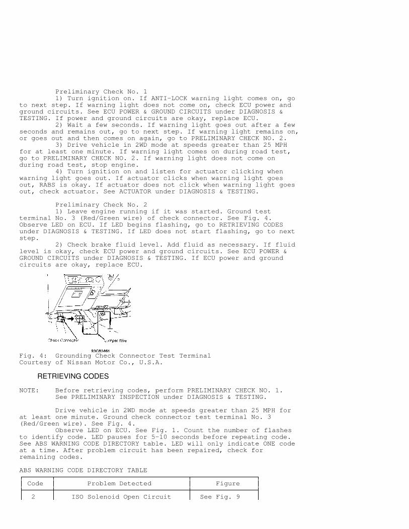
Preliminary Check No. 2 1) Leave engine running if it was started. Ground testterminal No. 3 (Red/Green wire) of check connector. See Fig. 4.Observe LED on ECU. If LED begins flashing, go to RETRIEVING CODESunder DIAGNOSIS & TESTING. If LED does not start flashing, go to nextstep. 2) Check brake fluid level. Add fluid as necessary. If fluidlevel is okay, check ECU power and ground circuits. See ECU POWER &GROUND CIRCUITS under DIAGNOSIS & TESTING. If ECU power and groundcircuits are okay, replace ECU.
Fig. 4: Grounding Check Connector Test TerminalCourtesy of Nissan Motor Co., U.S.A.
RETRIEVING CODES
NOTE: Before retrieving codes, perform PRELIMINARY CHECK NO. 1. See PRELIMINARY INSPECTION under DIAGNOSIS & TESTING.
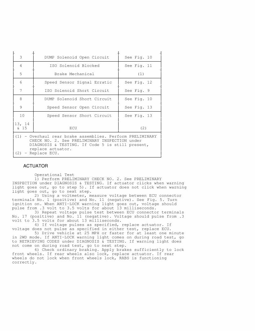
Drive vehicle in 2WD mode at speeds greater than 25 MPH forat least one minute. Ground check connector test terminal No. 3(Red/Green wire). See Fig. 4. Observe LED on ECU. See Fig. 1. Count the number of flashesto identify code. LED pauses for 5-10 seconds before repeating code.See ABS WARNING CODE DIRECTORY table. LED will only indicate ONE codeat a time. After problem circuit has been repaired, check forremaining codes.
ABS WARNING CODE DIRECTORY TABLE������������������������������������������������������������������������������������������������������������������������ Code
� Problem Detected
� Figure
�� ������������������������������������������������������������������������������������������������������������������� 2
� ISO Solenoid Open Circuit
� See Fig. 9
�
� ������������������������������������������������������������������������������������������������������������������� 3
� DUMP Solenoid Open Circuit
� See Fig. 10
�� ������������������������������������������������������������������������������������������������������������������� 4
� ISO Solenoid Blocked
� See Fig. 11
�� ������������������������������������������������������������������������������������������������������������������� 5
� Brake Mechanical
� (1)
�� ������������������������������������������������������������������������������������������������������������������� 6
� Speed Sensor Signal Erratic
� See Fig. 12
�� ������������������������������������������������������������������������������������������������������������������� 7
� ISO Solenoid Short Circuit
� See Fig. 9
�� ������������������������������������������������������������������������������������������������������������������� 8
� DUMP Solenoid Short Circuit
� See Fig. 10
�� ������������������������������������������������������������������������������������������������������������������� 9
� Speed Sensor Open Circuit
� See Fig. 13
�� ������������������������������������������������������������������������������������������������������������������� 10
� Speed Sensor Short Circuit
� See Fig. 13
�� �������������������������������������������������������������������������������������������������������������������13, 14
�
�
�� & 15
� ECU
� (2)
�� ���������������������������������������������������������������������������������������������������������������������(1) - Overhaul rear brake assemblies. Perform PRELIMINARY
�� CHECK NO. 2. See PRELIMINARY INSPECTION under
�� DIAGNOSIS & TESTING. If Code 5 is still present,
�� replace actuator.
��(2) - Replace ECU.
�� ��������������������������������������������������������������������������������������������������������������������
ACTUATOR
Operational Test 1) Perform PRELIMINARY CHECK NO. 2. See PRELIMINARYINSPECTION under DIAGNOSIS & TESTING. If actuator clicks when warninglight goes out, go to step 5). If actuator does not click when warninglight goes out, go to next step. 2) Using a voltmeter, measure voltage between ECU connectorterminals No. 1 (positive) and No. 11 (negative). See Fig. 5. Turnignition on. When ANTI-LOCK warning light goes out, voltage shouldpulse from .3 volt to 3.5 volts for about 13 milliseconds. 3) Repeat voltage pulse test between ECU connector terminalsNo. 17 (positive) and No. 11 (negative). Voltage should pulse from .3volt to 3.5 volts for about 13 milliseconds. 4) If voltage pulses as specified, replace actuator. Ifvoltage does not pulse as specified in either test, replace ECU. 5) Drive vehicle at 25 MPH or faster for at least one minutein 2WD mode. If ANTI-LOCK warning light comes on during road test, goto RETRIEVING CODES under DIAGNOSIS & TESTING. If warning light doesnot come on during road test, go to next step. 6) Check ordinary braking. Apply brakes sufficiently to lockfront wheels. If rear wheels also lock, replace actuator. If rearwheels do not lock when front wheels lock, RABS is functioningcorrectly.
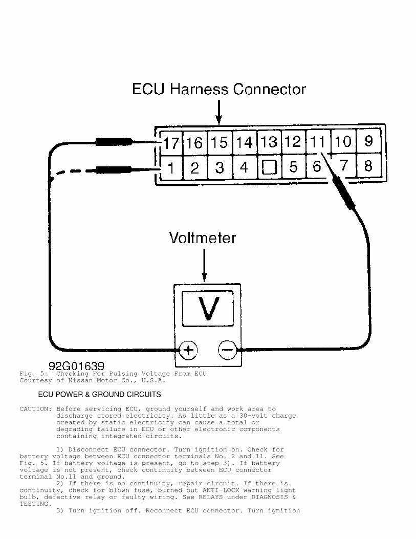
Fig. 5: Checking For Pulsing Voltage From ECUCourtesy of Nissan Motor Co., U.S.A.
ECU POWER & GROUND CIRCUITS
CAUTION: Before servicing ECU, ground yourself and work area to discharge stored electricity. As little as a 30-volt charge created by static electricity can cause a total or degrading failure in ECU or other electronic components containing integrated circuits.
1) Disconnect ECU connector. Turn ignition on. Check forbattery voltage between ECU connector terminals No. 2 and 11. SeeFig. 5. If battery voltage is present, go to step 3). If batteryvoltage is not present, check continuity between ECU connectorterminal No.11 and ground. 2) If there is no continuity, repair circuit. If there iscontinuity, check for blown fuse, burned out ANTI-LOCK warning lightbulb, defective relay or faulty wiring. See RELAYS under DIAGNOSIS &TESTING. 3) Turn ignition off. Reconnect ECU connector. Turn ignition
on. Measure voltage between ECU connector terminals No. 11 and 12. Ifbattery voltage is not present, check fuse, relay and wiring harness.See RELAYS under DIAGNOSIS & TESTING. 4) If battery voltage is present, measure voltage between ECUconnector terminals No. 8 and 11. Battery voltage should be presentwith brake pedal pressed. Battery voltage should not be present withbrake pedal released. 5) If voltage is as specified, go to next step. If voltage isnot as specified, adjust brakelight switch. See BRAKELIGHT & CRUISECONTROL SWITCHES under ADJUSTMENTS. If adjustment is correct, replaceswitch or repair harness. 6) Ensure brake fluid level is correct. Release parkingbrake. Check for battery voltage between ECU connector terminals No. 5and 11. If battery voltage is present, go to next step. If batteryvoltage is not present, adjust parking brake switch. If switchadjustment is correct, replace switch or repair harness and/orconnectors. 7) Set parking brake. Voltage should drop to about zerovolts. If voltage drops as specified, ECU power and ground circuitsare okay. If voltage does not drop, check parking brake switch,harness and/or connectors.
PROPORTIONING VALVE
Pressure Testing Connect pressure gauges to front and rear brake bleeders.Bleed air from hydraulic system. Press brake pedal until frontpressure is as specified. See PROPORTIONING VALVE PRESSURESPECIFICATIONS table. Check rear pressure. If rear pressure is withinspecification, proportioning valve is okay. If rear pressure is notwithin specification, replace master cylinder.
PROPORTIONING VALVE PRESSURE SPECIFICATIONS TABLE�����������������������������������������������������������������������������������������������������������������������Application Front Brake Rear Brake Pressure Pressure psi (kg/cm
�) psi (kg/cm
�)
Pathfinder Rear Disc Brake ...... 995 (69) ....... 711-825 (49-57) Rear Drum Brake ...... 995 (69) ....... 583-697 (40-48)Pickup ................ 995 (69) ....... 327-441 (23-30)�����������������������������������������������������������������������������������������������������������������������
RELAYS
Ignition Relay No. 2 (With Power Windows And/Or Adjustable Shock Absorbers) Remove relay. Check continuity between relay terminals No. 3and 5, and between terminals No. 6 and 7. See Fig. 6. Continuityshould not be present. Apply battery voltage between terminals No. 1and 2. Continuity should be present between terminals No. 3 and 5, andbetween terminals No. 6 and 7. Replace relay if continuity is not asspecified.
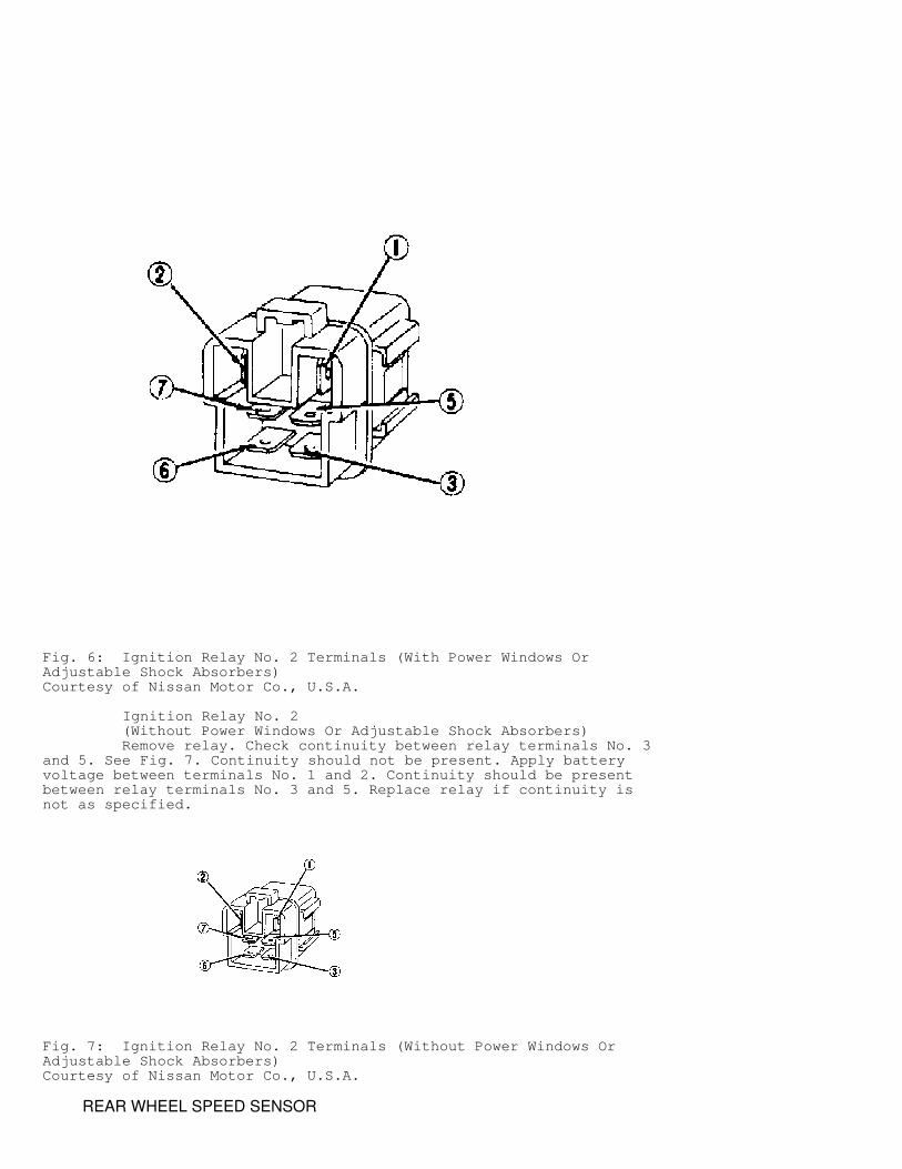
Fig. 6: Ignition Relay No. 2 Terminals (With Power Windows OrAdjustable Shock Absorbers)Courtesy of Nissan Motor Co., U.S.A.
Ignition Relay No. 2 (Without Power Windows Or Adjustable Shock Absorbers) Remove relay. Check continuity between relay terminals No. 3and 5. See Fig. 7. Continuity should not be present. Apply batteryvoltage between terminals No. 1 and 2. Continuity should be presentbetween relay terminals No. 3 and 5. Replace relay if continuity isnot as specified.
Fig. 7: Ignition Relay No. 2 Terminals (Without Power Windows OrAdjustable Shock Absorbers)Courtesy of Nissan Motor Co., U.S.A.
REAR WHEEL SPEED SENSOR
Signal Voltage Test 1) Raise and support rear of vehicle with wheels off ground.Start engine. Shift transmission into Drive (A/T) or 1st gear (M/T).Allow rear wheels to rotate with engine idling at about 830 RPM (A/T)or 620 RPM (M/T). 2) Check AC voltage between ECU connector terminals No. 9 and10. See Fig. 5. If AC voltage is .4 volt or greater, signal voltage isokay. If AC voltage is less than .4 volt, turn engine off. 3) Inspect condition of sensor rotor teeth. Check sensorrotor installation on companion flange. Check rotor for deformation,wear and looseness. If rotor is okay, replace sensor unit. If rotor isdamaged, replace rotor and companion flange as a set. See WHEEL SPEEDSENSOR under REMOVAL & INSTALLATION.
REMOVAL & INSTALLATION
ACTUATOR
Removal & Installation Disconnect negative battery cable. Drain brake fluid.Disconnect electrical connectors and brakelines from actuator. Removeactuator mounting nuts. Remove actuator. To install, reverse removalprocedure. Bleed brake system. See BLEEDING BRAKE SYSTEM.
ELECTRONIC CONTROL UNIT (ECU)
CAUTION: Before servicing ECU, ground yourself and ground the work area to discharge stored electricity. As little as a 30-volt charge created by static electricity can cause a total or degrading failure in ECU or other electronic components containing integrated circuits.
Removal Disconnect negative battery cable. Remove lower center trimfrom instrument panel. Disconnect ECU connector. Remove bolts and ECU.
Installation To install, reverse removal procedure.
WHEEL SPEED SENSOR
Removal & Installation 1) Disconnect negative battery cable. Raise and support rearof vehicle. Disconnect drive shaft from rear differential companionflange. See Fig. 8. 2) Remove companion flange nut and companion flange. DO NOTdamage sensor rotor mounted on companion flange. If rotor is damaged,replace companion flange and rotor as a set. Remove bolts and sensorunit. To install components, reverse removal procedure.
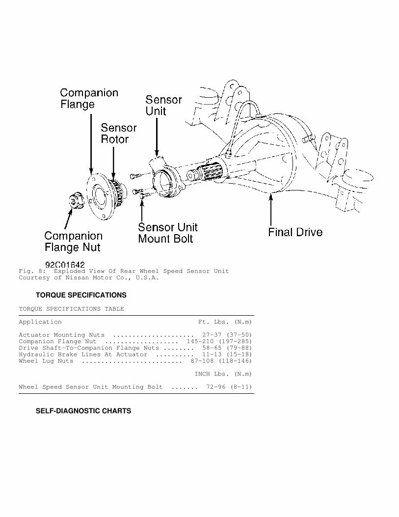
Fig. 8: Exploded View Of Rear Wheel Speed Sensor UnitCourtesy of Nissan Motor Co., U.S.A.
TORQUE SPECIFICATIONS
TORQUE SPECIFICATIONS TABLE�����������������������������������������������������������������������������������������������������������������������Application Ft. Lbs. (N.m)
Actuator Mounting Nuts ..................... 27-37 (37-50)Companion Flange Nut ................... 145-210 (197-285)Drive Shaft-To-Companion Flange Nuts ........ 58-65 (79-88)Hydraulic Brake Lines At Actuator .......... 11-13 (15-18)Wheel Lug Nuts .......................... 87-108 (118-146)
INCH Lbs. (N.m)
Wheel Speed Sensor Unit Mounting Bolt ....... 72-96 (8-11)�����������������������������������������������������������������������������������������������������������������������
SELF-DIAGNOSTIC CHARTS
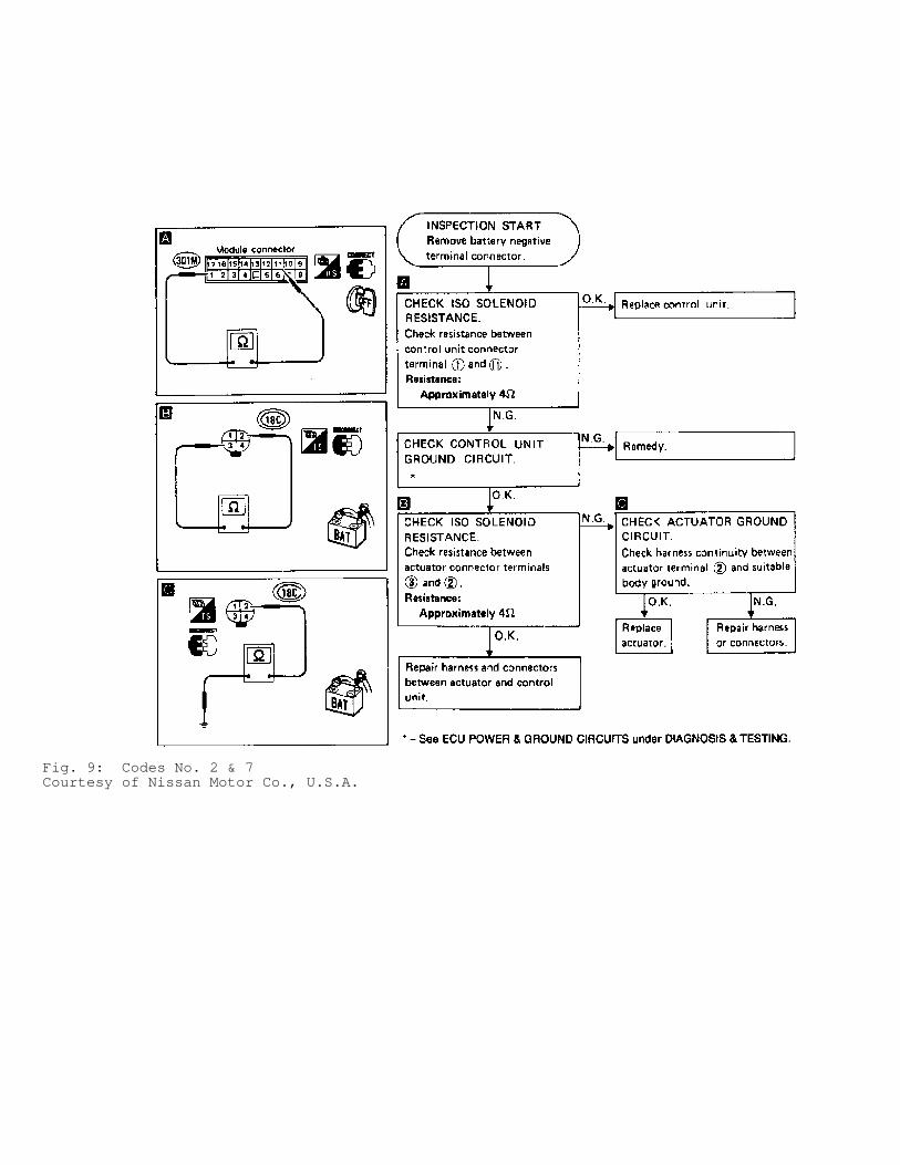
Fig. 9: Codes No. 2 & 7Courtesy of Nissan Motor Co., U.S.A.
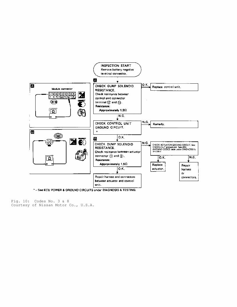
Fig. 10: Codes No. 3 & 8Courtesy of Nissan Motor Co., U.S.A.
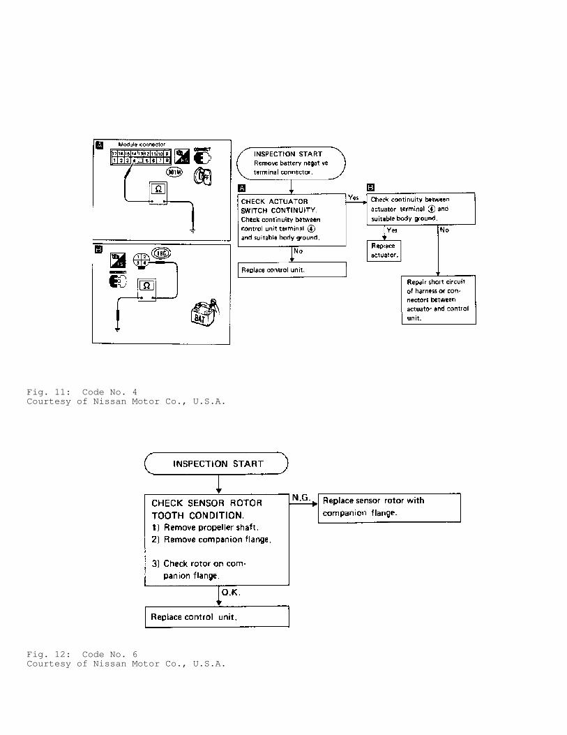
Fig. 11: Code No. 4Courtesy of Nissan Motor Co., U.S.A.
Fig. 12: Code No. 6Courtesy of Nissan Motor Co., U.S.A.

Fig. 13: Codes No. 9 & 10Courtesy of Nissan Motor Co., U.S.A.
WIRING DIAGRAM
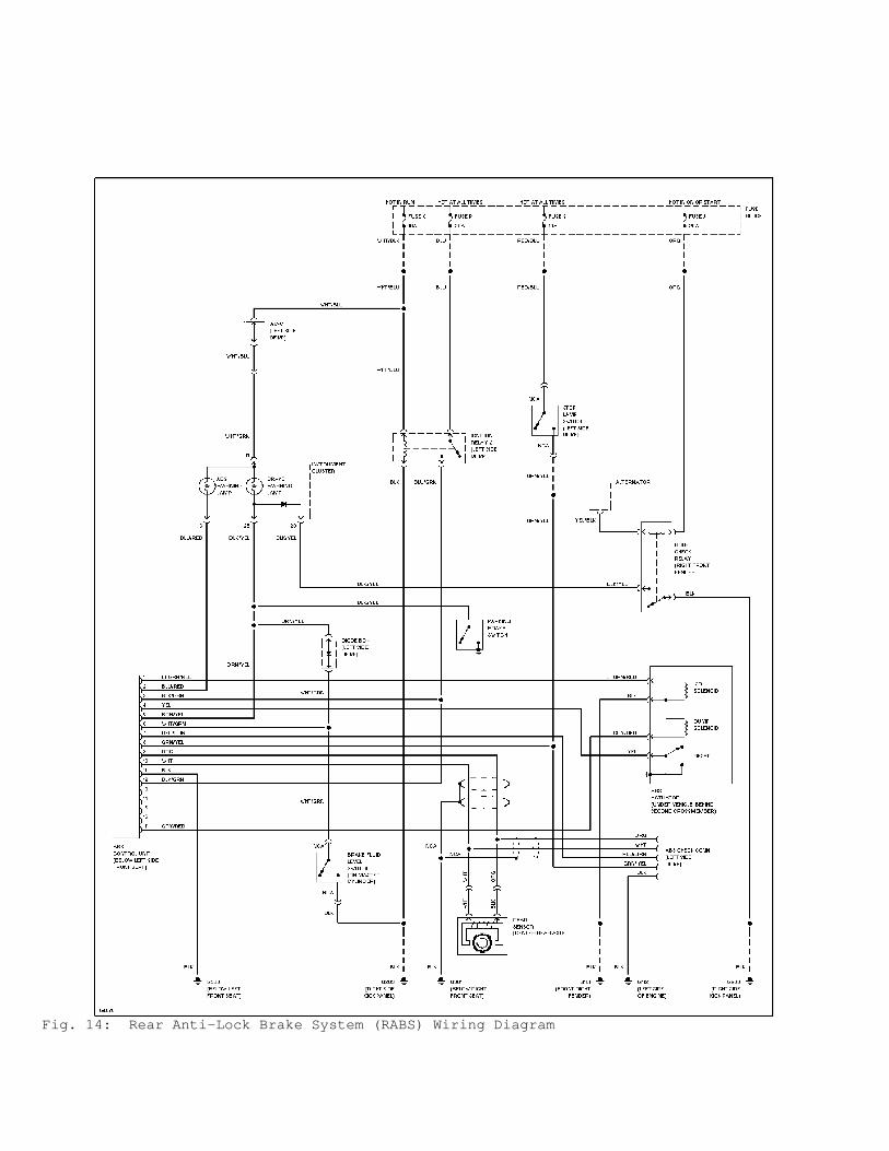
Fig. 14: Rear Anti-Lock Brake System (RABS) Wiring Diagram