Antennas Demystified Scott Honaker N7WLO. Importance of Antennas Antennas are as important as the...
30
Antennas Antennas Demystified Demystified Scott Honaker Scott Honaker N7WLO N7WLO
-
Upload
eustacia-ward -
Category
Documents
-
view
223 -
download
3
Transcript of Antennas Demystified Scott Honaker N7WLO. Importance of Antennas Antennas are as important as the...

Antennas Antennas DemystifiedDemystified
Scott HonakerScott Honaker
N7WLON7WLO

Importance of AntennasImportance of Antennas
Antennas are as important as the Antennas are as important as the radioradio
A $5000 TV with rabbit ears will A $5000 TV with rabbit ears will have a lousy picturehave a lousy picture
Antennas are cheaper than Antennas are cheaper than amplifiersamplifiers
Antennas are Antennas are reciprocalreciprocal – they hear – they hear as well as they talkas well as they talk

Choosing AntennasChoosing Antennas Frequency – Dictates sizeFrequency – Dictates size Mounting location – Base or mobileMounting location – Base or mobile Omni or directional – Coverage or gainOmni or directional – Coverage or gain Polarization – Horizontal, vertical, Polarization – Horizontal, vertical,
circularcircular Resonant or non-resonant – Tuner Resonant or non-resonant – Tuner
required?required? Power availablePower available Feedline length and typeFeedline length and type CostCost

dBi vs. dBddBi vs. dBd
dBi - Gain vs. Isotropic ResonatordBi - Gain vs. Isotropic Resonator Isotropic Resonator is infinitely small Isotropic Resonator is infinitely small
antenna with no feedline in free space antenna with no feedline in free space radiating equally well in all directions radiating equally well in all directions (spherical pattern)(spherical pattern)
dBd - Gain vs. Reference DipoledBd - Gain vs. Reference Dipole Gain referenced to a “real” dipole Gain referenced to a “real” dipole
antenna with a donut-like patternantenna with a donut-like pattern dBd = dBi + 2.15 dBdBd = dBi + 2.15 dB

Gain/Loss CalculationsGain/Loss Calculations
ERP (Effective Radiated Power) is ERP (Effective Radiated Power) is the real number to considerthe real number to consider
Gain uses a Log-10 scaleGain uses a Log-10 scale 3dB = 2-fold improvement3dB = 2-fold improvement 6dB = 4-fold improvement6dB = 4-fold improvement 10dB = 10-fold improvement10dB = 10-fold improvement 20dB = 100-fold improvement20dB = 100-fold improvement
• ERP=Power x (Gain - Feedline Loss)ERP=Power x (Gain - Feedline Loss)

Radiation PatternsRadiation Patterns
Visual representation of gain, Visual representation of gain, beamwidth, F/B ratio and F/S beamwidth, F/B ratio and F/S ratio in one planeratio in one plane
E-Plane is cross-E-Plane is cross-section that includes section that includes driven element driven element
H-Plane is H-Plane is perpendicular to perpendicular to driven elementdriven element

Dipole PatternsDipole Patterns

Yagi PatternsYagi Patterns
E-Plane H-Plane
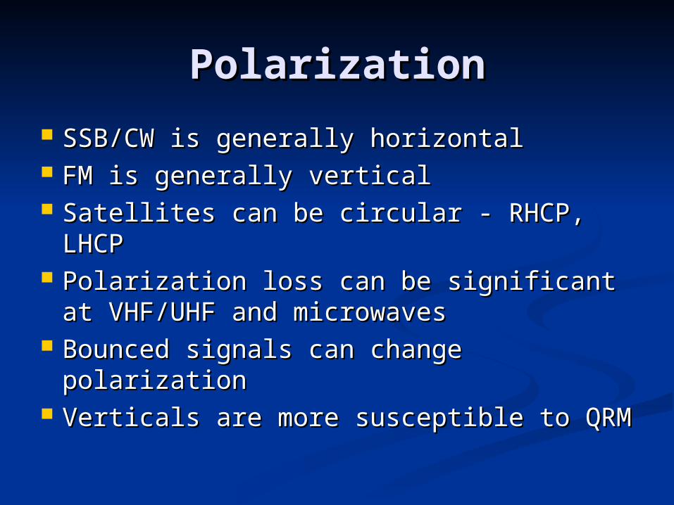
PolarizationPolarization
SSB/CW is generally horizontalSSB/CW is generally horizontal FM is generally verticalFM is generally vertical Satellites can be circular - RHCP, LHCPSatellites can be circular - RHCP, LHCP Polarization loss can be significant at Polarization loss can be significant at
VHF/UHF and microwavesVHF/UHF and microwaves Bounced signals can change polarizationBounced signals can change polarization Verticals are more susceptible to QRMVerticals are more susceptible to QRM

Antenna Design Antenna Design ConsiderationsConsiderations
Gain, SWR, Bandwidth, Front/Back Gain, SWR, Bandwidth, Front/Back ratio are related and optimum values ratio are related and optimum values are not achieved simultaneously for are not achieved simultaneously for eacheach
Does antenna have power going in Does antenna have power going in desired direction? Gain/Beamwidthdesired direction? Gain/Beamwidth

SWR Power LossesSWR Power Losses
All powerAll power fed into the line, minus the fed into the line, minus the line attenuation, is absorbed into the line attenuation, is absorbed into the load (antenna) load (antenna) regardless of the regardless of the mismatch at the antenna terminalsmismatch at the antenna terminals
Line attenuation (loss) is the key Line attenuation (loss) is the key factor in determining losses due to factor in determining losses due to mismatched antennas (high SWR)mismatched antennas (high SWR)

SWR Loss ExamplesSWR Loss Examples
SWR losses are added SWR losses are added to line attenuation for to line attenuation for total loss valuestotal loss values
100’ RG-58 @ 20 100’ RG-58 @ 20 meters, 50’ RG-8x @ 2 meters, 50’ RG-8x @ 2 meters,meters,50’ Belden 9913 @ 50’ Belden 9913 @ 70cm have nearly 70cm have nearly identical attenuation identical attenuation of 1.5dBof 1.5dB
SWSWRR
SWR LossesSWR Losses
1.0:1.0:11
0dB0dB
1.5:1.5:11
0dB0dB
2.0:2.0:11
0.2dB or 5%0.2dB or 5%
3.0:3.0:11
0.6dB or 0.6dB or 13%13%
5.0:5.0:11
1.5dB or 1.5dB or 29%29%
10:110:1 3.0dB or 3.0dB or 50%50%

LoadingLoading
Inductive loads – base, center, topInductive loads – base, center, top Screwdriver antennas (adjustable Screwdriver antennas (adjustable
loading)loading) Hamstick-style antennasHamstick-style antennas Hustler center-loaded Hustler center-loaded
whipswhips Rubber HT antennasRubber HT antennas
Capacitance “Hats”Capacitance “Hats” Texas BugcatcherTexas Bugcatcher Cushcraft MA5BCushcraft MA5B

Ground Plane VerticalsGround Plane Verticals
¼ wave is omnidirectional with unity ¼ wave is omnidirectional with unity (0dBd) gain when provided a proper (0dBd) gain when provided a proper ground planeground plane
½ wave is unity gain with no ground plane ½ wave is unity gain with no ground plane and 3dBd with ground planeand 3dBd with ground plane
5/8 wave is 3.5dBd gain with nice omni 5/8 wave is 3.5dBd gain with nice omni pattern and low radiation anglepattern and low radiation angle
Longer antennas have more omni patterns Longer antennas have more omni patterns with asymmetric ground planes (vehicles) with asymmetric ground planes (vehicles) and lower radiation angles (see below)and lower radiation angles (see below)
¼ wave
½ wave
5/8 wave

Ground PlanesGround Planes
““Perfect” ground plane from 120 evenly Perfect” ground plane from 120 evenly spaced radials at least ½ wave in lengthspaced radials at least ½ wave in length
Wire mesh or wire from #12 to #28, Wire mesh or wire from #12 to #28, above or a few inches below the ground above or a few inches below the ground work finework fine
Elevated feeds (1/8Elevated feeds (1/8λλ or more above or more above ground) can use four ¼-wave radialsground) can use four ¼-wave radials
Vehicles provide poor ground planes at Vehicles provide poor ground planes at HF but elevating the feedpoint reduces HF but elevating the feedpoint reduces lossloss

Imperfect Ground PlanesImperfect Ground Planes
Number of Number of radialsradials
1616 2424 3636 6060 9090 121200
Length of radials Length of radials in wavelengthsin wavelengths
0.10.1 0.120.1255
0.10.155
0.0.22
0.20.255
0.40.4
Total wire Total wire installed in installed in wavelengthswavelengths
1.61.6 33 5.45.4 1212 22.22.55
4848
Power loss Power loss relative to relative to “perfect” ground “perfect” ground planeplane
33 22 1.51.5 11 0.50.5 n/an/a
Feedpoint Feedpoint impedance in impedance in ohmsohms
5252 4646 4343 4040 3737 3535

Other VerticalsOther Verticals DisconeDiscone
Wide usable frequency Wide usable frequency range range
SWR ~2:1 for fundamental SWR ~2:1 for fundamental through second harmonicthrough second harmonic
SWR ~3:1 for remainder of SWR ~3:1 for remainder of coveragecoverage
Omnidirectional – Unity Omnidirectional – Unity gaingain
Inverted-LInverted-L 2-3 dBd gain with vertical 2-3 dBd gain with vertical
and horizontal componentsand horizontal components Requires ground planeRequires ground plane

Balanced Feed DesignsBalanced Feed Designs
DipoleDipole Simple and effectiveSimple and effective Vertical or horizontal polarizationVertical or horizontal polarization
LoopLoop Full wave has 3dBd gainFull wave has 3dBd gain Circular, Quad (square) or Delta Circular, Quad (square) or Delta
(triangular) design(triangular) design E and H-plane patterns vary with E and H-plane patterns vary with
height above groundheight above ground

Dipole TypesDipole Types SloperSloper
Has 3dB to 6dB of Has 3dB to 6dB of directivity toward slopedirectivity toward slope
Inverted-VInverted-V Single high mount, internal Single high mount, internal
angle should be >90 angle should be >90 degreesdegrees
BentBent Good attic antennaGood attic antenna Keep center section straightKeep center section straight Remainder of element can Remainder of element can
bend or curve to fitbend or curve to fit

Dipole Types – Cont.Dipole Types – Cont.
FoldedFolded High impedance needs High impedance needs
open wire feed open wire feed Same overall size as ½ waveSame overall size as ½ wave
dipole but contains 1 wave of wire for nearly 3 dBd dipole but contains 1 wave of wire for nearly 3 dBd gaingain
CagedCaged Standard dipole with each leg made up of multiple Standard dipole with each leg made up of multiple
wires around spacers forming a wire tubewires around spacers forming a wire tube Larger effective element diameter increases Larger effective element diameter increases
bandwidthbandwidth Extended Double ZeppExtended Double Zepp
Two 0.64Two 0.64λλ elements provide 3dBd gain elements provide 3dBd gain

Multiband DipolesMultiband Dipoles
Multiple Multiple Multiple dipoles/loops at a single feedMultiple dipoles/loops at a single feed
Trap Trap Traps are tuned circuits used to generate Traps are tuned circuits used to generate
multiple resonances on a single wiremultiple resonances on a single wire Traps cause loss and decrease bandwidthTraps cause loss and decrease bandwidth
G5RVG5RV Non-resonant – tuner requiredNon-resonant – tuner required Radiation patterns vary with frequencyRadiation patterns vary with frequency
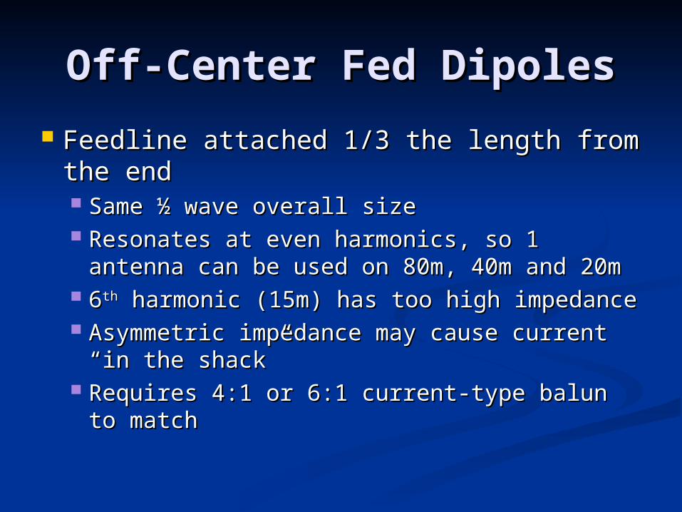
Off-Center Fed DipolesOff-Center Fed Dipoles
Feedline attached 1/3 the length from Feedline attached 1/3 the length from the endthe end Same ½ wave overall sizeSame ½ wave overall size Resonates at even harmonics, so 1 antenna Resonates at even harmonics, so 1 antenna
can be used on 80m, 40m and 20mcan be used on 80m, 40m and 20m 66thth harmonic (15m) has too high impedance harmonic (15m) has too high impedance Asymmetric impedance may cause current Asymmetric impedance may cause current
“in the shack”“in the shack” Requires 4:1 or 6:1 current-type balun to Requires 4:1 or 6:1 current-type balun to
matchmatch

Other MultibandersOther Multibanders
Random wireRandom wire Can be any length of wireCan be any length of wire Requires tunerRequires tuner Works against earth groundWorks against earth ground
WindomWindom ““T” shape single wire feed attached T” shape single wire feed attached
14% off center14% off center Works against earth groundWorks against earth ground ““RF in the shack” is a potential problemRF in the shack” is a potential problem

Wire ArraysWire Arrays
Half SquareHalf Square Vertical polarization with up to 3.8dBd gainVertical polarization with up to 3.8dBd gain
Bi-squareBi-square Horizontal polarization with ~3.5dBd gainHorizontal polarization with ~3.5dBd gain
Bobtail CurtainBobtail Curtain Vertical polarization with bidirectional 5.8 dBd Vertical polarization with bidirectional 5.8 dBd
gaingain Sterba CurtainSterba Curtain
Horizontal polarization from multiple phased loopsHorizontal polarization from multiple phased loops Lazy “H” – Four element broadside arrayLazy “H” – Four element broadside array
Greater than 6dBd gain possibleGreater than 6dBd gain possible

YagisYagis
½ wave dipole driven element½ wave dipole driven element Reflectors are 5% largerReflectors are 5% larger Directors are 5% smallerDirectors are 5% smaller Number of elements and boom Number of elements and boom
length determine gainlength determine gain SWR, bandwidth, gain, boom length SWR, bandwidth, gain, boom length
and front/back ratios all have to be and front/back ratios all have to be consideredconsidered

Typical Yagi GainsTypical Yagi Gains
10m yagi 10m yagi with SWR with SWR <2:1 and <2:1 and Front/Back Front/Back >20dB>20dB Numbers are Numbers are
rounded to rounded to nearest 0.5 nearest 0.5 dBdB
ElemenElementsts
Gain Gain dBidBi
Gain Gain dBddBd
33 7.57.5 5.55.5
44 8.58.5 6.56.5
55 1010 88
66 11.511.5 9.59.5
77 12.512.5 10.510.5
88 13.513.5 11.511.5

Hybrid YagisHybrid Yagis
QuadQuad 11λλ loop driven element, reflector and loop driven element, reflector and
directorsdirectors Up to 3dBd gain over standard yagiUp to 3dBd gain over standard yagi Wider bandwidth than standard yagiWider bandwidth than standard yagi
QuagiQuagi Loop reflector and driven elementLoop reflector and driven element Simpler to feed and match at UHFSimpler to feed and match at UHF
LooperLooper Entirely loop (generally circular) elementsEntirely loop (generally circular) elements

Log PeriodicLog Periodic Constant characteristics Constant characteristics
over wide band (2:1)over wide band (2:1) Several varieties but Several varieties but
hams generally use hams generally use dipole array (LPDA)dipole array (LPDA)
All elements are drivenAll elements are driven Gain similar to 3 Gain similar to 3
elementelement yagi – 7dBi, 5dBd yagi – 7dBi, 5dBd
Size similar to 3 elementSize similar to 3 element yagi at lowest frequency yagi at lowest frequency

Reflecting AntennasReflecting Antennas Corner reflectorCorner reflector
Practical size at 222 MHz and upPractical size at 222 MHz and up Simple to construct, broadbanded, gains 10-Simple to construct, broadbanded, gains 10-
15dBd15dBd Pyramidal HornPyramidal Horn
Practical at 902 MHz and upPractical at 902 MHz and up Sides of horn are fed for up to 15 dBi, Sides of horn are fed for up to 15 dBi,
13dBd gain13dBd gain Parabolic dishParabolic dish
Gain is a function of reflector diameter, Gain is a function of reflector diameter, surface accuracy and illuminationsurface accuracy and illumination

Parabolic Dish GainParabolic Dish Gain
MHzMHz 2’2’ 4’4’ 6’6’ 10’10’ 20’20’ 30’30’
420420 6.0d6.0dBiBi
12.012.0 15.515.5 20.020.0 26.026.0 29.529.5
902902 12.512.5 18.518.5 22.022.0 26.526.5 32.532.5 36.036.0
12151215 15.015.0 21.021.0 24.524.5 29.029.0 35.035.0 38.538.5
23002300 20.520.5 26.526.5 30.030.0 34.534.5 40.540.5 44.044.0
33003300 24.024.0 30.030.0 33.533.5 37.537.5 41.541.5 47.547.5
56505650 28.528.5 34.534.5 38.038.0 42.542.5 46.046.0 52.052.0
10Gh10Ghzz
33.533.5 39.539.5 43.043.0 47.547.5 51.051.0 57.057.0