
AntennaBeamBroadeninginMultifunction...
6
Vol. 119 (2011) ACTA PHYSICA POLONICA A No. 4 Physical Aspects of Microwave and Radar Applications Antenna Beam Broadening in Multifunction Phased Array Radar R. Fatemi Mofrad * and R.A. Sadeghzadeh Electrical & Computer Engineering Department, K.N. Toosi University of Technology, Tehran, Iran A phased array antenna is designed for multifunction phased array radar simulation test bed. Effect of element pattern, mutual coupling between elements, phase quantization, amplitude and phase error and elements failure rates on array pattern are discussed. Target angle measurement and side lobe cancelling, in order to reduce jamming power through side lobes, is illustrated in this antenna. Also antenna beam width is broadened with different methods and compared with narrow beam characteristics. It is shown that, for special broad- ening factors, beam broadening may lead to a better coverage and power efficiency relative to narrow beam antenna. PACS: 84.40.Ba, 84.40.Xb, 84.40.Ua 1. Introduction Phased array antennas have matured rapidly in recent years and this technology is set to become the norm in complex and advanced radar systems. The ability to steer the radar beam electronically allows a combination of functions, such as tracking, surveillance and weapon guidance, which were traditionally performed by dedi- cated individual radars. This new type of radar is called multifunction array radar (MFAR). In these radars, ef- fect of different antenna beam characteristics (e.g. beam width) or tracking algorithms on the overall radar per- formance need to be done based on realistic simulations, because these sophisticated radars cannot be tested com- pletely in real world. These realistic simulations should have two main properties: first to include different as- pects of real operational scenarios facing MFAR as much and accurate as possible. The second is that these sim- ulations should provide the facility to model different part of a MFAR in order to evaluate the performance of each section in the radar as a whole system (to con- sider the interaction between subsystems). MFAR simu- lation test bed is a software tool for MFAR designers to design and evaluate the performance of such kind of so- phisticated radars [1]. In the MFAR simulation test bed, active phased array radar, with specification in Table I, is considered as a pilot for different radar resource man- agement, target tracking and beam forming algorithms comparison and development. In this simulation test bed, transmitting and receiving chain, antenna structure and signal processing algorithms are fixed. User may write his or her own radar resource management, target tracking and beam forming algorithms and after defining appro- priate operational scenarios, assess results of the designed algorithms. The most important part of this simulation test bed is a phased array antenna. That is an active * corresponding author; e-mail: [email protected] phased array with about 5000 elements. It is assumed that digital beam forming is possible at element level and so designer may design appropriate beam forming algo- rithms and evaluate the results on radar performances. TABLE I MFAR characteristics. MFAR parameter Value angle tracking accuracy 12 0 antenna scanning range in az. and el. -45 ◦ – +45 ◦ antenna tilt angle 0–45 ◦ frequency band S antenna beamwidth 1.5 ◦ × 1.7 ◦ polarization vertical antenna gain 40 dB sum pattern side lobe level 30 dB difference pattern side lobe level 20 dB number of T/R modules 5000 In this paper, a narrow pencil beam with capability to measure azimuth and elevation angles of target and side lobe cancelling in the presence of jamming is designed for this simulation test bed. Effect of element pattern, phase quantization, amplitude and phase error, elements failure rates on array pattern and mutual coupling be- tween elements, are presented. The narrow beam width is usually designed to meet tracking requirements of a MFAR (resolution and accuracy). Search of a large area by this narrow beam becomes too time consuming. In these occasions antenna beam broadening is useful. In this paper antenna beam width is broadened and compared with narrow beam characteristics. It is shown that, for special broadening factors, beam broadening may lead to a better coverage and power efficiency rela- tive to narrow beam antenna. (461)
Transcript of AntennaBeamBroadeninginMultifunction...
Vol. 119 (2011) ACTA PHYSICA POLONICA A No. 4
Physical Aspects of Microwave and Radar Applications
Antenna Beam Broadening in MultifunctionPhased Array Radar
R. Fatemi Mofrad∗ and R.A. SadeghzadehElectrical & Computer Engineering Department, K.N. Toosi University of Technology, Tehran, Iran
A phased array antenna is designed for multifunction phased array radar simulation test bed. Effect ofelement pattern, mutual coupling between elements, phase quantization, amplitude and phase error and elementsfailure rates on array pattern are discussed. Target angle measurement and side lobe cancelling, in order toreduce jamming power through side lobes, is illustrated in this antenna. Also antenna beam width is broadenedwith different methods and compared with narrow beam characteristics. It is shown that, for special broad-ening factors, beam broadening may lead to a better coverage and power efficiency relative to narrow beam antenna.
PACS: 84.40.Ba, 84.40.Xb, 84.40.Ua
1. Introduction
Phased array antennas have matured rapidly in recentyears and this technology is set to become the norm incomplex and advanced radar systems. The ability tosteer the radar beam electronically allows a combinationof functions, such as tracking, surveillance and weaponguidance, which were traditionally performed by dedi-cated individual radars. This new type of radar is calledmultifunction array radar (MFAR). In these radars, ef-fect of different antenna beam characteristics (e.g. beamwidth) or tracking algorithms on the overall radar per-formance need to be done based on realistic simulations,because these sophisticated radars cannot be tested com-pletely in real world. These realistic simulations shouldhave two main properties: first to include different as-pects of real operational scenarios facing MFAR as muchand accurate as possible. The second is that these sim-ulations should provide the facility to model differentpart of a MFAR in order to evaluate the performanceof each section in the radar as a whole system (to con-sider the interaction between subsystems). MFAR simu-lation test bed is a software tool for MFAR designers todesign and evaluate the performance of such kind of so-phisticated radars [1]. In the MFAR simulation test bed,active phased array radar, with specification in Table I,is considered as a pilot for different radar resource man-agement, target tracking and beam forming algorithmscomparison and development. In this simulation test bed,transmitting and receiving chain, antenna structure andsignal processing algorithms are fixed. User may write hisor her own radar resource management, target trackingand beam forming algorithms and after defining appro-priate operational scenarios, assess results of the designedalgorithms. The most important part of this simulationtest bed is a phased array antenna. That is an active
∗ corresponding author; e-mail: [email protected]
phased array with about 5000 elements. It is assumedthat digital beam forming is possible at element level andso designer may design appropriate beam forming algo-rithms and evaluate the results on radar performances.
TABLE IMFAR characteristics.
MFAR parameter Valueangle tracking accuracy 12′
antenna scanning range in az. and el. −45◦– +45◦
antenna tilt angle 0–45◦
frequency band Santenna beamwidth 1.5◦× 1.7◦
polarization verticalantenna gain 40 dB
sum pattern side lobe level 30 dBdifference pattern side lobe level 20 dB
number of T/R modules 5000
In this paper, a narrow pencil beam with capability tomeasure azimuth and elevation angles of target and sidelobe cancelling in the presence of jamming is designedfor this simulation test bed. Effect of element pattern,phase quantization, amplitude and phase error, elementsfailure rates on array pattern and mutual coupling be-tween elements, are presented. The narrow beam widthis usually designed to meet tracking requirements of aMFAR (resolution and accuracy). Search of a large areaby this narrow beam becomes too time consuming. Inthese occasions antenna beam broadening is useful.
In this paper antenna beam width is broadened andcompared with narrow beam characteristics. It is shownthat, for special broadening factors, beam broadeningmay lead to a better coverage and power efficiency rela-tive to narrow beam antenna.
(461)

462 R. Fatemi Mofrad, R.A. Sadeghzadeh
2. Planar array structure
For scanning in elevation and azimuth planar arrayshould be used. Details of planar array theory are givenin available texts [2–4]. All the antenna elements have acertain element pattern e(θ, ϕ). This is multiplied withthe array factor resulting in the final antenna patternE(θ, ϕ) (field strength):
E(θ, ϕ) = e(θ, ϕ)f(θ, ϕ) . (1)
Array antennas often use rectangular or triangularplacement of elements. Usually an array with a trian-gular grating, particularly an equiangular one, is pre-ferred. This arrangement reduces the number of elementsby nearly 13% and increases the area associated to eachelement [5]. Designed array has a rectangular aperturewith 80 elements in azimuth and 64 elements in elevationdirection, so an asymmetrical pattern in H and E planesis produced.
The maximum distance between radiators of a scan-ning antenna array is related to the maximum angle ofdeviation of the pattern. For ±45◦ electronic steering,distance between elements is designed to be equal to0.58λ which will not generate grating lobes. With this se-lection, dimension of aperture will be: 4.64 m × 3.71 m.There are many weighting window types with differentproperties. In the Taylor tapering there is a better trade-off between decrease in the side lobe level and broadeningthe main beam [3]. Amplitude weighting, at T/R modulelevel leads to more complication of the modules (control-lable attenuators and phase shifters will be needed).
Fig. 1. Array pattern with and without Taylor taper-ing.
For difference pattern generation, the aperture can bederived with the Bayliss tapering [3]. The Bayliss ta-pering is applied at output of 160 sub-arrays each with4 × 8 elements [6]. The Bayliss amplitude tapering atsub-array level will increase side lobe level of differencepattern relative to sum pattern. Usually target detectionand acquisition is performed by sum pattern, so higherside lobe level in the difference pattern would not causefalse alarm due to clutter or other unwanted targets.
The radiated pattern of antenna array with and with-out amplitude tapering is shown in Fig. 1. With taper-ing, side lobe level will decrease by about 16 dB. In thetransmission mode the aperture of antenna array shouldoperate with uniform amplitude illumination. In this waymaximum possible power of transmitter modules will bederived with maximum efficiency.
3. Angle measurement
In this antenna, monopulse likelihood function is usedfor direction estimation of target [2]. In likelihood es-timation there is a tapering to form difference pattern.This tapering equals to the coordinates of element whichare distributed symmetrically around axis. This taperingin comparison to the Bayliss tapering produces sharperdifference pattern and increases accuracy of angle estima-tion but with higher side lobes. By multiplying Baylisstapering with this tapering, sharpness of difference pat-tern will decrease but lower side lobes will be produced.The characteristics of this mixed tapering are a tradeoffbetween selection of the Bayliss and likelihood estimationtapering. An example of direction estimation is shown inFig. 2 for beam direction at 35◦ in azimuth and elevation.Figure 3 depicts standard deviation of target direction es-
Fig. 2. Direction estimation for beam direction at 35◦(SNR = 10).
Fig. 3. Standard deviation of target direction estima-tion (in degree) as a function of signal to noise ratio(SNR) (in dB).

Antenna Beam Broadening in Multifunction Phased Array Radar 463
timation as a function of SNR. These results well matchwith similar results in [2].
4. Digital phase shifter
Usually digital phase shifters, characterized by thenumber of bits M , are used for beam steering. M de-
Fig. 4. Increase of side lobe level ratio (SLLR) (in dB)versus scan angle (in degree) with discrete phase shifter.
termines the residual phase error within the interval:∆ϕ = ±π/2M . The main effect of discrete phase shift-ing is on side lobes. In Fig. 4 simulation results showincrease in side lobe level (SLL) with 4 type of discretephase shifters. These results well match with those in [2].According to these results, 6 bits phase shifter has satis-factory results.
5. Element pattern effect
Parameter of the designed microstrip patch antennaat 3 GHz are [6, 7]:
εr = 2.1 ,
L = W = 0.39λ0 ,
d = 0.06λ0 . (2)
In Eq. (2), d is height of substrate, εr is dielectric con-stant of substrate and L and W are dimensions of patch.Half power beam width of element is 80 degree, so there is3 dB loss of effective radiated power (sum of gain and ra-diated power) at ±40 degrees steering angles. The effectof element pattern loss together with beam broadeningloss due to beam steering is depicted in Fig. 5. This resultwell matches with those in [8].
6. 20% failure rate of elements
When 20% of elements accidentally turn off, side lobelevel will increase. Figure 6 compares array pattern inthis condition with main array pattern. Simulation re-sults show that in the worse condition there is 22 dBincrease in side lobe level of sum pattern and 14 dB indifference. The effect of failure on the gain and beamdirection is negligible.
Fig. 5. Decrease of effective radiated power (ERP)(in dB) with scan angle (in degree) because of both el-ement pattern and beam broadening in E-plane.
Fig. 6. Array pattern (in dB) versus scan angle (in de-gree) for 20% failure of elements (160 subarray).
7. Amplitude and phase error
Simulation results show that with 40% amplitude tol-erance there is 2 dB increase in side lobe level. Thiserror is independent of steering angle. Also it has beenshown that destructive effect of phase error is more thanamplitude error. Its main effects are loss in the effectiveradiated power and increase in side lobe level. Accordingto simulation results, maximum tolerable phase error isabout 0.5 ≈ 0.25 rad.
Fig. 7. Decrease of ERP (in dB) with increase of phasetolerance.

464 R. Fatemi Mofrad, R.A. Sadeghzadeh
Fig. 8. Increase in main beam ripples (in dB) versusscan angle (in degree) with increase of phase tolerance.
Figure 7 shows loss of maximum effective power withincrease in phase error. Phase error causes ripples inmain beam and with increasing in phase error these rip-ples may be seen clearly.
This effect is shown in Fig. 8. In this figure decreaseof effective radiated power is also shown. This powerdistributes in side lobes. Side lobes that are far frombore side are higher in comparison with pattern that hasno phase error.
8. Side lobe canceller
The Widrow–Hoff least mean square (LMS), side lobecanceller (SLC) algorithm, which is a closed loop digi-tal algorithm described by [2, 9] was implemented in thesimulation test bed. The benefit of using the SLC can bemeasured by jammer cancellation ratio (CR), defined asthe ratio of the output noise power with and without theSLC. For instance the CR value obtained in this simula-tion test bed with one channel SLC is about 30 dB for ajammer at 14.5◦ azimuth angle.
Fig. 9. Adopted pattern (dotted line) and main pat-tern (continuous line) with one auxiliary antenna forjammer incoming at 14.5◦ azimuth.
Figure 9 shows adapted antenna pattern obtained bythis LMS algorithm. The gain margin of auxiliary SLC
antenna with respect to the side lobe gain of the radarantenna in the jammer direction is an important param-eter. A large value of the gain margin in the steady-stateof an adaptive SLC would be desirable. However, in thetransient state of the SLC a low value of gain marginwould be advisable. A compromise value is around 10 dBfor the gain margin. In Fig. 9 half power beam width ofauxiliary antenna cover ±15◦ around bore sight and soits gain will be 16 dB that is 6 dB more than side lobelevel.
9. Mutual coupling effect
Microstrip patch is a main candidate to be used asthe elements of integrated phased arrays. Such arraysmay include active devices on the same or on a parallelsubstrate, integrated monolithically or in a hybrid fash-ion. Design of these arrays depends on understanding ofthe effects of substrate thickness, dielectric constant, andgrid spacing on the scan performance of the beam. Thescan performance means the active reflection coefficientmagnitude, with the array matched at broadside and isdirectly related to the active element pattern. For an ar-ray of printed patch antenna, scan blindness is possiblewhenever the wave number coincides with the propaga-tion constant of a surface wave on the structure. Scanblindness will occur if the following three conditions aresatisfied [10]:
1) The propagation constant equals surface wave prop-agation constant.
2) The grid spacings dx, dy are such that the equalityof propagation constant in (1) occurs for values of u, vin real space.
3) The pole of TM (TE) surface wave in (1) is notcancelled by a zero value of kx (ky).
Mathematically, condition (1) can be expressed as(
βSW
k0
)2
=(
kx
k0
)2
+(
ky
k0
)2
=(
m
dx/λ0+ sin θ0 cosϕ0
)2
+(
n
dy/λ0+ sin θ0 sin ϕ0
)2
. (3)
In Eq. (3) λ0 is the free space wavelength. Physically,the cancellation condition referred to in (3) means thatthe polarization of the array is such that the particularTM or TE surface wave cannot be excited.
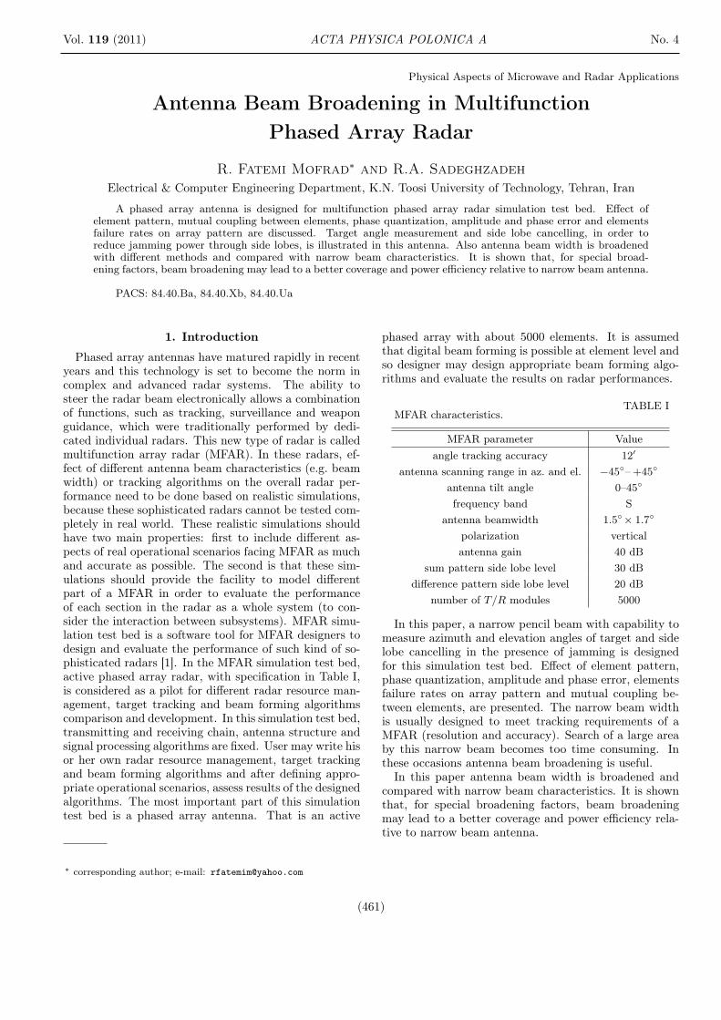
Figure 10 shows blind point versus space between el-ements of designed arrays (with patch length and widthL = W = 0.39λ0, substrate thickness d = 0.06λ0, andsubstrate permittivity εr = 2.1). The blind spot po-sition moves toward broadside by increase in the spacebetween elements. With dx = dy = 0.58λ, the arrayhas a scan blindness in the E-plane at 44.76◦. Withdx = dy = 0.51λ blind spot moves to 70◦ that is a better
Antenna Beam Broadening in Multifunction Phased Array Radar 465
Fig. 10. Blind angle (in degree) versus space betweenelements.
Fig. 11. Reflection coefficient versus scan angle dx =0.51λ, dy = 0.51.
choice for an array with ±45◦ scanning angle. In thiscase the magnitude of the reflection coefficient at 45◦ isabout 0.3 and then the loss of power gain will be only0.4 dB.
Figure 11 shows the magnitude of the reflection coef-ficient of a patch in designed array with spacings dx =dy = 0.5λ. These results well match with those in [3].
10. Beam broadening
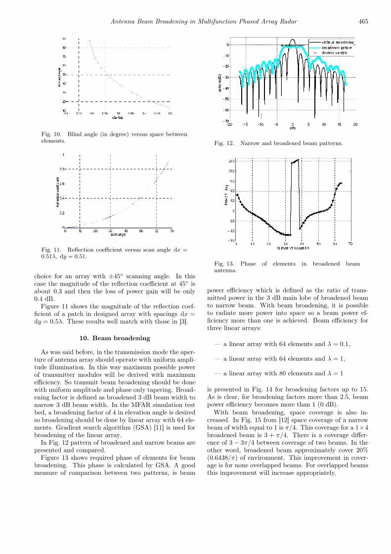
As was said before, in the transmission mode the aper-ture of antenna array should operate with uniform ampli-tude illumination. In this way maximum possible powerof transmitter modules will be derived with maximumefficiency. So transmit beam broadening should be donewith uniform amplitude and phase only tapering. Broad-ening factor is defined as broadened 3 dB beam width tonarrow 3 dB beam width. In the MFAR simulation testbed, a broadening factor of 4 in elevation angle is desiredso broadening should be done by linear array with 64 ele-ments. Gradient search algorithm (GSA) [11] is used forbroadening of the linear array.
In Fig. 12 pattern of broadened and narrow beams arepresented and compared.
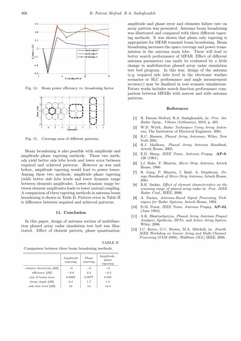
Figure 13 shows required phase of elements for beambroadening. This phase is calculated by GSA. A goodmeasure of comparison between two patterns, is beam
Fig. 12. Narrow and broadened beam patterns.
Fig. 13. Phase of elements in broadened beamantenna.
power efficiency which is defined as the ratio of trans-mitted power in the 3 dB main lobe of broadened beamto narrow beam. With beam broadening, it is possibleto radiate more power into space so a beam power ef-ficiency more than one is achieved. Beam efficiency forthree linear arrays:
— a linear array with 64 elements and λ = 0.1,
— a linear array with 64 elements and λ = 1,
— a linear array with 80 elements and λ = 1
is presented in Fig. 14 for broadening factors up to 15.As is clear, for broadening factors more than 2.5, beampower efficiency becomes more than 1 (0 dB).
With beam broadening, space coverage is also in-creased. In Fig. 15 from [12] space coverage of a narrowbeam of width equal to 1 is π/4. This coverage for a 1×4broadened beam is 3 + π/4. There is a coverage differ-ence of 3− 3π/4 between coverage of two beams. In theother word, broadened beam approximately cover 20%(0.6438/π) of environment. This improvement in cover-age is for none overlapped beams. For overlapped beamsthis improvement will increase appropriately.
466 R. Fatemi Mofrad, R.A. Sadeghzadeh
Fig. 14. Beam power efficiency vs. broadening factor.
Fig. 15. Coverage area of different patterns.
Beam broadening is also possible with amplitude andamplitude–phase tapering methods. These two meth-ods yield better side lobe levels and lower error betweenrequired and achieved patterns. However as was saidbefore, amplitude tapering would lead to power losses.Among these two methods, amplitude–phase taperingyields better side lobe levels and lower dynamic rangebetween elements amplitudes. Lower dynamic range be-tween element amplitudes leads to lower mutual coupling.A comparison of three tapering methods in antenna beambroadening is shown in Table II. Pattern error in Table IIis difference between required and achieved patterns.
11. Conclusion
In this paper, design of antenna section of multifunc-tion phased array radar simulation test bed was illus-trated. Effect of element pattern, phase quantization,
TABLE IIComparison between three beam broadening methods.
Amplitudetapering
Phasetapering
Amplitude–phase
tapering
relative directivity [dB] −6 −6 −6efficiency [dB] −8.8 0.3 −0.3
rms of beam error 0.0889 0.0977 0.095
beam ripple [dB] 0.4 1.7 1.4
side lobe level [dB] 16 13 14.4
amplitude and phase error and elements failure rate onarray pattern was presented. Antenna beam broadeningwas illustrated and compared with three different taper-ing methods. It was shown that phase only tapering isappropriate for MFAR transmit beam broadening. Beambroadening increases the space coverage and power trans-mission in the antenna main lobe. These will lead tobetter search performance of MFAR. Effect of differentantenna parameters can easily be evaluated by a littlechange in multifunction phased array radar simulationtest bed program. In this way, design of the antenna(e.g. required side lobe level in the electronic warfarescenarios or SLC performance and angle measurementaccuracy) may be finalized in real scenario simulations.Future works includes search function performance com-parison between MFARs with narrow and wide antennapatterns.
References
[1] R. Fatemi Mofrad, R.A. Sadeghzadeh, in: Proc. Int.Radar Symp., Vilnius (Lithuania), 2010, p. 265.
[2] W.D. Wirth, Radar Techniques Using Array Anten-nas, The Institution of Electrical Engineers, 2001.
[3] R.C. Hansen, Phased Array Antennas, Wiley, NewYork 2001.
[4] R.J. Mailloux, Phased Array Antenna Handbook,Artech House, 2005.
[5] E.D. Sharp, IEEE Trans. Antenna Propag. AP-9,126 (1961).
[6] I.J. Bahe, P. Bhartia, Micro Strip Antenna, ArtechHouse, 1980.
[7] R. Garg, P. Bhartia, I. Bahl, A. Ittipiboon, De-sign Handbook of Micro Strip Antenna, Artech House,2001.
[8] B.K. Sarkar, Effect of element characteristics on thescanning range of phased array radar in: Proc. IEEERadar Conf., IEEE, 2006.
[9] A. Farina, Antenna-Based Signal Processing Tech-niques for Radar Systems, Artech House, 1994.
[10] D.M. Pozar, IEEE Trans. Antenna Propag. AP-32,(June 1984).
[11] A.K. Bhattacharyya, Phased Array Antenna FloquetAnalysis, Synthesis, BFNs, and Active Array System,Wiley, 2006.
[12] J.C. Kerce, G.C. Brown, M.A. Mitchell, in: FourthIEEE Workshop on Sensor Array and Multi-ChannelProcessing (SAM-2006), Waltham (MA), IEEE, 2006.