Antenna Theory...Wire antenna (half wave dipole) /2 Transmission line Total length of the radiating...
103
Antenna Theory Introduction 1 Transmission line Current distributions Antenna Antennas are device that designed to radiate electromagnetic energy efficiently in a prescribed manner. It is the current distributions on the antennas that produce the radiation. Usually this current distributions are excited by transmission lines and waveguides.
Transcript of Antenna Theory...Wire antenna (half wave dipole) /2 Transmission line Total length of the radiating...

Antenna Theory
Introduction 1
Transmission line Current distributions
Antenna
Antennas are device that designed to radiate electromagnetic energy efficiently in a prescribed manner. It is the current distributions on the antennas that produce the radiation. Usually this current distributions are excited by transmission lines and waveguides.

2
Propagation mode adapter During both transmission and receive operations the antenna must provide the transition between these two propagation modes.

Transmitting Antenna Equivalent Circuit
• Vg - voltage-source generator (transmitter);
• Zg - impedance of the generator (transmitter);
• Rrad - radiation resistance, represents energy radiated into space (related to the radiated power as)
Prad= I2A⋅Rrad
• RL - loss resistance, (related to conduction and dielectric losses); i.e. transformed into heat in the antenna structure
• jX A – antenna reactance.
• ZA=Antenna impedance:
ZA=Rrad+RL+jXA
Transmitter Transm. line
Antenna
Radio wave
Transmission-line Thevenin equivalent circuit of a radiating
(transmitting) system. The antenna is represented by its
input impedance (which is frequency-dependent and is
influenced by objects nearby) as seen from the
generator

Receiving Antenna Equivalent Circuit
Radio wave Receiver Transm.line
Antenna
Transmission-line Thevenin equivalent circuit of a receiving antenna system. Note: The antenna impedance is the same when the antenna is used to radiate and when it is used to receive energy

Freq
uen
cies
& W
avel
engt
hs
After Kraus & Marhefka, 2003

RF Bands, Names & Users
After Kraus & Marhefka, 2003

7
Theory Antennas include wire and aperture types.
Wire types include dipoles, monopoles, loops, rods, stubs, helicies, Yagi-Udas, spirals.
Aperture types include horns, reflectors, parabolic, lenses.

8
Theory In wire-type antennas the radiation characteristics are determined by the current distribution which produces the local magnetic field.
Helical antenna
Yagi-Uda antenna
9
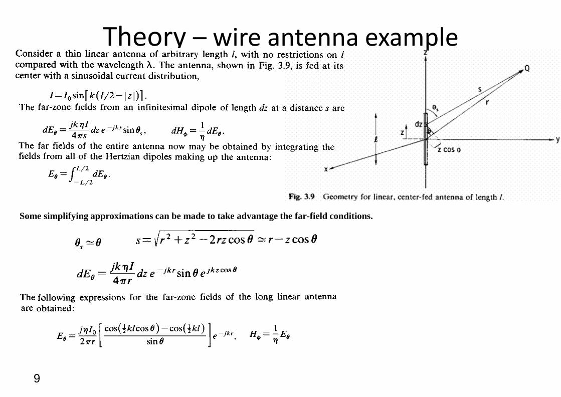
Theory – wire antenna example
Some simplifying approximations can be made to take advantage the far-field conditions.

10
Theory – wire antenna example Once Eq and Ef are known, the radiation characteristics can be determined.
Defining the directional function f (q, f) from
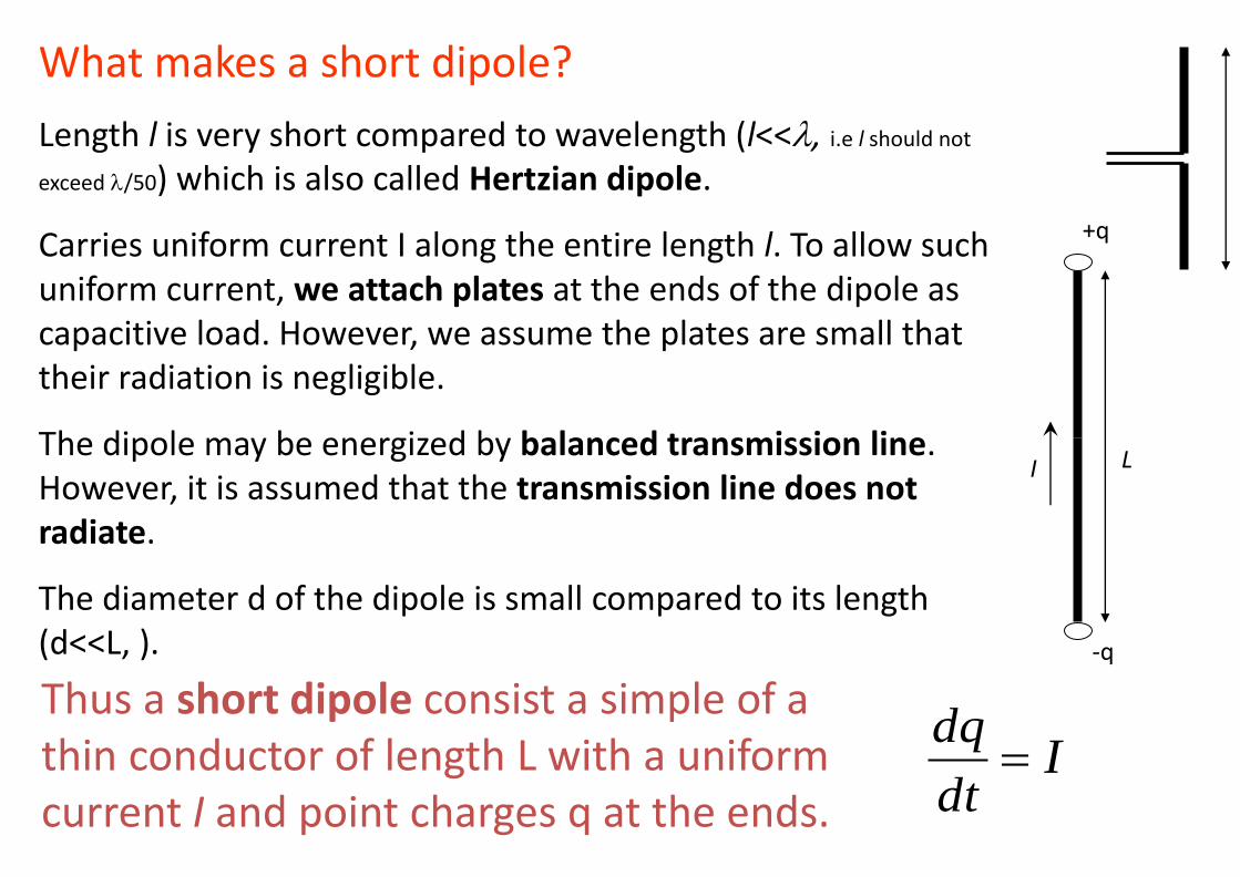
What makes a short dipole?
Length l is very short compared to wavelength (l<<, i.e l should not
exceed /50) which is also called Hertzian dipole.
Carries uniform current I along the entire length l. To allow such uniform current, we attach plates at the ends of the dipole as capacitive load. However, we assume the plates are small that their radiation is negligible.
The dipole may be energized by balanced transmission line. However, it is assumed that the transmission line does not radiate.
The diameter d of the dipole is small compared to its length (d<<L, ).
+q
-q
I L
Thus a short dipole consist a simple of a thin conductor of length L with a uniform current I and point charges q at the ends.
Idt
dq
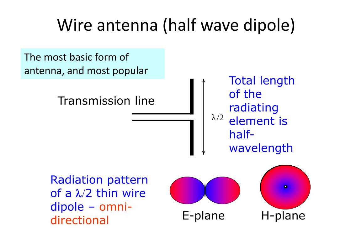
Wire antenna (half wave dipole)
/2
Transmission line
Total length of the radiating element is half-wavelength
E-plane H-plane
Radiation pattern of a 2 thin wire dipole – omni-directional
The most basic form of antenna, and most popular

Quarter wave monopole
1. A quarter-wave monopole antenna excited by a source at its base exhibits the same radiation pattern in the region above the ground plane as a half-wave dipole in free space
2. Use image theory for analysis
3. Hence, a monopole radiates only half as much power as the dipole.
14
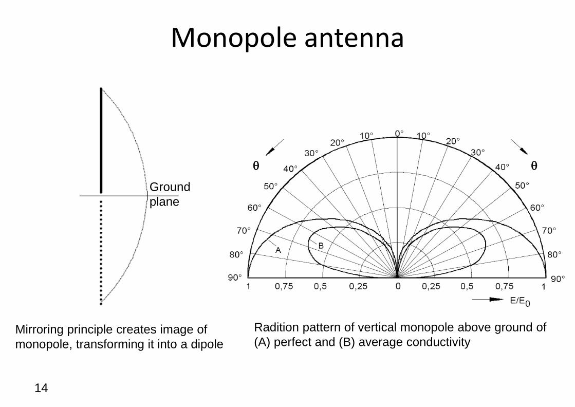
Monopole antenna
Ground
plane
Mirroring principle creates image of
monopole, transforming it into a dipole
Radition pattern of vertical monopole above ground of
(A) perfect and (B) average conductivity
q q

15
Ground plane A ground plane will produce an image of nearby currents. The image will have a phase shift of 180° with respect to the original current. Therefore as the current element is placed close to the surface, the induced image current will effectively cancel the radiating fields from the current.
The ground plane may be any conducting surface including a metal sheet, a water surface, or the ground (soil, pavement, rock).
Horizontal current
element
Current element
image
Conducting surface
(ground plane)

Dipole of other lengths

Field regions
Radiating near field (Fresnel) region
Reactive near field region
Far field (Fraunhofer) region
antenna
No abrupt changes in the field configurations are noted as the boundaries are crossed – but there are distinct differences between the fields


Energy is transferred to and from the near field region which represents the reactive part of the antenna driving point impedance.
As one moves further away, this oscillatory energy flow reduces leaving just the regular power flow in the resistive characteristic impedance (377 ohms or 120 pi ohms) of free space.
In the far field the polar radiation pattern is completely independent of distance from the radiating source.


Reactive near field region
362.0 DR 2/
24
sin
r
eLIH
rj
m
q
f
3
3
4
)sin(
2
)cos(
rj
eLI
rj
eLI
r
jm
jm
E
E
q
q
q
“That portion of the near field region immediately surrounding the antenna wherein the reactive field predominates”
Outer boundary For short dipole boundary is
Fields of a short dipole can be approximated by these expressions.
The E field components are in time phase, but they are in time phase quadrature with the H field. Thus, there is no time average power flow.

Radiating near field region
/2 2DR
“That region of the field of an antenna between the reactive near field region and the far field region wherein radiation fields predominate and wherein the angular field distribution is dependant upon the distance from the antenna”
If the antenna has a maximum dimension that is not large compared to the wavelength, this region may not exist.
362.0 DR
Inner boundary Outer boundary

Antenna Terminology

Radiation intensity
• Radiation intensity:- In a given direction, the power radiated from an antenna per unit solid angle
• It is a far field parameter, and can be obtained by multiplying radiation density (magnitude of Poynting vector) with the square of distance
• Its denoted by U
• Unit is Watts per steradian (W/sr)

2.2 Power Intensity
av
sr = steradian, unit for measuring the solid angle.
angle Solid is the ratio of that part of a spherical
surface area S subtended at the centre of a sphere to the
square of
the
S
radius
sr of the sphere.
Spherical
surface
S
2 r The solid angle subtended
o by a whole spherical
r surface is therefore: 2 4r
4 (sr) r 2
U r 2 P W/sr
Note that U is a function
of direction (θ,f) only and
not distance (r).

Beam solid angle (beam area)
Beam solid angle - The solid angle through which all the power would be radiated if the power per unit solid angle (radiation intensity) equals the maximum value over the beam area A.
What is solid angle?
Its like the angle in 3D, one sphere has 4 solid angle

2.3 Radiated Power
rad av 2
r 2 sin qdqdf n̂ ds
Pav
q
Antenna r
Note that the integration is over a closed surface with the
the antenna inside and the surface is sufficiently far from
antenna (far field conditions).
P P ds 1
Re[E H* ] ds (W) s s

29
Beamwidth and beam solid angle
fq4
np d,F
The beam or pattern solid angle, p [steradians or sr] is defined as
where d is the elemental solid angle given by fqq ddsind

Antenna efficiency The radiation efficiency η indicates how efficiently the antenna uses the RF power. The efficiency of an antenna is defined as the ratio of the radiated power to the total input power supplied to the antenna and is given by:
Radiated power
Total input power
G
G
P
P P
p
d
t
t l
% 100r
r l
R
R R
Rr is the radiation resistance and Rl is the Ohmic loss resistance of the antenna conductor.

Directivity
• The ratio of the radiation intensity in a given direction from the antenna to the radiation intensity averaged over all directions
• Tells us how well the antenna is radiating towards a particular direction
• For an isotropic antenna, the directivity is equal to unity
• Does not take into account the efficiency of the antenna

Gain
• The ratio of the radiation intensity, in a given direction, to the radiation intensity that would be obtained if the power accepted by the antenna were radiated isotropically
• Gain does not include losses arising from impedance and polarization mismatches
• If there is no loss in the antenna, gain equals directivity
DG

33
Directivity, gain, effective area
Directivity – the ratio of the radiation intensity in a given direction from the antenna to the
radiation intensity averaged over all directions.
[unitless]
Maximum directivity, Do, found in the direction (q, f) where Fn= 1
Given Do, D can be found
and or

3
4
t
ol
P
P
olo DG
Gain – ratio of the power at the input of a loss-free isotropic antenna to the power
supplied to the input of the given antenna to produce, in a given direction, the same field
strength at the same distance
Efficency – Of the total power Pt supplied to the antenna, a part Po is radiated out into space
and the remainder Pl is dissipated as heat in the antenna structure. The radiation efficiency
l is defined as the ratio of Po to Pt
Therefore gain, G, is related to directivity, D, as
And maximum gain, Go, is related to maximum directivity, Do, as
fqfq ,, DG l
Directivity, gain, effective area

35
Directivity, gain, effective area
paeff AAD
220
44
yzxzp
effA
22
yyz l
Effective area – the functional equivalent area from which an antenna directed toward
the source of the received signal gathers or absorbs the energy of an incident
electromagnetic wave
It can be shown that the maximum directivity Do of an antenna is related to an effective
area (or effective aperture) Aeff, by
where Ap is the physical aperture of the antenna and a = Aeff / Ap is the aperture efficiency
(0 ≤ a ≤ 1)
Consequently
For a rectangular aperture with dimensions lx and ly in the x- and y-axes, and an aperture
efficiency a = 1, we get
xxz l
[m2]
[rad] [rad]

3
6
Therefore the maximum gain and the effective area can be used interchangeably by
assuming a value for the radiation efficiency (e.g., l = 1)
zyzx
effAG
4420
effl AG
20
4
4
2
0GAeff
Example: For a 30-cm x 10-cm aperture, f = 10 GHz ( = 3 cm)
xz 0.1 radian or 5.7°, yz 0.3 radian or 17.2°
G0 419 or 26 dBi
(dBi: dB relative to an isotropic radiator)
Directivity, gain, effective area

37
The antenna’s bandwidth is the range of operating frequencies over which the antenna meets the operational requirements, including:
– Spatial properties (radiation characteristics)
– Polarization properties
– Impedance properties
– Propagation mode properties
Normally expressed as a fraction of centre frequency.
Most antenna technologies can support operation over a frequency range that is 5 to 10% of the central frequency
(e.g., 100 MHz bandwidth at 2 GHz)
Bandwidth
Impedance bandwith fU f L 100%
fC

38
• The range of frequencies within which the performance of the antenna, with respect to some characteristic, conforms to a specified standard.
• Normally used standards - Impedance bandwidth; Gain bandwidth; Radiation pattern bandwidth; side lobe level; beamwidth; polarisation; beam direction.
Bandwidth

Antenna pattern
• Also called as radiation pattern
• Defined as “the spatial distribution of a quantity that characterises the electromagnetic field generated by an antenna”.
• The quantities that are most often used are power flux density, radiation intensity, directivity, phase, polarizations and field strength.


2-D Pattern
• Usually the antenna pattern is presented as a 2-D plot, with only one of the direction angles, θ or ϕ varies
• It is an intersection of the 3-D one with a given plane
– usually it is a θ = const plane or a ϕ= const plane that contains the pattern’s maximum

Isotropic and Omni-directional radiator
• Isotropic:- A hypothetical, lossless antenna having equal radiation intensity in all direction.
• Omni-directional:- An antenna having an essentially non-directional pattern in a given plane of the antenna and a directional pattern in any orthogonal plane.
24 r
P
rtP
For an isotropic radiator, the power density is given by dividing the total radiated power equally over the surface of the sphere
A typical example is the wire dipole (short dipole) – non directional in XY plane

Major lobe & minor lobe
• Major lobe is also called main lobe
• Defined as “the radiation lobe containing the direction of maximum radiation”
• In certain antennas, such as multi-lobed or split beam antennas, there may exist more than one major lobe
• Minor lobe - A radiation lobe in any direction other than that of the major lobe
• When its adjacent to the main lobe its called side lobe
• Side lobe level – maximum relative directivity of the highest side lobe with respect to the maximum directivity of the antenna
• Back lobe – refers to a minor lobe that occupies the hemispheres in a direction opposite to that of the major lobe.
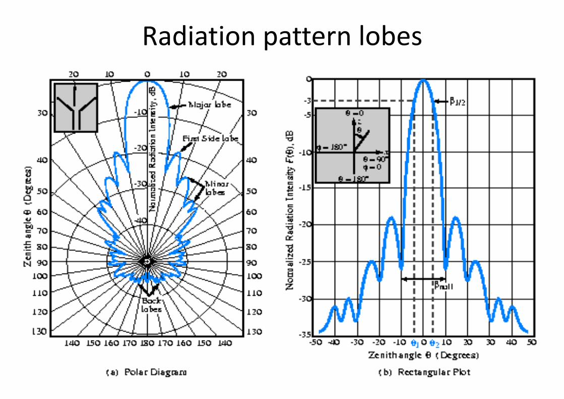
Radiation pattern lobes

Pattern Lobes
• Pattern lobe is a portion of the radiation pattern with a local maximum
– Lobes are classified as: major, minor, side lobes, back lobes.
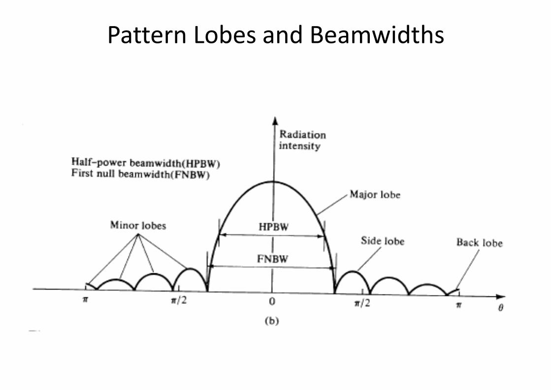
Pattern Lobes and Beamwidths

Beamwidth - half-power beamwidth and first null beamwidth
• The width of the main beam or major lobe in terms of angles or radians.
• Half-power beamwidth (also known as 3dB beamwidth) and first null beamwidth is of interest
• 3dB beamwidth - In a radiation pattern cut containing the direction of the maximum of a lobe, the angle between the two directions in which the radiation intensity is one-half the maximum value
• Normally related to the resolution
• Narrow beam requires large antenna dimensions
• First-null beamwidth – In a radiation pattern cut, the angle between the two nulls adjacent to the main beam
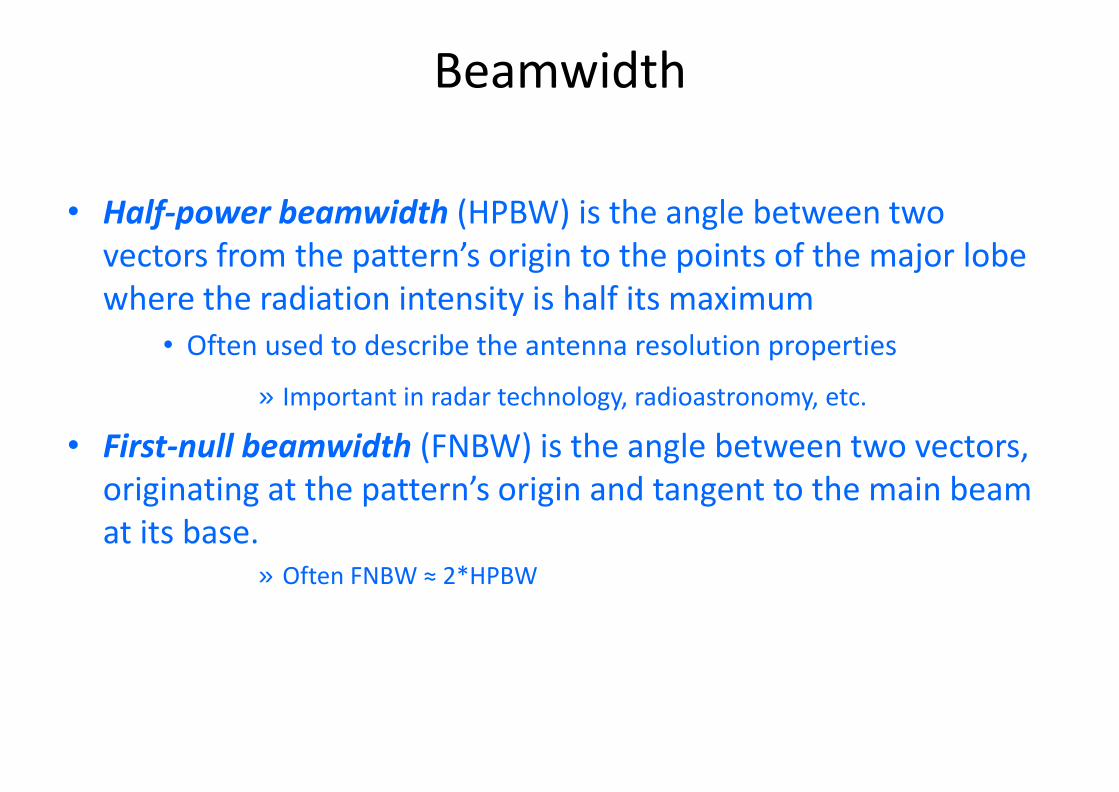
Beamwidth
• Half-power beamwidth (HPBW) is the angle between two vectors from the pattern’s origin to the points of the major lobe where the radiation intensity is half its maximum
• Often used to describe the antenna resolution properties
» Important in radar technology, radioastronomy, etc.
• First-null beamwidth (FNBW) is the angle between two vectors, originating at the pattern’s origin and tangent to the main beam at its base.
» Often FNBW ≈ 2*HPBW

Radiation Resistance
• An antenna’s radiation resistance is a measure of its ability to radiate an applied signal into space, or to receive a signal from space.
• The radiation resistance is not a real (dissipative) resistance, but a measure of the power radiated into free-space for a given input current.
• The important observation about radiation resistance is that, for a given current into the antenna, as radiation resistance increases, so does the antenna’s efficiency.

Radiation resistance
fqqq
2
222
0
3
2
222
2
0 0
22
22
222
12
sin232
sinsin32
LI
dLI
ddrr
LI
dSPP
m
m
m
averad
Radiation resistance Rr of an antenna is the hypothetical resistance that would dissipate the same amount of power as the radiated power Rr.
Lets find the radiation resistance for a short dipole:
First find the total power radiated

2
2
240 mrad IL
P
2
2
22 402
1mrmrad I
LRIP
2
280
LRr
Replace and ,
The power is equivalent to the power dissipated in a fictitious resistance Rr by a current Im
Thus, the radiation resistance is given by,

2.7 Reflection Coefficient
The reflection coefficient of a transmitting antenna is
defined by:
Z A Z0
can be calculated (as above) or measured. The
of is from 0 magnitude to 1. When the transmitting
antenna is not macth, i.e., ZA ≠ Z0, there is a loss due to reflection (return loss) of the wave at the antenna
dB, terminals. When expressed in is always a
to represent . negative number. Sometimes we use S11
Z A Z0 (dimensionless)

2.8 Return Loss
The return loss of a transmitting antenna is defined by:
to ∞ Possible values of return loss are from 0 dB dB.
Return loss is always a positive number.
return loss 20 log (dB)

Standing Wave ratio: The ratio of maximum to minimum voltages along a finite terminated line is called standing wave ratio.

2.9 VSWR
The voltage standing wave ratio (VSWR) of a
transmitting antenna is defined by:
1
Same as and the return loss,
parameter used to characterize
VSWR is also a common
the matching property of
a transmitting antenna. Possible values of VSWR are
VSWR=1 from 1 to ∞. perfectly matched. VSWR =
∞ completely unmatched.
VSWR 1
(dimensionless)

2.10
Impedance Bandwidth
or S11 (dB)
-10dB
Frequency Impedance bandwidth
fL fC fU

fC
when Note that = -10 dB,
Impedance bandwith fU f L 100%
Prob: What will be the VSWR if the reflection coefficient is -10dB

fC
when Note that = -10 dB,
1 =
1 0.3162 VSWR 1 1 0.3162
=1.93
2
Hence the impedance bandwidth can also be specified
2. by the frequency range within which VSWR
Impedance bandwith fU f L 100%

Prob: Calculate reflection coefficient having SWR of 1.5.
• Soln:

Prob: Calculate reflection coefficient having SWR of 1.5.
• Soln:
return loss or reflection coefficient 20 log (dB)

Prob: Calculate the radiation resistance of an antenna having wavelength 5 λ = and length 25cm.

Prob: Calculate the radiation resistance of an antenna having wavelength 5 λ = and length 25cm.

Prob: The maximum power density radiated by a short dipole at a distance of 1 km is 60 (nW/m2). If I0 = 10 A, find the radiation resistance.

Prob: The maximum power density radiated by a short dipole at a distance of 1 km is 60 (nW/m2). If I0 = 10 A, find the radiation resistance.

Prob: The effective area of an antenna is 9 m2. What is its directivity in decibels at 3 GHz?
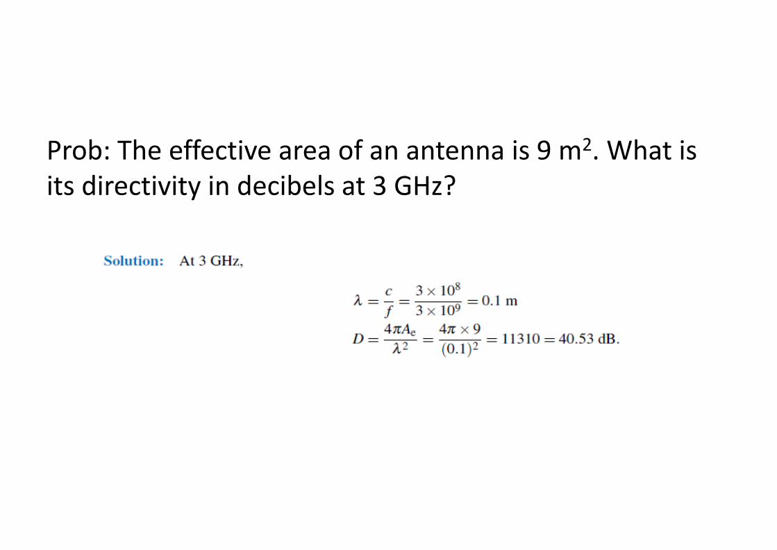
Prob: The effective area of an antenna is 9 m2. What is its directivity in decibels at 3 GHz?

Prob: At 100 MHz, the pattern solid angle of an antenna is 1.3 sr. Find (a) the antenna directivity D and (b) its effective area Ae.
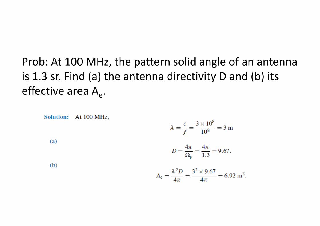
Prob: At 100 MHz, the pattern solid angle of an antenna is 1.3 sr. Find (a) the antenna directivity D and (b) its effective area Ae.
• Problem: The effective area of a parabolic dish antenna is approximately equal to its physical aperture. If the directivity of a dish antenna is 30 dB at 10 GHz, what is its effective area? If the frequency is increased to 30 GHz, what will be its new directivity?

• Problem: The effective area of a parabolic dish antenna is approximately equal to its physical aperture. If the directivity of a dish antenna is 30 dB at 10 GHz, what is its effective area? If the frequency is increased to 30 GHz, what will be its new directivity?

Problem: Determine the effective area of a half-wave dipole antenna at 100 MHz, if the wire diameter is 2 cm.

Problem: Determine the effective area of a half-wave dipole antenna at 100 MHz, if the wire diameter is 2 cm.

73
Terminology
Antenna – structure or device used to collect or radiate electromagnetic waves
Array – assembly of antenna elements with dimensions, spacing, and illumination sequency such that the fields of the individual elements combine to produce a maximum intensity in a particular direction and minimum intensities in other directions
Beamwidth – the angle between the half-power (3-dB) points of the main lobe, when referenced to the peak effective radiated power of the main lobe
Directivity – the ratio of the radiation intensity in a given direction from the antenna to the radiation intensity averaged over all directions
Effective area – the functional equivalent area from which an antenna directed toward the source of the received signal gathers or absorbs the energy of an incident electromagnetic wave
Efficiency – ratio of the total radiated power to the total input power
Far field – region where wavefront is considered planar
Gain – ratio of the power at the input of a loss-free isotropic antenna to the power supplied to the input of the given antenna to produce, in a given direction, the same field strength at the same distance
Isotropic – radiates equally in all directions
Main lobe – the lobe containing the maximum power
Null – a zone in which the effective radiated power is at a minimum relative to the maximum effective radiation power of the main lobe
Radiation pattern – variation of the field intensity of an antenna as an angular function with respect to the axis
Radiation resistance – resistance that, if inserted in place of the antenna, would consume that same amount of power that is radiated by the antenna
Side lobe – a lobe in any direction other than the main lobe

Friis Transmission Formula
At=Transmitting Effective Area
Ar=Receiving Effective Area
R = Distance between antennas
Pt= Transmitter power supplied to
transmitting antenna
Prad= Actually radiated power from
transmitting antenna
Pint= Intercepted power at receiving antenna
= Radiation efficiency of transmitting
antenna
= Radiation efficiency of receiving
antenna
= Directivity of transmitting antenna
t
r24 R
PS t
iso
Power density incident upon receiving
antenna at a distance R from an isotropic
lossless transmitting antenna
-----------------(9.71)
For real transmitting antenna received
power density
24 R
PDSDSGS ttt
isottisotr
-(9.72)
tD

We know effective area of any antenna is defined by
Using Eq. (9.64), Eq. (9.72) can be expressed in terms of the effective area
---------------------------------------------------------------(9.73)
Power intercepted by receiving antenna = Incident power density × Effective area
The received power delivered to the receiver = Intercepted power × radiation efficiency of the receiving antenna
This relation is known as the Friis Transmission Formula and is sometimes called the power transfer ratio.
Where and are gain of transmitting and receiving antenna.
4
2DAe --------------------------------------------------------------------(9.64)
tA
22R
PAS ttt
r
rSrA
22intR
PAAASP trtt
rr
-----------------------------------------------------(9.74)
recP intP
r
2
22)
4(
RGG
R
AA
P
Prt
rtrt
t
rec
-------------------------------------------------(9.75)
t
rec
P
P
tG rG

Satellite Communication System: Problem 1: A 6 GHz direct-broadcast TV satellite system transmits 100W through a 2 m diameter parabolic dish antenna from a distance of approximately 40,000 km above Earth’s surface. Each TV channel occupies a bandwidth of 5 MHz. Due to electromagnetic noise picked up by the antenna as well as noise generated by the receiver electronics, a home TV receiver has a noise level given by Pn = KTsysB (W), (9.71) where Tsys [measured in kelvins (K)] is a figure of merit called the system noise temperature that characterizes the noise performance of the receiver–antenna combination, K is Boltzmann’s constant [1.38×10⁻²³ (J/K)], and B is the receiver bandwidth in Hz. The signal-to-noise ratio Sn (which should not be confused with the power density S is defined as the ratio of Prec to Pn: Sn = Prec/Pn (dimensionless). (9.72) For a receiver with Tsys = 580 K, 1) what minimum diameter of a parabolic dish receiving antenna is required for high-qualityTV reception with Sn = 40 dB? The satellite and ground receiving antennas may be assumed lossless, and their effective areas may be assumed equal to their physical apertures.


Problem 2: If the operating frequency of the communication system described in Problem 1 is doubled to 12 GHz, what would then be the minimum required diameter of a home receiving TV antenna?

Problem 2: If the operating frequency of the communication system described in Example 9-5 is doubled to 12 GHz, what would then be the minimum required diameter of a home receiving TV antenna?

Problem 3: A 3-GHz microwave link consists of two identical antennas each with a gain of 30 dB. Determine the received power, given that the transmitter output power is 1 kW and the two antennas are 10 km apart.

Problem 3: A 3-GHz microwave link consists of two identical antennas each with a gain of 30 dB. Determine the received power, given that the transmitter output power is 1 kW and the two antennas are 10 km apart.

Problem 4: A 3-GHz line-of-sight microwave communication link consists of
two lossless parabolic dish antennas, each 1 m in diameter. If the receive antenna requires 10 nW of receive power for good reception and the distance between the antennas is 40 km, how much power should be transmitted?

Problem 4: A 3-GHz line-of-sight microwave communication link consists of
two lossless parabolic dish antennas, each 1 m in diameter. If the receive antenna requires 10 nW of receive power for good reception and the distance between the antennas is 40 km, how much power should be transmitted?

Problem 5: A half-wave dipole TV broadcast antenna transmits 1 kW at 50MHz. What is the power received by a home television antenna with 3-dB gain if located at a distance of 30 km?

Problem 5: A half-wave dipole TV broadcast antenna transmits 1 kWat 50MHz. What is the power received by a home television antenna with 3-dB gain if located at a distance of 30 km?

Problem 6 A 150-MHz communication link consists of two vertical half-wave dipole antennas separated by 2 km. The antennas are lossless, the signal occupies a bandwidth of 3 MHz, the system noise temperature of the receiver is 600 K, and the desired signal-to-noise ratio is 17 dB. What transmitter power is required?


POLARIZATION
• The polarization of an antenna is the orientation of the electric field with respect to the Earth's surface and is determined by the physical structure of the antenna and by its orientation.
• Radio waves from a vertical antenna will usually be vertically polarized.
• Radio waves from a horizontal antenna are usually horizontally polarized.

Direction of Propagation
Direction of Propagation

Horizontally polarized directional yagi antenna
Vertically polarized omnidirectional dipole antenna

Ex Ex Ex
Eectric-field vector vector Eectric-field vector
Linearly polarized Elliptically polarized Circularly polarized
See animation “Polarization of a Plane Wave - 3D View”
See animation “Polarization of a Plane Wave - 2D View”
Eectric-field
Eectric-fi
Ey
Eectric-field

Polarization of Plane Waves
(a) Linear polarization
A plane wave is linearly polarized at a fixed
observation point if the tip of the electric-field
vector at that point moves along the same
straight line at every instant of time.
Circular Polarization
A plane wave is circularly polarized at a a fixed
observation point if the tip of the electric-field
(b)
vector at that point traces out a circle as a
function of time.

Circular polarization can be either right-handed
or left-handed corresponding to the electric-field
vector rotating clockwise (right-handed) or anti-
clockwise (left-handed).
Elliptical Polarization
A plane wave is elliptically polarized at a a fixed
(c)
observation point if the tip of the electric-field
vector at that point traces out an ellipse as a
function of time. Elliptically polarization can be
either right-handed or left-handed corresponding
to the electric-field vector rotating clockwise
(right-handed) or anti-clockwise (left-handed).

EE5308
Axial Ratio
The polarization state of an EM wave can also be
indicated by another two parameters: Axial Ratio
(AR) and the tilt angle (). AR is a common measure
for antenna polarization. It definition is:
OB
where OA and OB are
the polarization ellipse,
the major and minor axes of
angle respectively. The tilt
is the angle subtended by the major axis of the
polarization ellipse and the horizontal axis.
29
AR OA
, 1 AR , or 0 dB AR dB

= tilt angle 0 ≤ ≤ 180º

For example:
AR = 1,
1 < AR <
AR = ,
circular polarization
elliptical polarization
linear polarization
,
Very often, we use the AR bandwidth and the AR
beamwidth to characterize the polarization of an antenna.
The AR bandwidth is the frequency bandwidth in which
the AR of an antenna changes less than 3 dB from its
minimum value. The AR beamwidth is the angle span
over which the AR of an antenna changes less than 3 dB
from its mimumum value.
AR can be measured experimentally!

3 dB AR beamwidth
Radiation pattern
with a rotating
linear source
q
AR at q in dB scale
Test antenna
(receiving) Fast-rotating dipole
antenna (transmitting)

Axial ratio (dB)
uency
3dB
AR bandwidth Freq

Thank You


1
0
3
Friis’ transmission formula
At a fixed distance R from the transmitting antenna, the power intercepted by the receiving antenna with effective aperture Ar is
where Sr is the received power density (W/m2), and Gt is the peak gain of the transmitting antenna.
rtt
rri AGR
PASP
24