ANSYS Advantage Multiphysics AA V8 I2
60
Excellence in Engineering Simulation VOLUME VIII | ISSUE 2 | 2014 ADVANTAGE ADVANTAGE ™ SPOTLIGHT ON MULTIPHYSICS 6 Multiphysics: The Future of Simulation 11 Robust Electric Machine Design Through Multiphysics 16 Magnetic Appeal
description
Ansys Magazine
Transcript of ANSYS Advantage Multiphysics AA V8 I2

Excellence in Engineering Simulation VOLUME VIII | ISSUE 2 | 2014
ADVANTAGEADVANTAGE™
SPOTLIGHT ONMULTIPHYSICS
6Multiphysics:
The Future of Simulation11
Robust Electric Machine Design Through Multiphysics
16Magnetic Appeal

Realize Your Product Promise®ANSYS is dedicated exclusively to developing engineering simulation software that fosters rapid and innovative product design. ANSYS technology enables you to predict with confidence that your product will thrive in the real world. For more than 40 years, customers in the most demanding markets have trusted our solutions to help ensure the integrity of their products and drive business success through innovation.
ANSYS, Inc. Southpointe 275 Technology Drive Canonsburg, PA 15317 U.S.A.
For ANSYS, Inc. sales information, call 1.866.267.9724.Email the editorial staff at [email protected]. For address changes, contact [email protected].
Neither ANSYS, Inc. nor Agency 1903 guarantees or warrants accuracy or completeness of the material contained in this publication.ANSYS, ALinks, Ansoft Designer, Aqwa, Asas, Autodyn, BladeModeler, CFD, CFX, Chip Power Module (CPM), Chip Thermal Model (CTM), DesignerRF, DesignerSI, DesignModeler, DesignSpace, DesignXplorer, Engineering Knowledge Manager (EKM), Explicit STR, Fatigue, Fluent, Full-Wave SPICE, HFSS, ICEM CFD, Icepak, Icepro, Maxwell, Mechanical, Mesh Morpher, Multiphysics, Nexxim, Optimetrics, ParICs, PathFinder, PExprt, Polyflow, PowerArtist, PowerArtist Calibrator and Estimator (PACE), Professional, Q3D Extractor, QuickEye, Realize Your Product Promise, RedHawk, Rigid Dynamics, RMxprt, RTL Power Model (RPM), SCADE Display, SCADE Lifecycle, SCADE Suite, SCADE System, Sentinel, SIwave, Simplorer, Simulation-Driven Product Development, Solver on Demand, Structural, Super-Compact, TGrid, Totem, TPA, TurboGrid, Vista TF, VerifEye, WinIQSIM, Workbench, and any and all ANSYS, Inc. brand, product, service, and feature names, logos and slogans are registered trademarks or trademarks of ANSYS, Inc. or its subsidiaries located in the United States or other countries.ICEM CFD is a trademark licensed by ANSYS, Inc. LS-DYNA is a registered trademark of Livermore Software Technology Corporation. nCode DesignLife is a trademark of HBM nCode. All other brand, product, service, and feature names or trademarks are the property of their respective owners.
Executive Editor Fran Hensler
Managing Editor Chris Reeves
Editors Erik Ferguson Kara Gremillion Mark Ravenstahl Judy Cooper Verly Flores
Editorial Advisor Tom Smithyman
Editorial Contributor ANSYS North America Support and Services
Art Directors Ron Santillo Dan Hart
Design Agency 1903
W elcome to ANSYS Advantage! We hope you enjoy this issue containing articles by ANSYS customers, staff and partners. Want to be part of a future issue? The editorial team is interested in your ideas for an article. Contact us.
The Editorial Staff, ANSYS [email protected]
© 2014 ANSYS, Inc.
Subscribe at ansys.com/magazine
Join the simulation conversation ansys.com/Social@ANSYS
Past issues of ANSYS Advantage are always available at
ansys.com/archive
Get Caught Up
© 2014 ANSYS, INC. ANSYS ADVANTAGE Volume VIII | Issue 2 | 2014 1
ELIMINATING THE ELEMENT OF SURPRISE
Today’s sophisticated products bring together a range of complex parts and functionality. Multiphysics simulation is critical in understanding how these parts actually work together in their operating environment — and managing the critical risk of product failure.By Josh Fredberg, Vice President of Marketing, ANSYS, Inc.
EDITORIAL
Designing products can be relatively straightfor-ward when they are simple, contain just a few parts and perform a single function — and when operating conditions can be perfectly controlled. But as every engineer knows, this is not the world in which we live, 2014.
Today’s products are more complex, and deliver more sophis-ticated functionality, than ever before. Consider the simple design and few moving parts of a rotary telephone versus the advanced engineering that goes into every smartphone.
While not all products have been transformed so dramati-cally, engineers in every industry recognize that their designs are growing in complexity. The integration of smart electronics in our everyday appliances and the increasingly digital nature of our cars represent just two very visible examples of a quiet revolution that has occurred in engineering over the past decade.
Just as engineering has evolved from relying on paper calcu-lations and physical experiments to leveraging computer simula-tion, our tools and methods must continue to evolve to reflect the incredible complexity of today’s products. Engineers can no longer be guided by even the most general assumptions about how their designs will perform — or focus on the one physical force that seems most important. Instead, they require a new toolset that brings together a full range of physical phenomena, accurately replicat-ing the physical environment in which their designs will operate.
Multiphysics simulation enables engineers to understand and weigh the trade-offs they make when they improve one aspect of their product’s complex performance. For example, if turboma-chinery engineers focus on blade weight reduction, they risk affect-ing structural deformation and flow path performance. As electron-ics engineers seek ever-smaller footprints, they must minimize stress and failure rates caused by heat build-up. Electric motor designers can easily assess how their focus on weight reduction and greater energy efficiency impacts acoustic performance. None
While multiphysics analysis was once the domain of only the most advanced users, today ANSYS has democratized this technology, making it possible for every engineering team to couple physics and assess performance at the systems level.
of these trade-offs is observable if engineers apply only a single physics during the product development process.
For more than 40 years, ANSYS has focused on perfecting software and methods to model the effects of real-world thermal, mechanical, electromagnetic and fluidic forces. Today, our empha-sis is on seamlessly integrating these capabilities to support fast, accurate multiphysics simulations of both on-design and off-design product performance.
While multiphysics analysis was once the domain of only the most advanced users, today ANSYS has democratized this technol-ogy, making it possible for every engineering team to couple phys-ics and assess performance at the systems level. According to our own research, 34 percent of ANSYS users today are analyzing mul-tiple physics — and that number grows daily.
In the hyper-competitive global marketplace, multiphysics simulation is just one more weapon in the arsenal of product devel-opment teams. It enables them to not only be first to market, but also to lead in product quality and brand reputation.
What are the costs of failing to evolve — and of overlooking the exciting possibilities of multiphysics simulation? Unfortunately, recent headlines draw negative attention to many companies who failed to anticipate how disparate components would work together, or even how users would hold a product in their hands while using it.
ANSYS offers the broadest and deepest multiphysics capabilities available to help mitigate this risk. This issue of ANSYS Advantage features many inspiring examples of engineering leaders who are applying ANSYS software in a multiphysics manner to combine extreme speed with extreme confidence as they develop new products.
However, at ANSYS we don’t rest on our laurels. We continue to work to make it easier, faster and more seamless to illuminate the effects of multiple physical forces on our customers’ most complex designs. As products continue to grow in sophistication, ANSYS software will also continue to evolve — anticipating and meeting a new generation of multiphysics simulation needs.
© 2014 ANSYS, INC. ANSYS ADVANTAGE Volume VIII | Issue 2 | 2014 2
16 20 24
TABLE OF CONTENTS
FEATURES
6BEST PRACTICES
Multiphysics: The Future of SimulationAs part of its comprehensive set of solutions for engineering simulation, ANSYS introduces new technology developments that make multiphysics simulations faster, more seamless and higher fidelity — as well as more accessible than ever.
11ROBUST ELECTRIC MACHINE DESIGN
Robust Electric Machine Design Through MultiphysicsElectromagnetic, mechanical and thermal simulation plus design optimization help to improve energy efficiency, noise and bearing life of robust electric motors.
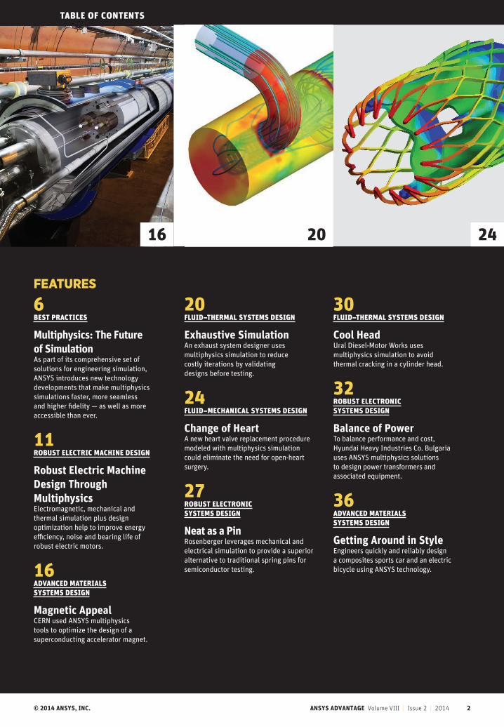
16ADVANCED MATERIALS SYSTEMS DESIGN
Magnetic AppealCERN used ANSYS multiphysics tools to optimize the design of a superconducting accelerator magnet.
20FLUID–THERMAL SYSTEMS DESIGN
Exhaustive SimulationAn exhaust system designer uses multiphysics simulation to reduce costly iterations by validating designs before testing.
24FLUID–MECHANICAL SYSTEMS DESIGN
Change of HeartA new heart valve replacement procedure modeled with multiphysics simulation could eliminate the need for open-heart surgery.
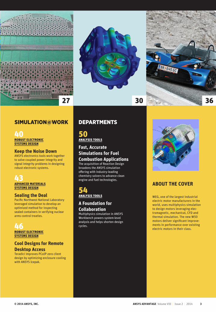
27ROBUST ELECTRONIC SYSTEMS DESIGN
Neat as a PinRosenberger leverages mechanical and electrical simulation to provide a superior alternative to traditional spring pins for semiconductor testing.
30FLUID–THERMAL SYSTEMS DESIGN
Cool HeadUral Diesel-Motor Works uses multiphysics simulation to avoid thermal cracking in a cylinder head.
32ROBUST ELECTRONIC SYSTEMS DESIGN
Balance of PowerTo balance performance and cost, Hyundai Heavy Industries Co. Bulgaria uses ANSYS multiphysics solutions to design power transformers and associated equipment.
36ADVANCED MATERIALS SYSTEMS DESIGN
Getting Around in StyleEngineers quickly and reliably design a composites sports car and an electric bicycle using ANSYS technology.
© 2014 ANSYS, INC. ANSYS ADVANTAGE Volume VIII | Issue 2 | 2014 3
w27 30 36
SIMULATION@WORK DEPARTMENTS
40ROBUST ELECTRONIC SYSTEMS DESIGN
Keep the Noise DownANSYS electronics tools work together to solve coupled power integrity and signal integrity problems in designing robust electronic systems.
43ADVANCED MATERIALS SYSTEMS DESIGN
Sealing the DealPacific Northwest National Laboratory leveraged simulation to develop an optimized method for inspecting sealed containers in verifying nuclear arms control treaties.
46ROBUST ELECTRONIC SYSTEMS DESIGN
Cool Designs for Remote Desktop AccessTeradici improves PCoIP zero client design by optimizing enclosure cooling with ANSYS Icepak.
50ANALYSIS TOOLS
Fast, Accurate Simulations for Fuel Combustion ApplicationsThe acquisition of Reaction Design broadens the ANSYS simulation offering with industry-leading chemistry solvers to advance clean engine and fuel technologies.
54ANALYSIS TOOLS
A Foundation for CollaborationMultiphysics simulation in ANSYS Workbench powers system-level analysis and helps shorten design cycles.
ABOUT THE COVER
WEG, one of the largest industrial electric motor manufacturers in the world, uses multiphysics simulation to design motors leveraging elec-tromagnetic, mechanical, CFD and thermal simulation. The new W50 motors deliver significant improve-ments in performance over existing electric motors in their class.
© 2014 ANSYS, INC. ANSYS ADVANTAGE Volume VIII | Issue 2 | 2014 4
NEWS
Simulation in the NewsEDITOR’S PICK: ELECTROMAGNETIC SUITE SIMULATES PCB AND IC DESIGNSDesktop Engineeringdeskeng.com, April 2014
Because minimizing EMI and ensur-ing integrity is important to current and future product development, ANSYS recently expanded its 3-D electromag-netic simulation suite for the design of high-speed PCBs and IC packages. ANSYS SIwave includes new functionality and three new targeted analysis products: SIwave-DC, SIwave-PI and SIwave. The suite helps designers to quickly identify potential power and signal integrity prob-lems, offering the tools needed to evaluate an entire design from package to board, including the coupling effects between traces, packages and boards.
TURBOMACHINERY SIMULATION KEY TO WIND ENERGY AND ENERGY EFFICIENCYTechWeektechweek.es, March 2014
The recent European Wind Energy Association in Barcelona brought together wind industry experts to discuss how to improve energy efficiency. Gilles Lebiez from ANSYS discussed turbomachinery simulation, noting that “wind energy is increasing its contribution to the mix overall. Although turbomachinery appli-cations are incredibly diverse, efficiency is a common challenge for all design engi-neers.” ANSYS simulation software helps to ensure that critical systems are also reliable, secure and low-maintenance.
TURBULENCE MODELING: NEW SOLUTIONS FOR (ALMOST) EVERY INDUSTRYHigh Performance Computinghpcmagazine.com, February 2014
Because turbulence is a very complex phenomenon, no single do-it-all formula-tion has been found to date. The challenge for CFD software developers is to incorpo-rate the right subset of models, resulting in a package that is robust, accurate and validated — and that covers applications that users need. Gilles Eggenspieler from ANSYS discusses how various industries and applications can benefit from the appropriate turbulence modeling.
ANSYS LOVES SPACECLAIM SO MUCH THEY JUST BOUGHT IT3D Printing Industry3dprintingindustry.com, May 2014
SpaceClaim Corporation, a leading pro-vider of fast and intuitive 3-D model-ing software for engineers, is now part of ANSYS. The two companies part-nered previously to offer customers ANSYS SpaceClaim Direct Modeler, but this more formal union fulfills the long-time vision of Simulation-Driven Product Development, in which organizations can derive tremendous value by harnessing computer simulation early in the design cycle to predict how a product will per-form in the real world.
ANSYS DEBUTS REDHAWK FOR POWER NOISE AND RELIABILITY SIGN-OFF PLATFORMEDACaféedacafe.com, April 2014
The latest version of ANSYS RedHawk offers greater performance, capacity and coverage as well as sign-off accuracy to address the challenges faced by the increasing complexity of FinFET-based designs. While FinFET brings greater per-formance, capacity and coverage, these designs experience smaller noise and reli-ability margins, which require tighter con-trol over analysis accuracy. The release incorporates technologies that enable the simulation of 100 M+ instances or 2 B+ node designs, while maintaining flat sim-ulation accuracy for sign-off.
SpaceClaim’s 3-D tools — combined with ANSYS’ proven simulation software — are ideally suited to the rapid pace of today’s business.
― Daniel Dean, Senior Vice President,Research and Development,
SpaceClaim
As CFD applications become more complex, more sophisticated turbulence models are needed.
© 2014 ANSYS, INC. ANSYS ADVANTAGE Volume VIII | Issue 2 | 2014 5
EDA TOOLSElettronica Pluselettronica-plus.it, March 2014
The electronics industry in Italy is seeing new growth in 2014, and ANSYS stands ready to create a strong synergy with cus-tomers, understand their goals and help them succeed in the shortest time possi-ble, according to Massimo Capodiferro of ANSYS. “The goal of every engineer is to predict device behavior before they dis-cover problems in the lab that delay the delivery of a product. Our customers have indicated the need to simulate increas-ingly complex systems that can integrate circuit elements and system elements and finally predict the electromagnetic inter-actions between multiple individuals within the same device.”
VEHICLE AERODYNAMICS: DRAG REDUCTION THROUGH SURFACE DIMPLESThe Borneo Posttheborneopost.com, April 2014
Based on the concept that a dimpled golf ball can travel higher and farther than a smooth-surfaced golf ball, a Curtin University Sarawak student investigated the energy-saving effects of dimples on a car body. Chear Chie Khan used an ANSYS Fluent turbu-lence model to show that the coefficient of drag, CD, is reduced by 1.9 percent when a dimple is introduced onto the car surface.
VIRTUAL SYSTEM PROTOTYPING FOR ELECTROMECHANICAL SYSTEMSEngineering.comEngineering.com, March 2014
Creating a virtual systems prototype that simulates the complex interactions of electromechanical systems — including the embedded code that controls the systems — is a demanding job. Todd McDevitt of ANSYS states, “The secret to producing a high-fidelity virtual systems prototype is producing a good reduced-order model.” The engineering team needs multiphysics simulation tools for mechan-ical, fluid dynamics, thermal, electronic and embedded software development along with a multi-domain system simulation software to provide input for the virtual systems prototype. At each iteration, the design team improves the fidelity of the subsystem and com-ponent-level models, eventually reaching a virtual systems prototype that can be used for more sophisticated design optimization.
WHEN NATURE GIVES UP, ENGINEERING CAN GIVE HEARTS A HANDMedical Design Briefsmedicaldesignbriefs.com, April 2014
Systematic adoption of engineering sim-ulation by medical device companies is accelerating innovation that addresses cardiac disorders, including stents, min-imally invasive surgical procedures, arti-ficial valves and artificial heart-assist devices. Thierry Marchal from ANSYS dis-cusses the opportunities, restrictions and best practices in this growing field.
COMPREHEND COMPOSITE COMPLEXITIESComposites in Manufacturingcomposites-manufacturing.com, February 2014
The anisotropic properties of composite materials have created a fourth dimension in mechanical design, as opposed to the 3-D isotropic properties of traditional materials, according to Marc Wintermantel of ANSYS. “When a designer uses simulation software to define composite part points in space, he has a tremendous amount of additional design options and parameters to deal with,” he explains. “These options are so large that you need to depend on optimized simulation tools because the computations go
way beyond most people’s abilities to perform these tasks by hand.” Wintermantel and ANSYS colleague Pierre Thieffry discuss how simula-tion can lead to faster composites designs that accurately mirror real-world performance.
ANSYS AND GENERAL ELECTRIC UNLOCK FUTURE INNOVATION WITH NEW COLLABORATION AGREEMENTFinanzNachrichtenfinanznachrichten.de, May 2014
GE Aviation and ANSYS are deepening their long-standing strategic relationship by establishing a new joint technology collaboration agreement that will help to solve future engineering challenges and drive product development processes in a world of smart products and big data. ANSYS and GE Aviation will work together over a range of applications to establish forward-looking analysis techniques that leverage expertise from both parties. In the first project under this agreement, ANSYS and GE Aviation will investigate industry data to create new engineering best practices associated with the accurate analysis of some of GE’s core industrial products.
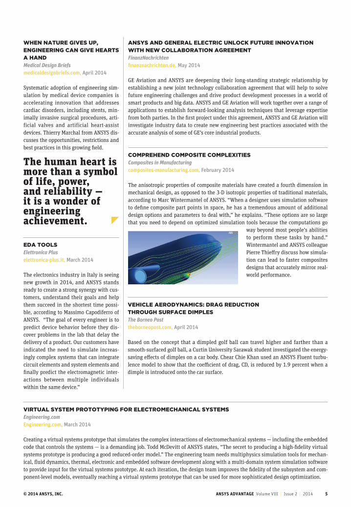
The human heart is more than a symbol of life, power, and reliability — it is a wonder of engineering achievement.

© 2014 ANSYS, INC. ANSYS ADVANTAGE Volume VIII | Issue 2 | 2014 6
BEST PRACTICES
By Chris Wolfe, Lead Product Manager for Multiphysics, ANSYS
Multiphysics:
THE FUTURE of SIMULATIONAs part of its comprehensive set of solutions for engineering simulation, ANSYS introduces new technology developments that make multiphysics simulations faster, more seamless and higher-fidelity — as well as more accessible than ever.
© 2014 ANSYS, INC. ANSYS ADVANTAGE Volume VIII | Issue 2 | 2014 7
Engineering simulation plays a role in designing the buildings we live and work in, the cars we drive,
the smartphones we carry, the medical devices that keep us healthy, our comput-ers, our food and much more. Since ANSYS first introduced simulation software more than four decades ago, it has dramati-cally grown in its adoption by engineering teams around the world, in every indus-try, in every discipline.
Today, the majority of the world’s engineering teams apply simulation tools and methods in the design phases of prod-uct development, replacing costly physi-cal prototyping and testing with advanced numerical analyses.
Historically, engineers had to apply some degree of simplification to their simulations to meet product deadlines while improving those aspects of perfor-mance most valued by users. This often meant focusing on the single most impor-tant physical phenomenon affecting the product.
For example, designers of Formula 1 cars traditionally devoted resources to improving aerodynamics via computa-tional fluid dynamics (CFD) simulations. Designers of construction or agricultural equipment leveraged mechanical simula-tion software to optimize products’ ability to withstand heavy forces. Manufacturers of printed circuit boards (PCBs) invested the majority of their efforts in ensuring signal integrity.
This historic focus on a single physics yielded useful insights into critical prod-uct characteristics, often resulting in sig-nificant performance gains — at a lower investment of time and money than tra-ditional experimental and physical pro-totyping methods. But, as competitive pressures have increased and consumers have become more sophisticated in their demands, today it is rare to achieve the best-possible product design when opti-mizing a product’s response to a single physical force. To understand every force at play, and accurately predict if the prod-uct can perform well as a result, all the relevant physics need to be considered.
Being able to simulate all physics at the same time — and perform para-metric optimization using multiphys-ics results — allows engineers to quickly gain important insight into product per-formance, target optimal designs faster, and release products to market earlier.
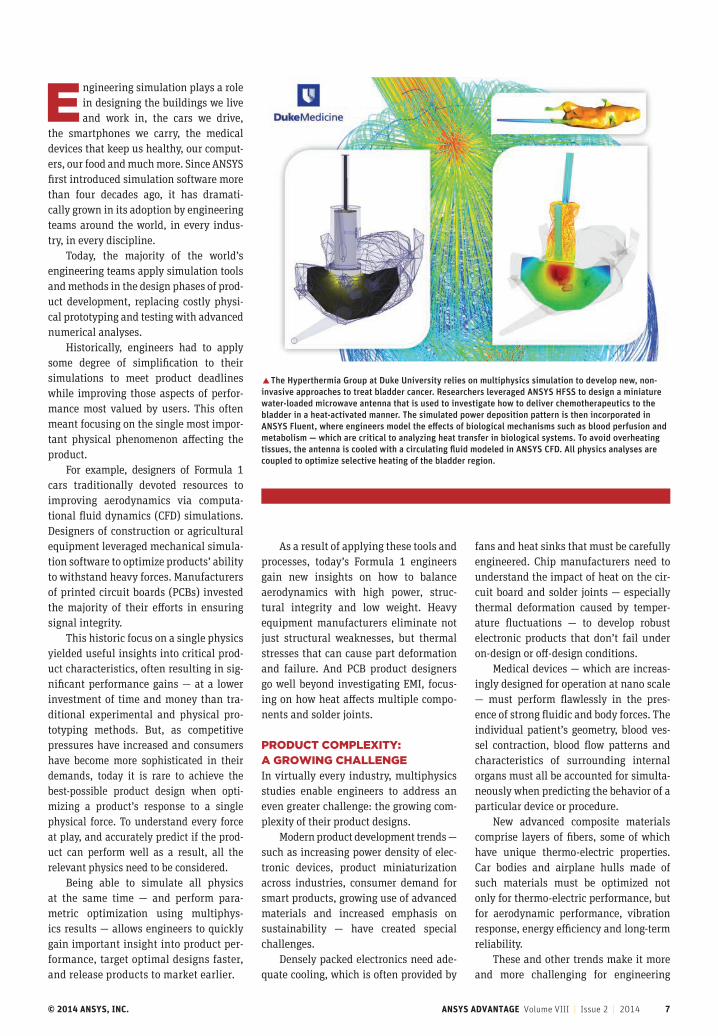
�The Hyperthermia Group at Duke University relies on multiphysics simulation to develop new, non-invasive approaches to treat bladder cancer. Researchers leveraged ANSYS HFSS to design a miniature water-loaded microwave antenna that is used to investigate how to deliver chemotherapeutics to the bladder in a heat-activated manner. The simulated power deposition pattern is then incorporated in ANSYS Fluent, where engineers model the effects of biological mechanisms such as blood perfusion and metabolism — which are critical to analyzing heat transfer in biological systems. To avoid overheating tissues, the antenna is cooled with a circulating fluid modeled in ANSYS CFD. All physics analyses are coupled to optimize selective heating of the bladder region.
As a result of applying these tools and processes, today’s Formula 1 engineers gain new insights on how to balance aerodynamics with high power, struc-tural integrity and low weight. Heavy equipment manufacturers eliminate not just structural weaknesses, but thermal stresses that can cause part deformation and failure. And PCB product designers go well beyond investigating EMI, focus-ing on how heat affects multiple compo-nents and solder joints.
PRODUCT COMPLEXITY: A GROWING CHALLENGEIn virtually every industry, multiphysics studies enable engineers to address an even greater challenge: the growing com-plexity of their product designs.
Modern product development trends — such as increasing power density of elec-tronic devices, product miniaturization across industries, consumer demand for smart products, growing use of advanced materials and increased emphasis on sustainability — have created special challenges.
Densely packed electronics need ade-quate cooling, which is often provided by
fans and heat sinks that must be carefully engineered. Chip manufacturers need to understand the impact of heat on the cir-cuit board and solder joints — especially thermal deformation caused by temper-ature fluctuations — to develop robust electronic products that don’t fail under on-design or off-design conditions.
Medical devices — which are increas-ingly designed for operation at nano scale — must perform flawlessly in the pres-ence of strong fluidic and body forces. The individual patient’s geometry, blood ves-sel contraction, blood flow patterns and characteristics of surrounding internal organs must all be accounted for simulta-neously when predicting the behavior of a particular device or procedure.
New advanced composite materials comprise layers of fibers, some of which have unique thermo-electric properties. Car bodies and airplane hulls made of such materials must be optimized not only for thermo-electric performance, but for aerodynamic performance, vibration response, energy efficiency and long-term reliability.
These and other trends make it more and more challenging for engineering
© 2014 ANSYS, INC. ANSYS ADVANTAGE Volume VIII | Issue 2 | 2014 8
teams to answer essential product devel-opment questions:
• What are all the potential sources of product failure?
• How can we achieve the best trade-off among multiple performance requirements?
• Can the specified materials withstand all the expected fluidic and mechanical forces?
• Is the amount of cooling sufficient,given the potential for thermal transfer among components?
• Can this product be produced time- and cost-efficiently — while also minimizing material, energy and waste?
Growing design complexity is mak-ing it harder to answer these questions with absolute confidence. At the same time, it has never been more crucial to eliminate product failure and deliver reliable performance.
MULTIPHYSICS ANALYSIS: A FLEXIBLE, ACCESSIBLE APPROACHMultiphysics simulation, once considered an advanced engineering strategy lever-aged only by experts, is becoming a stan-dard part of today’s product development toolkit in many industries. By using mul-tiphysics studies to predict and verify product performance under a wide range of operating conditions — accounting for the effects of various physical forces — engineering teams can eliminate many sources of real-world product failure.
While multiple physics historically have been considered via a series of unconnected single-physics studies — focusing separately on fluids, structural, thermal and electronics effects — engi-neers today increasingly recognize that the interactions among physics are
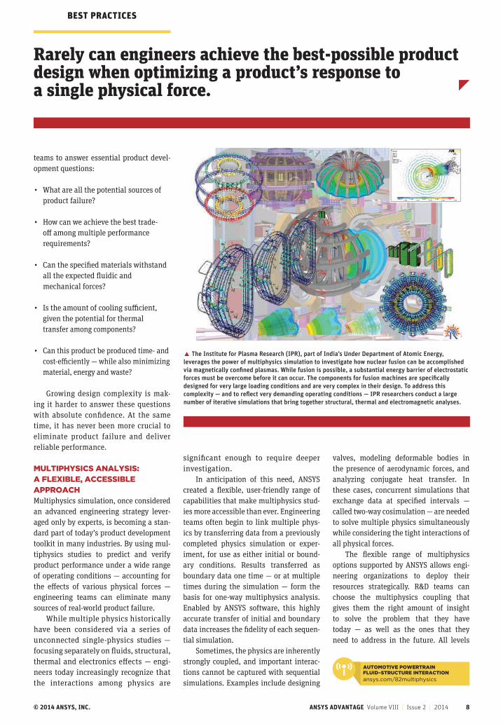
� The Institute for Plasma Research (IPR), part of India’s Under Department of Atomic Energy, leverages the power of multiphysics simulation to investigate how nuclear fusion can be accomplished via magnetically confined plasmas. While fusion is possible, a substantial energy barrier of electrostatic forces must be overcome before it can occur. The components for fusion machines are specifically designed for very large loading conditions and are very complex in their design. To address this complexity — and to reflect very demanding operating conditions — IPR researchers conduct a large number of iterative simulations that bring together structural, thermal and electromagnetic analyses.
significant enough to require deeper investigation.
In anticipation of this need, ANSYS created a flexible, user-friendly range of capabilities that make multiphysics stud-ies more accessible than ever. Engineering teams often begin to link multiple phys-ics by transferring data from a previously completed physics simulation or exper-iment, for use as either initial or bound-ary conditions. Results transferred as boundary data one time — or at multiple times during the simulation — form the basis for one-way multiphysics analysis. Enabled by ANSYS software, this highly accurate transfer of initial and boundary data increases the fidelity of each sequen-tial simulation.
Sometimes, the physics are inherently strongly coupled, and important interac-tions cannot be captured with sequential simulations. Examples include designing
valves, modeling deformable bodies in the presence of aerodynamic forces, and analyzing conjugate heat transfer. In these cases, concurrent simulations that exchange data at specified intervals — called two-way cosimulation — are needed to solve multiple physics simultaneously while considering the tight interactions of all physical forces.
The flexible range of multiphysics options supported by ANSYS allows engi-neering organizations to deploy their resources strategically. R&D teams can choose the multiphysics coupling that gives them the right amount of insight to solve the problem that they have today — as well as the ones that they need to address in the future. All levels
Rarely can engineers achieve the best-possible product design when optimizing a product’s response to a single physical force.
BEST PRACTICES
AUTOMOTIVE POWERTRAIN FLUID–STRUCTURE INTERACTION
ansys.com/82multiphysics
© 2014 ANSYS, INC. ANSYS ADVANTAGE Volume VIII | Issue 2 | 2014 9
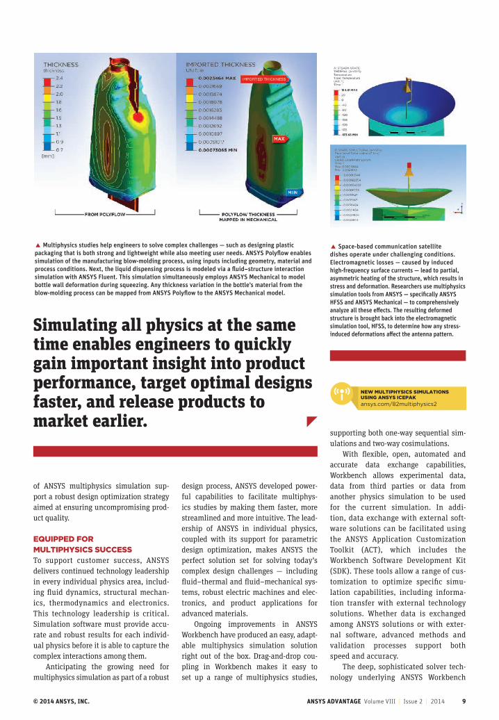
� Space-based communication satellite dishes operate under challenging conditions. Electromagnetic losses — caused by induced high-frequency surface currents — lead to partial, asymmetric heating of the structure, which results in stress and deformation. Researchers use multiphysics simulation tools from ANSYS — specifically ANSYS HFSS and ANSYS Mechanical — to comprehensively analyze all these effects. The resulting deformed structure is brought back into the electromagnetic simulation tool, HFSS, to determine how any stress-induced deformations affect the antenna pattern.
� Multiphysics studies help engineers to solve complex challenges — such as designing plastic packaging that is both strong and lightweight while also meeting user needs. ANSYS Polyflow enables simulation of the manufacturing blow-molding process, using inputs including geometry, material and process conditions. Next, the liquid dispensing process is modeled via a fluid–structure interaction simulation with ANSYS Fluent. This simulation simultaneously employs ANSYS Mechanical to model bottle wall deformation during squeezing. Any thickness variation in the bottle’s material from the blow-molding process can be mapped from ANSYS Polyflow to the ANSYS Mechanical model.
Simulating all physics at the same time enables engineers to quickly gain important insight into product performance, target optimal designs faster, and release products to market earlier.
of ANSYS multiphysics simulation sup-port a robust design optimization strategy aimed at ensuring uncompromising prod-uct quality.
EQUIPPED FOR MULTIPHYSICS SUCCESSTo support customer success, ANSYS delivers continued technology leadership in every individual physics area, includ-ing fluid dynamics, structural mechan-ics, thermodynamics and electronics. This technology leadership is critical. Simulation software must provide accu-rate and robust results for each individ-ual physics before it is able to capture the complex interactions among them.
Anticipating the growing need for multiphysics simulation as part of a robust
design process, ANSYS developed power-ful capabilities to facilitate multiphys-ics studies by making them faster, more streamlined and more intuitive. The lead-ership of ANSYS in individual physics, coupled with its support for parametric design optimization, makes ANSYS the perfect solution set for solving today’s complex design challenges — including fluid–thermal and fluid–mechanical sys-tems, robust electric machines and elec-tronics, and product applications for advanced materials.
Ongoing improvements in ANSYS Workbench have produced an easy, adapt-able multiphysics simulation solution right out of the box. Drag-and-drop cou-pling in Workbench makes it easy to set up a range of multiphysics studies,
supporting both one-way sequential sim-ulations and two-way cosimulations.
With flexible, open, automated and accurate data exchange capabilities, Workbench allows experimental data, data from third parties or data from another physics simulation to be used for the current simulation. In addi-tion, data exchange with external soft-ware solutions can be facilitated using the ANSYS Application Customization Toolkit (ACT), which includes the Workbench Software Development Kit (SDK). These tools allow a range of cus-tomization to optimize specific simu-lation capabilities, including informa-tion transfer with external technology solutions. Whether data is exchanged among ANSYS solutions or with exter-nal software, advanced methods and validation processes support both speed and accuracy.
The deep, sophisticated solver tech-nology underlying ANSYS Workbench
NEW MULTIPHYSICS SIMULATIONS USING ANSYS ICEPAK
ansys.com/82multiphysics2
© 2014 ANSYS, INC. ANSYS ADVANTAGE Volume VIII | Issue 2 | 2014 10
can zero in on optimal designs faster, while deeply investigating the interactions of all relevant physics via multiphysics analysis.
ANSYS Engineering Knowledge Manager (EKM) helps product development teams manage the large scale and scope of infor-mation that is generated by multiphysics studies. ANSYS EKM addresses the many critical activities associated with manag-ing simulation data, including backup and archival, traceability and auditing, process automation, collaboration and capture of engineering expertise, and intellectual property protection.
In addition, reduced-order modeling (ROM) methods from ANSYS can trans-form a series of complex multiphysics sim-ulations into 0-D or 1-D models that rep-resent the dynamics of the multiphysics simulation in a systems-level analysis — while avoiding the high costs associated with rerunning simulations for each oper-ating point. Whether product development teams require the extreme high fidelity of 3-D modeling or the broad view and rapid results of lower-order simulation, ANSYS offers an unmatched level of scalability.
BE INSPIRED BY THE BEST IN CLASSIf conducting multiphysics simula-tions seems out of reach for your own engineering team, this issue of ANSYS Advantage should serve as a power-ful inspiration. The following pages show firsthand how engineers in every
includes high-performance computing (HPC) capabilities and parallel scalabil-ity that accelerate the solution of numer-ically large multiphysics simulations. Industry-leading ANSYS solver technol-ogy can easily accommodate large geom-etries with high mesh counts as well as the enormous amount of data generated during detailed multiphysics analyses. Workbench manages the complex inter-action between physics solvers during cosimulation.
A COMPREHENSIVE ANSWER TO TODAY’S SIMULATION CHALLENGESIn addition to providing these founda-tional capabilities, ANSYS offers an array of simulation platform services that help product development teams to support robust design optimization via multiphys-ics simulations.
ANSYS DesignXplorer enables engi-neers to explore, understand and optimize their designs via parametric analysis. They
BEST PRACTICES
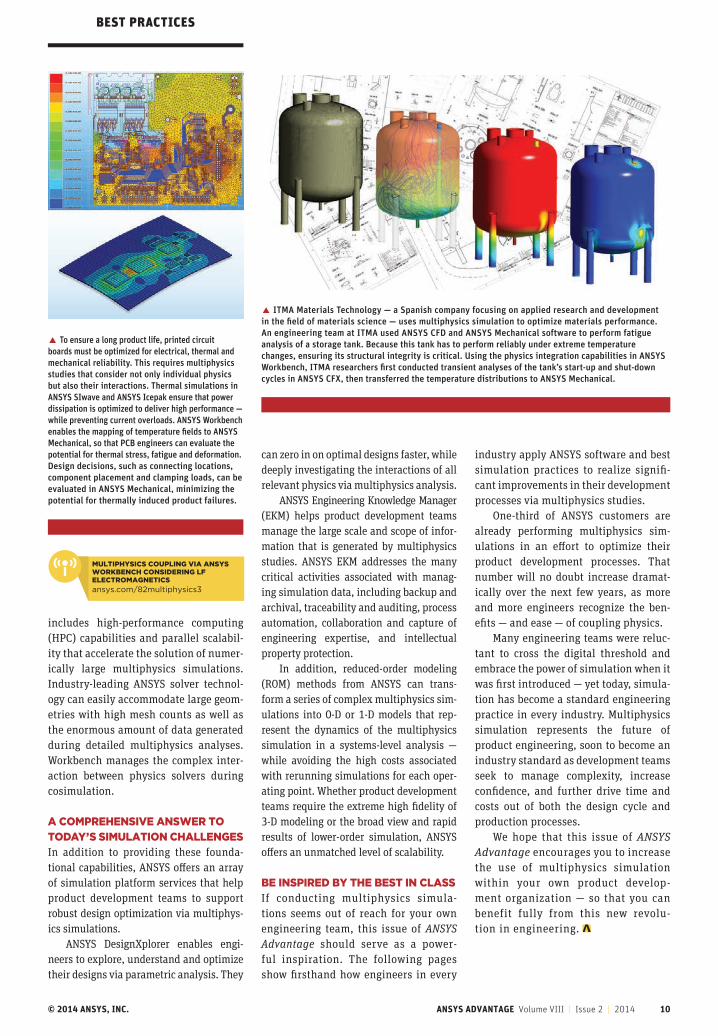
� ITMA Materials Technology — a Spanish company focusing on applied research and development in the field of materials science — uses multiphysics simulation to optimize materials performance. An engineering team at ITMA used ANSYS CFD and ANSYS Mechanical software to perform fatigue analysis of a storage tank. Because this tank has to perform reliably under extreme temperature changes, ensuring its structural integrity is critical. Using the physics integration capabilities in ANSYS Workbench, ITMA researchers first conducted transient analyses of the tank’s start-up and shut-down cycles in ANSYS CFX, then transferred the temperature distributions to ANSYS Mechanical.
� To ensure a long product life, printed circuit boards must be optimized for electrical, thermal and mechanical reliability. This requires multiphysics studies that consider not only individual physics but also their interactions. Thermal simulations in ANSYS SIwave and ANSYS Icepak ensure that power dissipation is optimized to deliver high performance — while preventing current overloads. ANSYS Workbench enables the mapping of temperature fields to ANSYS Mechanical, so that PCB engineers can evaluate the potential for thermal stress, fatigue and deformation. Design decisions, such as connecting locations, component placement and clamping loads, can be evaluated in ANSYS Mechanical, minimizing the potential for thermally induced product failures.
MULTIPHYSICS COUPLING VIA ANSYS WORKBENCH CONSIDERING LF ELECTROMAGNETICS
ansys.com/82multiphysics3
industry apply ANSYS software and best simulation practices to realize signifi-cant improvements in their development processes via multiphysics studies.
One-third of ANSYS customers are already performing multiphysics sim-ulations in an effort to optimize their product development processes. That number will no doubt increase dramat-ically over the next few years, as more and more engineers recognize the ben-efits — and ease — of coupling physics.
Many engineering teams were reluc-tant to cross the digital threshold and embrace the power of simulation when it was first introduced — yet today, simula-tion has become a standard engineering practice in every industry. Multiphysics simulation represents the future of product engineering, soon to become an industry standard as development teams seek to manage complexity, increase confidence, and further drive time and costs out of both the design cycle and production processes.
We hope that this issue of ANSYS Advantage encourages you to increase the use of multiphysics simulation within your own product develop-ment organization — so that you can benefit fully from this new revolu-tion in engineering.

© 2014 ANSYS, INC. ANSYS ADVANTAGE Volume VIII | Issue 1 | 2014 11
ROBUST ELECTRIC MACHINE DESIGN THROUGH MULTIPHYSICS
By Cassiano A. Cezario, Briam C. Bork, Marcelo Verardi, Research and Technological Innovation Department, and José R. Santos, Product Development and Application Department, WEG Equipamentos Elétricos S.A. — Motores, Jaraguá do Sul, Brazil
Electromagnetic, mechanical and thermal simulation plus design optimization help to improve energy efficiency, noise and bearing life of robust electric motors.
ROBUST ELECTRIC MACHINE DESIGN
© 2014 ANSYS, INC. ANSYS ADVANTAGE Volume VIII | Issue 2 | 2014 12
WEG engineers used a wide range of ANSYS tools to deliver optimal energy efficiency, low operating noise and long bearing life on its new line of electric motors.
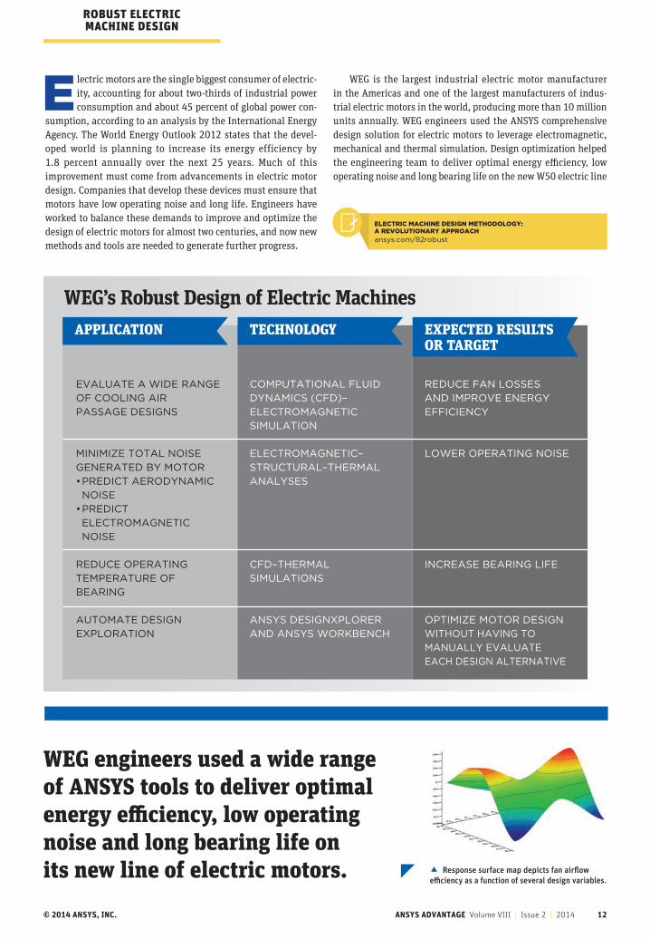
WEG’s Robust Design of Electric Machines
Electric motors are the single biggest consumer of electric-ity, accounting for about two-thirds of industrial power consumption and about 45 percent of global power con-
sumption, according to an analysis by the International Energy Agency. The World Energy Outlook 2012 states that the devel-oped world is planning to increase its energy efficiency by 1.8 percent annually over the next 25 years. Much of this improvement must come from advancements in electric motor design. Companies that develop these devices must ensure that motors have low operating noise and long life. Engineers have worked to balance these demands to improve and optimize the design of electric motors for almost two centuries, and now new methods and tools are needed to generate further progress.
WEG is the largest industrial electric motor manufacturer in the Americas and one of the largest manufacturers of indus-trial electric motors in the world, producing more than 10 million units annually. WEG engineers used the ANSYS comprehensive design solution for electric motors to leverage electromagnetic, mechanical and thermal simulation. Design optimization helped the engineering team to deliver optimal energy efficiency, low operating noise and long bearing life on the new W50 electric line
EVALUATE A WIDE RANGE
OF COOLING AIR
PASSAGE DESIGNS
MINIMIZE TOTAL NOISE
GENERATED BY MOTOR
• PREDICT AERODYNAMIC
NOISE
• PREDICT
ELECTROMAGNETIC
NOISE
REDUCE OPERATING
TEMPERATURE OF
BEARING
AUTOMATE DESIGN
EXPLORATION
COMPUTATIONAL FLUID
DYNAMICS (CFD)–
ELECTROMAGNETIC
SIMULATION
ELECTROMAGNETIC–
STRUCTURAL–THERMAL
ANALYSES
CFD–THERMAL
SIMULATIONS
ANSYS DESIGNXPLORER
AND ANSYS WORKBENCH
REDUCE FAN LOSSES
AND IMPROVE ENERGY
EFFICIENCY
LOWER OPERATING NOISE
INCREASE BEARING LIFE
OPTIMIZE MOTOR DESIGN
WITHOUT HAVING TO
MANUALLY EVALUATE
EACH DESIGN ALTERNATIVE
APPLICATION TECHNOLOGY EXPECTED RESULTS OR TARGET
ROBUST ELECTRIC MACHINE DESIGN
� Response surface map depicts fan airflow efficiency as a function of several design variables.
ELECTRIC MACHINE DESIGN METHODOLOGY: A REVOLUTIONARY APPROACH
ansys.com/82robust
© 2014 ANSYS, INC. ANSYS ADVANTAGE Volume VIII | Issue 2 | 2014 13
of motors. The broad range of ANSYS capa-bilities was instrumental in designing and optimizing the electric motor with-out the need to individually evaluate each design alternative.
IMPROVING ENERGY EFFICIENCYLarge electric motors in the 125 horse-power to 1,750 horsepower range typ-ically have two fans: one to cool the motor interior and the other to cool its exterior. These fans consume a consid-erable amount of power, and WEG engi-neers believed that a promising approach to improving energy efficiency was to improve fan efficiency. They focused on the internal fan, particularly on reducing losses as air flows through the motor. The airflow generated by the fan flows through openings in the frame. Losses could be reduced by increasing these openings — but this strategy would reduce the motor’s electromagnetic performance.
WEG engineers used ANSYS CFD soft-ware to model the airflow through the interior of the motor. They defined key parameters, such as the openings where air passes through the frame, as para-metric dimension variables. Since many of these design parameters impact the motor’s electromagnetic performance, engineers produced an ANSYS Maxwell electromagnetic model of the motor with the same parametric variables as the CFD model. They generated a table of varying values for each of the parameters.
WEG employed ANSYS DesignXplorer to create a design of experiments (DOE) that subdivided the design space to effi-ciently explore it with a relatively small number of simulation experiments and to run multiphysics simulations with-out human intervention. Comprehensive simulation tools in the ANSYS Workbench environment and design optimization with ANSYS DesignXplorer enabled WEG
to increase the number of simulations per-formed from four per month in 2005 to 800 per month currently. High-performance computing (HPC) also helped enable this improvement. WEG uses HPC Packs for CFD, and Maxwell runs with 64 cores dis-tributed across eight workstations.
Output results for each design point were stored in a table and visualized with a response surface map that com-pletely maps out the design space. The response surface was used to graphically plot the effect of variables on fan losses. Simulations were not coupled in this case due to computing resource limitations; however, in the future, WEG will use cou-pled multiphysics simulations to even more accurately determine optimal val-ues for parametric variables by consid-ering all of the physics. WEG engineers manually compared response surface maps, plots and tables for the CFD and electromagnetic analysis to determine the
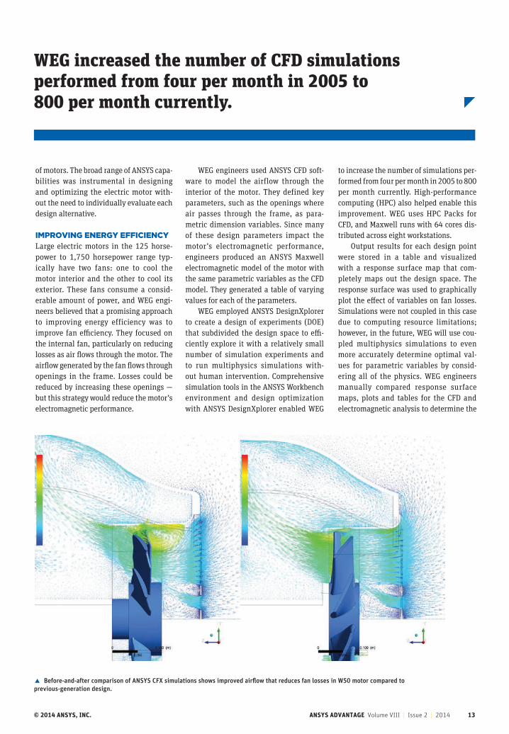
� Before-and-after comparison of ANSYS CFX simulations shows improved airflow that reduces fan losses in W50 motor compared to previous-generation design.
WEG increased the number of CFD simulations performed from four per month in 2005 to 800 per month currently.
© 2014 ANSYS, INC. ANSYS ADVANTAGE Volume VIII | Issue 2 | 2014 14
ROBUST ELECTRIC MACHINE DESIGN
ANSYS multiphysics tools help WEG deliver best-in-class performance for electric motors while substantially reducing the lead time and cost of the product development process.
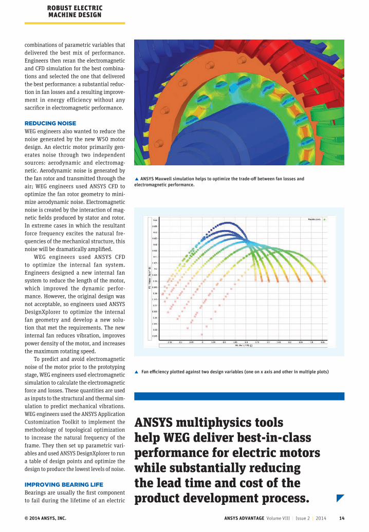
� ANSYS Maxwell simulation helps to optimize the trade-off between fan losses and electromagnetic performance.
� Fan efficiency plotted against two design variables (one on x axis and other in multiple plots)
combinations of parametric variables that delivered the best mix of performance. Engineers then reran the electromagnetic and CFD simulation for the best combina-tions and selected the one that delivered the best performance: a substantial reduc-tion in fan losses and a resulting improve-ment in energy efficiency without any sacrifice in electromagnetic performance.
REDUCING NOISEWEG engineers also wanted to reduce the noise generated by the new W50 motor design. An electric motor primarily gen-erates noise through two independent sources: aerodynamic and electromag-netic. Aerodynamic noise is generated by the fan rotor and transmitted through the air; WEG engineers used ANSYS CFD to optimize the fan rotor geometry to mini-mize aerodynamic noise. Electromagnetic noise is created by the interaction of mag-netic fields produced by stator and rotor. In extreme cases in which the resultant force frequency excites the natural fre-quencies of the mechanical structure, this noise will be dramatically amplified.
WEG engineers used ANSYS CFD to optimize the internal fan system. Engineers designed a new internal fan system to reduce the length of the motor, which improved the dynamic perfor-mance. However, the original design was not acceptable, so engineers used ANSYS DesignXplorer to optimize the internal fan geometry and develop a new solu-tion that met the requirements. The new internal fan reduces vibration, improves power density of the motor, and increases the maximum rotating speed.
To predict and avoid electromagnetic noise of the motor prior to the prototyping stage, WEG engineers used electromagnetic simulation to calculate the electromagnetic force and losses. These quantities are used as inputs to the structural and thermal sim-ulation to predict mechanical vibrations. WEG engineers used the ANSYS Application Customization Toolkit to implement the methodology of topological optimization to increase the natural frequency of the frame. They then set up parametric vari-ables and used ANSYS DesignXplorer to run a table of design points and optimize the design to produce the lowest levels of noise.
IMPROVING BEARING LIFEBearings are usually the first component to fail during the lifetime of an electric
© 2014 ANSYS, INC. ANSYS ADVANTAGE Volume VIII | Issue 2 | 2014 15
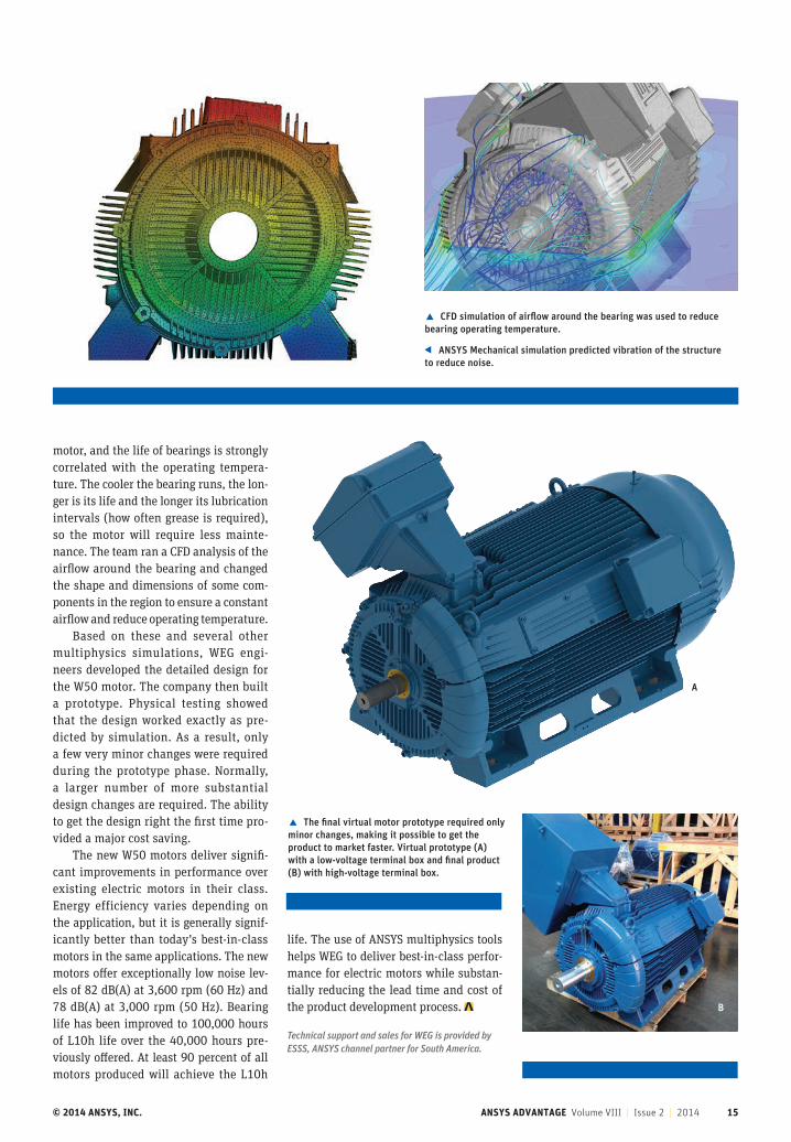
� CFD simulation of airflow around the bearing was used to reduce bearing operating temperature.
ANSYS Mechanical simulation predicted vibration of the structure to reduce noise.
motor, and the life of bearings is strongly correlated with the operating tempera-ture. The cooler the bearing runs, the lon-ger is its life and the longer its lubrication intervals (how often grease is required), so the motor will require less mainte-nance. The team ran a CFD analysis of the airflow around the bearing and changed the shape and dimensions of some com-ponents in the region to ensure a constant airflow and reduce operating temperature.
Based on these and several other multiphysics simulations, WEG engi-neers developed the detailed design for the W50 motor. The company then built a prototype. Physical testing showed that the design worked exactly as pre-dicted by simulation. As a result, only a few very minor changes were required during the prototype phase. Normally, a larger number of more substantial design changes are required. The ability to get the design right the first time pro-vided a major cost saving.
The new W50 motors deliver signifi-cant improvements in performance over existing electric motors in their class. Energy efficiency varies depending on the application, but it is generally signif-icantly better than today’s best-in-class motors in the same applications. The new motors offer exceptionally low noise lev-els of 82 dB(A) at 3,600 rpm (60 Hz) and 78 dB(A) at 3,000 rpm (50 Hz). Bearing life has been improved to 100,000 hours of L10h life over the 40,000 hours pre-viously offered. At least 90 percent of all motors produced will achieve the L10h
life. The use of ANSYS multiphysics tools helps WEG to deliver best-in-class perfor-mance for electric motors while substan-tially reducing the lead time and cost of the product development process.
Technical support and sales for WEG is provided by ESSS, ANSYS channel partner for South America.
� The final virtual motor prototype required only minor changes, making it possible to get the product to market faster. Virtual prototype (A) with a low-voltage terminal box and final product (B) with high-voltage terminal box.
A
B
© 2014 ANSYS, INC. ANSYS ADVANTAGE Volume VIII | Issue 2 | 2014 16
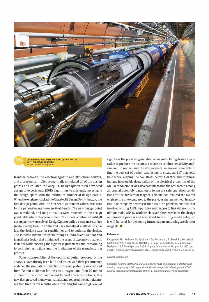
N ew magnets for the Large Hadron Collider (LHC) at the European Organization for
Nuclear Research (CERN) have to be smaller than the magnets they replace. The new sizing allows room for addi-tional instruments, yet the magnets must generate a higher magnetic field than the components they replace. These new magnets generate axial forces of up to 84 metric tonnes per side on the endplates and 3.16 MN/m lateral forces per quadrant at the nominal current of 11.85 kA, which is very impressive as it is almost double the existing main dipoles on the LHC. The structure must maintain near-zero deformation of the conductor to avoid generating quenches (transition of the conductor from the superconducting to the resistive state) in the coils. Even a small deformation could increase the electrical resistance
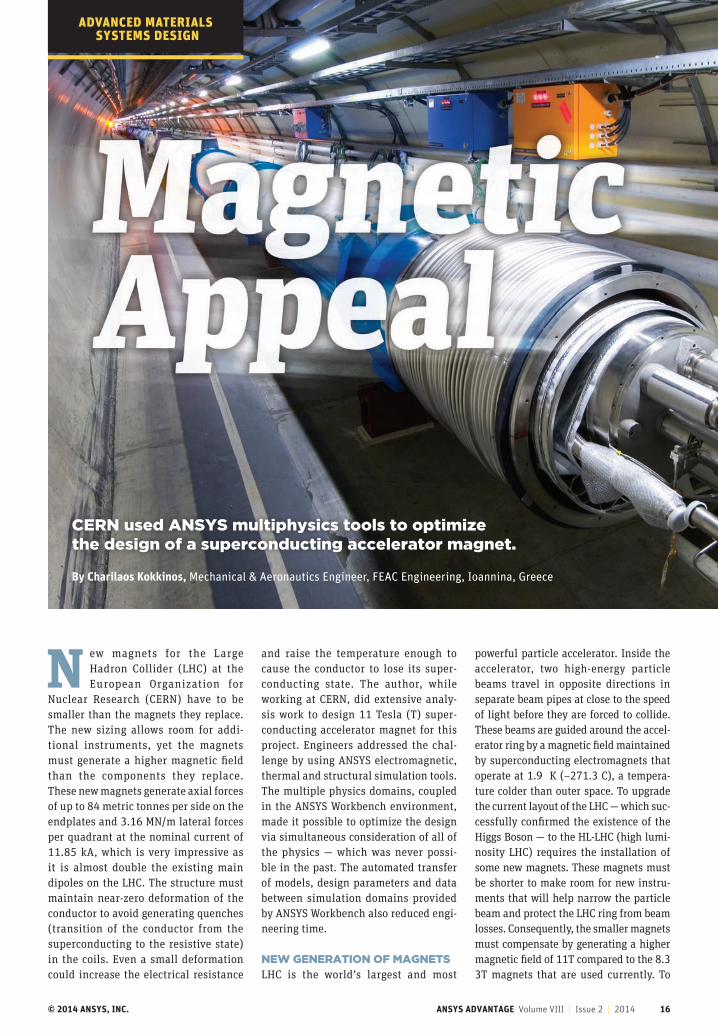
By Charilaos Kokkinos, Mechanical & Aeronautics Engineer, FEAC Engineering, Ioannina, Greece
CERN used ANSYS multiphysics tools to optimize the design of a superconducting accelerator magnet.
and raise the temperature enough to cause the conductor to lose its super-conducting state. The author, while working at CERN, did extensive analy-sis work to design 11 Tesla (T) super-conducting accelerator magnet for this project. Engineers addressed the chal-lenge by using ANSYS electromagnetic, thermal and structural simulation tools. The multiple physics domains, coupled in the ANSYS Workbench environment, made it possible to optimize the design via simultaneous consideration of all of the physics — which was never possi-ble in the past. The automated transfer of models, design parameters and data between simulation domains provided by ANSYS Workbench also reduced engi-neering time.
NEW GENERATION OF MAGNETSLHC is the world’s largest and most
powerful particle accelerator. Inside the accelerator, two high-energy particle beams travel in opposite directions in separate beam pipes at close to the speed of light before they are forced to collide. These beams are guided around the accel-erator ring by a magnetic field maintained by superconducting electromagnets that operate at 1.9 K (–271.3 C), a tempera-ture colder than outer space. To upgrade the current layout of the LHC — which suc-cessfully confirmed the existence of the Higgs Boson — to the HL-LHC (high lumi-nosity LHC) requires the installation of some new magnets. These magnets must be shorter to make room for new instru-ments that will help narrow the particle beam and protect the LHC ring from beam losses. Consequently, the smaller magnets must compensate by generating a higher magnetic field of 11T compared to the 8.3 3T magnets that are used currently. To
ADVANCED MATERIALS SYSTEMS DESIGN
© 2014 ANSYS, INC. ANSYS ADVANTAGE Volume VIII | Issue 2 | 2014 17
increase the magnetic field, the conductor had to be changed from Nb-Ti to Nb3Sn.
The magnets needed to be extremely rigid, because even a slight movement of the conductor (within the order of nano-meters) could initiate quenches. A small deformation of the conductor can increase its electrical resistance locally, leading to a rise of the temperature at that point and the loss of the superconducting state. On the other hand, the structural design can take advantage of how the magnet’s low operating temperature increases the stiff-ness of the materials and subsequently the rigidity of the structure. The correct combination of applied pre-stress at room temperature along with the additional stress from the shrinkage of the structure during the cool-down will allow the coil to perform within safe stress limits. Clearly, the coupled electromagnetic, structural and thermal properties of each proposed
©CE
RN
Engineers addressed the challenge of designing new magnets for CERN by using ANSYS electromagnetic, thermal and structural simulation tools.
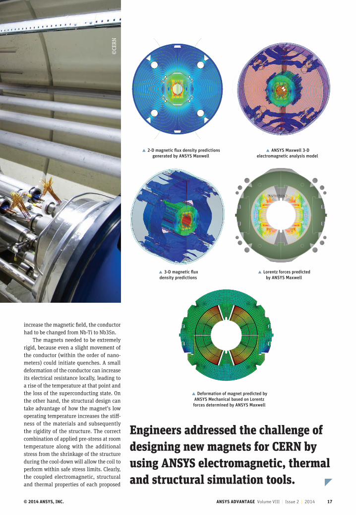
� 2-D magnetic flux density predictions generated by ANSYS Maxwell
� ANSYS Maxwell 3-D electromagnetic analysis model
� 3-D magnetic flux density predictions
� Lorentz forces predicted by ANSYS Maxwell
� Deformation of magnet predicted by ANSYS Mechanical based on Lorentz
forces determined by ANSYS Maxwell
© 2014 ANSYS, INC. ANSYS ADVANTAGE Volume VIII | Issue 2 | 2014 18
ADVANCED MATERIALS SYSTEMS DESIGN
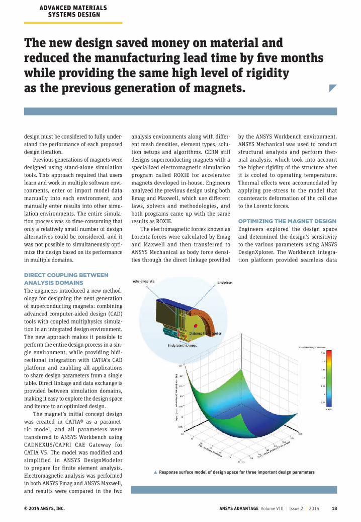
The new design saved money on material and reduced the manufacturing lead time by five months while providing the same high level of rigidity as the previous generation of magnets.
� Response surface model of design space for three important design parameters
design must be considered to fully under-stand the performance of each proposed design iteration.
Previous generations of magnets were designed using stand-alone simulation tools. This approach required that users learn and work in multiple software envi-ronments, enter or import model data manually into each environment, and manually enter results into other simu-lation environments. The entire simula-tion process was so time-consuming that only a relatively small number of design alternatives could be considered, and it was not possible to simultaneously opti-mize the design based on its performance in multiple domains.
DIRECT COUPLING BETWEEN ANALYSIS DOMAINSThe engineers introduced a new method-ology for designing the next generation of superconducting magnets: combining advanced computer-aided design (CAD) tools with coupled multiphysics simula-tion in an integrated design environment. The new approach makes it possible to perform the entire design process in a sin-gle environment, while providing bidi-rectional integration with CATIA’s CAD platform and enabling all applications to share design parameters from a single table. Direct linkage and data exchange is provided between simulation domains, making it easy to explore the design space and iterate to an optimized design.
The magnet’s initial concept design was created in CATIA® as a paramet-ric model, and all parameters were transferred to ANSYS Workbench using CADNEXUS/CAPRI CAE Gateway for CATIA V5. The model was modified and simplified in ANSYS DesignModeler to prepare for finite element analysis. Electromagnetic analysis was performed in both ANSYS Emag and ANSYS Maxwell, and results were compared in the two
analysis environments along with differ-ent mesh densities, element types, solu-tion setups and algorithms. CERN still designs superconducting magnets with a specialized electromagnetic simulation program called ROXIE for accelerator magnets developed in-house. Engineers analyzed the previous design using both Emag and Maxwell, which use different laws, solvers and methodologies, and both programs came up with the same results as ROXIE.
The electromagnetic forces known as Lorentz forces were calculated by Emag and Maxwell and then transferred to ANSYS Mechanical as body force densi-ties through the direct linkage provided
by the ANSYS Workbench environment. ANSYS Mechanical was used to conduct structural analysis and perform ther-mal analysis, which took into account the higher rigidity of the structure after it is cooled to operating temperature. Thermal effects were accommodated by applying pre-stress to the model that counteracts deformation of the coil due to the Lorentz forces.
OPTIMIZING THE MAGNET DESIGNEngineers explored the design space and determined the design’s sensitivity to the various parameters using ANSYS DesignXplorer. The Workbench integra-tion platform provided seamless data
© 2014 ANSYS, INC. ANSYS ADVANTAGE Volume VIII | Issue 2 | 2014 19
transfer between the electromagnetic and structural solvers, and a process controller sequentially simulated all of the design points and collated the outputs. DesignXplorer used advanced design of experiments (DOE) algorithms to efficiently investigate the design space with the minimum number of design points. When the engineer clicked the Update All Design Points button, the first design point, with the first set of parameter values, was sent to the parameter manager in Workbench. The new design point was simulated, and output results were returned to the design point table where they were stored. The process continued until all design points were solved. DesignXplorer builds a response surface (meta model) from the data and uses statistical methods to ana-lyze the design space for sensitivities and to optimize the design. The software automatically ran through hundreds of iterations and identified a design that minimized the usage of expensive magnetic material while meeting the rigidity requirements and conforming to both size restrictions and the limitations of the manufacturing process.
Some subassemblies of the optimized design proposed by the analysis have already been built and tested, and their performance matched the simulation predictions. The end plate size was reduced from 70 mm to 50 mm for the 1-in-1 magnet and from 90 mm to 75 mm for the 2-in-1 component to meet space restrictions; this new design saved money on material and reduced the manufactur-ing lead time by five months while providing the same high level of
©CE
RN
UNDERSTAND AND IMPROVE YOUR DESIGN FASTER WITH ELECTROMAGNETICSansys.com/82magnetic
rigidity as the previous generation of magnets. Using design explo-ration to produce the response surface, to conduct sensitivity anal-ysis and to understand the design space, engineers were able to find the best set of design parameters to create an 11T magnetic field while keeping the coil stress below 150 MPa and minimiz-ing any irreversible degradation of the electrical properties of the Nb3Sn conductor. It was also possible to find the best match among all crucial assembly parameters to ensure safe operation condi-tions for the accelerator magnet. This method reduced the overall engineering time compared to the previous design method. In addi-tion, the company decreased time over the previous method that involved writing APDL input files and macros to link different sim-ulation tools. ANSYS Workbench saved three weeks in the design optimization process and also saved time during model setup, so it will be used for designing future superconducting accelerator magnets.
References
Karppinen, M.; Andreev, N.; Apollinari, G.; Auchmann, B.; Barzi, E.; Bossert, R.; Kashikhin, V.V.; Nobrega, A.; Novitski, I.; Rossi, L.; Smekens, D.; Zlobin, A.V. Design of 11 T Twin-Aperture Nb3Sn Dipole Demonstrator Magnet for LHC Up-grades. Applied Superconductivity, IEEE Transactions. 2012. Volume 22, Issue 3.
www.feacomp.com
Charilaos Kokkinos left CERN in 2013 to found FEAC Engineering, a startup engi-neering company specializing in simulation-driven product development. FEAC warmly thanks the project leader of the 11T dipole magnet, Mikko Karppinen.

© 2014 ANSYS, INC. ANSYS ADVANTAGE Volume VIII | Issue 1 | 2014 20
EXHAUSTIVE SIMULATIONAn exhaust system designer uses multiphysics simulation to reduce
costly iterations by validating designs before testing.
By Matt Butson, Engineering Services Manager, and Ning Cao, Product Design Engineer, Active Exhaust Corp., Toronto, Canada
FLUID–THERMAL SYSTEMS DESIGN
© 2014 ANSYS, INC. ANSYS ADVANTAGE Volume VIII | Issue 2 | 2014 21
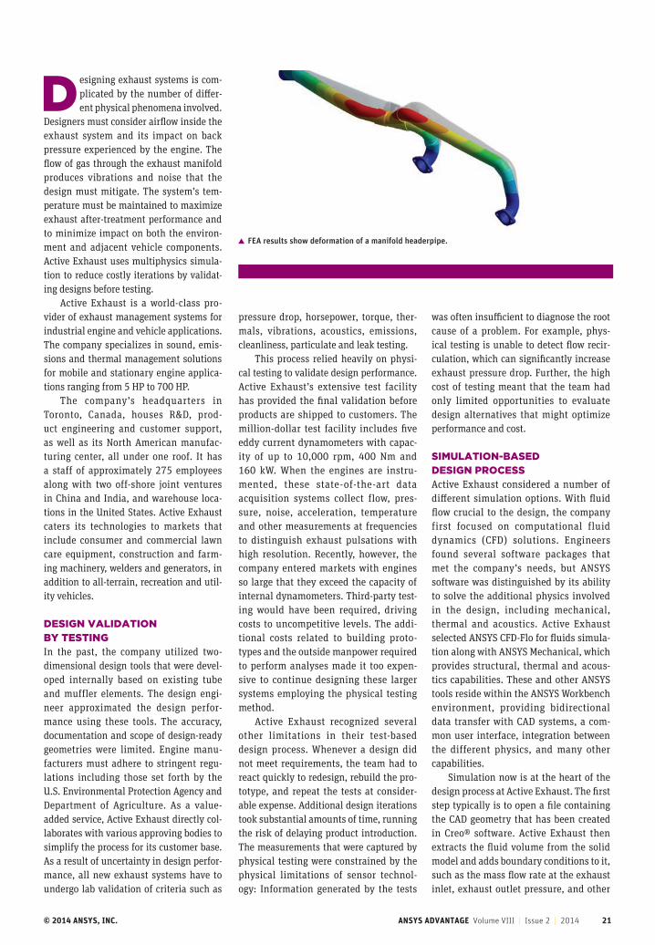
� FEA results show deformation of a manifold headerpipe.
Designing exhaust systems is com-plicated by the number of differ-ent physical phenomena involved.
Designers must consider airflow inside the exhaust system and its impact on back pressure experienced by the engine. The flow of gas through the exhaust manifold produces vibrations and noise that the design must mitigate. The system’s tem-perature must be maintained to maximize exhaust after-treatment performance and to minimize impact on both the environ-ment and adjacent vehicle components. Active Exhaust uses multiphysics simula-tion to reduce costly iterations by validat-ing designs before testing.
Active Exhaust is a world-class pro-vider of exhaust management systems for industrial engine and vehicle applications. The company specializes in sound, emis-sions and thermal management solutions for mobile and stationary engine applica-tions ranging from 5 HP to 700 HP.
The company’s headquarters in Toronto, Canada, houses R&D, prod-uct engineering and customer support, as well as its North American manufac-turing center, all under one roof. It has a staff of approximately 275 employees along with two off-shore joint ventures in China and India, and warehouse loca-tions in the United States. Active Exhaust caters its technologies to markets that include consumer and commercial lawn care equipment, construction and farm-ing machinery, welders and generators, in addition to all-terrain, recreation and util-ity vehicles.
DESIGN VALIDATION BY TESTINGIn the past, the company utilized two-dimensional design tools that were devel-oped internally based on existing tube and muffler elements. The design engi-neer approximated the design perfor-mance using these tools. The accuracy, documentation and scope of design-ready geometries were limited. Engine manu-facturers must adhere to stringent regu-lations including those set forth by the U.S. Environmental Protection Agency and Department of Agriculture. As a value-added service, Active Exhaust directly col-laborates with various approving bodies to simplify the process for its customer base. As a result of uncertainty in design perfor-mance, all new exhaust systems have to undergo lab validation of criteria such as
pressure drop, horsepower, torque, ther-mals, vibrations, acoustics, emissions, cleanliness, particulate and leak testing.
This process relied heavily on physi-cal testing to validate design performance. Active Exhaust’s extensive test facility has provided the final validation before products are shipped to customers. The million-dollar test facility includes five eddy current dynamometers with capac-ity of up to 10,000 rpm, 400 Nm and 160 kW. When the engines are instru-mented, these state-of-the-art data acquisition systems collect flow, pres-sure, noise, acceleration, temperature and other measurements at frequencies to distinguish exhaust pulsations with high resolution. Recently, however, the company entered markets with engines so large that they exceed the capacity of internal dynamometers. Third-party test-ing would have been required, driving costs to uncompetitive levels. The addi-tional costs related to building proto-types and the outside manpower required to perform analyses made it too expen-sive to continue designing these larger systems employing the physical testing method.
Active Exhaust recognized several other limitations in their test-based design process. Whenever a design did not meet requirements, the team had to react quickly to redesign, rebuild the pro-totype, and repeat the tests at consider-able expense. Additional design iterations took substantial amounts of time, running the risk of delaying product introduction. The measurements that were captured by physical testing were constrained by the physical limitations of sensor technol-ogy: Information generated by the tests
was often insufficient to diagnose the root cause of a problem. For example, phys-ical testing is unable to detect flow recir-culation, which can significantly increase exhaust pressure drop. Further, the high cost of testing meant that the team had only limited opportunities to evaluate design alternatives that might optimize performance and cost.
SIMULATION-BASED DESIGN PROCESSActive Exhaust considered a number of different simulation options. With fluid flow crucial to the design, the company first focused on computational fluid dynamics (CFD) solutions. Engineers found several software packages that met the company’s needs, but ANSYS software was distinguished by its ability to solve the additional physics involved in the design, including mechanical, thermal and acoustics. Active Exhaust selected ANSYS CFD-Flo for fluids simula-tion along with ANSYS Mechanical, which provides structural, thermal and acous-tics capabilities. These and other ANSYS tools reside within the ANSYS Workbench environment, providing bidirectional data transfer with CAD systems, a com-mon user interface, integration between the different physics, and many other capabilities.
Simulation now is at the heart of the design process at Active Exhaust. The first step typically is to open a file containing the CAD geometry that has been created in Creo® software. Active Exhaust then extracts the fluid volume from the solid model and adds boundary conditions to it, such as the mass flow rate at the exhaust inlet, exhaust outlet pressure, and other
© 2014 ANSYS, INC. ANSYS ADVANTAGE Volume VIII | Issue 2 | 2014 22
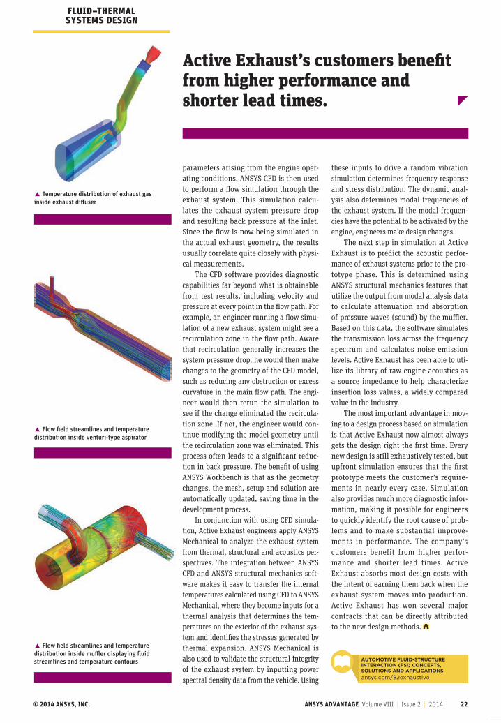
� Temperature distribution of exhaust gas inside exhaust diffuser
Active Exhaust’s customers benefit from higher performance and shorter lead times.
� Flow field streamlines and temperature distribution inside venturi-type aspirator
� Flow field streamlines and temperature distribution inside muffler displaying fluid streamlines and temperature contours AUTOMOTIVE FLUID-STRUCTURE
INTERACTION (FSI) CONCEPTS, SOLUTIONS AND APPLICATIONS
ansys.com/82exhaustive
FLUID–THERMAL SYSTEMS DESIGN
parameters arising from the engine oper-ating conditions. ANSYS CFD is then used to perform a flow simulation through the exhaust system. This simulation calcu-lates the exhaust system pressure drop and resulting back pressure at the inlet. Since the flow is now being simulated in the actual exhaust geometry, the results usually correlate quite closely with physi-cal measurements.
The CFD software provides diagnostic capabilities far beyond what is obtainable from test results, including velocity and pressure at every point in the flow path. For example, an engineer running a flow simu-lation of a new exhaust system might see a recirculation zone in the flow path. Aware that recirculation generally increases the system pressure drop, he would then make changes to the geometry of the CFD model, such as reducing any obstruction or excess curvature in the main flow path. The engi-neer would then rerun the simulation to see if the change eliminated the recircula-tion zone. If not, the engineer would con-tinue modifying the model geometry until the recirculation zone was eliminated. This process often leads to a significant reduc-tion in back pressure. The benefit of using ANSYS Workbench is that as the geometry changes, the mesh, setup and solution are automatically updated, saving time in the development process.
In conjunction with using CFD simula-tion, Active Exhaust engineers apply ANSYS Mechanical to analyze the exhaust system from thermal, structural and acoustics per-spectives. The integration between ANSYS CFD and ANSYS structural mechanics soft-ware makes it easy to transfer the internal temperatures calculated using CFD to ANSYS Mechanical, where they become inputs for a thermal analysis that determines the tem-peratures on the exterior of the exhaust sys-tem and identifies the stresses generated by thermal expansion. ANSYS Mechanical is also used to validate the structural integrity of the exhaust system by inputting power spectral density data from the vehicle. Using
these inputs to drive a random vibration simulation determines frequency response and stress distribution. The dynamic anal-ysis also determines modal frequencies of the exhaust system. If the modal frequen-cies have the potential to be activated by the engine, engineers make design changes.
The next step in simulation at Active Exhaust is to predict the acoustic perfor-mance of exhaust systems prior to the pro-totype phase. This is determined using ANSYS structural mechanics features that utilize the output from modal analysis data to calculate attenuation and absorption of pressure waves (sound) by the muffler. Based on this data, the software simulates the transmission loss across the frequency spectrum and calculates noise emission levels. Active Exhaust has been able to uti-lize its library of raw engine acoustics as a source impedance to help characterize insertion loss values, a widely compared value in the industry.
The most important advantage in mov-ing to a design process based on simulation is that Active Exhaust now almost always gets the design right the first time. Every new design is still exhaustively tested, but upfront simulation ensures that the first prototype meets the customer’s require-ments in nearly every case. Simulation also provides much more diagnostic infor-mation, making it possible for engineers to quickly identify the root cause of prob-lems and to make substantial improve-ments in performance. The company’s customers benefit from higher perfor-mance and shorter lead times. Active Exhaust absorbs most design costs with the intent of earning them back when the exhaust system moves into production. Active Exhaust has won several major contracts that can be directly attributed to the new design methods.
Simulation-based design is changing the way companies prototype – Intel and ANSYS are driving those innovations. Design simulation demands a professional-grade workstation. Intel® Xeon™ processor-based workstations give you the mega-tasking performance you need to instill design confidence, reduce product development cycles, and ultimately increase your manufacturing flexibility.
Our highest-performing design for mega-tasking.The Intel® Xeon® processor E5-2600 product family-based expert workstation moves data faster for processor-intensive simulation, rendering, and ray tracing tasks.
Tackle your toughest ANSYS simulation tasks with the pure performance of Intel Xeon processors. Discover the difference of Intel Xeon processors at www.ansys.com/DiscoverIntelXeon
Copyright © 2014 Intel Corporation. All rights reserved. Intel, the Intel logo, Xeon,and Xeon inside are trademarks of Intel Corporation in the U.S. and other countries.
*Other names and brands may be claimed as the property of others.
Robust Simulations Demand Robust Processors.
© 2014 ANSYS, INC. ANSYS ADVANTAGE Volume VIII | Issue 1 | 2014 23
Simulation-based design is changing the way companies prototype – Intel and ANSYS are driving those innovations. Design simulation demands a professional-grade workstation. Intel® Xeon™ processor-based workstations give you the mega-tasking performance you need to instill design confidence, reduce product development cycles, and ultimately increase your manufacturing flexibility.
Our highest-performing design for mega-tasking.The Intel® Xeon® processor E5-2600 product family-based expert workstation moves data faster for processor-intensive simulation, rendering, and ray tracing tasks.
Tackle your toughest ANSYS simulation tasks with the pure performance of Intel Xeon processors. Discover the difference of Intel Xeon processors at www.ansys.com/DiscoverIntelXeon
Copyright © 2014 Intel Corporation. All rights reserved. Intel, the Intel logo, Xeon, and Xeon inside are trademarks of Intel Corporation in the U.S. and other countries.
*Other names and brands may be claimed as the property of others.
Robust Simulations Demand Robust Processors.

© 2014 ANSYS, INC. ANSYS ADVANTAGE Volume VIII | Issue 1 | 2014 24
A new heart valve replacement procedure modeled
with multiphysics simulation could eliminate the need
for open-heart surgery.
A ortic valve stenosis, a narrowing of the aortic valve, is the most common type of heart valve disease. It affects about 2 percent of adults aged 65 or older. Symptoms of this chronic progressive disease include chest pain,
difficulty breathing, and fainting; in some cases, congestive heart failure can occur if the valve is not replaced.
Surgical aortic valve replacement, which involves open-heart surgery with a heart–lung machine, has been the definitive treatment for aortic valve stenosis for over 40 years. The surgical team replaces the aortic valve with either a mechanical valve or a tis-sue valve taken from a human donor or animal. The operative mortality of aortic valve replacement in low-risk patients younger than 70 years is around 2 percent. Long-term survival following aortic valve replacement is similar to that of patients of similar age who do not have the condition.
By Joël Grognuz, Team Leader Multiphysics, CADFEM, Renens, Switzerland
The number of elderly patients with aortic valve stenosis is increasing. These patients are often high-risk candidates for traditional aortic valve replacement. A recent study reported an operative mortality rate of 24 percent for patients 90 years and older after open-heart sur-gery — so there is a need for a less-inva-sive aortic valve replacement technique. Transcatheter aortic valve replacement (TAVR) (also called transcatheter aortic valve implantation or TAVI) is a relatively
FLUID–MECHANICAL SYSTEMS DESIGN
© 2014 ANSYS, INC. ANSYS ADVANTAGE Volume VIII | Issue 2 | 2014 25
Manufacturers of stents are simulating the process of implanting a stent and valve to better understand the method and estimate the forces.
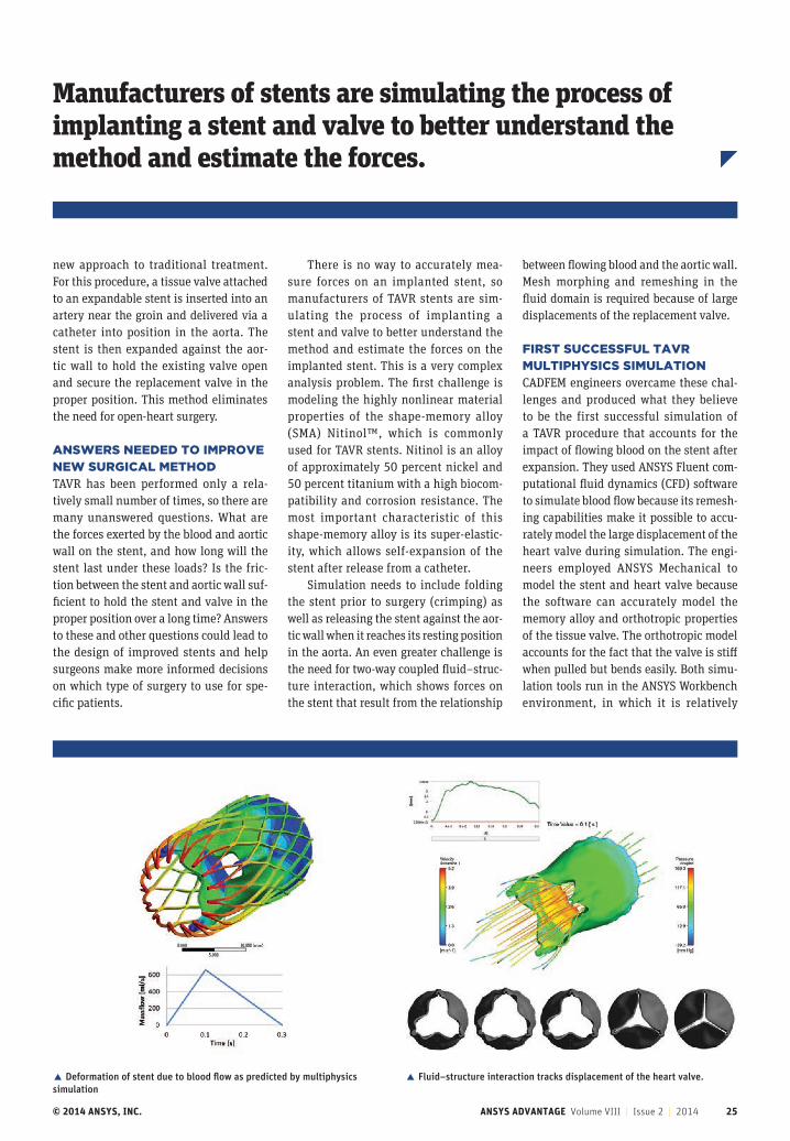
new approach to traditional treatment. For this procedure, a tissue valve attached to an expandable stent is inserted into an artery near the groin and delivered via a catheter into position in the aorta. The stent is then expanded against the aor-tic wall to hold the existing valve open and secure the replacement valve in the proper position. This method eliminates the need for open-heart surgery.
ANSWERS NEEDED TO IMPROVE NEW SURGICAL METHODTAVR has been performed only a rela-tively small number of times, so there are many unanswered questions. What are the forces exerted by the blood and aortic wall on the stent, and how long will the stent last under these loads? Is the fric-tion between the stent and aortic wall suf-ficient to hold the stent and valve in the proper position over a long time? Answers to these and other questions could lead to the design of improved stents and help surgeons make more informed decisions on which type of surgery to use for spe-cific patients.
There is no way to accurately mea-sure forces on an implanted stent, so manufacturers of TAVR stents are sim-ulating the process of implanting a stent and valve to better understand the method and estimate the forces on the implanted stent. This is a very complex analysis problem. The first challenge is modeling the highly nonlinear material properties of the shape-memory alloy (SMA) Nitinol™, which is commonly used for TAVR stents. Nitinol is an alloy of approximately 50 percent nickel and 50 percent titanium with a high biocom-patibility and corrosion resistance. The most important characteristic of this shape-memory alloy is its super-elastic-ity, which allows self-expansion of the stent after release from a catheter.
Simulation needs to include folding the stent prior to surgery (crimping) as well as releasing the stent against the aor-tic wall when it reaches its resting position in the aorta. An even greater challenge is the need for two-way coupled fluid–struc-ture interaction, which shows forces on the stent that result from the relationship
between flowing blood and the aortic wall. Mesh morphing and remeshing in the fluid domain is required because of large displacements of the replacement valve.
FIRST SUCCESSFUL TAVR MULTIPHYSICS SIMULATION CADFEM engineers overcame these chal-lenges and produced what they believe to be the first successful simulation of a TAVR procedure that accounts for the impact of flowing blood on the stent after expansion. They used ANSYS Fluent com-putational fluid dynamics (CFD) software to simulate blood flow because its remesh-ing capabilities make it possible to accu-rately model the large displacement of the heart valve during simulation. The engi-neers employed ANSYS Mechanical to model the stent and heart valve because the software can accurately model the memory alloy and orthotropic properties of the tissue valve. The orthotropic model accounts for the fact that the valve is stiff when pulled but bends easily. Both simu-lation tools run in the ANSYS Workbench environment, in which it is relatively
� Deformation of stent due to blood flow as predicted by multiphysics simulation
� Fluid–structure interaction tracks displacement of the heart valve.
© 2014 ANSYS, INC. ANSYS ADVANTAGE Volume VIII | Issue 2 | 2014 26
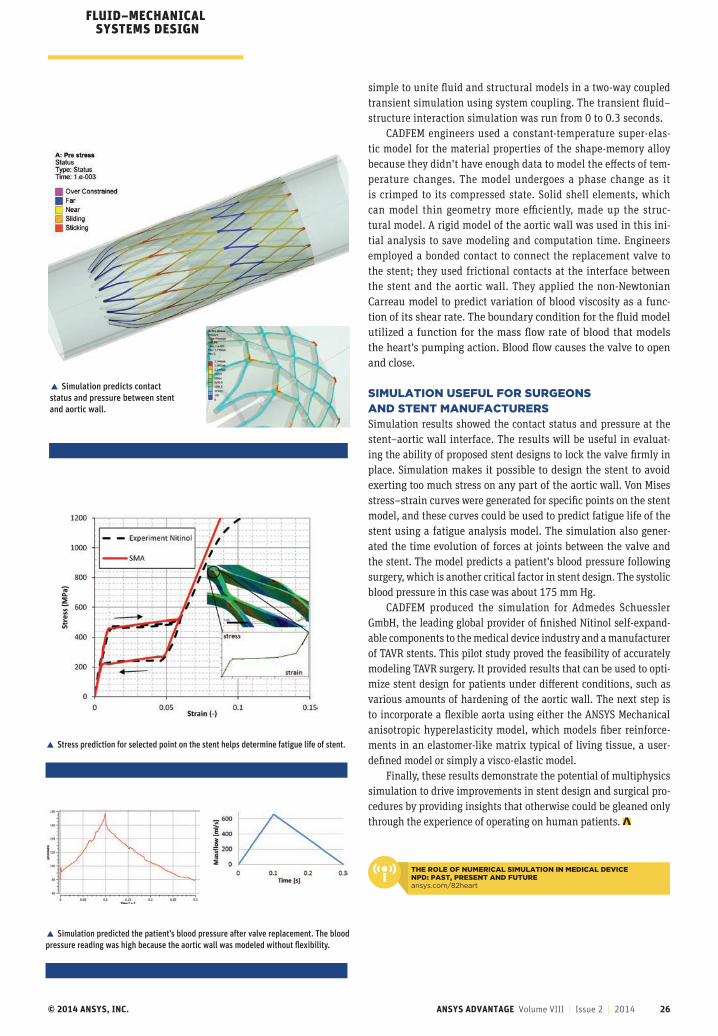
simple to unite fluid and structural models in a two-way coupled transient simulation using system coupling. The transient fluid–structure interaction simulation was run from 0 to 0.3 seconds.
CADFEM engineers used a constant-temperature super-elas-tic model for the material properties of the shape-memory alloy because they didn’t have enough data to model the effects of tem-perature changes. The model undergoes a phase change as it is crimped to its compressed state. Solid shell elements, which can model thin geometry more efficiently, made up the struc-tural model. A rigid model of the aortic wall was used in this ini-tial analysis to save modeling and computation time. Engineers employed a bonded contact to connect the replacement valve to the stent; they used frictional contacts at the interface between the stent and the aortic wall. They applied the non-Newtonian Carreau model to predict variation of blood viscosity as a func-tion of its shear rate. The boundary condition for the fluid model utilized a function for the mass flow rate of blood that models the heart’s pumping action. Blood flow causes the valve to open and close.
SIMULATION USEFUL FOR SURGEONS AND STENT MANUFACTURERSSimulation results showed the contact status and pressure at the stent–aortic wall interface. The results will be useful in evaluat-ing the ability of proposed stent designs to lock the valve firmly in place. Simulation makes it possible to design the stent to avoid exerting too much stress on any part of the aortic wall. Von Mises stress–strain curves were generated for specific points on the stent model, and these curves could be used to predict fatigue life of the stent using a fatigue analysis model. The simulation also gener-ated the time evolution of forces at joints between the valve and the stent. The model predicts a patient’s blood pressure following surgery, which is another critical factor in stent design. The systolic blood pressure in this case was about 175 mm Hg.
CADFEM produced the simulation for Admedes Schuessler GmbH, the leading global provider of finished Nitinol self-expand-able components to the medical device industry and a manufacturer of TAVR stents. This pilot study proved the feasibility of accurately modeling TAVR surgery. It provided results that can be used to opti-mize stent design for patients under different conditions, such as various amounts of hardening of the aortic wall. The next step is to incorporate a flexible aorta using either the ANSYS Mechanical anisotropic hyperelasticity model, which models fiber reinforce-ments in an elastomer-like matrix typical of living tissue, a user-defined model or simply a visco-elastic model.
Finally, these results demonstrate the potential of multiphysics simulation to drive improvements in stent design and surgical pro-cedures by providing insights that otherwise could be gleaned only through the experience of operating on human patients.
FLUID–MECHANICAL SYSTEMS DESIGN
� Stress prediction for selected point on the stent helps determine fatigue life of stent.
� Simulation predicted the patient’s blood pressure after valve replacement. The blood pressure reading was high because the aortic wall was modeled without flexibility.
� Simulation predicts contact status and pressure between stent and aortic wall.
THE ROLE OF NUMERICAL SIMULATION IN MEDICAL DEVICE NPD: PAST, PRESENT AND FUTUREansys.com/82heart
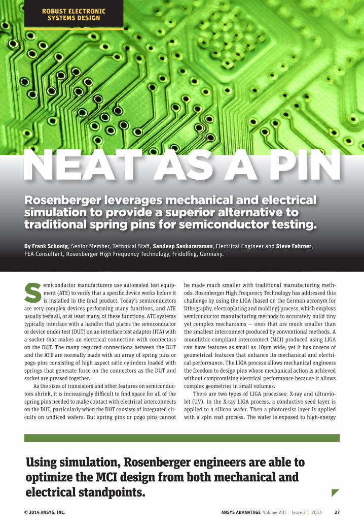
© 2014 ANSYS, INC. ANSYS ADVANTAGE Volume VIII | Issue 2 | 2014 27
NEAT AS A PIN
By Frank Schonig, Senior Member, Technical Staff; Sandeep Sankararaman, Electrical Engineer and Steve Fahrner, FEA Consultant, Rosenberger High Frequency Technology, Fridolfing, Germany.
Rosenberger leverages mechanical and electrical simulation to provide a superior alternative to traditional spring pins for semiconductor testing.
Semiconductor manufacturers use automated test equip-ment (ATE) to verify that a specific device works before it is installed in the final product. Today’s semiconductors
are very complex devices performing many functions, and ATE usually tests all, or at least many, of these functions. ATE systems typically interface with a handler that places the semiconductor or device under test (DUT) on an interface test adaptor (ITA) with a socket that makes an electrical connection with connectors on the DUT. The many required connections between the DUT and the ATE are normally made with an array of spring pins or pogo pins consisting of high aspect ratio cylinders loaded with springs that generate force on the connectors as the DUT and socket are pressed together.
As the sizes of transistors and other features on semiconduc-tors shrink, it is increasingly difficult to find space for all of the spring pins needed to make contact with electrical interconnects on the DUT, particularly when the DUT consists of integrated cir-cuits on undiced wafers. But spring pins or pogo pins cannot
be made much smaller with traditional manufacturing meth-ods. Rosenberger High Frequency Technology has addressed this challenge by using the LIGA (based on the German acronym for lithography, electroplating and molding) process, which employs semiconductor manufacturing methods to accurately build tiny yet complex mechanisms ― ones that are much smaller than the smallest interconnect produced by conventional methods. A monolithic-compliant interconnect (MCI) produced using LIGA can have features as small as 10μm wide, yet it has dozens of geometrical features that enhance its mechanical and electri-cal performance. The LIGA process allows mechanical engineers the freedom to design pins whose mechanical action is achieved without compromising electrical performance because it allows complex geometries in small volumes.
There are two types of LIGA processes: X-ray and ultravio-let (UV). In the X-ray LIGA process, a conductive seed layer is applied to a silicon wafer. Then a photoresist layer is applied with a spin coat process. The wafer is exposed to high-energy
ROBUST ELECTRONIC SYSTEMS DESIGN
Using simulation, Rosenberger engineers are able to optimize the MCI design from both mechanical and electrical standpoints.
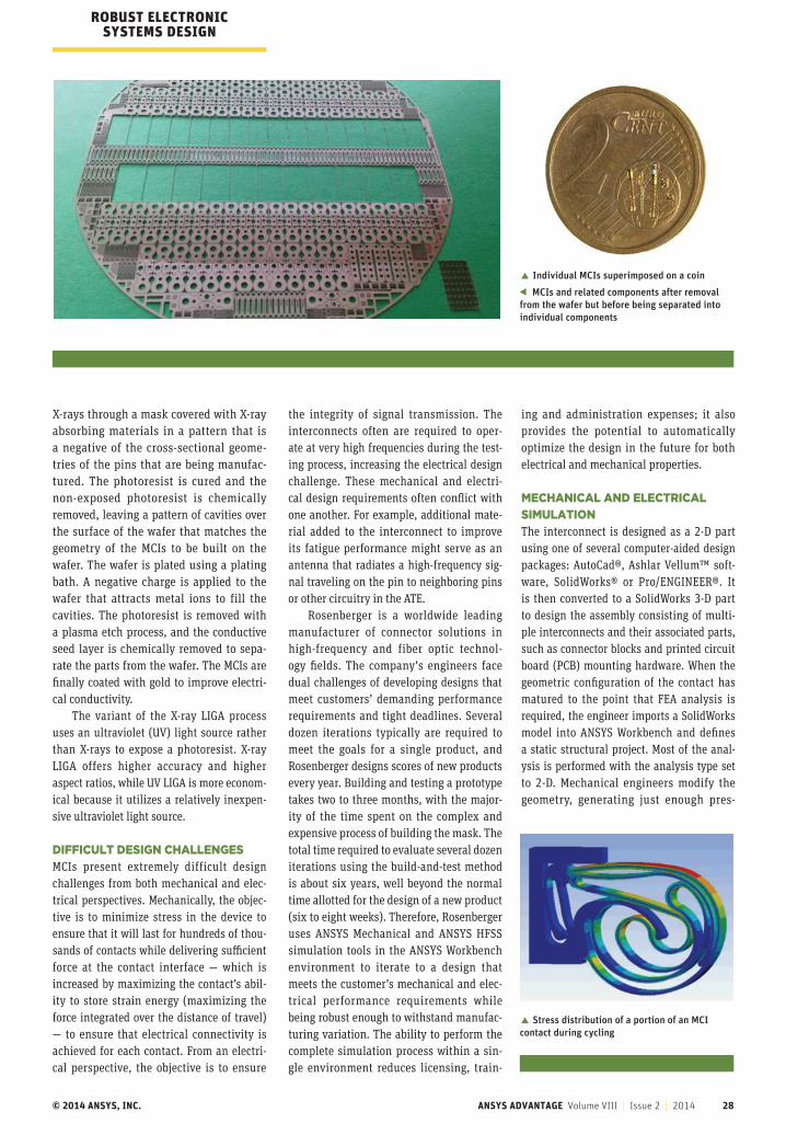
© 2014 ANSYS, INC. ANSYS ADVANTAGE Volume VIII | Issue 2 | 2014 28
X-rays through a mask covered with X-ray absorbing materials in a pattern that is a negative of the cross-sectional geome-tries of the pins that are being manufac-tured. The photoresist is cured and the non-exposed photoresist is chemically removed, leaving a pattern of cavities over the surface of the wafer that matches the geometry of the MCIs to be built on the wafer. The wafer is plated using a plating bath. A negative charge is applied to the wafer that attracts metal ions to fill the cavities. The photoresist is removed with a plasma etch process, and the conductive seed layer is chemically removed to sepa-rate the parts from the wafer. The MCIs are finally coated with gold to improve electri-cal conductivity.
The variant of the X-ray LIGA process uses an ultraviolet (UV) light source rather than X-rays to expose a photoresist. X-ray LIGA offers higher accuracy and higher aspect ratios, while UV LIGA is more econom-ical because it utilizes a relatively inexpen-sive ultraviolet light source.
DIFFICULT DESIGN CHALLENGESMCIs present extremely difficult design challenges from both mechanical and elec-trical perspectives. Mechanically, the objec-tive is to minimize stress in the device to ensure that it will last for hundreds of thou-sands of contacts while delivering sufficient force at the contact interface — which is increased by maximizing the contact’s abil-ity to store strain energy (maximizing the force integrated over the distance of travel) — to ensure that electrical connectivity is achieved for each contact. From an electri-cal perspective, the objective is to ensure
the integrity of signal transmission. The interconnects often are required to oper-ate at very high frequencies during the test-ing process, increasing the electrical design challenge. These mechanical and electri-cal design requirements often conflict with one another. For example, additional mate-rial added to the interconnect to improve its fatigue performance might serve as an antenna that radiates a high-frequency sig-nal traveling on the pin to neighboring pins or other circuitry in the ATE.
Rosenberger is a worldwide leading manufacturer of connector solutions in high-frequency and fiber optic technol-ogy fields. The company’s engineers face dual challenges of developing designs that meet customers’ demanding performance requirements and tight deadlines. Several dozen iterations typically are required to meet the goals for a single product, and Rosenberger designs scores of new products every year. Building and testing a prototype takes two to three months, with the major-ity of the time spent on the complex and expensive process of building the mask. The total time required to evaluate several dozen iterations using the build-and-test method is about six years, well beyond the normal time allotted for the design of a new product (six to eight weeks). Therefore, Rosenberger uses ANSYS Mechanical and ANSYS HFSS simulation tools in the ANSYS Workbench environment to iterate to a design that meets the customer’s mechanical and elec-trical performance requirements while being robust enough to withstand manufac-turing variation. The ability to perform the complete simulation process within a sin-gle environment reduces licensing, train-
ing and administration expenses; it also provides the potential to automatically optimize the design in the future for both electrical and mechanical properties.
MECHANICAL AND ELECTRICAL SIMULATIONThe interconnect is designed as a 2-D part using one of several computer-aided design packages: AutoCad®, Ashlar Vellum™ soft-ware, SolidWorks® or Pro/ENGINEER®. It is then converted to a SolidWorks 3-D part to design the assembly consisting of multi-ple interconnects and their associated parts, such as connector blocks and printed circuit board (PCB) mounting hardware. When the geometric configuration of the contact has matured to the point that FEA analysis is required, the engineer imports a SolidWorks model into ANSYS Workbench and defines a static structural project. Most of the anal-ysis is performed with the analysis type set to 2-D. Mechanical engineers modify the geometry, generating just enough pres-
� Individual MCIs superimposed on a coin MCIs and related components after removal
from the wafer but before being separated into individual components
ROBUST ELECTRONIC SYSTEMS DESIGN
� Stress distribution of a portion of an MCI contact during cycling
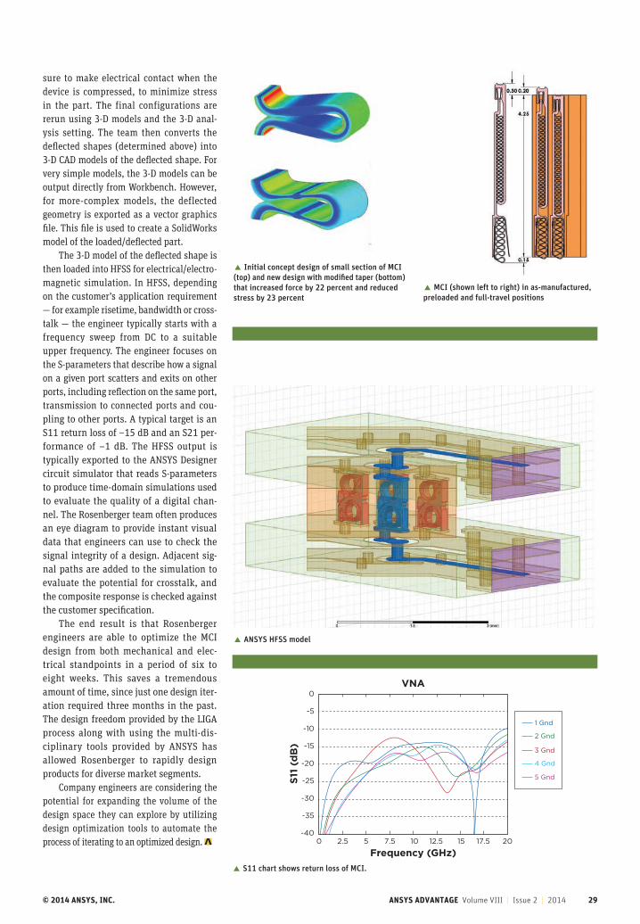
© 2014 ANSYS, INC. ANSYS ADVANTAGE Volume VIII | Issue 2 | 2014 29
� MCI (shown left to right) in as-manufactured, preloaded and full-travel positions
sure to make electrical contact when the device is compressed, to minimize stress in the part. The final configurations are rerun using 3-D models and the 3-D anal-ysis setting. The team then converts the deflected shapes (determined above) into 3-D CAD models of the deflected shape. For very simple models, the 3-D models can be output directly from Workbench. However, for more-complex models, the deflected geometry is exported as a vector graphics file. This file is used to create a SolidWorks model of the loaded/deflected part.
The 3-D model of the deflected shape is then loaded into HFSS for electrical/electro-magnetic simulation. In HFSS, depending on the customer’s application requirement — for example risetime, bandwidth or cross-talk — the engineer typically starts with a frequency sweep from DC to a suitable upper frequency. The engineer focuses on the S-parameters that describe how a signal on a given port scatters and exits on other ports, including reflection on the same port, transmission to connected ports and cou-pling to other ports. A typical target is an S11 return loss of –15 dB and an S21 per-formance of –1 dB. The HFSS output is typically exported to the ANSYS Designer circuit simulator that reads S-parameters to produce time-domain simulations used to evaluate the quality of a digital chan-nel. The Rosenberger team often produces an eye diagram to provide instant visual data that engineers can use to check the signal integrity of a design. Adjacent sig-nal paths are added to the simulation to evaluate the potential for crosstalk, and the composite response is checked against the customer specification.
The end result is that Rosenberger engineers are able to optimize the MCI design from both mechanical and elec-trical standpoints in a period of six to eight weeks. This saves a tremendous amount of time, since just one design iter-ation required three months in the past. The design freedom provided by the LIGA process along with using the multi-dis-ciplinary tools provided by ANSYS has allowed Rosenberger to rapidly design products for diverse market segments.
Company engineers are considering the potential for expanding the volume of the design space they can explore by utilizing design optimization tools to automate the process of iterating to an optimized design.
0
-5
-10
-15
-20
-25
-30
-35
-400 2.5 5 7.5 10 12.5 15 17.5 20
S11
(d
B)
VNA
Frequency (GHz)
1 Gnd
2 Gnd
3 Gnd
4 Gnd
5 Gnd
� Initial concept design of small section of MCI (top) and new design with modified taper (bottom) that increased force by 22 percent and reduced stress by 23 percent
� ANSYS HFSS model
� S11 chart shows return loss of MCI.
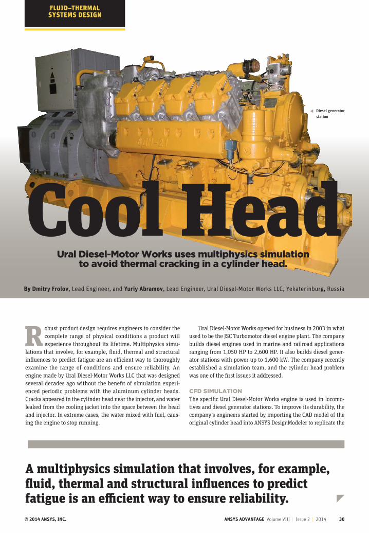
© 2014 ANSYS, INC. ANSYS ADVANTAGE Volume VIII | Issue 2 | 2014 30
FLUID–THERMAL SYSTEMS DESIGN
Ural Diesel-Motor Works uses multiphysics simulation to avoid thermal cracking in a cylinder head.
By Dmitry Frolov, Lead Engineer, and Yuriy Abramov, Lead Engineer, Ural Diesel-Motor Works LLC, Yekaterinburg, Russia
R obust product design requires engineers to consider the complete range of physical conditions a product will experience throughout its lifetime. Multiphysics simu-
lations that involve, for example, fluid, thermal and structural influences to predict fatigue are an efficient way to thoroughly examine the range of conditions and ensure reliability. An engine made by Ural Diesel-Motor Works LLC that was designed several decades ago without the benefit of simulation experi-enced periodic problems with the aluminum cylinder heads. Cracks appeared in the cylinder head near the injector, and water leaked from the cooling jacket into the space between the head and injector. In extreme cases, the water mixed with fuel, caus-ing the engine to stop running.
Ural Diesel-Motor Works opened for business in 2003 in what used to be the JSC Turbomotor diesel engine plant. The company builds diesel engines used in marine and railroad applications ranging from 1,050 HP to 2,600 HP. It also builds diesel gener-ator stations with power up to 1,600 kW. The company recently established a simulation team, and the cylinder head problem was one of the first issues it addressed.
CFD SIMULATIONThe specific Ural Diesel-Motor Works engine is used in locomo-tives and diesel generator stations. To improve its durability, the company’s engineers started by importing the CAD model of the original cylinder head into ANSYS DesignModeler to replicate the
Cool Head
A multiphysics simulation that involves, for example, fluid, thermal and structural influences to predict fatigue is an efficient way to ensure reliability.
Diesel generator station
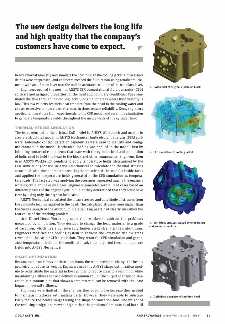
© 2014 ANSYS, INC. ANSYS ADVANTAGE Volume VIII | Issue 2 | 2014 31
Cool Head� CAD model of original aluminum block
� CFD simulation of cooling jacket
� Von Mises stresses caused by temperature and pressure on block
� Optimized geometry of cast-iron head
The new design delivers the long life and high quality that the company’s customers have come to expect.
head’s internal geometry and simulate the flow through the cooling jacket. Unnecessary details were suppressed, and engineers meshed the fluid region using tetrahedral ele-ments with an inflation layer near the wall for accurate resolution of the boundary layer.
Engineers opened the mesh in ANSYS CFX computational fluid dynamics (CFD) software and assigned properties for the fluid and boundary conditions. They sim-ulated the flow through the cooling jacket, looking for areas where fluid velocity is low. This low velocity restricts heat transfer from the head to the cooling water and causes excessive temperatures that can, in time, reduce reliability. Next, engineers applied temperatures from experiments to the CFD model and reran the simulation to generate temperature fields throughout the inside walls of the cylinder head.
THERMAL–STRESS SIMULATIONThe team returned to the original CAD model in ANSYS Workbench and used it to create a structural model in ANSYS Mechanical finite element analysis (FEA) soft-ware. Automatic contact detection capabilities were used to identify and config-ure contacts in the model. Mechanical loading was applied to the model, first by initiating contact of components that mate with the cylinder head and pretension of bolts used to hold the head to the block and other components. Engineers then used ANSYS Workbench coupling to apply temperature fields (determined by the CFD simulation) for use in ANSYS Mechanical to calculate the thermal stresses associated with these temperatures. Engineers selected the model’s inside faces and applied the temperature fields generated in the CFD simulation as tempera-ture loads. The last step was applying the pressures generated during the engine’s working cycle. In the early stages, engineers generated several load cases based on different phases of the engine cycle, but later they determined that they could save time by using only the highest load case.
ANSYS Mechanical calculated the mean stresses and amplitude of stresses from the complete loading applied to the head. The calculated stresses were higher than the yield strength of the aluminum material. Engineers had clearly identified the root cause of the cracking problem.
Ural Diesel-Motor Works engineers then worked to address the problems uncovered by simulation. They decided to change the head material to a grade of cast iron, which has a considerably higher yield strength than aluminum. Engineers modified the cooling system to address the low-velocity flow areas revealed in the earlier CFD simulation. They reran the CFD simulation and gener-ated temperature fields for the modified head, then imported these temperature fields into ANSYS Mechanical.
SHAPE OPTIMIZATIONBecause cast iron is heavier than aluminum, the team needed to change the head’s geometry to reduce its weight. Engineers used the ANSYS shape optimization mod-ule to redistribute the material in the cylinder to reduce mass to a minimum while maintaining stiffness above a defined minimum value. The output of shape optimi-zation is a contour plot that shows where material can be removed with the least impact on overall stiffness.
Engineers were limited in the changes they could make because they needed to maintain interfaces with mating parts. However, they were able to substan-tially reduce the head’s weight using the shape optimization tool. The weight of the resulting design is somewhat higher than the previous aluminum head but still
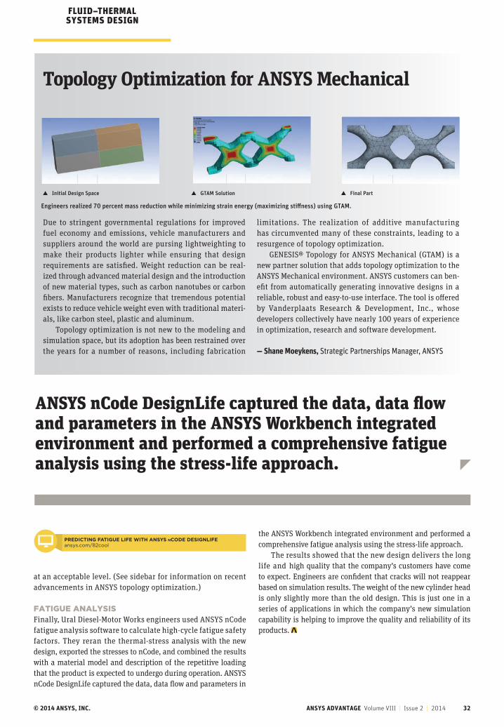
© 2014 ANSYS, INC. ANSYS ADVANTAGE Volume VIII | Issue 2 | 2014 32
Topology Optimization for ANSYS Mechanical
Due to stringent governmental regulations for improved fuel economy and emissions, vehicle manufacturers and suppliers around the world are pursing lightweighting to make their products lighter while ensuring that design requirements are satisfied. Weight reduction can be real-ized through advanced material design and the introduction of new material types, such as carbon nanotubes or carbon fibers. Manufacturers recognize that tremendous potential exists to reduce vehicle weight even with traditional materi-als, like carbon steel, plastic and aluminum.
Topology optimization is not new to the modeling and simulation space, but its adoption has been restrained over the years for a number of reasons, including fabrication
limitations. The realization of additive manufacturing has circumvented many of these constraints, leading to a resurgence of topology optimization.
GENESIS® Topology for ANSYS Mechanical (GTAM) is a new partner solution that adds topology optimization to the ANSYS Mechanical environment. ANSYS customers can ben-efit from automatically generating innovative designs in a reliable, robust and easy-to-use interface. The tool is offered by Vanderplaats Research & Development, Inc., whose developers collectively have nearly 100 years of experience in optimization, research and software development.
— Shane Moeykens, Strategic Partnerships Manager, ANSYS
Engineers realized 70 percent mass reduction while minimizing strain energy (maximizing stiffness) using GTAM.
at an acceptable level. (See sidebar for information on recent advancements in ANSYS topology optimization.)
FATIGUE ANALYSISFinally, Ural Diesel-Motor Works engineers used ANSYS nCode fatigue analysis software to calculate high-cycle fatigue safety factors. They reran the thermal-stress analysis with the new design, exported the stresses to nCode, and combined the results with a material model and description of the repetitive loading that the product is expected to undergo during operation. ANSYS nCode DesignLife captured the data, data flow and parameters in
ANSYS nCode DesignLife captured the data, data flow and parameters in the ANSYS Workbench integrated environment and performed a comprehensive fatigue analysis using the stress-life approach.
� GTAM Solution
FLUID–THERMAL SYSTEMS DESIGN
� Initial Design Space � Final Part
PREDICTING FATIGUE LIFE WITH ANSYS nCODE DESIGNLIFEansys.com/82cool
the ANSYS Workbench integrated environment and performed a comprehensive fatigue analysis using the stress-life approach.
The results showed that the new design delivers the long life and high quality that the company’s customers have come to expect. Engineers are confident that cracks will not reappear based on simulation results. The weight of the new cylinder head is only slightly more than the old design. This is just one in a series of applications in which the company’s new simulation capability is helping to improve the quality and reliability of its products.
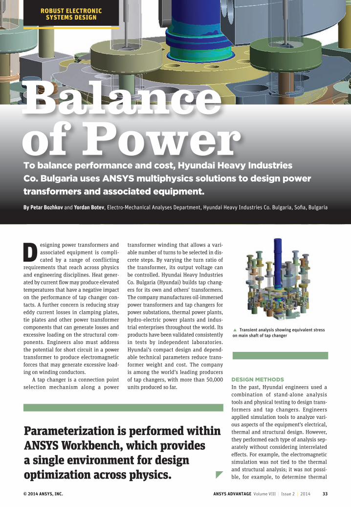
© 2014 ANSYS, INC. ANSYS ADVANTAGE Volume VIII | Issue 2 | 2014 33
D esigning power transformers and associated equipment is compli-cated by a range of conflicting
requirements that reach across physics and engineering disciplines. Heat gener-ated by current flow may produce elevated temperatures that have a negative impact on the performance of tap changer con-tacts. A further concern is reducing stray eddy current losses in clamping plates, tie plates and other power transformer components that can generate losses and excessive loading on the structural com-ponents. Engineers also must address the potential for short circuit in a power transformer to produce electromagnetic forces that may generate excessive load-ing on winding conductors.
A tap changer is a connection point selection mechanism along a power
transformer winding that allows a vari-able number of turns to be selected in dis-crete steps. By varying the turn ratio of the transformer, its output voltage can be controlled. Hyundai Heavy Industries Co. Bulgaria (Hyundai) builds tap chang-ers for its own and others' transformers. The company manufactures oil-immersed power transformers and tap changers for power substations, thermal power plants, hydro-electric power plants and indus-trial enterprises throughout the world. Its products have been validated consistently in tests by independent laboratories. Hyundai’s compact design and depend-able technical parameters reduce trans-former weight and cost. The company is among the world’s leading producers of tap changers, with more than 50,000 units produced so far.
DESIGN METHODSIn the past, Hyundai engineers used a combination of stand-alone analysis tools and physical testing to design trans-formers and tap changers. Engineers applied simulation tools to analyze vari-ous aspects of the equipment’s electrical, thermal and structural design. However, they performed each type of analysis sep-arately without considering interrelated effects. For example, the electromagnetic simulation was not tied to the thermal and structural analysis; it was not possi-ble, for example, to determine thermal
� Transient analysis showing equivalent stress on main shaft of tap changer
Balance of PowerBy Petar Bozhkov and Yordan Botev, Electro-Mechanical Analyses Department, Hyundai Heavy Industries Co. Bulgaria, Sofia, Bulgaria
To balance performance and cost, Hyundai Heavy Industries
Co. Bulgaria uses ANSYS multiphysics solutions to design power
transformers and associated equipment.
Parameterization is performed within ANSYS Workbench, which provides a single environment for design optimization across physics.
ROBUST ELECTRONIC SYSTEMS DESIGN
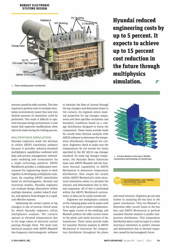
© 2014 ANSYS, INC. ANSYS ADVANTAGE Volume VIII | Issue 2 | 2014 34
stresses caused by eddy currents. The time required to perform tests in multiple simu-lation environments meant that only very limited amounts of simulation could be performed. This made it difficult to opti-mize first-pass design performance; it also meant that expensive modifications often had to be made during the trialing process.
MULTIPHYSICS SIMULATIONHyundai engineers made the decision to utilize ANSYS simulation software because it provides industry-standard multiphysics capabilities combined with data and process management, reduced-order modeling and cosimulation via a single technology platform. ANSYS Workbench provides a collaborative envi-ronment for engineering teams to work together in developing multiphysics solu-tions. By coupling ANSYS simulations based on electromagnetic, thermal and structural models, Hyundai engineers can evaluate design alternatives within multiple domains, conduct what-if stud-ies, and optimize final designs in a rapid, cost-effective manner.
Optimizing the contact system of tap changers is one of several critical areas for which Hyundai engineers utilize multiphysics analysis. The contacts operate at elevated temperatures due to the large values of electrical current passing through them. The team runs electrical analysis with ANSYS Maxwell low-frequency electromagnetic software
to simulate the flow of current through the tap changers and determine losses in the contacts. An engineer enters mate-rial properties for tap changer compo-nents and then specifies excitations and boundary conditions based on a volt-age distribution designed to stress the components. These losses provide loads for steady-state thermal analysis with ANSYS software to determine the temper-ature distribution throughout the con-tacts. Engineers check to make sure the temperatures do not exceed the limits specified in the IEC 60214 tap changer standard. On some tap changer compo-nents, the Hyundai Heavy Industries team uses ANSYS Maxwell and the tran-sient thermal capabilities in ANSYS Mechanical to determine temperature distribution, then couple the results within ANSYS Mechanical’s static-struc-tural simulation solver to calculate the stresses and deformations due to ther-mal expansion. All of this is performed within the ANSYS Workbench environ-ment, so data can be easily transferred.
Engineers use multiphysics analysis on the clamping plates and tie plates used in the active parts of power transformers. They apply current in the windings, and Maxwell predicts the eddy current losses in the plates and metal structure of the transformer. These losses provide loads for transient thermal analysis in ANSYS Mechanical to determine the tempera-ture distribution throughout the plates
and metal structure. Engineers go one step further in analyzing the bus bars in the power transformer: They use Maxwell to determine eddy current losses in the bus bars and ANSYS Mechanical to perform transient thermal analysis to predict tem-perature distribution. This temperature distribution data is used as input to a static structural simulation to predict stresses and deformations due to thermal expan-sion caused by electromagnetic forces.
Hyundai reduced engineering costs by up to 5 percent. It expects to achieve up to 15 percent cost reduction in the future through multiphysics simulation.
� Three winding power transformer
� Current density in bus bars, flexible connections and bushings of transformer
ROBUST ELECTRONIC SYSTEMS DESIGN
ELECTROMAGNETIC AND THERMAL MULTIPHYSICS ANALYSISansys.com/82balance
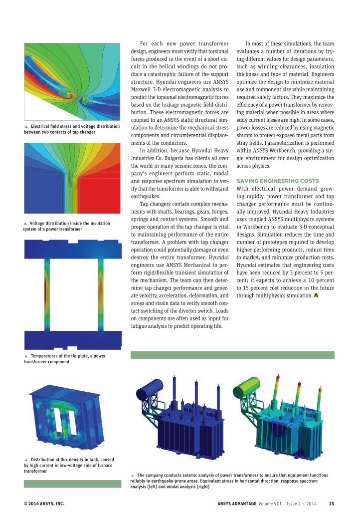
© 2014 ANSYS, INC. ANSYS ADVANTAGE Volume VIII | Issue 2 | 2014 35
� Electrical field stress and voltage distribution between two contacts of tap changer
� The company conducts seismic analysis of power transformers to ensure that equipment functions reliably in earthquake-prone areas. Equivalent stress in horizontal direction: response spectrum analysis (left) and modal analysis (right)
� Voltage distribution inside the insulation system of a power transformer
� Temperatures of the tie-plate, a power transformer component
For each new power transformer design, engineers must verify that torsional forces produced in the event of a short cir-cuit in the helical windings do not pro-duce a catastrophic failure of the support structure. Hyundai engineers use ANSYS Maxwell 3-D electromagnetic analysis to predict the torsional electromagnetic forces based on the leakage magnetic field distri-bution. These electromagnetic forces are coupled to an ANSYS static structural sim-ulation to determine the mechanical stress components and circumferential displace-ments of the conductors.
In addition, because Hyundai Heavy Industries Co. Bulgaria has clients all over the world in many seismic zones, the com-pany’s engineers perform static, modal and response spectrum simulation to ver-ify that the transformer is able to withstand earthquakes.
Tap changers contain complex mecha-nisms with shafts, bearings, gears, hinges, springs and contact systems. Smooth and proper operation of the tap changer is vital to maintaining performance of the entire transformer. A problem with tap changer operation could potentially damage or even destroy the entire transformer. Hyundai engineers use ANSYS Mechanical to per-form rigid/flexible transient simulation of the mechanism. The team can then deter-mine tap changer performance and gener-ate velocity, acceleration, deformation, and stress and strain data to verify smooth con-tact switching of the diverter switch. Loads on components are often used as input for fatigue analysis to predict operating life.
In most of these simulations, the team evaluates a number of iterations by try-ing different values for design parameters, such as winding clearances, insulation thickness and type of material. Engineers optimize the design to minimize material use and component size while maintaining required safety factors. They maximize the efficiency of a power transformer by remov-ing material when possible in areas where eddy current losses are high. In some cases, power losses are reduced by using magnetic shunts to protect exposed metal parts from stray fields. Parameterization is performed within ANSYS Workbench, providing a sin-gle environment for design optimization across physics.
SAVING ENGINEERING COSTSWith electrical power demand grow-ing rapidly, power transformer and tap changer performance must be continu-ally improved. Hyundai Heavy Industries uses coupled ANSYS multiphysics systems in Workbench to evaluate 3-D conceptual designs. Simulation reduces the time and number of prototypes required to develop higher-performing products, reduce time to market, and minimize production costs. Hyundai estimates that engineering costs have been reduced by 3 percent to 5 per-cent; it expects to achieve a 10 percent to 15 percent cost reduction in the future through multiphysics simulation.
� Distribution of flux density in tank, caused by high current in low-voltage side of furnace transformer

© 2014 ANSYS, INC. ANSYS ADVANTAGE Volume VIII | Issue 2 | 2014 36
By Martin Perterer, Head of Research and Simulation, KTM Technologies GmbH, Salzburg, Austria
Getting Around in Style
Engineers quickly and reliably design a composites sports car and an electric bicycle using ANSYS technology.
ADVANCED MATERIALS SYSTEMS DESIGN
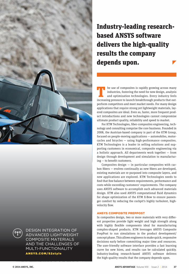
© 2014 ANSYS, INC. ANSYS ADVANTAGE Volume VIII | Issue 2 | 2014 37
T he use of composites is rapidly growing across many industries, fostering the need for new design, analysis and optimization technologies. Every industry feels
increasing pressure to launch breakthrough products that out-perform competitors and meet market needs. For many design applications that require strong yet lightweight materials, lay-ered composites are ideal. Even so, faster, more frequent prod-uct introductions and new technologies cannot compromise ultimate product quality, reliability and speed to market.
For KTM Technologies, fiber-composites engineering, tech-nology and consulting comprise the core business. Founded in 2008, the Austrian-based company is part of the KTM Group, focused on people-moving applications ― automobiles, motor-cycles and bicycles — using high-performance composites. KTM Technologies is a leader in selling solutions and sup-porting customers in economical, composite engineering via a holistic approach. All departments work together — from design through development and simulation to manufactur-ing — to benefit customers.
Composites design — in particular composites with car-bon fibers — evolves continually as new fibers are developed, existing materials are re-purposed into composite layers, and new applications are explored. KTM Technologies needs to find that fine balance between requirements, performance and costs while exceeding customers’ requirements. The company uses ANSYS software to accomplish such advanced materials design. KTM also used ANSYS computational fluid dynamics for shape optimization of the KTM X-Bow to ensure passen-ger comfort by reducing the cockpit’s highly turbulent, high-velocity flow.
ANSYS COMPOSITE PREPPOST In composites design, two or more materials with very differ-ent properties provide light weight and high strength along with highly flexible components ideal for manufacturing complex-shaped products. KTM leverages ANSYS Composite PrepPost to run simulations in the product development/ concept phase. This allows engineers to make quick, responsive decisions early before committing major time and resources. The user-friendly software interface provides a fast learning curve for new hires, and results can be calculated quickly. Industry-leading research-based ANSYS software delivers the high-quality results that the company depends upon.
DESIGN INTEGRATION OF ADVANCED LIGHTWEIGHT COMPOSITE MATERIALS AND THE CHALLENGES OF MULTI-FUNCTIONALITY ANSYS.COM/82sty le
Industry-leading research-based ANSYS software delivers the high-quality results the company depends upon.
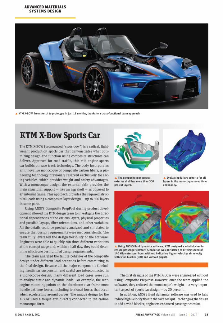
© 2014 ANSYS, INC. ANSYS ADVANTAGE Volume VIII | Issue 2 | 2014 38
The KTM X-BOW (pronounced “cross-bow”) is a radical, light-weight production sports car that demonstrates what opti-mizing design and function using composite structures can deliver. Approved for road traffic, this mid-engine sports car builds on race track technology. The body incorporates an innovative monocoque of composite carbon fibers, a pio-neering technology previously reserved exclusively for rac-ing vehicles, which provides weight and safety advantages. With a monocoque design, the external skin provides the main structural support — like an egg shell — as opposed to an internal frame. This approach provides the required struc-tural loads using a composite layer design — up to 300 layers in some parts.
Using ANSYS Composite PrepPost during product devel-opment allowed the KTM design team to investigate the direc-tional dependencies of the various layers, physical properties and possible layups, fiber orientations, and other variables. All the details could be precisely analyzed and simulated to ensure that design requirements were met consistently. The team fully leveraged the design flexibility of the software. Engineers were able to quickly run three different variations at the concept stage and, within a half day, they could deter-mine which one best fulfilled design requirements.
The team analyzed the failure behavior of the composite design under different load scenarios before committing to the final design. Because all the major components (includ-ing front/rear suspension and seats) are interconnected in a monocoque design, many different load cases were run to analyze static and dynamic loads. For example, the rear-engine mounting points on the aluminum rear frame must handle extreme forces, including torsional forces that occur when accelerating around curves. The unique design for the X-BOW used a torque arm directly connected to the carbon monocoque form.
KTM X-Bow Sports Car
� KTM X-BOW, from sketch to prototype in just 18 months, thanks to a cross-functional team approach
The first designs of the KTM X-BOW were engineered without using Composite PrepPost. However, once the team applied the software, they reduced the monocoque’s weight — a very impor-tant aspect of sports car design — by 20 percent.
In addition, ANSYS fluid dynamics software was used to help reduce high-velocity flow in the car’s cockpit. By changing the design to add a wind blocker, engineers enhanced passenger comfort.
� Evaluating failure criteria for all layers in the monocoque saved time and money.
� The composite monocoque exterior shell has more than 300 pre-cut layers.
� Using ANSYS fluid dynamics software, KTM designed a wind blocker to ensure passenger comfort. Simulation was performed at driving speed of 140 kilometers per hour, with red indicating higher velocity: air velocity with wind blocker (left) and without (right).
ADVANCED MATERIALS SYSTEMS DESIGN
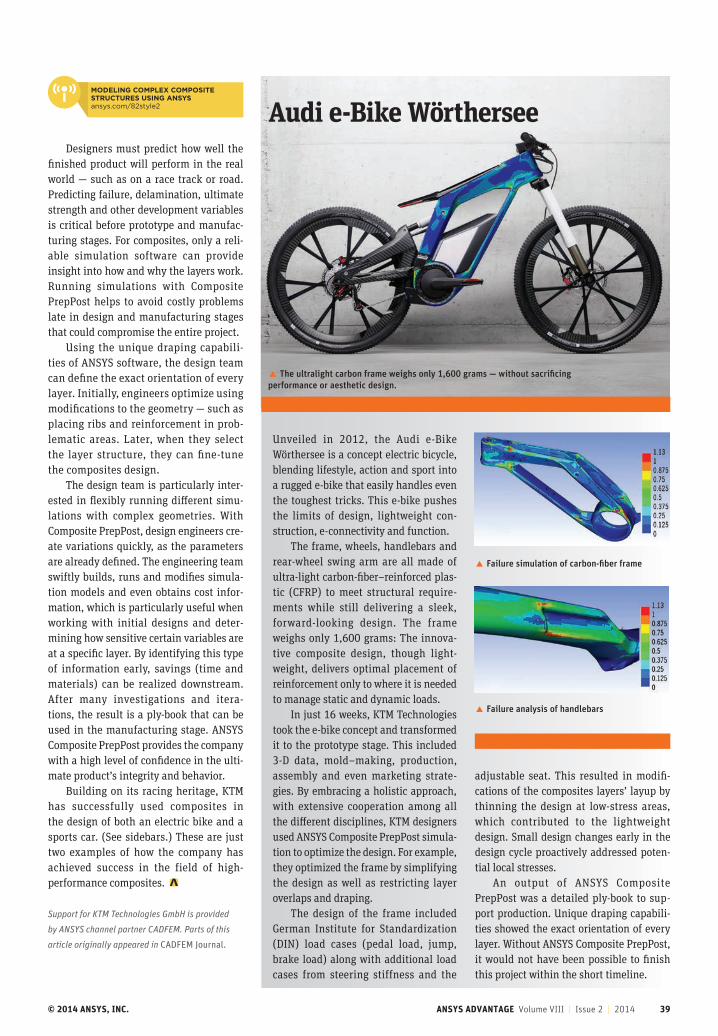
© 2014 ANSYS, INC. ANSYS ADVANTAGE Volume VIII | Issue 2 | 2014 39
Unveiled in 2012, the Audi e-Bike Wörthersee is a concept electric bicycle, blending lifestyle, action and sport into a rugged e-bike that easily handles even the toughest tricks. This e-bike pushes the limits of design, lightweight con-struction, e-connectivity and function.
The frame, wheels, handlebars and rear-wheel swing arm are all made of ultra-light carbon-fiber–reinforced plas-tic (CFRP) to meet structural require-ments while still delivering a sleek, forward-looking design. The frame weighs only 1,600 grams: The innova-tive composite design, though light-weight, delivers optimal placement of reinforcement only to where it is needed to manage static and dynamic loads.
In just 16 weeks, KTM Technologies took the e-bike concept and transformed it to the prototype stage. This included 3-D data, mold–making, production, assembly and even marketing strate-gies. By embracing a holistic approach, with extensive cooperation among all the different disciplines, KTM designers used ANSYS Composite PrepPost simula-tion to optimize the design. For example, they optimized the frame by simplifying the design as well as restricting layer overlaps and draping.
The design of the frame included German Institute for Standardization (DIN) load cases (pedal load, jump, brake load) along with additional load cases from steering stiffness and the
Audi e-Bike Wörthersee
� The ultralight carbon frame weighs only 1,600 grams — without sacrificing performance or aesthetic design.
� Failure simulation of carbon-fiber frame
� Failure analysis of handlebars
adjustable seat. This resulted in modifi-cations of the composites layers’ layup by thinning the design at low-stress areas, which contributed to the lightweight design. Small design changes early in the design cycle proactively addressed poten-tial local stresses.
An output of ANSYS Composite PrepPost was a detailed ply-book to sup-port production. Unique draping capabili-ties showed the exact orientation of every layer. Without ANSYS Composite PrepPost, it would not have been possible to finish this project within the short timeline.
Designers must predict how well the finished product will perform in the real world — such as on a race track or road. Predicting failure, delamination, ultimate strength and other development variables is critical before prototype and manufac-turing stages. For composites, only a reli-able simulation software can provide insight into how and why the layers work. Running simulations with Composite PrepPost helps to avoid costly problems late in design and manufacturing stages that could compromise the entire project.
Using the unique draping capabili-ties of ANSYS software, the design team can define the exact orientation of every layer. Initially, engineers optimize using modifications to the geometry — such as placing ribs and reinforcement in prob-lematic areas. Later, when they select the layer structure, they can fine-tune the composites design.
The design team is particularly inter-ested in flexibly running different simu-lations with complex geometries. With Composite PrepPost, design engineers cre-ate variations quickly, as the parameters are already defined. The engineering team swiftly builds, runs and modifies simula-tion models and even obtains cost infor-mation, which is particularly useful when working with initial designs and deter-mining how sensitive certain variables are at a specific layer. By identifying this type of information early, savings (time and materials) can be realized downstream. After many investigations and itera-tions, the result is a ply-book that can be used in the manufacturing stage. ANSYS Composite PrepPost provides the company with a high level of confidence in the ulti-mate product’s integrity and behavior.
Building on its racing heritage, KTM has successfully used composites in the design of both an electric bike and a sports car. (See sidebars.) These are just two examples of how the company has achieved success in the field of high- performance composites.
Support for KTM Technologies GmbH is provided
by ANSYS channel partner CADFEM. Parts of this
article originally appeared in CADFEM Journal.
MODELING COMPLEX COMPOSITE STRUCTURES USING ANSYSansys.com/82style2
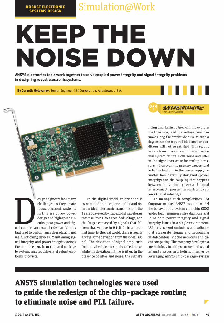
© 2014 ANSYS, INC. ANSYS ADVANTAGE Volume VIII | Issue 2 | 2014 40
Simulation@Work
KEEP THE NOISE DOWNANSYS electronics tools work together to solve coupled power integrity and signal integrity problems in designing robust electronic systems.
By Cornelia Golovanov, Senior Engineer, LSI Corporation, Allentown, U.S.A.
Design engineers face many challenges as they create robust electronic systems. In this era of low-power design and high-speed cir-cuits, poor power and sig-
nal quality can result in design failures that lead to performance degradation and malfunctioning devices. Maintaining sig-nal integrity and power integrity across the entire design, from chip and package to system, ensures delivery of robust elec-tronic products.
ANSYS simulation technologies were used to guide the redesign of the chip–package routing to eliminate noise and PLL failure.
ROBUST ELECTRONIC SYSTEMS DESIGN
In the digital world, information is transmitted in a sequence of 1s and 0s. In an ideal electronic transmission, the 1s are conveyed by trapezoidal waveforms that rise from 0 to a specified voltage, and the 0s get conveyed by signals that fall from that voltage to 0 (bit 0) in a speci-fied time. In the real world, there is nearly always some deviation from this ideal sig-nal. The deviation of signal amplitude from ideal voltage is simply called noise, while the deviation in time is jitter. In the presence of jitter and noise, the signal’s
rising and falling edges can move along the time axis, and the voltage level can move along the amplitude axis, to such a degree that the required bit detection con-ditions will not be satisfied. This results in data transmission corruption and even-tual system failure. Both noise and jitter in the signal can arise for multiple rea-sons — however, the primary causes tend to be fluctuations in the power supply no matter how carefully designed (power integrity) and the coupling that happens between the various power and signal interconnects present in electronic sys-tems (signal integrity).
To manage such complexities, LSI Corporation uses ANSYS tools to model the behavior of a system on a chip (SOC) under load; engineers also diagnose and solve both power integrity and signal integrity issues in a single environment. LSI designs semiconductors and software that accelerate storage and networking in datacenters, mobile networks and cli-ent computing. The company developed a methodology to address power and signal integrity issues in a holistic manner by leveraging ANSYS chip–package–system
LSI DISCUSSES ROBUST ELECTRICAL AND ELECTRONICS SYSTEM DESIGNansys.com/82noise
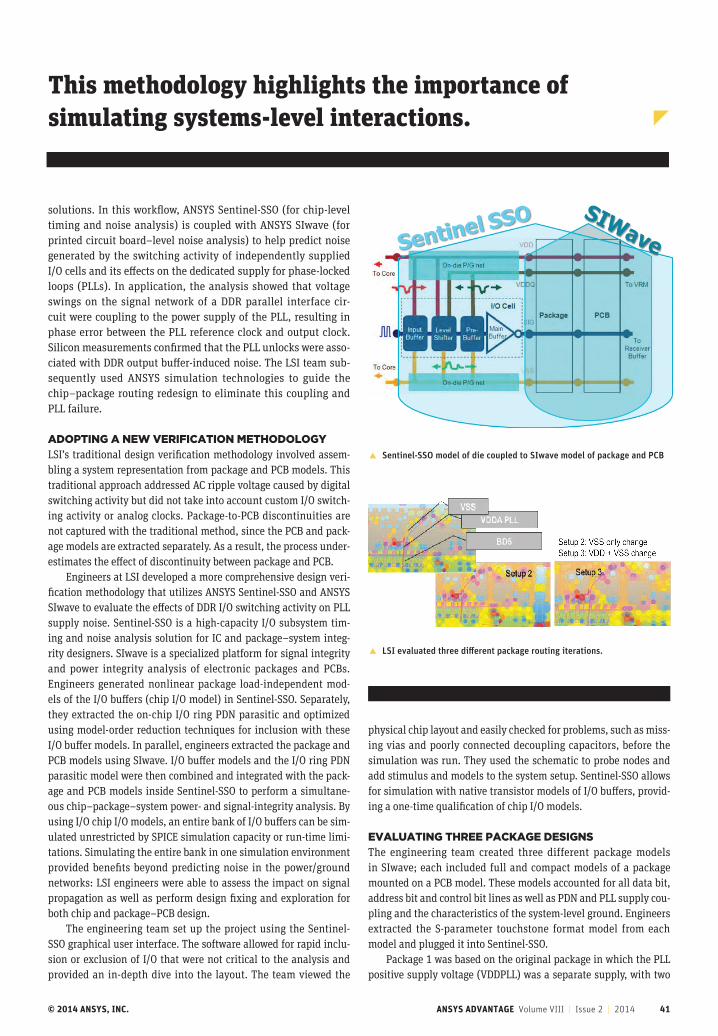
© 2014 ANSYS, INC. ANSYS ADVANTAGE Volume VIII | Issue 2 | 2014 41
� LSI evaluated three different package routing iterations.
� Sentinel-SSO model of die coupled to SIwave model of package and PCB
solutions. In this workflow, ANSYS Sentinel-SSO (for chip-level timing and noise analysis) is coupled with ANSYS SIwave (for printed circuit board–level noise analysis) to help predict noise generated by the switching activity of independently supplied I/O cells and its effects on the dedicated supply for phase-locked loops (PLLs). In application, the analysis showed that voltage swings on the signal network of a DDR parallel interface cir-cuit were coupling to the power supply of the PLL, resulting in phase error between the PLL reference clock and output clock. Silicon measurements confirmed that the PLL unlocks were asso-ciated with DDR output buffer-induced noise. The LSI team sub-sequently used ANSYS simulation technologies to guide the chip–package routing redesign to eliminate this coupling and PLL failure.
ADOPTING A NEW VERIFICATION METHODOLOGYLSI’s traditional design verification methodology involved assem-bling a system representation from package and PCB models. This traditional approach addressed AC ripple voltage caused by digital switching activity but did not take into account custom I/O switch-ing activity or analog clocks. Package-to-PCB discontinuities are not captured with the traditional method, since the PCB and pack-age models are extracted separately. As a result, the process under-estimates the effect of discontinuity between package and PCB.
Engineers at LSI developed a more comprehensive design veri-fication methodology that utilizes ANSYS Sentinel-SSO and ANSYS SIwave to evaluate the effects of DDR I/O switching activity on PLL supply noise. Sentinel-SSO is a high-capacity I/O subsystem tim-ing and noise analysis solution for IC and package–system integ-rity designers. SIwave is a specialized platform for signal integrity and power integrity analysis of electronic packages and PCBs. Engineers generated nonlinear package load-independent mod-els of the I/O buffers (chip I/O model) in Sentinel-SSO. Separately, they extracted the on-chip I/O ring PDN parasitic and optimized using model-order reduction techniques for inclusion with these I/O buffer models. In parallel, engineers extracted the package and PCB models using SIwave. I/O buffer models and the I/O ring PDN parasitic model were then combined and integrated with the pack-age and PCB models inside Sentinel-SSO to perform a simultane-ous chip–package–system power- and signal-integrity analysis. By using I/O chip I/O models, an entire bank of I/O buffers can be sim-ulated unrestricted by SPICE simulation capacity or run-time limi-tations. Simulating the entire bank in one simulation environment provided benefits beyond predicting noise in the power/ground networks: LSI engineers were able to assess the impact on signal propagation as well as perform design fixing and exploration for both chip and package–PCB design.
The engineering team set up the project using the Sentinel-SSO graphical user interface. The software allowed for rapid inclu-sion or exclusion of I/O that were not critical to the analysis and provided an in-depth dive into the layout. The team viewed the
physical chip layout and easily checked for problems, such as miss-ing vias and poorly connected decoupling capacitors, before the simulation was run. They used the schematic to probe nodes and add stimulus and models to the system setup. Sentinel-SSO allows for simulation with native transistor models of I/O buffers, provid-ing a one-time qualification of chip I/O models.
EVALUATING THREE PACKAGE DESIGNSThe engineering team created three different package models in SIwave; each included full and compact models of a package mounted on a PCB model. These models accounted for all data bit, address bit and control bit lines as well as PDN and PLL supply cou-pling and the characteristics of the system-level ground. Engineers extracted the S-parameter touchstone format model from each model and plugged it into Sentinel-SSO.
Package 1 was based on the original package in which the PLL positive supply voltage (VDDPLL) was a separate supply, with two
This methodology highlights the importance of simulating systems-level interactions.
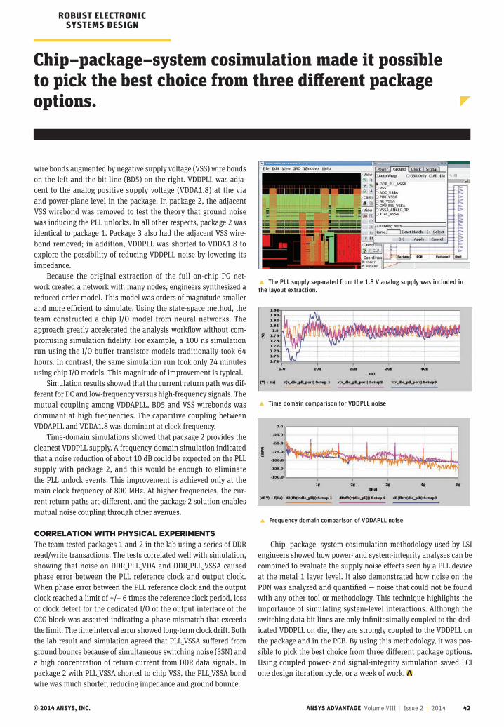
© 2014 ANSYS, INC. ANSYS ADVANTAGE Volume VIII | Issue 2 | 2014 42
wire bonds augmented by negative supply voltage (VSS) wire bonds on the left and the bit line (BD5) on the right. VDDPLL was adja-cent to the analog positive supply voltage (VDDA1.8) at the via and power-plane level in the package. In package 2, the adjacent VSS wirebond was removed to test the theory that ground noise was inducing the PLL unlocks. In all other respects, package 2 was identical to package 1. Package 3 also had the adjacent VSS wire-bond removed; in addition, VDDPLL was shorted to VDDA1.8 to explore the possibility of reducing VDDPLL noise by lowering its impedance.
Because the original extraction of the full on-chip PG net-work created a network with many nodes, engineers synthesized a reduced-order model. This model was orders of magnitude smaller and more efficient to simulate. Using the state-space method, the team constructed a chip I/O model from neural networks. The approach greatly accelerated the analysis workflow without com-promising simulation fidelity. For example, a 100 ns simulation run using the I/O buffer transistor models traditionally took 64 hours. In contrast, the same simulation run took only 24 minutes using chip I/O models. This magnitude of improvement is typical.
Simulation results showed that the current return path was dif-ferent for DC and low-frequency versus high-frequency signals. The mutual coupling among VDDAPLL, BD5 and VSS wirebonds was dominant at high frequencies. The capacitive coupling between VDDAPLL and VDDA1.8 was dominant at clock frequency.
Time-domain simulations showed that package 2 provides the cleanest VDDPLL supply. A frequency-domain simulation indicated that a noise reduction of about 10 dB could be expected on the PLL supply with package 2, and this would be enough to eliminate the PLL unlock events. This improvement is achieved only at the main clock frequency of 800 MHz. At higher frequencies, the cur-rent return paths are different, and the package 2 solution enables mutual noise coupling through other avenues.
CORRELATION WITH PHYSICAL EXPERIMENTSThe team tested packages 1 and 2 in the lab using a series of DDR read/write transactions. The tests correlated well with simulation, showing that noise on DDR_PLL_VDA and DDR_PLL_VSSA caused phase error between the PLL reference clock and output clock. When phase error between the PLL reference clock and the output clock reached a limit of +/– 6 times the reference clock period, loss of clock detect for the dedicated I/O of the output interface of the CCG block was asserted indicating a phase mismatch that exceeds the limit. The time interval error showed long-term clock drift. Both the lab result and simulation agreed that PLL_VSSA suffered from ground bounce because of simultaneous switching noise (SSN) and a high concentration of return current from DDR data signals. In package 2 with PLL_VSSA shorted to chip VSS, the PLL_VSSA bond wire was much shorter, reducing impedance and ground bounce.
� The PLL supply separated from the 1.8 V analog supply was included in the layout extraction.
Chip–package–system cosimulation made it possible to pick the best choice from three different package options.
� Frequency domain comparison of VDDAPLL noise
� Time domain comparison for VDDPLL noise
ROBUST ELECTRONIC SYSTEMS DESIGN
Chip–package–system cosimulation methodology used by LSI engineers showed how power- and system-integrity analyses can be combined to evaluate the supply noise effects seen by a PLL device at the metal 1 layer level. It also demonstrated how noise on the PDN was analyzed and quantified — noise that could not be found with any other tool or methodology. This technique highlights the importance of simulating system-level interactions. Although the switching data bit lines are only infinitesimally coupled to the ded-icated VDDPLL on die, they are strongly coupled to the VDDPLL on the package and in the PCB. By using this methodology, it was pos-sible to pick the best choice from three different package options. Using coupled power- and signal-integrity simulation saved LCI one design iteration cycle, or a week of work.
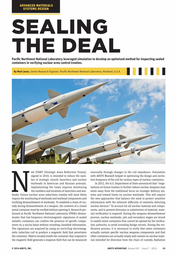
© 2014 ANSYS, INC. ANSYS ADVANTAGE Volume VIII | Issue 2 | 2014 43
SEALING THE DEALPacific Northwest National Laboratory leveraged simulation to develop an optimized method for inspecting sealed containers in verifying nuclear arms control treaties.
By Mark Jones, Senior Research Engineer, Pacific Northwest National Laboratory, Richland, U.S.A.
New START (Strategic Arms Reduction Treaty), signed in 2010, is intended to reduce the num-ber of strategic missile launchers and nuclear warheads in American and Russian arsenals. Implementing the treaty requires monitoring the numbers and locations of launchers and war-
heads. Future nuclear arms reductions treaties will most likely require the monitoring of warheads and warhead components and verifying dismantlement of warheads. To establish a chain of cus-tody during dismantlement of a weapon, the contents of a closed metal container must be verified without opening it. Research per-formed at Pacific Northwest National Laboratory (PNNL) demon-strates that low-frequency electromagnetic signatures of sealed metallic containers can confirm the presence of specific compo-nents on a yes/no basis without revealing classified information. The signatures are acquired by using an encircling electromag-netic induction coil to produce a magnetic field that penetrates the container. Objects located inside the container that respond to the magnetic field generate a response field that can be measured
externally through changes in the coil impedance. Simulation with ANSYS Maxwell helped in optimizing the design and excita-tion frequency of the coil for various types of nuclear containers.
In 2012, the U.S. Department of State announced that “nego-tiations on future treaties to further reduce nuclear weapons may move away from the traditional focus on strategic delivery sys-tems and toward limits on nuclear warheads. This will require the new approaches that balance the need to protect sensitive information with the inherent difficulty of remotely detecting nuclear devices.” To account for all nuclear material and compo-nents, and to prevent diversion or substitution of material, mate-rial verification is required. During the weapons dismantlement process, nuclear warheads, pits and secondary stages are stored in sealed metal containers that cannot be opened by the verifica-tion authority, to avoid revealing design secrets. During the ver-ification process, it is necessary to verify that some containers actually contain specific nuclear weapons components and that other containers are actually empty and contain no nuclear mate-rial intended for diversion from the chain of custody. Radiation
ADVANCED MATERIALS SYSTEMS DESIGN
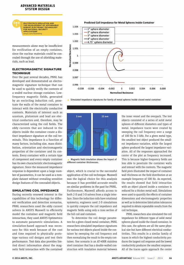
© 2014 ANSYS, INC. ANSYS ADVANTAGE Volume VIII | Issue 2 | 2014 44
ADVANCED MATERIALS SYSTEM DESIGN
measurements alone may be insufficient for verification of an empty container, since the nuclear materials could be con-cealed through the use of shielding mate-rials, such as lead.
ELECTROMAGNETIC SIGNATURE TECHNIQUEOver the past several decades, PNNL has developed and demonstrated an electro-magnetic signature technique that can be used to quickly verify the contents of a sealed nuclear storage container. Low-frequency magnetic fields, generated by an encircling induction coil, pene-trate the walls of the metal container to interact with the electrically conductive contents. Materials of interest such as uranium, plutonium and lead are elec-trical conductors and, therefore, may be characterized using the coil fields. The eddy currents that are induced in the objects inside the container create a dis-tinct impedance signature at the coil ter-minals. This impedance is a function of many factors, including size, mass distri-bution, orientation and electromagnetic properties of the container and its con-tents. Every container with a certain type of component and every empty container has its own characteristic electromagnetic signature. Since the measured impedance response is dependent upon a large num-ber of parameters, it can be used as a tem-plate dataset without revealing sensitive design features of the concealed objects.
SIMULATING COIL IMPEDANCEDuring recently renewed interest in the capabilities of this technology for differ-ent verification and detection scenarios, PNNL researchers used the eddy current solvers in ANSYS Maxwell to efficiently model the container and magnetic field interaction; they used ANSYS Optimetrics to automate parametric simulations. A simulation-based approach was neces-sary for this work because of the cost and time required to physically proto-type various coil designs and test their performance. Test data also provides lim-ited direct information about the mag-netic field interaction with the contained
object, which is crucial to the successful application of the coil technique. Maxwell was the logical choice for this analysis because it has provided accurate results on similar problems in the past for PNNL. Furthermore, Maxwell affords access to both 2-D and 3-D solvers from a single inter-face. Since the induction coils have rotational symmetry, engineers used 2-D simulations to quickly compute the coil impedance and magnetic fields using only a cross section of the full coil and container.
To determine the coil design parame-ters for a given closed metal container, PNNL researchers simulated impedance signatures for various test objects placed inside the con-tainer by sweeping the coil frequency and then normalizing the result to the empty con-tainer. One scenario is an AT-400R stainless steel container that has a double-walled con-struction with insulation material between
� Simulated impedance signatures for family of metal spheres inside closed metal container
the inner vessel and the overpack. The test objects consisted of a series of solid metal spheres of different diameters and types of metal. Impedance traces were created by sweeping the coil frequency over a range of 100 Hz to 3 kHz. For a given metal type, the smallest test object produced the small-est impedance variation, while the largest sphere produced the largest impedance vari-ation. All of the responses approached the center of the plot as frequency increased. This is because higher-frequency fields are less able to penetrate the container walls and interact with the contents. The magnetic field plots illustrated the impact of container wall thickness on the field distribution at an example frequency of 500 Hz. As expected, the results showed that field interaction with an object placed inside a container is reduced for a thicker metal wall. Simulations were used to quantify the effects of container dimensions and electromagnetic properties as well as to determine fabrication tolerances required to obtain repeatable results from the coil technique.
PNNL researchers also simulated the coil impedance for different types of solid metal spheres placed inside the closed container. In this case, the spheres are all the same phys-ical size but have different electrical conduc-tivities. This results in a similar family of traces in which the highest conductivity pro-duces the largest coil response and the lowest conductivity produces the smallest response. All of the traces again approach the center
� Magnetic field simulation shows the impact of different container thicknesses.
5 mm 25 mm
MULTIPHYSICS SIMULATION AND THE DEVELOPMENT OF AFFORDABLE ROBUST ELECTRONIC TECHNOLOGY FOR NATIONAL SECURITY APPLICATIONSansys.com/82sealing
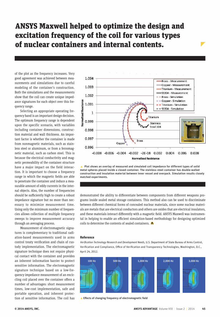
© 2014 ANSYS, INC. ANSYS ADVANTAGE Volume VIII | Issue 2 | 2014 45
of the plot as the frequency increases. Very good agreement was achieved between mea-surements and simulations due to careful modeling of the container’s construction. Both the simulations and the measurements show that the coil can create unique imped-ance signatures for each object over this fre-quency range.
Selecting an appropriate operating fre-quency band is an important design decision. The optimum frequency range is dependent upon the specific scenario, with variables including container dimensions, construc-tion material and wall thickness. An impor-tant factor is whether the container is made from nonmagnetic materials, such as stain-less steel or aluminum, or from a ferromag-netic material, such as carbon steel. This is because the electrical conductivity and mag-netic permeability of the container structure have a major impact on the field interac-tion. It is important to choose a frequency range in which the magnetic fields are able to penetrate the container and induce a mea-surable amount of eddy currents in the inter-nal objects. Also, the number of frequencies should be sufficiently high to create a robust impedance signature but no more than nec-essary to minimize measurement time. Using only the minimum number of frequen-cies allows collection of multiple frequency sweeps to improve measurement accuracy through an averaging process.
Measurement of electromagnetic signa-tures is complementary to traditional radi-ation-based measurements used in arms control treaty verification and chain of cus-tody implementation. The electromagnetic signature technique does not require physi-cal contact with the container and provides an inherent information barrier to protect sensitive information. The electromagnetic signature technique based on a low-fre-quency impedance measurement of an encir-cling coil placed over the container offers a number of advantages: short measurement times, low-cost implementation, safe and portable operation, and inherent protec-tion of sensitive information. The coil has
ANSYS Maxwell helped to optimize the design and excitation frequency of the coil for various types of nuclear containers and internal contents.
� Plot shows an overlay of measured and simulated coil impedance for different types of solid metal spheres placed inside a closed container. The stainless steel container has double-walled construction and insulation material between inner vessel and overpack. Simulation results closely matched experiments.
� Effects of changing frequency of electromagnetic field
100 Hz 500 Hz 1,000 Hz 3,000 Hz2,000 Hz
demonstrated the ability to differentiate between components from different weapons pro-grams inside sealed metal storage containers. This method also can be used to discriminate between different chemical forms of concealed nuclear materials, since some nuclear materi-als are metals that are electrical conductors and others are oxides that are electrical insulators, and these materials interact differently with a magnetic field. ANSYS Maxwell was instrumen-tal in helping to enable an efficient simulation-based methodology for designing optimized coils to determine the contents of sealed containers.
Reference Verification Technology Research and Development Needs, U.S. Department of State Bureau of Arms Control,
Verification and Compliance, Office of Verification and Transparency Technologies, Washington, D.C.,
April 24, 2012.
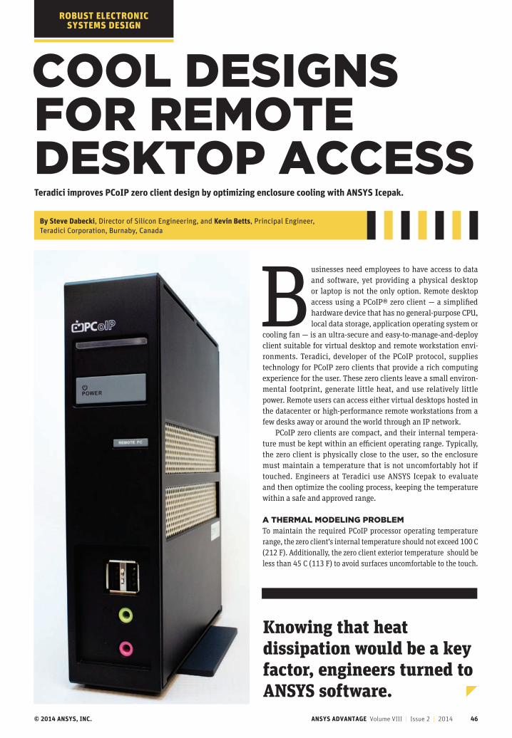
© 2014 ANSYS, INC. ANSYS ADVANTAGE Volume VIII | Issue 2 | 2014 46
COOL DESIGNS FOR REMOTE DESKTOP ACCESSTeradici improves PCoIP zero client design by optimizing enclosure cooling with ANSYS Icepak.
By Steve Dabecki, Director of Silicon Engineering, and Kevin Betts, Principal Engineer, Teradici Corporation, Burnaby, Canada
ROBUST ELECTRONIC SYSTEMS DESIGN
Businesses need employees to have access to data and software, yet providing a physical desktop or laptop is not the only option. Remote desktop access using a PCoIP® zero client ― a simplified hardware device that has no general-purpose CPU, local data storage, application operating system or
cooling fan — is an ultra-secure and easy-to-manage-and-deploy client suitable for virtual desktop and remote workstation envi-ronments. Teradici, developer of the PCoIP protocol, supplies technology for PCoIP zero clients that provide a rich computing experience for the user. These zero clients leave a small environ-mental footprint, generate little heat, and use relatively little power. Remote users can access either virtual desktops hosted in the datacenter or high-performance remote workstations from a few desks away or around the world through an IP network.
PCoIP zero clients are compact, and their internal tempera-ture must be kept within an efficient operating range. Typically, the zero client is physically close to the user, so the enclosure must maintain a temperature that is not uncomfortably hot if touched. Engineers at Teradici use ANSYS Icepak to evaluate and then optimize the cooling process, keeping the temperature within a safe and approved range.
A THERMAL MODELING PROBLEMTo maintain the required PCoIP processor operating temperature range, the zero client’s internal temperature should not exceed 100 C (212 F). Additionally, the zero client exterior temperature should be less than 45 C (113 F) to avoid surfaces uncomfortable to the touch.
Knowing that heat dissipation would be a key factor, engineers turned to ANSYS software.
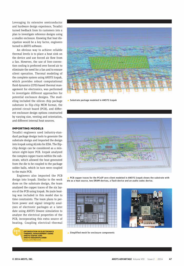
© 2014 ANSYS, INC. ANSYS ADVANTAGE Volume VIII | Issue 2 | 2014 47
Leveraging its extensive semiconductor and hardware design experience, Teradici turned feedback from its customers into a plan to investigate reference designs using a smaller enclosure. Knowing that heat dis-sipation would be a key factor, engineers turned to ANSYS software.
An obvious way to achieve reliable thermal levels is to place a heat sink on the device and use forced air flow from a fan. However, the use of free-convec-tion cooling is preferred over forced air to eliminate the need for a fan and to ensure silent operation. Thermal modeling of the complete system using ANSYS Icepak, which provides robust computational fluid dynamics (CFD)-based thermal man-agement for electronics, was performed to investigate different approaches for potential enclosure designs. The mod-eling included the silicon chip package substrate in flip-chip MCM format, the printed circuit board (PCB), and differ-ent enclosure design options constructed by varying size, venting and orientation, and different internal heat sources.
IMPORTING MODELSTeradici engineers used industry-stan-dard package design tools to generate the substrate design and imported the design into Icepak using ALinks for EDA. The flip-chip design can be considered as a min-iature eight-layer PCB. Icepak analyzed the complex copper traces within the sub-strate, which allowed the heat generated from the die to be coupled to the package solder balls, which in turn were coupled to the main PCB.
Engineers also imported the PCB design into Icepak. Similar to the work done on the substrate design, the team analyzed the copper traces of the six lay-ers of the PCB using Icepak. No joule heat-ing was included in this model due to time constraints. The team plans to per-form power and signal integrity anal-yses of electronic packages at a later date using ANSYS SIwave simulation to analyze the electrical properties of the PCB, incorporating this extra source of heating. Coupling electrical–thermal
� Substrate package modeled in ANSYS Icepak
� PCB copper traces for the PCoIP zero client modeled in ANSYS Icepak shows the substrate with die as a heat source, two DRAM devices, a flash device and an audio codec device.
� Simplified mesh for enclosure components OPTIMIZATION IN ELECTRONICS THERMAL MANAGEMENT USING ANSYS ICEPAK AND ANSYS DESIGNXPLORERansys.com/82cool2
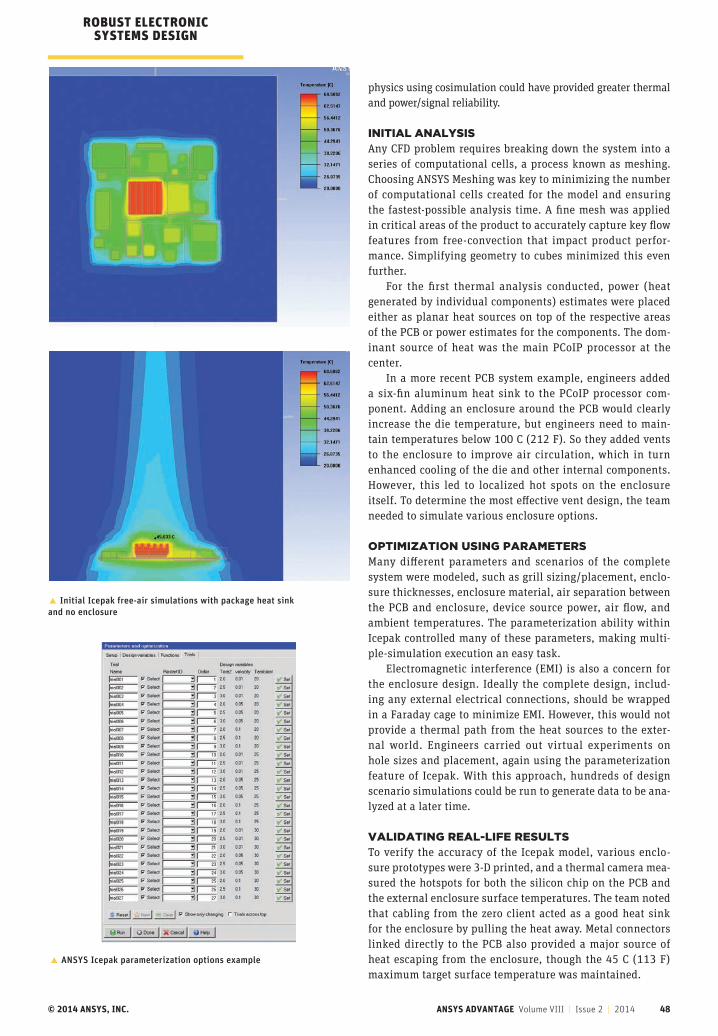
© 2014 ANSYS, INC. ANSYS ADVANTAGE Volume VIII | Issue 2 | 2014 48
ROBUST ELECTRONIC SYSTEMS DESIGN
� Initial Icepak free-air simulations with package heat sink and no enclosure
physics using cosimulation could have provided greater thermal and power/signal reliability.
INITIAL ANALYSISAny CFD problem requires breaking down the system into a series of computational cells, a process known as meshing. Choosing ANSYS Meshing was key to minimizing the number of computational cells created for the model and ensuring the fastest-possible analysis time. A fine mesh was applied in critical areas of the product to accurately capture key flow features from free-convection that impact product perfor-mance. Simplifying geometry to cubes minimized this even further.
For the first thermal analysis conducted, power (heat generated by individual components) estimates were placed either as planar heat sources on top of the respective areas of the PCB or power estimates for the components. The dom-inant source of heat was the main PCoIP processor at the center.
In a more recent PCB system example, engineers added a six-fin aluminum heat sink to the PCoIP processor com-ponent. Adding an enclosure around the PCB would clearly increase the die temperature, but engineers need to main-tain temperatures below 100 C (212 F). So they added vents to the enclosure to improve air circulation, which in turn enhanced cooling of the die and other internal components. However, this led to localized hot spots on the enclosure itself. To determine the most effective vent design, the team needed to simulate various enclosure options.
OPTIMIZATION USING PARAMETERS Many different parameters and scenarios of the complete system were modeled, such as grill sizing/placement, enclo-sure thicknesses, enclosure material, air separation between the PCB and enclosure, device source power, air flow, and ambient temperatures. The parameterization ability within Icepak controlled many of these parameters, making multi-ple-simulation execution an easy task.
Electromagnetic interference (EMI) is also a concern for the enclosure design. Ideally the complete design, includ-ing any external electrical connections, should be wrapped in a Faraday cage to minimize EMI. However, this would not provide a thermal path from the heat sources to the exter-nal world. Engineers carried out virtual experiments on hole sizes and placement, again using the parameterization feature of Icepak. With this approach, hundreds of design scenario simulations could be run to generate data to be ana-lyzed at a later time.
VALIDATING REAL-LIFE RESULTSTo verify the accuracy of the Icepak model, various enclo-sure prototypes were 3-D printed, and a thermal camera mea-sured the hotspots for both the silicon chip on the PCB and the external enclosure surface temperatures. The team noted that cabling from the zero client acted as a good heat sink for the enclosure by pulling the heat away. Metal connectors linked directly to the PCB also provided a major source of heat escaping from the enclosure, though the 45 C (113 F) maximum target surface temperature was maintained.
� ANSYS Icepak parameterization options example
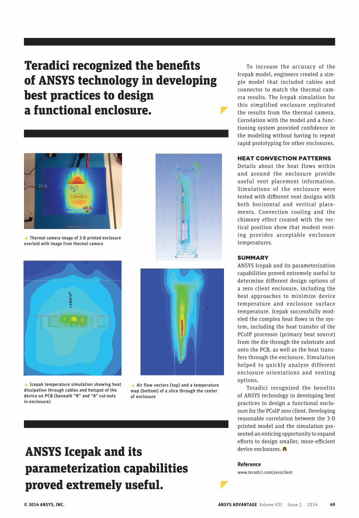
© 2014 ANSYS, INC. ANSYS ADVANTAGE Volume VIII | Issue 2 | 2014 49
To increase the accuracy of the Icepak model, engineers created a sim-ple model that included cables and connector to match the thermal cam-era results. The Icepak simulation for this simplified enclosure replicated the results from the thermal camera. Correlation with the model and a func-tioning system provided confidence in the modeling without having to repeat rapid prototyping for other enclosures.
HEAT CONVECTION PATTERNSDetails about the heat flows within and around the enclosure provide useful vent placement information. Simulations of the enclosure were tested with different vent designs with both horizontal and vertical place-ments. Convection cooling and the chimney effect created with the ver-tical position show that modest vent-ing provides acceptable enclosure temperatures.
SUMMARYANSYS Icepak and its parameterization capabilities proved extremely useful to determine different design options of a zero client enclosure, including the best approaches to minimize device temperature and enclosure surface temperature. Icepak successfully mod-eled the complex heat flows in the sys-tem, including the heat transfer of the PCoIP processor (primary heat source) from the die through the substrate and onto the PCB, as well as the heat trans-fers through the enclosure. Simulation helped to quickly analyze different enclosure orientations and venting options.
Teradici recognized the benefits of ANSYS technology in developing best practices to design a functional enclo-sure for the PCoIP zero client. Developing reasonable correlation between the 3-D printed model and the simulation pre-sented an enticing opportunity to expand efforts to design smaller, more-efficient device enclosures.
Reference www.teradici.com/zeroclient
Teradici recognized the benefits of ANSYS technology in developing best practices to design a functional enclosure.
� Thermal camera image of 3-D printed enclosure overlaid with image from thermal camera
� Icepak temperature simulation showing heat dissipation through cables and hotspot of the device on PCB (beneath “R” and “A” cut-outs in enclosure)
� Air flow vectors (top) and a temperature map (bottom) of a slice through the center of enclosure
ANSYS Icepak and its parameterization capabilities proved extremely useful.
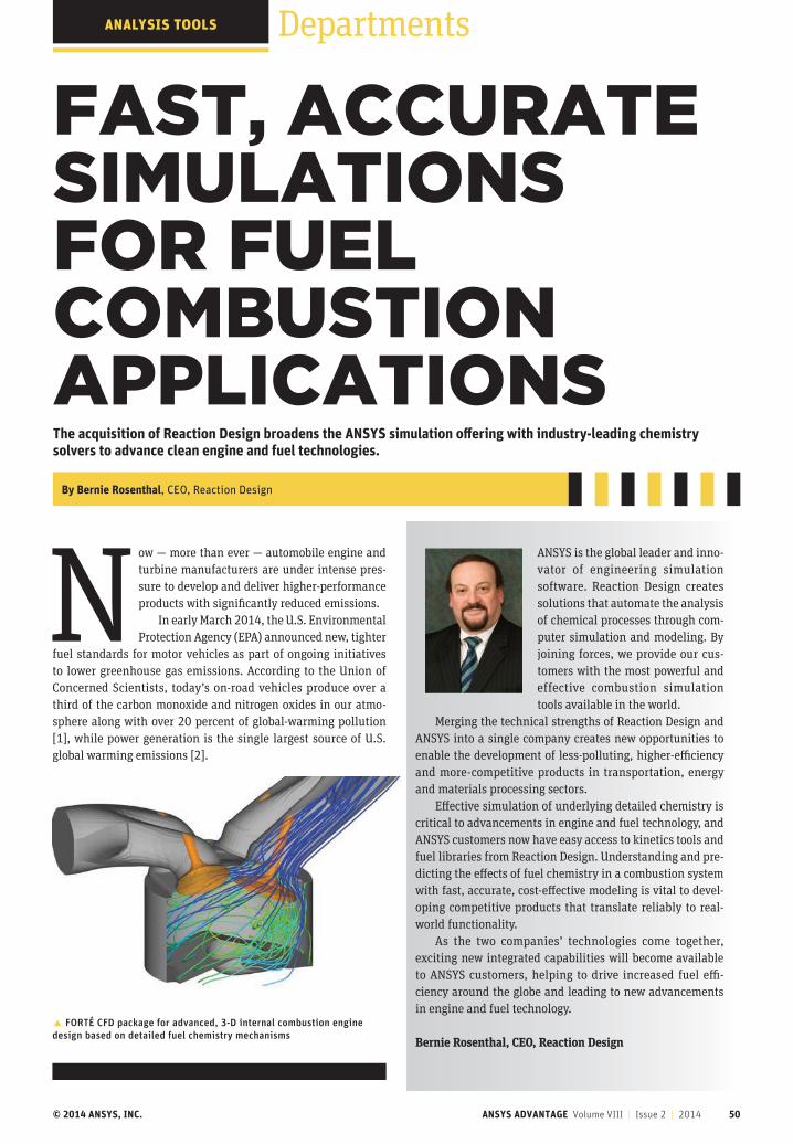
© 2014 ANSYS, INC. ANSYS ADVANTAGE Volume VIII | Issue 2 | 2014 50
Now — more than ever — automobile engine and turbine manufacturers are under intense pres-sure to develop and deliver higher-performance products with significantly reduced emissions.
In early March 2014, the U.S. Environmental Protection Agency (EPA) announced new, tighter
fuel standards for motor vehicles as part of ongoing initiatives to lower greenhouse gas emissions. According to the Union of Concerned Scientists, today’s on-road vehicles produce over a third of the carbon monoxide and nitrogen oxides in our atmo-sphere along with over 20 percent of global-warming pollution [1], while power generation is the single largest source of U.S. global warming emissions [2].
DepartmentsANALYSIS TOOLS
FAST, ACCURATE SIMULATIONS FOR FUEL COMBUSTION APPLICATIONSThe acquisition of Reaction Design broadens the ANSYS simulation offering with industry-leading chemistry solvers to advance clean engine and fuel technologies.
By Bernie Rosenthal, CEO, Reaction Design
ANSYS is the global leader and inno-vator of engineering simulation software. Reaction Design creates solutions that automate the analysis of chemical processes through com-puter simulation and modeling. By joining forces, we provide our cus-tomers with the most powerful and effective combustion simulation tools available in the world.
Merging the technical strengths of Reaction Design and ANSYS into a single company creates new opportunities to enable the development of less-polluting, higher-efficiency and more-competitive products in transportation, energy and materials processing sectors.
Effective simulation of underlying detailed chemistry is critical to advancements in engine and fuel technology, and ANSYS customers now have easy access to kinetics tools and fuel libraries from Reaction Design. Understanding and pre-dicting the effects of fuel chemistry in a combustion system with fast, accurate, cost-effective modeling is vital to devel-oping competitive products that translate reliably to real-world functionality.
As the two companies’ technologies come together, exciting new integrated capabilities will become available to ANSYS customers, helping to drive increased fuel effi-ciency around the globe and leading to new advancements in engine and fuel technology.
Bernie Rosenthal, CEO, Reaction Design� FORTÉ CFD package for advanced, 3-D internal combustion engine design based on detailed fuel chemistry mechanisms
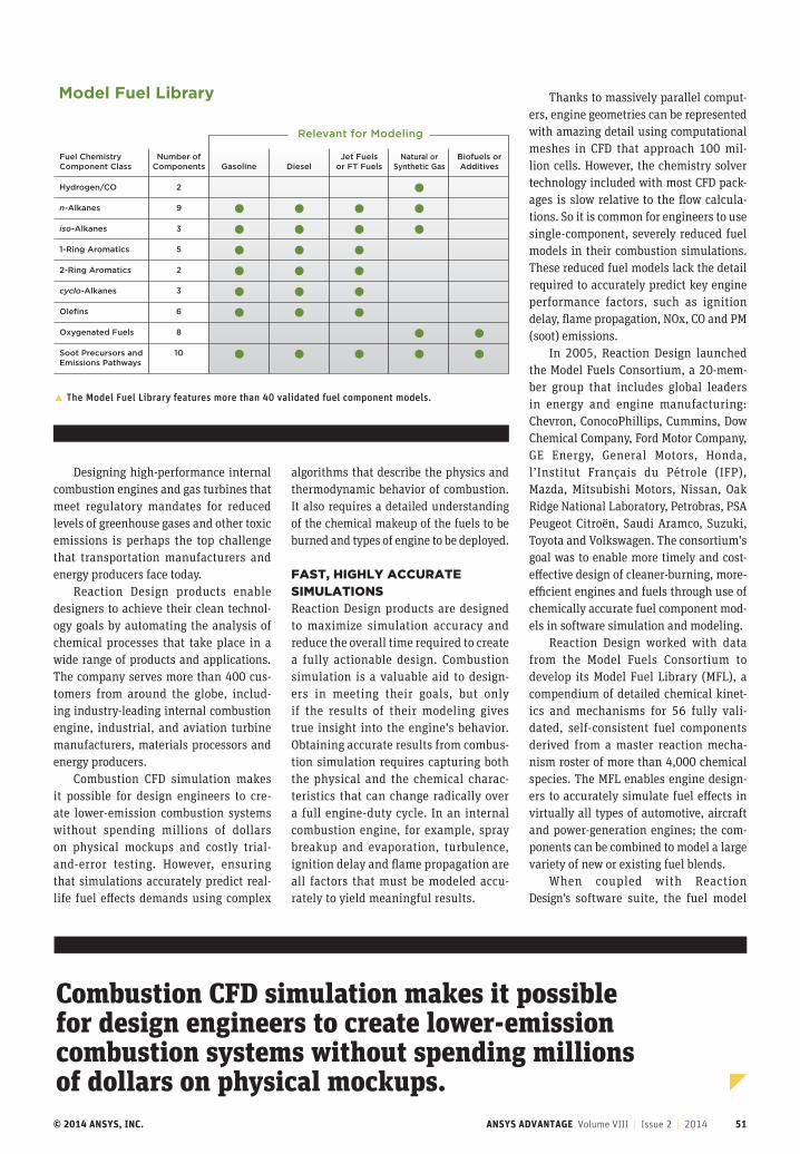
© 2014 ANSYS, INC. ANSYS ADVANTAGE Volume VIII | Issue 2 | 2014 51
Designing high-performance internal combustion engines and gas turbines that meet regulatory mandates for reduced levels of greenhouse gases and other toxic emissions is perhaps the top challenge that transportation manufacturers and energy producers face today.
Reaction Design products enable designers to achieve their clean technol-ogy goals by automating the analysis of chemical processes that take place in a wide range of products and applications. The company serves more than 400 cus-tomers from around the globe, includ-ing industry-leading internal combustion engine, industrial, and aviation turbine manufacturers, materials processors and energy producers.
Combustion CFD simulation makes it possible for design engineers to cre-ate lower-emission combustion systems without spending millions of dollars on physical mockups and costly trial-and-error testing. However, ensuring that simulations accurately predict real-life fuel effects demands using complex
Fuel ChemistryComponent Class
Hydrogen/CO
n-Alkanes
iso-Alkanes
1-Ring Aromatics
2-Ring Aromatics
cyclo-Alkanes
Olefins
Oxygenated Fuels
Soot Precursors andEmissions Pathways
Number ofComponents
2
9
3
5
2
3
6
8
10
Gasoline DieselJet Fuels
or FT FuelsNatural or
Synthetic GasBiofuels orAdditives
Model Fuel Library
Relevant for Modeling
� The Model Fuel Library features more than 40 validated fuel component models.
algorithms that describe the physics and thermodynamic behavior of combustion. It also requires a detailed understanding of the chemical makeup of the fuels to be burned and types of engine to be deployed.
FAST, HIGHLY ACCURATE SIMULATIONSReaction Design products are designed to maximize simulation accuracy and reduce the overall time required to create a fully actionable design. Combustion simulation is a valuable aid to design-ers in meeting their goals, but only if the results of their modeling gives true insight into the engine’s behavior. Obtaining accurate results from combus-tion simulation requires capturing both the physical and the chemical charac-teristics that can change radically over a full engine-duty cycle. In an internal combustion engine, for example, spray breakup and evaporation, turbulence, ignition delay and flame propagation are all factors that must be modeled accu-rately to yield meaningful results.
Thanks to massively parallel comput-ers, engine geometries can be represented with amazing detail using computational meshes in CFD that approach 100 mil-lion cells. However, the chemistry solver technology included with most CFD pack-ages is slow relative to the flow calcula-tions. So it is common for engineers to use single-component, severely reduced fuel models in their combustion simulations. These reduced fuel models lack the detail required to accurately predict key engine performance factors, such as ignition delay, flame propagation, NOx, CO and PM (soot) emissions.
In 2005, Reaction Design launched the Model Fuels Consortium, a 20-mem-ber group that includes global leaders in energy and engine manufacturing: Chevron, ConocoPhillips, Cummins, Dow Chemical Company, Ford Motor Company, GE Energy, General Motors, Honda, l’Institut Français du Pétrole (IFP), Mazda, Mitsubishi Motors, Nissan, Oak Ridge National Laboratory, Petrobras, PSA Peugeot Citroën, Saudi Aramco, Suzuki, Toyota and Volkswagen. The consortium’s goal was to enable more timely and cost-effective design of cleaner-burning, more-efficient engines and fuels through use of chemically accurate fuel component mod-els in software simulation and modeling.
Reaction Design worked with data from the Model Fuels Consortium to develop its Model Fuel Library (MFL), a compendium of detailed chemical kinet-ics and mechanisms for 56 fully vali-dated, self-consistent fuel components derived from a master reaction mecha-nism roster of more than 4,000 chemical species. The MFL enables engine design-ers to accurately simulate fuel effects in virtually all types of automotive, aircraft and power-generation engines; the com-ponents can be combined to model a large variety of new or existing fuel blends.
When coupled with Reaction Design’s software suite, the fuel model
Combustion CFD simulation makes it possible for design engineers to create lower-emission combustion systems without spending millions of dollars on physical mockups.
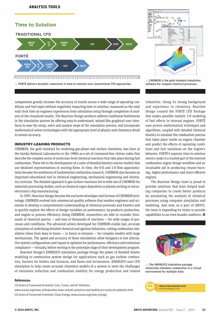
© 2014 ANSYS, INC. ANSYS ADVANTAGE Volume VIII | Issue 2 | 2014 52
industries. Using its strong background and experience in chemistry, Reaction Design created the FORTÉ CFD Package that makes possible realistic 3-D modeling of fuel effects in internal engines. FORTÉ uses proven mathematical techniques and algorithms, coupled with detailed chemical kinetics to simulate the combustion process that takes place inside an engine chamber and predict the effects of operating condi-tions and fuel variations on the engine’s behavior. FORTÉ’s superior time-to-solution metrics make it a trusted part of the internal combustion engine design workflow and an invaluable aid in producing cleaner-burn-ing, higher-performance and more-efficient engines.
The Reaction Design team is proud to provide solutions that have helped lead-ing companies to create better products by automating the analysis of chemical processes using computer simulation and modeling. And now, as a part of ANSYS, the team is expanding its vision to provide capabilities to an even broader audience.
components greatly increase the accuracy of results across a wide range of operating con-ditions and fuel types without negatively impacting time to solution, measured as the total wall clock time an engineer experiences from simulation setup through completion of anal-ysis of the visualized results. The Reaction Design products address traditional bottlenecks in the simulation process by offering easy-to-understand, wizard-like graphical user inter-faces to ease the setup, solve and analyze steps of the simulation process, and incorporate mathematical solver technologies with the appropriate level of physics and chemistry detail to ensure accuracy.
INDUSTRY-LEADING PRODUCTSCHEMKIN, the gold standard for modeling gas-phase and surface chemistry, was born at the Sandia National Laboratories in the 1980s as a set of command-line–driven codes that describe the complex series of molecular-level chemical reactions that take place during fuel combustion. These led to the development of a suite of detailed-kinetics reactor models that use idealized representations of reacting flows. In time, the 0-D and 1-D flow approxima-tions became the workhorse of fundamental combustion research. CHEMKIN also became an important educational tool in chemical engineering, mechanical engineering and chemis-try curricula. The detailed approach to gas-surface reactions led to wide use of CHEMKIN for materials processing studies, such as chemical vapor deposition or plasma etching in micro-electronics chip manufacturing.
In 1997, Reaction Design became the exclusive developer and licensor of CHEMKIN tech-nology. CHEMKIN evolved into commercial-quality software that enables engineers and sci-entists to develop a comprehensive understanding of chemical processes and kinetics and to quickly explore the effects of design variables on performance, by-products production, and engine or process efficiency. Using CHEMKIN, researchers are able to consider thou-sands of chemical species — and tens of thousands of reactions — for wide ranges of pro-cesses and conditions. The advanced solvers developed for CHEMKIN enable fast, accurate simulation of underlying detailed chemical and ignition behaviors, cutting combustion sim-ulation times from days to hours — or hours to minutes — for complex models with large mechanisms. The speed and accuracy of these simulations allow designers to test alterna-tive system configurations and inputs to optimize for performance, efficiency and emissions compliance — virtually, before moving to the prototype stage of their development program.
Reaction Design’s ENERGICO simulation package brings the power of detailed kinetic modeling to combustion system design for applications such as gas turbine combus-tors, burners for boilers and furnaces, and flares and incinerators. ENERGICO uses CFD simulation to help create accurate chemistry models of a system to meet the challenges of emissions reduction and combustion stability for energy production and related
Time to Solution
TRADITIONAL CFD
FORTE
GENERATEMESH
SET-UP
CALIBRATESPRAY SOLVE EXPORT ANALYZE
GENERATEMESH
SET-UP
CALIBRATESPRAY SOLVE ANALYZE
´
� FORTÉ delivers dramatic reductions in time to solution over conventional CFD approaches.
� The ENERGICO simulation package chemically simulates combustion in a virtual environment for multiple fuels.
� CHEMKIN is the gold standard simulation software for complex chemical processes.
ANALYSIS TOOLS
References [1] Union of Concerned Scientists: Cars, Trucks, and Air Pollution,
www.ucsusa.org/clean_vehicles/why-clean-cars/air-pollution-and-health/cars-trucks-air-pollution.html
[2] Union of Concerned Scientists: Clean Energy, www.ucsusa.org/clean_energy/
REACTION DESIGN SITEreactiondesign.com
© 2014 ANSYS, INC. ANSYS ADVANTAGE Volume VIII | Issue 2 | 2014 53
Improve reliability. Avoid unplanned downtime.
A TEAM Industrial Services Company
www.QuestIntegrity.com/SFFS
Email: [email protected]
Signal™ Fitness-for-Service (FFS) is a user-friendly, intuitive software tool for performing fitness-for-purpose and fracture mechanics analyses on fixed and rotating equipment. It gives engineers the ability to reduce operational and safety risks associated with equipment through its comprehensive adherence to industry standards such as API 579.
Signal FFS Features
• Adheres to API 579/ASME-FFS standards
• Enables rapid Level 1 and 2 FFS assessments
• Includes advanced fracture assessment capabilities
• Provides quantitative support for critical decisionmaking
Signal FFS Benefits
• Reduces operational and safety risk with quickLevel 1, 2, and 3 assessments
• Improves profitability by improving plant reliabilityand avoiding costly unplanned downtime
• Optimizes equipment yields based on remaining lifeestimates using aggressive operating conditions
ansys.com/social@ansys
JOIN THE SIMULATION CONVERSATION

© 2014 ANSYS, INC. ANSYS ADVANTAGE Volume VIII | Issue 2 | 2014 54
In the fast-paced consumer electronics market, companies are under pressure to get their products onto store shelves ahead of the competition. To address increased product complexities while also meeting shortened design cycle times, a proven approach is to add simulation software to the R&D process. Introducing analysis tools enables a
design engineer to generate a model as a virtual representation of a physical geometry and then use physics-based calculations to refine and optimize a product. This can be much faster than the historical method of trial-and-error prototyping. Consequently, leading organizations have adopted simulation processes for many engineering disciplines. Traditionally, engineers use flu-ids, thermal, structural or electronic analysis tools separately to design a specific aspect of a product. By considering the different physics in isolation, however, engineers are unable to account for all the effects designs may impose on other disciplines or other
functionality of the overall system-level design. ANSYS capabilities allow engineers to gain in-depth under-
standing of particular cross-physics phenomena and how they relate to one another. An engineer concerned with electrical power delivery can simulate how much loss he or she is see-ing within a circuit board by accounting for changes in mate-rial resistivity due to joule heating of the conductors. Through ANSYS Workbench, industry-leading structural, thermal, fluids and electromagnetic field solvers are brought together to enable true multiphysics simulations. Geometry can be shared automat-ically between these solvers, since design changes made for one solver may also have an impact on the predictions from another solver being used to model the same or an adjacent section of a design. Using the shared geometry, a Workbench project can be set up so that different physics domain experts can each con-figure the proper single-physics simulation for their particular
ANALYSIS TOOLS
A FOUNDATION FOR COLLABORATIONMultiphysics simulation in ANSYS Workbench powers system-level analysis and helps shorten design cycles.
By Guy Barnes, Lead Technical Services Engineer; Zoran Dragojlovic, Technical Services Engineer; and Jared Harvest, Senior Technical Services Engineer, ANSYS
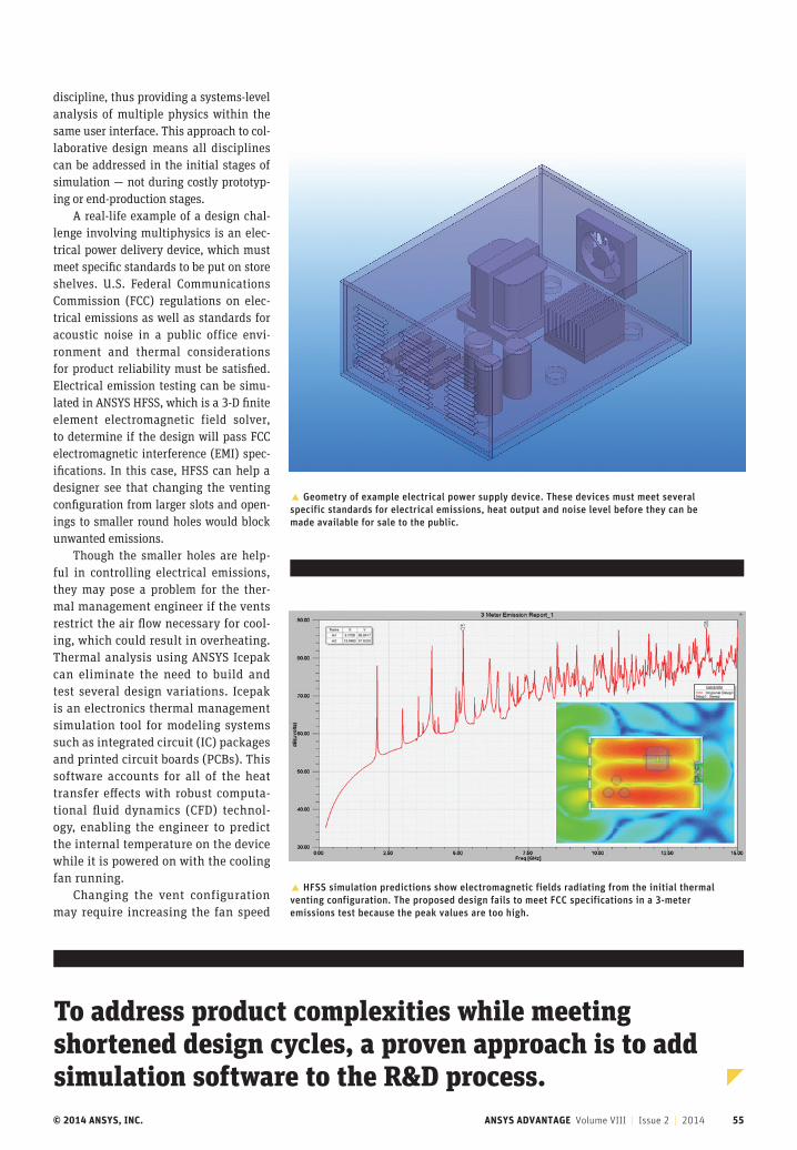
© 2014 ANSYS, INC. ANSYS ADVANTAGE Volume VIII | Issue 2 | 2014 55
discipline, thus providing a systems-level analysis of multiple physics within the same user interface. This approach to col-laborative design means all disciplines can be addressed in the initial stages of simulation — not during costly prototyp-ing or end-production stages.
A real-life example of a design chal-lenge involving multiphysics is an elec-trical power delivery device, which must meet specific standards to be put on store shelves. U.S. Federal Communications Commission (FCC) regulations on elec-trical emissions as well as standards for acoustic noise in a public office envi-ronment and thermal considerations for product reliability must be satisfied. Electrical emission testing can be simu-lated in ANSYS HFSS, which is a 3-D finite element electromagnetic field solver, to determine if the design will pass FCC electromagnetic interference (EMI) spec-ifications. In this case, HFSS can help a designer see that changing the venting configuration from larger slots and open-ings to smaller round holes would block unwanted emissions.
Though the smaller holes are help-ful in controlling electrical emissions, they may pose a problem for the ther-mal management engineer if the vents restrict the air flow necessary for cool-ing, which could result in overheating. Thermal analysis using ANSYS Icepak can eliminate the need to build and test several design variations. Icepak is an electronics thermal management simulation tool for modeling systems such as integrated circuit (IC) packages and printed circuit boards (PCBs). This software accounts for all of the heat transfer effects with robust computa-tional fluid dynamics (CFD) technol-ogy, enabling the engineer to predict the internal temperature on the device while it is powered on with the cooling fan running.
Changing the vent configuration may require increasing the fan speed
� Geometry of example electrical power supply device. These devices must meet several specific standards for electrical emissions, heat output and noise level before they can be made available for sale to the public.
� HFSS simulation predictions show electromagnetic fields radiating from the initial thermal venting configuration. The proposed design fails to meet FCC specifications in a 3-meter emissions test because the peak values are too high.
To address product complexities while meeting shortened design cycles, a proven approach is to add simulation software to the R&D process.
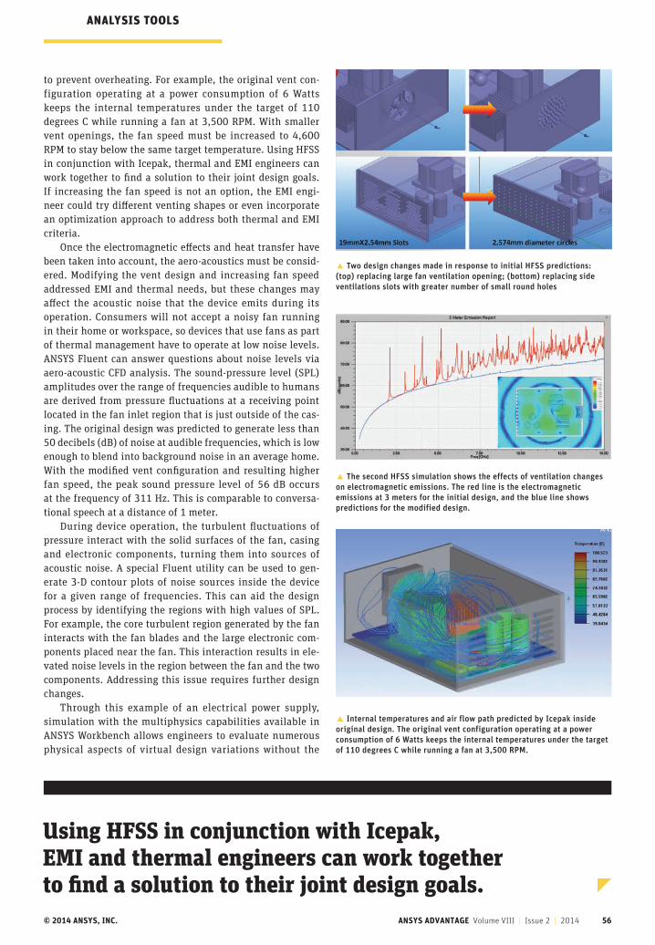
© 2014 ANSYS, INC. ANSYS ADVANTAGE Volume VIII | Issue 2 | 2014 56
Using HFSS in conjunction with Icepak, EMI and thermal engineers can work together to find a solution to their joint design goals.
to prevent overheating. For example, the original vent con-figuration operating at a power consumption of 6 Watts keeps the internal temperatures under the target of 110 degrees C while running a fan at 3,500 RPM. With smaller vent openings, the fan speed must be increased to 4,600 RPM to stay below the same target temperature. Using HFSS in conjunction with Icepak, thermal and EMI engineers can work together to find a solution to their joint design goals. If increasing the fan speed is not an option, the EMI engi-neer could try different venting shapes or even incorporate an optimization approach to address both thermal and EMI criteria.
Once the electromagnetic effects and heat transfer have been taken into account, the aero-acoustics must be consid-ered. Modifying the vent design and increasing fan speed addressed EMI and thermal needs, but these changes may affect the acoustic noise that the device emits during its operation. Consumers will not accept a noisy fan running in their home or workspace, so devices that use fans as part of thermal management have to operate at low noise levels. ANSYS Fluent can answer questions about noise levels via aero-acoustic CFD analysis. The sound-pressure level (SPL) amplitudes over the range of frequencies audible to humans are derived from pressure fluctuations at a receiving point located in the fan inlet region that is just outside of the cas-ing. The original design was predicted to generate less than 50 decibels (dB) of noise at audible frequencies, which is low enough to blend into background noise in an average home. With the modified vent configuration and resulting higher fan speed, the peak sound pressure level of 56 dB occurs at the frequency of 311 Hz. This is comparable to conversa-tional speech at a distance of 1 meter.
During device operation, the turbulent fluctuations of pressure interact with the solid surfaces of the fan, casing and electronic components, turning them into sources of acoustic noise. A special Fluent utility can be used to gen-erate 3-D contour plots of noise sources inside the device for a given range of frequencies. This can aid the design process by identifying the regions with high values of SPL. For example, the core turbulent region generated by the fan interacts with the fan blades and the large electronic com-ponents placed near the fan. This interaction results in ele-vated noise levels in the region between the fan and the two components. Addressing this issue requires further design changes.
Through this example of an electrical power supply, simulation with the multiphysics capabilities available in ANSYS Workbench allows engineers to evaluate numerous physical aspects of virtual design variations without the
� The second HFSS simulation shows the effects of ventilation changes on electromagnetic emissions. The red line is the electromagnetic emissions at 3 meters for the initial design, and the blue line shows predictions for the modified design.
� Two design changes made in response to initial HFSS predictions: (top) replacing large fan ventilation opening; (bottom) replacing side ventilations slots with greater number of small round holes
� Internal temperatures and air flow path predicted by Icepak inside original design. The original vent configuration operating at a power consumption of 6 Watts keeps the internal temperatures under the target of 110 degrees C while running a fan at 3,500 RPM.
ANALYSIS TOOLS
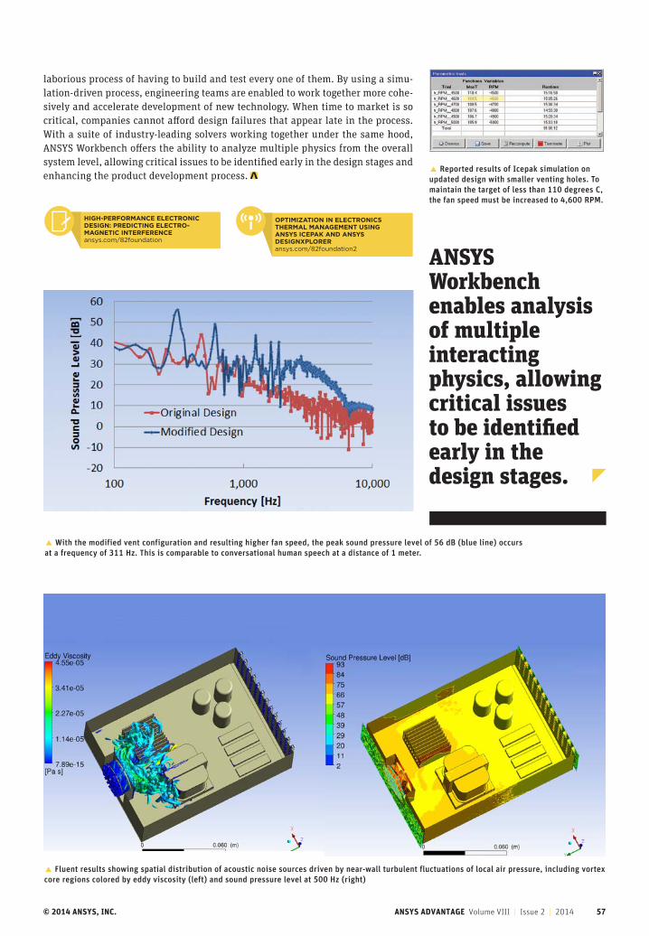
© 2014 ANSYS, INC. ANSYS ADVANTAGE Volume VIII | Issue 2 | 2014 57
laborious process of having to build and test every one of them. By using a simu-lation-driven process, engineering teams are enabled to work together more cohe-sively and accelerate development of new technology. When time to market is so critical, companies cannot afford design failures that appear late in the process. With a suite of industry-leading solvers working together under the same hood, ANSYS Workbench offers the ability to analyze multiple physics from the overall system level, allowing critical issues to be identified early in the design stages and enhancing the product development process. � Reported results of Icepak simulation on
updated design with smaller venting holes. To maintain the target of less than 110 degrees C, the fan speed must be increased to 4,600 RPM.
� With the modified vent configuration and resulting higher fan speed, the peak sound pressure level of 56 dB (blue line) occurs at a frequency of 311 Hz. This is comparable to conversational human speech at a distance of 1 meter.
� Fluent results showing spatial distribution of acoustic noise sources driven by near-wall turbulent fluctuations of local air pressure, including vortex core regions colored by eddy viscosity (left) and sound pressure level at 500 Hz (right)
ANSYS Workbench enables analysis of multiple interacting physics, allowing critical issues to be identified early in the design stages.
HIGH-PERFORMANCE ELECTRONIC DESIGN: PREDICTING ELECTROMAGNETIC INTERFERENCE
ansys.com
HIGH-PERFORMANCE ELECTRONIC DESIGN: PREDICTING ELECTRO- MAGNETIC INTERFERENCEansys.com/82foundation
OPTIMIZATION IN ELECTRONICS THERMAL MANAGEMENT USING ANSYS ICEPAK AND ANSYS DESIGNXPLORERansys.com/82foundation2
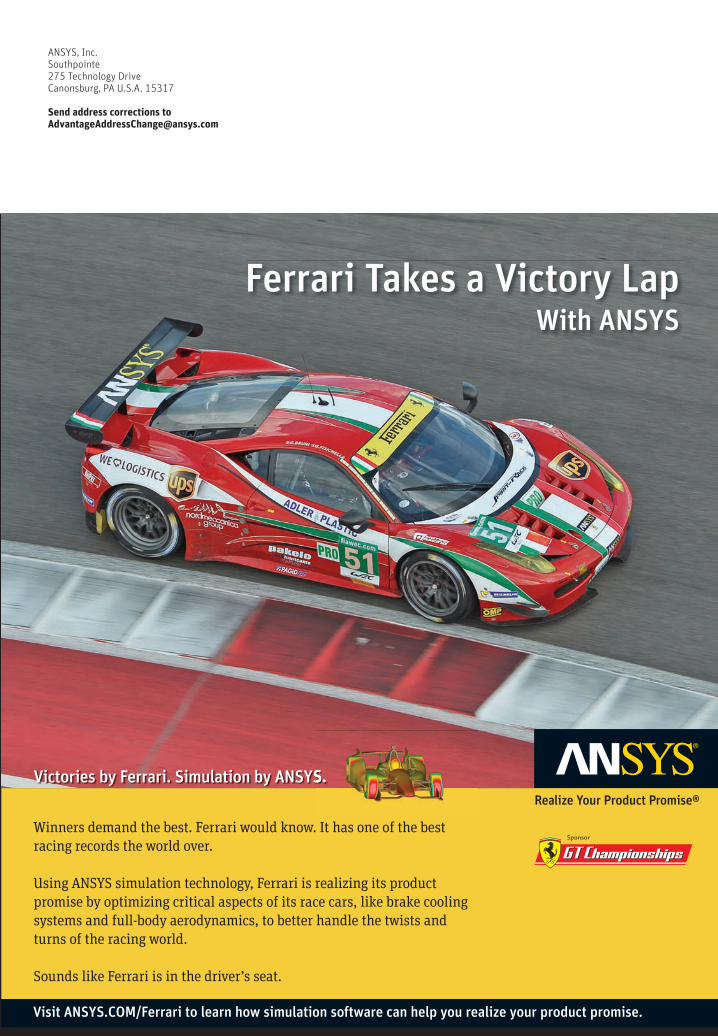
© 2014 ANSYS, INC. ANSYS ADVANTAGE Volume VIII | Issue 1 | 2014 58
Realize Your Product Promise®
Ferrari Takes a Victory Lap With ANSYS
Winners demand the best. Ferrari would know. It has one of the best racing records the world over.
Using ANSYS simulation technology, Ferrari is realizing its product promise by optimizing critical aspects of its race cars, like brake cooling systems and full-body aerodynamics, to better handle the twists and turns of the racing world.
Sounds like Ferrari is in the driver’s seat.
Victories by Ferrari. Simulation by ANSYS.Victories by Ferrari. Simulation by ANSYS.Victories by Ferrari. Simulation by ANSYS.
Visit ANSYS.COM/Ferrari to learn how simulation software can help you realize your product promise.
ANSYS, Inc.Southpointe275 Technology DriveCanonsburg, PA U.S.A. 15317
Send address corrections [email protected]