
Ansinema c29!5!2015 Watermarked
19
ANSI/NEMA C29.5-2015 American National Standard for Wet-Process Porcelain Insulators— Low- and Medium-Voltage Types Secretariat: National Electrical Manufacturers Association Approved: July 30, 2015 Published: September 22, 2015 American National Standards Institute, Inc.
description
ANSI Standard for Insulators
Transcript of Ansinema c29!5!2015 Watermarked

ANSI/NEMA C29.5-2015
American National Standard for Wet-Process Porcelain Insulators—
Low- and Medium-Voltage Types
Secretariat:
National Electrical Manufacturers Association Approved: July 30, 2015 Published: September 22, 2015
American National Standards Institute, Inc.
© 2015 National Electrical Manufacturers Association
NOTICE AND DISCLAIMER The information in this publication was considered technically sound by the consensus of persons engaged in the development and approval of the document at the time it was developed. Consensus does not necessarily mean that there is unanimous agreement among every person participating in the development of this document.
American National Standards Institute (ANSI) standards and guideline publications, of which the document contained herein is one, are developed through a voluntary consensus standards development process. This process brings together volunteers and/or seeks out the views of persons who have an interest in the topic covered by this publication. While NEMA administers the process and establishes rules to promote fairness in the development of consensus, it does not write the document and it does not independently test, evaluate, or verify the accuracy or completeness of any information or the soundness of any judgments contained in its standards and guideline publications. NEMA disclaims liability for any personal injury, property, or other damages of any nature whatsoever, whether special, indirect, consequential, or compensatory, directly or indirectly resulting from the publication, use of, application, or reliance on this document. NEMA disclaims and makes no guaranty or warranty, express or implied, as to the accuracy or completeness of any information published herein, and disclaims and makes no warranty that the information in this document will fulfill any of your particular purposes or needs. NEMA does not undertake to guarantee the performance of any individual manufacturer or seller’s products or services by virtue of this standard or guide. In publishing and making this document available, NEMA is not undertaking to render professional or other services for or on behalf of any person or entity, nor is NEMA undertaking to perform any duty owed by any person or entity to someone else. Anyone using this document should rely on his or her own independent judgment or, as appropriate, seek the advice of a competent professional in determining the exercise of reasonable care in any given circumstances. Information and other standards on the topic covered by this publication may be available from other sources, which the user may wish to consult for additional views or information not covered by this publication. NEMA has no power, nor does it undertake to police or enforce compliance with the contents of this document. NEMA does not certify, test, or inspect products, designs, or installations for safety or health purposes. Any certification or other statement of compliance with any health- or safety-related information in this document shall not be attributable to NEMA and is solely the responsibility of the certifier or maker of the statement.
ANSI/NEMA C29.5-2015 Page i
AMERICAN
NATIONAL
STANDARD
Approval of an American National Standard requires verification by ANSI that the requirements for due process, consensus, and other criteria for approval have been met by the standards developer.
Consensus is established when, in the judgment of the ANSI Board of Standards Review, substantial agreement has been reached by directly and materially affected interests. Substantial agreement means much more than a simple majority, but not necessarily unanimity. Consensus requires that all views and objections be considered, and that a concerted effort be made toward their resolution.
The use of American National Standards is completely voluntary; their existence does not in any respect preclude anyone, whether he has approved the standards or not, from manufacturing, marketing, purchasing, or using products, processes, or procedures not conforming to the standards.
The American National Standards Institute does not develop standards and will in no circumstances give an interpretation of any American National Standard. Moreover, no person shall have the right or authority to issue an interpretation of an American National Standard in the name of the American National Standards Institute. Requests for interpretations should be addressed to the secretariat or sponsor whose name appears on the title page of this standard.
CAUTION NOTICE: This American National Standard may be revised or withdrawn at any time. The procedures of the American National Standards Institute require that action be taken periodically to reaffirm, revise, or withdraw this standard. Purchasers of American National Standards may receive current information on all standards by calling or writing the American National Standards Institute.
Published by
National Electrical Manufacturers Association
1300 North 17th Street, Suite 900, Rosslyn, Virginia 22209
2015 National Electrical Manufacturers AssociationAll rights, including translation into other languages, reserved under the Universal CopyrightConvention, the Berne Convention for the Protection of Literary and Artistic Works, and theInternational and Pan American copyright conventions.
No part of this publication may be reproduced in any form, in an electronic retrieval system or otherwise, without prior written permission of the publisher.
Printed in the United States of America

ANSI/NEMA C29.5-2015 Page ii
© 2015 National Electrical Manufacturers Association
FOREWORD
(This Foreword is not part of American National Standard C29.5-2015) The first edition of this standard was based essentially on the EEI–NEMA (Edison Electric Institute-National Electrical Manufacturers Association) standards for Wet-Process Porcelain Insulators (Low- and Medium-Voltage Pin Type), EEI TDJ-55, NEMA 143-1952. Subsequent revisions have been developed by the Standards Committee on Insulators for Electric Power Lines, C29. The principal differences between this edition and the previous (1984) edition are revisions to the color and marking requirements, addition of more specific requirements for conductor groove dimensions, and a change in the acceptance criteria for the cantilever strength test. Suggestions for improvement of this standard are welcomed. They should be sent by the date of its next scheduled revision (December 31, 2020) to:
Senior Technical Director, Operations National Electrical Manufacturers Association 1300 North 17th Street, Suite 900 Rosslyn, VA 22209
This standard was processed and approved for submittal to ANSI by Accredited Standards Committee (ASC) on Insulators for Electric Power Lines, C29. Committee approval of the standard does not necessarily imply that all committee members voted for approval. At the time it approved this standard, the ASC C29 Committee had the following members: A. Jagtiani, Chairman G. Winstanley, Secretary Organization Represented: Name of Representative: Edison Electric Institute E. Cleckley B. Freimark M. Garrels R. Kluge K. Reese M. Gray (alt) D. Mar (alt) T. Rao (alt) A. Shkuratkov (alt) Institute of Electrical and Electronic Engineers T. Grisham N. DeSantis A. Jagtiani J. Kuffel T. Shaw J. George (alt) J. Varner (alt)
ANSI/NEMA C29.5-2015 Page iii
© 2015 National Electrical Manufacturers Association
Organization Represented: Name of Representative: National Electrical Manufacturers Association A. Baker R. Bernstorf A. Schwalm T. Van Remmen G. Stewart E. Niedospial (alt) P. Maloney (alt) Bonneville Power Administration D. Liebhaber J. Havel (alt) Tennessee Valley Authority J. Nelson R. Stargel (alt) Western Area Power Administration R. Clark

ANSI/NEMA C29.5-2015 Page iv
© 2015 National Electrical Manufacturers Association
Contents
Foreword ....................................................................................................................................................... ii
1 Scope .................................................................................................................................................... 1
2 Referenced Standards ........................................................................................................................ 1
3 Definitions ............................................................................................................................................ 1
4 General ................................................................................................................................................. 1
5 Material ................................................................................................................................................. 1
6 Dimensions and Characteristics........................................................................................................ 1
7 Marking ................................................................................................................................................. 2
8 Sampling, Inspection, and Tests ....................................................................................................... 2
8.1 General ............................................................................................................................................. 2
8.2 Design Tests .................................................................................................................................... 2
8.2.1 Low-Frequency Dry Flashover Test .......................................................................................... 2
8.2.2 Low-Frequency Wet Flashover Test ......................................................................................... 2
8.2.3 Critical Impulse Flashover Tests—Positive and Negative ......................................................... 3
8.2.4 Radio-Influence Voltage Test .................................................................................................... 3
8.2.5 Cantilever-Strength Test ........................................................................................................... 3
8.2.6 Thermal Shock Test .................................................................................................................. 3
8.3 Quality Conformance Tests .............................................................................................................. 3
8.3.1 Dimensional Test ....................................................................................................................... 3
8.3.2 Visual Test ................................................................................................................................. 3
8.3.3 Porosity Test.............................................................................................................................. 3
8.3.4 Pinhole-Gauging Test ................................................................................................................ 3
8.3.5 Puncture Test ............................................................................................................................ 4
8.4 Routine Test (Flashover Test) .......................................................................................................... 4
Appendix ..................................................................................................................................................... 13
Figures
Figure 1 Pin Insulator, Class 55-1 ................................................................................................................ 5
Figure 2 Pin Insulator, Class 55-2 ................................................................................................................ 6
Figure 3 Pin Insulator, Class 55-3 ................................................................................................................ 7
Figure 4 Pin Insulator, Class 55-4 ................................................................................................................ 8
Figure 5 Pin Insulator, Class 55-5 ................................................................................................................ 9
Figure 6 Pin Insulator, Class 55-6 .............................................................................................................. 10
Figure 7 Pin Insulator, Class 55-7 .............................................................................................................. 11
Figure 8 Insulator Thread Gauge ............................................................................................................... 12
Table
Table 1 Neck Designations and Dimensions .............................................................................................. 2
ANSI/NEMA C29.5-2015 Page 1
© 2015 National Electrical Manufacturers Association
1 Scope
This standard covers low- and medium-voltage–type insulators made of wet-process porcelain and used in the transmission and distribution of electric energy.
2 Referenced Standards
This standard is intended for use in conjunction with the latest approved revisions of the following American National Standards: ANSI C29.1 Test Methods for Electrical Power Insulators ANSI C29.6 Wet-Process Porcelain Insulators—High-Voltage Pin Types ASTM D 1535 Standard Practice for Specifying Color by the Munsell System
3 Definitions
See Section 2 of ANSI C29.1 for definitions of terms.
4 General
4.1 Insulators shall conform in all respects to the requirements of this standard. The text and figures supplement each other and shall be considered part of this standard.
4.2 Manufacturer’s drawings, if furnished, shall show the outline of the insulators, together with all pertinent dimensions. Any variations in these dimensions due to manufacturing tolerances shall be indicated.
4.3 When specified in the clauses below, the following re-test procedure applies: If only one insulator fails to comply with the applicable test, a new sample equal to twice the quantity originally submitted to that test shall be subjected to retesting. If two or more insulators fail to comply, or if any failure occurs during the retesting, the complete lot is considered as not complying with the requirements of this standard.
5 Material
5.1 The insulators shall be made of commercial-grade wet-process porcelain that meets the mechanical and electrical requirements of this standard.
5.2 The surface of the shells exposed after the assembly shall be glazed for porcelain insulators. Note: The most commonly requested color for porcelain is gray. If gray is required, it shall be in accordance with ASTM D 1535, Standard Practice for Specifying Color by the Munsell System, and shall conform to Munsell notation 5BG 7.0/0.4 with the following tolerances:
a) Hue: ±12(3G to 7B) b) Value: ±0.5 c) Chroma: -0.2 to +0.6
Other colors are available and can be negotiated between purchaser and supplier.
6 Dimensions and Characteristics
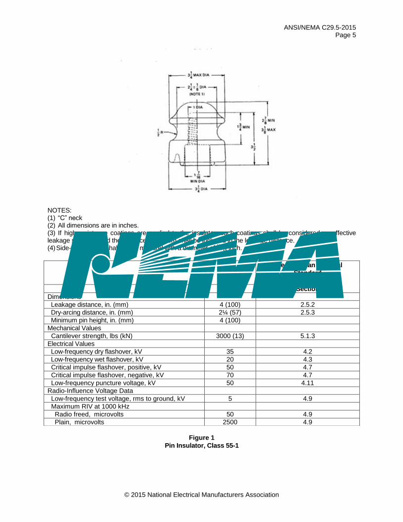
6.1 Figures 1-7 are drawings of insulator types. Dimensions and characteristics of the insulators shall be in accordance with these figures.
ANSI/NEMA C29.5-2015 Page 2
© 2015 National Electrical Manufacturers Association
6.2 When specified, neck designations shall be as shown in Table 1. All surfaces that might come in contact with conductors or tie wires must be rounded to prevent abrasion, cracking, or metal fatigue. The minimum depth of the top conductor groove shall be 0.5 inches for Class 55-2 and Class 55-3 insulators. It shall be 0.6 inches for Class 55-4 and Class 55-5 insulators. It shall be 0.7 inches for Class 55-6 and Class 55-7 insulators. The length of the top conductor groove shall not exceed the maximum neck diameter by more than 0.12 inches.
6.3 All dimensions and other numerical values are given in customary English units. Metric equivalents are given in parentheses for certain characteristics.
Table 1
Neck Designations and Dimensions
7 Marking
Each insulator shall include markings to identify: manufacturer, the ANSI class number or catalog number, and a time/lot reference (as a minimum, the month and year that the item was produced). The marking shall be legible and durable.
8 Sampling, Inspection, and Tests
8.1 GENERAL
Tests described in 8.2 shall be required only on Insulators of new designs. Tests described in 8.3 shall be required on each lot of insulators. Tests described in 8.4 shall be made on each insulator.
8.2 DESIGN TESTS
8.2.1 Low-Frequency Dry Flashover Test
Three insulators shall be selected at random and tested in accordance with Section 4.2 of ANSI C29.1, “Low-Frequency Dry Flashover Test.” Failure of the average dry flashover value of the three insulators to equal or exceed 95% of the rated dry flashover value, as given in the applicable figure, shall constitute failure to meet the requirements of this standard.
8.2.2 Low-Frequency Wet Flashover Test
Three insulators shall be selected at random and tested in accordance with Section 4.3 of ANSI C29.1, “Low-Frequency Wet Flashover Test.” Failure of the average wet flashover value of the three insulators to equal or exceed 90% of the rated wet flashover value, as given in the applicable figure, shall constitute failure to meet the requirements of this standard.
Designation Diameter
Groove-Height
Relationship,
as Applicable (in.) Diameter
Groove-Height
Relationship,
as Applicable (mm)
Letter (in.) Minimum Maximum (mm) Minimum Maximum
A 1¾ ± ⅛ - - 45 ± 3 - -
C 2¼ ± ⅛ 9/16 ⅞ 57 ± 3 14 22
F 2⅞ ± ⅛ 9/16 ⅞ 73 ± 3 14 22
J 3½ ± ⅛ ¼ ⅝ 89 ± 3 6 16
K 4 ± ⅛ ¼ ⅝ 102 ± 3 6 16
N 6 ± ⅛ 9/16 ⅞ 152 ± 3 14 22
ANSI/NEMA C29.5-2015 Page 3
© 2015 National Electrical Manufacturers Association
8.2.3 Critical Impulse Flashover Tests—Positive and Negative
Three insulators shall be selected at random for the critical impulse flashover test, positive, and three for the critical impulse flashover test, negative, and tested in accordance with Section 4.7 of ANSI C29.1, “Impulse Flashover Voltage Tests.” Failure of the average critical impulse flashover value of the three insulators to equal or exceed 92% of the rated critical impulse flashover value, as given in the applicable figure, shall constitute failure to meet the requirements of this standard.
8.2.4 Radio-Influence Voltage Test
Five insulators shall be selected at random and tested in accordance with Section 4.9 of ANSI C29.1, “Radio-Influence Voltage Tests.” If one or more insulators fails to meet the requirements given in the applicable figure, five additional insulators shall be selected at random and tested. Failure of one or more of these additional insulators shall constitute failure to meet the requirements of this standard.
8.2.5 Cantilever-Strength Test
Five insulators shall be randomly selected and tested in accordance with 5.1.3 of ANSI C29.1, “Line Insulators (Pin, Post) (Cantilever Strength).” Failure of the strength of any of the five insulators to meet the strength requirement given in the applicable figure shall constitute failure to meet the requirements of this standard. The re-test procedure in Section 4.3 is applicable to this test.
8.2.6 Thermal Shock Test
Five insulators shall be selected at random and tested for ten complete cycles in accordance with 5.5 of ANSI C29.1, “Thermal Test.” The temperature of the hot water bath shall be approximately 150°F (66°C), and the temperature of the cold water bath shall be approximately 39°F (4°C). If one or more insulators fails, five additional insulators shall be selected at random and tested. Failure of one or more of these additional insulators shall constitute failure to meet the requirements of this standard.
8.3 QUALITY CONFORMANCE TESTS
8.3.1 Dimensional Test
Three insulators shall be selected at random from the lot and their dimensions checked against the dimensions on the manufacturer’s drawing. Failure of more than one of these insulators to conform, within manufacturing tolerances, to the dimensions on this drawing shall constitute failure of the lot to meet the requirements of this standard.
8.3.2 Visual Test
If visual inspection is required on lots of 500 or more insulators, 50 insulators shall be selected at random from the lot. If more than four but fewer than 10 of the insulators fail to meet the requirements of 5.2, 100 additional insulators shall be selected at random from the same lot. Failure of more than a total of 10 insulators from both the first and second samples shall constitute failure of the lot to meet the requirements of this standard.
8.3.3 Porosity Test
A minimum of three specimen samples shall be selected from insulators destroyed in other tests and tested in accordance with 5.4 of ANSI C29.1, “Porosity Test.” Penetration of the dye into the body of the dielectric shall constitute failure of the lot to meet the requirements of this standard.
8.3.4 Pinhole-Gauging Test
Fifteen insulators shall be selected at random and gauged with a gauge similar to that shown in Figure 8 (see page 15). The insulators shall be tested in accordance with 5.6.2 of ANSI C29.1, “Pinhole-Gauging Test.” The clearance between the top of the gauge and the crown of the pinhole cavity shall be not less than ⅛ inch nor more than ¾ inch. The number of turns required to disengage the insulator from the gauge shall average not less than three for the entire sample nor be less than 2¼ for any one insulator. If more than one insulator fails to meet this requirement, 30 additional insulators shall be selected at random and gauged. Failure of more than a total of three insulators from both the first and second samples shall constitute failure of the lot to meet the requirements of this standard.
ANSI/NEMA C29.5-2015 Page 4
© 2015 National Electrical Manufacturers Association
8.3.5 Puncture Test
Three insulators shall be selected at random and tested in accordance with 4.11 of ANSI C29.1, “Puncture Test.” If the average puncture voltage of the three insulators fails to meet the requirement given in the applicable figure, or if the percent average variation exceeds 15%, this shall constitute failure of the lot to meet the requirements of this standard.
8.4 Routine Test (Flashover Test)
Each insulator shall be subjected to a routine flashover test in accordance with 7.1 of ANSI C29.1, “Routine Test.” All insulators that puncture fail to meet the requirements of this standard.
ANSI/NEMA C29.5-2015 Page 5
© 2015 National Electrical Manufacturers Association
NOTES: (1) “C” neck (2) All dimensions are in inches. (3) If high-resistance coatings are applied to the insulator, such coatings shall be considered as effective leakage surfaces, and the distance over them shall be included in the leakage distance. (4) Side-wire groove shall seat a mandrel with a diameter of 15
/16 inch.
Figure 1
Pin Insulator, Class 55-1
See American National
Standard
C29.1
Rating Section
Dimensions
Leakage distance, in. (mm) 4 (100) 2.5.2
Dry-arcing distance, in. (mm) 2¼ (57) 2.5.3
Minimum pin height, in. (mm) 4 (100)
Mechanical Values
Cantilever strength, lbs (kN) 3000 (13) 5.1.3
Electrical Values
Low-frequency dry flashover, kV 35 4.2
Low-frequency wet flashover, kV 20 4.3
Critical impulse flashover, positive, kV 50 4.7
Critical impulse flashover, negative, kV 70 4.7
Low-frequency puncture voltage, kV 50 4.11
Radio-Influence Voltage Data
Low-frequency test voltage, rms to ground, kV 5 4.9
Maximum RIV at 1000 kHz
Radio freed, microvolts 50 4.9
Plain, microvolts 2500 4.9
ANSI/NEMA C29.5-2015 Page 6
© 2015 National Electrical Manufacturers Association
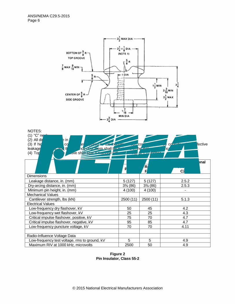
NOTES: (1) “C” neck (2) All dimensions are in inches. (3) If high-resistance coatings are applied to the insulator, such coatings shall be considered as effective leakage surfaces, and the distance over them shall be included in the leakage distance. (4) Top- and side-wire groove shall seat a mandrel with a diameter of 13
/16 inches.
Rating See American National
Standard
C29.1 Plain
Radio
Freed
Dimensions Leakage distance, in. (mm) 5 (127) 5 (127) 2.5.2
Dry-arcing distance, in. (mm) 3⅜ (86) 3⅜ (86) 2.5.3
Minimum pin height, in. (mm) 4 (100) 4 (100) -
Mechanical Values
Cantilever strength, lbs (kN) 2500 (11) 2500 (11) 5.1.3
Electrical Values
Low-frequency dry flashover, kV 50 45 4.2
Low-frequency wet flashover, kV 25 25 4.3
Critical impulse flashover, positive, kV 75 70 4.7
Critical impulse flashover, negative, kV 95 85 4.7
Low-frequency puncture voltage, kV 70 70 4.11
Radio-Influence Voltage Data
Low-frequency test voltage, rms to ground, kV 5 5 4.9
Maximum RIV at 1000 kHz, microvolts 2500 50 4.9
Figure 2
Pin Insulator, Class 55-2

ANSI/NEMA C29.5-2015 Page 7
© 2015 National Electrical Manufacturers Association
NOTES: (1) “C” neck (2) All dimensions are in inches. (3) If high-resistance coatings are applied to the insulator, such coatings shall be considered as effective leakage surfaces, and the distance over them shall be included in the leakage distance. (4) Top- and side-wire groove shall seat a mandrel with a diameter of 11
/16 inches.
Rating See American
National Standard
C29.1 Plain
Radio
Freed
Dimensions Leakage distance, inches (mm) 7 (178) 7 (178) 2.5.2
Dry-arcing distance, inches (mm) 4½ (114) 4½ (114) 2.5.3
Minimum pin height, inches (mm) 5 (127) 5 (127) -
Mechanical Values
Cantilever strength, pounds (kN) 2500 (11) 2500 (11) 5.1.3
Electrical Values
Low-frequency dry flashover, kV 65 55 4.2
Low-frequency wet flashover, kV 35 30 4.3
Critical impulse flashover, positive, kV 100 90 4.7
Critical impulse flashover, negative, kV 130 110 4.7
Low-frequency puncture voltage, kV 90 90 4.11
Radio-Influence Voltage Data
Low-frequency test voltage, rms to ground, kV 10 10 4.9
Maximum RIV at 1000 kHz, microvolts 5500 50 4.9
Figure 3
Pin Insulator, Class 55-3

ANSI/NEMA C29.5-2015 Page 8
© 2015 National Electrical Manufacturers Association
NOTES: (1) “F” neck (2) All dimensions are in inches. (3) If high-resistance coatings are applied to the insulator, such coatings shall be considered as effective leakage surfaces, and the distance over them shall be included in the leakage distance. (4) The side-wire groove shall seat a mandrel with a diameter of 11
/16 inches, but shall not seat a mandrel with a diameter of 1⅜ inches. The top wire groove shall seat a mandrel with a diameter of 1¾ inches.
Rating See American National
Standard
C29.1 Plain
Radio
Freed
Dimensions Leakage distance, in. (mm) 9 (228) 9 (228) 2.5.2
Dry-arcing distance, in. (mm) 5 (127) 5 (127) 2.5.3
Minimum pin height, in. (mm) 5 (127) 5 (127) -
Mechanical Values
Cantilever strength, lbs (kN) 3000 (13) 3000 (13) 5.1.3
Electrical Values
Low-frequency dry flashover, kV 70 65 4.2
Low-frequency wet flashover, kV 40 35 4.3
Critical impulse flashover, positive, kV 110 105 4.7
Critical impulse flashover, negative, kV 140 130 4.7
Low-frequency puncture voltage, kV 95 95 4.11
Radio-Influence Voltage Data
Low-frequency test voltage, rms to ground, kV 10 10 4.9
Maximum RIV at 1000 kHz, microvolts 5500 50 4.9
Figure 4
Pin Insulator, Class 55-4
ANSI/NEMA C29.5-2015 Page 9
© 2015 National Electrical Manufacturers Association
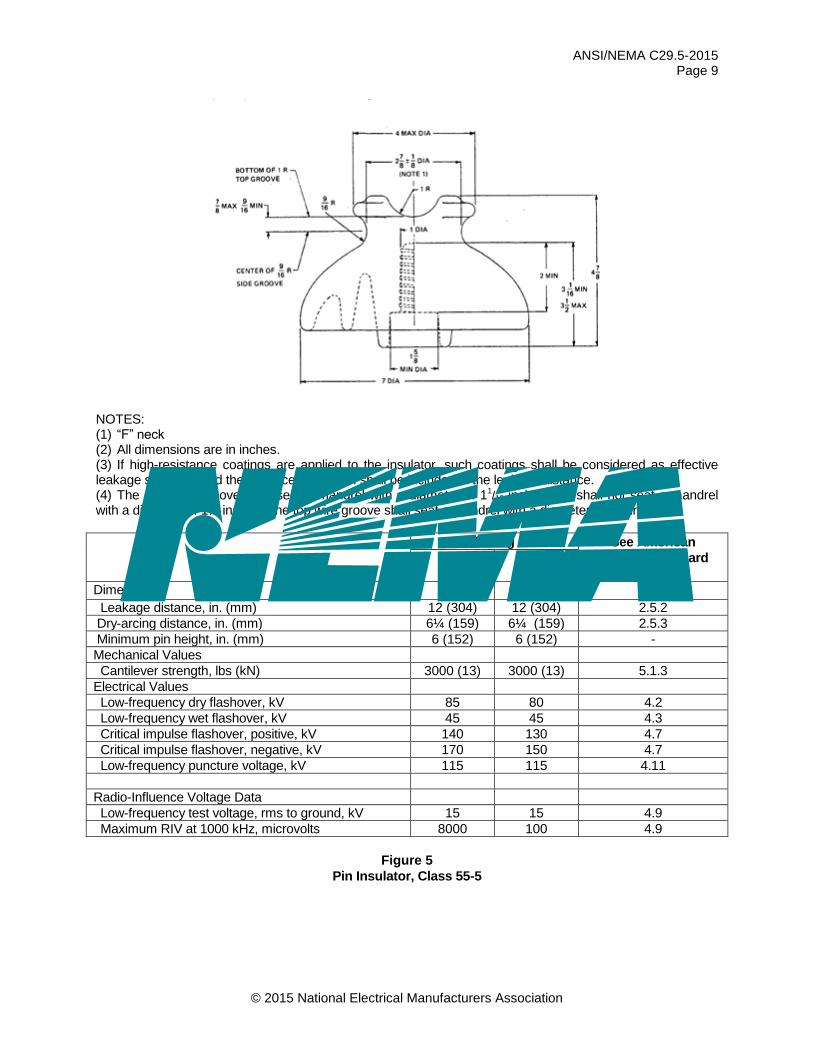
NOTES: (1) “F” neck (2) All dimensions are in inches. (3) If high-resistance coatings are applied to the insulator, such coatings shall be considered as effective leakage surfaces, and the distance over them shall be included in the leakage distance. (4) The side-wire groove shall seat a mandrel with a diameter of 11
/16 inches, but shall not seat a mandrel with a diameter of 1⅜ inches. The top wire groove shall seat a mandrel with a diameter of 1¾ inches.
Rating See American
National Standard
C29.1 Plain
Radio
Freed
Dimensions Leakage distance, in. (mm) 12 (304) 12 (304) 2.5.2
Dry-arcing distance, in. (mm) 6¼ (159) 6¼ (159) 2.5.3
Minimum pin height, in. (mm) 6 (152) 6 (152) -
Mechanical Values
Cantilever strength, lbs (kN) 3000 (13) 3000 (13) 5.1.3
Electrical Values
Low-frequency dry flashover, kV 85 80 4.2
Low-frequency wet flashover, kV 45 45 4.3
Critical impulse flashover, positive, kV 140 130 4.7
Critical impulse flashover, negative, kV 170 150 4.7
Low-frequency puncture voltage, kV 115 115 4.11
Radio-Influence Voltage Data
Low-frequency test voltage, rms to ground, kV 15 15 4.9
Maximum RIV at 1000 kHz, microvolts 8000 100 4.9
Figure 5
Pin Insulator, Class 55-5
ANSI/NEMA C29.5-2015 Page 10
© 2015 National Electrical Manufacturers Association
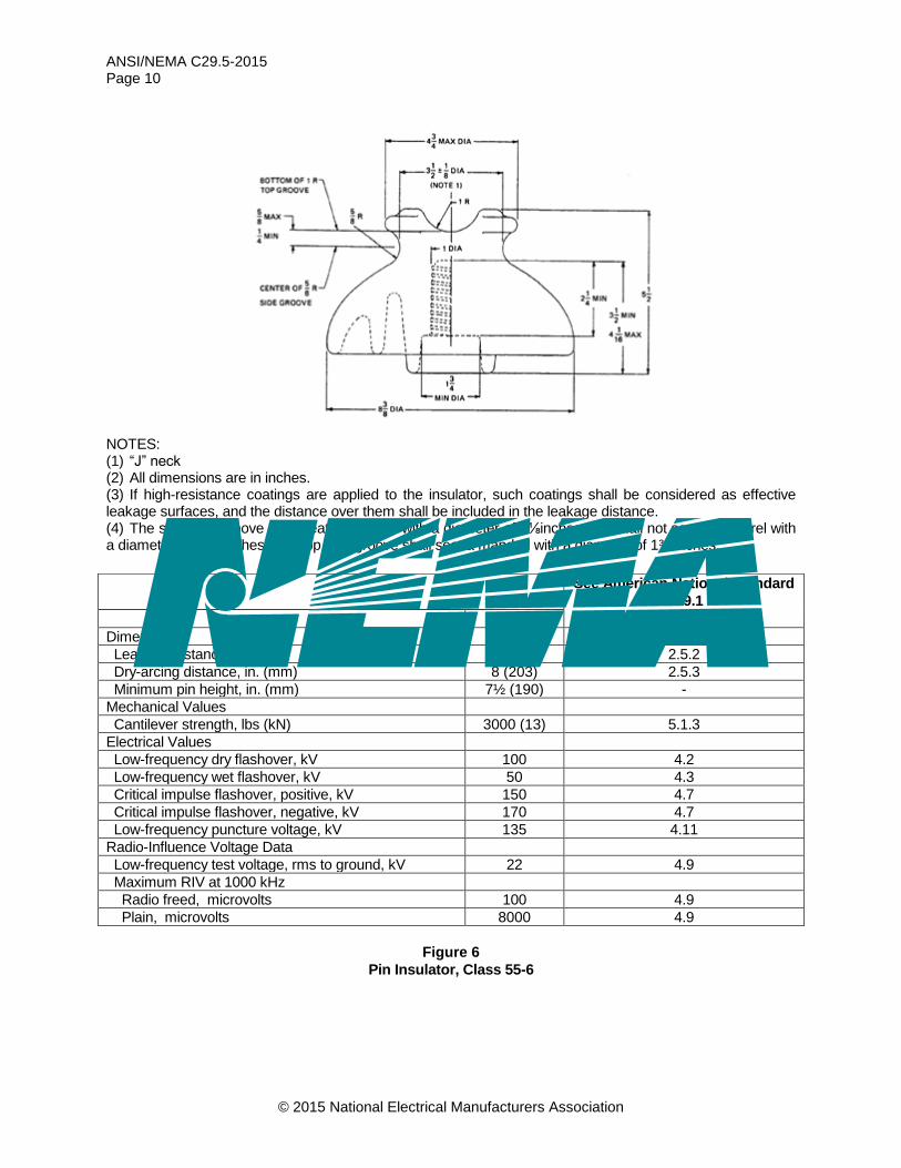
NOTES: (1) “J” neck (2) All dimensions are in inches. (3) If high-resistance coatings are applied to the insulator, such coatings shall be considered as effective leakage surfaces, and the distance over them shall be included in the leakage distance. (4) The side-wire groove shall seat a mandrel with a diameter of 1⅛inches, but shall not seat a mandrel with a diameter of 17
/16 inches. The top wire groove shall seat a mandrel with a diameter of 1¾ inches.
Figure 6
Pin Insulator, Class 55-6
See American National Standard
C29.1
Rating Section
Dimensions
Leakage distance, in. (mm) 15 (381) 2.5.2
Dry-arcing distance, in. (mm) 8 (203) 2.5.3
Minimum pin height, in. (mm) 7½ (190) -
Mechanical Values
Cantilever strength, lbs (kN) 3000 (13) 5.1.3
Electrical Values
Low-frequency dry flashover, kV 100 4.2
Low-frequency wet flashover, kV 50 4.3
Critical impulse flashover, positive, kV 150 4.7
Critical impulse flashover, negative, kV 170 4.7
Low-frequency puncture voltage, kV 135 4.11
Radio-Influence Voltage Data
Low-frequency test voltage, rms to ground, kV 22 4.9
Maximum RIV at 1000 kHz
Radio freed, microvolts 100 4.9
Plain, microvolts 8000 4.9

ANSI/NEMA C29.5-2015 Page 11
© 2015 National Electrical Manufacturers Association
NOTES: (1) “J” neck. (2) All dimensions are in inches. (3) If high-resistance coatings are applied to the insulator, such coatings shall be considered as effective leakage surfaces, and the distance over them shall be included in the leakage distance. (4) The side-wire groove shall seat a mandrel with a diameter of 1⅛inches, but shall not seat a mandrel with a diameter of 17
/16 inches. The top wire groove shall seat a mandrel with a diameter of 1¾ inches. (5) For thread gauge, see Figure 6 of ANSI C29.6.
Figure 7
Pin Insulator, Class 55-7
See American National Standard
C29.1
Rating Section
Dimensions
Leakage distance, in. (mm) 15 (381) 2.5.2
Dry-arcing distance, in. (mm) 8 (203) 2.5.3
Minimum pin height, in. (mm) 7½ (190) -
Mechanical Values
Cantilever strength, lbs (kN) 3000 (13) 5.1.3
Electrical Values
Low-frequency dry flashover, kV 100 4.2
Low-frequency wet flashover, kV 50 4.3
Critical impulse flashover, positive, kV 150 4.7
Critical impulse flashover, negative, kV 170 4.7
Low-frequency puncture voltage, kV 135 4.11
Radio-Influence Voltage Data
Low-frequency test voltage, rms to ground, kV 22 4.9
Maximum RIV at 1000 kHz
Radio freed, microvolts 100 4.9
Plain, microvolts 8000 4.9

ANSI/NEMA C29.5-2015 Page 12
© 2015 National Electrical Manufacturers Association
NOTES: (1) All dimensions are in inches. (2) Unless otherwise specified, a tolerance of ± 0.002 in. (0.05 mm) is allowed on all fractional dimensions. (3) Round all sharp corners to not more than 0.005-inch radius (0.12 mm).
Figure 8
Insulator Thread Gauge

ANSI/NEMA C29.5-2015 Page 13
© 2015 National Electrical Manufacturers Association
APPENDIX (This Appendix is not part of American National Standard C29.5-2015, but is included for information only.)
General Information Packaging of insulators should be such as to afford reasonable and proper protection to the insulators in shipping and handling. Each box or container should be marked with the number of insulators contained therein, the catalog number, class number, or a description of the contents, and the manufacturer’s name. Manufacturers should maintain records of the plant in which the insulator was produced. §

![India Year Book 2015 part 1 for WBCS MAIN[Watermarked]](https://static.fdocuments.net/doc/165x107/577cb55a1a28aba7118d127b/india-year-book-2015-part-1-for-wbcs-mainwatermarked.jpg)