ANSI TIA EIA 570 - godinweb Stan… · PPT file · Web view · 2017-12-18ANSI/TIA 570B....
33
ANSI/TIA 570B Residential Telecommunications Infrastructure Standard 1 Updated Dec 2016 PRGodin ©PRGodin @gmail.com
Transcript of ANSI TIA EIA 570 - godinweb Stan… · PPT file · Web view · 2017-12-18ANSI/TIA 570B....

ANSI/TIA 570BResidential Telecommunications Infrastructure Standard
1Updated Dec 2016 PRGodin©PRGodin @gmail.com

IntroductionOriginally a standard for small
commercial buildings the 570B standard has migrated to primarily address residential installations.
Communication infrastructures are still relatively new in the residential construction market but have become common for new construction.
2

General RequirementsCommunication cabling infrastructures in
single-dwelling residences need to support a wide variety of communication requirements. The cabling structure needs to address:VoiceDataVideoSecurityWhole-home audioControl system
3

Single Dwelling Residence Infrastructure
Sour
ce: A
NSI-T
IA-E
IA-5
70 S
tand
ard
4
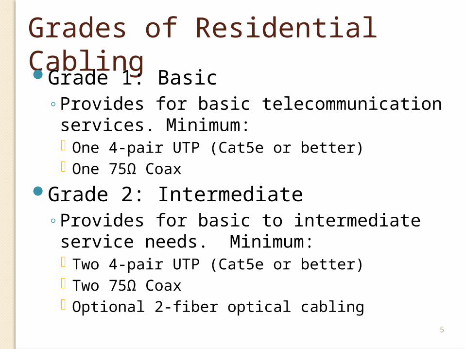
Grades of Residential CablingGrade 1: Basic
Provides for basic telecommunication services. Minimum: One 4-pair UTP (Cat5e or better) One 75Ω Coax
Grade 2: IntermediateProvides for basic to intermediate service
needs. Minimum: Two 4-pair UTP (Cat5e or better) Two 75Ω Coax Optional 2-fiber optical cabling
5
Some DefinitionsDemarcation point: Point where
ownership of the hardware changesDistribution Device (DD): Central
facility used to connect outlets within the residence and to the service providers
ADO Cable: Connectorized cable assembly used to connect between the demarcation point and the DD.
6

Typical 570B Residential Installation
7Source: ANSI-TIA-EIA-570 Standard

The Distribution Device (DD)The DD may consist of:
Passive cross-connectionsActive cross-connectionsA combination of passive & active cross-connections
The DD is installed within the tenant’s space in a centralized location that is easy to access
The DD should be capable of handling all communication requirements
8

Space for the DDThere is a guideline for space to allocate for
the DD
The DD can be installed either on a backboard or between wall studs.
Multiple interconnected DDs may be used within the same space
DDs usually require electrical service9

DD Space Allocation Chart
10Source: ANSI-TIA-EIA-570 Standard

Outlet CablesCables are run from the DD to the
telecom outlets in a star topology.Cables shall not exceed 90 meters,
with an additional 10 meters for patch cords and jumpers.
Recognized cables:4pr UTP (cat 5e or better)Coax RG-6 (RG59 for CCTV only) foil &
braidOptical fiber (50, & 62.5 MM, SM)
11

Room RequirementsMinimum of one outlet location for each of
these rooms:KitchenBedroomFamily RoomDen/Study Room
Additional outlets should be installed where:there is more than 3.7 meters (12ft) along a
continuous wallThere is more than 7.6 meters (25ft) along a
broken wall12

Examples of Room Outlet Location
13Source: ANSI-TIA-EIA-570 Standard
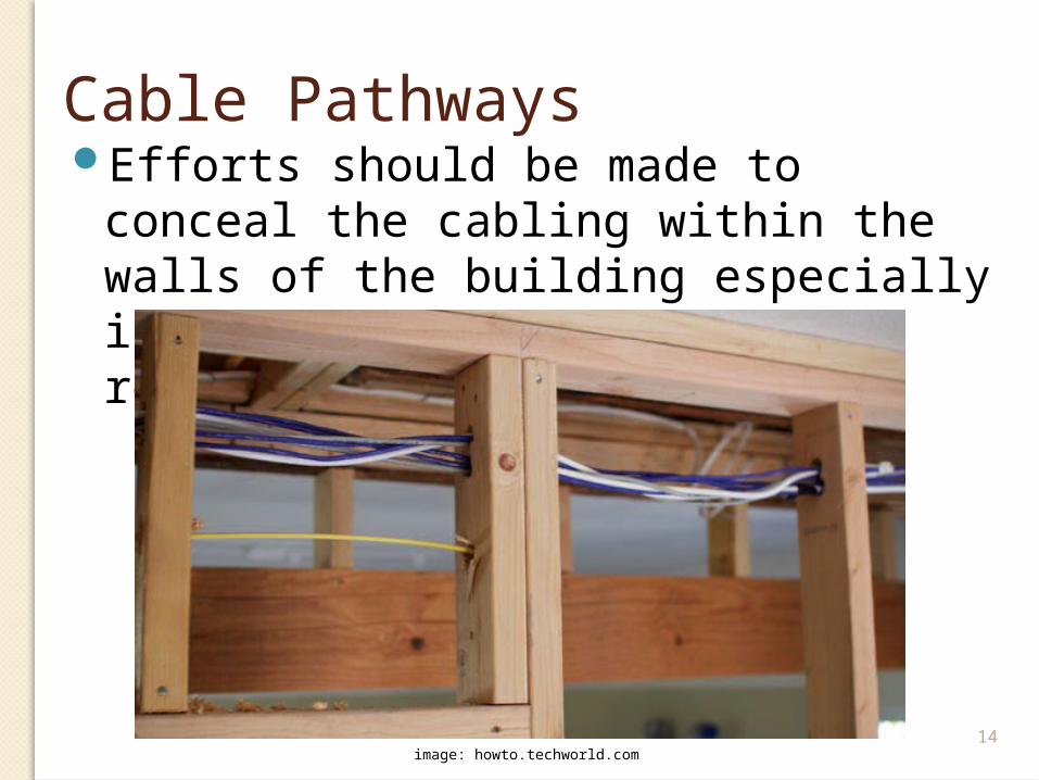
Cable PathwaysEfforts should be made to conceal the
cabling within the walls of the building especially in new construction and remodeling.
14image: howto.techworld.com

Special Case CablingAlarm, Control and other cables may fall under
the jurisdiction of local and national codes and laws.
The standard provides installation suggestions but is not meant to overrule specific legal and performance requirements.
15

Special Case: Alarm/Security CableSecurity alarm systems may consist of:
Sensors Motion, breakage or shock detectors Door and window contacts Sound & Pressure sensors Water & temperature sensors Smoke, heat and CO2 sensors
Control panels Entry keypads and manual activators 1 and/or 2-way audio and/or video Alerting devices (siren, strobes, bells, etc) Remote (personal) devices Door and window latch operators Lighting control Remote connection
16

Alarm/Security Systems CableShould be run in a physical star topology. Daisy-
chaining some devices may be the standard connection method but it is not recommended.
Fire systems are subject to regulation by the US NEC.
Typical security systems cable: 16 or 18 AWG stranded or 22 AWG solid conductors 4 conductor (active devices) or 2 conductor (passive
devices)
17

Video Cabling
RG 59 for baseband video (such as CCTV)
RG 6 for broadband (CATV, Satellite)
Cat 5e/6 may be used with a balun
18

Home AudioLocation of the audio systems is important
for performance quality and ease of control. Follow manufacturer recommendations for installation locations and requirements
Three areas of control:Headend (DD) to distribution deviceDistribution device to volume controlVolume control to the speaker
19

20
Sour
ce: A
NSI-T
IA-E
IA-5
70 S
tand
ard

Audio CableHeadend (DD) to distribution:
one cat 5e/6 4 conductor speakers for left and right 2 conductors for control
Distribution to Volume control & Volume control to speakers one cat 5e/6 4 conductors for 1 or 2 speakers
21

Audio Cable AWG The AWG is based on the wattage of the speakers and the
length of the cable. Conductors should be red(+) and black(-), and for 4-conductors should include white(+) and green(-).
22Source: ANSI-TIA-EIA-570 Standard

Control SystemsClimate control, lighting control and
other home automation:Recommend following manufacturer’s
recommendations for cablingThe standard recommends running a can
5e/6 between the active elements of the system to “accommodate a large variety of climate control options”.
23

Multi-Dwelling & Campus InfrastructuresMulti-dwelling buildings may have a single
services demarcation and redistribute the service to the individual dwellings.
24
Serv
ices
Prov
ider
(s)
ADO/DD
Unit 1
ADO/DD
Unit 2
ADO/DD
Unit 3
Unit 4 Unit 5
ADO/DD
Unit 6
Unit 7
ADO/DD
Unit 8
ADO/DD ADO/DD
Common Equipment
Room
ADO/DDEntrance
Facility

DistancesThe Entrance Facility should be connected to a
separate common Equipment Room. This room should permit shared access for services and for the building management’s services.
If the distance from the ER to the furthest dwelling is more than 150 meters the service provider should be advised.
Limitations between the DD an outlets in the dwelling are limited to a maximum of 90 meters.
25

Larger Multi-Dwelling & Campus InfrastructuresIf there are a large number of floors or units a CTR,
or Common Telecommunications Room, should be located on each floor or on each 3rd floor.
26
Serv
ices
Prov
ider
(s)
ADO/DD
Unit 1
ADO/DD
Unit 2
ADO/DD
Unit 3
Unit 4 Unit 5
ADO/DD
Unit 6
Unit 7
ADO/DD
Unit 8
ADO/DD
Common Equipment
Room
ADO/DDEntrance
Facility
CTR
ADO/DDCTR

Campus Telecommunication RequirementsCampus environments may consist of
separate buildings.Interconnecting backbones should be
contained within conduit, aerially or within interconnecting tunnels.
Building entrance protection must be implemented where required
27

Backbone CablingMulti-conductor copperMulti-pair 100Ω UTPSeries 6 & 11 coax (RG6 triple and
quad shield and RG11)Series 59 coax (CCTV only)Other coaxial (“hardline”)Fiber Optics (50 & 62.5MM, SM)
28

Telecommunications OutletTelephone outlet with mounting studs
permitted8 position mod jacks that meet the
568 standards (may be used with 6 pos plugs)
Coax F connectors
Recommendation is that patch cords be factory made.
29

Other IssuesAll firestop requirements must be
followedSecondary protection must be
installedGrounding must be implemented
30

Electromagnetic NoiseData communications cable must be run with at
least 2 inches of separation from a parallel power cable within a wall and 6 inches of separation from cables going to active security devices.
Security cable must maintain at least 6 inches of separation from power cables.
Audio cable should have at least 12 inches of separation from data communication cable
31
Typically 12” of separation is recommended in all cases.

Testing and AdministrationTesting should follow the 568C
standards
Administration should follow the 606B standards.
Pathways planning should follow the 569B standard.
32

ConclusionThe 570B standard addresses small
installations and installations for residential units. These installations typically make use of a greater variety of communication requirements.
The standard relies on other standards for administration, testing, cable performance and documentation. 33
ENDprgodin @ gmail.com