ANSI TECHNOLOGIES SDN BHD
27
ANSI TECHNOLOGIES SDN BHD Madur/SENSONIC FLUE GAS ANALYSER WITH SAMPLE CONDITION SYSTEM pg. 1 Issued 1.0 Date: December 11
Transcript of ANSI TECHNOLOGIES SDN BHD
ANSI TECHNOLOGIES SDN BHDMadur/SENSONIC FLUE GAS ANALYSER
WITHSAMPLE CONDITION SYSTEM
pg. 1 Issued 1.0 Date: December 11

ANSI TECHNOLOGIES SDN BHDMadur/SENSONIC FLUE GAS ANALYSER
WITHSAMPLE CONDITION SYSTEM
pg. 2 Issued 1.0 Date: December 11
ANSI TECHNOLOGIES SDN BHDMadur/SENSONIC FLUE GAS ANALYSER
WITHSAMPLE CONDITION SYSTEM
pg. 3 Issued 1.0 Date: December 11
Index
Chapter Description Page1.0 Notice 4
2.0 Document History 4
3.0 Safety Information 5
4.0 Overview 6
5.0 Parts/Equipment List 7 - 16
6.0 P & ID Schematic 17 - 22
7.0 Wiring Termination 23
8.0 System Start Up & Shut Down 24
9.0 Maintenance 25
10.0 Consumable Spare Parts List 26

ANSI TECHNOLOGIES SDN BHDMadur/SENSONIC FLUE GAS ANALYSER
WITHSAMPLE CONDITION SYSTEM
pg. 4 Issued 1.0 Date: December 11
1.0) NoticePlease be advice to read this user manual carefully before performing installation, wiring, operation, and maintenanceof the system. Improper handling may result in accidents or injury.
The specification of the design sampling system are subject to change without prior notice for further productimprovement
Modification of to the supplied system is strictly prohibited unless a written approval is obtained from Manufacturer. JKENVIROTECH SDN BHD will not bear any responsibility for any direct or indirect damage or faulty caused by such amodification.
Strictly advice only qualified trained personal allow to perform any service or maintenance work
This document and design is a properties of JK ENVIROTECH SDN BHD; strictly no photocopied, reproduced, ortranslated to another language without the prior written consent form JK ENVIROTECH SDN BHD
2.0) Document HistoryIssued By Date Version Reason for UpdateHenry Por December 30, 2019 1.00

ANSI TECHNOLOGIES SDN BHDMadur/SENSONIC FLUE GAS ANALYSER
WITHSAMPLE CONDITION SYSTEM
pg. 5 Issued 1.0 Date: December 11
3.0) Safety InformationGeneral Hazard
Handle the system with care; improper handling may result immediate danger to life or healtheffect; or lead to unintended equipment or properties damage
Electrical Hazard
System operated with 230VDC and 24VDC, ensure all wiring connection connected in correctposition and securely tighten and do not modify the wiring without prior notice tomanufacturer; risk of electric shock and equipment damage
Pressure Hazard
System require 4 Bar instrument air pressure for back purge; do not increase or change anypre-set pressure output into the system without getting concern from manufacturer, changemay results damage to the system equipment;
Should you require any maintenance to the instrument air service to the system, ensure toisolate or shut off the incoming instrument air supply before perform any maintenance work
Hot Surface Hazard
The sample probe filter and surface may be heated up due to incinerator combustion processburning, where the hot surface sufficient to cause minor burn body injury
Do not touch the surface without safety glove; allow the system to cool down for at least 30minutes before carry out any maintenance work;

ANSI TECHNOLOGIES SDN BHDMadur/SENSONIC FLUE GAS ANALYSER
WITHSAMPLE CONDITION SYSTEM
pg. 6 Issued 1.0 Date: December 11
4.0) OverviewThe Madur/Sensonic Flue Gas Analyser System specially design in accordance to client requirement fordomestic waste incinerator combustion monitoring;
The combustion gas analyser system design to measure incinerator process combustion measuring gasesinclude carbon monoxide, oxygen and carbon dioxide (calculation)
System built up combine with new parts & refurbish existing system(Refer to figure 1 & 2 for more detail)
ANSI TECHNOLOGIES SDN BHDMadur/SENSONIC FLUE GAS ANALYSER
WITHSAMPLE CONDITION SYSTEM
pg. 7 Issued 1.0 Date: December 11
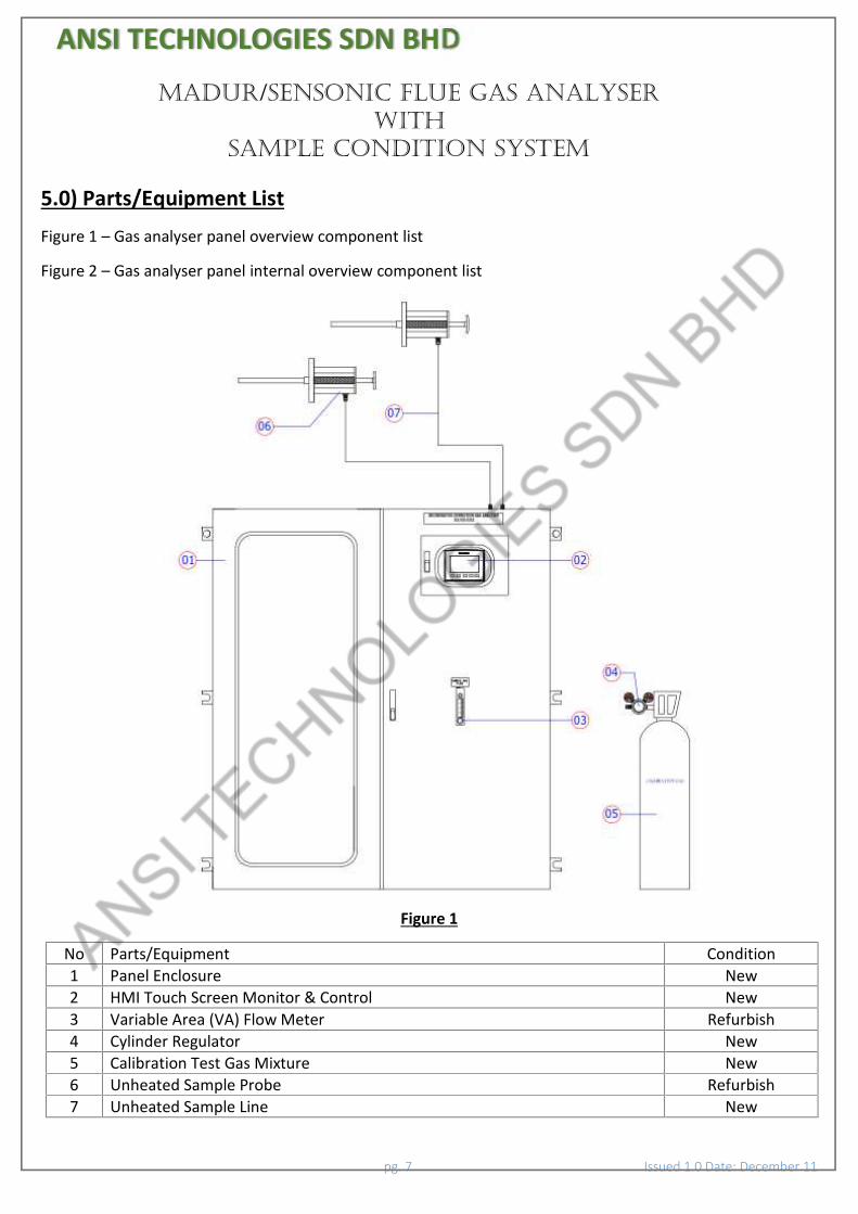
5.0) Parts/Equipment ListFigure 1 – Gas analyser panel overview component list
Figure 2 – Gas analyser panel internal overview component list
Figure 1
No Parts/Equipment Condition1 Panel Enclosure New2 HMI Touch Screen Monitor & Control New3 Variable Area (VA) Flow Meter Refurbish4 Cylinder Regulator New5 Calibration Test Gas Mixture New6 Unheated Sample Probe Refurbish7 Unheated Sample Line New

ANSI TECHNOLOGIES SDN BHDMadur/SENSONIC FLUE GAS ANALYSER
WITHSAMPLE CONDITION SYSTEM
pg. 8 Issued 1.0 Date: December 11
Figure 2
No Parts/Equipment Condition8 Gas Analyser New9 Ventilation Fan New
10 Pressure Switch New11 Gas Cooler/Dryer Refurbish12 Automatic Condensate Drain Refurbish13 2 Way Solenoid Valve A New14 2 Way Solenoid Valve B New15 2 Way Solenoid Valve C New16 3 Way Solenoid Valve B New17 Ventilation Fan New18 Sample Pump Refurbish19 Back Purge Filter/Regulator New20 3 Way Solenoid Valve A New21 Water Trap/Float Switch New22 System Power/Control/Signal Distribution New23 Fluorescent Light New

ANSI TECHNOLOGIES SDN BHDMadur/SENSONIC FLUE GAS ANALYSER
WITHSAMPLE CONDITION SYSTEM
pg. 9 Issued 1.0 Date: December 11
Gas AnalyserThe gas analyser measuring 2 gas parameter and 1 calculation;
No Parameter Sensor Type Range1 Oxygen Partial Pressure 0 – 25%vol2 Carbon Monoxide Infrared (NDIR) 0 – 10,000 ppm3 Carbon Dioxide Calculation 0 – 100%vol
Gas Analyser Sensor DriftOver the time of measurement, sensor will experience drift; to maintain the sensor measured accurately, thegas analyser will perform auto zero air calibration on daily basis
Solubility of GasesSolubility of gases is a major concern, thus understanding of solubility of gases is important to determine typeof sampling system;
Gas like ammonia & sulphur dioxide cannot measure accurately if present of excess water;
Gases like carbon monoxide and oxygen does not affected much
At 20 degree Celsius, solubility of target measurement gas is minimal, thus non heated solution is acceptablefor measurement
Carbon Monoxide Oxygen Carbon Dioxide
Frequency of serviceTo ensure the gas analyser perform in optimum performance, we recommended the gas analyser to carry outservice, calibration and consumable parts replacement on 6 monthly basis;(Note: Only qualified train personal or specialist allow to carry out any service and maintenance work)
ANSI TECHNOLOGIES SDN BHDMadur/SENSONIC FLUE GAS ANALYSER
WITHSAMPLE CONDITION SYSTEM
pg. 10 Issued 1.0 Date: December 11
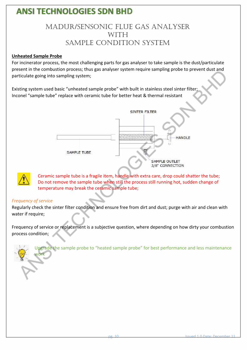
Unheated Sample ProbeFor incinerator process, the most challenging parts for gas analyser to take sample is the dust/particulatepresent in the combustion process; thus gas analyser system require sampling probe to prevent dust andparticulate going into sampling system;
Existing system used basic “unheated sample probe” with built in stainless steel sinter filter;Inconel “sample tube” replace with ceramic tube for better heat & thermal resistant
Ceramic sample tube is a fragile item, handle with extra care, drop could shatter the tube;Do not remove the sample tube when still the process still running hot, sudden change oftemperature may break the ceramic sample tube;
Frequency of serviceRegularly check the sinter filter condition and ensure free from dirt and dust; purge with air and clean withwater if require;
Frequency of service or replacement is a subjective question, where depending on how dirty your combustionprocess condition;
Upgrade the sample probe to “heated sample probe” for best performance and less maintenancework

ANSI TECHNOLOGIES SDN BHDMadur/SENSONIC FLUE GAS ANALYSER
WITHSAMPLE CONDITION SYSTEM
pg. 11 Issued 1.0 Date: December 11
Unheated Sample LinePTFE material is the best corrosive resistant against many corrosive gas; thus commonly used in gas analysersampling;
The system used basic PTFE sample line/tube to transfer the sample gas probe to gas analyser;
Frequency of serviceRegularly check the sample line tube and ensure no dirt blockage, bend and water droplet blockage;
The system equipped with back purge system; system will back purge to clear the sample line automaticallyevery 1 hours for 10 second;
Heated sample line is the better solution and less maintenance work to transfer the sample gas;as water droplet do not form when heated up;Alternatively, sample probe complete with cooler/dryer or nafion dryer for dry sample solutioncan be integrated into the system
Gas Cooler/DryerInfrared sensor (carbon monoxide) cannot measure accurately if present of water vapour in the system; watervapour absorb infrared wavelength
The combustion gas analyser system integrated with gas cooler/dryer in the system;
At low temperature, vapour will turn into liquid droplet due to condensation, the cooler/dryer cooling downat approximately 5 degree Celsius, thus will turning the sampling gas vapour into dry gas before channel outthe sample to gas analyser for analysis
Gas cooler/dryer integrated with the HMI & sample pump system; the sample pump cannotactivated if the gas cooler/dryer temperature above 12 degree Celsius;System warm up take approximately 15 minutes to reach the target condition at 5 degree Celsius
Frequency of serviceRegularly check the gas cooler/dryer sample tube and ensure no excessive dirt or dust trap within the tube;

ANSI TECHNOLOGIES SDN BHDMadur/SENSONIC FLUE GAS ANALYSER
WITHSAMPLE CONDITION SYSTEM
pg. 12 Issued 1.0 Date: December 11
Water Trap/ Float SwitchDue to unheated sample line, excess water droplet may present along the sample line;
As the pump draw in the sample, the volume of excess water may be too much for the cooler dryer/automaticcondensate drain to handle.
Thus, system integrated with a water trap/float switch unit to trap the excess water and the solenoid valvewould automatically drain out the excess water once the float switch detect maximum water level inside thecylinder housing;
Water Trap/Float Switch design to trap excess water into the sample line; not efficient tocondensate gas vapour into water droplet;Gas cooler/dryer design to condensate gas vapour into water droplet
Frequency of serviceRegularly check the filter and ensure no excessive dirt or dust trap within the filter;
Automatic Condensate DrainPTFE automatic condensate drain integrated with gas cooler dryer to trap and drain automatically thecollected water droplet from the gas cooler dryer sampling;
Automatic condensate drain require positive pressure sampling system to work well;Do not use for vacuum/negative pressure sampling system, this will result inaccuratemeasurement reading due to possible outside air may slip in from drain port

ANSI TECHNOLOGIES SDN BHDMadur/SENSONIC FLUE GAS ANALYSER
WITHSAMPLE CONDITION SYSTEM
pg. 13 Issued 1.0 Date: December 11
Sample PumpThe sample pump is primary pump, use to transfer the sample gas from the sample probe to gas analyser;build with corrosive resistant wet parts to withstand corrosive gas sample;
The pump have capacity of 400 litre/hour or about 6.7 l/min free flow; thus efficiently transfer the sample gasto gas analyser in less than 12 second given pipe length at 100 meter and pipe size at 3/8” absolute condition;
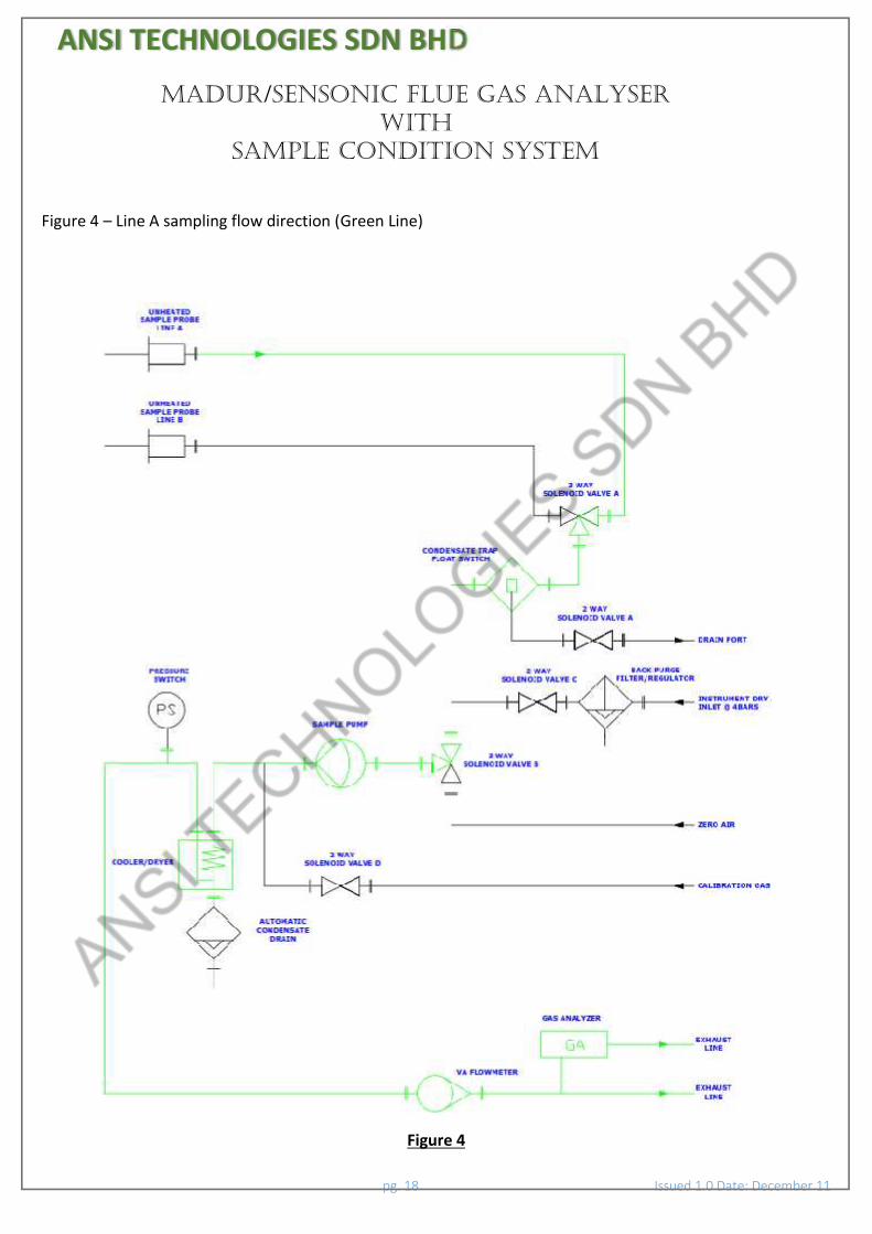
The sample pump do not flow in directly into gas analyser to prevent damage to the gas analyser sensor orinaccurate reading due to the pressure built up;(Note: Refer figure 4.0/5.0 for better understanding)
The sample pump will flow through a T-fitting allowing the gas analyser built in secondary pump to draw inthe sample at 1 to 1.5 l/min
Frequency of serviceCheck the sample pump wetted parts on 6 monthly basis and ensure no excessive dirt or dust trap within thetube
2 & 3 Way Solenoid ValveDue to corrosive gas present in the sample line, system equipped with DC24V stainless steel valve to channelthe sample gas or back purge path way; all the valve function is integrated and control by HMI system
No Solenoid Valve Function1 2 Way Solenoid Valve A Condensate trap/float switch drain valve2 2 Way Solenoid Valve B Calibration gas valve3 2 Way Solenoid Valve C Back purge system valve4 3 Way Solenoid Valve A Selection between sampling & zero air valve5 3 Way Solenoid Valve B Selection between line A & B

ANSI TECHNOLOGIES SDN BHDMadur/SENSONIC FLUE GAS ANALYSER
WITHSAMPLE CONDITION SYSTEM
pg. 14 Issued 1.0 Date: December 11
Back Purge Filter/Regulator;Heavy dust and particulate is an issue for waste incinerator combustion process, thus the system equippedwith back purge system to minimize the frequency of filter replacement
The system require 4 bar instrument/compress air
VA Flowmeter & Pressure SwitchSystem equipped with variable area (VA) flowmeter and pressure switch as the indication to check should thesample inlet blockage detected;
ANSI TECHNOLOGIES SDN BHDMadur/SENSONIC FLUE GAS ANALYSER
WITHSAMPLE CONDITION SYSTEM
pg. 15 Issued 1.0 Date: December 11
Calibration Gas MixtureThe system supplied include calibration test gas mixture for span check the gas analyser accuracy
The cylinder gas mixture typically have 2 years life shelf; require refill or replacement once expired;
The expiry date can be found at the cylinder gas mixture certificate
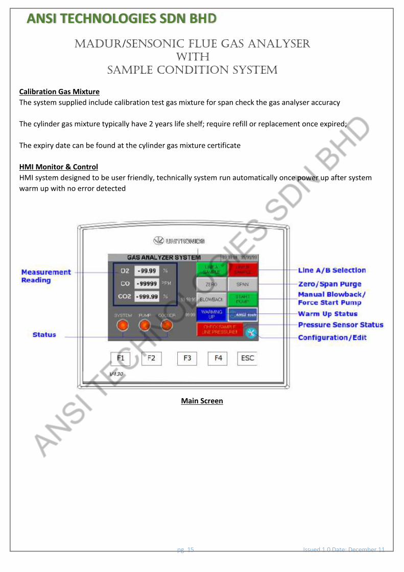
HMI Monitor & ControlHMI system designed to be user friendly, technically system run automatically once power up after systemwarm up with no error detected
Main Screen

ANSI TECHNOLOGIES SDN BHDMadur/SENSONIC FLUE GAS ANALYSER
WITHSAMPLE CONDITION SYSTEM
pg. 16 Issued 1.0 Date: December 11
Configuration/Edit Screen

ANSI TECHNOLOGIES SDN BHDMadur/SENSONIC FLUE GAS ANALYSER
WITHSAMPLE CONDITION SYSTEM
pg. 17 Issued 1.0 Date: December 11
6.0 P & ID SCHEMATICFigure 3 – Madur/Sensonic flue gas analyser with sample condition system piping & instrumentation diagram
Figure 3
ANSI TECHNOLOGIES SDN BHDMadur/SENSONIC FLUE GAS ANALYSER
WITHSAMPLE CONDITION SYSTEM
pg. 18 Issued 1.0 Date: December 11
Figure 4 – Line A sampling flow direction (Green Line)
Figure 4

ANSI TECHNOLOGIES SDN BHDMadur/SENSONIC FLUE GAS ANALYSER
WITHSAMPLE CONDITION SYSTEM
pg. 19 Issued 1.0 Date: December 11
Figure 5 – Line B sampling flow direction (Green Line)
Figure 5
ANSI TECHNOLOGIES SDN BHDMadur/SENSONIC FLUE GAS ANALYSER
WITHSAMPLE CONDITION SYSTEM
pg. 20 Issued 1.0 Date: December 11
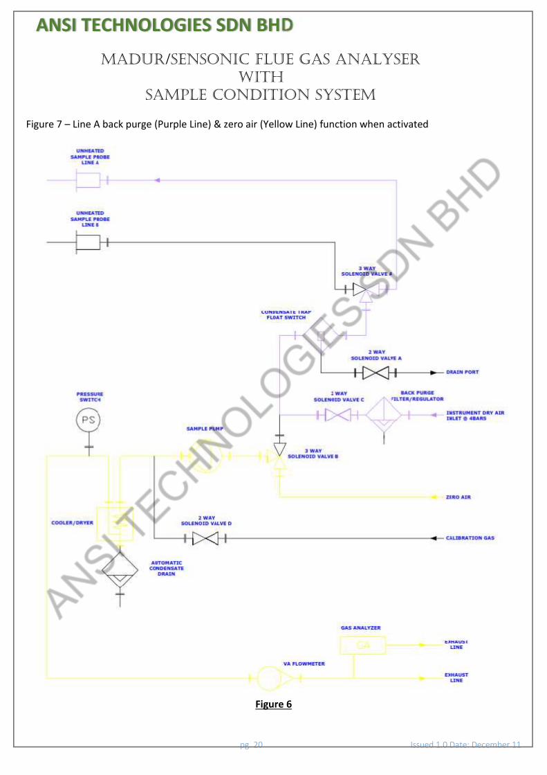
Figure 7 – Line A back purge (Purple Line) & zero air (Yellow Line) function when activated
Figure 6

ANSI TECHNOLOGIES SDN BHDMadur/SENSONIC FLUE GAS ANALYSER
WITHSAMPLE CONDITION SYSTEM
pg. 21 Issued 1.0 Date: December 11
Figure 7 – Line B back purge (Purple Line) & zero air (Yellow Line) function when activated
Figure 7

ANSI TECHNOLOGIES SDN BHDMadur/SENSONIC FLUE GAS ANALYSER
WITHSAMPLE CONDITION SYSTEM
pg. 22 Issued 1.0 Date: December 11
Figure 8 – Calibration test gas function (Yellow Line) flow direction
Figure 8

ANSI TECHNOLOGIES SDN BHDMadur/SENSONIC FLUE GAS ANALYSER
WITHSAMPLE CONDITION SYSTEM
pg. 23 Issued 1.0 Date: December 11
7.0 Wiring TerminationIncoming Power Wiring TerminationIncoming power requirement to the system is 230VAC @ 16A;(Figure 13.0 – Incoming Power Wire Termination Terminal)
Figure 13.0
Analogue 4-20 Signal Output Wiring Termination3 x 4 -20mA signal output; The range setting pre-set according HMI monitor
We advise only well trained electrician or engineer that fully understood to basic of electricalinstrument & control circuitry connection allow to make any intended electrical connection;consult with JK Envirotech Sdn Bhd should you require assistant for electrical signal termination
Direct ConnectionThe following Figure 14.0 shown direct 2 wire active 4-20mA connection;
Figure 14.0

ANSI TECHNOLOGIES SDN BHDMadur/SENSONIC FLUE GAS ANALYSER
WITHSAMPLE CONDITION SYSTEM
pg. 24 Issued 1.0 Date: December 11
8.0 System Start Up & Shut DownSystem Power UpThe system design to be user friendly and straight forward system; follow the following basic step to start upthe system
Step 1 : Turn on the incoming main power supply MCBStep 2 : Allow the system to warm up (15 minutes)Step 3 : Select the Line selection (HMI Screen)Step 4 : Check & ensure the gas cooler dryer below < 12 degree CelsiusStep 5 : After 15 minutes, sample pump will turn on automaticallyStep 7 : Check the HMI screen and ensure no error messageStep 8 : Check the VA flowmeter and ensure the flow rate between 4 – 6 l/minStep 9 : System ready to operate
System Shut Down
Step 1 : On the HMI screen, turn on air zero and purge the system for approximately 10 minutes;this is to ensure no residual gas left inside the sample line that may possible damage thewetted parts after sometime
Step 2 : After 10 minutes, turn off the main incoming power supply

ANSI TECHNOLOGIES SDN BHDMadur/SENSONIC FLUE GAS ANALYSER
WITHSAMPLE CONDITION SYSTEM
pg. 25 Issued 1.0 Date: December 11
9.0 MaintenanceTo maintain the system to optimum performance, we recommend the system to carry out daily, 6 monthlyand yearly basis maintenance work;
Daily maintenance checking work consider pretty straight forward work; can be carry out by well-trainedengineer to operate the system
JK Envirotech (M) Sdn Bhd strongly advise user/operator to engage with our service team for 6 monthly andyearly basis maintenance work; this is due to the service work require technical competent person to performthe work; JK Envirotech Sdn Bhd happy to assist and train the engineer, should user/operator prefer toperform own service work
The following diagram is recommend maintenance schedule time frame:Maintenance Schedule
ComponentSchedule
Daily 6-Monthly YearlyCheck the sample probe condition ✔Check the gas cooler/dryer condition ✔Check the sample line condition ✔Check the HMI screen and ensure no error ✔Check the condensate trap/float switch filter condition ✔Check the VA flowmeter and ensure within pre-set range ✔Span check the analyser with cylinder test gas if necessary ✔HMI screen functional test work ✔Zero & span calibration ✔Sample pump wetted part condition inspection ✔Consumable parts replacement ✔ ✔

ANSI TECHNOLOGIES SDN BHDMadur/SENSONIC FLUE GAS ANALYSER
WITHSAMPLE CONDITION SYSTEM
pg. 26 Issued 1.0 Date: December 11
10.0 Consumable Spare Part List
Sample ProbeNo Spare Part Description Part Number1 Replacement sinter filter BHNH-SF-5M
Gas AnalyserNo Spare Part Description Part Number1 Replacement oxygen sensor O2-252 Liquid blocker filter LBF-0.013 Replacement pump unit DP-00014 Replacement 2 way solenoid valve SV-025 Replacement 3 way solenoid valve SV-03
Sample Diaphragm PumpNo Spare Part Description Part Number1 Sample pump service kits BH-P2.4
Condensate Trap / Float SwitchNo Spare Part Description Part Number1 Replacement sinter filter CT-SF-5M2 Replacement float switch CT-FS
Back Purge Filter/RegulatorNo Spare Part Description Part Number1 Service Kits 4383-600
Calibration gas mixtureNo Spare Part Description Part Number1 Gas Refilling CG-RF
ANSI TECHNOLOGIES SDN BHDMadur/SENSONIC FLUE GAS ANALYSER
WITHSAMPLE CONDITION SYSTEM
pg. 27 Issued 1.0 Date: December 11
![[XLS]nexi.go.jpnexi.go.jp/topics/mt_file/to_20121001_1.xls · Web viewISRO MOTORS SDN. BHD. ZAMAN MOTORS SDN. BHD. JABIL CIRCUIT SDN. BHD. NGYY HEAVY EQUIPMENT TRADING SDN. BHD. NATIONGATE](https://static.fdocuments.net/doc/165x107/5aa778367f8b9a54748c1663/xlsnexigo-viewisro-motors-sdn-bhd-zaman-motors-sdn-bhd-jabil-circuit-sdn.jpg)