
Anritsu VNA
652
SERIES 37XXXC VECTOR NETWORK ANALYZER OPERATION MANUAL 490 JARVIS DRIVE · MORGAN HILL, CA 95037-2809 P/N: 10410-00226 REVISION: E PRINTED: MARCH 2004 COPYRIGHT 2004 ANRITSU CO.
description
Anritsu VNA
Transcript of Anritsu VNA

SERIES37XXXC
VECTOR NETWORK ANALYZER
OPERATION MANUAL
490 JARVIS DRIVE MORGAN HILL, CA 95037-2809 P/N: 10410-00226REVISION: E
PRINTED: MARCH 2004COPYRIGHT 2004 ANRITSU CO.

WARRANTYThe ANRITSU product(s) listed on the title page is (are) warranted against defects in materials andworkmanship for three years from the date of shipment.
ANRITSU’s obligation covers repairing or replacing products which prove to be defective during thewarranty period. Buyers shall prepay transportation charges for equipment returned to ANRITSU forwarranty repairs. Obligation is limited to the original purchaser. ANRITSU is not liable for consequentialdamages.
LIMITATION OF WARRANTYThe foregoing warranty does not apply to ANRITSU connectors that have failed due to normal wear. Also,the warranty does not apply to defects resulting from improper or inadequate maintenance by the Buyer,unauthorized modification or misuse, or operation outside of the environmental specifications of theproduct. No other warranty is expressed or implied, and the remedies provided herein are the Buyer’s soleand exclusive remedies.
TRADEMARK ACKNOWLEDGEMENTSV Connector and K Connector are registered trademarks of ANRITSU Company.GPC-7 is a registered trademark of Amphenol Corporation.ANACAT is a registered trademark of EEsof, Inc.QuietJet and ThinkJet are registered trademarks of Hewlett-Packard Co.Microsoft, Excel, and MS-DOS are registered trademarks of Microsoft Corporation.Acrobat and Acrobat Reader are trademarks of Adobe Corporation.Iomega and Zip are registered trademarks of Iomega Company.
NOTICEANRITSU Company has prepared this manual for use by ANRITSU Company personnel and customers asa guide for the proper installation, operation and maintenance of ANRITSU Company equipment andcomputer programs. The drawings, specifications, and information contained herein are the property ofANRITSU Company, and any unauthorized use or disclosure of these drawings, specifications, andinformation is prohibited; they shall not be reproduced, copied, or used in whole or in part as the basis formanufacture or sale of the equipment or software programs without the prior written consent of ANRITSUCompany.
UPDATESUpdates to this manual, if any, may be downloaded from the Anritsu Internet site at:http://www.us.anritsu.com.

Safety Symbols
To prevent the risk of personal injury or loss related to equipment malfunction, Anritsu Company uses thefollowing symbols to indicate safety-related information. For your own safety, please read the informationcarefully BEFORE operating the equipment.
Symbols used in manuals
DANGER This indicates a very dangerous procedure that could result in seriousinjury or death if not performed properly.
WARNING This indicates a hazardous procedure that could result in serious in-jury or death if not performed properly.
CAUTION This indicates a hazardous procedure or danger that could result inlight-to-severe injury, or loss related to equipment malfunction, ifproper precautions are not taken.
Safety Symbols Used on Equipment and in Manuals(Some or all of the following five symbols may or may not be used on all Anritsu equipment. In addition,there may be other labels attached to products that are not shown in the diagrams in this manual.)
The following safety symbols are used inside or on the equipment near operation locations to provide infor-mation about safety items and operation precautions. Ensure that you clearly understand the meanings ofthe symbols and take the necessary precautions BEFORE operating the equipment.
This indicates a prohibited operation. The prohibited operation is indi-cated symbolically in or near the barred circle.
his indicates a compulsory safety precaution. The required operation isindicated symbolically in or near the circle.
This indicates warning or caution. The contents are indicated symboli-cally in or near the triangle.
This indicates a note. The contents are described in the box.
These indicate that the marked part should be recycled.
37XXXC OM Safety-1
Safety-2 37XXXC OM
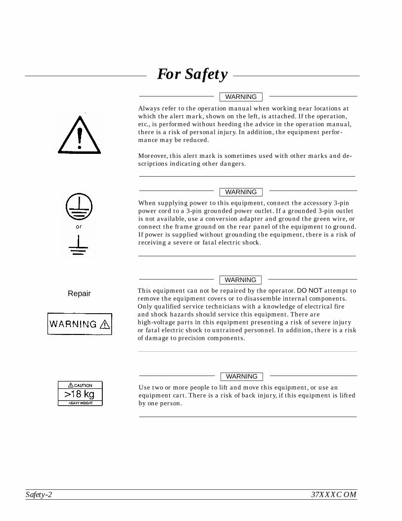
Always refer to the operation manual when working near locations atwhich the alert mark, shown on the left, is attached. If the operation,etc., is performed without heeding the advice in the operation manual,there is a risk of personal injury. In addition, the equipment perfor-mance may be reduced.
Moreover, this alert mark is sometimes used with other marks and de-scriptions indicating other dangers.
WARNING
When supplying power to this equipment, connect the accessory 3-pinpower cord to a 3-pin grounded power outlet. If a grounded 3-pin outletis not available, use a conversion adapter and ground the green wire, orconnect the frame ground on the rear panel of the equipment to ground.If power is supplied without grounding the equipment, there is a risk ofreceiving a severe or fatal electric shock.
WARNING
This equipment can not be repaired by the operator. DO NOT attempt toremove the equipment covers or to disassemble internal components.Only qualified service technicians with a knowledge of electrical fireand shock hazards should service this equipment. There arehigh-voltage parts in this equipment presenting a risk of severe injuryor fatal electric shock to untrained personnel. In addition, there is a riskof damage to precision components.
WARNING
Repair
For Safety
Use two or more people to lift and move this equipment, or use anequipment cart. There is a risk of back injury, if this equipment is liftedby one person.
WARNING
Narrative Table Of Contents
Chapter 1—General InformationThis chapter provides a general description of the Anritsu Model 37XXXC Vector Network AnalyzerSystem and its major units: network analyzer, test set, and frequency source. It also provides de-scriptions for the precision component kits, and equipment options. Additionally, it contains the list-ing of recommended test equipment.
Chapter 2—InstallationThis chapter provides instructions for performing an initial inspection, preparing the equipment foruse, setting up for operation over the IEEE-488.2 (GPIB) Bus, using a printer, and preparing theunits for storage and/or shipment. It also provides a listing of Anritsu Customer Service Centers.
Chapter 3—Network Analyzers, A PrimerThis chapter provides an introduction to network analysis and the types of measurements that canbe made using them. It provides general and introductory description.
Chapter 4—Front Panel OperationThis chapter describes the front panel controls and provides flow diagrams for the menus called upusing the front panel controls. It contains the following sub-chapters:
Front Panel Control-Group Descriptions
Calibration Keys and Indicators, Detailed Description
Save/Recall Menu Key and Menus, Key Description and Menu Flow
Measurement Keys and Menus, Key Descriptions and Menu Flow
Channel Keys and Menu, Key Descriptions and Menu Flow
Display Keys and Menus, Key Descriptions and Menu Flow
Enhancement Keys and Menus, Key Descriptions and Menu Flow
Hard Copy Keys and Menus, Key Descriptions and Menu Flow
System State Keys and Menus, Key Descriptions and Menu Flow
Markers/limits Keys and Menus, Key Descriptions and Menu Flow
Disk Storage Interface, Detailed Description
Chapter 5—Error And Status MessagesThis chapter describes the type of error messages you may encounter during operation and provides atabular listing. This listing describes and defines the error types.
Chapter 6—Data DisplaysThis chapter provides a detailed description of the various data displays. It describes the graphtypes, frequency markers, measurement limit lines, status displays, and data display controls.
37XXXC OM i
Chapter 7—Measurement CalibrationThis chapter provides a discussion and tutorial on measurement calibration. It contains step-by-stepcalibration procedures for the Standard (OSL), Offset-Short, TRM, and LRL/LRM methods. It alsohas a procedure for calibrating using a sliding termination.
Chapter 8—MeasurementsThis chapter discusses measurements with the 37XXXC VNA. It contains sub-chapters that providea detailed descriptions for Transmission and Reflection, Low Level and Gain, Group Delay, ActiveDevice, Multiple Source Control, Adapter Removal, Gain Compression, and Receiver Modemeasurements
Chapter 9—Time DomainThis chapter describes the Option 2, Time Domain feature. It provides an operational procedure anda flowchart of the time domain menus.
Chapter 10—AutoCalThis chapter describes the Automatic Calibrator (AutoCal) feature and provides operational informa-tion and procedures.
Chapter 11—Operational Checkout Procedures: 371XXCThis chapter provides a procedure for operational checkout.
Chapter 12—Operational Checkout Procedures: 372XXC, 373XXCThis chapter provides a procedure for operational checkout
Chapter 13—Calibration KitsThis chapter provides a description and listing of components for the calibration kits.
Chapter 14—Millimeter Wave SystemThis chapter contains description, operation, and checkout procedures for the millimeter wave mea-surement capability that can be added to the 371XXC Vector Network Analyzer.
Chapter 15—ME7808A Broadband Measurement SystemThis chapter contains description, operation, and checkout procedures for the optional broadbandmeasurement capability that can be added to the 37XXXC Vector Network Analyzer.
Appendix A—Front Panel Menus, Alphabetical ListingThis appendix shows all of the menus that are called up using the front panel controls. It provides areplica of the menu and descriptive text for all of the various menu choices. The listing is alphabeti-cal by the menu call letters mentioned and/or illustrated in Chapter 4.
Appendix B—Model 37XXXC VNA Rear Panel ConnectorsThis appendix describes the rear panel connectors. It also provides pinout listing.
Appendix C—Performance SpecificationsThis appendix contains the Technical Data Sheet, part number 11410-00247, which provides perfor-mance specifications.
Subject Index
ii 37XXXC OM
Narrative Table of Contents (Continued)
Table of Contents
Chapter 1 General Information
1-1 SCOPE OF MANUAL . . . . . . . . . . . . . . . . . . . . . . . . . . . . . . . . . 1-3
1-2 INTRODUCTION . . . . . . . . . . . . . . . . . . . . . . . . . . . . . . . . . . . 1-3
1-3 IDENTIFICATION NUMBER. . . . . . . . . . . . . . . . . . . . . . . . . . . . . 1-3
1-4 ONLINE MANUALS. . . . . . . . . . . . . . . . . . . . . . . . . . . . . . . . . . 1-3
1-5 SYSTEM DESCRIPTION . . . . . . . . . . . . . . . . . . . . . . . . . . . . . . . 1-3
371XXC . . . . . . . . . . . . . . . . . . . . . . . . . . . . . . . . . . . . . . . 1-4
372XXC . . . . . . . . . . . . . . . . . . . . . . . . . . . . . . . . . . . . . . . 1-4
373XXC . . . . . . . . . . . . . . . . . . . . . . . . . . . . . . . . . . . . . . . 1-4
1-6 MILLIMETER WAVE MEASUREMENTS . . . . . . . . . . . . . . . . . . . . . . 1-5
1-7 PRECISION COMPONENT KITS . . . . . . . . . . . . . . . . . . . . . . . . . . 1-5
Model 3650 SMA/3.5 mm Calibration Kit . . . . . . . . . . . . . . . . . . . . . 1-5
Model 3651 GPC–7 Calibration Kit . . . . . . . . . . . . . . . . . . . . . . . . 1-6
Model 3652 K Connector Calibration Kit . . . . . . . . . . . . . . . . . . . . . 1-7
Model 3653 Type N Calibration Kit . . . . . . . . . . . . . . . . . . . . . . . . 1-8
Model 3654B V Connector® Calibration Kit . . . . . . . . . . . . . . . . . . . . 1-9
Model 3656 W1 Connector Calibration Kit . . . . . . . . . . . . . . . . . . . . 1-10
Model 3666 3.5 mm Verification Kit . . . . . . . . . . . . . . . . . . . . . . . 1-11
Model 3667 GPC–7 Verification Kit. . . . . . . . . . . . . . . . . . . . . . . . 1-12
Model 3668 K Connector® Verification Kit . . . . . . . . . . . . . . . . . . . . 1-13
Model 3669/3669B V Connector® Verification Kits . . . . . . . . . . . . . . . 1-14
1-8 OPTIONS . . . . . . . . . . . . . . . . . . . . . . . . . . . . . . . . . . . . . . . 1-15
1-9 PERFORMANCE SPECIFICATIONS . . . . . . . . . . . . . . . . . . . . . . . . 1-15
1-10 PREVENTIVE MAINTENANCE . . . . . . . . . . . . . . . . . . . . . . . . . . 1-15
Chapter 2 Installation
2-1 INTRODUCTION . . . . . . . . . . . . . . . . . . . . . . . . . . . . . . . . . . . 2-3
2-2 INITIAL INSPECTION . . . . . . . . . . . . . . . . . . . . . . . . . . . . . . . . 2-3
2-3 PREPARATION FOR USE . . . . . . . . . . . . . . . . . . . . . . . . . . . . . . 2-3
Option 4, External SCSI Drive Setup . . . . . . . . . . . . . . . . . . . . . . . 2-4
37XXXC OM iii
2-4 GPIB SETUP . . . . . . . . . . . . . . . . . . . . . . . . . . . . . . . . . . . . . 2-5
Interface Connector . . . . . . . . . . . . . . . . . . . . . . . . . . . . . . . . . 2-5
Cable Length Restrictions . . . . . . . . . . . . . . . . . . . . . . . . . . . . . 2-5
2-5 SYSTEM GPIB INTERCONNECTION. . . . . . . . . . . . . . . . . . . . . . . . 2-6
GPIB Interface to an External Plotter . . . . . . . . . . . . . . . . . . . . . . . 2-6
GPIB Addresses . . . . . . . . . . . . . . . . . . . . . . . . . . . . . . . . . . . 2-6
2-6 EXTERNAL MONITOR CONNECTOR . . . . . . . . . . . . . . . . . . . . . . . 2-6
2-7 RACK MOUNT. . . . . . . . . . . . . . . . . . . . . . . . . . . . . . . . . . . . . 2-6
2-8 STORAGE OR SHIPMENT . . . . . . . . . . . . . . . . . . . . . . . . . . . . . . 2-9
Preparation for Storage . . . . . . . . . . . . . . . . . . . . . . . . . . . . . . . 2-9
Preparation for Shipment. . . . . . . . . . . . . . . . . . . . . . . . . . . . . . 2-9
2-9 SERVICE CENTERS . . . . . . . . . . . . . . . . . . . . . . . . . . . . . . . . . 2-10
Chapter 3 Network Analyzers, A Primer
3-1 INTRODUCTION . . . . . . . . . . . . . . . . . . . . . . . . . . . . . . . . . . . 3-3
3-2 GENERAL DESCRIPTION . . . . . . . . . . . . . . . . . . . . . . . . . . . . . . 3-3
Source Module. . . . . . . . . . . . . . . . . . . . . . . . . . . . . . . . . . . . 3-4
Test Set Module . . . . . . . . . . . . . . . . . . . . . . . . . . . . . . . . . . . 3-4
Analyzer Module . . . . . . . . . . . . . . . . . . . . . . . . . . . . . . . . . . 3-4
3-3 NETWORK ANALYZERS . . . . . . . . . . . . . . . . . . . . . . . . . . . . . . . 3-5
Chapter 4 Front Panel Operation
4-1 INTRODUCTION . . . . . . . . . . . . . . . . . . . . . . . . . . . . . . . . . . . 4-3
4-2 KEY-GROUPS . . . . . . . . . . . . . . . . . . . . . . . . . . . . . . . . . . . . . 4-3
4-3 CALIBRATION KEY-GROUP . . . . . . . . . . . . . . . . . . . . . . . . . . . . 4-11
4-4 SAVE/RECALL MENU KEY . . . . . . . . . . . . . . . . . . . . . . . . . . . . . 4-21
4-5 MEASUREMENT KEY-GROUP . . . . . . . . . . . . . . . . . . . . . . . . . . 4-22
4-6 CHANNELS KEY-GROUP . . . . . . . . . . . . . . . . . . . . . . . . . . . . . . 4-25
4-7 DISPLAY KEY-GROUP . . . . . . . . . . . . . . . . . . . . . . . . . . . . . . . 4-26
4-8 ENHANCEMENT KEY-GROUP. . . . . . . . . . . . . . . . . . . . . . . . . . . 4-30
4-9 HARD COPY KEY-GROUP . . . . . . . . . . . . . . . . . . . . . . . . . . . . . 4-32
4-10 SYSTEM STATE KEY-GROUP . . . . . . . . . . . . . . . . . . . . . . . . . . . 4-34
4-11 MARKERS/LIMITS KEY-GROUP . . . . . . . . . . . . . . . . . . . . . . . . . . 4-37
iv 37XXXC OM
Table of Contents (Continued)
4-12 DISK STORAGE INTERFACE . . . . . . . . . . . . . . . . . . . . . . . . . . . 4-41
Disk Format . . . . . . . . . . . . . . . . . . . . . . . . . . . . . . . . . . . . 4-41
Disk Files. . . . . . . . . . . . . . . . . . . . . . . . . . . . . . . . . . . . . . 4-41
Disk File Output Device . . . . . . . . . . . . . . . . . . . . . . . . . . . . . . 4-42
Formatting a Data File Disk . . . . . . . . . . . . . . . . . . . . . . . . . . . 4-42
Copying Data Files From Disk to Disk . . . . . . . . . . . . . . . . . . . . . . 4-42
Recovering From Disk Write/Read Errors . . . . . . . . . . . . . . . . . . . . 4-42
4-13 COMMAND LINE . . . . . . . . . . . . . . . . . . . . . . . . . . . . . . . . . . 4-43
Create Directory . . . . . . . . . . . . . . . . . . . . . . . . . . . . . . . . . . 4-43
List Directory . . . . . . . . . . . . . . . . . . . . . . . . . . . . . . . . . . . 4-43
Change Directory . . . . . . . . . . . . . . . . . . . . . . . . . . . . . . . . . 4-43
Delete Files. . . . . . . . . . . . . . . . . . . . . . . . . . . . . . . . . . . . . 4-43
Remove Directory . . . . . . . . . . . . . . . . . . . . . . . . . . . . . . . . . 4-44
Copy Files . . . . . . . . . . . . . . . . . . . . . . . . . . . . . . . . . . . . . 4-44
Conventions . . . . . . . . . . . . . . . . . . . . . . . . . . . . . . . . . . . . 4-44
Chapter 5 Error and Status Messages
5-1 INTRODUCTION . . . . . . . . . . . . . . . . . . . . . . . . . . . . . . . . . . . 5-3
5-2 ERROR MESSAGES. . . . . . . . . . . . . . . . . . . . . . . . . . . . . . . . . . 5-3
Chapter 6 Data Displays
6-1 INTRODUCTION . . . . . . . . . . . . . . . . . . . . . . . . . . . . . . . . . . . 6-3
6-2 DISPLAY MODES AND TYPES . . . . . . . . . . . . . . . . . . . . . . . . . . . 6-3
Single Channel Display: Ch 1, 2, 3, 4. . . . . . . . . . . . . . . . . . . . . . . . 6-3
Dual Channel Display: Ch 1 and 3 or Ch 2 and 4 . . . . . . . . . . . . . . . . . 6-4
Four Channel Display: Ch 1, 2, 3, 4 . . . . . . . . . . . . . . . . . . . . . . . . 6-5
Dual Trace Overlay . . . . . . . . . . . . . . . . . . . . . . . . . . . . . . . . . 6-6
Graph Data Types. . . . . . . . . . . . . . . . . . . . . . . . . . . . . . . . . . 6-7
6-3 FREQUENCY MARKERS . . . . . . . . . . . . . . . . . . . . . . . . . . . . . . 6-11
Marker Designation . . . . . . . . . . . . . . . . . . . . . . . . . . . . . . . . 6-11
6-4 LIMITS . . . . . . . . . . . . . . . . . . . . . . . . . . . . . . . . . . . . . . . . 6-11
37XXXC OM v
Table of Contents (Continued)
6-5 STATUS DISPLAY . . . . . . . . . . . . . . . . . . . . . . . . . . . . . . . . . . 6-12
Reference Position Marker . . . . . . . . . . . . . . . . . . . . . . . . . . . . 6-12
Scale Resolution . . . . . . . . . . . . . . . . . . . . . . . . . . . . . . . . . . 6-12
Frequency Range . . . . . . . . . . . . . . . . . . . . . . . . . . . . . . . . . 6-12
Analog Instrument Status. . . . . . . . . . . . . . . . . . . . . . . . . . . . . 6-12
Measurement Status . . . . . . . . . . . . . . . . . . . . . . . . . . . . . . . 6-13
Sweep Indicator Marker . . . . . . . . . . . . . . . . . . . . . . . . . . . . . . 6-13
6-6 DATA DISPLAY CONTROL . . . . . . . . . . . . . . . . . . . . . . . . . . . . . 6-13
S-parameter Selection . . . . . . . . . . . . . . . . . . . . . . . . . . . . . . . 6-14
Data Display Update . . . . . . . . . . . . . . . . . . . . . . . . . . . . . . . 6-14
Display of Markers. . . . . . . . . . . . . . . . . . . . . . . . . . . . . . . . . 6-14
6-7 HARD COPY AND DISK OUTPUT . . . . . . . . . . . . . . . . . . . . . . . . . 6-15
Tabular Printout . . . . . . . . . . . . . . . . . . . . . . . . . . . . . . . . . . 6-15
Screen-Image Printout . . . . . . . . . . . . . . . . . . . . . . . . . . . . . . 6-15
Plotter Output . . . . . . . . . . . . . . . . . . . . . . . . . . . . . . . . . . . 6-15
Disk Output . . . . . . . . . . . . . . . . . . . . . . . . . . . . . . . . . . . . 6-15
Chapter 7 Measurement Calibration
7-1 INTRODUCTION . . . . . . . . . . . . . . . . . . . . . . . . . . . . . . . . . . . 7-3
7-2 DISCUSSION . . . . . . . . . . . . . . . . . . . . . . . . . . . . . . . . . . . . . 7-3
Establishing the Test Ports . . . . . . . . . . . . . . . . . . . . . . . . . . . . . 7-3
Understanding the Calibration System . . . . . . . . . . . . . . . . . . . . . . 7-5
Calibrating for a Measurement . . . . . . . . . . . . . . . . . . . . . . . . . . 7-9
Evaluating the Calibration . . . . . . . . . . . . . . . . . . . . . . . . . . . . 7-11
Verification Kits . . . . . . . . . . . . . . . . . . . . . . . . . . . . . . . . . . 7-11
7-3 SLIDING TERMINATION . . . . . . . . . . . . . . . . . . . . . . . . . . . . . . 7-13
7-4 SOLT CALIBRATION . . . . . . . . . . . . . . . . . . . . . . . . . . . . . . . . 7-19
7-5 OFFSET-SHORT CALIBRATION (SSLT) . . . . . . . . . . . . . . . . . . . . . . 7-28
7-6 TRIPLE OFFSET-SHORT CALIBRATION (SSST) . . . . . . . . . . . . . . . . . 7-32
7-7 LRL/LRM CALIBRATION . . . . . . . . . . . . . . . . . . . . . . . . . . . . . . 7-36
7-8 TRM CALIBRATION . . . . . . . . . . . . . . . . . . . . . . . . . . . . . . . . . 7-46
7-9 MERGE CAL FILES APPLICATION . . . . . . . . . . . . . . . . . . . . . . . . 7-47
vi 37XXXC OM
Table of Contents (Continued)

Chapter 8 Measurements
8-1 INTRODUCTION . . . . . . . . . . . . . . . . . . . . . . . . . . . . . . . . . . . 8-3
8-2 TRANSMISSION AND REFLECTION . . . . . . . . . . . . . . . . . . . . . . . . 8-3
8-3 LOW LEVEL AND GAIN . . . . . . . . . . . . . . . . . . . . . . . . . . . . . . 8-12
8-4 GROUP DELAY . . . . . . . . . . . . . . . . . . . . . . . . . . . . . . . . . . . 8-20
8-5 ACTIVE DEVICE . . . . . . . . . . . . . . . . . . . . . . . . . . . . . . . . . . 8-24
8-6 MULTIPLE SOURCE CONTROL . . . . . . . . . . . . . . . . . . . . . . . . . . 8-29
Control Formula . . . . . . . . . . . . . . . . . . . . . . . . . . . . . . . . . . 8-29
8-7 ADAPTER REMOVAL . . . . . . . . . . . . . . . . . . . . . . . . . . . . . . . . 8-34
8-8 GAIN COMPRESSION. . . . . . . . . . . . . . . . . . . . . . . . . . . . . . . . 8-39
Power and VNAs . . . . . . . . . . . . . . . . . . . . . . . . . . . . . . . . . . 8-39
Swept Power Gain Compression . . . . . . . . . . . . . . . . . . . . . . . . . 8-41
Swept Frequency Gain Compression . . . . . . . . . . . . . . . . . . . . . . . 8-41
8-9 RECEIVER MODE . . . . . . . . . . . . . . . . . . . . . . . . . . . . . . . . . . 8-58
Source Lock Mode . . . . . . . . . . . . . . . . . . . . . . . . . . . . . . . . . 8-58
Tracking Mode . . . . . . . . . . . . . . . . . . . . . . . . . . . . . . . . . . . 8-58
Set-on Mode . . . . . . . . . . . . . . . . . . . . . . . . . . . . . . . . . . . . 8-58
Receiver Mode Block Diagram . . . . . . . . . . . . . . . . . . . . . . . . . . 8-59
Receiver Mode Menus . . . . . . . . . . . . . . . . . . . . . . . . . . . . . . . 8-59
Procedure, Receiver Mode Operation . . . . . . . . . . . . . . . . . . . . . . . 8-59
8-10 OPTICAL APPLICATION . . . . . . . . . . . . . . . . . . . . . . . . . . . . . . 8-62
E/O Measurements . . . . . . . . . . . . . . . . . . . . . . . . . . . . . . . . 8-62
O/E Measurements . . . . . . . . . . . . . . . . . . . . . . . . . . . . . . . . 8-65
Creating a Characterization (*.S2P) File for E/O and O/E Measurements . . . 8-71
Chapter 9 Time Domain
9-1 INTRODUCTION . . . . . . . . . . . . . . . . . . . . . . . . . . . . . . . . . . . 9-3
9-2 TIME DOMAIN MEASUREMENTS . . . . . . . . . . . . . . . . . . . . . . . . . 9-3
9-3 OPERATING TIME DOMAIN . . . . . . . . . . . . . . . . . . . . . . . . . . . . 9-8
9-4 WINDOWING. . . . . . . . . . . . . . . . . . . . . . . . . . . . . . . . . . . . . 9-11
9-5 GATING. . . . . . . . . . . . . . . . . . . . . . . . . . . . . . . . . . . . . . . . 9-12
9-6 ANTI-GATING . . . . . . . . . . . . . . . . . . . . . . . . . . . . . . . . . . . . 9-14
9-7 EXAMPLES, GATING AND ANTI-GATING . . . . . . . . . . . . . . . . . . . . 9-14
37XXXC OM vii
Table of Contents (Continued)

9-8 TIME DOMAIN MENUS. . . . . . . . . . . . . . . . . . . . . . . . . . . . . . . 9-14
Chapter 10 AutoCal
10-1 INTRODUCTION. . . . . . . . . . . . . . . . . . . . . . . . . . . . . . . . . . . 10-3
10-2 DESCRIPTION . . . . . . . . . . . . . . . . . . . . . . . . . . . . . . . . . . . . 10-3
10-3 CALIBRATIONS . . . . . . . . . . . . . . . . . . . . . . . . . . . . . . . . . . . 10-4
10-4 DEFINITIONS . . . . . . . . . . . . . . . . . . . . . . . . . . . . . . . . . . . . 10-4
10-5 PHYSICAL SETUP. . . . . . . . . . . . . . . . . . . . . . . . . . . . . . . . . . 10-6
10-6 CHARACTERIZATION FILES . . . . . . . . . . . . . . . . . . . . . . . . . . . 10-7
10-7 USING AUTOCAL . . . . . . . . . . . . . . . . . . . . . . . . . . . . . . . . . . 10-9
10-8 PIN DEPTH SPECIFICATIONS . . . . . . . . . . . . . . . . . . . . . . . . . . 10-13
10-9 AUTOCAL MENUS FLOW DIAGRAM . . . . . . . . . . . . . . . . . . . . . . 10-14
Chapter 11 Operational Checkout Procedures: 371XXC
11-1 INTRODUCTION. . . . . . . . . . . . . . . . . . . . . . . . . . . . . . . . . . . 11-3
11-2 REQUIRED EQUIPMENT. . . . . . . . . . . . . . . . . . . . . . . . . . . . . . 11-3
11-3 INITIAL SETUP . . . . . . . . . . . . . . . . . . . . . . . . . . . . . . . . . . . 11-3
11-4 SELF TEST . . . . . . . . . . . . . . . . . . . . . . . . . . . . . . . . . . . . . . 11-3
11-5 SAMPLER EFFICIENCY TEST . . . . . . . . . . . . . . . . . . . . . . . . . . . 11-4
11-6 HIGH LEVEL NOISE TEST . . . . . . . . . . . . . . . . . . . . . . . . . . . . . 11-8
Chapter 12 Operational Checkout Procedures: 372XXC, 373XXC
12-1 INTRODUCTION. . . . . . . . . . . . . . . . . . . . . . . . . . . . . . . . . . . 12-3
12-2 REQUIRED EQUIPMENT. . . . . . . . . . . . . . . . . . . . . . . . . . . . . . 12-3
12-3 INITIAL SETUP . . . . . . . . . . . . . . . . . . . . . . . . . . . . . . . . . . . 12-3
12-4 SELF TEST . . . . . . . . . . . . . . . . . . . . . . . . . . . . . . . . . . . . . . 12-3
12-5 NON-RATIO POWER . . . . . . . . . . . . . . . . . . . . . . . . . . . . . . . . 12-4
12-6 HIGH LEVEL NOISE TEST . . . . . . . . . . . . . . . . . . . . . . . . . . . . . 12-6
Chapter 13 Calibration Kits
13-1 INTRODUCTION. . . . . . . . . . . . . . . . . . . . . . . . . . . . . . . . . . . 13-3
13-2 PURPOSE. . . . . . . . . . . . . . . . . . . . . . . . . . . . . . . . . . . . . . . 13-3
viii 37XXXC OM
Table of Contents (Continued)
13-3 KIT CONTENTS . . . . . . . . . . . . . . . . . . . . . . . . . . . . . . . . . . . 13-3
Model 3650 Calibration Kit . . . . . . . . . . . . . . . . . . . . . . . . . . . . 13-4
Model 3651 Calibration Kit . . . . . . . . . . . . . . . . . . . . . . . . . . . . 13-5
Model 3652 Calibration Kit . . . . . . . . . . . . . . . . . . . . . . . . . . . . 13-6
Model 3653 Calibration Kit . . . . . . . . . . . . . . . . . . . . . . . . . . . . 13-7
Model 3654/ 3654B Calibration Kit . . . . . . . . . . . . . . . . . . . . . . . . 13-8
Model 3656 Calibration Kit . . . . . . . . . . . . . . . . . . . . . . . . . . . . 13-9
13-4 PRECAUTIONS . . . . . . . . . . . . . . . . . . . . . . . . . . . . . . . . . . . 13-10
Pin Depth . . . . . . . . . . . . . . . . . . . . . . . . . . . . . . . . . . . . . 13-10
Pin Depth Tolerance . . . . . . . . . . . . . . . . . . . . . . . . . . . . . . . 13-11
Over Torquing Connectors . . . . . . . . . . . . . . . . . . . . . . . . . . . . 13-11
Teflon Tuning Washers. . . . . . . . . . . . . . . . . . . . . . . . . . . . . . 13-11
Mechanical Shock . . . . . . . . . . . . . . . . . . . . . . . . . . . . . . . . 13-11
13-5 CLEANING INSTRUCTIONS . . . . . . . . . . . . . . . . . . . . . . . . . . . 13-12
Chapter 14 Millimeter Wave System
14-1 INTRODUCTION. . . . . . . . . . . . . . . . . . . . . . . . . . . . . . . . . . . 14-3
14-2 DESCRIPTION . . . . . . . . . . . . . . . . . . . . . . . . . . . . . . . . . . . . 14-3
14-3 PERFORMANCE SPECIFICATIONS . . . . . . . . . . . . . . . . . . . . . . . . 14-4
System Performance . . . . . . . . . . . . . . . . . . . . . . . . . . . . . . . . 14-4
Test Port Characteristics . . . . . . . . . . . . . . . . . . . . . . . . . . . . . 14-5
Measurement Capabilities . . . . . . . . . . . . . . . . . . . . . . . . . . . . 14-5
14-4 INSTALLATION . . . . . . . . . . . . . . . . . . . . . . . . . . . . . . . . . . . 14-6
14-5 CONTROLS AND CONNECTORS . . . . . . . . . . . . . . . . . . . . . . . . . 14-11
14-6 CALIBRATION . . . . . . . . . . . . . . . . . . . . . . . . . . . . . . . . . . . 14-13
14-7 OPERATION . . . . . . . . . . . . . . . . . . . . . . . . . . . . . . . . . . . . 14-14
Entering/ Leaving Millimeter Wave Operation . . . . . . . . . . . . . . . . . 14-14
Changing Bands/Modules While in Millimeter Wave. . . . . . . . . . . . . . 14-18
Allowable Millimeter Wave Module Configurations, Measurements andCalibrations. . . . . . . . . . . . . . . . . . . . . . . . . . . . . . . . . . . . 14-18
Effect of Default Program . . . . . . . . . . . . . . . . . . . . . . . . . . . . 14-19
Redefinition of Band Frequency Ranges . . . . . . . . . . . . . . . . . . . . 14-20
Use of Normal Multiple Source Mode . . . . . . . . . . . . . . . . . . . . . . 14-21
Stored Setups and Calibrations . . . . . . . . . . . . . . . . . . . . . . . . . 14-21
External Source and Power Levels . . . . . . . . . . . . . . . . . . . . . . . 14-22
37XXXC OM ix
Table of Contents (Continued)
14-8 MEASUREMENT PROCEDURE. . . . . . . . . . . . . . . . . . . . . . . . . . 14-23
14-9 REMOTE OPERATION. . . . . . . . . . . . . . . . . . . . . . . . . . . . . . . 14-24
14-10 OPERATIONAL CHECKOUT— GENERAL . . . . . . . . . . . . . . . . . . . 14-25
14-11 OPERATION CHECKOUT—IF POWER LEVEL TEST . . . . . . . . . . . . . 14-26
14-12 OPERATIONAL CHECKOUT— TRANSMISSION HIGH LEVEL NOISE TEST14-28
14-13 OPERATIONAL CHECKOUT— REFLECTION HIGH LEVEL NOISE TEST . 14-30
Chapter 15 ME7808A Broadband Measurement System
15-1 INTRODUCTION. . . . . . . . . . . . . . . . . . . . . . . . . . . . . . . . . . . 15-3
15-2 SYSTEM DESCRIPTION . . . . . . . . . . . . . . . . . . . . . . . . . . . . . . 15-3
Measurement Instruments . . . . . . . . . . . . . . . . . . . . . . . . . . . . 15-3
Console and Associated Hardware . . . . . . . . . . . . . . . . . . . . . . . . 15-4
Cables . . . . . . . . . . . . . . . . . . . . . . . . . . . . . . . . . . . . . . . 15-4
15-3 INSTALLATION . . . . . . . . . . . . . . . . . . . . . . . . . . . . . . . . . . . 15-4
Console and Table Setup . . . . . . . . . . . . . . . . . . . . . . . . . . . . . 15-5
Instrument Installation into Console . . . . . . . . . . . . . . . . . . . . . . . 15-6
System Cabling . . . . . . . . . . . . . . . . . . . . . . . . . . . . . . . . . . 15-9
15-4 INITIAL ELECTRICAL TESTS . . . . . . . . . . . . . . . . . . . . . . . . . . 15-11
Millimeter Module Checkout. . . . . . . . . . . . . . . . . . . . . . . . . . . 15-11
40 MHz to 65 GHz Checkout. . . . . . . . . . . . . . . . . . . . . . . . . . . 15-12
15-5 WAFER PROBE STATION . . . . . . . . . . . . . . . . . . . . . . . . . . . . 15-13
15-6 BROADBAND MENUS, FLOW. . . . . . . . . . . . . . . . . . . . . . . . . . . 15-15
15-7 BROADBAND CALIBRATION . . . . . . . . . . . . . . . . . . . . . . . . . . . 15-16
Merging Calibrations. . . . . . . . . . . . . . . . . . . . . . . . . . . . . . . 15-16
x 37XXXC OM
Table of Contents (Continued)
Appendix A Front Panel Menus, Alphabetical Listing
Appendix B Rear Panel Connectors
Appendix C Performance Specifications
Subject Index
Table of Contents
1-1 SCOPE OF MANUAL . . . . . . . . . . . . . . . . . . . . . . . . . . . . . . . . . 1-3
1-2 INTRODUCTION . . . . . . . . . . . . . . . . . . . . . . . . . . . . . . . . . . . 1-3
1-3 IDENTIFICATION NUMBER. . . . . . . . . . . . . . . . . . . . . . . . . . . . . 1-3
1-4 ONLINE MANUALS. . . . . . . . . . . . . . . . . . . . . . . . . . . . . . . . . . 1-3
1-5 SYSTEM DESCRIPTION . . . . . . . . . . . . . . . . . . . . . . . . . . . . . . . 1-3
371XXC . . . . . . . . . . . . . . . . . . . . . . . . . . . . . . . . . . . . . . . 1-4
372XXC . . . . . . . . . . . . . . . . . . . . . . . . . . . . . . . . . . . . . . . 1-4
373XXC . . . . . . . . . . . . . . . . . . . . . . . . . . . . . . . . . . . . . . . 1-4
1-6 MILLIMETER WAVE MEASUREMENTS . . . . . . . . . . . . . . . . . . . . . . 1-5
1-7 PRECISION COMPONENT KITS . . . . . . . . . . . . . . . . . . . . . . . . . . 1-5
Model 3650 SMA/3.5 mm Calibration Kit . . . . . . . . . . . . . . . . . . . . . 1-5
Model 3651 GPC–7 Calibration Kit . . . . . . . . . . . . . . . . . . . . . . . . 1-6
Model 3652 K Connector Calibration Kit . . . . . . . . . . . . . . . . . . . . . 1-7
Model 3653 Type N Calibration Kit . . . . . . . . . . . . . . . . . . . . . . . . 1-8
Model 3654B V Connector® Calibration Kit . . . . . . . . . . . . . . . . . . . . 1-9
Model 3656 W1 Connector Calibration Kit . . . . . . . . . . . . . . . . . . . . 1-10
Model 3666 3.5 mm Verification Kit . . . . . . . . . . . . . . . . . . . . . . . 1-11
Model 3667 GPC–7 Verification Kit. . . . . . . . . . . . . . . . . . . . . . . . 1-12
Model 3668 K Connector® Verification Kit . . . . . . . . . . . . . . . . . . . . 1-13
Model 3669/3669B V Connector® Verification Kits . . . . . . . . . . . . . . . 1-14
1-8 OPTIONS . . . . . . . . . . . . . . . . . . . . . . . . . . . . . . . . . . . . . . . 1-15
1-9 PERFORMANCE SPECIFICATIONS . . . . . . . . . . . . . . . . . . . . . . . . 1-15
1-10 PREVENTIVE MAINTENANCE . . . . . . . . . . . . . . . . . . . . . . . . . . 1-15
Chapter 1General Information
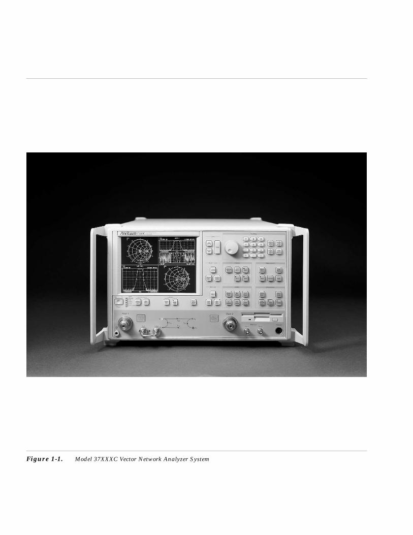
Figure 1-1. Model 37XXXC Vector Network Analyzer System
Chapter 1General Information
1-1 SCOPE OF MANUAL This manual provides general information, installation, and operatinginformation for the Model 37XXXC Vector Network Analyzer (VNA)system. (Throughout this manual, the terms VNA, 37XXXC VNA, and37XXXC will be used interchangeably to refer to the system.) It alsoprovides description and instructions for the Millimeter Wave Systemthat can be added to the 371XXC. Manual organization is shown in thetable of contents.
1-2 INTRODUCTION This section provides general information about the 37XXXC VNA sys-tem and one or more precision-component calibration or performanceverification kits. The section also provides a listing of recommendedtest equipment.
1-3 IDENTIFICATIONNUMBER
All Anritsu instruments are assigned a unique six-digit ID number,such as “940101.” This number is affixed to a decal on the rear panel ofeach unit. In any correspondence with Anritsu Customer Service,please use this number.
1-4 ONLINE MANUALS Manual updates, if any, are available on Anritsu's Internet downloadpage (http://www.us.anritsu.com/downloads/).
1-5 SYSTEM DESCRIPTION The 37XXXC Network Analyzer (Figure 1-1) is a single-instrumentsystem that contains a built-in source, test set, and analyzer. It is pro-duced in three series—371XXC, 372XXC, and 373XXC—described be-low. All models provide up to 1601 measurement data points, a built-inhard-disk drive for storing and recalling front panel setups and mea-surement and calibration data. They also provide an on-screen displayof total operational time and dates of system calibrations. They sup-port operation over the IEEE 488.2 General Purpose Interface Bus(GPIB).
37XXXC OM 1-3
371XXC The 371XXC is a direct-receiver access (DRA) VNA consisting of twomodels that cover a range from 22.5 MHz to 40 GHz. It cannot makeS-parameter measurements without the use of an externalreflectometer. See “Important Note” below.
Model Frequency Range
37147C 22.5 MHz to 20.0 GHz
37169C 22.5 MHz to 40.0 GHz
IMPORTANT NOTEThe 37100C Direct Access Receiver cannot make S-param-eter measurements without an external reflectometersetup. This manual describes calibration and S-parametermeasurements for 372XXC and 373XXC. Most of thesemeasurements can also be used with 371XXC assumingthe user understands the need for an externalreflectometer. Anritsu offers an optional reflectometer testset that can be used. This reflectometer is described and adrawing shown in the Technical Data Sheet provided asAppendix C in this manual.
372XXC The 372XXC is a fully functioning VNA for making passive-devicemeasurements. The series offers five models that cover a range from22.5 MHz to 65 GHz. The models are shown below:
Model Frequency Range
37225C 40.0 MHz to 13.5 GHz
37247C 40.0 MHz to 20.0 GHz
37269C 40.0 MHz to 40.0 GHz
37277C 40.0 MHz to 50.0 GHz
37297C 40.0 MHz to 65.0 GHz
373XXC The 373XXC is a fully functioning VNA for making passive- and ac-tive-device measurements. The series offers five models that cover arange from 22.5 MHz to 65 GHz. The models are shown below.
Model Frequency Range
37325C 40.0 MHz to 13.5 GHz
37347C 40.0 MHz to 20.0 GHz
37369C 40.0 MHz to 40.0 GHz
37377C 40.0 MHz to 50.0 GHz
37397C 40.0 MHz to 65.0 GHz
SYSTEM DESCRIPTION GENERAL INFORMATION
1-4 37XXXC OM

1-6 MILLIMETER WAVEMEASUREMENTS
The 371XXC can be equipped for making millimeter wave measure-ments. A description of this measurement mode is provided inChapter 14.
1-7 PRECISION COMPONENTKITS
Two types of precision-component kits are available: calibration andverification. Calibration kits contain components used to identify andseparate error sources inherent in microwave test setups. Verificationkits consist of components with characteristics traceable to theNational Institute of Standards and Technology (NIST). This type ofkit is usually kept in the metrology laboratory where it provides themost dependable means of checking system accuracy. Each of thesekits contains a micro-floppy disk providing coefficient or measurementdata for each component. Details of these kits are described in the fol-lowing paragraphs.
Model 3650 SMA/3.5 mmCalibration Kit
The 3650 Calibration Kit (Figure 1-2) contains all the precisioncomponents and tools required to calibrate the 37XXXC VNA for12-term error-corrected measurements of test devices with SMA or3.5 mm connectors. Components are included for calibrating both maleand female test ports. The kit supports calibration with broadbandloads. The kit consists of the following components:
23S50 Short, SMA/3.5 mm Male
23SF50 Short, SMA/3.5 mm Female
24S50 Open, SMA/3.5 mm Male
24SF50 Open, SMA/3.5 mm Female
28S50–2 Termination, SMA/3.5 mm Male, 2 ea. (dc–26.5 GHz)
28SF50–2 Termination, SMA/3.5 mm Female, 2 ea.(dc–26.5 GHz)
33SFSF50 Insertable, SMA/3.5 mm Female/Female, 2 ea.
33SS50 Insertable, SMA/3.5 mm Male/Male
33SSF50 Insertable, SMA/3.5 mm Male/Female, 2 ea.
34AS50–2 Adapter, GPC–7 to SMA/3.5 mm Male, 2 ea.
34ASF50-2 Adapter, GPC–7 to SMA/3.5 mm Female, 2 ea.
01–201 Torque Wrench
01–210 Reference Flat
01–222 Connector Gauge
01–223 Gauge Kit Adapter
Data Disk
Option 1: Adds 17S50 Sliding Load, SMA/3.5 mm Male; 17SF50Sliding Load, SMA/3.5 mm Female; 01–211 Female Flush Short; and01–212 Male Flush Short.
37XXXC OM 1-5
GENERAL INFORMATION MILLIMETER WAVEMEASUREMENTS
Figure 1-2. Typical Model 365XCalibration Kit
Model 3651 GPC–7Calibration Kit
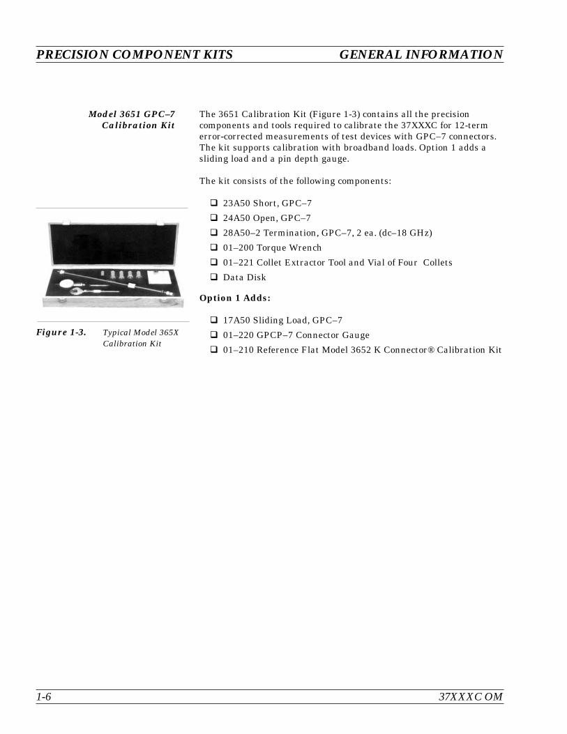
The 3651 Calibration Kit (Figure 1-3) contains all the precisioncomponents and tools required to calibrate the 37XXXC for 12-termerror-corrected measurements of test devices with GPC–7 connectors.The kit supports calibration with broadband loads. Option 1 adds asliding load and a pin depth gauge.
The kit consists of the following components:
23A50 Short, GPC–7
24A50 Open, GPC–7
28A50–2 Termination, GPC–7, 2 ea. (dc–18 GHz)
01–200 Torque Wrench
01–221 Collet Extractor Tool and Vial of Four Collets
Data Disk
Option 1 Adds:
17A50 Sliding Load, GPC–7
01–220 GPCP–7 Connector Gauge
01–210 Reference Flat Model 3652 K Connector® Calibration Kit
PRECISION COMPONENT KITS GENERAL INFORMATION
1-6 37XXXC OM
Figure 1-3. Typical Model 365XCalibration Kit
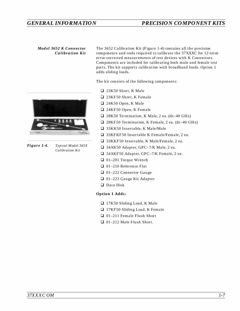
Model 3652 K ConnectorCalibration Kit
The 3652 Calibration Kit (Figure 1-4) contains all the precisioncomponents and tools required to calibrate the 37XXXC for 12-termerror-corrected measurements of test devices with K Connectors.Components are included for calibrating both male and female testports. The kit supports calibration with broadband loads. Option 1adds sliding loads.
The kit consists of the following components:
23K50 Short, K Male
23KF50 Short, K Female
24K50 Open, K Male
24KF50 Open, K Female
28K50 Termination, K Male, 2 ea. (dc–40 GHz)
28KF50 Termination, K Female, 2 ea. (dc–40 GHz)
33KK50 Insertable, K Male/Male
33KFKF50 Insertable K Female/Female, 2 ea.
33KKF50 Insertable, K Male/Female, 2 ea.
34AK50 Adapter, GPC–7/K Male, 2 ea.
34AKF50 Adapter, GPC–7/K Female, 2 ea.
01–201 Torque Wrench
01–210 Reference Flat
01–222 Connector Gauge
01–223 Gauge Kit Adapter
Data Disk
Option 1 Adds:
17K50 Sliding Load, K Male
17KF50 Sliding Load, K Female
01–211 Female Flush Short
01–212 Male Flush Short.
37XXXC OM 1-7
GENERAL INFORMATION PRECISION COMPONENT KITS
Figure 1-4. Typical Model 365XCalibration Kit

Model 3653 Type NCalibration Kit
The 3653 Calibration Kit (Figure 1-5) contains all the precisioncomponents and tools required to calibrate the 37XXXC for 12-termerror-corrected measurements of test devices with Type N connectors.Components are included for calibrating both male and female testports. The kit supports calibration with broadband loads. Option 1 forsliding loads is not available in this calibration kit.
The kit consists of the following components:
23N50 Short, N Male
23NF50 Short, N Female
24N50 Open, N Male
24NF50 Open, N Female
28N50–2 Termination, N Male, 2 ea. (dc–18 GHz)
28NF50–2 Termination, N Female, 2 ea. (dc–18 GHz)
34AN50–2 Adapter, GPC–7/N Male, 2 ea.
34ANF50–2 Adapter, GPC–7/N Female, 2 ea.
01–213 Type N Reference Gauge
01–224 Type N Connector Gauge
Data Disk Model 3654B
PRECISION COMPONENT KITS GENERAL INFORMATION
1-8 37XXXC OM
Figure 1-5. Typical Model 365XCalibration Kit
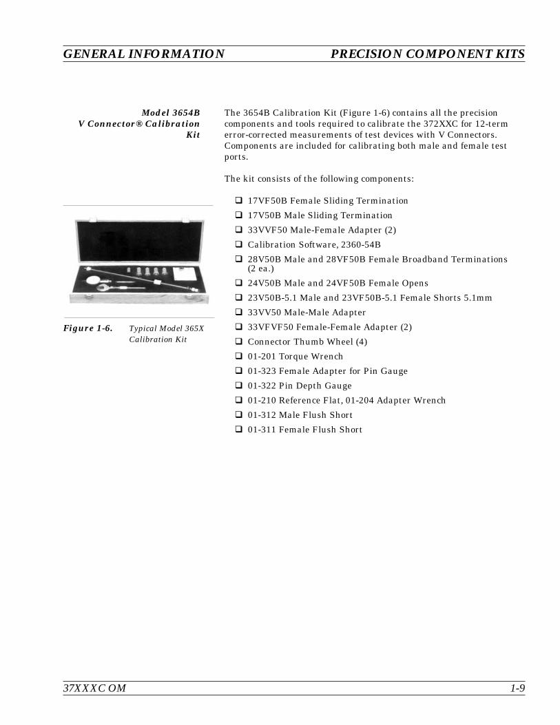
Model 3654BV Connector® Calibration
Kit
The 3654B Calibration Kit (Figure 1-6) contains all the precisioncomponents and tools required to calibrate the 372XXC for 12-termerror-corrected measurements of test devices with V Connectors.Components are included for calibrating both male and female testports.
The kit consists of the following components:
17VF50B Female Sliding Termination
17V50B Male Sliding Termination
33VVF50 Male-Female Adapter (2)
Calibration Software, 2360-54B
28V50B Male and 28VF50B Female Broadband Terminations(2 ea.)
24V50B Male and 24VF50B Female Opens
23V50B-5.1 Male and 23VF50B-5.1 Female Shorts 5.1mm
33VV50 Male-Male Adapter
33VFVF50 Female-Female Adapter (2)
Connector Thumb Wheel (4)
01-201 Torque Wrench
01-323 Female Adapter for Pin Gauge
01-322 Pin Depth Gauge
01-210 Reference Flat, 01-204 Adapter Wrench
01-312 Male Flush Short
01-311 Female Flush Short
37XXXC OM 1-9
GENERAL INFORMATION PRECISION COMPONENT KITS
Figure 1-6. Typical Model 365XCalibration Kit

Model 3656 W1 ConnectorCalibration Kit
The 3656 W1 (1.0 mm) Connector Calibration Kit (Figure 1-7) consistsof precision components to calibrate the VNA to 110 GHz. The kit sup-ports SOLT calibrations with opens, shorts, and loads to 65 GHz, andTriple Offset short calibrations from 65 GHz to 110 GHz. The kit alsoincludes verification devices for determining system accuracy of theVNA. A diskette containing factory measured test data is supplied forcomparison with customer measured data.
23W50-1, Male Offset Short 2.02 mm
23WF50-1, Female Offset Short 2.02 mm
23W50-2, Male Offset Short 2.65 mm
23WF50-2, Female Offset Short 2.65 mm
23W50-3, Male Offset Short 3.180 mm
23WF50-3, Female Offset Short 3.180 mm
24W50, Male Open 1.510 mm
24WF50, Female Open 1.930 mm
28W50, Male Broadband Termination
28WF50, Female Broadband Termination
33WW50, Male-Male Adapter (1)
33WWF50, Male-Female Adapter (1)
33WFWF50, Female-Female Adapter (1)
01-401, Interchangeable Adapter Fixed Female
01-402, Interchangeable Adapter Fixed Male
18WWF50-1, 50 Matched Thruline (Verification Device)
18WWF50-1B, Stepped Impedance Thruline (Verification Device)
01-504, Torque Wrench
01-505, End Wrench
Calibration coefficients diskette
Verification kit diskette
1-10 37XXXC OM
PRECISION COMPONENT KITS GENERAL INFORMATION
Figure 1-7. Typical Model 3656Calibration Kit
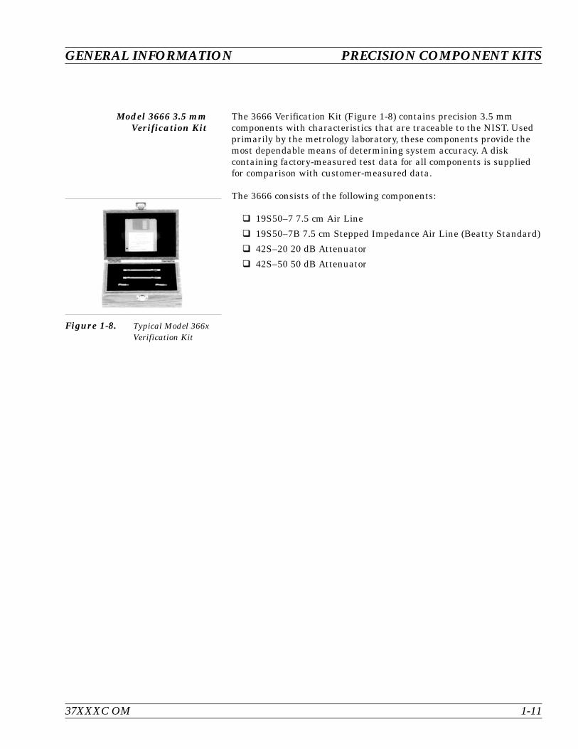
Model 3666 3.5 mmVerification Kit
The 3666 Verification Kit (Figure 1-8) contains precision 3.5 mmcomponents with characteristics that are traceable to the NIST. Usedprimarily by the metrology laboratory, these components provide themost dependable means of determining system accuracy. A diskcontaining factory-measured test data for all components is suppliedfor comparison with customer-measured data.
The 3666 consists of the following components:
19S50–7 7.5 cm Air Line
19S50–7B 7.5 cm Stepped Impedance Air Line (Beatty Standard)
42S–20 20 dB Attenuator
42S–50 50 dB Attenuator
37XXXC OM 1-11
GENERAL INFORMATION PRECISION COMPONENT KITS
Figure 1-8. Typical Model 366xVerification Kit

Model 3667 GPC–7Verification Kit
The 3667 Verification Kit (Figure 1-9) contains precision GPC–7components with characteristics that are traceable to the NIST. Usedprimarily by the metrology laboratory, these components provide themost dependable means of determining system accuracy. A diskcontaining factory-measured test data for each component is suppliedfor comparison with customer-measured data.
The kit consists of the following components:
18A50–10B 10 cm Stepped Impedance Air Line(Beatty Standard)
18A50–10 10 cm Air Line
42A–20 20 dB Attenuator
42A–50 50 dB Attenuator
PRECISION COMPONENT KITS GENERAL INFORMATION
1-12 37XXXC OM
Figure 1-9. Typical Model 366xVerification Kit
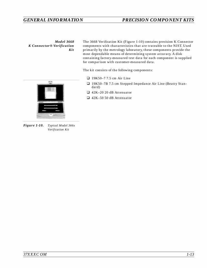
Model 3668K Connector® Verification
Kit
The 3668 Verification Kit (Figure 1-10) contains precision K Connectorcomponents with characteristics that are traceable to the NIST. Usedprimarily by the metrology laboratory, these components provide themost dependable means of determining system accuracy. A diskcontaining factory-measured test data for each component is suppliedfor comparison with customer-measured data.
The kit consists of the following components:
19K50–7 7.5 cm Air Line
19K50–7B 7.5 cm Stepped Impedance Air Line (Beatty Stan-dard)
42K–20 20 dB Attenuator
42K–50 50 dB Attenuator
37XXXC OM 1-13
GENERAL INFORMATION PRECISION COMPONENT KITS
Figure 1-10. Typical Model 366xVerification Kit
Model 3669/3669BV Connector® Verification
Kits
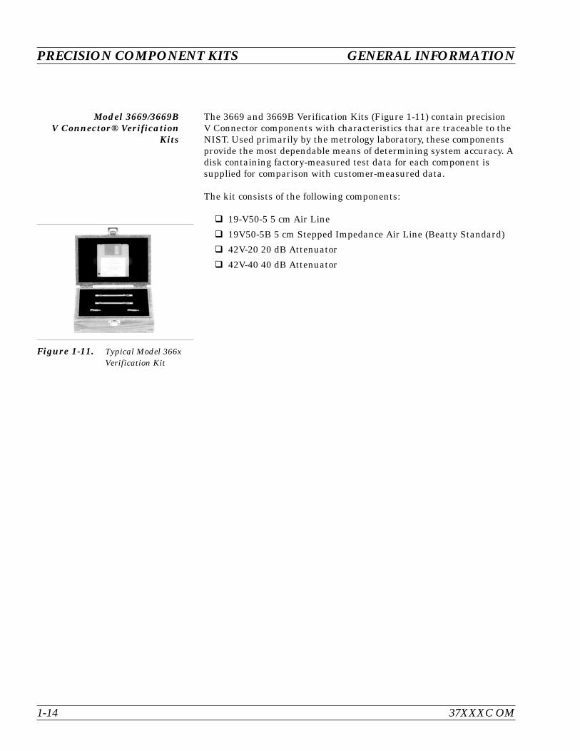
The 3669 and 3669B Verification Kits (Figure 1-11) contain precisionV Connector components with characteristics that are traceable to theNIST. Used primarily by the metrology laboratory, these componentsprovide the most dependable means of determining system accuracy. Adisk containing factory-measured test data for each component issupplied for comparison with customer-measured data.
The kit consists of the following components:
19-V50-5 5 cm Air Line
19V50-5B 5 cm Stepped Impedance Air Line (Beatty Standard)
42V-20 20 dB Attenuator
42V-40 40 dB Attenuator
PRECISION COMPONENT KITS GENERAL INFORMATION
1-14 37XXXC OM
Figure 1-11. Typical Model 366xVerification Kit
1-8 OPTIONS The following options are available:
Option 1: Rack Mount Kit
Option 2: Time (Distance) Domain Measurement Capability
Option 4: External SCSI Hard Drive Interface
Option 11: Reference Loop Extension Cables
Option 12: Rear Panel I.F. Inputs
Option 13: Delete source (371xxC models only)
1-9 PERFORMANCESPECIFICATIONS
System performance specifications are provided in Appendix C.
1-10 PREVENTIVEMAINTENANCE
The 37XXXC VNA system does not require any preventive mainte-nance.
37XXXC OM 1-15/1-16
GENERAL INFORMATION OPTIONS

Table of Contents
2-1 INTRODUCTION . . . . . . . . . . . . . . . . . . . . . . . . . . . . . . . . . . . 2-3
2-2 INITIAL INSPECTION . . . . . . . . . . . . . . . . . . . . . . . . . . . . . . . . 2-3
2-3 PREPARATION FOR USE . . . . . . . . . . . . . . . . . . . . . . . . . . . . . . 2-3
Option 4, External SCSI Drive Setup . . . . . . . . . . . . . . . . . . . . . . . 2-4
2-4 GPIB SETUP . . . . . . . . . . . . . . . . . . . . . . . . . . . . . . . . . . . . . 2-5
Interface Connector . . . . . . . . . . . . . . . . . . . . . . . . . . . . . . . . . 2-5
Cable Length Restrictions . . . . . . . . . . . . . . . . . . . . . . . . . . . . . 2-5
2-5 SYSTEM GPIB INTERCONNECTION. . . . . . . . . . . . . . . . . . . . . . . . 2-6
GPIB Interface to an External Plotter . . . . . . . . . . . . . . . . . . . . . . . 2-6
GPIB Addresses . . . . . . . . . . . . . . . . . . . . . . . . . . . . . . . . . . . 2-6
2-6 EXTERNAL MONITOR CONNECTOR . . . . . . . . . . . . . . . . . . . . . . . 2-6
2-7 RACK MOUNT. . . . . . . . . . . . . . . . . . . . . . . . . . . . . . . . . . . . . 2-6
2-8 STORAGE OR SHIPMENT . . . . . . . . . . . . . . . . . . . . . . . . . . . . . . 2-9
Preparation for Storage . . . . . . . . . . . . . . . . . . . . . . . . . . . . . . . 2-9
Preparation for Shipment. . . . . . . . . . . . . . . . . . . . . . . . . . . . . . 2-9
2-9 SERVICE CENTERS . . . . . . . . . . . . . . . . . . . . . . . . . . . . . . . . . 2-10
Chapter 2Installation

Chapter 2Installation
2-1 INTRODUCTION This chapter provides information for the initial inspection and prepa-ration for use of the 37XXXC Vector Network Analyzer. Informationfor interfacing the 37XXXC to the IEEE-488 General Purpose Inter-face Bus and reshipment and storage information is also included.
2-2 INITIAL INSPECTION Inspect the shipping container for damage. If the container or cushion-ing material is damaged, retain until the contents of the shipmenthave been checked against the packing list and the instrument hasbeen checked for mechanical and electrical operation.
If the 37XXXC is damaged mechanically, notify your local sales repre-sentative or Anritsu Customer Service. If either the shipping containeris damaged or the cushioning material shows signs of stress, notify thecarrier as well as Anritsu. Keep the shipping materials for the car-rier’s inspection.
2-3 PREPARATION FOR USE Except for units with Option 4 (see following page), no initial setup isrequired. After unpacking, the 37XXXC is ready for use. The 37XXXCis equipped with automatic line-power sensing, and will operate withany of the following line voltages: 100V, 120V, 220V, 240V +5%, –10%,48–63 Hz, 350 VA. The 37XXXC is intended for Installation Category(Overvoltage Category) II.
37XXXC OM 2-3
Use two or more people to lift and move this equipment, or use anequipment cart. There is a risk of back injury, if this equipment is liftedby one person.
WARNING
When supplying power to this equipment, always use a three-wirepower cable connected to a three-wire power line outlet. If power is sup-plied without grounding the equipment, there is a risk of receiving a se-vere or fatal electric shock.
WARNING
Option 4,External SCSI Drive Setup
The 37XXXC is available with an external SCSI drive interface as Op-tion 4. This option deletes the usual internal hard disk and providessupport for the use of an external SCSI drive.
An external SCSI drive and interface cable are not included withOption 4, but may be purchased from Anritsu. Contact your local salesrepresentative for information on availability and price. Compatibledrives may also be purchased from your local computer retailer.
Requirements:
Interface: SCSI, SCSI-2 Supported Drives: Iomega® Zip® 100MB SCSI, Zip® 250MB SCSI,
Jaz 1, Jaz 2 (other drives may operate, but are not guaranteed) Connector: Centronics 50 Male Pro Series SCSI I
(37XXXC is Female) SCSI ID: 5 Terminated: Yes
System Boot:Depending on your system configuration at the time of shipment, adrive (and cartridge) may be included. If not, your external drive mustbe connected to the 37XXXC and initialized with the system files asdescribed below before proceeding.
Ensure that the drive is configured correctly and powered on. If thedrive is a cartridge type, ensure that a cartridge with the system fileon it is installed. Turn on the 37XXXC and the system should boot nor-mally. Cartridges may then be exchanged if you wish to share files.
Initializing the Drive:A set of 37000 Basic Measurement Software floppy disks, Anritsu partnumber 2300-212, is required. This 4-disk set is supplied with yourshipment. Anritsu recommends BMS version 4.01 or above when usingan external SCSI drive.
NOTEThis operation will erase all of the files on the SCSI drive.Copy any important files before proceeding.
Step 1. Connect the external drive to the 37XXXC’s rear panel SCSI port withthe interface cable (refer to Appendix B for information on the rearpanel connectors). Ensure that the external SCSI drive is powered onwith a cartridge installed (if applicable).
Step 2. With the 37XXXC powered off, insert Disk 1 of the 37000 BMS into the37XXXC floppy drive.
Step 3. Power up the 37XXXC and immediately press any key to view the“Format Hard Drive” menu.
2-4 37XXXC OM
PREPARATION FOR USE INSTALLATION

Step 4. Press 1 to format the drive. Disk 1 will load automatically.
Step 5. Follow the instructions on the 37XXXC display to load the next threedisks. During this step, the system files are transferred to the SCSIdrive.
The SCSI drive initialization is now complete. The 37XXXC shouldsweep with no displayed errors and is now ready to boot-up from theexternal drive at power-on.
2-4 GPIB SETUP All functions of the 37XXXC (except power on/off and initialization ofthe hard disk) can be controlled remotely by an external computer/con-troller via the IEEE-488.2 GPIB. The information in this section per-tains to interface connections and cable requirements for the rearpanel GPIB connector. Refer to the Model 37XXXC Programming Man-ual, Anritsu Part Number 10410-00227, for information about remoteoperation of the 37XXXC using the GPIB.
The 37XXXC GPIB operates with any IBM XT, AT, or PS/2 compatiblecomputer/controller equipped with a National InstrumentsGPIB-PCII/IIA interface card and software.
Interface Connector Interface between the 37XXXC and other devices on the GPIB is via astandard 24-wire GPIB interface cable. For proper operation, orderAnritsu part number 2100-1, -2, -4, or -5 (1, 2, 4, or 0.5 meter length)cables through your local sales representative. This cable uses a dou-ble-sided connector; one connector face is a plug, the other a receptacle.These double-function connectors allow parallel connection of two ormore cables to a single instrument connector. The pin assignments forthe rear panel GPIB connector are shown in Figure B-1, located in Ap-pendix B.
Cable Length Restrictions The GPIB system can accommodate up to 15 instruments at any onetime. To achieve design performance on the bus, proper timing andvoltage level relationships must be maintained. If either the cablelength between separate instruments or the accumulated cable lengthbetween all instruments is too long, the data and control lines cannotbe driven properly and the system may fail to perform. Cable lengthrestrictions are as follows:
No more than 15 instruments may be installed on the bus.
Total accumulative cable length in meters may not exceed twotimes the number of bus instruments or 20 meters—whichever isless.
NOTEFor low EMI applications, the GPIB cable should be a fullyshielded type, with well-grounded metal-shell connec-tors. (Use Anritsu 2100-series cables.)
37XXXC OM 2-5
INSTALLATION GPIB SETUP

2-5 SYSTEM GPIBINTERCONNECTION
There are two rear panel GPIB IEEE-488 connectors. The IEEE 488.2connector used to interface the 37XXXC to an external computer/ con-troller via a standard GPIB cable. The Dedicated GPIB connector isused to interface to plotters and a second source for multiple sourceoperation via a standard GPIB cable.
GPIB Interface to anExternal Plotter
The 37XXXC GPIB interface can be configured to control a suitable ex-ternal plotter (refer to Chapter 6, Data Displays). In this mode of oper-ation, the GPIB is dedicated to this application and only the 37XXXCand the plotter are connected to the GPIB. Standard GPIB cables areused to interconnect to the plotter.
GPIB Addresses The 37XXXC leaves the factory with the default GPIB address set tosix. This address may be changed using the GP7 menu (see AppendixA).
2-6 EXTERNAL MONITORCONNECTOR
The rear panel External Monitor connector allows the internal displayinformation of the 37XXXC to be connected to an external VGA moni-tor (either color or monochrome). The pinout of this 15-pin Type D con-nector is shown in Figure B-4, located in Appendix B.
2-7 RACK MOUNT To install the Option 1 Rack Mount rails, refer to the below-listed pro-cedure.
Step 1. Disconnect the line cord and any other attachments from the instru-ment.
Step 2. Carefully place the instrument on its top (bottom-side up) on a secureand stable work surface.
SYSTEM GPIB INTERCONNECTION INSTALLATION
2-6 37XXXC OM

Step 3. Using a Phillips screwdriver, remove the two handles or four bumperassemblies (and tilt bail, if installed) from the front of the unit, andthe four feet at the rear (Figure 2-1). Save the screws for later use.
NOTES
The green-headed screws are metric threads and must be usedonly in the appropriately tapped holes
The feet, handles, and bumpers are not reused in this application
Step 4. Remove the center screws from the rear of the left and right side cov-ers.
Step 5. Remove the two side carrying handle screws (if so equipped) locatedunder the plastic handle ends.
Step 6. Remove the left and right side covers. These side covers are not reusedin this application.
Step 7. Install the two Rack Mount Handles using the green-headed screwsremoved earlier.
Refer to Figure 2-2, on the following page, for the remainder of theassembly procedure.
37XXXC OM 2-7
INSTALLATION RACK MOUNT
Figure 2-1. Removing Cover
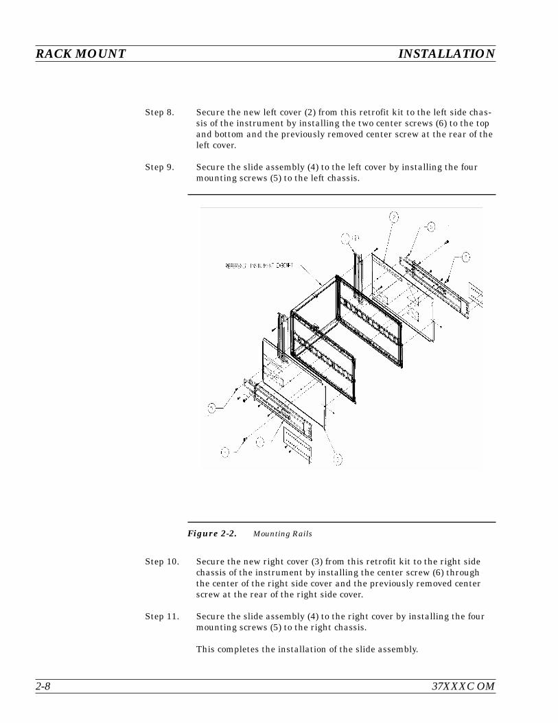
Step 8. Secure the new left cover (2) from this retrofit kit to the left side chas-sis of the instrument by installing the two center screws (6) to the topand bottom and the previously removed center screw at the rear of theleft cover.
Step 9. Secure the slide assembly (4) to the left cover by installing the fourmounting screws (5) to the left chassis.
Step 10. Secure the new right cover (3) from this retrofit kit to the right sidechassis of the instrument by installing the center screw (6) throughthe center of the right side cover and the previously removed centerscrew at the rear of the right side cover.
Step 11. Secure the slide assembly (4) to the right cover by installing the fourmounting screws (5) to the right chassis.
This completes the installation of the slide assembly.
RACK MOUNT INSTALLATION
2-8 37XXXC OM
Figure 2-2. Mounting Rails

2-8 STORAGE OR SHIPMENT The following paragraphs describe the procedure for preparing the37XXXC for storage or shipment.
Preparation for Storage Preparing the 37XXXC for storage consists of cleaning the unit, pack-ing the inside with moisture-absorbing desiccant crystals, and storingthe unit in a temperature environment that is maintained between–40 and +70 degrees centigrade (–40 to 156 degrees Fahrenheit).
Preparation for Shipment To provide maximum protection against damage in transit, the37XXXC should be repackaged in the original shipping container. Ifthis container is no longer available and the 37XXXC is being returnedto Anritsu for repair, advise Anritsu Customer Service; they will senda new shipping container free of charge. In the event neither of thesetwo options is possible, instructions for packaging and shipment aregiven below.
Use a Suitable ContainerObtain a corrugated cardboard carton with a 275-pound test strength.This carton should have inside dimensions of no less than six incheslarger than the instrument dimensions to allow for cushioning.
Protect the InstrumentSurround the instrument with polyethylene sheeting to protect the fin-ish.
Cushion the InstrumentCushion the instrument on all sides by tightly packing dunnage orurethane foam between the carton and the instrument. Provide atleast three inches of dunnage on all sides.
Seal the ContainerSeal the carton by using either shipping tape or an industrial stapler.
Address the ContainerIf the instrument is being returned to Anritsu for service, mark theAnritsu address and your return address on the carton in one or moreprominent locations. Refer to the address of your local representativelisted in Table 2-1 on the following page.
INSTALLATION STORAGE OR SHIPMENT
37XXXC OM 2-9/2-10
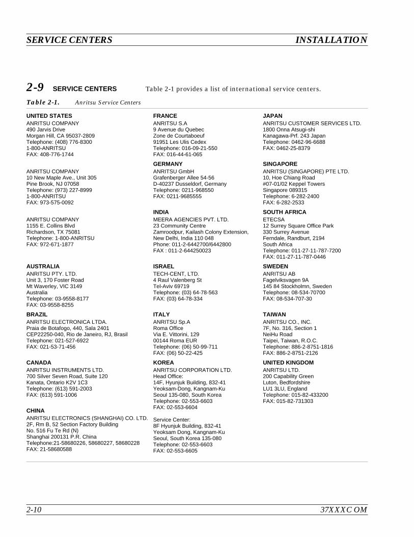
2-9 SERVICE CENTERS Table 2-1 provides a list of international service centers.
SERVICE CENTERS INSTALLATION
2-10 37XXXC OM
UNITED STATESANRITSU COMPANY490 Jarvis DriveMorgan Hill, CA 95037-2809Telephone: (408) 776-83001-800-ANRITSUFAX: 408-776-1744
FRANCEANRITSU S.A9 Avenue du QuebecZone de Courtaboeuf91951 Les Ulis CedexTelephone: 016-09-21-550FAX: 016-44-61-065
JAPANANRITSU CUSTOMER SERVICES LTD.1800 Onna Atsugi-shiKanagawa-Prf. 243 JapanTelephone: 0462-96-6688FAX: 0462-25-8379
ANRITSU COMPANY10 New Maple Ave., Unit 305Pine Brook, NJ 07058Telephone: (973) 227-89991-800-ANRITSUFAX: 973-575-0092
GERMANYANRITSU GmbHGrafenberger Allee 54-56D-40237 Dusseldorf, GermanyTelephone: 0211-968550FAX: 0211-9685555
SINGAPOREANRITSU (SINGAPORE) PTE LTD.10, Hoe Chiang Road#07-01/02 Keppel TowersSingapore 089315Telephone: 6-282-2400FAX: 6-282-2533
ANRITSU COMPANY1155 E. Collins BlvdRichardson, TX 75081Telephone: 1-800-ANRITSUFAX: 972-671-1877
INDIAMEERA AGENCIES PVT. LTD.23 Community CentreZamroodpur, Kailash Colony Extension,New Delhi, India 110 048Phone: 011-2-6442700/6442800FAX : 011-2-644250023
SOUTH AFRICAETECSA12 Surrey Square Office Park330 Surrey AvenueFerndale, Randburt, 2194South AfricaTelephone: 011-27-11-787-7200FAX: 011-27-11-787-0446
AUSTRALIAANRITSU PTY. LTD.Unit 3, 170 Foster RoadMt Waverley, VIC 3149AustraliaTelephone: 03-9558-8177FAX: 03-9558-8255
ISRAELTECH-CENT, LTD.4 Raul Valenberg StTel-Aviv 69719Telephone: (03) 64-78-563FAX: (03) 64-78-334
SWEDENANRITSU ABFagelviksvagen 9A145 84 Stockholmn, SwedenTelephone: 08-534-70700FAX: 08-534-707-30
BRAZILANRITSU ELECTRONICA LTDA.Praia de Botafogo, 440, Sala 2401CEP22250-040, Rio de Janeiro, RJ, BrasilTelephone: 021-527-6922FAX: 021-53-71-456
ITALYANRITSU Sp.ARoma OfficeVia E. Vittorini, 12900144 Roma EURTelephone: (06) 50-99-711FAX: (06) 50-22-425
TAIWANANRITSU CO., INC.7F, No. 316, Section 1NeiHu RoadTaipei, Taiwan, R.O.C.Telephone: 886-2-8751-1816FAX: 886-2-8751-2126
CANADAANRITSU INSTRUMENTS LTD.700 Silver Seven Road, Suite 120Kanata, Ontario K2V 1C3Telephone: (613) 591-2003FAX: (613) 591-1006
KOREAANRITSU CORPORATION LTD.Head Office:14F, Hyunjuk Building, 832-41Yeoksam-Dong, Kangnam-KuSeoul 135-080, South KoreaTelephone: 02-553-6603FAX: 02-553-6604
Service Center:8F Hyunjuk Building, 832-41Yeoksam Dong, Kangnam-KuSeoul, South Korea 135-080Telephone: 02-553-6603FAX: 02-553-6605
UNITED KINGDOMANRITSU LTD.200 Capability GreenLuton, BedfordshireLU1 3LU, EnglandTelephone: 015-82-433200FAX: 015-82-731303
CHINAANRITSU ELECTRONICS (SHANGHAI) CO. LTD.2F, Rm B, 52 Section Factory BuildingNo. 516 Fu Te Rd (N)Shanghai 200131 P.R. ChinaTelephone:21-58680226, 58680227, 58680228FAX: 21-58680588
Table 2-1. Anritsu Service Centers
Table of Contents
3-1 INTRODUCTION . . . . . . . . . . . . . . . . . . . . . . . . . . . . . . . . . . . 3-3
3-2 GENERAL DESCRIPTION . . . . . . . . . . . . . . . . . . . . . . . . . . . . . . 3-3
Source Module. . . . . . . . . . . . . . . . . . . . . . . . . . . . . . . . . . . . 3-4
Test Set Module . . . . . . . . . . . . . . . . . . . . . . . . . . . . . . . . . . . 3-4
Analyzer Module . . . . . . . . . . . . . . . . . . . . . . . . . . . . . . . . . . 3-4
3-3 NETWORK ANALYZERS . . . . . . . . . . . . . . . . . . . . . . . . . . . . . . . 3-5
Chapter 3Network Analyzers,A Primer

Chapter 3Network Analyzers,A Primer
3-1 INTRODUCTION This section provides front panel operating and measurement applica-tion information and data. It includes discussions on the following top-ics:
System description
General discussion about network analyzers
Basic measurements and how to make them
Error correction
General discussion on test sets
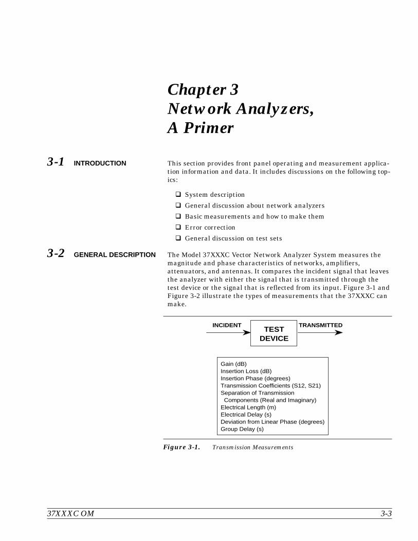
3-2 GENERAL DESCRIPTION The Model 37XXXC Vector Network Analyzer System measures themagnitude and phase characteristics of networks, amplifiers,attenuators, and antennas. It compares the incident signal that leavesthe analyzer with either the signal that is transmitted through thetest device or the signal that is reflected from its input. Figure 3-1 andFigure 3-2 illustrate the types of measurements that the 37XXXC canmake.
37XXXC OM 3-3
TRANSMITTEDINCIDENTTEST
DEVICE
Gain (dB)Insertion Loss (dB)Insertion Phase (degrees)Transmission Coefficients (S12, S21)Separation of Transmission Components (Real and Imaginary)Electrical Length (m)Electrical Delay (s)Deviation from Linear Phase (degrees)Group Delay (s)
Figure 3-1. Transmission Measurements
The 37XXXC is a self-contained, fully integrated measurement systemthat includes an optional time domain capability. The system hard-ware consists of the following:
Analyzer
Precision components required for calibration and performanceverification
Optional use of Anritsu 67XXB, 68XXXA/B/C, or 69XXXA/B as asecond source
The 37XXXC internal system modules perform the following functions:
Source Module This module provides the stimulus to the device under test (DUT). Thefrequency range of the source and test set modules establish the fre-quency range of the system. The frequency stability of the source is animportant factor in the accuracy (especially phase accuracy) of the net-work analyzer. Hence, the 37XXXC always phase locks the source to aninternal 10 MHz crystal reference.
Test Set Module The test set module routes the stimulus signal to the DUT and sam-ples the reflected and transmitted signals. The type of connector usedis important, as is the “Auto Reversing” feature. Auto Reversing meansthat it applies the stimulus signal in both the forward and reverse di-rection. The direction is reversed automatically. This saves you fromhaving to reverse the test device physically to measure all four scatter-ing parameters (S-parameters). Frequency conversion (1st and 2ndIFs) occurs in the test set module.
Analyzer Module The analyzer module down-converts, receives, and interprets the 3rdIF signal for phase and magnitude data. It then displays the results ofthis analysis on a large, 190 mm (7-1/2 inch) diagonal color display.This display can show all four S-parameters simultaneously. In addi-tion to the installed display, you can also view the measurement re-sults on an external color monitor.
GENERAL DESCRIPTION NETWORK ANALYZERS, A PRIMER
3-4 37XXXC OM
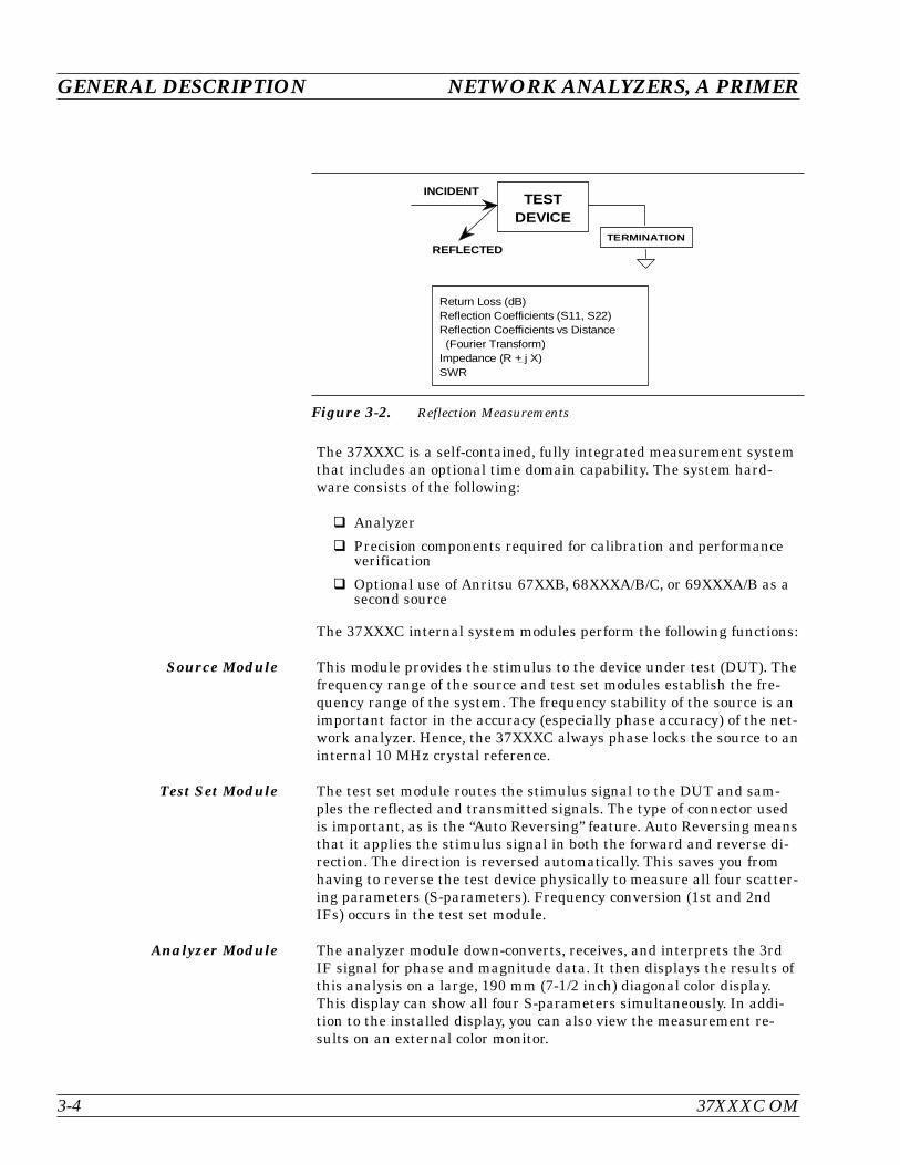
REFLECTED
INCIDENT
TERMINATION
TESTDEVICE
Return Loss (dB)Reflection Coefficients (S11, S22)Reflection Coefficients vs Distance (Fourier Transform)Impedance (R + j X)SWR
Figure 3-2. Reflection Measurements
3-3 NETWORK ANALYZERS We will begin this discussion with a subject familiar to most Anritsucustomers: scalar network analysis. After showing comparisons, wewill proceed to the fundamentals of network analyzer terminology andtechniques. This discussion serves as an introduction to topics pre-sented in greater detail later in this section. This discussion will touchon new concepts that include the following:
Reference Delay
S-parameters: what they are and how they are displayed
Complex Impedance and Smith Charts
Scalar Analyzer ComparisonNetwork Analyzers do everything that scalar analyzers do except dis-play absolute power. In addition, they add the ability to measure thephase characteristics of microwave devices and allow greater dynamicrange.
If all a Network Analyzer added was the capability for measuringphase characteristics, its usefulness would be limited. While phasemeasurements are important in themselves, it is the availability ofthis phase information that unlocks many new features for complexmeasurements. These features include Smith Charts, Time Domain,and Group Delay. Phase information also allows greater accuracythrough vector error correction of the measured signal.
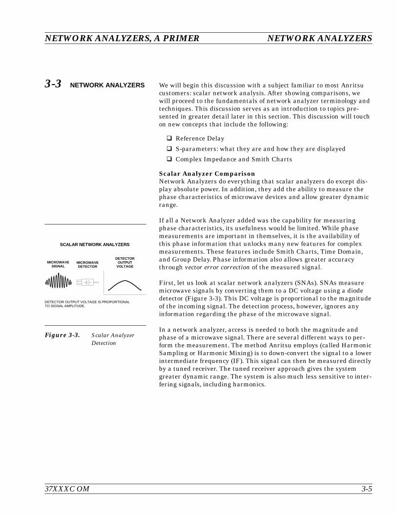
First, let us look at scalar network analyzers (SNAs). SNAs measuremicrowave signals by converting them to a DC voltage using a diodedetector (Figure 3-3). This DC voltage is proportional to the magnitudeof the incoming signal. The detection process, however, ignores anyinformation regarding the phase of the microwave signal.
In a network analyzer, access is needed to both the magnitude andphase of a microwave signal. There are several different ways to per-form the measurement. The method Anritsu employs (called HarmonicSampling or Harmonic Mixing) is to down-convert the signal to a lowerintermediate frequency (IF). This signal can then be measured directlyby a tuned receiver. The tuned receiver approach gives the systemgreater dynamic range. The system is also much less sensitive to inter-fering signals, including harmonics.
37XXXC OM 3-5
NETWORK ANALYZERS, A PRIMER NETWORK ANALYZERS
SCALAR NETWORK ANALYZERS
MICROWAVESIGNAL
MICROWAVEDETECTOR
DETECTOROUTPUT
VOLTAGE
DETECTOR OUTPUT VOLTAGE IS PROPORTIONALTO SIGNAL AMPLITUDE.
Figure 3-3. Scalar AnalyzerDetection

Vector Network Analyzer BasicsThe network analyzer is a tuned receiver (Figure 3-4, left). Themicrowave signal is down converted into the passband of the IF. Tomeasure the phase of this signal, we must have a reference to compareit with. If the phase of a signal is 90 degrees, it is 90 degrees differentfrom the reference signal (Figure 3-5, left). The network analyzerwould read this as –90 degrees, since the test signal is delayed by 90degrees with respect to the reference signal.
This phase reference can be obtained by splitting off some of themicrowave signal before the measurement (Figure 3-7, below).
The phase of the microwave signal after it has passed through the de-vice under test (DUT) is then compared with the reference signal. Anetwork analyzer test set automatically samples the reference signal,so no external hardware is needed.
Let us consider for a moment that you remove the DUT and substitutea length of transmission line (Figure 3-6, left). Note that the pathlength of the test signal is longer than that of the reference signal.Now let us see how this affects our measurement.
NETWORK ANALYZERS NETWORK ANALYZERS, A PRIMER
3-6 37XXXC OM
Figure 3-4. Network Analyzer isa Tuned Receiver
PHASE MEASUREMENT
TIME
TESTSIGNAL
REFERENCESIGNAL
90
Figure 3-5. Signals with a90 Degree PhaseDifference
REFERENCESIGNAL
SPLITTER
TESTSIGNAL
MICROWAVESOURCE
LONGERPATH
LENGTH
PHASEDETECTOR
Figure 3-6. Split Signal wherea Length of LineReplaces the DUT
A NETWORK ANALYZER IS A TUNED RECEIVER
TUNABLELOCALOSCILLATOR
INTERMEDIATEFREQUENCY (IF)
MICROWAVESIGNAL
• GREATER DYNAMIC RANGE• LESS SENSIVITY TO INTERFERING SIGNALS
DUT
PHASEDETECTOR
REFERENCESIGNAL
SPLITTER
TESTSIGNAL
MICROWAVESOURCE
Figure 3-7. Splitting the Microwave Signal
Assume that we are making a measurement at 1 GHz and that thedifference in path-length between the two signals is exactly 1wavelength. This means that test signal is lagging the reference signalby 360 degrees (Figure 3-8). We cannot really tell the differencebetween one sine wave maxima and the next (they are all identical), sothe network analyzer would measure a phase difference of 0 degrees.
Now consider that we make this same measurement at 1.1 GHz. Thefrequency is higher by 10 percent so therefore the wavelength isshorter by 10 percent. The test signal path length is now 0.1wavelength longer than that of the reference signal (Figure 3-9). Thistest signal is:
1.1 X 360 = 396 degrees
This is 36 degrees different from the phase measurement at 1 GHz.The network analyzer will display this phase difference as –36 de-grees.
The test signal at 1.1 GHz is delayed by 36 degrees more than the testsignal at 1 GHz.
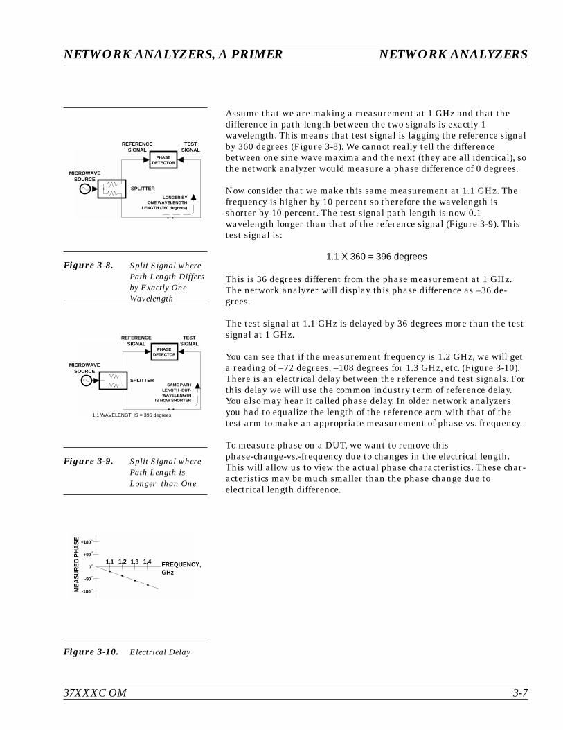
You can see that if the measurement frequency is 1.2 GHz, we will geta reading of –72 degrees, –108 degrees for 1.3 GHz, etc. (Figure 3-10).There is an electrical delay between the reference and test signals. Forthis delay we will use the common industry term of reference delay.You also may hear it called phase delay. In older network analyzersyou had to equalize the length of the reference arm with that of thetest arm to make an appropriate measurement of phase vs. frequency.
To measure phase on a DUT, we want to remove thisphase-change-vs.-frequency due to changes in the electrical length.This will allow us to view the actual phase characteristics. These char-acteristics may be much smaller than the phase change due toelectrical length difference.
37XXXC OM 3-7
NETWORK ANALYZERS, A PRIMER NETWORK ANALYZERS
REFERENCESIGNAL
SPLITTER
TESTSIGNAL
MICROWAVESOURCE
PHASEDETECTOR
LONGER BYONE WAVELENGTH
LENGTH (360 degrees)
Figure 3-8. Split Signal wherePath Length Differsby Exactly OneWavelength
REFERENCESIGNAL
SPLITTER
TESTSIGNAL
MICROWAVESOURCE
SAME PATHLENGTH -BUT-WAVELENGTH
IS NOW SHORTER
1.1 WAVELENGTHS = 396 degrees
PHASEDETECTOR
Figure 3-9. Split Signal wherePath Length isLonger than One
+180
+90
0
-90
-180
1.1 1.2 1.3 1.4 FREQUENCY,GHz
ME
AS
UR
ED
PH
AS
E
Figure 3-10. Electrical Delay
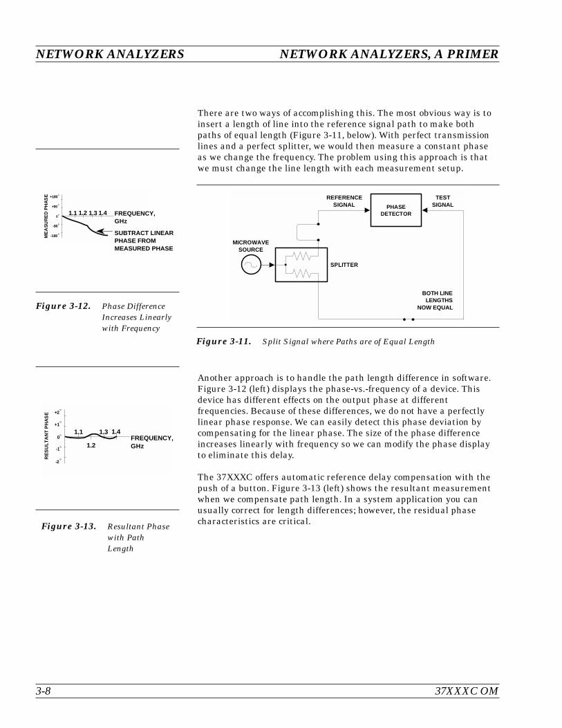
There are two ways of accomplishing this. The most obvious way is toinsert a length of line into the reference signal path to make bothpaths of equal length (Figure 3-11, below). With perfect transmissionlines and a perfect splitter, we would then measure a constant phaseas we change the frequency. The problem using this approach is thatwe must change the line length with each measurement setup.
Another approach is to handle the path length difference in software.Figure 3-12 (left) displays the phase-vs.-frequency of a device. Thisdevice has different effects on the output phase at differentfrequencies. Because of these differences, we do not have a perfectlylinear phase response. We can easily detect this phase deviation bycompensating for the linear phase. The size of the phase differenceincreases linearly with frequency so we can modify the phase displayto eliminate this delay.
The 37XXXC offers automatic reference delay compensation with thepush of a button. Figure 3-13 (left) shows the resultant measurementwhen we compensate path length. In a system application you canusually correct for length differences; however, the residual phasecharacteristics are critical.
NETWORK ANALYZERS NETWORK ANALYZERS, A PRIMER
3-8 37XXXC OM
PHASEDETECTOR
REFERENCESIGNAL
SPLITTER
TESTSIGNAL
MICROWAVESOURCE
BOTH LINELENGTHS
NOW EQUAL
Figure 3-11. Split Signal where Paths are of Equal Length
+180
+90
0
-90
-180
1.1 1.2 1.3 1.4 FREQUENCY,GHz
ME
AS
UR
ED
PH
AS
E
SUBTRACT LINEARPHASE FROMMEASURED PHASE
Figure 3-12. Phase DifferenceIncreases Linearlywith Frequency
01.1
1.2
1.3 1.4FREQUENCY,GHz
+2
+1
-1
-2
RE
SU
LTA
NT
PH
AS
E
Figure 3-13. Resultant Phasewith PathLength
Network Analyzer Measurements
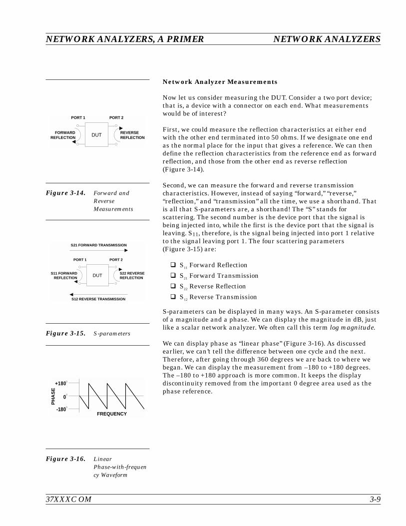
Now let us consider measuring the DUT. Consider a two port device;that is, a device with a connector on each end. What measurementswould be of interest?
First, we could measure the reflection characteristics at either endwith the other end terminated into 50 ohms. If we designate one endas the normal place for the input that gives a reference. We can thendefine the reflection characteristics from the reference end as forwardreflection, and those from the other end as reverse reflection(Figure 3-14).
Second, we can measure the forward and reverse transmissioncharacteristics. However, instead of saying “forward,” “reverse,”“reflection,” and “transmission” all the time, we use a shorthand. Thatis all that S-parameters are, a shorthand! The “S” stands forscattering. The second number is the device port that the signal isbeing injected into, while the first is the device port that the signal isleaving. S11, therefore, is the signal being injected into port 1 relativeto the signal leaving port 1. The four scattering parameters(Figure 3-15) are:
S11 Forward Reflection
S21 Forward Transmission
S22 Reverse Reflection
S12 Reverse Transmission
S-parameters can be displayed in many ways. An S-parameter consistsof a magnitude and a phase. We can display the magnitude in dB, justlike a scalar network analyzer. We often call this term log magnitude.
We can display phase as “linear phase” (Figure 3-16). As discussedearlier, we can’t tell the difference between one cycle and the next.Therefore, after going through 360 degrees we are back to where webegan. We can display the measurement from –180 to +180 degrees.The –180 to +180 approach is more common. It keeps the displaydiscontinuity removed from the important 0 degree area used as thephase reference.
37XXXC OM 3-9
NETWORK ANALYZERS, A PRIMER NETWORK ANALYZERS
FORWARDREFLECTION
REVERSEREFLECTION
PORT 1 PORT 2
DUT
Figure 3-14. Forward andReverseMeasurements
S12 REVERSE TRANSMISSION
PORT 1 PORT 2
S11 FORWARDREFLECTION
S22 REVERSEREFLECTION
S21 FORWARD TRANSMISSION
DUT
Figure 3-15. S-parameters
+180
0
-180
PH
AS
E
FREQUENCY
Figure 3-16. LinearPhase-with-frequency Waveform

There are several ways in which all the information can be displayedon one trace. One method is a polar display (Figure 3-17). The radialparameter (distance from the center) is magnitude. The rotationaround the circle is phase. We sometimes use polar displays to viewtransmission measurements, especially on cascaded devices (devices inseries). The transmission result is the addition of the phase and logmagnitude (dB) information of each device’s polar display.
As we have discussed, the signal reflected from a DUT has both mag-nitude and phase. This is because the impedance of the device hasboth a resistive and a reactive term of the form r+jx. We refer to the ras the real or resistive term, while we call x the imaginary or reactiveterm. The j, which we sometimes denote as i, is an imaginary number.It is the square root of –1. If x is positive, the impedance is inductive; ifx is negative, the impedance is capacitive.
The size and polarity of the reactive component x is important in im-pedance matching. The best match to a complex impedance is the com-plex conjugate. This complex-sounding term simply means an imped-ance with the same value of r and x, but with x of opposite polarity.This term is best analyzed using a Smith Chart (Figure 3-18), which isa plot of r and x.
To display all the information on a single S-parameter requires one ortwo traces, depending upon the format we want. A very common re-quirement is to view forward reflection on a Smith Chart (one trace)while observing forward transmission in Log Magnitude and Phase(two traces). Let us see how to accomplish this in the 37XXXC.
The 37XXXC has four channels. Each channel can display a completeS-parameter in any format on either one or two traces. All four S-pa-rameters can be seen simultaneously in any desired format. A total ofeight traces can be viewed at the same time. While this is a lot of infor-mation to digest, the 37XXXC’s large color display makes recognizingand analyzing the data surprisingly easy.
NETWORK ANALYZERS NETWORK ANALYZERS, A PRIMER
3-10 37XXXC OM
-90
180
90
0
POLAR DISPLAY
Figure 3-17. Polar Display
50
INDUCTIVE
CAPACITIVE
SMITH CHART
Figure 3-18. Smith Chart
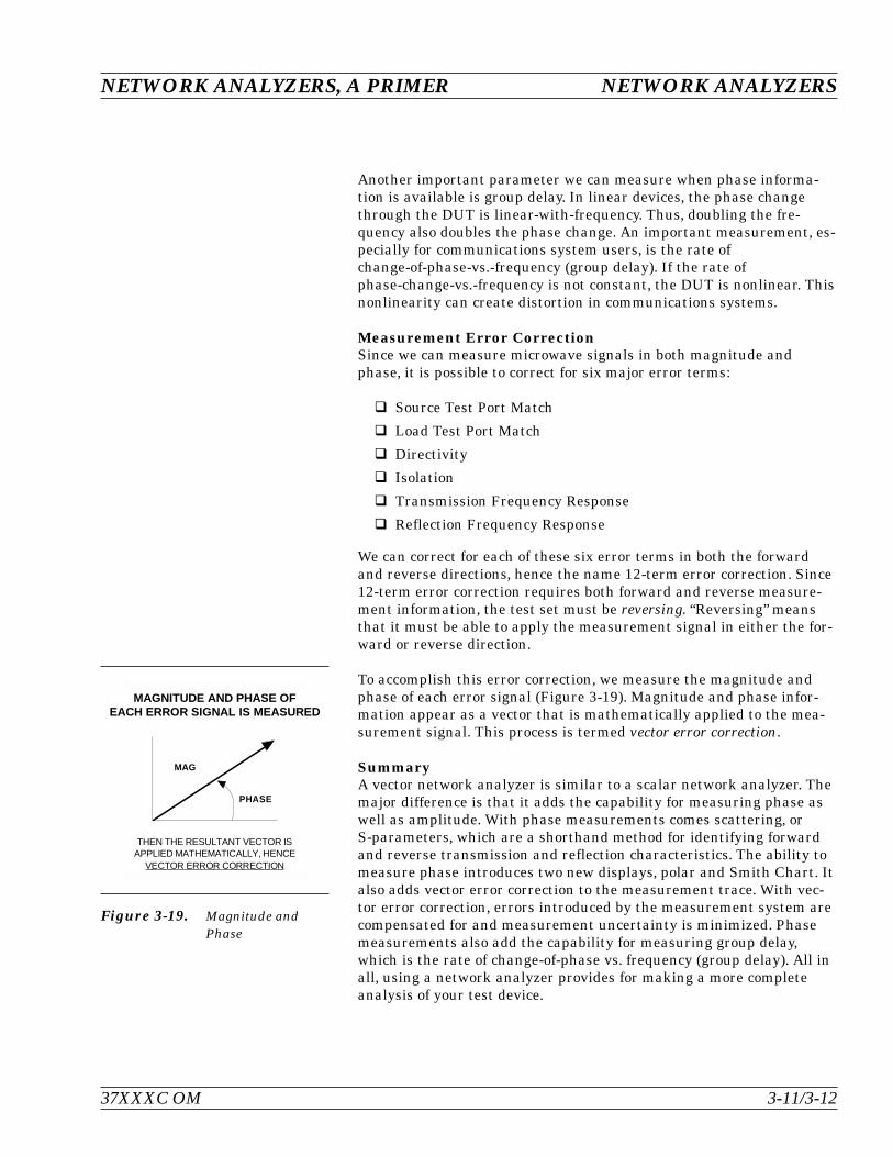
Another important parameter we can measure when phase informa-tion is available is group delay. In linear devices, the phase changethrough the DUT is linear-with-frequency. Thus, doubling the fre-quency also doubles the phase change. An important measurement, es-pecially for communications system users, is the rate ofchange-of-phase-vs.-frequency (group delay). If the rate ofphase-change-vs.-frequency is not constant, the DUT is nonlinear. Thisnonlinearity can create distortion in communications systems.
Measurement Error CorrectionSince we can measure microwave signals in both magnitude andphase, it is possible to correct for six major error terms:
Source Test Port Match
Load Test Port Match
Directivity
Isolation
Transmission Frequency Response
Reflection Frequency Response
We can correct for each of these six error terms in both the forwardand reverse directions, hence the name 12-term error correction. Since12-term error correction requires both forward and reverse measure-ment information, the test set must be reversing. “Reversing” meansthat it must be able to apply the measurement signal in either the for-ward or reverse direction.
To accomplish this error correction, we measure the magnitude andphase of each error signal (Figure 3-19). Magnitude and phase infor-mation appear as a vector that is mathematically applied to the mea-surement signal. This process is termed vector error correction.
SummaryA vector network analyzer is similar to a scalar network analyzer. Themajor difference is that it adds the capability for measuring phase aswell as amplitude. With phase measurements comes scattering, orS-parameters, which are a shorthand method for identifying forwardand reverse transmission and reflection characteristics. The ability tomeasure phase introduces two new displays, polar and Smith Chart. Italso adds vector error correction to the measurement trace. With vec-tor error correction, errors introduced by the measurement system arecompensated for and measurement uncertainty is minimized. Phasemeasurements also add the capability for measuring group delay,which is the rate of change-of-phase vs. frequency (group delay). All inall, using a network analyzer provides for making a more completeanalysis of your test device.
NETWORK ANALYZERS, A PRIMER NETWORK ANALYZERS
37XXXC OM 3-11/3-12
VECTOR ERROR CORRECTION
THEN THE RESULTANT VECTOR ISAPPLIED MATHEMATICALLY, HENCE
MAGNITUDE AND PHASE OFEACH ERROR SIGNAL IS MEASURED
MAG
PHASE
Figure 3-19. Magnitude andPhase


Table of Contents
4-1 INTRODUCTION . . . . . . . . . . . . . . . . . . . . . . . . . . . . . . . . . . . 4-3
4-2 KEY-GROUPS . . . . . . . . . . . . . . . . . . . . . . . . . . . . . . . . . . . . . 4-3
4-3 CALIBRATION KEY-GROUP . . . . . . . . . . . . . . . . . . . . . . . . . . . . 4-10
4-4 SAVE/RECALL MENU KEY . . . . . . . . . . . . . . . . . . . . . . . . . . . . . 4-21
4-5 MEASUREMENT KEY-GROUP . . . . . . . . . . . . . . . . . . . . . . . . . . 4-22
4-6 CHANNELS KEY-GROUP . . . . . . . . . . . . . . . . . . . . . . . . . . . . . . 4-25
4-7 DISPLAY KEY-GROUP . . . . . . . . . . . . . . . . . . . . . . . . . . . . . . . 4-26
4-8 ENHANCEMENT KEY-GROUP. . . . . . . . . . . . . . . . . . . . . . . . . . . 4-30
4-9 HARD COPY KEY-GROUP . . . . . . . . . . . . . . . . . . . . . . . . . . . . . 4-32
4-10 SYSTEM STATE KEY-GROUP . . . . . . . . . . . . . . . . . . . . . . . . . . . 4-34
4-11 MARKERS/LIMITS KEY-GROUP . . . . . . . . . . . . . . . . . . . . . . . . . . 4-37
4-12 DISK STORAGE INTERFACE . . . . . . . . . . . . . . . . . . . . . . . . . . . 4-41
Disk Format . . . . . . . . . . . . . . . . . . . . . . . . . . . . . . . . . . . . 4-41
Disk Files. . . . . . . . . . . . . . . . . . . . . . . . . . . . . . . . . . . . . . 4-41
Disk File Output Device . . . . . . . . . . . . . . . . . . . . . . . . . . . . . . 4-42
Formatting a Data File Disk . . . . . . . . . . . . . . . . . . . . . . . . . . . 4-42
Copying Data Files From Disk to Disk . . . . . . . . . . . . . . . . . . . . . . 4-42
Recovering From Disk Write/Read Errors . . . . . . . . . . . . . . . . . . . . 4-42
4-13 COMMAND LINE . . . . . . . . . . . . . . . . . . . . . . . . . . . . . . . . . . 4-43
Create Directory . . . . . . . . . . . . . . . . . . . . . . . . . . . . . . . . . . 4-43
List Directory . . . . . . . . . . . . . . . . . . . . . . . . . . . . . . . . . . . 4-43
Change Directory . . . . . . . . . . . . . . . . . . . . . . . . . . . . . . . . . 4-43
Delete Files . . . . . . . . . . . . . . . . . . . . . . . . . . . . . . . . . . . . 4-43
Remove Directory . . . . . . . . . . . . . . . . . . . . . . . . . . . . . . . . . 4-44
Copy Files . . . . . . . . . . . . . . . . . . . . . . . . . . . . . . . . . . . . . 4-44
Conventions . . . . . . . . . . . . . . . . . . . . . . . . . . . . . . . . . . . . 4-44
Chapter 4Front Panel Operation
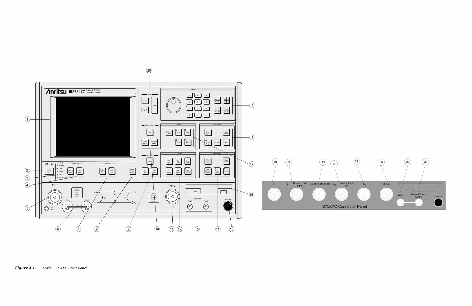
Calibration
Menu
Hard Copy
Markers/Limits
System State
Local Lockout
SRQ
Listen
Talk
Remote
GPIB
Power
Port 1
CAUTION
+30 dBm Max
40 VDC Max
Avoid Static
Discharge
9876
5
4
3
2
1
10
DefaultProgram
Utility
Menu
Begin
Cal
Apply
Cal
Save/
Recall
Menu
Start
Stop
Menu
Limits
MarkerMenu
ReadoutMarker
Graph
TypeSet
ScaleAutoScale
SParams
RefPlane
TraceMemory
Channel
MenuCh 1 Ch 2
Ch 3 Ch 4
Option
Menu
VideoIF BW
Avg/
SmoothMenu
TraceSmooth
Average
Setup
Menu
DataPoints
Hold Domain Appl
Enter
7 8 9
4 5 6
1 2 3
0. -
MHz
ns
X1
cm
GHz 103
us m
kHz
ps
10-3
mm
Clear
Ret Loc
Measurement
Enhancement
Channels
Data Entry
Display
a
a
S
b
12S
21S
S
b
11 22
1
1
2
2
CAUTION
+20 dBm Max
40 VDC Max
Avoid Static
Discharge
Port 2
11 12 14 15
16
18
17
19
20
37347CNetwork Analyzer
40MHz - 20GHz
Port 2Port 1
Bias Input
13
KeyboardInput Output
Figure 4-1. Model 37XXXC Front Panel
371XXC Connector Panel
22 23 2425 282721 26
Chapter 4Front Panel Operation
4-1 INTRODUCTION This chapter describes the front panel keys, controls, and menus. Thechapter is organized into an overall description of the front panelkey-groups and detailed descriptions of individual keys within thekey-groups.
4-2 KEY-GROUPS The following pages provide descriptions of the front panel key-groupsillustrated in Figure 4-1 on the previous page.
Index 1. LCD display: Displays any or all of the four mea-surement channels, plus menus.
Index 2. Power: Turns the 37XXXC on and off. When on, theoperating program runs a self test then recalls theparameters and functions in effect when previouslypowered down.
Index 3. GPIB Indicators:
Remote: Lights when the 37XXXC switches to re-mote (GPIB) control. It remains lit until the unit re-turns to local control.
Talk: Lights when you address the 37XXXC to talkand remains lit until unaddressed.
Listen: Lights when you address the 37XXXC to lis-ten and remains lit until unaddressed.
SRQ: Lights when the 37XXXC sends a Service Re-quests (SRQ) to the external controller. The LED re-mains lit until the 37XXXC receives a serial poll oruntil the controller resets the SRQ function.
Local Lockout: Lights when a local lockout mes-sage is received. The LED remains lit until the mes-sage is rescinded. When lit, you cannot return the37XXXC to local control via the front panel.
37XXXC OM 4-3

Index 4. System State Keys: (Refer to Section 4-10,page 4-34, for details and menu flow diagrams.)
Default Program: Resets the front panel to the fac-tory-preset state and displays Menu SU1 or SU3(Appendix A). Pressing this key in conjunction withthe “0” or “1” key resets certain internal memoriesand front panel key states (refer to Sections 4-5 and4-10).
NOTEUse of the Default Program key will destroyfront panel and calibration setup data, un-less they have been saved to disk.
Utility Menu: Displays the first in a series of menusthat let you perform diskette and other utility-typefunctions and operations.
Index 5. Port 1 Test Connector: Provides an input test con-nection for the device-under-test (DUT).
Index 6. Amplifier Loop: Provides for inserting additionalamplification before the coupler.
Index 7. Calibration Keys: (Refer to Section 4-3, page 4-11,for details and menu flow diagrams.)
Begin Cal: Calls up the first in a sequence ofmenus that guide you through a measurement cali-bration. Refer to Section 4-3 for a detailed discus-sion of the calibration keys, indicators, and menus.
Apply Cal: Turns on and off the applied error cor-rection and tune mode.
Index 8. Save/Recall Menu Key: Displays the first of severalmenus that let you save the current calibration orfront panel setup or recall a previously saved cali-bration or setup. Refer to Section 4-4, page 4-21, formenu flow diagram.
KEY-GROUPS FRONT PANEL OPERATION
4-4 37XXXC OM
Index 9. Hard Copy Keys: (Refer to Section 4-9, page 4-32,for details and menu flow diagrams.)
Menu: Displays option menus that let you definewhat will happen each time you press the StartPrint key. The displayed menu also selects disk I/Ooperations.
Start Print: Tells the printer or plotter to start out-put based on the current selections.
Stop Print: Immediately stops printing the data,clears the print buffer, and sends a form-feed com-mand to the printer.
Index 10. Markers/Limits Keys: (Refer to Section 4-11,page 4-37, for details and menu flow diagrams.)
Marker Menu: Displays the first in a series ofmenus that let you set and manipulate marker fre-quencies, times, and distances.
Readout Marker: Displays a menu that lists all ofthe active markers. If no markers are active, themarker menu is displayed.
Limits: Displays one of the menus that let you ma-nipulate the limit lines.
Index 11. Port 2 Test Connector: Provides an input test con-nection for the device-under-test (DUT).
37XXXC OM 4-5
FRONT PANEL OPERATION KEY-GROUPS

Index 12. Display Keys: (Refer to Section 4-7, page 4-26, fordetails and menu flow diagrams.)
Graph Type: Displays the two menus that let youchoose the graph type for the active channel.
Set Scale: Displays the appropriate scaling menu,based on the graph type for the active channel.
Auto Scale: Automatically scales the active chan-nel for optimum viewing.
S Params: Displays Menu SP (Appendix A), whichlets you choose between S11, S12, S21, or S22. Youmay display the same parameter on two or morechannels.
Ref Plane: Displays the first of two menus that letyou set the reference plane for the active channel intime or distance. For a correct distance readout, youmust set the dielectric constant to the correct value.Refer to the discussion in menu RD2 (Appendix A).
Trace Memory: Displays the menus that let you doany of the following. (1) Store the measured data inmemory. (2) View the stored data. (3) Add, subtract,multiply, or divide the measured data from thestored data (normalize to the stored memory). (4)View both the measured and the stored data simul-taneously on the active channel. (5) Store/Recallsaved data to disk. Four memories exist—one foreach channel. This lets you normalize the data ineach channel independently. The LED on this but-ton lights when the active channel is displayingmemory data or measurement data normalized tomemory.
Index 13. Bias Input connectors:
Port 1: Provides for supplying a bias voltage for thePort 1 input.
Port 2: Provides for supplying a bias voltage for thePort 2 input.
KEY-GROUPS FRONT PANEL OPERATION
4-6 37XXXC OM

Index 14. Enhancement Keys: (Refer to Section 4-8,page 4-30 for details and menu flow diagrams.)
Option Menu: Displays a series of menus showingthe choice of optional features.
Video IF BW: Displays a menu that lets you chosebetween 10 kHz, 1 kHz, 100 Hz, or 10 Hz intermedi-ate frequency (IF) bandwidth filters.
Avg/Smooth Menu: Displays a menu that lets youenter values for Averaging and Smoothing.
Trace Smooth: Turns the trace smoothing functionon and off.
Average: Turns the average function on and off.
Index 15. Keyboard connector: Provides for connecting anexternal IBM-AT-type keyboard. All alphanumericfield entries can be input from this keyboard. Theseinputs include Device ID, Model, Date, OperatorIdentification, frequencies, filenames, as well ascomment-type entries. The analog knob and keypadinput for these entries remains active. The F1through F12 function keys can be used to access cer-tain key and menu functions. A template is pro-vided. Two versions of an actual-size template areprovided in a foldout page at the end of this chapterin the event a replacement is needed.
Index 16. Diskette Drive: Provides a drive for the 3.5-inch,high-density (1.44 MB) floppy diskette used to storeselected front panel setups and calibrations. Refer toSection 4-12, page 4-41, for disk storage informa-tion.
37XXXC OM 4-7
FRONT PANEL OPERATION KEY-GROUPS

Index 17. Channels Keys: (Refer to Section 4-6, page 4-25, fordetails and menu flow diagrams.)
Channel Menu: Displays a menu that lets you se-lect the format for the number of channels dis-played.
Ch 1: Makes Channel 1 the active channel. The ac-tive channel is the one acted on by the keys in theDisplay section. Only one channel can be active atany one time.
Ch 2: Makes Channel 2 the active channel.
Ch 3: Makes Channel 3 the active channel.
Ch 4: Makes Channel 4 the active channel.
Index 18. Measurement Keys: (Refer to Section 4-5,page 4-22 for details and menu flow diagrams.)
Setup Menu: Displays the first of several menusthat let you select functions affecting measure-ments.
Data Points: Displays a menu that lets you selectbetween 1601, 801, 401, 201, 101, or 51 data points.
Hold: Toggles the instrument in and out of the holdmode; or it triggers a sweep, depending on the func-tion selected in menu SU4 (Appendix A).
Domain: Displays the first in a series of menus thatlet you set the Time Domain display parameters.(This key is only active if your 37XXXC is equippedwith the Time Domain option.)
If already in the Domain menus, pressing thiskey will return to the first menu in the sequence.
If in the Domain menus and another (non-timedomain) menu is displayed by pushing a menukey, the last displayed domain menu redisplayswhen the Domain key is next pressed.
Applications Menu: Displays the first in a series ofmenus that provide instructions for adapter removaland gain compression.
KEY-GROUPS FRONT PANEL OPERATION
4-8 37XXXC OM
Index 19. Data Entry Keys:
Rotary Knob: Used to alter measurement valuesfor the active parameter (Start Frequency, Stop Fre-quency, Offset, etc.).
Keypad: Provides for entering values for the activeparameter. The active parameter is the one to whichthe menu cursor is pointing.
MHz/X1/ns/cm: Terminates a value entered on thekeypad in the units shown—that is; megahertz forfrequency, unity for dimensionless or angle entries,nanoseconds for time, or centimeters for length.
GHz/103/ms/m: Terminates a value entered on thekeypad in the units shown—that is; gigahertz forfrequency, 1103 power for dimensionless or angleentries, microseconds for time, or meters for length.
kHz/10-3/ps/mm: Terminates a value entered on thekeypad in the units shown—that is; kilohertz forfrequency, 110-3 for dimensionless or angle entries,picoseconds for time, or millimeters for length.
a. Clear/Ret Loc: Local (Non-GPIB) Mode: (1)The key clears entries not yet terminated byone of the terminator keys above, which allowsthe previously displayed values to redisplay. Or(2) the key turns off the displayed menu andexpands the data area to fill the entire screen,if you have not made any keypad entries need-ing termination.
b. GBIB Mode: The key returns the instrument tolocal (front panel) control, unless the controllerhas sent a local lockout message (LLO) overthe bus.
Index 20. Menu Keys:
Arrow Keys: Moves the menu cursor up and downto select items appearing in the menu area of theLCD.
Enter: Implements the menu selection chosen usingthe arrow keys.
37XXXC OM 4-9
FRONT PANEL OPERATION KEY-GROUPS

Index 21. b1 Test Connector: Provides an input test connec-tion to the b1 sampler.
Index 22. a1/Source Lock Input Connector: Provides an in-put test connection to the a1 sampler.
Index 23. Source Lock Output Connector: Provides an RFoutput test connection to route the a1 or a2 samplersfor locking purposes.
Index 24. a2/Source Lock Input Connector: Provides an in-put test connection to the a2 sampler.
Index 25. b2 Test Connector: Provides an input test connec-tion to the b2 sampler.
Index 26. RF Out Connector: Provides RF output.
Index 27. RF In Connector: Provides the means to input anexternal source instead of the internal source.
Index 28. Internal Source Output Connector: Provides a loopto insert an external source.
KEY-GROUPS FRONT PANEL OPERATION
4-10 37XXXC OM
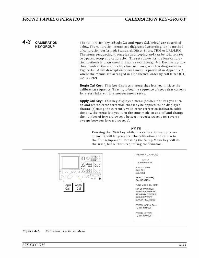
4-3 CALIBRATIONKEY-GROUP
The Calibration keys (Begin Cal and Apply Cal, below) are describedbelow. The calibration menus are diagramed according to the methodof calibration performed: Standard, Offset-Short, TRM or LRL/LRM.The menu sequencing is complex and looping and can be said to havetwo parts: setup and calibration. The setup flow for the four calibra-tion methods is diagramed in Figures 4-3 through 4-6. Each setup flowchart leads to the main calibration sequence, which is diagramed inFigure 4-6. A full description of each menu is provided in Appendix A,where the menus are arranged in alphabetical order by call letter (C1,C2, C3, etc).
Begin Cal Key: This key displays a menu that lets you initiate thecalibration sequence. That is, to begin a sequence of steps that correctsfor errors inherent in a measurement setup.
Apply Cal Key: This key displays a menu (below) that lets you turnon and off the error correction that may be applied to the displayedchannel(s) using the currently valid error-correction indicator. Addi-tionally, the menu lets you turn the tune mode on and off and changethe number of forward sweeps between reverse sweeps (or reversesweeps between forward sweeps).
NOTEPressing the Clear key while in a calibration setup or se-quencing will let you abort the calibration and return tothe first setup menu. Pressing the Setup Menu key will dothe same, but without requesting confirmation.
37XXXC OM 4-11
FRONT PANEL OPERATION CALIBRATION KEY-GROUP
MENU CAL_APPLIED
APPLYCALIBRATION
APPLY ON (OFF)CALIBRATION
FULL 12-TERM(S11, S21S22, S12)
TUNE MODE ON (OFF)
NO. OF FWD (REV)SWEEPS BETWEENREV (FWD) SWEEPSXXXXX SWEEPS(XXXXX REMAINING)
PRESS <APPLY CAL>TO TURN ON/OFF
PRESS <ENTER>TO TURN ON/OFF
ApplyCal
BeginCal
Figure 4-2. Calibration Key Group Menu
Standard Calibration Setup Flow—Description
1. Pressing the Begin Cal key calls Menu C11.
2. With one exception, the flow is from left to right in the direction ofthe arrow head. The exception occurs in Menu C1, for the TIMEDOMAIN choice. Here the flow direction reverses to Menu C2Cthen returns to a left-to-right flow on to Menu C3 or C3D.
3. Arrowheads that point both left and right indicate that the flowreturns to the right-most menu after a choice had been made.
4. The group of menus to the left of Menu C3 and C3D are the initialselection set and are essentially the same for all four calibrationtypes: Standard, Offset-Short, TRM, and LRL/LRM.
5. The group of menus that follow Menu C3 or C3D are, for the mostpart, type specific. The selection of Menu C3 or C3D depends uponthe choice made in Menu C11A: COAXIAL or MICROSTRIP. Forthe Standard Calibration, the WAVEGUIDE selection in MenuC11A is not used.
CALIBRATION KEY-GROUP FRONT PANEL OPERATION
4-12 37XXXC OM

37XXXC OM 4-13
FRONT PANEL OPERATION CALIBRATION KEY-GROUP
! " # $ %
& $ % ' ( (
)
)
* * *
+ * *
, -
. / * , -
*
0
,
/
*
/ 1
* -
2 2
& $ % ' ( (
& $ % ' ( (
& # 3 0 (
* .
*
/
)
+ *
*
* * + *
)
/
*
)
*
* + *
*
1 /
1
1
*
+ + + 4 4
/ 1
1
/ 1
/
0
*
5 6 & 7 6 *
) )
, ,
* 5 2 2 * 5 2 2
5 6 & 7 6 *
8 2 2
5 . 08 . 5 )
0 . *8 . 0 ,
* . 8 . *
. -8 . )
* 6 & 7 6 *
2 2
* 6 & 7 6 *
,
- 9
) 9
* ) 9
9
,
2 2
9 2 2
- -
: ; <
& 7
*
/ +
/ 1
/ + / 1
1
/
& # 3 6 * (
& # 3 6 * (
/
1
1
1 :
* 6
, - = - 5 - * - - )
1
1 :
1
, - = - 5 - * - - )
*
/
. -. . *
* . . . * 5
0 . *. . 0 0
5 . 0. . 5 *
,
<
9
>
9 . 9 .
. .
. .
. 0 ) . 0 )
.
0
. .
. .
5
?
& # 3 0 & 7 ( ( (
Figure 4-3. Menu Sequencing, Standard Calibration
* Setup Menu SU1/SU3 – See Figure 4-6** Cal Seq (Calibration Sequence) – See Figure 4-5*** Reflection Pairing Menu C13A or C13B – See Figure 4-4
SSLT and SSST (Offset-Short)Calibration Setup Flow—Description
1. Pressing the Begin Cal key calls Menu C13.
2. With one exception, the flow is from left to right in the direction ofthe arrow head. The exception occurs in Menu C1, for the TIMEDOMAIN choice. Here the flow direction reverses to Menu C2Cthen returns to a left-to-right flow on to Menu C3A, C3C, or C3B.
3. Arrowheads that point both left and right indicate that the flowreturns to the right-most menu after a choice had been made.
4. The group of menus to the left of Menu C3A, C3C, or C3B are theinitial selection set and are essentially the same for all fourcalibration types: Standard, Offset-Short, TRM, and LRL/LRM.
5. The group of menus that follow Menu C3A, C3C, or C3B are, forthe most part, type specific. The selection of Menu C3A, C3C, orC3B depends upon the choice made in Menu C11A: COAXIAL,WAVEGUIDE, or MICROSTRIP.
CALIBRATION KEY-GROUP FRONT PANEL OPERATION
4-14 37XXXC OM

37XXXC OM 4-15
FRONT PANEL OPERATION CALIBRATION KEY-GROUP
! "
#
$ %
#
& &
&$ %
' &$ ' ' %
$ ( ' ' %
$ ) *
$ %
+ , $ ' ) * %
$ %
'
-
, - .
" / 0 1
' +
&
'
, &
&
#
$ ( ' %
'
&
2 $ ' ' ( ' %
#
, &
$ ' %
#
2 $ ' %
$ ' ( ' %
#
+ 3 +
2 - 3
, 4 - .
5 5
' 5 5
2 - 3
)
* 3
# 3
' # 3
3
" / 6 '
'
-
- 2 - . ,
$ % - .
- .
'
2
, (
, - .
, ( , - .
$ % - .
0
2
,
'
( ( ( 7 - 7
, - .
- .
$ %
, - .
- $ %
2 ,
#
2 -
2 - , - .
- 5 5
- ' 5 5
)
5 5
3 5 5
2
$ * * %
8 9 :
, -
- .
- .
0
$ % - . 8
' 6
) * ; * < * ' * * #
- .
- . 8
- .
) * ; * < * ' * * #
'
, -
0
-
3 -
- &
2
& 4
0
2 -
- &
$ %
&
$ %
$ %
1
-
+ $ %
' + $ %
-
&
-
-
<
&
+ $ % + $ %
$ % $ %
$ % $ %
$ % $ %
<
&
$ % $ %
$ % $ %
$ % $ %
'
* = + ' >?
= + ' < 0 . >?
' = + 1 1 0 . ' >?
1 = + < ' 0 . 1 >?
-
- ? 5 5
'
'
* = + ' >?
= + ' < 0 . >?
' = + 1 1 0 . ' >?
1 = + < ' 0 . 1 >?
-
- ? 5 5
'
1
* = + ' >?
= + ' < 0 . >?
' = + 1 1 0 . ' >?
1 = + < ' 0 . 1 >?
-
- ? 5 5
#
2 - 3
+ 3 +
4
, 4 - .
4? 5 5
' 4? 5 5
1 4? 5 5
2 - 3
#
2 - 3
2 - , - .
- ? 5 5
- ' ? 5 5
- 1 ? 5 5
@
@
1
-
'
-
&
-
-
1
-
2 -
-
&
-
-
" / 6 '
" / 6 '
' *
-
- 5 5
-
)
:
)
&
- $ & , %
1
$ + ' ( ' + %
$ + ( ' + ' %
-
1
$ + ' ( ' + 1 ( 1 + %
$ + ( ' + ' ( 1 + 1 %
-
@
@
Figure 4-4. Menu Sequencing, SSLT and SSST(Offset-Short) Calibration

LRL/LRM Calibration Setup Flow—Description
1. Pressing the Begin Cal key calls Menu C15.
2. With one exception, the flow is from left to right in the direction ofthe arrow head. The exception occurs in Menu C1, for the TIMEDOMAIN choice. Here the flow direction reverses to Menu C2Cthen returns to a left-to-right flow on to Menu C3E, C3G, or C3F.
3. Arrowheads that point both left and right indicate that the flowreturns to the right-most menu after a choice had been made.
4. The group of menus to the left of Menu C3E, C3G, or C3F are theinitial selection set and are essentially the same for all fourcalibration types: Standard, Offset-Short, TRM, and LRL/LRM.
5. The group of menus that follow Menu C3E, C3G, or C3F are, forthe most part, type specific. The selection of Menu C3E, C3G, orC3F depends upon the choice made in Menu C11A: COAXIAL,WAVEGUIDE, or MICROSTRIP.
CALIBRATION KEY-GROUP FRONT PANEL OPERATION
4-16 37XXXC OM
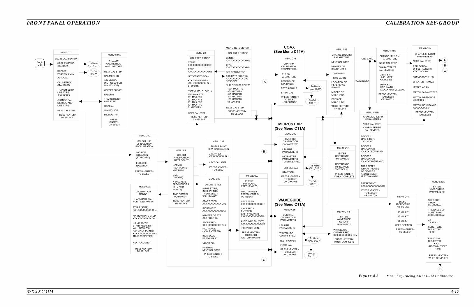
37XXXC OM 4-17
FRONT PANEL OPERATION CALIBRATION KEY-GROUP
!
"
# ! $ $
%
& '
& '
# !
# ! (
' ) * + , - -
' ) * + , - -
' ) * + , - -
%
%
+ . / 0 ) *
' ) * + , - -
1
2 3
! !
4 5 2 3
5
! !
! ! ! 6
' + 0 7 -
1
! 6
%
2
3 8
1 8
5 1 8
8
2
! $ $
8 ! $ $
!
!
! 3 3
& 9 ! (
' + 0 7 : 5 -
' + 0 7 : 5 -
' + 0 7 : 5 -
&
8 ! &
5
!
5 !
!
! $ $
5 ! $ $
&
5
! 6
! 6
! 6
5
;
! ! 6
! ; ! 6
! 6
5
; ; ; < <
! 6
! 6
! 6
! 6
! 6 &
! 6
2 3 3 = 3 5 3 3 1
5
! 6
! 6
! 6 &
5 :
2 3 3 = 3 5 3 3 1
8
%
% >
Figure 4-5. Menu Sequencing, LRL/LRM Calibration

TRM Calibration Setup Flow—Description
1. Pressing the Begin Cal key calls Menu C17.
2. With one exception, the flow is from left to right in the direction ofthe arrow head. The exception occurs in Menu C1, for the TIMEDOMAIN choice. Here the flow direction reverses to Menu C2Cthen returns to a left-to-right flow on to Menu C3H, C3J, or C3I.
3. Arrowheads that point both left and right indicate that the flowreturns to the right-most menu after a choice had been made.
4. The group of menus to the left of Menu C3H, C3J, or C3I are theinitial selection set and are essentially the same for all fourcalibration types: Standard, Offset-Short, TRM, and LRL/LRM.
5. The group of menus that follow Menu C3H, C3J, or C3I are, for themost part, type specific. The selection of Menu C3H, C3I, or C3Jdepends upon the choice made in Menu C11A: COAXIAL,WAVEGUIDE, or MICROSTRIP.
CALIBRATION KEY-GROUP FRONT PANEL OPERATION
4-18 37XXXC OM
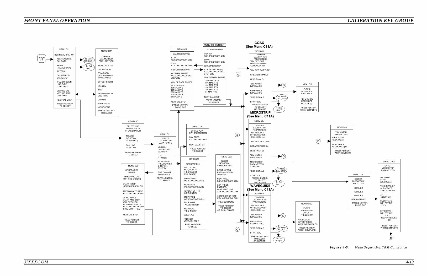
37XXXC OM 4-19
FRONT PANEL OPERATION CALIBRATION KEY-GROUP
!
" #
$ % & ' ( (
$ % & ' ( (
$ % & ' ( (
& ) * + $ %
$ % & ' ( (
,
- .
- " / 0 "
- " .
1 ! - 2 " / 0 " .
- .
"
2
! 3
& + 4 " 5 (
" ,
! 3
!
" /
" 0 6
" , 6
2 , 6
6
" /
6
-
" 0 0 .
7 8
& + 4 9 2 (
& + 4 9 2 (
& + 4 9 2 (
2
3 !
- . 3
3
2
! :
! 3
! : ! 3
- . 3
5
!
2
: : : ; ;
! 3
3
- .
! 3
- .
!
3
3
3
" / 0 " < 0 " = 0 " 2 0 " " 0 " , "
!
3
3
5
- . 3
2 9
" / 0 " < 0 " = 0 " 2 0 " " 0 " , "
!
5
" "
5
- .
2 " "
6
>
/
8
Figure 4-6. Menu Sequencing, TRM Calibration
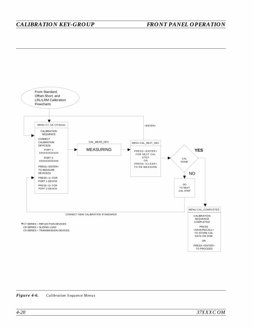
CALIBRATION KEY-GROUP FRONT PANEL OPERATION
4-20 37XXXC OM
MENU C7, C8, C9 Series
CALIBRATIONSEQUENCE
CONNECTCALIBRATIONDEVICE(S)
PORT 1:XXXXXXXXXXXX
PORT 2:XXXXXXXXXXXX
PRESS <2> FORPORT 2 DEVICE
PRESS <ENTER>TO MEASUREDEVICE(S)
PRESS <1> FORPORT 1 DEVICE
MEASURING
MENU CAL_NEXT_DEV
CALDONE
GOTO NEXT
CAL STEP
<ENTER>
YES
NO
CONNECT NEW CALIBRATION STANDARDS
C7 SERIES = REFLECTION DEVICESC8 SERIES = SLIDING LOADC9 SERIES = TRANSMISSION DEVICES
*
From Standard,Offset-Short, andLRL/LRM CalibrationFlowcharts
MENU CAL_COMPLETED
OR
CALIBRATIONSEQUENCE
COMPLETED
PRESS<SAVE/RECALL>TO STORE CALDATA ON DISK
PRESS <ENTER>TO PROCEED
CAL_MEAS_DEV
PRESS <ENTER >FOR NEXT CAL
STEPOR
PR ESS <C LEAR >TO R E-MEASURE
Figure 4-6. Calibration Sequence Menus
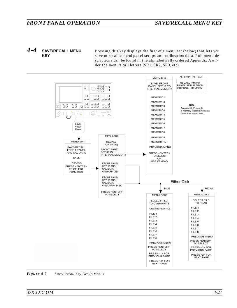
4-4 SAVE/RECALL MENUKEY
Pressing this key displays the first of a menu set (below) that lets yousave or recall control panel setups and calibration data. Full menu de-scriptions can be found in the alphabetically ordered Appendix A un-der the menu’s call letters (SR1, SR2, SR3, etc).
37XXXC OM 4-21
FRONT PANEL OPERATION SAVE/RECALL MENU KEY
& $ ! # #
! + ,
&
) & *
! ! (
! + ,
! ! # # " # #
! ! # # ! ! ( #
:
(
(
( :
( >
& ! !
(
! + ,
( ! #
( >
( 6
( 4
( -
( B
( G
( 7
! &
! ! ( .
&
# :
! &
! + ,
& %
%
! + , ! & ! '
! + , ! '
:
>
4
6
-
B
#
! &
! + ,
#
! + , ! & ! '
! + , ! '
:
>
4
6
-
B
1 I # 1 J
- B G
> 4 6
:
7 . 8
K $
&
J 1 J ) 3 * L < < 1 1 1 J I 1 I J J .
Figure 4-7 Save/Recall Key-Group Menus

4-5 MEASUREMENTKEY-GROUP
The individual keys within the Measurement key-group are describedbelow. Flowcharts of the Setup Key and Data Points key menus areshown in Figure 4-8. As described for the calibration menus, the flowis left-to-right and the double arrowhead lines indicate that the flowreturns to the calling menu once a selection has been made. Full menudescriptions can be found in the alphabetically ordered Appendix Aunder the menu’s call letters (SU1, SU2, DF, etc).
Setup Menu Key: Pressing this key calls Sweep Setup Menu SU1 orSU3. Depending upon which menu items you select, additional menusmay also be called.
Data Points Key: Pressing this key calls Menu SU9 or SU9A. MenuSU9 provides for data point selection. Menu SU9A is called if the C.W.MODE selection in Menu SU1 is on.
Hold Key: If the instrument is sweeping, pressing this key results inan immediate halt of the sweep at the current data point. The LED onthe button lights, indicating that the Hold Mode is active.
If you restart the sweep after performing any recall-from-disk opera-tions in the Hold Mode (sweep stopped at some data point), the sweeprestarts from the beginning. The instrument may be taken out of thehold mode as follows:
By pressing the Default Program key. This causes the 37XXXC torevert to a predefined state
By pressing the Begin Cal key. This causes the 37XXXC to re-sume sweeping and begin the Calibration Menu sequence
NOTESee the description for Menu SU4 for a discussion of theinteraction between the Hold Mode and the selection of“Single Sweep” or “Restart Sweep.”
Domain Key: This key function is fully described in paragraph 4-2(page 4-8). Additionally, if the Time Domain option is installed, makinga selection other than “Frequency Domain” lets you display measureddata in the time domain. It also calls a further sequence of Time Do-main Menus. Refer to paragraph 9-2 for additional details.
Appl: Pressing this key calls a menu that lets you select the followingapplications: Adapter Removal, Swept Frequency Gain Compression,or Swept Power Gain Compression.
MEASUREMENT KEY-GROUP FRONT PANEL OPERATION
4-22 37XXXC OM
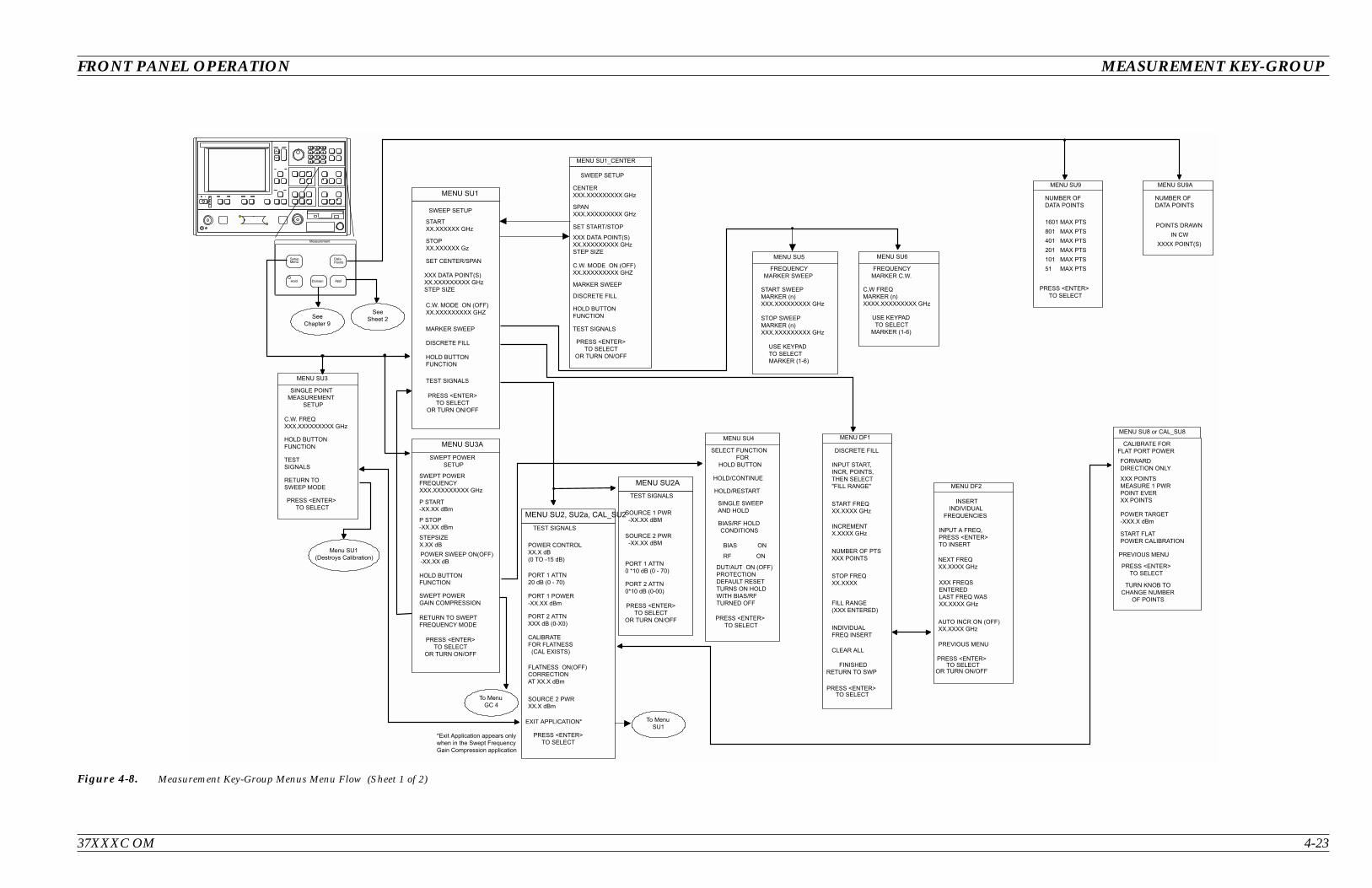
37XXXC OM 4-23
FRONT PANEL OPERATION MEASUREMENT KEY-GROUP
MENU SU8 or CAL_SU8
PREVIOUS MENU
CALIBRATE FOR
FLAT PORT POWER
FORWARD
DIRECTION ONLY
XXX POINTS
MEASURE 1 PWR
POINT EVER
XX POINTS
POWER TARGET
-XXX.X dBm
START FLAT
POWER CALIBRATION
PRESS <ENTER>TO SELECT
MENU DF1
DISCRETE FILL
INPUT START,
INCR, POINTS,
THEN SELECT
"FILL RANGE"
START FREQ
XX.XXXX GHz
INCREMENT
X.XXXX GHz
NUMBER OF PTS
XXX POINTS
STOP FREQ
XX.XXXX
FILL RANGE
(XXX ENTERED)
INDIVIDUAL
FREQ INSERT
CLEAR ALL
FINISHED
RETURN TO SWP
Measurement
DataPoints
Hold Domain
SetupMenu
See
Chapter 9
Menu SU1
(Destroys Calibration)
PRESS <ENTER>TO SELECT
OR TURN ON/OFF
MENU DF2
NEXT FREQ
XX.XXXX GHz
INSERT
INDIVIDUAL
FREQUENCIES
INPUT A FREQ,
PRESS <ENTER>
TO INSERT
XXX FREQS
ENTERED
LAST FREQ WAS
XX.XXXX GHz
AUTO INCR ON (OFF)
XX.XXXX GHz
PREVIOUS MENU
MENU SU9
PRESS <ENTER>
TO SELECT
NUMBER OF
DATA POINTS
1601 MAX PTS
801 MAX PTS
401 MAX PTS
201 MAX PTS
101 MAX PTS
51 MAX PTS
MENU SU9A
NUMBER OF
DATA POINTS
POINTS DRAWN
IN CW
XXXX POINT(S)
MENU SU3
SINGLE POINT
MEASUREMENT
SETUP
C.W. FREQ
XXX.XXXXXXXXX GHz
HOLD BUTTON
FUNCTION
TEST
SIGNALS
RETURN TO
SWEEP MODE
PRESS <ENTER>
TO SELECT
MENU SU5
FREQUENCY
MARKER SWEEP
START SWEEP
MARKER (n)
XXX.XXXXXXXXX GHz
STOP SWEEP
MARKER (n)
XXX.XXXXXXXXX GHz
USE KEYPAD
TO SELECT
MARKER (1-6)
MENU SU6
FREQUENCY
MARKER C.W.
C.W FREQ
MARKER (n)
XXXX.XXXXXXXXX GHz
USE KEYPAD
TO SELECT
MARKER (1-6)
MENU SU1
SWEEP SETUP
MARKER SWEEP
DISCRETE FILL
START
XX.XXXXXX GHz
STOP
XX.XXXXXX Gz
XXX DATA POINT(S)
XX.XXXXXXXXX GHz
STEP SIZE
C.W. MODE ON (OFF)
XX.XXXXXXXXX GHZ
HOLD BUTTON
FUNCTION
TEST SIGNALS
PRESS <ENTER>
TO SELECT
OR TURN ON/OFF
SET CENTER/SPAN
SWEEP SETUP
CENTER
XXX.XXXXXXXXX GHz
SPAN
XXX.XXXXXXXXX GHz
SET START/STOP
C.W. MODE ON (OFF)
XX.XXXXXXXXX GHZ
XXX DATA POINT(S)
XX.XXXXXXXXX GHz
STEP SIZE
MARKER SWEEP
DISCRETE FILL
HOLD BUTTON
FUNCTION
TEST SIGNALS
PRESS <ENTER>
TO SELECT
OR TURN ON/OFF
MENU SU1_CENTER
MENU SU4
HOLD/CONTINUE
HOLD/RESTART
SELECT FUNCTION
FOR
HOLD BUTTON
SINGLE SWEEP
AND HOLD
BIAS/RF HOLD
CONDITIONS
PRESS <ENTER>
TO SELECT
BIAS ON
RF ON
DUT/AUT ON (OFF)
PROTECTION
DEFAULT RESET
TURNS ON HOLD
WITH BIAS/RF
TURNED OFF
PRESS <ENTER>
TO SELECT
TURN KNOB TO
CHANGE NUMBER
OF POINTS
Appl
MENU SU3A
SWEPT POWER
SETUP
RETURN TO SWEPT
FREQUENCY MODE
P START
-XX.XX dBm
POWER SWEEP ON(OFF)
-XX.XX dB
HOLD BUTTON
FUNCTION
PRESS <ENTER>
TO SELECT
OR TURN ON/OFF
STEPSIZE
X.XX dB
SWEPT POWER
FREQUENCY
XXX.XXXXXXXXX GHz
P STOP
-XX.XX dBm
SWEPT POWER
GAIN COMPRESSION
To Menu
GC 4
See
Sheet 2
MENU SU2A
TEST SIGNALS
SOURCE 1 PWR
-XX.XX dBM
PORT 1 ATTN
0 *10 dB (0 - 70)
PORT 2 ATTN
0*10 dB (0-00)
PRESS <ENTER>
TO SELECT
OR TURN ON/OFF
.
MENU SU2, SU2a, CAL_SU2
TEST SIGNALS
POWER CONTROL
XX.X dB
(0 TO -15 dB)
SOURCE 2 PWR
XX.X dBm
PORT 1 POWER
-XX.XX dBm
PORT 2 ATTN
XXX dB (0-X0)
PRESS <ENTER>
TO SELECT
CALIBRATE
FOR FLATNESS
(CAL EXISTS)
FLATNESS ON(OFF)
CORRECTION
AT XX.X dBm
PORT 1 ATTN
20 dB (0 - 70)
EXIT APPLICATION*
SOURCE 2 PWR
-XX.XX dBM
To Menu
SU1
*Exit Application appears only
when in the Swept Frequency
Gain Compression application
Figure 4-8. Measurement Key-Group Menus Menu Flow (Sheet 1 of 2)
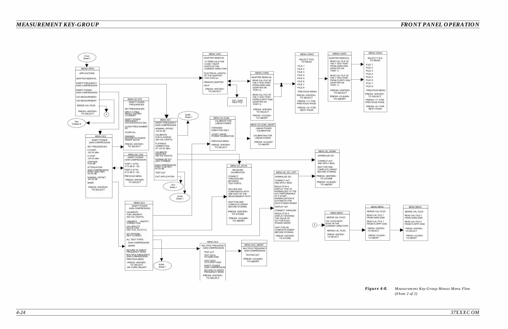
4-24 37XXXC OM
MEASUREMENT KEY-GROUP FRONT PANEL OPERATION
!
" !
#
$
$
%
"
&
'
(
! $
) * + , - - . $
/ +
0 /
1 2 /
/ +
/
!
$ 3 4 $ 3 / 1 3 3 3 2
3 4 $ 3 / 1 3 3 3 2
%
"
#
#
$
$
5 6 7
#1 2
#1 2
#1 $ 2
%
#1 $ 2
, - - . $
1 2
$
/
/ +
1 2
0 $1 2
1 3 / 2 /
!
#
$
$
%
"
&
'
(
1 2
1 2
8
$ , - - . $
, - - . $
, - - . $
8
1 2
$ 1 2
0 0
0 $
! $ !
$
$
0 $
!
8
8
- - , 9 6 . - )
$
$ #
$ #
%
#
#
Figure 4-8. Measurement Key-Group Menus Menu Flow(Sheet 2 of 2)
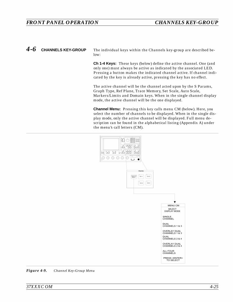
4-6 CHANNELS KEY-GROUP The individual keys within the Channels key-group are described be-low:
Ch 1-4 Keys: These keys (below) define the active channel. One (andonly one) must always be active as indicated by the associated LED.Pressing a button makes the indicated channel active. If channel indi-cated by the key is already active, pressing the key has no effect.
The active channel will be the channel acted upon by the S Params,Graph Type, Ref Plane, Trace Memory, Set Scale, Auto Scale,Markers/Limits and Domain keys. When in the single channel displaymode, the active channel will be the one displayed.
Channel Menu: Pressing this key calls menu CM (below). Here, youselect the number of channels to be displayed. When in the single dis-play mode, only the active channel will be displayed. Full menu de-scription can be found in the alphabetical listing (Appendix A) underthe menu’s call letters (CM).
37XXXC OM 4-25
FRONT PANEL OPERATION CHANNELS KEY-GROUP
# ! ( #
' "
# " D :
& ( # " D :
# " D >
& ( # " D >
"
! + ,
I
I
I >
I J
- B G
> 4 6
:
7 . 8
#
I
I :
Figure 4-9. Channel Key-Group Menu

4-7 DISPLAY KEY-GROUP The individual keys within the Display key-group are described below.Menu flow diagrams are shown in Figure 4-10. Full menu descrip-tion(s) for menu SP and all others mentioned below can be found inthe Appendix A alphabetical listing under the menu’s call letters (SP,GT1, RD1, etc.).
Graph Type Key: Pressing this key calls menu GT1 or GT2. Thesemenus let you select the type of display to appear on the active chan-nel for the selected S-Parameter.
Set Scale Key: Pressing this key calls the appropriate scaling menu(SS1, SS2, SS3, etc.) depending upon the graph type being displayedon the active channel for the selected S-Parameter.
Auto Scale Key: Pressing this key autoscales the trace or traces forthe active channel. The new scaling values are then displayed on themenu (if it is displayed) and graticule. The resolution will be selectedfrom the normal sequence of values you have available using the knob.When the active channel has a Real and Imaginary type display, thelarger of the two signals will be used to autoscale both the real andimaginary graphs. Both graphs will be displayed at the same resolu-tion.
S Params Key: Pressing this key calls menu SP. This menu allowsyou to select the S-Parameter to be displayed by the active channel forthe selected S-Parameter.
Ref Plane Key: Pressing this key calls menu RD1. This menu lets youinput the reference plane in time or distance. You do this by selectingthe appropriate menu item. For a correct distance readout, the dielec-tric constant must be set to the correct value. This is accomplished byselecting SET DIELECTRIC, which calls menu RD2.
DISPLAY KEY-GROUP FRONT PANEL OPERATION
4-26 37XXXC OM
On menu RD1, selecting AUTO automatically adjusts the reference de-lay to unwind the phase for the active channel.
The 37XXXC unwinds the phase as follows:
First, it sums the phase increments between each pair of mea-sured data points, then it takes the average “Pdelta” over the en-tire set of points
Next, it corrects the phase data by applying the following for-mula:
P P NxPcorrect measured delta
Where P = phase
Assuming there are fewer than 360 degrees of phase rotation betweeneach data point, the operation described above removes any net phaseoffset. The endpoints of the phase display then fall at the same phasevalue.
Trace Memory Key: Pressing this key brings up menu NO1. Thismenu—which relates to the active channel—allows you to store datato memory, view memory, perform operations with the stored memory,and view both data and memory simultaneously. Four memories exist,one for each channel. This allows each channel to be stored and nor-malized independent of the other channels. Data from the trace mem-ory may be stored on the disk or recalled from it.
NOTETrace memory will automatically be set to VIEW DATA(that is, turned off), if a sweep with a greater number ofpoints is selected while operating on a stored trace.
37XXXC OM 4-27
FRONT PANEL OPERATION DISPLAY KEY-GROUP
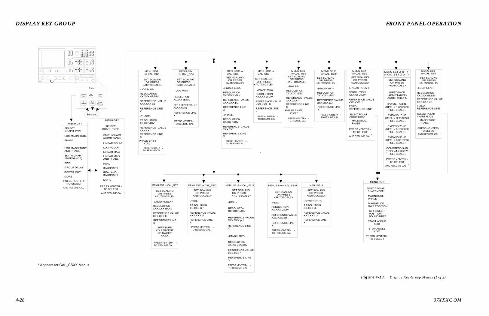
4-28 37XXXC OM
DISPLAY KEY-GROUP FRONT PANEL OPERATION
! !
" "
" "
# # $ # # # % &
' & # # # $ # # # (
# # $ # # ) % &
' & # # # $ # # )
" "
# # $ # # # % &
' & # # # $ # # # (
" "
# # $ # # # * % &
' & # # # $ # # # *
' # $ # # )
" "
# # $ # # # % &
' & # # # $ # # # (
" "
# # $ # # # % &
' & # # # $ # # #
+ +
, ,
- -
. / . /
0 0
' #
" "
" "
# # $ # # # 1 2 % &
' & # # # $ # # # 1 2
3 3
" "
# # $ # # # %
' & # # # $ # # #
" "
" "
4
# # $ # # # % &
' & # # # $ # # # (
# # $ # # % &
" "
# # $ # # # % &
4 4 . .
' & # # # $ # # # )
' & # # # $ # # # (
" "
# # # $ # # # 5 % &
' & # # # $ # # # 5
# $ # '
# # $ # #
" "
" "
# # $ # # # 1 2 % &
' & # # # $ # # # 1 2
' #
# # $ # # ) % &
' & # # # $ # # )
' # $ # # )
* ( ( 6 5 # # 7 8
" "
' 9 $ 4 4 4 4 4 4 4
'
# 4 1 2 ' 9 $ . 0 3 ,
'
# 4 1 2 ' 9 4 $ 4 4 4 4 4 4
'
# . 4 1 2 ' 9 4 $ 4 . 0 ,
'
. 1 2 ' 9 $ ! - . 3 -
'
*
*
*
*
*
*
*
*
*
*
**
*
# # $ # # # 1 2 % &
' & # # # $ # # # 1 2
2
# $ # #
# $ # #
3 , +
! - 0
.
4 $ "
: ( ; 6 <
6 ( < (
8 = 6 ;
6 6 >
5 ; 6 7
6 = > <
= 6 ;
*
*
*
' #
' #
' # '
#
' # '
' #
' #
' #
' #
?
' # '
?
' #
' #
' #
" "
# # $ # # # %
' & # # # $ # # #
!
' #
Figure 4-10. Display Key-Group Menus (1 of 2)
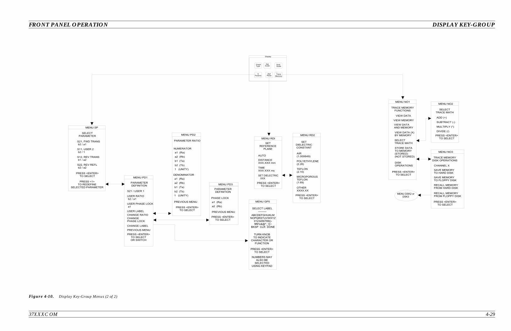
37XXXC OM 4-29
FRONT PANEL OPERATION DISPLAY KEY-GROUP
: ( ; 6 <
6 ( < (
= 6 ;
8 = 6 ;
$ 4 4 4 0 ! +
$ 0
' $ 4
' $ 0 +
# # # # $ # #
# # #
'
# # # $ # # # > >
# # # $ # # # >
&
&
'
&
& # 2
@
A
2 "
*
& %
.
#
' @
@
& @
& ' @
' ' @
? ' B % 6
? B %
? & B % 6
? & ' B % 6
@ @ .
'
6 6
&
6 B
B 6
B B
6 6
6 B
B 6
B B
2 " " " " " " " " "
@ 2
'
2 2
@
-
2 ' C @ D & # /
4 . ! - 0 3 , + "E F G H I J K L M N O
2 @
'
%
B % 6
@ 6
@
2
&
2
.
6 6
&
6 B
'
@
6 6 >
5 ; 6 7
6 = > <
Figure 4-10. Display Key-Group Menus (2 of 2)
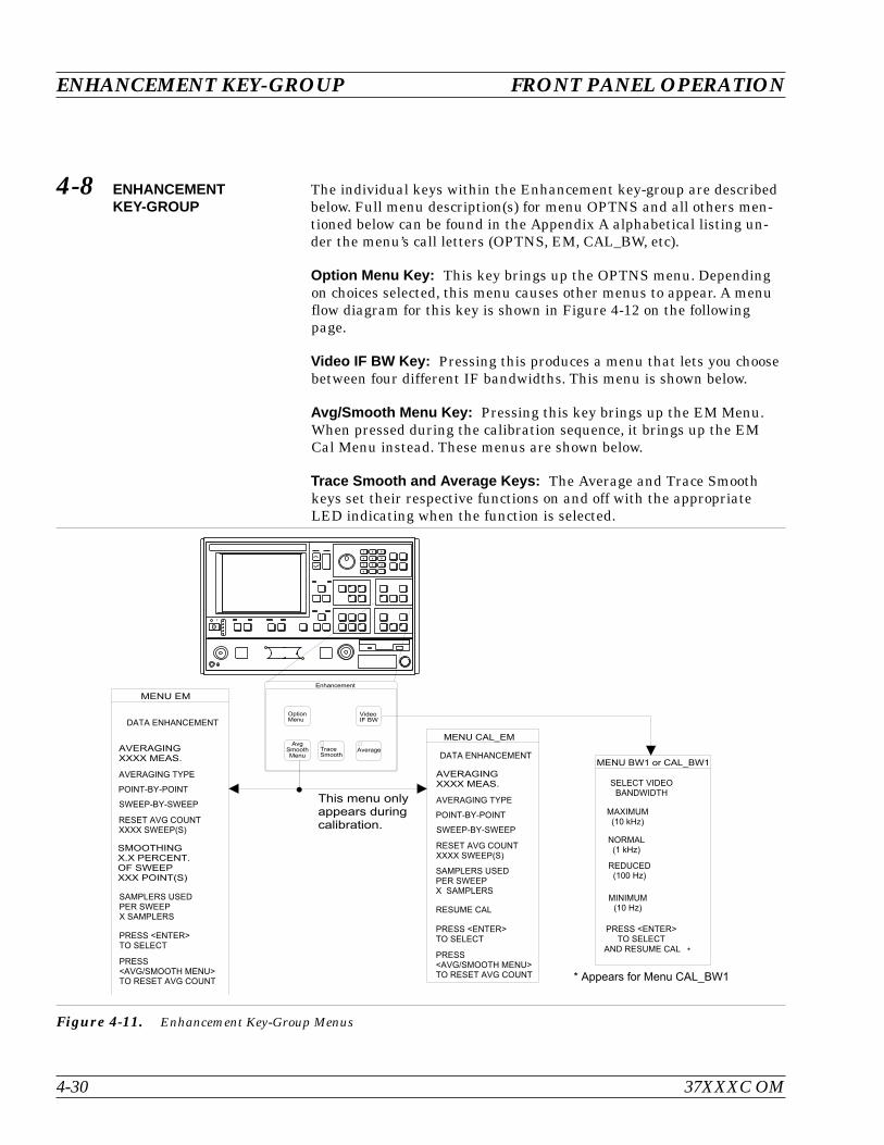
4-8 ENHANCEMENTKEY-GROUP
The individual keys within the Enhancement key-group are describedbelow. Full menu description(s) for menu OPTNS and all others men-tioned below can be found in the Appendix A alphabetical listing un-der the menu’s call letters (OPTNS, EM, CAL_BW, etc).
Option Menu Key: This key brings up the OPTNS menu. Dependingon choices selected, this menu causes other menus to appear. A menuflow diagram for this key is shown in Figure 4-12 on the followingpage.
Video IF BW Key: Pressing this produces a menu that lets you choosebetween four different IF bandwidths. This menu is shown below.
Avg/Smooth Menu Key: Pressing this key brings up the EM Menu.When pressed during the calibration sequence, it brings up the EMCal Menu instead. These menus are shown below.
Trace Smooth and Average Keys: The Average and Trace Smoothkeys set their respective functions on and off with the appropriateLED indicating when the function is selected.
ENHANCEMENT KEY-GROUP FRONT PANEL OPERATION
4-30 37XXXC OM
I 1 J < J 1 0 1 1 .
# "
& ' ' .
" ' . ! . % ! ! ) *
/ % ? / %
& # / # % # "
) 7 " ; *
) " ; *
# #) 7 7 " ; *
) 7 " ; *
! + ,
?
# "
I <
1
& 1 / %
K 0 < I
K 0 < I
# 3
3 J N ? / %
- B G
> 4 6
:
7 . 8
& ' ' ( !
! 8 / ( 8 !
% ! 8 / ( 8 % !
& ' % ! ) *
! #! % ! !
! + ,
! + & ' $ " , & '
& ' ' .
& ' ' ( !
! 8 / ( 8 !
% ! 8 / ( 8 % !
& ' % ! ) *
! #! % ! !
! + ,
! + & ' $ " , & '
Figure 4-11. Enhancement Key-Group Menus

37XXXC OM 4-31
FRONT PANEL OPERATION ENHANCEMENT KEY-GROUP
!
"
# #
$
%
%
& !
!
&
!
' &
(
' &
(
&
&
# #
# #
# #
) #
) ! #
# * * *
* # * *
&
# #
( # +
# #
, - ) , . / 0 / , 1
2 3 / 4
!
( # +
( # +
(
%
(
5
!
# #
(
(
(
( # +
5
!
'
!
(
!
!
'
!
%
6 1 2 4 , / , 7
8 9 0 4 4 1 - / , 7
: ) . / 0 4 4 1 - 8 / : ) 9 /
!
!
; :
% 5 < 5 '
< = >
' ?
! 5
* # "
;
@ A
" $
# #
%
! (
( ! ( $ # #
; ;
; ; 6 6 / ) : B 2 C 6 1 2 4 , ! 2 , B 1 ) D D / 3
! % ! ! '
/ / !
# B / .
Figure 4-12. Enhancement Key-Group (Options Menu Key)

4-9 HARD COPY KEY-GROUP The individual keys within the Hard Copy key-group are described be-low. Full descriptions for menus can be found in the alphabetical list-ing (Appendix A) under the menu’s call letters (PM1, PM2, PM3, etc.)
Menu Key: Pressing this key brings up menu PM1. This menu allowsyou to define what will happen every time you press the Start Printkey. A menu flow diagram is shown in Figure 4-13.
Start Print Key: Pressing this key starts outputting the measureddata as defined by the setup defined by the selected MENU key.
Stop Print Key: Pressing this key can result in any of the followingactions if the printer is selected:
If the printer is active, the key aborts the printing and sends aform feed command to the printer. Aborting the printing clearsthe print buffer
If the printer is not active and another form of output is active,pressing this key aborts printing, but does not send a form feedto the printer
Plotting Functions: The 37XXXC can plot an image of either the en-tire screen or subsets of it. Plots can be either full size or they can bequarter size and located in any of the four quadrants. You can selectdifferent pens for plotting different parts of the screen. You cannot,however, plot tabular data.
HARD COPY KEY-GROUP FRONT PANEL OPERATION
4-32 37XXXC OM
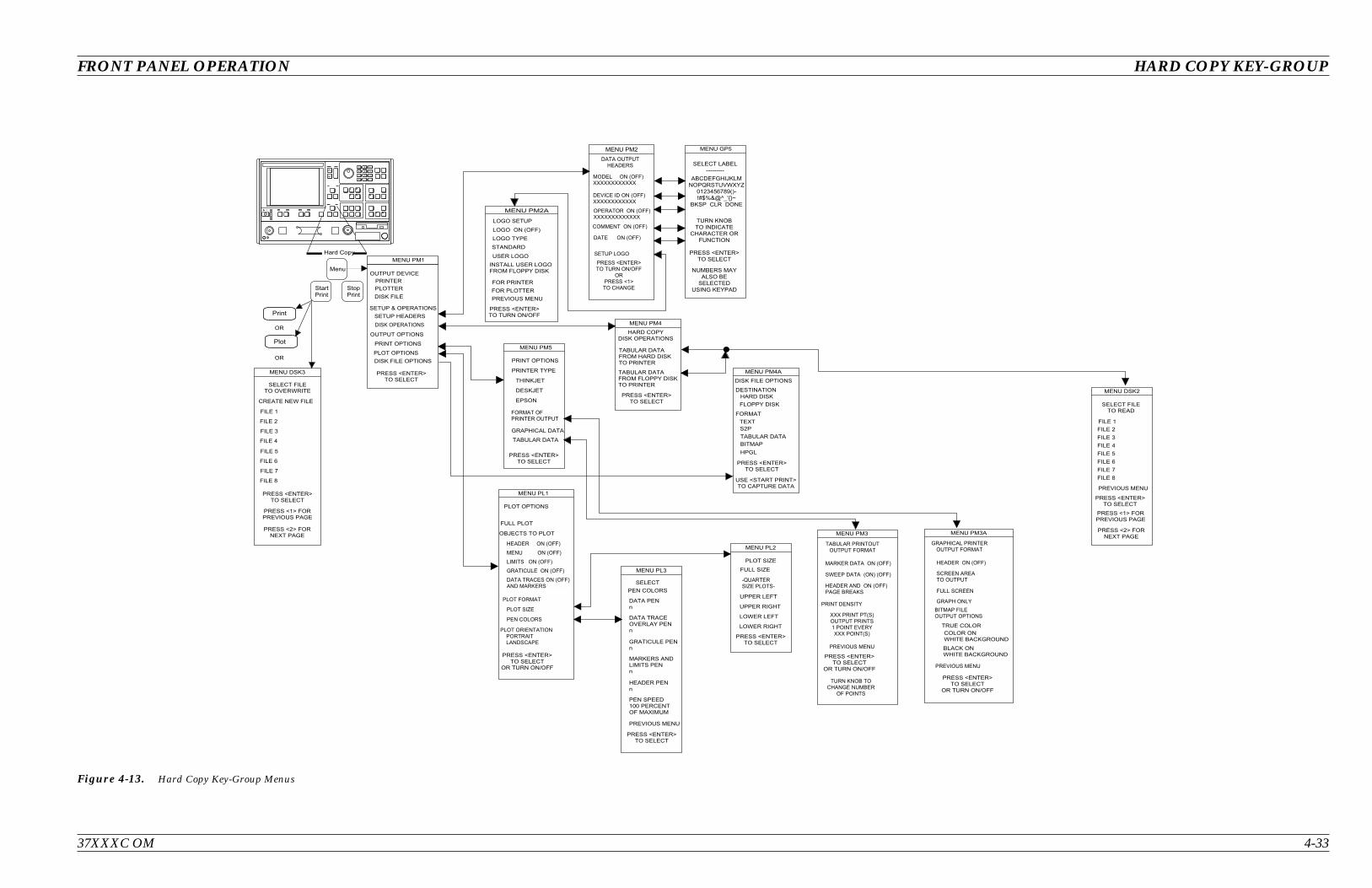
37XXXC OM 4-33
FRONT PANEL OPERATION HARD COPY KEY-GROUP
! "
#
#
$
$
% & # %
#
! % % % % % % % % %
!
! !
'
! " & $ #
( ' ) * + , %- . / 0 1 2 3 4 5 6 7 8
!
'
"
"
!
1
(
'
)
*
+
9 : ; < = >
? @
A 9 : A : B A
A < = : B A
!
$
!
! !
(
!
!
(
!
!
: B A
C < A
$
$ !
!
! $ !
$
(
'
)
*
+
* + ,
( ' )
D %
Figure 4-13. Hard Copy Key-Group Menus

4-10 SYSTEM STATEKEY-GROUP
The individual keys within the System State key-group are describedbelow. The menu flow for the Utility Menu key is shown in Figure 4-14on page 4-36. Full descriptions for menus can be found in thealphabetical listing (Appendix 1) under the menu’s call letters (U1, U2,U3, etc.)
Default Program Key: Pressing this key brings up the default menu.If pressed again, it recalls the factory selected default values for thecontrol panel controls. The values are defined in Table 4-2 on thefollowing page.
Pressing this key then the 1 key resets front panel key states and in-ternal memories 1 through 4.
Pressing this key then the 0 key resets front panel key states, internalmemories 1 through 10, and certain hardware settings.
NOTEUse of this key will destroy control panel and calibrationsetup data, unless they have been saved to disk.
Utility Menu Key: Pressing this key calls menu U1. This menu ac-cesses subordinate menus to perform system, disk, and system utili-ties. The only functions performed directly from the U1 Menu are“Blank Frequency Information.” and “Data Drawing.”
SYSTEM STATE KEY-GROUP FRONT PANEL OPERATION
4-34 37XXXC OM
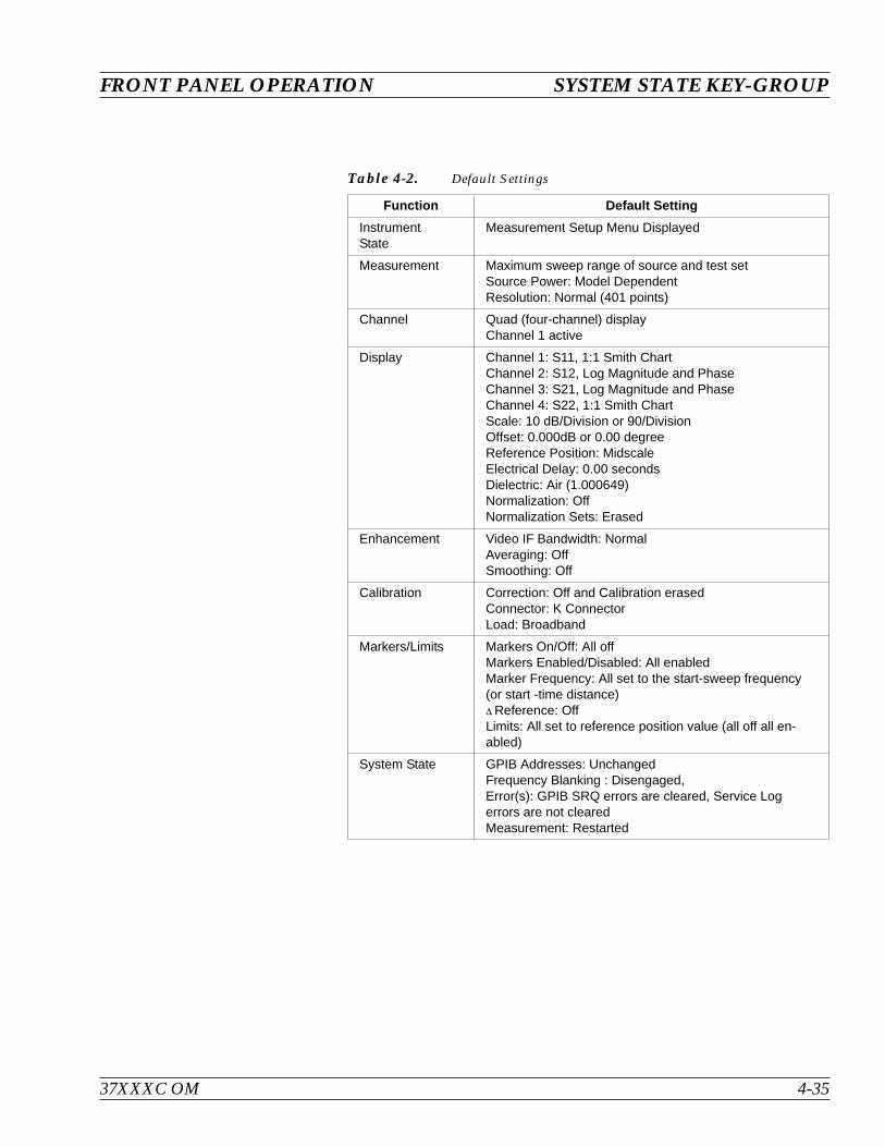
37XXXC OM 4-35
FRONT PANEL OPERATION SYSTEM STATE KEY-GROUP
Function Default Setting
InstrumentState
Measurement Setup Menu Displayed
Measurement Maximum sweep range of source and test setSource Power: Model DependentResolution: Normal (401 points)
Channel Quad (four-channel) displayChannel 1 active
Display Channel 1: S11, 1:1 Smith ChartChannel 2: S12, Log Magnitude and PhaseChannel 3: S21, Log Magnitude and PhaseChannel 4: S22, 1:1 Smith ChartScale: 10 dB/Division or 90/DivisionOffset: 0.000dB or 0.00 degreeReference Position: MidscaleElectrical Delay: 0.00 secondsDielectric: Air (1.000649)Normalization: OffNormalization Sets: Erased
Enhancement Video IF Bandwidth: NormalAveraging: OffSmoothing: Off
Calibration Correction: Off and Calibration erasedConnector: K ConnectorLoad: Broadband
Markers/Limits Markers On/Off: All offMarkers Enabled/Disabled: All enabledMarker Frequency: All set to the start-sweep frequency(or start -time distance) Reference: OffLimits: All set to reference position value (all off all en-abled)
System State GPIB Addresses: UnchangedFrequency Blanking : Disengaged,Error(s): GPIB SRQ errors are cleared, Service Logerrors are not clearedMeasurement: Restarted
Table 4-2. Default Settings
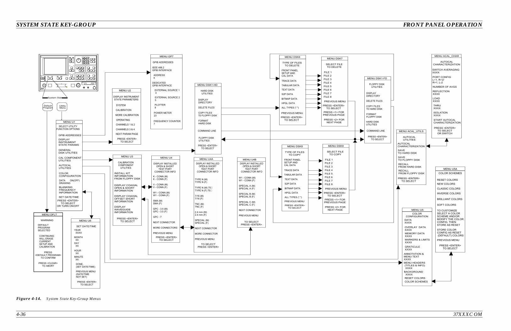
4-36 37XXXC OM
SYSTEM STATE KEY-GROUP FRONT PANEL OPERATION
!
"
" ! #
$ %
&
' ( )
*
+ ,
$ %
! - ' (! - ' (
. - ' (. - ' (
) / - ' () / - ' (
' ( ' (
- 0 1 2 ' ( - 0 1 2 ' (
- 3
4
.
"
4 + ,
4 ,
) .
$ %
! !
0
5
"
"
$ %
, / + 5
, 0 + *
4
)
) "
$ %
$ % "
! / - ,
, !
6 !
$ %
, !
!
! / -
!
6 , !
$ %
!
, !
&
7
&
, 4 4
4 4
4 4 4 4
, 4 4
4 4
8' & (
. ' & (
$ %
"
* 9 9 1 5 "
7
"
9
) 5 0
# 3
3
4 / *
4 5 2
! 3
/
5
.
$ %
$ / % .
$ 5 % 4
0
*
2
7
3
9
! 7
.
$ %
"
4
5
"
,
' : 1 : (
! 9
.
$ %
"
! ;
/
5
.
$ %
$ / % .
$ 5 % 4
0
*
2
7
3
9
4
5
"
,
' : 1 : (
/
3 9 ;
* 2 7
/ 5 0
6 1 -
<
, =
$ %
. , !
. !
, !
!
< ,
) , . 4 4 4 4
$ % ) ,
, =
> / 8 > 5 & > / 8 - 5
" .
4 4 4 4
4 4 4 4
, 4 4 4 4
4 4 4 4
, =
2
4 4 4 4
,
. 4 4 4 4
4 4 4 4
! + 4 4 4 4
4 4 4 4
+ 4 4 4 4 4
, ' + ( 4 4 4 4
" ! 4 4 4 4
2
,
)
.
"
= , & , 8 ,
' (
$ %
.
* "
$ %
) / - ' () / - ' (
' ( ' (
" ' ( " ' (
' ( ' (
4
.
*
$ %
' ( ' (
' ( 3 2 ' ( 3 2
3 & / 7 ' (3 & / 7 ' (
' ( ' (
5 1 * ' (5 1 * ' (
' ( ' (
4
.
+ ,
+ ,
Figure 4-14. System State Key-Group Menus
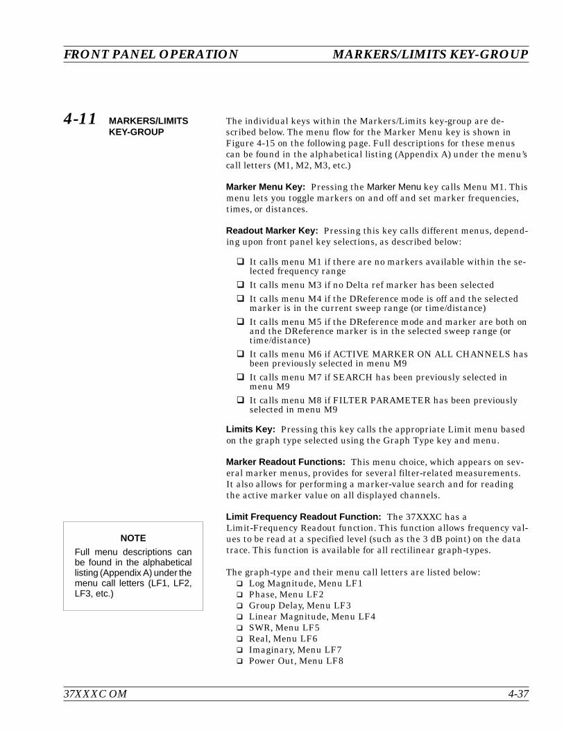
4-11 MARKERS/LIMITSKEY-GROUP
The individual keys within the Markers/Limits key-group are de-scribed below. The menu flow for the Marker Menu key is shown inFigure 4-15 on the following page. Full descriptions for these menuscan be found in the alphabetical listing (Appendix A) under the menu’scall letters (M1, M2, M3, etc.)
Marker Menu Key: Pressing the Marker Menu key calls Menu M1. Thismenu lets you toggle markers on and off and set marker frequencies,times, or distances.
Readout Marker Key: Pressing this key calls different menus, depend-ing upon front panel key selections, as described below:
It calls menu M1 if there are no markers available within the se-lected frequency range
It calls menu M3 if no Delta ref marker has been selected It calls menu M4 if the DReference mode is off and the selected
marker is in the current sweep range (or time/distance) It calls menu M5 if the DReference mode and marker are both on
and the DReference marker is in the selected sweep range (ortime/distance)
It calls menu M6 if ACTIVE MARKER ON ALL CHANNELS hasbeen previously selected in menu M9
It calls menu M7 if SEARCH has been previously selected inmenu M9
It calls menu M8 if FILTER PARAMETER has been previouslyselected in menu M9
Limits Key: Pressing this key calls the appropriate Limit menu basedon the graph type selected using the Graph Type key and menu.
Marker Readout Functions: This menu choice, which appears on sev-eral marker menus, provides for several filter-related measurements.It also allows for performing a marker-value search and for readingthe active marker value on all displayed channels.
Limit Frequency Readout Function: The 37XXXC has aLimit-Frequency Readout function. This function allows frequency val-ues to be read at a specified level (such as the 3 dB point) on the datatrace. This function is available for all rectilinear graph-types.
The graph-type and their menu call letters are listed below: Log Magnitude, Menu LF1 Phase, Menu LF2 Group Delay, Menu LF3 Linear Magnitude, Menu LF4 SWR, Menu LF5 Real, Menu LF6 Imaginary, Menu LF7 Power Out, Menu LF8
37XXXC OM 4-37
FRONT PANEL OPERATION MARKERS/LIMITS KEY-GROUP
NOTE
Full menu descriptions canbe found in the alphabeticallisting (Appendix A) under themenu call letters (LF1, LF2,LF3, etc.)
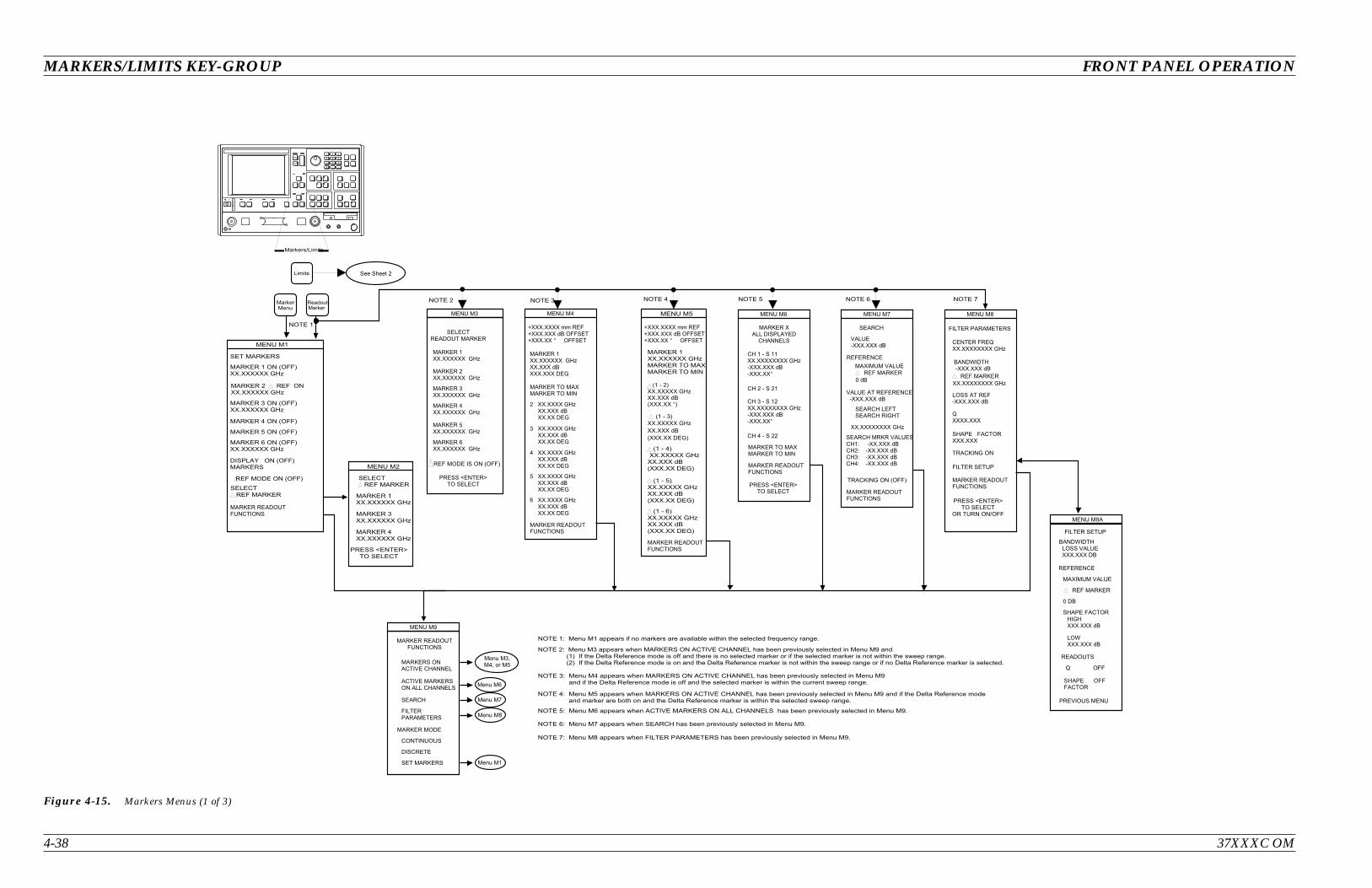
4-38 37XXXC OM
MARKERS/LIMITS KEY-GROUP FRONT PANEL OPERATION
! " ! # $ % & % ' ( ) * $ + ! $ * # , % * * % $ ! # $ % , - * $ ! # $ % , - $ $ $ . / ' ) * $ + ! $ * # , % % $ + ! $ * # , - $ $ $ . * + ! $ * # , - ! # $ % /
! " ! # $ % & % * $ + ! $ * # , % * * % $ ! # $ % , - $ $ # $ . /
0 ! " ! # $ % & % * $ + ! $ * # , % % , - $ % $ + ! $ * # , - $ $ ! # $ % . /
$
( ( * , - ! ! $ $ ! # $ % * 1 # " . /
2
(3 3 / 3 3 3 3 3 3 4 5
3 3 / 3 3 3 3 3 3 4 5
3 3 / 3 3 3 3 3 3 4 5
6 7 8
9
2 (
' 9 9 )
0 ' 9 9 )
9 + ' 9 9 )
( ' 9 9 )3 3 / 3 3 3 3 3 3 4 5
9 3 3 / 3 3 3 3 3 3 4 5
' 9 9 )3 3 / 3 3 3 3 3 3 4 5
: ' 9 9 )3 3 / 3 3 3 3 3 3 4 5
+ 6 ; ' 9 9 )
9
- < , $
, $
-
% $ -
2 0
( 3 3 / 3 3 3 3 3 3 4 5 3
' ( = ) 3 3 / 3 3 3 3 3 4 53 3 / 3 3 3 % >' 3 3 3 / 3 3 + 4 )
' ( = 0 )3 3 / 3 3 3 3 3 4 53 3 / 3 3 3 % >' 3 3 3 / 3 3 + 4 )
' ( = : )3 3 / 3 3 3 3 3 4 53 3 / 3 3 3 % >' 3 3 3 / 3 3 + 4 )
' ( = )3 3 / 3 3 3 3 3 4 53 3 / 3 3 3 % >' 3 3 3 / 3 3 ? )
+ 2 9 2
' ( = )
3 3 / 3 3 3 3 3 4 5
3 3 / 3 3 3 % >
' 3 3 3 / 3 3 + 4 )
+ 2 9 2
0 : ! " ! # $ % & /
: @ ! " ! # $ % & /
@ A 9 6 ! " ! # $ % & /
0 : @
2 2
(3 3 / 3 3 3 3 3 3 4 53 3 / 3 3 3 % >3 3 3 / 3 3 3 + 4
3
3 3 / 3 3 3 3 4 5 3 3 / 3 3 3 % > 3 3 / 3 3 + 4
3 3 / 3 3 3 3 4 5 3 3 / 3 3 3 % > 3 3 / 3 3 + 4
3 3 / 3 3 3 3 4 5 3 3 / 3 3 3 % > 3 3 / 3 3 + 4
0 3 3 / 3 3 3 3 4 5 3 3 / 3 3 3 % > 3 3 / 3 3 + 4
: 3 3 / 3 3 3 3 4 5 3 3 / 3 3 3 % > 3 3 / 3 3 + 4
+ 2 9 2
+ 2
(3 3 / 3 3 3 3 3 3 4 5
3 3 / 3 3 3 3 3 3 4 5
03 3 / 3 3 3 3 3 3 4 5
9 + ' 9 9 )
6 7 8
3 3 / 3 3 3 3 3 3 4 5
3 3 / 3 3 3 3 3 3 4 5
:3 3 / 3 3 3 3 3 3 4 5
2 &
+ 2 9 2
9 6
+
2 2
+
B B 0
@
A
(
2 :
+ 2 9 2
3 + 6 ; +
( = ( (3 3 / 3 3 3 3 3 3 3 3 4 5= 3 3 3 / 3 3 3 % >= 3 3 3 / 3 3 ?
= (
= ( 3 3 / 3 3 3 3 3 3 3 3 4 5= 3 3 3 / 3 3 3 % >= 3 3 3 / 3 3 ?
=
3
2 @
4 ' 9 9 )
2 = 3 3 3 / 3 3 3 % >
9
3 2 2
2 9 = 3 3 3 / 3 3 3 % >
3 3 / 3 3 3 3 3 3 3 3 4 5
+ 2 9 2
C % >
9
6 7 8
2 A
D 3 3 3 3 / 3 3 3
6 9 3 3 3 / 3 3 3
9 6
9 D3 3 / 3 3 3 3 3 3 3 3 4 5
9= 3 3 3 / 3 3 3 % >
4
9 2 6
+ 2 9 2
> + E + = 3 3 3 / 3 3 3 % >
9
3 3 / 3 3 3 3 3 3 3 3 4 5
6 7 8
2 < 9 9 2 A
9 2 6
> + E + 2 3 3 3 / 3 3 3 + >
9
3 2 2
C + >
6 9 4 3 3 3 / 3 3 3 % >
E3 3 3 / 3 3 3 % >
+ 2
D 9 9
6 9 99
6 2 2
9
:
9 4
2 ( = 3 3 / 3 3 3 % > = 3 3 / 3 3 3 % > = 3 3 / 3 3 3 % > = 3 3 / 3 3 3 % >
(
@ A &
0 :
(
C / =
F 3 3 3 / 3 3 3 3 , , 9F 3 3 3 / 3 3 3 % > 9 9 F 3 3 3 / 3 3 ? 9 9
F 3 3 3 / 3 3 3 3 , , 9F 3 3 3 / 3 3 3 % > 9 9 F 3 3 3 / 3 3 ? 9 9
Figure 4-15. Markers Menus (1 of 3)
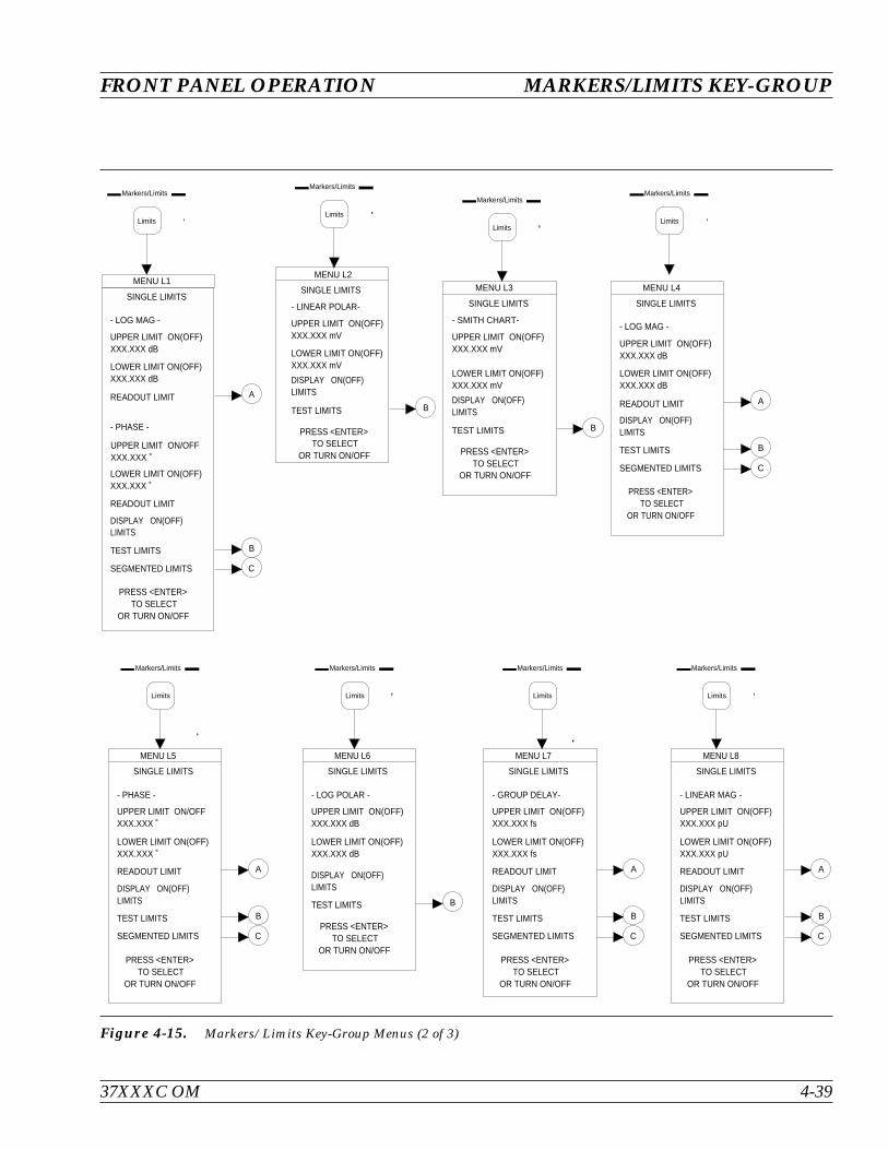
37XXXC OM 4-39
FRONT PANEL OPERATION MARKERS/LIMITS KEY-GROUP
Markers/Limits
Limits
MENU L3
PRESS <ENTER>TO SELECT
OR TURN ON/OFF
SINGLE LIMITS
- SMITH CHART-
UPPER LIMIT ON(OFF)XXX.XXX mV
LOWER LIMIT ON(OFF) XXX.XXX mV
DISPLAY ON(OFF)LIMITS
TEST LIMITS B
MENU L6
PRESS <ENTER>TO SELECT
OR TURN ON/OFF
SINGLE LIMITS
- LOG POLAR -
UPPER LIMIT ON(OFF)XXX.XXX dB
LOWER LIMIT ON(OFF) XXX.XXX dB
DISPLAY ON(OFF)LIMITS
TEST LIMITS B
Markers/Limits
Limits
Markers/Limits
Limits
MENU L2
PRESS <ENTER>TO SELECT
OR TURN ON/OFF
SINGLE LIMITS
- LINEAR POLAR-
UPPER LIMIT ON(OFF)XXX.XXX mV
LOWER LIMIT ON(OFF) XXX.XXX mV
DISPLAY ON(OFF)LIMITS
TEST LIMITS B
Markers/Limits
Limits
MENU L4
PRESS <ENTER>TO SELECT
OR TURN ON/OFF
SINGLE LIMITS
- LOG MAG -
UPPER LIMIT ON(OFF)XXX.XXX dB
LOWER LIMIT ON(OFF) XXX.XXX dB
READOUT LIMIT
DISPLAY ON(OFF)LIMITS
TEST LIMITS
SEGMENTED LIMITS
A
B
C
Markers/Limits
Limits
MENU L7
PRESS <ENTER>TO SELECT
OR TURN ON/OFF
SINGLE LIMITS
- GROUP DELAY-
UPPER LIMIT ON(OFF)XXX.XXX fs
LOWER LIMIT ON(OFF) XXX.XXX fs
READOUT LIMIT
DISPLAY ON(OFF)LIMITS
TEST LIMITS
SEGMENTED LIMITS
A
B
C
Markers/Limits
Limits
MENU L1
PRESS <ENTER>TO SELECT
OR TURN ON/OFF
SINGLE LIMITS
- LOG MAG -
UPPER LIMIT ON(OFF)XXX.XXX dB
LOWER LIMIT ON(OFF) XXX.XXX dB
READOUT LIMIT
- PHASE -
UPPER LIMIT ON/OFFXXX.XXX ˚
LOWER LIMIT ON(OFF)XXX.XXX ˚
READOUT LIMIT
DISPLAY ON(OFF)LIMITS
TEST LIMITS
SEGMENTED LIMITS
A
B
C
MENU L5
PRESS <ENTER>TO SELECT
OR TURN ON/OFF
SINGLE LIMITS
- PHASE -
UPPER LIMIT ON/OFFXXX.XXX ˚
LOWER LIMIT ON(OFF)XXX.XXX ˚
READOUT LIMIT
DISPLAY ON(OFF)LIMITS
TEST LIMITS
SEGMENTED LIMITS
A
B
C
Markers/Limits
Limits
Markers/Limits
Limits
MENU L8
PRESS <ENTER>TO SELECT
OR TURN ON/OFF
SINGLE LIMITS
- LINEAR MAG -
UPPER LIMIT ON(OFF)XXX.XXX pU
LOWER LIMIT ON(OFF) XXX.XXX pU
READOUT LIMIT
DISPLAY ON(OFF)LIMITS
TEST LIMITS
SEGMENTED LIMITS
A
B
C
Figure 4-15. Markers/Limits Key-Group Menus (2 of 3)

MARKERS/LIMITS KEY-GROUP FRONT PANEL OPERATION
4-40 37XXXC OM
MENU L13
PRESS <ENTER>TO SELECT
OR TURN ON/OFF
SINGLE LIMITS
- SWR-
READOUT LIMIT
DISPLAY ON(OFF)LIMITS
TEST LIMITS
SEGMENTED LIMITS
A
B
C
UPPER LIMIT ON(OFF)XXX.XXX pU
LOWER LIMIT ON(OFF) XXX.XXX pU
UPPER LIMIT ON(OFF)XXX.XXX pU
LOWER LIMIT ON(OFF) XXX.XXX pU
MENU L12
PRESS <ENTER>TO SELECT
OR TURN ON/OFF
SINGLE LIMITS
- REAL -
READOUT LIMIT
- IMAGINARY -
READOUT LIMIT
DISPLAY ON(OFF)LIMITS
TEST LIMITS
SEGMENTED LIMITS
A
B
C
LOWER LIMIT ON(OFF) XXX.XXX pU
UPPER LIMIT ON(OFF)XXX.XXX pU
A
Markers/Limits
Limits
Markers/Limits
Limits
MENU L9
PRESS <ENTER>TO SELECT
OR TURN ON/OFF
SINGLE LIMITS
- LINEAR MAG -
UPPER LIMIT ON(OFF)XXX.XXX dB
LOWER LIMIT ON(OFF) XXX.XXX dB
READOUT LIMIT
- PHASE -
UPPER LIMIT ON/OFFXXX.XXX ˚
LOWER LIMIT ON(OFF)XXX.XXX ˚
READOUT LIMIT
DISPLAY ON(OFF)LIMITS
TEST LIMITS
SEGMENTED LIMITS
B
C
A
Markers/Limits
Limits
A
B
MENU L11
PRESS <ENTER>TO SELECT
OR TURN ON/OFF
SINGLE LIMITS
- IMAGINARY-
UPPER LIMIT ON(OFF)XXX.XXX pU
LOWER LIMIT ON(OFF) XXX.XXX pU
READOUT LIMIT
DISPLAY ON(OFF)LIMITS
TEST LIMITS
SEGMENTED LIMITS
A
B
C
Markers/Limits
Limits
MENU LTST
TEST LIMITS
LIMIT ON (OFF)TESTING
PRESS <ENTER>TO SELECT
OR TURN ON/OFF
BEEP FOR ON (OFF)TEST FAILURE
LIMIT TEST TTLFAIL CONDITION
TTL LOW/TTL HIGH
CHANNEL 1 TESTPASS (FAIL)
CHANNEL 2 TESTPASS (FAIL)
CHANNEL 3 TESTPASS (FAIL)
CHANNEL 4 TESTPASS (FAIL)
MENU LD1
PRESS <ENTER>TO SELECT
OR TURN ON/OFF
DEFINE UPPER SEGS
SEGMENT ON (OFF)X
START POSITIONHORIZONTALXXX.XXXXXXXXX GHz
STOP POSITION
VERTICALXX.XXX dB
HORIZONTALXXX.XXXXXXXXX GHz
VERTICALXX.XXX dB
BEGIN NEXTATTACH NEXTCLEAR SEGMENTPREVIOUS MENU
MENU LD1
PRESS <ENTER>TO SELECT
OR TURN ON/OFF
DEFINE LOWER SEGS
SEGMENT ON (OFF)X
START POSITIONHORIZONTALXXX.XXXXXXXXX GHz
STOP POSITION
VERTICALXX.XXX dB
HORIZONTALXXX.XXXXXXXXX GHz
VERTICALXX.XXX dB
BEGIN NEXTATTACH NEXT
CLEAR SEGMENTPREVIOUS MENU
C
MENU LSX
PRESS <ENTER>TO SELECT
OR TURN ON/OFF
SEGMENTED LIMITS
XXXXXXXXX
UPPER LIMIT ON(OFF)
DEFINE UPPER
LOWER LIMIT ON(OFF)
DEFINE LOWER
SEGMENTED OFFSETS
CLEAR ALL
DISPLAY ON(OFF)LIMITS
TEST LIMITS
SINGLE LIMITS
A
MENU LFX
READOUT LIMITINTERCEPTS
UPPER LIMIT (REF) XXX.XXX xx
LOWER LIMIT XXX.XXX xxL IMIT DIFFERENCE
(UPPER-LOWER)
INTERCEPTS AT LOWER LIMIT
X.XXXX GHzX.XXXX GHzX.XXXX GHzX.XXXX GHzX.XXXX GHzX.XXXX GHz
- XXXXXXX -
∆
HORIZONTALXXX.XXXXXXXXX GHz
VERTICALXX.XXX dB
B
C
MENU L10
PRESS <ENTER>TO SELECT
OR TURN ON/OFF
SINGLE LIMITS
- REAL -
UPPER LIMIT ON(OFF)XXX.XXX pU
LOWER LIMIT ON(OFF) XXX.XXX pU
READOUT LIMIT
DISPLAY ON(OFF)LIMITS
TEST LIMITS
SEGMENTED LIMITS
A
Markers/Limits
Limits
MENU L14
PRESS <ENTER>TO SELECT
OR TURN ON/OFF
SINGLE LIMITS
- POWER OUT--
READOUT LIMIT
DISPLAY ON(OFF)LIMITS
TEST LIMITS
A
B
UPPER LIMIT ON(OFF)XXX.XXX pU
LOWER LIMIT ON(OFF) XXX.XXX pU
Markers/Limits
Limits
Figure 4-15. Markers/Limits Key-Group Menus (3 of 3)
4-12 DISK STORAGEINTERFACE
The 37XXXC has two internally mounted disk drives: an 80 MB harddisk and a 3.5 inch floppy. The format, files, and directory are compati-ble with MS-DOS, Version 5.0 and above.
Disk Format Floppy diskettes are MS-DOS compatible and have a 1.44 MByte ca-pacity.
Disk Files You may find any of the following file-types on the 37XXXC disk:
Program Files: These are binary files used to load the operatingprogram. They are provided on the hard drive, and a backup copyis provided on floppy diskettes. Application programs cannotread them
Calibration Data Files: These are binary files used to store andretrieve calibration and other data. Application programs cannotread them. File size depends on calibration type
Text Files: These are tab-delimited ASCII files with the “txt” fileextension. They can be read by application programs
S2P Parameter Data Files: These files define a 2-port file formatthat includes all four S parameters. They can be read by applica-tions programs. They have a file extension of “S2P”
Tabular Measurement Data Files: These are ASCII files used tostore actual measurement data. They can be read by applicationsprograms. File size depends on selected options
Trace Memory Files: These are binary files used to store tracedata. Applications programs cannot read them. You use them toperform trace math operations on data
Cal Kit File for Coax or Waveguide
AutoCal Characterization file
37XXXC OM 4-41
FRONT PANEL OPERATION DISK STORAGE INTERFACE
NOTE
File names must begin withalphabetical, not numericcharacters.
Disk File Output Device You can select the output drive destination for the disk file as eitherthe hard disk (C:) or the floppy drive (A:). The format of the disk file isalso selected. The default condition is text disk file to the hard disk.
You may then proceed with normal measurements. The Start Print keymay then be used at the instant you intend to capture the data. MenuDISK 3 then appears and allows the creation of a new file or to over-write an existing file in the current directory.
Note that the output for text and S2P files have predefined formats.Tabular data format is configured via the Print Options (Menu PM5)or Tabular Data (Menu PM3). Bitmap format is configured via thePrint Options (Menu PM5), Options (Menu PM5, or Graphical Data(Menu PM3A). HPGL format is configured via the Plot Options (MenuPL1).
You are able to direct hard copy output to the HDD or floppy, in addi-tion to the printer and plotter. In addition to text (*.txt), S2P (*.s2p),and tabular (*.dat) files, bitmaps (*.bmp) and HPGL (*.hgl) files are of-fered to satisfy your desktop publishing requirements. Specifically,color bitmaps and graphic language files can be imported into Win-dows applications, such as Cap3700.
Formatting a Data File Disk You may format additional diskettes to hold calibration, tabular mea-surement, and trace-memory data files. Do this using the FORMATDISK selection on the “Floppy Disk Utilities” menu. Using this selec-tion will format the target disk and overwrite any existing data it con-tains.
A format hard disk utility is provided in case of hard disk failure.Using this feature overwrites your system software and requires boot-ing from the backup floppy diskettes.
Copying Data Files FromDisk to Disk
Use the COPY FILES selection on the “Floppy Disk Utilities” and“Hard Disk Utilities” menus to copy data files between hard and floppydiskettes.
Recovering From DiskWrite/Read Errors
If you experience a read or write error during a disk operation, youshould:
Verify first character of filename is alphabetical and not numeric
Verify that the diskette has been properly formatted
Verify that the diskette is high density (1.44 MB). Low density(720 KB) diskettes are not supported
Verify that the write-protect tab on the disk is engaged
Retry the disk operation
Repeated disk errors may indicate a defective diskette and format.
DISK STORAGE INTERFACE FRONT PANEL OPERATION
4-42 37XXXC OM
4-13 COMMAND LINE The Command Line menu choice provides several DOS compatiblecommands. Command line options are:
CREATE DIRECTORY (MD)
LIST DIRECTORY (DIR)
CHANGE DIRECTORY (CD)
DELETE FILES (DEL)
REMOVE DIRECTORY (RD)
COPY FILES (COPY)
These options are NOT case sensitive.
Create Directory This command is performed by: MD c:\pat-h\dir_name orMD a:\path\dir_name. The c: is used to refer to the hard disk, and a:is for the floppy disk.
List Directory This command is performed by “DIR” command. This may be used asDIR c:\path or without any path specified. The syntax is:
DIR c:\path or DIR a:\path.
If c: or a: is not used, the default is the current hard disk directory. Youmay use wild cards as follows:
DIR *.cal
DIR filter?.cal
Change Directory This command is performed by CD c:\path or CD a:\path. Both ofthese options do not require a device name. The device name is re-ferred to by c: or a:.
If you choose to do CD dir_name, this implies the current Hard disk di-rectory.
Delete Files This command is used to delete a particular file(s) in a directory, or de-lete the entire contents of the directory by using the wild card option.The command line is:
DEL filename
DEL c:\path\filename
DEL a:\path\*
37XXXC OM 4-43
FRONT PANEL OPERATION COMMAND LINE
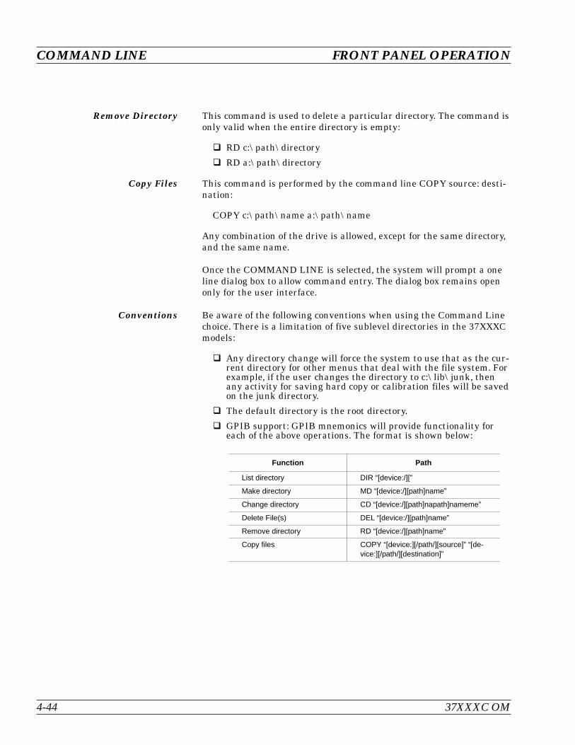
Remove Directory This command is used to delete a particular directory. The command isonly valid when the entire directory is empty:
RD c:\path\directory
RD a:\path\directory
Copy Files This command is performed by the command line COPY source: desti-nation:
COPY c:\path\name a:\path\name
Any combination of the drive is allowed, except for the same directory,and the same name.
Once the COMMAND LINE is selected, the system will prompt a oneline dialog box to allow command entry. The dialog box remains openonly for the user interface.
Conventions Be aware of the following conventions when using the Command Linechoice. There is a limitation of five sublevel directories in the 37XXXCmodels:
Any directory change will force the system to use that as the cur-rent directory for other menus that deal with the file system. Forexample, if the user changes the directory to c:\lib\junk, thenany activity for saving hard copy or calibration files will be savedon the junk directory.
The default directory is the root directory.
GPIB support: GPIB mnemonics will provide functionality foreach of the above operations. The format is shown below:
Function Path
List directory DIR “[device:/][”
Make directory MD “[device:/][path]name”
Change directory CD “[device:/][path]napath]nameme”
Delete File(s) DEL “[device:/][path]name”
Remove directory RD “[device:/][path]name”
Copy files COPY “[device:][/path/][source]” “[de-vice:][/path/][destination]”
COMMAND LINE FRONT PANEL OPERATION
4-44 37XXXC OM
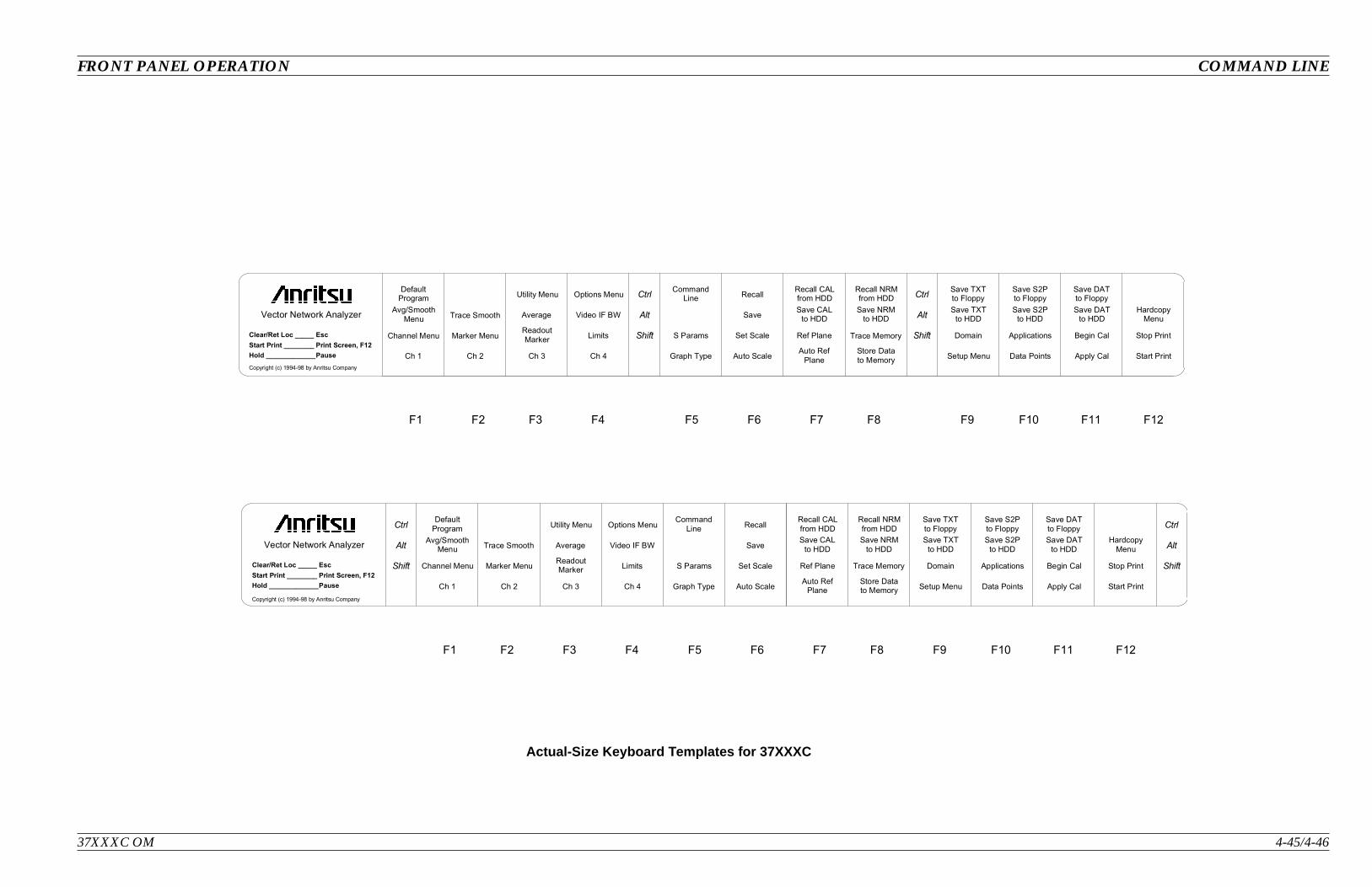
FRONT PANEL OPERATION COMMAND LINE
37XXXC OM 4-45/4-46
F2 F3 F4F1 F5 F6 F7 F8 F9 F10 F11 F12
Ctrl
Alt
Shift
Ctrl
Alt
Shift
Ch 1 Ch 2 Ch 3 Ch 4 Graph Type Auto ScaleAuto Ref
PlaneStore Datato Memory
Channel Menu Marker MenuReadoutMarker
Limits S Params Set Scale Ref Plane Trace Memory
Avg/SmoothMenu
Trace Smooth Average Video IF BW SaveSave CAL
to HDDSave NRM
to HDD
DefaultProgram
Utility Menu Options MenuRecall CALfrom HDD
Recall NRMfrom HDD
Setup Menu Data Points Apply Cal Start Print
Stop PrintBegin CalApplicationsDomain
Save TXTto HDD
Save S2Pto HDD
Save DATto HDD
HardcopyMenu
CommandLine
Start Print ________
Hold _____________
Print Screen, F12
Pause
Copyright (c) 1994-98 by Anritsu Company
Save TXTto Floppy
Save S2Pto Floppy
Save DATto Floppy
Recall
Vector Network Analyzer
Clear/Ret Loc _____ Esc
Ctrl
Alt
Shift
Ctrl
Alt
Shift
F2 F3 F4F1 F5 F6 F7 F8 F9 F10 F11 F12
Clear/Ret Loc _____
Start Print ________
Hold _____________
Esc
Print Screen, F12
Pause Ch 1 Ch 2 Ch 3 Ch 4 Graph Type Auto ScaleAuto Ref
PlaneStore Datato Memory
Channel Menu Marker MenuReadoutMarker
Limits S Params Set Scale Ref Plane Trace Memory
Avg/SmoothMenu
Trace Smooth Average Video IF BWSave CAL
to HDDSave NRM
to HDD
DefaultProgram
Utility Menu Options MenuRecall CALfrom HDD
Recall NRMfrom HDD
Setup Menu Data Points Apply Cal Start Print
Stop PrintBegin CalApplicationsDomain
Save TXTto HDD
Save S2Pto HDD
Save DATto HDD
HardcopyMenu
CommandLine
Save TXTto Floppy
Save S2Pto Floppy
Save DATto Floppy
Save
Recall
Vector Network Analyzer
Copyright (c) 1994-98 by Anritsu Company
Actual-Size Keyboard Templates for 37XXXC

Table of Contents
5-1 INTRODUCTION . . . . . . . . . . . . . . . . . . . . . . . . . . . . . . . . . . . 5-3
5-2 ERROR MESSAGES. . . . . . . . . . . . . . . . . . . . . . . . . . . . . . . . . . 5-3
Chapter 5Error and Status


Chapter 5Error and Status Messages
5-1 INTRODUCTION This chapter lists, describes, and provides corrective action for the er-ror messages that point to problems that the operator can correct. Anyerror messages that appear on the display but do not appear in thischapter will require action by a qualified service representative.
5-2 ERROR MESSAGES Error messages are provided in Tables 5-1 and 5-2.
37XXXC OM 5-3
Error Message Description Corrective Action
ATTENUATOR UNAVAILABLE Option 6 Port 2 Test Step Attenuator isnot installed.
Install Option 6 Step Attenuator,
BANDS MUST SEQUENCE Frequency bands in Multiple Sourcemode must sequence in a 1-2-3-4-5 or-der.
None, no skipping is allowed.
BOTH LIMITS MUST BE ON Must have both limits activated. Turn on limits.
DIFFERENT H/W SETUP. RECALLABORTED
Source is different from the recalledsetup.
Reconfigure system to duplicate thehardware setup that was used to storethe saved data.
DIFFERENT S/W VERSION, RECALLABORTED
Saved state not compatible with hard-ware or software version.
Load compatible software (S/W) versionand retry.
DISCRETE FREQS LOST Change in frequency caused discrete fillfrequencies to be lost.
None.
DISPERSIVE MEDIUM, ONLY TIMEUSED
Distance does not apply for dispersivemedia.
None.
FREQUENCIES HAVE REACHED UPPERLIMIT
Frequencies being defined in MultipleSource mode have reached upper limitsof Sources.
Redefine frequencies to not exceed lim-its of Sources.
ILLEGAL IN C.W. MODE Attempted to readout limit frequency. None, no limit lines are permitted in CWmode.
ILLEGAL IN TIME DOMAIN Attempted to readout limit frequency None.
LOGO FILE NOT FOUND Attempted to read a non-existent logofile from disk.
Create user-defined logo using applica-tion on external controller.
MEAS DATA NOT AVAILABLE FORSTORAGE
Measurement data is not available forstorage on floppy or hard disk.
None.
MEMORY LOCATION CORRUPTED Requested memory location is cor-rupted.
None. If problem reoccurs after storing anew setup, contact Anritsu CustomerService.
NO BANDS ARE STORED No frequency bands have been definedand stored.
Need to define and store frequencybands to turn on Multiple Source mode.
Table 5-1. General Error Messages (1 of 3)
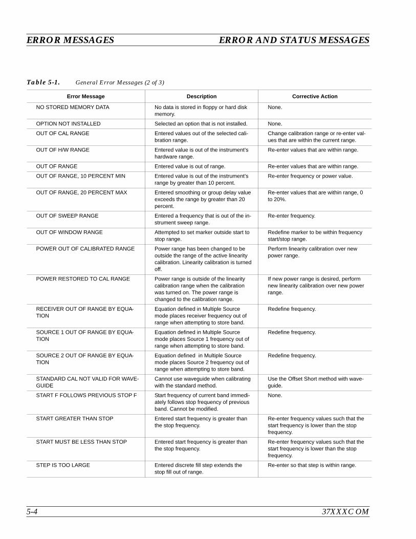
ERROR MESSAGES ERROR AND STATUS MESSAGES
5-4 37XXXC OM
Error Message Description Corrective Action
NO STORED MEMORY DATA No data is stored in floppy or hard diskmemory.
None.
OPTION NOT INSTALLED Selected an option that is not installed. None.
OUT OF CAL RANGE Entered values out of the selected cali-bration range.
Change calibration range or re-enter val-ues that are within the current range.
OUT OF H/W RANGE Entered value is out of the instrument’shardware range.
Re-enter values that are within range.
OUT OF RANGE Entered value is out of range. Re-enter values that are within range.
OUT OF RANGE, 10 PERCENT MIN Entered value is out of the instrument’srange by greater than 10 percent.
Re-enter frequency or power value.
OUT OF RANGE, 20 PERCENT MAX Entered smoothing or group delay valueexceeds the range by greater than 20percent.
Re-enter values that are within range, 0to 20%.
OUT OF SWEEP RANGE Entered a frequency that is out of the in-strument sweep range.
Re-enter frequency.
OUT OF WINDOW RANGE Attempted to set marker outside start tostop range.
Redefine marker to be within frequencystart/stop range.
POWER OUT OF CALIBRATED RANGE Power range has been changed to beoutside the range of the active linearitycalibration. Linearity calibration is turnedoff.
Perform linearity calibration over newpower range.
POWER RESTORED TO CAL RANGE Power range is outside of the linearitycalibration range when the calibrationwas turned on. The power range ischanged to the calibration range.
If new power range is desired, performnew linearity calibration over new powerrange.
RECEIVER OUT OF RANGE BY EQUA-TION
Equation defined in Multiple Sourcemode places receiver frequency out ofrange when attempting to store band.
Redefine frequency.
SOURCE 1 OUT OF RANGE BY EQUA-TION
Equation defined in Multiple Sourcemode places Source 1 frequency out ofrange when attempting to store band.
Redefine frequency.
SOURCE 2 OUT OF RANGE BY EQUA-TION
Equation defined in Multiple Sourcemode places Source 2 frequency out ofrange when attempting to store band.
Redefine frequency.
STANDARD CAL NOT VALID FOR WAVE-GUIDE
Cannot use waveguide when calibratingwith the standard method.
Use the Offset Short method with wave-guide.
START F FOLLOWS PREVIOUS STOP F Start frequency of current band immedi-ately follows stop frequency of previousband. Cannot be modified.
None.
START GREATER THAN STOP Entered start frequency is greater thanthe stop frequency.
Re-enter frequency values such that thestart frequency is lower than the stopfrequency.
START MUST BE LESS THAN STOP Entered start frequency is greater thanthe stop frequency.
Re-enter frequency values such that thestart frequency is lower than the stopfrequency.
STEP IS TOO LARGE Entered discrete fill step extends thestop fill out of range.
Re-enter so that step is within range.
Table 5-1. General Error Messages (2 of 3)
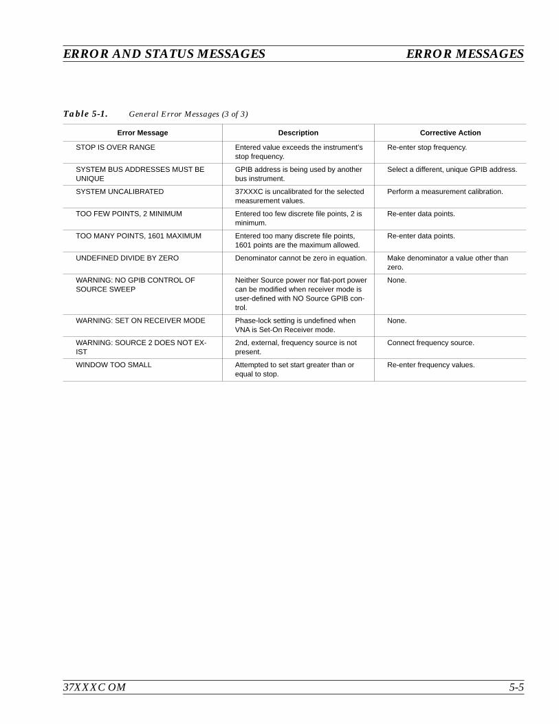
37XXXC OM 5-5
ERROR AND STATUS MESSAGES ERROR MESSAGES
Error Message Description Corrective Action
STOP IS OVER RANGE Entered value exceeds the instrument’sstop frequency.
Re-enter stop frequency.
SYSTEM BUS ADDRESSES MUST BEUNIQUE
GPIB address is being used by anotherbus instrument.
Select a different, unique GPIB address.
SYSTEM UNCALIBRATED 37XXXC is uncalibrated for the selectedmeasurement values.
Perform a measurement calibration.
TOO FEW POINTS, 2 MINIMUM Entered too few discrete file points, 2 isminimum.
Re-enter data points.
TOO MANY POINTS, 1601 MAXIMUM Entered too many discrete file points,1601 points are the maximum allowed.
Re-enter data points.
UNDEFINED DIVIDE BY ZERO Denominator cannot be zero in equation. Make denominator a value other thanzero.
WARNING: NO GPIB CONTROL OFSOURCE SWEEP
Neither Source power nor flat-port powercan be modified when receiver mode isuser-defined with NO Source GPIB con-trol.
None.
WARNING: SET ON RECEIVER MODE Phase-lock setting is undefined whenVNA is Set-On Receiver mode.
None.
WARNING: SOURCE 2 DOES NOT EX-IST
2nd, external, frequency source is notpresent.
Connect frequency source.
WINDOW TOO SMALL Attempted to set start greater than orequal to stop.
Re-enter frequency values.
Table 5-1. General Error Messages (3 of 3)
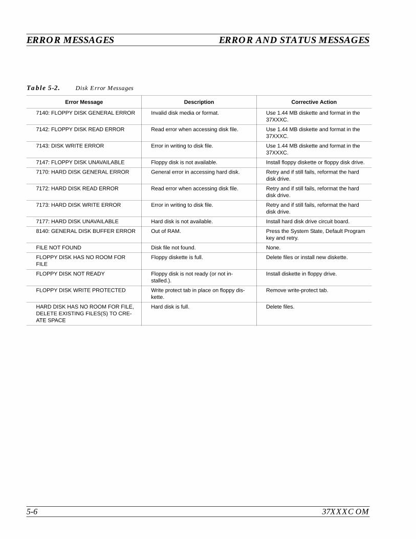
ERROR MESSAGES ERROR AND STATUS MESSAGES
5-6 37XXXC OM
Error Message Description Corrective Action
7140: FLOPPY DISK GENERAL ERROR Invalid disk media or format. Use 1.44 MB diskette and format in the37XXXC.
7142: FLOPPY DISK READ ERROR Read error when accessing disk file. Use 1.44 MB diskette and format in the37XXXC.
7143: DISK WRITE ERROR Error in writing to disk file. Use 1.44 MB diskette and format in the37XXXC.
7147: FLOPPY DISK UNAVAILABLE Floppy disk is not available. Install floppy diskette or floppy disk drive.
7170: HARD DISK GENERAL ERROR General error in accessing hard disk. Retry and if still fails, reformat the harddisk drive.
7172: HARD DISK READ ERROR Read error when accessing disk file. Retry and if still fails, reformat the harddisk drive.
7173: HARD DISK WRITE ERROR Error in writing to disk file. Retry and if still fails, reformat the harddisk drive.
7177: HARD DISK UNAVAILABLE Hard disk is not available. Install hard disk drive circuit board.
8140: GENERAL DISK BUFFER ERROR Out of RAM. Press the System State, Default Programkey and retry.
FILE NOT FOUND Disk file not found. None.
FLOPPY DISK HAS NO ROOM FORFILE
Floppy diskette is full. Delete files or install new diskette.
FLOPPY DISK NOT READY Floppy disk is not ready (or not in-stalled.).
Install diskette in floppy drive.
FLOPPY DISK WRITE PROTECTED Write protect tab in place on floppy dis-kette.
Remove write-protect tab.
HARD DISK HAS NO ROOM FOR FILE,DELETE EXISTING FILES(S) TO CRE-ATE SPACE
Hard disk is full. Delete files.
Table 5-2. Disk Error Messages
Table of Contents
6-1 INTRODUCTION . . . . . . . . . . . . . . . . . . . . . . . . . . . . . . . . . . . 6-3
6-2 DISPLAY MODES AND TYPES . . . . . . . . . . . . . . . . . . . . . . . . . . . 6-3
Single Channel Display: Ch 1, 2, 3, 4. . . . . . . . . . . . . . . . . . . . . . . . 6-3
Dual Channel Display: Ch 1 and 3 or Ch 2 and 4 . . . . . . . . . . . . . . . . . 6-4
Four Channel Display: Ch 1, 2, 3, 4 . . . . . . . . . . . . . . . . . . . . . . . . 6-5
Dual Trace Overlay . . . . . . . . . . . . . . . . . . . . . . . . . . . . . . . . . 6-6
Graph Data Types. . . . . . . . . . . . . . . . . . . . . . . . . . . . . . . . . . 6-7
6-3 FREQUENCY MARKERS . . . . . . . . . . . . . . . . . . . . . . . . . . . . . . 6-11
Marker Designation . . . . . . . . . . . . . . . . . . . . . . . . . . . . . . . . 6-11
6-4 LIMITS . . . . . . . . . . . . . . . . . . . . . . . . . . . . . . . . . . . . . . . . 6-11
6-5 STATUS DISPLAY . . . . . . . . . . . . . . . . . . . . . . . . . . . . . . . . . . 6-12
Reference Position Marker . . . . . . . . . . . . . . . . . . . . . . . . . . . . 6-12
Scale Resolution . . . . . . . . . . . . . . . . . . . . . . . . . . . . . . . . . . 6-12
Frequency Range . . . . . . . . . . . . . . . . . . . . . . . . . . . . . . . . . 6-12
Analog Instrument Status. . . . . . . . . . . . . . . . . . . . . . . . . . . . . 6-12
Measurement Status . . . . . . . . . . . . . . . . . . . . . . . . . . . . . . . 6-13
Sweep Indicator Marker . . . . . . . . . . . . . . . . . . . . . . . . . . . . . . 6-13
6-6 DATA DISPLAY CONTROL . . . . . . . . . . . . . . . . . . . . . . . . . . . . . 6-13
S-Parameter Selection . . . . . . . . . . . . . . . . . . . . . . . . . . . . . . . 6-14
Data Display Update . . . . . . . . . . . . . . . . . . . . . . . . . . . . . . . 6-14
Display of Markers. . . . . . . . . . . . . . . . . . . . . . . . . . . . . . . . . 6-14
6-7 HARD COPY AND DISK OUTPUT . . . . . . . . . . . . . . . . . . . . . . . . . 6-15
Tabular Printout . . . . . . . . . . . . . . . . . . . . . . . . . . . . . . . . . . 6-15
Screen-Image Printout . . . . . . . . . . . . . . . . . . . . . . . . . . . . . . 6-15
Plotter Output . . . . . . . . . . . . . . . . . . . . . . . . . . . . . . . . . . . 6-15
Disk Output . . . . . . . . . . . . . . . . . . . . . . . . . . . . . . . . . . . . 6-15
Chapter 6Data Displays

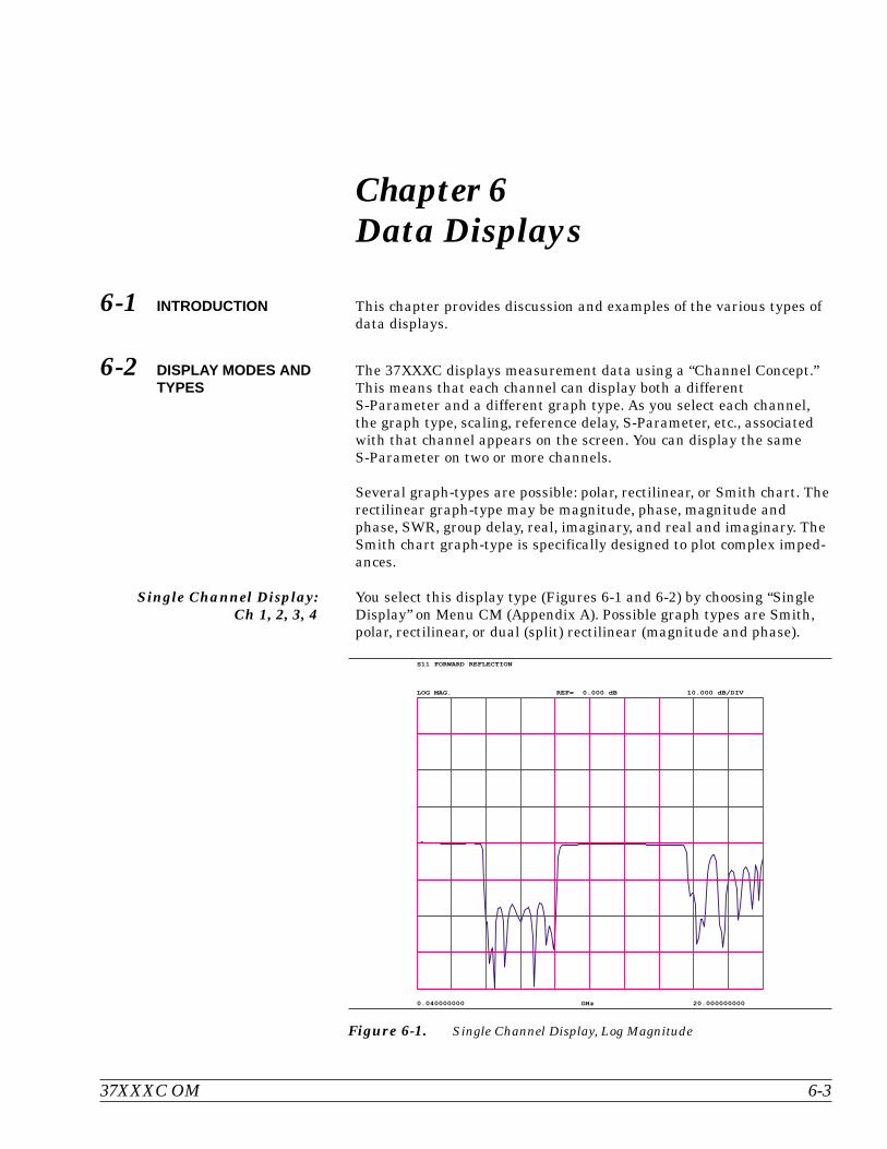
Chapter 6Data Displays
6-1 INTRODUCTION This chapter provides discussion and examples of the various types ofdata displays.
6-2 DISPLAY MODES ANDTYPES
The 37XXXC displays measurement data using a “Channel Concept.”This means that each channel can display both a differentS-Parameter and a different graph type. As you select each channel,the graph type, scaling, reference delay, S-Parameter, etc., associatedwith that channel appears on the screen. You can display the sameS-Parameter on two or more channels.
Several graph-types are possible: polar, rectilinear, or Smith chart. Therectilinear graph-type may be magnitude, phase, magnitude andphase, SWR, group delay, real, imaginary, and real and imaginary. TheSmith chart graph-type is specifically designed to plot complex imped-ances.
Single Channel Display:Ch 1, 2, 3, 4
You select this display type (Figures 6-1 and 6-2) by choosing “SingleDisplay” on Menu CM (Appendix A). Possible graph types are Smith,polar, rectilinear, or dual (split) rectilinear (magnitude and phase).
37XXXC OM 6-3
GHz0.040000000 20.000000000
S11 FORWARD REFLECTION
LOG MAG. REF= 0.000 dB 10.000 dB/DIV
Figure 6-1. Single Channel Display, Log Magnitude

Dual Channel Display:Ch 1 and 3 or Ch 2 and 4
If you have chosen a dual display of magnitude and phase, the affectedarea of the LCD screen is subdivided into two smaller portions (Figure6-3). You select this display type by choosing “Dual Display” in MenuCM (Appendix A).
DISPLAY MODES AND TYPES DATA DISPLAYS
6-4 37XXXC OM
GHz0.040000000 20.000000000
S11 FORWARD REFLECTION
LOG MAG.
PHASE
REF= 0.000 dB
REF= 0.00|
10.000 dB/DIV
90.00| /DIV
Figure 6-2. Single Channel Display, Magnitude and Phase
0
.2
-.2
.5
-.5
1
2
-2
5
-5
2.036000000 - 5.030000000 GHz
S11 FORWARD REFLECTION
IMPEDANCE
GHz2.036000000 5.030000000
S12 REVERSE TRANSMISSION
PHASE REF= 0.00| 90.00| /DIV
Figure 6-3. Dual Channel Display
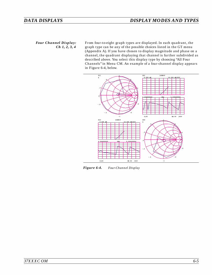
Four Channel Display:Ch 1, 2, 3, 4
From four-to-eight graph types are displayed. In each quadrant, thegraph type can be any of the possible choices listed in the GT menu(Appendix A). If you have chosen to display magnitude and phase on achannel, the quadrant displaying that channel is further subdivided asdescribed above. You select this display type by choosing “All FourChannels” in Menu CM. An example of a four-channel display appearsin Figure 6-4, below.
37XXXC OM 6-5
DATA DISPLAYS DISPLAY MODES AND TYPES
0
.2
-.2
.5
-.5
1
-1
2
-2
5
-5
S11
Z
GHz2.036000000 5.030000000
S21 LOGM+P
0.000 dB
0.00|
10.000 dB/DIV
90.00| /DIV
GHz2.036000000 5.030000000
S12 LOGM+P
0.000 dB
0.00|
10.000 dB/DIV
90.00| /DIV
0
.2
-.2
.5
-.5
1
-1
2
-2
5
-5
S22
Z
Figure 6-4. Four-Channel Display
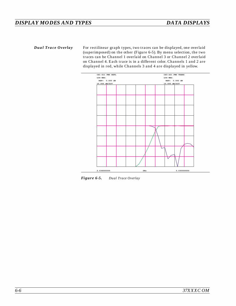
Dual Trace Overlay For rectilinear graph types, two traces can be displayed, one overlaid(superimposed) on the other (Figure 6-5). By menu selection, the twotraces can be Channel 1 overlaid on Channel 3 or Channel 2 overlaidon Channel 4. Each trace is in a different color. Channels 1 and 2 aredisplayed in red, while Channels 3 and 4 are displayed in yellow.
DISPLAY MODES AND TYPES DATA DISPLAYS
6-6 37XXXC OM
CH1:S11 FWD REFL
LOG MAG.
REF= 0.000 dB
10.000 dB/DIV
CH3:S21 FWD TRANS
LOG MAG.
REF= 0.000 dB
10.000 dB/DIV
GHz2.036000000 5.030000000
Figure 6-5. Dual Trace Overlay
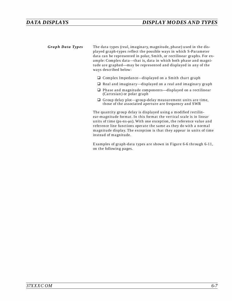
Graph Data Types The data types (real, imaginary, magnitude, phase) used in the dis-played graph-types reflect the possible ways in which S-Parameterdata can be represented in polar, Smith, or rectilinear graphs. For ex-ample: Complex data—that is, data in which both phase and magni-tude are graphed—may be represented and displayed in any of theways described below:
Complex Impedance—displayed on a Smith chart graph
Real and imaginary—displayed on a real and imaginary graph
Phase and magnitude components—displayed on a rectilinear(Cartesian) or polar graph
Group delay plot—group-delay measurement units are time,those of the associated aperture are frequency and SWR
The quantity group delay is displayed using a modified rectilin-ear-magnitude format. In this format the vertical scale is in linearunits of time (ps-ns-s). With one exception, the reference value andreference line functions operate the same as they do with a normalmagnitude display. The exception is that they appear in units of timeinstead of magnitude.
Examples of graph-data types are shown in Figure 6-6 through 6-11,on the following pages.
37XXXC OM 6-7
DATA DISPLAYS DISPLAY MODES AND TYPES
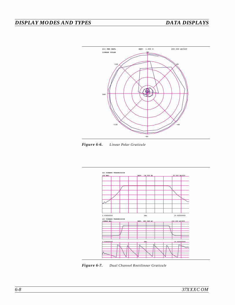
DISPLAY MODES AND TYPES DATA DISPLAYS
6-8 37XXXC OM
00
45
90
135
180
-135
-90
-45
S11 FWD REFL
LINEAR POLAR
REF= 1.000 U 200.000 mU/DIV
Figure 6-6. Linear Polar Graticule
GHz2.036000000 10.020000000
S21 FORWARD TRANSMISSION
LOG MAG. REF= -38.569 dB 20.000 dB/DIV
GHz2.036000000 10.020000000
S21 FORWARD TRANSMISSION
LINEAR MAG. REF= 483.588 mU 200.000 mU/DIV
Figure 6-7. Dual Channel Rectilinear Graticule
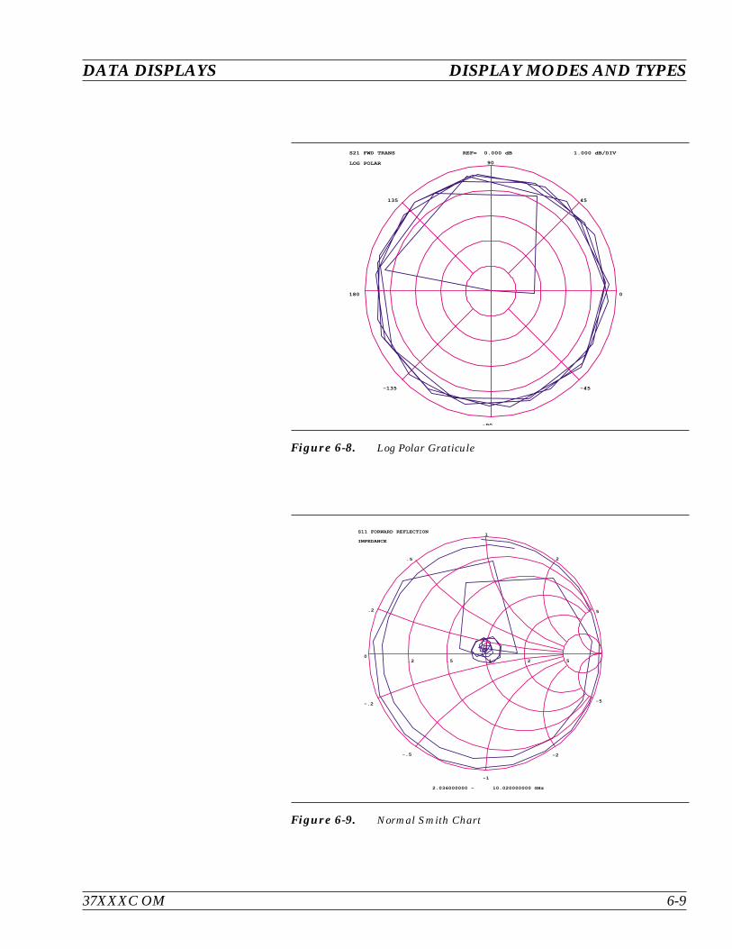
37XXXC OM 6-9
DATA DISPLAYS DISPLAY MODES AND TYPES
0
45
90
135
180
-135
-90
-45
S21 FWD TRANS
LOG POLAR
REF= 0.000 dB 1.000 dB/DIV
Figure 6-8. Log Polar Graticule
0.2 .5 1 2 5
.2
-.2
.5
-.5
1
-1
2
-2
5
-5
2.036000000 - 10.020000000 GHz
S11 FORWARD REFLECTION
IMPEDANCE
Figure 6-9. Normal Smith Chart
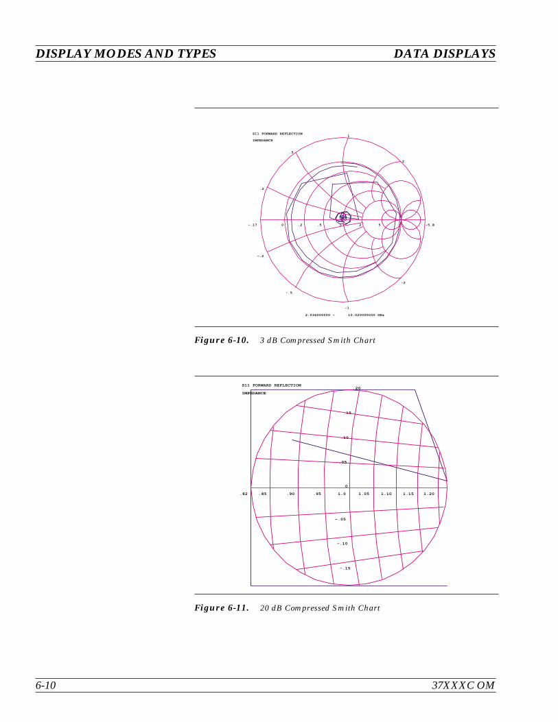
DISPLAY MODES AND TYPES DATA DISPLAYS
6-10 37XXXC OM
-.17 0 .2 .5 1 2 5 -5.8
.2
-.2
.5
-.5
1
-1
2
-2
2.036000000 - 10.020000000 GHz
S11 FORWARD REFLECTION
IMPEDANCE
Figure 6-10. 3 dB Compressed Smith Chart
.82 .85 .90 .95 1.0 1.05 1.10 1.15 1.20
.20
20
.15
-.15
.10
-.10
.05
-.05
0
S11 FORWARD REFLECTION
IMPEDANCE
Figure 6-11. 20 dB Compressed Smith Chart

6-3 FREQUENCY MARKERS The example below shows how the 37XXXC annotates markers for thedifferent graph-types. Each marker is identified with its own number.When a marker reaches the top of its graticule, it will flip over and itsnumber will appear below the symbol. When markers approach thesame frequency, they will overlap. Their number will appear as close tothe marker as possible without overlapping.
Marker Designation Depending on menu selection, you may designate a marker as the “ac-tive” or the “delta reference” marker. If you choose a marker to be ac-tive—indicated by its number being enclosed in a square box—youmay change its frequency or time (distance) (or point number in CWDraw) with the Data Entry keypad or knob. If you have chosen it to bethe delta-reference marker, a delta symbol ( ) appears one characterspace above the marker number (or one character space below a“flipped” marker). If the marker is both active and the delta referencemarker, the number and the delta symbol appear above (below) themarker. The delta symbol appears above (below) the number.
6-4 LIMITS Limit lines function as settable maximum and minimum indicators forthe value of displayed data. These lines are settable in the basic unitsof the measurement on a channel-by-channel basis. If the display isrescaled, the limit line(s) will move automatically and thereby main-tain their correct value(s).
37XXXC OM 6-11
DATA DISPLAYS FREQUENCY MARKERS
0
.2
-.2
.5
-.5
1
-1
2
-2
5
-5
S11
Z
GHz2.036000000 10.020000000
S12 LOGM+P
-20.000 dB
3.91|
10.000 dB/DIV
60.00| /DIV
GHz2.036000000 10.020000000
S21 LOGM+P
0.000 dB
7.99|
10.000 dB/DIV
60.00| /DIV
0
.2
-.2
.5
-.5
1
-1
2
-2
5
-5
S22
Z
1
2
3
12
3
12 3
1
2
3
1
2
3
1
2
3
Figure 6-12. Marker Annotation
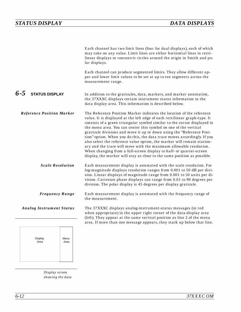
Each channel has two limit lines (four for dual displays), each of whichmay take on any value. Limit lines are either horizontal lines in recti-linear displays or concentric circles around the origin in Smith and po-lar displays.
Each channel can produce segmented limits. They allow different up-per and lower limit values to be set at up to ten segments across themeasurement range.
6-5 STATUS DISPLAY In addition to the graticules, data, markers, and marker annotation,the 37XXXC displays certain instrument status information in thedata display area. This information is described below.
Reference Position Marker The Reference Position Marker indicates the location of the referencevalue. It is displayed at the left edge of each rectilinear graph-type. Itconsists of a green triangular symbol similar to the cursor displayed inthe menu area. You can center this symbol on one of the verticalgraticule divisions and move it up or down using the “Reference Posi-tion” option. When you do this, the data trace moves accordingly. If youalso select the reference value option, the marker will remain station-ary and the trace will move with the maximum allowable resolution.When changing from a full-screen display to half- or quarter-screendisplay, the marker will stay as close to the same position as possible.
Scale Resolution Each measurement display is annotated with the scale resolution. Forlog-magnitude displays resolution ranges from 0.001 to 50 dB per divi-sion. Linear displays of magnitude range from 0.001 to 50 units per di-vision. Cartesian phase displays can range from 0.01 to 90 degrees perdivision. The polar display is 45 degrees per display graticule.
Frequency Range Each measurement display is annotated with the frequency range ofthe measurement.
Analog Instrument Status The 37XXXC displays analog-instrument-status messages (in redwhen appropriate) in the upper right corner of the data-display area(left). They appear at the same vertical position as line 2 of the menuarea. If more than one message appears, they stack up below that line.
STATUS DISPLAY DATA DISPLAYS
6-12 37XXXC OM
Display screenshowing the data
MenuArea
DisplayArea
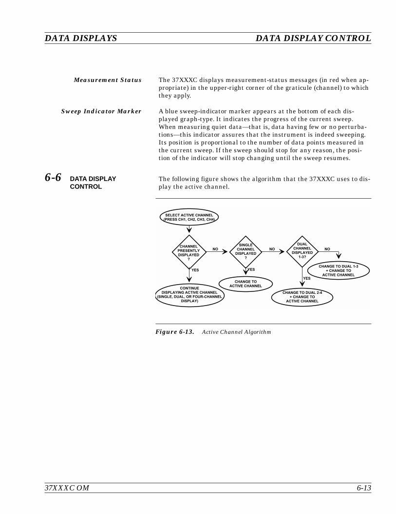
Measurement Status The 37XXXC displays measurement-status messages (in red when ap-propriate) in the upper-right corner of the graticule (channel) to whichthey apply.
Sweep Indicator Marker A blue sweep-indicator marker appears at the bottom of each dis-played graph-type. It indicates the progress of the current sweep.When measuring quiet data—that is, data having few or no perturba-tions—this indicator assures that the instrument is indeed sweeping.Its position is proportional to the number of data points measured inthe current sweep. If the sweep should stop for any reason, the posi-tion of the indicator will stop changing until the sweep resumes.
6-6 DATA DISPLAYCONTROL
The following figure shows the algorithm that the 37XXXC uses to dis-play the active channel.
37XXXC OM 6-13
DATA DISPLAYS DATA DISPLAY CONTROL
!
" #!
$ " $ $ #
$ $ %
Figure 6-13. Active Channel Algorithm
S-parameter Selection If you select a new S-parameter using Menu SP (Appendix A), it ap-pears on the then-active channel in the same graph-type in which itwas last displayed. The following table shows the displayable S-pa-rameters based on the correction type you have in place. If you at-tempt to display other S-parameters, an error message appears. Incases when there is no last-displayed S-parameter stored, the displaywill default as shown. If an S-parameter is selected for which therewas no last-displayed graph-type, the display defaults to S21, S12 LogMagnitude and Phase and S11, S22 Smith.
Data Display Update When you change a control panel parameter that affects the appear-ance of the display, the entire display changes immediately to reflectthat change. For example, if you press Autoscale, the entire displayrescales immediately. You do not have to wait for the next sweep to seethe results of the change. The following parameters are supported forthis feature: Reference Delay, Offset, Scaling, Auto Scale, Auto Refer-ence Delay, Trace Math, IF BW, and Smoothing. In the case of Aver-aging, the sweep restarts.
If the knob is used to vary any of the above parameters, the change oc-curs as the measurement progresses–that is, the continuing trace willreflect the new setting(s).
When you change a marker frequency or time (distance), the readoutparameters will change. This change reflects the changes in measure-ment data at the marker’s new frequency, using data stored from theprevious sweep.
Display of Markers Once you have selected a marker to display, it will appear on thescreen. It does not matter what resolution you have selected. Whenyou set a marker to another calibrated frequency and then lower the
DATA DISPLAY CONTROL DATA DISPLAYS
6-14 37XXXC OM
Correction Type DisplayableS-parameters
Default Display Position
CH1 CH2 CH3 CH4
None All S11 S12 S21 S22
FrequencyResponse
Reverse Transmission S12 S12
Forward Transmission S21 S21
Both S12, S21 S12 S21
Port 1 Reflection Only S11 S11
Port 2Reflection Only S22 S22
Reflection Only, Both S11, S22 S11 S22
Forward 1-Path 2-Port S11, S21 S11 S21
Reverse 1-Path 2-Port S12, S22 S12 S22
12-Term All S11 S12 S21 S22

resolution, that frequency and the marker will continue to display. Itwill display even if its frequency is not consistent with the data pointsin the lower-resolution sweep.
6-7 HARD COPY AND DISKOUTPUT
In addition to the LCD screen, the Model 37XXXC is capable of output-ting measured data as a:
Tabular Printout
Screen-Image Printout
Pen Plot
Disk Image of the Tabular Data Values
The selection and initiation of this output is controlled by the HardCopy keys.
Tabular Printout An example of a tabular format is shown in Figure 6-14 (page 6-16).The tabular formats are used as follows:
Tabular Printout Format: Used when printing three or four chan-nels.
Alternate Data Format: Used when printing one or two channels.
In tabular printouts, the 37XXXC shifts the data columns to the leftwhen an S-Parameter is omitted. Leading zeroes are always sup-pressed. The heading (Model, Device ID, Date, Operator, Page) appearson each page.
Screen-Image Printout In a Screen-Image Printout, the exact data displayed on the screen isdumped to the printer. The dump is in the graphics mode, on apixel-by-pixel basis.
Plotter Output The protocol used to control plotters is “HP-GL (Hewlett-PackardGraphics Language). HP-GL contains a comprehensive set of vectorgraphics type commands. These commands are explained in the Inter-facing and Programming Manual for any current modelHewlett-Packard plotter, such as the 7470A.
When the plotter is selected as the output device, it is capable of draw-ing the graph shown on the screen or of drawing only the data trace(s).Multiple traces may be drawn on a single sheet of paper (in differentcolors, if needed).
Disk Output The 37XXXC can write-to or read-from the disk all measured data.This data is stored as an ASCII file in the exact same format as thatshown for the tabular printout in Figure 6-14 (page 6-16). If read backfrom the disk, the data is output to the printer. There, it prints astabular data.
37XXXC OM 6-15
DATA DISPLAYS HARD COPY AND DISK OUTPUT
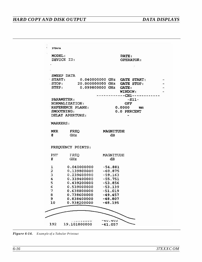
HARD COPY AND DISK OUTPUT DATA DISPLAYS
6-16 37XXXC OM
Figure 6-14. Example of a Tabular Printout
Table of Contents
7-1 INTRODUCTION . . . . . . . . . . . . . . . . . . . . . . . . . . . . . . . . . . . 7-3
7-2 DISCUSSION . . . . . . . . . . . . . . . . . . . . . . . . . . . . . . . . . . . . . 7-3
Establishing the Test Ports . . . . . . . . . . . . . . . . . . . . . . . . . . . . . 7-3
Understanding the Calibration System . . . . . . . . . . . . . . . . . . . . . . 7-5
Calibrating for a Measurement . . . . . . . . . . . . . . . . . . . . . . . . . . 7-9
Evaluating the Calibration . . . . . . . . . . . . . . . . . . . . . . . . . . . . 7-11
Verification Kits . . . . . . . . . . . . . . . . . . . . . . . . . . . . . . . . . . 7-11
7-3 SLIDING TERMINATION . . . . . . . . . . . . . . . . . . . . . . . . . . . . . . 7-13
7-4 SOLT CALIBRATION . . . . . . . . . . . . . . . . . . . . . . . . . . . . . . . . 7-19
Calibration Procedure . . . . . . . . . . . . . . . . . . . . . . . . . . . . . . . 7-19
7-5 OFFSET-SHORT CALIBRATION (SSLT) . . . . . . . . . . . . . . . . . . . . . . 7-28
Calibration Procedure . . . . . . . . . . . . . . . . . . . . . . . . . . . . . . . 7-28
7-6 TRIPLE OFFSET-SHORT CALIBRATION (SSST) . . . . . . . . . . . . . . . . . 7-32
Calibration Procedure . . . . . . . . . . . . . . . . . . . . . . . . . . . . . . . 7-32
7-7 LRL/LRM CALIBRATION . . . . . . . . . . . . . . . . . . . . . . . . . . . . . . 7-36
7-8 TRM CALIBRATION . . . . . . . . . . . . . . . . . . . . . . . . . . . . . . . . . 7-46
7-9 MERGE CAL FILES APPLICATION . . . . . . . . . . . . . . . . . . . . . . . . 7-47
Chapter 7MeasurementCalibration

IMPORTANT NOTEThe 37100C Direct Access Receiver cannot make S-parameter measurements without an ex-ternal reflectometer setup. This manual describes calibration and S-parameter measure-ments for the 372XXC and 373XXC. Most of these measurements can also be used with the371XXC assuming the user understands the need for an external reflectometer. Anritsu of-fers an optional reflectometer test set that can be used. This reflectometer is described and adrawing is shown in the Technical Data Sheet provided as Appendix C in this manual.
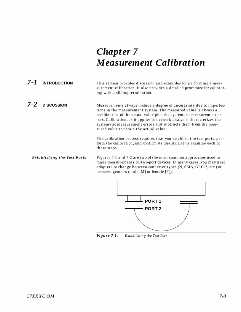
Chapter 7Measurement Calibration
7-1 INTRODUCTION This section provides discussion and examples for performing a mea-surement calibration. It also provides a detailed procedure for calibrat-ing with a sliding termination.
7-2 DISCUSSION Measurements always include a degree of uncertainty due to imperfec-tions in the measurement system. The measured value is always acombination of the actual value plus the systematic measurement er-rors. Calibration, as it applies to network analysis, characterizes thesystematic measurement errors and subtracts them from the mea-sured value to obtain the actual value.
The calibration process requires that you establish the test ports, per-form the calibration, and confirm its quality. Let us examine each ofthese steps.
Establishing the Test Ports Figures 7-1 and 7-2 are two of the most common approaches used tomake measurements on two-port devices. In many cases, you may needadapters to change between connector types (N, SMA, GPC-7, etc.) orbetween genders (male [M] or female [F]).
37XXXC OM 7-3
PORT 1
PORT 2
Figure 7-1. Establishing the Test Port
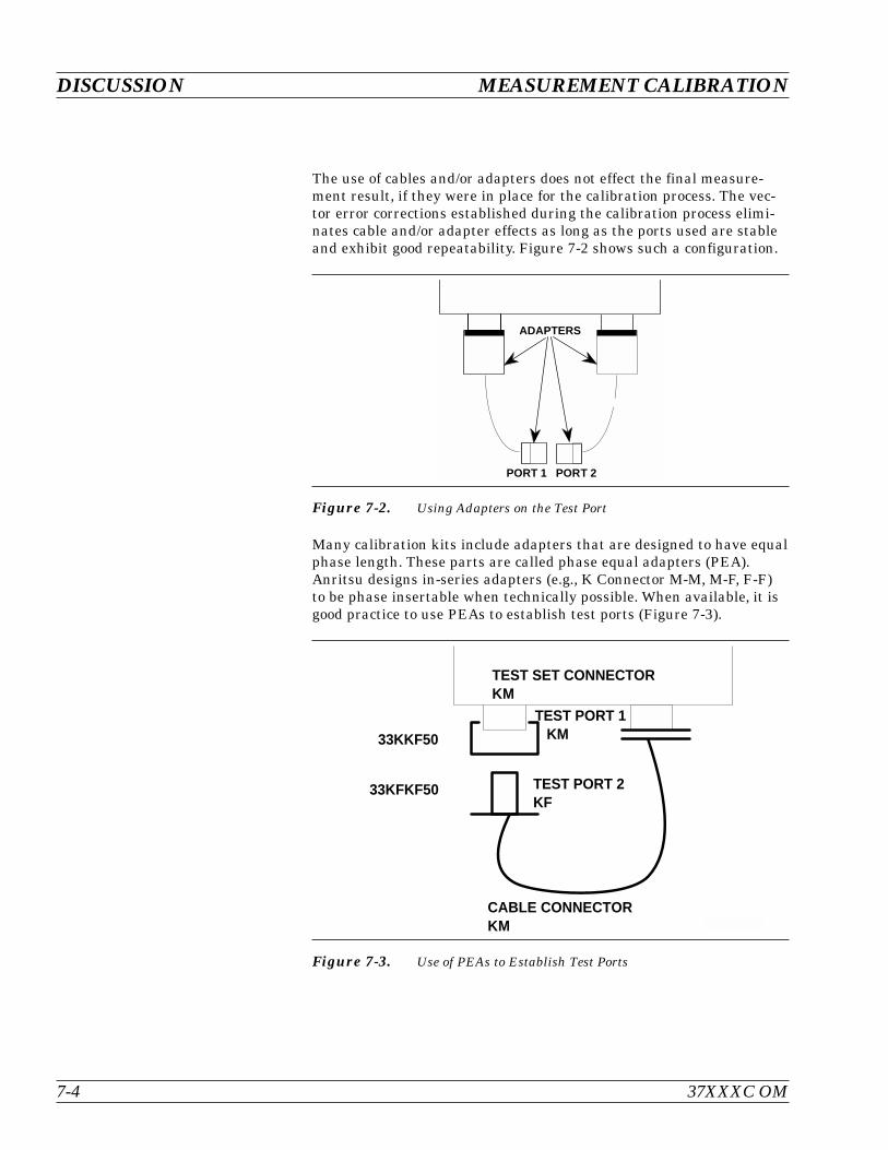
The use of cables and/or adapters does not effect the final measure-ment result, if they were in place for the calibration process. The vec-tor error corrections established during the calibration process elimi-nates cable and/or adapter effects as long as the ports used are stableand exhibit good repeatability. Figure 7-2 shows such a configuration.
Many calibration kits include adapters that are designed to have equalphase length. These parts are called phase equal adapters (PEA).Anritsu designs in-series adapters (e.g., K Connector M-M, M-F, F-F)to be phase insertable when technically possible. When available, it isgood practice to use PEAs to establish test ports (Figure 7-3).
DISCUSSION MEASUREMENT CALIBRATION
7-4 37XXXC OM
PORT 1 PORT 2
ADAPTERS
Figure 7-2. Using Adapters on the Test Port
33KKF50
33KFKF50
TEST SET CONNECTORKM
TEST PORT 1 KM
TEST PORT 2KF
CABLE CONNECTORKM
Figure 7-3. Use of PEAs to Establish Test Ports
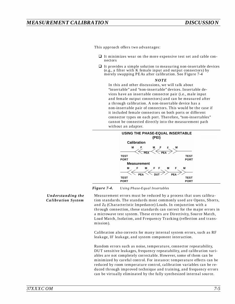
This approach offers two advantages:
It minimizes wear on the more expensive test set and cable con-nectors
It provides a simple solution to measuring non-insertable devices(e.g., a filter with K female input and output connectors) bymerely swapping PEAs after calibration. See Figure 7-4
NOTEIn this and other discussions, we will talk about“insertable” and “non-insertable” devices. Insertable de-vices have an insertable connector pair (i.e., male inputand female output connectors) and can be measured aftera through calibration. A non-insertable device has anon-insertable pair of connectors. This would be the case ifit included female connectors on both ports or differentconnector types on each port. Therefore, “non-insertables”cannot be connected directly into the measurement pathwithout an adapter.
Understanding theCalibration System
Measurement errors must be reduced by a process that uses calibra-tion standards. The standards most commonly used are Opens, Shorts,and Z0 (Characteristic Impedance) Loads. In conjunction with athrough connection, these standards can correct for the major errors ina microwave test system. These errors are Directivity, Source Match,Load Match, Isolation, and Frequency Tracking (reflection and trans-mission).
Calibration also corrects for many internal system errors, such as RFleakage, IF leakage, and system component interaction.
Random errors such as noise, temperature, connector repeatability,DUT sensitive leakages, frequency repeatability, and calibration vari-ables are not completely correctable. However, some of them can beminimized by careful control. For instance: temperature effects can bereduced by room temperature control, calibration variables can be re-duced through improved technique and training, and frequency errorscan be virtually eliminated by the fully synthesized internal source.
37XXXC OM 7-5
MEASUREMENT CALIBRATION DISCUSSION
Calibration
Measurement
M F
PEA
USING THE PHASE-EQUAL INSERTABLE(PEI)
F MF
M F M F MFMF
DUTTESTPORT
TESTPORT
TESTPORT
TESTPORT
PEA
PEA
PEA
M
Figure 7-4. Using Phase-Equal Insertables
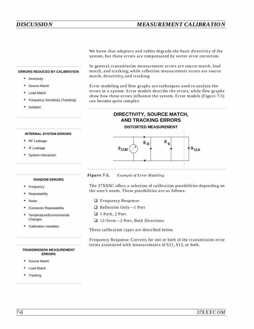
We know that adapters and cables degrade the basic directivity of thesystem, but these errors are compensated by vector error correction.
In general, transmission measurement errors are source match, loadmatch, and tracking; while reflection measurement errors are sourcematch, directivity, and tracking.
Error modeling and flow graphs are techniques used to analyze theerrors in a system. Error models describe the errors, while flow graphsshow how these errors influence the system. Error models (Figure 7-5)can become quite complex.
The 37XXXC offers a selection of calibration possibilities depending onthe user’s needs. These possibilities are as follows:
Frequency Response
Reflection Only—1 Port
1 Path, 2 Port
12-Term—2 Port, Both Directions
These calibration types are described below.
Frequency Response: Corrects for one or both of the transmission errorterms associated with measurements of S21, S12, or both.
DISCUSSION MEASUREMENT CALIBRATION
7-6 37XXXC OM
INTERNAL SYSTEM ERRORS
RF Leakage
IF Leakage
System Interaction
RANDOM ERRORS
Frequency
Repeatability
Noise
Connector Repeatability
Temperature/EnvironmentalChanges
Calibration Variables
ERRORS REDUCED BY CALIBRATION
Directivity
Source Match
Load Match
Frequency Sensitivity (Tracking)
Isolation
DIRECTIVITY, SOURCE MATCH,AND TRACKING ERRORS
DISTORTED MEASUREMENT
S11M
E DS 11A
E S
Figure 7-5. Example of Error Modeling
TRANSMISSION MEASUREMENTERRORS
Source Match
Load Match
Tracking
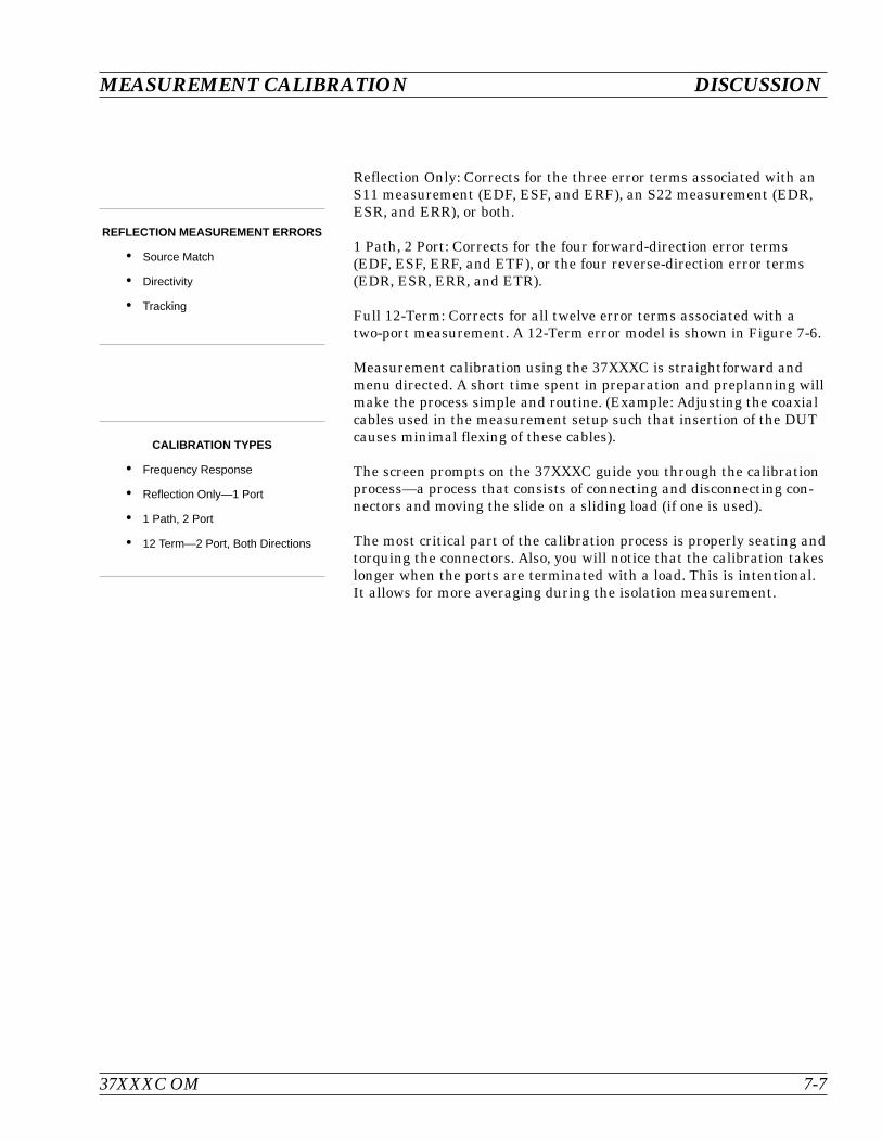
Reflection Only: Corrects for the three error terms associated with anS11 measurement (EDF, ESF, and ERF), an S22 measurement (EDR,ESR, and ERR), or both.
1 Path, 2 Port: Corrects for the four forward-direction error terms(EDF, ESF, ERF, and ETF), or the four reverse-direction error terms(EDR, ESR, ERR, and ETR).
Full 12-Term: Corrects for all twelve error terms associated with atwo-port measurement. A 12-Term error model is shown in Figure 7-6.
Measurement calibration using the 37XXXC is straightforward andmenu directed. A short time spent in preparation and preplanning willmake the process simple and routine. (Example: Adjusting the coaxialcables used in the measurement setup such that insertion of the DUTcauses minimal flexing of these cables).
The screen prompts on the 37XXXC guide you through the calibrationprocess—a process that consists of connecting and disconnecting con-nectors and moving the slide on a sliding load (if one is used).
The most critical part of the calibration process is properly seating andtorquing the connectors. Also, you will notice that the calibration takeslonger when the ports are terminated with a load. This is intentional.It allows for more averaging during the isolation measurement.
37XXXC OM 7-7
MEASUREMENT CALIBRATION DISCUSSION
REFLECTION MEASUREMENT ERRORS
Source Match
Directivity
Tracking
CALIBRATION TYPES
Frequency Response
Reflection Only—1 Port
1 Path, 2 Port
12 Term—2 Port, Both Directions
DISCUSSION MEASUREMENT CALIBRATION
7-8 37XXXC OM
PORT 1 PORT 2
RF IN
PORT 1 PORT 2
PORT 1 PORT 1PORT 2 PORT 2
PORT 1 PORT 2 PORT 1 PORT 2
RF IN RF IN
RF INRF IN
DUT DUT
DUTDUT
DUT
DUT
12 - TERM
ELFDFE
TFE
TRE
SRE DRE
RFE
S12
S21
S11LRE22S
RRE
S21
S21 S21
R
S11
S11
S11 S11
S12
DFE
DFE
22S
RFE
TFE
TFE
RFE
RFE EXR
1
1
Forward Direction Terms Reverse Direction Terms
1 Path - 2 Port Terms
Reflection Only Terms
Frequency Response - Transmission Only Terms
Frequency Response - Reflection Only Terms
EXF
ESF
S21M
ESF
11MS
11MS
S21M
S12M
S
S
22
21
E
S11M
SF
EXF
Figure 7-6. Error Models
Calibrating for aMeasurement
Let us assume that we want to correct for three errors in the reflectionmeasurement: source match, directivity, and tracking. We accomplishthis using three standards.
Shorts are the easiest to visualize. They totally reflect all of the inci-dent RF energy output at a precise phase. The terms zero-ohms imped-ance, voltage null, and 180° phase all define an RF Short.
Opens are similar to Shorts, but their response is more complex. Theterms voltage maximum, infinite impedance, and 0° phase all define aperfect Open. A perfect Open, however, is only a concept. In realityOpens always have a small fringing capacitance.
To account for the fact that the Open will not predictably reflect im-pedance at an exact 0° phase reference, we alter its response using co-efficients that accurately characterize the fringing capacitance. The co-efficients are different for each coaxial line size, since each size has adifferent fringing capacitance. To maximize accuracy, ensure thatthese coefficients are installed prior to the calibration (Menu U3).
As Opens and Shorts provide two references for a full reflection, Z0 ter-minations provide a zero-reflection reference.
Ideal Z0 terminations must consist of two parts, a perfect connectorand an infinite-length perfect transmission line that absorbs all of theRF energy that enters it (no reflections).
Infinite length transmission lines are unwieldy at best, so you mustuse less-than-ideal terminations. For calibration purposes there aretwo common types: broadband loads and sliding terminations.
37XXXC OM 7-9
MEASUREMENT CALIBRATION DISCUSSION
CALIBRATING FOR A REFLECTIONMEASUREMENT USES THREE
STANDARDS:
Short
Open
Termination
IDEAL TERMINATIONS
Reflectionless
Perfect Connector
Infinite-Length, Dimensionally Ex-act, Reflectionless TransmissionLine
PRACTICAL Zo TERMINATIONS
Broadband Load
Sliding Termination
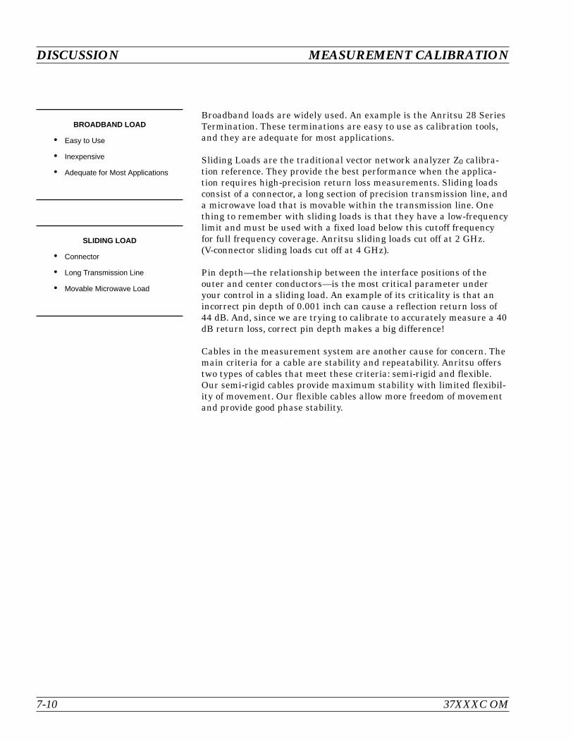
Broadband loads are widely used. An example is the Anritsu 28 SeriesTermination. These terminations are easy to use as calibration tools,and they are adequate for most applications.
Sliding Loads are the traditional vector network analyzer Z0 calibra-tion reference. They provide the best performance when the applica-tion requires high-precision return loss measurements. Sliding loadsconsist of a connector, a long section of precision transmission line, anda microwave load that is movable within the transmission line. Onething to remember with sliding loads is that they have a low-frequencylimit and must be used with a fixed load below this cutoff frequencyfor full frequency coverage. Anritsu sliding loads cut off at 2 GHz.(V-connector sliding loads cut off at 4 GHz).
Pin depth—the relationship between the interface positions of theouter and center conductors—is the most critical parameter underyour control in a sliding load. An example of its criticality is that anincorrect pin depth of 0.001 inch can cause a reflection return loss of44 dB. And, since we are trying to calibrate to accurately measure a 40dB return loss, correct pin depth makes a big difference!
Cables in the measurement system are another cause for concern. Themain criteria for a cable are stability and repeatability. Anritsu offerstwo types of cables that meet these criteria: semi-rigid and flexible.Our semi-rigid cables provide maximum stability with limited flexibil-ity of movement. Our flexible cables allow more freedom of movementand provide good phase stability.
DISCUSSION MEASUREMENT CALIBRATION
7-10 37XXXC OM
BROADBAND LOAD
Easy to Use
Inexpensive
Adequate for Most Applications
SLIDING LOAD
Connector
Long Transmission Line
Movable Microwave Load
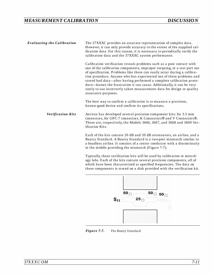
Evaluating the Calibration The 37XXXC provides an accurate representation of complex data.However, it can only provide accuracy to the extent of the supplied cal-ibration data. For this reason, it is necessary to periodically verify thecalibration data and the 37XXXC system performance.
Calibration verification reveals problems such as a poor contact withone of the calibration components, improper torquing, or a test port outof specification. Problems like these can easily occur during a calibra-tion procedure. Anyone who has experienced one of these problems andstored bad data—after having performed a complete calibration proce-dure—knows the frustration it can cause. Additionally, it can be verycostly to use incorrectly taken measurement data for design or qualityassurance purposes.
The best way to confirm a calibration is to measure a precision,known-good device and confirm its specifications.
Verification Kits Anritsu has developed several precision-component kits: for 3.5 mmconnectors, for GPC-7 connectors, K Connectors and V Connectors.These are, respectively, the Models 3666, 3667, and 3668 and 3669 Ver-ification Kits.
Each of the kits contain 20 dB and 50 dB attenuators, an airline, and aBeatty Standard. A Beatty Standard is a two-port mismatch similar toa beadless airline. It consists of a center conductor with a discontinuityin the middle providing the mismatch (Figure 7-7).
Typically, these verification kits will be used by calibration or metrol-ogy labs. Each of the kits contain several precision components, all ofwhich have been characterized at specified frequencies. The data onthese components is stored on a disk provided with the verification kit.
37XXXC OM 7-11
MEASUREMENT CALIBRATION DISCUSSION
& ' " &
& ' & '
Figure 7-7. The Beatty Standard

The verification of the kit components is straight forward. The compo-nents are first measured with the 37XXXC, then they are comparedwith the data recorded on the disk. If the measured data compares fa-vorably with the recorded data (taking tolerances into consideration),then the system is known to be operating properly and providing accu-rate data.
There is one caution that you need to observe when using VerificationKits. Because the verification components have been characterized,you must handle them carefully so that you do not change their knowncharacteristics. Consequently, you should not have them available fordaily use. Rather, you should only use them for the accuracy verifica-tion checks taken every 6-to-12 months (or at any other time the sys-tem’s integrity is in doubt).
This completes the discussion on calibration. Refer to paragraph 7-3for a procedure showing how to calibrate the sliding load.
DISCUSSION MEASUREMENT CALIBRATION
7-12 37XXXC OM

7-3 SLIDING TERMINATION Sliding terminations (loads) are the traditional Z0 calibration-refer-ence devices for vector network analyzer calibration. When correctlyused and perfectly aligned, they can be more accurate than precisionfixed loads. However, sliding terminations have a 2 GHz (4 GHz forV-Connector sliding loads) low-frequency limit and must be used witha fixed load for full frequency-range coverage.
Sliding terminations consist of a connector, a long section of precisiontransmission line, and a microwave load that is movable within thetransmission line. Pin depth—the relationship between the interfacepositions of the outer and center conductors—is the most critical pa-rameter that you can control in a sliding termination. An example ofits criticality is that an incorrect pin depth of 0.001 inch can cause areflection return loss of 44 dB. Since you are usually calibrating to ac-curately measure a greater than 40 dB return loss, correct pin depth isessential.
Since setting an accurate pin depth is so important, this discussioncenters on describing how to set the pin depth for male and femalesliding terminations. Calibration with the sliding termination is essen-tially the same as described below for the broadband load.
The procedure below uses the Model 3652 Calibration Kit and its17KF50 and 17K50 Sliding Terminations. Calibration is similar for theModel 3650 SMA/3.5mm, Model 3651 GPC-7 and Model 3654 V con-nector kits. For the 3651, the procedure is simpler because the GPC-7connector is genderless, there are no male and female versions.
Procedure
Step 1. Remove the Pin Depth Gauge from the kit, place iton the bench top.
NOTEThe gauge is convertible between male and female. Thefollowing procedure describes the zeroing process for thefemale fitting. The procedure for the male fitting beginswith Step 16.
37XXXC OM 7-13
MEASUREMENT CALIBRATION SLIDING TERMINATION

Step 2. Push the outer locking ring towards the gauge to ex-pose the center pin.
Step 3. Take the 01-210 Ref Flat from the kit.
Step 4. While holding the gauge as shown, press the RefFlat firmly against the end of the exposed centerpin.
SLIDING TERMINATION MEASUREMENT CALIBRATION
7-14 37XXXC OM
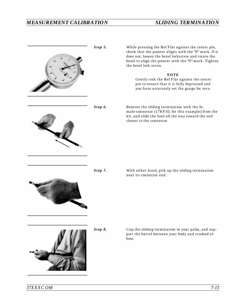
Step 5. While pressing the Ref Flat against the center pin,check that the pointer aligns with the “0” mark. If itdoes not, loosen the bezel lockscrew and rotate thebezel to align the pointer with the “0” mark. Tightenthe bezel lock screw.
NOTEGently rock the Ref Flat against the centerpin to ensure that it is fully depressed andyou have accurately set the gauge for zero.
Step 6. Remove the sliding termination with the fe-male-connector (17KF50, for this example) from thekit, and slide the load all the way toward the endclosest to the connector.
Step 7. With either hand, pick up the sliding terminationnear its connector end.
Step 8. Cup the sliding termination in your palm, and sup-port the barrel between your body and crooked el-bow.
37XXXC OM 7-15
MEASUREMENT CALIBRATION SLIDING TERMINATION
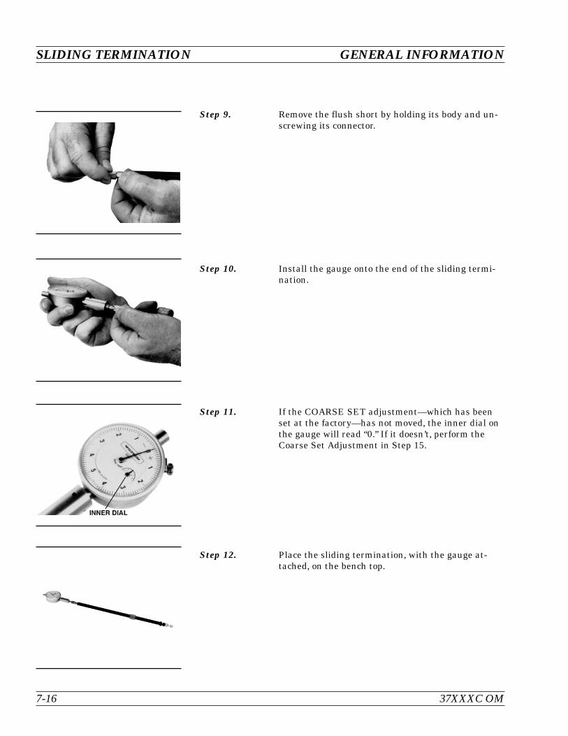
Step 9. Remove the flush short by holding its body and un-screwing its connector.
Step 10. Install the gauge onto the end of the sliding termi-nation.
Step 11. If the COARSE SET adjustment—which has beenset at the factory—has not moved, the inner dial onthe gauge will read “0.” If it doesn’t, perform theCoarse Set Adjustment in Step 15.
Step 12. Place the sliding termination, with the gauge at-tached, on the bench top.
SLIDING TERMINATION GENERAL INFORMATION
7-16 37XXXC OM
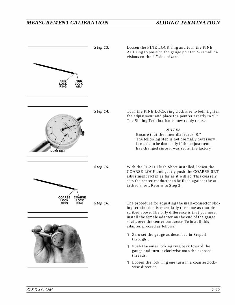
Step 13. Loosen the FINE LOCK ring and turn the FINEADJ ring to position the gauge pointer 2-3 small di-visions on the “–” side of zero.
Step 14. Turn the FINE LOCK ring clockwise to both tightenthe adjustment and place the pointer exactly to “0.”The Sliding Termination is now ready to use.
NOTESEnsure that the inner dial reads “0.”The following step is not normally necessary.It needs to be done only if the adjustmenthas changed since it was set at the factory.
Step 15. With the 01-211 Flush Short installed, loosen theCOARSE LOCK and gently push the COARSE SETadjustment rod in as far as it will go. This coarselysets the center conductor to be flush against the at-tached short. Return to Step 2.
Step 16. The procedure for adjusting the male-connector slid-ing termination is essentially the same as that de-scribed above. The only difference is that you mustinstall the female adapter on the end of the gaugeshaft, over the center conductor. To install thisadapter, proceed as follows:
Zero-set the gauge as described in Steps 2through 5.
Push the outer locking ring back toward thegauge and turn it clockwise onto the exposedthreads.
Loosen the lock ring one turn in a counterclock-wise direction.
37XXXC OM 7-17
MEASUREMENT CALIBRATION SLIDING TERMINATION

Step 17. Remove the 01-223 Female Adapter (“F ADAPTERFOR PIN GAUGE”) from the kit.
Step 18. Install the female adapter over the center pin andscrew it into the locking ring, and tighten the outerring until it is snug against the housing.
Step 19. Inspect the end of the adapter, you should see nomore than two exposed threads. If so, repeat Steps 7through 10.
Step 20. Connect the gauge to the sliding termination andzero set the center pin using the FINE ADJ as pre-viously described in Steps 2 through 5.
SLIDING TERMINATION GENERAL INFORMATION
7-18 37XXXC OM

7-4 SOLT CALIBRATION The SOLT calibration for the 37XXXC Vector Network Analyzer sys-tem uses a Short, Open, Load, and a Thru line connection to categorizethe inherent errors in the measurement system. These errors includethose caused by connectors as well as internal system errors such asRF leakage, IF leakage, and component interaction. For maximum ac-curacy, install the capacitive coefficients (for the open device) usingMenu U3.
NOTEThe SOLT calibration, in conjuction with the SSST calibra-tion, are merged to create a continuous, single sweep broad-band calibration on the ME7808A system. Refer to Chapter15 for details about the broadband mode of operation.
Calibration Procedure A detailed, step-by-step procedure for performing aShort-Open-Load-Throughline calibration is given below.
Step 1. Press the Begin Cal key.
Step 2. Select CHANGE CAL METHOD AND LINETYPE, in menu C11 (left). (This assumes SOLT andCOAXIAL are not presently shown in blue as beingselected.)
37XXXC OM 7-19
MEASUREMENT CALIBRATION SOLT CALIBRATION
ApplyCal
BeginCal
MENU C11
BEGIN CALIBRATION
KEEP EXISTINGCAL DATA
REPEATPREVIOUS CAL
AUTOCAL
CAL METHODSTANDARD
TRANSMISSIONLINE TYPE:XXXXXXXX
CHANGE CALMETHOD ANDLINE TYPE
NEXT CAL STEP
PRESS <ENTER>TO SELECT
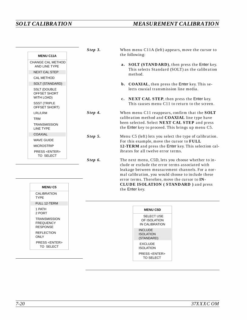
Step 3. When menu C11A (left) appears, move the cursor tothe following:
a. SOLT (STANDARD), then press the Enter key.This selects Standard (SOLT) as the calibrationmethod.
b. COAXIAL, then press the Enter key. This se-lects coaxial transmission line media.
c. NEXT CAL STEP, then press the Enter key.This causes menu C11 to return to the screen.
Step 4. When menu C11 reappears, confirm that the SOLTcalibration method and COAXIAL line type havebeen selected. Select NEXT CAL STEP and pressthe Enter key to proceed. This brings up menu C5.
Step 5. Menu C5 (left) lets you select the type of calibration.For this example, move the cursor to FULL12-TERM and press the Enter key. This selection cal-ibrates for all twelve error terms.
Step 6. The next menu, C5D, lets you choose whether to in-clude or exclude the error terms associated withleakage between measurement channels. For a nor-mal calibration, you would choose to include theseerror terms. Therefore, move the cursor to IN-CLUDE ISOLATION ( STANDARD ) and pressthe Enter key.
SOLT CALIBRATION MEASUREMENT CALIBRATION
7-20 37XXXC OM
MENU C11A
CHANGE CAL METHODAND LINE TYPE
NEXT CAL STEP
CAL METHOD
SOLT (STANDARD)
SSLT (DOUBLEOFFSET SHORTWITH LOAD)
SSST (TRIPLEOFFSET SHORT)
LRL/LRM
TRM
TRANSMISSIONLINE TYPE
COAXIAL
WAVE GUIDE
MICROSTRIP
PRESS <ENTER>TO SELECT
MENU C5
CALIBRATIONTYPE
FULL 12-TERM
1 PATH2 PORT
TRANSMISSIONFREQUENCYRESPONSE
REFLECTIONONLY
PRESS <ENTER>TO SELECT
MENU C5D
SELECT USEOF ISOLATION
IN CALIBRATION
INCLUDEISOLATION(STANDARD)
EXCLUDEISOLATION
PRESS <ENTER>TO SELECT
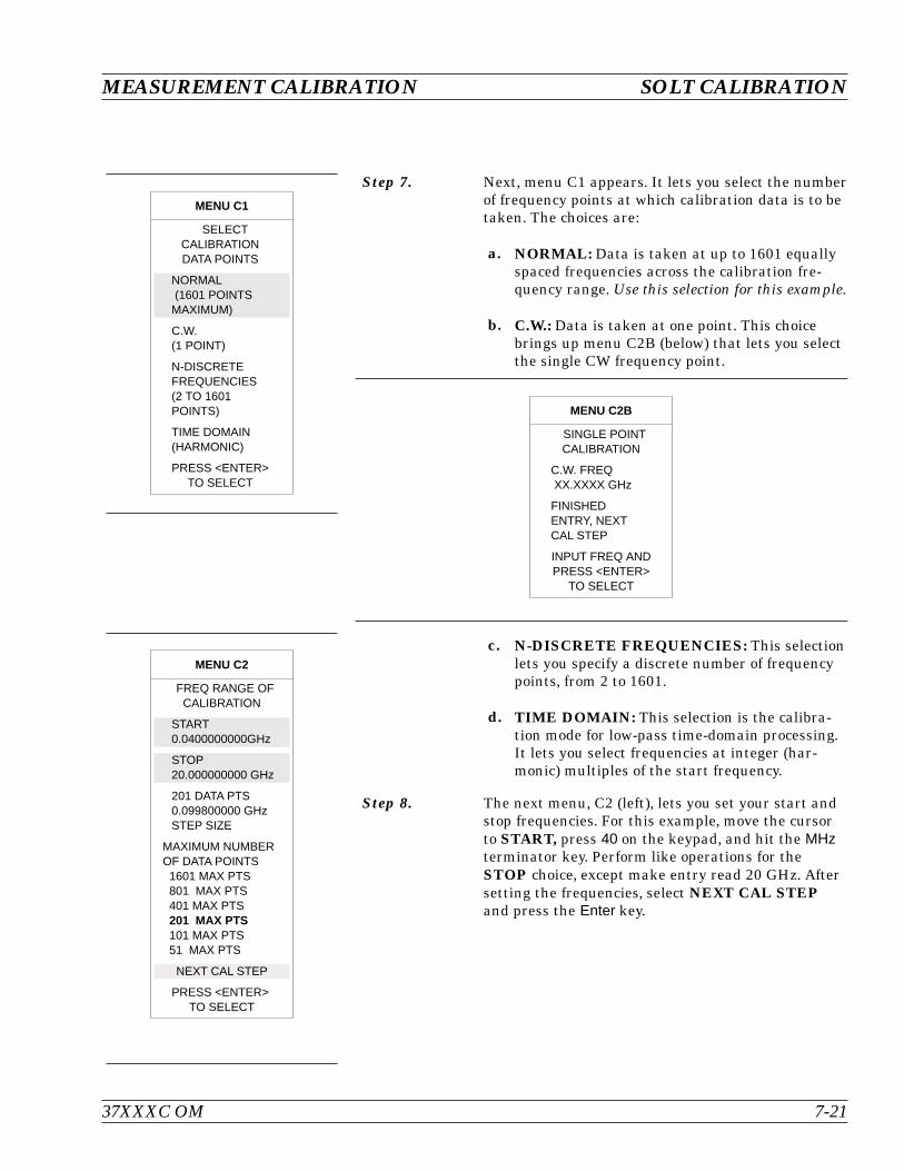
Step 7. Next, menu C1 appears. It lets you select the numberof frequency points at which calibration data is to betaken. The choices are:
a. NORMAL: Data is taken at up to 1601 equallyspaced frequencies across the calibration fre-quency range. Use this selection for this example.
b. C.W.: Data is taken at one point. This choicebrings up menu C2B (below) that lets you selectthe single CW frequency point.
c. N-DISCRETE FREQUENCIES: This selectionlets you specify a discrete number of frequencypoints, from 2 to 1601.
d. TIME DOMAIN: This selection is the calibra-tion mode for low-pass time-domain processing.It lets you select frequencies at integer (har-monic) multiples of the start frequency.
Step 8. The next menu, C2 (left), lets you set your start andstop frequencies. For this example, move the cursorto START, press 40 on the keypad, and hit the MHzterminator key. Perform like operations for theSTOP choice, except make entry read 20 GHz. Aftersetting the frequencies, select NEXT CAL STEPand press the Enter key.
37XXXC OM 7-21
MEASUREMENT CALIBRATION SOLT CALIBRATION
MENU C1
SELECTCALIBRATIONDATA POINTS
NORMAL(1601 POINTSMAXIMUM)
C.W.(1 POINT)
N-DISCRETEFREQUENCIES(2 TO 1601POINTS)
TIME DOMAIN(HARMONIC)
PRESS <ENTER>TO SELECT
MENU C2
FREQ RANGE OFCALIBRATION
START0.0400000000GHz
STOP20.000000000 GHz
201 DATA PTS0.099800000 GHzSTEP SIZE
MAXIMUM NUMBEROF DATA POINTS1601 MAX PTS801 MAX PTS401 MAX PTS201 MAX PTS101 MAX PTS51 MAX PTS
NEXT CAL STEP
PRESS <ENTER>TO SELECT
MENU C2B
SINGLE POINTCALIBRATION
C.W. FREQXX.XXXX GHz
FINISHEDENTRY, NEXTCAL STEP
INPUT FREQ ANDPRESS <ENTER>
TO SELECT
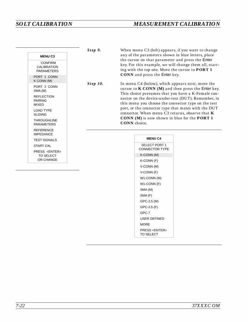
Step 9. When menu C3 (left) appears, if you want to changeany of the parameters shown in blue letters, placethe cursor on that parameter and press the Enterkey. For this example, we will change them all, start-ing with the top one. Move the cursor to PORT 1CONN and press the Enter key.
Step 10. In menu C4 (below), which appears next, move thecursor to K CONN (M) and then press the Enter key.This choice presumes that you have a K-Female con-nector on the device-under-test (DUT). Remember, inthis menu you choose the connector type on the testport, or the connector type that mates with the DUTconnector. When menu C3 returns, observe that KCONN (M) is now shown in blue for the PORT 1CONN choice.
SOLT CALIBRATION MEASUREMENT CALIBRATION
7-22 37XXXC OM
MENU C3
CONFIRMCALIBRATIONPARAMETERS
PORT 1 CONNK CONN (M)
PORT 2 CONNSMA (M)
REFLECTIONPAIRINGMIXED
LOAD TYPESLIDING
THROUGHLINEPARAMETERS
REFERENCEIMPEDANCE
TEST SIGNALS
START CAL
PRESS <ENTER>TO SELECTOR CHANGE
MENU C4
SELECT PORT 1CONNECTOR TYPE
K-CONN (M)
K-CONN (F)
V-CONN (M)
V-CONN (F)
W1-CONN (M)
W1-CONN (F)
SMA (M)
SMA (F)
GPC-3.5 (M)
GPC-3.5 (F)
GPC-7
USER DEFINED
MORE
PRESS <ENTER>TO SELECT
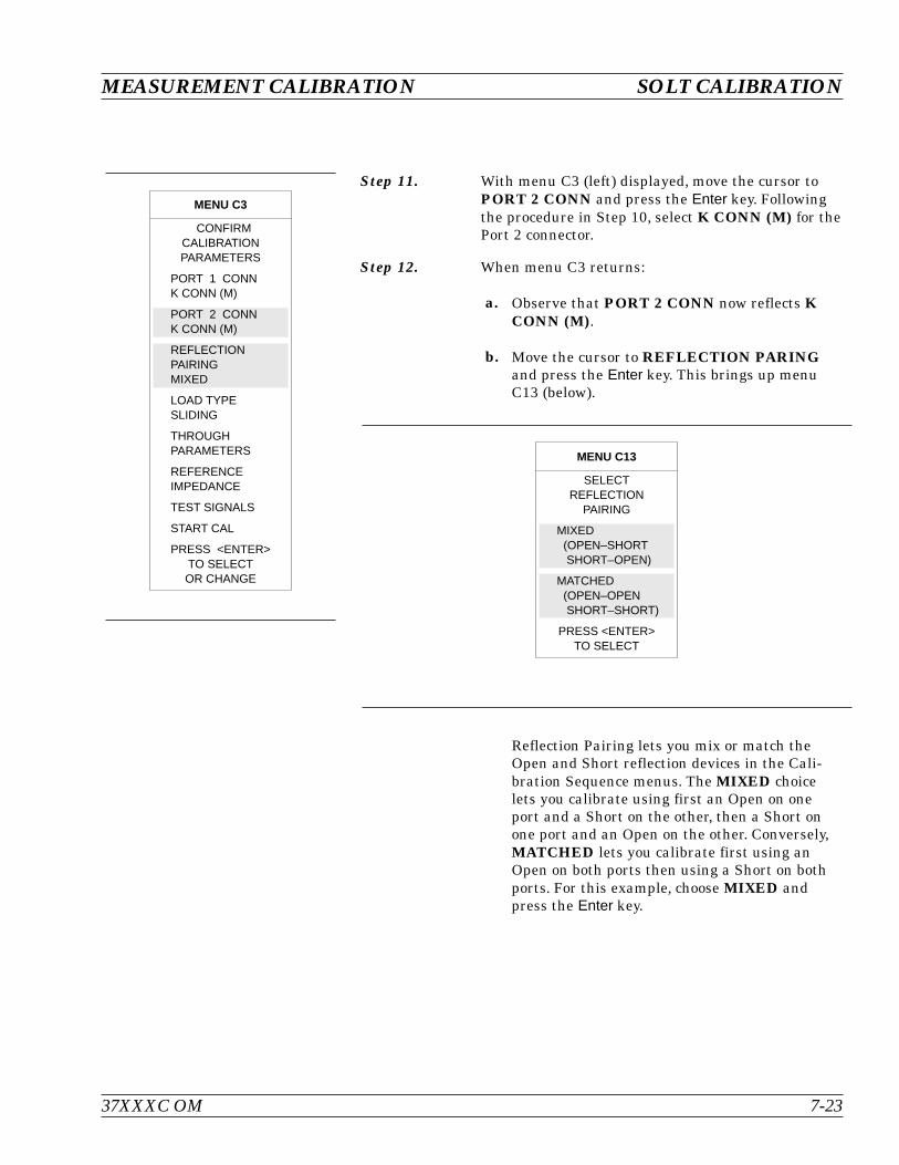
Step 11. With menu C3 (left) displayed, move the cursor toPORT 2 CONN and press the Enter key. Followingthe procedure in Step 10, select K CONN (M) for thePort 2 connector.
Step 12. When menu C3 returns:
a. Observe that PORT 2 CONN now reflects KCONN (M).
b. Move the cursor to REFLECTION PARINGand press the Enter key. This brings up menuC13 (below).
Reflection Pairing lets you mix or match theOpen and Short reflection devices in the Cali-bration Sequence menus. The MIXED choicelets you calibrate using first an Open on oneport and a Short on the other, then a Short onone port and an Open on the other. Conversely,MATCHED lets you calibrate first using anOpen on both ports then using a Short on bothports. For this example, choose MIXED andpress the Enter key.
37XXXC OM 7-23
MEASUREMENT CALIBRATION SOLT CALIBRATION
MENU C3
CONFIRMCALIBRATIONPARAMETERS
PORT 1 CONNK CONN (M)
PORT 2 CONNK CONN (M)
REFLECTIONPAIRINGMIXED
LOAD TYPESLIDING
THROUGHPARAMETERS
REFERENCEIMPEDANCE
TEST SIGNALS
START CAL
PRESS <ENTER>TO SELECTOR CHANGE
MENU C13
SELECTREFLECTION
PAIRING
MIXED(OPEN–SHORTSHORT–OPEN)
MATCHED(OPEN–OPENSHORT–SHORT)
PRESS <ENTER>TO SELECT
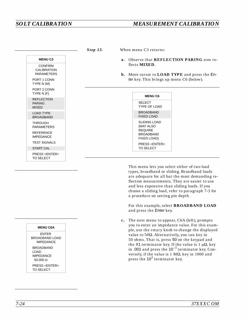
Step 13. When menu C3 returns:
a. Observe that REFLECTION PARING now re-flects MIXED.
b. Move cursor to LOAD TYPE and press the En-ter key. This brings up menu C6 (below).
This menu lets you select either of two loadtypes, broadband or sliding. Broadband loadsare adequate for all but the most demanding re-flection measurements. They are easier to useand less expensive than sliding loads. If youchoose a sliding load, refer to paragraph 7-3 fora procedure on setting pin depth.
For this example, select BROADBAND LOADand press the Enter key.
c. The next menu to appear, C6A (left), promptsyou to enter an impedance value. For this exam-ple, use the rotary knob to change the displayedvalue to 50. Alternatively, you can key in50 ohms. That is, press 50 on the keypad andthe X1 terminator key. If the value is 1 , keyin .001 and press the 10–3 terminator key. Con-versely, if the value is 1 M, key in 1000 andpress the 103 terminator key.
SOLT CALIBRATION MEASUREMENT CALIBRATION
7-24 37XXXC OM
MENU C6
SELECTTYPE OF LOAD
BROADBANDFIXED LOAD
SLIDING LOAD(MAY ALSOREQUIREBROADBANDFIXED LOAD)
PRESS <ENTER>TO SELECT
MENU C3
CONFIRMCALIBRATIONPARAMETERS
PORT 1 CONNTYPE N (M)
PORT 2 CONNTYPE N (F)
REFLECTIONPARINGMIXED
LOAD TYPEBROADBAND
THROUGHPARAMETERS
REFERENCEIMPEDANCE
TEST SIGNALS
START CAL
PRESS <ENTER>TO SELECT
MENU C6A
ENTERBROADBAND LOAD
IMPEDANCE
BROADBANDLOADIMPEDANCE50.000
PRESS <ENTER>TO SELECT

Step 14. When menu C3 again returns:
a. Observe that LOAD TYPE now showsBROADBAND.
b. Move cursor to THROUGH PARAMETERSand press the Enter key.
Step 15. Menu C20 (left) appears next. It lets you define thelength of the offset and the impedance of thethroughline. For this example, enter 0 mm for lengthand 50 ohms for impedance.
Step 16. When menu C3 reappears, move the cursor to REF-ERENCE IMPEDANCE and press the Enter key.This brings up menu C17 (left).
Step 17. Move cursor to REFERENCE IMPEDANCE anduse the rotary knob to change the displayed value to50.
Press the Enter key when you have completed yourvalue entry.
37XXXC OM 7-25
MEASUREMENT CALIBRATION SOLT CALIBRATION
MENU C20
ENTERTHROUGH LINEPARAMETERS
OFFSET LENGTH0.0000 mm
THROUGHLINEIMPEDANCE
50.000
PRESS <ENTER>WHEN COMPLETE
MENU C17
ENTERREFERENCEIMPEDANCE
REFERENCEIMPEDANCE
50.000
PRESS <ENTER>WHEN COMPLETE

Step 18. When menu C3 returns, select TEST SIGNALS tobring up menu SU2 (left).
Step 19. Menu SU2 lets you define the power level of the sig-nals at the two test ports. Power delivered to theDUT by the test set must be such that the measuredsignals are well above the noise floor but below the0.1 dB compression level of the Test Set samplers.(Noise floor and maximum signal into Port 2 levelsare specified in Appendix C.)
For measuring high power signals, a Port 2 attenu-ator in the forward transmission path allows up to1 Watt of power (30 dBm) before 0.1 dB compressionoccurs.
Determine the required input power level and theexpected output RF power level from the DUT.Ideally, the Port 2 step attenuator should be set sothat the input to the test sampler (left) is less than–10 dBm. For example, if the input to the DUT is setfor –20 dBm and the device gain is 40 dB, set thePORT 2 ATTN menu option for 20 dB.
(If you needed to calibrate the test port for powerflatness, you would move the cursor to FLATNESSCORRECTION and press the Enter key.)
Finally, move the cursor to PREVIOUS MENU andpress the Enter key. This returns you to menu SU1.When you get there, press the Enter key to return tomenu C3.
SOLT CALIBRATION MEASUREMENT CALIBRATION
7-26 37XXXC OM
MENU SU2
TEST SIGNALS
POWER CONTROL0.0 dB(0 TO -20)
PORT 1 ATTN20 dB (0 - 70)
PORT 1 POWERXX.XX dBm
PORT 2 ATTNX0 dB (0-40)
CALIBRATEFOR FLATNESS(CAL EXISTS)
FLATNESSCORRECTIONAT XX.X dBm
SOURCE 2 PWRXX.X dBm
PREVIOUS MENU
PRESS <ENTER>TO SELECT
TB
Sampler0 to 40 dB
P2
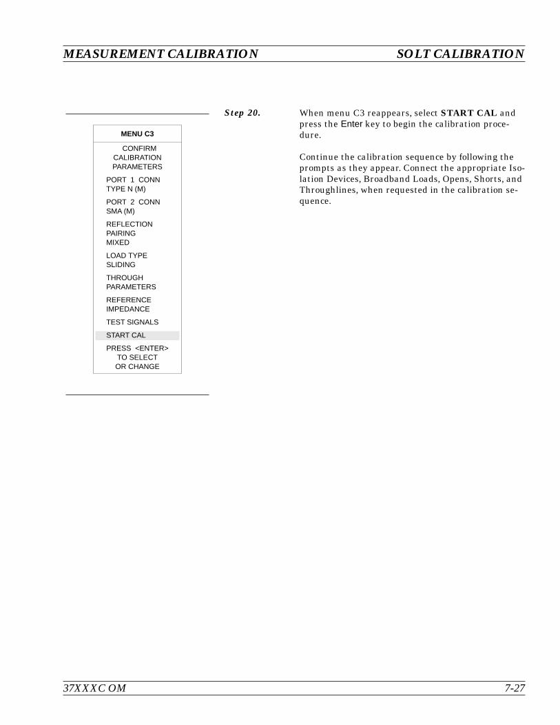
Step 20. When menu C3 reappears, select START CAL andpress the Enter key to begin the calibration proce-dure.
Continue the calibration sequence by following theprompts as they appear. Connect the appropriate Iso-lation Devices, Broadband Loads, Opens, Shorts, andThroughlines, when requested in the calibration se-quence.
37XXXC OM 7-27
MEASUREMENT CALIBRATION SOLT CALIBRATION
MENU C3
CONFIRMCALIBRATIONPARAMETERS
PORT 1 CONNTYPE N (M)
PORT 2 CONNSMA (M)
REFLECTIONPAIRINGMIXED
LOAD TYPESLIDING
THROUGHPARAMETERS
REFERENCEIMPEDANCE
TEST SIGNALS
START CAL
PRESS <ENTER>TO SELECTOR CHANGE
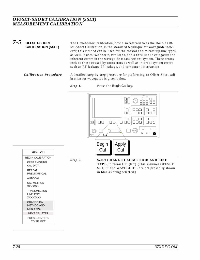
7-5 OFFSET-SHORTCALIBRATION (SSLT)
The Offset-Short calibration, now also referred to as the Double Off-set-Short Calibration, is the standard technique for waveguide; how-ever, this method can be used for the coaxial and microstrip line typesas well. It uses two shorts, two loads, and a thru line to categorize theinherent errors in the waveguide measurement system. These errorsinclude those caused by connectors as well as internal system errorssuch as RF leakage, IF leakage, and component interaction.
Calibration Procedure A detailed, step-by-step procedure for performing an Offset-Short cali-bration for waveguide is given below.
Step 1. Press the Begin Cal key.
Step 2. Select CHANGE CAL METHOD AND LINETYPE, in menu C11 (left). (This assumes OFFSETSHORT and WAVEGUIDE are not presently shownin blue as being selected.)
OFFSET-SHORT CALIBRATION (SSLT)MEASUREMENT CALIBRATION
7-28 37XXXC OM
ApplyCal
BeginCal
MENU C11
BEGIN CALIBRATION
KEEP EXISTINGCAL DATA
REPEATPREVIOUS CAL
AUTOCAL
CAL METHODXXXXXXX
TRANSMISSIONLINE TYPE:XXXXXXXX
CHANGE CALMETHOD ANDLINE TYPE
NEXT CAL STEP
PRESS <ENTER>TO SELECT
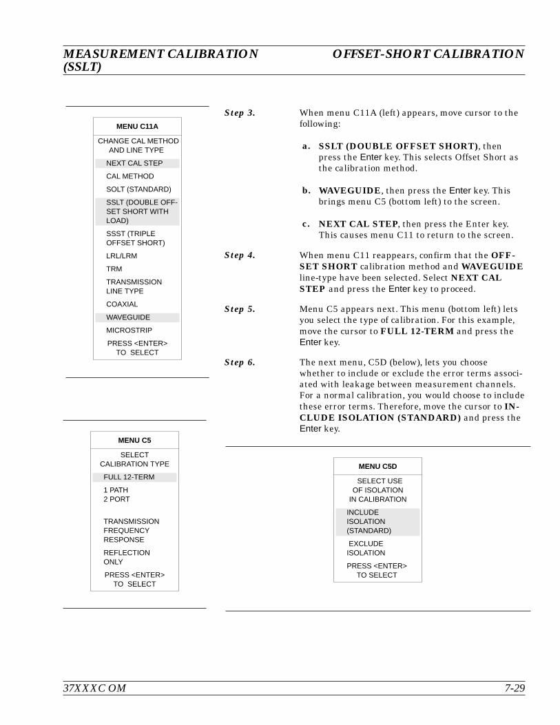
Step 3. When menu C11A (left) appears, move cursor to thefollowing:
a. SSLT (DOUBLE OFFSET SHORT), thenpress the Enter key. This selects Offset Short asthe calibration method.
b. WAVEGUIDE, then press the Enter key. Thisbrings menu C5 (bottom left) to the screen.
c. NEXT CAL STEP, then press the Enter key.This causes menu C11 to return to the screen.
Step 4. When menu C11 reappears, confirm that the OFF-SET SHORT calibration method and WAVEGUIDEline-type have been selected. Select NEXT CALSTEP and press the Enter key to proceed.
Step 5. Menu C5 appears next. This menu (bottom left) letsyou select the type of calibration. For this example,move the cursor to FULL 12-TERM and press theEnter key.
Step 6. The next menu, C5D (below), lets you choosewhether to include or exclude the error terms associ-ated with leakage between measurement channels.For a normal calibration, you would choose to includethese error terms. Therefore, move the cursor to IN-CLUDE ISOLATION (STANDARD) and press theEnter key.
37XXXC OM 7-29
MEASUREMENT CALIBRATION OFFSET-SHORT CALIBRATION(SSLT)
MENU C11A
CHANGE CAL METHODAND LINE TYPE
NEXT CAL STEP
CAL METHOD
SOLT (STANDARD)
SSLT (DOUBLE OFF-SET SHORT WITHLOAD)
SSST (TRIPLEOFFSET SHORT)
LRL/LRM
TRM
TRANSMISSIONLINE TYPE
COAXIAL
WAVEGUIDE
MICROSTRIP
PRESS <ENTER>TO SELECT
MENU C5
SELECTCALIBRATION TYPE
FULL 12-TERM
1 PATH2 PORT
TRANSMISSIONFREQUENCYRESPONSE
REFLECTIONONLY
PRESS <ENTER>TO SELECT
MENU C5D
SELECT USEOF ISOLATION
IN CALIBRATION
INCLUDEISOLATION(STANDARD)
EXCLUDEISOLATION
PRESS <ENTER>TO SELECT

Step 7. Menu C1 (left), which appears next, lets you selectthe number of frequency points at which calibrationdata is to be taken. Of these choices, which were de-scribed in paragraph 7-4, choose NORMAL (1601POINTS MAXIMUM) for this example.
Step 8. The next menu, C2 (below), lets you set your startand stop frequencies. For this example, move cursorto START, press 40 on keypad, and press the MHzterminator key. Perform like operations for theSTOP choice, except make entry read 20 GHz. Aftersetting the frequencies, select NEXT CAL STEPand press the Enter key.
Step 9. When menu C3B (bottom left) appears, if you wantto change any of the parameters shown in blue let-ters, place the cursor on that parameter and pressthe Enter key. (These choices operate the same aswas described for menu C3 in paragraph 7-4.) Forthis example, we change the waveguide parameters.Move the cursor to WAVEGUIDE PARAMETERSand press the Enter key.
OFFSET-SHORT CALIBRATION (SSLT)MEASUREMENT CALIBRATION
7-30 37XXXC OM
MENU C1
SELECTCALIBRATIONDATA POINTS
NORMAL(1601 POINTSMAXIMUM)
C.W.(1 POINT)
N-DISCRETEFREQUENCIES(2 TO 1601POINTS)
TIME DOMAIN(HARMONIC)
PRESS <ENTER>TO SELECT
MENU C2
FREQ RANGE OFCALIBRATION
START0.0400000000GHz
STOP20.000000000 GHz
201 DATA PTS0.099800000 GHzSTEP SIZE
MAXIMUM NUMBEROF DATA POINTS1601 MAX PTS801 MAX PTS401 MAX PTS201 MAX PTS101 MAX PTS51 MAX PTS
NEXT CAL STEP
PRESS <ENTER>TO SELECT
MENU C3B
CONFIRMCALIBRATIONPARAMETERS
WAVEGUIDEPARAMETERSINSTALLED
REFLECTIONPAIRINGXXXXXXXX
LOAD TYPEBROADBAND
THROUGH LINEPARAMETERS
TEST SIGNALS
START CAL
PRESS <ENTER>TO SELECTOR CHANGE

Step 10. When menu C15 (left) appears, move cursor to one ofthe two available choices and press the Enter key.These choices are described below.
a. USE INSTALLED WAVEGUIDE KIT: Se-lecting this choice uses the values shown in bluefor IDENTIFIER, CUTOFF FREQ, SHORT 1,and SHORT 2. Select this choice, for this exam-ple.
b. USER DEFINED: Selecting this choice bringsup menu C15A (below), which lets you specifywaveguide parameters. After defining yourwaveguide parameters, you are returned tomenu C3B.
Step 11. Continue the calibration sequence by following theprompts as they appear. Connect the appropriate Iso-lation Devices, Broadband Loads, Shorts, andThroughlines, when requested in the calibration se-quence.
37XXXC OM 7-31
MEASUREMENT CALIBRATION OFFSET-SHORT CALIBRATION(SSLT)
MENU C15
SELECTWAVEGUIDEKIT TO USE
–INSTALLED KIT—
IDENTIFIERXXXX
CUTOFF FREQ:XXX.XXXXXXXXX GHz
SHORT 1XX.XXXX mm
SHORT 2XX.XXXX mm
USE INSTALLEDWAVEGUIDE KIT
USER DEFINED
PRESS <ENTER>TO SELECT
MENU C15A
ENTERWAVEGUIDE
PARAMETERS
WAVEGUIDECUTOFF FREQ:XXX.XXXXXXXXX GHz
OFFSET LENGTHOF SHORT 1XX.XXXX mm
OFFSET LENGTHOF SHORT 2XX.XXXX mm
PRESS <ENTER>WHEN COMPLETE
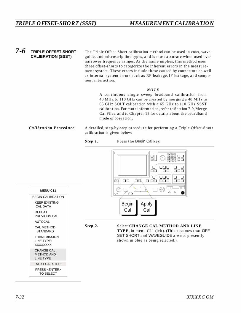
7-6 TRIPLE OFFSET-SHORTCALIBRATION (SSST)
The Triple Offset-Short calibration method can be used in coax, wave-guide, and microstrip line types, and is most accurate when used overnarrower frequency ranges. As the name implies, this method usesthree offset-shorts to categorize the inherent errors in the measure-ment system. These errors include those caused by connectors as wellas internal system errors such as RF leakage, IF leakage, and compo-nent interaction.
NOTEA continuous single sweep bradband calibration from40 MHz to 110 GHz can be created by merging a 40 MHz to65 GHz SOLT calibration with a 65 GHz to 110 GHz SSSTcalibration.For more information, refer to Section 7-9,MergeCal Files, and to Chapter 15 for details about the broadbandmode of operation.
Calibration Procedure A detailed, step-by-step procedure for performing a Triple Offset-Shortcalibration is given below:
Step 1. Press the Begin Cal key.
Step 2. Select CHANGE CAL METHOD AND LINETYPE, in menu C11 (left). (This assumes that OFF-SET SHORT and WAVEGUIDE are not presentlyshown in blue as being selected.)
TRIPLE OFFSET-SHORT (SSST) MEASUREMENT CALIBRATION
7-32 37XXXC OM
MENU C11
BEGIN CALIBRATION
KEEP EXISTINGCAL DATA
REPEATPREVIOUS CAL
AUTOCAL
CAL METHODSTANDARD
TRANSMISSIONLINE TYPE:XXXXXXXX
CHANGE CALMETHOD ANDLINE TYPE
NEXT CAL STEP
PRESS <ENTER>TO SELECT
ApplyCal
BeginCal

Step 3. When menu C11A (left) appears, move cursor to thefollowing:
a. SSST (TRIPLE OFFSET SHORT), then pressthe Enter key. This selects Triple Offset-Short asthe calibration method.
b. COAXIAL, then press the Enter key. This bringsmenu C5 (left) to the screen.
c. NEXT CAL STEP, then press the Enter key.This causes menu C11 to return to the screen.
Step 4. When menu C11 reappears, confirm that the SSSTcalibration method and COAXIAL line-type havebeen selected. Select NEXT CAL STEP and pressthe Enter key to proceed.
Step 5. Menu C5 appears next (lower left). This menu letsyou select the type of calibration. For this example,move the cursor to FULL 12-TERM and press theEnter key.
Step 6. The next menu, C5D (below), lets you choosewhether to include or exclude the error terms associ-ated with leakage between measurement channels.For a normal calibration, you would choose to includethese error terms. Therefore, move the cursor toINCLUDE ISOLATION (STANDARD) and pressthe Enter key.
37XXXC OM 7-33
MEASUREMENT CALIBRATION TRIPLE OFFSET-SHORT (SSST)
MENU C11A
CHANGE CAL METHODAND LINE TYPE
NEXT CAL STEP
CAL METHOD
SOLT (STANDARD)
SSLT (DOUBLE OFF-SET SHORT WITHLOAD)
SSST (TRIPLE OFFSETSHORT)
LRL/LRM
TRM
TRANSMISSIONLINE TYPE
COAXIAL
WAVEGUIDE
MICROSTRIP
PRESS <ENTER>TO SELECT
Menu C5
CALIBRATIONTYPE
FULL 12-TERM
1 PATH2 PORT
TRANSMISSIONFREQUENCYRESPONSE
REFLECTION ONLY
PRESS <ENTER>TO SELECT
Menu C5D
SELECT USEOF ISLOATIONIN CALIBRATION
INCLUDEISOLATION(STANDARD)
EXCLUDEISOLATION
PRESS <ENTER>TO SELECT
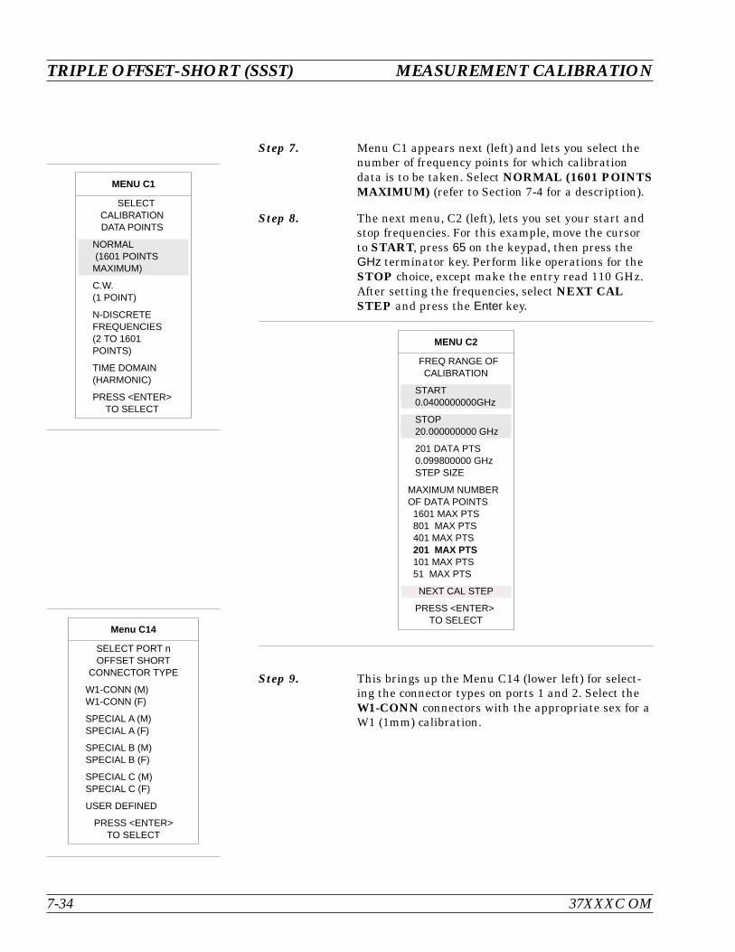
Step 7. Menu C1 appears next (left) and lets you select thenumber of frequency points for which calibrationdata is to be taken. Select NORMAL (1601 POINTSMAXIMUM) (refer to Section 7-4 for a description).
Step 8. The next menu, C2 (left), lets you set your start andstop frequencies. For this example, move the cursorto START, press 65 on the keypad, then press theGHz terminator key. Perform like operations for theSTOP choice, except make the entry read 110 GHz.After setting the frequencies, select NEXT CALSTEP and press the Enter key.
Step 9. This brings up the Menu C14 (lower left) for select-ing the connector types on ports 1 and 2. Select theW1-CONN connectors with the appropriate sex for aW1 (1mm) calibration.
TRIPLE OFFSET-SHORT (SSST) MEASUREMENT CALIBRATION
7-34 37XXXC OM
MENU C2
FREQ RANGE OFCALIBRATION
START0.0400000000GHz
STOP20.000000000 GHz
201 DATA PTS0.099800000 GHzSTEP SIZE
MAXIMUM NUMBEROF DATA POINTS1601 MAX PTS801 MAX PTS401 MAX PTS201 MAX PTS101 MAX PTS51 MAX PTS
NEXT CAL STEP
PRESS <ENTER>TO SELECT
MENU C1
SELECTCALIBRATIONDATA POINTS
NORMAL(1601 POINTSMAXIMUM)
C.W.(1 POINT)
N-DISCRETEFREQUENCIES(2 TO 1601POINTS)
TIME DOMAIN(HARMONIC)
PRESS <ENTER>TO SELECT
Menu C14
SELECT PORT nOFFSET SHORT
CONNECTOR TYPE
W1-CONN (M)W1-CONN (F)
SPECIAL A (M)SPECIAL A (F)
SPECIAL B (M)SPECIAL B (F)
SPECIAL C (M)SPECIAL C (F)
USER DEFINED
PRESS <ENTER>TO SELECT

Step 10. When menu C3B (left) appears, if you want tochange any of the parameters shown in blue letters,place the cursor on that parameter and press the En-ter key.
Step 11. When menu C3 (lower left) returns:
a. Observe that PORT 1 CONN andPORT 2 CONN now reflects W1 CONN (M).
b. Move the cursor to REFLECTION PARINGand press the Enter key. This brings up menuC13 (below).
Step 12. Reflection Pairing lets you mix or match Offset Shortdevices in the Calibration Sequence menus, as perthe kit available. Generally, on-wafer calibration sub-strates have matched components; however, it ismore convenient, on a coaxial calibration, to useMIXED pairing in the case of the same connectortypes on both ports. The MIXED choice lets you cali-brate using different offset shorts on the two ports.Conversely, MATCHED pairing lets you calibrate insequence using one offset short type in each step. Forthis example, choose MIXED and press the Enterkey.
Step 13. When menu C3 reappears, confirm the calibrationparameters selected for the calibration, then selectSTART CAL and continue the calibration sequenceby following the prompts as they appear.
Step 14. Connect the appropriate Isolation Devices, the threeOffset Shorts, and the Throughlines when requestedin the calibration sequence.
37XXXC OM 7-35
MEASUREMENT CALIBRATION TRIPLE OFFSET-SHORT (SSST)
MENU C3B
CONFIRMCALIBRATIONPARAMETERS
WAVEGUIDEPARAMETERSINSTALLED
REFLECTIONPAIRINGMIXED
LOAD TYPEBROADBAND
THROUGH LINEPARAMETERS
TEST SIGNALS
START CAL
PRESS <ENTER>TO SELECTOR CHANGE
MENU C3
CONFIRMCALIBRATIONPARAMETERS
PORT 1 CONNW1-CONN (M)
PORT 2 CONNW1-CONN (M)
REFLECTIONPAIRINGXXXXXXXX
LOAD TYPEBROADBAND
THROUGH LINEPARAMETERS
REFERENCEIMPEDANCE
TEST SIGNALS
START CAL
PRESS <ENTER>TO SELECTOR CHANGE
MENU C13
SELECTREFLECTION
PAIRING
MIXED(SHORT1-SHORT2,SHORT2-SHORT3,SHORT3-SHORT1)
MATCHED(SHORT1-SHORT1,SHORT2-SHORT2,SHORT3-SHORT3)
PRESS <ENTER>TO SELECTOR CHANGE
7-7 LRL/LRM CALIBRATION The LRL/LRM (line-reflect-line/line-reflect-match) calibration* featureprovides an enhanced capability for error compensation when makingmeasurements in coaxial, microstrip and waveguide transmission me-dia. Instead of using the standard Open, Short, and Load, theLRL/LRM calibration method uses two lines and a reflection or match.The difference in length between line 1 and line 2 creates the mea-surements necessary for the error solutions.
The LRL/LRM calibration technique uses the characteristic impedanceof a length of transmission line or a precision match as the calibrationstandard. A full LRL/LRM calibration consists of two transmission linemeasurements, a high reflection measurement, and an isolation mea-surement. Using this technique full 12-term error correction can beperformed with the 37XXXC.
Three-line LRL/LRM calibration can also be selected. In a two-lineLRL measurement, the difference in length between line one and linetwo is necessary for calibration but limits the frequency range to a 9:1span. The use of three lines in the calibration extends the frequencyrange to an 81:1 span. A combination of LRL and LRM can accomodateany broadband measurement.
1. Through the use of LRL/LRM calibration and an external com-puter, in conjunction with ANACAT software, multiple-level de-em-bedding is possible. This calibration allows you to make semi-con-ductor chip measurements up to 40 GHz with a single test fixture.
2. In addition, any non-coaxial transmission media, including mixedmedia interconnects, can be accommodated. For example, a test de-vice with a waveguide input and a coplanar microstrip output canbe measured. Software automatically compensates for themicrostrip dispersion.
A detailed procedure for calibrating for a measurement using theLRL/LRM method is provided in the following pages.
LRL/LRM CALIBRATION MEASUREMENT CALIBRATION
7-36 37XXXC OM
*LRM Calibration Method of Rhode & Scharwz, Germany
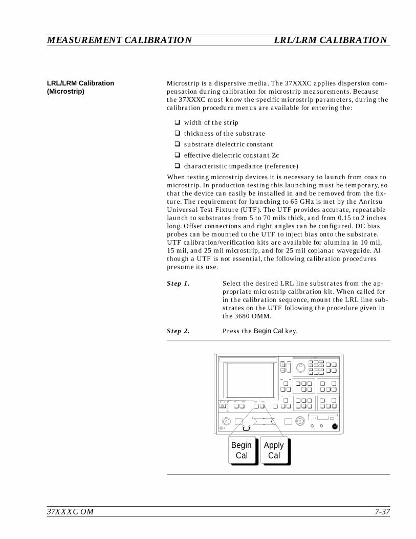
LRL/LRM Calibration(Microstrip)
Microstrip is a dispersive media. The 37XXXC applies dispersion com-pensation during calibration for microstrip measurements. Becausethe 37XXXC must know the specific microstrip parameters, during thecalibration procedure menus are available for entering the:
width of the strip
thickness of the substrate
substrate dielectric constant
effective dielectric constant Zc
characteristic impedance (reference)
When testing microstrip devices it is necessary to launch from coax tomicrostrip. In production testing this launching must be temporary, sothat the device can easily be installed in and be removed from the fix-ture. The requirement for launching to 65 GHz is met by the AnritsuUniversal Test Fixture (UTF). The UTF provides accurate, repeatablelaunch to substrates from 5 to 70 mils thick, and from 0.15 to 2 incheslong. Offset connections and right angles can be configured. DC biasprobes can be mounted to the UTF to inject bias onto the substrate.UTF calibration/verification kits are available for alumina in 10 mil,15 mil, and 25 mil microstrip, and for 25 mil coplanar waveguide. Al-though a UTF is not essential, the following calibration procedurespresume its use.
Step 1. Select the desired LRL line substrates from the ap-propriate microstrip calibration kit. When called forin the calibration sequence, mount the LRL line sub-strates on the UTF following the procedure given inthe 3680 OMM.
Step 2. Press the Begin Cal key.
37XXXC OM 7-37
MEASUREMENT CALIBRATION LRL/LRM CALIBRATION
ApplyCal
BeginCal
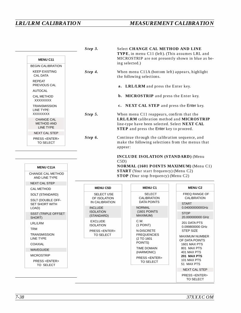
Step 3. Select CHANGE CAL METHOD AND LINETYPE, in menu C11 (left). (This assumes LRL andMICROSTRIP are not presently shown in blue as be-ing selected.)
Step 4. When menu C11A (bottom left) appears, highlightthe following selections.
a. LRL/LRM and press the Enter key.
b. MICROSTRIP and press the Enter key.
c. NEXT CAL STEP and press the Enter key.
Step 5. When menu C11 reappears, confirm that theLRL/LRM calibration method and MICROSTRIPline-type have been selected. Select NEXT CALSTEP and press the Enter key to proceed.
Step 6. Continue through the calibration sequence, andmake the following selections from the menus thatappear:
INCLUDE ISOLATION (STANDARD) (MenuC5D)NORMAL (1601 POINTS MAXIMUM) (Menu C1)START (Your start frequency) (Menu C2)STOP (Your stop frequency) (Menu C2)
LRL/LRM CALIBRATION MEASUREMENT CALIBRATION
7-38 37XXXC OM
MENU C11
BEGIN CALIBRATION
KEEP EXISTINGCAL DATA
REPEATPREVIOUS CAL
AUTOCAL
CAL METHODXXXXXXXX
TRANSMISSIONLINE TYPE:XXXXXXXX
CHANGE CALMETHOD AND
LINE TYPE
NEXT CAL STEP
PRESS <ENTER>TO SELECT
MENU C11A
CHANGE CAL METHODAND LINE TYPE
NEXT CAL STEP
CAL METHOD
SOLT (STANDARD)
SSLT (DOUBLE OFF-SET SHORT WITHLOAD)
SSST (TRIPLE OFFSETSHORT)
LRL/LRM
TRM
TRANSMISSIONLINE TYPE
COAXIAL
WAVEGUIDE
MICROSTRIP
PRESS <ENTER>TO SELECT
MENU C5D
SELECT USEOF ISOLATION
IN CALIBRATION
INCLUDEISOLATION(STANDARD)
EXCLUDEISOLATION
PRESS <ENTER>TO SELECT
MENU C1
SELECTCALIBRATIONDATA POINTS
NORMAL(1601 POINTSMAXIMUM)
C.W.(1 POINT)
N-DISCRETEFREQUENCIES(2 TO 1601POINTS)
TIME DOMAIN(HARMONIC)
PRESS <ENTER>TO SELECT
MENU C2
FREQ RANGE OFCALIBRATION
START0.0400000000GHz
STOP20.000000000 GHz
201 DATA PTS0.099800000 GHzSTEP SIZE
MAXIMUM NUMBEROF DATA POINTS1601 MAX PTS801 MAX PTS401 MAX PTS201 MAX PTS101 MAX PTS51 MAX PTS
NEXT CAL STEP
PRESS <ENTER>TO SELECT

Step 7. When menu C3G appears, if you want to changemicrostrip parameters to be different from thoseshown in blue, place the cursor on MICROSTRIPPARAMETERS and press the Enter key.
Step 8. When menu C16 (left) appears, move the cursor tothe Anritsu 3680 UTF calibration kit you wish to useor to USER DEFINED; then press the Enter key.
The calibration kit selections shown in menu C16are for the following 3680 Connection SubstrateKits:10 MIL KIT — 36804B-10M15 MIL KIT — 36804B-15M25 MIL KIT — 36804B-25M
If you choose USER DEFINED, the next menu thatappears (C16A), lets you characterize your parame-ters. Move the cursor to each selection, key in avalue, then press the Enter key to return to menuC16.
37XXXC OM 7-39
MEASUREMENT CALIBRATION LRL/LRM CALIBRATION
MENU C3G
CONFIRMCALIBRATIONPARAMETERS
LRL/LRMPARAMETERS
MICROSTRIPPARAMETERSUSER DEFINED
TEST SIGNALS
START CAL
PRESS <ENTER>TO SELECTOR CHANGE
MENU C16
SELECTMICROSTRIPKIT TO USE
10 MIL KIT
15 MIL KIT
25 MIL KIT
USER DEFINED
PRESS <ENTER>WHEN COMPLETE
MENU C16A
ENTERMICROSTRIPPARAMETERS
WIDTH OFSTRIPXX.XXXX mm
THICKNESS OFSUBSTRATEXXXX.XXXX mm
ZcXXX.XXX p
SUBSTRATEDIELECTRICXX.XX
EFFECTIVEDIELECTRICXX.XX(RECOMMENDED0.00)
PRESS <ENTER>WHEN COMPLETE
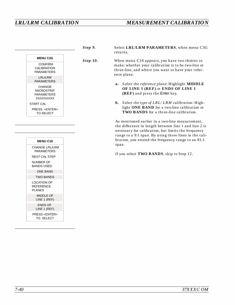
Step 9. Select LRL/LRM PARAMETERS, when menu C3Greturns.
Step 10. When menu C18 appears, you have two choices tomake: whether your calibration is to be two-line orthree-line, and where you want to have your refer-ence plane.
a. Select the reference plane: Highlight MIDDLEOF LINE 1 (REF) or ENDS OF LINE 1(REF) and press the Enter key.
b. Select the type of LRL/LRM calibration: High-light ONE BAND for a two-line calibration orTWO BANDS for a three-line calibration.
As mentioned earlier in a two-line measurement,the difference in length between line 1 and line 2 isnecessary for calibration, but limits the frequencyrange to a 9:1 span. By using three lines in the cali-bration, you extend the frequency range to an 81:1span.
If you select TWO BANDS, skip to Step 12.
LRL/LRM CALIBRATION MEASUREMENT CALIBRATION
7-40 37XXXC OM
MENU C18
CHANGE LRL/LRMPARAMETERS
NEXT CAL STEP
NUMBER OFBANDS USED
ONE BAND
TWO BANDS
LOCATION OFREFERENCEPLANES
MIDDLE OFLINE 1 (REF)
ENDS OFLINE 1 (REF)
PRESS <ENTER>TO SELECT
MENU C3G
CONFIRMCALIBRATIONPARAMETERS
LRL/LRMPARAMETERS
CHANGEMICROSTRIPPARAMETERSXXXXXXXXX
START CAL
PRESS <ENTER>TO SELECT

Step 11. When menu C18A (left) appears, make the followingselections (for 2-line):
a. Move the cursor to DEVICE 1 LINE 1 (REF)and key in the value.
b. Move the cursor to DEVICE 2 LINE/MATCH.Here you have another decision to make:whether your calibration is to be LRL or LRM.For this selection, the Enter key acts as a toggle.
c. If you toggle such that LINE turns red, thenkey in the value for line 2. This value dependson your frequency range.
d. If you toggle MATCH red, observe thatFULLBAND appears. This indicates that yourreflective device covers the full calibrationrange.
e. When you have made both selections, move thecursor to NEXT CAL STEP and press the Enterkey to produce the next menu. Skip to Step 13.
37XXXC OM 7-41
MEASUREMENT CALIBRATION LRL/LRM CALIBRATION
MENU C18A
CHANGE LRL/LRMPARAMETERS
NEXT CAL STEP
CHARACTERIZECAL DEVICES
DEVICE 1LINE 1 (REF)X.XXXX mm
DEVICE 2LINE /MATCHX.XXXX mm
PRESS <ENTER>TO SELECTOR SWITCH
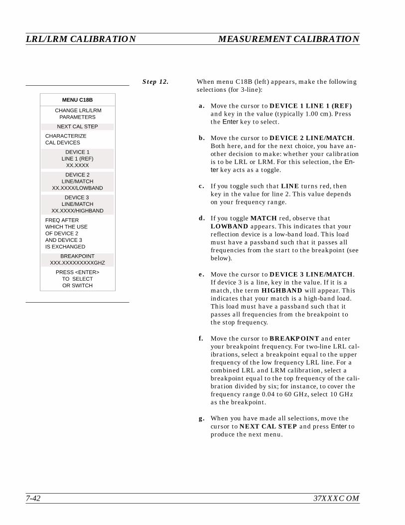
Step 12. When menu C18B (left) appears, make the followingselections (for 3-line):
a. Move the cursor to DEVICE 1 LINE 1 (REF)and key in the value (typically 1.00 cm). Pressthe Enter key to select.
b. Move the cursor to DEVICE 2 LINE/MATCH.Both here, and for the next choice, you have an-other decision to make: whether your calibrationis to be LRL or LRM. For this selection, the En-ter key acts as a toggle.
c. If you toggle such that LINE turns red, thenkey in the value for line 2. This value dependson your frequency range.
d. If you toggle MATCH red, observe thatLOWBAND appears. This indicates that yourreflection device is a low-band load. This loadmust have a passband such that it passes allfrequencies from the start to the breakpoint (seebelow).
e. Move the cursor to DEVICE 3 LINE/MATCH.If device 3 is a line, key in the value. If it is amatch, the term HIGHBAND will appear. Thisindicates that your match is a high-band load.This load must have a passband such that itpasses all frequencies from the breakpoint tothe stop frequency.
f. Move the cursor to BREAKPOINT and enteryour breakpoint frequency. For two-line LRL cal-ibrations, select a breakpoint equal to the upperfrequency of the low frequency LRL line. For acombined LRL and LRM calibration, select abreakpoint equal to the top frequency of the cali-bration divided by six; for instance, to cover thefrequency range 0.04 to 60 GHz, select 10 GHzas the breakpoint.
g. When you have made all selections, move thecursor to NEXT CAL STEP and press Enter toproduce the next menu.
LRL/LRM CALIBRATION MEASUREMENT CALIBRATION
7-42 37XXXC OM
MENU C18B
CHANGE LRL/LRMPARAMETERS
NEXT CAL STEP
CHARACTERIZECAL DEVICES
DEVICE 1LINE 1 (REF)
XX.XXXX
DEVICE 2LINE/MATCH
XX.XXXX/LOWBAND
DEVICE 3LINE/MATCH
XX.XXXX/HIGHBAND
FREQ AFTERWHICH THE USEOF DEVICE 2AND DEVICE 3IS EXCHANGED
BREAKPOINTXXX.XXXXXXXXXGHZ
PRESS <ENTER>TO SELECTOR SWITCH

Step 13. The next menu, C19, gives you choices for your re-flective device.
a. Move the cursor to REFLECTION OFFSETLENGTH and key in a value (typically0.0000 mm).
b. Move the cursor to GREATER THAN Z0 orLESS THAN Z0, depending on whether your re-flective device is an Open or a Short. Press theEnter key to select.
NOTEChoose GREATER THAN Z0 for an Openand LESS THAN Z0 for a Short.
c. When you complete your choices, move the cur-sor to NEXT CAL STEP and press the Enterkey.
Step 14. When menu C3G reappears, move cursor to STARTCAL and press Enter.
Step 15. Continue the calibration sequence by following theprompts as they appear. Mount the appropriate LRLline substrates when requested in the calibration se-quence.
For the REFLECTIVE DEVICE and BROAD-BAND LOAD prompts, remove all substrates fromthe UTF and allow the lower jaws to short the cen-ter conductor. Separate the connector blocks by atleast an inch. (The BROADBAND LOAD promptonly appears if you selected to include isolation inmenu C5B.)
Step 16. Store the calibration.
37XXXC OM 7-43
MEASUREMENT CALIBRATION LRL/LRM CALIBRATION
MENU C19
CHANGE LRL/LRMPARAMETERS
NEXT CAL STEP
REFLECTIONOFFSET LENGTH+XXX.XXXX mm
REFLECTION TYPE
GREATER THAN Zo
LESS THAN Zo
MATCH PARAMETERS
MATCH IMPEDANCE+XXX.XXX
MATCH INDUCTANCE+XXXX.XXXX pH
PRESS <ENTER>TO SELECT
MENU C3G
CONFIRMCALIBRATIONPARAMETERS
CHANGELRL/LRM
PARAMETERS
CHANGEMICROSTRIPPARAMETERSXXXXXXXXX
START CAL
PRESS <ENTER>TO SELECT
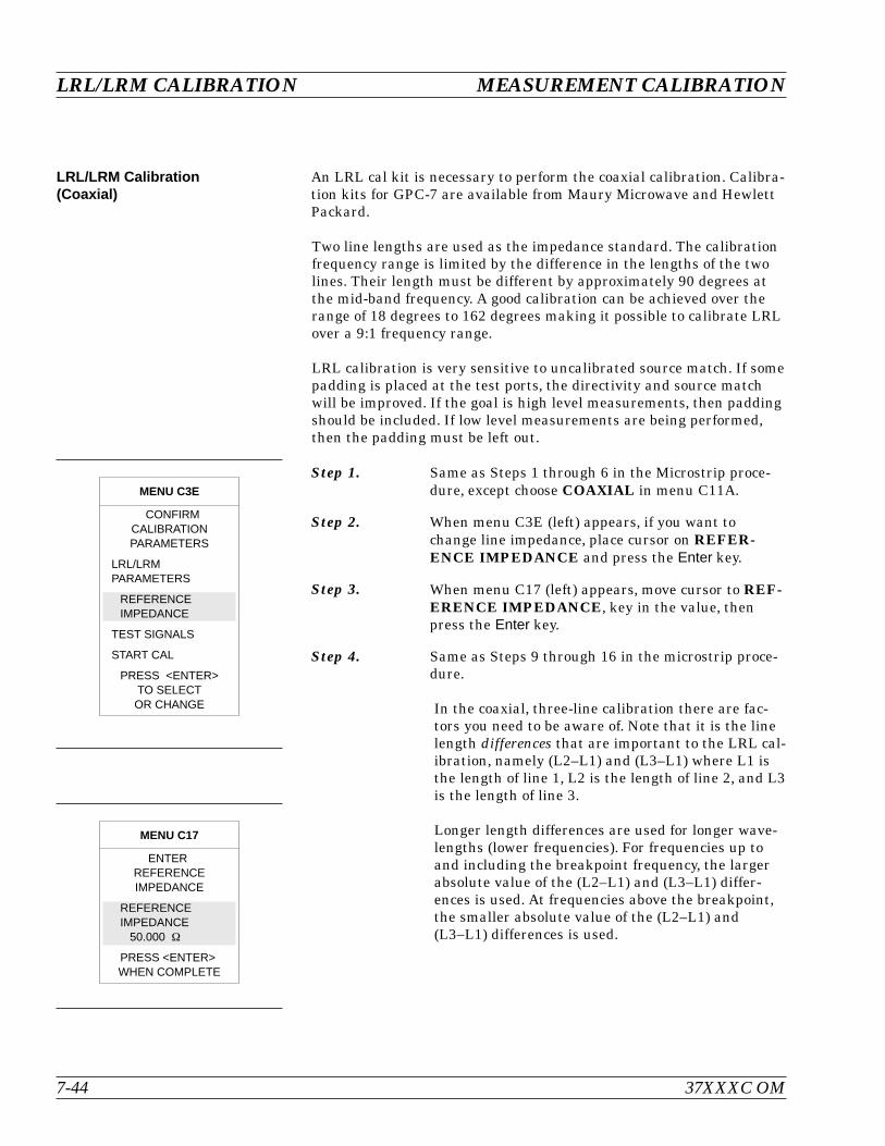
LRL/LRM Calibration(Coaxial)
An LRL cal kit is necessary to perform the coaxial calibration. Calibra-tion kits for GPC-7 are available from Maury Microwave and HewlettPackard.
Two line lengths are used as the impedance standard. The calibrationfrequency range is limited by the difference in the lengths of the twolines. Their length must be different by approximately 90 degrees atthe mid-band frequency. A good calibration can be achieved over therange of 18 degrees to 162 degrees making it possible to calibrate LRLover a 9:1 frequency range.
LRL calibration is very sensitive to uncalibrated source match. If somepadding is placed at the test ports, the directivity and source matchwill be improved. If the goal is high level measurements, then paddingshould be included. If low level measurements are being performed,then the padding must be left out.
Step 1. Same as Steps 1 through 6 in the Microstrip proce-dure, except choose COAXIAL in menu C11A.
Step 2. When menu C3E (left) appears, if you want tochange line impedance, place cursor on REFER-ENCE IMPEDANCE and press the Enter key.
Step 3. When menu C17 (left) appears, move cursor to REF-ERENCE IMPEDANCE, key in the value, thenpress the Enter key.
Step 4. Same as Steps 9 through 16 in the microstrip proce-dure.
In the coaxial, three-line calibration there are fac-tors you need to be aware of. Note that it is the linelength differences that are important to the LRL cal-ibration, namely (L2–L1) and (L3–L1) where L1 isthe length of line 1, L2 is the length of line 2, and L3is the length of line 3.
Longer length differences are used for longer wave-lengths (lower frequencies). For frequencies up toand including the breakpoint frequency, the largerabsolute value of the (L2–L1) and (L3–L1) differ-ences is used. At frequencies above the breakpoint,the smaller absolute value of the (L2–L1) and(L3–L1) differences is used.
LRL/LRM CALIBRATION MEASUREMENT CALIBRATION
7-44 37XXXC OM
MENU C3E
CONFIRMCALIBRATIONPARAMETERS
LRL/LRMPARAMETERS
REFERENCEIMPEDANCE
TEST SIGNALS
START CAL
PRESS <ENTER>TO SELECTOR CHANGE
MENU C17
ENTERREFERENCEIMPEDANCE
REFERENCEIMPEDANCE
50.000
PRESS <ENTER>WHEN COMPLETE

Consideration must also be given to selecting thebreakpoint frequency. Divide the frequency range tosatisfy the 9:1 rule for any given pair of lines. Therange is thus divided by the frequency breakpointinto the intervals [f1, f2] and [f2, f3]. Based on theseintervals, next determine the appropriate length dif-ferences; the longer difference is associated with thelower interval [f1, f2]. Note that if the differencesare equal to each other, concurrent frequency rangesare implied and only two lines need be used.
Select a line 1 reference (L1) around which to placethese two differences. Use any combination of posi-tive or negative differences around line 1. The soft-ware selects which interval is associated with eitherof line 2 or line 3 by comparing the absolute valuesof the differences with line 1. Data from the twolines, which make up the larger absolute difference,are used for the interval [f1, f2]. Data from the twolines, which make up the smaller absolute differ-ence, are used for the interval [f2, f3].
37XXXC OM 7-45
MEASUREMENT CALIBRATION LRL/LRM CALIBRATION

LRL/LRM Calibration(Waveguide)
The waveguide procedure is very similar to the coaxial and microstripprocedures already described.
Step 1. Follow Steps 1 through 6 in the Microstrip proce-dure, page 7-37, except choose WAVEGUIDE inmenu C11A.
The only difference is with menu C3F (left). For awaveguide calibration, move the cursor to WAVE-GUIDE CUTOFF FREQ and press Enter. This ac-tion calls menu C15B, which lets you enter thewaveguide cutoff frequency. After doing so, you arereturned to menu C3F.
Step 2. When menu C3F reappears, place cursor onCHANGE LRL/LRM PARAMETERS and pressthe Enter key.
Step 3. Follow Steps 9 through 13, page 7-40, in theMicrostrip procedure.
7-8 TRM CALIBRATION The TRM Calibration procedure is the same as the LRL/LRM proce-dure, previous page, except that certain parameters have been set bydefault so that the calibration is simpler to perform (e.g., the L-param-eter in the LRM calibration has been set to equal a length of 0 mm fora through, and the R-parameter is set for a short).
TRM CALIBRATION MEASUREMENT CALIBRATION
7-46 37XXXC OM
MENU C3F
CONFIRMCALIBRATIONPARAMETERS
LRL/LRMPARAMETERS
WAVEGUIDECUTOFF FREQ
TEST SIGNALS
START CAL
PRESS <ENTER>TO SELECTOR CHANGE
MENU C15B
ENTERWAVEGUIDE
CUTOFFFREQUENCY
WAVEGUIDECUTOFF FREQ
XX.XXXX GHz
PRESS <ENTER>WHEN COMPLETE
7-9 MERGE CAL FILESAPPLICATION
The Merge Cal Files application allows the user to combine two cali-brations that were performed on the VNA, but having differing fre-quency ranges. This is of particular importance when a wide band RFcalibration cannot be performed because wide band calibration compo-nents, such as loads and shorts, are not available. Such a case existswhen using Anritsu’s 37X97C wideband VNAs. Here, the preferred cal-ibration method would be to perform a standard method (SOLT) coax-ial calibration in the 0.04 to 65 GHz bands, a triple offset-short (SSST)coaxial calibration in the 65 to 110 GHz band, then combine the cali-brations to yield a wideband 0.04 to 110 GHz calibration that can besaved and recalled.
The resultant calibration file setup will be the first calibration filesetup except that the frequency points and RF correction values of thesecond calibration file will be intermingled with the frequency pointsand RF correction values of the first.The start and stop frequencieswill be adjusted to reflect the lowest and highest frequencies in the in-termingling. If there are frequency points in common, then the correc-tion values of the first file will be used and that frequency and datapoint in the second file will be discarded.
Both RF calibration files must be the same type, that is, full 12 Term,1 Path 2 Port Forward, 1 Path 2 Port Reverse, etc., and the total num-ber of frequency points of the first and second files added together can-not exceed 1601.
In most cases, it doesn’t matter which calibration file is chosen as thefirst calibration file; however, if the VNA is a 37397C used in a Broad-band setup that crosses the 65 GHz switchpoint, it is advised that thefirst calibration data be from the lower frequency band and the secondcalibration data be from the higher frequency band. Additionally, if thehigher frequency band calibration starts at 65.0 GHz, the lower fre-quency band calibration must end at 65.0 GHz. This will prevent aspike at the 65.0 GHz band switch point.
NOTERefer to Appendix A, Front Panel Menus, for descriptionsof menus MRG1, EXT_MRG1, MRG2, and MRG3 that re-late to this application.
37XXXC OM 7-47/7-48
MEASUREMENT CALIBRATION MERGE CAL FILES APPLICATION


Table of Contents
8-1 INTRODUCTION . . . . . . . . . . . . . . . . . . . . . . . . . . . . . . . . . . . 8-3
8-2 TRANSMISSION AND REFLECTION . . . . . . . . . . . . . . . . . . . . . . . . 8-3
8-3 LOW LEVEL AND GAIN . . . . . . . . . . . . . . . . . . . . . . . . . . . . . . 8-12
8-4 GROUP DELAY . . . . . . . . . . . . . . . . . . . . . . . . . . . . . . . . . . . 8-20
8-5 ACTIVE DEVICE . . . . . . . . . . . . . . . . . . . . . . . . . . . . . . . . . . 8-24
8-6 MULTIPLE SOURCE CONTROL . . . . . . . . . . . . . . . . . . . . . . . . . . 8-29
Control Formula . . . . . . . . . . . . . . . . . . . . . . . . . . . . . . . . . . 8-29
8-7 ADAPTER REMOVAL . . . . . . . . . . . . . . . . . . . . . . . . . . . . . . . . 8-34
8-8 GAIN COMPRESSION. . . . . . . . . . . . . . . . . . . . . . . . . . . . . . . . 8-39
Power and VNAs . . . . . . . . . . . . . . . . . . . . . . . . . . . . . . . . . . 8-39
Swept Power Gain Compression . . . . . . . . . . . . . . . . . . . . . . . . . 8-41
Swept Frequency Gain Compression . . . . . . . . . . . . . . . . . . . . . . . 8-41
8-9 RECEIVER MODE . . . . . . . . . . . . . . . . . . . . . . . . . . . . . . . . . . 8-58
Source Lock Mode . . . . . . . . . . . . . . . . . . . . . . . . . . . . . . . . . 8-58
Tracking Mode . . . . . . . . . . . . . . . . . . . . . . . . . . . . . . . . . . . 8-58
Set-on Mode . . . . . . . . . . . . . . . . . . . . . . . . . . . . . . . . . . . . 8-58
Receiver Mode Block Diagram . . . . . . . . . . . . . . . . . . . . . . . . . . 8-59
Receiver Mode Menus . . . . . . . . . . . . . . . . . . . . . . . . . . . . . . . 8-59
Procedure, Receiver Mode Operation . . . . . . . . . . . . . . . . . . . . . . . 8-59
8-10 OPTICAL APPLICATION . . . . . . . . . . . . . . . . . . . . . . . . . . . . . . 8-62
E/O Measurements . . . . . . . . . . . . . . . . . . . . . . . . . . . . . . . . 8-62
O/E Measurements . . . . . . . . . . . . . . . . . . . . . . . . . . . . . . . . 8-65
Creating a Characterization (*.S2P) File for E/O and O/E Measurements . . . 8-71
Chapter 8Measurements

IMPORTANT NOTEThe 37100C Direct Access Receiver cannot make S-parameter measurements without an ex-ternal reflectometer setup. This manual describes calibration and S-parameter measure-ments for 372XXC and 373XXC. Most of these measurements can also be used with 371XXCassuming the user understands the need for an external reflectometer. Anritsu offers an op-tional reflectometer test set that can be used. This reflectometer is described and a drawingshown in the Technical Data Sheet provided as Appendix C in this manual.
NOTE ON MEASUREMENTSWith the exception of Active Device (paragraph 8-5) and Receiver Mode (paragraph 8-9), allmeasurements can be made with the 373XXC and the 372XXC. They can also be made withthe 371XXC using an appropriate reflectometer, such as the optional Anritsu reflectometertest set described in Appendix C. Active Device and Receiver Mode measurements can onlybe made using the 373XXC and a 371XXC with an appropriate user-supplied reflectometer.
Chapter 8Measurements
8-1 INTRODUCTION This section discusses typical measurements that can be made withthe Model 37XXXC Vector Network Analyzer.
8-2 TRANSMISSION ANDREFLECTION
This discussion provides information on general measurement consid-erations and transmission and reflection measurements using the37XXXC.
Setup and CalibrationTo get started, apply power to the system.
After turning on the power, allow the system to warm up for at least60 minutes before operation.
In normal operation, the system comes on line in the state that it wasin when last turned off. If you want to return the system to its defaultstate, you can do so by pressing the Default Program key twice.
The default parameters provide a known starting point. For example,they reset the start and stop frequencies for maximum sweep width,the source control to 0 dB, and the display resolution to 401 datapoints.
The Sweep Setup menu should now appear on the display (it also canbe displayed using the Setup Menu key). If you like, you can select anew start frequency, stop frequency, or source power.
You can further reduce the power level at Ports 1 and 2 with thebuilt-in attenuators. Using the Reduced Test Signals option in theSweep Setup menu, you can change the setting of the Port 1 source at-tenuator over a range of from 0 to 70 dB. The Port 2 test attenuatorhas a range of from 0 to 40 dB (in 10 dB steps) (if Option 6 is in-stalled).
37XXXC OM 8-3

Install the calibration kit devices to the test ports as instructed by theU3 menu. Both the capacitance coefficients for the Open and the offsetlengths for the Open and Short can be modified or defined.
Selecting the Begin Cal key starts the calibration process. The Calibra-tion menus step you through the calibration process, as follows:
Select the type of calibration desired.
Select the frequency range of calibration. Using the Data Points key,you can choose from 51 up to 1601 measurement data points.
When the calibration is completed, you can store the calibration dataon a disk. You are now ready to install the test device and proceed withthe measurement. At this point you have a number of measurementoptions to consider such as displays, markers, limits, outputs, sweeps,and enhancements.
You can select any of the available graph types and display them forany calibrated parameter on any of the four channels (if a 12-term cal-ibration was performed).
TRANSMISSION AND REFLECTION MEASUREMENTS
8-4 37XXXC OM
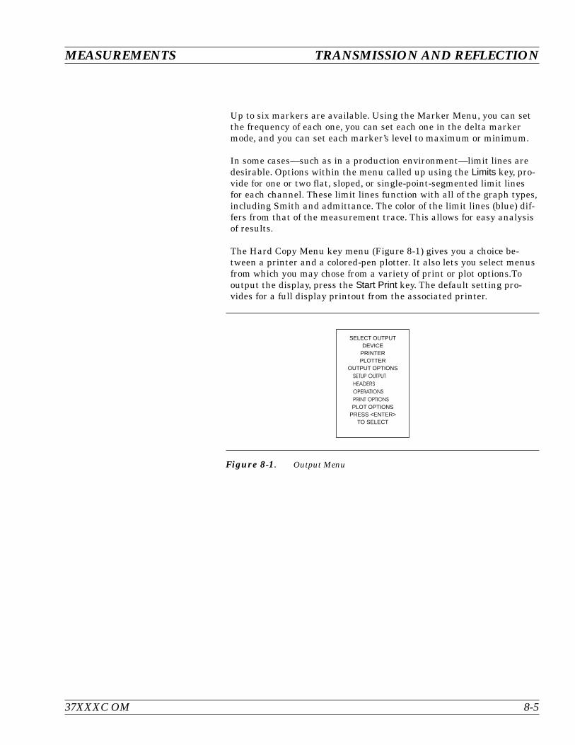
Up to six markers are available. Using the Marker Menu, you can setthe frequency of each one, you can set each one in the delta markermode, and you can set each marker’s level to maximum or minimum.
In some cases—such as in a production environment—limit lines aredesirable. Options within the menu called up using the Limits key, pro-vide for one or two flat, sloped, or single-point-segmented limit linesfor each channel. These limit lines function with all of the graph types,including Smith and admittance. The color of the limit lines (blue) dif-fers from that of the measurement trace. This allows for easy analysisof results.
The Hard Copy Menu key menu (Figure 8-1) gives you a choice be-tween a printer and a colored-pen plotter. It also lets you select menusfrom which you may chose from a variety of print or plot options.Tooutput the display, press the Start Print key. The default setting pro-vides for a full display printout from the associated printer.
37XXXC OM 8-5
MEASUREMENTS TRANSMISSION AND REFLECTION
Figure 8-1. Output Menu
SELECT OUTPUTDEVICE
PRINTERPLOTTER
OUTPUT OPTIONSSETUP OUTPUTHEADERSOPERATIONSPRINT OPTIONSPLOT OPTIONS
PRESS <ENTER>TO SELECT
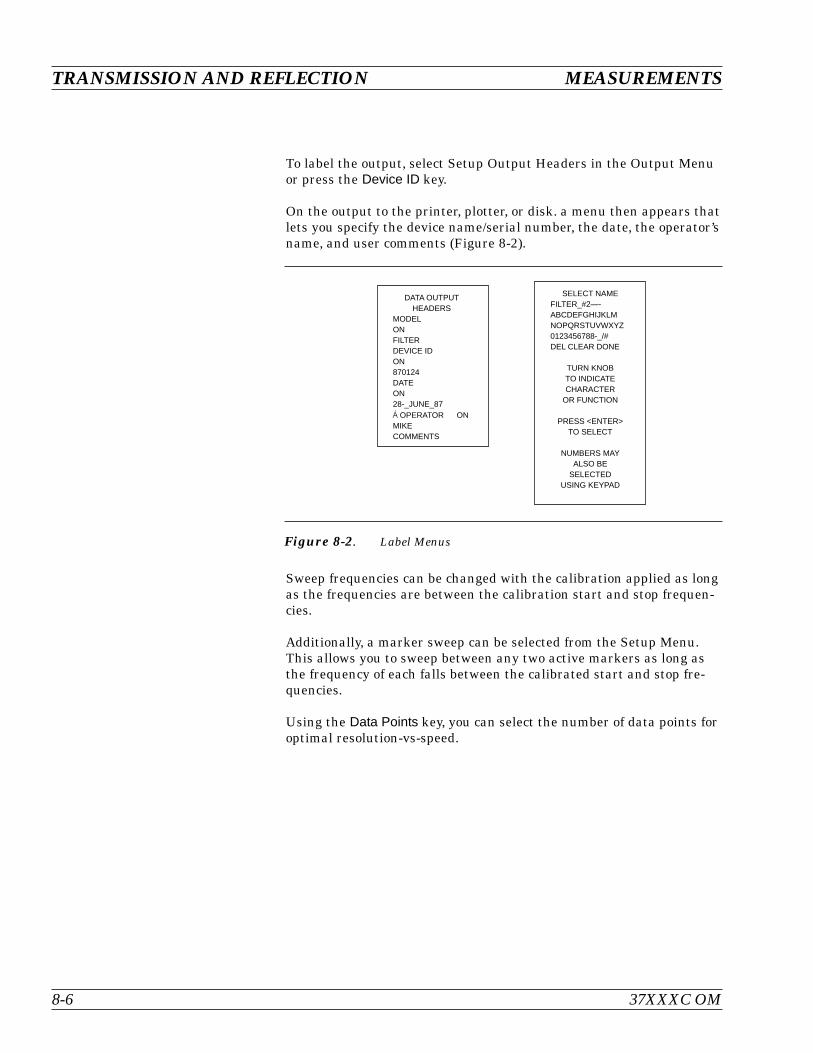
To label the output, select Setup Output Headers in the Output Menuor press the Device ID key.
On the output to the printer, plotter, or disk. a menu then appears thatlets you specify the device name/serial number, the date, the operator’sname, and user comments (Figure 8-2).
Sweep frequencies can be changed with the calibration applied as longas the frequencies are between the calibration start and stop frequen-cies.
Additionally, a marker sweep can be selected from the Setup Menu.This allows you to sweep between any two active markers as long asthe frequency of each falls between the calibrated start and stop fre-quencies.
Using the Data Points key, you can select the number of data points foroptimal resolution-vs-speed.
TRANSMISSION AND REFLECTION MEASUREMENTS
8-6 37XXXC OM
Figure 8-2. Label Menus
DATA OUTPUTHEADERS
MODELONFILTERDEVICE IDON870124DATEON28-_JUNE_87Á OPERATOR ONMIKECOMMENTS
SELECT NAMEFILTER_#2—-ABCDEFGHIJKLMNOPQRSTUVWXYZ0123456788-_/#DEL CLEAR DONE
TURN KNOBTO INDICATECHARACTER
OR FUNCTION
PRESS <ENTER>TO SELECT
NUMBERS MAYALSO BE
SELECTEDUSING KEYPAD
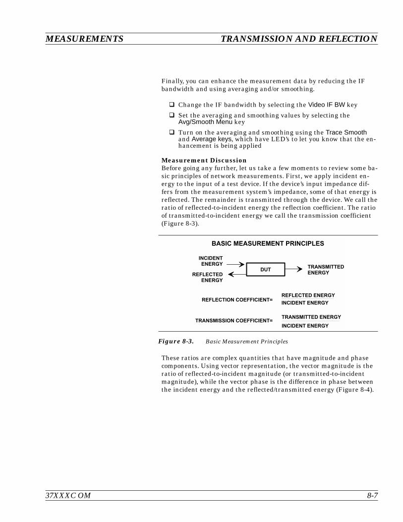
Finally, you can enhance the measurement data by reducing the IFbandwidth and using averaging and/or smoothing.
Change the IF bandwidth by selecting the Video IF BW key
Set the averaging and smoothing values by selecting theAvg/Smooth Menu key
Turn on the averaging and smoothing using the Trace Smoothand Average keys, which have LED’s to let you know that the en-hancement is being applied
Measurement DiscussionBefore going any further, let us take a few moments to review some ba-sic principles of network measurements. First, we apply incident en-ergy to the input of a test device. If the device’s input impedance dif-fers from the measurement system’s impedance, some of that energy isreflected. The remainder is transmitted through the device. We call theratio of reflected-to-incident energy the reflection coefficient. The ratioof transmitted-to-incident energy we call the transmission coefficient(Figure 8-3).
These ratios are complex quantities that have magnitude and phasecomponents. Using vector representation, the vector magnitude is theratio of reflected-to-incident magnitude (or transmitted-to-incidentmagnitude), while the vector phase is the difference in phase betweenthe incident energy and the reflected/transmitted energy (Figure 8-4).
37XXXC OM 8-7
MEASUREMENTS TRANSMISSION AND REFLECTION
%
% % % (
% % (
%
)
Figure 8-3. Basic Measurement Principles
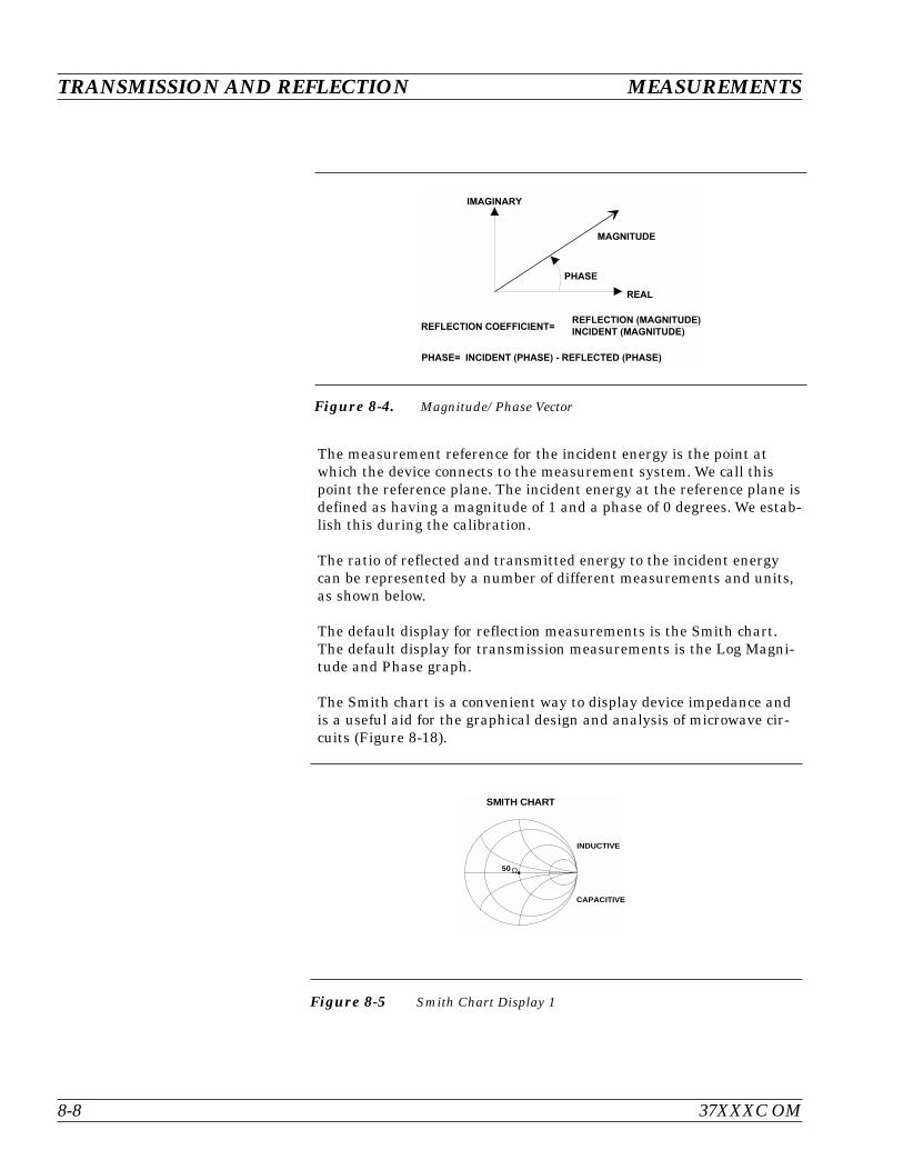
The measurement reference for the incident energy is the point atwhich the device connects to the measurement system. We call thispoint the reference plane. The incident energy at the reference plane isdefined as having a magnitude of 1 and a phase of 0 degrees. We estab-lish this during the calibration.
The ratio of reflected and transmitted energy to the incident energycan be represented by a number of different measurements and units,as shown below.
The default display for reflection measurements is the Smith chart.The default display for transmission measurements is the Log Magni-tude and Phase graph.
The Smith chart is a convenient way to display device impedance andis a useful aid for the graphical design and analysis of microwave cir-cuits (Figure 8-18).
TRANSMISSION AND REFLECTION MEASUREMENTS
8-8 37XXXC OM
% % % ( %
( %
Figure 8-4. Magnitude/Phase Vector
50
INDUCTIVE
CAPACITIVE
SMITH CHART
Ω
Figure 8-5 Smith Chart Display 1
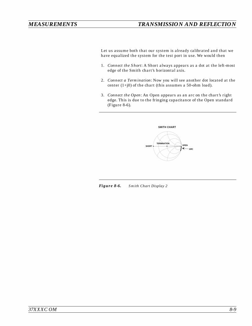
Let us assume both that our system is already calibrated and that wehave equalized the system for the test port in use. We would then
1. Connect the Short: A Short always appears as a dot at the left-mostedge of the Smith chart’s horizontal axis.
2. Connect a Termination: Now you will see another dot located at thecenter (1+j0) of the chart (this assumes a 50-ohm load).
3. Connect the Open: An Open appears as an arc on the chart’s rightedge. This is due to the fringing capacitance of the Open standard(Figure 8-6).
37XXXC OM 8-9
MEASUREMENTS TRANSMISSION AND REFLECTION
SMITH CHART
SHORT OPEN
ARC
TERMINATION
Figure 8-6. Smith Chart Display 2
Now let’s perform a reflection measurement on a 20 dB attenuatorover the 1 to 18 GHz range.
We need to determine the setup, calibration, and measurement re-quirements.
A known good starting point is to reset with Default Program parame-ters. Since our measurement lies between 1 and 18 GHz, set the Startand Stop frequencies using the Sweep Setup menu that appears on thedisplay following system reset.
Let’s perform a simple Reflection Only calibration, which uses an open,a short, and a broadband load. To do this, press the Begin Cal key andfollow the directions in the menu area.
When you complete the calibration, the “CHANNEL 1 WITH S11”Smith chart appears on the display. Now:
1. Select the Log Magnitude display and install the attenuator.
2. Select Auto Scale to optimize the display data.
3. Use Markers 1 and 2 to find the maximum and minimum imped-ance.
TRANSMISSION AND REFLECTION MEASUREMENTS
8-10 37XXXC OM

Now let us perform a transmission measurement on the same 20 dBattenuator over the same frequency range. We will follow the samesteps as before, but this time we will use additional features.
Once again, reset the system using the Default Program key.
In this calibration we will select the N-Discrete Frequencies menu op-tion and step all frequencies in increments of 50 MHz.
When the calibration is complete, Channel 1 will display “S21 FOR-WARD TRANSMISSION WITH LOG MAGNITUDE AND PHASE.”You can use Markers 1 and 2 to find the maximum and minimum val-ues of the attenuators insertion loss.
37XXXC OM 8-11
MEASUREMENTS TRANSMISSION AND REFLECTION
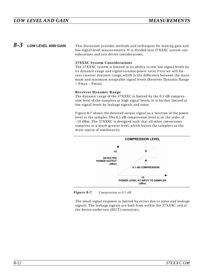
8-3 LOW LEVEL AND GAIN This discussion provides methods and techniques for making gain andlow-signal-level measurements. It is divided into 37XXXC system con-siderations and test device considerations.
37XXXC System ConsiderationsThe 37XXXC system is limited in its ability to test low-signal levels byits dynamic range and signal-to-noise-power ratio. First we will dis-cuss receiver dynamic range, which is the difference between the maxi-mum and minimum acceptable signal levels (Receiver Dynamic Range= Pmax – Pmin).
Receiver Dynamic RangeThe dynamic range of the 37XXXC is limited by the 0.1 dB compres-sion level of the samplers at high signal levels. It is further limited atlow signal levels by leakage signals and noise.
Figure 8-7 shows the detected output signal as a function of the powerlevel at the sampler. The 0.1 dB compression level is on the order of–10 dBm. The 37XXXC is designed such that all other conversionscompress at a much greater level, which leaves the samplers as themain source of nonlinearity.
The small signal response is limited by errors due to noise and leakagesignals. The leakage signals are both from within the 37XXXC and atthe device-under-test (DUT) connectors.
LOW LEVEL AND GAIN MEASUREMENTS
8-12 37XXXC OM
'
* ) +
* ) +
' , * )
'
Figure 8-7. Compression at 0.1 dB

The detected signal is the vector sum of the desired signals, the noisesignals, and the leakage signals. These signals introduce an error oruncertainty (Figure 8-8).
Some of the possible leakage paths for the 37XXXC are the transferswitch, the frequency conversion module, and the DUT. The systemlimits these leakages to greater than 100 dB. The 12-term error correc-tion can reduce this leakage to better than 110 dB at 18 GHz and90 dB at 40 GHz.
NOTEWe recommend using an isolation cell to decrease leakagesignals for sensitive measurements. For best results, in-crease the default averaging value and decrease the de-fault IF bandwidth setting during calibration andmeasurement. Using higher enhancement during the mea-surement than the calibration will not result in any accu-racy improvements.
The DUT connectors should have internally captivated center pins.Those connectors which use external pins to captivate the center con-ductor should have silver loaded epoxy on the pins to reduce radiationto better than 80 dB.
Signal-to-Noise-Power RatioThe signal-to-noise-power ratio for each of the test or reference chan-nels is as shown. The “signal power” is the power level of the 80 kHzIF signal at the internal synchronous detectors, and the “noise power”is the total power contained within the bandwidth of the bandpass fil-ter at 80 kHz.
The uncertainty, or error, in a measurement is a function of the ampli-tude of leakage signals and of the noise level. The uncertainty in themeasurement of magnitude and phase of the S-parameters are calcula-ble and shown in Figures 8-9 and 8-10.
37XXXC OM 8-13
MEASUREMENTS LOW LEVEL AND GAIN
- %
Figure 8-8. Amplitude and Phase Uncertainty

LOW LEVEL AND GAIN MEASUREMENTS
8-14 37XXXC OM
' ' , '
' , '
, '
,
, '
, ' '
, ' ' '
' ' " ' ' # ' & ' . '
* ) +
/ * )
% % % /
Figure 8-9. The Effect of S/N Ratio On Magnitude Measurements (NoiseOnly)
' ' , '
,
' ' " ' ' # ' & ' . '
/ * )
' , '
, '
% % % /
Figure 8-10. The Effect of S/N Ratio On Phase Measurements (Noise Only)

The most difficult types of measurements are those that exercise thefull dynamic range of the 37XXXC, such as filters (Figure 8-). Filtermeasurements are examples of where one must observe bothlow-insertion loss (in the passband) and high attenuation (in the stopband).
There are two techniques that you can use to optimize the sig-nal-to-noise ratio. They are (1) maximizing the RF signal level and (2)using signal enhancement.
To maximize the RF signal level, use the default settings of the37XXXC.
The 37XXXC provides two enhancements for improving the sig-nal-to-noise ratio: IF bandwidth reduction and averaging.
Reducing the IF bandwidth is a primary method for enhancing accu-racy. The 37XXXC has a choice of four bandwidths available from thefront panel: Maximum (10 kHz), Normal (1 kHz), Reduced (100 Hz),and Minimum (10 Hz). The noise level should decrease by a factorequal to the square root of the IF bandwidth. Using IF Bandwidth re-duction makes for faster measurements than with the use of an equiv-alent amount of averaging.
37XXXC OM 8-15
MEASUREMENTS LOW LEVEL AND GAIN
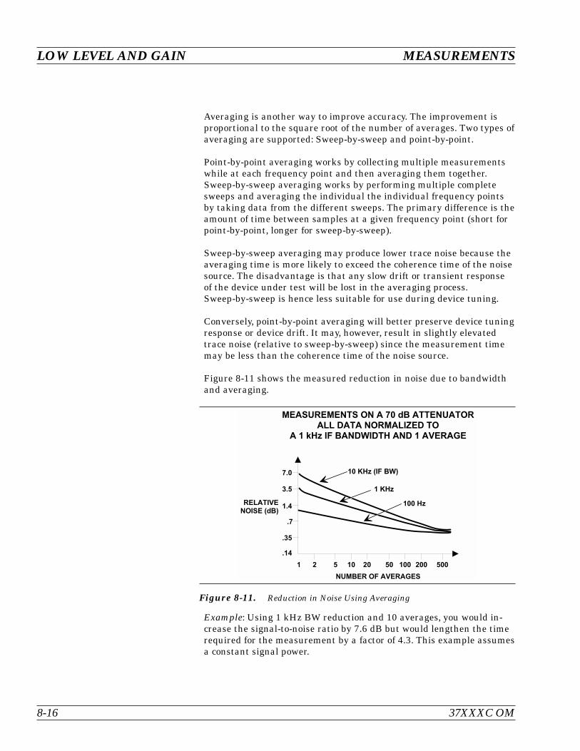
Averaging is another way to improve accuracy. The improvement isproportional to the square root of the number of averages. Two types ofaveraging are supported: Sweep-by-sweep and point-by-point.
Point-by-point averaging works by collecting multiple measurementswhile at each frequency point and then averaging them together.Sweep-by-sweep averaging works by performing multiple completesweeps and averaging the individual the individual frequency pointsby taking data from the different sweeps. The primary difference is theamount of time between samples at a given frequency point (short forpoint-by-point, longer for sweep-by-sweep).
Sweep-by-sweep averaging may produce lower trace noise because theaveraging time is more likely to exceed the coherence time of the noisesource. The disadvantage is that any slow drift or transient responseof the device under test will be lost in the averaging process.Sweep-by-sweep is hence less suitable for use during device tuning.
Conversely, point-by-point averaging will better preserve device tuningresponse or device drift. It may, however, result in slightly elevatedtrace noise (relative to sweep-by-sweep) since the measurement timemay be less than the coherence time of the noise source.
Figure 8-11 shows the measured reduction in noise due to bandwidthand averaging.
Example: Using 1 kHz BW reduction and 10 averages, you would in-crease the signal-to-noise ratio by 7.6 dB but would lengthen the timerequired for the measurement by a factor of 4.3. This example assumesa constant signal power.
LOW LEVEL AND GAIN MEASUREMENTS
8-16 37XXXC OM
0 ' * ) 1
2 3 % )
* )
) %
0 , '
, &
, #
, &
, #
" & ' " ' & ' ' ' " ' ' & ' '
' - 3 % )
- 3
' ' 3
, 0
Figure 8-11. Reduction in Noise Using Averaging

Test Device (DUT) ConsiderationsIn order to test a device, the required input RF level and the expecteddevice output RF level must be determined.
The RF level at Port 1 must be set for the device input RF power levelrequired. Attenuation can be added in steps of 10 dB up to 70 dB usingthe built-in source attenuator. Amplification can be added by removingthe front panel loop and adding an external amplifier.
Before calibration, ensure that the test setup is correct by setting thepower level and adding attenuation as needed.
37XXXC OM 8-17
MEASUREMENTS LOW LEVEL AND GAIN

The 37XXXC uses enhancements in the calibration to ensure a widedynamic range. It automatically selects 1 kHz IF bandwidth and var-ies the number of averages with the calibration device. Terminationsrequire the most averages.
If desired, the Video IF bandwidth and number of averages can bespecified for the calibration measurements. Using 100 averages (Avg =100) appears to be sufficient for most measurements.
To obtain the maximum performance from the 37XXXC for measure-ments of attenuation, you can use the capability of the N discrete fre-quency calibration to spot check measurements in the frequency bandof interest.
LOW LEVEL AND GAIN MEASUREMENTS
8-18 37XXXC OM

Wide Dynamic Range Device - FilterSince you do both low-insertion-loss and high- attenuation measure-ments simultaneously, use the maximum RF signal level and no atten-uation. Selecting the 1 kHz Video IF BW setting and 100 averages willlikely suffice for this kind of measurement.
High Gain Device - FETThis device has a typical 15 dB gain and requires an input level ofabout –30 dBm. Set the Port 1 Source Attenuator to 30 dB. Since thedevice RF output level is –15 dBm (–30 dBm + 15 dB[gain] = –15 dBm)no attenuation is needed at Port 2.
Medium Power Device - AmplifierMeasure the small signal parameters of a 10 dB gain device that re-quires an input power level of 0 dBm. Here, Port 1 will have no attenu-ation. The device RF output level is 10 dBm. This level equals 10 dBm(0 dBm + 10 dB[gain] = 10 dBm) into Port 2 and will cause compres-sion in the measurement. At least 10 dB of test attenuation will beneeded at Port 2, which will reduce the Port 2 RF level to 0 dB.
37XXXC OM 8-19
MEASUREMENTS LOW LEVEL AND GAIN
) 4 * )
% 5
* )
) %
' * )
) 6 & ' * )
"
Figure 8-12. Filter Measurements
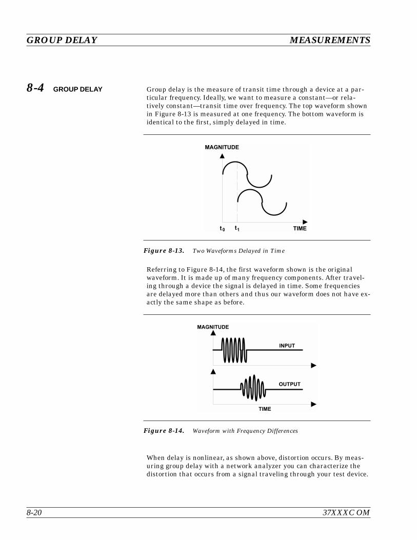
8-4 GROUP DELAY Group delay is the measure of transit time through a device at a par-ticular frequency. Ideally, we want to measure a constant—or rela-tively constant—transit time over frequency. The top waveform shownin Figure 8-13 is measured at one frequency. The bottom waveform isidentical to the first, simply delayed in time.
Referring to Figure 8-14, the first waveform shown is the originalwaveform. It is made up of many frequency components. After travel-ing through a device the signal is delayed in time. Some frequenciesare delayed more than others and thus our waveform does not have ex-actly the same shape as before.
When delay is nonlinear, as shown above, distortion occurs. By meas-uring group delay with a network analyzer you can characterize thedistortion that occurs from a signal traveling through your test device.
GROUP DELAY MEASUREMENTS
8-20 37XXXC OM
'
Figure 8-13. Two Waveforms Delayed in Time
Figure 8-14. Waveform with Frequency Differences
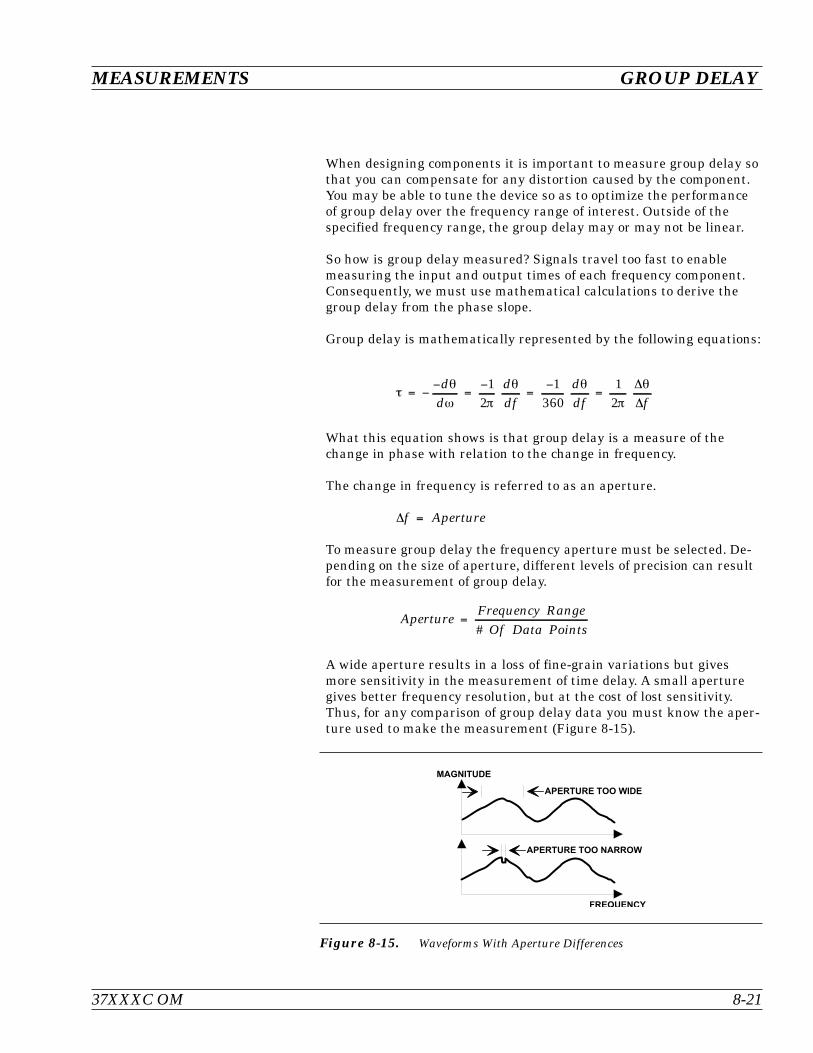
When designing components it is important to measure group delay sothat you can compensate for any distortion caused by the component.You may be able to tune the device so as to optimize the performanceof group delay over the frequency range of interest. Outside of thespecified frequency range, the group delay may or may not be linear.
So how is group delay measured? Signals travel too fast to enablemeasuring the input and output times of each frequency component.Consequently, we must use mathematical calculations to derive thegroup delay from the phase slope.
Group delay is mathematically represented by the following equations:
dd
ddf
ddf f
12
1360
12
What this equation shows is that group delay is a measure of thechange in phase with relation to the change in frequency.
The change in frequency is referred to as an aperture.
f Aperture
To measure group delay the frequency aperture must be selected. De-pending on the size of aperture, different levels of precision can resultfor the measurement of group delay.
ApertureFrequency Range
Of Data Points
#
A wide aperture results in a loss of fine-grain variations but givesmore sensitivity in the measurement of time delay. A small aperturegives better frequency resolution, but at the cost of lost sensitivity.Thus, for any comparison of group delay data you must know the aper-ture used to make the measurement (Figure 8-15).
37XXXC OM 8-21
MEASUREMENTS GROUP DELAY
% 5
Figure 8-15. Waveforms With Aperture Differences
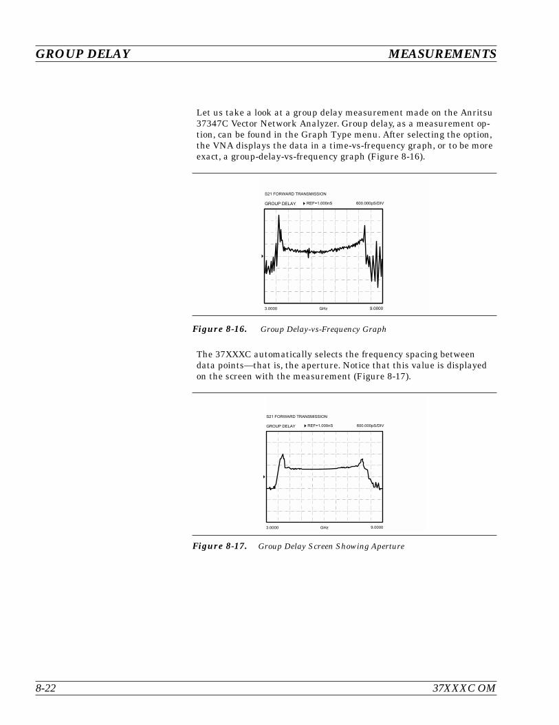
Let us take a look at a group delay measurement made on the Anritsu37347C Vector Network Analyzer. Group delay, as a measurement op-tion, can be found in the Graph Type menu. After selecting the option,the VNA displays the data in a time-vs-frequency graph, or to be moreexact, a group-delay-vs-frequency graph (Figure 8-16).
The 37XXXC automatically selects the frequency spacing betweendata points—that is, the aperture. Notice that this value is displayedon the screen with the measurement (Figure 8-17).
GROUP DELAY MEASUREMENTS
8-22 37XXXC OM
% #
' ! # ( O . 7 7 7 6 7 7 . 7 7 7 $ # &
G . 7 7 7 7: . 7 7 7 7 ' " ;
Figure 8-16. Group Delay-vs-Frequency Graph
% #
' ! # ( O . 7 7 7 6 7 7 . 7 7 7 $ # &
G . 7 7 7 7: . 7 7 7 7 ' " ;
Figure 8-17. Group Delay Screen Showing Aperture
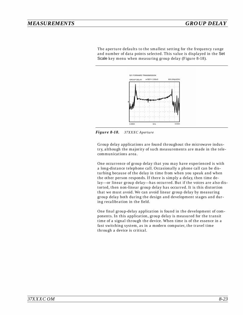
The aperture defaults to the smallest setting for the frequency rangeand number of data points selected. This value is displayed in the SetScale key menu when measuring group delay (Figure 8-18).
Group delay applications are found throughout the microwave indus-try, although the majority of such measurements are made in the tele-communications area.
One occurrence of group delay that you may have experienced is witha long-distance telephone call. Occasionally a phone call can be dis-turbing because of the delay in time from when you speak and whenthe other person responds. If there is simply a delay, then time de-lay—or linear group delay—has occurred. But if the voices are also dis-torted, then non-linear group delay has occurred. It is this distortionthat we must avoid. We can avoid linear group delay by measuringgroup delay both during the design and development stages and dur-ing recalibration in the field.
One final group-delay application is found in the development of com-ponents. In this application, group delay is measured for the transittime of a signal through the device. When time is of the essence in afast switching system, as in a modern computer, the travel timethrough a device is critical.
37XXXC OM 8-23
MEASUREMENTS GROUP DELAY
% #
' ! # ( O . 7 7 7 6 7 7 . 7 7 7 $ # &
G . 7 7 7 7: . 7 7 7 7 ' " ;
Figure 8-18. 37XXXC Aperture

8-5 ACTIVE DEVICE Active devices are key components in microwave systems.
The measurements that are made on active devices are similar tothose made on passive devices.
Active devices come in many shapes and sizes. In most cases we aregoing to have to develop a fixture in which to mount the device.
Active devices require bias voltages, and in many cases they are easilydamaged. High gain amplifiers may saturate with input signals of–50 dBm. With active devices, we have a new set of measurement re-quirements.
The 373XXC has been designed to help you make these types of mea-surements. It includes one 70 dB step attenuator (60 dB for 37377Cand 37397C) used to adjust the Port 1 power level. A second 40 dB stepattenuator is also included (with Option 6) in the forward transmis-sion path to allow measurement of high gain devices without sacrific-ing reverse transmission and reflection measurements (S12, S22). Biastees on each port are used to bias the device via the test port centerconductor. This approach to bias is useful for testing transistors; how-ever, MMIC’s usually require bias injection at other points (Fig-ure 8-19).
ACTIVE DEVICE MEASUREMENTS
8-24 37XXXC OM
) 7 8 9 9
%
)
Figure 8-19. Bias Tee
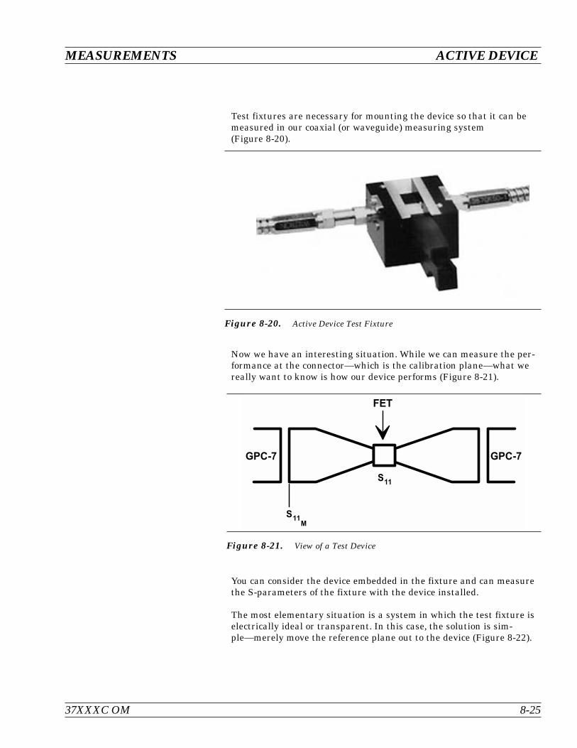
Test fixtures are necessary for mounting the device so that it can bemeasured in our coaxial (or waveguide) measuring system(Figure 8-20).
Now we have an interesting situation. While we can measure the per-formance at the connector—which is the calibration plane—what wereally want to know is how our device performs (Figure 8-21).
You can consider the device embedded in the fixture and can measurethe S-parameters of the fixture with the device installed.
The most elementary situation is a system in which the test fixture iselectrically ideal or transparent. In this case, the solution is sim-ple—merely move the reference plane out to the device (Figure 8-22).
37XXXC OM 8-25
MEASUREMENTS ACTIVE DEVICE
Figure 8-20. Active Device Test Fixture
%
0
0
Figure 8-21. View of a Test Device
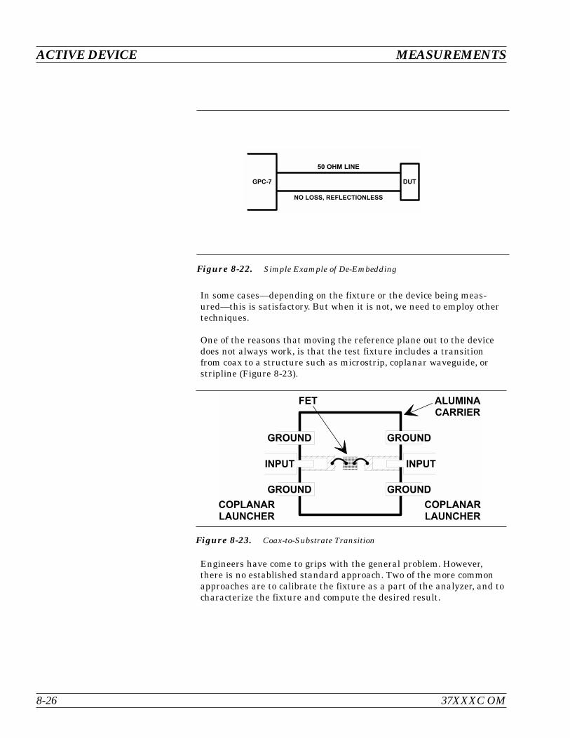
In some cases—depending on the fixture or the device being meas-ured—this is satisfactory. But when it is not, we need to employ othertechniques.
One of the reasons that moving the reference plane out to the devicedoes not always work, is that the test fixture includes a transitionfrom coax to a structure such as microstrip, coplanar waveguide, orstripline (Figure 8-23).
Engineers have come to grips with the general problem. However,there is no established standard approach. Two of the more commonapproaches are to calibrate the fixture as a part of the analyzer, and tocharacterize the fixture and compute the desired result.
ACTIVE DEVICE MEASUREMENTS
8-26 37XXXC OM
0
& '
$ %
Figure 8-22. Simple Example of De-Embedding
%
Figure 8-23. Coax-to-Substrate Transition
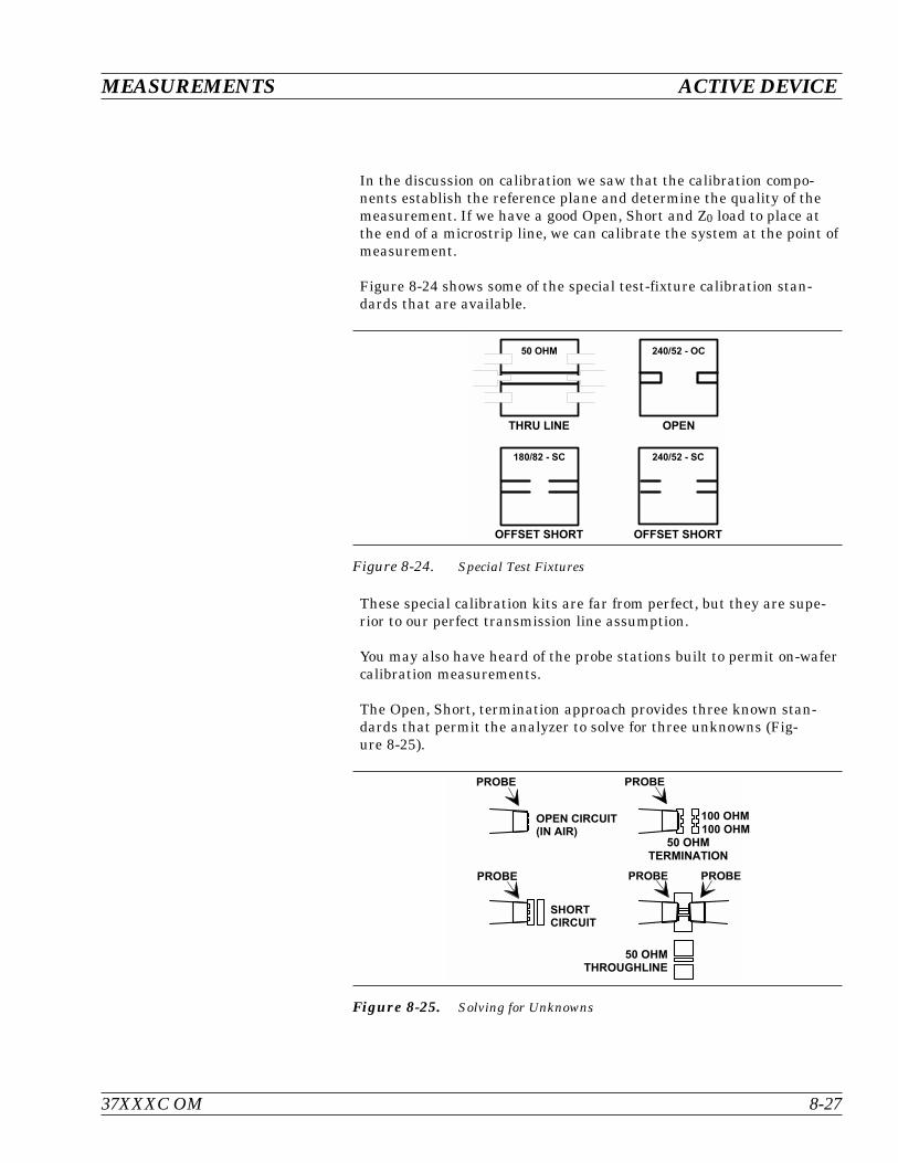
In the discussion on calibration we saw that the calibration compo-nents establish the reference plane and determine the quality of themeasurement. If we have a good Open, Short and Z0 load to place atthe end of a microstrip line, we can calibrate the system at the point ofmeasurement.
Figure 8-24 shows some of the special test-fixture calibration stan-dards that are available.
These special calibration kits are far from perfect, but they are supe-rior to our perfect transmission line assumption.
You may also have heard of the probe stations built to permit on-wafercalibration measurements.
The Open, Short, termination approach provides three known stan-dards that permit the analyzer to solve for three unknowns (Fig-ure 8-25).
37XXXC OM 8-27
MEASUREMENTS ACTIVE DEVICE
% %
% %
& '
: ' / : " " # ' / & "
" # ' / & "
Figure 8-24. Special Test Fixtures
& '
)
& '
) )
' '
' '
) )
Figure 8-25. Solving for Unknowns
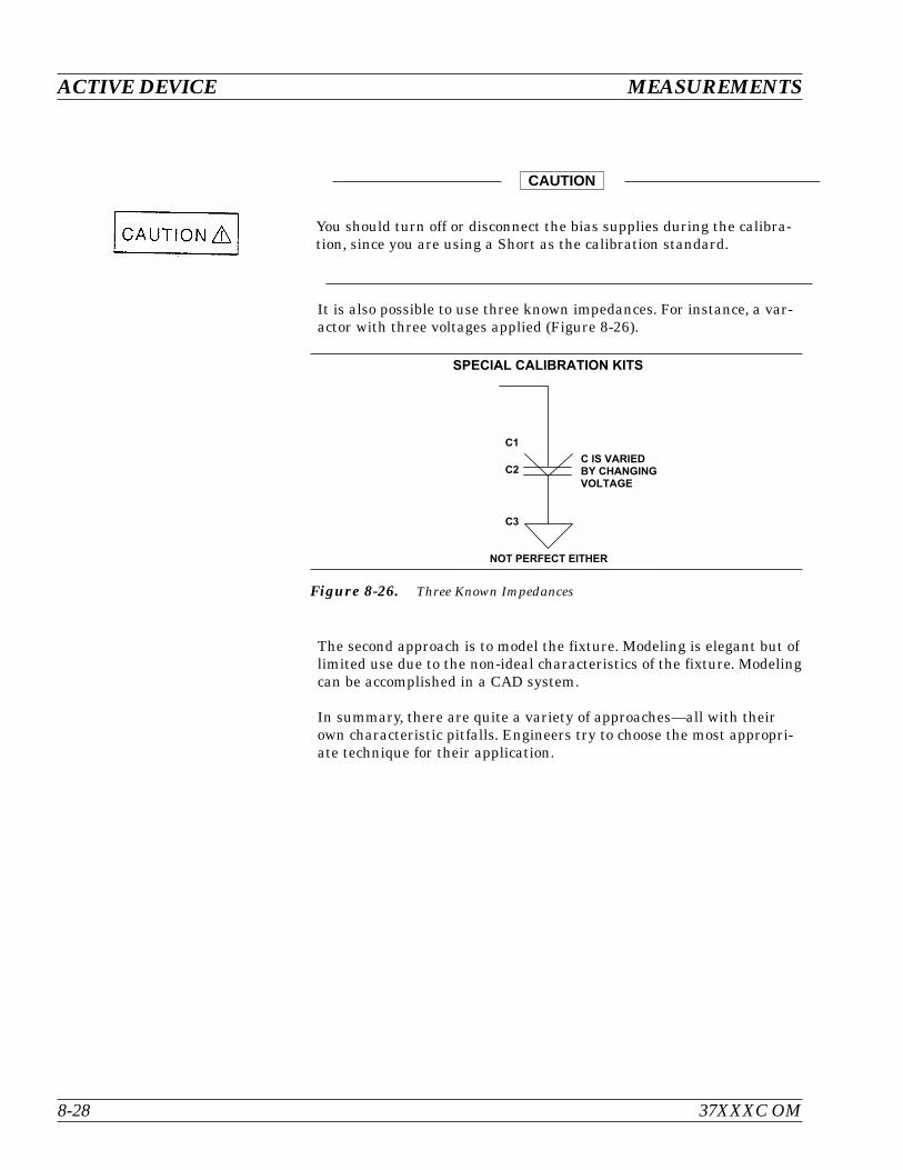
It is also possible to use three known impedances. For instance, a var-actor with three voltages applied (Figure 8-26).
The second approach is to model the fixture. Modeling is elegant but oflimited use due to the non-ideal characteristics of the fixture. Modelingcan be accomplished in a CAD system.
In summary, there are quite a variety of approaches—all with theirown characteristic pitfalls. Engineers try to choose the most appropri-ate technique for their application.
ACTIVE DEVICE MEASUREMENTS
8-28 37XXXC OM
"
)
%
) -
Figure 8-26. Three Known Impedances
You should turn off or disconnect the bias supplies during the calibra-tion, since you are using a Short as the calibration standard.
CAUTION
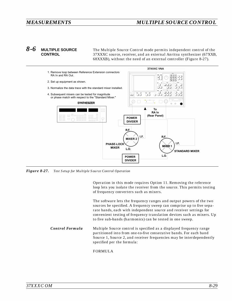
8-6 MULTIPLE SOURCECONTROL
The Multiple Source Control mode permits independent control of the37XXXC source, receiver, and an external Anritsu synthesizer (67XXB,68XXXB), without the need of an external controller (Figure 8-27).
Operation in this mode requires Option 11. Removing the referenceloop lets you isolate the receiver from the source. This permits testingof frequency converters such as mixers.
The software lets the frequency ranges and output powers of the twosources be specified. A frequency sweep can comprise up to five sepa-rate bands, each with independent source and receiver settings forconvenient testing of frequency translation devices such as mixers. Upto five sub-bands (harmonics) can be tested in one sweep.
Control Formula Multiple Source control is specified as a displayed frequency rangepartitioned into from one-to-five consecutive bands. For each bandSource 1, Source 2, and receiver frequencies may be interdependentlyspecified per the formula:
FORMULA
37XXXC OM 8-29
MEASUREMENTS MULTIPLE SOURCE CONTROL
I.F.
L.O.
R.F.
MIXER 1
372XXA VECTOR NETWORK ANALYZER
I.F.
L.O.
R.F.
MIXER 2
ToRA In
(Rear Panel)
STANDARD MIXER
PHASE-LOCK
MIXER
1. Remove loop between Reference Extension connectorsRA In and RA Out.
2. Set up equipment as shown.
3. Normalize the data trace with the standard mixer installed.
4. Subsequent mixers can be tested for magnitudeor phase match with respect to the "Standard Mixer."
POWER
DIVIDER
POWER
DIVIDER
67XXBSYNTHESIZER
Figure 8-27. Test Setup for Multiple Source Control Operation
37XXXC VNA

Multiple Source Control Pre-operational SetupThe two sources receive control information from the 37XXXC VNA.The GPIB address assigned to the external source must be identical tothe address contained in the data directed to the source by the37XXXC VNA. Assure source/VNA address compatibility as follows:
Step 1. Install Sources 1 and 2 on the Dedicated GPIB bus.
Step 2. Press the Utility Menu key.
Step 3. Move cursor to GPIB ADDRESSES and press Enter,when menu U1 (left) appears.
Step 4. When menu GP7 (left) appears, observe that the ad-dress number is correct. If necessary, use the keypadto enter a new address.
MULTIPLE SOURCE CONTROL MEASUREMENTS
8-30 37XXXC OM
MENU U1
SELECT UTILITYFUNCTION OPTIONS
GPIB ADDRESSES
DISPLAYINSTRUMENTSTATE PARAMS
GENERAL DISKUTILITIES
CAL COMPONENTUTILITIES
AUTOCAL UTILITIES
COLORCONFIGURATION
DATA ON(OFF)DRAWING
BLANKINGFREQUENCYINFORMATION
SET DATA/TIME
PRESS <ENTER>TO SELECT
OR TURN ON/OFF
MENU 7
GPIB ADDRESSES
IEEE 488.2GPIB INTERFACE
ADDRESS6
DEDICATEDGPIB INTERFACE
EXTERNAL SOURCE 14
EXTERNAL SOURCE 25
PLOTTER8
POWER METER23
FREQUENCY COUNTER7
DefaultProgram
UtilityMenu
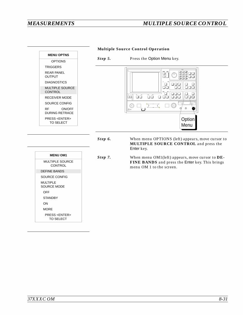
Multiple Source Control Operation
Step 5. Press the Option Menu key.
Step 6. When menu OPTIONS (left) appears, move cursor toMULTIPLE SOURCE CONTROL and press theEnter key.
Step 7. When menu OM1(left) appears, move cursor to DE-FINE BANDS and press the Enter key. This bringsmenu OM 1 to the screen.
37XXXC OM 8-31
MEASUREMENTS MULTIPLE SOURCE CONTROL
MENU OPTNS
OPTIONS
TRIGGERS
REAR PANELOUTPUT
DIAGNOSTICS
MULTIPLE SOURCECONTROL
RECEIVER MODE
SOURCE CONFIG
RF ON/OFFDURING RETRACE
PRESS <ENTER>TO SELECT
MENU OM1
MULTIPLE SOURCECONTROL
DEFINE BANDS
SOURCE CONFIG
MULTIPLESOURCE MODE
OFF
STANDBY
ON
MORE
PRESS <ENTER>TO SELECT
OptionMenu
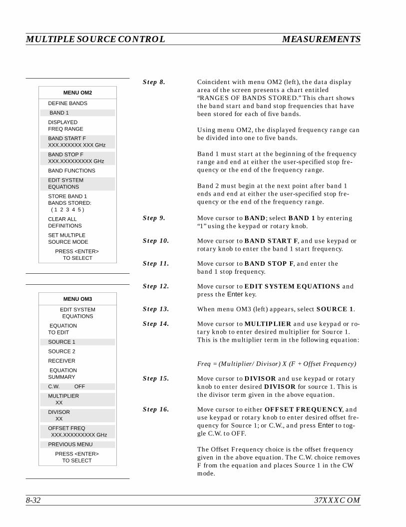
Step 8. Coincident with menu OM2 (left), the data displayarea of the screen presents a chart entitled“RANGES OF BANDS STORED.” This chart showsthe band start and band stop frequencies that havebeen stored for each of five bands.
Using menu OM2, the displayed frequency range canbe divided into one to five bands.
Band 1 must start at the beginning of the frequencyrange and end at either the user-specified stop fre-quency or the end of the frequency range.
Band 2 must begin at the next point after band 1ends and end at either the user-specified stop fre-quency or the end of the frequency range.
Step 9. Move cursor to BAND; select BAND 1 by entering“1” using the keypad or rotary knob.
Step 10. Move cursor to BAND START F, and use keypad orrotary knob to enter the band 1 start frequency.
Step 11. Move cursor to BAND STOP F, and enter theband 1 stop frequency.
Step 12. Move cursor to EDIT SYSTEM EQUATIONS andpress the Enter key.
Step 13. When menu OM3 (left) appears, select SOURCE 1.
Step 14. Move cursor to MULTIPLIER and use keypad or ro-tary knob to enter desired multiplier for Source 1.This is the multiplier term in the following equation:
Freq = (Multiplier/Divisor) X (F + Offset Frequency)
Step 15. Move cursor to DIVISOR and use keypad or rotaryknob to enter desired DIVISOR for source 1. This isthe divisor term given in the above equation.
Step 16. Move cursor to either OFFSET FREQUENCY, anduse keypad or rotary knob to enter desired offset fre-quency for Source 1; or C.W., and press Enter to tog-gle C.W. to OFF.
The Offset Frequency choice is the offset frequencygiven in the above equation. The C.W. choice removesF from the equation and places Source 1 in the CWmode.
MULTIPLE SOURCE CONTROL MEASUREMENTS
8-32 37XXXC OM
MENU OM2
DEFINE BANDS
BAND 1
DISPLAYEDFREQ RANGE
BAND START FXXX.XXXXXX XXX GHz
BAND STOP FXXX.XXXXXXXXX GHz
BAND FUNCTIONS
EDIT SYSTEMEQUATIONS
STORE BAND 1BANDS STORED:( 1 2 3 4 5 )
CLEAR ALLDEFINITIONS
SET MULTIPLESOURCE MODE
PRESS <ENTER>TO SELECT
MENU OM3
EDIT SYSTEMEQUATIONS
EQUATIONTO EDIT
SOURCE 1
SOURCE 2
RECEIVER
EQUATIONSUMMARY
C.W. OFF
MULTIPLIERXX
DIVISORXX
OFFSET FREQXXX.XXXXXXXXX GHz
PREVIOUS MENU
PRESS <ENTER>TO SELECT
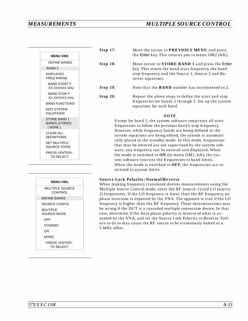
Step 17. Move the cursor to PREVIOUS MENU and pressthe Enter key. This returns you to menu OM2 (left).
Step 18. Move cursor to STORE BAND 1 and press the Enterkey. This stores the band start frequency, the bandstop frequency and the Source 1, Source 2 and Re-ceiver equations.
Step 19. Note that the BAND number has incremented to 2.
Step 20. Repeat the above steps to define the start and stopfrequencies for bands 2 through 5. Set up the systemequations for each band.
NOTEExcept for band 1, the system software constrains all startfrequencies to follow the previous band’s stop frequency.However, while frequency bands are being defined or thesystem equations are being edited, the system is automati-cally placed in the standby mode. In this mode, frequenciesthat may be entered are not supervised by the system soft-ware; any frequency can be entered and displayed. Whenthe mode is switched to ON (in menu OM1, left), the sys-tem software restricts the frequencies to band limits.When the mode is switched to OFF, the frequencies are re-stricted to system limits.
Source Lock Polarity: Normal/ReverseWhen making frequency translated devices measurements using theMultiple Source Control mode, enter the RF (source 1) and LO (source2) frequencies. If the LO frequency is lower than the RF frequency, nophase inversion is expected by the VNA. The opposite is true if the LOfrequency is higher than the RF frequency. These determinations maybe wrong if the DUT is a cascaded multiple conversion device. In thatcase, determine if the final phase polarity is inverse of what is as-sumed by the VNA, and set the Source Lock Polarity to Reverse. Fail-ure to do so may cause the RF source to be erroneously locked at a5 MHz offset.
37XXXC OM 8-33
MEASUREMENTS MULTIPLE SOURCE CONTROL
MENU OM2
DEFINE BANDS
BAND 2
DISPLAYEDFREQ RANGE
BAND START FXX.XXXXXX GHz
BAND STOP FXX.XXXXXX GHz
BAND FUNCTIONS
EDIT SYSTEMEQUATIONS
STORE BAND 1BANDS STORED:( NONE )
CLEAR ALLDEFINITIONS
SET MULTIPLESOURCE STATE
PRESS <ENTER>TO SELECT
MENU OM1
MULTIPLE SOURCECONTROL
DEFINE BANDS
SOURCE CONFIG
MULTIPLESOURCE MODE
OFF
STANDBY
ON
MORE
PRESS <ENTER>TO SELECT

8-7 ADAPTER REMOVAL Using adapters in VNA measurement applications can introduce com-plex errors that add to measurement uncertainty. The VNA AdapterRemoval procedure provides for adapter compensation. This on-screen,menu-driven procedure allows the use of a through-line device oradapter with different connector types (non-insertables) on either endto be used for measurement calibration. The electrical effects are sub-sequently compensated for. The Adapter Removal procedure is de-scribed below.
NOTEFor purposes of explanation, assume that the adapter to beused is a length of rigid coax with a type N male connectoron one end and an SMA male connector on the other end.Further assume that the Test Port 1 connector is a type Nfemale and that the Test Port 2 connector is an SMA fe-male (below).
Procedure:
Step 1. Press the Appl key (below) to display the APPLICA-TIONS menu (top left).
Step 2. Move the cursor to ADAPTER REMOVAL andpress the Enter key.
Step 3. Select HELP in the next menu (bottom left) to pro-duce the step-by-step procedure shown inFigure 8-28 (next page).
ADAPTER REMOVAL MEASUREMENTS
8-34 37XXXC OM
Test Adapter
Type N Male(X’)
SMA Male(Y’)
Electrical Length: 170 ps
MENU APPL
APPLICATIONS
ADAPTER REMOVAL
SWEPT FREQUENCYGAIN COMPRESSION
SWEPT POWERGAIN COMPRESSION
E/O MEASUREMENT
O/E MEASUREMENT
MERGE CAL FILES
PRESS <ENTER>TO SELECT
MENU CAR1
ADAPTER REMOVAL
12-TERM CALS FORX AND YMUST EXIST IN THECURRENT DIREC-TORY
ELECTRICAL LENGTHOF THE ADAPTER+XXX.XXXXX ps
REMOVE ADAPTER
HELP
PRESS <ENTER>TO SELECT
Appl
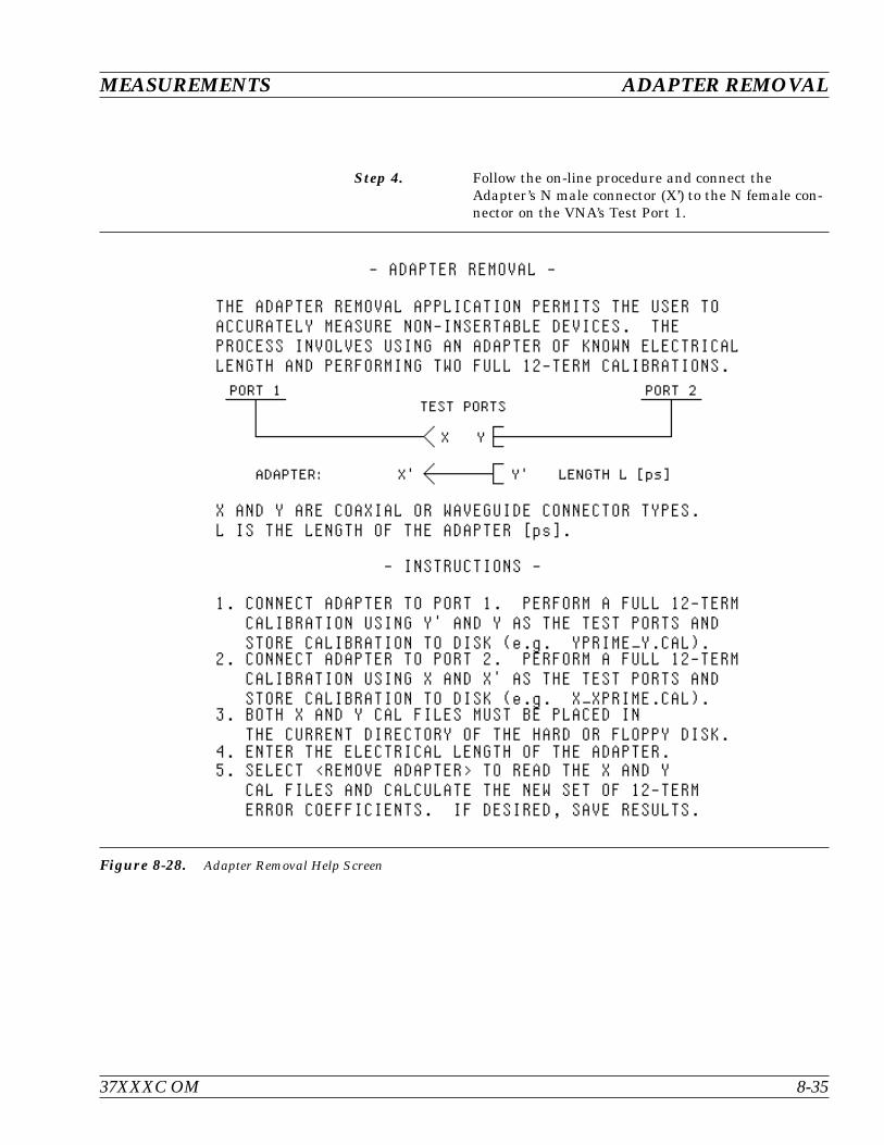
Step 4. Follow the on-line procedure and connect theAdapter’s N male connector (X’) to the N female con-nector on the VNA’s Test Port 1.
37XXXC OM 8-35
MEASUREMENTS ADAPTER REMOVAL
Figure 8-28. Adapter Removal Help Screen
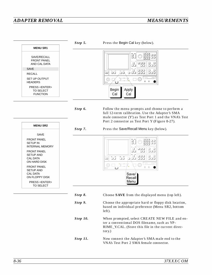
Step 5. Press the Begin Cal key (below).
Step 6. Follow the menu prompts and choose to perform afull 12-term calibration. Use the Adapter’s SMAmale connector (Y') as Test Port 1 and the VNA’s TestPort 2 connector as Test Port Y (Figure 8-27).
Step 7. Press the Save/Recall Menu key (below).
Step 8. Choose SAVE from the displayed menu (top left).
Step 9. Choose the appropriate hard or floppy disk location,based on individual preference (Menu SR2, bottomleft).
Step 10. When prompted, select CREATE NEW FILE and en-ter a conventional DOS filename, such as YP-RIME_Y.CAL. (Store this file in the current direc-tory.)
Step 11. Now connect the Adapter’s SMA male end to theVNA’s Test Port 2 SMA female connector.
ADAPTER REMOVAL MEASUREMENTS
8-36 37XXXC OM
- B G
> 4 6
:
7 . 8
#
K $
MENU SR1
SAVE/RECALLFRONT PANELAND CAL DATA
SAVE
RECALL
SET UP OUTPUTHEADERS
PRESS <ENTER>TO SELECTFUNCTION
MENU SR2
SAVE
FRONT PANELSETUP ININTERNAL MEMORY
FRONT PANELSETUP ANDCAL DATAON HARD DISK
FRONT PANELSETUP ANDCAL DATAON FLOPPY DISK
PRESS <ENTER>TO SELECT
ApplyCal
BeginCal
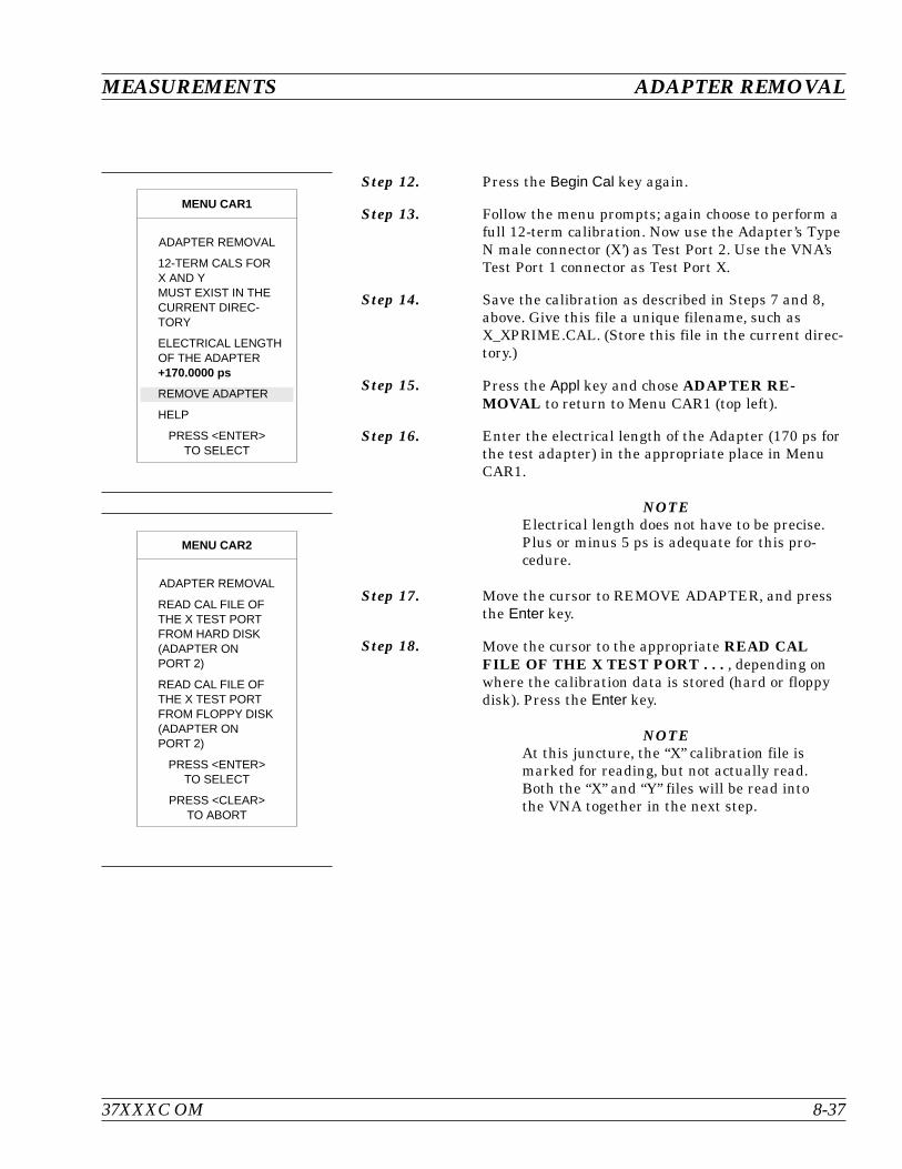
Step 12. Press the Begin Cal key again.
Step 13. Follow the menu prompts; again choose to perform afull 12-term calibration. Now use the Adapter’s TypeN male connector (X’) as Test Port 2. Use the VNA’sTest Port 1 connector as Test Port X.
Step 14. Save the calibration as described in Steps 7 and 8,above. Give this file a unique filename, such asX_XPRIME.CAL. (Store this file in the current direc-tory.)
Step 15. Press the Appl key and chose ADAPTER RE-MOVAL to return to Menu CAR1 (top left).
Step 16. Enter the electrical length of the Adapter (170 ps forthe test adapter) in the appropriate place in MenuCAR1.
NOTEElectrical length does not have to be precise.Plus or minus 5 ps is adequate for this pro-cedure.
Step 17. Move the cursor to REMOVE ADAPTER, and pressthe Enter key.
Step 18. Move the cursor to the appropriate READ CALFILE OF THE X TEST PORT . . . , depending onwhere the calibration data is stored (hard or floppydisk). Press the Enter key.
NOTEAt this juncture, the “X” calibration file ismarked for reading, but not actually read.Both the “X” and “Y” files will be read intothe VNA together in the next step.
37XXXC OM 8-37
MEASUREMENTS ADAPTER REMOVAL
MENU CAR1
ADAPTER REMOVAL
12-TERM CALS FORX AND YMUST EXIST IN THECURRENT DIREC-TORY
ELECTRICAL LENGTHOF THE ADAPTER+170.0000 ps
REMOVE ADAPTER
HELP
PRESS <ENTER>TO SELECT
MENU CAR2
ADAPTER REMOVAL
READ CAL FILE OFTHE X TEST PORTFROM HARD DISK(ADAPTER ONPORT 2)
READ CAL FILE OFTHE X TEST PORTFROM FLOPPY DISK(ADAPTER ONPORT 2)
PRESS <ENTER>TO SELECT
PRESS <CLEAR>TO ABORT
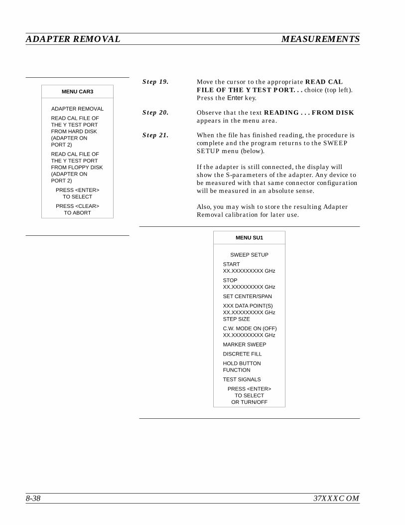
Step 19. Move the cursor to the appropriate READ CALFILE OF THE Y TEST PORT. . . choice (top left).Press the Enter key.
Step 20. Observe that the text READING . . . FROM DISKappears in the menu area.
Step 21. When the file has finished reading, the procedure iscomplete and the program returns to the SWEEPSETUP menu (below).
If the adapter is still connected, the display willshow the S-parameters of the adapter. Any device tobe measured with that same connector configurationwill be measured in an absolute sense.
Also, you may wish to store the resulting AdapterRemoval calibration for later use.
ADAPTER REMOVAL MEASUREMENTS
8-38 37XXXC OM
MENU CAR3
ADAPTER REMOVAL
READ CAL FILE OFTHE Y TEST PORTFROM HARD DISK(ADAPTER ONPORT 2)
READ CAL FILE OFTHE Y TEST PORTFROM FLOPPY DISK(ADAPTER ONPORT 2)
PRESS <ENTER>TO SELECT
PRESS <CLEAR>TO ABORT
MENU SU1
SWEEP SETUP
STARTXX.XXXXXXXXX GHz
STOPXX.XXXXXXXXX GHz
SET CENTER/SPAN
XXX DATA POINT(S)XX.XXXXXXXXX GHzSTEP SIZE
C.W. MODE ON (OFF)XX.XXXXXXXXX GHz
MARKER SWEEP
DISCRETE FILL
HOLD BUTTONFUNCTION
TEST SIGNALS
PRESS <ENTER>TO SELECT
OR TURN/OFF
8-8 GAIN COMPRESSION There are a number of ways to measure Gain Compression. With aVNA two approaches are possible: Swept Frequency Gain Compression(SFGC) and Swept Power Gain Compression (SPGC). The 37XXXC of-fers a very straightforward approach to each of these measurements.
It is normally desirable to make S-parameter measurements in thelinear operating region of an amplifier and then observe Compressionor amplitude-modulation/phase-modulation (AM/PM) characteristicsby increasing the input power to drive the amplifier into it's nonlinearregion. The characteristics of the amplifier-under-test (AUT) dictatethe operating power levels required for the tests. Prior to makingmeasurements on a specific amplifier the user must determine the de-sired operating levels. A recommended level for linear region operationis:
P = PG – Gain – 15dB (PGC=Nominal l dB compression of the AUT)
The actual level is constrained by the power available from the VNAand the built in 70 dB step attenuator. (In the case of the 37XXXC,available power is easily supplemented by the addition of an externalamplifier/attenuator combination.) Power input to Port 2 must also beconsidered as the test should not drive the VNA into nonlinear opera-tion. Typical specifications show 0.1dB compression at a VNA receiverinput level of –10 dBm. The receiver signal is derived through a 13 dBcoupler from the Port 2 signal. The 37XXXC also includes a 40 dB stepattenuator in this path that enables linear operation with input sig-nals as high as 30 dBm (1 watt), the maximum signal level that shouldbe input to Port 2. Higher power levels can be measured by attenuat-ing the signal prior to Port 2.
A typical power configuration example that will also be used through-out this section is included in Figure 8-28. A 10 dB pad has been usedat both Port 1 and Port 2 to minimize mismatch errors.
Power and VNAs It is necessary to measure absolute power to deter-mine Gain Compression. VNA receiver channels aretypically down-converters and do not measurepower directly. They are, however, linear so that anaccurate power calibration at one level will result ina receiver channel that will accurately indicatepower in dBm.
The 37XXXC firmware supports calibration with thefollowing power meters: Anritsu ML2430A, HP437B,HP438, and Gigatronics 8541C/8542C. These metersdiffer in the way they handle sensor efficiency (con-sult the power meter manual), and the 37XXXCdoes expect to receive corrected data from the powermeter.
37XXXC OM 8-39
MEASUREMENTS GAIN COMPRESSION
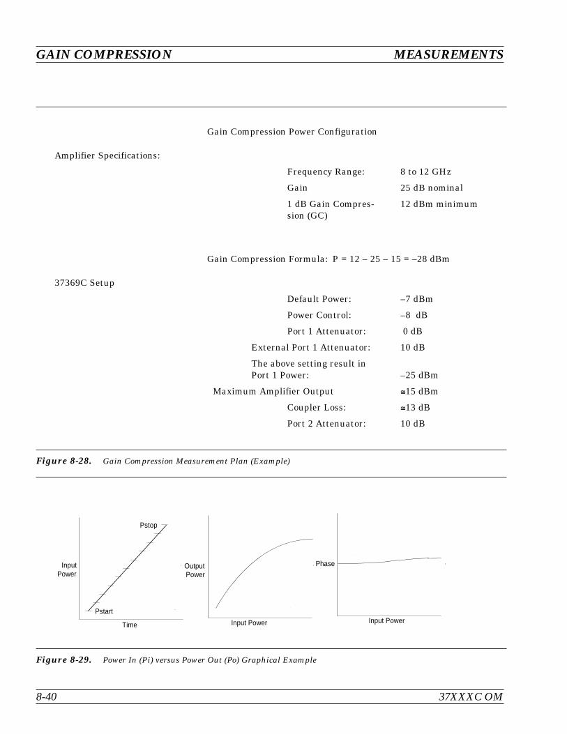
GAIN COMPRESSION MEASUREMENTS
8-40 37XXXC OM
Gain Compression Power Configuration
Amplifier Specifications:
Frequency Range: 8 to 12 GHz
Gain 25 dB nominal
1 dB Gain Compres-sion (GC)
12 dBm minimum
Gain Compression Formula: P = 12 – 25 – 15 = –28 dBm
37369C Setup
Default Power: –7 dBm
Power Control: –8 dB
Port 1 Attenuator: 0 dB
External Port 1 Attenuator: 10 dB
The above setting result inPort 1 Power: –25 dBm
Maximum Amplifier Output 15 dBm
Coupler Loss: 13 dB
Port 2 Attenuator: 10 dB
Figure 8-28. Gain Compression Measurement Plan (Example)
OutputPower
Input Power
Phase
Input Power
InputPower
Time
Pstart
Pstop
Figure 8-29. Power In (Pi) versus Power Out (Po) Graphical Example

Errors can result if the proper correction factor isnot applied by the power meter, as shown below.
Correction Factor (%) Error (dB)
1 0.043
3 0.128
5 0.212
10 0.414
It is desirable to set the power control at or near theminimum (this varies from -20 to -30 dB, dependingupon model) when establishing P, as this providesthe full ALC range for a power sweep.
The vector error correction available in VNAs is de-pendent upon ratioed S-parameter measurements.Power is measured using a single, unratioed chan-nel; therefore, when power is being measured errorcorrection is turned off.
Swept Power GainCompression
A swept power test is done at a CW frequency. Theinput power will be increased with a step sweepstarting at Pstart and ending at Pstop. The step in-crement is also user defined. This lets you observethe conventional Po vs. Pi presentation or a displayof Phase vs. Pi. Figure 8-29 (previous page) illus-trates this process. The SPGC process is imple-mented in the 37XXXC by following the procedurethat begins on page 8-43. The test setup required forthis procedure is shown in Figure 8-30 (page 8-42).
Swept Frequency GainCompression
This is a manual procedure that provides a normal-ized amplifier response as a function of frequency atPstart and manually increases the input powerwhile observing the decrease in gain as the ampli-fier goes into compression. This lets you easily ob-serve the most critical compression frequency of abroadband amplifier. The SFGC process is imple-mented in the 37XXXC by following the procedurethat begins on page 8-52. The test setup required forthis procedure is shown in Figure 8-30 (followingpage).
37XXXC OM 8-41
MEASUREMENTS GAIN COMPRESSION
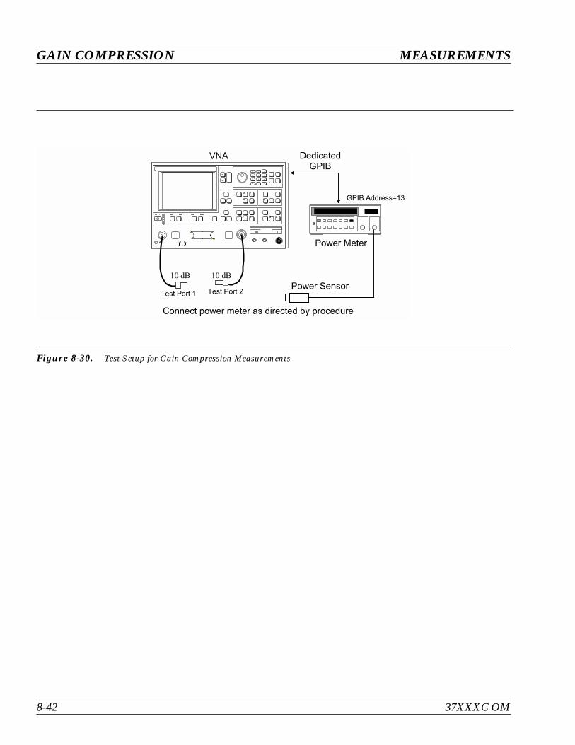
GAIN COMPRESSION MEASUREMENTS
8-42 37XXXC OM
7 8 9
4 5 6
1 2 3
0 . -
Figure 8-30. Test Setup for Gain Compression Measurements

Swept Power Gain Compression MeasurementThe following procedures describes the Swept Power Gain Compres-sion Measurement.
Step 1. Press the Appl key.
NOTEA 12-Term S-parameter calibration is notnecessary for gain compression calibrationand measurement. If such a calibration is inplace, it will be disabled during the gaincompression operation.
Step 2. Move cursor to SWEPT POWER GAIN COM-PRESSION and press Enter, when menu APPL (topleft) appears.
Step 3. When menu GC2 (bottom left) appears, follow the di-rections that appear adjacent to the menu, as de-scribed below:
Move cursor to SET FREQUENCIES, press Enterand select from 1 to 10 frequencies.
Enter the frequency value, press a terminator key (e.g.GHz/103/s/m), then Enter to add the frequency to thelist.
NOTEThe number of frequencies and step size,that is entered later, directly affect the timerequired for Linear Power Calibration, in alater step.
37XXXC OM 8-43
MEASUREMENTS GAIN COMPRESSION
MENU APPL
ADAPTER REMOVAL
SWEPT FREQUENCYGAIN COMPRESSION
SWEPT POWERGAIN COMPRESSION
E/O MEASUREMENTS
O/E MEASUREMENTS
MERGE CAL FILES
PRESS <ENTER>TO SELECT
MENU GC2
SWEPT POWERGAIN COMPRESSION
SET FREQUENCIES
P START–25.00 dBm
P STOP–5.00 dBm
STEP SIZE1.00 dB
ATTENUATION
GAIN COMPRESSIONPOINT (MAX REF)
1.00 dB
NOMINAL OFFSET0.00 dB
MORE
PRESS <ENTER>TO SELECT
Appl
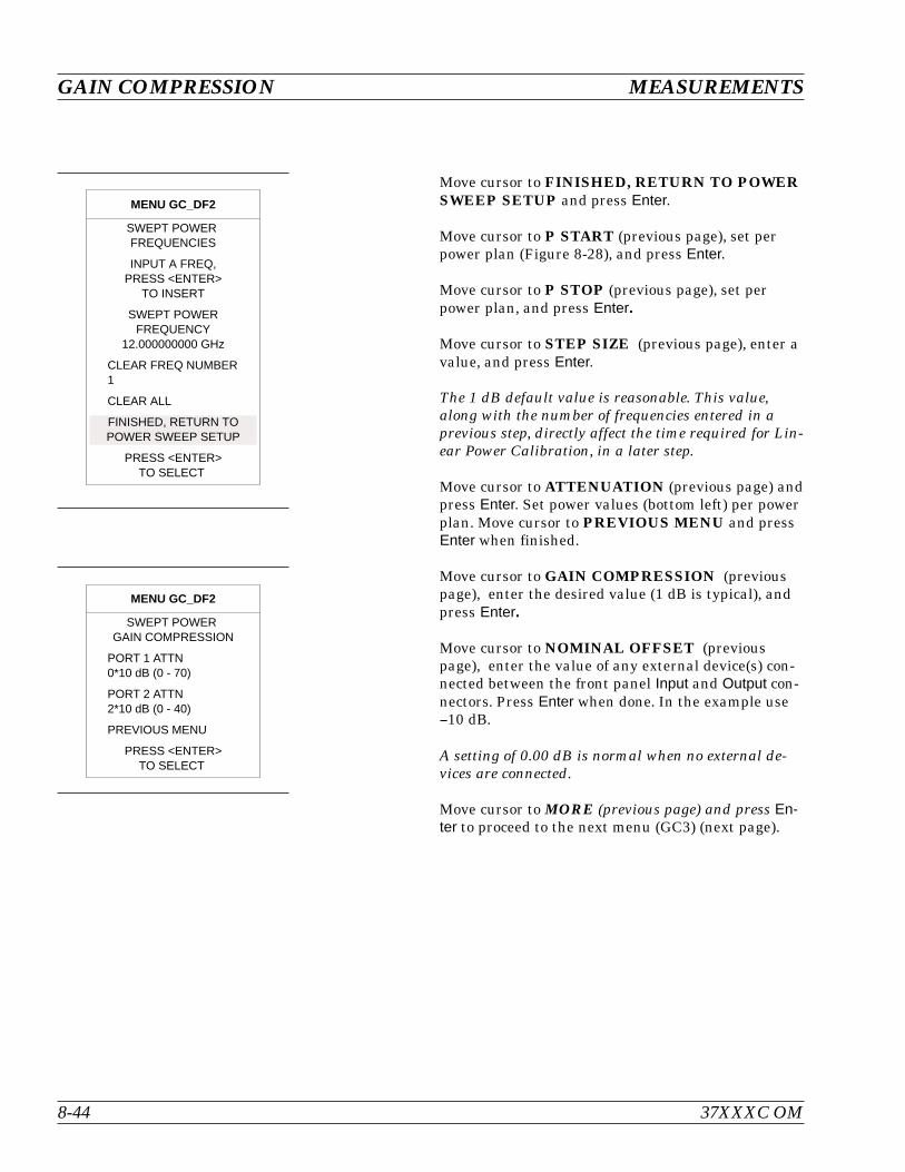
Move cursor to FINISHED, RETURN TO POWERSWEEP SETUP and press Enter.
Move cursor to P START (previous page), set perpower plan (Figure 8-28), and press Enter.
Move cursor to P STOP (previous page), set perpower plan, and press Enter.
Move cursor to STEP SIZE (previous page), enter avalue, and press Enter.
The 1 dB default value is reasonable. This value,along with the number of frequencies entered in aprevious step, directly affect the time required for Lin-ear Power Calibration, in a later step.
Move cursor to ATTENUATION (previous page) andpress Enter. Set power values (bottom left) per powerplan. Move cursor to PREVIOUS MENU and pressEnter when finished.
Move cursor to GAIN COMPRESSION (previouspage), enter the desired value (1 dB is typical), andpress Enter.
Move cursor to NOMINAL OFFSET (previouspage), enter the value of any external device(s) con-nected between the front panel Input and Output con-nectors. Press Enter when done. In the example use10 dB.
A setting of 0.00 dB is normal when no external de-vices are connected.
Move cursor to MORE (previous page) and press En-ter to proceed to the next menu (GC3) (next page).
GAIN COMPRESSION MEASUREMENTS
8-44 37XXXC OM
MENU GC_DF2
SWEPT POWERFREQUENCIES
INPUT A FREQ,PRESS <ENTER>
TO INSERT
SWEPT POWERFREQUENCY
12.000000000 GHz
CLEAR FREQ NUMBER1
CLEAR ALL
FINISHED, RETURN TOPOWER SWEEP SETUP
PRESS <ENTER>TO SELECT
MENU GC_DF2
SWEPT POWERGAIN COMPRESSION
PORT 1 ATTN0*10 dB (0 - 70)
PORT 2 ATTN2*10 dB (0 - 40)
PREVIOUS MENU
PRESS <ENTER>TO SELECT
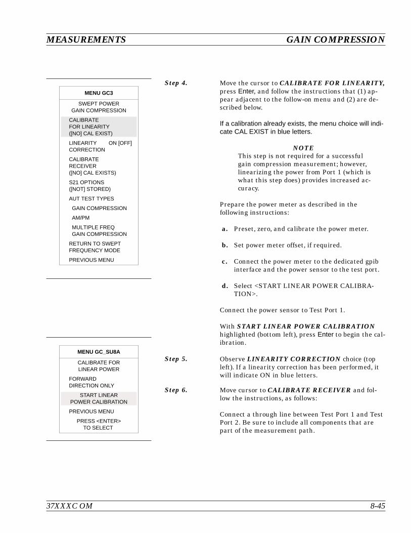
Step 4. Move the cursor to CALIBRATE FOR LINEARITY,press Enter, and follow the instructions that (1) ap-pear adjacent to the follow-on menu and (2) are de-scribed below.
If a calibration already exists, the menu choice will indi-cate CAL EXIST in blue letters.
NOTEThis step is not required for a successfulgain compression measurement; however,linearizing the power from Port 1 (which iswhat this step does) provides increased ac-curacy.
Prepare the power meter as described in thefollowing instructions:
a. Preset, zero, and calibrate the power meter.
b. Set power meter offset, if required.
c. Connect the power meter to the dedicated gpibinterface and the power sensor to the test port.
d. Select <START LINEAR POWER CALIBRA-TION>.
Connect the power sensor to Test Port 1.
With START LINEAR POWER CALIBRATIONhighlighted (bottom left), press Enter to begin the cal-ibration.
Step 5. Observe LINEARITY CORRECTION choice (topleft). If a linearity correction has been performed, itwill indicate ON in blue letters.
Step 6. Move cursor to CALIBRATE RECEIVER and fol-low the instructions, as follows:
Connect a through line between Test Port 1 and TestPort 2. Be sure to include all components that arepart of the measurement path.
37XXXC OM 8-45
MEASUREMENTS GAIN COMPRESSION
MENU GC3
SWEPT POWERGAIN COMPRESSION
CALIBRATEFOR LINEARITY([NO] CAL EXIST)
LINEARITY ON [OFF]CORRECTION
CALIBRATERECEIVER([NO] CAL EXISTS)
S21 OPTIONS([NOT] STORED)
AUT TEST TYPES
GAIN COMPRESSION
AM/PM
MULTIPLE FREQGAIN COMPRESSION
RETURN TO SWEPTFREQUENCY MODE
PREVIOUS MENU
MENU GC_SU8A
CALIBRATE FORLINEAR POWER
FORWARDDIRECTION ONLY
START LINEARPOWER CALIBRATION
PREVIOUS MENU
PRESS <ENTER>TO SELECT
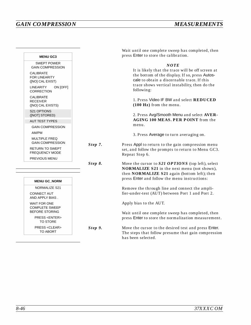
Wait until one complete sweep has completed, thenpress Enter to store the calibration.
NOTEIt is likely that the trace will be off screen atthe bottom of the display. If so, press Autos-cale to obtain a discernable trace. If thistrace shows vertical instability, then do thefollowing:
1. Press Video IF BW and select REDUCED(100 Hz) from the menu.
2. Press Avg/Smooth Menu and select AVER-AGING 100 MEAS. PER POINT from themenu.
3. Press Average to turn averaging on.
Step 7. Press Appl to return to the gain compression menuset, and follow the prompts to return to Menu GC3.Repeat Step 6.
Step 8. Move the cursor to S21 OPTIONS (top left), selectNORMALIZE S21 in the next menu (not shown),then NORMALIZE S21 again (bottom left); thenpress Enter and follow the menu instructions:
Remove the through line and connect the ampli-fier-under-test (AUT) between Port 1 and Port 2.
Apply bias to the AUT.
Wait until one complete sweep has completed, thenpress Enter to store the normalization measurement.
Step 9. Move the cursor to the desired test and press Enter.The steps that follow presume that gain compressionhas been selected.
8-46 37XXXC OM
GAIN COMPRESSION MEASUREMENTS
MENU GC_NORM
NORMALIZE S21
CONNECT AUTAND APPLY BIAS .
WAIT FOR ONECOMPLETE SWEEPBEFORE STORING
PRESS <ENTER>TO STORE
PRESS <CLEAR>TO ABORT
MENU GC3
SWEPT POWERGAIN COMPRESSION
CALIBRATEFOR LINEARITY([NO] CAL EXIST)
LINEARITY ON [OFF]CORRECTION
CALIBRATERECEIVER([NO] CAL EXISTS)
S21 OPTIONS([NOT] STORED)
AUT TEST TYPES
GAIN COMPRESSION
AM/PM
MULTIPLE FREQGAIN COMPRESSION
RETURN TO SWEPTFREQUENCY MODE
PREVIOUS MENU
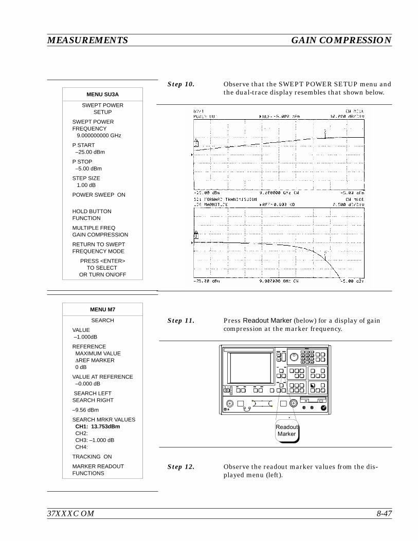
Step 10. Observe that the SWEPT POWER SETUP menu andthe dual-trace display resembles that shown below.
Step 11. Press Readout Marker (below) for a display of gaincompression at the marker frequency.
Step 12. Observe the readout marker values from the dis-played menu (left).
37XXXC OM 8-47
MEASUREMENTS GAIN COMPRESSION
Readout
Marker
MENU M7
SEARCH
VALUE–1.000dB
REFERENCEMAXIMUM VALUEREF MARKER0 dB
VALUE AT REFERENCE–0.000 dB
SEARCH LEFTSEARCH RIGHT
–9.56 dBm
SEARCH MRKR VALUESCH1: 13.753dBmCH2:CH3: –1.000 dBCH4:
TRACKING ON
MARKER READOUTFUNCTIONS
MENU SU3A
SWEPT POWERSETUP
SWEPT POWERFREQUENCY
9.000000000 GHz
P START–25.00 dBm
P STOP–5.00 dBm
STEP SIZE1.00 dB
POWER SWEEP ON
HOLD BUTTONFUNCTION
MULTIPLE FREQGAIN COMPRESSION
RETURN TO SWEPTFREQUENCY MODE
PRESS <ENTER>TO SELECT
OR TURN ON/OFF
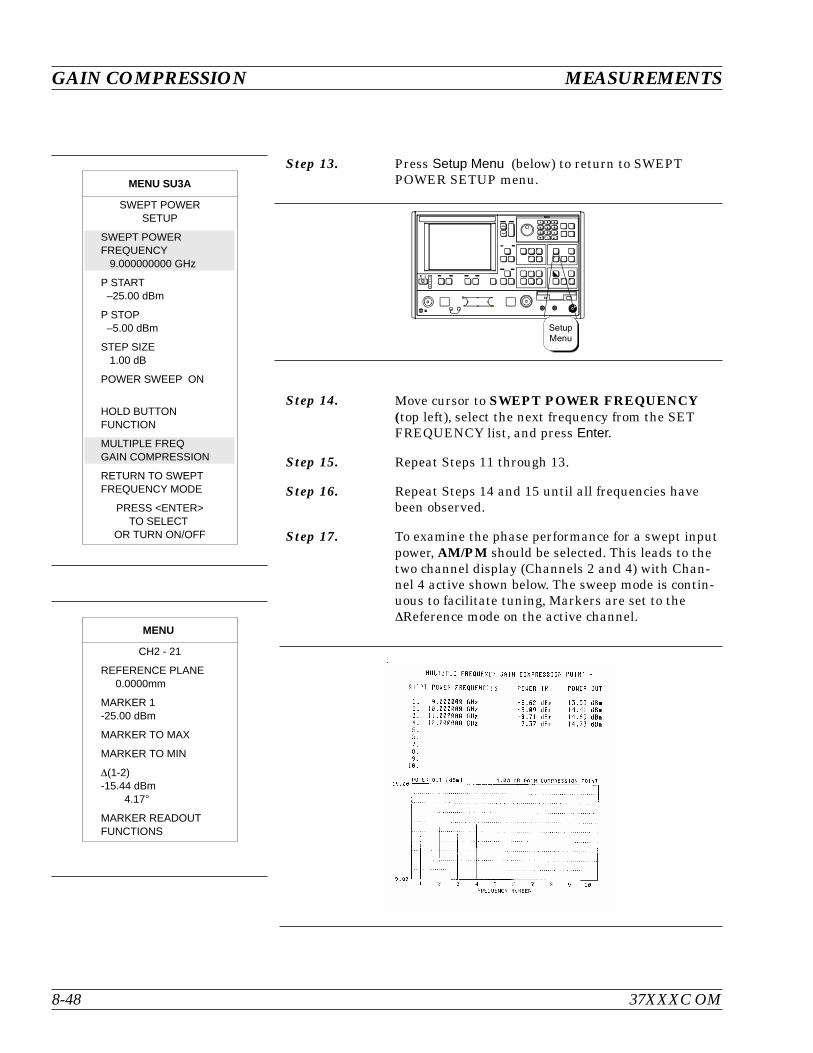
Step 13. Press Setup Menu (below) to return to SWEPTPOWER SETUP menu.
Step 14. Move cursor to SWEPT POWER FREQUENCY(top left), select the next frequency from the SETFREQUENCY list, and press Enter.
Step 15. Repeat Steps 11 through 13.
Step 16. Repeat Steps 14 and 15 until all frequencies havebeen observed.
Step 17. To examine the phase performance for a swept inputpower, AM/PM should be selected. This leads to thetwo channel display (Channels 2 and 4) with Chan-nel 4 active shown below. The sweep mode is contin-uous to facilitate tuning, Markers are set to theReference mode on the active channel.
GAIN COMPRESSION MEASUREMENTS
8-48 37XXXC OM
MENU
CH2 - 21
REFERENCE PLANE0.0000mm
MARKER 1-25.00 dBm
MARKER TO MAX
MARKER TO MIN
(1-2)-15.44 dBm
4.17
MARKER READOUTFUNCTIONS
Setup
Menu
MENU SU3A
SWEPT POWERSETUP
SWEPT POWERFREQUENCY
9.000000000 GHz
P START–25.00 dBm
P STOP–5.00 dBm
STEP SIZE1.00 dB
POWER SWEEP ON
HOLD BUTTONFUNCTION
MULTIPLE FREQGAIN COMPRESSION
RETURN TO SWEPTFREQUENCY MODE
PRESS <ENTER>TO SELECT
OR TURN ON/OFF
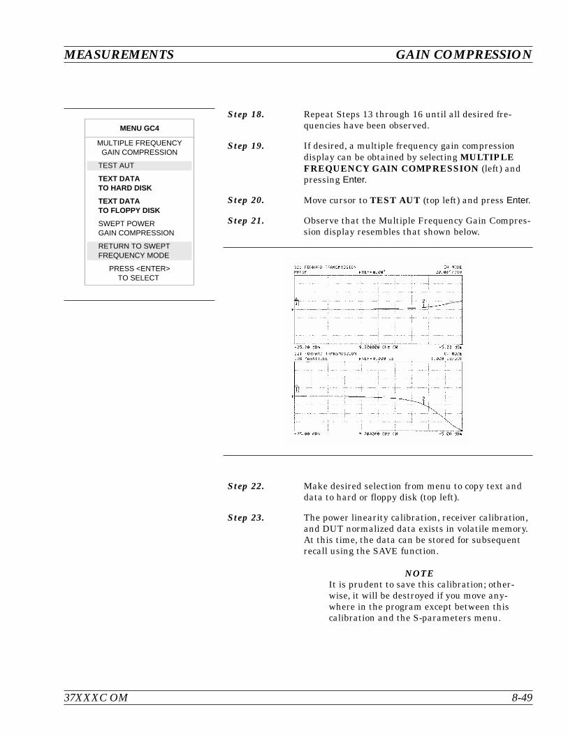
Step 18. Repeat Steps 13 through 16 until all desired fre-quencies have been observed.
Step 19. If desired, a multiple frequency gain compressiondisplay can be obtained by selecting MULTIPLEFREQUENCY GAIN COMPRESSION (left) andpressing Enter.
Step 20. Move cursor to TEST AUT (top left) and press Enter.
Step 21. Observe that the Multiple Frequency Gain Compres-sion display resembles that shown below.
Step 22. Make desired selection from menu to copy text anddata to hard or floppy disk (top left).
Step 23. The power linearity calibration, receiver calibration,and DUT normalized data exists in volatile memory.At this time, the data can be stored for subsequentrecall using the SAVE function.
NOTEIt is prudent to save this calibration; other-wise, it will be destroyed if you move any-where in the program except between thiscalibration and the S-parameters menu.
37XXXC OM 8-49
MEASUREMENTS GAIN COMPRESSION
MENU GC4
MULTIPLE FREQUENCYGAIN COMPRESSION
TEST AUT
TEXT DATATO HARD DISK
TEXT DATATO FLOPPY DISK
SWEPT POWERGAIN COMPRESSION
RETURN TO SWEPTFREQUENCY MODE
PRESS <ENTER>TO SELECT

Step 24. Move cursor to RETURN TO SWEPT FRE-QUENCY MODE and press Enter to exit the gaincompression mode.
NOTEWhen exiting the Swept Frequency Power Gain Compres-sion mode, the DUT should be turned off, unless the userhas selected the proper attenuator settings for standardswept frequency (S-parameter) operation.
GAIN COMPRESSION MEASUREMENTS
8-50 37XXXC OM
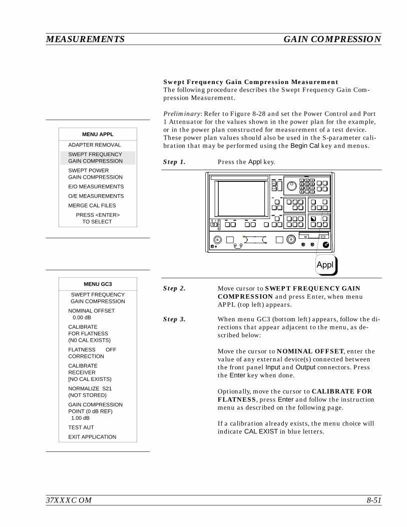
Swept Frequency Gain Compression MeasurementThe following procedure describes the Swept Frequency Gain Com-pression Measurement.
Preliminary: Refer to Figure 8-28 and set the Power Control and Port1 Attenuator for the values shown in the power plan for the example,or in the power plan constructed for measurement of a test device.These power plan values should also be used in the S-parameter cali-bration that may be performed using the Begin Cal key and menus.
Step 1. Press the Appl key.
Step 2. Move cursor to SWEPT FREQUENCY GAINCOMPRESSION and press Enter, when menuAPPL (top left) appears.
Step 3. When menu GC3 (bottom left) appears, follow the di-rections that appear adjacent to the menu, as de-scribed below:
Move the cursor to NOMINAL OFFSET, enter thevalue of any external device(s) connected betweenthe front panel Input and Output connectors. Pressthe Enter key when done.
Optionally, move the cursor to CALIBRATE FORFLATNESS, press Enter and follow the instructionmenu as described on the following page.
If a calibration already exists, the menu choice willindicate CAL EXIST in blue letters.
37XXXC OM 8-51
MEASUREMENTS GAIN COMPRESSION
MENU APPL
ADAPTER REMOVAL
SWEPT FREQUENCYGAIN COMPRESSION
SWEPT POWERGAIN COMPRESSION
E/O MEASUREMENTS
O/E MEASUREMENTS
MERGE CAL FILES
PRESS <ENTER>TO SELECT
MENU GC3
SWEPT FREQUENCYGAIN COMPRESSION
NOMINAL OFFSET0.00 dB
CALIBRATEFOR FLATNESS(N0 CAL EXISTS)
FLATNESS OFFCORRECTION
CALIBRATERECEIVER[NO CAL EXISTS)
NORMALIZE S21(NOT STORED)
GAIN COMPRESSIONPOINT (0 dB REF)1.00 dB
TEST AUT
EXIT APPLICATION
Appl
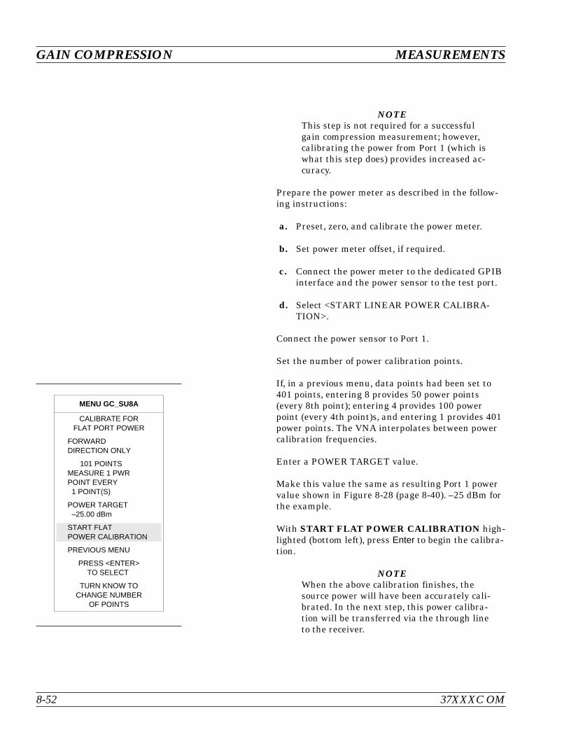
NOTEThis step is not required for a successfulgain compression measurement; however,calibrating the power from Port 1 (which iswhat this step does) provides increased ac-curacy.
Prepare the power meter as described in the follow-ing instructions:
a. Preset, zero, and calibrate the power meter.
b. Set power meter offset, if required.
c. Connect the power meter to the dedicated GPIBinterface and the power sensor to the test port.
d. Select <START LINEAR POWER CALIBRA-TION>.
Connect the power sensor to Port 1.
Set the number of power calibration points.
If, in a previous menu, data points had been set to401 points, entering 8 provides 50 power points(every 8th point); entering 4 provides 100 powerpoint (every 4th point)s, and entering 1 provides 401power points. The VNA interpolates between powercalibration frequencies.
Enter a POWER TARGET value.
Make this value the same as resulting Port 1 powervalue shown in Figure 8-28 (page 8-40). –25 dBm forthe example.
With START FLAT POWER CALIBRATION high-lighted (bottom left), press Enter to begin the calibra-tion.
NOTEWhen the above calibration finishes, thesource power will have been accurately cali-brated. In the next step, this power calibra-tion will be transferred via the through lineto the receiver.
GAIN COMPRESSION MEASUREMENTS
8-52 37XXXC OM
MENU GC_SU8A
CALIBRATE FORFLAT PORT POWER
FORWARDDIRECTION ONLY
101 POINTSMEASURE 1 PWRPOINT EVERY1 POINT(S)
POWER TARGET–25.00 dBm
START FLATPOWER CALIBRATION
PREVIOUS MENU
PRESS <ENTER>TO SELECT
TURN KNOW TOCHANGE NUMBER
OF POINTS
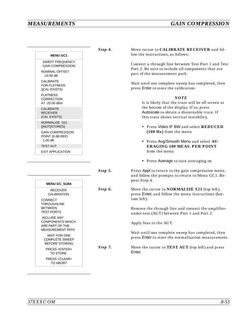
Step 4. Move cursor to CALIBRATE RECEIVER and fol-low the instructions, as follows:
Connect a through line between Test Port 1 and TestPort 2. Be sure to include all components that arepart of the measurement path.
Wait until one complete sweep has completed, thenpress Enter to store the calibration.
NOTEIt is likely that the trace will be off screen atthe bottom of the display. If so, pressAutoscale to obtain a discernable trace. Ifthis trace shows vertical instability,
Press Video IF BW and select REDUCED(100 Hz) from the menu
Press Avg/Smooth Menu and select AV-ERAGING 100 MEAS. PER POINTfrom the menu
Press Average to turn averaging on
Step 5. Press Appl to return to the gain compression menu,and follow the prompts to return to Menu GC1. Re-peat Step 4.
Step 6. Move the cursor to NORMALIZE S21 (top left),press Enter, and follow the menu instructions (bot-tom left):
Remove the through line and connect the amplifier-under-test (AUT) between Port 1 and Port 2.
Apply bias to the AUT.
Wait until one complete sweep has completed, thenpress Enter to store the normalization measurement.
Step 7. Move the cursor to TEST AUT (top left) and pressEnter.
37XXXC OM 8-53
MEASUREMENTS GAIN COMPRESSION
MENU GC1
SWEPT FREQUENCYGAIN COMPRESSION
NOMINAL OFFSET-10.00 dB
CALIBRATEFOR FLATNESS(]CAL EXISTS)
FLATNESSCORRECTIONAT -25.00 dBm
CALIBRATERECEIVER(CAL EXISTS)
NORMALIZE S21([NOT]STORED)
GAIN COMPRESSIONPOINT (0 dB REF)1.00 dB
TEST AUT
EXIT APPLICATION
MENU GC_SU8A
RECEIVERCALIBRATION
CONNECTTHROUGHLINEBETWEENTEST PORTS
INCLUDE ANYCOMPONENTS WHICHARE PART OF THEMEASUREMENT PATH
WAIT FOR ONECOMPLETE SWEEPBEFORE STORING
PRESS <ENTER>TO STORE
PRESS <CLEAR>TO ABORT
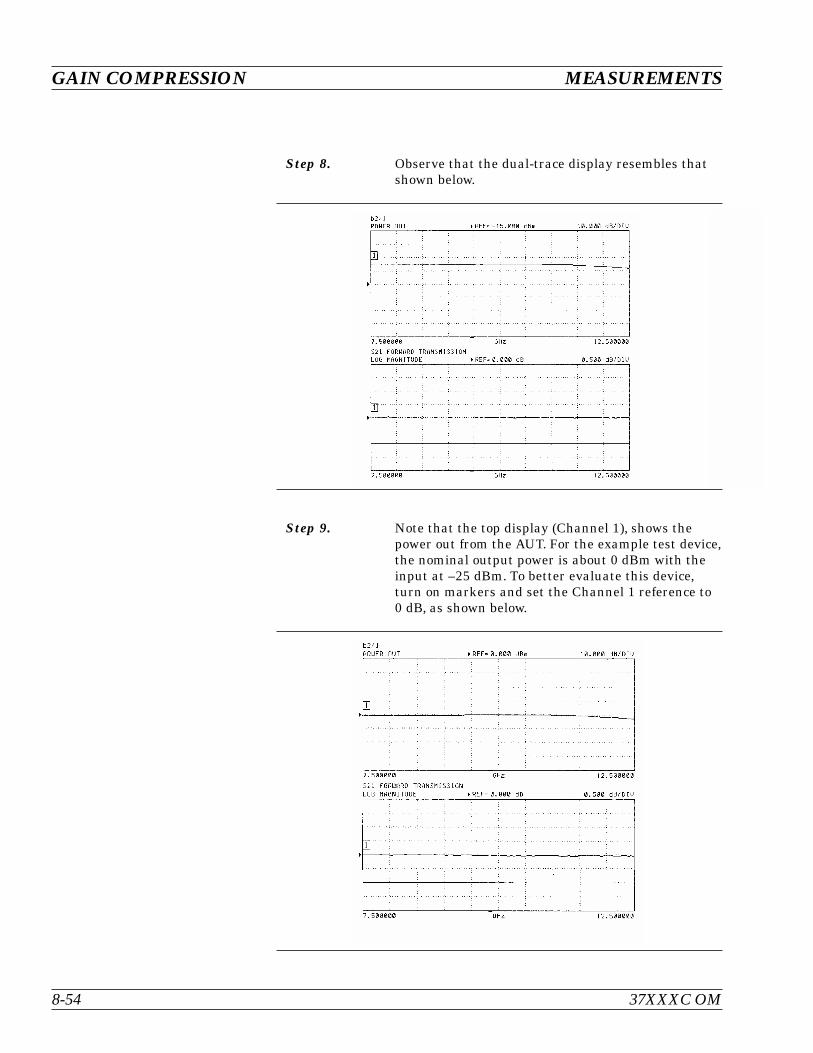
Step 8. Observe that the dual-trace display resembles thatshown below.
Step 9. Note that the top display (Channel 1), shows thepower out from the AUT. For the example test device,the nominal output power is about 0 dBm with theinput at –25 dBm. To better evaluate this device,turn on markers and set the Channel 1 reference to0 dB, as shown below.
GAIN COMPRESSION MEASUREMENTS
8-54 37XXXC OM
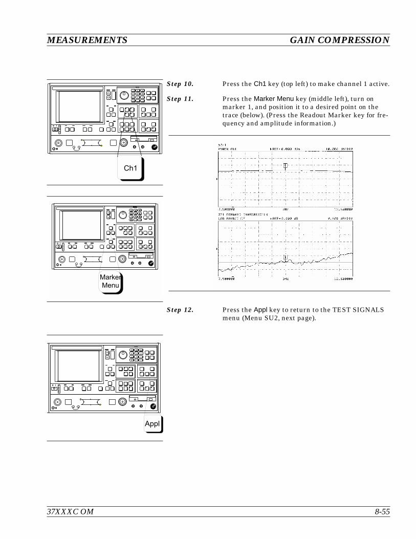
Step 10. Press the Ch1 key (top left) to make channel 1 active.
Step 11. Press the Marker Menu key (middle left), turn onmarker 1, and position it to a desired point on thetrace (below). (Press the Readout Marker key for fre-quency and amplitude information.)
Step 12. Press the Appl key to return to the TEST SIGNALSmenu (Menu SU2, next page).
37XXXC OM 8-55
MEASUREMENTS GAIN COMPRESSION
- B G
> 4 6
:
7 . 8
#
I
MarkerMenu
- B G
> 4 6
:
7 . 8
#

Step 13. Press the Setup Menu key (top left), select POWERCONTROL (bottom left) and increase the valuewhile observing compression in channel 3 (S21).
NOTEThe rotary knob or the keypad can be usedto set the POWER CONTROL value. In us-ing the rotary knob, the displayed valuedoes not change in real time with movementof the control. Change occurs after the rota-tion of the knob is complete.
Step 14. Press the Marker Menu key again, and observe thedisplayed Ch 3 trace and the marker values from thedisplayed menu (below).
Step 15. The power linearity calibration, receiver calibration,and DUT normalized data exists in volatile memory.At this time, the data can be stored for subsequentrecall using the SAVE function.
NOTEIt is prudent to save this calibration; other-wise, it will be destroyed if you move any-where in the program except between thiscalibration and the S-parameters menu.
GAIN COMPRESSION MEASUREMENTS
8-56 37XXXC OM
Setup
Menu
MENU SU2
MARKER 1ALL DISPLAYED
CHANNELS
CH 1 - S11 USER10.000000 GHz
12.06 dBm
CH 2 - S12
CH 3 - S2110.000000 GHz
-0.992 dB
CH 4 - S21
MARKER TO MAXMARKER TO MIN
MARKER READOUTFUNCTIONS
PRESS <ENTER>TO SELECT
MENU SU2
TEST SIGNALS
POWER CONTROL5.47 dB
0 TO –20.00 dB
PORT 1 ATTN0 * 10 dB (0 – 70)
PORT 1 POWER–1.53 dBm
PORT 2 ATTN0 * 10 dB (0 –40)
CALIBRATEFOR FLATNESS(CAL EXISTS)
FLATNESSCORRECTIONAT –11.53 dBm
PORT 2 POWER0.00 dBm
EXIT APPLICATION
PRESS <ENTER>TO SELECT
OR TURN ON/OFF

Step 16. Move cursor to RETURN TO SWEPTFREQUENCY MODE and press Enter to exit thegain compression mode.
Step 17. Press the Appl key to return to the TEST SIGNALSmenu (left), highlight EXIT APPLICATION andpress Enter to exit the gain compression measure-ment area.
CAUTIONWhen exiting the Swept Frequency Power Gain Compres-sion mode, the DUT should be turned off, unless the userhas selected the proper attenuator settings for standardswept frequency (S-parameter) operation.
37XXXC OM 8-57
MEASUREMENTS GAIN COMPRESSION
MENU SU2
TEST SIGNALS
POWER CONTROL5.47 dB
0 TO –20.00 dB
PORT 1 ATTN0 * 10 dB (0 – 70)
PORT 1 POWER–1.53 dBm
PORT 2 ATTN0 * 10 dB (0 –40)
CALIBRATEFOR FLATNESS(CAL EXISTS)
FLATNESSCORRECTIONAT –11.53 dBm
PORT 2 POWER0.00 dBm
EXIT APPLICATION
PRESS <ENTER>TO SELECT
OR TURN ON/OFF
8-9 RECEIVER MODE The Receiver Mode provides three distinct modes of operation:
Sweep/Source Lock mode, phase locks the internal source
Synthesizer/Tracking mode, lets the receiver track a 67XXB,68XXXB, or 69XXXA synthesizer
Set-On mode, lets the VNA operate as a tuned receiver
Source Lock Mode The Source Lock mode enables the 37XXXC to phase lock to its inter-nal source.
Tracking Mode In the Tracking Mode, the 37XXXC steers its second local oscillatorfrequency and phase signal so as to phase-lock itself to the referencesignal. Typically the source is a synthesizer, since it must be accurateto better than 10 MHz for the 37XXXC to achieve lock. Due to the in-herent resolution of the 37XXXC, frequency resolution is limited to 1kHz intervals. If Option 3 is installed frequency resolution is limited to1 Hz.
For receive frequencies outside the indicated test set range, the use ofexternal mixers and a synthesizer is required. Dual Source Control isrequired in this case.
Set-on Mode In the Set-On mode, the source lock circuitry of the 37XXXC is com-pletely by-passed. Reference signals are no longer necessary for systemoperation. This allows all of the 37XXXC samplers to operate overtheir full dynamic range. As a result, the source and the 37XXXC mustbe locked to the same 10 MHz time base, otherwise coherent detectionis not possible. Only synthesized sources may be used in this mode.Dual source control is required.
Due to the inherent resolution of the 37XXXC local oscillators, fre-quency resolution is limited to 1 kHz intervals over the frequencyrange of the VNA. If Option 3 is installed, frequency resolution is lim-ited to 1 Hz.
RECEIVER MODE MEASUREMENTS
8-58 37XXXC OM

Receiver Mode BlockDiagram
The block diagram shown in Figure 8-31 shows how the system is con-figured for all of the possible modes of operation. With the switches setas shown, the system operates in the Set-On mode. LO1 and LO2 arepre-set to allow only a prescribed signal to be detected by the synchro-nous detector. With the switch in SOURCE LOCK position the systemis operating in the internal source-lock mode. With the switch in theTRACKING position, the system is in the synthesizer tracking mode.
Receiver Mode Menus The menus associated with the Receiver Mode are described in the al-phabetical listing (Appendix A) under their call sign: RCV1, RCV2,RCV3, etc.
Procedure, Receiver ModeOperation
A detailed procedure for operation using the Receiver Mode option isprovided in the following pages.
37XXXC OM 8-59
MEASUREMENTS RECEIVER MODE
SOURCE LOCK ANALOG LOCK SIGNAL
SAMPLER
1ST L.O. 2ND L.O.
TRACKINGSET ON
10 MHz(SYNTHESIZER) TRACKING
SOURCE LOCK/SET ON
10 MHz
10 MHz
10 MHz
REAL
IMAGINARY
2.5 MHz
3RD L.O.2.42 MHz
4TH L.O.80 KHz
10 MHz 10 MHz
SYNCHRONOUSDETECTOR
PLLPLL
RF MEASURECIRCUIT
Figure 8-31. 37XXXC Phase Lock Modes
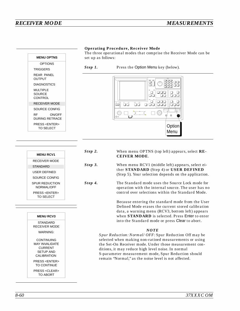
Operating Procedure, Receiver ModeThe three operational modes that comprise the Receiver Mode can beset up as follows:
Step 1. Press the Option Menu key (below).
Step 2. When menu OPTNS (top left) appears, select RE-CEIVER MODE.
Step 3. When menu RCV1 (middle left) appears, select ei-ther STANDARD (Step 4) or USER DEFINED(Step 5). Your selection depends on the application.
Step 4. The Standard mode uses the Source Lock mode foroperation with the internal source. The user has nocontrol over selections within the Standard Mode.
Because entering the standard mode from the UserDefined Mode erases the current stored calibrationdata, a warning menu (RCV3, bottom left) appearswhen STANDARD is selected. Press Enter to enterinto the Standard mode or press Clear to abort.
NOTESpur Reduction: Normal/OFF: Spur Reduction Off may beselected when making non-ratioed measurements or usingthe Set-On Receiver mode. Under those measurement con-ditions, it may reduce high level noise. In normalS-parameter measurement mode, Spur Reduction shouldremain “Normal,” as the noise level is not affected.
RECEIVER MODE MEASUREMENTS
8-60 37XXXC OM
OptionMenu
MENU RCV3
STANDARDRECEIVER MODE
WARNING:
CONTINUINGMAY INVALIDATE
CURRENTSETUP AND
CALIBRATION
PRESS <ENTER>TO CONTINUE
PRESS <CLEAR>TO ABORT
MENU RCV1
RECEIVER MODE
STANDARD
USER DEFINED
SOURCE CONFIG
SPUR REDUCTIONNORMAL/OFF
PRESS <ENTER>TO SELECT
MENU OPTNS
OPTIONS
TRIGGERS
REAR PANELOUTPUT
DIAGNOSTICS
MULTIPLESOURCECONTROL
RECEIVER MODE
SOURCE CONFIG
RF ON/OFFDURING RETRACE
PRESS <ENTER>TO SELECT
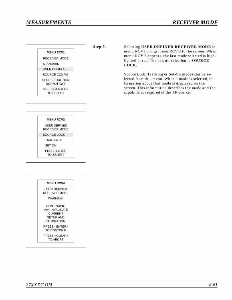
Step 5. Selecting USER DEFINED RECEIVER MODE inmenu RCV1 brings menu RCV 2 to the screen. Whenmenu RCV 2 appears, the last mode selected is high-lighted in red. The default selection is SOURCELOCK.
Source Lock, Tracking or Set-On modes can be se-lected from this menu. When a mode is selected, in-formation about that mode is displayed on thescreen. This information describes the mode and thecapabilities required of the RF source.
MEASUREMENTS RECEIVER MODE
37XXXC OM 8-61
MENU RCV1
RECEIVER MODE
STANDARD
USER DEFINED
SOURCE CONFIG
SPUR REDUCTIONNORMAL/OFF
PRESS <ENTER>TO SELECT
MENU RCV2
USER DEFINEDRECEIVER MODE
SOURCE LOCK
TRACKING
SET ON
PRESS ENTERTO SELECT
MENU RCV4
USER DEFINEDRECEIVER MODE
WARNING:
CONTINUINGMAY INVALIDATE
CURRENTSETUP AND
CALIBRATION
PRESS <ENTER>TO CONTINUE
PRESS <CLEAR>TO ABORT
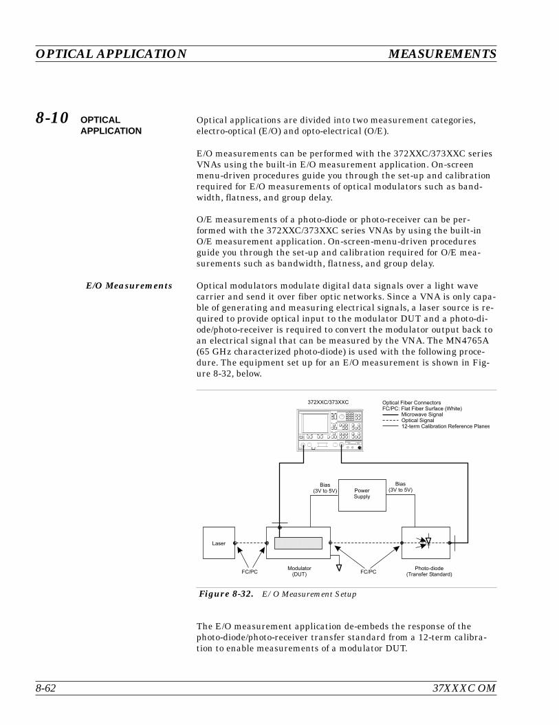
8-10 OPTICALAPPLICATION
Optical applications are divided into two measurement categories,electro-optical (E/O) and opto-electrical (O/E).
E/O measurements can be performed with the 372XXC/373XXC seriesVNAs using the built-in E/O measurement application. On-screenmenu-driven procedures guide you through the set-up and calibrationrequired for E/O measurements of optical modulators such as band-width, flatness, and group delay.
O/E measurements of a photo-diode or photo-receiver can be per-formed with the 372XXC/373XXC series VNAs by using the built-inO/E measurement application. On-screen-menu-driven proceduresguide you through the set-up and calibration required for O/E mea-surements such as bandwidth, flatness, and group delay.
E/O Measurements Optical modulators modulate digital data signals over a light wavecarrier and send it over fiber optic networks. Since a VNA is only capa-ble of generating and measuring electrical signals, a laser source is re-quired to provide optical input to the modulator DUT and a photo-di-ode/photo-receiver is required to convert the modulator output back toan electrical signal that can be measured by the VNA. The MN4765A(65 GHz characterized photo-diode) is used with the following proce-dure. The equipment set up for an E/O measurement is shown in Fig-ure 8-32, below.
The E/O measurement application de-embeds the response of thephoto-diode/photo-receiver transfer standard from a 12-term calibra-tion to enable measurements of a modulator DUT.
OPTICAL APPLICATION MEASUREMENTS
8-62 37XXXC OM
7 8 9
4 5 6
1 2 3
0 . -
Dat a Entr y
Laser
Modulator(DUT)
Photo-diode(Transfer Standard)
PowerSupply
372XXC/373XXC
FC/PC FC/PC
Bias(3V to 5V)
Bias(3V to 5V)
Optical Fiber ConnectorsFC/PC: Flat Fiber Surface (White)
Microwave SignalOptical Signal12-term Calibration Reference Planes
Figure 8-32. E/O Measurement Setup
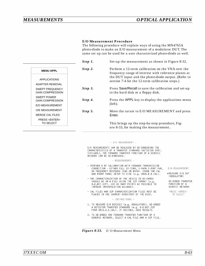
E/O Measurement ProcedureThe following procedure will explain ways of using the MN4765Aphoto-diode to make an E/O measurement of a modulator DUT. Thesame set up can be used for a user characterized photo-diode as well.
Step 1. Set-up the measurement as shown in Figure 8-32.
Step 2. Perform a 12-term calibration on the VNA over thefrequency range of interest with reference planes atthe DUT input and the photo-diode output. (Refer tosection 7-4 for the 12-term calibration steps.)
Step 3. Press Save/Recall to save the calibration and set-upto the hard disk or a floppy disk.
Step 4. Press the APPL key to display the applications menu(left).
Step 5. Move the cursor to E/O MEASUREMENT and pressEnter.
This brings up the step-by-step procedure, Fig-ure 8-33, for making the measurement.
37XXXC OM 8-63
MEASUREMENTS OPTICAL APPLICATION
MENU APPL
APPLICATIONS
ADAPTER REMOVAL
SWEPT FREQUENCYGAIN COMPRESSION
SWEPT POWERGAIN COMPRESSION
E/O MEASUREMENT
O/E MEASUREMENT
MERGE CAL FILES
PRESS <ENTER>TO SELECT
Figure 8-33. E/O Measurement Menu

Step 6. Press Enter to select MEASURE E/O DUT (MODU-LATOR).
This brings up MENU DE3 (top left).
Step 7. Select READ CALIBRATION FILE FROM HARDDISK or READ CALIBRATION FILE FROMFLOPPY DISK depending on where the 12-term cali-bration was saved in Step 3.
This bring up MENU DSK2 (middle left).
Step 8. Select the calibration file and press Enter.
Step 9. Read the S2P file (characterization data file) for thephoto-diode transfer standard. This will de-embedthe photo-diode for an E/O measurement (MENUDE3A, bottom left).
NOTEIf an S2P file is not available, it can be gen-erated from the characterization data pro-vided by the vendor. This is explained onpage 8-71.
The VNA now displays the measurement of the mod-
OPTICAL APPLICATION MEASUREMENTS
8-64 37XXXC OM
MENU DE3
E/O MEASUREMENT
ORIGINAL CAL FILEWITH FWD TRANSCORRECTION
READ CAL FILEFROM HARD DISK
READ CAL FILEFROM FLOPPY DISK
PRESS <ENTER>TO SELECT
PRESS <CLEAR>TO ABORT
MENU DSK2
SELECT FILETO READ
TESTCAL CAL
PREVIOUS MENU
PRESS <ENTER>TO SELECT
PRESS <1> FORPREVIOUS PAGE
PRESS <2> FORNEXT PAGE
MENU DE3A
E/O MEASUREMENT
TRANSFER STANDARDTO BE DE-EMBEDDED(DETECTOR STD)
READ S2P FILEFROM HARD DISK
READ S2P FILEFROM FLOPPY DISK
PRESS <ENTER>TO SELECT
PRESS <CLEAR>TO ABORT
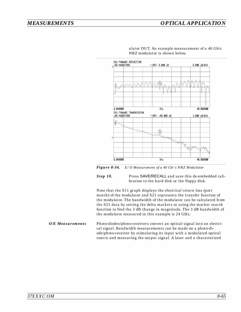
ulator DUT. An example measurement of a 40 Gb/sNRZ modulator is shown below.
Step 10. Press SAVE/RECALL and save this de-embedded cali-bration to the hard disk or the floppy disk.
Note that the S11 graph displays the electrical return loss (portmatch) of the modulator and S21 represents the transfer function ofthe modulator. The bandwidth of the modulator can be calculated fromthe S21 data by setting the delta markers or using the marker searchfunction to find the 3 dB change in magnitude. The 3 dB bandwidth ofthe modulator measured in this example is 24 GHz.
O/E Measurements Photo-diodes/photo-receivers convert an optical signal into an electri-cal signal. Bandwidth measurements can be made on a photo-di-ode/photo-receiver by stimulating its input with a modulated opticalsource and measuring the output signal. A laser and a characterized
37XXXC OM 8-65
MEASUREMENTS OPTICAL APPLICATION
Figure 8-34. E/O Measurement of a 40 Gb/s NRZ Modulator

modulator are required, in addition to the VNA, to make O/E measure-ments. See Figure 8-35, below, for the equipment set-up.
The O/E measurement application de-embeds the response of the mod-ulator transfer standard from a 12-term calibration to enable mea-surements of the photo-diode DUT.
O/E Measurement ProcedureThe following procedure will explain ways of obtaining characteriza-tion data for a modulator and then how to use it to make an O/E mea-surement of a photo-receiver.
Step 1. Set-up the measurement as shown in Figure 8-35,above.
Step 2. Perform a 12-term calibration on the VNA over thefrequency range of interest with reference planes atthe modulator input and the photo-receiver DUToutput. (Refer to section 7-4 for the 12-term calibra-tion steps.)
Step 3. Press Save/Recall to save the calibration and set upto the hard disk or a floppy disk.
OPTICAL APPLICATION MEASUREMENTS
8-66 37XXXC OM
7 8 9
4 5 6
1 2 3
0 . -
Dat a Entr y
Laser
Modulator(Transfer Standard)
Photo-diode(DUT)
PowerSupply
372XXC/373XXC
FC/PC FC/PC
Bias(3V to 5V)
Bias(3V to 5V)
Optical Fiber ConnectorsFC/PC: Flat Fiber Surface (White)
Microwave SignalOptical Signal12-term Calibration Reference Planes
Figure 8-35. O/E Measurement Set-up
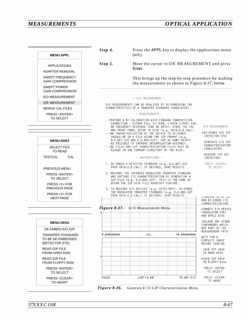
Step 4. Press the APPL key to display the applications menu(left).
Step 5. Move the cursor to O/E MEASUREMENT and pressEnter.
This brings up the step-by-step procedure for makingthe measurement as shown in Figure 8-37, below.
37XXXC OM 8-67
MEASUREMENTS OPTICAL APPLICATION
MENU DSK2
SELECT FILETO READ
TESTCAL CAL
PREVIOUS MENU
PRESS <ENTER>TO SELECT
PRESS <1> FORPREVIOUS PAGE
PRESS <2> FORNEXT PAGE
MENU DE5A
DE-EMBED E/O S2P
TRANSFER STANDARDTO BE DE-EMBEDDED(DETECTOR STD)
READ S2P FILEFROM HARD DISK
READ S2P FILEFROM FLOPPY DISK
PRESS <ENTER>TO SELECT
PRESS <CLEAR>TO ABORT
Figure 8-36. Generate E/O S2P Characterization Menu
Figure 8-37. O/E Measurement Menu
MENU APPL
APPLICATIONS
ADAPTER REMOVAL
SWEPT FREQUENCYGAIN COMPRESSION
SWEPT POWERGAIN COMPRESSION
E/O MEASUREMENT
O/E MEASUREMENT
MERGE CAL FILES
PRESS <ENTER>TO SELECT
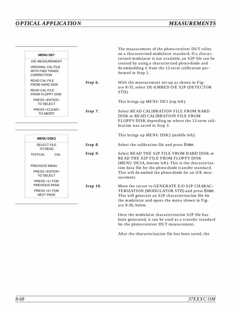
The measurement of the photo-receiver DUT relieson a characterized modulator standard. If a charac-terized modulator is not available, an S2P file can becreated by using a characterized photo-diode andde-embedding it from the 12-term calibration per-formed in Step 2.
Step 6. With the measurement set-up as shown in Fig-ure 8-35, select DE-EMBED O/E S2P (DETECTORSTD).
This brings up MENU DE5 (top left).
Step 7. Select READ CALIBRATION FILE FROM HARDDISK or READ CALIBRATION FILE FROMFLOPPY DISK depending on where the 12-term cali-bration was saved in Step 3.
This brings up MENU DSK2 (middle left).
Step 8. Select the calibration file and press Enter.
Step 9. Select READ THE S2P FILE FROM HARD DISK orREAD THE S2P FILE FROM FLOPPY DISK(MENU DE5A, bottom left). This is the characteriza-tion data file for the photo-diode transfer standard.This will de-embed the photo-diode for an O/E mea-surement.
Step 10. Move the cursor to GENERATE E/O S2P CHARAC-TERIZATION (MODULATOR STD) and press Enter.This will generate an S2P characterization file forthe modulator and opens the menu shown in Fig-ure 8-36, below.
Once the modulator characterization S2P file hasbeen generated, it can be used as a transfer standardfor the photo-receiver DUT measurement.
After the characterization file has been saved, the
OPTICAL APPLICATION MEASUREMENTS
8-68 37XXXC OM
MENU DE7
O/E MEASUREMENT
ORIGINAL CAL FILEWITH FWD TRANSCORRECTION
READ CAL FILEFROM HARD DISK
READ CAL FILEFROM FLOPPY DISK
PRESS <ENTER>TO SELECT
PRESS <CLEAR>TO ABORT
MENU DSK2
SELECT FILETO READ
TESTCAL CAL
PREVIOUS MENU
PRESS <ENTER>TO SELECT
PRESS <1> FORPREVIOUS PAGE
PRESS <2> FORNEXT PAGE

VNA returns to the O/E measurement menu shownin Figure 8-38, below.
Step 11. Move the cursor to MEASURE O/E DUT (DETEC-TOR) and press Enter.
This brings up MENU DE7 (top left).
Step 12. Select READ CALIBRATION FILE FROM HARDDISK or READ CALIBRATION FILE FROMFLOPPY DISK depending on where the original12-term calibration was saved in Step 3.
This brings up MENU DSK2 (lower left).
37XXXC OM 8-69
MEASUREMENTS OPTICAL APPLICATION
Figure 8-38. O/E Measurement Menu

Step 13. Read the S2P file for the modulator that was gener-ated in Step 10 from the hard drive or floppy drive(MENU DE7A, bottom left). This will de-embed themodulator response from the set-up for an O/E mea-surement.
NOTEIf an S2P file is not available, it can be gen-erated from the characterization data pro-vided by the vendor. This is explained onpage 8-71.
An O/E measurement of a photo-receiver is shown below. The S21measurement represents the transfer function of the photo-receiverand S22 represents the electrical return loss.
OPTICAL APPLICATION MEASUREMENTS
8-70 37XXXC OM
Figure 8-39. O/E Measurement of a Photo-receiver
MENU DE7A
O/E MEASUREMENT
TRANSFER STANDARDTO BE DE-EMBEDDED(MODULATOR)
READ S2P FILEFROM HARD DISK
READ S2P FILEFROM FLOPPY DISK
PRESS <ENTER>TO SELECT
PRESS <CLEAR>TO ABORT
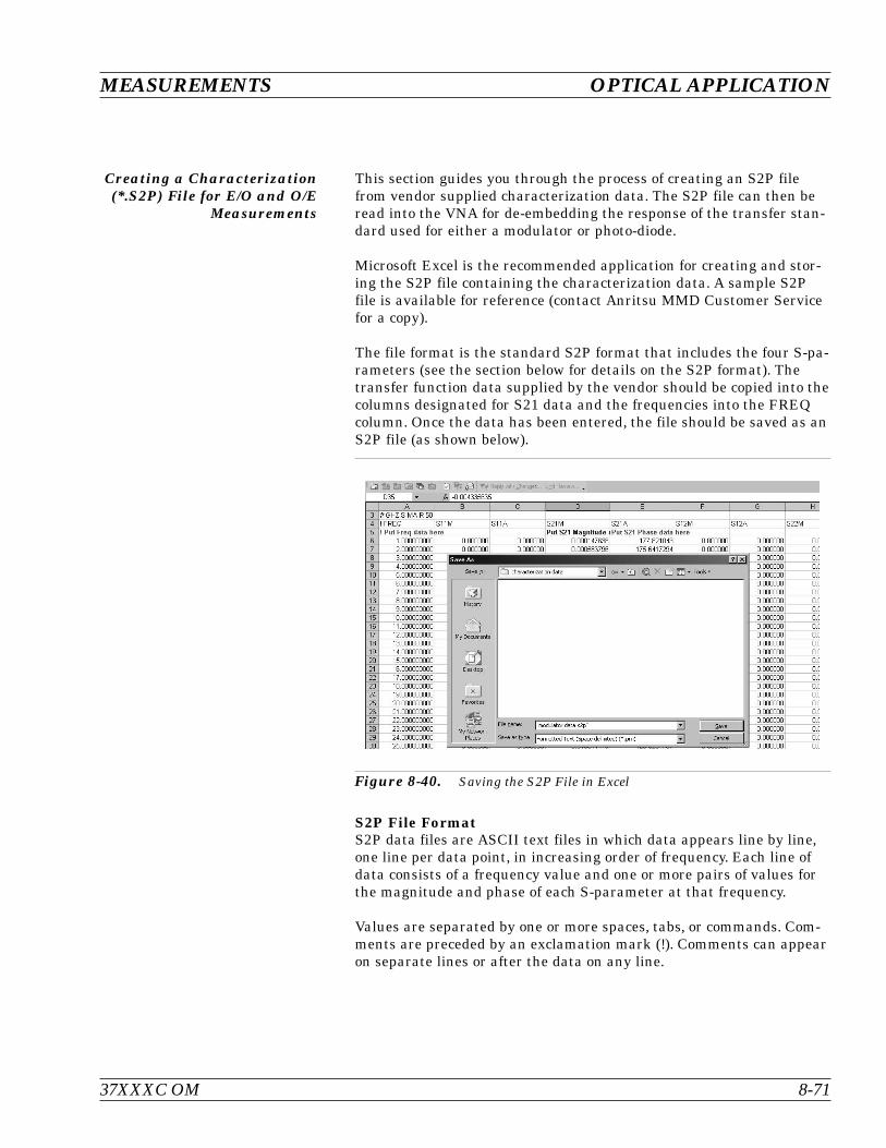
Creating a Characterization(*.S2P) File for E/O and O/E
Measurements
This section guides you through the process of creating an S2P filefrom vendor supplied characterization data. The S2P file can then beread into the VNA for de-embedding the response of the transfer stan-dard used for either a modulator or photo-diode.
Microsoft Excel is the recommended application for creating and stor-ing the S2P file containing the characterization data. A sample S2Pfile is available for reference (contact Anritsu MMD Customer Servicefor a copy).
The file format is the standard S2P format that includes the four S-pa-rameters (see the section below for details on the S2P format). Thetransfer function data supplied by the vendor should be copied into thecolumns designated for S21 data and the frequencies into the FREQcolumn. Once the data has been entered, the file should be saved as anS2P file (as shown below).
S2P File FormatS2P data files are ASCII text files in which data appears line by line,one line per data point, in increasing order of frequency. Each line ofdata consists of a frequency value and one or more pairs of values forthe magnitude and phase of each S-parameter at that frequency.
Values are separated by one or more spaces, tabs, or commands. Com-ments are preceded by an exclamation mark (!). Comments can appearon separate lines or after the data on any line.
37XXXC OM 8-71
MEASUREMENTS OPTICAL APPLICATION
Figure 8-40. Saving the S2P File in Excel

The standard S2P file format consists of:
Option Lines
Data Lines
Comments
The option line contains the specifications of the data, for example, thefrequency units, the normalizing impedance, and the measured param-eter (S, Y, Z, etc.)
The option line format is:
# <frequency unit> <parameter> <format> <Rn>
where:
# The delimiter that tells the program you are specifying these param-eters
frequency unit The set of units desired (GHz, MHz, KHz, Hz)
parameter The parameter desired (S, Y or Z for S1P components; S, Y, Z, G, orH for S2P components; S for S3P or S4P components)
format The format desired (DB for dB-angle, MA for magnitude-angle, or RIfor real-imaginary)
R n The reference resistance in ohms, where n is a positive number ofohms (the real impedance to which the parameters are normalized)
The default option line for a component data files is:
# GHZ S MA R 50
For Y-parameters with real imaginary data, the option line header willchange to:
# GHz Y RI R 50
The data lines contain the data of interest. Data for all four S-parame-ters will be listed on a single line for a particular frequency point. Theformat is:
Frequency S11 S21 S12 S22
Data Line Examples:Frequency S11 (magnitude) S11 (angle)0.040000000 1.426492E-04 18.6420.139900000 2.840961E-03 22.262
OPTICAL APPLICATION MEASUREMENTS
8-72 37XXXC OM
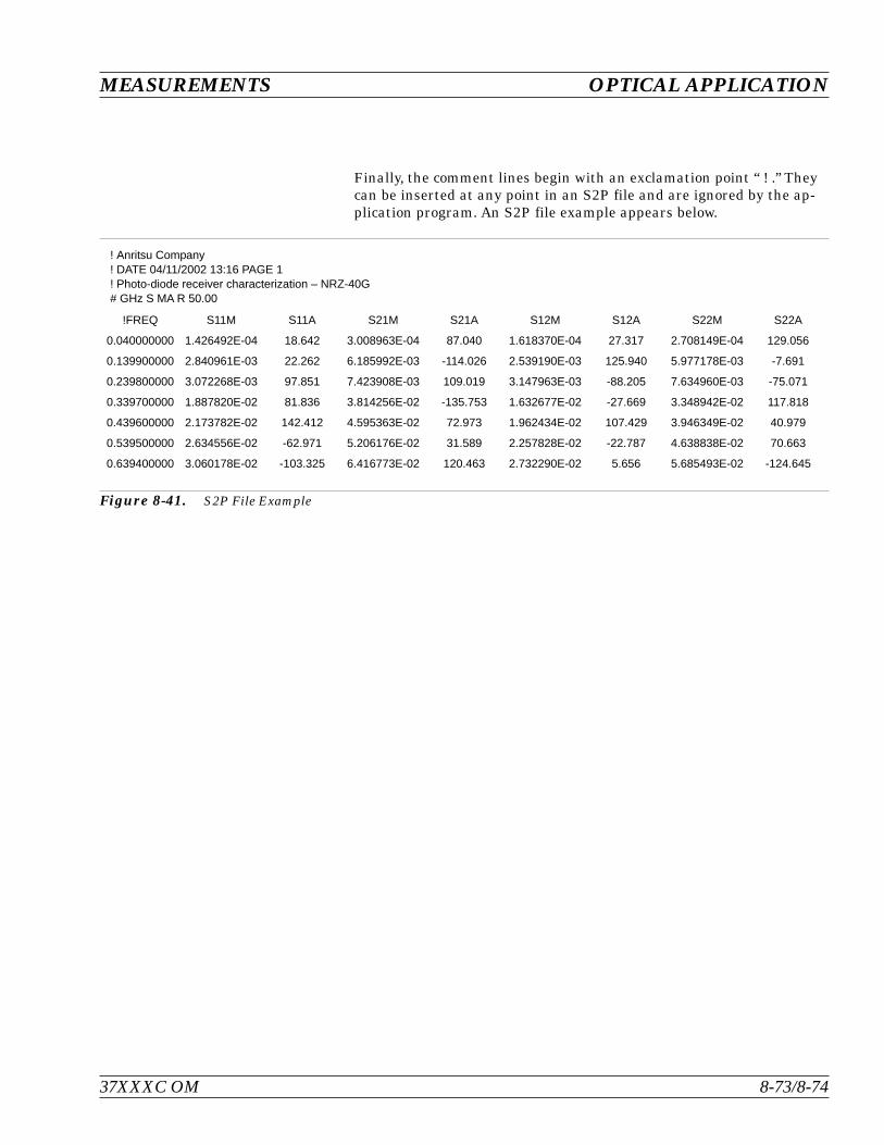
Finally, the comment lines begin with an exclamation point “ ! .” Theycan be inserted at any point in an S2P file and are ignored by the ap-plication program. An S2P file example appears below.
37XXXC OM 8-73/8-74
MEASUREMENTS OPTICAL APPLICATION
! Anritsu Company! DATE 04/11/2002 13:16 PAGE 1! Photo-diode receiver characterization – NRZ-40G# GHz S MA R 50.00
!FREQ S11M S11A S21M S21A S12M S12A S22M S22A
0.040000000 1.426492E-04 18.642 3.008963E-04 87.040 1.618370E-04 27.317 2.708149E-04 129.056
0.139900000 2.840961E-03 22.262 6.185992E-03 -114.026 2.539190E-03 125.940 5.977178E-03 -7.691
0.239800000 3.072268E-03 97.851 7.423908E-03 109.019 3.147963E-03 -88.205 7.634960E-03 -75.071
0.339700000 1.887820E-02 81.836 3.814256E-02 -135.753 1.632677E-02 -27.669 3.348942E-02 117.818
0.439600000 2.173782E-02 142.412 4.595363E-02 72.973 1.962434E-02 107.429 3.946349E-02 40.979
0.539500000 2.634556E-02 -62.971 5.206176E-02 31.589 2.257828E-02 -22.787 4.638838E-02 70.663
0.639400000 3.060178E-02 -103.325 6.416773E-02 120.463 2.732290E-02 5.656 5.685493E-02 -124.645
Figure 8-41. S2P File Example

Table of Contents
9-1 INTRODUCTION . . . . . . . . . . . . . . . . . . . . . . . . . . . . . . . . . . . 9-3
9-2 TIME DOMAIN MEASUREMENTS . . . . . . . . . . . . . . . . . . . . . . . . . 9-3
9-3 OPERATING TIME DOMAIN . . . . . . . . . . . . . . . . . . . . . . . . . . . . 9-8
9-4 WINDOWING. . . . . . . . . . . . . . . . . . . . . . . . . . . . . . . . . . . . . 9-11
9-5 GATING. . . . . . . . . . . . . . . . . . . . . . . . . . . . . . . . . . . . . . . . 9-12
9-6 ANTI-GATING . . . . . . . . . . . . . . . . . . . . . . . . . . . . . . . . . . . . 9-14
9-7 EXAMPLES, GATING AND ANTI-GATING . . . . . . . . . . . . . . . . . . . . 9-14
9-8 TIME DOMAIN MENUS. . . . . . . . . . . . . . . . . . . . . . . . . . . . . . . 9-14
Chapter 9Time Domain


Chapter 9Time Domain
9-1 INTRODUCTION This chapter describes the optional Time Domain feature.
9-2 TIME DOMAINMEASUREMENTS
The Option 2, Time Domain feature provides a useful measurementtool for determining the location of impedance discontinuities. Sometypical applications are identifying and analyzing circuit elements, iso-lating and analyzing a desired response, locating faults in cables, andmeasuring antennas.
The relationship between the frequency-domain response and thetime-domain response of a network is described mathematically by theFourier transform.
The 37XXXC makes measurements in the frequency domain then cal-culates the inverse Fourier transform to give the time-domain re-sponse. The time-domain response is displayed as a function of time(or distance). This computational technique benefits from the wide dy-namic range and the error correction of the frequency-domain data.
Let us examine the time-domain capabilities. Two measurementmodes are available: lowpass and bandpass.
We use the lowpass mode with devices that have a dc or low-frequencyresponse. In the lowpass mode two responses to the device-under-test(DUT) are available: impulse or step response.
The frequencies used for the test must be harmonically related (inte-ger multiples) to the start frequency. The simplest way to calculatethis relationship is to divide the highest frequency in the calibrationby 1600 (the default number-of-points available); this is the start fre-quency. For example, if the highest frequency is 40 GHz, the calculatedstart frequency is 0.025 GHz (40/1600). If the highest frequency is 65GHz, the calculated start frequency is 0.040625 GHz (65/1600).
37XXXC OM 9-3
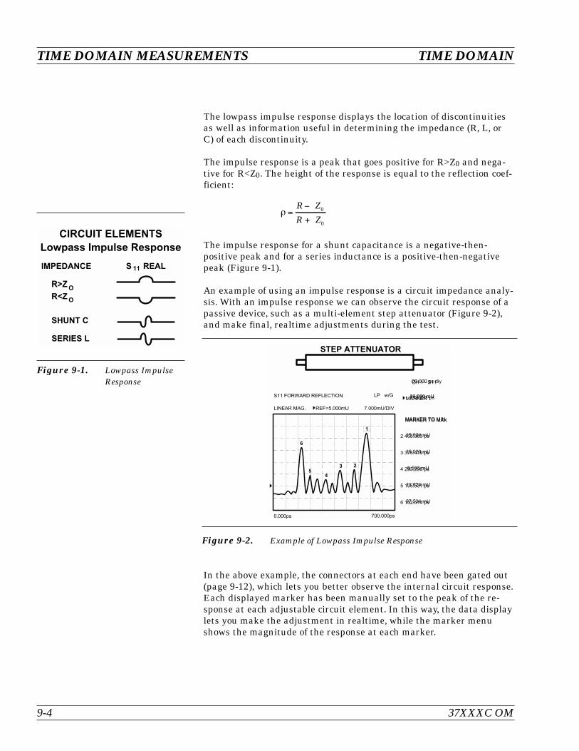
The lowpass impulse response displays the location of discontinuitiesas well as information useful in determining the impedance (R, L, orC) of each discontinuity.
The impulse response is a peak that goes positive for R>Z0 and nega-tive for R<Z0. The height of the response is equal to the reflection coef-ficient:
R ZR Z
0
0
The impulse response for a shunt capacitance is a negative-then-positive peak and for a series inductance is a positive-then-negativepeak (Figure 9-1).
An example of using an impulse response is a circuit impedance analy-sis. With an impulse response we can observe the circuit response of apassive device, such as a multi-element step attenuator (Figure 9-2),and make final, realtime adjustments during the test.
In the above example, the connectors at each end have been gated out(page 9-12), which lets you better observe the internal circuit response.Each displayed marker has been manually set to the peak of the re-sponse at each adjustable circuit element. In this way, the data displaylets you make the adjustment in realtime, while the marker menushows the magnitude of the response at each marker.
TIME DOMAIN MEASUREMENTS TIME DOMAIN
9-4 37XXXC OM
6 1
4 1
; < 8 9 9 + < = 9 9 < 9
Figure 9-1. Lowpass ImpulseResponse
7 . 7 7 7 J - 7 7 . 7 7 7 J
% #
' . O 4 . 7 7 7 < - . 7 7 7 < $ # &
! Z $ '
6 4 . 4 > J - . 4 : > <
> 6 4 . : 6 : J 4 . 6 > <
: : - 4 . > G J 4 . 7 7 <
> G : . G 6 J G . 4 G : <
4 G 4 . 4 : J . 6 > <
4 . G J : 6 . B G 7 <
" 8 7 7 . 7 7 7 J 1
#
.
"&
Figure 9-2. Example of Lowpass Impulse Response

The lowpass step response displays the location of discontinuities aswell as information useful in determining the impedance (R, L, or C) ofeach discontinuity. If you are familiar with time-domain reflectometry(TDR) you may feel more comfortable with step response, as the dis-plays are similar.
The lowpass step response for a resistive impedance is a positive levelshift for R>Z0 and a negative level shift for R<Z0. The height of the re-sponse is equal to the reflection coefficient
R ZR Z
0
0
The step response for a shunt capacitance is a negative peak, and for aseries inductance it is a positive peak (Figure 9-3).
An example of using the lowpass step response is cable-fault location.In the frequency domain a cable with a fault exhibits a much worse
match than a good cable. Using lowpass step response, both the loca-tion of the discontinuity and the information about its type are avail-able (Figure 9-4).
In the above example, the dip in the display shows the shunt-capacitive response caused by a crimp in the cable. The response at theend of the cable shows the step-up that is typical of an open (Figure9-3, left).
The 37XXXC bandpass mode gives the response of the DUT to anRF-burst stimulus. Two types of response are available: impulse andphasor-impulse. An advantage of the bandpass mode is that any fre-quency range can be used. Use this mode with devices that do not havea dc or low-frequency path.
37XXXC OM 9-5
TIME DOMAIN TIME DOMAIN MEASUREMENTS
6 1
4 1
; < 8 9 9 < 9 < 9
Figure 9-3. Lowpass StepResponse
> 7 . 7 7 7 <7 . 7 7 7 < <
:
)
Figure 9-4. Example of Lowpass Step Response
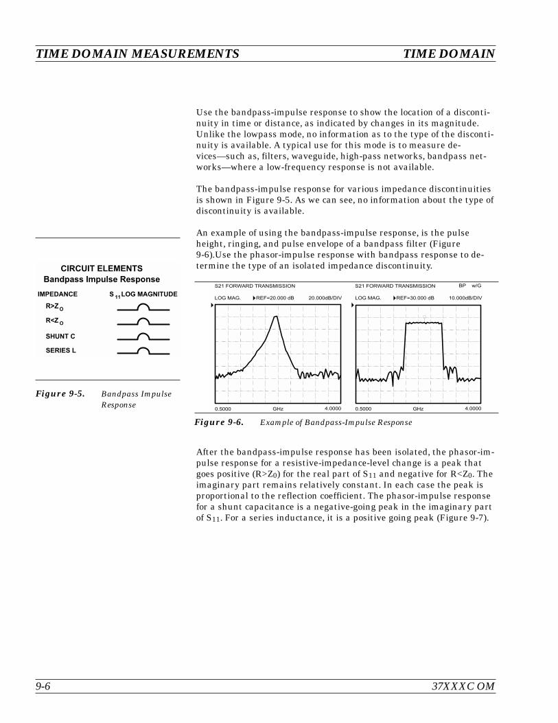
Use the bandpass-impulse response to show the location of a disconti-nuity in time or distance, as indicated by changes in its magnitude.Unlike the lowpass mode, no information as to the type of the disconti-nuity is available. A typical use for this mode is to measure de-vices—such as, filters, waveguide, high-pass networks, bandpass net-works—where a low-frequency response is not available.
The bandpass-impulse response for various impedance discontinuitiesis shown in Figure 9-5. As we can see, no information about the type ofdiscontinuity is available.
An example of using the bandpass-impulse response, is the pulseheight, ringing, and pulse envelope of a bandpass filter (Figure9-6).Use the phasor-impulse response with bandpass response to de-termine the type of an isolated impedance discontinuity.
After the bandpass-impulse response has been isolated, the phasor-im-pulse response for a resistive-impedance-level change is a peak thatgoes positive (R>Z0) for the real part of S11 and negative for R<Z0. Theimaginary part remains relatively constant. In each case the peak isproportional to the reflection coefficient. The phasor-impulse responsefor a shunt capacitance is a negative-going peak in the imaginary partof S11. For a series inductance, it is a positive going peak (Figure 9-7).
TIME DOMAIN MEASUREMENTS TIME DOMAIN
9-6 37XXXC OM
6 1
) 8 * < 8 9 9 + < = 9 9 < 9
4 1
Figure 9-5. Bandpass ImpulseResponse
' ' .
7 . 4 7 7 7 ' " ; > . 7 7 7 7
O 7 . 7 7 7 / 7 . 7 7 7 / $ # & ' ' .
7 . 4 7 7 7 ' " ; > . 7 7 7 7
7 . 7 7 7 / $ # & O : 7 . 7 7 7 /
/ ! Z $ ' % # % #
Figure 9-6. Example of Bandpass-Impulse Response

Next, let us look at a complex circuit. A resistive impedance changeR<Z0 and a shunt capacitance and series inductance. These impedancechanges are shown in the time domain for the lowpass-impulse re-sponse, lowpass-step response, and bandpass-impulse response (Figure9-8).
The 37XXXC processes bandpass-impulse-response data to obtainphasor-impulse response. This becomes most advantageous where botha reactive reflection and an impedance change occur at the same loca-tion. The real part of the time-domain response shows the location ofimpedance level changes, while the imaginary part shows the type ofreactive discontinuity. Phasor-impulse response displays one disconti-nuity at a time (Figure 9-9).
37XXXC OM 9-7
TIME DOMAIN TIME DOMAIN MEASUREMENTS
& > + ' > + ' > +
& ' " ' & '
% ! !
% ! !
/ # ! !
Figure 9-7. Complex Impedances
) 8 * < 8 9 9 ? 8 9 @ + < = 9 9 < 9
6 1
4 1
Figure 9-8. Bandpass PhasorResponse
)
& > + ' > +
" ' & '
Figure 9-9. Phasor-Impulse Response Data
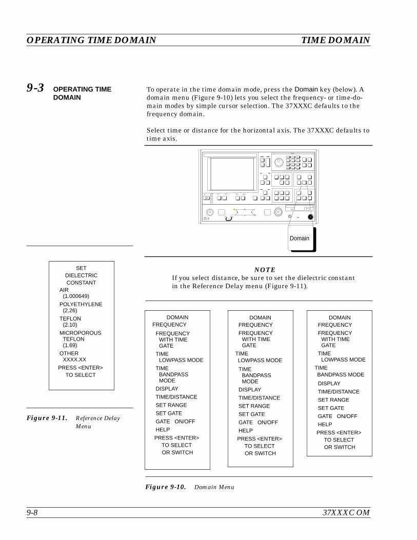
9-3 OPERATING TIMEDOMAIN
To operate in the time domain mode, press the Domain key (below). Adomain menu (Figure 9-10) lets you select the frequency- or time-do-main modes by simple cursor selection. The 37XXXC defaults to thefrequency domain.
Select time or distance for the horizontal axis. The 37XXXC defaults totime axis.
NOTEIf you select distance, be sure to set the dielectric constantin the Reference Delay menu (Figure 9-11).
OPERATING TIME DOMAIN TIME DOMAIN
9-8 37XXXC OM
Figure 9-10. Domain Menu
DOMAINFREQUENCY
FREQUENCYWITH TIMEGATE
TIMELOWPASS MODE
TIMEBANDPASSMODE
DISPLAY
TIME/DISTANCE
SET RANGE
SET GATE
GATE ON/OFF
HELP
PRESS <ENTER>TO SELECTOR SWITCH
DOMAINFREQUENCY
FREQUENCYWITH TIMEGATE
TIMELOWPASS MODE
TIMEBANDPASSMODE
DISPLAY
TIME/DISTANCE
SET RANGE
SET GATE
GATE ON/OFF
HELP
PRESS <ENTER>TO SELECTOR SWITCH
DOMAINFREQUENCY
FREQUENCYWITH TIMEGATE
TIMELOWPASS MODE
TIMEBANDPASS MODE
DISPLAY
TIME/DISTANCE
SET RANGE
SET GATE
GATE ON/OFF
HELP
PRESS <ENTER>TO SELECTOR SWITCH
Figure 9-11. Reference DelayMenu
SETDIELECTRICCONSTANT
AIR(1.000649)
POLYETHYLENE(2.26)
TEFLON(2.10)
MICROPOROUSTEFLON(1.69)
OTHERXXXX.XX
PRESS <ENTER>TO SELECT
Domain

Select SET RANGE and use the START/STOP or GATE/SPAN selec-tions to set the range (Figure 9-12).
For the lowpass mode select either IMPULSE or STEP Response andset the DC term. The 37XXXCdefaults to the IMPULSE Response andthe AUTO EXTRAPOLATE mode for the DC term (Figure 9-13).
NOTEThe bandpass mode displays Bandpass Impulse Responseunless we select Phasor Impulse Response.
37XXXC OM 9-9
TIME DOMAIN OPERATING TIME DOMAIN
Figure 9-12. Set Range Menu
LOWPASS TIMEDOMAIN SETUP
STARTXXX.XXX ps
STOPXXX.XXX ps
CENTERXXX.XXX ps
SPANXXX.XXX ps
MARKER RANGE
RESPONSEIMPULSE/STEP
MORE
PRESS <ENTER>TO SELECT
DOMAINFREQUENCY
FREQUENCYWITH TIMEGATE
TIMELOWPASSMODE
TIMEBANDPASSMODE
DISPLAY
TIME/DISTANCE
SET RANGE
SET GATE
GATE ON/OFF
HELP
PRESS <ENTER>TO SELECTOR SWITCH
BANDPASS TIMEDOMAIN SETUPSTARTXXX.XXX ps
STOPXXX.XXX ps
CENTERXXX.XXX ps
SPANXXX.XXX ps
MARKER RANGE
PHASOR ON/OFF
IMPULSE
HELP - PHASORIMPULSE
MORE

The Marker Range menu allows us to zoom in and display the rangebetween two selected markers (Figure 9-14).
OPERATING TIME DOMAIN TIME DOMAIN
9-10 37XXXC OM
Figure 9-13. Response Menus
SET D.C. TERMFOR LOWPASSPROCESSING
AUTOEXTRAPOLATE
LINEIMPEDANCE
OPEN
SHORT
OTHER–XXX.XXX #ABOVE VALUEREPRESENTS A
REFLECTIONCOEFF. OFXX.XXX mU
PREVIOUS MENU
PRESS <ENTER>TO SELECT
LOWPASS TIMEDOMAIN SETUPSTART
XXX.XXX ps
STOPXXX.XXX ps
CENTERXXX.XXX ps
SPANXXX.XXX ps
MARKER RANGE
RESPONSEIMPULSE/STEP
MORE
PRESS <ENTER>TO SELECT
BANDPASS TIMEDOMAIN SETUPSTART
XXX.XXX ps
STOPXXX.XXX ps
CENTERXXX.XXX ps
SPANXXX.XXX ps
MARKER RANGE
PHASOR ON/OFFIMPULSE
HELP-PHASORIMPULSE
MORE
PRESS <ENTER>TO SELECT
Figure 9-14. Marker Range Menus
TIMEMARKER SWEEPSTART TIME
MARKER ( )XXX.XXX nS
STOP TIMEMARKER ( )XXX.XXX nS
RESTOREORIGINALRANGE
PREVIOUS MENU
USE KEYPADTO CHOOSE
MARKER (1 - 6)OR
PRESS <ENTER>TO SELECT
LOWPASS TIMEDOMAIN SETUPSTART
XXX.XXX ps
STOPXXX.XXX ps
CENTERXXX.XXX ps
SPANXXX.XXX ps
MARKER RANGE
RESPONSEIMPULSE/STEP
MORE
PRESS <ENTER>TO SELECT

9-4 WINDOWING Windowing is a frequency filter that we apply to the frequency-domaindata when we convert it to time-domain data. This filtering rolls offthe abrupt transition at F1 and F2. This effectively produces a time-domain response with lower sidelobes. Windowing allows a limited de-gree of control over the pulse shape, trading off ringing (sidelobes) forpulse width (Figure 9-15).
We select windowing from the Time Domain Setup menu. Four differ-ent windows are available: RECTANGLE, NOMINAL, LOWSIDELOBE, and MINIMUM SIDELOBE. The RECTANGLE optionprovides the narrowest pulse width, while the MINIMUM SIDELOBEoption provides the least ringing (fewest sidelobes). The 37XXXC de-faults to the NOMINAL option, which is acceptable for most measure-ments. Windowing menus are shown in Figure 9-16.
37XXXC OM 9-11
TIME DOMAIN WINDOWING
% 5
"
C % 1 1 0 1 0
Figure 9-15. Windowing
Figure 9-16. Window Shape Menus
LOWPASS TIMEDOMAIN SETUPSET WINDOWNOMINAL
SET GATE
SET D.C. TERMXXX.XXX
PREVIOUS MENU
PRESS <ENTER>TO SELECT
LOWPASS TIMEDOMAIN SETUP
STARTXXX.XXX ps
STOPXXX.XXX ps
CENTERXXX.XXX ps
SPANXXX.XXX ps
MARKER RANGE
RESPONSEIMPULSE/STEP
MORE
PRESS <ENTER>TO SELECT
SHAPERECTANGULAR
NOMINAL
LOW SIDELOBE
MIN SIDELOBE
HELP
PRESS <ENTER>TO SELECT
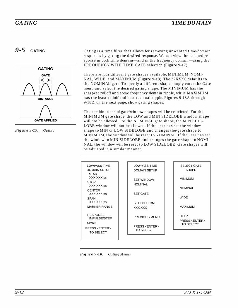
9-5 GATING Gating is a time filter that allows for removing unwanted time-domainresponses by gating the desired response. We can view the isolated re-sponse in both time domain—and in the frequency domain—using theFREQUENCY WITH TIME GATE selection (Figure 9-17).
There are four different gate shapes available: MINIMUM, NOMI-NAL, WIDE, and MAXIMUM (Figure 9-18). The 37XXXC defaults tothe NOMINAL gate. To specify a different shape simply enter the Gatemenu and select the desired gating shape. The MINIMUM has thesharpest rolloff and some frequency domain ripple, while MAXIMUMhas the least rolloff and best residual ripple. Figures 9-18A through9-18D, on the next page, show gating shapes.
The combinations of gate/window shapes will be restricted. For theMINIMUM gate shape, the LOW and MIN SIDELOBE window shapewill not be allowed. For the NOMINAL gate shape, the MIN SIDE-LOBE window will not be allowed. If the user has set the windowshape to MIN or LOW SIDELOBE and changes the-gate shape toMINIMUM, the window will be reset to NOMINAL. If the user has setthe window to MIN SIDELOBE and changes the gate shape to NOMI-NAL, the window will be reset to LOW SIDELOBE. Gate shapes willbe adjusted in a similar manner.
GATING TIME DOMAIN
9-12 37XXXC OM
Figure 9-17. Gating
Figure 9-18. Gating Menus
LOWPASS TIME
DOMAIN SETUP
SET WINDOW
NOMINAL
SET GATE
SET DC TERM
XXX.XXX
PREVIOUS MENU
PRESS <ENTER>TO SELECT
LOWPASS TIMEDOMAIN SETUP
STARTXXX.XXX ps
STOPXXX.XXX ps
CENTERXXX.XXX ps
SPANXXX.XXX ps
MARKER RANGE
RESPONSEIMPULSE/STEP
MORE
PRESS <ENTER>TO SELECT
SELECT GATESHAPE
MINIMUM
NOMINAL
WIDE
MAXIMUM
HELP
PRESS <ENTER>TO SELECT

37XXXC OM 9-13
TIME DOMAIN GATING
An informational message will be displayed in the data area when thewindow or gate shape reset in this way. The message will last twosweeps and will say:
“GATE SHAPE ADJUSTED” or “WINDOW SHAPE ADJUSTED”depending on which was changed by the software.
Figure 9-18A. Minimum Gate Shape Figure 9-18B. Nominal Gate Shape
Figure 9-18C. Wide Gate Shape Figure 9-18D. Maximum Gate Shape

9-6 ANTI-GATING Anti-gating is the opposite of gating. Whereby, gating provides for re-moving all but the desired response, anti-gating displays all but thedesired response. To provide anti-gating, gate in the normal manner,except use a minus value for the SPAN width.
9-7 EXAMPLES, GATINGAND ANTI-GATING
Examples of anti-gating are shown in Figures 9-19 through 9-24. Thefigures, all captured from an actual VNA display, show a sequence ofmeasurements using gating and anti-gating to enhance measurementtechnique and accuracy. The examples use a dented length of semi-rigid cable having a connector on one end and a connector-DUT on theother end, as shown below. The DUT has a smoothly varying 15 dB re-turn loss.
9-8 TIME DOMAIN MENUS A flow diagram of the menus associated with the Time Domain Optionis shown in foldout Figure 9-25. The menu choices are described in Ap-pendix A. They appear in alphabetical order by their call letters: TD1,TD2, TD2dl, etc.
ANTI-GATING TIME DOMAIN
9-14 37XXXC OM
Connector
Dent
15 dBDUT
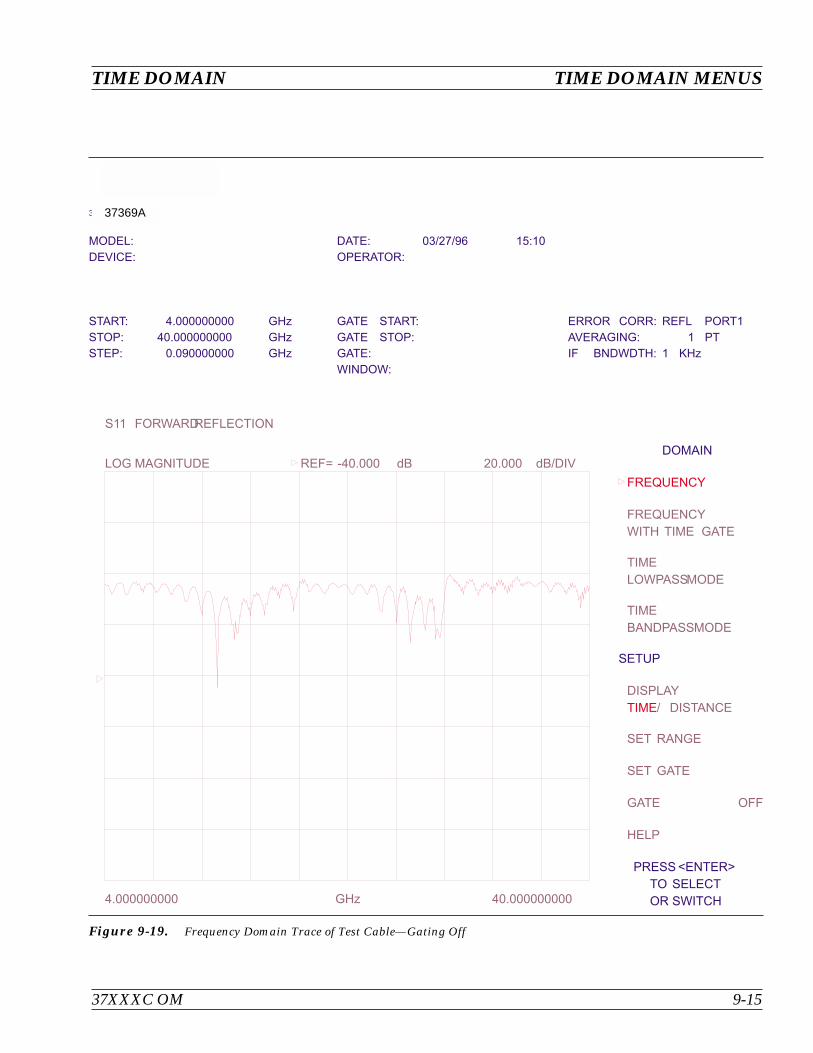
37XXXC OM 9-15
TIME DOMAIN TIME DOMAIN MENUS
37369A
MODEL: DATE: 03/27/96 15:10
DEVICE: OPERATOR:
START: 4.000000000 GHz GATE START: ERROR CORR: REFL PORT1
STOP: 40.000000000 GHz GATE STOP: AVERAGING: 1 PT
STEP: 0.090000000 GHz GATE: IF BNDWDTH: 1 KHz
WINDOW:
FREQUENCY
TIME
FREQUENCY
WITH TIME GATE
TIME
LOWPASSMODE
TIME
BANDPASSMODE
DISPLAY
/ DISTANCE
SET RANGE
SET GATE
GATE OFF
HELP
GHz4.000000000 40.000000000
S11 FORWARDREFLECTION
LOG MAGNITUDE REF= -40.000 dB 20.000 dB/DIVDOMAIN
SETUP
PRESS <ENTER>
TO SELECT
OR SWITCH
Figure 9-19. Frequency Domain Trace of Test Cable—Gating Off
37369A
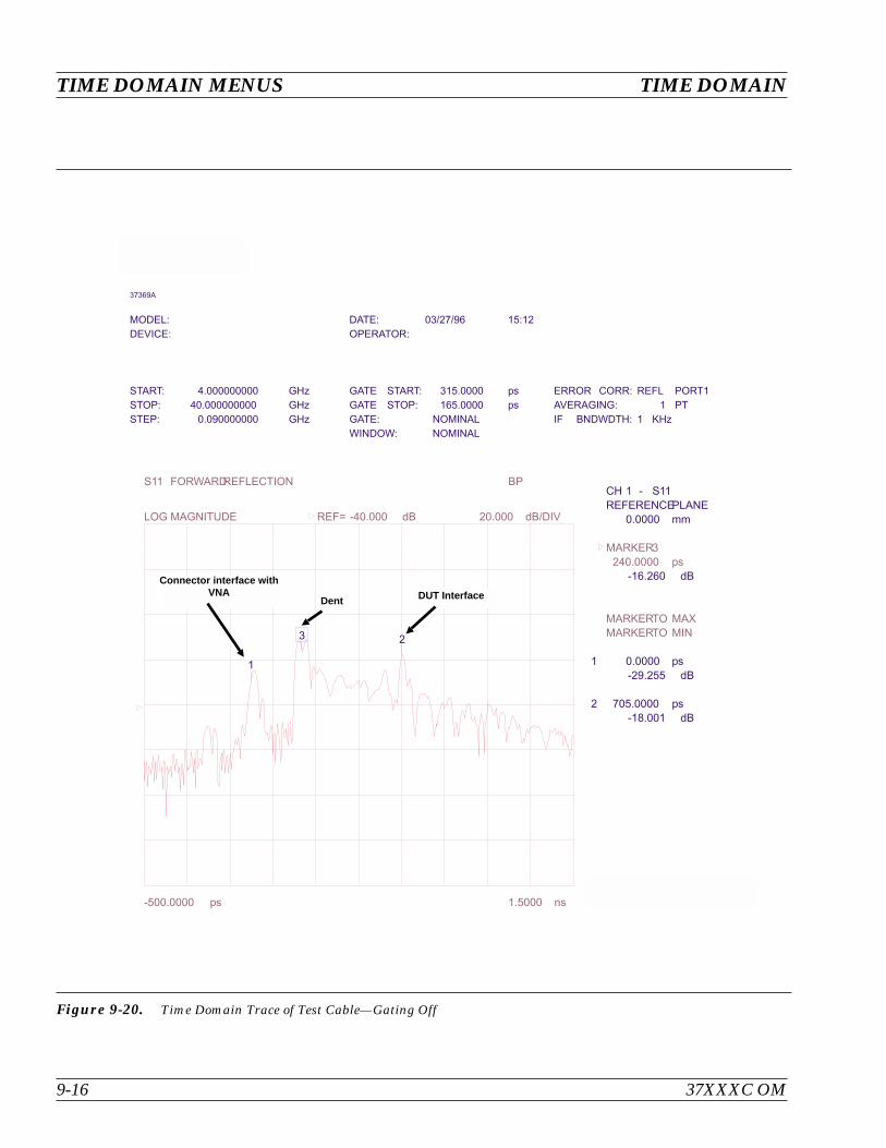
TIME DOMAIN MENUS TIME DOMAIN
9-16 37XXXC OM
37369A
MODEL: DATE: 03/27/96 15:12
DEVICE: OPERATOR:
START: 4.000000000 GHz GATE START: 315.0000 ps ERROR CORR: REFL PORT1
STOP: 40.000000000 GHz GATE STOP: 165.0000 ps AVERAGING: 1 PT
STEP: 0.090000000 GHz GATE: NOMINAL IF BNDWDTH: 1 KHz
WINDOW: NOMINAL
MARKER3
240.0000 ps
MARKERTO MAX
MARKERTO MIN
MARKERREADOUT
FUNCTIONS-500.0000 ps 1.5000 ns
BPS11 FORWARDREFLECTION
LOG MAGNITUDE REF= -40.000 dB 20.000 dB/DIV
CH 1 - S11
REFERENCEPLANE
0.0000 mm
0.0000 ps
705.0000 ps
-16.260 dB
-29.255 dB
-18.001 dB
1
2
1
23
Figure 9-20. Time Domain Trace of Test Cable—Gating Off
Connector interface withVNA
Dent DUT Interface
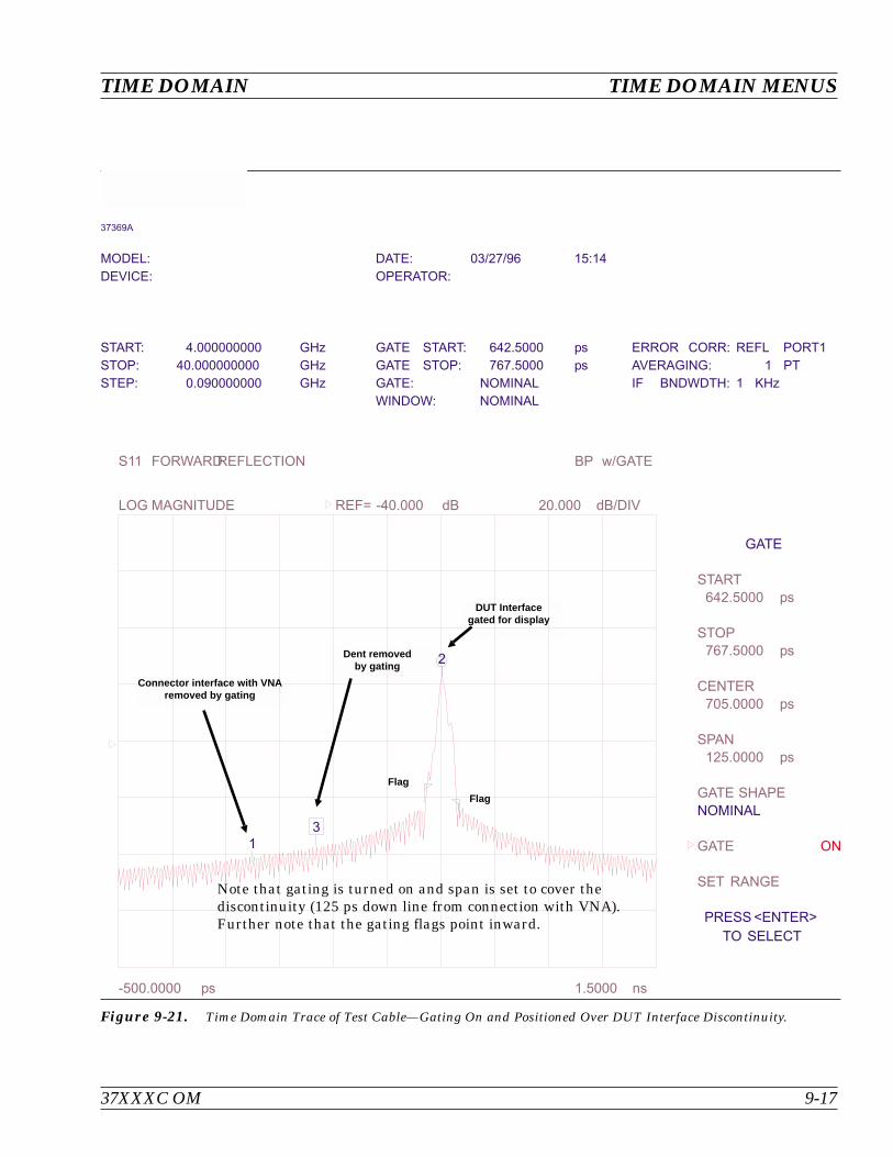
37XXXC OM 9-17
TIME DOMAIN TIME DOMAIN MENUS
37369A
MODEL: DATE: 03/27/96 15:14
DEVICE: OPERATOR:
START: 4.000000000 GHz GATE START: 642.5000 ps ERROR CORR: REFL PORT1
STOP: 40.000000000 GHz GATE STOP: 767.5000 ps AVERAGING: 1 PT
STEP: 0.090000000 GHz GATE: NOMINAL IF BNDWDTH: 1 KHz
WINDOW: NOMINAL
ON
START
642.5000 ps
STOP
767.5000 ps
CENTER
705.0000 ps
SPAN
125.0000 ps
GATE SHAPE
GATE
SET RANGE
-500.0000 ps 1.5000 ns
BP w/GATES11 FORWARDREFLECTION
LOG MAGNITUDE REF= -40.000 dB 20.000 dB/DIV
GATE
NOMINAL
PRESS <ENTER>
TO SELECT
1
2
3
Figure 9-21. Time Domain Trace of Test Cable—Gating On and Positioned Over DUT Interface Discontinuity.
Connector interface with VNAremoved by gating
DUT Interfacegated for display
Dent removedby gating
Flag
Flag
Note that gating is turned on and span is set to cover thediscontinuity (125 ps down line from connection with VNA).Further note that the gating flags point inward.
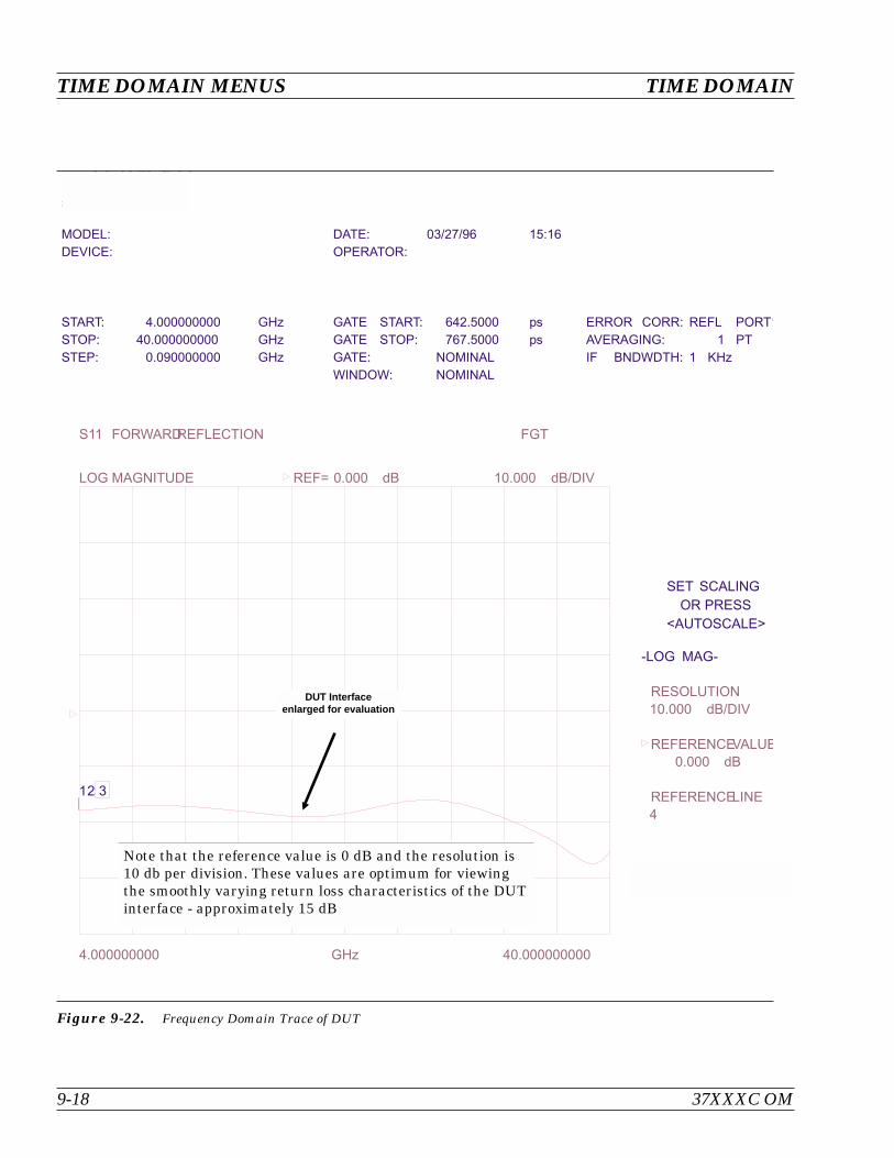
TIME DOMAIN MENUS TIME DOMAIN
9-18 37XXXC OM
37369A
MODEL: DATE: 03/27/96 15:16
DEVICE: OPERATOR:
START: 4.000000000 GHz GATE START: 642.5000 ps ERROR CORR: REFL PORT1
STOP: 40.000000000 GHz GATE STOP: 767.5000 ps AVERAGING: 1 PT
STEP: 0.090000000 GHz GATE: NOMINAL IF BNDWDTH: 1 KHz
WINDOW: NOMINAL
RESOLUTION
10.000 dB/DIV
REFERENCEVALUE
0.000 dB
REFERENCELINE
4
GHz4.000000000 40.000000000
FGTS11 FORWARDREFLECTION
LOG MAGNITUDE REF= 0.000 dB 10.000 dB/DIV
SET SCALING
OR PRESS
<AUTOSCALE>
-LOG MAG-
12 3
Figure 9-22. Frequency Domain Trace of DUT
DUT Interfaceenlarged for evaluation
Note that the reference value is 0 dB and the resolution is10 db per division. These values are optimum for viewingthe smoothly varying return loss characteristics of the DUTinterface - approximately 15 dB

37XXXC OM 9-19
TIME DOMAIN TIME DOMAIN MENUS
37369A
MODEL: DATE: 03/27/96 15:19
DEVICE: OPERATOR:
START: 4.000000000 GHz GATE START: 315.0000 ps ERROR CORR: REFL PORT1
STOP: 40.000000000 GHz GATE STOP: 165.0000 ps AVERAGING: 1 PT
STEP: 0.090000000 GHz GATE: NOMINAL IF BNDWDTH: 1 KHz
WINDOW: NOMINAL
O
START
315.0000 ps
STOP
165.0000 ps
CENTER
240.0000 ps
SPAN
-150.0000 ps
GATE SHAPE
GATE
SET RANGE
-500.0000 ps 1.5000 ns
BP w/GATES11 FORWARDREFLECTION
LOG MAGNITUDE REF= -87.348 dB 20.000 dB/DIV
GATE
NOMINAL
PRESS <ENTER>
TO SELECT
1
2
3
Figure 9-23. Time Domain Trace of Test Cable—Gating On and Positioned Over Dent (Cable Fault)Interface Discontinuity.
FlagFlag
Dent removedby anti-gating
Note that anti-gating is turned on by changing the polarity ofthe SPAN to negative and changing its value to cover the dent.Also, note that the flags point outward.
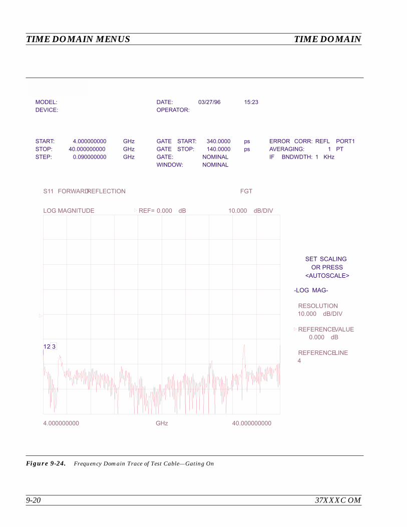
TIME DOMAIN MENUS TIME DOMAIN
9-20 37XXXC OM
37369A
MODEL: DATE: 03/27/96 15:23
DEVICE: OPERATOR:
START: 4.000000000 GHz GATE START: 340.0000 ps ERROR CORR: REFL PORT1
STOP: 40.000000000 GHz GATE STOP: 140.0000 ps AVERAGING: 1 PT
STEP: 0.090000000 GHz GATE: NOMINAL IF BNDWDTH: 1 KHz
WINDOW: NOMINAL
RESOLUTION
10.000 dB/DIV
REFERENCEVALUE
0.000 dB
REFERENCELINE
4
GHz4.000000000 40.000000000
FGTS11 FORWARDREFLECTION
LOG MAGNITUDE REF= 0.000 dB 10.000 dB/DIV
SET SCALING
OR PRESS
<AUTOSCALE>
-LOG MAG-
12 3
Figure 9-24. Frequency Domain Trace of Test Cable—Gating On
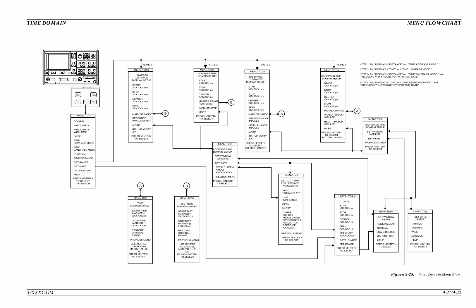
37XXXC OM 9-21/9-22
TIME DOMAIN MENU FLOWCHART
Figure 9-25. Time Domain Menu Flow


Table of Contents
10-1 INTRODUCTION. . . . . . . . . . . . . . . . . . . . . . . . . . . . . . . . . . . 10-3
10-2 DESCRIPTION . . . . . . . . . . . . . . . . . . . . . . . . . . . . . . . . . . . . 10-3
10-3 CALIBRATIONS . . . . . . . . . . . . . . . . . . . . . . . . . . . . . . . . . . . 10-4
10-4 DEFINITION . . . . . . . . . . . . . . . . . . . . . . . . . . . . . . . . . . . . . 10-4
10-5 PHYSICAL SETUP. . . . . . . . . . . . . . . . . . . . . . . . . . . . . . . . . . 10-6
10-6 CHARACTERIZATION FILES . . . . . . . . . . . . . . . . . . . . . . . . . . . 10-7
10-7 USING AUTOCAL . . . . . . . . . . . . . . . . . . . . . . . . . . . . . . . . . . 10-9
10-8 PIN DEPTH SPECIFICATIONS . . . . . . . . . . . . . . . . . . . . . . . . . . 10-13
10-9 AUTOCAL MENUS FLOW DIAGRAM . . . . . . . . . . . . . . . . . . . . . . 10-14
Chapter 10AutoCal
IMPORTANT NOTEThe 37100C Direct Access Receiver cannot make S-parameter measurements without an ex-ternal reflectometer setup. This manual describes calibration and S-parameter measure-ments for 372XXC and 373XXC. Most of these measurements can also be used with the371XXC assuming the user understands the need for an external reflectometer.

AUTOCAL MODULE 36581KKF
40 MHz - 20 GHz
LEFT
RIGHT
Power
Operate
Figure 10-1. AutoCal Module, Power Supply, and Calibration Coefficients Disk
Power Supply
AutoCal
Calibration CoefficientsDisk

Chapter 10AutoCal
10-1 INTRODUCTION This chapter provides a general description of the AutoCal calibrators,including specifications, setup, and the use of the associated softwareand on-line documentation. This series has three models, as shown be-low. Throughout this manual, the term AutoCal will refer to the series.Individual models will be referred to by model number. Figure 10-1shows the AutoCal module and all of its attaching parts.
Model Switch Freq. Range Connector
36581NNF Electronic 40MHz-18 GHz N (Male)-N(Fem)
36581KKF Electronic 40MHz-20 GHz K(Male)-K(Fem)
36582KKF Mechanical 40MHz-40 GHz K(Male)-K(Fem)
10-2 DESCRIPTION The AutoCal module provides an automatic system for fast, repeatablehigh-quality calibrations of a Vector Network Analyzer (VNA). TheAutoCal module is connected between the VNA's test ports 1 and 2 toperform the calibration. Refer to Figure 10-2 for a diagram of theAutoCal connections.
The electronic AutoCal modules use solid state electronic switches toexchange the internal calibration standards. Note that these unitshave a lower frequency limit (18 and 20 GHz). The mechanical moduleuses electro-mechanical actuators to exchange the standards and hasthe highest frequency limit, but has a small non-repeatability error.The mechanical module contains internal standards used to measureport isolation; the electronic module does NOT contain isolation stan-dards and requires a manual operation to perform this measurement.
A standard serial RS-232 interface cable is used to connect theAutoCal module to the 37XXXC. Power is supplied by a connecting ca-ble from a universal power supply (+5V, +15V, –15V for the electronicmodules; +5V, +24V for the mechanical modules). A power on-offswitch is not provided.
Test Port Cable Converters (Anritsu series 36583) are used during andafter the calibration process to establish the desired test port connec-tor type and sex.
37XXXC OM 10-3
10-3 CALIBRATIONS Four types of calibration can be performed using AutoCal:
One-Port: S11 1-Port and S22 1-Port are 1-port calibrations per-formed on the indicated port of the VNA and are equivalent to the tra-ditional Open-Short-Load calibrations.
Full 2-Port: This type is equivalent to the traditionalOpen-Short-Load-Thru (OSLT) calibration.
Thru Update: This type is a new form of calibration which is used toupdate an existing 12-term calibration in the VNA. This calibrationcould have been performed using any method of calibration whichyields 12 terms (LRL, LRM, AutoCal, or OSLT). Due to cable move-ment and aging, the calibration may have degraded over time. TheThru Update refreshes the calibration by measuring a Thru connec-tion and updating the Transmission Tracking and Load Match calibra-tion coefficients.
Adapter Removal: This calibration measures the characteristics ofmale-male or female-female test port cables for subsequent measure-ment of non-insertable devices. An adapter is required for this calibra-tion. Adapter Removal requires two calibration procedures in order tocalculate the parameters and electrical length of the adapter.
10-4 DEFINITIONS The following terms are used in explaining the calibration procedureusing the AutoCal module:
Thru: A thru is a connection of the two test ports. Two kinds of thruconnections are defined for the AutoCal calibration: (1) a Calibratorthru is an internal path through the calibrator. (2) a True thru is a di-rect cable connection between the test ports, with no intervening con-nectors. The calibrator thru is not as accurate as a true thru, so theyou have the option during a calibration to use the more accuratemethod, if necessary.
Switch Averaging: The mechanical AutoCal module uses electro-me-chanical switches to select calibration standards. These switches havea small amount of non-repeatability (typically less than –55 dB). Formost calibrations, this is more than adequate because it is below con-nector repeatability error. If desired, you can choose to reduce the ef-fect of this non-repeatability in the mechanical module by usingSwitch Averaging, which causes additional calibration measurements.By setting a Switch Averaging factor larger than 1, switch repeatabil-ity error will be reduced. The tradeoff is that calibration time will beproportionally increased.
CALIBRATIONS AUTOCAL
10-4 37XXXC OM
Isolation: For certain measurements which require accurate S21 orS12 readings for very small values of those parameters, an isolationstep is required to characterize the leakage of the VNA and test setup.The isolation step can be performed automatically as part of a “Full2-Port” calibration when using the mechanical module. The isolationstep requires a manual operation for the electronic module. In order toachieve high accuracy for the characterization of the leakage, a highaveraging factor is needed.
VNA Measurement Averaging Factor: This is the number ofmeasurements taken at a given data point (frequency) and may beadjusted to meet the measurement requirements. The average of allthe measurements will become the measured data. For example, if 256averages is selected, each data point is measured 256 times and theaverage of these measurements is displayed, then the VNA moves tothe next data point.
VNA Video IF Bandwidth: The bandwidth of the receiver may bechanged to enhance the measurement accuracy or, conversely, toincrease the measurement speed. Selecting the minimum IFbandwidth results in the greatest accuracy for low-signal-levelmeasurements and the slowest measurement speed. Selecting themaximum IF bandwidth results in the greatest measurement speedand reduced accuracy on low-signal-level measurements.This can beset by using the Video IF BW key and selecting the desired IFBW.
Characterization File: Each calibrator module has a file containingdata which characterizes each standard in the calibrator. This file alsocontains information (identification number, start and stop frequen-cies) concerning the capabilities of the calibrator. Each characteriza-tion file has the extension “.acd.” When modules are changed, youmust install the appropriate new characterization file. This file can beinstalled using the Utility key (AutoCal Utilities) to recall the charac-terization file from a disk. In addition, each AutoCal module can bere-characterized using the VNA. A valid 12-term calibration must beactive, which is used to characterize the standards within the module.
37XXXC OM 10-5
AUTOCAL DEFINITIONS

10-5 PHYSICAL SETUP See Figure 10-2 for an illustration of the connections necessary to per-form an automatic calibration using the AutoCal module. Note thatthe connection is very simple. Different power cable connectors areused with the mechanical modules and the electronic modules to pre-vent connecting the wrong power supply in error.
There is no on-off switch. When power is connected to the AutoCalmodule, the LED labeled POWER should come on immediately. Thesecond LED, labeled OPERATE, should come on in about five minutes,after the internal temperature control oven has stabilized. Theinternal temperature is held within a 5 oC window.
PHYSICAL SETUP AUTOCAL
10-6 37XXXC OM
7 8 9
4 5 6
1 2 3
0 . -
Dat a Entr y
AUTOCAL MODULE 36581KKF40 MHz - 20 GHz
LEFT RIGHT
Power Operate
AUTOCAL
AUTOCAL
POWER
SUPPLY
37XXXC
SERIALPORT
SERIALCABLE
Figure 10-2. AutoCal Equipment Setup
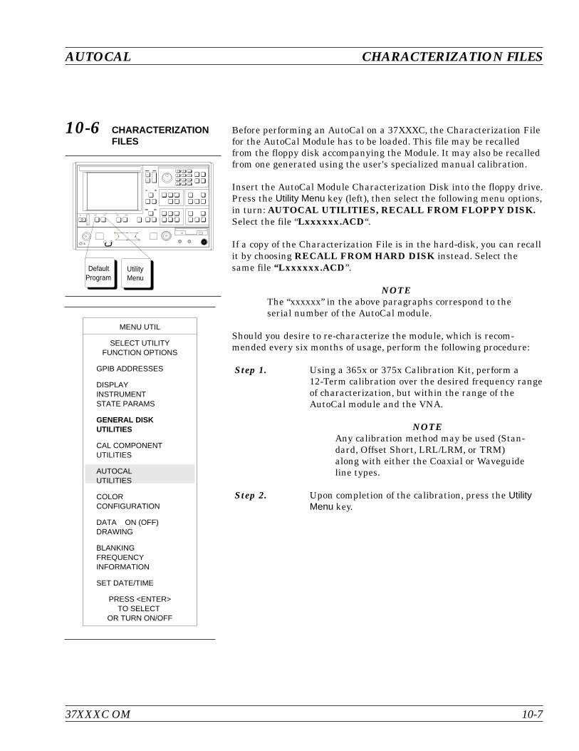
10-6 CHARACTERIZATIONFILES
Before performing an AutoCal on a 37XXXC, the Characterization Filefor the AutoCal Module has to be loaded. This file may be recalledfrom the floppy disk accompanying the Module. It may also be recalledfrom one generated using the user's specialized manual calibration.
Insert the AutoCal Module Characterization Disk into the floppy drive.Press the Utility Menu key (left), then select the following menu options,in turn: AUTOCAL UTILITIES, RECALL FROM FLOPPY DISK.Select the file “Lxxxxxx.ACD“.
If a copy of the Characterization File is in the hard-disk, you can recallit by choosing RECALL FROM HARD DISK instead. Select thesame file “Lxxxxxx.ACD”.
NOTEThe “xxxxxx” in the above paragraphs correspond to theserial number of the AutoCal module.
Should you desire to re-characterize the module, which is recom-mended every six months of usage, perform the following procedure:
Step 1. Using a 365x or 375x Calibration Kit, perform a12-Term calibration over the desired frequency rangeof characterization, but within the range of theAutoCal module and the VNA.
NOTEAny calibration method may be used (Stan-dard, Offset Short, LRL/LRM, or TRM)along with either the Coaxial or Waveguideline types.
Step 2. Upon completion of the calibration, press the UtilityMenu key.
37XXXC OM 10-7
AUTOCAL CHARACTERIZATION FILES
DefaultProgram
UtilityMenu
MENU UTIL
SELECT UTILITYFUNCTION OPTIONS
GPIB ADDRESSES
DISPLAYINSTRUMENTSTATE PARAMS
GENERAL DISKUTILITIES
CAL COMPONENTUTILITIES
AUTOCALUTILITIES
COLORCONFIGURATION
DATA ON (OFF)DRAWING
BLANKINGFREQUENCYINFORMATION
SET DATE/TIME
PRESS <ENTER>TO SELECT
OR TURN ON/OFF
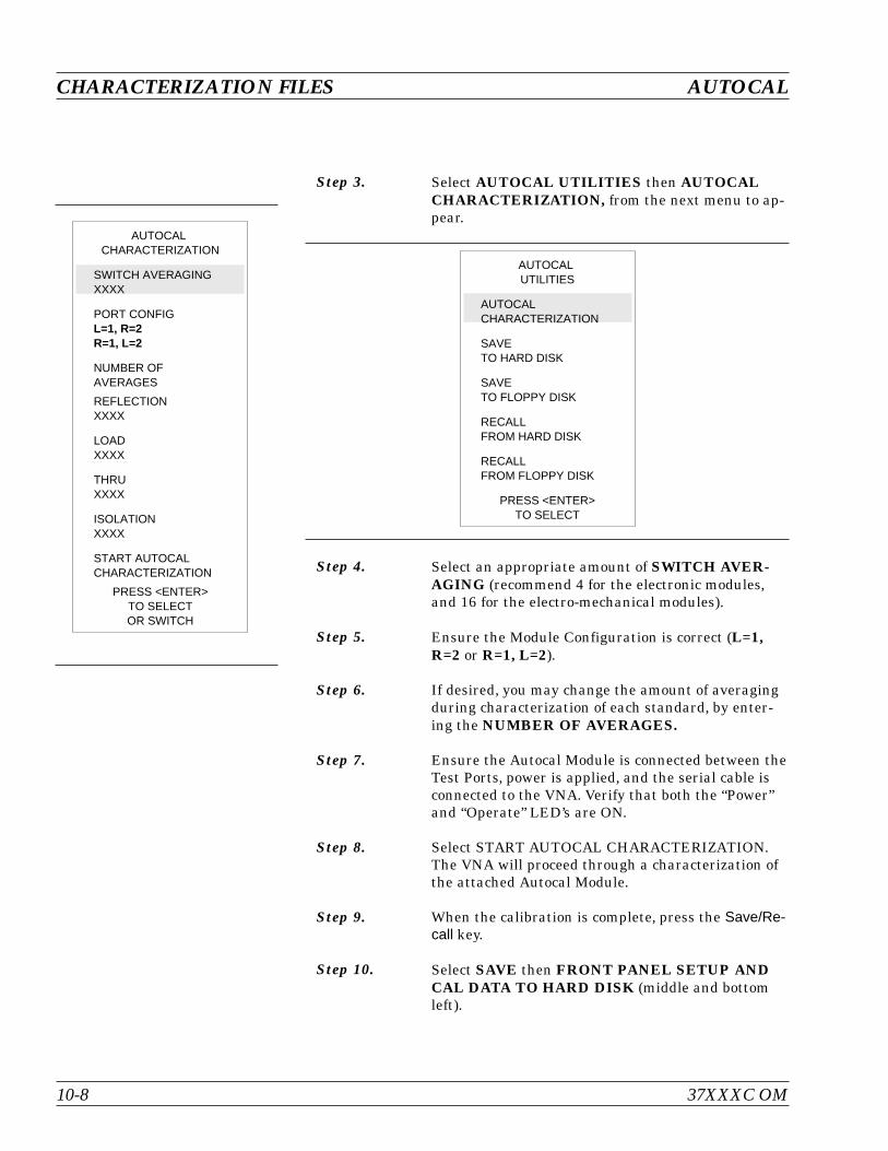
Step 3. Select AUTOCAL UTILITIES then AUTOCALCHARACTERIZATION, from the next menu to ap-pear.
Step 4. Select an appropriate amount of SWITCH AVER-AGING (recommend 4 for the electronic modules,and 16 for the electro-mechanical modules).
Step 5. Ensure the Module Configuration is correct (L=1,R=2 or R=1, L=2).
Step 6. If desired, you may change the amount of averagingduring characterization of each standard, by enter-ing the NUMBER OF AVERAGES.
Step 7. Ensure the Autocal Module is connected between theTest Ports, power is applied, and the serial cable isconnected to the VNA. Verify that both the “Power”and “Operate” LED’s are ON.
Step 8. Select START AUTOCAL CHARACTERIZATION.The VNA will proceed through a characterization ofthe attached Autocal Module.
Step 9. When the calibration is complete, press the Save/Re-call key.
Step 10. Select SAVE then FRONT PANEL SETUP ANDCAL DATA TO HARD DISK (middle and bottomleft).
CHARACTERIZATION FILES AUTOCAL
10-8 37XXXC OM
AUTOCALCHARACTERIZATION
SWITCH AVERAGINGXXXX
PORT CONFIGL=1, R=2R=1, L=2
NUMBER OFAVERAGES
REFLECTIONXXXX
LOADXXXX
THRUXXXX
ISOLATIONXXXX
START AUTOCALCHARACTERIZATION
PRESS <ENTER>TO SELECTOR SWITCH
AUTOCALUTILITIES
AUTOCALCHARACTERIZATION
SAVETO HARD DISK
SAVETO FLOPPY DISK
RECALLFROM HARD DISK
RECALLFROM FLOPPY DISK
PRESS <ENTER>TO SELECT
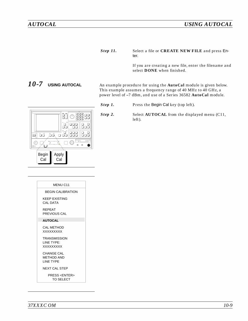
Step 11. Select a file or CREATE NEW FILE and press En-ter.
If you are creating a new file, enter the filename andselect DONE when finished.
10-7 USING AUTOCAL An example procedure for using the AutoCal module is given below.This example assumes a frequency range of 40 MHz to 40 GHz, apower level of 7 dBm, and use of a Series 36582 AutoCal module.
Step 1. Press the Begin Cal key (top left).
Step 2. Select AUTOCAL from the displayed menu (C11,left).
37XXXC OM 10-9
AUTOCAL USING AUTOCAL
ApplyCal
BeginCal
MENU C11
BEGIN CALIBRATION
KEEP EXISTINGCAL DATA
REPEATPREVIOUS CAL
AUTOCAL
CAL METHODXXXXXXXXX
TRANSMISSIONLINE TYPE:XXXXXXXXX
CHANGE CALMETHOD ANDLINE TYPE
NEXT CAL STEP
PRESS <ENTER>TO SELECT

Step 3. The selections in the next menu to appear, MENUACAL, will depend on current instrument conditions,as follows:
a. THRU UPDATE lets you update the Thru cali-bration of an active 12-term Calibration. Thisupdates the transmission frequency responseand load match coefficients.
b. START AUTOCAL lets you start a calibrationusing the current setup.
c. CHANGE AUTOCAL SETUP lets you set up anew calibration, which is what we will do forthis example. This example also assumes thatyou have selected the transmission medium and,if waveguide, identified the cutoff frequency.
USING AUTOCAL AUTOCAL
10-10 37XXXC OM
MENU ACAL
AUTOCAL
AUTOCAL TYPE:XXXXXXXX
CHANGEAUTOCAL SETUP
START AUTOCAL
THRU UPDATE
CONNECT THROUGHLINE BETWEENPORTS 1 AND 2
NUMBER OF AVGSXXX
START THRU UPDATE
USE PREVIOUSAUTOCAL SETUP
PRESS <ENTER>TO SELECTOR SWITCH
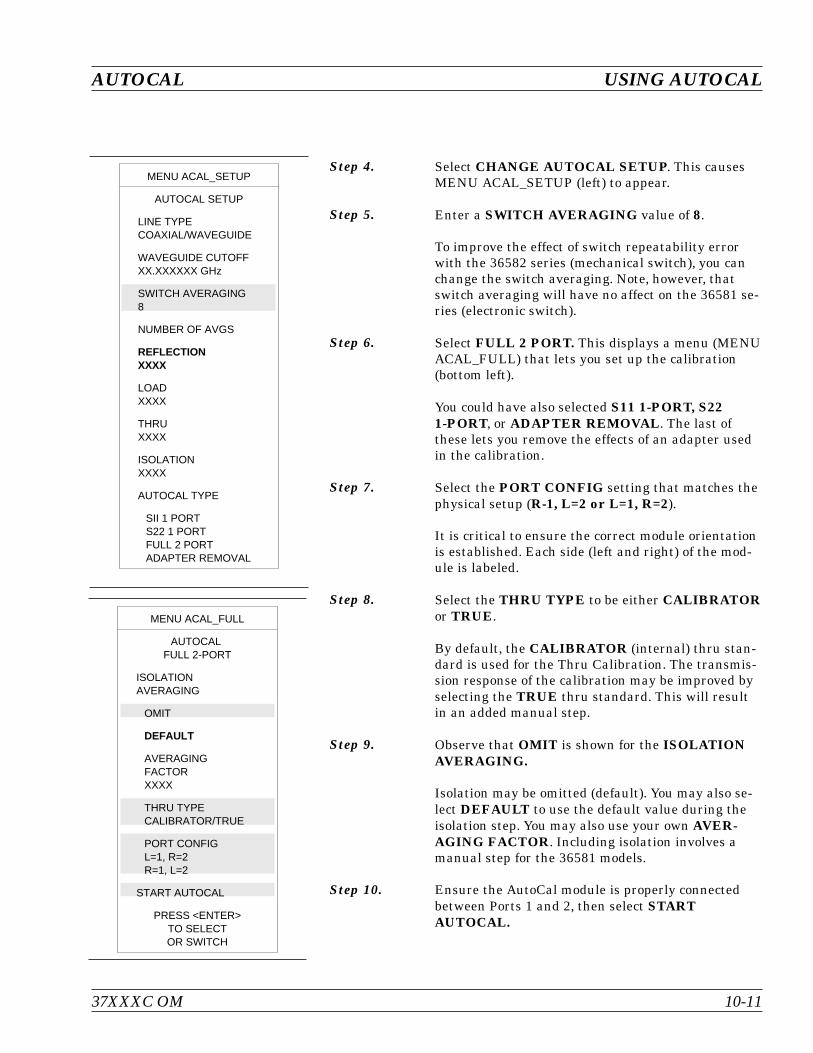
Step 4. Select CHANGE AUTOCAL SETUP. This causesMENU ACAL_SETUP (left) to appear.
Step 5. Enter a SWITCH AVERAGING value of 8.
To improve the effect of switch repeatability errorwith the 36582 series (mechanical switch), you canchange the switch averaging. Note, however, thatswitch averaging will have no affect on the 36581 se-ries (electronic switch).
Step 6. Select FULL 2 PORT. This displays a menu (MENUACAL_FULL) that lets you set up the calibration(bottom left).
You could have also selected S11 1-PORT, S221-PORT, or ADAPTER REMOVAL. The last ofthese lets you remove the effects of an adapter usedin the calibration.
Step 7. Select the PORT CONFIG setting that matches thephysical setup (R-1, L=2 or L=1, R=2).
It is critical to ensure the correct module orientationis established. Each side (left and right) of the mod-ule is labeled.
Step 8. Select the THRU TYPE to be either CALIBRATORor TRUE.
By default, the CALIBRATOR (internal) thru stan-dard is used for the Thru Calibration. The transmis-sion response of the calibration may be improved byselecting the TRUE thru standard. This will resultin an added manual step.
Step 9. Observe that OMIT is shown for the ISOLATIONAVERAGING.
Isolation may be omitted (default). You may also se-lect DEFAULT to use the default value during theisolation step. You may also use your own AVER-AGING FACTOR. Including isolation involves amanual step for the 36581 models.
Step 10. Ensure the AutoCal module is properly connectedbetween Ports 1 and 2, then select STARTAUTOCAL.
37XXXC OM 10-11
AUTOCAL USING AUTOCAL
MENU ACAL_SETUP
AUTOCAL SETUP
LINE TYPECOAXIAL/WAVEGUIDE
WAVEGUIDE CUTOFFXX.XXXXXX GHz
SWITCH AVERAGING8
NUMBER OF AVGS
REFLECTIONXXXX
LOADXXXX
THRUXXXX
ISOLATIONXXXX
AUTOCAL TYPE
SII 1 PORTS22 1 PORTFULL 2 PORTADAPTER REMOVAL
MENU ACAL_FULL
AUTOCALFULL 2-PORT
ISOLATIONAVERAGING
OMIT
DEFAULT
AVERAGINGFACTORXXXX
THRU TYPECALIBRATOR/TRUE
PORT CONFIGL=1, R=2R=1, L=2
START AUTOCAL
PRESS <ENTER>TO SELECTOR SWITCH
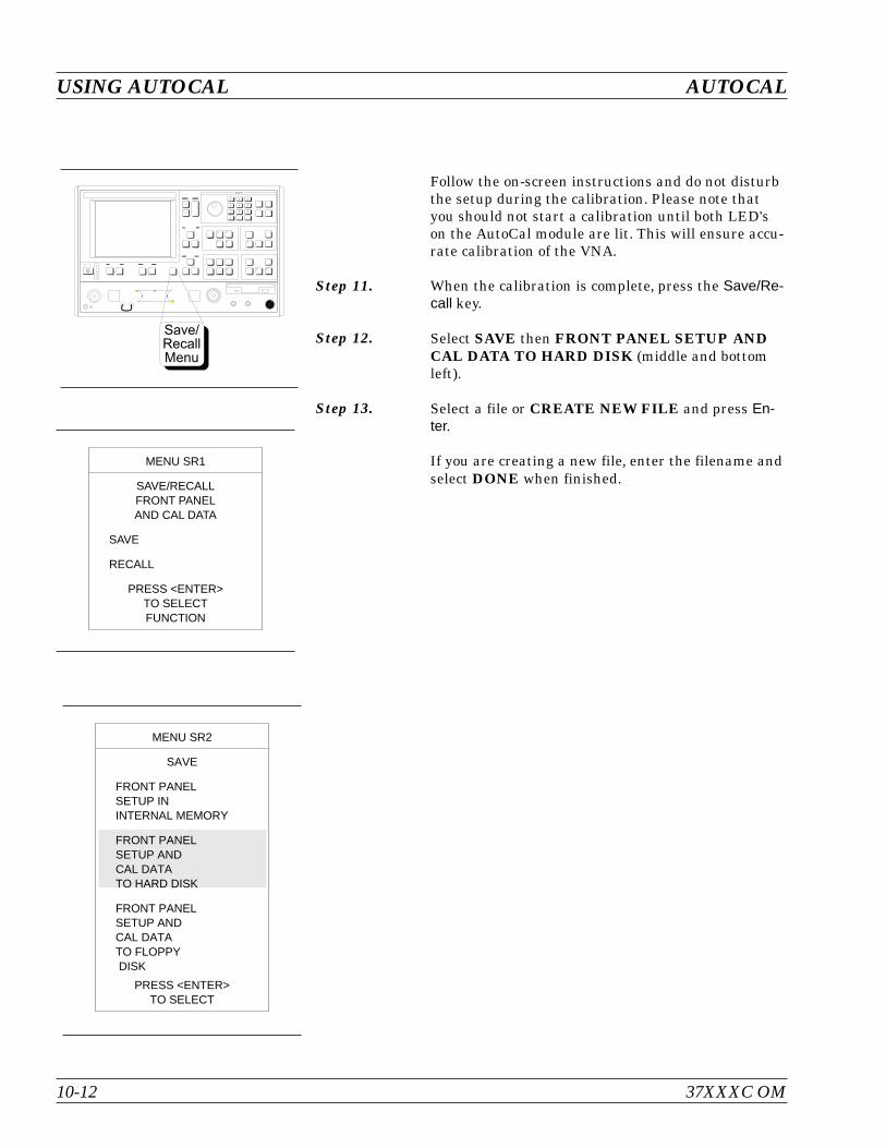
Follow the on-screen instructions and do not disturbthe setup during the calibration. Please note thatyou should not start a calibration until both LED'son the AutoCal module are lit. This will ensure accu-rate calibration of the VNA.
Step 11. When the calibration is complete, press the Save/Re-call key.
Step 12. Select SAVE then FRONT PANEL SETUP ANDCAL DATA TO HARD DISK (middle and bottomleft).
Step 13. Select a file or CREATE NEW FILE and press En-ter.
If you are creating a new file, enter the filename andselect DONE when finished.
10-12 37XXXC OM
USING AUTOCAL AUTOCAL
- B G
> 4 6
:
7 . 8
#
K $
MENU SR2
SAVE
FRONT PANELSETUP ININTERNAL MEMORY
FRONT PANELSETUP ANDCAL DATATO HARD DISK
FRONT PANELSETUP ANDCAL DATATO FLOPPYDISK
PRESS <ENTER>TO SELECT
MENU SR1
SAVE/RECALLFRONT PANELAND CAL DATA
SAVE
RECALL
PRESS <ENTER>TO SELECTFUNCTION
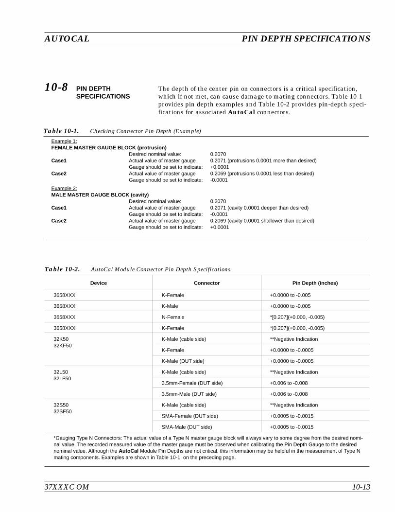
10-8 PIN DEPTHSPECIFICATIONS
The depth of the center pin on connectors is a critical specification,which if not met, can cause damage to mating connectors. Table 10-1provides pin depth examples and Table 10-2 provides pin-depth speci-fications for associated AutoCal connectors.
37XXXC OM 10-13
AUTOCAL PIN DEPTH SPECIFICATIONS
Example 1:FEMALE MASTER GAUGE BLOCK (protrusion)
Desired nominal value: 0.2070Case1 Actual value of master gauge 0.2071 (protrusions 0.0001 more than desired)
Gauge should be set to indicate: +0.0001Case2 Actual value of master gauge 0.2069 (protrusions 0.0001 less than desired)
Gauge should be set to indicate: -0.0001
Example 2:MALE MASTER GAUGE BLOCK (cavity)
Desired nominal value: 0.2070Case1 Actual value of master gauge 0.2071 (cavity 0.0001 deeper than desired)
Gauge should be set to indicate: -0.0001Case2 Actual value of master gauge 0.2069 (cavity 0.0001 shallower than desired)
Gauge should be set to indicate: +0.0001
Table 10-1. Checking Connector Pin Depth (Example)
Device Connector Pin Depth (inches)
3658XXX K-Female +0.0000 to -0.005
3658XXX K-Male +0.0000 to -0.005
3658XXX N-Female *[0.207](+0.000, -0.005)
3658XXX K-Female *[0.207](+0.000, -0.005)
32K5032KF50
K-Male (cable side) **Negative Indication
K-Female +0.0000 to -0.0005
K-Male (DUT side) +0.0000 to -0.0005
32L5032LF50
K-Male (cable side) **Negative Indication
3.5mm-Female (DUT side) +0.006 to -0.008
3.5mm-Male (DUT side) +0.006 to -0.008
32S5032SF50
K-Male (cable side) **Negative Indication
SMA-Female (DUT side) +0.0005 to -0.0015
SMA-Male (DUT side) +0.0005 to -0.0015
*Gauging Type N Connectors: The actual value of a Type N master gauge block will always vary to some degree from the desired nomi-nal value. The recorded measured value of the master gauge must be observed when calibrating the Pin Depth Gauge to the desirednominal value. Although the AutoCal Module Pin Depths are not critical, this information may be helpful in the measurement of Type Nmating components. Examples are shown in Table 10-1, on the preceding page.
Table 10-2. AutoCal Module Connector Pin Depth Specifications
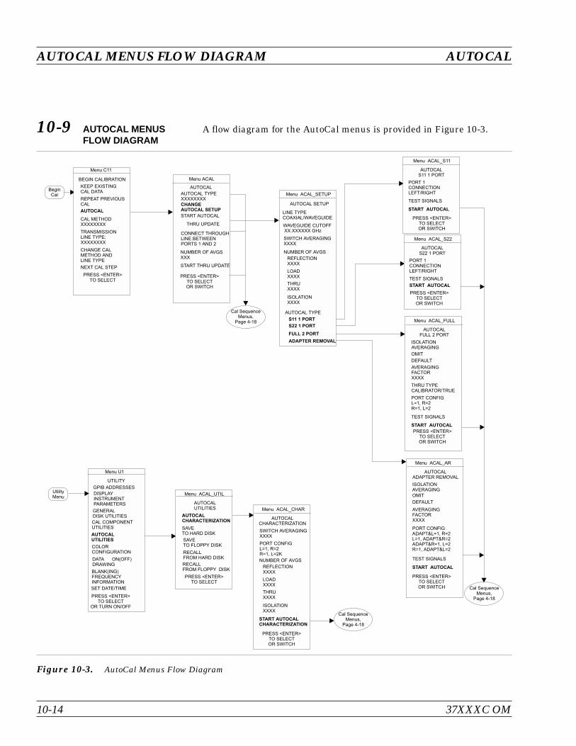
10-9 AUTOCAL MENUSFLOW DIAGRAM
A flow diagram for the AutoCal menus is provided in Figure 10-3.
AUTOCAL MENUS FLOW DIAGRAM AUTOCAL
10-14 37XXXC OM
Menu ACAL_SETUP
LINE TYPECOAXIAL/WAVEGUIDE
AUTOCAL SETUP
WAVEGUIDE CUTOFFXX.XXXXXX GHz
SWITCH AVERAGINGXXXX
AUTOCAL TYPE
S11 1 PORT
S22 1 PORT
FULL 2 PORT
ADAPTER REMOVAL
NUMBER OF AVGS
REFLECTIONXXXX
LOADXXXX
THRUXXXX
ISOLATIONXXXX
Menu C11
BEGIN CALIBRATION
KEEP EXISTINGCAL DATA
REPEAT PREVIOUSCAL
AUTOCAL
CAL METHODXXXXXXXX
TRANSMISSIONLINE TYPE:XXXXXXXX
CHANGE CALMETHOD ANDLINE TYPE
NEXT CAL STEP
PRESS <ENTER>TO SELECT
Menu ACAL
AUTOCAL
AUTOCAL TYPEXXXXXXXX
CHANGEAUTOCAL SETUP
START AUTOCAL
NUMBER OF AVGSXXX
START THRU UPDATE
THRU UPDATE
CONNECT THROUGHLINE BETWEENPORTS 1 AND 2
PRESS <ENTER>TO SELECTOR SWITCH
Menu ACAL_S11
AUTOCALS11 1 PORT
PORT 1CONNECTIONLEFT/RIGHT
START AUTOCAL
TEST SIGNALS
PRESS <ENTER>TO SELECTOR SWITCH
Menu ACAL_S22
AUTOCALS22 1 PORT
PORT 1CONNECTIONLEFT/RIGHT
START AUTOCAL
PRESS <ENTER>TO SELECTOR SWITCH
Menu ACAL_FULL
AUTOCALFULL 2 PORT
ISOLATIONAVERAGING
OMIT
DEFAULT
AVERAGINGFACTORXXXX
THRU TYPECALIBRATOR/TRUE
PORT CONFIGL=1, R=2R=1, L=2
START AUTOCAL
PRESS <ENTER>TO SELECTOR SWITCH
BeginCal
Cal SequenceMenus,
Page 4-18
Cal SequenceMenus,
Page 4-18
Menu ACAL_AR
AUTOCALADAPTER REMOVAL
ISOLATIONAVERAGING
OMIT
DEFAULT
AVERAGINGFACTORXXXX
PORT CONFIGADAPT&L=1, R=2L=1, ADAPT&R=2ADAPT&R=1, L=2R=1, ADAPT&L=2
START AUTOCAL
PRESS <ENTER>TO SELECTOR SWITCH
Menu U1
UTILITY
GPIB ADDRESSES
DISPLAYINSTRUMENTPARAMETERS
GENERALDISK UTILITIES
CAL COMPONENTUTILITIES
AUTOCALUTILITIES
COLORCONFIGURATION
DATA ON(OFF)DRAWING
BLANK(ING)FREQUENCYINFORMATION
SET DATE/TIME
PRESS <ENTER>TO SELECT
OR TURN ON/OFF
UtilityMenu
Cal SequenceMenus,
Page 4-18
Menu ACAL_UTIL
Menu ACAL_CHAR
AUTOCALUTILITIES
AUTOCALCHARACTERIZATION
AUTOCALCHARACTERIZATION
SWITCH AVERAGINGXXXX
SAVETO HARD DISK
PORT CONFIGL=1, R=2R=1, L=2KRECALL
FROM HARD DISK
RECALLFROM FLOPPY DISK
SAVETO FLOPPY DISK
PRESS <ENTER>TO SELECT
PRESS <ENTER>TO SELECTOR SWITCH
START AUTOCALCHARACTERIZATION
NUMBER OF AVGS
REFLECTIONXXXX
LOADXXXX
THRUXXXX
ISOLATIONXXXX
TEST SIGNALS
TEST SIGNALS
TEST SIGNALS
Figure 10-3. AutoCal Menus Flow Diagram
Table of Contents
11-1 INTRODUCTION. . . . . . . . . . . . . . . . . . . . . . . . . . . . . . . . . . . 11-3
11-2 REQUIRED EQUIPMENT. . . . . . . . . . . . . . . . . . . . . . . . . . . . . . 11-3
11-3 INITIAL SETUP . . . . . . . . . . . . . . . . . . . . . . . . . . . . . . . . . . . 11-3
11-4 SELF TEST . . . . . . . . . . . . . . . . . . . . . . . . . . . . . . . . . . . . . . 11-3
11-5 SAMPLER EFFICIENCY TEST . . . . . . . . . . . . . . . . . . . . . . . . . . . 11-4
11-6 HIGH LEVEL NOISE TEST . . . . . . . . . . . . . . . . . . . . . . . . . . . . . 11-8
Chapter 11Operational CheckoutProcedures: 371XXC

This equipment can not be repaired by the operator. DO NOT attempt toremove the equipment covers or to disassemble internal components.Only qualified service technicians with a knowledge of electrical fireand shock hazards should service this equipment. There arehigh-voltage parts in this equipment presenting a risk of severe injuryor fatal electric shock to untrained personnel. In addition, there is a riskof damage to precision components.
WARNING
Repair
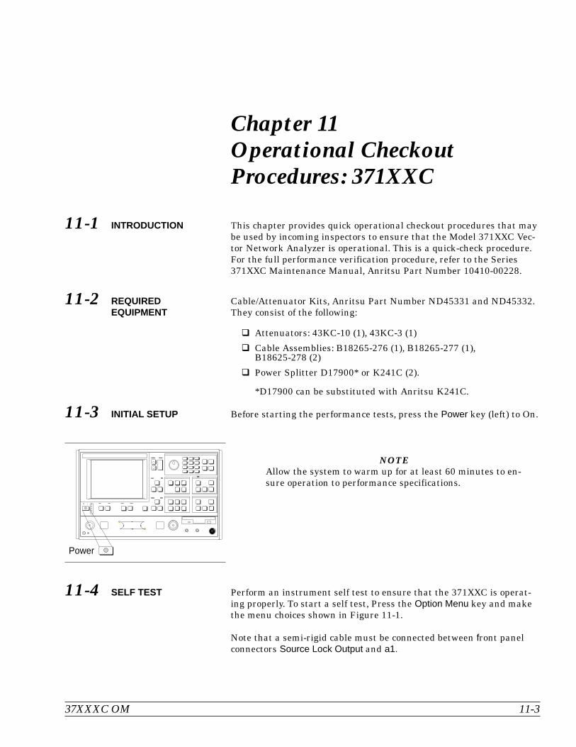
Chapter 11Operational CheckoutProcedures: 371XXC
11-1 INTRODUCTION This chapter provides quick operational checkout procedures that maybe used by incoming inspectors to ensure that the Model 371XXC Vec-tor Network Analyzer is operational. This is a quick-check procedure.For the full performance verification procedure, refer to the Series371XXC Maintenance Manual, Anritsu Part Number 10410-00228.
11-2 REQUIREDEQUIPMENT
Cable/Attenuator Kits, Anritsu Part Number ND45331 and ND45332.They consist of the following:
Attenuators: 43KC-10 (1), 43KC-3 (1)
Cable Assemblies: B18265-276 (1), B18265-277 (1),B18625-278 (2)
Power Splitter D17900* or K241C (2).
*D17900 can be substituted with Anritsu K241C.
11-3 INITIAL SETUP Before starting the performance tests, press the Power key (left) to On.
NOTEAllow the system to warm up for at least 60 minutes to en-sure operation to performance specifications.
11-4 SELF TEST Perform an instrument self test to ensure that the 371XXC is operat-ing properly. To start a self test, Press the Option Menu key and makethe menu choices shown in Figure 11-1.
Note that a semi-rigid cable must be connected between front panelconnectors Source Lock Output and a1.
37XXXC OM 11-3
Power
-

11-5 SAMPLER EFFICIENCYTEST
This test verifies that each individual receiver channel operates prop-erly. Measurement calibration of the system is not required for thistest.
This test requires that you press specified front panel keys and makechoices from the displayed menu(s). The keys used in this test areshown below:
SAMPLER EFFICIENCY TEST OPERATIONAL CHECKOUT
11-4 37XXXC OM
7 8 9
4 5 6
1 2 3
0 . -
Dat a Entr y
Figure 11-1. Performing a Self Test
OPTIONS
TRIGGERS
REAR PANELOUTPUT
DIAGNOSTICS
MULTIPLE SOURCECONTROL
RECEIVER MODE
SOURCE CONFIG
PRESS < ENTER>TO SELECT
DIAGNOSTICS
START SELF TEST
READ SERVICE LOG
INSTALLED OPTIONS
PERIPHERAL TESTS
TROUBLESHOOTING(FOR SERVICEUSE ONLY)
H/W CALIBRATIONS(FOR SERVICEUSE ONLY)
PRESS < Enter>
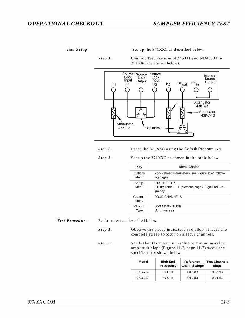
Test Setup Set up the 371XXC as described below.
Step 1. Connect Test Fixtures ND45331 and ND45332 to371XXC (as shown below).
Step 2. Reset the 371XXC using the Default Program key.
Step 3. Set up the 371XXC as shown in the table below.
Test Procedure Perform test as described below.
Step 1. Observe the sweep indicators and allow at least onecomplete sweep to occur on all four channels.
Step 2. Verify that the maximum-value to minimum-valueamplitude slope (Figure 11-3, page 11-7) meets thespecifications shown below.
37XXXC OM 11-5
OPERATIONAL CHECKOUT SAMPLER EFFICIENCY TEST
Key Menu Choice
OptionsMenu
Non-Ratioed Parameters, see Figure 11-2 (follow-ing page)
SetupMenu
START: 1 GHzSTOP: Table 11-1 (previous page), High-End Fre-quency
ChannelMenu
FOUR CHANNELS
GraphType
LOG MAGNITUDE(All channels)
Model High-EndFrequency
ReferenceChannel Slope
Test ChannelsSlope
37147C 20 GHz 10 dB 12 dB
37169C 40 GHz 12 dB 14 dB
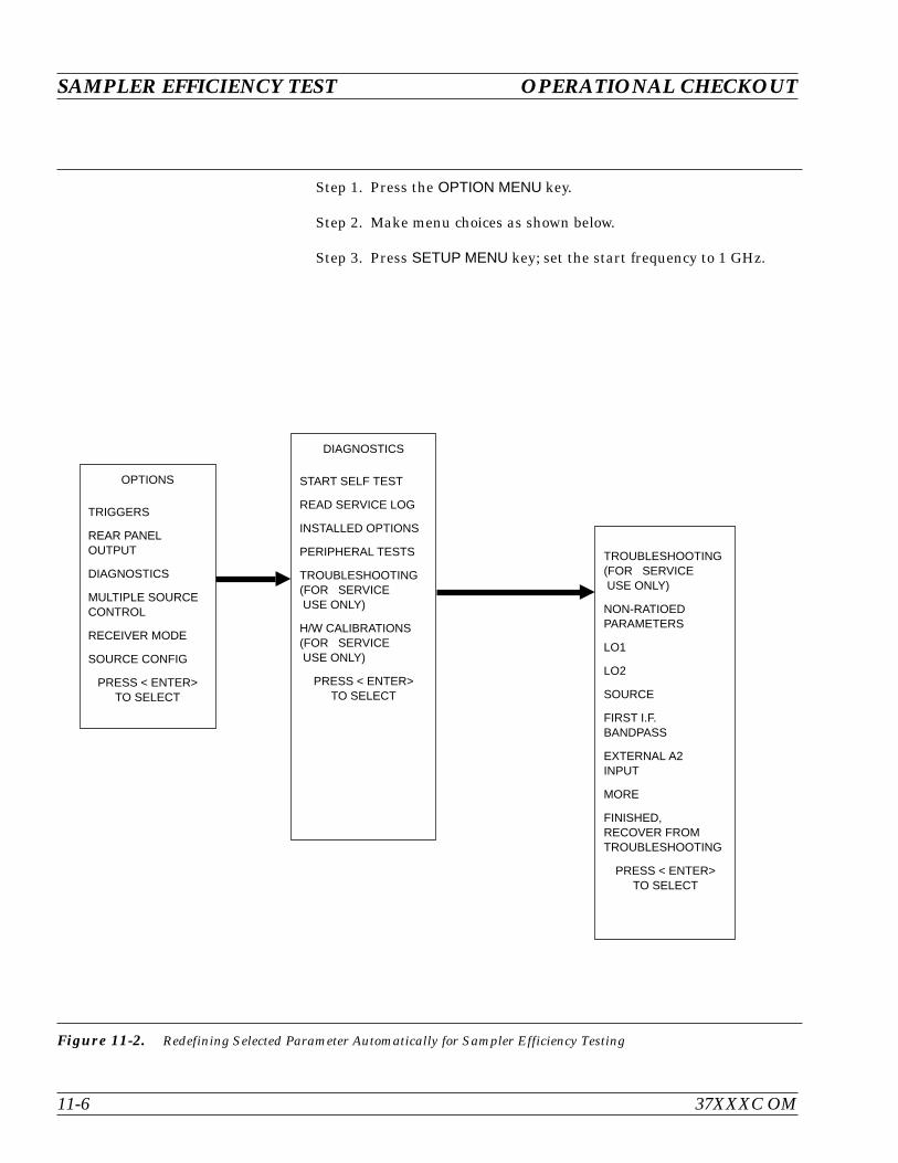
SAMPLER EFFICIENCY TEST OPERATIONAL CHECKOUT
11-6 37XXXC OM
Step 1. Press the OPTION MENU key.
Step 2. Make menu choices as shown below.
Step 3. Press SETUP MENU key; set the start frequency to 1 GHz.
Figure 11-2. Redefining Selected Parameter Automatically for Sampler Efficiency Testing
OPTIONS
TRIGGERS
REAR PANELOUTPUT
DIAGNOSTICS
MULTIPLE SOURCECONTROL
RECEIVER MODE
SOURCE CONFIG
PRESS < ENTER>TO SELECT
DIAGNOSTICS
START SELF TEST
READ SERVICE LOG
INSTALLED OPTIONS
PERIPHERAL TESTS
TROUBLESHOOTING(FOR SERVICEUSE ONLY)
H/W CALIBRATIONS(FOR SERVICEUSE ONLY)
PRESS < ENTER>TO SELECT
TROUBLESHOOTING(FOR SERVICEUSE ONLY)
NON-RATIOEDPARAMETERS
LO1
LO2
SOURCE
FIRST I.F.BANDPASS
EXTERNAL A2INPUT
MORE
FINISHED,RECOVER FROMTROUBLESHOOTING
PRESS < ENTER>TO SELECT
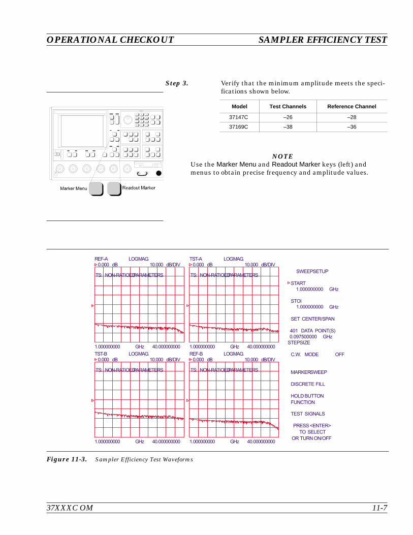
Step 3. Verify that the minimum amplitude meets the speci-fications shown below.
NOTEUse the Marker Menu and Readout Marker keys (left) andmenus to obtain precise frequency and amplitude values.
37XXXC OM 11-7
OPERATIONAL CHECKOUT SAMPLER EFFICIENCY TEST
7 8 9
4 5 6
1 2 3
0 . -
Dat a Entr y
TS: NON-RATIOEDPARAMETERS TS: NON-RATIOEDPARAMETERS
TS: NON-RATIOEDPARAMETERS TS: NON-RATIOEDPARAMETERS
START
1
1
.
.
0
0
0
0
0
0
0
0
0
0
0
0
0
0
0
0
0
0
GHz
STOP
GHz
SET CENTER/SPAN
C.W. MODE OFF
MARKERSWEEP
DISCRETE FILL
HOLD BUTTON
FUNCTION
TEST SIGNALS
GHz1.000000000 40.000000000
REF-A LOGMAG.0.000 dB 10.000 dB/DIV
GHz1.000000000 40.000000000
TST-A LOGMAG.0.000 dB 10.000 dB/DIV
GHz1.000000000 40.000000000
TST-B LOGMAG.0.000 dB 10.000 dB/DIV
GHz1.000000000 40.000000000
REF-B LOGMAG.0.000 dB 10.000 dB/DIV
SWEEPSETUP
401 DATA POINT(S)
STEPSIZE
0.097500000 GHz
PRESS<ENTER>
TO SELECT
OR TURN ON/OFF
Figure 11-3. Sampler Efficiency Test Waveforms
Model Test Channels Reference Channel
37147C –26 –28
37169C –38 –36
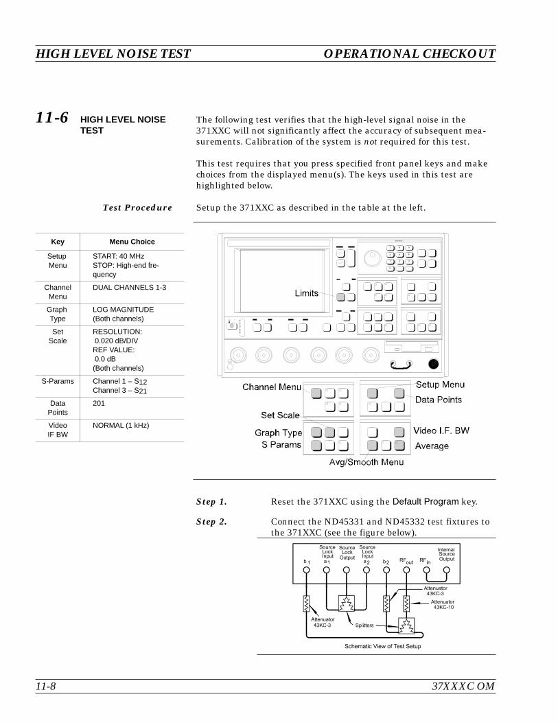
11-6 HIGH LEVEL NOISETEST
The following test verifies that the high-level signal noise in the371XXC will not significantly affect the accuracy of subsequent mea-surements. Calibration of the system is not required for this test.
This test requires that you press specified front panel keys and makechoices from the displayed menu(s). The keys used in this test arehighlighted below.
Test Procedure Setup the 371XXC as described in the table at the left.
Step 1. Reset the 371XXC using the Default Program key.
Step 2. Connect the ND45331 and ND45332 test fixtures tothe 371XXC (see the figure below).
HIGH LEVEL NOISE TEST OPERATIONAL CHECKOUT
11-8 37XXXC OM
Key Menu Choice
SetupMenu
START: 40 MHzSTOP: High-end fre-quency
ChannelMenu
DUAL CHANNELS 1-3
GraphType
LOG MAGNITUDE(Both channels)
SetScale
RESOLUTION:0.020 dB/DIVREF VALUE:0.0 dB(Both channels)
S-Params Channel 1 – S12Channel 3 – S21
DataPoints
201
VideoIF BW
NORMAL (1 kHz)
7 8 9
4 5 6
1 2 3
0 . -
Dat a Entr y

Step 3. Press the Ch 1 key.
Step 4. Press the Trace Memory key.
Step 5. Choose VIEW DATA from the menu and press theEnter key.
Step 6. While observing the sweep indicators, allow at leasttwo complete sweeps to occur.
Step 7. Choose STORE DATA TO MEMORY from themenu and press the Enter key.
Step 8. Choose VIEW DATA / MEMORY from menu andpress the Enter key.
Step 9. While observing the sweep indicators, allow at leasttwo complete sweeps to occur.
Step 10. Verify that the peak-to-peak High Level Noise fallswithin the area between the two limit lines(Figure 11-4, following page).
Step 11. Press the Ch 3 key.
Step 12. Repeat Steps 4 through 9 for Channel 3.
37XXXC OM 11-9
OPERATIONAL CHECKOUT HIGH LEVEL NOISE TEST
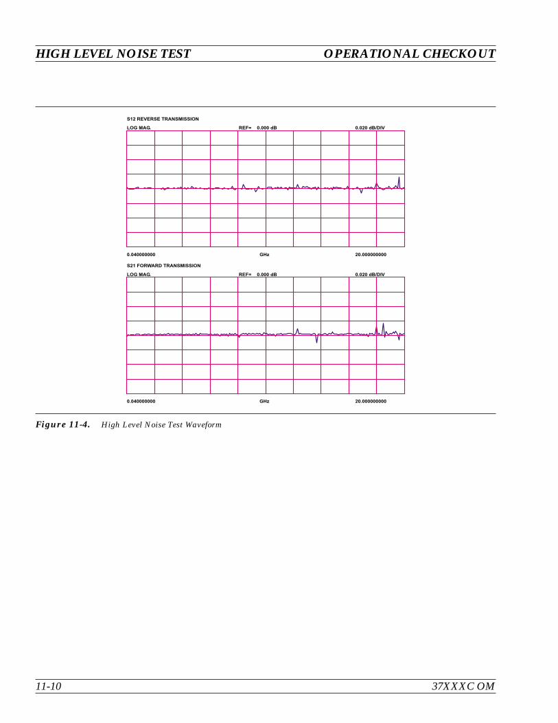
HIGH LEVEL NOISE TEST OPERATIONAL CHECKOUT
11-10 37XXXC OM
GHz0.040000000 20.000000000
S12 REVERSE TRANSMISSION
LOG MAG. REF= 0.000 dB 0.020 dB/DIV
GHz0.040000000 20.000000000
S21 FORWARD TRANSMISSION
LOG MAG. REF= 0.000 dB 0.020 dB/DIV
Figure 11-4. High Level Noise Test Waveform
Table of Contents
12-1 INTRODUCTION. . . . . . . . . . . . . . . . . . . . . . . . . . . . . . . . . . . 12-3
12-2 REQUIRED EQUIPMENT. . . . . . . . . . . . . . . . . . . . . . . . . . . . . . 12-3
12-3 INITIAL SETUP . . . . . . . . . . . . . . . . . . . . . . . . . . . . . . . . . . . 12-3
12-4 SELF TEST . . . . . . . . . . . . . . . . . . . . . . . . . . . . . . . . . . . . . . 12-3
12-5 NON-RATIO POWER . . . . . . . . . . . . . . . . . . . . . . . . . . . . . . . . 12-4
12-6 HIGH LEVEL NOISE TEST . . . . . . . . . . . . . . . . . . . . . . . . . . . . . 12-6
Chapter 12Operational CheckoutProcedures: 372XXC, 373XXC
This equipment can not be repaired by the operator. DO NOT attempt toremove the equipment covers or to disassemble internal components.Only qualified service technicians with a knowledge of electrical fireand shock hazards should service this equipment. There arehigh-voltage parts in this equipment presenting a risk of severe injuryor fatal electric shock to untrained personnel. In addition, there is a riskof damage to precision components.
WARNING
Repair

Chapter 12Operational CheckoutProcedures: 372XXC, 373XXC
12-1 INTRODUCTION This chapter provides quick operational checkout procedures that maybe used by incoming inspectors to ensure that the Model 37XXXC Vec-tor Network Analyzer is operational. This is a quick-check procedure.For the full performance verification procedure, refer to the Series37XXXC Maintenance Manual, Anritsu Part Number 10410-00228.
12-2 REQUIREDEQUIPMENT
The following equipment is required for the procedures in this chapter:
Flexible microwave cable (through line)
Short
12-3 INITIAL SETUP Before starting the performance tests, press the Power key (left) to On.
NOTEAllow the system to warm up for at least 60 minutes to en-sure operation to performance specifications.
12-4 SELF TEST Perform an instrument self test to ensure that the VNA is operatingproperly. To start a self test, Press the Option Menu key and make themenu choices shown in Figure 12-1.
37XXXC OM 12-3
Power
-
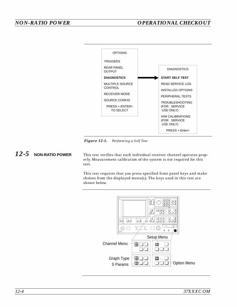
12-5 NON-RATIO POWER This test verifies that each individual receiver channel operates prop-erly. Measurement calibration of the system is not required for thistest.
This test requires that you press specified front panel keys and makechoices from the displayed menu(s). The keys used in this test areshown below.
NON-RATIO POWER OPERATIONAL CHECKOUT
12-4 37XXXC OM
Figure 12-1. Performing a Self Test
OPTIONS
TRIGGERS
REAR PANELOUTPUT
DIAGNOSTICS
MULTIPLE SOURCECONTROL
RECEIVER MODE
SOURCE CONFIG
PRESS < ENTER>TO SELECT
DIAGNOSTICS
START SELF TEST
READ SERVICE LOG
INSTALLED OPTIONS
PERIPHERAL TESTS
TROUBLESHOOTING(FOR SERVICEUSE ONLY)
H/W CALIBRATIONS(FOR SERVICEUSE ONLY)
PRESS < Enter>
Channel Menu
Graph Type
S Params
Setup Menu
Option Menu
-

Test Procedure Perform test as described below.
Step 1. Connect Test Ports 1 and 2 together using ahigh-quality through line (below).
Step 2. Reset the VNA using the Default Program key.
Step 3. Set up the VNA as shown in table at left.
Step 4. Observe the sweep indicators and allow at least onecomplete sweep to occur on all four channels.
Step 5. Verify that the minimum amplitude meets the speci-fications shown below.
Model Test Channel Reference Channel
37217C >28 dB >35 dB
37317C >28 dB >35 dB
37225C >25 dB >34 dB
37325C >30 dB >32 dB
37247C >26 dB >35 dB
37347C >31 dB >33 dB
37269C >40 dB >40 dB
37369C >34 dB >34 dB
37277C >45 dB >45 dB
37377C >45 dB >45 dB
37297C >60 dB >55 dB
37397C >60 dB >55 dB
NOTEUse the Marker Menu and Readout Marker keys ( left) andmenus to obtain precise frequency and amplitude values.
37XXXC OM 12-5
OPERATIONAL CHECKOUT NON-RATIO POWER
POR T 1 POR T 2
TE ST P ORT 1
TEST PORT 2
Key Menu Choice
OptionsMenu
Non-Ratioed Parameters,see Figure 11-2
SetupMenu
START: 1 GHzSTOP: High-End Fre-quency
ChannelMenu
FOUR CHANNELS
GraphType
LOG MAGNITUDE(All channels)
S-PARAMS USER 1: (Channel 3)Parameter: Ra/1Phase Lock: Ra
USER 2: (Channel 1)Parameter: Ta/1Phase Lock: Ra
USER 3: (Channel 2)Parameter: Tb/1Phase Lock: Ra
USER 4: (Channel 4)Parameter: Rb/1Phase Lock: Rb
SETSCALE
RESOLUTION:20 dB/DIVREF VALUE:0 dB(All four channels)
-
Marker Menu Readout Marker
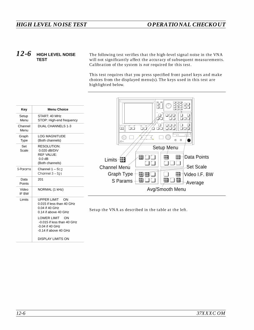
12-6 HIGH LEVEL NOISETEST
The following test verifies that the high-level signal noise in the VNAwill not significantly affect the accuracy of subsequent measurements.Calibration of the system is not required for this test.
This test requires that you press specified front panel keys and makechoices from the displayed menu(s). The keys used in this test arehighlighted below.
Setup the VNA as described in the table at the left.
HIGH LEVEL NOISE TEST OPERATIONAL CHECKOUT
12-6 37XXXC OM
Key Menu Choice
SetupMenu
START: 40 MHzSTOP: High-end frequency
ChannelMenu
DUAL CHANNELS 1-3
GraphType
LOG MAGNITUDE(Both channels)
SetScale
RESOLUTION:0.020 dB/DIVREF VALUE:0.0 dB(Both channels)
S-Params Channel 1 – S12Channel 3 – S21
DataPoints
201
VideoIF BW
NORMAL (1 kHz)
Limits UPPER LIMIT ON0.015 if less than 40 GHz0.04 if 40 GHz0.14 if above 40 GHz
LOWER LIMIT ON-0.015 if less than 40 GHz-0.04 if 40 GHz-0.14 if above 40 GHz
DISPLAY LIMITS ON
Channel MenuGraph Type
S Params
Setup Menu
Video I.F. BW
Data Points
AverageAvg/Smooth Menu
Set ScaleLimits
-
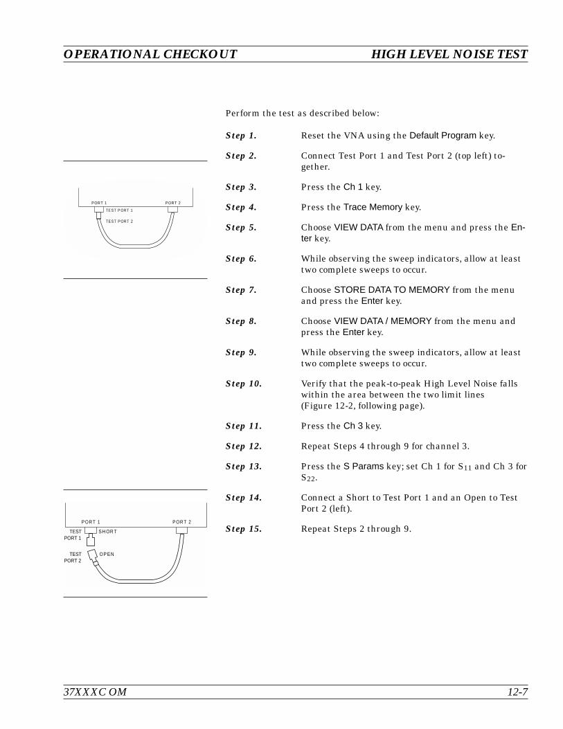
Perform the test as described below:
Step 1. Reset the VNA using the Default Program key.
Step 2. Connect Test Port 1 and Test Port 2 (top left) to-gether.
Step 3. Press the Ch 1 key.
Step 4. Press the Trace Memory key.
Step 5. Choose VIEW DATA from the menu and press the En-ter key.
Step 6. While observing the sweep indicators, allow at leasttwo complete sweeps to occur.
Step 7. Choose STORE DATA TO MEMORY from the menuand press the Enter key.
Step 8. Choose VIEW DATA / MEMORY from the menu andpress the Enter key.
Step 9. While observing the sweep indicators, allow at leasttwo complete sweeps to occur.
Step 10. Verify that the peak-to-peak High Level Noise fallswithin the area between the two limit lines(Figure 12-2, following page).
Step 11. Press the Ch 3 key.
Step 12. Repeat Steps 4 through 9 for channel 3.
Step 13. Press the S Params key; set Ch 1 for S11 and Ch 3 forS22.
Step 14. Connect a Short to Test Port 1 and an Open to TestPort 2 (left).
Step 15. Repeat Steps 2 through 9.
37XXXC OM 12-7
OPERATIONAL CHECKOUT HIGH LEVEL NOISE TEST
POR T 1 POR T 2
TE ST P ORT 1
TEST PORT 2
P OR T 1 P OR T 2
SH OR T
O P EN
TESTPORT 1
TESTPORT 2

HIGH LEVEL NOISE TEST OPERATIONAL CHECKOUT
12-8 37XXXC OM
GHz0.040000000 20.000000000
S12 REVERSE TRANSMISSION
LOG MAG. REF= 0.000 dB 0.020 dB/DIV
GHz0.040000000 20.000000000
S21 FORWARD TRANSMISSION
LOG MAG. REF= 0.000 dB 0.020 dB/DIV
Figure 12-2. High Level Noise Test Waveform
Table of Contents
13-1 INTRODUCTION. . . . . . . . . . . . . . . . . . . . . . . . . . . . . . . . . . . 13-3
13-2 PURPOSE. . . . . . . . . . . . . . . . . . . . . . . . . . . . . . . . . . . . . . . 13-3
13-3 KIT CONTENTS . . . . . . . . . . . . . . . . . . . . . . . . . . . . . . . . . . . 13-3
Model 3650 Calibration Kit . . . . . . . . . . . . . . . . . . . . . . . . . . . . 13-4
Model 3651 Calibration Kit . . . . . . . . . . . . . . . . . . . . . . . . . . . . 13-5
Model 3652 Calibration Kit . . . . . . . . . . . . . . . . . . . . . . . . . . . . 13-6
Model 3653 Calibration Kit . . . . . . . . . . . . . . . . . . . . . . . . . . . . 13-7
Model 3654/ 3654B Calibration Kit . . . . . . . . . . . . . . . . . . . . . . . . 13-8
Model 3656 Calibration Kit . . . . . . . . . . . . . . . . . . . . . . . . . . . . 13-9
13-4 PRECAUTIONS . . . . . . . . . . . . . . . . . . . . . . . . . . . . . . . . . . . 13-10
Pin Depth . . . . . . . . . . . . . . . . . . . . . . . . . . . . . . . . . . . . . 13-10
Pin Depth Tolerance . . . . . . . . . . . . . . . . . . . . . . . . . . . . . . . 13-11
Over Torquing Connectors . . . . . . . . . . . . . . . . . . . . . . . . . . . . 13-11
Teflon Tuning Washers. . . . . . . . . . . . . . . . . . . . . . . . . . . . . . 13-11
Mechanical Shock . . . . . . . . . . . . . . . . . . . . . . . . . . . . . . . . 13-11
13-5 CLEANING INSTRUCTIONS . . . . . . . . . . . . . . . . . . . . . . . . . . . 13-12
Chapter 13Calibration Kits

Chapter 13Calibration Kits
13-1 INTRODUCTION This chapter provides illustrations and contents for the Models 3650,3651, 3652, 3653, 3654/3654B, 36550 and 36552 Calibration Kits.
13-2 PURPOSE The calibration kits contain all of the precision components and toolsrequired to calibrate the 37XXXC Vector Network Analyzer System fora 12-term error-corrected measurement.
13-3 KIT CONTENTS The contents and illustrations of the calibration kits are listed on thefollowing pages.
37XXXC OM 13-3

Model 3650 Calibration Kit
KIT CONTENTS CALIBRATION KITS
13-4 37XXXC OM
* Phase Equal Adapters
Index Anritsu PartNumber
Description Qty.
1 01-212 Female Flush Short (Option 1) 1
2 01-211 Male Flush Short (Option 1) 1
3 17SF50 Female Sliding Termination 1
4 17S50 Male Sliding Termination (Option 1) 1
5 34ASF50-2 Female Adapter 2
6 Calibration Software Diskette 1
7 33FSF50 Female-Female Adapter 2
8 33SS50 Male-Male Adapter* 1
9 28S50-2 Male Termination 2
10 28SF50-2 Broadband Female Termination 2
11 33SSF50 Male-Female Adapter* 2
12 24S50 Male Open 1
13 23SF50 Female Open 1
14 23S50 Male Short 1
15 23SF50 Female Short 1
16 34AS50-2 Male Adapter 2
17 Connector Thumb Wheel 4
18 01-201 Torque Wrench 1
19 01-210 Reference Flat 1
20 01-222 Pin Depth Gauge 1
21 01-223 Pin Depth Gauge 1
Table 13-1. Model 3650 (SMA/3.5 mm) Calibration Kit Contents
WILTRON MODEL 3650
21
22
8
7
6
1918
17 16 13 1215 14 11 9
3
1
2
4
5
10
*
*
*
Figure 13-1. Model 3650 (SMA/3.5 mm) Calibration Kit Components
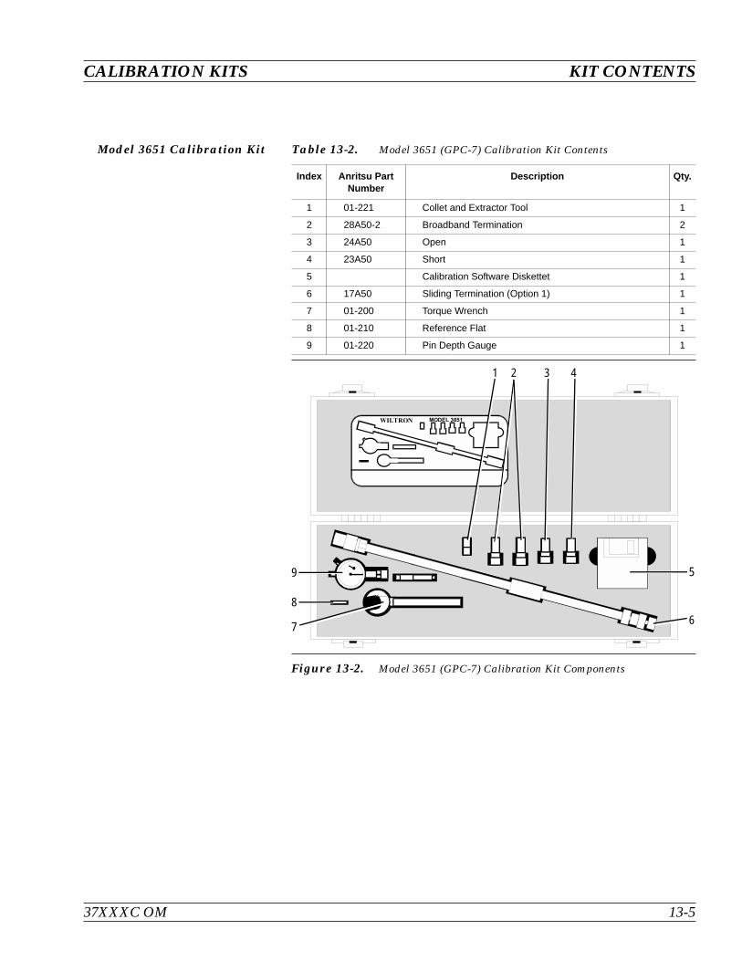
Model 3651 Calibration Kit
37XXXC OM 13-5
CALIBRATION KITS KIT CONTENTS
Index Anritsu PartNumber
Description Qty.
1 01-221 Collet and Extractor Tool 1
2 28A50-2 Broadband Termination 2
3 24A50 Open 1
4 23A50 Short 1
5 Calibration Software Diskettet 1
6 17A50 Sliding Termination (Option 1) 1
7 01-200 Torque Wrench 1
8 01-210 Reference Flat 1
9 01-220 Pin Depth Gauge 1
Table 13-2. Model 3651 (GPC-7) Calibration Kit Contents
WILTRON MODEL 3651
1 2 3 4
5
67
8
9
Figure 13-2. Model 3651 (GPC-7) Calibration Kit Components

Model 3652 Calibration Kit
KIT CONTENTS CALIBRATION KITS
13-6 37XXXC OM
Index Anritsu PartNumber
Description Qty.
1 01-212 Female Flush Short (Option 1) 1
2 01-211 Male Flush Short (Option 1) 1
3 17KF50 Female Sliding Termination 1
4 17K50 Male Sliding Termination (Option 1) 1
5 34AKF50-2 Female Adapter 2
6 Calibration Software Diskette 1
7 33FKF50 Female-Female Adapter 2
8 33KK50 Male-Male Adapter* 1
9 28K50-2 Male Termination 2
10 28KF50-2 Broadband Female Termination 2
11 33KKF50 Male-Female Adapter* 2
12 24K50 Male Open 1
13 23KF50 Female Open 1
14 23K50 Male Short 1
15 23KF50 Female Short 1
16 34AK50-2 Male Adapter 2
17 Connector Thumb Wheel 4
18 01-201 Torque Wrench 1
19 01-210 Reference Flat 1
20 01-222 Pin Depth Gauge 1
21 01-223 Pin Depth Gauge 1
Table 13-3. Model 3652 (K-Connector) Calibration Kit Contents
WILTRON MODEL 3652
21
22
8
7
6
1918
17 16 13 1215 14 11 9
3
1
2
4
5
10
*
*
*
Figure 13-3. Model 3652 (K-Connector) Calibration Kit Components
* Phase Equal Adapters

Model 3653 Calibration Kit
37XXXC OM 13-7
CALIBRATION KITS KIT CONTENTS
Index Anritsu PartNumber
Description Qty.
1 28N50-2 Broadband Male Termination 2
2 34AN50-2 Male Adapter 2
3 Calibration Software Diskette 1
4 34ANF50-2 Female Adapter 2
5 28NF50-2B Braodband Female Termination 2
6 24NF50 Female Open 1
7 24N50 Male Open 1
8 23NF50 Female Short 1
9 23N50 Male Short 1
10 01-213 Reference Gauge 1
11 01-224 Pin Depth Gauge 1
Table 13-4. Model 3653 (Type N) Calibration Kit Contents
. &
7 G B - 6 4 >
:
Figure 13-4. Model 3653 (Type N) Calibration Kit Components
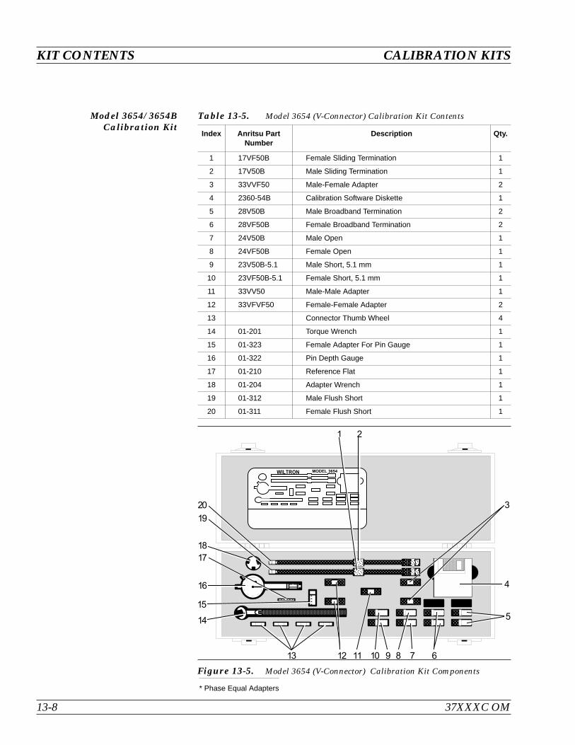
Model 3654/ 3654BCalibration Kit
KIT CONTENTS CALIBRATION KITS
13-8 37XXXC OM
* Phase Equal Adapters
Index Anritsu PartNumber
Description Qty.
1 17VF50B Female Sliding Termination 1
2 17V50B Male Sliding Termination 1
3 33VVF50 Male-Female Adapter 2
4 2360-54B Calibration Software Diskette 1
5 28V50B Male Broadband Termination 2
6 28VF50B Female Broadband Termination 2
7 24V50B Male Open 1
8 24VF50B Female Open 1
9 23V50B-5.1 Male Short, 5.1 mm 1
10 23VF50B-5.1 Female Short, 5.1 mm 1
11 33VV50 Male-Male Adapter 1
12 33VFVF50 Female-Female Adapter 2
13 Connector Thumb Wheel 4
14 01-201 Torque Wrench 1
15 01-323 Female Adapter For Pin Gauge 1
16 01-322 Pin Depth Gauge 1
17 01-210 Reference Flat 1
18 01-204 Adapter Wrench 1
19 01-312 Male Flush Short 1
20 01-311 Female Flush Short 1
Table 13-5. Model 3654 (V-Connector) Calibration Kit Contents
. & #
7
G
B
-
6
4
>
: 7 G B - 6
4
>
:
Figure 13-5. Model 3654 (V-Connector) Calibration Kit Components

Model 3656 Calibration Kit
37XXXC OM 13-9
CALIBRATION KITS KIT CONTENTS
Figure 13-6. Model 3656 (W1-Connector) Calibration Kit Components
Index AnritsuPart Number
Description Qty.
1 23W50-123W50-223W50-3
Male Offset Short 1 (2.02 mm)Male Offset Short 2 (2.65 mm)Male Offset Short 3 (3.180 mm)
111
2 24W50 Male Open (1.510 mm) 1
3 28W50 Male Broadband Termination 1
4 23WF50-123WF50-223WF50-3
Female Offset Short 1 (2.02 mm)Female Offset Short 2 (2.65 mm)Female Offset Short 3 (3.180 mm)
111
5 28WF50 Female Broadband Termination 1
6 24WF50 Female Open (1.930 mm) 1
7 33WSC50 Fixed Male SC Connector 1
8 33WFSC50 Fixed Female SC Connector 1
9 Interchangeable Sliders, SC Connectors 1
10 Locking Keys, SC Connectors 1
11 01-402 Interchangeable Adapter Fixed Male 1
12 33WWF50 Male-Female Adapter 1
13 33WW50 Male-Male Adapter 1
14 33WFWF50 Female-Female Adapter 1
15 01-504 6 mm Torque Wrench 1
16 01-505 6x7 mm End Wrench 1
17 18-WWF50-1B Stepped Impedance Thruline (Verification Device) 1
18 18-WWF50-1 50 Matched Thruline (Verification Device) 1
19 Calibration/Verification Software
Table 13-6. Model 3656 (W1-Connector) Calibration Kit Contents

13-4 PRECAUTIONS The following are precautionary notes related to the use of connectors.For specific information on setting pin depths on sliding terminations,refer to the 37XXXC Operation Manual, Chapter 7.
Pin Depth Before mating, measure the pin depth (Figure 13-7) of the device thatwill mate with the RF component, using an Anritsu Pin Depth Gaugeor equivalent (Figure 13-8). Based on RF components returned for re-pair, destructive pin depth of mating connectors is the major cause offailure in the field. When an RF component is mated with a connectorhaving a destructive pin depth, damage will likely occur to the RFcomponent connector. (A destructive pin depth has a center pin that istoo long in respect to the connector’s reference plane.)
PRECAUTIONS CALIBRATION KITS
13-10 37XXXC OM
REFERENCEPLANE
MALE
PINDEPTH
(INCHES)
REFERENCEPLANE
FEMALE
PINDEPTH
(INCHES)
Figure 13-7. N-Connector Pin Depth
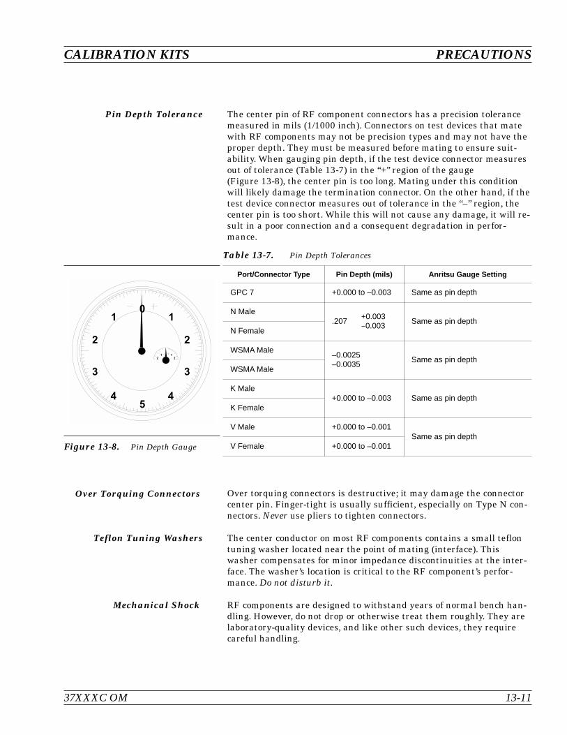
Pin Depth Tolerance The center pin of RF component connectors has a precision tolerancemeasured in mils (1/1000 inch). Connectors on test devices that matewith RF components may not be precision types and may not have theproper depth. They must be measured before mating to ensure suit-ability. When gauging pin depth, if the test device connector measuresout of tolerance (Table 13-7) in the “+” region of the gauge(Figure 13-8), the center pin is too long. Mating under this conditionwill likely damage the termination connector. On the other hand, if thetest device connector measures out of tolerance in the “–” region, thecenter pin is too short. While this will not cause any damage, it will re-sult in a poor connection and a consequent degradation in perfor-mance.
Over Torquing Connectors Over torquing connectors is destructive; it may damage the connectorcenter pin. Finger-tight is usually sufficient, especially on Type N con-nectors. Never use pliers to tighten connectors.
Teflon Tuning Washers The center conductor on most RF components contains a small teflontuning washer located near the point of mating (interface). Thiswasher compensates for minor impedance discontinuities at the inter-face. The washer’s location is critical to the RF component’s perfor-mance. Do not disturb it.
Mechanical Shock RF components are designed to withstand years of normal bench han-dling. However, do not drop or otherwise treat them roughly. They arelaboratory-quality devices, and like other such devices, they requirecareful handling.
37XXXC OM 13-11
CALIBRATION KITS PRECAUTIONS
Port/Connector Type Pin Depth (mils) Anritsu Gauge Setting
GPC 7 +0.000 to –0.003 Same as pin depth
N Male.207
+0.0030.003
Same as pin depthN Female
WSMA Male–0.0025–0.0035
Same as pin depthWSMA Male
K Male+0.000 to –0.003 Same as pin depth
K Female
V Male +0.000 to –0.001Same as pin depth
V Female +0.000 to –0.001
Table 13-7. Pin Depth Tolerances
01
2
3
45
1
2
3
4
21 1
2
Figure 13-8. Pin Depth Gauge

13-5 CLEANINGINSTRUCTIONS
Connector interfaces—especially the outer conductors on the GPC 7and SMA connectors—should be kept clean and free of dirt and otherdebris.
Denatured alcohol applied with a cotton swab applicator is recom-mended for cleaning connector interfaces.
NOTEMost cotton swabs are too large to fit in the smaller con-nector types. It is necessary to remove most of the cottonand then twist the remaining cotton tight. Be sure that theremaining cotton does not get stuck in the connector.
The following are some important tips on cleaning connectors:
Use only denatured alcohol as a solvent
Always use an appropriate size of cotton swab
Gently move the cotton swab around the center conductor
Never put lateral pressure on the connector’s center pin
Verify that no cotton or other foreign material remains in theconnector after cleaning
Only dampen the cotton swab. Do NOT saturate it
Compressed air can be used to remove foreign particles and todry the connector
Verify that the center pin has not been bent or damaged
Figure 13-9, following page, illustrates how to clean connectors.
CLEANING INSTRUCTIONS CALIBRATION KITS
13-12 37XXXC OM
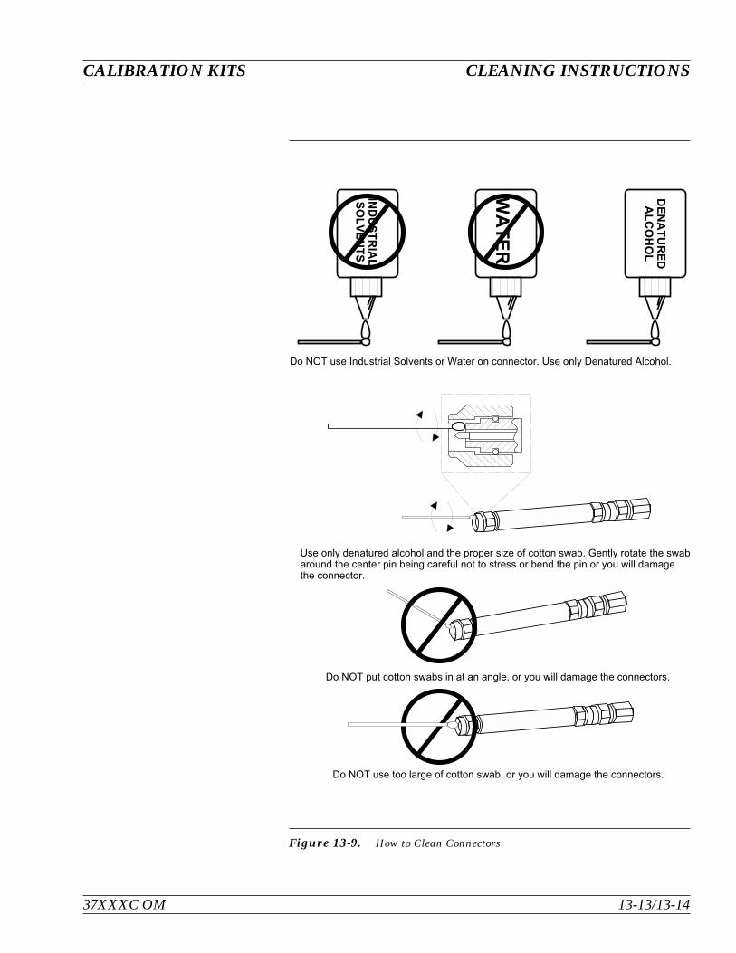
37XXXC OM 13-13/13-14
CALIBRATION KITS CLEANING INSTRUCTIONS
# J J 1 K J % . J # I .
J I I J 1 ; N J Z . ' I J Z I 1 1 0 N J J J I 1 Z 1 < 0 I .
# J Z J 1 0 5 Z 1 < 0 I J .
# J 0 N J Z 5 Z 1 < 0 I J .
Figure 13-9. How to Clean Connectors

Table of Contents
14-1 INTRODUCTION. . . . . . . . . . . . . . . . . . . . . . . . . . . . . . . . . . . 14-3
14-2 DESCRIPTION . . . . . . . . . . . . . . . . . . . . . . . . . . . . . . . . . . . . 14-3
14-3 PERFORMANCE SPECIFICATIONS . . . . . . . . . . . . . . . . . . . . . . . . 14-4
System Performance . . . . . . . . . . . . . . . . . . . . . . . . . . . . . . . . 14-4
Test Port Characteristics . . . . . . . . . . . . . . . . . . . . . . . . . . . . . 14-5
Measurement Capabilities . . . . . . . . . . . . . . . . . . . . . . . . . . . . 14-5
14-4 INSTALLATION . . . . . . . . . . . . . . . . . . . . . . . . . . . . . . . . . . . 14-6
14-5 CONTROLS AND CONNECTORS . . . . . . . . . . . . . . . . . . . . . . . . . 14-11
14-6 CALIBRATION . . . . . . . . . . . . . . . . . . . . . . . . . . . . . . . . . . . 14-13
14-7 OPERATION . . . . . . . . . . . . . . . . . . . . . . . . . . . . . . . . . . . . 14-14
Entering/ Leaving Millimeter Wave Operation . . . . . . . . . . . . . . . . . 14-14
Changing Bands/Modules While in Millimeter Wave. . . . . . . . . . . . . . 14-18
Allowable Millimeter Wave Module Configurations, Measurements andCalibrations. . . . . . . . . . . . . . . . . . . . . . . . . . . . . . . . . . . . 14-18
Effect of Default Program . . . . . . . . . . . . . . . . . . . . . . . . . . . . 14-19
Redefinition of Band Frequency Ranges . . . . . . . . . . . . . . . . . . . . 14-20
Use of Normal Multiple Source Mode . . . . . . . . . . . . . . . . . . . . . . 14-21
Stored Setups and Calibrations . . . . . . . . . . . . . . . . . . . . . . . . . 14-21
External Source and Power Levels . . . . . . . . . . . . . . . . . . . . . . . 14-22
14-8 MEASUREMENT PROCEDURE. . . . . . . . . . . . . . . . . . . . . . . . . . 14-23
14-9 REMOTE OPERATION. . . . . . . . . . . . . . . . . . . . . . . . . . . . . . . 14-24
14-10 OPERATIONAL CHECKOUT— GENERAL . . . . . . . . . . . . . . . . . . . 14-25
14-11 OPERATION CHECKOUT—IF POWER LEVEL TEST . . . . . . . . . . . . . 14-26
14-12 OPERATIONAL CHECKOUT— TRANSMISSION HIGH LEVEL NOISE TEST14-28
14-13 OPERATIONAL CHECKOUT— REFLECTION HIGH LEVEL NOISE TEST . 14-30
Chapter 14Millimeter WaveSystem


Chapter 14Millimeter Wave System
14-1 INTRODUCTION This chapter describes the 371XXC Millimeter Wave System, its opera-tion, and its measurement capabilities. For information on ME7808ABroadband System, refer to Chapter 15.
14-2 DESCRIPTION The 371XXC Millimeter Wave System (371XXCmm) consists of a37147C or 37169C VNA, two 680XXCor MG369XA Frequency Synthe-sizers, and a 3735B Millimeter Test Set having two 374X MillimeterWave Modules. There are 14 different 374X modules available (below)to accommodate different measurement types and frequency ranges.
3741A-Q 33 to 50 GHz Transmission Module
3741A-V 50 to 75 GHz Transmission Module
3741A-E 60 to 90 GHz Transmission Module
3741A-EE56 to 94 GHz Transmission Module
3741A-W 75 to 110 GHz Transmission Module
3741A-EW 65 to 110 GHz Transmission Module
3741A-F 90 to 140 GHz Transmission Module
3740A-Q 33 to 50 GHz Transmission/Reflection Module
3740A-V 50 to 75 GHz Transmission/Reflection Module
3740A-E 60 to 90 GHz Transmission/Reflection Module
3740A-EE 56 to 94 GHz Transmission/Reflection Module
3740A-W 75 to 110 GHz Transmission/Reflection Module
3740A-EW 65 to 110 GHz Transmission/Reflection Module
3740A-F 90 to 140 GHz Transmission/Reflection Module
37XXXC OM 14-3
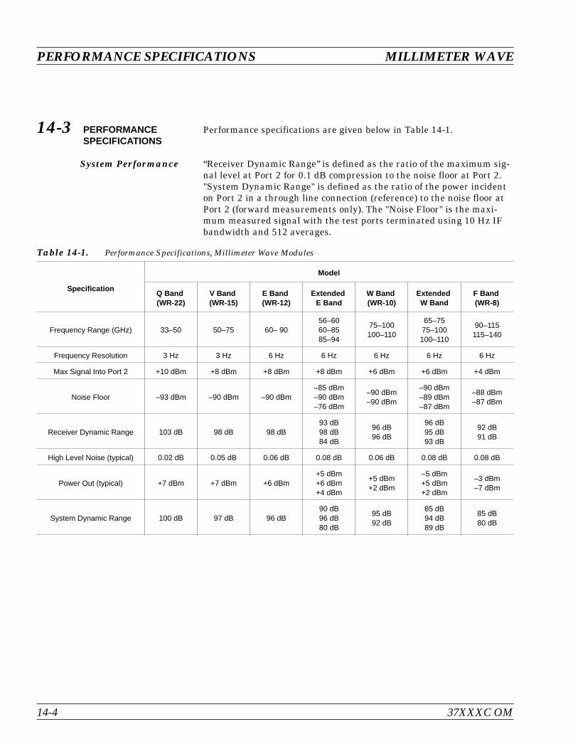
14-3 PERFORMANCESPECIFICATIONS
Performance specifications are given below in Table 14-1.
System Performance “Receiver Dynamic Range” is defined as the ratio of the maximum sig-nal level at Port 2 for 0.1 dB compression to the noise floor at Port 2."System Dynamic Range" is defined as the ratio of the power incidenton Port 2 in a through line connection (reference) to the noise floor atPort 2 (forward measurements only). The "Noise Floor" is the maxi-mum measured signal with the test ports terminated using 10 Hz IFbandwidth and 512 averages.
PERFORMANCE SPECIFICATIONS MILLIMETER WAVE
14-4 37XXXC OM
Specification
Model
Q Band(WR-22)
V Band(WR-15)
E Band(WR-12)
ExtendedE Band
W Band(WR-10)
ExtendedW Band
F Band(WR-8)
Frequency Range (GHz) 33–50 50–75 60– 9056–6060–8585–94
75–100100–110
65–7575–100100–110
90–115115–140
Frequency Resolution 3 Hz 3 Hz 6 Hz 6 Hz 6 Hz 6 Hz 6 Hz
Max Signal Into Port 2 +10 dBm +8 dBm +8 dBm +8 dBm +6 dBm +6 dBm +4 dBm
Noise Floor –93 dBm –90 dBm –90 dBm–85 dBm–90 dBm–76 dBm
–90 dBm–90 dBm
–90 dBm–89 dBm–87 dBm
–88 dBm–87 dBm
Receiver Dynamic Range 103 dB 98 dB 98 dB93 dB98 dB84 dB
96 dB96 dB
96 dB95 dB93 dB
92 dB91 dB
High Level Noise (typical) 0.02 dB 0.05 dB 0.06 dB 0.08 dB 0.06 dB 0.08 dB 0.08 dB
Power Out (typical) +7 dBm +7 dBm +6 dBm+5 dBm+6 dBm+4 dBm
+5 dBm+2 dBm
–5 dBm+5 dBm+2 dBm
–3 dBm–7 dBm
System Dynamic Range 100 dB 97 dB 96 dB90 dB96 dB80 dB
95 dB92 dB
85 dB94 dB89 dB
85 dB80 dB
Table 14-1. Performance Specifications, Millimeter Wave Modules
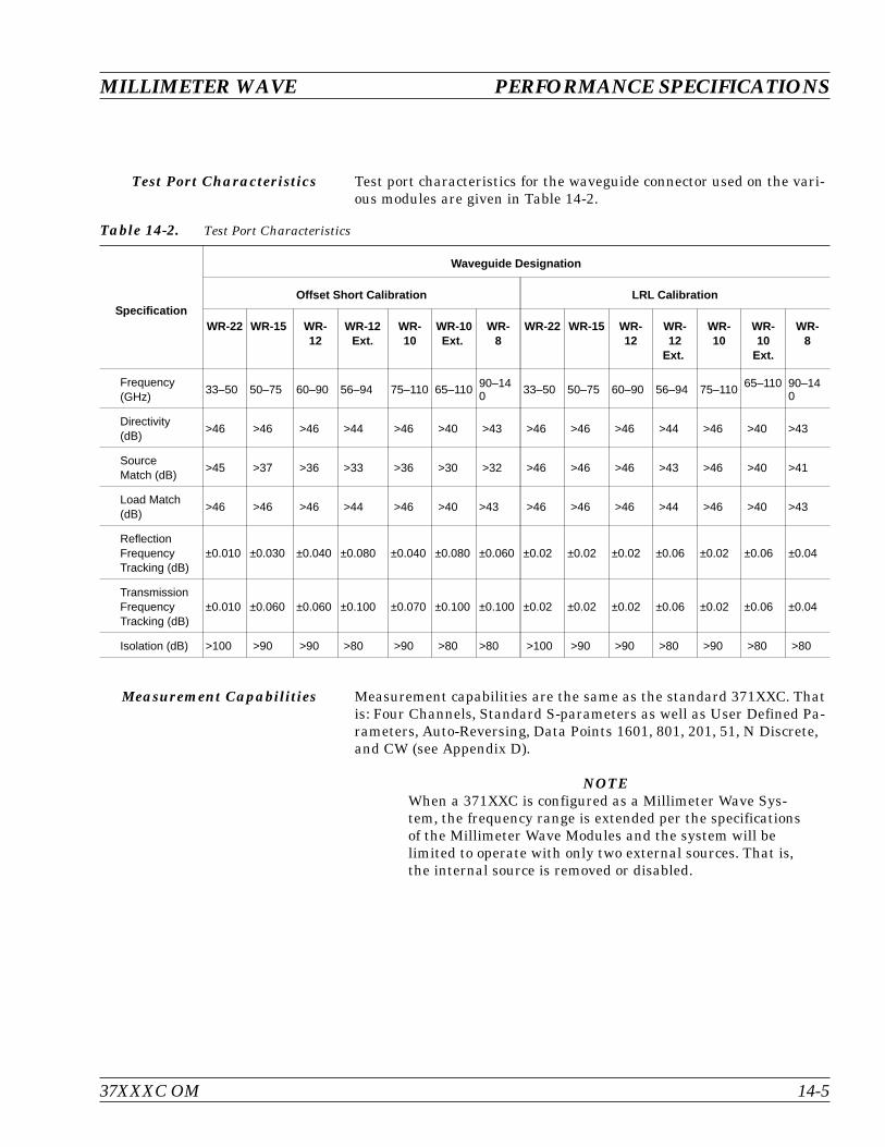
Test Port Characteristics Test port characteristics for the waveguide connector used on the vari-ous modules are given in Table 14-2.
Measurement Capabilities Measurement capabilities are the same as the standard 371XXC. Thatis: Four Channels, Standard S-parameters as well as User Defined Pa-rameters, Auto-Reversing, Data Points 1601, 801, 201, 51, N Discrete,and CW (see Appendix D).
NOTEWhen a 371XXC is configured as a Millimeter Wave Sys-tem, the frequency range is extended per the specificationsof the Millimeter Wave Modules and the system will belimited to operate with only two external sources. That is,the internal source is removed or disabled.
37XXXC OM 14-5
MILLIMETER WAVE PERFORMANCE SPECIFICATIONS
Specification
Waveguide Designation
Offset Short Calibration LRL Calibration
WR-22 WR-15 WR-12
WR-12Ext.
WR-10
WR-10Ext.
WR-8
WR-22 WR-15 WR-12
WR-12
Ext.
WR-10
WR-10
Ext.
WR-8
Frequency(GHz)
33–50 50–75 60–90 56–94 75–110 65–110 90–140 33–50 50–75 60–90 56–94 75–110 65–110 90–14
0
Directivity(dB)
>46 >46 >46 >44 >46 >40 >43 >46 >46 >46 >44 >46 >40 >43
SourceMatch (dB)
>45 >37 >36 >33 >36 >30 >32 >46 >46 >46 >43 >46 >40 >41
Load Match(dB)
>46 >46 >46 >44 >46 >40 >43 >46 >46 >46 >44 >46 >40 >43
ReflectionFrequencyTracking (dB)
±0.010 ±0.030 ±0.040 ±0.080 ±0.040 ±0.080 ±0.060 ±0.02 ±0.02 ±0.02 ±0.06 ±0.02 ±0.06 ±0.04
TransmissionFrequencyTracking (dB)
±0.010 ±0.060 ±0.060 ±0.100 ±0.070 ±0.100 ±0.100 ±0.02 ±0.02 ±0.02 ±0.06 ±0.02 ±0.06 ±0.04
Isolation (dB) >100 >90 >90 >80 >90 >80 >80 >100 >90 >90 >80 >90 >80 >80
Table 14-2. Test Port Characteristics
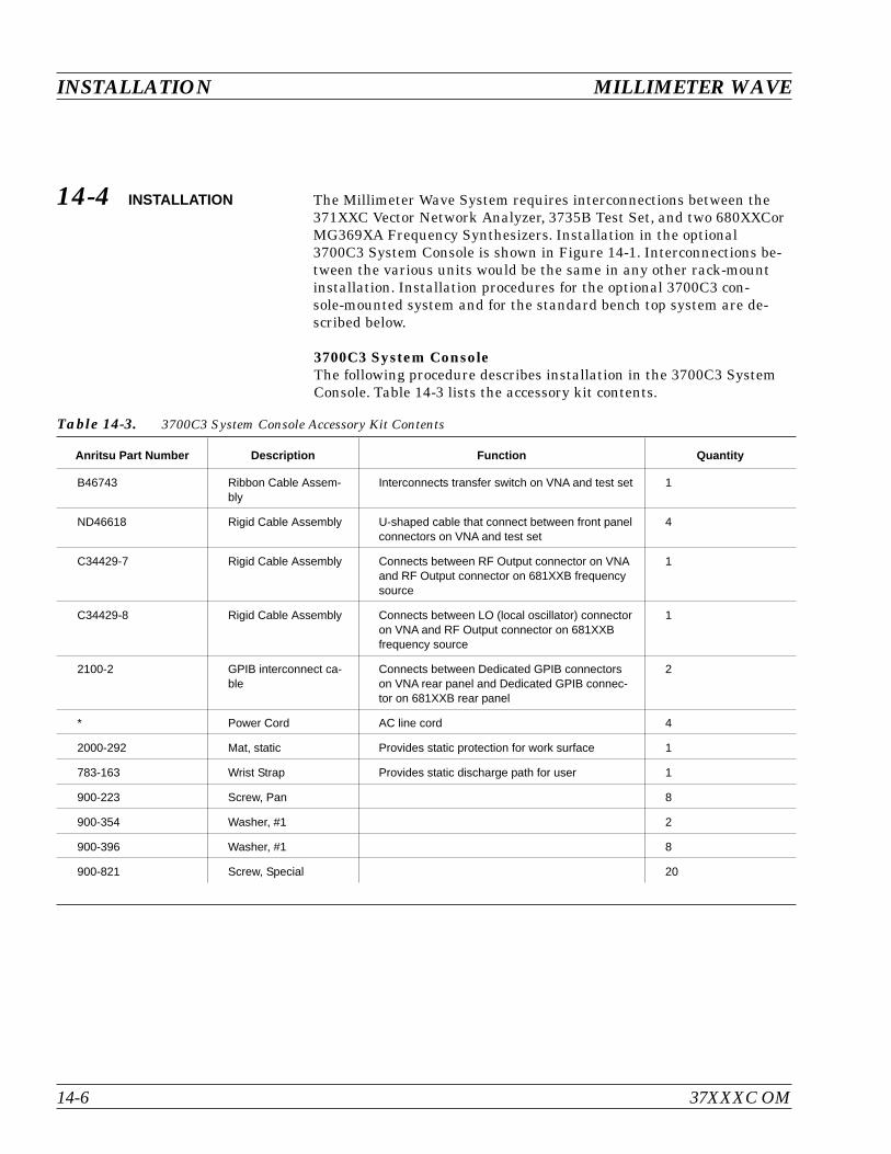
14-4 INSTALLATION The Millimeter Wave System requires interconnections between the371XXC Vector Network Analyzer, 3735B Test Set, and two 680XXCorMG369XA Frequency Synthesizers. Installation in the optional3700C3 System Console is shown in Figure 14-1. Interconnections be-tween the various units would be the same in any other rack-mountinstallation. Installation procedures for the optional 3700C3 con-sole-mounted system and for the standard bench top system are de-scribed below.
3700C3 System ConsoleThe following procedure describes installation in the 3700C3 SystemConsole. Table 14-3 lists the accessory kit contents.
INSTALLATION MILLIMETER WAVE
14-6 37XXXC OM
Anritsu Part Number Description Function Quantity
B46743 Ribbon Cable Assem-bly
Interconnects transfer switch on VNA and test set 1
ND46618 Rigid Cable Assembly U-shaped cable that connect between front panelconnectors on VNA and test set
4
C34429-7 Rigid Cable Assembly Connects between RF Output connector on VNAand RF Output connector on 681XXB frequencysource
1
C34429-8 Rigid Cable Assembly Connects between LO (local oscillator) connectoron VNA and RF Output connector on 681XXBfrequency source
1
2100-2 GPIB interconnect ca-ble
Connects between Dedicated GPIB connectorson VNA rear panel and Dedicated GPIB connec-tor on 681XXB rear panel
2
* Power Cord AC line cord 4
2000-292 Mat, static Provides static protection for work surface 1
783-163 Wrist Strap Provides static discharge path for user 1
900-223 Screw, Pan 8
900-354 Washer, #1 2
900-396 Washer, #1 8
900-821 Screw, Special 20
Table 14-3. 3700C3 System Console Accessory Kit Contents
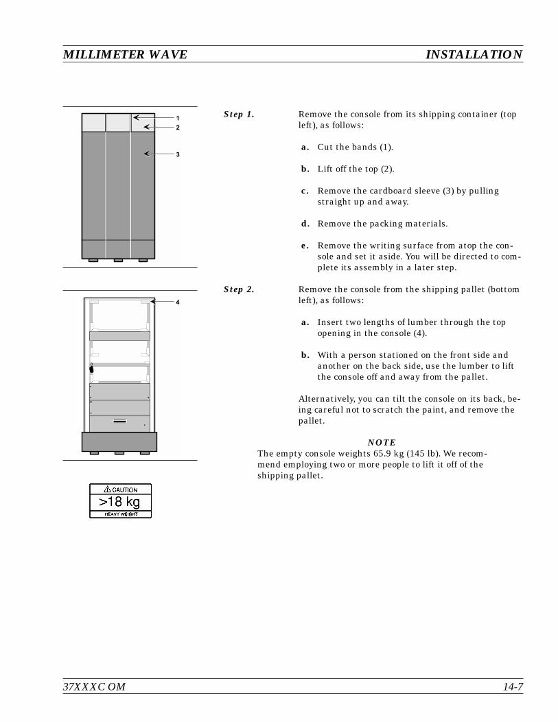
Step 1. Remove the console from its shipping container (topleft), as follows:
a. Cut the bands (1).
b. Lift off the top (2).
c. Remove the cardboard sleeve (3) by pullingstraight up and away.
d. Remove the packing materials.
e. Remove the writing surface from atop the con-sole and set it aside. You will be directed to com-plete its assembly in a later step.
Step 2. Remove the console from the shipping pallet (bottomleft), as follows:
a. Insert two lengths of lumber through the topopening in the console (4).
b. With a person stationed on the front side andanother on the back side, use the lumber to liftthe console off and away from the pallet.
Alternatively, you can tilt the console on its back, be-ing careful not to scratch the paint, and remove thepallet.
NOTEThe empty console weights 65.9 kg (145 lb). We recom-mend employing two or more people to lift it off of theshipping pallet.
37XXXC OM 14-7
MILLIMETER WAVE INSTALLATION
#
"

Step 3. Prepare the front of the console (top left) for installa-tion of the equipment, as follows:
Cut the tie wrap from the Wrist Strap/Table Matground port (6), bring it out through the openingabove panel (7), and let it hang free and out of theway.
Step 4. Prepare the rear of the console (bottom left) for in-stallation of the equipment, as follows:
a. Open the rear door, cut the tie wraps from thewriting-surface rails (8), and remove the railsfrom the console.
b. Cut the tie wrap from the Line Cord (9), and un-coil the cord.
Step 5. Prepare the Writing Surface by attaching the tworails as shown below, using the 10-32 x 1-inch screwsand #10 split-lock washers supplied in the attach-ing-parts kit.
NOTEIn the next step, install the 680XXC that containsOption 15 (High Power Option) as the top Source. ForWR-8 F-Band installation, the bottom Source is the68067C or MG369XA with Option 15.
Step 6. Install the 371XXC VNA, 3735B Test Set, and two680XXCor MG369XA Frequency Synthesizers in theconsole, as shown in Figure 14-1. Secure with screws900-821 (Table 14-3).
INSTALLATION MILLIMETER WAVE
14-8 37XXXC OM
7 8 : L $ "Q 7 % " Q 7 % "
7 8 : L $ "Q 7 % "
6
7
:
A
Step 7. From the rear, connect cables as described below (seeFigure 14-1 for illustration):
a. Ribbon cable between Transfer Switch connec-tors on VNA and test set
b. 2100-2 cable between Dedicated GPIB on VNAand Dedicated GPIB on frequency source #1(top)
c. 2100-2 between Dedicated GPIB on VNA andDedicated GPIB on frequency source #2 (bottom)
d. From the front, connect the four U-shapedsemirigid cables (ND46618) between connectorb1, a1, a2, and b2 on VNA and test set
e. Connect cable ND46620 between RF Input onVNA and RF Output on 680XXCor MG369XA #2(bottom source)
f. Connect cable ND46621 between the LO Inputon the VNA and the RF Output on the680XXCor MG369XA #1 (top source)
Step 8. Secure the Writing Surface rails to the tapped holein each rail guide. Use two 10-32x1/2-inch screws,two #10 split-lock washers, and two #10 flat washersfrom the attaching parts kit.
Step 9. Install the static mat on the work surface and con-nect the wrist strap.
Step 10. Lay the appropriate Transmission/Reflection Module(3740 Series), or Transmission Only Module(3741 Series), or one of each, on the work surfacewith the test port connectors facing each other.
NOTEThe system will function with a single Transmission/Re-flection Module, and it can be connected to either Port 1Module or Port 2 Module connector pad. The normal con-figuration, however, uses a Transmission/Reflection Mod-ule connected to the Port 1 Module connector pad and aTransmission Only Module connected to the Port 2 Moduleconnector pad.
37XXXC OM 14-9
MILLIMETER WAVE INSTALLATION
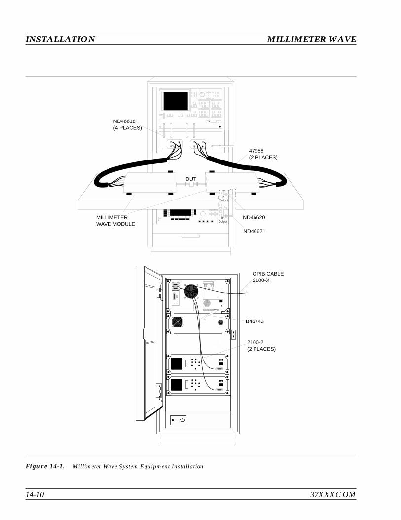
INSTALLATION MILLIMETER WAVE
14-10 37XXXC OM
Figure 14-1. Millimeter Wave System Equipment Installation
RFOutput
RFOutput
47958(2 PLACES)
ND46618(4 PLACES)
DUT
MILLIMETERWAVE MODULE
ND46620
ND46621
GPIB CABLE2100-X
B46743
2100-2(2 PLACES)

Step 11. Place one of the grey cable harnesses between thePort 1 Module connector pad and the Transmis-sion/Reflection Module. Connect the named connec-tors on each end with their like-named counterpartson the module and the test set.
Step 12. Place the other grey cable harness between thePort 2 Module connector pad and the TransmissionOnly Module. Connect the named connectors on eachend with their like-named counterparts on the mod-ule and the test set.
Bench Top SystemThe following procedure describes how to arrange and interconnect thesystem instruments in a benchtop configuration.
Step 13. Arrange the instruments in a stack as they are inthe console; that is, from top to bottom: VNA, testset, source #1, source #2.
Step 14. Interconnect the instruments as described in Step 3of the 3700C3 procedure.
Step 15. Interconnect the module(s) as described in Steps 9through 11 of the 3700C3 procedure.
14-5 CONTROLS ANDCONNECTORS
Figure 14-2 (following page) shows the front and rear panel connectorsand describes each one for the 3735B Test Set and 3740 and 3741Modules.
37XXXC OM 14-11
MILLIMETER WAVE CONTROLS AND CONNECTORS
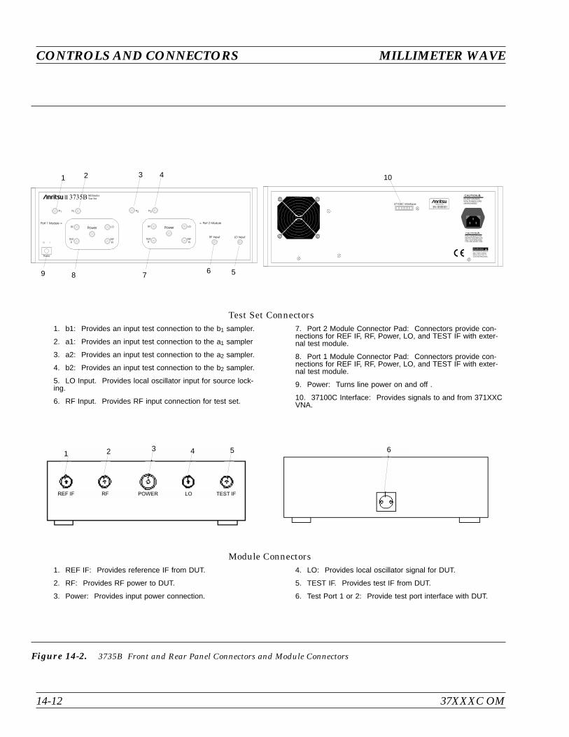
CONTROLS AND CONNECTORS MILLIMETER WAVE
14-12 37XXXC OM
Figure 14-2. 3735B Front and Rear Panel Connectors and Module Connectors
1. REF IF: Provides reference IF from DUT.
2. RF: Provides RF power to DUT.
3. Power: Provides input power connection.
4. LO: Provides local oscillator signal for DUT.
5. TEST IF. Provides test IF from DUT.
6. Test Port 1 or 2: Provide test port interface with DUT.
Module Connectors
1. b1: Provides an input test connection to the b1 sampler.
2. a1: Provides an input test connection to the a1 sampler
3. a2: Provides an input test connection to the a2 sampler.
4. b2: Provides an input test connection to the b2 sampler.
5. LO Input. Provides local oscillator input for source lock-ing.
6. RF Input. Provides RF input connection for test set.
7. Port 2 Module Connector Pad: Connectors provide con-nections for REF IF, RF, Power, LO, and TEST IF with exter-nal test module.
8. Port 1 Module Connector Pad: Connectors provide con-nections for REF IF, RF, Power, LO, and TEST IF with exter-nal test module.
9. Power: Turns line power on and off .
10. 37100C Interface: Provides signals to and from 371XXCVNA.
Test Set Connectors
Power
Port 1 Module Port 2 Module
RF Input LO Input
b1
RF RF
TESTIF
TESTIF
REFIN
REFIN
Power PowerLO LO
a2a1 b2
3735BMillimiter
Test Set
1
9
2 3 4
8 76 5
WARNINGNO OPERATOR SERVICE-
ABLE PARTS INSIDE
REFER SERVICING TO
QUALIFIED PERSONNEL
CAUTION
CAUTION
FOR CONTINUED FIRE
DO NOT OPERATE
WITH POWER CORDUNGROUNDED
PROTECTION REPLACE
ONLY WITH SPECIFIEDTYPE AND RATED FUSE
MADE IN USA
SN 00000137100C Interface
10
REF IF RF POWER LO TEST IF
1 2 543 6
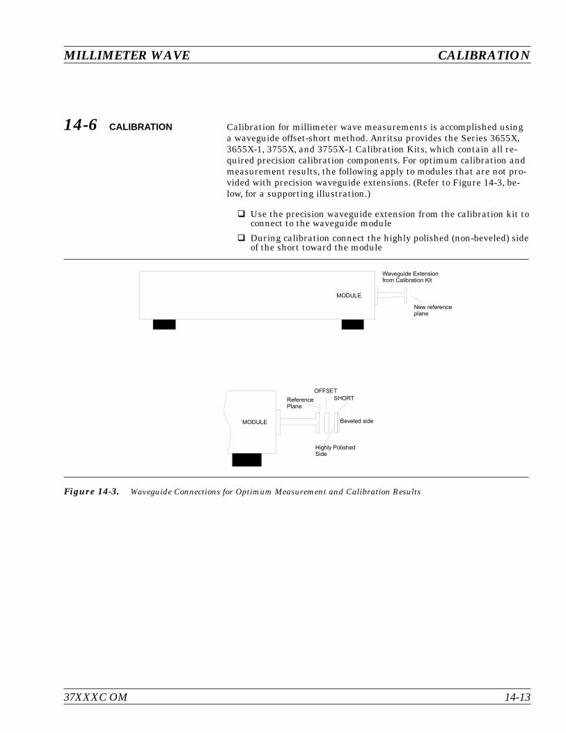
14-6 CALIBRATION Calibration for millimeter wave measurements is accomplished usinga waveguide offset-short method. Anritsu provides the Series 3655X,3655X-1, 3755X, and 3755X-1 Calibration Kits, which contain all re-quired precision calibration components. For optimum calibration andmeasurement results, the following apply to modules that are not pro-vided with precision waveguide extensions. (Refer to Figure 14-3, be-low, for a supporting illustration.)
Use the precision waveguide extension from the calibration kit toconnect to the waveguide module
During calibration connect the highly polished (non-beveled) sideof the short toward the module
37XXXC OM 14-13
MILLIMETER WAVE CALIBRATION
Waveguide Extensionfrom Calibration Kit
New referenceplane
Beveled side
Highly PolishedSide
SHORT
OFFSET
ReferencePlane
MODULE
MODULE
Figure 14-3. Waveguide Connections for Optimum Measurement and Calibration Results
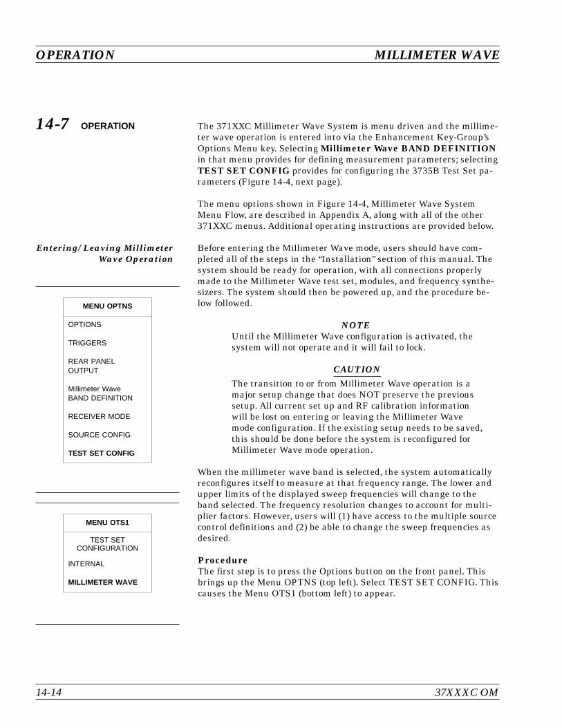
14-7 OPERATION The 371XXC Millimeter Wave System is menu driven and the millime-ter wave operation is entered into via the Enhancement Key-Group’sOptions Menu key. Selecting Millimeter Wave BAND DEFINITIONin that menu provides for defining measurement parameters; selectingTEST SET CONFIG provides for configuring the 3735B Test Set pa-rameters (Figure 14-4, next page).
The menu options shown in Figure 14-4, Millimeter Wave SystemMenu Flow, are described in Appendix A, along with all of the other371XXC menus. Additional operating instructions are provided below.
Entering/ Leaving MillimeterWave Operation
Before entering the Millimeter Wave mode, users should have com-pleted all of the steps in the “Installation” section of this manual. Thesystem should be ready for operation, with all connections properlymade to the Millimeter Wave test set, modules, and frequency synthe-sizers. The system should then be powered up, and the procedure be-low followed.
NOTEUntil the Millimeter Wave configuration is activated, thesystem will not operate and it will fail to lock.
CAUTIONThe transition to or from Millimeter Wave operation is amajor setup change that does NOT preserve the previoussetup. All current set up and RF calibration informationwill be lost on entering or leaving the Millimeter Wavemode configuration. If the existing setup needs to be saved,this should be done before the system is reconfigured forMillimeter Wave mode operation.
When the millimeter wave band is selected, the system automaticallyreconfigures itself to measure at that frequency range. The lower andupper limits of the displayed sweep frequencies will change to theband selected. The frequency resolution changes to account for multi-plier factors. However, users will (1) have access to the multiple sourcecontrol definitions and (2) be able to change the sweep frequencies asdesired.
ProcedureThe first step is to press the Options button on the front panel. Thisbrings up the Menu OPTNS (top left). Select TEST SET CONFIG. Thiscauses the Menu OTS1 (bottom left) to appear.
OPERATION MILLIMETER WAVE
14-14 37XXXC OM
MENU OPTNS
OPTIONS
TRIGGERS
REAR PANELOUTPUT
Millimeter WaveBAND DEFINITION
RECEIVER MODE
SOURCE CONFIG
TEST SET CONFIG
MENU OTS1
TEST SETCONFIGURATION
INTERNAL
MILLIMETER WAVE

37XXXC OM 14-15
MILLIMETER WAVE OPERATION
OptionMenu
MENU OPTNS
REAR PANELOUTPUT
DIAGNOSTICS
MILLIMETER WAVEBAND DEFINITION
PLOT OPTIONS
OPTIONS
RECEIVER MODE
TO SELECTPRESS <ENTER>
SOURCE CONFIG
TEST SET CONFIG MENU MMW4
BAND START FREQXX.XXXXXX
Mm WAVE BAND
RECEIVERSOURCE 2SOURCE 1
C.W. ON/OFF
MULTIPLIER
XXX
DIVISOR
XXX
OFFSET FREQ
XXXXXXXX
DEFAULT EQUATIONS
ACCEPT EQUATIONS
EQUATION TO EDIT
EQUATION SUMMARY
XX.XXXXXXBAND STOP FREQ
MENU MMW1
MENU MMW2
MILLIMETER WAVETEST SET BAND
MILLIMETER WAVETEST SET MODULES
WR-22
(33 - 50 GHz)
PORT 1 MODULE
3740/3741/NONE
PORT 1 MODULE
3740/3741/NONE
WR-15
(50 - 75 GHz)
PORT 2 MODULE
3740/3741/NONE
PORT 2 MODULE
3740/3741/NONE
ACCEPT CONFIG
WR-12
(60 - 90 GHz)
WR-10
(75 - 110 GHz)
(56 - 94 GHz)
WR-12 EXTENDED
(65 - 110 GHz)
WR-10 EXTENDED
90- 140 GHz)
WR-8
MENU OTS1
INTERNAL
MILLIMETER WAVE
TEST SETCONFIGURATION
PRESS <ENTER>TO SELECT
MENU OTS2
MENU MMW3
WARNING
CONTINUINGWILL INVALIDATE
CURRENTSETUP AND
CALIBRATION
WARNING
CONTINUINGWILL INVALIDATE
CURRENTSETUP AND
CALIBRATION
TEST SETCONFIGURATION
TEST SETCONFIGURATION
mm WAVE BAND:XXXXXXXXXX
TO SELECT
TO SELECT
PRESS <ENTER>
PRESS <ENTER>
PRESS <ENTER>TO SELECT
PRESS <ENTER>TO SELECT
PRESS <CLEAR>TO ABORT
PRESS <CLEAR>TO ABORT
TO MENU SU1/SU2
Figure 14-4. Millimeter Wave System Menu Flow
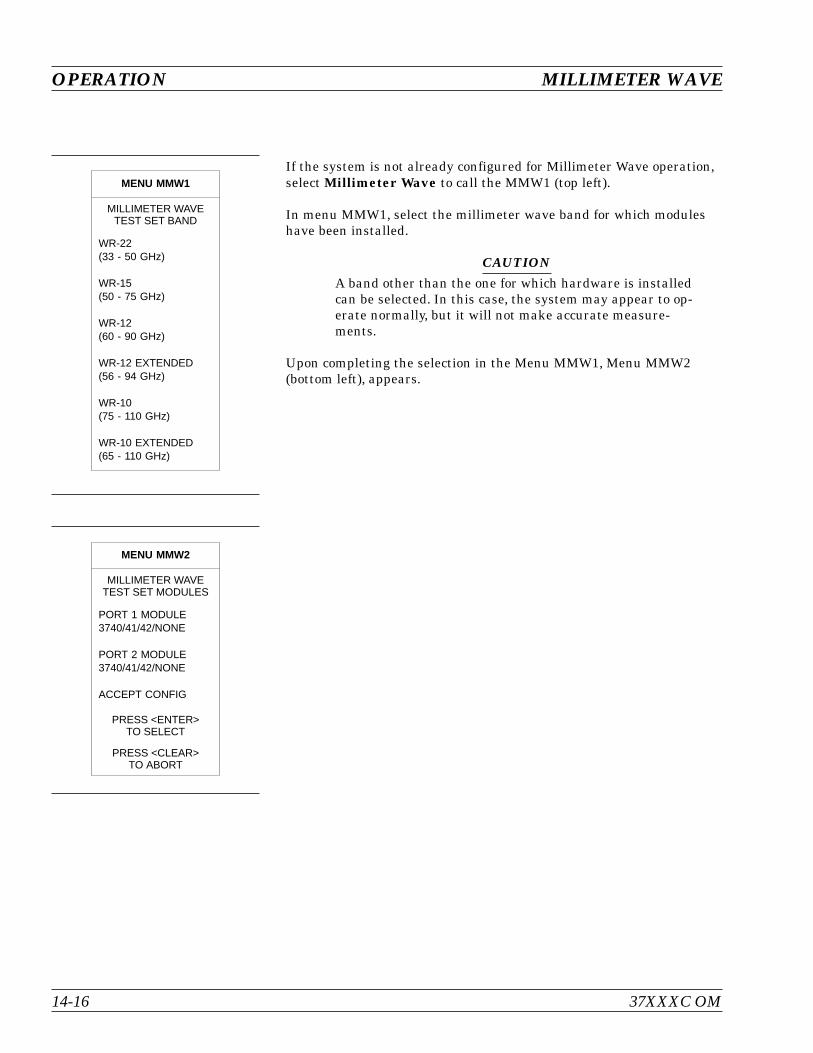
If the system is not already configured for Millimeter Wave operation,select Millimeter Wave to call the MMW1 (top left).
In menu MMW1, select the millimeter wave band for which moduleshave been installed.
CAUTIONA band other than the one for which hardware is installedcan be selected. In this case, the system may appear to op-erate normally, but it will not make accurate measure-ments.
Upon completing the selection in the Menu MMW1, Menu MMW2(bottom left), appears.
OPERATION MILLIMETER WAVE
14-16 37XXXC OM
MENU MMW2
MILLIMETER WAVETEST SET MODULES
PORT 1 MODULE3740/41/42/NONE
PORT 2 MODULE3740/41/42/NONE
ACCEPT CONFIG
PRESS <ENTER>TO SELECT
PRESS <CLEAR>TO ABORT
MENU MMW1
MILLIMETER WAVETEST SET BAND
WR-22(33 - 50 GHz)
WR-15(50 - 75 GHz)
WR-12(60 - 90 GHz)
WR-12 EXTENDED(56 - 94 GHz)
WR-10(75 - 110 GHz)
WR-10 EXTENDED(65 - 110 GHz)
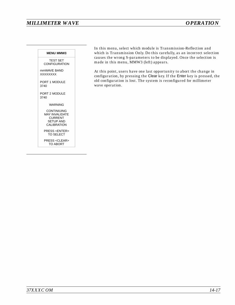
In this menu, select which module is Transmission-Reflection andwhich is Transmission Only. Do this carefully, as an incorrect selectioncauses the wrong S-parameters to be displayed. Once the selection ismade in this menu, MMW3 (left) appears.
At this point, users have one last opportunity to abort the change inconfiguration, by pressing the Clear key. If the Enter key is pressed, theold configuration is lost. The system is reconfigured for millimeterwave operation.
37XXXC OM 14-17
MILLIMETER WAVE OPERATION
MENU MMW3
TEST SETCONFIGURATION
mmWAVE BANDXXXXXXXX
PORT 1 MODULE3740
PORT 2 MODULE3740
WARNING
CONTINIUINGMAY INVALIDATE
CURRENTSETUP AND
CALIBRATION
PRESS <ENTER>TO SELECT
PRESS <CLEAR>TO ABORT
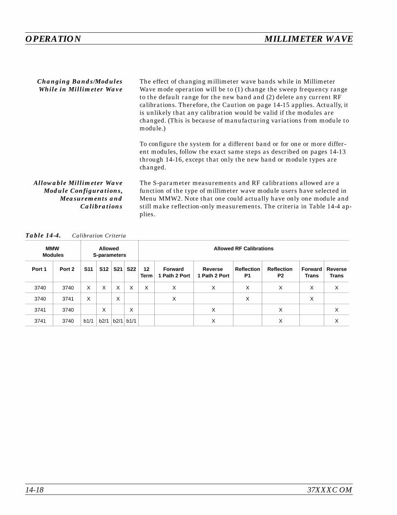
Changing Bands/ModulesWhile in Millimeter Wave
The effect of changing millimeter wave bands while in MillimeterWave mode operation will be to (1) change the sweep frequency rangeto the default range for the new band and (2) delete any current RFcalibrations. Therefore, the Caution on page 14-15 applies. Actually, itis unlikely that any calibration would be valid if the modules arechanged. (This is because of manufacturing variations from module tomodule.)
To configure the system for a different band or for one or more differ-ent modules, follow the exact same steps as described on pages 14-13through 14-16, except that only the new band or module types arechanged.
Allowable Millimeter WaveModule Configurations,
Measurements andCalibrations
The S-parameter measurements and RF calibrations allowed are afunction of the type of millimeter wave module users have selected inMenu MMW2. Note that one could actually have only one module andstill make reflection-only measurements. The criteria in Table 14-4 ap-plies.
OPERATION MILLIMETER WAVE
14-18 37XXXC OM
MMWModules
AllowedS-parameters
Allowed RF Calibrations
Port 1 Port 2 S11 S12 S21 S22 12Term
Forward1 Path 2 Port
Reverse1 Path 2 Port
ReflectionP1
ReflectionP2
ForwardTrans
ReverseTrans
3740 3740 X X X X X X X X X X X
3740 3741 X X X X X
3741 3740 X X X X X
3741 3740 b1/1 b2/1 b2/1 b1/1 X X X
Table 14-4. Calibration Criteria
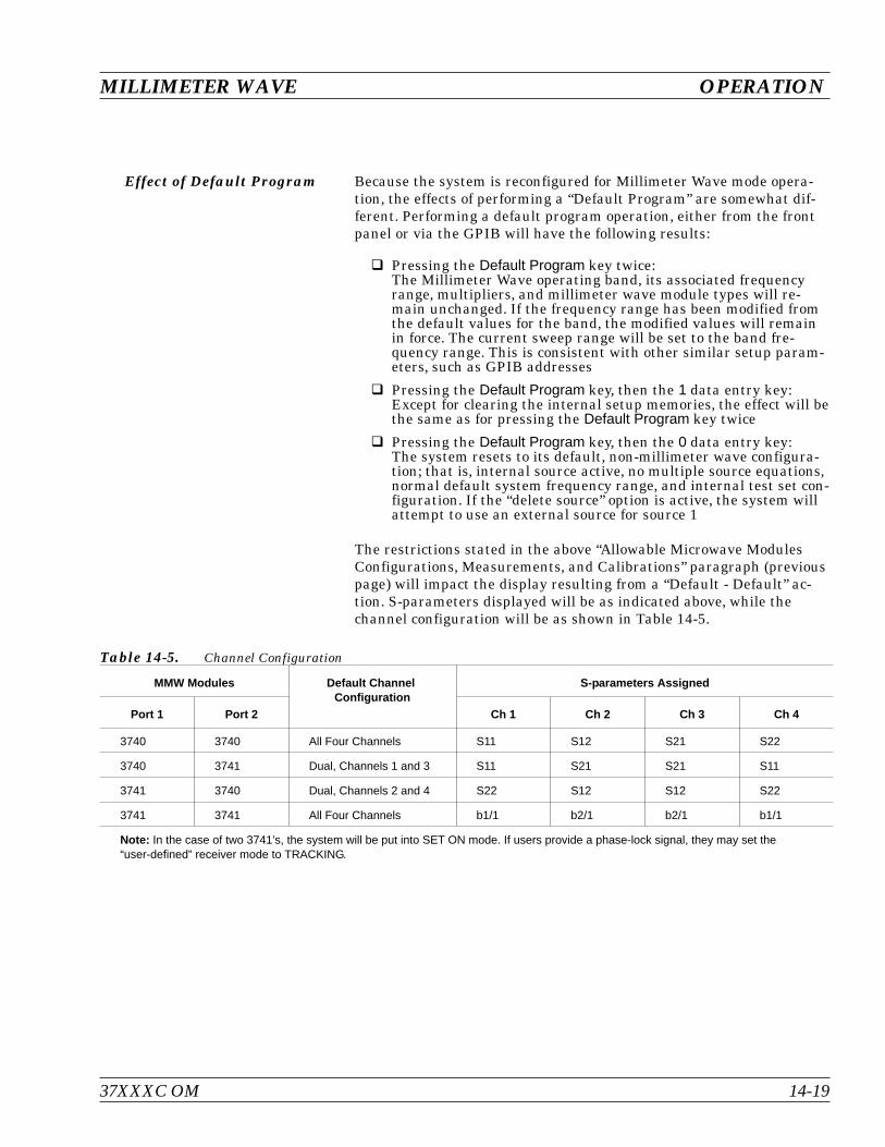
Effect of Default Program Because the system is reconfigured for Millimeter Wave mode opera-tion, the effects of performing a “Default Program” are somewhat dif-ferent. Performing a default program operation, either from the frontpanel or via the GPIB will have the following results:
Pressing the Default Program key twice:The Millimeter Wave operating band, its associated frequencyrange, multipliers, and millimeter wave module types will re-main unchanged. If the frequency range has been modified fromthe default values for the band, the modified values will remainin force. The current sweep range will be set to the band fre-quency range. This is consistent with other similar setup param-eters, such as GPIB addresses
Pressing the Default Program key, then the 1 data entry key:Except for clearing the internal setup memories, the effect will bethe same as for pressing the Default Program key twice
Pressing the Default Program key, then the 0 data entry key:The system resets to its default, non-millimeter wave configura-tion; that is, internal source active, no multiple source equations,normal default system frequency range, and internal test set con-figuration. If the “delete source” option is active, the system willattempt to use an external source for source 1
The restrictions stated in the above “Allowable Microwave ModulesConfigurations, Measurements, and Calibrations” paragraph (previouspage) will impact the display resulting from a “Default - Default” ac-tion. S-parameters displayed will be as indicated above, while thechannel configuration will be as shown in Table 14-5.
37XXXC OM 14-19
MILLIMETER WAVE OPERATION
MMW Modules Default ChannelConfiguration
S-parameters Assigned
Port 1 Port 2 Ch 1 Ch 2 Ch 3 Ch 4
3740 3740 All Four Channels S11 S12 S21 S22
3740 3741 Dual, Channels 1 and 3 S11 S21 S21 S11
3741 3740 Dual, Channels 2 and 4 S22 S12 S12 S22
3741 3741 All Four Channels b1/1 b2/1 b2/1 b1/1
Note: In the case of two 3741’s, the system will be put into SET ON mode. If users provide a phase-lock signal, they may set the“user-defined” receiver mode to TRACKING.
Table 14-5. Channel Configuration
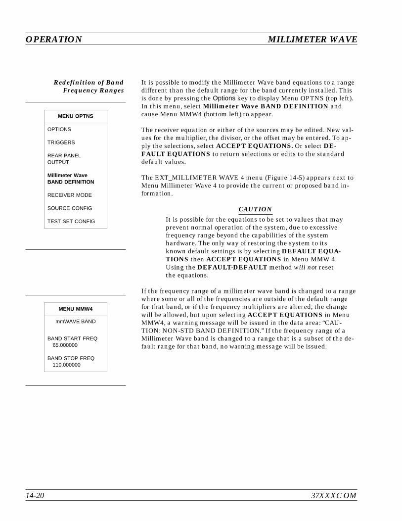
Redefinition of BandFrequency Ranges
It is possible to modify the Millimeter Wave band equations to a rangedifferent than the default range for the band currently installed. Thisis done by pressing the Options key to display Menu OPTNS (top left).In this menu, select Millimeter Wave BAND DEFINITION andcause Menu MMW4 (bottom left) to appear.
The receiver equation or either of the sources may be edited. New val-ues for the multiplier, the divisor, or the offset may be entered. To ap-ply the selections, select ACCEPT EQUATIONS. Or select DE-FAULT EQUATIONS to return selections or edits to the standarddefault values.
The EXT_MILLIMETER WAVE 4 menu (Figure 14-5) appears next toMenu Millimeter Wave 4 to provide the current or proposed band in-formation.
CAUTIONIt is possible for the equations to be set to values that mayprevent normal operation of the system, due to excessivefrequency range beyond the capabilities of the systemhardware. The only way of restoring the system to itsknown default settings is by selecting DEFAULT EQUA-TIONS then ACCEPT EQUATIONS in Menu MMW 4.Using the DEFAULT-DEFAULT method will not resetthe equations.
If the frequency range of a millimeter wave band is changed to a rangewhere some or all of the frequencies are outside of the default rangefor that band, or if the frequency multipliers are altered, the changewill be allowed, but upon selecting ACCEPT EQUATIONS in MenuMMW4, a warning message will be issued in the data area: “CAU-TION: NON-STD BAND DEFINITION.” If the frequency range of aMillimeter Wave band is changed to a range that is a subset of the de-fault range for that band, no warning message will be issued.
OPERATION MILLIMETER WAVE
14-20 37XXXC OM
MENU MMW4
mmWAVE BAND
BAND START FREQ65.000000
BAND STOP FREQ110.000000
MENU OPTNS
OPTIONS
TRIGGERS
REAR PANELOUTPUT
Millimeter WaveBAND DEFINITION
RECEIVER MODE
SOURCE CONFIG
TEST SET CONFIG
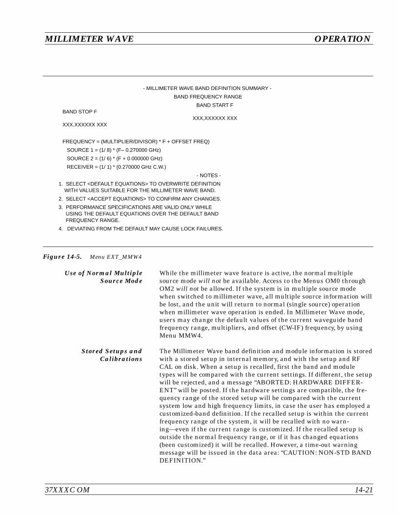
Use of Normal MultipleSource Mode
While the millimeter wave feature is active, the normal multiplesource mode will not be available. Access to the Menus OM0 throughOM2 will not be allowed. If the system is in multiple source modewhen switched to millimeter wave, all multiple source information willbe lost, and the unit will return to normal (single source) operationwhen millimeter wave operation is ended. In Millimeter Wave mode,users may change the default values of the current waveguide bandfrequency range, multipliers, and offset (CW-IF) frequency, by usingMenu MMW4.
Stored Setups andCalibrations
The Millimeter Wave band definition and module information is storedwith a stored setup in internal memory, and with the setup and RFCAL on disk. When a setup is recalled, first the band and moduletypes will be compared with the current settings. If different, the setupwill be rejected, and a message “ABORTED: HARDWARE DIFFER-ENT” will be posted. If the hardware settings are compatible, the fre-quency range of the stored setup will be compared with the currentsystem low and high frequency limits, in case the user has employed acustomized-band definition. If the recalled setup is within the currentfrequency range of the system, it will be recalled with no warn-ing—even if the current range is customized. If the recalled setup isoutside the normal frequency range, or if it has changed equations(been customized) it will be recalled. However, a time-out warningmessage will be issued in the data area: “CAUTION: NON-STD BANDDEFINITION.”
37XXXC OM 14-21
MILLIMETER WAVE OPERATION
- MILLIMETER WAVE BAND DEFINITION SUMMARY -
BAND FREQUENCY RANGE
BAND START FBAND STOP F
XXX,XXXXXX XXXXXX.XXXXXX XXX
FREQUENCY = (MULTIPLIER/DIVISOR) * F + OFFSET FREQ)
SOURCE 1 = (1/ 8) * (F– 0.270000 GHz)
SOURCE 2 = (1/ 6) * (F + 0.000000 GHz)
RECEIVER = (1/ 1) * (0.270000 GHz C.W.)
- NOTES -
1. SELECT <DEFAULT EQUATIONS> TO OVERWRITE DEFINITIONWITH VALUES SUITABLE FOR THE MILLIMETER WAVE BAND.
2. SELECT <ACCEPT EQUATIONS> TO CONFIRM ANY CHANGES.
3. PERFORMANCE SPECIFICATIONS ARE VALID ONLY WHILEUSING THE DEFAULT EQUATIONS OVER THE DEFAULT BANDFREQUENCY RANGE.
4. DEVIATING FROM THE DEFAULT MAY CAUSE LOCK FAILURES.
Figure 14-5. Menu EXT_MMW4

External Source and PowerLevels
When MILLIMETER WAVE has been selected in Menu OTS1, thesystem checks for the existence of two external sources. If eithersource is not connected and operating, a warning message is posted tothe screen. On entering Millimeter Wave mode operation, the systemwill automatically be configured to use the two external sources. TheMillimeter Wave mode will not function properly with lowsource-power levels. Therefore, on entering this mode the source-powerlevels will be adjusted to a predefined level. However the SourceConfig and Test Signals menus will still be available to users, tochange power settings and source configuration if so desired.
OPERATION MILLIMETER WAVE
14-22 37XXXC OM

14-8 MEASUREMENTPROCEDURE
The measurement of a Device Under Test (DUT) using the MillimeterWave mode is quite similar to one using a coaxial measurement tech-nique. However, due to the more complex nature of the MillimeterWave System equipment, additional care must be taken to ensure thateverything is set up properly. Depending upon the type of measure-ment being performed, the setup may vary. The following is a descrip-tion of a typical measurement procedure for a passive two-port DUT.
Step 1. Verify Correct Band DefinitionUse Menu MMW1 (top left) to examine the currentmillimeter wave band selection, and Menu MMW2(bottom left) to examine the current module selec-tions to be sure that they match the installed hard-ware. Examine MenuMMW4 (next page) to verifythat the band equations are set correctly. If there isany doubt whether the setting are correct, use theDEFAULT EQUATIONS selection to reset them.
Step 2. Verify Correct Setup for the SystemThe safest way to do this is to press the Default keytwice. This returns the system to the proper fre-quency range and power settings for the current mil-limeter wave hardware configuration. It is very im-portant that the RF sources be set to the correctpower levels. Set Source 1 (LO) to +17 dBm andSource 2 (RF) to +13 dBm.
Step 3. Perform and Verify an RF CalibrationThe system may now be calibrated using an appro-priate Anritsu Calibration Kit. Be sure to load thecalibration kit information from the provided floppydisk into the instrument first. The default calibra-tion type is Offset-Short, but an LRL/LRM calibra-tion may also be used. See Chapters 4 and 7 for helpwith RF Calibration details. Consult Table 14-4 forlimitations on which calibrations may be performedas a function of the module types installed.
Step 4. Attach the DUTUse the calibrated torque wrench provided with theCalibration Kit to tighten the waveguide flange re-taining screws on the DUT. This results in more re-producible measurements.
Step 5. Select the S-parameter(s) and Graph Type(s) to BeUsed for the MeasurementThe selection may be limited due to the types of mil-limeter wave modules installed. Consult Table 14-4on page 14-18 for further information.
37XXXC OM 14-23
MILLIMETER WAVE MEASUREMENT PROCEDURE
MENU MMW1
MILLIMETER WAVETEST SET BAND
WR-22(33 - 50 GHz)
WR-15(50 - 75 GHz)
WR-12(60 - 90 GHz)
WR-12 EXTENDED(56 - 94 GHz)
WR-10(75 - 110 GHz)
WR-10 EXTENDED(65 - 110 GHz)
WR-8(90 - 140 GHz)
PRESS <ENTER>TO SELECT
MENU MMW2
MILLIMETER WAVETEST SET MODULES
PORT 1 MODULE3740/3741/NONE
PORT 2 MODULE3740/3741/NONE
ACCEPT CONFIG
PRESS <ENTER>TO SELECT

Step 6. Set the Display ScaleThis may be done most quickly by selecting each ac-tive channel, and pressing the Autoscale key. Thescale and reference values may then be set to a de-sired value using the appropriate SET SCALE menufor the graph type selected.
Step 7. Observe the Measured DataIt should not vary from sweep to sweep, and shouldbe within the range expected for the type of mea-surement. Re-check tightness of the flange retainingscrews if data appears abnormal.
Step 8. Save the Calibration and Setup On the Hard DiskPress the Save/Recall key to initiate the saving ofthe current setup. An instrument setup in the milli-meter wave configuration may be saved exactly likeany other VNA setup and RF calibration.
NOTEAnritsu strongly recommends that any setup and calibra-tion used for measurement be saved.
14-9 REMOTE OPERATION All functions of the 371XXCmm can be controlled remotely, via theIEEE 488 Bus (GPIB). The remote operation and controlling com-mands are provided in the 37XXX Programming Manual(PN: 10410-00200).
OPERATIONAL CHECKOUT MILLIMETER WAVE
14-24 37XXXC OM
MENU MMW4
mmWAVE BAND
BAND START FREQ65.000000
BAND STOP FREQ110.000000
EQUATION TO EDIT
SOURCE 1
SOURCE 2
RECEIVER
EQUATION SUMMARY
CW OFF
MULTIPLIER1
DIVISOR8
DEFAULT EQUATIONS
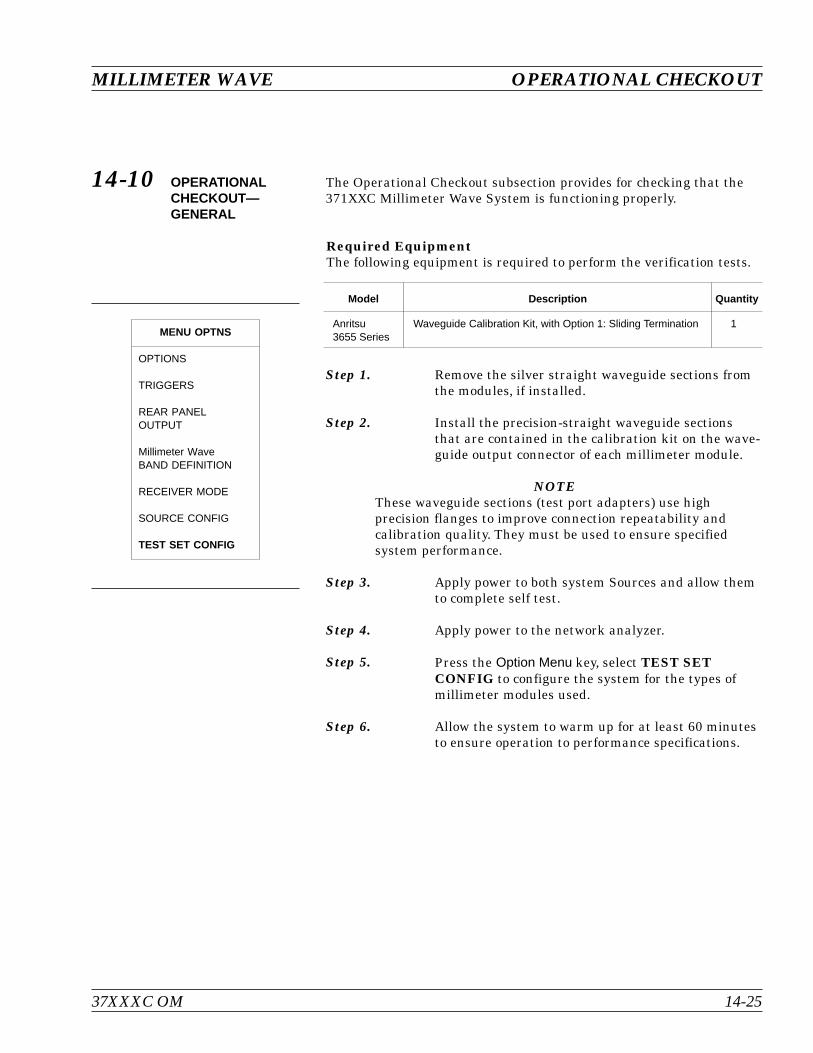
14-10 OPERATIONALCHECKOUT—GENERAL
The Operational Checkout subsection provides for checking that the371XXC Millimeter Wave System is functioning properly.
Required EquipmentThe following equipment is required to perform the verification tests.
Model Description Quantity
Anritsu3655 Series
Waveguide Calibration Kit, with Option 1: Sliding Termination 1
Step 1. Remove the silver straight waveguide sections fromthe modules, if installed.
Step 2. Install the precision-straight waveguide sectionsthat are contained in the calibration kit on the wave-guide output connector of each millimeter module.
NOTEThese waveguide sections (test port adapters) use highprecision flanges to improve connection repeatability andcalibration quality. They must be used to ensure specifiedsystem performance.
Step 3. Apply power to both system Sources and allow themto complete self test.
Step 4. Apply power to the network analyzer.
Step 5. Press the Option Menu key, select TEST SETCONFIG to configure the system for the types ofmillimeter modules used.
Step 6. Allow the system to warm up for at least 60 minutesto ensure operation to performance specifications.
37XXXC OM 14-25
MILLIMETER WAVE OPERATIONAL CHECKOUT
MENU OPTNS
OPTIONS
TRIGGERS
REAR PANELOUTPUT
Millimeter WaveBAND DEFINITION
RECEIVER MODE
SOURCE CONFIG
TEST SET CONFIG
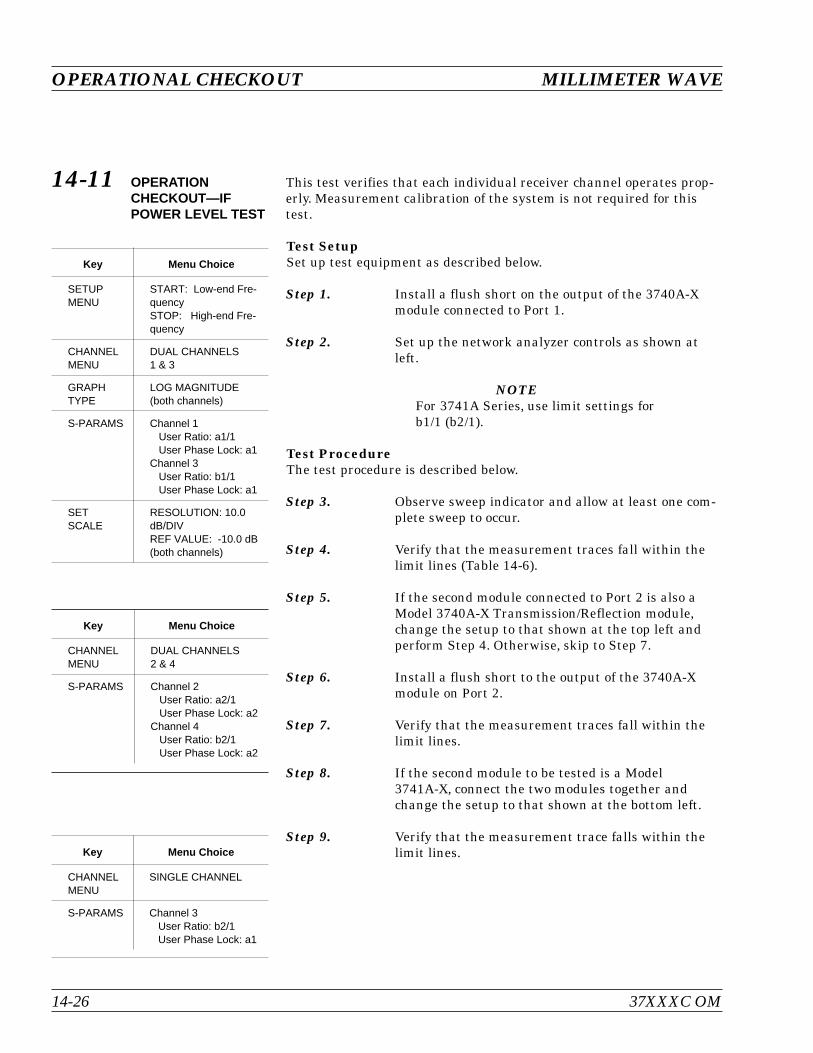
14-11 OPERATIONCHECKOUT—IFPOWER LEVEL TEST
This test verifies that each individual receiver channel operates prop-erly. Measurement calibration of the system is not required for thistest.
Test SetupSet up test equipment as described below.
Step 1. Install a flush short on the output of the 3740A-Xmodule connected to Port 1.
Step 2. Set up the network analyzer controls as shown atleft.
NOTEFor 3741A Series, use limit settings forb1/1 (b2/1).
Test ProcedureThe test procedure is described below.
Step 3. Observe sweep indicator and allow at least one com-plete sweep to occur.
Step 4. Verify that the measurement traces fall within thelimit lines (Table 14-6).
Step 5. If the second module connected to Port 2 is also aModel 3740A-X Transmission/Reflection module,change the setup to that shown at the top left andperform Step 4. Otherwise, skip to Step 7.
Step 6. Install a flush short to the output of the 3740A-Xmodule on Port 2.
Step 7. Verify that the measurement traces fall within thelimit lines.
Step 8. If the second module to be tested is a Model3741A-X, connect the two modules together andchange the setup to that shown at the bottom left.
Step 9. Verify that the measurement trace falls within thelimit lines.
OPERATIONAL CHECKOUT MILLIMETER WAVE
14-26 37XXXC OM
Key Menu Choice
SETUPMENU
START: Low-end Fre-quencySTOP: High-end Fre-quency
CHANNELMENU
DUAL CHANNELS1 & 3
GRAPHTYPE
LOG MAGNITUDE(both channels)
S-PARAMS Channel 1User Ratio: a1/1User Phase Lock: a1
Channel 3User Ratio: b1/1User Phase Lock: a1
SETSCALE
RESOLUTION: 10.0dB/DIVREF VALUE: -10.0 dB(both channels)
Key Menu Choice
CHANNELMENU
DUAL CHANNELS2 & 4
S-PARAMS Channel 2User Ratio: a2/1User Phase Lock: a2
Channel 4User Ratio: b2/1User Phase Lock: a2
Key Menu Choice
CHANNELMENU
SINGLE CHANNEL
S-PARAMS Channel 3User Ratio: b2/1User Phase Lock: a1
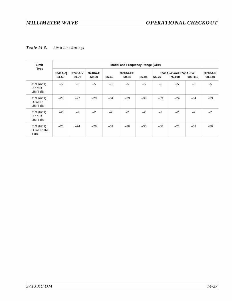
37XXXC OM 14-27
MILLIMETER WAVE OPERATIONAL CHECKOUT
LimitType
Model and Frequency Range (GHz)
3740A-Q33-50
3740A-V50-75
3740A-E60-90
3740A-EE56-60 60-85 85-94
3740A-W and 3740A-EW65-75 75-100 100-110
3740A-F90-140
a1/1 (a2/1)UPPERLIMIT dB
–5 –5 –5 –5 –5 –5 –5 –5 –5 –5
a1/1 (a2/1)LOWERLIMIT dB
–29 –27 –29 –34 –29 –39 –39 –24 –34 –39
b1/1 (b2/1)UPPERLIMIT dB
–2 –2 –2 –2 –2 –2 –2 –2 –2 –2
b1/1 (b2/1)LOWERLIMIT dB
–26 –24 –26 –31 –26 –36 –36 –21 –31 –36
Table 14-6. Limit Line Settings
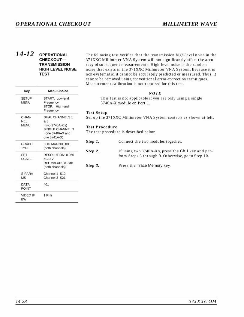
14-12 OPERATIONALCHECKOUT—TRANSMISSIONHIGH LEVEL NOISETEST
The following test verifies that the transmission high-level noise in the371XXC Millimeter VNA System will not significantly affect the accu-racy of subsequent measurements. High-level noise is the randomnoise that exists in the 371XXC Millimeter VNA System. Because it isnon-systematic, it cannot be accurately predicted or measured. Thus, itcannot be removed using conventional error-correction techniques.Measurement calibration is not required for this test.
NOTEThis test is not applicable if you are only using a single3740A-X module on Port 1.
Test SetupSet up the 371XXC Millimeter VNA System controls as shown at left.
Test ProcedureThe test procedure is described below.
Step 1. Connect the two modules together.
Step 2. If using two 3740A-X’s, press the Ch 1 key and per-form Steps 3 through 9. Otherwise, go to Step 10.
Step 3. Press the Trace Memory key.
OPERATIONAL CHECKOUT MILLIMETER WAVE
14-28 37XXXC OM
Key Menu Choice
SETUPMENU
START: Low-endFrequencySTOP: High-endFrequency
CHAN-NELMENU
DUAL CHANNELS 1& 3(two 3740A-X’s)SINGLE CHANNEL 3(one 3740A-X andone 3741A-X)
GRAPHTYPE
LOG MAGNITUDE(both channels)
SETSCALE
RESOLUTION: 0.050dB/DIVREF VALUE: 0.0 dB(both channels)
S-PARAMS
Channel 1 S12Channel 3 S21
DATAPOINT
401
VIDEO IFBW
1 KHz

Step 4. Choose VIEW DATA from the menu (left) and pressthe Enter key.
Step 5. While observing the sweep indicator, allow at leasttwo complete sweeps to occur. (One complete sweep ifusing single channel display.)
Step 6. Choose STORE DATA TO MEMORY from menuand press the Enter key.
Step 7. Choose VIEW DATA / MEMORY from the menuand press the Enter key.
Step 8. While observing the sweep indicator, allow at leasttwo complete sweeps to occur. (One complete sweep ifusing single channel display.)
Step 9. Verify that the peak-to-peak High Level Noise fallswithin the area between the two limit lines.
NOTEDisplayed data is only valid for the first fewsweeps.
Step 10. Press the Ch 3 key.
Step 11. Repeat Steps 4 through 9 for channel 3.
37XXXC OM 14-29
MILLIMETER WAVE OPERATIONAL CHECKOUT
MENU NO1
TRACE MEMORYFUNCTIONS
VIEW DATA
VIEW MEMORY
VIEW DATAAND MEMORY
VIEW DATA (/)MEMORY
SELECTTRACE MATH
STORE DATATO MEMORY
DISKOPERATIONS
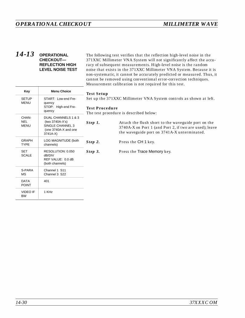
14-13 OPERATIONALCHECKOUT—REFLECTION HIGHLEVEL NOISE TEST
The following test verifies that the reflection high-level noise in the371XXC Millimeter VNA System will not significantly affect the accu-racy of subsequent measurements. High-level noise is the randomnoise that exists in the 371XXC Millimeter VNA System. Because it isnon-systematic, it cannot be accurately predicted or measured. Thus, itcannot be removed using conventional error-correction techniques.Measurement calibration is not required for this test.
Test SetupSet up the 371XXC Millimeter VNA System controls as shown at left.
Test ProcedureThe test procedure is described below:
Step 1. Attach the flush short to the waveguide port on the3740A-X on Port 1 (and Port 2, if two are used); leavethe waveguide port on 3741A-X unterminated.
Step 2. Press the CH 1 key.
Step 3. Press the Trace Memory key.
OPERATIONAL CHECKOUT MILLIMETER WAVE
14-30 37XXXC OM
Key Menu Choice
SETUPMENU
START: Low-end Fre-quencySTOP: High-end Fre-quency
CHAN-NELMENU
DUAL CHANNELS 1 & 3(two 3740A-X’s)SINGLE CHANNEL 3(one 3740A-X and one3741A-X)
GRAPHTYPE
LOG MAGNITUDE (bothchannels)
SETSCALE
RESOLUTION: 0.050dB/DIVREF VALUE: 0.0 dB(both channels)
S-PARAMS
Channel 1 S11Channel 3 S22
DATAPOINT
401
VIDEO IFBW
1 KHz
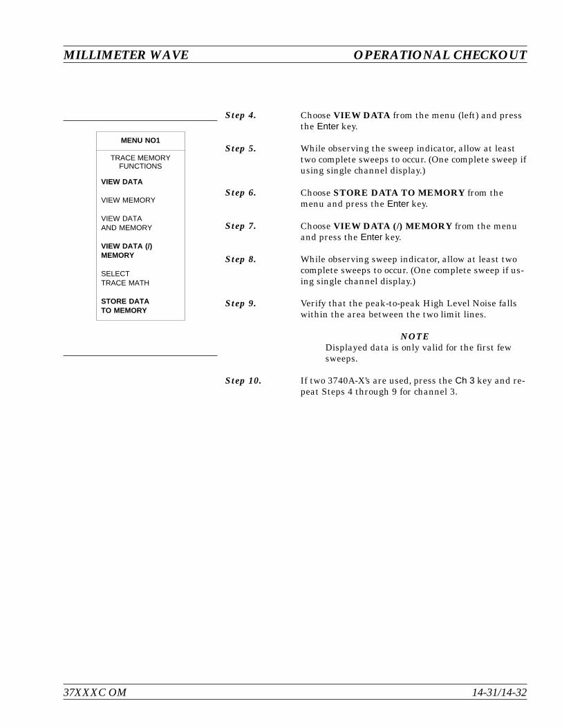
Step 4. Choose VIEW DATA from the menu (left) and pressthe Enter key.
Step 5. While observing the sweep indicator, allow at leasttwo complete sweeps to occur. (One complete sweep ifusing single channel display.)
Step 6. Choose STORE DATA TO MEMORY from themenu and press the Enter key.
Step 7. Choose VIEW DATA (/) MEMORY from the menuand press the Enter key.
Step 8. While observing sweep indicator, allow at least twocomplete sweeps to occur. (One complete sweep if us-ing single channel display.)
Step 9. Verify that the peak-to-peak High Level Noise fallswithin the area between the two limit lines.
NOTEDisplayed data is only valid for the first fewsweeps.
Step 10. If two 3740A-X’s are used, press the Ch 3 key and re-peat Steps 4 through 9 for channel 3.
MILLIMETER WAVE OPERATIONAL CHECKOUT
37XXXC OM 14-31/14-32
MENU NO1
TRACE MEMORYFUNCTIONS
VIEW DATA
VIEW MEMORY
VIEW DATAAND MEMORY
VIEW DATA (/)MEMORY
SELECTTRACE MATH
STORE DATATO MEMORY

Chapter 15ME7808A BroadbandMeasurement System
Table of Contents
15-1 INTRODUCTION. . . . . . . . . . . . . . . . . . . . . . . . . . . . . . . . . . . 15-3
15-2 SYSTEM DESCRIPTION . . . . . . . . . . . . . . . . . . . . . . . . . . . . . . 15-3
Measurement Instruments . . . . . . . . . . . . . . . . . . . . . . . . . . . . 15-3
Console and Associated Hardware . . . . . . . . . . . . . . . . . . . . . . . . 15-4
Cables . . . . . . . . . . . . . . . . . . . . . . . . . . . . . . . . . . . . . . . 15-4
15-3 INSTALLATION . . . . . . . . . . . . . . . . . . . . . . . . . . . . . . . . . . . 15-4
Console and Table Setup . . . . . . . . . . . . . . . . . . . . . . . . . . . . . 15-5
Instrument Installation into Console . . . . . . . . . . . . . . . . . . . . . . . 15-6
System Cabling . . . . . . . . . . . . . . . . . . . . . . . . . . . . . . . . . . 15-9
15-4 INITIAL ELECTRICAL TESTS . . . . . . . . . . . . . . . . . . . . . . . . . . 15-11
Millimeter Module Checkout. . . . . . . . . . . . . . . . . . . . . . . . . . . 15-11
40 MHz to 65 GHz Checkout. . . . . . . . . . . . . . . . . . . . . . . . . . . 15-12
15-5 WAFER PROBE STATION . . . . . . . . . . . . . . . . . . . . . . . . . . . . 15-13
15-6 BROADBAND MENUS, FLOW. . . . . . . . . . . . . . . . . . . . . . . . . . . 15-15
15-7 BROADBAND CALIBRATION . . . . . . . . . . . . . . . . . . . . . . . . . . . 15-16
Merging Calibrations. . . . . . . . . . . . . . . . . . . . . . . . . . . . . . . 15-16

Chapter 15ME7808A BroadbandMeasurement System
15-1 INTRODUCTION This chapter describes the ME7808A Broadband Measurement Systemand the broadband mode of operation (40 MHz to 110 GHz). For othersetup modes, refer to Chapter 14 (Millimeter Wave System), or otherpertinent chapters in this manual. Model 3742A-EW modules (65 to110 GHz) are assumed to be installed on the system, even thoughother modules are available.
The W1 Calibration Kit (P/N 3656) is designed for the purpose of per-forming coaxial calibrations with the ME7808A Vector Network Ana-lyzer up to 110 GHz. The calibration kit comprises of Open, Short, andLoad standards to enable two sets of calibrations—a Short Open LoadThru (SOLT) calibration from 40 MHz to 65 GHz, and a Triple OffsetShort (SSST) calibration from 65 to 110 GHz (refer to Chapter 7, Mea-surement Calibration for these calibration procedures). The ME7808Afirmware supports concatenation to allow merging of the two calibra-tions for broadband corrected measurements from 40 MHz to 110 GHz(discussed later in this chapter). In addition, the calibration kit in-cludes fixed and interchangeable adapters, which may be used as testport connector savers. The interchangeable adapters have one fixedend and one interchangeable end that can be changed to a male or fe-male for non-insertable device measurements.
15-2 SYSTEM DESCRIPTION The ME7808A Broadband system is normally composed of the follow-ing Anritsu instruments and accessories (your system may vary de-pending on your application):
Measurement Instruments 37397C Vector Network Analyzer with Option 12
68037C or MG3692A Synthesized Signal Generator withOption 15A
68037C or MG3692A Synthesized Signal Generator(no options necessary)
3738A Millimeter Test Set
3742A-EW Millimeter Module (quantity 2)
57215 (left) and 57216 (right) Coupler (quantity 1)
37XXXC OM 15-3

Console and AssociatedHardware
Console
Table
Mounting rails for Table (quantity 2)
Static Dissipative Mat for Table
Wrist Strap
Cables Rigid RF Cable (Upper synthesizer to 3738A)
Rigid RF Cable (Lower synthesizer to 3738A)
Cable Assembly (3742A to 3738A front panel) (quantity 2)
Cable Assembly (3738A rear panel to VNA rear panel) (quan-tity 1)
Flexible RF Cable (coupler to VNA) (quantity 2)
GPIB Cable (VNA to Synthesizer) (quantity 2)
Power Cord (quantity 4)
15-3 INSTALLATION This section describes installation and system check-out without mak-ing use of a wafer-probe test station. For instructions on installation ofthe wafer probe test station, refer to paragraph 15-5.
IMPORTANT NOTES The empty console weighs approximately 66kg
(145 pounds). Use two people to remove the console fromthe pallet.
Many of the instruments are quite heavy and requiretwo people to lift them.
Instruments should be loaded into the bottom sections ofthe console first, to prevent tipping of the console.
The VNA instrument has fragile RF cables connected toboth the front and rear panels. Be careful not to bendthese cables when handling the instrument.
If the synthesizers are not installed precisely as de-scribed below, the system will be non-functional.
We suggest using an 8 in/lb torque wrench to tightenSMA connectors (available in most Anritsu VNA Cali-bration kits) Do not tighten any connectors over 8 in/lbs.
INSTALLATION BROADBAND SYSTEM
15-4 37XXXC OM
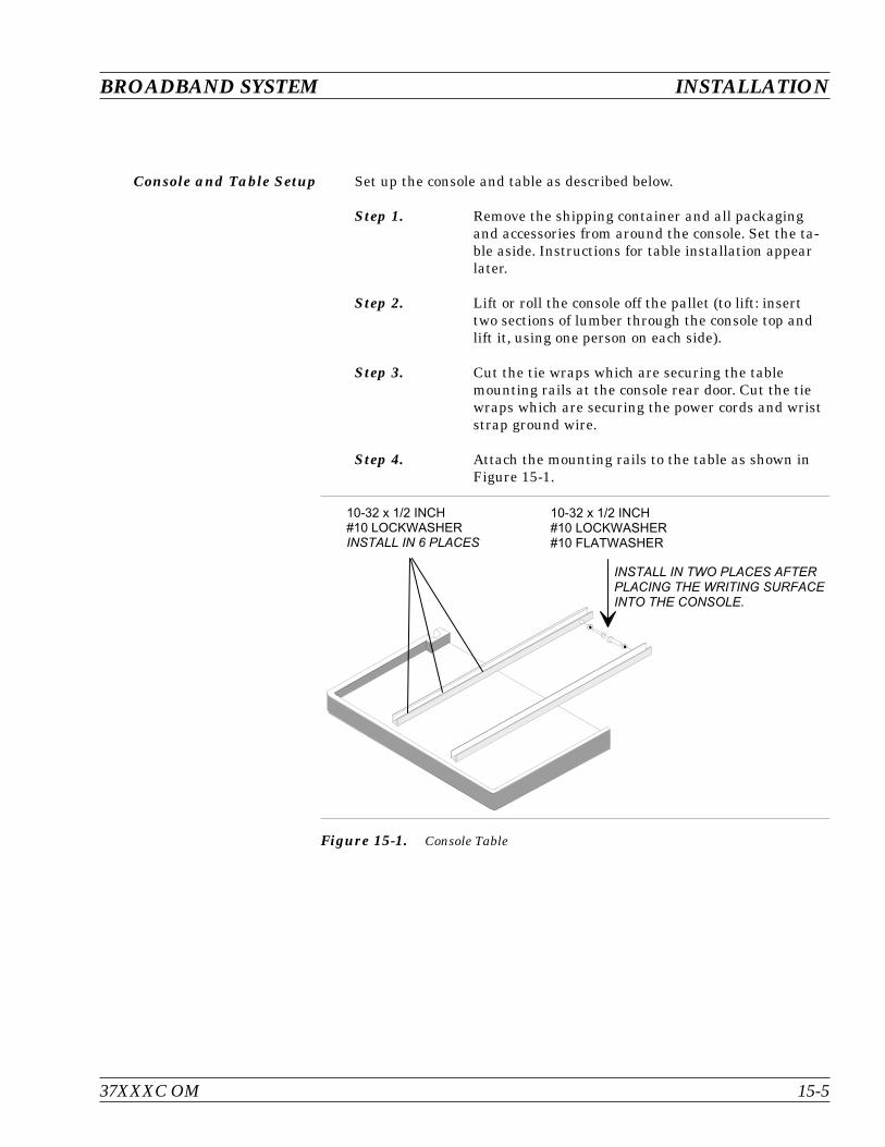
Console and Table Setup Set up the console and table as described below.
Step 1. Remove the shipping container and all packagingand accessories from around the console. Set the ta-ble aside. Instructions for table installation appearlater.
Step 2. Lift or roll the console off the pallet (to lift: inserttwo sections of lumber through the console top andlift it, using one person on each side).
Step 3. Cut the tie wraps which are securing the tablemounting rails at the console rear door. Cut the tiewraps which are securing the power cords and wriststrap ground wire.
Step 4. Attach the mounting rails to the table as shown inFigure 15-1.
37XXXC OM 15-5
BROADBAND SYSTEM INSTALLATION
7 8 : L $ "Q 7 % " Q 7 % "
7 8 : L $ "Q 7 % "
Figure 15-1. Console Table
Instrument Installationinto Console
Refer to Figures 15-2, 15-3, and 15-4 for installation of major instru-ments and cables.
Step 1. Check the rear panel serial number labels of the syn-thesizers. The instrument without Option 15 belongsin the bottom compartment (“RF” synthesizer).
Step 2. Install the synthesizer with Option 15 in the secondopening from the bottom.
Step 3. Install the VNA into the top compartment. Ensurethe three small RF cables are installed onto the frontand rear panels (one in front, and two in back).
Step 4. Install the 3738A Test Set into the compartment be-low the VNA.
Step 5. Secure all instruments in the console using thescrews provided.
Step 6. On the left front of the console, move the blackground wire away from the guide of the table-mount-ing rail, and install the table by sliding the tablerails into the guides.
Step 7. Secure the table rails at the rear of the console usingthe screws provided.
INSTALLATION BROADBAND SYSTEM
15-6 37XXXC OM
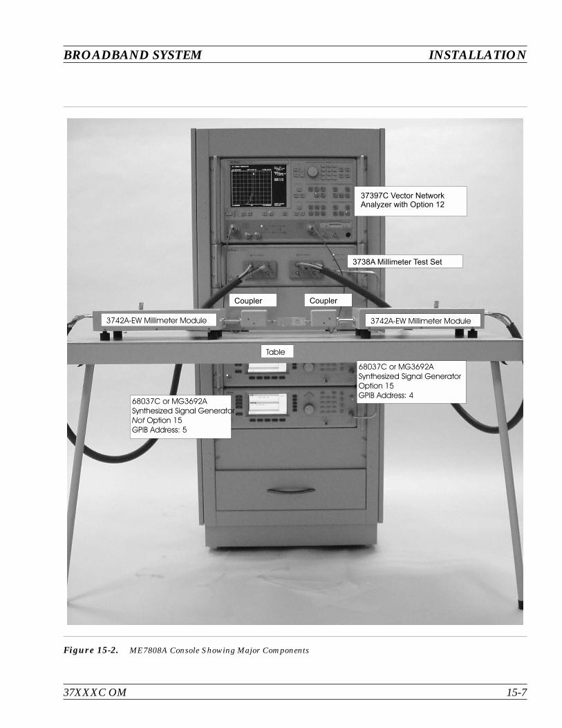
37XXXC OM 15-7
BROADBAND SYSTEM INSTALLATION
68037C or MG3692ASynthesized Signal GeneratorNot Option 15GPIB Address: 5
68037C or MG3692ASynthesized Signal GeneratorOption 15GPIB Address: 4
37397C Vector NetworkAnalyzer with Option 12
Table
Coupler Coupler
3742A-EW Millimeter Module
3738A Millimeter Test Set
3742A-EW Millimeter Module
Figure 15-2. ME7808A Console Showing Major Components
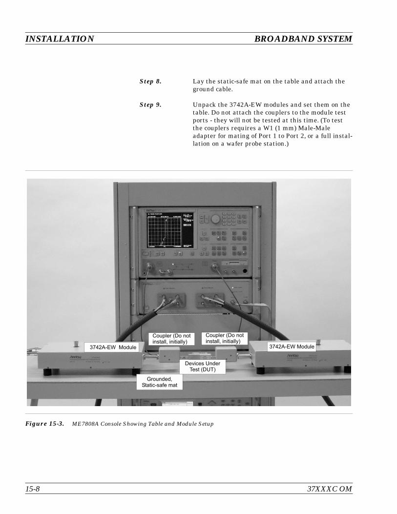
Step 8. Lay the static-safe mat on the table and attach theground cable.
Step 9. Unpack the 3742A-EW modules and set them on thetable. Do not attach the couplers to the module testports - they will not be tested at this time. (To testthe couplers requires a W1 (1 mm) Male-Maleadapter for mating of Port 1 to Port 2, or a full instal-lation on a wafer probe station.)
INSTALLATION BROADBAND SYSTEM
15-8 37XXXC OM
Coupler (Do notinstall, initially)
3742A-EW Module
Devices UnderTest (DUT)
Grounded,Static-safe mat
3742A-EW Module
Coupler (Do notinstall, initially)
Figure 15-3. ME7808A Console Showing Table and Module Setup

System Cabling Connect ME7808A system cables as described below and shown in Fig-ure 15-4 on the following page.
Step 1. From the front, connect the rigid RF cable betweenthe upper synthesizer and the 3738A LO IN connec-tor. Ensure the connectors are seated correctly andtightened securely.
Step 2. From the front, connect the rigid RF cable betweenthe bottom synthesizer and the 3738A RF IN connec-tor. Ensure the connectors are seated correctly andtightened securely.
Step 3. From the front, install the two RF cable sets betweenthe 3738A and the 3742A-EW modules. Connect ex-actly as the labels indicate.
Step 4. From the rear, unscrew the four smallchain-mounted terminations from on VNA (let themhang loose) and install the Cable Set. Connect indi-vidual cables as indicated on the labels .
Step 5. Connect one GPIB cable from the lower (Dedicated)GPIB connector of the VNA to the upper synthesizer.Connect the second GPIB cable between the two syn-thesizers.
Step 6. Insert the power cords into all 4 instruments andturn all the instruments on.
Step 7. Ensure that the two synthesizers' GPIB addressesare set correctly. The top unit should be set to ad-dress 4 and the bottom unit should be set toaddress 5. This can be verified or changed by press-ing SYSTEM |CONFIG |GPIB ADDRESS and en-tering the appropriate GPIB address.
37XXXC OM 15-9
BROADBAND SYSTEM INSTALLATION
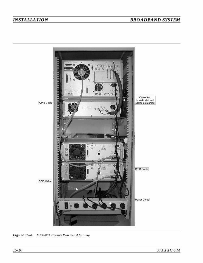
INSTALLATION BROADBAND SYSTEM
15-10 37XXXC OM
Cable Set.Install individual
cables as markedGPIB Cable
GPIB Cable
GPIB Cable
Power Cords
Figure 15-4. ME7808A Console Rear Panel Cabling

15-4 INITIAL ELECTRICALTESTS
Perform electrical tests as described below:
Millimeter Module Checkout Check out the Millimeter Modules as described below:
Step 1. Ensure the VNA displays “Self-Test Passed”. Ifself-test fails, contact your Anritsu Representative.
Step 2. To put the system into the “Millimeter” mode, pressthe OPTION MENU key, and select TEST SETCONFIG / MILLIMETER WAVE, then press<ENTER>. Select the correct WR modules for yoursystem.
Step 3. Connect the Port 1 and Port 2 3742A-EW waveguidetest ports tightly together.
Step 4. If error messages appear, or the system does notsweep:
Look for error messages displayed on thesynthesizers’ front panels (“ovn cold” is not anerror)
Double-check all cable connections
Verify the synthesizers’ GPIB addresses are set cor-rectly
Verify the power control verniers on top of the3742A-EW modules are set to maximum power(fully CW)
Step 5. Ensure the system is set to default settings (PressDEFAULT PROGRAM two times to reset the sys-tem).
Step 6. Set the VNA display as follows:a. Press CHANNEL MENU and select
SINGLE CHANNELb. Press CH3c. Press GRAPH TYPE and select LOG MAGNITUDE
Step 7. Ensure the display is similar to Figure 15-5 (nextpage).
Step 8. Press CH2.
Step 9. Press GRAPH TYPE and select LOG MAGNITUDE.
37XXXC OM 15-11
BROADBAND SYSTEM INITIAL ELECTRICAL TESTS
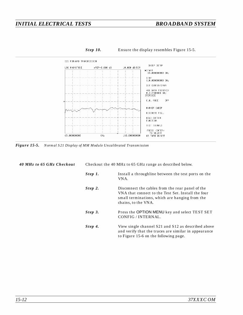
Step 10. Ensure the display resembles Figure 15-5.
40 MHz to 65 GHz Checkout Checkout the 40 MHz to 65 GHz range as described below.
Step 1. Install a throughline between the test ports on theVNA.
Step 2. Disconnect the cables from the rear panel of theVNA that connect to the Test Set. Install the foursmall terminations, which are hanging from thechains, to the VNA.
Step 3. Press the OPTION MENU key and select TEST SETCONFIG / INTERNAL.
Step 4. View single channel S21 and S12 as described aboveand verify that the traces are similar in appearanceto Figure 15-6 on the following page.
INITIAL ELECTRICAL TESTS BROADBAND SYSTEM
15-12 37XXXC OM
Figure 15-5. Normal S21 Display of MM Module Uncalibrated Transmission
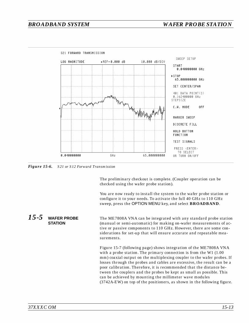
The preliminary checkout is complete. (Coupler operation can bechecked using the wafer probe station).
You are now ready to install the system to the wafer probe station orconfigure it to your needs. To activate the full 40 GHz to 110 GHzsweep, press the OPTION MENU key, and select BROADBAND.
15-5 WAFER PROBESTATION
The ME7808A VNA can be integrated with any standard probe station(manual or semi-automatic) for making on-wafer measurements of ac-tive or passive components to 110 GHz. However, there are some con-siderations for set-up that will ensure accurate and repeatable mea-surements.
Figure 15-7 (following page) shows integration of the ME7808A VNAwith a probe station. The primary connection is from the W1 (1.00mm) coaxial output on the multiplexing coupler to the wafer probes. Iflosses through the probes and cables are excessive, the result can be apoor calibration. Therefore, it is recommended that the distance be-tween the couplers and the probes be kept as small as possible. Thiscan be achieved by mounting the millimeter wave modules(3742A-EW) on top of the positioners, as shown in the following figure.
37XXXC OM 15-13
BROADBAND SYSTEM WAFER PROBE STATION
Figure 15-6. S21 or S12 Forward Transmission
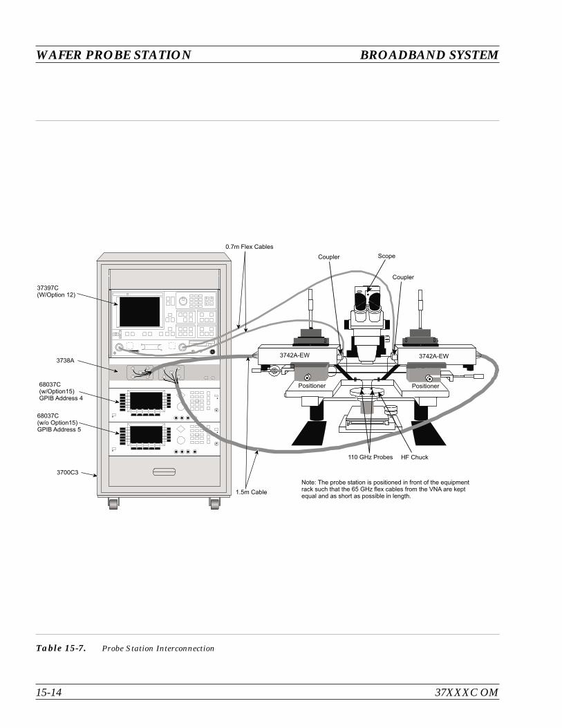
WAFER PROBE STATION BROADBAND SYSTEM
15-14 37XXXC OM
Note: The probe station is positioned in front of the equipmentrack such that the 65 GHz flex cables from the VNA are keptequal and as short as possible in length.
110 GHz Probes HF Chuck
1.5m Cable
3700C3
68037C(w/o Option15)GPIB Address 5
68037C(w/Option15)GPIB Address 4
3738A
37397C(W/Option 12)
0.7m Flex Cables
Coupler Scope
Coupler
3742A-EW3742A-EW
Positioner Positioner
Table 15-7. Probe Station Interconnection
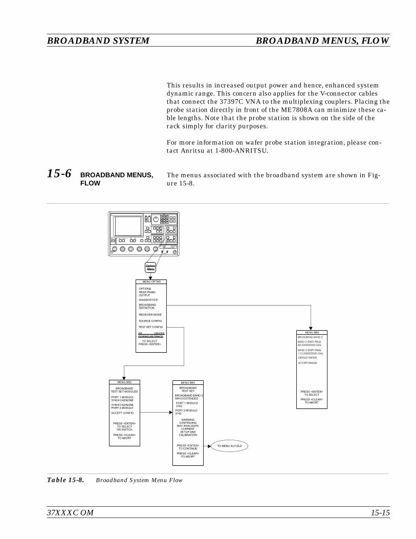
This results in increased output power and hence, enhanced systemdynamic range. This concern also applies for the V-connector cablesthat connect the 37397C VNA to the multiplexing couplers. Placing theprobe station directly in front of the ME7808A can minimize these ca-ble lengths. Note that the probe station is shown on the side of therack simply for clarity purposes.
For more information on wafer probe station integration, please con-tact Anritsu at 1-800-ANRITSU.
15-6 BROADBAND MENUS,FLOW
The menus associated with the broadband system are shown in Fig-ure 15-8.
37XXXC OM 15-15
BROADBAND SYSTEM BROADBAND MENUS, FLOW
OptionMenu
MENU OPTNS
MENU BB2 MENU BB3
REAR PANELOUTPUT
DIAGNOSTICS
BROADBANDDEFINITION
OPTIONS
RECEIVER MODE
TO SELECTPRESS <ENTER>
PRESS <ENTER>TO SELECT
PRESS <CLEAR>TO ABORT
SOURCE CONFIG
TEST SET CONFIG
RF ON/OFFDURING RETRACE
MENU BB4
BROADBAND BAND 2
BAND 2 START FREQ65.000000000 GHz
BAND 2 ST0PT FREQ110.000000000 GHz
DEFAULT RANGE
ACCEPT RANGE
TO MENU SU1/SU2
BROADBANDTEST SET MODULES
PORT 1 MODULE3740/41/42/NONE
3740/41/42/NONEPORT 2 MODULE
ACCEPT CONFIG
PRESS <ENTER>TO SELECTOR SWITCH
PRESS <CLEAR>TO ABORT
PRESS <CLEAR>TO ABORT
BROADBANDTEST SET
BROADBAND BAND 2WR10 EXTENDED
PORT 1 MODULE3742
PORT 2 MODULE3742
WARNINGCONTINUING
MAY INVALIDATECURRENT
SETUP ANDCALIBRATION
PRESS <ENTER>TO CONTINUE
Table 15-8. Broadband System Menu Flow

15-7 BROADBANDCALIBRATION
Once the SOLT and SSST calibrations have been performed and saved,they can be merged for a continuous, single sweep broadband calibra-tion. (Refer to Chapter 7, Measurement Calibration for SOLT andSSST calibration procedures.)
Merging Calibrations Merge the calibrations as follows:
Step 1. Open the applications menu by pressing the APPLkey.
Step 2. Select MERGE CAL FILES to open menu MRG1 (left).
Step 3. Select MERGE CAL FILES again to open menuMRG2 (below left).
Step 4. Select READ CAL FILE 1 FROM HARD DISK or READCAL FILE 1 FROM FLOPPY DISK to select the SOLTcalibration file.
Step 5. After loading the SOLT cal file, select READ CALFILE 2 FROM HARD DISK or READ CAL FILE 2FROM FLOPPY DISK from menu MRG3 (below right)and select the SSST calibration file. This stepmerges the calibration files together.
Step 6. The system is now ready for calibrated measure-ments over the 40 MHz to 110 GHz frequency range.
BROADBAND CALIBRATION BROADBAND SYSTEM
15-16 37XXXC OM
MENU MRG1
MERGE CAL FILES
CAL FILES MUSTEXIST IN THECURRENT DIRECTORY
MERGE CAL FILES
PRESS <ENTER>TO SELECT
MENU MRG2 MENU MRG3
MERGE CAL FILES MERGE CAL FILES
READ CAL FILE 1FROM HARD DISK
READ CAL FILE 2FROM HARD DISK
READ CAL FILE 1FROM FLOPPYDISK
READ CAL FILE 2FROM FLOPPYDISK
PRESS <ENTER>TO SELECT
PRESS <ENTER>TO SELECT
PRESS <CLEAR>TO ABORT
PRESS <CLEAR>TO ABORT
Contents
Menu ACAL, AutoCal Menu. . . . . . . . . . . . . . . . . . . . . . . . . . . A-12
Menu ACAL_SETUP, AutoCal Setup Menu . . . . . . . . . . . . . . . . . . A-13
Menu ACAL_S11 1 PORT, AutoCal S11 1 Port Menu . . . . . . . . . . . . . A-14
Menu ACAL_S22 1 PORT, AutoCal S22 1 Port Menu . . . . . . . . . . . . . A-15
Menu ACAL_FULL, AutoCal Full Menu . . . . . . . . . . . . . . . . . . . . A-16
Menu ACAL_AR, AutoCal Adapter Removal Menu . . . . . . . . . . . . . . A-17
Menu ACAL_UTILS, AutoCal Utilities Menu . . . . . . . . . . . . . . . . . A-18
Menu ACAL_CHAR, AutoCal Characterization Menu . . . . . . . . . . . . . A-19
Menu APPL, Applications Menu . . . . . . . . . . . . . . . . . . . . . . . . A-20
Menu BB2, Broadband Select Menu1 . . . . . . . . . . . . . . . . . . . . . . A-21
Menu BB3, Broadband Select Menu 2 . . . . . . . . . . . . . . . . . . . . . A-22
Menu BB4, Broadband Select Menu3 . . . . . . . . . . . . . . . . . . . . . . A-23
Menu BW1 or CAL_BW1, Select Video Bandwidth . . . . . . . . . . . . . . A-24
Menu C1, Select Calibration Data Points . . . . . . . . . . . . . . . . . . . . A-25
Menu C2, Frequency Range of Calibration (Start/Stop) . . . . . . . . . . . . A-26
Menu C2_CENTER, Frequency Range of Calibration (Center/Span) . . . . . A-27
Menu C2A, Insert Individual Frequencies . . . . . . . . . . . . . . . . . . . A-28
Menu C2C, Calibration Range—Harmonic Cal for Time Domain . . . . . . . A-29
Menu C2B, Single Point Calibration . . . . . . . . . . . . . . . . . . . . . . A-29
Menu C2D, Fill Frequency Ranges . . . . . . . . . . . . . . . . . . . . . . . A-30
Menu C3, Confirm Calibration Parameters. . . . . . . . . . . . . . . . . . . A-31
Menu C3A, Confirm Calibration Parameters . . . . . . . . . . . . . . . . . . A-32
Menu C3B, Confirm Calibration Parameters . . . . . . . . . . . . . . . . . . A-33
Menu C3C, Confirm Calibration Parameters . . . . . . . . . . . . . . . . . . A-34
37XXXC OM A-1
Appendix AFront Panel Menus,Alphabetical Listing
Menu C3D, Confirm Calibration Parameters . . . . . . . . . . . . . . . . . . A-35
Menu C3E, Confirm Calibration Parameters . . . . . . . . . . . . . . . . . . A-36
Menu C3F, Confirm Calibration Parameters . . . . . . . . . . . . . . . . . . A-37
Menu C3G, Confirm Calibration Parameters . . . . . . . . . . . . . . . . . . A-38
Menu C3H, Confirm Calibration Parameters. . . . . . . . . . . . . . . . . . A-39
Menu C3I, ConfirmCalibration Parameter 2 . . . . . . . . . . . . . . . . . . A-40
Menu C3J, ConfirmCalibration Parameter 3 . . . . . . . . . . . . . . . . . . A-41
Menu C4_P1/C4_P2, Select Connector Type . . . . . . . . . . . . . . . . . . A-42
Menu C4A_P1/C4A_P2, Select Connector Type . . . . . . . . . . . . . . . . A-43
Menu C4B, Select Open and Short Type . . . . . . . . . . . . . . . . . . . . A-44
Menu C5, Select Calibration Type . . . . . . . . . . . . . . . . . . . . . . . A-45
Menu C5A, Select 1 Path 2 Port Calibration Type . . . . . . . . . . . . . . . A-46
Menu C5B, Select Transmission Freq Response Calibration Type . . . . . . A-46
Menu C5C, Select Reflection Only Calibration Type . . . . . . . . . . . . . . A-47
Menu C5D, Select Use of Isolation . . . . . . . . . . . . . . . . . . . . . . . A-47
Menu C6, Select Load Type . . . . . . . . . . . . . . . . . . . . . . . . . . . A-48
Menu C6A, Enter Broadband Load Impedance. . . . . . . . . . . . . . . . . A-48
Menu C6B, Enter Broadband Load Impedance. . . . . . . . . . . . . . . . . A-48
Menu C7-Series, Begin Calibration Sequence . . . . . . . . . . . . . . . . . A-49
Menu C8, Slide Load to Position X . . . . . . . . . . . . . . . . . . . . . . . A-49
Menu C9A, Connect Device 1, Line . . . . . . . . . . . . . . . . . . . . . . . A-50
Menu C9, Connect Throughline . . . . . . . . . . . . . . . . . . . . . . . . . A-50
Menu C9C, Connect Device 2, Line . . . . . . . . . . . . . . . . . . . . . . . A-51
Menu C9B, Connect Device 2, Line/Lowband. . . . . . . . . . . . . . . . . . A-51
Menu C11, Begin Calibration . . . . . . . . . . . . . . . . . . . . . . . . . . A-52
Menu C11A, Select Calibration Method . . . . . . . . . . . . . . . . . . . . A-53
Menu C12_P1/C12_P2, Enter the Capacitance Coefficients for Open Devices A-54
Menu C12A_P1/C12A_P2, Enter the Offset Length . . . . . . . . . . . . . . A-55
Menu C13, Set Reflection Pairing Menu . . . . . . . . . . . . . . . . . . . . A-56
Menu C13A, Set Reflection Pairing Menu . . . . . . . . . . . . . . . . . . . A-57
Menu C13B, Set Reflection Pairing Menu . . . . . . . . . . . . . . . . . . . A-57
Menu C14, Select Port X Offset Short Connecotr Type. . . . . . . . . . . . . A-58
Menu C14A, Select Port X Offset Short . . . . . . . . . . . . . . . . . . . . . A-58
A-2 37XXXC OM
CONTENTS ALPHABETICAL LISTING

Menu C15, Select Waveguide Kit to Use . . . . . . . . . . . . . . . . . . . . A-59
Menu C15A, Enter Waveguide Parameters . . . . . . . . . . . . . . . . . . . A-60
Menu C15B, Enter Waveguide Parameters . . . . . . . . . . . . . . . . . . . A-60
Menu C15C, Select Waveguide Kit to Use . . . . . . . . . . . . . . . . . . . A-61
Menu C15D, Enter Waveguide Parameters . . . . . . . . . . . . . . . . . . . A-62
Menu C16A, Enter Microstrip Parameters . . . . . . . . . . . . . . . . . . . A-63
Menu C16, Select Microstrip Parameters . . . . . . . . . . . . . . . . . . . . A-63
Menu C17, Enter Line Impedance . . . . . . . . . . . . . . . . . . . . . . . A-64
Menu C18, Change LRL/LRM Parameters . . . . . . . . . . . . . . . . . . . A-64
Menu C18A, Change LRL/LRM Parameters . . . . . . . . . . . . . . . . . . A-65
Menu C18B, Change LRL/LRM Parameters—Two Band Calibration. . . . . A-66
Menu C19, Change LRL/LRM Parameters . . . . . . . . . . . . . . . . . . . A-67
Menu C20, Change Through Parameters . . . . . . . . . . . . . . . . . . . . A-68
Menu C21A, Port X Offset Short 1 . . . . . . . . . . . . . . . . . . . . . . . A-69
Menu C21B, Port X Offset Short 2 . . . . . . . . . . . . . . . . . . . . . . . A-70
Menu C21C, Port X Offset Short 3 . . . . . . . . . . . . . . . . . . . . . . . A-71
Menu Cal_Completed . . . . . . . . . . . . . . . . . . . . . . . . . . . . . . A-72
Menu Cal_Applied . . . . . . . . . . . . . . . . . . . . . . . . . . . . . . . . A-73
Menu Cal_EM, Enhancement Menu for Calibration . . . . . . . . . . . . . . A-74
Menu CAR1, Adapter Removal 1 . . . . . . . . . . . . . . . . . . . . . . . . A-75
Menu CAR2, Adapter Removal 2 . . . . . . . . . . . . . . . . . . . . . . . . A-75
Menu EXT_CAR, Adapter Removal Help Menu . . . . . . . . . . . . . . . . A-76
Menu CAR3, Adapter Removal 3 . . . . . . . . . . . . . . . . . . . . . . . . A-77
Menu CAR4, Adapter Removal 4 . . . . . . . . . . . . . . . . . . . . . . . . A-77
Menu CM, Select Display Mode . . . . . . . . . . . . . . . . . . . . . . . . . A-78
Menu DE1, E/O Measurement . . . . . . . . . . . . . . . . . . . . . . . . . A-79
Menu EXT_DE1, E/O Measurement . . . . . . . . . . . . . . . . . . . . . . A-79
Menu DE2, O/E Measurement . . . . . . . . . . . . . . . . . . . . . . . . . A-80
Menu EXT_DE2, O/E Measurement . . . . . . . . . . . . . . . . . . . . . . A-80
Menu DE3, E/O Measurement . . . . . . . . . . . . . . . . . . . . . . . . . A-81
Menu DE3A, E/O Measurement. . . . . . . . . . . . . . . . . . . . . . . . . A-81
Menu DE4, De-embed Network . . . . . . . . . . . . . . . . . . . . . . . . . A-82
Menu DE4A, De-embed Network . . . . . . . . . . . . . . . . . . . . . . . . A-82
ALPHABETICAL LISTING CONTENTS
37XXXC OM A-3

Menu DE5, De-embed O/E S2P . . . . . . . . . . . . . . . . . . . . . . . . . A-83
Menu DE5A, De-embed O/E S2P . . . . . . . . . . . . . . . . . . . . . . . . A-83
Menu DE6, Generate E/O S2P Characterization . . . . . . . . . . . . . . . . A-84
Menu DE7, O/E Measurement . . . . . . . . . . . . . . . . . . . . . . . . . A-85
Menu DE7A, O/E Measurement. . . . . . . . . . . . . . . . . . . . . . . . . A-85
Menu DF1, Discrete Fill . . . . . . . . . . . . . . . . . . . . . . . . . . . . . A-86
Menu DF2, Insert Individual Frequencies . . . . . . . . . . . . . . . . . . . A-87
Menu DFLT, Default Program Selected . . . . . . . . . . . . . . . . . . . . . A-88
Menu DG1, Diagnostics 1 . . . . . . . . . . . . . . . . . . . . . . . . . . . . A-89
Menu DG3, Diagnostics 3 . . . . . . . . . . . . . . . . . . . . . . . . . . . . A-90
Menu DG2, Troubleshooting. . . . . . . . . . . . . . . . . . . . . . . . . . . A-90
Menu DSK_FD, Floppy Disk Utilities. . . . . . . . . . . . . . . . . . . . . . A-91
Menu DSK_HD, Hard Disk Utilities . . . . . . . . . . . . . . . . . . . . . . A-92
Menu DSK2, Select File to Read . . . . . . . . . . . . . . . . . . . . . . . . A-93
Menu DSK3, Select File to Overwrite. . . . . . . . . . . . . . . . . . . . . . A-94
Menu DSK6, Type of Files to Delete . . . . . . . . . . . . . . . . . . . . . . A-95
Menu DSK7, Select File to Delete . . . . . . . . . . . . . . . . . . . . . . . . A-96
Menu DSK8, Type of Files to Copy . . . . . . . . . . . . . . . . . . . . . . . A-97
Menu DSK9, Select File to Copy . . . . . . . . . . . . . . . . . . . . . . . . A-98
Menu DSK10, Capture Tabular Data . . . . . . . . . . . . . . . . . . . . . . A-99
Menu DSK11, Format Floppy Disk . . . . . . . . . . . . . . . . . . . . . . . A-99
Menu DSK12, Format Hard Disk . . . . . . . . . . . . . . . . . . . . . . . . A-99
Menu EM, Enhancement Menu . . . . . . . . . . . . . . . . . . . . . . . . A-100
Menu GC1, Swept Frequency Gain Compression . . . . . . . . . . . . . . . A-101
Menu EXT_GC1, Gain Compression Help Menu 1 . . . . . . . . . . . . . . A-102
Menu GC2, Swept Power Gain Compression 1 . . . . . . . . . . . . . . . . A-103
Menu EXT_GC2, Gain Compression Help Menu 2 . . . . . . . . . . . . . . A-104
Menu GC3, Swept Power Gain Compression 2 . . . . . . . . . . . . . . . . A-105
Menu EXT_GC3, Gain Compression Help Menu 3 . . . . . . . . . . . . . . A-106
Menu GC4, Multiple Frequency Gain Compression 1 . . . . . . . . . . . . A-107
Menu GC4_ABORT, Multiple Frequency Gain Compression 2 . . . . . . . . A-107
Menu EXT_GC4, Gain Compression Help Menu 4 . . . . . . . . . . . . . . A-108
Menu GC_DF2, Swept Power Frequencies . . . . . . . . . . . . . . . . . . A-109
A-4 37XXXC OM
CONTENTS ALPHABETICAL LISTING

Menu EXT_GC_DF2, Gain Compression Help Menu . . . . . . . . . . . . A-110
Menu GC_NORM, Normalize S21 . . . . . . . . . . . . . . . . . . . . . . . A-110
Menu GC_RCVR, Receiver Calibration . . . . . . . . . . . . . . . . . . . . A-111
Menu GC_SU2, Swept Power Gain Compression 2 . . . . . . . . . . . . . . A-112
Menu GC_SU8A, Calibrate for Linear Power . . . . . . . . . . . . . . . . . A-113
Menu GC_SU8A-ABORT, Abort Calibrate for Linear Power . . . . . . . . . A-114
Menu EXT_GC_SU8A, Gain Compression Help Menu . . . . . . . . . . . . A-115
Menu GC_S21OPT, S21 Options . . . . . . . . . . . . . . . . . . . . . . . . A-116
Menu GP5, Select Name . . . . . . . . . . . . . . . . . . . . . . . . . . . . A-117
Menu GP7, Display GPIB Status . . . . . . . . . . . . . . . . . . . . . . . A-118
Menu GT1/CAL_GT1, Select Graph Type . . . . . . . . . . . . . . . . . . . A-119
Menu GT2/CAL_GT2, Select Graph Type . . . . . . . . . . . . . . . . . . . A-120
Menu L1, Set Limits—Magnitude and Phase . . . . . . . . . . . . . . . . . A-121
Menu L2, Set Limits—Linear Polar . . . . . . . . . . . . . . . . . . . . . . A-122
Menu L3, Set Limits—Linear Polar/Smith Chart . . . . . . . . . . . . . . . A-123
Menu L4, Set Limits—Log Magnitude. . . . . . . . . . . . . . . . . . . . . A-124
Menu L5, Set Limits—Phase. . . . . . . . . . . . . . . . . . . . . . . . . . A-125
Menu L6, Set Limits—Log Polar. . . . . . . . . . . . . . . . . . . . . . . . A-126
Menu L7, Set Limits—Group Delay . . . . . . . . . . . . . . . . . . . . . . A-127
Menu L8, Set Limits—Linear Magnitude . . . . . . . . . . . . . . . . . . . A-128
Menu L9, Set Limits—Linear Magnitude and Phase . . . . . . . . . . . . A-129
Menu L10, Set Limits—Real Values . . . . . . . . . . . . . . . . . . . . . . A-130
Menu L11, Set Limits—Imaginary Values . . . . . . . . . . . . . . . . . . A-131
Menu L12, Set Limits—Real and Imaginary Values . . . . . . . . . . . . . A-132
Menu L13, Set Limits—SWR . . . . . . . . . . . . . . . . . . . . . . . . . A-133
Menu L14, Set Limits—Power Out . . . . . . . . . . . . . . . . . . . . . . A-134
Menu LD1, Define Upper Limit Segment . . . . . . . . . . . . . . . . . . . A-135
Menu LD2, Define Lower Limit Segmen . . . . . . . . . . . . . . . . . . . A-136
Menu LF1, Set Limit Frequencies—Log Mag . . . . . . . . . . . . . . . . . A-137
Menu LF2, Set Limit Frequencies—Phase . . . . . . . . . . . . . . . . . . A-138
Menu LF3, Set Limit Frequencies—Group Delay. . . . . . . . . . . . . . . A-139
Menu LF4, Set Limit Frequencies—Linear Mag . . . . . . . . . . . . . . . A-140
Menu LF5, Set Limit Frequencies—SWR . . . . . . . . . . . . . . . . . . . A-141
ALPHABETICAL LISTING CONTENTS
37XXXC OM A-5

Menu LF6, Set Limit Frequencies—Real . . . . . . . . . . . . . . . . . . . A-142
Menu LF7, Set Limit Frequencies—Imaginary . . . . . . . . . . . . . . . . A-143
Menu LF8, Set Limit Frequencies—Power Out . . . . . . . . . . . . . . . . A-144
Menu LSX, Segmented Limits . . . . . . . . . . . . . . . . . . . . . . . . . A-145
Menu LTST, Test Limits . . . . . . . . . . . . . . . . . . . . . . . . . . . . A-146
Menu M1, Set Markers . . . . . . . . . . . . . . . . . . . . . . . . . . . . A-147
Menu M2, Select REF Marker . . . . . . . . . . . . . . . . . . . . . . . . A-148
Menu M3, Select Readout Marker . . . . . . . . . . . . . . . . . . . . . . . A-149
Menu M4, Readout Marker . . . . . . . . . . . . . . . . . . . . . . . . . . A-150
Menu M5, Set REF Marker Readout . . . . . . . . . . . . . . . . . . . . . A-151
Menu M6, Marker X All Displayed Channels . . . . . . . . . . . . . . . . . A-152
Menu M7, Search . . . . . . . . . . . . . . . . . . . . . . . . . . . . . . . . A-153
Menu M8, Filter Parameters . . . . . . . . . . . . . . . . . . . . . . . . . . A-154
Menu M8A, Filter Setup . . . . . . . . . . . . . . . . . . . . . . . . . . . . A-155
Menu M9, Marker Readout Functions. . . . . . . . . . . . . . . . . . . . . A-156
Menu MMW1, Millimeter Wave Test Set Band . . . . . . . . . . . . . . . . A-157
Menu MMW2, Millimeter Wave Test Set Modules . . . . . . . . . . . . . . A-158
Menu MMW3, Millimeter Wave Test Set . . . . . . . . . . . . . . . . . . . A-159
Menu MMW4, mm Wave Band. . . . . . . . . . . . . . . . . . . . . . . . . A-160
Menu EXT_MMW4 . . . . . . . . . . . . . . . . . . . . . . . . . . . . . . . A-161
Menu MRG1, Merge Calibration Menu . . . . . . . . . . . . . . . . . . . . A-162
Menu EXT_MRG1, Merge Calibration Menu . . . . . . . . . . . . . . . . . A-162
Menu MRG2, Merge Calibration Menu . . . . . . . . . . . . . . . . . . . . A-163
Menu MRG3, Merge Calibration Menu . . . . . . . . . . . . . . . . . . . . A-163
Menu NO1, Trace Memory Functions . . . . . . . . . . . . . . . . . . . . . A-164
Menu NO2, Select Trace Math . . . . . . . . . . . . . . . . . . . . . . . . . A-165
Menu NO3, Trace Memory Disk Functions . . . . . . . . . . . . . . . . . . A-165
Menu OM1, Multiple Source Control Menu . . . . . . . . . . . . . . . . . . A-166
Menu OM1A, Source Lock Polarity Menu . . . . . . . . . . . . . . . . . . . A-167
Menu OM2, Define Bands Menu . . . . . . . . . . . . . . . . . . . . . . . . A-168
Menu OM3, Edit System Equations . . . . . . . . . . . . . . . . . . . . . . A-169
Menu OPTNS, Select Options . . . . . . . . . . . . . . . . . . . . . . . . . A-170
Menu ORP1, Rear Panel Output Control . . . . . . . . . . . . . . . . . . . A-171
A-6 37XXXC OM
CONTENTS ALPHABETICAL LISTING
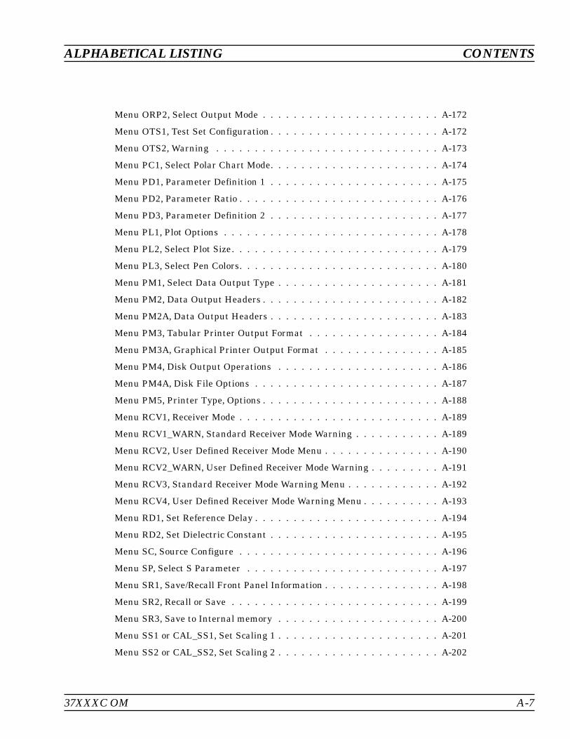
Menu ORP2, Select Output Mode . . . . . . . . . . . . . . . . . . . . . . . A-172
Menu OTS1, Test Set Configuration . . . . . . . . . . . . . . . . . . . . . . A-172
Menu OTS2, Warning . . . . . . . . . . . . . . . . . . . . . . . . . . . . . A-173
Menu PC1, Select Polar Chart Mode. . . . . . . . . . . . . . . . . . . . . . A-174
Menu PD1, Parameter Definition 1 . . . . . . . . . . . . . . . . . . . . . . A-175
Menu PD2, Parameter Ratio . . . . . . . . . . . . . . . . . . . . . . . . . . A-176
Menu PD3, Parameter Definition 2 . . . . . . . . . . . . . . . . . . . . . . A-177
Menu PL1, Plot Options . . . . . . . . . . . . . . . . . . . . . . . . . . . . A-178
Menu PL2, Select Plot Size. . . . . . . . . . . . . . . . . . . . . . . . . . . A-179
Menu PL3, Select Pen Colors. . . . . . . . . . . . . . . . . . . . . . . . . . A-180
Menu PM1, Select Data Output Type . . . . . . . . . . . . . . . . . . . . . A-181
Menu PM2, Data Output Headers . . . . . . . . . . . . . . . . . . . . . . . A-182
Menu PM2A, Data Output Headers . . . . . . . . . . . . . . . . . . . . . . A-183
Menu PM3, Tabular Printer Output Format . . . . . . . . . . . . . . . . . A-184
Menu PM3A, Graphical Printer Output Format . . . . . . . . . . . . . . . A-185
Menu PM4, Disk Output Operations . . . . . . . . . . . . . . . . . . . . . A-186
Menu PM4A, Disk File Options . . . . . . . . . . . . . . . . . . . . . . . . A-187
Menu PM5, Printer Type, Options . . . . . . . . . . . . . . . . . . . . . . . A-188
Menu RCV1, Receiver Mode . . . . . . . . . . . . . . . . . . . . . . . . . . A-189
Menu RCV1_WARN, Standard Receiver Mode Warning . . . . . . . . . . . A-189
Menu RCV2, User Defined Receiver Mode Menu . . . . . . . . . . . . . . . A-190
Menu RCV2_WARN, User Defined Receiver Mode Warning . . . . . . . . . A-191
Menu RCV3, Standard Receiver Mode Warning Menu . . . . . . . . . . . . A-192
Menu RCV4, User Defined Receiver Mode Warning Menu . . . . . . . . . . A-193
Menu RD1, Set Reference Delay . . . . . . . . . . . . . . . . . . . . . . . . A-194
Menu RD2, Set Dielectric Constant . . . . . . . . . . . . . . . . . . . . . . A-195
Menu SC, Source Configure . . . . . . . . . . . . . . . . . . . . . . . . . . A-196
Menu SP, Select S Parameter . . . . . . . . . . . . . . . . . . . . . . . . . A-197
Menu SR1, Save/Recall Front Panel Information . . . . . . . . . . . . . . . A-198
Menu SR2, Recall or Save . . . . . . . . . . . . . . . . . . . . . . . . . . . A-199
Menu SR3, Save to Internal memory . . . . . . . . . . . . . . . . . . . . . A-200
Menu SS1 or CAL_SS1, Set Scaling 1 . . . . . . . . . . . . . . . . . . . . . A-201
Menu SS2 or CAL_SS2, Set Scaling 2 . . . . . . . . . . . . . . . . . . . . . A-202
ALPHABETICAL LISTING CONTENTS
37XXXC OM A-7
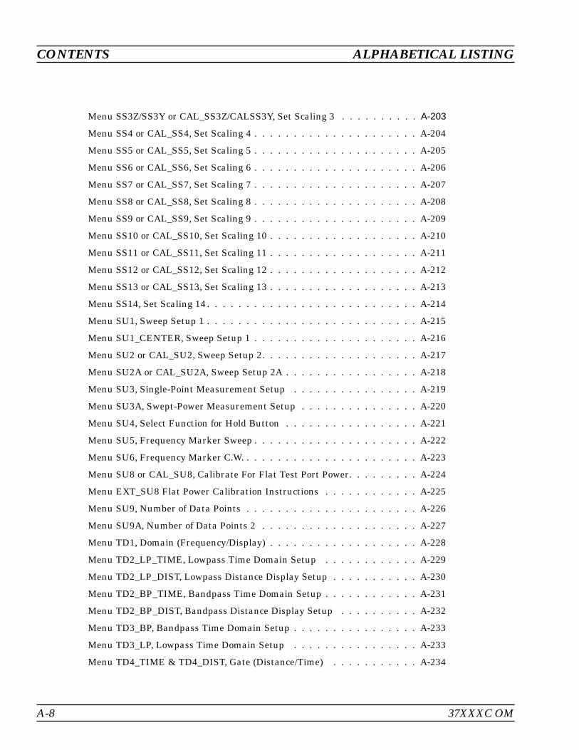
Menu SS3Z/SS3Y or CAL_SS3Z/CALSS3Y, Set Scaling 3 . . . . . . . . . . A-203
Menu SS4 or CAL_SS4, Set Scaling 4 . . . . . . . . . . . . . . . . . . . . . A-204
Menu SS5 or CAL_SS5, Set Scaling 5 . . . . . . . . . . . . . . . . . . . . . A-205
Menu SS6 or CAL_SS6, Set Scaling 6 . . . . . . . . . . . . . . . . . . . . . A-206
Menu SS7 or CAL_SS7, Set Scaling 7 . . . . . . . . . . . . . . . . . . . . . A-207
Menu SS8 or CAL_SS8, Set Scaling 8 . . . . . . . . . . . . . . . . . . . . . A-208
Menu SS9 or CAL_SS9, Set Scaling 9 . . . . . . . . . . . . . . . . . . . . . A-209
Menu SS10 or CAL_SS10, Set Scaling 10 . . . . . . . . . . . . . . . . . . . A-210
Menu SS11 or CAL_SS11, Set Scaling 11 . . . . . . . . . . . . . . . . . . . A-211
Menu SS12 or CAL_SS12, Set Scaling 12 . . . . . . . . . . . . . . . . . . . A-212
Menu SS13 or CAL_SS13, Set Scaling 13 . . . . . . . . . . . . . . . . . . . A-213
Menu SS14, Set Scaling 14 . . . . . . . . . . . . . . . . . . . . . . . . . . . A-214
Menu SU1, Sweep Setup 1 . . . . . . . . . . . . . . . . . . . . . . . . . . . A-215
Menu SU1_CENTER, Sweep Setup 1 . . . . . . . . . . . . . . . . . . . . . A-216
Menu SU2 or CAL_SU2, Sweep Setup 2. . . . . . . . . . . . . . . . . . . . A-217
Menu SU2A or CAL_SU2A, Sweep Setup 2A . . . . . . . . . . . . . . . . . A-218
Menu SU3, Single-Point Measurement Setup . . . . . . . . . . . . . . . . A-219
Menu SU3A, Swept-Power Measurement Setup . . . . . . . . . . . . . . . A-220
Menu SU4, Select Function for Hold Button . . . . . . . . . . . . . . . . . A-221
Menu SU5, Frequency Marker Sweep . . . . . . . . . . . . . . . . . . . . . A-222
Menu SU6, Frequency Marker C.W. . . . . . . . . . . . . . . . . . . . . . . A-223
Menu SU8 or CAL_SU8, Calibrate For Flat Test Port Power. . . . . . . . . A-224
Menu EXT_SU8 Flat Power Calibration Instructions . . . . . . . . . . . . A-225
Menu SU9, Number of Data Points . . . . . . . . . . . . . . . . . . . . . . A-226
Menu SU9A, Number of Data Points 2 . . . . . . . . . . . . . . . . . . . . A-227
Menu TD1, Domain (Frequency/Display) . . . . . . . . . . . . . . . . . . . A-228
Menu TD2_LP_TIME, Lowpass Time Domain Setup . . . . . . . . . . . . A-229
Menu TD2_LP_DIST, Lowpass Distance Display Setup . . . . . . . . . . . A-230
Menu TD2_BP_TIME, Bandpass Time Domain Setup . . . . . . . . . . . . A-231
Menu TD2_BP_DIST, Bandpass Distance Display Setup . . . . . . . . . . A-232
Menu TD3_BP, Bandpass Time Domain Setup . . . . . . . . . . . . . . . . A-233
Menu TD3_LP, Lowpass Time Domain Setup . . . . . . . . . . . . . . . . A-233
Menu TD4_TIME & TD4_DIST, Gate (Distance/Time) . . . . . . . . . . . A-234
A-8 37XXXC OM
CONTENTS ALPHABETICAL LISTING
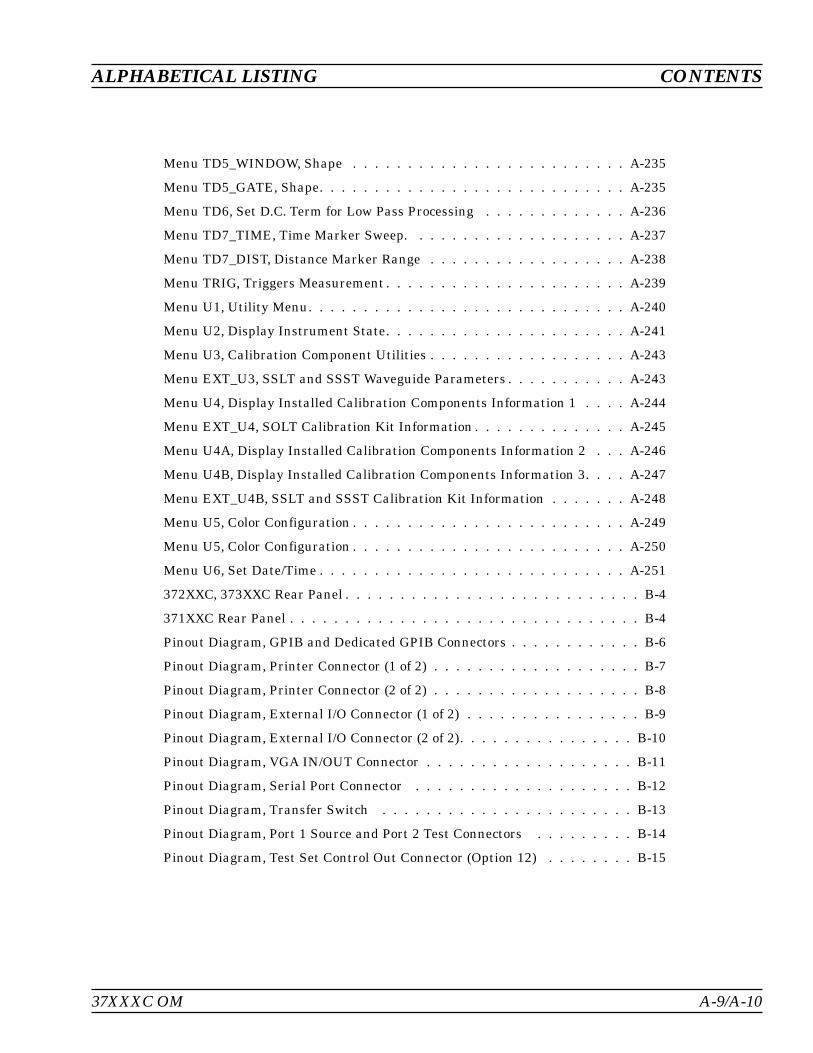
Menu TD5_WINDOW, Shape . . . . . . . . . . . . . . . . . . . . . . . . . A-235
Menu TD5_GATE, Shape. . . . . . . . . . . . . . . . . . . . . . . . . . . . A-235
Menu TD6, Set D.C. Term for Low Pass Processing . . . . . . . . . . . . . A-236
Menu TD7_TIME, Time Marker Sweep. . . . . . . . . . . . . . . . . . . . A-237
Menu TD7_DIST, Distance Marker Range . . . . . . . . . . . . . . . . . . A-238
Menu TRIG, Triggers Measurement . . . . . . . . . . . . . . . . . . . . . . A-239
Menu U1, Utility Menu. . . . . . . . . . . . . . . . . . . . . . . . . . . . . A-240
Menu U2, Display Instrument State. . . . . . . . . . . . . . . . . . . . . . A-241
Menu U3, Calibration Component Utilities . . . . . . . . . . . . . . . . . . A-243
Menu EXT_U3, SSLT and SSST Waveguide Parameters . . . . . . . . . . . A-243
Menu U4, Display Installed Calibration Components Information 1 . . . . A-244
Menu EXT_U4, SOLT Calibration Kit Information . . . . . . . . . . . . . . A-245
Menu U4A, Display Installed Calibration Components Information 2 . . . A-246
Menu U4B, Display Installed Calibration Components Information 3. . . . A-247
Menu EXT_U4B, SSLT and SSST Calibration Kit Information . . . . . . . A-248
Menu U5, Color Configuration . . . . . . . . . . . . . . . . . . . . . . . . . A-249
Menu U5, Color Configuration . . . . . . . . . . . . . . . . . . . . . . . . . A-250
Menu U6, Set Date/Time . . . . . . . . . . . . . . . . . . . . . . . . . . . . A-251
372XXC, 373XXC Rear Panel . . . . . . . . . . . . . . . . . . . . . . . . . . . B-4
371XXC Rear Panel . . . . . . . . . . . . . . . . . . . . . . . . . . . . . . . . B-4
Pinout Diagram, GPIB and Dedicated GPIB Connectors . . . . . . . . . . . . B-6
Pinout Diagram, Printer Connector (1 of 2) . . . . . . . . . . . . . . . . . . . B-7
Pinout Diagram, Printer Connector (2 of 2) . . . . . . . . . . . . . . . . . . . B-8
Pinout Diagram, External I/O Connector (1 of 2) . . . . . . . . . . . . . . . . B-9
Pinout Diagram, External I/O Connector (2 of 2). . . . . . . . . . . . . . . . B-10
Pinout Diagram, VGA IN/OUT Connector . . . . . . . . . . . . . . . . . . . B-11
Pinout Diagram, Serial Port Connector . . . . . . . . . . . . . . . . . . . . B-12
Pinout Diagram, Transfer Switch . . . . . . . . . . . . . . . . . . . . . . . B-13
Pinout Diagram, Port 1 Source and Port 2 Test Connectors . . . . . . . . . B-14
Pinout Diagram, Test Set Control Out Connector (Option 12) . . . . . . . . B-15
ALPHABETICAL LISTING CONTENTS
37XXXC OM A-9/A-10


Appendix AFront Panel Menus,Alphabetical Listing
A-1 INTRODUCTION This appendix provides descriptions for all menu choices. Menus arearranged in alphabetical order by their name (C1, SU2, DSK1, etc.).
A-2 MENUS A listing of all of the menus contained in this appendix is provided inthe contents section at the beginning of this appendix. This listinggives the menu's call sign, name, and page number.
37XXXC OM A-11
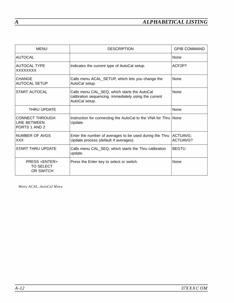
A-12 37XXXC OM
A ALPHABETICAL LISTING
MENU DESCRIPTION GPIB COMMAND
AUTOCAL None
AUTOCAL TYPEXXXXXXXX
Indicates the current type of AutoCal setup. ACF2P?
CHANGEAUTOCAL SETUP
Calls menu ACAL_SETUP, which lets you change theAutoCal setup.
None
START AUTOCAL Calls menu CAL_SEQ, which starts the AutoCalcalibration sequencing immediately using the currentAutoCal setup.
None
THRU UPDATE None
CONNECT THROUGHLINE BETWEENPORTS 1 AND 2
Instruction for connecting the AutoCal to the VNA for ThruUpdate.
None
NUMBER OF AVGSXXX
Enter the number of averages to be used during the ThruUpdate process (default 4 averages).
ACTUAVG;ACTUAVG?
START THRU UPDATE Calls menu CAL_SEQ, which starts the Thru calibrationupdate.
BEGTU
PRESS <ENTER>TO SELECTOR SWITCH
Press the Enter key to select or switch. None
Menu ACAL, AutoCal Menu
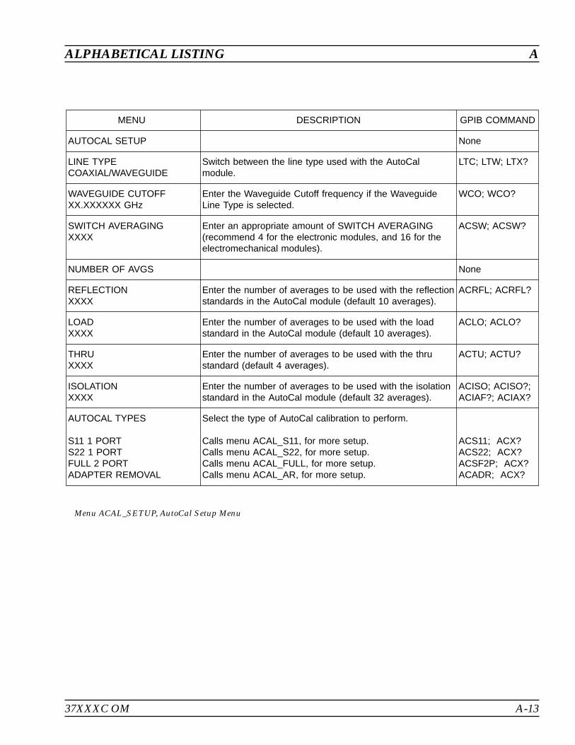
37XXXC OM A-13
ALPHABETICAL LISTING A
MENU DESCRIPTION GPIB COMMAND
AUTOCAL SETUP None
LINE TYPECOAXIAL/WAVEGUIDE
Switch between the line type used with the AutoCalmodule.
LTC; LTW; LTX?
WAVEGUIDE CUTOFFXX.XXXXXX GHz
Enter the Waveguide Cutoff frequency if the WaveguideLine Type is selected.
WCO; WCO?
SWITCH AVERAGINGXXXX
Enter an appropriate amount of SWITCH AVERAGING(recommend 4 for the electronic modules, and 16 for theelectromechanical modules).
ACSW; ACSW?
NUMBER OF AVGS None
REFLECTIONXXXX
Enter the number of averages to be used with the reflectionstandards in the AutoCal module (default 10 averages).
ACRFL; ACRFL?
LOADXXXX
Enter the number of averages to be used with the loadstandard in the AutoCal module (default 10 averages).
ACLO; ACLO?
THRUXXXX
Enter the number of averages to be used with the thrustandard (default 4 averages).
ACTU; ACTU?
ISOLATIONXXXX
Enter the number of averages to be used with the isolationstandard in the AutoCal module (default 32 averages).
ACISO; ACISO?;ACIAF?; ACIAX?
AUTOCAL TYPES
S11 1 PORTS22 1 PORTFULL 2 PORTADAPTER REMOVAL
Select the type of AutoCal calibration to perform.
Calls menu ACAL_S11, for more setup.Calls menu ACAL_S22, for more setup.Calls menu ACAL_FULL, for more setup.Calls menu ACAL_AR, for more setup.
ACS11; ACX?ACS22; ACX?ACSF2P; ACX?ACADR; ACX?
Menu ACAL_SETUP, AutoCal Setup Menu
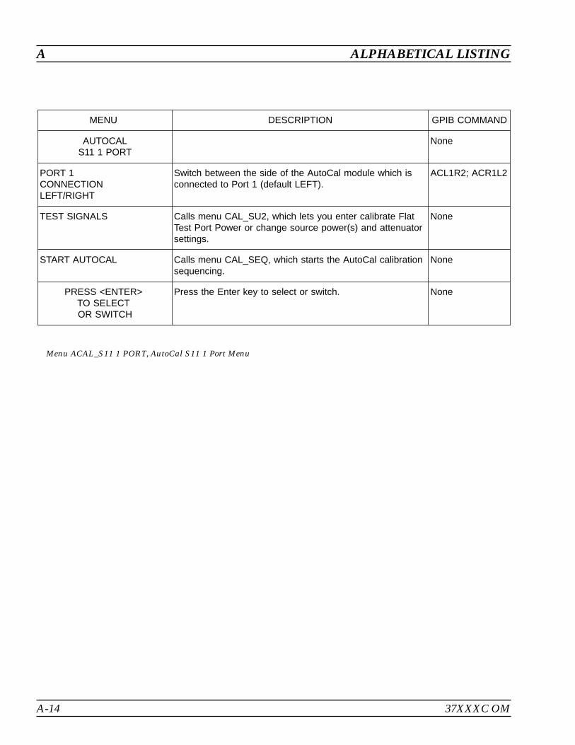
A-14 37XXXC OM
A ALPHABETICAL LISTING
MENU DESCRIPTION GPIB COMMAND
AUTOCALS11 1 PORT
None
PORT 1CONNECTIONLEFT/RIGHT
Switch between the side of the AutoCal module which isconnected to Port 1 (default LEFT).
ACL1R2; ACR1L2
TEST SIGNALS Calls menu CAL_SU2, which lets you enter calibrate FlatTest Port Power or change source power(s) and attenuatorsettings.
None
START AUTOCAL Calls menu CAL_SEQ, which starts the AutoCal calibrationsequencing.
None
PRESS <ENTER>TO SELECTOR SWITCH
Press the Enter key to select or switch. None
Menu ACAL_S11 1 PORT, AutoCal S11 1 Port Menu
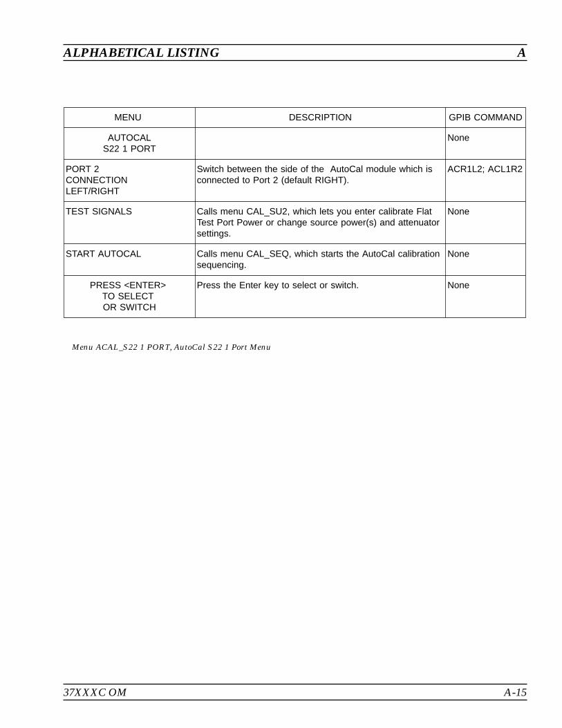
37XXXC OM A-15
ALPHABETICAL LISTING A
MENU DESCRIPTION GPIB COMMAND
AUTOCALS22 1 PORT
None
PORT 2CONNECTIONLEFT/RIGHT
Switch between the side of the AutoCal module which isconnected to Port 2 (default RIGHT).
ACR1L2; ACL1R2
TEST SIGNALS Calls menu CAL_SU2, which lets you enter calibrate FlatTest Port Power or change source power(s) and attenuatorsettings.
None
START AUTOCAL Calls menu CAL_SEQ, which starts the AutoCal calibrationsequencing.
None
PRESS <ENTER>TO SELECTOR SWITCH
Press the Enter key to select or switch. None
Menu ACAL_S22 1 PORT, AutoCal S22 1 Port Menu

A-16 37XXXC OM
A ALPHABETICAL LISTING
MENU DESCRIPTION GPIB COMMAND
AUTOCALFULL 2 PORTS
None
ISOLATIONAVERAGING
None
OMIT Select to omit the isolation step. ACOMIT
DEFAULT Select to use the Default value during the isolation step. ACDEF
AVERAGINGFACTORXXXX
Select for user defined averaging factor during the isolationstep.
ACIAF; ACIAF?
THRU TYPECALIBRATION/TRUE
Switch between the Thru in the AutoCal module(CALIBRATOR) and your own port-to-port Thru (TRUE) tobe use in the Thru Update (default CALIBRATOR).
ACF2TT;ACF2TC;ACF2TX?
PORT CONFIGL=1, R=2R=1, L=2
Switch between the side of the AutoCal module which isconnected to Port 1 and Port 2 (default LEFT connected toPort 1, RIGHT connected to Port 2).
ACL1R2; ACRIL2
TEST SIGNALS Calls menu CAL_SU2, which lets you enter calibrate FlatTest Port Power or change source power(s) and attenuatorsettings.
None
START AUTOCAL Calls menu CAL_SEQ, which starts the AutoCal calibrationsequencing.
None
PRESS <ENTER>TO SELECTOR SWITCH
Press the Enter key to select or switch. None
Menu ACAL_FULL, AutoCal Full Menu

37XXXC OM A-17
ALPHABETICAL LISTING A
MENU DESCRIPTION GPIB COMMAND
AUTOCALADAPTER REMOVAL
None
ISOLATIONAVERAGING
None
OMIT Select to omit the isolation step. ACOMIT
DEFAULT Select to use the Default value during the isolation step. ACDEF
AVERAGINGFACTORXXXX
Select for user defined averaging factor during the isolationstep.
ACIAF
PORT CONFIGADAPT & L=1, R=2L=1, ADAPT&R=2ADAPT&R=1, L=2R=1, ADAPT & L=2
Switch between the side of the AutoCal module andadapter which is connected to Port 1 and Port 2 (defaultLEFT connected to Adapter which is then connected toPort 1, RIGHT connected to Port 2).
ACAL1R2;ACL1AR2;ACAR1L2;ACR1AL2;ACARP?
TEST SIGNALS Calls menu CAL_SU2, which lets you enter calibrate FlatTest Port Power or change source power(s) and attenuatorsettings.
None
START AUTOCAL Calls menu CAL_SEQ, which starts the AutoCal calibrationsequencing.
None
PRESS <ENTER>TO SELECTOR SWITCH
Press the Enter key to select or switch. None
Menu ACAL_AR, AutoCal Adapter Removal Menu
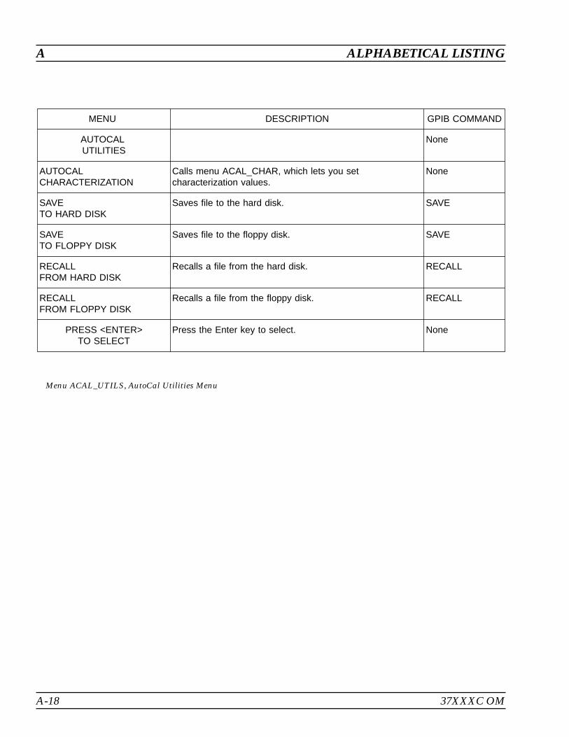
A-18 37XXXC OM
A ALPHABETICAL LISTING
MENU DESCRIPTION GPIB COMMAND
AUTOCALUTILITIES
None
AUTOCALCHARACTERIZATION
Calls menu ACAL_CHAR, which lets you setcharacterization values.
None
SAVETO HARD DISK
Saves file to the hard disk. SAVE
SAVETO FLOPPY DISK
Saves file to the floppy disk. SAVE
RECALLFROM HARD DISK
Recalls a file from the hard disk. RECALL
RECALLFROM FLOPPY DISK
Recalls a file from the floppy disk. RECALL
PRESS <ENTER>TO SELECT
Press the Enter key to select. None
Menu ACAL_UTILS, AutoCal Utilities Menu
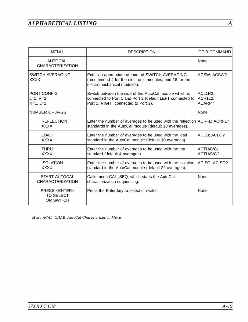
37XXXC OM A-19
ALPHABETICAL LISTING A
MENU DESCRIPTION GPIB COMMAND
AUTOCALCHARACTERIZATION
None
SWITCH AVERAGINGXXXX
Enter an appropriate amount of SWITCH AVERAGING(recommend 4 for the electronic modules, and 16 for theelectromechanical modules).
ACSW; ACSW?
PORT CONFIGL=1, R=2R=1, L=2
Switch between the side of the AutoCal module which isconnected to Port 1 and Port 2 (default LEFT connected toPort 1, RIGHT connected to Port 2).
ACL1R2;ACR1L2;ACARP?
NUMBER OF AVGS None
REFLECTIONXXXX
Enter the number of averages to be used with the reflectionstandards in the AutoCal module (default 10 averages).
ACRFL; ACRFL?
LOADXXXX
Enter the number of averages to be used with the loadstandard in the AutoCal module (default 10 averages).
ACLO; ACLO?
THRUXXXX
Enter the number of averages to be used with the thrustandard (default 4 averages).
ACTUAVG;ACTUAVG?
ISOLATIONXXXX
Enter the number of averages to be used with the isolationstandard in the AutoCal module (default 32 averages).
ACISO; ACISO?
START AUTOCALCHARACTERIZATION
Calls menu CAL_SEQ, which starts the AutoCalcharacterization sequencing.
None
PRESS <ENTER>TO SELECTOR SWITCH
Press the Enter key to select or switch. None
Menu ACAL_CHAR, AutoCal Characterization Menu

A-20 37XXXC OM
A ALPHABETICAL LISTING
MENU DESCRIPTION GPIB COMMAND
APPLICATIONS None
ADAPTER REMOVAL Calls menu CAR1, which provides options for removing anadapter.
None
SWEPT FREQUENCYGAIN COMPRESSION
Calls menu GC1, which provides options for gaincompression.
None
SWEPT POWERGAIN COMPRESSION
Calls menu GC2, which provides options for gaincompression.
None
E/O MEASUREMENT Calls menu DE1 and EXT_DE1, which provide informationand options for the E/O measurement application.
None
O/E MEASUREMENT Calls menu DE2 and EXT_DE2, which provide informationand options for the O/E measurement application.
None
MERGE CAL FILES Calls menu MRG1. None
PRESS <ENTER>TO SELECT
Pressing the ENTER key implements your selection. None
Menu APPL, Applications Menu
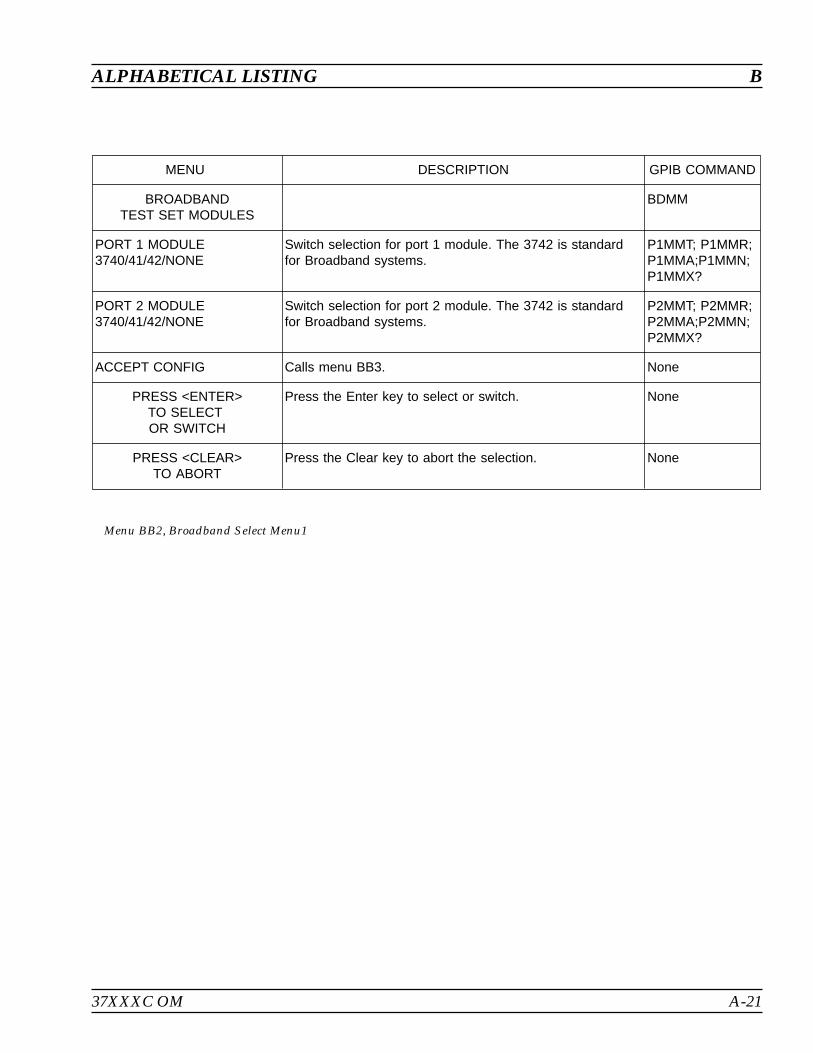
37XXXC OM A-21
ALPHABETICAL LISTING B
MENU DESCRIPTION GPIB COMMAND
BROADBANDTEST SET MODULES
BDMM
PORT 1 MODULE3740/41/42/NONE
Switch selection for port 1 module. The 3742 is standardfor Broadband systems.
P1MMT; P1MMR;P1MMA;P1MMN;P1MMX?
PORT 2 MODULE3740/41/42/NONE
Switch selection for port 2 module. The 3742 is standardfor Broadband systems.
P2MMT; P2MMR;P2MMA;P2MMN;P2MMX?
ACCEPT CONFIG Calls menu BB3. None
PRESS <ENTER>TO SELECTOR SWITCH
Press the Enter key to select or switch. None
PRESS <CLEAR>TO ABORT
Press the Clear key to abort the selection. None
Menu BB2, Broadband Select Menu1

A-22 37XXXC OM
B ALPHABETICAL LISTING
MENU DESCRIPTION GPIB COMMAND
BROADBANDTEST SET
SELBB
BROADBAND BAND 2WR10 EXTENDED
Provides information for selections made in menu BB2(previous menu).
None
PORT 1 MODULE3742
P1MMT; P1MMR;P1MMA;P1MMN;P1MMX?
PORT 2 MODULE3742
P2MMT; P2MMR;P2MMA;P2MMN;P2MMX?
WARNINGCONTINUING
MAY INVALIDATECURRENT
SETUP ANDCALIBRATION
None
PRESS <ENTER>TO CONTINUE
Implements your broadband selection and calls menu SU1or SU3.
None
PRESS <CLEAR>TO ABORT
Pressing the Clear key aborts your broadband systemselection and calls menu OST1.
None
Menu BB3, Broadband Select Menu 2
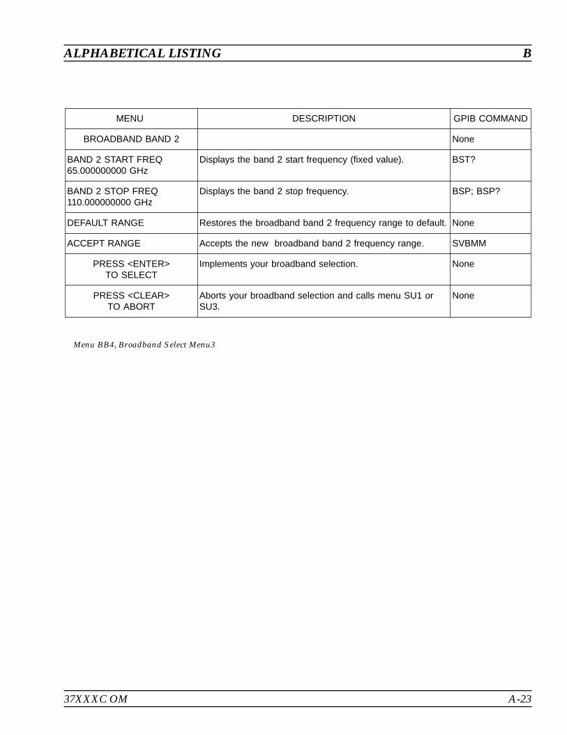
37XXXC OM A-23
ALPHABETICAL LISTING B
MENU DESCRIPTION GPIB COMMAND
BROADBAND BAND 2 None
BAND 2 START FREQ65.000000000 GHz
Displays the band 2 start frequency (fixed value). BST?
BAND 2 STOP FREQ110.000000000 GHz
Displays the band 2 stop frequency. BSP; BSP?
DEFAULT RANGE Restores the broadband band 2 frequency range to default. None
ACCEPT RANGE Accepts the new broadband band 2 frequency range. SVBMM
PRESS <ENTER>TO SELECT
Implements your broadband selection. None
PRESS <CLEAR>TO ABORT
Aborts your broadband selection and calls menu SU1 orSU3.
None
Menu BB4, Broadband Select Menu3

A-24 37XXXC OM
B ALPHABETICAL LISTING
MENU DESCRIPTION GPIB COMMAND
SELECT VIDEOBANDWIDTH
None
MAXIMUM(10 kHz)
Selects video bandwidth to be 10 kHz. IF4; IFX?
NORMAL(1 kHz)
Selects video bandwidth to be 1 kHz. IF3; IFN; IFX?
REDUCED(100 Hz)
Selects video bandwidth to be 100 Hz. IF2; IFR; IFX?
MINIMUM(10 Hz)
Selects video bandwidth to be 10 Hz. IF1; IFM; IFX?
PRESS <ENTER>TO SELECT
AND RESUME CAL
Pressing the ENTER key implements your selection. The“AND RESUME CAL” text appears when menu is accessedduring calibration.
None
Menu BW1 or CAL_BW1, Select Video Bandwidth
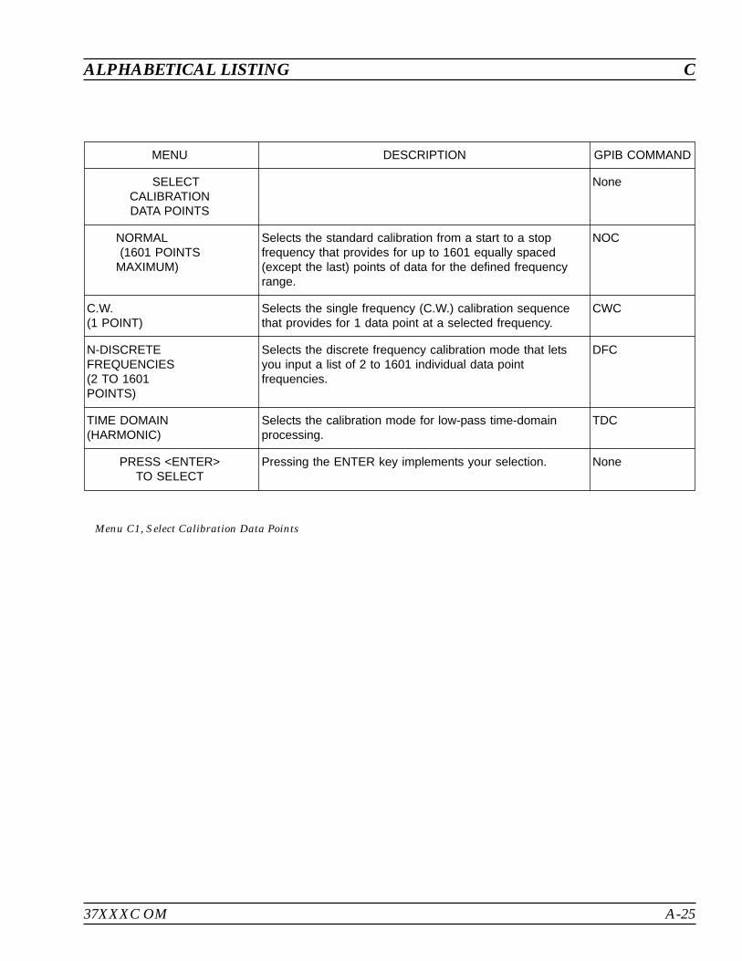
37XXXC OM A-25
ALPHABETICAL LISTING C
MENU DESCRIPTION GPIB COMMAND
SELECTCALIBRATIONDATA POINTS
None
NORMAL(1601 POINTS
MAXIMUM)
Selects the standard calibration from a start to a stopfrequency that provides for up to 1601 equally spaced(except the last) points of data for the defined frequencyrange.
NOC
C.W.(1 POINT)
Selects the single frequency (C.W.) calibration sequencethat provides for 1 data point at a selected frequency.
CWC
N-DISCRETEFREQUENCIES(2 TO 1601POINTS)
Selects the discrete frequency calibration mode that letsyou input a list of 2 to 1601 individual data pointfrequencies.
DFC
TIME DOMAIN(HARMONIC)
Selects the calibration mode for low-pass time-domainprocessing.
TDC
PRESS <ENTER>TO SELECT
Pressing the ENTER key implements your selection. None
Menu C1, Select Calibration Data Points
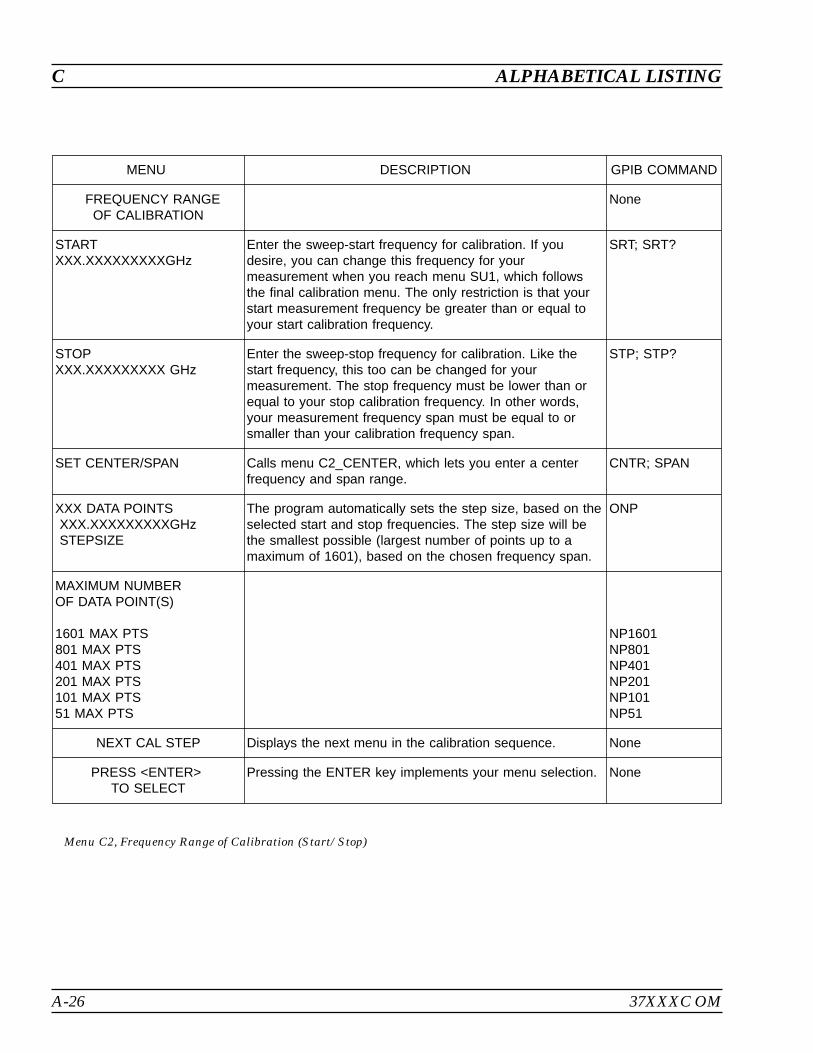
A-26 37XXXC OM
C ALPHABETICAL LISTING
MENU DESCRIPTION GPIB COMMAND
FREQUENCY RANGEOF CALIBRATION
None
STARTXXX.XXXXXXXXXGHz
Enter the sweep-start frequency for calibration. If youdesire, you can change this frequency for yourmeasurement when you reach menu SU1, which followsthe final calibration menu. The only restriction is that yourstart measurement frequency be greater than or equal toyour start calibration frequency.
SRT; SRT?
STOPXXX.XXXXXXXXX GHz
Enter the sweep-stop frequency for calibration. Like thestart frequency, this too can be changed for yourmeasurement. The stop frequency must be lower than orequal to your stop calibration frequency. In other words,your measurement frequency span must be equal to orsmaller than your calibration frequency span.
STP; STP?
SET CENTER/SPAN Calls menu C2_CENTER, which lets you enter a centerfrequency and span range.
CNTR; SPAN
XXX DATA POINTSXXX.XXXXXXXXXGHzSTEPSIZE
The program automatically sets the step size, based on theselected start and stop frequencies. The step size will bethe smallest possible (largest number of points up to amaximum of 1601), based on the chosen frequency span.
ONP
MAXIMUM NUMBEROF DATA POINT(S)
1601 MAX PTS801 MAX PTS401 MAX PTS201 MAX PTS101 MAX PTS51 MAX PTS
NP1601NP801NP401NP201NP101NP51
NEXT CAL STEP Displays the next menu in the calibration sequence. None
PRESS <ENTER>TO SELECT
Pressing the ENTER key implements your menu selection. None
Menu C2, Frequency Range of Calibration (Start/Stop)
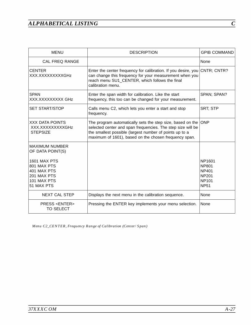
37XXXC OM A-27
ALPHABETICAL LISTING C
MENU DESCRIPTION GPIB COMMAND
CAL FREQ RANGE None
CENTERXXX.XXXXXXXXXGHz
Enter the center frequency for calibration. If you desire, youcan change this frequency for your measurement when youreach menu SU1_CENTER, which follows the finalcalibration menu.
CNTR; CNTR?
SPANXXX.XXXXXXXXX GHz
Enter the span width for calibration. Like the startfrequency, this too can be changed for your measurement.
SPAN; SPAN?
SET START/STOP Calls menu C2, which lets you enter a start and stopfrequency.
SRT; STP
XXX DATA POINTSXXX.XXXXXXXXXGHzSTEPSIZE
The program automatically sets the step size, based on theselected center and span frequencies. The step size will bethe smallest possible (largest number of points up to amaximum of 1601), based on the chosen frequency span.
ONP
MAXIMUM NUMBEROF DATA POINT(S)
1601 MAX PTS801 MAX PTS401 MAX PTS201 MAX PTS101 MAX PTS51 MAX PTS
NP1601NP801NP401NP201NP101NP51
NEXT CAL STEP Displays the next menu in the calibration sequence. None
PRESS <ENTER>TO SELECT
Pressing the ENTER key implements your menu selection. None
Menu C2_CENTER, Frequency Range of Calibration (Center/Span)
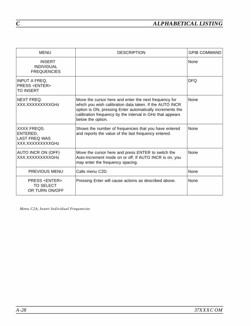
A-28 37XXXC OM
C ALPHABETICAL LISTING
MENU DESCRIPTION GPIB COMMAND
INSERTINDIVIDUAL
FREQUENCIES
None
INPUT A FREQ,PRESS <ENTER>TO INSERT
DFQ
NEXT FREQ.XXX.XXXXXXXXXGHz
Move the cursor here and enter the next frequency forwhich you wish calibration data taken. If the AUTO INCRoption is ON, pressing Enter automatically increments thecalibration frequency by the interval in GHz that appearsbelow the option.
None
XXXX FREQS.ENTERED,LAST FREQ WASXXX.XXXXXXXXXGHz
Shows the number of frequencies that you have enteredand reports the value of the last frequency entered.
None
AUTO INCR ON (OFF)XXX.XXXXXXXXXGHz
Move the cursor here and press ENTER to switch theAuto-Increment mode on or off. If AUTO INCR is on, youmay enter the frequency spacing.
None
PREVIOUS MENU Calls menu C2D. None
PRESS <ENTER>TO SELECT
OR TURN ON/OFF
Pressing Enter will cause actions as described above. None
Menu C2A, Insert Individual Frequencies
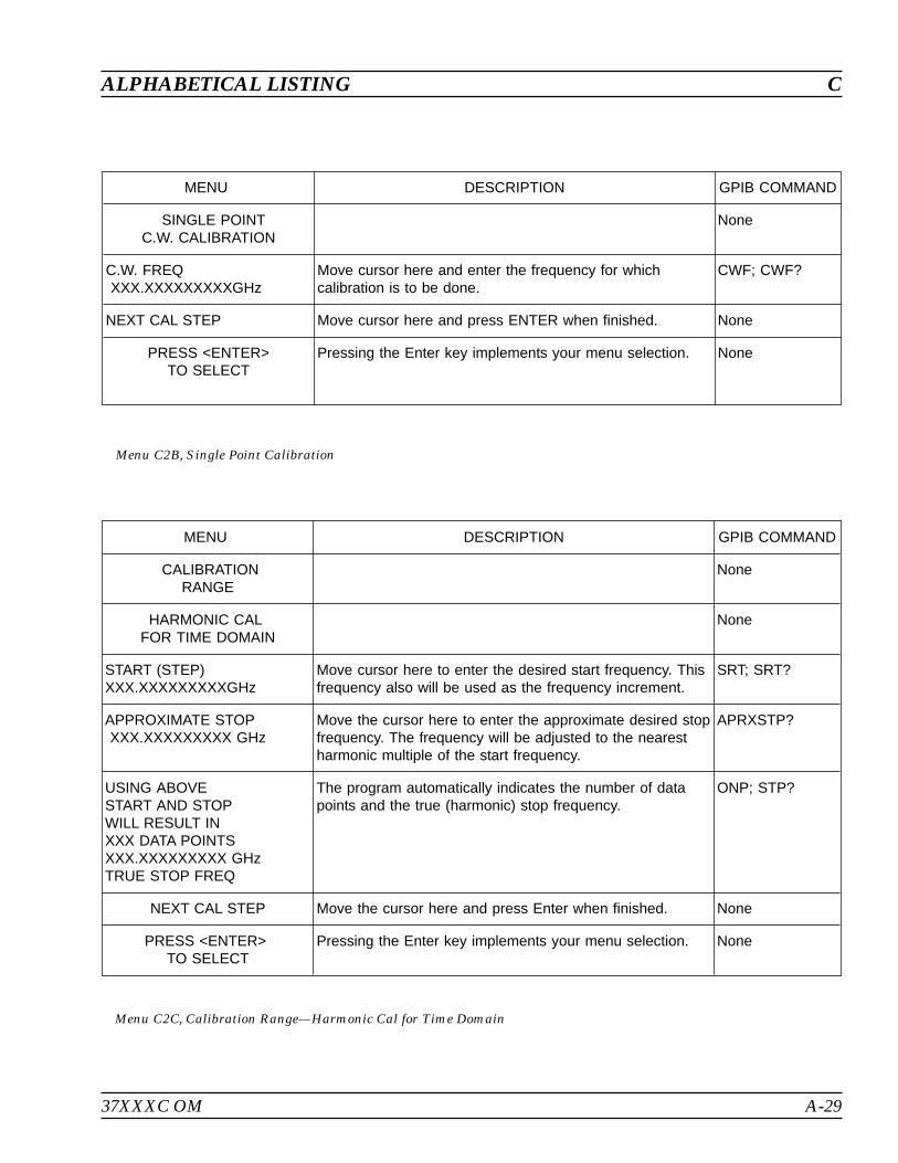
37XXXC OM A-29
ALPHABETICAL LISTING C
MENU DESCRIPTION GPIB COMMAND
CALIBRATIONRANGE
None
HARMONIC CALFOR TIME DOMAIN
None
START (STEP)XXX.XXXXXXXXXGHz
Move cursor here to enter the desired start frequency. Thisfrequency also will be used as the frequency increment.
SRT; SRT?
APPROXIMATE STOPXXX.XXXXXXXXX GHz
Move the cursor here to enter the approximate desired stopfrequency. The frequency will be adjusted to the nearestharmonic multiple of the start frequency.
APRXSTP?
USING ABOVESTART AND STOPWILL RESULT INXXX DATA POINTSXXX.XXXXXXXXX GHzTRUE STOP FREQ
The program automatically indicates the number of datapoints and the true (harmonic) stop frequency.
ONP; STP?
NEXT CAL STEP Move the cursor here and press Enter when finished. None
PRESS <ENTER>TO SELECT
Pressing the Enter key implements your menu selection. None
Menu C2C, Calibration Range—Harmonic Cal for Time Domain
MENU DESCRIPTION GPIB COMMAND
SINGLE POINTC.W. CALIBRATION
None
C.W. FREQXXX.XXXXXXXXXGHz
Move cursor here and enter the frequency for whichcalibration is to be done.
CWF; CWF?
NEXT CAL STEP Move cursor here and press ENTER when finished. None
PRESS <ENTER>TO SELECT
Pressing the Enter key implements your menu selection. None
Menu C2B, Single Point Calibration

A-30 37XXXC OM
C ALPHABETICAL LISTING
MENU DESCRIPTION GPIB COMMAND
DISCRETE FILLNone
INPUT START,INCR, POINTS,THEN SELECT“FILL RANGE”
This menu is used to create one or more ranges of discreteequally spaced frequency points for calibration.
None
START FREQXXX.XXXXXXXXX GHz
Enter the first frequency of the range. FRS; FRS?
INCREMENTXXX.XXXXXXXXX GHz
Enter the increment (step size) between one frequency andthe next.
FRI; FRI
NUMBER OF PTSXXXX POINT(S)
Enter the number of frequency points in the range. FRP; FRP?
STOP FREQXXX.XXXXXXXXX GHz
Enter the stop frequency, in GHz. None
FILL RANGE( XXXX ENTERED)
Moving the cursor here and pressing ENTER fills the rangeand shows the number of frequencies selected (inNUMBER OF PTS above).
FIL
INDIVIDUALFREQ INSERT
Calls menu C2A, which allows you to set the individualfrequencies.
DFQ
CLEAR ALL Clears all entries displayed above. FRC
FINISHEDNEXT CAL STEP
Calls menu C3, the next menu in the calibration sequence. None
PRESS <ENTER>TO SELECT
Pressing the Enter key implements your menu selection. None
Menu C2D, Fill Frequency Ranges
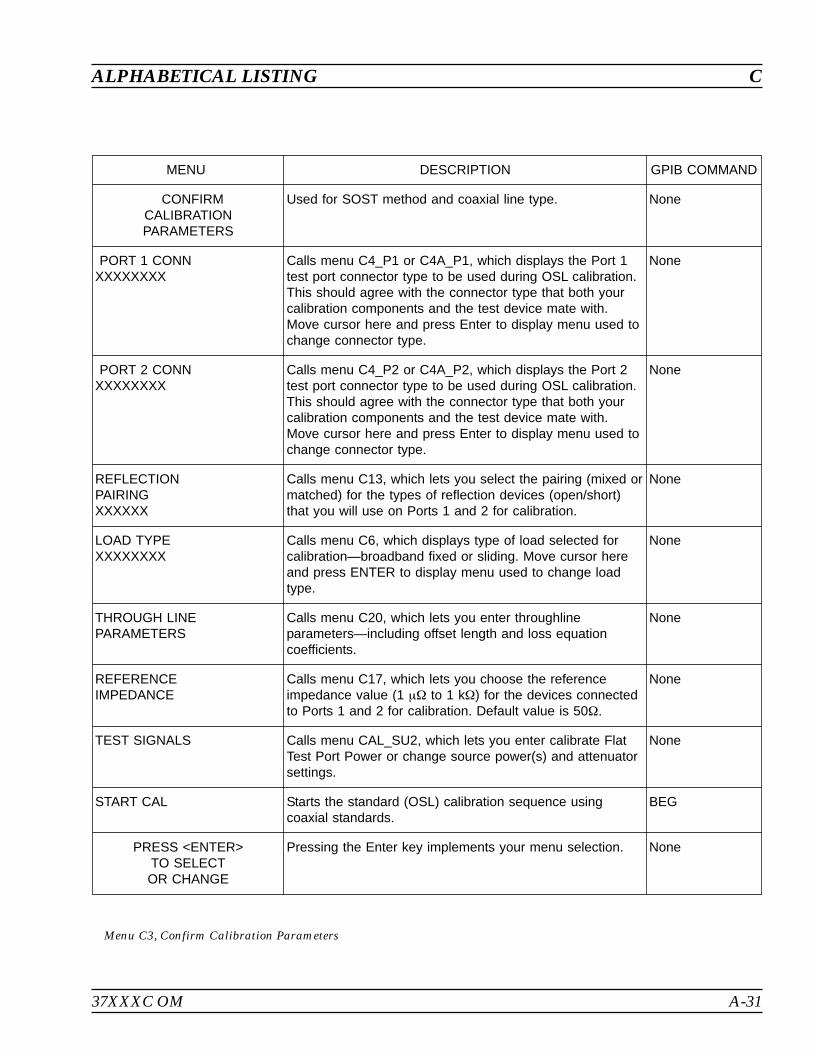
37XXXC OM A-31
ALPHABETICAL LISTING C
MENU DESCRIPTION GPIB COMMAND
CONFIRMCALIBRATIONPARAMETERS
Used for SOST method and coaxial line type. None
PORT 1 CONNXXXXXXXX
Calls menu C4_P1 or C4A_P1, which displays the Port 1test port connector type to be used during OSL calibration.This should agree with the connector type that both yourcalibration components and the test device mate with.Move cursor here and press Enter to display menu used tochange connector type.
None
PORT 2 CONNXXXXXXXX
Calls menu C4_P2 or C4A_P2, which displays the Port 2test port connector type to be used during OSL calibration.This should agree with the connector type that both yourcalibration components and the test device mate with.Move cursor here and press Enter to display menu used tochange connector type.
None
REFLECTIONPAIRINGXXXXXX
Calls menu C13, which lets you select the pairing (mixed ormatched) for the types of reflection devices (open/short)that you will use on Ports 1 and 2 for calibration.
None
LOAD TYPEXXXXXXXX
Calls menu C6, which displays type of load selected forcalibration—broadband fixed or sliding. Move cursor hereand press ENTER to display menu used to change loadtype.
None
THROUGH LINEPARAMETERS
Calls menu C20, which lets you enter throughlineparameters—including offset length and loss equationcoefficients.
None
REFERENCEIMPEDANCE
Calls menu C17, which lets you choose the referenceimpedance value (1 to 1 k) for the devices connectedto Ports 1 and 2 for calibration. Default value is 50.
None
TEST SIGNALS Calls menu CAL_SU2, which lets you enter calibrate FlatTest Port Power or change source power(s) and attenuatorsettings.
None
START CAL Starts the standard (OSL) calibration sequence usingcoaxial standards.
BEG
PRESS <ENTER>TO SELECTOR CHANGE
Pressing the Enter key implements your menu selection. None
Menu C3, Confirm Calibration Parameters
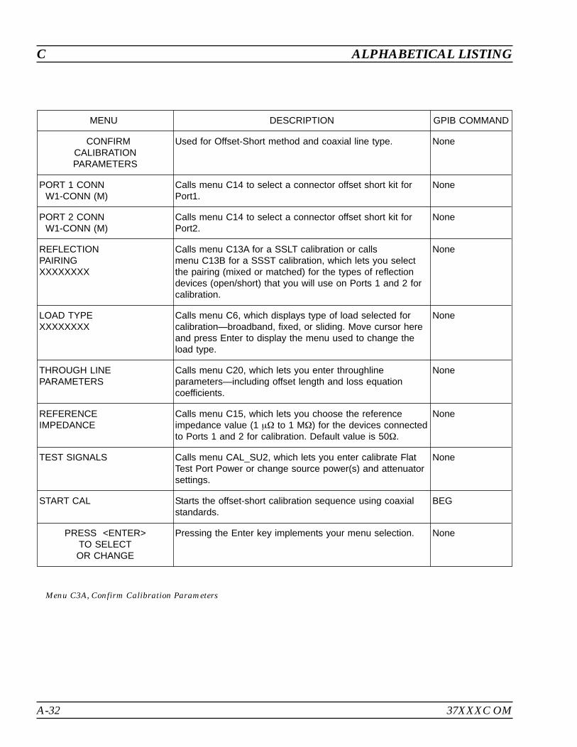
A-32 37XXXC OM
C ALPHABETICAL LISTING
MENU DESCRIPTION GPIB COMMAND
CONFIRMCALIBRATIONPARAMETERS
Used for Offset-Short method and coaxial line type. None
PORT 1 CONNW1-CONN (M)
Calls menu C14 to select a connector offset short kit forPort1.
None
PORT 2 CONNW1-CONN (M)
Calls menu C14 to select a connector offset short kit forPort2.
None
REFLECTIONPAIRINGXXXXXXXX
Calls menu C13A for a SSLT calibration or callsmenu C13B for a SSST calibration, which lets you selectthe pairing (mixed or matched) for the types of reflectiondevices (open/short) that you will use on Ports 1 and 2 forcalibration.
None
LOAD TYPEXXXXXXXX
Calls menu C6, which displays type of load selected forcalibration—broadband, fixed, or sliding. Move cursor hereand press Enter to display the menu used to change theload type.
None
THROUGH LINEPARAMETERS
Calls menu C20, which lets you enter throughlineparameters—including offset length and loss equationcoefficients.
None
REFERENCEIMPEDANCE
Calls menu C15, which lets you choose the referenceimpedance value (1 to 1 M) for the devices connectedto Ports 1 and 2 for calibration. Default value is 50.
None
TEST SIGNALS Calls menu CAL_SU2, which lets you enter calibrate FlatTest Port Power or change source power(s) and attenuatorsettings.
None
START CAL Starts the offset-short calibration sequence using coaxialstandards.
BEG
PRESS <ENTER>TO SELECTOR CHANGE
Pressing the Enter key implements your menu selection. None
Menu C3A, Confirm Calibration Parameters
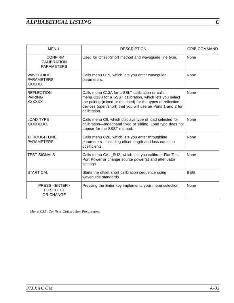
37XXXC OM A-33
ALPHABETICAL LISTING C
MENU DESCRIPTION GPIB COMMAND
CONFIRMCALIBRATIONPARAMETERS
Used for Offset-Short method and waveguide line type. None
WAVEGUIDEPARAMETERSXXXXXX
Calls menu C15, which lets you enter waveguideparameters.
None
REFLECTIONPAIRINGXXXXXX
Calls menu C13A for a SSLT calibration or callsmenu C13B for a SSST calibration, which lets you selectthe pairing (mixed or matched) for the types of reflectiondevices (open/short) that you will use on Ports 1 and 2 forcalibration.
None
LOAD TYPEXXXXXXXX
Calls menu C6, which displays type of load selected forcalibration—broadband fixed or sliding. Load type does notappear for the SSST method.
None
THROUGH LINEPARAMETERS
Calls menu C20, which lets you enter throughlineparameters—including offset length and loss equationcoefficients.
None
TEST SIGNALS Calls menu CAL_SU2, which lets you calibrate Flat TestPort Power or change source power(s) and attenuatorsettings.
None
START CAL Starts the offset-short calibration sequence usingwaveguide standards.
BEG
PRESS <ENTER>TO SELECTOR CHANGE
Pressing the Enter key implements your menu selection. None
Menu C3B, Confirm Calibration Parameters
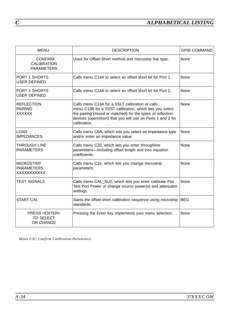
A-34 37XXXC OM
C ALPHABETICAL LISTING
MENU DESCRIPTION GPIB COMMAND
CONFIRMCALIBRATIONPARAMETERS
Used for Offset-Short method and microstrip line type. None
PORT 1 SHORTSUSER DEFINED
Calls menu C14A to select an offset short kit for Port 1. None
PORT 2 SHORTSUSER DEFINED
Calls menu C14A to select an offset short kit for Port 2. None
REFLECTIONPAIRINGXXXXXX
Calls menu C13A for a SSLT calibration or callsmenu C13B for a SSST calibration, which lets you selectthe pairing (mixed or matched) for the types of reflectiondevices (open/short) that you will use on Ports 1 and 2 forcalibration.
None
LOADIMPEDANCES
Calls menu C6A, which lets you select an impedance typeand/or enter an impedance value.
None
THROUGH LINEPARAMETERS
Calls menu C20, which lets you enter throughlineparameters—including offset length and loss equationcoefficients.
None
MICROSTRIPPARAMETERSXXXXXXXXXXX
Calls menu C16, which lets you change microstripparameters.
None
TEST SIGNALS Calls menu CAL_SU2, which lets you enter calibrate FlatTest Port Power or change source power(s) and attenuatorsettings.
None
START CAL Starts the offset-short calibration sequence using microstripstandards.
BEG
PRESS <ENTER>TO SELECTOR CHANGE
Pressing the Enter key implements your menu selection. None
Menu C3C, Confirm Calibration Parameters

37XXXC OM A-35
ALPHABETICAL LISTING C
MENU DESCRIPTION GPIB COMMAND
CONFIRMCALIBRATIONPARAMETERS
Used for SOLT method and microstrip line type. None
PORT 1 OPEN/SHORTXXXXXXXX
Calls menu C4B, which is used to select an offset short kitfor Port 1.
None
PORT 2 OPEN/SHORTXXXXXXXX
Calls menu C4B, which is used to select an offset short kitfor Port 2.
None
REFLECTIONPAIRINGXXXXXXXX
Calls menu C13A for a SSLT calibration or callsmenu C13B for a SSST calibration, which lets you selectthe pairing (mixed or matched) for the types of reflectiondevices (open/short) that you will use on Ports 1 and 2 forcalibration.
None
LOADIMPEDANCEXXXXXXXX
Calls menu C6A, which lets you select an impedance typeand/or enter an impedance value.
None
THROUGH LINEPARAMETERSXXXXXXXX
Calls menu C20, which lets you enter throughlineparameters—including offset length and loss equationcoefficients.
None
MICROSTRIPPARAMETERSXXXXXXXX
Calls menu C16, which lets you change microstripparameters.
None
TEST SIGNALS Calls menu CAL_SU2, which lets you enter calibrate FlatTest Port Power or change source power(s) and attenuatorsettings.
None
START CAL Starts the standard calibration sequence using microstripstandards.
BEG
PRESS <ENTER>TO SELECTOR CHANGE
Pressing the Enter key implements your menu selection. None
Menu C3D, Confirm Calibration Parameters
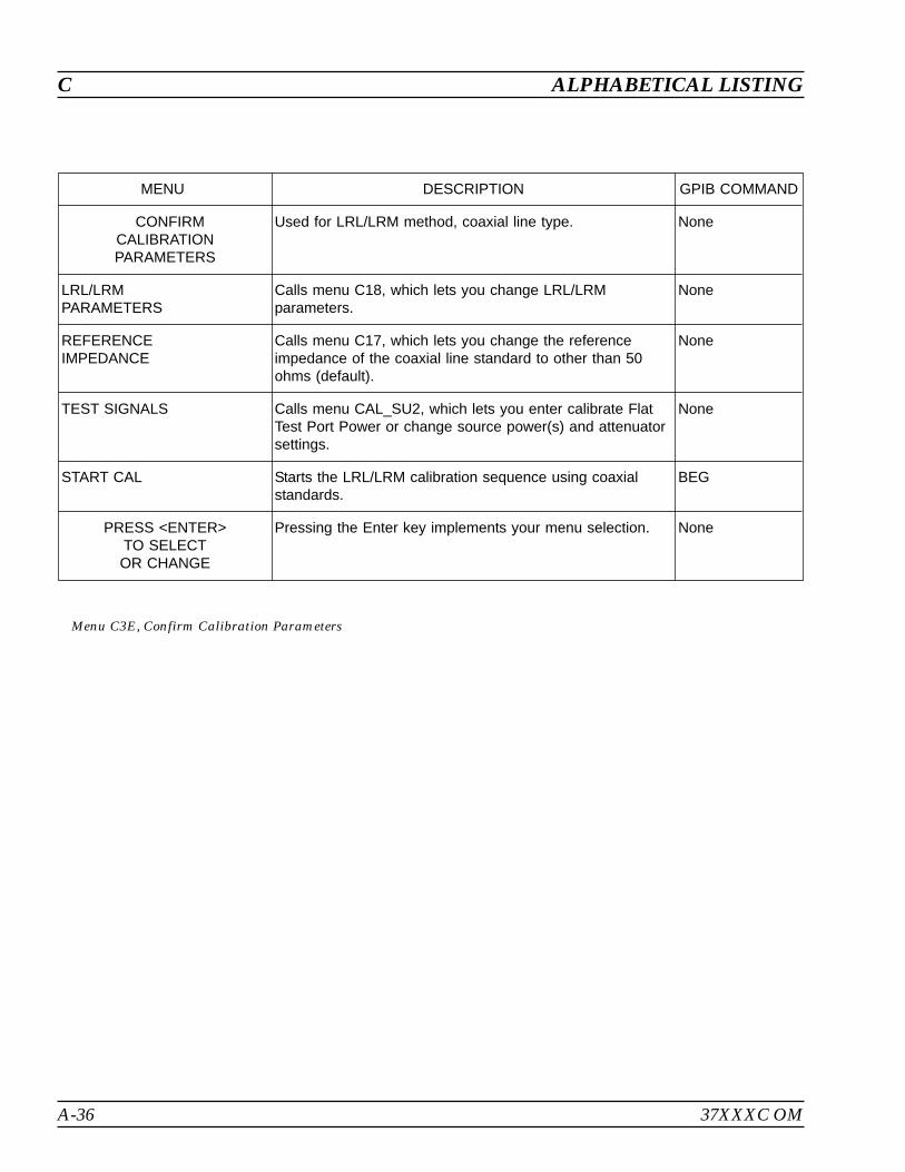
A-36 37XXXC OM
C ALPHABETICAL LISTING
MENU DESCRIPTION GPIB COMMAND
CONFIRMCALIBRATIONPARAMETERS
Used for LRL/LRM method, coaxial line type. None
LRL/LRMPARAMETERS
Calls menu C18, which lets you change LRL/LRMparameters.
None
REFERENCEIMPEDANCE
Calls menu C17, which lets you change the referenceimpedance of the coaxial line standard to other than 50ohms (default).
None
TEST SIGNALS Calls menu CAL_SU2, which lets you enter calibrate FlatTest Port Power or change source power(s) and attenuatorsettings.
None
START CAL Starts the LRL/LRM calibration sequence using coaxialstandards.
BEG
PRESS <ENTER>TO SELECTOR CHANGE
Pressing the Enter key implements your menu selection. None
Menu C3E, Confirm Calibration Parameters
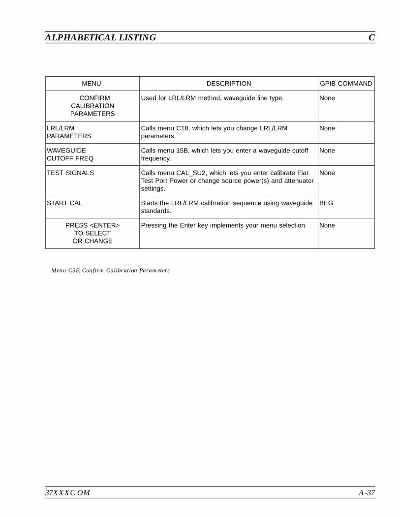
37XXXC OM A-37
ALPHABETICAL LISTING C
MENU DESCRIPTION GPIB COMMAND
CONFIRMCALIBRATIONPARAMETERS
Used for LRL/LRM method, waveguide line type. None
LRL/LRMPARAMETERS
Calls menu C18, which lets you change LRL/LRMparameters.
None
WAVEGUIDECUTOFF FREQ
Calls menu 15B, which lets you enter a waveguide cutofffrequency.
None
TEST SIGNALS Calls menu CAL_SU2, which lets you enter calibrate FlatTest Port Power or change source power(s) and attenuatorsettings.
None
START CAL Starts the LRL/LRM calibration sequence using waveguidestandards.
BEG
PRESS <ENTER>TO SELECTOR CHANGE
Pressing the Enter key implements your menu selection. None
Menu C3F, Confirm Calibration Parameters
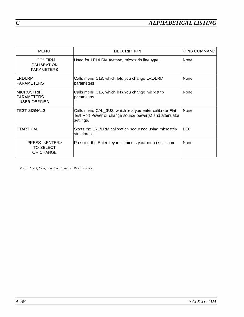
A-38 37XXXC OM
C ALPHABETICAL LISTING
MENU DESCRIPTION GPIB COMMAND
CONFIRMCALIBRATIONPARAMETERS
Used for LRL/LRM method, microstrip line type. None
LRL/LRMPARAMETERS
Calls menu C18, which lets you change LRL/LRMparameters.
None
MICROSTRIPPARAMETERS
USER DEFINED
Calls menu C16, which lets you change microstripparameters.
None
TEST SIGNALS Calls menu CAL_SU2, which lets you enter calibrate FlatTest Port Power or change source power(s) and attenuatorsettings.
None
START CAL Starts the LRL/LRM calibration sequence using microstripstandards.
BEG
PRESS <ENTER>TO SELECTOR CHANGE
Pressing the Enter key implements your menu selection. None
Menu C3G, Confirm Calibration Parameters
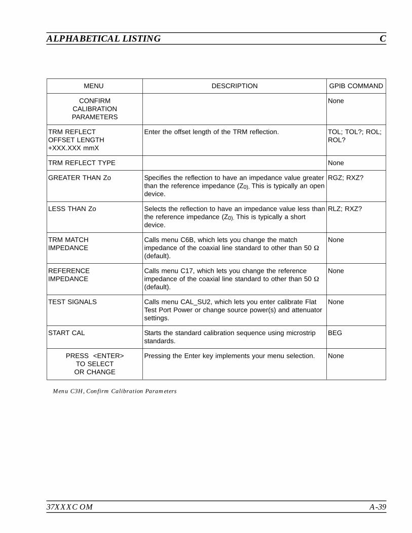
37XXXC OM A-39
ALPHABETICAL LISTING C
MENU DESCRIPTION GPIB COMMAND
CONFIRMCALIBRATIONPARAMETERS
None
TRM REFLECTOFFSET LENGTH+XXX.XXX mmX
Enter the offset length of the TRM reflection. TOL; TOL?; ROL;ROL?
TRM REFLECT TYPE None
GREATER THAN Zo Specifies the reflection to have an impedance value greaterthan the reference impedance (Z0). This is typically an opendevice.
RGZ; RXZ?
LESS THAN Zo Selects the reflection to have an impedance value less thanthe reference impedance (Z0). This is typically a shortdevice.
RLZ; RXZ?
TRM MATCHIMPEDANCE
Calls menu C6B, which lets you change the matchimpedance of the coaxial line standard to other than 50
(default).
None
REFERENCEIMPEDANCE
Calls menu C17, which lets you change the referenceimpedance of the coaxial line standard to other than 50
(default).
None
TEST SIGNALS Calls menu CAL_SU2, which lets you enter calibrate FlatTest Port Power or change source power(s) and attenuatorsettings.
None
START CAL Starts the standard calibration sequence using microstripstandards.
BEG
PRESS <ENTER>TO SELECTOR CHANGE
Pressing the Enter key implements your menu selection. None
Menu C3H, Confirm Calibration Parameters

A-40 37XXXC OM
C ALPHABETICAL LISTING
MENU DESCRIPTION GPIB COMMAND
CONFIRMCALIBRATIONPARAMETERS
None
TRM REFLECTOFFSET LENGTH+XXX.XXX mmX
Enter the offset length of the TRM reflection. TOL; TOL?; ROL;ROL?
TRM MATCHIMPEDANCE
Calls menu C6B, which lets you change the matchimpedance of the coaxial line standard to other than 50
(default).
None
WAVEGUIDECUTOFF FREQ
Calls menu 15B, which lets you enter a waveguide cutofffrequency.
None
TEST SIGNALS Calls menu CAL_SU2, which lets you enter calibrate FlatTest Port Power or change source power(s) and attenuatorsettings.
None
START CAL Starts the standard calibration sequence using microstripstandards.
BEG
PRESS <ENTER>TO SELECTOR CHANGE
Pressing the Enter key implements your menu selection. None
Menu C3I, ConfirmCalibration Parameter 2
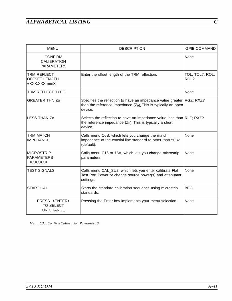
37XXXC OM A-41
ALPHABETICAL LISTING C
MENU DESCRIPTION GPIB COMMAND
CONFIRMCALIBRATIONPARAMETERS
None
TRM REFLECTOFFSET LENGTH+XXX.XXX mmX
Enter the offset length of the TRM reflection. TOL; TOL?; ROL;ROL?
TRM REFLECT TYPE None
GREATER THN Zo Specifies the reflection to have an impedance value greaterthan the reference impedance (Z0). This is typically an opendevice.
RGZ; RXZ?
LESS THAN Zo Selects the reflection to have an impedance value less thanthe reference impedance (Z0). This is typically a shortdevice.
RLZ; RXZ?
TRM MATCHIMPEDANCE
Calls menu C6B, which lets you change the matchimpedance of the coaxial line standard to other than 50
(default).
None
MICROSTRIPPARAMETERS
XXXXXXX
Calls menu C16 or 16A, which lets you change microstripparameters.
None
TEST SIGNALS Calls menu CAL_SU2, which lets you enter calibrate FlatTest Port Power or change source power(s) and attenuatorsettings.
None
START CAL Starts the standard calibration sequence using microstripstandards.
BEG
PRESS <ENTER>TO SELECTOR CHANGE
Pressing the Enter key implements your menu selection. None
Menu C3J, ConfirmCalibration Parameter 3
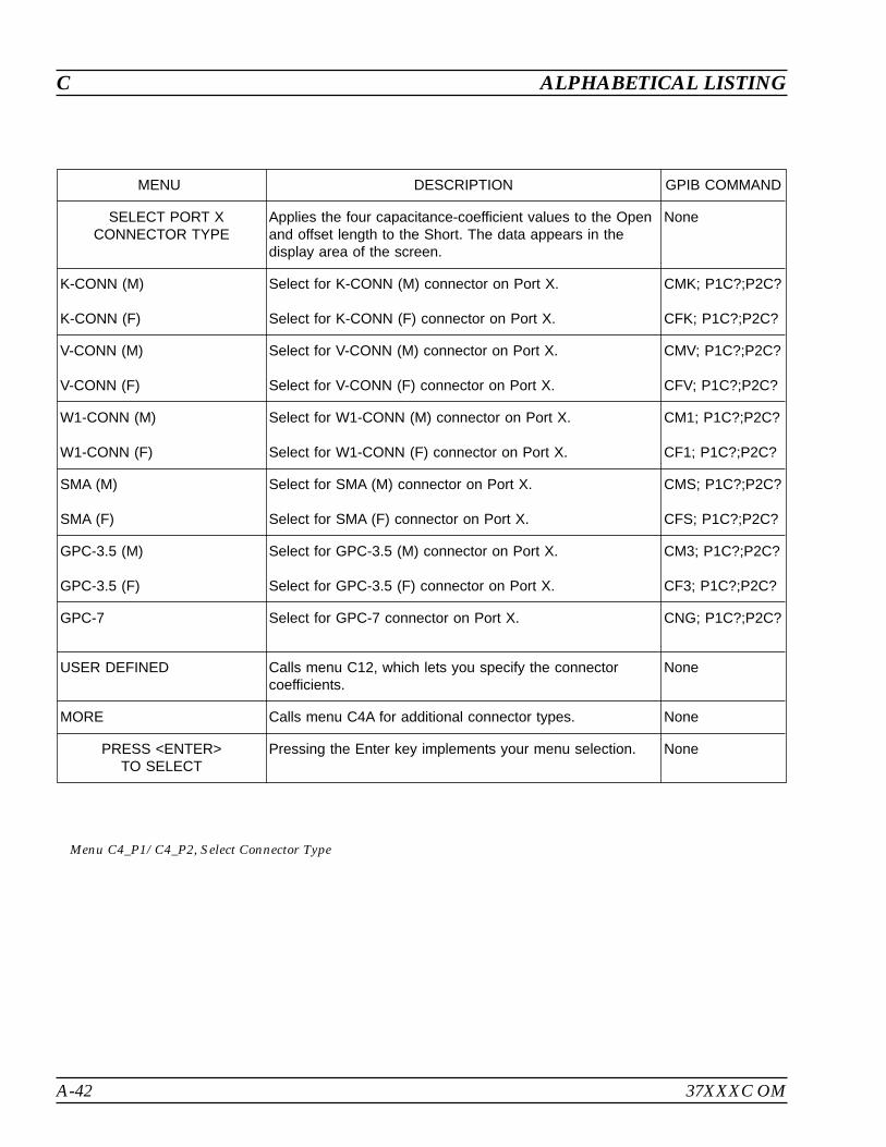
A-42 37XXXC OM
C ALPHABETICAL LISTING
MENU DESCRIPTION GPIB COMMAND
SELECT PORT XCONNECTOR TYPE
Applies the four capacitance-coefficient values to the Openand offset length to the Short. The data appears in thedisplay area of the screen.
None
K-CONN (M)
K-CONN (F)
Select for K-CONN (M) connector on Port X.
Select for K-CONN (F) connector on Port X.
CMK; P1C?;P2C?
CFK; P1C?;P2C?
V-CONN (M)
V-CONN (F)
Select for V-CONN (M) connector on Port X.
Select for V-CONN (F) connector on Port X.
CMV; P1C?;P2C?
CFV; P1C?;P2C?
W1-CONN (M)
W1-CONN (F)
Select for W1-CONN (M) connector on Port X.
Select for W1-CONN (F) connector on Port X.
CM1; P1C?;P2C?
CF1; P1C?;P2C?
SMA (M)
SMA (F)
Select for SMA (M) connector on Port X.
Select for SMA (F) connector on Port X.
CMS; P1C?;P2C?
CFS; P1C?;P2C?
GPC-3.5 (M)
GPC-3.5 (F)
Select for GPC-3.5 (M) connector on Port X.
Select for GPC-3.5 (F) connector on Port X.
CM3; P1C?;P2C?
CF3; P1C?;P2C?
GPC-7 Select for GPC-7 connector on Port X. CNG; P1C?;P2C?
USER DEFINED Calls menu C12, which lets you specify the connectorcoefficients.
None
MORE Calls menu C4A for additional connector types. None
PRESS <ENTER>TO SELECT
Pressing the Enter key implements your menu selection. None
Menu C4_P1/C4_P2, Select Connector Type
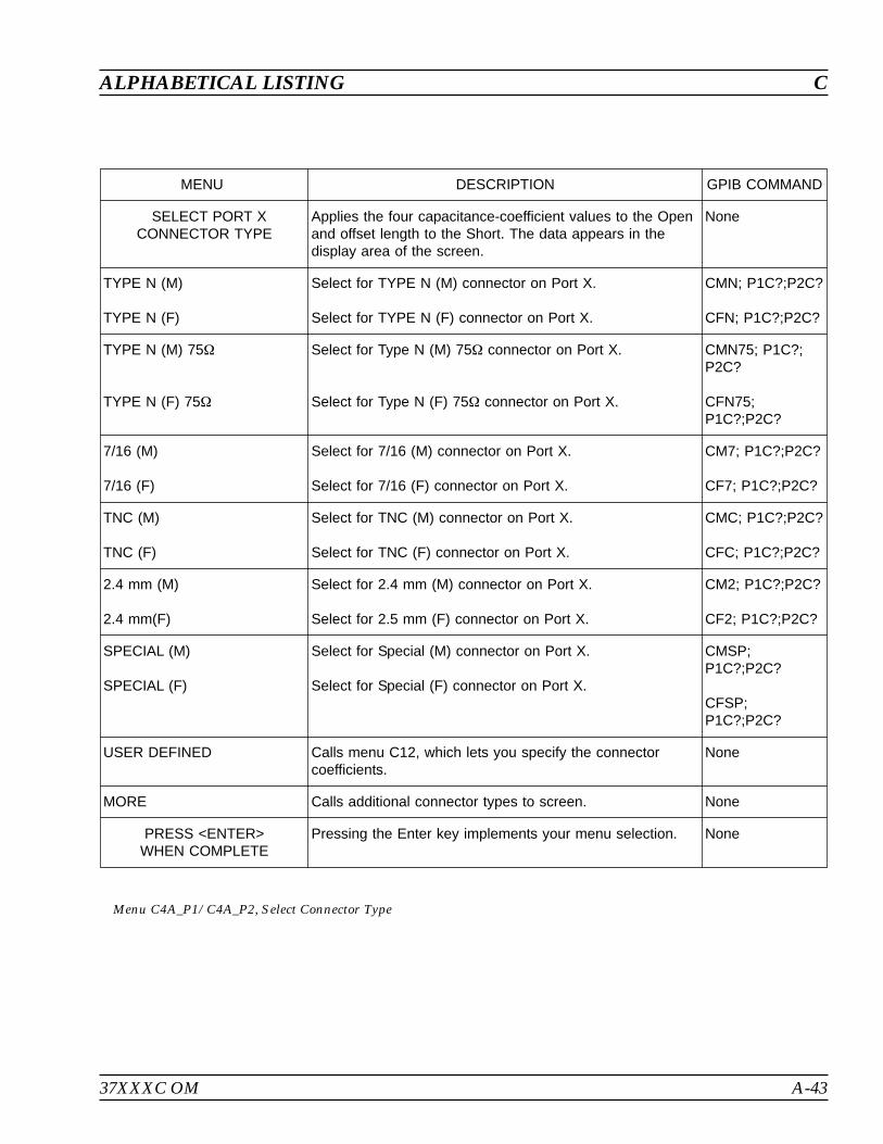
37XXXC OM A-43
ALPHABETICAL LISTING C
MENU DESCRIPTION GPIB COMMAND
SELECT PORT XCONNECTOR TYPE
Applies the four capacitance-coefficient values to the Openand offset length to the Short. The data appears in thedisplay area of the screen.
None
TYPE N (M)
TYPE N (F)
Select for TYPE N (M) connector on Port X.
Select for TYPE N (F) connector on Port X.
CMN; P1C?;P2C?
CFN; P1C?;P2C?
TYPE N (M) 75
TYPE N (F) 75
Select for Type N (M) 75 connector on Port X.
Select for Type N (F) 75 connector on Port X.
CMN75; P1C?;P2C?
CFN75;P1C?;P2C?
7/16 (M)
7/16 (F)
Select for 7/16 (M) connector on Port X.
Select for 7/16 (F) connector on Port X.
CM7; P1C?;P2C?
CF7; P1C?;P2C?
TNC (M)
TNC (F)
Select for TNC (M) connector on Port X.
Select for TNC (F) connector on Port X.
CMC; P1C?;P2C?
CFC; P1C?;P2C?
2.4 mm (M)
2.4 mm(F)
Select for 2.4 mm (M) connector on Port X.
Select for 2.5 mm (F) connector on Port X.
CM2; P1C?;P2C?
CF2; P1C?;P2C?
SPECIAL (M)
SPECIAL (F)
Select for Special (M) connector on Port X.
Select for Special (F) connector on Port X.
CMSP;P1C?;P2C?
CFSP;P1C?;P2C?
USER DEFINED Calls menu C12, which lets you specify the connectorcoefficients.
None
MORE Calls additional connector types to screen. None
PRESS <ENTER>WHEN COMPLETE
Pressing the Enter key implements your menu selection. None
Menu C4A_P1/C4A_P2, Select Connector Type
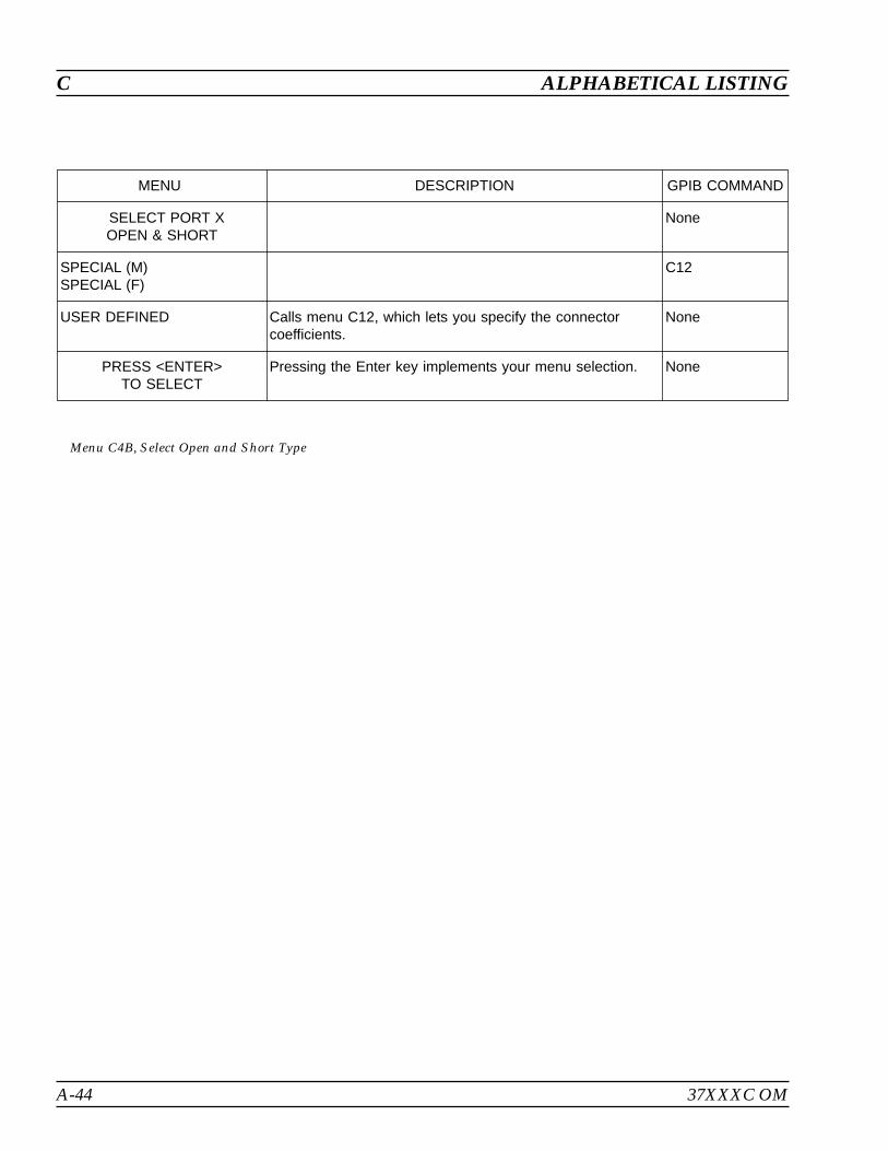
A-44 37XXXC OM
C ALPHABETICAL LISTING
MENU DESCRIPTION GPIB COMMAND
SELECT PORT XOPEN & SHORT
None
SPECIAL (M)SPECIAL (F)
C12
USER DEFINED Calls menu C12, which lets you specify the connectorcoefficients.
None
PRESS <ENTER>TO SELECT
Pressing the Enter key implements your menu selection. None
Menu C4B, Select Open and Short Type

37XXXC OM A-45
ALPHABETICAL LISTING C
MENU DESCRIPTION GPIB COMMAND
SELECTCALIBRATION TYPE
None
FULL 12-TERM Select calibration using all 12 error terms EDF, ESF, ERF,ETF, ELF, (EXF), EDR, ESR, ERR, ETR, FLR, (EXR).
C12
1 PATH2 PORT
Calls menu C5A, which lets select a correction for forward-or reverse-direction error terms.
None
TRANSMISSIONFREQUENCYRESPONSE
Calls menu C5B, which lets select a correction forfrequency response error terms.
None
REFLECTIONONLY
Calls menu C5C, which lets select a correction forreflection-only error terms.
None
PRESS <ENTER>TO SELECT
Pressing the Enter key implements your menu selection. None
Menu C5, Select Calibration Type
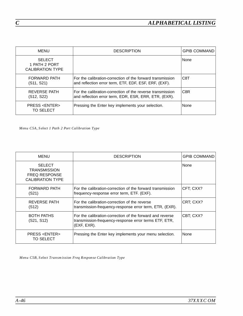
A-46 37XXXC OM
C ALPHABETICAL LISTING
MENU DESCRIPTION GPIB COMMAND
SELECT1 PATH 2 PORT
CALIBRATION TYPE
None
FORWARD PATH(S11, S21)
For the calibration-correction of the forward transmissionand reflection error term, ETF, EDF, ESF, ERF, (EXF).
C8T
REVERSE PATH(S12, S22)
For the calibration-correction of the reverse transmissionand reflection error term, EDR, ESR, ERR, ETR, (EXR).
C8R
PRESS <ENTER>TO SELECT
Pressing the Enter key implements your selection. None
Menu C5A, Select 1 Path 2 Port Calibration Type
MENU DESCRIPTION GPIB COMMAND
SELECTTRANSMISSION
FREQ RESPONSECALIBRATION TYPE
None
FORWARD PATH(S21)
For the calibration-correction of the forward transmissionfrequency-response error term, ETF. (EXF).
CFT; CXX?
REVERSE PATH(S12)
For the calibration-correction of the reversetransmission-frequency-response error term, ETR, (EXR).
CRT; CXX?
BOTH PATHS(S21, S12)
For the calibration-correction of the forward and reversetransmission-frequency-response error terms ETF, ETR,(EXF, EXR).
CBT; CXX?
PRESS <ENTER>TO SELECT
Pressing the Enter key implements your menu selection. None
Menu C5B, Select Transmission Freq Response Calibration Type
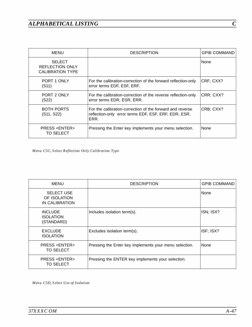
37XXXC OM A-47
ALPHABETICAL LISTING C
MENU DESCRIPTION GPIB COMMAND
SELECTREFLECTION ONLYCALIBRATION TYPE
None
PORT 1 ONLY(S11)
For the calibration-correction of the forward reflection-onlyerror terms EDF, ESF, ERF.
CRF; CXX?
PORT 2 ONLY(S22)
For the calibration-correction of the reverse reflection-onlyerror terms EDR, ESR, ERR.
CRR; CXX?
BOTH PORTS(S11, S22)
For the calibration-correction of the forward and reversereflection-only error terms EDF, ESF, ERF, EDR, ESR,ERR.
CRB; CXX?
PRESS <ENTER>TO SELECT
Pressing the Enter key implements your menu selection. None
Menu C5C, Select Reflection Only Calibration Type
MENU DESCRIPTION GPIB COMMAND
SELECT USEOF ISOLATION
IN CALIBRATION
None
INCLUDEISOLATION(STANDARD)
Includes isolation term(s). ISN; ISX?
EXCLUDEISOLATION
Excludes isolation term(s). ISF; ISX?
PRESS <ENTER>TO SELECT
Pressing the Enter key implements your menu selection. None
PRESS <ENTER>TO SELECT
Pressing the ENTER key implements your selection.
Menu C5D, Select Use of Isolation
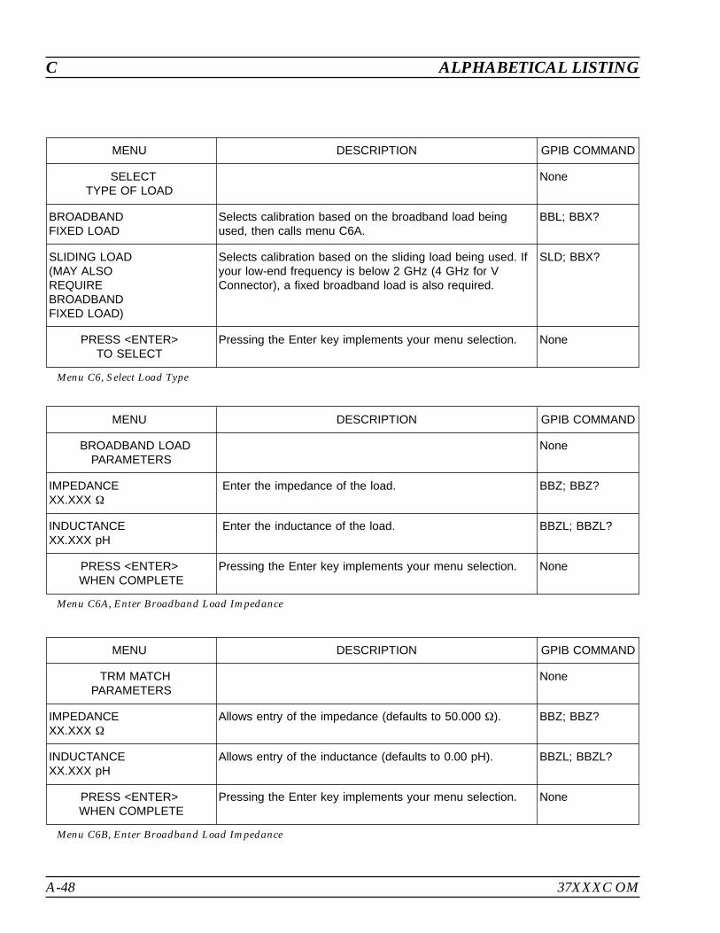
A-48 37XXXC OM
C ALPHABETICAL LISTING
MENU DESCRIPTION GPIB COMMAND
SELECTTYPE OF LOAD
None
BROADBANDFIXED LOAD
Selects calibration based on the broadband load beingused, then calls menu C6A.
BBL; BBX?
SLIDING LOAD(MAY ALSOREQUIREBROADBANDFIXED LOAD)
Selects calibration based on the sliding load being used. Ifyour low-end frequency is below 2 GHz (4 GHz for VConnector), a fixed broadband load is also required.
SLD; BBX?
PRESS <ENTER>TO SELECT
Pressing the Enter key implements your menu selection. None
Menu C6, Select Load Type
MENU DESCRIPTION GPIB COMMAND
BROADBAND LOADPARAMETERS
None
IMPEDANCEXX.XXX
Enter the impedance of the load. BBZ; BBZ?
INDUCTANCEXX.XXX pH
Enter the inductance of the load. BBZL; BBZL?
PRESS <ENTER>WHEN COMPLETE
Pressing the Enter key implements your menu selection. None
Menu C6A, Enter Broadband Load Impedance
MENU DESCRIPTION GPIB COMMAND
TRM MATCHPARAMETERS
None
IMPEDANCEXX.XXX
Allows entry of the impedance (defaults to 50.000 ). BBZ; BBZ?
INDUCTANCEXX.XXX pH
Allows entry of the inductance (defaults to 0.00 pH). BBZL; BBZL?
PRESS <ENTER>WHEN COMPLETE
Pressing the Enter key implements your menu selection. None
Menu C6B, Enter Broadband Load Impedance
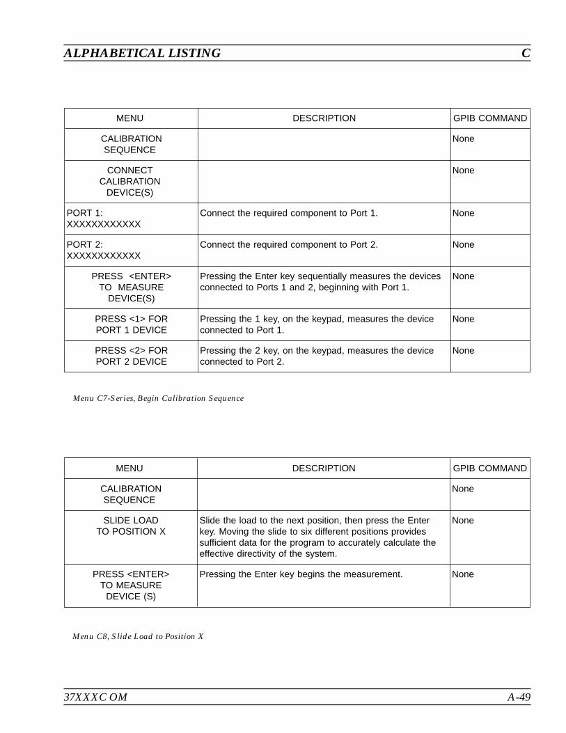
37XXXC OM A-49
ALPHABETICAL LISTING C
MENU DESCRIPTION GPIB COMMAND
CALIBRATIONSEQUENCE
None
CONNECTCALIBRATION
DEVICE(S)
None
PORT 1:XXXXXXXXXXXX
Connect the required component to Port 1. None
PORT 2:XXXXXXXXXXXX
Connect the required component to Port 2. None
PRESS <ENTER>TO MEASURE
DEVICE(S)
Pressing the Enter key sequentially measures the devicesconnected to Ports 1 and 2, beginning with Port 1.
None
PRESS <1> FORPORT 1 DEVICE
Pressing the 1 key, on the keypad, measures the deviceconnected to Port 1.
None
PRESS <2> FORPORT 2 DEVICE
Pressing the 2 key, on the keypad, measures the deviceconnected to Port 2.
None
Menu C7-Series, Begin Calibration Sequence
MENU DESCRIPTION GPIB COMMAND
CALIBRATIONSEQUENCE
None
SLIDE LOADTO POSITION X
Slide the load to the next position, then press the Enterkey. Moving the slide to six different positions providessufficient data for the program to accurately calculate theeffective directivity of the system.
None
PRESS <ENTER>TO MEASURE
DEVICE (S)
Pressing the Enter key begins the measurement. None
Menu C8, Slide Load to Position X
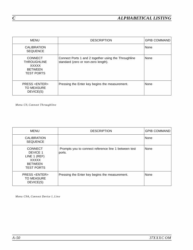
A-50 37XXXC OM
C ALPHABETICAL LISTING
MENU DESCRIPTION GPIB COMMAND
CALIBRATIONSEQUENCE
None
CONNECTDEVICE 1
LINE 1 (REF)XXXXX
BETWEENTEST PORTS
Prompts you to connect reference line 1 between testports.
None
PRESS <ENTER>TO MEASURE
DEVICE(S)
Pressing the Enter key begins the measurement. None
Menu C9A, Connect Device 1, Line
MENU DESCRIPTION GPIB COMMAND
CALIBRATIONSEQUENCE
None
CONNECTTHROUGHLINE
XXXXXBETWEEN
TEST PORTS
Connect Ports 1 and 2 together using the Throughlinestandard (zero or non-zero length).
None
PRESS <ENTER>TO MEASURE
DEVICE(S)
Pressing the Enter key begins the measurement. None
Menu C9, Connect Throughline
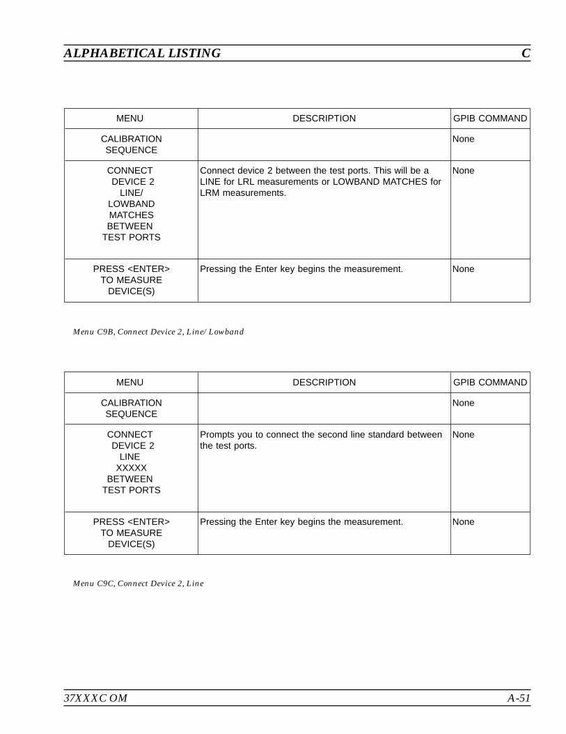
37XXXC OM A-51
ALPHABETICAL LISTING C
MENU DESCRIPTION GPIB COMMAND
CALIBRATIONSEQUENCE
None
CONNECTDEVICE 2
LINEXXXXX
BETWEENTEST PORTS
Prompts you to connect the second line standard betweenthe test ports.
None
PRESS <ENTER>TO MEASURE
DEVICE(S)
Pressing the Enter key begins the measurement. None
Menu C9C, Connect Device 2, Line
MENU DESCRIPTION GPIB COMMAND
CALIBRATIONSEQUENCE
None
CONNECTDEVICE 2
LINE/LOWBANDMATCHESBETWEEN
TEST PORTS
Connect device 2 between the test ports. This will be aLINE for LRL measurements or LOWBAND MATCHES forLRM measurements.
None
PRESS <ENTER>TO MEASURE
DEVICE(S)
Pressing the Enter key begins the measurement. None
Menu C9B, Connect Device 2, Line/Lowband

A-52 37XXXC OM
C ALPHABETICAL LISTING
MENU DESCRIPTION GPIB COMMAND
BEGIN CALIBRATION None
KEEP EXISTINGCAL DATA
Keep existing calibration data. KEC
REPEATPREVIOUS CAL
Repeats the previous calibration. RPC
AUTOCAL Calls menu ACAL, which lets you choose AutoCal settings. None
CAL METHODXXXXXXX
Displays the calibration method that you haveselected—standard,offset short or LRL/LRM.
CMX?
TRANSMISSIONLINE TYPE:XXXXXXXX
Indicates type of transmission line currently selected, e. g.coaxial,waveguide, microstrip.
LTX?
CHANGE CALMETHOD ANDLINE TYPE
Calls menu C11A, which allows you to change calibrationmethod and transmission line type.
None
NEXT CAL STEP Selects the next calibration step. None
PRESS <ENTER>TO SELECT
Pressing the Enter key implements your menu selection. None
Menu C11, Begin Calibration
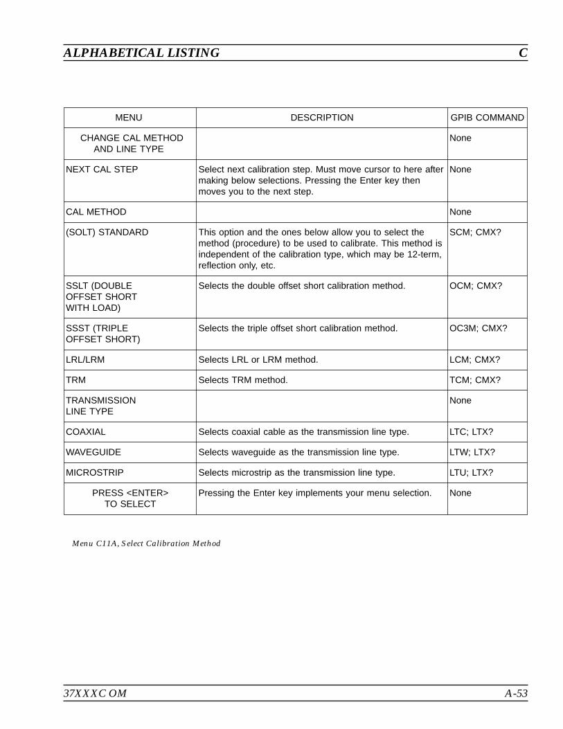
37XXXC OM A-53
ALPHABETICAL LISTING C
MENU DESCRIPTION GPIB COMMAND
CHANGE CAL METHODAND LINE TYPE
None
NEXT CAL STEP Select next calibration step. Must move cursor to here aftermaking below selections. Pressing the Enter key thenmoves you to the next step.
None
CAL METHOD None
(SOLT) STANDARD This option and the ones below allow you to select themethod (procedure) to be used to calibrate. This method isindependent of the calibration type, which may be 12-term,reflection only, etc.
SCM; CMX?
SSLT (DOUBLEOFFSET SHORTWITH LOAD)
Selects the double offset short calibration method. OCM; CMX?
SSST (TRIPLEOFFSET SHORT)
Selects the triple offset short calibration method. OC3M; CMX?
LRL/LRM Selects LRL or LRM method. LCM; CMX?
TRM Selects TRM method. TCM; CMX?
TRANSMISSIONLINE TYPE
None
COAXIAL Selects coaxial cable as the transmission line type. LTC; LTX?
WAVEGUIDE Selects waveguide as the transmission line type. LTW; LTX?
MICROSTRIP Selects microstrip as the transmission line type. LTU; LTX?
PRESS <ENTER>TO SELECT
Pressing the Enter key implements your menu selection. None
Menu C11A, Select Calibration Method
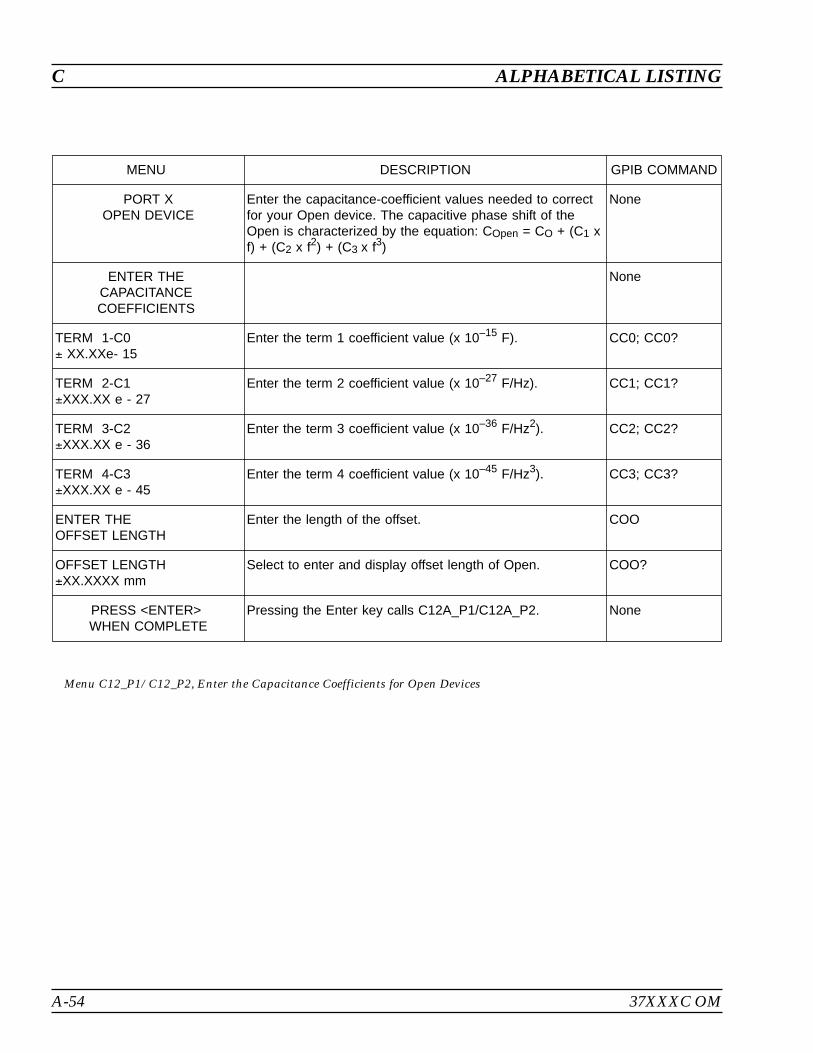
A-54 37XXXC OM
C ALPHABETICAL LISTING
MENU DESCRIPTION GPIB COMMAND
PORT XOPEN DEVICE
Enter the capacitance-coefficient values needed to correctfor your Open device. The capacitive phase shift of theOpen is characterized by the equation: COpen = CO + (C1 xf) + (C2 x f2) + (C3 x f3)
None
ENTER THECAPACITANCECOEFFICIENTS
None
TERM 1-C0 XX.XXe- 15
Enter the term 1 coefficient value (x 10–15 F). CC0; CC0?
TERM 2-C1XXX.XX e - 27
Enter the term 2 coefficient value (x 10–27 F/Hz). CC1; CC1?
TERM 3-C2XXX.XX e - 36
Enter the term 3 coefficient value (x 10–36 F/Hz2). CC2; CC2?
TERM 4-C3XXX.XX e - 45
Enter the term 4 coefficient value (x 10–45 F/Hz3). CC3; CC3?
ENTER THEOFFSET LENGTH
Enter the length of the offset. COO
OFFSET LENGTHXX.XXXX mm
Select to enter and display offset length of Open. COO?
PRESS <ENTER>WHEN COMPLETE
Pressing the Enter key calls C12A_P1/C12A_P2. None
Menu C12_P1/C12_P2, Enter the Capacitance Coefficients for Open Devices
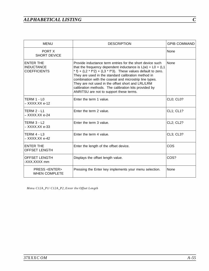
37XXXC OM A-55
ALPHABETICAL LISTING C
MENU DESCRIPTION GPIB COMMAND
PORT XSHORT DEVICE
None
ENTER THEINDUCTANCECOEFFICIENTS
Provide inductance term entries for the short device suchthat the frequency dependent inductance is L(w) = L0 + (L1* f) + (L2 * f^2) + (L3 * f^3). These values default to zero.They are used in the standard calibration method incombination with the coaxial and microstrip line types.They are not used in the offset short and LRL/LRMcalibration methods. The calibration kits provided byANRITSU are not to support these terms.
None
TERM 1 - L0 XXXX.XX e-12
Enter the term 1 value. CL0; CL0?
TERM 2 - L1 XXXX.XX e-24
Enter the term 2 value. CL1; CL1?
TERM 3 - L2 XXXX.XX e-33
Enter the term 3 value. CL2; CL2?
TERM 4 - L3 XXXX.XX e-42
Enter the term 4 value. CL3; CL3?
ENTER THEOFFSET LENGTH
Enter the length of the offset device. COS
OFFSET LENGTH-XXX.XXXX mm
Displays the offset length value. COS?
PRESS <ENTER>WHEN COMPLETE
Pressing the Enter key implements your menu selection. None
Menu C12A_P1/C12A_P2, Enter the Offset Length
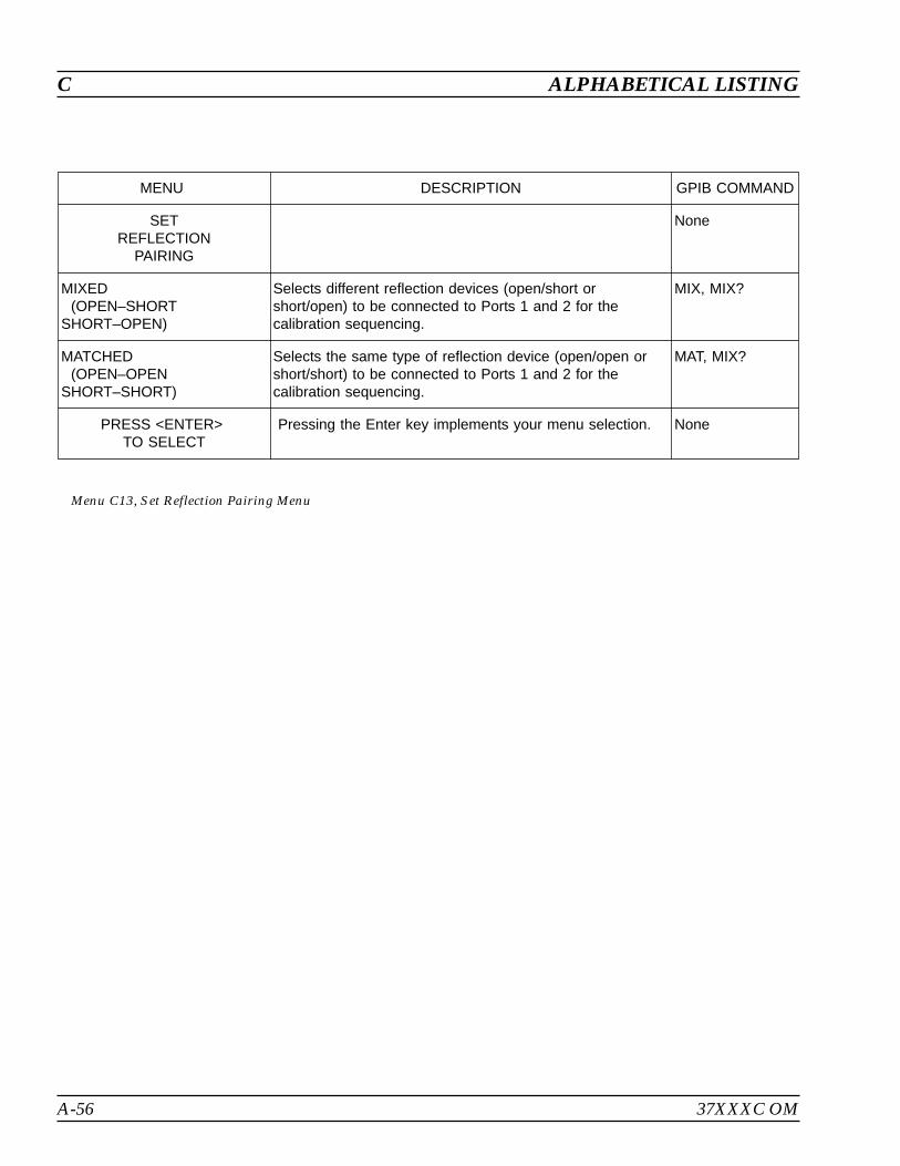
A-56 37XXXC OM
C ALPHABETICAL LISTING
MENU DESCRIPTION GPIB COMMAND
SETREFLECTION
PAIRING
None
MIXED(OPEN–SHORT
SHORT–OPEN)
Selects different reflection devices (open/short orshort/open) to be connected to Ports 1 and 2 for thecalibration sequencing.
MIX, MIX?
MATCHED(OPEN–OPEN
SHORT–SHORT)
Selects the same type of reflection device (open/open orshort/short) to be connected to Ports 1 and 2 for thecalibration sequencing.
MAT, MIX?
PRESS <ENTER>TO SELECT
Pressing the Enter key implements your menu selection. None
Menu C13, Set Reflection Pairing Menu

37XXXC OM A-57
ALPHABETICAL LISTING C
MENU DESCRIPTION GPIB COMMAND
SELECTREFLECTION
PAIRING
None
MIXED(SHORT1-SHORT2,SHORT2-SHORT1)
Selects mixed reflection pairing. MIX
MATCHED(SHORT1-SHORT1,SHORT2-SHORT2)
Selects matched reflection pairing. MAT
PRESS <ENTER>TO SELECT
Pressing the Enter key implements your menu selection. None
Menu C13A, Set Reflection Pairing Menu
MENU DESCRIPTION GPIB COMMAND
SELECTREFLECTION
PAIRING
None
MIXED(SHORT1-SHORT2,SHORT2-SHORT3,SHORT3-SHORT1)
Selects mixed reflection pairing. MIX
MATCHED(SHORT1-SHORT1,SHORT2-SHORT2,SHORT3-SHORT3)
Selects matched reflection pairing. MAT
PRESS <ENTER>TO SELECT
Pressing the Enter key implements your menu selection. None
Menu C13B, Set Reflection Pairing Menu

A-58 37XXXC OM
C ALPHABETICAL LISTING
MENU DESCRIPTION GPIB COMMAND
SELECT PORT XOFFSET SHORT
CONNECOTR TYPE
Used with the coaxial line type. None
W1-CONN (M)W1-CONN (F)
Selects W1(M) connector (kit) type on Port X.Selects W1 (F) connector (kit) type on Port X.
CM1CF1P1C?; P2C?
SPECIAL A (M)SPECIAL A (F)
Selects Special A (M) connector (kit) type on Port X.Selects Special A (F) connector (kit) type on Port X.
CMSPACFSPAP1C?; P2C?
SPECIAL B (M)SPECIAL B (F)
Selects Special B (M) connector (kit) type on Port X.Selects Special B (F) connector (kit) type on Port X.
CMSPBCFSPBP1C?; P2C?
SPECIAL C (M)SPECIAL C (F)
Selects Special C (M) connector (kit) type on Port X.Selects Special C (F) connector (kit) type on Port X.
CMSPCCFSPCP1C?; P2C?
USER DEFINED Calls menu C21A, C21B, then C21C, which allows you todefine the inductance coefficients and offset length values.
PRESS <ENTER>WHEN COMPLETE
Pressing the Enter key implements your menu selection. None
Menu C14, Select Port X Offset Short Connecotr Type
MENU DESCRIPTION GPIB COMMAND
SELECT PORT XOFFSET SHORT
Used with the microstrip line type. None
SPECIAL A (M)SPECIAL A (F)
Selects Special A (M) connector (kit) type on Port X.Selects Special A (F) connector (kit) type on Port X.
CMSPACFSPAP1C?; P2C?
SPECIAL B (M)SPECIAL B (F)
Selects Special B (M) connector (kit) type on Port X.Selects Special B (F) connector (kit) type on Port X.
CMSPBCFSPBP1C?; P2C?
SPECIAL C (M)SPECIAL C (F)
Selects Special C (M) connector (kit) type on Port X.Selects Special C (F) connector (kit) type on Port X.
CMSPCCFSPCP1C?; P2C?
USER DEFINED Calls menus C21A, C21B, then C21C, which allows you todefine the inductance coefficients and offset length values.
PRESS <ENTER>WHEN COMPLETE
Pressing the Enter key implements your menu selection. None
Menu C14A, Select Port X Offset Short
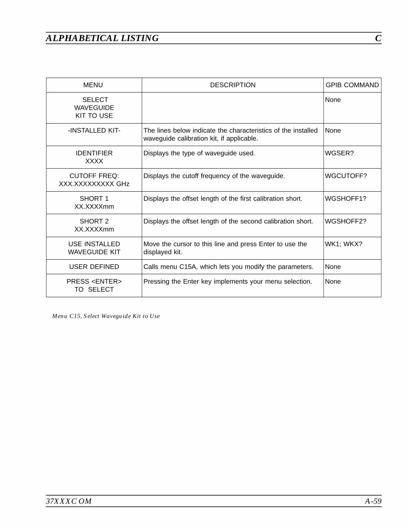
37XXXC OM A-59
ALPHABETICAL LISTING C
MENU DESCRIPTION GPIB COMMAND
SELECTWAVEGUIDEKIT TO USE
None
-INSTALLED KIT- The lines below indicate the characteristics of the installedwaveguide calibration kit, if applicable.
None
IDENTIFIERXXXX
Displays the type of waveguide used. WGSER?
CUTOFF FREQ:XXX.XXXXXXXXX GHz
Displays the cutoff frequency of the waveguide. WGCUTOFF?
SHORT 1XX.XXXXmm
Displays the offset length of the first calibration short. WGSHOFF1?
SHORT 2XX.XXXXmm
Displays the offset length of the second calibration short. WGSHOFF2?
USE INSTALLEDWAVEGUIDE KIT
Move the cursor to this line and press Enter to use thedisplayed kit.
WK1; WKX?
USER DEFINED Calls menu C15A, which lets you modify the parameters. None
PRESS <ENTER>TO SELECT
Pressing the Enter key implements your menu selection. None
Menu C15, Select Waveguide Kit to Use
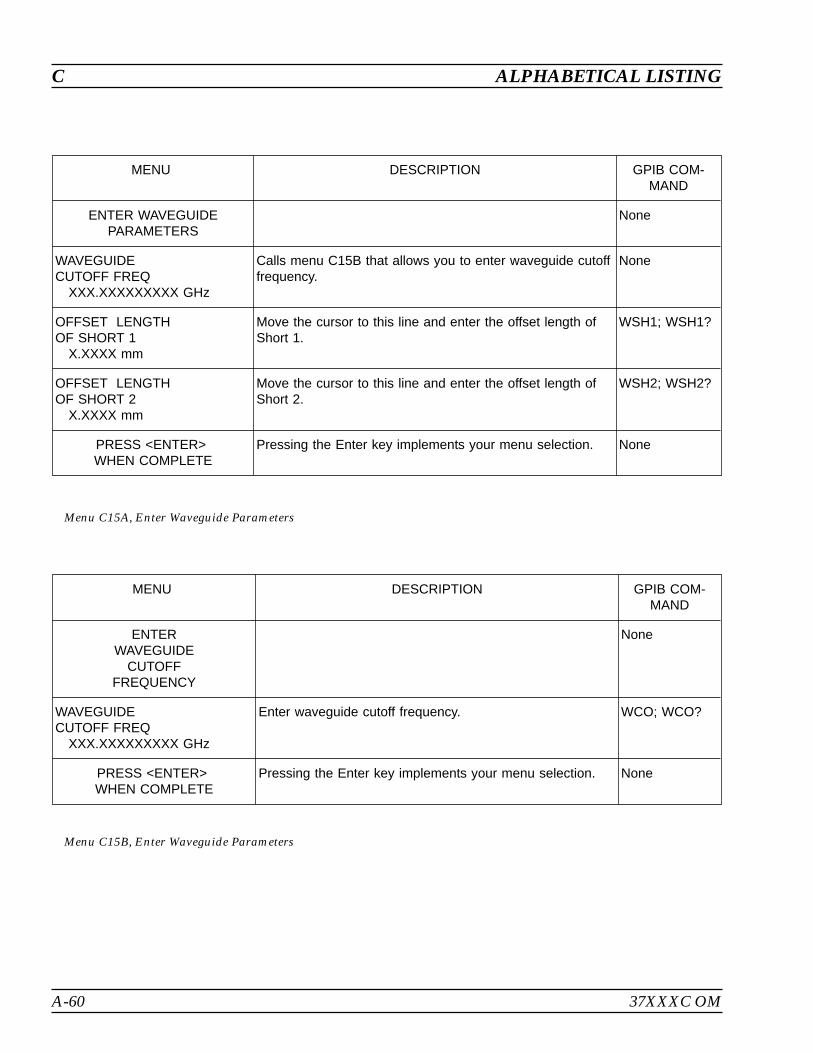
A-60 37XXXC OM
C ALPHABETICAL LISTING
MENU DESCRIPTION GPIB COM-MAND
ENTER WAVEGUIDEPARAMETERS
None
WAVEGUIDECUTOFF FREQ
XXX.XXXXXXXXX GHz
Calls menu C15B that allows you to enter waveguide cutofffrequency.
None
OFFSET LENGTHOF SHORT 1
X.XXXX mm
Move the cursor to this line and enter the offset length ofShort 1.
WSH1; WSH1?
OFFSET LENGTHOF SHORT 2
X.XXXX mm
Move the cursor to this line and enter the offset length ofShort 2.
WSH2; WSH2?
PRESS <ENTER>WHEN COMPLETE
Pressing the Enter key implements your menu selection. None
Menu C15A, Enter Waveguide Parameters
MENU DESCRIPTION GPIB COM-MAND
ENTERWAVEGUIDE
CUTOFFFREQUENCY
None
WAVEGUIDECUTOFF FREQ
XXX.XXXXXXXXX GHz
Enter waveguide cutoff frequency. WCO; WCO?
PRESS <ENTER>WHEN COMPLETE
Pressing the Enter key implements your menu selection. None
Menu C15B, Enter Waveguide Parameters
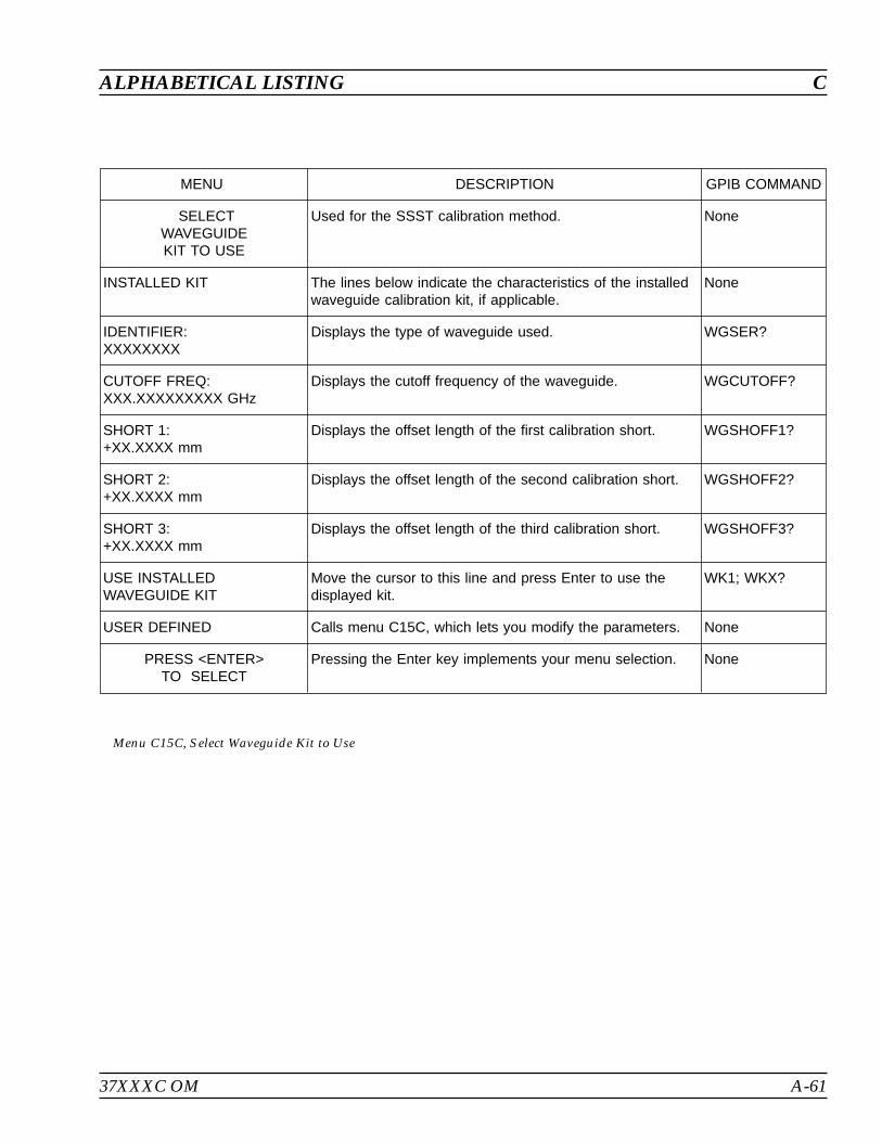
37XXXC OM A-61
ALPHABETICAL LISTING C
MENU DESCRIPTION GPIB COMMAND
SELECTWAVEGUIDEKIT TO USE
Used for the SSST calibration method. None
INSTALLED KIT The lines below indicate the characteristics of the installedwaveguide calibration kit, if applicable.
None
IDENTIFIER:XXXXXXXX
Displays the type of waveguide used. WGSER?
CUTOFF FREQ:XXX.XXXXXXXXX GHz
Displays the cutoff frequency of the waveguide. WGCUTOFF?
SHORT 1:+XX.XXXX mm
Displays the offset length of the first calibration short. WGSHOFF1?
SHORT 2:+XX.XXXX mm
Displays the offset length of the second calibration short. WGSHOFF2?
SHORT 3:+XX.XXXX mm
Displays the offset length of the third calibration short. WGSHOFF3?
USE INSTALLEDWAVEGUIDE KIT
Move the cursor to this line and press Enter to use thedisplayed kit.
WK1; WKX?
USER DEFINED Calls menu C15C, which lets you modify the parameters. None
PRESS <ENTER>TO SELECT
Pressing the Enter key implements your menu selection. None
Menu C15C, Select Waveguide Kit to Use

A-62 37XXXC OM
C ALPHABETICAL LISTING
MENU DESCRIPTION GPIB COM-MAND
ENTERWAVEGUIDE
PARAMETERS
Used for the SSST calibration method. None
WAVEGUIDECUTOFF FREQXXX.XXXXXXXXX GHz
Calls menu C15B that allows you to enter waveguide cutofffrequency.
None
OFFSET LENGTHOF SHORT 1+XXX.XXXX mm
Move the cursor to this line and enter the offset length ofShort 1.
WSH1; WSH1?
OFFSET LENGTHOF SHORT 2+XXX.XXXX mm
Move the cursor to this line and enter the offset length ofShort 2.
WSH2; WSH2?
OFFSET LENGTHOF SHORT 3+XXX.XXXX mm
Move the cursor to this line and enter the offset length ofShort 3.
WSH3; WSH3?
PRESS <ENTER>WHEN COMPLETE
Pressing the Enter key implements your menu selection. None
Menu C15D, Enter Waveguide Parameters
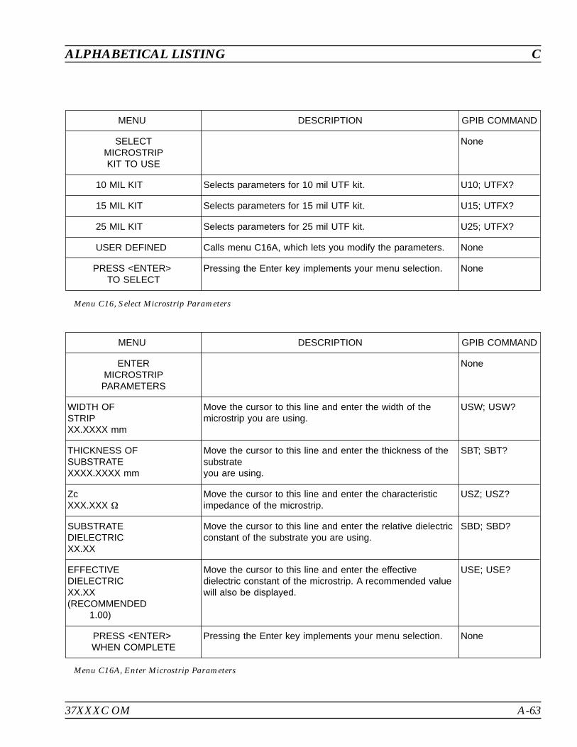
37XXXC OM A-63
ALPHABETICAL LISTING C
MENU DESCRIPTION GPIB COMMAND
ENTERMICROSTRIPPARAMETERS
None
WIDTH OFSTRIPXX.XXXX mm
Move the cursor to this line and enter the width of themicrostrip you are using.
USW; USW?
THICKNESS OFSUBSTRATEXXXX.XXXX mm
Move the cursor to this line and enter the thickness of thesubstrateyou are using.
SBT; SBT?
ZcXXX.XXX
Move the cursor to this line and enter the characteristicimpedance of the microstrip.
USZ; USZ?
SUBSTRATEDIELECTRICXX.XX
Move the cursor to this line and enter the relative dielectricconstant of the substrate you are using.
SBD; SBD?
EFFECTIVEDIELECTRICXX.XX(RECOMMENDED
1.00)
Move the cursor to this line and enter the effectivedielectric constant of the microstrip. A recommended valuewill also be displayed.
USE; USE?
PRESS <ENTER>WHEN COMPLETE
Pressing the Enter key implements your menu selection. None
Menu C16A, Enter Microstrip Parameters
MENU DESCRIPTION GPIB COMMAND
SELECTMICROSTRIPKIT TO USE
None
10 MIL KIT Selects parameters for 10 mil UTF kit. U10; UTFX?
15 MIL KIT Selects parameters for 15 mil UTF kit. U15; UTFX?
25 MIL KIT Selects parameters for 25 mil UTF kit. U25; UTFX?
USER DEFINED Calls menu C16A, which lets you modify the parameters. None
PRESS <ENTER>TO SELECT
Pressing the Enter key implements your menu selection. None
Menu C16, Select Microstrip Parameters
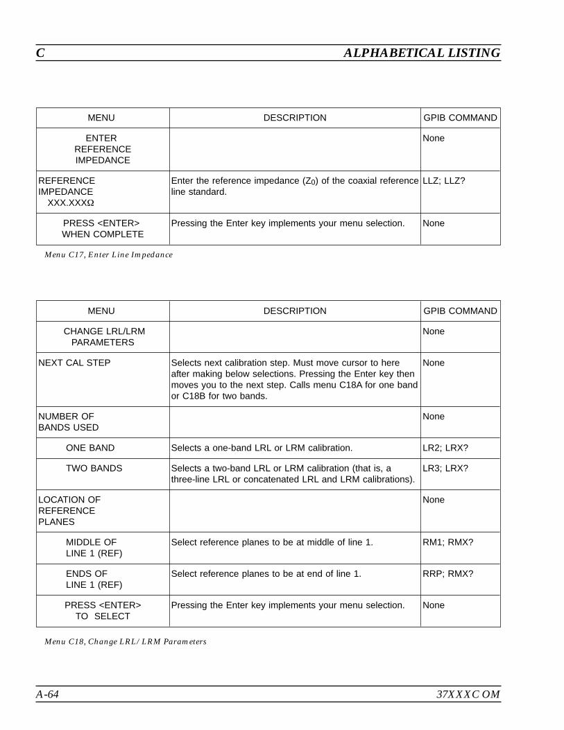
A-64 37XXXC OM
C ALPHABETICAL LISTING
MENU DESCRIPTION GPIB COMMAND
ENTERREFERENCEIMPEDANCE
None
REFERENCEIMPEDANCE
XXX.XXX
Enter the reference impedance (Z0) of the coaxial referenceline standard.
LLZ; LLZ?
PRESS <ENTER>WHEN COMPLETE
Pressing the Enter key implements your menu selection. None
Menu C17, Enter Line Impedance
MENU DESCRIPTION GPIB COMMAND
CHANGE LRL/LRMPARAMETERS
None
NEXT CAL STEP Selects next calibration step. Must move cursor to hereafter making below selections. Pressing the Enter key thenmoves you to the next step. Calls menu C18A for one bandor C18B for two bands.
None
NUMBER OFBANDS USED
None
ONE BAND Selects a one-band LRL or LRM calibration. LR2; LRX?
TWO BANDS Selects a two-band LRL or LRM calibration (that is, athree-line LRL or concatenated LRL and LRM calibrations).
LR3; LRX?
LOCATION OFREFERENCEPLANES
None
MIDDLE OFLINE 1 (REF)
Select reference planes to be at middle of line 1. RM1; RMX?
ENDS OFLINE 1 (REF)
Select reference planes to be at end of line 1. RRP; RMX?
PRESS <ENTER>TO SELECT
Pressing the Enter key implements your menu selection. None
Menu C18, Change LRL/LRM Parameters

37XXXC OM A-65
ALPHABETICAL LISTING C
MENU DESCRIPTION GPIB COM-MAND
CHANGE LRL/LRMPARAMETERS
None
NEXT CAL STEP Selects next calibration step. Must move cursor to hereafter making below selections. Pressing the Enter key thenmoves you to the next step. Calls menu C19.
None
CHARACTERIZECAL DEVICES
None
DEVICE 1LINE 1 (REF)X.XXXX mm
Enter length of line 1. LL1; LL1?
DEVICE 2LINE /MATCHX.XXXX mm/FULLBAND
Select device 2—LINE or MATCH; if line is selected, enterlength.
LL2; LM2;LX2?
PRESS <ENTER>TO SELECTOR SWITCH
Press Enter to select. If DEVICE 2 is chosen, pressing theEnter key toggles between LINE and MATCH.
None
Menu C18A, Change LRL/LRM Parameters
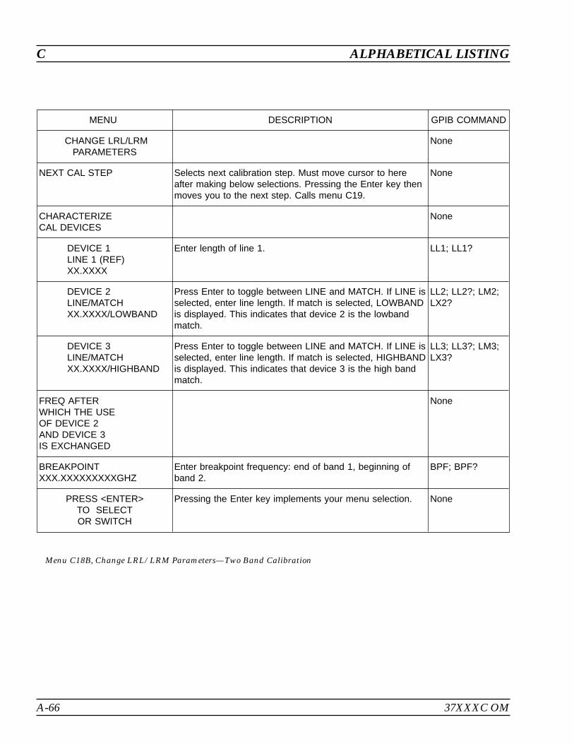
A-66 37XXXC OM
C ALPHABETICAL LISTING
MENU DESCRIPTION GPIB COMMAND
CHANGE LRL/LRMPARAMETERS
None
NEXT CAL STEP Selects next calibration step. Must move cursor to hereafter making below selections. Pressing the Enter key thenmoves you to the next step. Calls menu C19.
None
CHARACTERIZECAL DEVICES
None
DEVICE 1LINE 1 (REF)XX.XXXX
Enter length of line 1. LL1; LL1?
DEVICE 2LINE/MATCHXX.XXXX/LOWBAND
Press Enter to toggle between LINE and MATCH. If LINE isselected, enter line length. If match is selected, LOWBANDis displayed. This indicates that device 2 is the lowbandmatch.
LL2; LL2?; LM2;LX2?
DEVICE 3LINE/MATCHXX.XXXX/HIGHBAND
Press Enter to toggle between LINE and MATCH. If LINE isselected, enter line length. If match is selected, HIGHBANDis displayed. This indicates that device 3 is the high bandmatch.
LL3; LL3?; LM3;LX3?
FREQ AFTERWHICH THE USEOF DEVICE 2AND DEVICE 3IS EXCHANGED
None
BREAKPOINTXXX.XXXXXXXXXGHZ
Enter breakpoint frequency: end of band 1, beginning ofband 2.
BPF; BPF?
PRESS <ENTER>TO SELECTOR SWITCH
Pressing the Enter key implements your menu selection. None
Menu C18B, Change LRL/LRM Parameters—Two Band Calibration
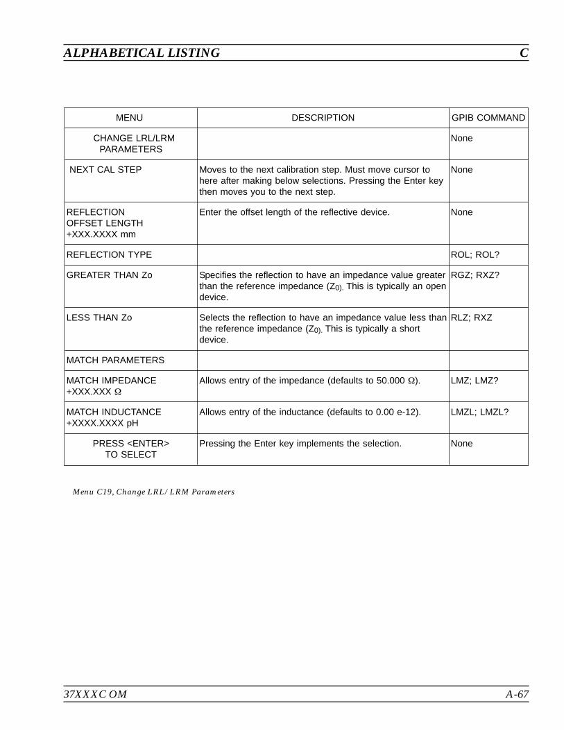
37XXXC OM A-67
ALPHABETICAL LISTING C
MENU DESCRIPTION GPIB COMMAND
CHANGE LRL/LRMPARAMETERS
None
NEXT CAL STEP Moves to the next calibration step. Must move cursor tohere after making below selections. Pressing the Enter keythen moves you to the next step.
None
REFLECTIONOFFSET LENGTH+XXX.XXXX mm
Enter the offset length of the reflective device. None
REFLECTION TYPE ROL; ROL?
GREATER THAN Zo Specifies the reflection to have an impedance value greaterthan the reference impedance (Z0). This is typically an opendevice.
RGZ; RXZ?
LESS THAN Zo Selects the reflection to have an impedance value less thanthe reference impedance (Z0). This is typically a shortdevice.
RLZ; RXZ
MATCH PARAMETERS
MATCH IMPEDANCE+XXX.XXX
Allows entry of the impedance (defaults to 50.000 ). LMZ; LMZ?
MATCH INDUCTANCE+XXXX.XXXX pH
Allows entry of the inductance (defaults to 0.00 e-12). LMZL; LMZL?
PRESS <ENTER>TO SELECT
Pressing the Enter key implements the selection. None
Menu C19, Change LRL/LRM Parameters
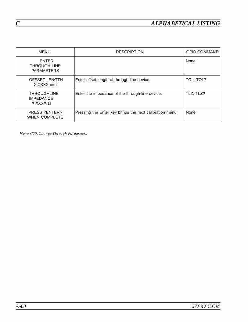
A-68 37XXXC OM
C ALPHABETICAL LISTING
MENU DESCRIPTION GPIB COMMAND
ENTERTHROUGH LINEPARAMETERS
None
OFFSET LENGTHX.XXXX mm
Enter offset length of through-line device. TOL; TOL?
THROUGHLINEIMPEDANCE
X.XXXX
Enter the impedance of the through-line device. TLZ; TLZ?
PRESS <ENTER>WHEN COMPLETE
Pressing the Enter key brings the next calibration menu. None
Menu C20, Change Through Parameters

37XXXC OM A-69
ALPHABETICAL LISTING C
MENU DESCRIPTION GPIB COMMAND
PORT XOFFSET SHORT 1
None
ENTER THEINDUCTANCECOEFFICIENTS
L0 [e-12 H]+XXXX.XXXX
Enter the inductance coeficients of the offset short. None
L1 [e-24 H/Hz]+XXXX.XXXX
Enter the inductance coeficients of the offset short. None
L2 [e-33 H/Hz2]+XXXX.XXXX
Enter the inductance coeficients of the offset short. None
L3 [e-42 H/Hz3]+XXXX.XXXX
Enter the inductance coeficients of the offset short. None
ENTER THEOFFSET LENGTH
OFFSET LENGTH+XXX.XXXX mm
Enter the offset length of the offset short. None
PRESS <ENTER>WHEN COMPLETE
Pressing the Enter key calls menu C21B. None
Menu C21A, Port X Offset Short 1

A-70 37XXXC OM
C ALPHABETICAL LISTING
MENU DESCRIPTION GPIB COMMAND
PORT XOFFSET SHORT 2
None
ENTER THEINDUCTANCECOEFFICIENTS
L0 [e-12 H]+XXXX.XXXX
Enter the inductance coeficients of the offset short. None
L1 [e-24 H/Hz]+XXXX.XXXX
Enter the inductance coeficients of the offset short. None
L2 [e-33 H/Hz2]+XXXX.XXXX
Enter the inductance coeficients of the offset short. None
L3 [e-42 H/Hz3]+XXXX.XXXX
Enter the inductance coeficients of the offset short. None
ENTER THEOFFSET LENGTH
OFFSET LENGTH+XXX.XXXX mm
Enter the offset length of the offset short. None
PRESS <ENTER>WHEN COMPLETE
Pressing the Enter key calls menu C3X, for a SSLTcalibration method, or menu C21B, for a SSST calibrationmethod.
None
Menu C21B, Port X Offset Short 2

37XXXC OM A-71
ALPHABETICAL LISTING C
MENU DESCRIPTION GPIB COMMAND
PORT XOFFSET SHORT 3
None
ENTER THEINDUCTANCECOEFFICIENTS
L0 [e-12 H]+XXXX.XXXX
Enter the inductance coeficients of the offset short. None
L1 [e-24 H/Hz]+XXXX.XXXX
Enter the inductance coeficients of the offset short. None
L2 [e-33 H/Hz2]+XXXX.XXXX
Enter the inductance coeficients of the offset short. None
L3 [e-42 H/Hz3]+XXXX.XXXX
Enter the inductance coeficients of the offset short. None
ENTER THEOFFSET LENGTH
OFFSET LENGTH+XXX.XXXX mm
Enter the offset length of the offset short. None
PRESS <ENTER>WHEN COMPLETE
Pressing the Enter key calls menu C3X. None
Menu C21C, Port X Offset Short 3

A-72 37XXXC OM
C ALPHABETICAL LISTING
MENU DESCRIPTION GPIB COMMAND
CALIBRATIONSEQUENCECOMPLETED
None
PRESS<SAVE/RECALL>TO STORE CALDATA ON DISK
OR
Pressing the SAVE/RECALL MENU Key displays menu SR,which lets you save your calibration data onto a disk orrecall previously saved calibration data from a disk. Whilethis menu provides a convenient point at which to save thecalibration data, it is not the only point allowed. You canuse the SAVE/RECALL MENU key at any point in themeasurement program.
None
PRESS <ENTER>TO PROCEED
Pressing the Enter key implements your menu selection. None
Menu Cal_Completed
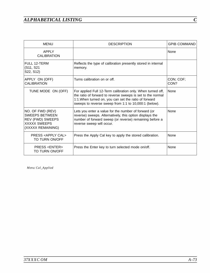
37XXXC OM A-73
ALPHABETICAL LISTING C
MENU DESCRIPTION GPIB COMMAND
APPLYCALIBRATION
None
FULL 12-TERM(S11, S21S22, S12)
Reflects the type of calibration presently stored in internalmemory.
APPLY ON (OFF)CALIBRATION
Turns calibration on or off. CON; COF;CON?
TUNE MODE ON (OFF) For applied Full 12-Term calibration only. When turned off,the ratio of forward to reverse sweeps is set to the normal1:1.When turned on, you can set the ratio of forwardsweeps to reverse sweep from 1:1 to 10,000:1 (below).
None
NO. OF FWD (REV)SWEEPS BETWEENREV (FWD) SWEEPSXXXXX SWEEPS(XXXXX REMAINING)
Lets you enter a value for the number of forward (orreverse) sweeps. Alternatively, this option displays thenumber of forward sweep (or reverse) remaining before areverse sweep will occur.
None
PRESS <APPLY CAL>TO TURN ON/OFF
Press the Apply Cal key to apply the stored calibration. None
PRESS <ENTER>TO TURN ON/OFF
Press the Enter key to turn selected mode on/off. None
Menu Cal_Applied
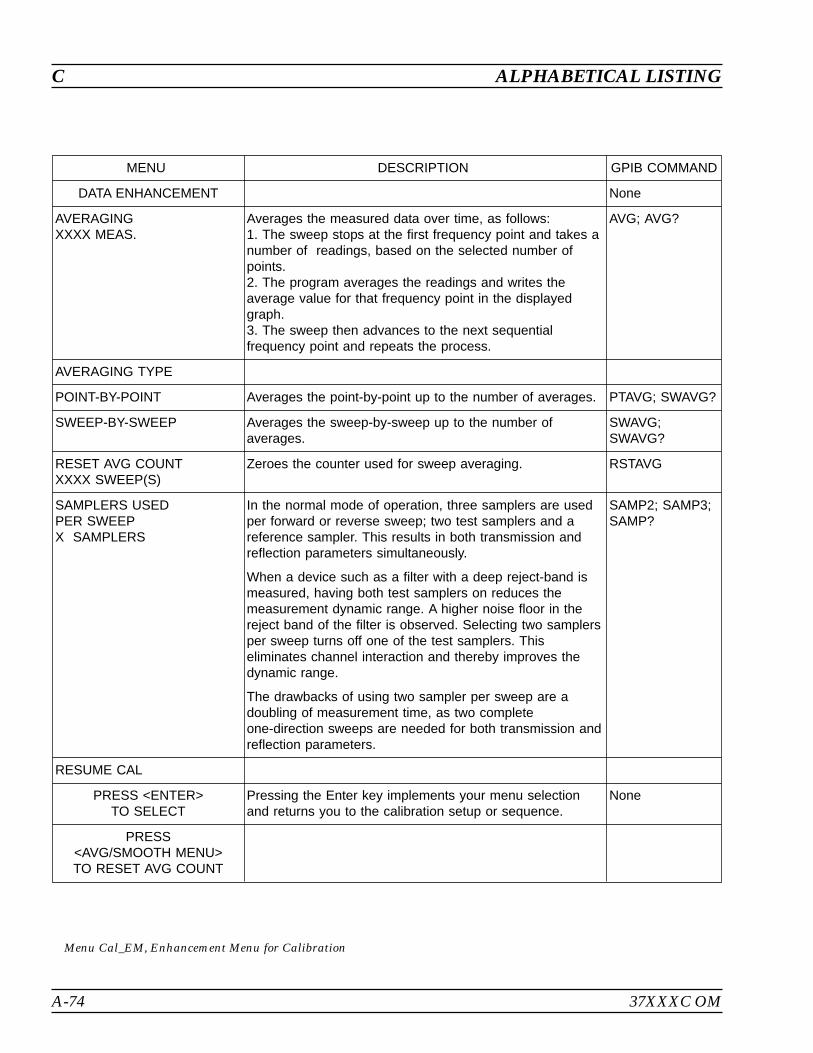
C ALPHABETICAL LISTING
A-74 37XXXC OM
MENU DESCRIPTION GPIB COMMAND
DATA ENHANCEMENT None
AVERAGINGXXXX MEAS.
Averages the measured data over time, as follows:1. The sweep stops at the first frequency point and takes anumber of readings, based on the selected number ofpoints.2. The program averages the readings and writes theaverage value for that frequency point in the displayedgraph.3. The sweep then advances to the next sequentialfrequency point and repeats the process.
AVG; AVG?
AVERAGING TYPE
POINT-BY-POINT Averages the point-by-point up to the number of averages. PTAVG; SWAVG?
SWEEP-BY-SWEEP Averages the sweep-by-sweep up to the number ofaverages.
SWAVG;SWAVG?
RESET AVG COUNTXXXX SWEEP(S)
Zeroes the counter used for sweep averaging. RSTAVG
SAMPLERS USEDPER SWEEPX SAMPLERS
In the normal mode of operation, three samplers are usedper forward or reverse sweep; two test samplers and areference sampler. This results in both transmission andreflection parameters simultaneously.
When a device such as a filter with a deep reject-band ismeasured, having both test samplers on reduces themeasurement dynamic range. A higher noise floor in thereject band of the filter is observed. Selecting two samplersper sweep turns off one of the test samplers. Thiseliminates channel interaction and thereby improves thedynamic range.
The drawbacks of using two sampler per sweep are adoubling of measurement time, as two completeone-direction sweeps are needed for both transmission andreflection parameters.
SAMP2; SAMP3;SAMP?
RESUME CAL
PRESS <ENTER>TO SELECT
Pressing the Enter key implements your menu selectionand returns you to the calibration setup or sequence.
None
PRESS<AVG/SMOOTH MENU>TO RESET AVG COUNT
Menu Cal_EM, Enhancement Menu for Calibration
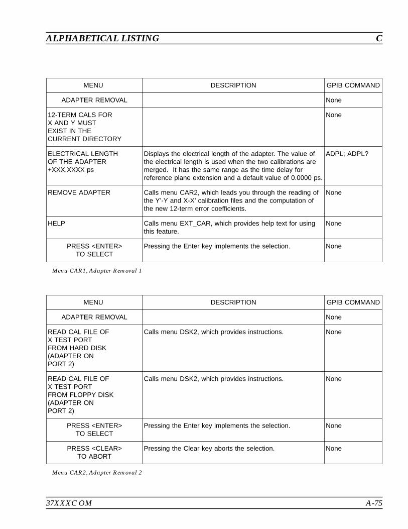
37XXXC OM A-75
ALPHABETICAL LISTING C
MENU DESCRIPTION GPIB COMMAND
ADAPTER REMOVAL None
12-TERM CALS FORX AND Y MUSTEXIST IN THECURRENT DIRECTORY
None
ELECTRICAL LENGTHOF THE ADAPTER+XXX.XXXX ps
Displays the electrical length of the adapter. The value ofthe electrical length is used when the two calibrations aremerged. It has the same range as the time delay forreference plane extension and a default value of 0.0000 ps.
ADPL; ADPL?
REMOVE ADAPTER Calls menu CAR2, which leads you through the reading ofthe Y’-Y and X-X’ calibration files and the computation ofthe new 12-term error coefficients.
None
HELP Calls menu EXT_CAR, which provides help text for usingthis feature.
None
PRESS <ENTER>TO SELECT
Pressing the Enter key implements the selection. None
Menu CAR1, Adapter Removal 1
MENU DESCRIPTION GPIB COMMAND
ADAPTER REMOVAL None
READ CAL FILE OFX TEST PORTFROM HARD DISK(ADAPTER ONPORT 2)
Calls menu DSK2, which provides instructions. None
READ CAL FILE OFX TEST PORTFROM FLOPPY DISK(ADAPTER ONPORT 2)
Calls menu DSK2, which provides instructions. None
PRESS <ENTER>TO SELECT
Pressing the Enter key implements the selection. None
PRESS <CLEAR>TO ABORT
Pressing the Clear key aborts the selection. None
Menu CAR2, Adapter Removal 2
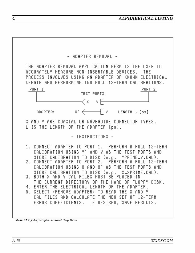
A-76 37XXXC OM
C ALPHABETICAL LISTING
Menu EXT_CAR, Adapter Removal Help Menu
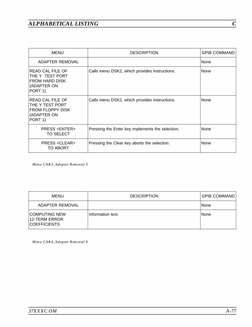
37XXXC OM A-77
ALPHABETICAL LISTING C
MENU DESCRIPTION GPIB COMMAND
ADAPTER REMOVAL None
READ CAL FILE OFTHE Y TEST PORTFROM HARD DISK(ADAPTER ONPORT 1)
Calls menu DSK2, which provides instructions. None
READ CAL FILE OFTHE Y TEST PORTFROM FLOPPY DISK(ADAPTER ONPORT 1)
Calls menu DSK2, which provides instructions. None
PRESS <ENTER>TO SELECT
Pressing the Enter key implements the selection. None
PRESS <CLEAR>TO ABORT
Pressing the Clear key aborts the selection. None
Menu CAR3, Adapter Removal 3
MENU DESCRIPTION GPIB COMMAND
ADAPTER REMOVAL None
COMPUTING NEW12-TERM ERRORCOEFFICIENTS
Information text. None
Menu CAR4, Adapter Removal 4

A-78 37XXXC OM
C ALPHABETICAL LISTING
MENU DESCRIPTION GPIB COMMAND
SELECTDISPLAY MODE
None
SINGLECHANNEL
Selects a single channel for display. You select the type ofdisplay in menu GT1 or GT2.
DSP; DSP?
DUALCHANNELS 1 & 3
Selects Channels 1 and 3 for display. You select the type ofdisplay in menu GT1 or GT2.
D13
OVERLAY DUALCHANNELS 1 & 3
Lets you simultaneously view the Channel 1 datasuperimposed over the Channel 3 data on a single display.Channel 1 trace displays in red and Channel 3 in yellow.
T13
DUALCHANNELS 2 & 4
Selects Channels 2 and 4 for display. You select the type ofdisplay in menu GT1 or GT2.
D24
OVERLAY DUALCHANNELS 2 & 4
Lets you simultaneously view the Channel 2 datasuperimposed over the Channel 4 data on a single display.Channel 2 trace displays in red and Channel 4 in yellow.
T24
ALL FOURCHANNELS
Selects all four channels for display. You select the type ofdisplay in menu GT1 or GT2.
D14
PRESS <ENTER>TO SELECT
Pressing the Enter key implements your menu selection.The menu remains on the screen until another menu isselected for display or until the CLEAR/RET LOC key ispressed.
None
Menu CM, Select Display Mode

37XXXC OM A-79
ALPHABETICAL LISTING D
MENU DESCRIPTION GPIB COMMAND
E/O MEASUREMENT None
MEASURE E/O DUT(MODULATOR)
This menu selection calls menu DE3, then DE3A. IODF or LDODF
DE-EMBED TRANSFERFUNCTION OF AGENERIC NETWORK
This menu selection calls menu DE4, then DE4A. IODF or LDODF
PRESS <ENTER>TO SELECT
Pressing the Enter key implements your menu selection. None
Menu DE1, E/O Measurement
Menu EXT_DE1, E/O Measurement
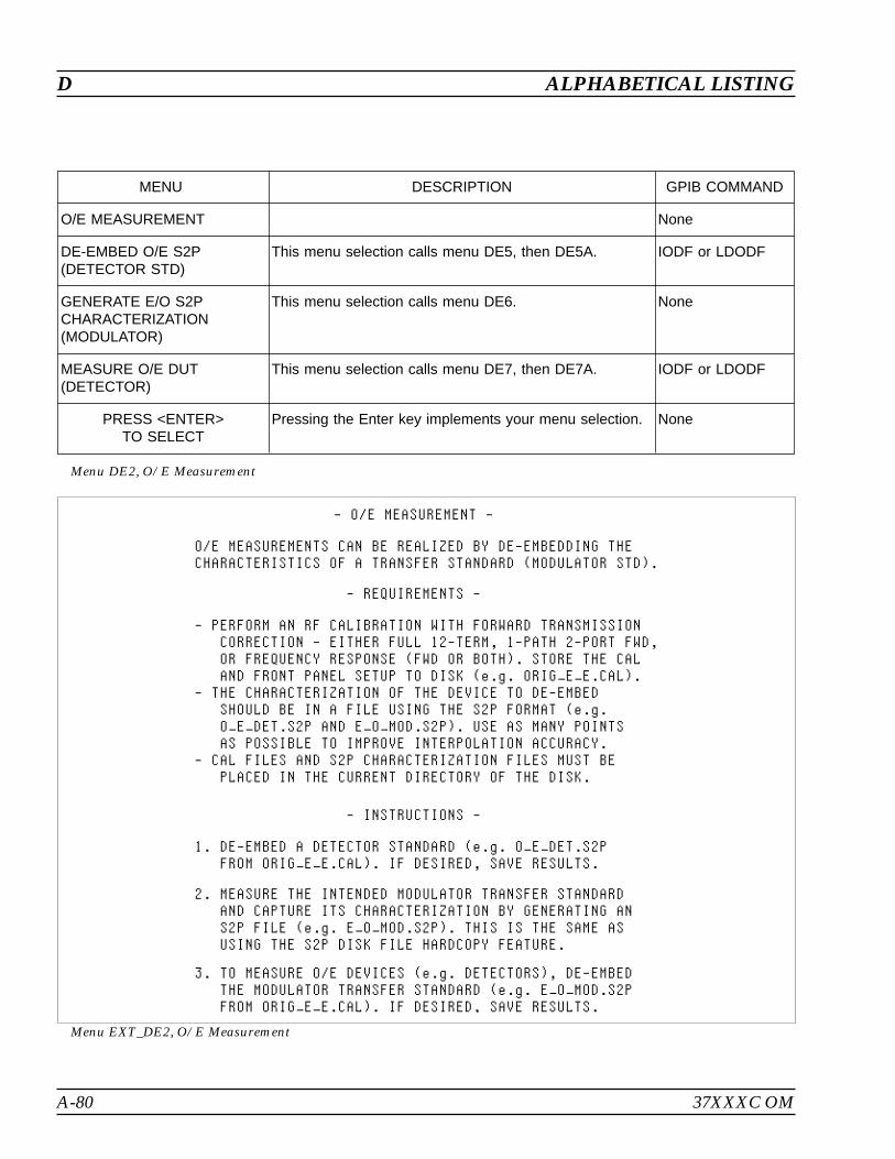
A-80 37XXXC OM
D ALPHABETICAL LISTING
MENU DESCRIPTION GPIB COMMAND
O/E MEASUREMENT None
DE-EMBED O/E S2P(DETECTOR STD)
This menu selection calls menu DE5, then DE5A. IODF or LDODF
GENERATE E/O S2PCHARACTERIZATION(MODULATOR)
This menu selection calls menu DE6. None
MEASURE O/E DUT(DETECTOR)
This menu selection calls menu DE7, then DE7A. IODF or LDODF
PRESS <ENTER>TO SELECT
Pressing the Enter key implements your menu selection. None
Menu DE2, O/E Measurement
Menu EXT_DE2, O/E Measurement

37XXXC OM A-81
ALPHABETICAL LISTING D
MENU DESCRIPTION GPIB COMMAND
E/O MEASUREMENT None
ORIGINAL CAL FILEWITH FWD TRANSCORRECTION
READ CAL FILEFROM HARD DISK
This menu selection calls menu DSK2 for *.CAL files onthe hard disk drive.
None
READ CAL FILEFROM FLOPPY DISK
This menu selection calls menu DSK2 for *.CAL files onthe floppy disk drive.
None
PRESS <ENTER>TO SELECT
Pressing the Enter key implements your menu selection. None
PRESS <CLEAR>TO ABORT
Pressing the Clear key aborts your this menu selectionand calls menu DE1.
None
Menu DE3, E/O Measurement
MENU DESCRIPTION GPIB COMMAND
E/O MEASUREMENT None
TRANSFER STANDARDTO BE DE-EMBEDED(DETECTOR STD)
READ S2P FILEFROM HARD DISK
This menu selection calls menu DSK2 for *.S2P files onthe hard disk drive.
None
READ S2P FILEFROM FLOPPY DISK
This menu selection calls menu DSK2 for *.S2P files onthe floppy disk drive.
None
PRESS <ENTER>TO SELECT
Pressing the Enter key implements your menu selection. None
PRESS <CLEAR>TO ABORT
Pressing the Clear key aborts this menu selection andcalls menu DE1.
None
Menu DE3A, E/O Measurement
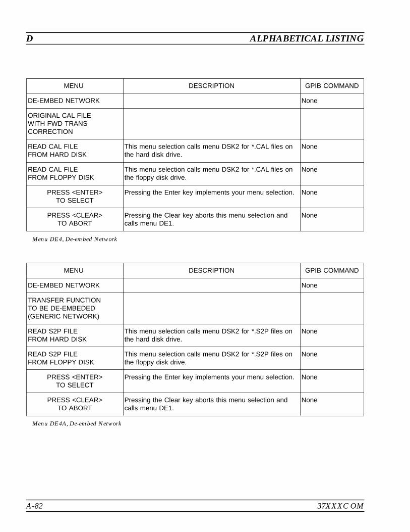
A-82 37XXXC OM
D ALPHABETICAL LISTING
MENU DESCRIPTION GPIB COMMAND
DE-EMBED NETWORK None
ORIGINAL CAL FILEWITH FWD TRANSCORRECTION
READ CAL FILEFROM HARD DISK
This menu selection calls menu DSK2 for *.CAL files onthe hard disk drive.
None
READ CAL FILEFROM FLOPPY DISK
This menu selection calls menu DSK2 for *.CAL files onthe floppy disk drive.
None
PRESS <ENTER>TO SELECT
Pressing the Enter key implements your menu selection. None
PRESS <CLEAR>TO ABORT
Pressing the Clear key aborts this menu selection andcalls menu DE1.
None
Menu DE4, De-embed Network
MENU DESCRIPTION GPIB COMMAND
DE-EMBED NETWORK None
TRANSFER FUNCTIONTO BE DE-EMBEDED(GENERIC NETWORK)
READ S2P FILEFROM HARD DISK
This menu selection calls menu DSK2 for *.S2P files onthe hard disk drive.
None
READ S2P FILEFROM FLOPPY DISK
This menu selection calls menu DSK2 for *.S2P files onthe floppy disk drive.
None
PRESS <ENTER>TO SELECT
Pressing the Enter key implements your menu selection. None
PRESS <CLEAR>TO ABORT
Pressing the Clear key aborts this menu selection andcalls menu DE1.
None
Menu DE4A, De-embed Network

37XXXC OM A-83
ALPHABETICAL LISTING D
MENU DESCRIPTION GPIB COMMAND
DE-EMBED O/E S2P None
ORIGINAL CAL FILEWITH FWD TRANSCORRECTION
READ CAL FILEFROM HARD DISK
This menu selection calls menu DSK2 for *.CAL files onthe hard disk drive.
None
READ CAL FILEFROM FLOPPY DISK
This menu selection calls menu DSK2 for *.CAL files onthe floppy disk drive.
None
PRESS <ENTER>TO SELECT
Pressing the Enter key implements your menu selection. None
PRESS <CLEAR>TO ABORT
Pressing the Clear key aborts this menu selection andcalls menu DE2.
None
Menu DE5, De-embed O/E S2P
MENU DESCRIPTION GPIB COMMAND
DE-EMBED O/E S2P None
TRANSFER STANDARDTO BE DE-EMBEDED(DETECTOR STANDARD)
READ S2P FILEFROM HARD DISK
This menu selection calls menu DSK2 for *.S2P files onthe hard disk drive.
None
READ S2P FILEFROM FLOPPY DISK
This menu selection calls menu DSK2 for *.S2P files onthe floppy disk drive.
None
PRESS <ENTER>TO SELECT
Pressing the Enter key implements your menu selection. None
PRESS <CLEAR>TO ABORT
Pressing the Clear key aborts this menu selection andcalls menu DE2.
None
Menu DE5A, De-embed O/E S2P
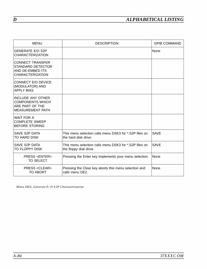
A-84 37XXXC OM
D ALPHABETICAL LISTING
MENU DESCRIPTION GPIB COMMAND
GENERATE E/O S2PCHARACTERIZATION
None
CONNECT TRANSFERSTANDARD DETECTORAND DE-EMBED ITSCHARACTERIZATION
CONNECT E/O DEVICE(MODULATOR) ANDAPPLY BIAS
INCLUDE ANY OTHERCOMPONENTS WHICHARE PART OF THEMEASUREMENT PATH
WAIT FOR ACOMPLETE SWEEPBEFORE STORING
SAVE S2P DATATO HARD DISK
This menu selection calls menu DSK3 for *.S2P files onthe hard disk drive.
SAVE
SAVE S2P DATATO FLOPPY DISK
This menu selection calls menu DSK3 for *.S2P files onthe floppy disk drive.
SAVE
PRESS <ENTER>TO SELECT
Pressing the Enter key implements your menu selection. None
PRESS <CLEAR>TO ABORT
Pressing the Clear key aborts this menu selection andcalls menu DE2.
None
Menu DE6, Generate E/O S2P Characterization
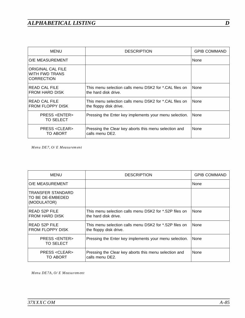
37XXXC OM A-85
ALPHABETICAL LISTING D
MENU DESCRIPTION GPIB COMMAND
O/E MEASUREMENT None
ORIGINAL CAL FILEWITH FWD TRANSCORRECTION
READ CAL FILEFROM HARD DISK
This menu selection calls menu DSK2 for *.CAL files onthe hard disk drive.
None
READ CAL FILEFROM FLOPPY DISK
This menu selection calls menu DSK2 for *.CAL files onthe floppy disk drive.
None
PRESS <ENTER>TO SELECT
Pressing the Enter key implements your menu selection. None
PRESS <CLEAR>TO ABORT
Pressing the Clear key aborts this menu selection andcalls menu DE2.
None
Menu DE7, O/E Measurement
MENU DESCRIPTION GPIB COMMAND
O/E MEASUREMENT None
TRANSFER STANDARDTO BE DE-EMBEDED(MODULATOR)
READ S2P FILEFROM HARD DISK
This menu selection calls menu DSK2 for *.S2P files onthe hard disk drive.
None
READ S2P FILEFROM FLOPPY DISK
This menu selection calls menu DSK2 for *.S2P files onthe floppy disk drive.
None
PRESS <ENTER>TO SELECT
Pressing the Enter key implements your menu selection. None
PRESS <CLEAR>TO ABORT
Pressing the Clear key aborts this menu selection andcalls menu DE2.
None
Menu DE7A, O/E Measurement
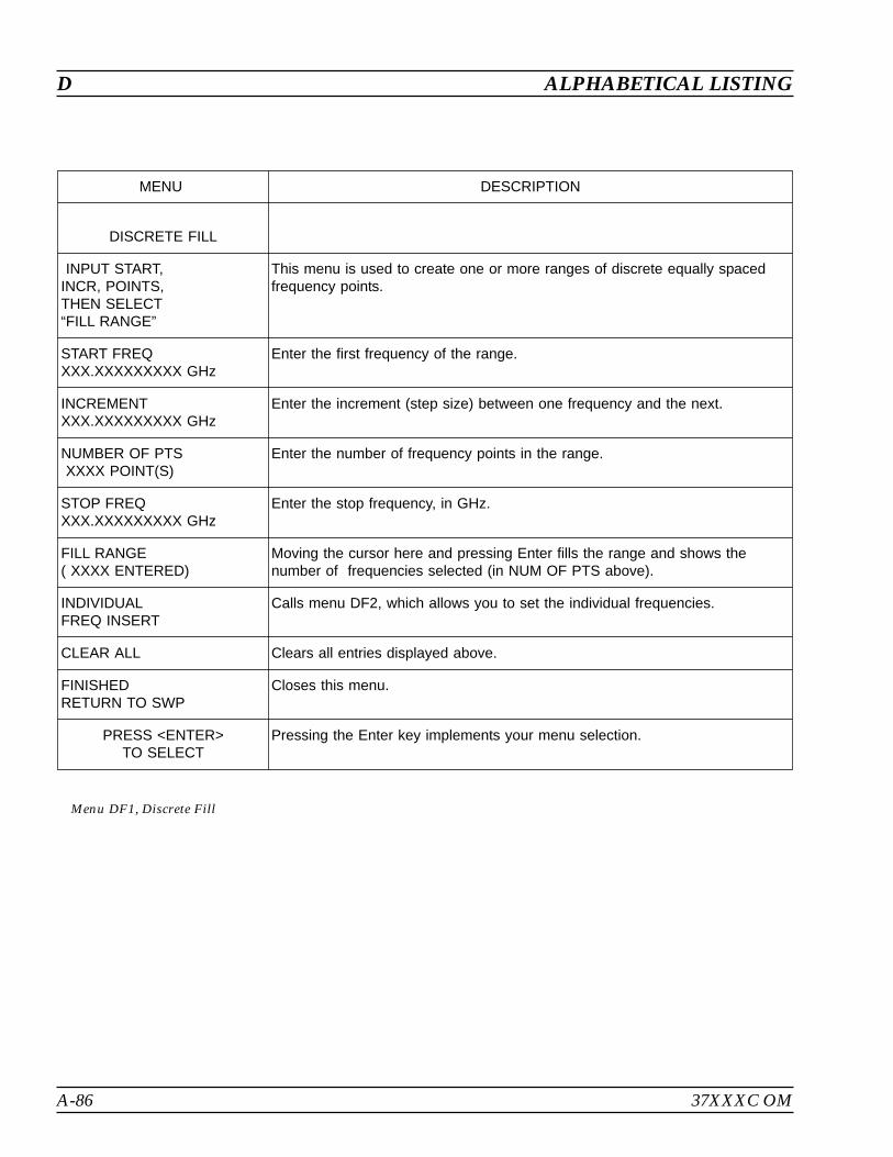
A-86 37XXXC OM
D ALPHABETICAL LISTING
MENU DESCRIPTION
DISCRETE FILL
INPUT START,INCR, POINTS,THEN SELECT“FILL RANGE”
This menu is used to create one or more ranges of discrete equally spacedfrequency points.
START FREQXXX.XXXXXXXXX GHz
Enter the first frequency of the range.
INCREMENTXXX.XXXXXXXXX GHz
Enter the increment (step size) between one frequency and the next.
NUMBER OF PTSXXXX POINT(S)
Enter the number of frequency points in the range.
STOP FREQXXX.XXXXXXXXX GHz
Enter the stop frequency, in GHz.
FILL RANGE( XXXX ENTERED)
Moving the cursor here and pressing Enter fills the range and shows thenumber of frequencies selected (in NUM OF PTS above).
INDIVIDUALFREQ INSERT
Calls menu DF2, which allows you to set the individual frequencies.
CLEAR ALL Clears all entries displayed above.
FINISHEDRETURN TO SWP
Closes this menu.
PRESS <ENTER>TO SELECT
Pressing the Enter key implements your menu selection.
Menu DF1, Discrete Fill
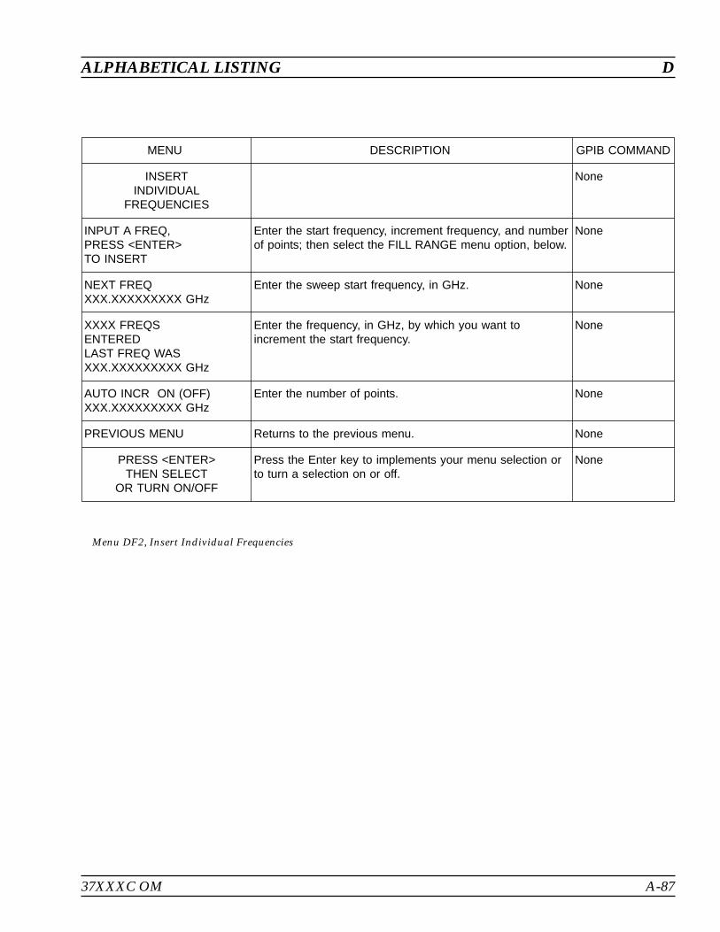
37XXXC OM A-87
ALPHABETICAL LISTING D
MENU DESCRIPTION GPIB COMMAND
INSERTINDIVIDUAL
FREQUENCIES
None
INPUT A FREQ,PRESS <ENTER>TO INSERT
Enter the start frequency, increment frequency, and numberof points; then select the FILL RANGE menu option, below.
None
NEXT FREQXXX.XXXXXXXXX GHz
Enter the sweep start frequency, in GHz. None
XXXX FREQSENTEREDLAST FREQ WASXXX.XXXXXXXXX GHz
Enter the frequency, in GHz, by which you want toincrement the start frequency.
None
AUTO INCR ON (OFF)XXX.XXXXXXXXX GHz
Enter the number of points. None
PREVIOUS MENU Returns to the previous menu. None
PRESS <ENTER>THEN SELECT
OR TURN ON/OFF
Press the Enter key to implements your menu selection orto turn a selection on or off.
None
Menu DF2, Insert Individual Frequencies
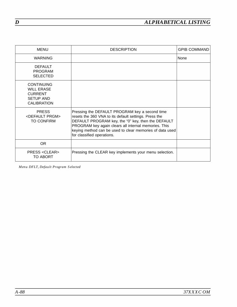
A-88 37XXXC OM
D ALPHABETICAL LISTING
MENU DESCRIPTION GPIB COMMAND
WARNING None
DEFAULTPROGRAMSELECTED
CONTINUINGWILL ERASECURRENTSETUP ANDCALIBRATION
PRESS<DEFAULT PRGM>
TO CONFIRM
Pressing the DEFAULT PROGRAM key a second timeresets the 360 VNA to its default settings. Press theDEFAULT PROGRAM key, the “0” key, then the DEFAULTPROGRAM key again clears all internal memories. Thiskeying method can be used to clear memories of data usedfor classified operations.
OR
PRESS <CLEAR>TO ABORT
Pressing the CLEAR key implements your menu selection.
Menu DFLT, Default Program Selected
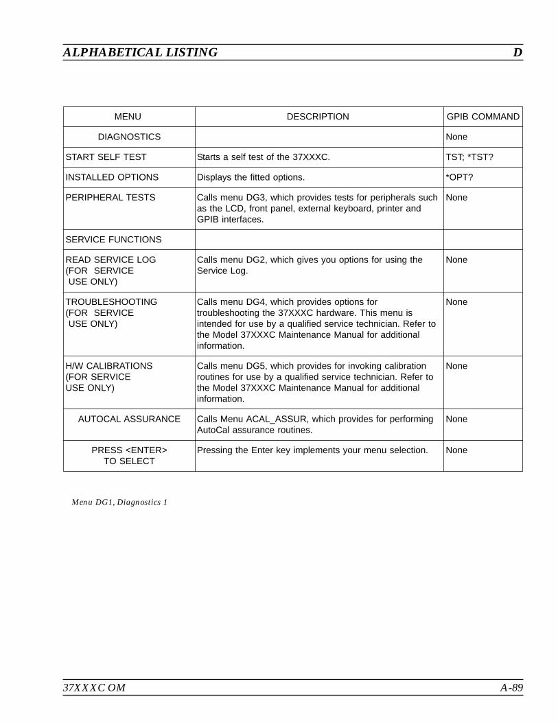
37XXXC OM A-89
ALPHABETICAL LISTING D
MENU DESCRIPTION GPIB COMMAND
DIAGNOSTICS None
START SELF TEST Starts a self test of the 37XXXC. TST; *TST?
INSTALLED OPTIONS Displays the fitted options. *OPT?
PERIPHERAL TESTS Calls menu DG3, which provides tests for peripherals suchas the LCD, front panel, external keyboard, printer andGPIB interfaces.
None
SERVICE FUNCTIONS
READ SERVICE LOG(FOR SERVICEUSE ONLY)
Calls menu DG2, which gives you options for using theService Log.
None
TROUBLESHOOTING(FOR SERVICEUSE ONLY)
Calls menu DG4, which provides options fortroubleshooting the 37XXXC hardware. This menu isintended for use by a qualified service technician. Refer tothe Model 37XXXC Maintenance Manual for additionalinformation.
None
H/W CALIBRATIONS(FOR SERVICEUSE ONLY)
Calls menu DG5, which provides for invoking calibrationroutines for use by a qualified service technician. Refer tothe Model 37XXXC Maintenance Manual for additionalinformation.
None
AUTOCAL ASSURANCE Calls Menu ACAL_ASSUR, which provides for performingAutoCal assurance routines.
None
PRESS <ENTER>TO SELECT
Pressing the Enter key implements your menu selection. None
Menu DG1, Diagnostics 1
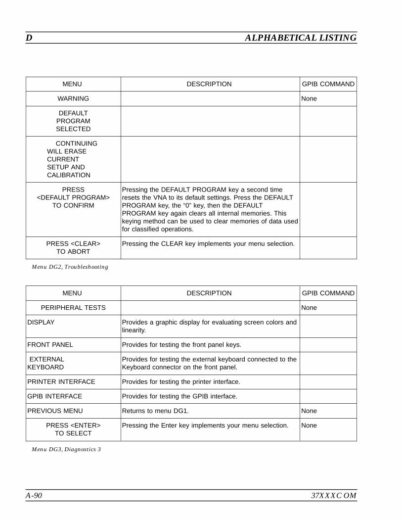
A-90 37XXXC OM
D ALPHABETICAL LISTING
MENU DESCRIPTION GPIB COMMAND
PERIPHERAL TESTS None
DISPLAY Provides a graphic display for evaluating screen colors andlinearity.
FRONT PANEL Provides for testing the front panel keys.
EXTERNALKEYBOARD
Provides for testing the external keyboard connected to theKeyboard connector on the front panel.
PRINTER INTERFACE Provides for testing the printer interface.
GPIB INTERFACE Provides for testing the GPIB interface.
PREVIOUS MENU Returns to menu DG1. None
PRESS <ENTER>TO SELECT
Pressing the Enter key implements your menu selection. None
Menu DG3, Diagnostics 3
MENU DESCRIPTION GPIB COMMAND
WARNING None
DEFAULTPROGRAMSELECTED
CONTINUINGWILL ERASECURRENTSETUP ANDCALIBRATION
PRESS<DEFAULT PROGRAM>
TO CONFIRM
Pressing the DEFAULT PROGRAM key a second timeresets the VNA to its default settings. Press the DEFAULTPROGRAM key, the “0” key, then the DEFAULTPROGRAM key again clears all internal memories. Thiskeying method can be used to clear memories of data usedfor classified operations.
PRESS <CLEAR>TO ABORT
Pressing the CLEAR key implements your menu selection.
Menu DG2, Troubleshooting

37XXXC OM A-91
ALPHABETICAL LISTING D
MENU DESCRIPTION GPIB COM-MAND
FLOPPY DISKUTILITIES
None
DISPLAYDIRECTORY
Directory displays in the screen’s data area. Press <1> forprevious page, <2> for next page, <0> for first page, and<3> for last page.
DIR
DELETE FILES Calls DSK6, which lets you delete data files. None
COPY FILESTO HARD DISK
Calls DSK8, which lets you copy files to the hard disk. None
FORMATFLOPPY DISK
Formats the floppy disk. INT
COMMAND LINE Prompts a one-line dialog box that allows you to enter acommand. The dialog box remains open only for the userinterface.
None
HARD DISKUTILITIES
Calls DSK1-HD, which provides hard disk utilities. None
PRESS <ENTER>TO SELECT
Pressing Enter implements your menu selection. You will bereturned to the previous menu when your selection is made.
None
Menu DSK_FD, Floppy Disk Utilities
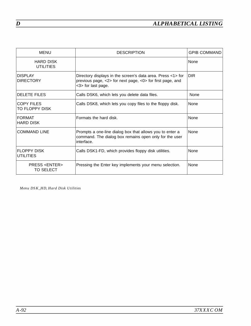
A-92 37XXXC OM
D ALPHABETICAL LISTING
MENU DESCRIPTION GPIB COMMAND
HARD DISKUTILITIES
None
DISPLAYDIRECTORY
Directory displays in the screen’s data area. Press <1> forprevious page, <2> for next page, <0> for first page, and<3> for last page.
DIR
DELETE FILES Calls DSK6, which lets you delete data files. None
COPY FILESTO FLOPPY DISK
Calls DSK8, which lets you copy files to the floppy disk. None
FORMATHARD DISK
Formats the hard disk. None
COMMAND LINE Prompts a one-line dialog box that allows you to enter acommand. The dialog box remains open only for the userinterface.
None
FLOPPY DISKUTILITIES
Calls DSK1-FD, which provides floppy disk utilities. None
PRESS <ENTER>TO SELECT
Pressing the Enter key implements your menu selection. None
Menu DSK_HD, Hard Disk Utilities

37XXXC OM A-93
ALPHABETICAL LISTING D
MENU DESCRIPTION GPIB COMMAND
SELECT FILETO READ
None
FILE 1 Displays the data stored in file number 1.
FILE 2 Displays the data stored in file number 2.
FILE 3 Displays the data stored in file number 3.
FILE 4 Displays the data stored in file number 4.
FILE 5 Displays the data stored in file number 5.
FILE 6 Displays the data stored in file number 6.
FILE 7 Displays the data stored in file number 7.
FILE 8 Displays the data stored in file number 8.
PREVIOUS MENU Returns to the previous menu. None
PRESS <ENTER>TO SELECT
Pressing the Enter key implements your menu selection. None
PRESS <1> FORPREVIOUS PAGE
Pressing the “1" key on the keypad returns to the previouspage.
PRESS <2>FOR NEXT PAGE
Pressing the “2" key on the keypad produces the nextpage.
None
Menu DSK2, Select File to Read

A-94 37XXXC OM
D ALPHABETICAL LISTING
MENU DESCRIPTION GPIB COMMAND
SELECT FILETO OVERWRITE
None
CREATE NEW FILE
FILE 1 Select file number 1 to be overwritten with new data.
FILE 2 Select file number 2 to be overwritten with new data.
FILE 3 Select file number 3 to be overwritten with new data.
FILE 4 Select file number 4 to be overwritten with new data.
FILE 5 Select file number 5 to be overwritten with new data.
FILE 6 Select file number 6 to be overwritten with new data.
FILE 7 Select file number 7 to be overwritten with new data.
FILE 8 Select file number 8 to be overwritten with new data.
PREVIOUS MENU Returns to the previous menu. None
PRESS <ENTER>TO SELECT
Pressing the Enter key implements your menu selection. None
PRESS <1> FORPREVIOUS PAGE
Pressing the “1" key on the keypad returns to the previouspage.
PRESS <2>FOR NEXT PAGE
Pressing the “2" key on the keypad produces the nextpage.
None
Menu DSK3, Select File to Overwrite
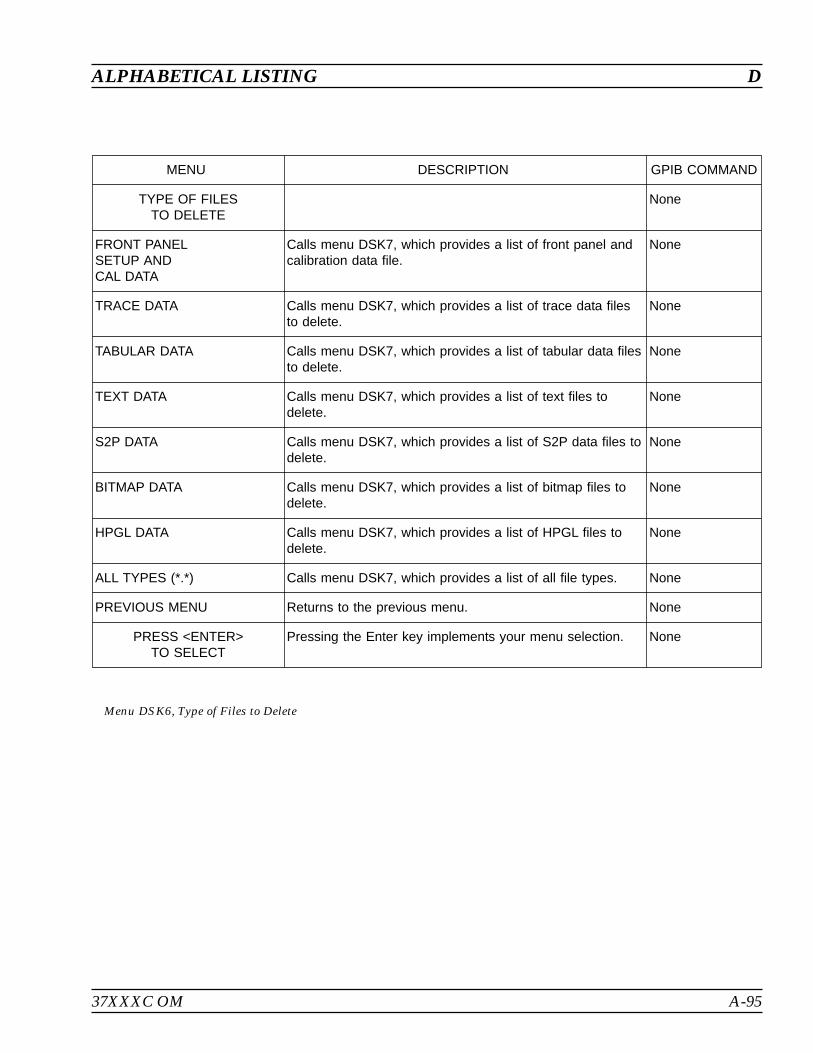
37XXXC OM A-95
ALPHABETICAL LISTING D
MENU DESCRIPTION GPIB COMMAND
TYPE OF FILESTO DELETE
None
FRONT PANELSETUP ANDCAL DATA
Calls menu DSK7, which provides a list of front panel andcalibration data file.
None
TRACE DATA Calls menu DSK7, which provides a list of trace data filesto delete.
None
TABULAR DATA Calls menu DSK7, which provides a list of tabular data filesto delete.
None
TEXT DATA Calls menu DSK7, which provides a list of text files todelete.
None
S2P DATA Calls menu DSK7, which provides a list of S2P data files todelete.
None
BITMAP DATA Calls menu DSK7, which provides a list of bitmap files todelete.
None
HPGL DATA Calls menu DSK7, which provides a list of HPGL files todelete.
None
ALL TYPES (*.*) Calls menu DSK7, which provides a list of all file types. None
PREVIOUS MENU Returns to the previous menu. None
PRESS <ENTER>TO SELECT
Pressing the Enter key implements your menu selection. None
Menu DSK6, Type of Files to Delete

A-96 37XXXC OM
D ALPHABETICAL LISTING
MENU DESCRIPTION GPIB COMMAND
SELECT FILETO DELETE
None
FILE 1 Selects file number 1 data to be deleted.
FILE 2 Selects file number 2 data to be deleted.
FILE 3 Selects file number 3 data to be deleted.
FILE 4 Selects file number 4 data to be deleted.
FILE 5 Selects file number 5 data to be deleted.
FILE 6 Selects file number 6 data to be deleted.
FILE 7 Selects file number 7 data to be deleted.
FILE 8 Selects file number 8 data to be deleted.
PREVIOUS MENU Returns to the previous menu. None
PRESS <ENTER>TO SELECT
Pressing the Enter key implements your menu selection. None
PRESS <1> FORPREVIOUS PAGE
Pressing the “1" key on the keypad returns to the previouspage.
PRESS <2>FOR NEXT PAGE
Pressing the “2" key on the keypad produces the nextpage.
None
Menu DSK7, Select File to Delete

37XXXC OM A-97
ALPHABETICAL LISTING D
MENU DESCRIPTION GPIB COMMAND
TYPE OF FILESTO COPY
None
FRONT PANELSETUP ANDCAL DATA
Calls menu DSK9, which provides a list of front panel andcalibration data file.
None
TRACE DATA Calls menu DSK9, which provides a list of trace data filesto copy.
None
TABULAR DATA Calls menu DSK9, which provides a list of tabular data filesto copy.
None
TEXT DATA Calls menu DSK9, which provides a list of text files to copy. None
S2P DATA Calls menu DSK9, which provides a list of S2P files tocopy.
None
BITMAP DATA Calls menu DSK9, which provides a list of bitmap files tocopy.
None
HPGL DATA Calls menu DSK9, which provides a list of HPGL files tocopy.
None
ALL TYPES (*.*) Calls menu DSK9, which provides a list of all file types. None
PREVIOUS MENU Returns to the previous menu. None
PRESS <ENTER>TO SELECT
Pressing the Enter key implements your menu selection. None
Menu DSK8, Type of Files to Copy

A-98 37XXXC OM
D ALPHABETICAL LISTING
MENU DESCRIPTION GPIB COMMAND
SELECT FILETO COPY
None
FILE 1 Selects file number 1 data to be copied. COPY
FILE 2 Selects file number 2 data to be copied. COPY
FILE 3 Selects file number 3 data to be copied. COPY
FILE 4 Selects file number 4 data to be copied. COPY
FILE 5 Selects file number 5 data to be copied. COPY
FILE 6 Selects file number 6 data to be copied. COPY
FILE 7 Selects file number 7 data to be copied. COPY
FILE 8 Selects file number 8 data to be copied. COPY
PREVIOUS MENU Returns to the previous menu. None
PRESS <ENTER>TO SELECT
Pressing the Enter key implements your menu selection. None
PRESS <1> FORPREVIOUS PAGE
Pressing the “1" key on the keypad returns to the previouspage.
PRESS <2>FOR NEXT PAGE
Pressing the “2" key on the keypad produces the nextpage.
None
Menu DSK9, Select File to Copy
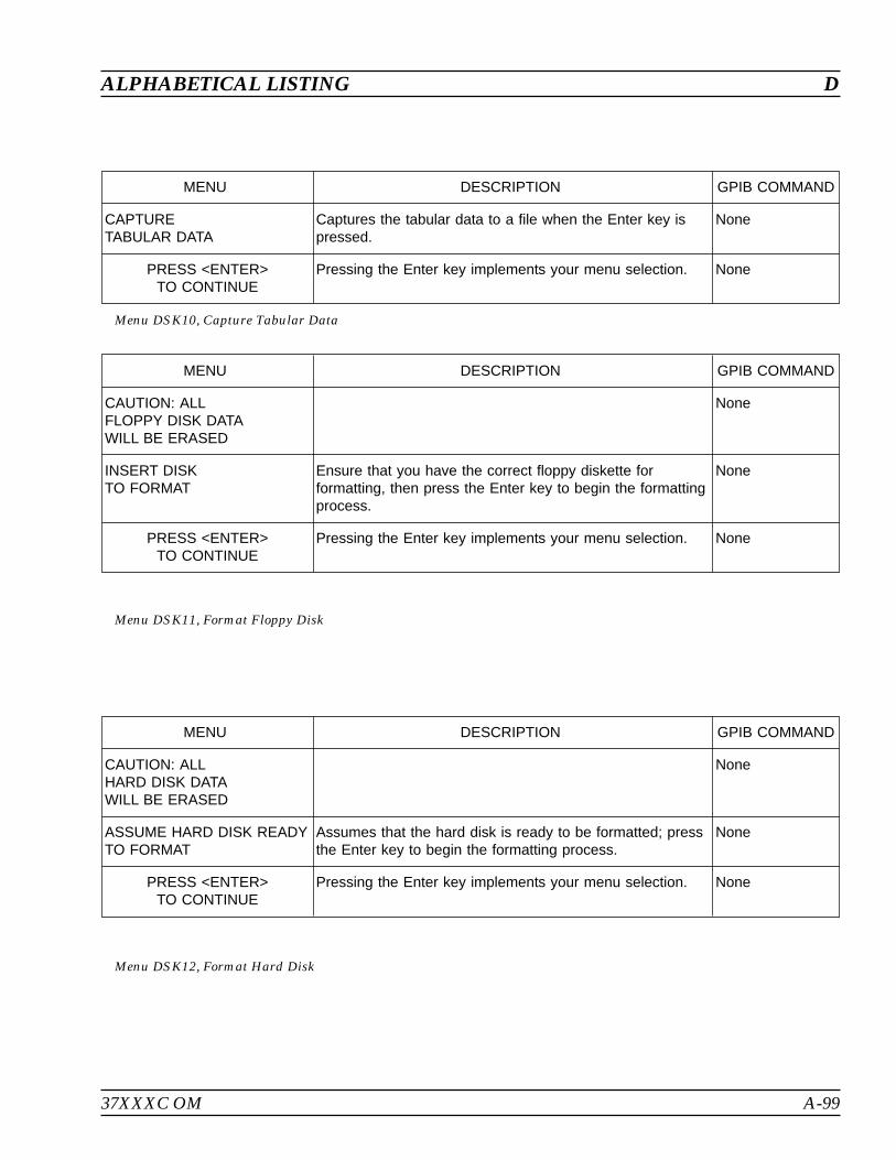
37XXXC OM A-99
ALPHABETICAL LISTING D
MENU DESCRIPTION GPIB COMMAND
CAPTURETABULAR DATA
Captures the tabular data to a file when the Enter key ispressed.
None
PRESS <ENTER>TO CONTINUE
Pressing the Enter key implements your menu selection. None
Menu DSK10, Capture Tabular Data
MENU DESCRIPTION GPIB COMMAND
CAUTION: ALLFLOPPY DISK DATAWILL BE ERASED
None
INSERT DISKTO FORMAT
Ensure that you have the correct floppy diskette forformatting, then press the Enter key to begin the formattingprocess.
None
PRESS <ENTER>TO CONTINUE
Pressing the Enter key implements your menu selection. None
Menu DSK11, Format Floppy Disk
MENU DESCRIPTION GPIB COMMAND
CAUTION: ALLHARD DISK DATAWILL BE ERASED
None
ASSUME HARD DISK READYTO FORMAT
Assumes that the hard disk is ready to be formatted; pressthe Enter key to begin the formatting process.
None
PRESS <ENTER>TO CONTINUE
Pressing the Enter key implements your menu selection. None
Menu DSK12, Format Hard Disk

A-100 37XXXC OM
E ALPHABETICAL LISTING
MENU DESCRIPTION GPIB COMMAND
DATA ENHANCEMENT None
AVERAGINGXXXX MEAS.
Averages the measured data over time, as follows:1. The sweep stops at the first frequency point and takes anumber of readings, based on the selected number ofpoints.2. The program averages the readings and writes theaverage value for that frequency point in the displayedgraph.3. The sweep then advances to the next sequentialfrequency point and repeats the process.
AVG; AVG?
AVERAGING TYPE
POINT-BY-POINT Averages the point-by-point up to the number of averages. PTAVG; SWAVG?
SWEEP-BY-SWEEP Averages the sweep-by-sweep up to the number ofsweeps.
SWAVG;SWAVG?
RESET AVG COUNTXXXX SWEEP(S)
Zeros the counter used for sweep averaging RSTAVG
SMOOTHINGXX.XX PERCENTOF SWEEPXXX POINT(S)
Smooths the measured data over frequency, as follows:1. The program divides the overall sweep into smallersegments, based on the selected percent-of-span. (Refer toSection 4-4 and Figure 4-23 for a description and exampleof smoothing.)2. It takes a data reading at each frequency point withinthat percent-of-span segment.3. It averages the readings with a raised Hamming windowand writes that magnitude value at the mid-frequency pointof the segment in the displayed graph or Smith chart.4. It then advances the percent-of-span segment toencompass the next sequential group of frequency pointsand repeats the process.The displayed number of points represents the number ofpoints for a given percent of sweep and is based on themax data points, and the sweep start and stop.
SON; SON?;SOF; SOF?
SAMPLERS USEDPER SWEEPX SAMPLERS
Sets the number of samplers used per sweep. SAMP2; SAMP3;SAMP?
PRESS <ENTER>TO SELECT
Pressing the Enter key implements your menu selection. None
PRESS<AVG/SMOOTH MENU>TO RESET AVG COUNT
Menu EM, Enhancement Menu

37XXXC OM A-101
ALPHABETICAL LISTING G
MENU DESCRIPTION GPIB COMMAND
SWEPT FREQUENCYGAIN COMPRESSION
None
NOMINAL OFFSET-XX.XX dB
Shows gain of nominal offset. This value is the approximategain (or loss) of the external devices preceding the AUT(amplifier under test). Specifically, the gain of the amplifierand attenuator combination. This value is used wheneverflat test port power is turned OFF (while still existing) toprevent an unexpected jump in the power to the AUT.
NOFST?
CALIBRATEFOR FLATNESS(NO CAL EXISTS)
Calls menu GC_SU8, which provides calibration options. None
FLATNESSCORRECTIONAT -XX.XX dBm
Shows value of the flatness correction. FPX?
CALIBRATERECEIVER(NO CAL EXISTS)
Calls menu GC_RCVR, which provides calibration options. None
NORMALIZE S21(NOT STORED)
Calls menu GC_NORM. None
GAIN COMPRESSIONPOINT (0 dB REF)XX.XX dB
This option is used with marker search functions. Valuehas a range from 0.05 to 9.99 dB and a default value of1.00 dB. The search value is [negative] the gaincompression point value. The reference is based on(maximum) with tracking ON.
GCMP; GCMP?
TEST AUT Closes the extended menu and displays the dual channels1 & 3, with channel 3 active.
None
EXIT APPLICATION Exits the gain compression application and returns toS-parameter measurements. It restores the measurementsetup.
None
Menu GC1, Swept Frequency Gain Compression
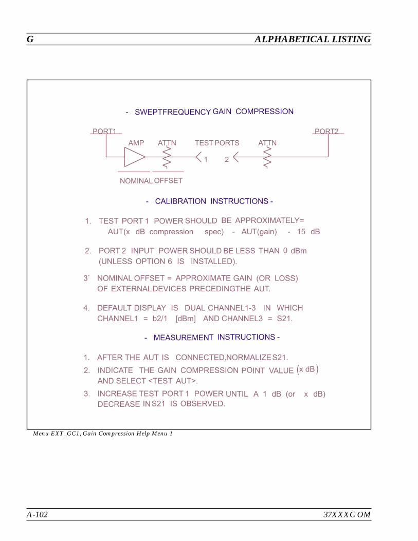
A-102 37XXXC OM
G ALPHABETICAL LISTING
1. TEST PORT 1 POWER SHOULD BE APPROXIMATELY=
AUT(x dB compression spec) - AUT(gain) - 15 dB
2. PORT 2 INPUT POWER SHOULD BE LESS THAN 0 dBm
(UNLESS OPTION 6 IS INSTALLED).
3.
NOMINAL OFFSET = APPROXIMATE GAIN (OR LOSS)
OF EXTERNALDEVICES PRECEDINGTHE AUT.
4. DEFAULT DISPLAY IS DUAL CHANNEL1-3 IN WHICH
CHANNEL1 = b2/1 [dBm] AND CHANNEL3 = S21.
1. AFTER THE AUT IS CONNECTED,NORMALIZES21.
2. INDICATE THE GAIN COMPRESSION POINT VALUE (x dB)AND SELECT <TEST AUT>.
3. INCREASE TEST PORT 1 POWER UNTIL A 1 dB (or x dB)
DECREASE INS21 IS OBSERVED.
PORT1 PORT2
AMP ATTN TEST PORTS ATTN
1 2
NOMINAL OFFSET
- SWEPTFREQUENCY GAIN COMPRESSION-
- CALIBRATION INSTRUCTIONS -
- MEASUREMENT INSTRUCTIONS -
Menu EXT_GC1, Gain Compression Help Menu 1

37XXXC OM A-103
ALPHABETICAL LISTING G
MENU DESCRIPTION GPIB COMMAND
SWEPT POWERGAIN COMPRESSION
None
SET FREQUENCIES Calls menu GC_DF2, with it extended menuEXT_GC_DF2. There the you may enter from 1 to 10discrete frequencies to be used by the application.
None
P START-XX.XX dBm
Defines the power sweep. The start and stop are limitedby the actual power control range of the internal source.The stepsize resolution is limited to 0.05 dB.
PSTRT; PSTRT?
P STOP-XX.XX dBm
PSTOP; PSTOP?
STEPSIZEX.XX dB
PSTEP; PSTEP?
ATTENUATION Calls menu GC_SU2, which lets you set attenuation values. None
GAIN COMPRESSIONPOINT (MAX REF)XX.XX dB
This option is used with marker search functions. Valuehas a range from 0.05 to 9.99 dB and a default value of1.00 dB. The search value is [negative] the gaincompression point value. The reference is based on(maximum) with tracking ON.
GCMP
NOMINAL OFFSET-XX.XX dB
This value is the approximate gain (or loss) of the externaldevices preceding the AUT. Specifically, the gain of theamplifier and attenuator combination. This value is usedwhenever power linearity is turned OFF (while still existing)to prevent an unexpected jump in the power to the AUT.
NOFST; NOFST?
MORE Calls menu GC3, with is companion menu EXT_CG3. None
PRESS <ENTER>TO SELECT
Pressing the Enter key implements your menu selection. None
Menu GC2, Swept Power Gain Compression 1
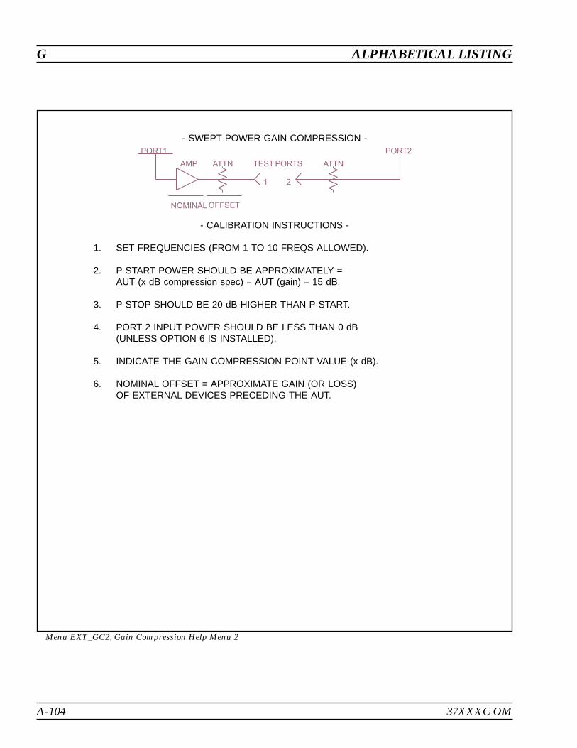
A-104 37XXXC OM
G ALPHABETICAL LISTING
- SWEPT POWER GAIN COMPRESSION -
- CALIBRATION INSTRUCTIONS -
1. SET FREQUENCIES (FROM 1 TO 10 FREQS ALLOWED).
2. P START POWER SHOULD BE APPROXIMATELY =AUT (x dB compression spec) AUT (gain) 15 dB.
3. P STOP SHOULD BE 20 dB HIGHER THAN P START.
4. PORT 2 INPUT POWER SHOULD BE LESS THAN 0 dB(UNLESS OPTION 6 IS INSTALLED).
5. INDICATE THE GAIN COMPRESSION POINT VALUE (x dB).
6. NOMINAL OFFSET = APPROXIMATE GAIN (OR LOSS)OF EXTERNAL DEVICES PRECEDING THE AUT.
Menu EXT_GC2, Gain Compression Help Menu 2
PORT1 PORT2
AMP ATTN TEST PORTS ATTN
1 2
NOMINAL OFFSET
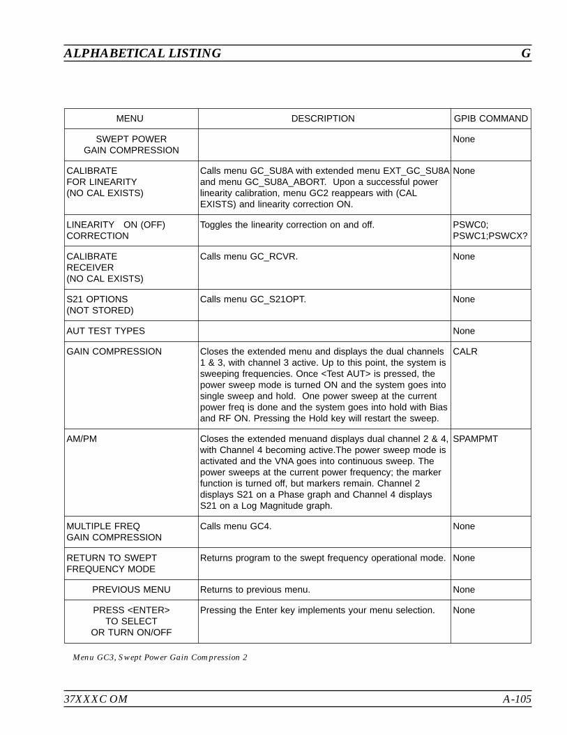
37XXXC OM A-105
ALPHABETICAL LISTING G
MENU DESCRIPTION GPIB COMMAND
SWEPT POWERGAIN COMPRESSION
None
CALIBRATEFOR LINEARITY(NO CAL EXISTS)
Calls menu GC_SU8A with extended menu EXT_GC_SU8Aand menu GC_SU8A_ABORT. Upon a successful powerlinearity calibration, menu GC2 reappears with (CALEXISTS) and linearity correction ON.
None
LINEARITY ON (OFF)CORRECTION
Toggles the linearity correction on and off. PSWC0;PSWC1;PSWCX?
CALIBRATERECEIVER(NO CAL EXISTS)
Calls menu GC_RCVR. None
S21 OPTIONS(NOT STORED)
Calls menu GC_S21OPT. None
AUT TEST TYPES None
GAIN COMPRESSION Closes the extended menu and displays the dual channels1 & 3, with channel 3 active. Up to this point, the system issweeping frequencies. Once <Test AUT> is pressed, thepower sweep mode is turned ON and the system goes intosingle sweep and hold. One power sweep at the currentpower freq is done and the system goes into hold with Biasand RF ON. Pressing the Hold key will restart the sweep.
CALR
AM/PM Closes the extended menuand displays dual channel 2 & 4,with Channel 4 becoming active.The power sweep mode isactivated and the VNA goes into continuous sweep. Thepower sweeps at the current power frequency; the markerfunction is turned off, but markers remain. Channel 2displays S21 on a Phase graph and Channel 4 displaysS21 on a Log Magnitude graph.
SPAMPMT
MULTIPLE FREQGAIN COMPRESSION
Calls menu GC4. None
RETURN TO SWEPTFREQUENCY MODE
Returns program to the swept frequency operational mode. None
PREVIOUS MENU Returns to previous menu. None
PRESS <ENTER>TO SELECT
OR TURN ON/OFF
Pressing the Enter key implements your menu selection. None
Menu GC3, Swept Power Gain Compression 2

A-106 37XXXC OM
G ALPHABETICAL LISTING
- SWEPT POWER GAIN COMPRESSION -
- CALIBRATION INSTRUCTIONS -
7. LINEARITY CALIBRATION IMPROVES ACCURACY.
8. RECEIVER CALIBRATION IS DONE AT P STOP.NORMALIZE S21 AND DISPLAY S21 ARE IS DONE AT P START.
9. DEFAULT DISPLAY IS DUAL CHANNEL 1-3 IN WHICHCHANNEL 1 = b2/1 [dBm] AND CHANNEL 3 = S21
-MEASUREMENT INSTRUCTIONS-
1. SELECT THE DESIRED S21 OPTION.
2. SELECT <GAIN COMPRESSION> OR <AM/PM> AUT TEST.
3. MARKERS CAN BE USED TO LOCATE THE 1 dB (or x dB)COMPRESSION POINT. CHANGE THE POWER FREQUENCY TOMEASURE EACH OF THE OTHER POWER SWEEPS.
4. SELECT <MULTIPLE FREQ GAIN COMPRESSION> TO TESTTHE AUT AT ALL THE SWEPT POWER FREQUENCIES. THERESULTS ARE COMPUTED UNDER THE ASSUMPTION THATP OUTPUT AT P START IS IN THE AUT’S LINEAR REGION.
Menu EXT_GC3, Gain Compression Help Menu 3
PORT1 PORT2
AMP ATTN TEST PORTS ATTN
1 2
NOMINAL OFFSET
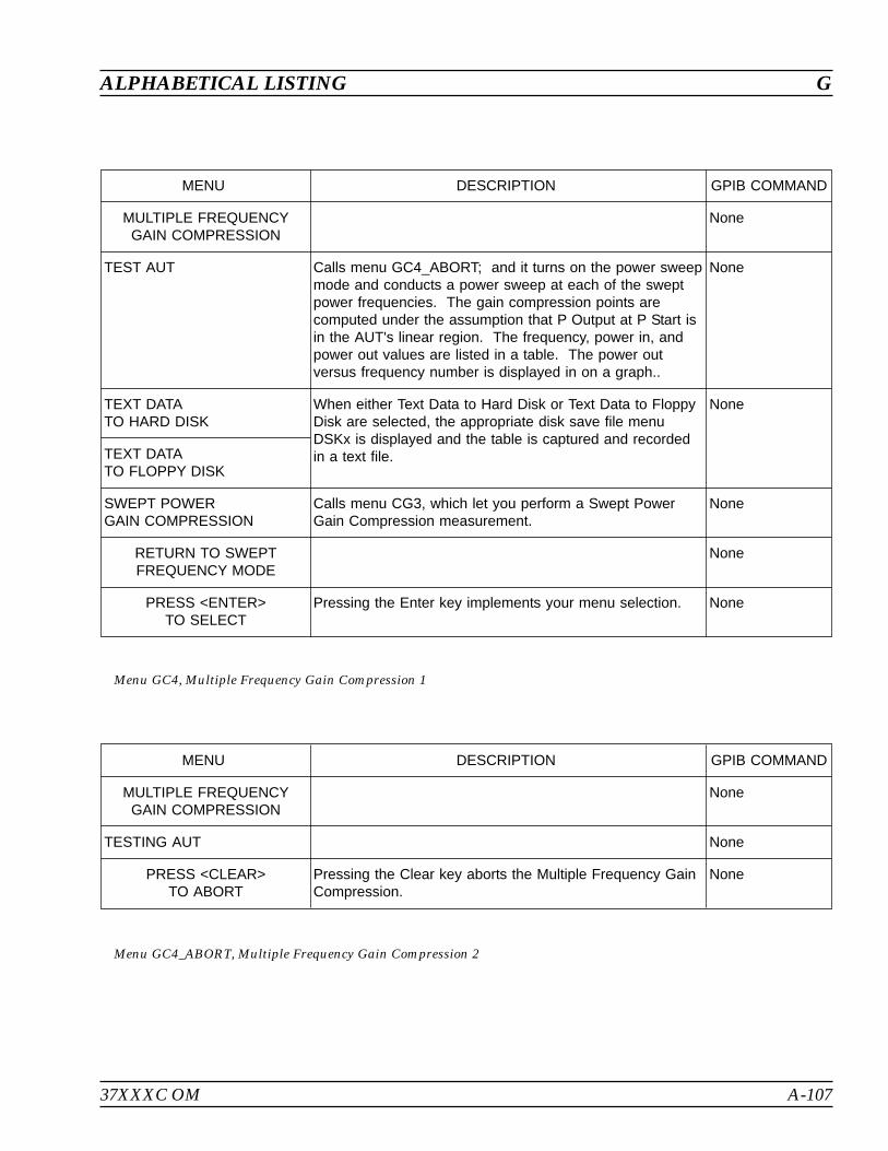
37XXXC OM A-107
ALPHABETICAL LISTING G
MENU DESCRIPTION GPIB COMMAND
MULTIPLE FREQUENCYGAIN COMPRESSION
None
TEST AUT Calls menu GC4_ABORT; and it turns on the power sweepmode and conducts a power sweep at each of the sweptpower frequencies. The gain compression points arecomputed under the assumption that P Output at P Start isin the AUT's linear region. The frequency, power in, andpower out values are listed in a table. The power outversus frequency number is displayed in on a graph..
None
TEXT DATATO HARD DISK
When either Text Data to Hard Disk or Text Data to FloppyDisk are selected, the appropriate disk save file menuDSKx is displayed and the table is captured and recordedin a text file.
None
TEXT DATATO FLOPPY DISK
SWEPT POWERGAIN COMPRESSION
Calls menu CG3, which let you perform a Swept PowerGain Compression measurement.
None
RETURN TO SWEPTFREQUENCY MODE
None
PRESS <ENTER>TO SELECT
Pressing the Enter key implements your menu selection. None
Menu GC4, Multiple Frequency Gain Compression 1
MENU DESCRIPTION GPIB COMMAND
MULTIPLE FREQUENCYGAIN COMPRESSION
None
TESTING AUT None
PRESS <CLEAR>TO ABORT
Pressing the Clear key aborts the Multiple Frequency GainCompression.
None
Menu GC4_ABORT, Multiple Frequency Gain Compression 2
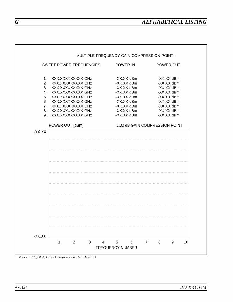
A-108 37XXXC OM
G ALPHABETICAL LISTING
- MULTIPLE FREQUENCY GAIN COMPRESSION POINT -
SWEPT POWER FREQUENCIES POWER IN POWER OUT
1. XXX.XXXXXXXXX GHz -XX.XX dBm -XX.XX dBm2. XXX.XXXXXXXXX GHz -XX.XX dBm -XX.XX dBm3. XXX.XXXXXXXXX GHz -XX.XX dBm -XX.XX dBm4. XXX.XXXXXXXXX GHz -XX.XX dBm -XX.XX dBm5. XXX.XXXXXXXXX GHz -XX.XX dBm -XX.XX dBm6. XXX.XXXXXXXXX GHz -XX.XX dBm -XX.XX dBm7. XXX.XXXXXXXXX GHz -XX.XX dBm -XX.XX dBm8. XXX.XXXXXXXXX GHz -XX.XX dBm -XX.XX dBm9. XXX.XXXXXXXXX GHz -XX.XX dBm -XX.XX dBm
Menu EXT_GC4, Gain Compression Help Menu 4
1 2 3 4 5 6 7 8 9 10
-XX.XX
-XX.XX
POWER OUT [dBm] 1.00 dB GAIN COMPRESSION POINT
FREQUENCY NUMBER

37XXXC OM A-109
ALPHABETICAL LISTING G
MENU DESCRIPTION GPIB COMMAND
SWEPT POWERFREQUENCIES
None
INPUT A FREQ,PRESS <ENTER>TO INSERT
This menu performs in a similar manner to the menu DF2,Insert Individual Frequencies. The list is updated and keptin ascending order. Any frequencies which are added ordeleted force a resorting of the list. The user can enterfrom 1 to 10 swept power frequencies.
None
SWEPT POWERFREQUENCYXXX.XXXXXXXXX GHz
Enter the swept power frequencies using the keypad orknob. Press <ENTER> to insert into the swept powerfrequency list
CLEAR FREQ NUMBERXX
Enter the number of the frequency to remove from the listusing the keypad or knob. Press <ENTER> to remove theselection from the list.
CLEAR ALL Press <ENTER> to remove all the frequencies from theswept power frequency list.
FINISHED,RETURN TO POWERSWEEP SETUP
After the swept power frequency list is entered, this returnsto menu GC2.
None
PRESS <ENTER>TO SELECT
Pressing the Enter key implements your menu selection. None
Menu GC_DF2, Swept Power Frequencies
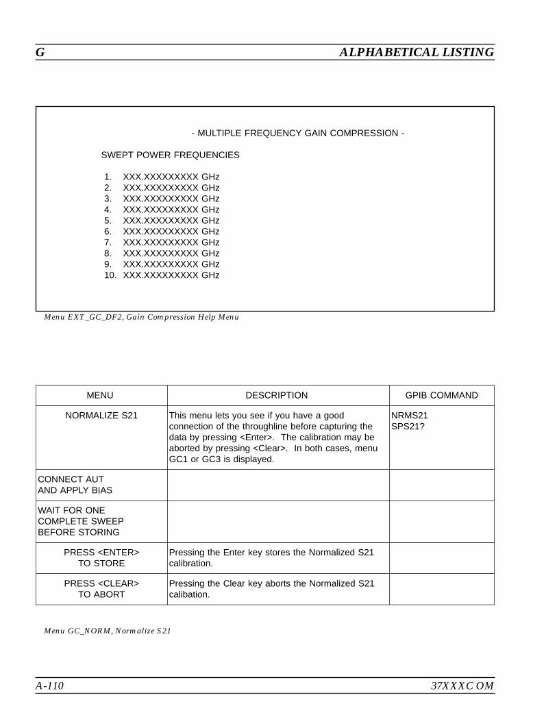
A-110 37XXXC OM
G ALPHABETICAL LISTING
- MULTIPLE FREQUENCY GAIN COMPRESSION -
SWEPT POWER FREQUENCIES
1. XXX.XXXXXXXXX GHz2. XXX.XXXXXXXXX GHz3. XXX.XXXXXXXXX GHz4. XXX.XXXXXXXXX GHz5. XXX.XXXXXXXXX GHz6. XXX.XXXXXXXXX GHz7. XXX.XXXXXXXXX GHz8. XXX.XXXXXXXXX GHz9. XXX.XXXXXXXXX GHz10. XXX.XXXXXXXXX GHz
Menu EXT_GC_DF2, Gain Compression Help Menu
MENU DESCRIPTION GPIB COMMAND
NORMALIZE S21 This menu lets you see if you have a goodconnection of the throughline before capturing thedata by pressing <Enter>. The calibration may beaborted by pressing <Clear>. In both cases, menuGC1 or GC3 is displayed.
NRMS21SPS21?
CONNECT AUTAND APPLY BIAS
WAIT FOR ONECOMPLETE SWEEPBEFORE STORING
PRESS <ENTER>TO STORE
Pressing the Enter key stores the Normalized S21calibration.
PRESS <CLEAR>TO ABORT
Pressing the Clear key aborts the Normalized S21calibation.
Menu GC_NORM, Normalize S21

37XXXC OM A-111
ALPHABETICAL LISTING G
MENU DESCRIPTION GPIB COMMAND
RECEIVERCALIBRATION
This menu lets you see if you have a good connection ofthe throughline before capturing the data by pressing<Enter>. The calibration may be aborted by pressing<Clear>. In both cases, menu GC1 or GC2 is displayed.
None
CONNECTTHROUGHLINEBETWEENTEST PORTS
None
INCLUDE ANYCOMPONENTS WHICHARE PART OF THEMEASUREMENT PATH
None
WAIT FOR ONECOMPLETE SWEEPBEFORE STORING
CALR
PRESS <ENTER>TO STORE
Pressing the Enter key stores the receiver calibration. None
PRESS <CLEAR>TO ABORT
Pressing the Clear key aborts the Receiver calibation. None
Menu GC_RCVR, Receiver Calibration
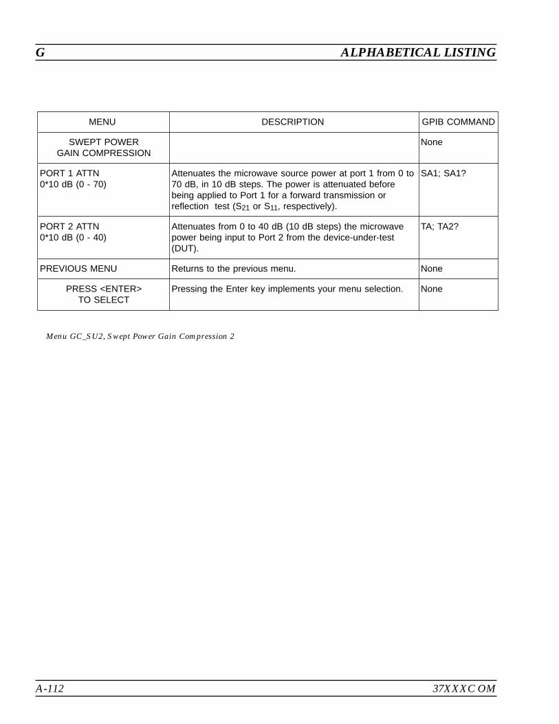
A-112 37XXXC OM
G ALPHABETICAL LISTING
MENU DESCRIPTION GPIB COMMAND
SWEPT POWERGAIN COMPRESSION
None
PORT 1 ATTN0*10 dB (0 - 70)
Attenuates the microwave source power at port 1 from 0 to70 dB, in 10 dB steps. The power is attenuated beforebeing applied to Port 1 for a forward transmission orreflection test (S21 or S11, respectively).
SA1; SA1?
PORT 2 ATTN0*10 dB (0 - 40)
Attenuates from 0 to 40 dB (10 dB steps) the microwavepower being input to Port 2 from the device-under-test(DUT).
TA; TA2?
PREVIOUS MENU Returns to the previous menu. None
PRESS <ENTER>TO SELECT
Pressing the Enter key implements your menu selection. None
Menu GC_SU2, Swept Power Gain Compression 2
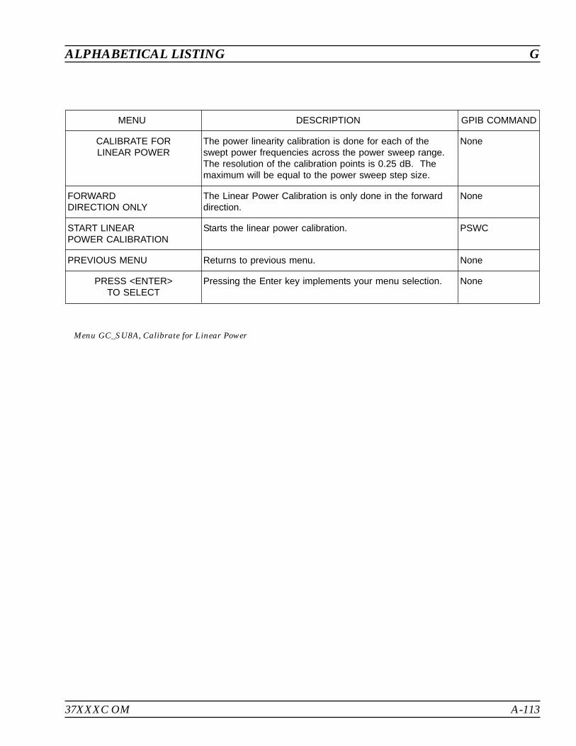
37XXXC OM A-113
ALPHABETICAL LISTING G
MENU DESCRIPTION GPIB COMMAND
CALIBRATE FORLINEAR POWER
The power linearity calibration is done for each of theswept power frequencies across the power sweep range.The resolution of the calibration points is 0.25 dB. Themaximum will be equal to the power sweep step size.
None
FORWARDDIRECTION ONLY
The Linear Power Calibration is only done in the forwarddirection.
None
START LINEARPOWER CALIBRATION
Starts the linear power calibration. PSWC
PREVIOUS MENU Returns to previous menu. None
PRESS <ENTER>TO SELECT
Pressing the Enter key implements your menu selection. None
Menu GC_SU8A, Calibrate for Linear Power
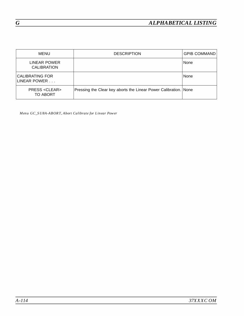
A-114 37XXXC OM
G ALPHABETICAL LISTING
MENU DESCRIPTION GPIB COMMAND
LINEAR POWERCALIBRATION
None
CALIBRATING FORLINEAR POWER . . .
None
PRESS <CLEAR>TO ABORT
Pressing the Clear key aborts the Linear Power Calibration. None
Menu GC_SU8A-ABORT, Abort Calibrate for Linear Power

37XXXC OM A-115
ALPHABETICAL LISTING G
- LINEAR POWER CALIBRATION -
- CALIBRATION INSTRUCTIONS -
LINEAR POWER CALIBRATION ADJUSTS THE SOURCE OUTPUTPOWER FOR EACH POWER FREQUENCY POINT ACROSS THE POWERSWEEP RANGE TO PROVIDE A LINEAR POWER LEVEL AT THETEST PORT (FORWARD DIRECTION ONLY).
- INSTRUCTIONS -
1. PRESET, ZERO, AND CALIBRATE THE POWER METER.
2. CREATE AND ACTIVATE THE POWER METER'S CALFACTOR LIST FOR THE POWER SENSOR BEING USED.
3. CONNECT THE POWER METER TO THE DEDICATED GPIBINTERFACE AND THE POWER SENSOR TO THE TEST PORT.
4. SELECT <START LINEAR POWER CALIBRATION>.
Menu EXT_GC_SU8A, Gain Compression Help Menu
XXX.X%
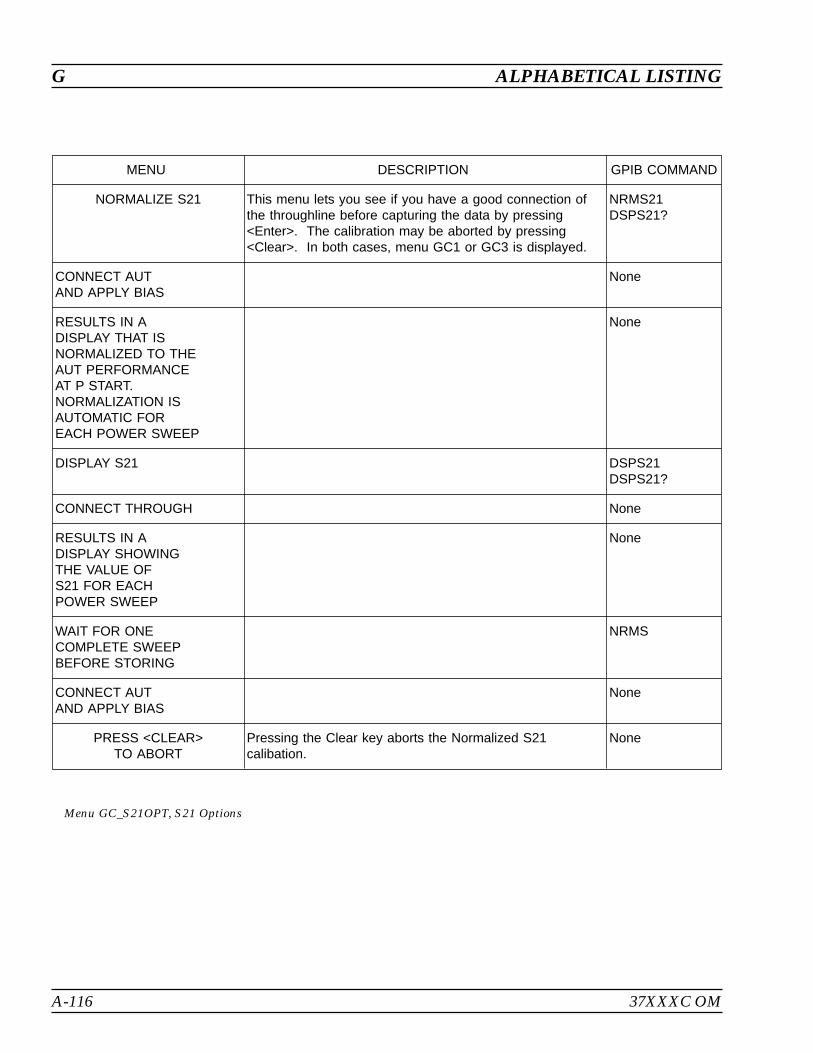
A-116 37XXXC OM
G ALPHABETICAL LISTING
MENU DESCRIPTION GPIB COMMAND
NORMALIZE S21 This menu lets you see if you have a good connection ofthe throughline before capturing the data by pressing<Enter>. The calibration may be aborted by pressing<Clear>. In both cases, menu GC1 or GC3 is displayed.
NRMS21DSPS21?
CONNECT AUTAND APPLY BIAS
None
RESULTS IN ADISPLAY THAT ISNORMALIZED TO THEAUT PERFORMANCEAT P START.NORMALIZATION ISAUTOMATIC FOREACH POWER SWEEP
None
DISPLAY S21 DSPS21DSPS21?
CONNECT THROUGH None
RESULTS IN ADISPLAY SHOWINGTHE VALUE OFS21 FOR EACHPOWER SWEEP
None
WAIT FOR ONECOMPLETE SWEEPBEFORE STORING
NRMS
CONNECT AUTAND APPLY BIAS
None
PRESS <CLEAR>TO ABORT
Pressing the Clear key aborts the Normalized S21calibation.
None
Menu GC_S21OPT, S21 Options
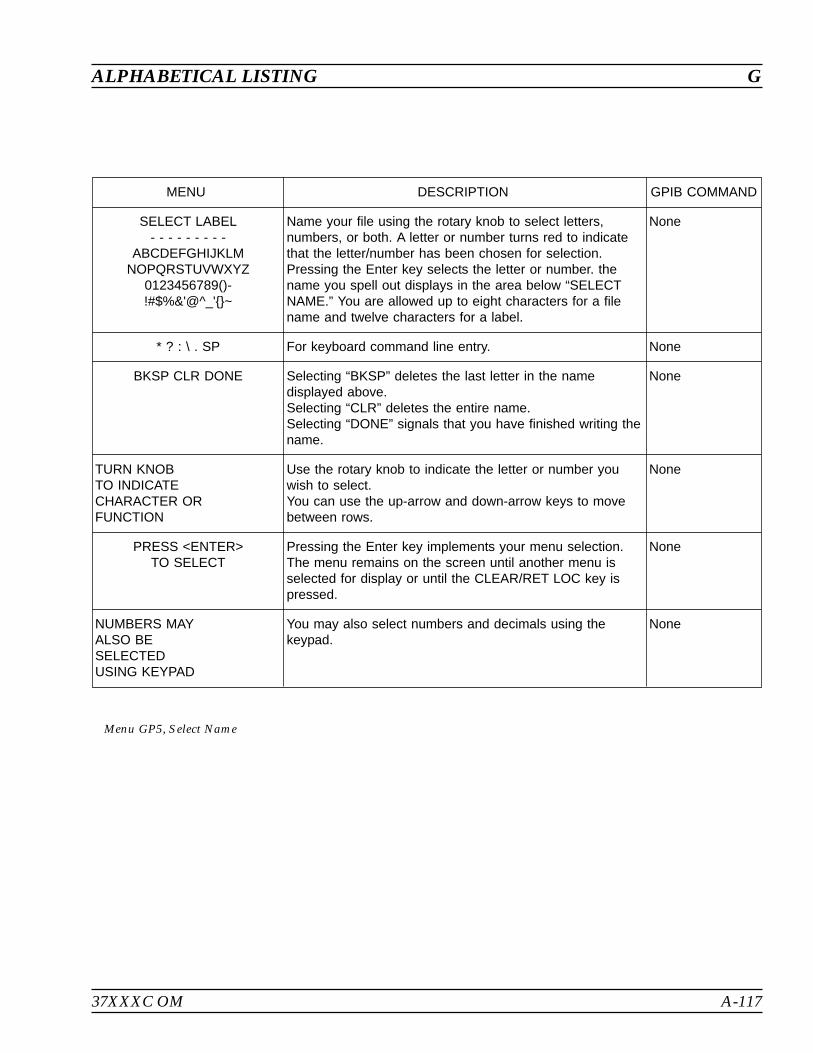
37XXXC OM A-117
ALPHABETICAL LISTING G
MENU DESCRIPTION GPIB COMMAND
SELECT LABEL- - - - - - - - -
ABCDEFGHIJKLMNOPQRSTUVWXYZ
0123456789()-!#$%&'@^_'~
Name your file using the rotary knob to select letters,numbers, or both. A letter or number turns red to indicatethat the letter/number has been chosen for selection.Pressing the Enter key selects the letter or number. thename you spell out displays in the area below “SELECTNAME.” You are allowed up to eight characters for a filename and twelve characters for a label.
None
* ? : \ . SP For keyboard command line entry. None
BKSP CLR DONE Selecting “BKSP” deletes the last letter in the namedisplayed above.Selecting “CLR” deletes the entire name.Selecting “DONE” signals that you have finished writing thename.
None
TURN KNOBTO INDICATECHARACTER ORFUNCTION
Use the rotary knob to indicate the letter or number youwish to select.You can use the up-arrow and down-arrow keys to movebetween rows.
None
PRESS <ENTER>TO SELECT
Pressing the Enter key implements your menu selection.The menu remains on the screen until another menu isselected for display or until the CLEAR/RET LOC key ispressed.
None
NUMBERS MAYALSO BESELECTEDUSING KEYPAD
You may also select numbers and decimals using thekeypad.
None
Menu GP5, Select Name
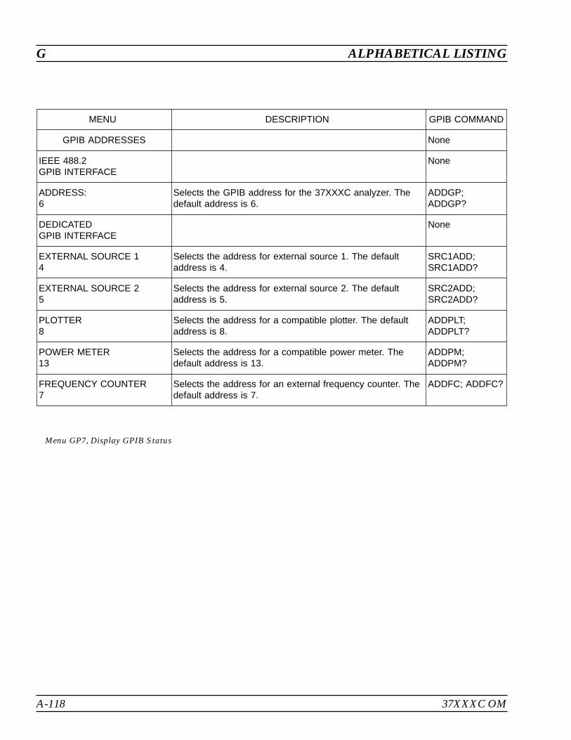
A-118 37XXXC OM
G ALPHABETICAL LISTING
MENU DESCRIPTION GPIB COMMAND
GPIB ADDRESSES None
IEEE 488.2GPIB INTERFACE
None
ADDRESS:6
Selects the GPIB address for the 37XXXC analyzer. Thedefault address is 6.
ADDGP;ADDGP?
DEDICATEDGPIB INTERFACE
None
EXTERNAL SOURCE 14
Selects the address for external source 1. The defaultaddress is 4.
SRC1ADD;SRC1ADD?
EXTERNAL SOURCE 25
Selects the address for external source 2. The defaultaddress is 5.
SRC2ADD;SRC2ADD?
PLOTTER8
Selects the address for a compatible plotter. The defaultaddress is 8.
ADDPLT;ADDPLT?
POWER METER13
Selects the address for a compatible power meter. Thedefault address is 13.
ADDPM;ADDPM?
FREQUENCY COUNTER7
Selects the address for an external frequency counter. Thedefault address is 7.
ADDFC; ADDFC?
Menu GP7, Display GPIB Status

37XXXC OM A-119
ALPHABETICAL LISTING G
MENU DESCRIPTION GPIB COMMAND
SELECTGRAPH TYPE
None
LOG MAGNITUDE Selects a log magnitude graph for display on the activechannel's selected S-parameter. The active channel isindicated by its key (CH1, CH2, CH3, CH4) being lit.
MAG
PHASE Selects a phase graph for display on the active channel. PHA
LOG MAGNITUDEAND PHASE
Selects log magnitude and phase graphs for display on theactive channel.
MPH
SMITH CHART(IMPEDANCE)
Selects a Smith chart for display on the active channel. SMI; SME; SMC
SWR Selects an SWR display for the active channel. SWR
GROUP DELAY Selects a Group Delay display for the active channel. DLA
POWER OUT Provides for measuring output power. The measurement ofoutput power is accomplished by using the b2 (or Tb)measured value normalized to the power supplied to theAUT at Test Port 1. While the b2 parameter is the mostmeaningful for this graph type, you may use any otherparameter.
POW
MORE Calls additional graph type selections on menu GT2. None
PRESS <ENTER>TO SELECT
AND RESUME CAL
Pressing the Enter key implements your menu selection(and resumes the calibration from where it left off, if in thecalibration mode).
None
Menu GT1/CAL_GT1, Select Graph Type
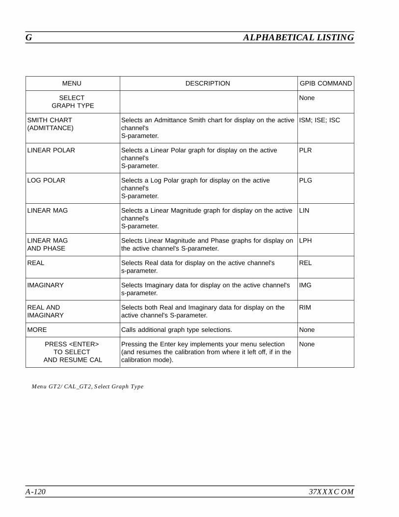
A-120 37XXXC OM
G ALPHABETICAL LISTING
MENU DESCRIPTION GPIB COMMAND
SELECTGRAPH TYPE
None
SMITH CHART(ADMITTANCE)
Selects an Admittance Smith chart for display on the activechannel'sS-parameter.
ISM; ISE; ISC
LINEAR POLAR Selects a Linear Polar graph for display on the activechannel'sS-parameter.
PLR
LOG POLAR Selects a Log Polar graph for display on the activechannel'sS-parameter.
PLG
LINEAR MAG Selects a Linear Magnitude graph for display on the activechannel'sS-parameter.
LIN
LINEAR MAGAND PHASE
Selects Linear Magnitude and Phase graphs for display onthe active channel's S-parameter.
LPH
REAL Selects Real data for display on the active channel'ss-parameter.
REL
IMAGINARY Selects Imaginary data for display on the active channel'ss-parameter.
IMG
REAL ANDIMAGINARY
Selects both Real and Imaginary data for display on theactive channel's S-parameter.
RIM
MORE Calls additional graph type selections. None
PRESS <ENTER>TO SELECT
AND RESUME CAL
Pressing the Enter key implements your menu selection(and resumes the calibration from where it left off, if in thecalibration mode).
None
Menu GT2/CAL_GT2, Select Graph Type
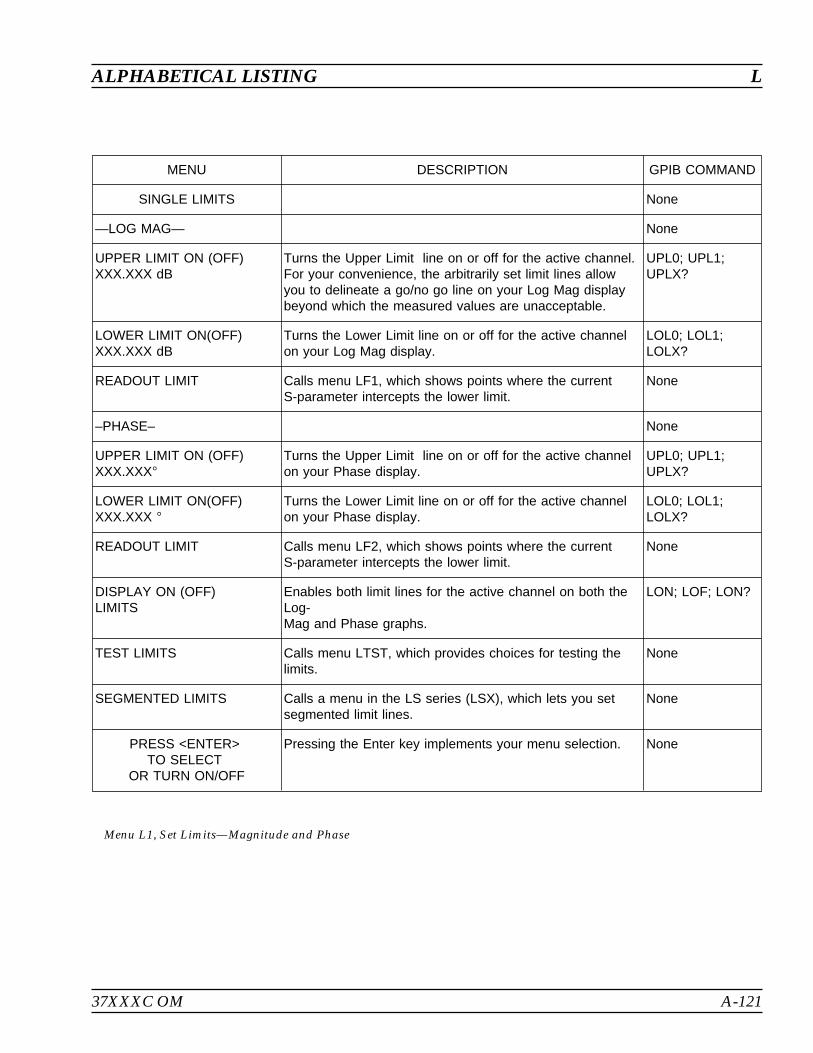
37XXXC OM A-121
ALPHABETICAL LISTING L
MENU DESCRIPTION GPIB COMMAND
SINGLE LIMITS None
—LOG MAG— None
UPPER LIMIT ON (OFF)XXX.XXX dB
Turns the Upper Limit line on or off for the active channel.For your convenience, the arbitrarily set limit lines allowyou to delineate a go/no go line on your Log Mag displaybeyond which the measured values are unacceptable.
UPL0; UPL1;UPLX?
LOWER LIMIT ON(OFF)XXX.XXX dB
Turns the Lower Limit line on or off for the active channelon your Log Mag display.
LOL0; LOL1;LOLX?
READOUT LIMIT Calls menu LF1, which shows points where the currentS-parameter intercepts the lower limit.
None
–PHASE– None
UPPER LIMIT ON (OFF)XXX.XXX
Turns the Upper Limit line on or off for the active channelon your Phase display.
UPL0; UPL1;UPLX?
LOWER LIMIT ON(OFF)XXX.XXX
Turns the Lower Limit line on or off for the active channelon your Phase display.
LOL0; LOL1;LOLX?
READOUT LIMIT Calls menu LF2, which shows points where the currentS-parameter intercepts the lower limit.
None
DISPLAY ON (OFF)LIMITS
Enables both limit lines for the active channel on both theLog-Mag and Phase graphs.
LON; LOF; LON?
TEST LIMITS Calls menu LTST, which provides choices for testing thelimits.
None
SEGMENTED LIMITS Calls a menu in the LS series (LSX), which lets you setsegmented limit lines.
None
PRESS <ENTER>TO SELECT
OR TURN ON/OFF
Pressing the Enter key implements your menu selection. None
Menu L1, Set Limits—Magnitude and Phase
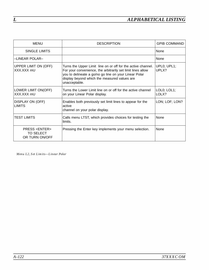
A-122 37XXXC OM
L ALPHABETICAL LISTING
MENU DESCRIPTION GPIB COMMAND
SINGLE LIMITS None
–LINEAR POLAR– None
UPPER LIMIT ON (OFF)XXX.XXX mU
Turns the Upper Limit line on or off for the active channel.For your convenience, the arbitrarily set limit lines allowyou to delineate a go/no go line on your Linear Polardisplay beyond which the measured values areunacceptable.
UPL0; UPL1;UPLX?
LOWER LIMIT ON(OFF)XXX.XXX mU
Turns the Lower Limit line on or off for the active channelon your Linear Polar display.
LOL0; LOL1;LOLX?
DISPLAY ON (OFF)LIMITS
Enables both previously set limit lines to appear for theactivechannel on your polar display.
LON; LOF; LON?
TEST LIMITS Calls menu LTST, which provides choices for testing thelimits.
None
PRESS <ENTER>TO SELECT
OR TURN ON/OFF
Pressing the Enter key implements your menu selection. None
Menu L2, Set Limits—Linear Polar
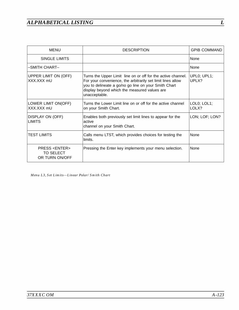
37XXXC OM A-123
ALPHABETICAL LISTING L
MENU DESCRIPTION GPIB COMMAND
SINGLE LIMITS None
–SMITH CHART– None
UPPER LIMIT ON (OFF)XXX.XXX mU
Turns the Upper Limit line on or off for the active channel.For your convenience, the arbitrarily set limit lines allowyou to delineate a go/no go line on your Smith Chartdisplay beyond which the measured values areunacceptable.
UPL0; UPL1;UPLX?
LOWER LIMIT ON(OFF)XXX.XXX mU
Turns the Lower Limit line on or off for the active channelon your Smith Chart.
LOL0; LOL1;LOLX?
DISPLAY ON (OFF)LIMITS
Enables both previously set limit lines to appear for theactivechannel on your Smith Chart.
LON; LOF; LON?
TEST LIMITS Calls menu LTST, which provides choices for testing thelimits.
None
PRESS <ENTER>TO SELECT
OR TURN ON/OFF
Pressing the Enter key implements your menu selection. None
Menu L3, Set Limits—Linear Polar/Smith Chart
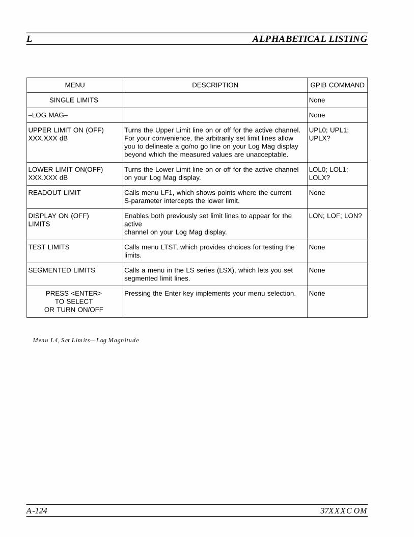
A-124 37XXXC OM
L ALPHABETICAL LISTING
MENU DESCRIPTION GPIB COMMAND
SINGLE LIMITS None
–LOG MAG– None
UPPER LIMIT ON (OFF)XXX.XXX dB
Turns the Upper Limit line on or off for the active channel.For your convenience, the arbitrarily set limit lines allowyou to delineate a go/no go line on your Log Mag displaybeyond which the measured values are unacceptable.
UPL0; UPL1;UPLX?
LOWER LIMIT ON(OFF)XXX.XXX dB
Turns the Lower Limit line on or off for the active channelon your Log Mag display.
LOL0; LOL1;LOLX?
READOUT LIMIT Calls menu LF1, which shows points where the currentS-parameter intercepts the lower limit.
None
DISPLAY ON (OFF)LIMITS
Enables both previously set limit lines to appear for theactivechannel on your Log Mag display.
LON; LOF; LON?
TEST LIMITS Calls menu LTST, which provides choices for testing thelimits.
None
SEGMENTED LIMITS Calls a menu in the LS series (LSX), which lets you setsegmented limit lines.
None
PRESS <ENTER>TO SELECT
OR TURN ON/OFF
Pressing the Enter key implements your menu selection. None
Menu L4, Set Limits—Log Magnitude
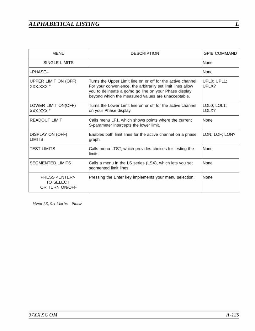
37XXXC OM A-125
ALPHABETICAL LISTING L
MENU DESCRIPTION GPIB COMMAND
SINGLE LIMITS None
–PHASE– None
UPPER LIMIT ON (OFF)XXX.XXX
Turns the Upper Limit line on or off for the active channel.For your convenience, the arbitrarily set limit lines allowyou to delineate a go/no go line on your Phase displaybeyond which the measured values are unacceptable.
UPL0; UPL1;UPLX?
LOWER LIMIT ON(OFF)XXX.XXX
Turns the Lower Limit line on or off for the active channelon your Phase display.
LOL0; LOL1;LOLX?
READOUT LIMIT Calls menu LF1, which shows points where the currentS-parameter intercepts the lower limit.
None
DISPLAY ON (OFF)LIMITS
Enables both limit lines for the active channel on a phasegraph.
LON; LOF; LON?
TEST LIMITS Calls menu LTST, which provides choices for testing thelimits.
None
SEGMENTED LIMITS Calls a menu in the LS series (LSX), which lets you setsegmented limit lines.
None
PRESS <ENTER>TO SELECT
OR TURN ON/OFF
Pressing the Enter key implements your menu selection. None
Menu L5, Set Limits—Phase
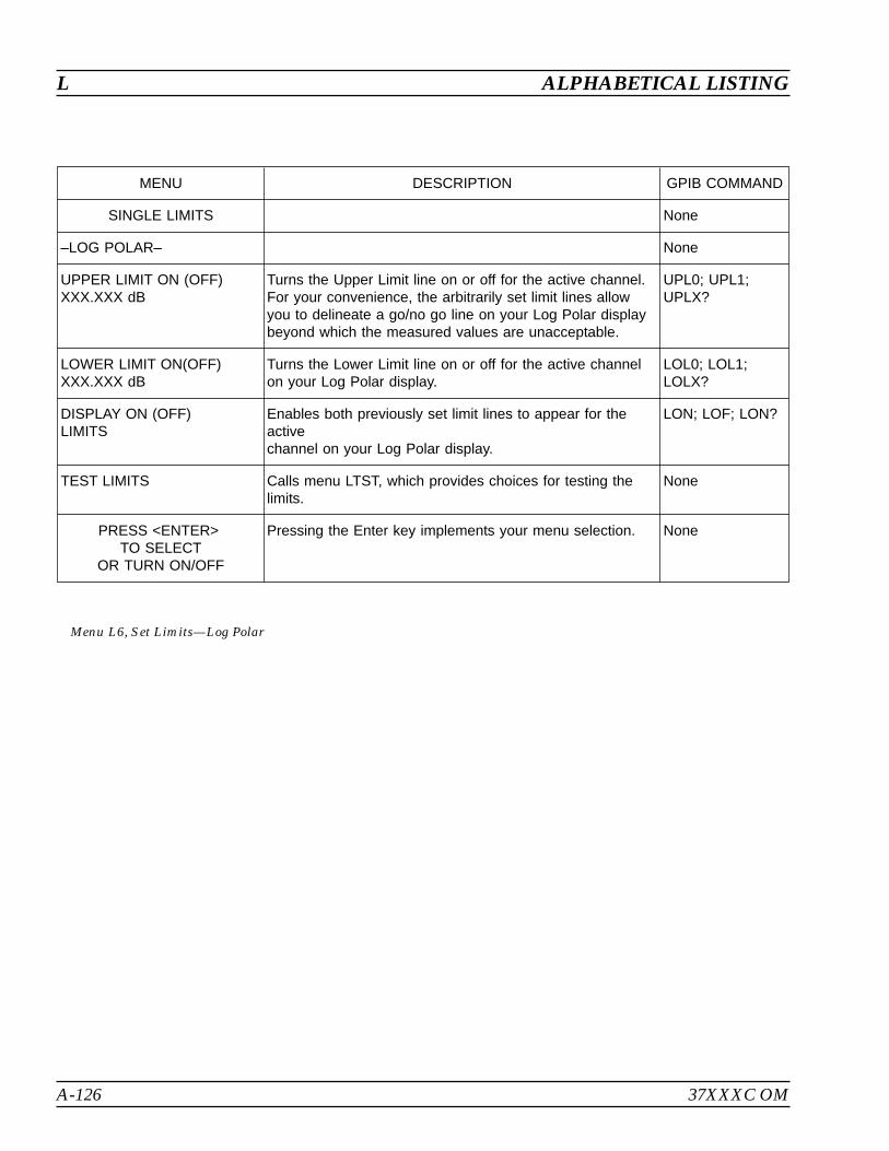
A-126 37XXXC OM
L ALPHABETICAL LISTING
MENU DESCRIPTION GPIB COMMAND
SINGLE LIMITS None
–LOG POLAR– None
UPPER LIMIT ON (OFF)XXX.XXX dB
Turns the Upper Limit line on or off for the active channel.For your convenience, the arbitrarily set limit lines allowyou to delineate a go/no go line on your Log Polar displaybeyond which the measured values are unacceptable.
UPL0; UPL1;UPLX?
LOWER LIMIT ON(OFF)XXX.XXX dB
Turns the Lower Limit line on or off for the active channelon your Log Polar display.
LOL0; LOL1;LOLX?
DISPLAY ON (OFF)LIMITS
Enables both previously set limit lines to appear for theactivechannel on your Log Polar display.
LON; LOF; LON?
TEST LIMITS Calls menu LTST, which provides choices for testing thelimits.
None
PRESS <ENTER>TO SELECT
OR TURN ON/OFF
Pressing the Enter key implements your menu selection. None
Menu L6, Set Limits—Log Polar
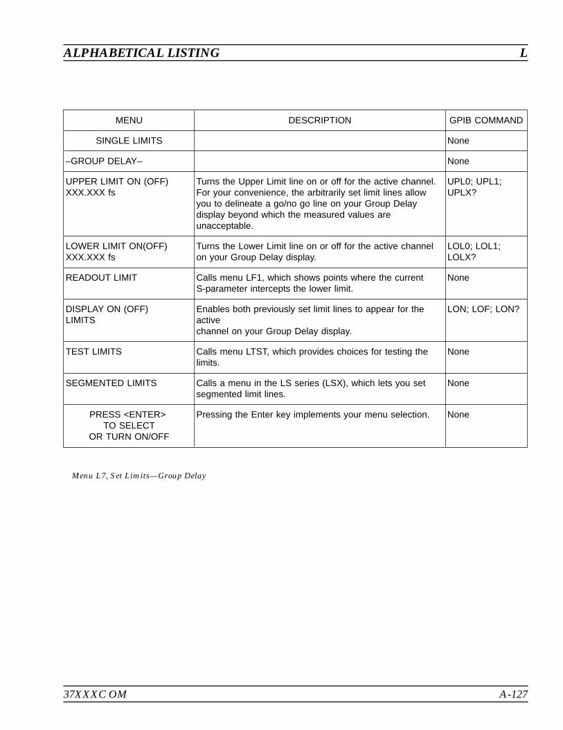
37XXXC OM A-127
ALPHABETICAL LISTING L
MENU DESCRIPTION GPIB COMMAND
SINGLE LIMITS None
–GROUP DELAY– None
UPPER LIMIT ON (OFF)XXX.XXX fs
Turns the Upper Limit line on or off for the active channel.For your convenience, the arbitrarily set limit lines allowyou to delineate a go/no go line on your Group Delaydisplay beyond which the measured values areunacceptable.
UPL0; UPL1;UPLX?
LOWER LIMIT ON(OFF)XXX.XXX fs
Turns the Lower Limit line on or off for the active channelon your Group Delay display.
LOL0; LOL1;LOLX?
READOUT LIMIT Calls menu LF1, which shows points where the currentS-parameter intercepts the lower limit.
None
DISPLAY ON (OFF)LIMITS
Enables both previously set limit lines to appear for theactivechannel on your Group Delay display.
LON; LOF; LON?
TEST LIMITS Calls menu LTST, which provides choices for testing thelimits.
None
SEGMENTED LIMITS Calls a menu in the LS series (LSX), which lets you setsegmented limit lines.
None
PRESS <ENTER>TO SELECT
OR TURN ON/OFF
Pressing the Enter key implements your menu selection. None
Menu L7, Set Limits—Group Delay

A-128 37XXXC OM
L ALPHABETICAL LISTING
MENU DESCRIPTION GPIB COMMAND
SINGLE LIMITS None
–LINEAR MAG– None
UPPER LIMIT ON (OFF)XXX.XXX pU
Turns the Upper Limit line on or off for the active channel.For your convenience, the arbitrarily set limit lines allowyou to delineate a go/no go line on your Linear Mag displaybeyond which the measured values are unacceptable.
UPL0; UPL1;UPLX?
LOWER LIMIT ON(OFF)XXX.XXX pU
Turns the Lower Limit line on or off for the active channelon your Linear Mag display.
LOL0; LOL1;LOLX?
READOUT LIMIT Calls menu LF1, which shows points where the currentS-parameter intercepts the lower limit.
None
DISPLAY ON (OFF)LIMITS
Enables both previously set limit lines to appear for theactivechannel on your Linear Mag display.
LON; LOF; LON?
TEST LIMITS Calls menu LTST, which provides choices for testing thelimits.
None
SEGMENTED LIMITS Calls a menu in the LS series (LSX), which lets you setsegmented limit lines.
None
PRESS <ENTER>TO SELECT
OR TURN ON/OFF
Pressing the Enter key implements your menu selection. None
Menu L8, Set Limits—Linear Magnitude

37XXXC OM A-129
ALPHABETICAL LISTING L
MENU DESCRIPTION GPIB COMMAND
SINGLE LIMITS None
–LINEAR MAG– None
UPPER LIMIT ON (OFF)XXX.XXX pU
Turns the Upper Limit line on or off for the active channel.For your convenience, the arbitrarily set limit lines allowyou to delineate a go/no go line on your Linear Mag displaybeyond which the measured values are unacceptable.
UPL0; UPL1;UPLX?
LOWER LIMIT ON(OFF)XXX.XXX pU
Turns the Lower Limit line on or off for the active channelon your Linear Mag display.
LOL0; LOL1;LOLX?
READOUT LIMIT Calls menu LF4, which shows points where the currentS-parameter intercepts the lower limit.
None
-PHASE- None
UPPER LIMIT ON (OFF)XXX.XXX
Turns the Upper Limit line on or off for the active channel.For your convenience, the arbitrarily set limit lines allowyou to delineate a go/no go line on your polar displaybeyond which the measured values are unacceptable.
UPL0; UPL1;UPLX?
LOWER LIMIT ON(OFF)XXX.XXX
Turns the Lower Limit line on or off for the active channelon your Phase display.
LOL0; LOL1;LOLX?
READOUT LIMIT Calls menu LF2, which shows points where the currentS-parameter intercepts the lower limit.
None
DISPLAY ON (OFF)LIMITS
Enables both previously set limit lines to appear for theactivechannel on your Phase display.
LON; LOF; LON?
TEST LIMITS Calls menu LTST, which provides choices for testing thelimits.
None
SEGMENTED LIMITS Calls a menu in the LS series (LSX), which lets you setsegmented limit lines.
None
PRESS <ENTER>TO SELECT
OR TURN ON/OFF
Pressing the Enter key implements your menu selection. None
Menu L9, Set Limits—Linear Magnitude and Phase
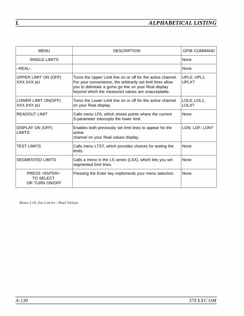
A-130 37XXXC OM
L ALPHABETICAL LISTING
MENU DESCRIPTION GPIB COMMAND
SINGLE LIMITS None
–REAL– None
UPPER LIMIT ON (OFF)XXX.XXX pU
Turns the Upper Limit line on or off for the active channel.For your convenience, the arbitrarily set limit lines allowyou to delineate a go/no go line on your Real displaybeyond which the measured values are unacceptable.
UPL0; UPL1;UPLX?
LOWER LIMIT ON(OFF)XXX.XXX pU
Turns the Lower Limit line on or off for the active channelon your Real display.
LOL0; LOL1;LOLX?
READOUT LIMIT Calls menu LF6, which shows points where the currentS-parameter intercepts the lower limit.
None
DISPLAY ON (OFF)LIMITS
Enables both previously set limit lines to appear for theactivechannel on your Real values display.
LON; LOF; LON?
TEST LIMITS Calls menu LTST, which provides choices for testing thelimits.
None
SEGMENTED LIMITS Calls a menu in the LS series (LSX), which lets you setsegmented limit lines.
None
PRESS <ENTER>TO SELECT
OR TURN ON/OFF
Pressing the Enter key implements your menu selection. None
Menu L10, Set Limits—Real Values
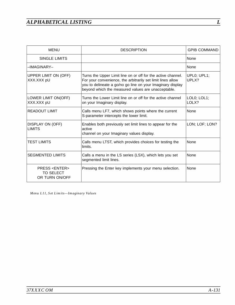
37XXXC OM A-131
ALPHABETICAL LISTING L
MENU DESCRIPTION GPIB COMMAND
SINGLE LIMITS None
–IMAGINARY– None
UPPER LIMIT ON (OFF)XXX.XXX pU
Turns the Upper Limit line on or off for the active channel.For your convenience, the arbitrarily set limit lines allowyou to delineate a go/no go line on your Imaginary displaybeyond which the measured values are unacceptable.
UPL0; UPL1;UPLX?
LOWER LIMIT ON(OFF)XXX.XXX pU
Turns the Lower Limit line on or off for the active channelon your Imaginary display.
LOL0; LOL1;LOLX?
READOUT LIMIT Calls menu LF7, which shows points where the currentS-parameter intercepts the lower limit.
None
DISPLAY ON (OFF)LIMITS
Enables both previously set limit lines to appear for theactivechannel on your Imaginary values display.
LON; LOF; LON?
TEST LIMITS Calls menu LTST, which provides choices for testing thelimits.
None
SEGMENTED LIMITS Calls a menu in the LS series (LSX), which lets you setsegmented limit lines.
None
PRESS <ENTER>TO SELECT
OR TURN ON/OFF
Pressing the Enter key implements your menu selection. None
Menu L11, Set Limits—Imaginary Values
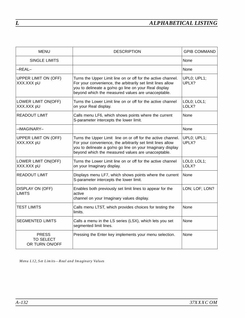
A-132 37XXXC OM
L ALPHABETICAL LISTING
MENU DESCRIPTION GPIB COMMAND
SINGLE LIMITS None
–REAL– None
UPPER LIMIT ON (OFF)XXX.XXX pU
Turns the Upper Limit line on or off for the active channel.For your convenience, the arbitrarily set limit lines allowyou to delineate a go/no go line on your Real displaybeyond which the measured values are unacceptable.
UPL0; UPL1;UPLX?
LOWER LIMIT ON(OFF)XXX.XXX pU
Turns the Lower Limit line on or off for the active channelon your Real display.
LOL0; LOL1;LOLX?
READOUT LIMIT Calls menu LF6, which shows points where the currentS-parameter intercepts the lower limit.
None
–IMAGINARY– None
UPPER LIMIT ON (OFF)XXX.XXX pU
Turns the Upper Limit line on or off for the active channel.For your convenience, the arbitrarily set limit lines allowyou to delineate a go/no go line on your Imaginary displaybeyond which the measured values are unacceptable.
UPL0; UPL1;UPLX?
LOWER LIMIT ON(OFF)XXX.XXX pU
Turns the Lower Limit line on or off for the active channelon your Imaginary display.
LOL0; LOL1;LOLX?
READOUT LIMIT Displays menu LF7, which shows points where the currentS-parameter intercepts the lower limit.
None
DISPLAY ON (OFF)LIMITS
Enables both previously set limit lines to appear for theactivechannel on your Imaginary values display.
LON; LOF; LON?
TEST LIMITS Calls menu LTST, which provides choices for testing thelimits.
None
SEGMENTED LIMITS Calls a menu in the LS series (LSX), which lets you setsegmented limit lines.
None
PRESSTO SELECT
OR TURN ON/OFF
Pressing the Enter key implements your menu selection. None
Menu L12, Set Limits—Real and Imaginary Values

37XXXC OM A-133
ALPHABETICAL LISTING L
MENU DESCRIPTION GPIB COMMAND
SINGLE LIMITS None
–SWR— None
UPPER LIMIT ON (OFF)XXX.XXX pU
Turns the Upper Limit line on or off for the active channel.For your convenience, the arbitrarily set limit lines allowyou to delineate a go/no go line on your SWR displaybeyond which the measured values are unacceptable.
UPL0; UPL1;UPLX?
LOWER LIMIT ON(OFF)XXX.XXX pU
Turns the Lower Limit line on or off for the active channelon your SWR display.
LOL0; LOL1;LOLX?
READOUT LIMIT Calls menu LF5, which shows points where the currentS-parameter intercepts the lower limit.
None
DISPLAY ON (OFF)LIMITS
Enables both previously set limit lines to appear for theactivechannel.
LON; LOF; LON?
TEST LIMITS Calls menu LTST, which provides choices for testing thelimits.
None
SEGMENTED LIMITS Calls a menu in the LS series (LSX), which lets you setsegmented limit lines.
None
PRESS <ENTER>TO SELECT
OR TURN ON/OFF
Pressing the Enter key implements your menu selection. None
Menu L13, Set Limits—SWR
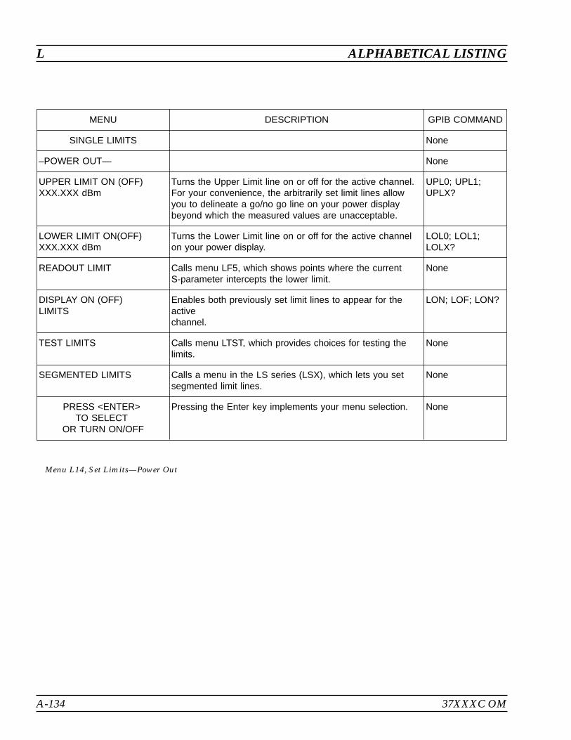
A-134 37XXXC OM
L ALPHABETICAL LISTING
MENU DESCRIPTION GPIB COMMAND
SINGLE LIMITS None
–POWER OUT— None
UPPER LIMIT ON (OFF)XXX.XXX dBm
Turns the Upper Limit line on or off for the active channel.For your convenience, the arbitrarily set limit lines allowyou to delineate a go/no go line on your power displaybeyond which the measured values are unacceptable.
UPL0; UPL1;UPLX?
LOWER LIMIT ON(OFF)XXX.XXX dBm
Turns the Lower Limit line on or off for the active channelon your power display.
LOL0; LOL1;LOLX?
READOUT LIMIT Calls menu LF5, which shows points where the currentS-parameter intercepts the lower limit.
None
DISPLAY ON (OFF)LIMITS
Enables both previously set limit lines to appear for theactivechannel.
LON; LOF; LON?
TEST LIMITS Calls menu LTST, which provides choices for testing thelimits.
None
SEGMENTED LIMITS Calls a menu in the LS series (LSX), which lets you setsegmented limit lines.
None
PRESS <ENTER>TO SELECT
OR TURN ON/OFF
Pressing the Enter key implements your menu selection. None
Menu L14, Set Limits—Power Out
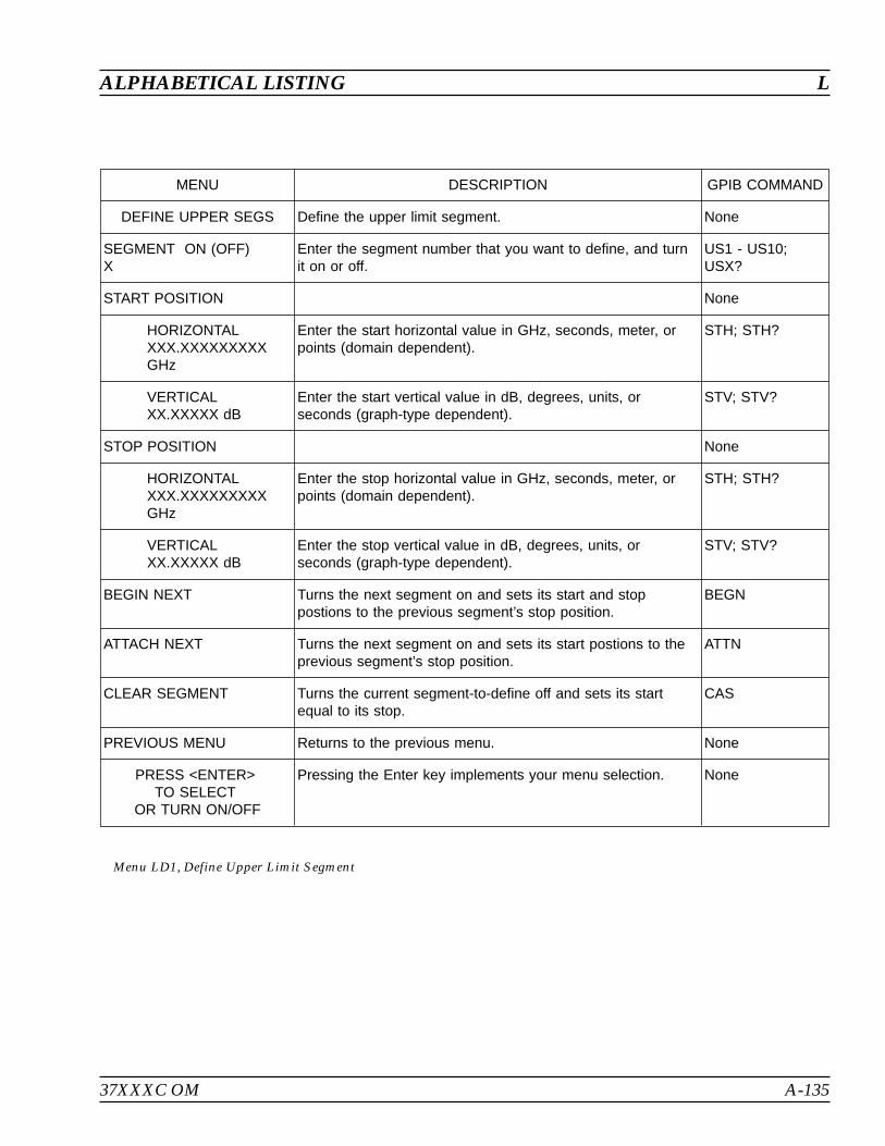
37XXXC OM A-135
ALPHABETICAL LISTING L
MENU DESCRIPTION GPIB COMMAND
DEFINE UPPER SEGS Define the upper limit segment. None
SEGMENT ON (OFF)X
Enter the segment number that you want to define, and turnit on or off.
US1 - US10;USX?
START POSITION None
HORIZONTALXXX.XXXXXXXXXGHz
Enter the start horizontal value in GHz, seconds, meter, orpoints (domain dependent).
STH; STH?
VERTICALXX.XXXXX dB
Enter the start vertical value in dB, degrees, units, orseconds (graph-type dependent).
STV; STV?
STOP POSITION None
HORIZONTALXXX.XXXXXXXXXGHz
Enter the stop horizontal value in GHz, seconds, meter, orpoints (domain dependent).
STH; STH?
VERTICALXX.XXXXX dB
Enter the stop vertical value in dB, degrees, units, orseconds (graph-type dependent).
STV; STV?
BEGIN NEXT Turns the next segment on and sets its start and stoppostions to the previous segment’s stop position.
BEGN
ATTACH NEXT Turns the next segment on and sets its start postions to theprevious segment’s stop position.
ATTN
CLEAR SEGMENT Turns the current segment-to-define off and sets its startequal to its stop.
CAS
PREVIOUS MENU Returns to the previous menu. None
PRESS <ENTER>TO SELECT
OR TURN ON/OFF
Pressing the Enter key implements your menu selection. None
Menu LD1, Define Upper Limit Segment
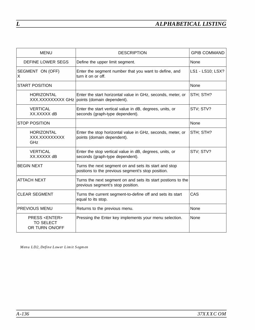
A-136 37XXXC OM
L ALPHABETICAL LISTING
MENU DESCRIPTION GPIB COMMAND
DEFINE LOWER SEGS Define the upper limit segment. None
SEGMENT ON (OFF)X
Enter the segment number that you want to define, andturn it on or off.
LS1 - LS10; LSX?
START POSITION None
HORIZONTALXXX.XXXXXXXXX GHz
Enter the start horizontal value in GHz, seconds, meter, orpoints (domain dependent).
STH; STH?
VERTICALXX.XXXXX dB
Enter the start vertical value in dB, degrees, units, orseconds (graph-type dependent).
STV; STV?
STOP POSITION None
HORIZONTALXXX.XXXXXXXXXGHz
Enter the stop horizontal value in GHz, seconds, meter, orpoints (domain dependent).
STH; STH?
VERTICALXX.XXXXX dB
Enter the stop vertical value in dB, degrees, units, orseconds (graph-type dependent).
STV; STV?
BEGIN NEXT Turns the next segment on and sets its start and stoppostions to the previous segment’s stop position.
ATTACH NEXT Turns the next segment on and sets its start postions to theprevious segment’s stop position.
CLEAR SEGMENT Turns the current segment-to-define off and sets its startequal to its stop.
CAS
PREVIOUS MENU Returns to the previous menu. None
PRESS <ENTER>TO SELECT
OR TURN ON/OFF
Pressing the Enter key implements your menu selection. None
Menu LD2, Define Lower Limit Segmen
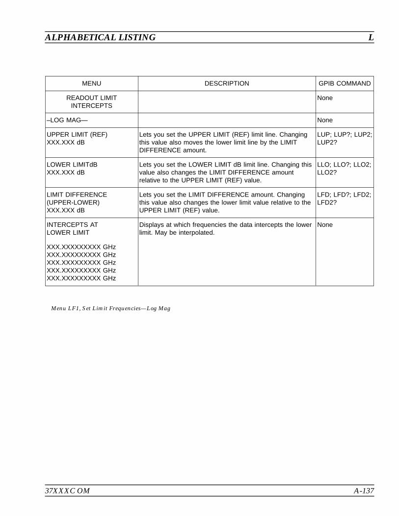
37XXXC OM A-137
ALPHABETICAL LISTING L
MENU DESCRIPTION GPIB COMMAND
READOUT LIMITINTERCEPTS
None
–LOG MAG— None
UPPER LIMIT (REF)XXX.XXX dB
Lets you set the UPPER LIMIT (REF) limit line. Changingthis value also moves the lower limit line by the LIMITDIFFERENCE amount.
LUP; LUP?; LUP2;LUP2?
LOWER LIMITdBXXX.XXX dB
Lets you set the LOWER LIMIT dB limit line. Changing thisvalue also changes the LIMIT DIFFERENCE amountrelative to the UPPER LIMIT (REF) value.
LLO; LLO?; LLO2;LLO2?
LIMIT DIFFERENCE(UPPER-LOWER)XXX.XXX dB
Lets you set the LIMIT DIFFERENCE amount. Changingthis value also changes the lower limit value relative to theUPPER LIMIT (REF) value.
LFD; LFD?; LFD2;LFD2?
INTERCEPTS ATLOWER LIMIT
Displays at which frequencies the data intercepts the lowerlimit. May be interpolated.
None
XXX.XXXXXXXXX GHzXXX.XXXXXXXXX GHzXXX.XXXXXXXXX GHzXXX.XXXXXXXXX GHzXXX.XXXXXXXXX GHz
Menu LF1, Set Limit Frequencies—Log Mag

A-138 37XXXC OM
L ALPHABETICAL LISTING
MENU DESCRIPTION GPIB COMMAND
READOUT LIMITINTERCEPTS
None
–PHASE— None
UPPER LIMIT (REF)XXX.XXX
Lets you set the UPPER LIMIT (REF) limit line. Changingthis value also moves the lower limit line by the LIMITDIFFERENCE amount.
LUP; LUP?; LUP2;LUP2?
LOWER LIMITdBXXX.XXX
Lets you set the LOWER LIMIT dB limit line. Changing thisvalue also changes the LIMIT DIFFERENCE amountrelative to the UPPER LIMIT (REF) value.
LLO; LLO?; LLO2;LLO2?
LIMIT DIFFERENCE(UPPER-LOWER)
Lets you set the LIMIT DIFFERENCE amount. Changingthis value also changes the lower limit value relative to theUPPER LIMIT (REF) value.
LFD; LFD?; LFD2;LFD2?
INTERCEPTS ATLOWER LIMIT
Displays at which frequencies the data intercepts the lowerlimit. May be interpolated.
None
XXX.XXXXXXXXX GHzXXX.XXXXXXXXX GHzXXX.XXXXXXXXX GHzXXX.XXXXXXXXX GHzXXX.XXXXXXXXX GHz
Menu LF2, Set Limit Frequencies—Phase

37XXXC OM A-139
ALPHABETICAL LISTING L
MENU DESCRIPTION GPIB COMMAND
READOUT LIMITINTERCEPTS
None
–GROUP DELAY— None
UPPER LIMIT (REF)XXX.XXX fs
Lets you set the UPPER LIMIT (REF) limit line. Changingthis value also moves the lower limit line by the LIMITDIFFERENCE amount.
LUP; LUP?; LUP2;LUP2?
LOWER LIMITXXX.XXX fs
Lets you set the LOWER LIMIT dB limit line. Changing thisvalue also changes the LIMIT DIFFERENCE amountrelative to the UPPER LIMIT (REF) value.
LLO; LLO?; LLO2;LLO2?
LIMIT DIFFERENCE(UPPER-LOWER)
Lets you set the LIMIT DIFFERENCE amount. Changingthis value also changes the lower limit value relative to theUPPER LIMIT (REF) value.
LFD; LFD?; LFD2;LFD2?
INTERCEPTS ATLOWER LIMIT
Displays at which frequencies the data intercepts the lowerlimit. May be interpolated.
None
XXX.XXXXXXXXX GHzXXX.XXXXXXXXX GHzXXX.XXXXXXXXX GHzXXX.XXXXXXXXX GHzXXX.XXXXXXXXX GHz
Menu LF3, Set Limit Frequencies—Group Delay

A-140 37XXXC OM
L ALPHABETICAL LISTING
MENU DESCRIPTION GPIB COMMAND
READOUT LIMITINTERCEPTS
None
–LINEAR MAG— None
UPPER LIMIT (REF)XXX.XXX pU
Lets you set the UPPER LIMIT (REF) limit line. Changingthis value also moves the lower limit line by the LIMITDIFFERENCE amount.
LUP; LUP?; LUP2;LUP2?
LOWER LIMITXXX.XXX pU
Lets you set the LOWER LIMIT dB limit line. Changing thisvalue also changes the LIMIT DIFFERENCE amountrelative to the UPPER LIMIT (REF) value.
LLO; LLO?; LLO2;LLO2?
LIMIT DIFFERENCE(UPPER-LOWER)XXX.XXX pU
Lets you set the LIMIT DIFFERENCE amount. Changingthis value also changes the lower limit value relative to theUPPER LIMIT (REF) value.
LFD; LFD?; LFD2;LFD2?
INTERCEPTS ATLOWER LIMIT
Displays at which frequencies the data intercepts the lowerlimit. May be interpolated.
None
XXX.XXXXXXXXX GHzXXX.XXXXXXXXX GHzXXX.XXXXXXXXX GHzXXX.XXXXXXXXX GHzXXX.XXXXXXXXX GHz
Menu LF4, Set Limit Frequencies—Linear Mag

37XXXC OM A-141
ALPHABETICAL LISTING L
MENU DESCRIPTION GPIB COMMAND
SET LIMITFREQUENCIES
None
–SWR— None
UPPER LIMIT (REF)XXX.XXX pU
Lets you set the UPPER LIMIT (REF) limit line. Changingthis value also moves the lower limit line by the LIMITDIFFERENCE amount.
LUP; LUP?; LUP2;LUP2?
LOWER LIMITXXX.XXX pU
Lets you set the LOWER LIMIT dB limit line. Changing thisvalue also changes the LIMIT DIFFERENCE amountrelative to the UPPER LIMIT (REF) value.
LLO; LLO?; LLO2;LLO2?
LIMIT DIFFERENCE(UPPER-LOWER)XXX.XXX pU
Lets you set the LIMIT DIFFERENCE amount. Changingthis value also changes the lower limit value relative to theUPPER LIMIT (REF) value.
LFD; LFD?; LFD2;LFD2?
INTERCEPTS ATLOWER LIMIT
Displays at which frequencies the data intercepts the lowerlimit. May be interpolated.
None
XXX.XXXXXXXXX GHzXXX.XXXXXXXXX GHzXXX.XXXXXXXXX GHzXXX.XXXXXXXXX GHzXXX.XXXXXXXXX GHz
Menu LF5, Set Limit Frequencies—SWR

A-142 37XXXC OM
L ALPHABETICAL LISTING
MENU DESCRIPTION GPIB COMMAND
SET LIMITFREQUENCIES
None
–REAL— None
UPPER LIMIT (REF)XXX.XXX pU
Lets you set the UPPER LIMIT (REF) limit line. Changingthis value also moves the lower limit line by the LIMITDIFFERENCE amount.
LUP; LUP?; LUP2;LUP2?
LOWER LIMITXXX.XXX pU
Lets you set the LOWER LIMIT dB limit line. Changing thisvalue also changes the LIMIT DIFFERENCE amountrelative to the UPPER LIMIT (REF) value.
LLO; LLO?; LLO2;LLO2?
LIMIT DIFFERENCE(UPPER-LOWER)
Lets you set the LIMIT DIFFERENCE amount. Changingthis value also changes the lower limit value relative to theUPPER LIMIT (REF) value.
LFD; LFD?; LFD2;LFD2?
INTERCEPTS ATLOWER LIMIT
Displays at which frequencies the data intercepts the lowerlimit. May be interpolated.
None
XXX.XXXXXXXXX GHzXXX.XXXXXXXXX GHzXXX.XXXXXXXXX GHzXXX.XXXXXXXXX GHzXXX.XXXXXXXXX GHz
Menu LF6, Set Limit Frequencies—Real

37XXXC OM A-143
ALPHABETICAL LISTING L
MENU DESCRIPTION GPIB COMMAND
SET LIMITFREQUENCIES
None
–IMAGINARY— None
UPPER LIMIT (REF)XXX.XXX pU
Lets you set the UPPER LIMIT (REF) limit line. Changingthis value also moves the lower limit line by the LIMITDIFFERENCE amount.
LUP; LUP?; LUP2;LUP2?
LOWER LIMITXXX.XXX pU
Lets you set the LOWER LIMIT dB limit line. Changing thisvalue also changes the LIMIT DIFFERENCE amountrelative to the UPPER LIMIT (REF) value.
LLO; LLO?; LLO2;LLO2?
LIMIT DIFFERENCE(UPPER-LOWER)
Lets you set the LIMIT DIFFERENCE amount. Changingthis value also changes the lower limit value relative to theUPPER LIMIT (REF) value.
LFD; LFD?; LFD2;LFD2?
INTERCEPTS ATLOWER LIMIT
Displays at which frequencies the data intercepts the lowerlimit. May be interpolated.
None
XXX.XXXXXXXXX GHzXXX.XXXXXXXXX GHzXXX.XXXXXXXXX GHzXXX.XXXXXXXXX GHzXXX.XXXXXXXXX GHz
Menu LF7, Set Limit Frequencies—Imaginary
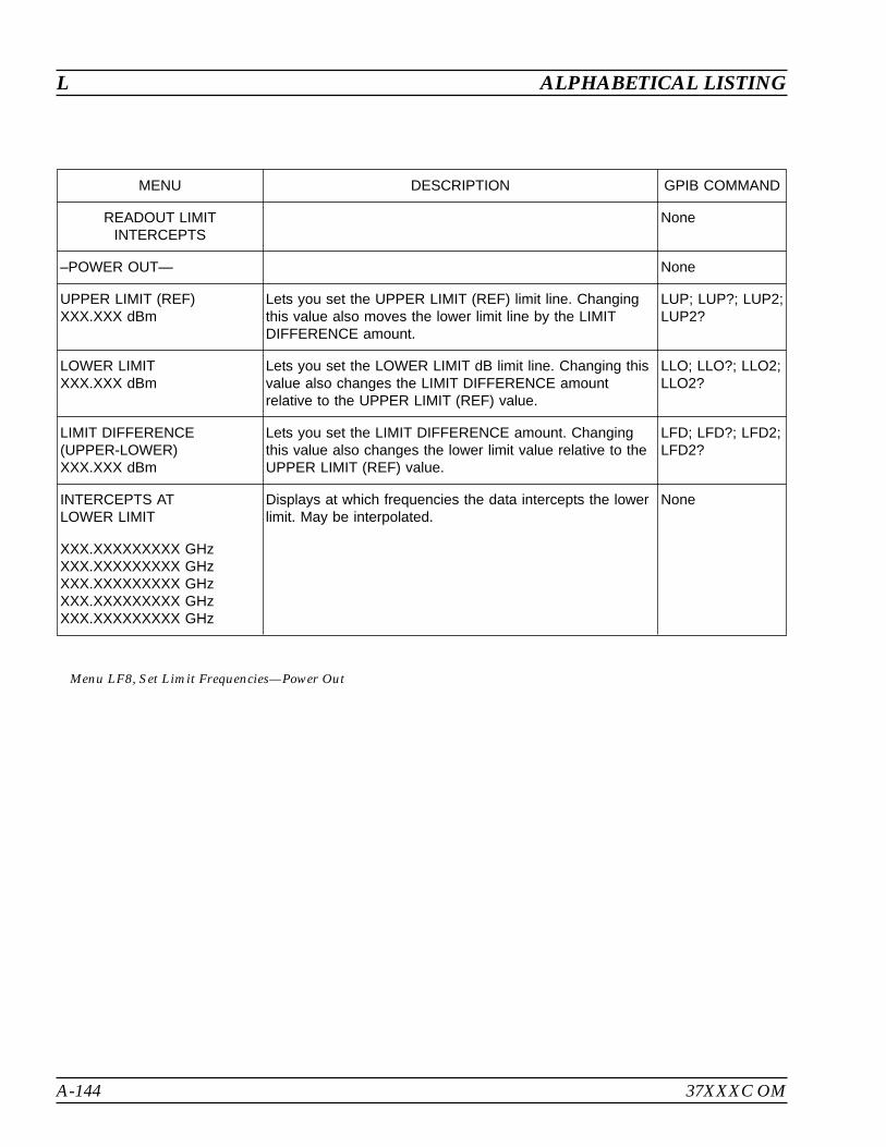
A-144 37XXXC OM
L ALPHABETICAL LISTING
MENU DESCRIPTION GPIB COMMAND
READOUT LIMITINTERCEPTS
None
–POWER OUT— None
UPPER LIMIT (REF)XXX.XXX dBm
Lets you set the UPPER LIMIT (REF) limit line. Changingthis value also moves the lower limit line by the LIMITDIFFERENCE amount.
LUP; LUP?; LUP2;LUP2?
LOWER LIMITXXX.XXX dBm
Lets you set the LOWER LIMIT dB limit line. Changing thisvalue also changes the LIMIT DIFFERENCE amountrelative to the UPPER LIMIT (REF) value.
LLO; LLO?; LLO2;LLO2?
LIMIT DIFFERENCE(UPPER-LOWER)XXX.XXX dBm
Lets you set the LIMIT DIFFERENCE amount. Changingthis value also changes the lower limit value relative to theUPPER LIMIT (REF) value.
LFD; LFD?; LFD2;LFD2?
INTERCEPTS ATLOWER LIMIT
Displays at which frequencies the data intercepts the lowerlimit. May be interpolated.
None
XXX.XXXXXXXXX GHzXXX.XXXXXXXXX GHzXXX.XXXXXXXXX GHzXXX.XXXXXXXXX GHzXXX.XXXXXXXXX GHz
Menu LF8, Set Limit Frequencies—Power Out
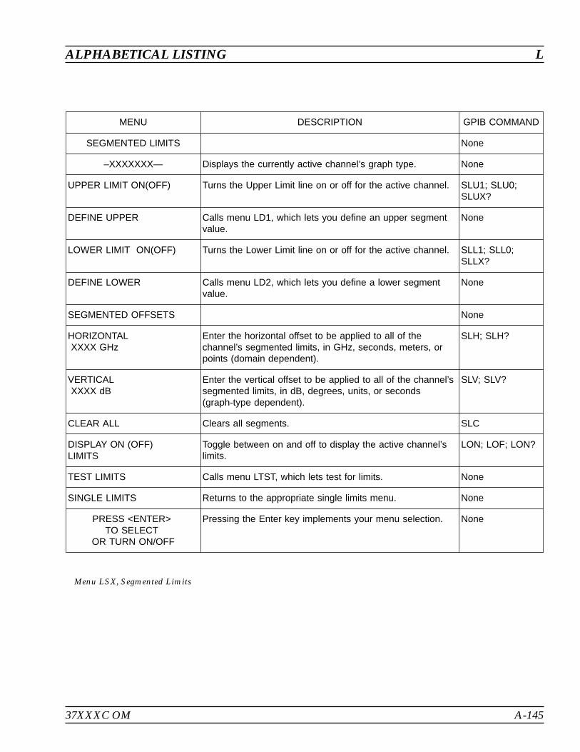
37XXXC OM A-145
ALPHABETICAL LISTING L
MENU DESCRIPTION GPIB COMMAND
SEGMENTED LIMITS None
–XXXXXXX— Displays the currently active channel’s graph type. None
UPPER LIMIT ON(OFF) Turns the Upper Limit line on or off for the active channel. SLU1; SLU0;SLUX?
DEFINE UPPER Calls menu LD1, which lets you define an upper segmentvalue.
None
LOWER LIMIT ON(OFF) Turns the Lower Limit line on or off for the active channel. SLL1; SLL0;SLLX?
DEFINE LOWER Calls menu LD2, which lets you define a lower segmentvalue.
None
SEGMENTED OFFSETS None
HORIZONTALXXXX GHz
Enter the horizontal offset to be applied to all of thechannel’s segmented limits, in GHz, seconds, meters, orpoints (domain dependent).
SLH; SLH?
VERTICALXXXX dB
Enter the vertical offset to be applied to all of the channel’ssegmented limits, in dB, degrees, units, or seconds(graph-type dependent).
SLV; SLV?
CLEAR ALL Clears all segments. SLC
DISPLAY ON (OFF)LIMITS
Toggle between on and off to display the active channel’slimits.
LON; LOF; LON?
TEST LIMITS Calls menu LTST, which lets test for limits. None
SINGLE LIMITS Returns to the appropriate single limits menu. None
PRESS <ENTER>TO SELECT
OR TURN ON/OFF
Pressing the Enter key implements your menu selection. None
Menu LSX, Segmented Limits
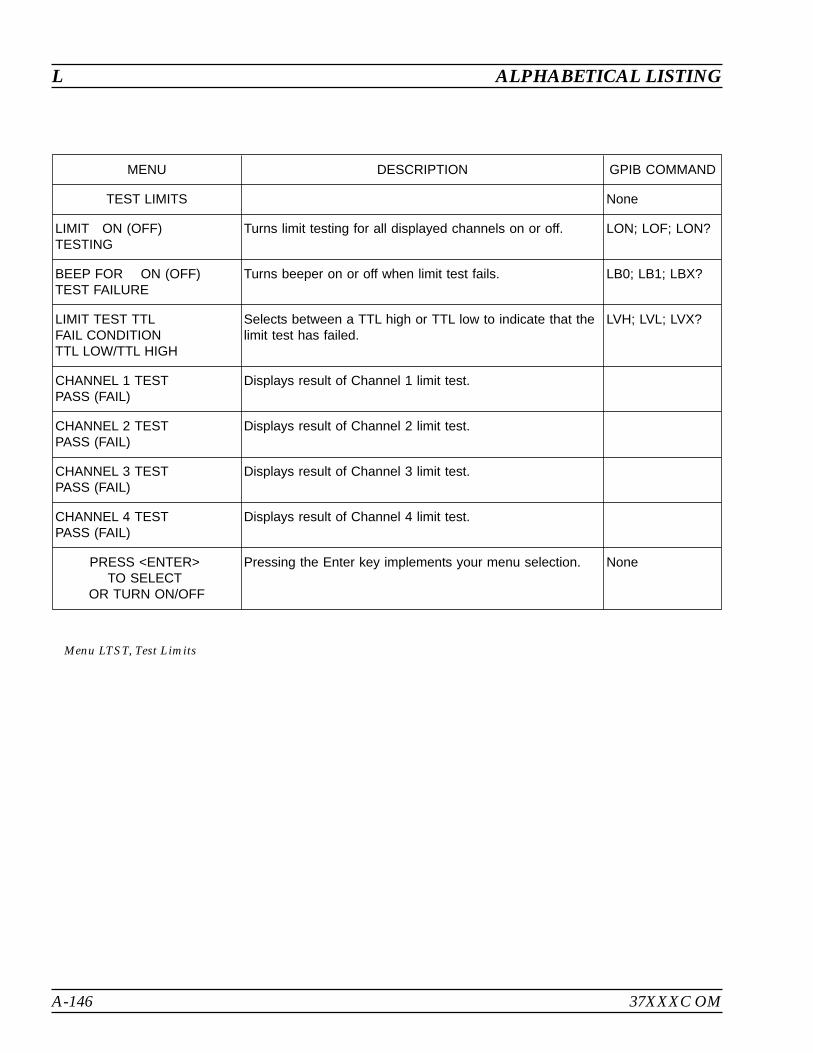
A-146 37XXXC OM
L ALPHABETICAL LISTING
MENU DESCRIPTION GPIB COMMAND
TEST LIMITS None
LIMIT ON (OFF)TESTING
Turns limit testing for all displayed channels on or off. LON; LOF; LON?
BEEP FOR ON (OFF)TEST FAILURE
Turns beeper on or off when limit test fails. LB0; LB1; LBX?
LIMIT TEST TTLFAIL CONDITIONTTL LOW/TTL HIGH
Selects between a TTL high or TTL low to indicate that thelimit test has failed.
LVH; LVL; LVX?
CHANNEL 1 TESTPASS (FAIL)
Displays result of Channel 1 limit test.
CHANNEL 2 TESTPASS (FAIL)
Displays result of Channel 2 limit test.
CHANNEL 3 TESTPASS (FAIL)
Displays result of Channel 3 limit test.
CHANNEL 4 TESTPASS (FAIL)
Displays result of Channel 4 limit test.
PRESS <ENTER>TO SELECT
OR TURN ON/OFF
Pressing the Enter key implements your menu selection. None
Menu LTST, Test Limits
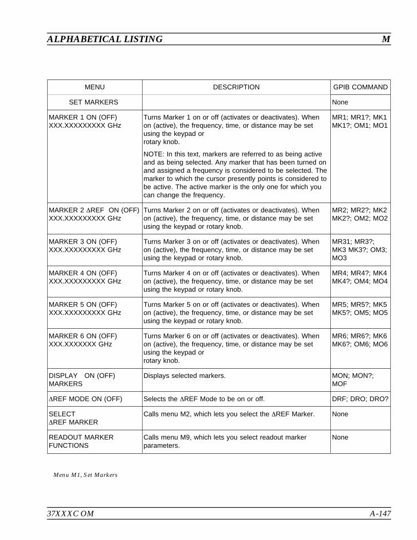
37XXXC OM A-147
ALPHABETICAL LISTING M
MENU DESCRIPTION GPIB COMMAND
SET MARKERS None
MARKER 1 ON (OFF)XXX.XXXXXXXXX GHz
Turns Marker 1 on or off (activates or deactivates). Whenon (active), the frequency, time, or distance may be setusing the keypad orrotary knob.
NOTE: In this text, markers are referred to as being activeand as being selected. Any marker that has been turned onand assigned a frequency is considered to be selected. Themarker to which the cursor presently points is considered tobe active. The active marker is the only one for which youcan change the frequency.
MR1; MR1?; MK1MK1?; OM1; MO1
MARKER 2 REF ON (OFF)XXX.XXXXXXXXX GHz
Turns Marker 2 on or off (activates or deactivates). Whenon (active), the frequency, time, or distance may be setusing the keypad or rotary knob.
MR2; MR2?; MK2MK2?; OM2; MO2
MARKER 3 ON (OFF)XXX.XXXXXXXXX GHz
Turns Marker 3 on or off (activates or deactivates). Whenon (active), the frequency, time, or distance may be setusing the keypad or rotary knob.
MR31; MR3?;MK3 MK3?; OM3;MO3
MARKER 4 ON (OFF)XXX.XXXXXXXXX GHz
Turns Marker 4 on or off (activates or deactivates). Whenon (active), the frequency, time, or distance may be setusing the keypad or rotary knob.
MR4; MR4?; MK4MK4?; OM4; MO4
MARKER 5 ON (OFF)XXX.XXXXXXXXX GHz
Turns Marker 5 on or off (activates or deactivates). Whenon (active), the frequency, time, or distance may be setusing the keypad or rotary knob.
MR5; MR5?; MK5MK5?; OM5; MO5
MARKER 6 ON (OFF)XXX.XXXXXXX GHz
Turns Marker 6 on or off (activates or deactivates). Whenon (active), the frequency, time, or distance may be setusing the keypad orrotary knob.
MR6; MR6?; MK6MK6?; OM6; MO6
DISPLAY ON (OFF)MARKERS
Displays selected markers. MON; MON?;MOF
REF MODE ON (OFF) Selects the REF Mode to be on or off. DRF; DRO; DRO?
SELECTREF MARKER
Calls menu M2, which lets you select the REF Marker. None
READOUT MARKERFUNCTIONS
Calls menu M9, which lets you select readout markerparameters.
None
Menu M1, Set Markers
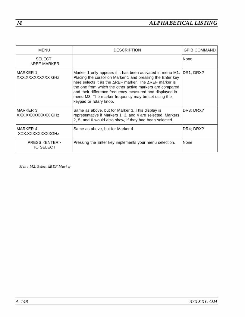
A-148 37XXXC OM
M ALPHABETICAL LISTING
MENU DESCRIPTION GPIB COMMAND
SELECTREF MARKER
None
MARKER 1XXX.XXXXXXXXX GHz
Marker 1 only appears if it has been activated in menu M1.Placing the cursor on Marker 1 and pressing the Enter keyhere selects it as the REF marker. The REF marker isthe one from which the other active markers are comparedand their difference frequency measured and displayed inmenu M3. The marker frequency may be set using thekeypad or rotary knob.
DR1; DRX?
MARKER 3XXX.XXXXXXXXX GHz
Same as above, but for Marker 3. This display isrepresentative if Markers 1, 3, and 4 are selected. Markers2, 5, and 6 would also show, if they had been selected.
DR3; DRX?
MARKER 4XXX.XXXXXXXXXGHz
Same as above, but for Marker 4 DR4; DRX?
PRESS <ENTER>TO SELECT
Pressing the Enter key implements your menu selection. None
Menu M2, Select REF Marker

37XXXC OM A-149
ALPHABETICAL LISTING M
MENU DESCRIPTION GPIB COMMAND
SELECTREADOUT MARKER
None
MARKER 1XXX.XXXXXXXXX GHz
Displays the frequency and S-Parameter value(s) ofMarker 1 on all displayed graphs and Smith Charts. Thefrequency of Marker 1 also displays here. If Marker 1was activated in menu M2 as the REF marker, REFappears as shown for Marker M5 below.
DR1; DRX?
MARKER 2XXX.XXXXXXXXX GHz
Same as above, but for Marker 2. DR2; DRX?
MARKER 5XXX.XXXXXXXXX GHz
Same as above, but for Marker 5 This display isrepresentative if Markers 1, 2, and 5 are selected.Markers 3, 4, and 6 would also show, if they had beenselected.
DR5; DRX?
REF MODE IS ON (OFF) Indicates the status of the REF mode. DRO; DRO?
PRESS <ENTER>TO SELECT
Pressing the Enter key implements your menu selection. None
Menu M3, Select Readout Marker

A-150 37XXXC OM
M ALPHABETICAL LISTING
MENU DESCRIPTION GPIB COMMAND
C H 1 — S 1 1, USER Selects channel for readout None
+XXX.XXXX mm REF+XXX.XXX dB OFFSET+XXX.XX OFFSET
The constant offset for the channel is displayed. None
MARKER XXXX.XXXXXXXXX GHzXX.XXX dBXXX.XXX
The selected marker—that is, the one to which thecursor points in menu M1—and its frequency, time, ordistance display here. This could be any one of the sixavailable markers: Marker 1 through Marker 6.
MR1; MR1? MK1;MK1? OM1
MARKER TO MAX Causes the active marker to go to the frequency withthe greatestS-Parameter value on the active channel.
MMX
MARKER TO MIN Causes the selected marker to go to the frequencywith the smallestS-Parameter value on the active channel.
MMN
2 XXX.XXXXXXXXX GHzXX.XXX dBXXX.XXX
Displays the frequency, magnitude, and phase of theactiveS-Parameter at marker 2, if the marker is enabled.
MR2; MR2? MK2;MK2? OM2
3 XXX.XXXXXXXXX GHzXX.XXX dBXXX.XXX
Displays the frequency, magnitude, and phase of theactiveS-Parameter at marker 3, if the marker is enabled.
MR3; MR3? MK3;MK3? OM3
4 XXX.XXXXXXXXX GHzXX.XXX dBXXX.XXX
Displays the frequency, magnitude, and phase of theactiveS-Parameter at marker 4, if the marker is enabled.
MR4; MR4? MK4;MK4? OM4
5 XXX.XXXXXXXXX GHzXX.XXX dBXXX.XXX
Displays the frequency, magnitude, and phase of theactiveS-Parameter at marker 5, if the marker is enabled.
MR5; MR5? MK5;MK5? OM5
6 XXX.XXXXXXXXX GHzXX.XXX dBXXX.XXX
Displays the frequency, magnitude, and phase of theactiveS-Parameter at marker 6, if the marker is enabled.
MR6; MR6? MK6;MK6? OM6
MARKER READOUTFUNCTIONS
Calls menu M9, which lets you select readout markerparameters.
None
Menu M4, Readout Marker
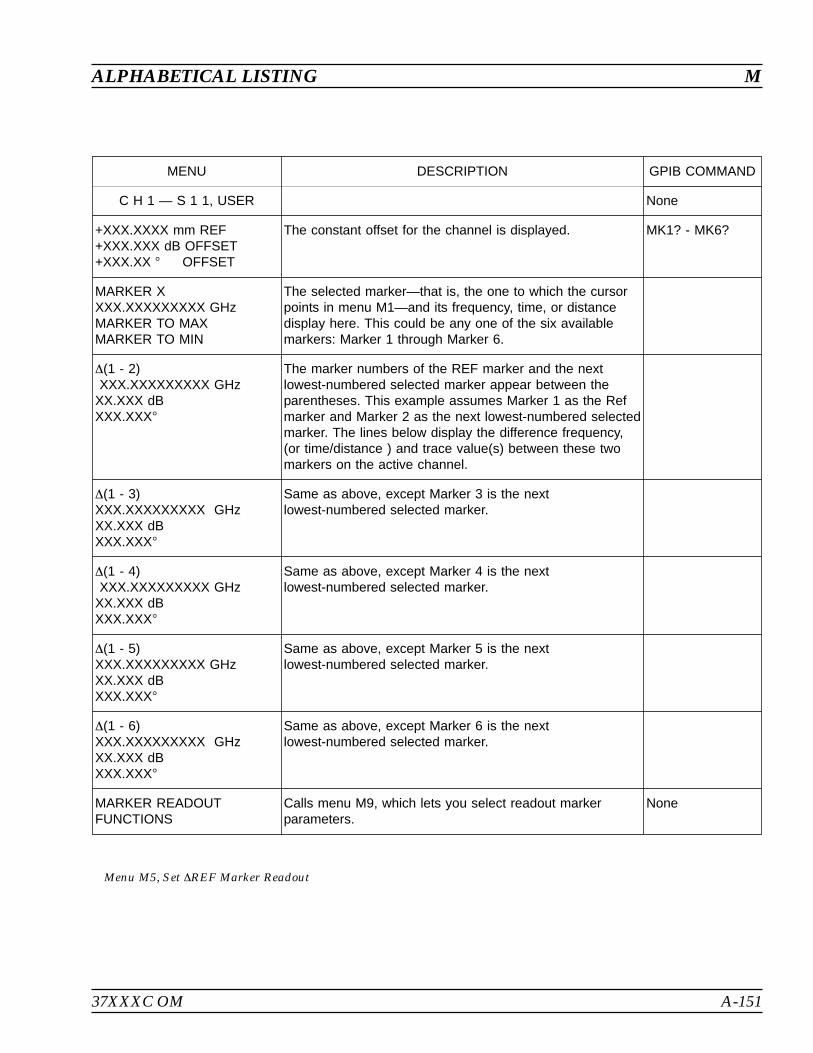
37XXXC OM A-151
ALPHABETICAL LISTING M
MENU DESCRIPTION GPIB COMMAND
C H 1 — S 1 1, USER None
+XXX.XXXX mm REF+XXX.XXX dB OFFSET+XXX.XX OFFSET
The constant offset for the channel is displayed. MK1? - MK6?
MARKER XXXX.XXXXXXXXX GHzMARKER TO MAXMARKER TO MIN
The selected marker—that is, the one to which the cursorpoints in menu M1—and its frequency, time, or distancedisplay here. This could be any one of the six availablemarkers: Marker 1 through Marker 6.
(1 - 2)XXX.XXXXXXXXX GHz
XX.XXX dBXXX.XXX
The marker numbers of the REF marker and the nextlowest-numbered selected marker appear between theparentheses. This example assumes Marker 1 as the Refmarker and Marker 2 as the next lowest-numbered selectedmarker. The lines below display the difference frequency,(or time/distance ) and trace value(s) between these twomarkers on the active channel.
(1 - 3)XXX.XXXXXXXXX GHzXX.XXX dBXXX.XXX
Same as above, except Marker 3 is the nextlowest-numbered selected marker.
(1 - 4)XXX.XXXXXXXXX GHz
XX.XXX dBXXX.XXX
Same as above, except Marker 4 is the nextlowest-numbered selected marker.
(1 - 5)XXX.XXXXXXXXX GHzXX.XXX dBXXX.XXX
Same as above, except Marker 5 is the nextlowest-numbered selected marker.
(1 - 6)XXX.XXXXXXXXX GHzXX.XXX dBXXX.XXX
Same as above, except Marker 6 is the nextlowest-numbered selected marker.
MARKER READOUTFUNCTIONS
Calls menu M9, which lets you select readout markerparameters.
None
Menu M5, Set REF Marker Readout

A-152 37XXXC OM
M ALPHABETICAL LISTING
MENU DESCRIPTION GPIB COMMAND
MARKER XALL DISPLAYED
CHANNELS
Displays the active marker number. For each channelbeing displayed, the channel, S-Parameter, frequency,time, distance or point number, and the currentreadout value for the marker is shown (below). Nomarker information is provided for channels that arernot displayed .
None
CH 1 — S11XX.XXXXXXXXX GHz–XXX.XXX dB–XXX.XX
Displays the measured value for the active marker onall channels currently being displayed. You can set themarker on the active channel in this menu. The activechannel is displayed in GREEN; when not active it isdisplayed in BLUE.
OAM1
CH 2 — S21 See above. OAM2
CH 3 — S12XX.XXXXXXXXX GHz–XXX.XXX dB–XXX.XX
See above. OAM3
CH 4 — S22 See above. OAM4
MARKER TO MAX Causes the active marker to go to the frequency withthe greatestS-Parameter value on the active channel.
MMX
MARKER TO MIN Causes the selected marker to go to the frequencywith the smallestS-Parameter value on the active channel.
MMN
MARKER READOUTFUNCTIONS
Calls menu M9, which lets you select readout markerparameters.
None
PRESS <ENTER>TO SELECT
Pressing the Enter key implements menu selection. None
Menu M6, Marker X All Displayed Channels
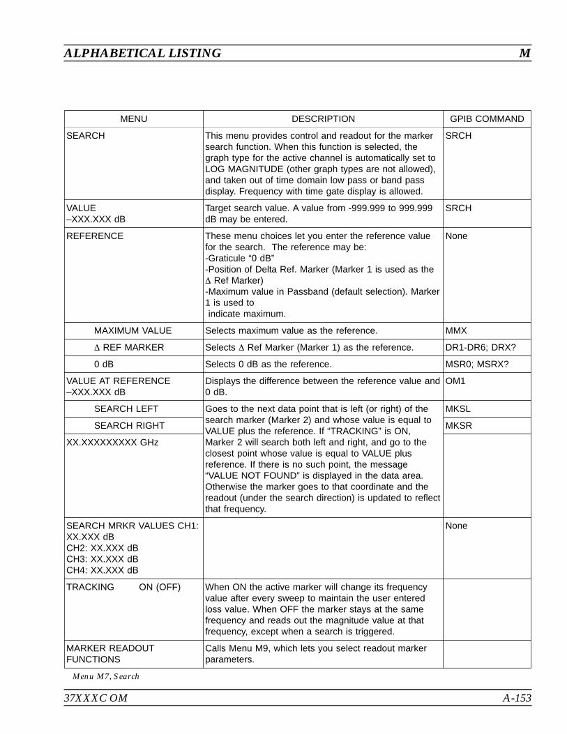
37XXXC OM A-153
ALPHABETICAL LISTING M
MENU DESCRIPTION GPIB COMMAND
SEARCH This menu provides control and readout for the markersearch function. When this function is selected, thegraph type for the active channel is automatically set toLOG MAGNITUDE (other graph types are not allowed),and taken out of time domain low pass or band passdisplay. Frequency with time gate display is allowed.
SRCH
VALUE–XXX.XXX dB
Target search value. A value from -999.999 to 999.999dB may be entered.
SRCH
REFERENCE These menu choices let you enter the reference valuefor the search. The reference may be:-Graticule “0 dB”-Position of Delta Ref. Marker (Marker 1 is used as the Ref Marker)-Maximum value in Passband (default selection). Marker1 is used toindicate maximum.
None
MAXIMUM VALUE Selects maximum value as the reference. MMX
REF MARKER Selects Ref Marker (Marker 1) as the reference. DR1-DR6; DRX?
0 dB Selects 0 dB as the reference. MSR0; MSRX?
VALUE AT REFERENCE–XXX.XXX dB
Displays the difference between the reference value and0 dB.
OM1
SEARCH LEFT Goes to the next data point that is left (or right) of thesearch marker (Marker 2) and whose value is equal toVALUE plus the reference. If “TRACKING” is ON,Marker 2 will search both left and right, and go to theclosest point whose value is equal to VALUE plusreference. If there is no such point, the message“VALUE NOT FOUND” is displayed in the data area.Otherwise the marker goes to that coordinate and thereadout (under the search direction) is updated to reflectthat frequency.
MKSL
SEARCH RIGHT MKSR
XX.XXXXXXXXX GHz
SEARCH MRKR VALUES CH1:XX.XXX dBCH2: XX.XXX dBCH3: XX.XXX dBCH4: XX.XXX dB
None
TRACKING ON (OFF) When ON the active marker will change its frequencyvalue after every sweep to maintain the user enteredloss value. When OFF the marker stays at the samefrequency and reads out the magnitude value at thatfrequency, except when a search is triggered.
MARKER READOUTFUNCTIONS
Calls Menu M9, which lets you select readout markerparameters.
Menu M7, Search
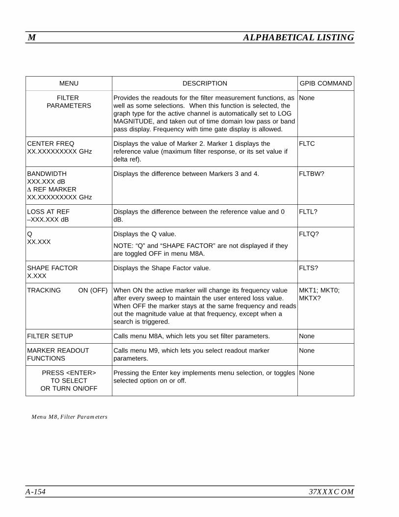
A-154 37XXXC OM
M ALPHABETICAL LISTING
MENU DESCRIPTION GPIB COMMAND
FILTERPARAMETERS
Provides the readouts for the filter measurement functions, aswell as some selections. When this function is selected, thegraph type for the active channel is automatically set to LOGMAGNITUDE, and taken out of time domain low pass or bandpass display. Frequency with time gate display is allowed.
None
CENTER FREQXX.XXXXXXXXX GHz
Displays the value of Marker 2. Marker 1 displays thereference value (maximum filter response, or its set value ifdelta ref).
FLTC
BANDWIDTHXXX.XXX dB REF MARKERXX.XXXXXXXXX GHz
Displays the difference between Markers 3 and 4. FLTBW?
LOSS AT REF–XXX.XXX dB
Displays the difference between the reference value and 0dB.
FLTL?
QXX.XXX
Displays the Q value.
NOTE: “Q” and “SHAPE FACTOR” are not displayed if theyare toggled OFF in menu M8A.
FLTQ?
SHAPE FACTORX.XXX
Displays the Shape Factor value. FLTS?
TRACKING ON (OFF) When ON the active marker will change its frequency valueafter every sweep to maintain the user entered loss value.When OFF the marker stays at the same frequency and readsout the magnitude value at that frequency, except when asearch is triggered.
MKT1; MKT0;MKTX?
FILTER SETUP Calls menu M8A, which lets you set filter parameters. None
MARKER READOUTFUNCTIONS
Calls menu M9, which lets you select readout markerparameters.
None
PRESS <ENTER>TO SELECT
OR TURN ON/OFF
Pressing the Enter key implements menu selection, or togglesselected option on or off.
None
Menu M8, Filter Parameters
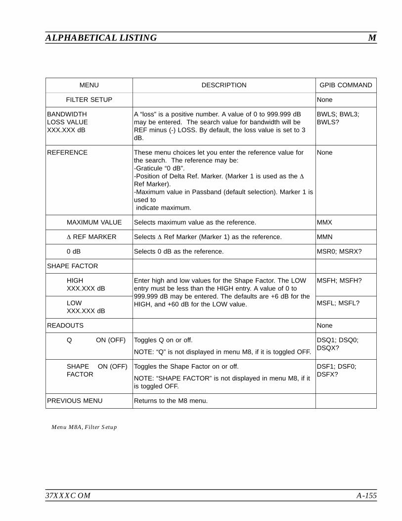
37XXXC OM A-155
ALPHABETICAL LISTING M
MENU DESCRIPTION GPIB COMMAND
FILTER SETUP None
BANDWIDTHLOSS VALUEXXX.XXX dB
A “loss” is a positive number. A value of 0 to 999.999 dBmay be entered. The search value for bandwidth will beREF minus (-) LOSS. By default, the loss value is set to 3dB.
BWLS; BWL3;BWLS?
REFERENCE These menu choices let you enter the reference value forthe search. The reference may be:-Graticule “0 dB”.-Position of Delta Ref. Marker. (Marker 1 is used as the
Ref Marker).-Maximum value in Passband (default selection). Marker 1 isused toindicate maximum.
None
MAXIMUM VALUE Selects maximum value as the reference. MMX
REF MARKER Selects Ref Marker (Marker 1) as the reference. MMN
0 dB Selects 0 dB as the reference. MSR0; MSRX?
SHAPE FACTOR
HIGHXXX.XXX dB
Enter high and low values for the Shape Factor. The LOWentry must be less than the HIGH entry. A value of 0 to999.999 dB may be entered. The defaults are +6 dB for theHIGH, and +60 dB for the LOW value.
MSFH; MSFH?
LOWXXX.XXX dB
MSFL; MSFL?
READOUTS None
Q ON (OFF) Toggles Q on or off.
NOTE: “Q” is not displayed in menu M8, if it is toggled OFF.
DSQ1; DSQ0;DSQX?
SHAPE ON (OFF)FACTOR
Toggles the Shape Factor on or off.
NOTE: “SHAPE FACTOR” is not displayed in menu M8, if itis toggled OFF.
DSF1; DSF0;DSFX?
PREVIOUS MENU Returns to the M8 menu.
Menu M8A, Filter Setup
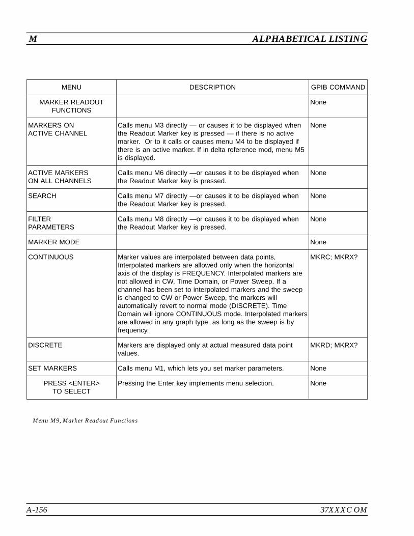
A-156 37XXXC OM
M ALPHABETICAL LISTING
MENU DESCRIPTION GPIB COMMAND
MARKER READOUTFUNCTIONS
None
MARKERS ONACTIVE CHANNEL
Calls menu M3 directly — or causes it to be displayed whenthe Readout Marker key is pressed — if there is no activemarker. Or to it calls or causes menu M4 to be displayed ifthere is an active marker. If in delta reference mod, menu M5is displayed.
None
ACTIVE MARKERSON ALL CHANNELS
Calls menu M6 directly —or causes it to be displayed whenthe Readout Marker key is pressed.
None
SEARCH Calls menu M7 directly —or causes it to be displayed whenthe Readout Marker key is pressed.
None
FILTERPARAMETERS
Calls menu M8 directly —or causes it to be displayed whenthe Readout Marker key is pressed.
None
MARKER MODE None
CONTINUOUS Marker values are interpolated between data points,Interpolated markers are allowed only when the horizontalaxis of the display is FREQUENCY. Interpolated markers arenot allowed in CW, Time Domain, or Power Sweep. If achannel has been set to interpolated markers and the sweepis changed to CW or Power Sweep, the markers willautomatically revert to normal mode (DISCRETE). TimeDomain will ignore CONTINUOUS mode. Interpolated markersare allowed in any graph type, as long as the sweep is byfrequency.
MKRC; MKRX?
DISCRETE Markers are displayed only at actual measured data pointvalues.
MKRD; MKRX?
SET MARKERS Calls menu M1, which lets you set marker parameters. None
PRESS <ENTER>TO SELECT
Pressing the Enter key implements menu selection. None
Menu M9, Marker Readout Functions
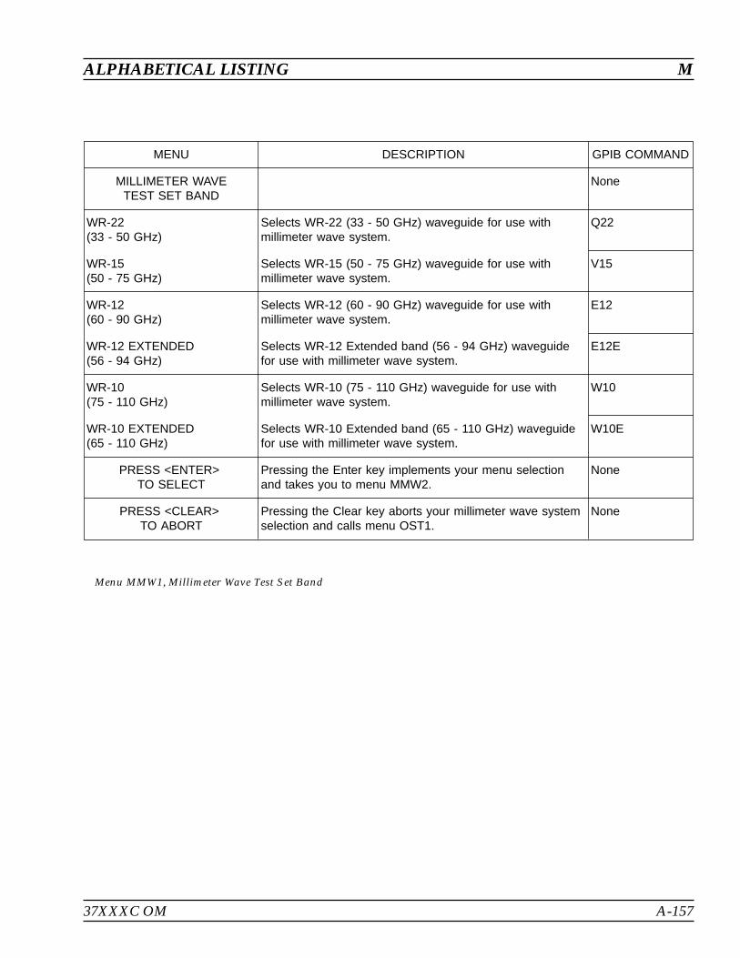
37XXXC OM A-157
ALPHABETICAL LISTING M
MENU DESCRIPTION GPIB COMMAND
MILLIMETER WAVETEST SET BAND
None
WR-22(33 - 50 GHz)
Selects WR-22 (33 - 50 GHz) waveguide for use withmillimeter wave system.
Q22
WR-15(50 - 75 GHz)
Selects WR-15 (50 - 75 GHz) waveguide for use withmillimeter wave system.
V15
WR-12(60 - 90 GHz)
Selects WR-12 (60 - 90 GHz) waveguide for use withmillimeter wave system.
E12
WR-12 EXTENDED(56 - 94 GHz)
Selects WR-12 Extended band (56 - 94 GHz) waveguidefor use with millimeter wave system.
E12E
WR-10(75 - 110 GHz)
Selects WR-10 (75 - 110 GHz) waveguide for use withmillimeter wave system.
W10
WR-10 EXTENDED(65 - 110 GHz)
Selects WR-10 Extended band (65 - 110 GHz) waveguidefor use with millimeter wave system.
W10E
PRESS <ENTER>TO SELECT
Pressing the Enter key implements your menu selectionand takes you to menu MMW2.
None
PRESS <CLEAR>TO ABORT
Pressing the Clear key aborts your millimeter wave systemselection and calls menu OST1.
None
Menu MMW1, Millimeter Wave Test Set Band
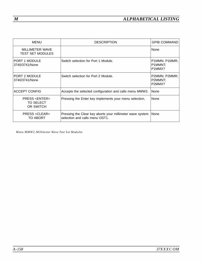
A-158 37XXXC OM
M ALPHABETICAL LISTING
MENU DESCRIPTION GPIB COMMAND
MILLIMETER WAVETEST SET MODULES
None
PORT 1 MODULE3740/3741/None
Switch selection for Port 1 Module. P1MMN; P1MMR;P1MMNT;P1MMX?
PORT 2 MODULE3740/3741/None
Switch selection for Port 2 Module. P2MMN; P2MMR;P2MMNT;P2MMX?
ACCEPT CONFIG Accepts the selected configuration and calls menu MMW3. None
PRESS <ENTER>TO SELECTOR SWITCH
Pressing the Enter key implements your menu selection, None
PRESS <CLEAR>TO ABORT
Pressing the Clear key aborts your millimeter wave systemselection and calls menu OST1.
None
Menu MMW2, Millimeter Wave Test Set Modules
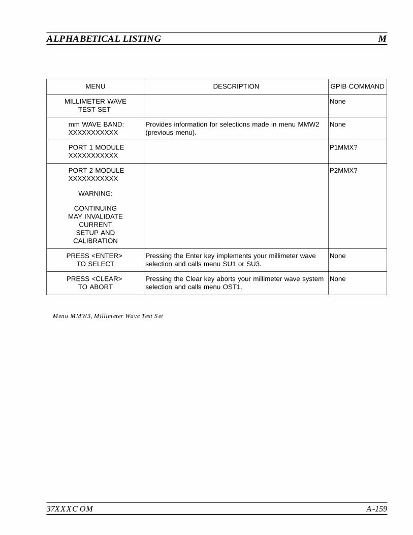
37XXXC OM A-159
ALPHABETICAL LISTING M
MENU DESCRIPTION GPIB COMMAND
MILLIMETER WAVETEST SET
None
mm WAVE BAND:XXXXXXXXXXX
Provides information for selections made in menu MMW2(previous menu).
None
PORT 1 MODULEXXXXXXXXXXX
P1MMX?
PORT 2 MODULEXXXXXXXXXXX
P2MMX?
WARNING:
CONTINUINGMAY INVALIDATE
CURRENTSETUP AND
CALIBRATION
PRESS <ENTER>TO SELECT
Pressing the Enter key implements your millimeter waveselection and calls menu SU1 or SU3.
None
PRESS <CLEAR>TO ABORT
Pressing the Clear key aborts your millimeter wave systemselection and calls menu OST1.
None
Menu MMW3, Millimeter Wave Test Set
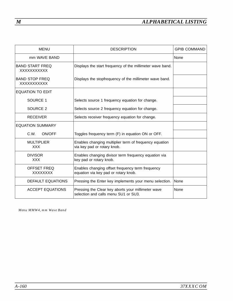
A-160 37XXXC OM
M ALPHABETICAL LISTING
MENU DESCRIPTION GPIB COMMAND
mm WAVE BAND None
BAND START FREQXXXXXXXXXXX
Displays the start frequency of the millimeter wave band.
BAND STOP FREQXXXXXXXXXXX
Displays the stopfrequency of the millimeter wave band.
EQUATION TO EDIT
SOURCE 1 Selects source 1 frequency equation for change.
SOURCE 2 Selects source 2 frequency equation for change.
RECEIVER Selects receiver frequency equation for change.
EQUATION SUMMARY
C.W. ON/OFF Toggles frequency term (F) in equation ON or OFF.
MULTIPLIERXXX
Enables changing multiplier term of frequency equationvia key pad or rotary knob.
DIVISORXXX
Enables changing divisor term frequency equation viakey pad or rotary knob.
OFFSET FREQXXXXXXXX
Enables changing offset frequency term frequencyequation via key pad or rotary knob.
DEFAULT EQUATIONS Pressing the Enter key implements your menu selection. None
ACCEPT EQUATIONS Pressing the Clear key aborts your millimeter waveselection and calls menu SU1 or SU3.
None
Menu MMW4, mm Wave Band

37XXXC OM A-161
ALPHABETICAL LISTING M
- MILLIMETER WAVE BAND DEFINITION SUMMARY -
BAND FREQUENCY RANGE
BAND START FBAND STOP FXXX.XXXXXX XXXXXX.XXXXXX XXX
FREQUENCY = (MULTIPLIER/DIVISOR) * F + OFFSET FREQ)
SOURCE 1 = (1/ 6) * (F – 0.270000 GHz)
SOURCE 2 = (1/ 8) * (F+ 0.000000 GHz)
RECEIVER = (1/ 1) * (0.270000 GHz C.W.)
- NOTES -
1. SELECT <DEFAULT EQUATIONS> TO OVERWRITE DEFINITIONWITH VALUES SUITABLE FOR THE MILLIMETER WAVE BAND.
2. SELECT <ACCEPT EQUATIONS> TO CONFIRM ANY CHANGES.
3. PERFORMANCE SPECIFICATIONS ARE VALID ONLY WHILEUSING THE DEFAULT EQUATIONS OVER THE DEFAULT BANDFREQUENCY RANGE.
4. DEVIATING FROM THE DEFAULT MAY CAUSE LOCK FAILURES.
PRESS <ENTER> TO SELECT, PRESS <CLEAR> TO ABORT
Menu EXT_MMW4
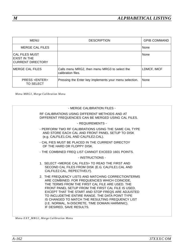
A-162 37XXXC OM
M ALPHABETICAL LISTING
MENU DESCRIPTION GPIB COMMAND
MERGE CAL FILES None
CAL FILES MUSTEXIST IN THECURRENT DIRECTORY
None
MERGE CAL FILES Calls menu MRG2, then menu MRG3 to select thecalibration files.
LDMCF, IMCF
PRESS <ENTER>TO SELECT
Pressing the Enter key implements your menu selection. None
Menu MRG1, Merge Calibration Menu
- MERGE CALIBRATION FILES -
RF CALIBRATIONS USING DIFFERENT METHODS AND ATDIFFERENT FREQUENCIES CAN BE MERGED USING CAL FILES.
- REQUIREMENTS -
- PERFORM TWO RF CALIBRATIONS USING THE SAME CAL TYPEAND STORE EACH CAL AND FRONT PANEL SETUP TO DISK(e.g. CALFILE1.CAL AND CALFILE2.CAL).
- CAL FIES MUST BE PLACED IN THE CURRENT DIRECTOYOF THE HARD OR FLOPPY DISK.
- THE COMBINED FREQ LIST CANNOT EXCEED 1601 POINTS.
- INSTRUCTIONS -
1. SELECT <MERGE CAL FILES> TO READ THE FIRST ANDSECOND CAL FILES FROM DISK (E.G. CALFILE1.CAL ANDCALFILE2.CAL, REPECTIVELY).
2. THE FREQUENCY LISTS AND MATCHING CORRECTIONTERMSARE COMBINED. FOR FREQUENCIES WHICH COINCIDE,THE TERMS FROM THE FIRST CAL FILE ARE USED. THEFRONT PANEL SETUP FROM THE FIRST CAL FILE IS USED,EXCEPT THAT THE START AND STOP FREQS ARE ADJUSTEDTO INCLUDETHE ENTIRE RANGE. THE DATA POINT TYPEIS CHANGED TO MATCH THE RESULTING FREQUENCY LIST(I.E. NORMAL, N-DISCRETE, TIME DOMAIN HARMINIC).IF DESIRED, SAVE RESULTS.
Menu EXT_MRG1, Merge Calibration Menu

37XXXC OM A-163
ALPHABETICAL LISTING M
MENU DESCRIPTION GPIB COMMAND
MERGE CAL FILES LDMCF, IMCF
READ CAL FILE 1FROM HARD DISK
Calls menu DSK2 to read the CAL file 1 in the currentdirectory of the hard disk. Completion of the file readtakes the user to menu MRG3.
None
READ CAL FILE 1FROM FLOPPY DISK
Calls menu DSK2 to read the CAL file 1 in the currentdirectory of the floppy disk. Completion of the file readtakes the user to menu MRG3.
None
PRESS <ENTER>TO SELECT
Pressing the Enter key implements your menu selection. None
PRESS <CLEAR>TO ABORT
Pressing the Clear key aborts this menu selection andreturns to menu MRG1.
None
Menu MRG2, Merge Calibration Menu
MENU DESCRIPTION GPIB COMMAND
MERGE CAL FILES LDMCF, IMCF
READ CAL FILE 2FROM HARD DISK
Calls menu DSK2 to read the CAL file 2 in the currentdirectory of the hard disk. Completion of the file readstarts the merge of the calibration terms. Finishing themerge recalls the front panel setup of the CAL file 1 anddisplays the setup menu.
None
READ CAL FILE 2FROM FLOPPY DISK
Calls menu DSK2 to read the CAL file 2 in the currentdirectory of the floppy disk. Completion of the file readstarts the merge of the calibration terms. Finishing themerge recalls the front panel setup of the CAL file 1 anddisplays the setup menu.
None
PRESS <ENTER>TO SELECT
Pressing the Enter key implements your menu selection. None
PRESS <CLEAR>TO ABORT
Pressing the Clear key aborts this menu selection andreturns to menu MRG1.
None
Menu MRG3, Merge Calibration Menu

A-164 37XXXC OM
N ALPHABETICAL LISTING
MENU DESCRIPTION GPIB COMMAND
TRACE MEMORYFUNCTIONS
None
VIEW DATA Displays measured data; that is, the data presently beingtaken.
DAT; DAT?
VIEW MEMORY Displays stored data; that is, data that was previously takenand stored in memory.
MEM
VIEW DATAAND MEMORY
Displays measured data superimposed over stored data. DTM
VIEW DATA (/)MEMORY
Displays measured data combined with stored data usingselected math.
DNM
SELECTTRACE MATH
Calls menu NO2 for selection of the type of math operationto be performed.
None
STORE DATATO MEMORY(STORED)(NOT STORED)
Stores the measured data to internal memory. STD
DISKOPERATIONS
Brings up menu NO3, which allows data to be stored to orrecalled from the disk.
None
PRESS <ENTER>TO SELECT
Pressing the Enter key implements your menu selection. None
Menu NO1, Trace Memory Functions
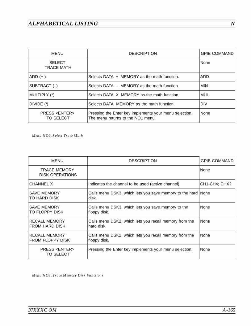
37XXXC OM A-165
ALPHABETICAL LISTING N
MENU DESCRIPTION GPIB COMMAND
SELECTTRACE MATH
None
ADD (+ ) Selects DATA + MEMORY as the math function. ADD
SUBTRACT (–) Selects DATA – MEMORY as the math function. MIN
MULTIPLY (*) Selects DATA X MEMORY as the math function. MUL
DIVIDE (/) Selects DATA MEMORY as the math function. DIV
PRESS <ENTER>TO SELECT
Pressing the Enter key implements your menu selection.The menu returns to the NO1 menu.
None
Menu NO2, Select Trace Math
MENU DESCRIPTION GPIB COMMAND
TRACE MEMORYDISK OPERATIONS
None
CHANNEL X Indicates the channel to be used (active channel). CH1-CH4; CHX?
SAVE MEMORYTO HARD DISK
Calls menu DSK3, which lets you save memory to the harddisk.
None
SAVE MEMORYTO FLOPPY DISK
Calls menu DSK3, which lets you save memory to thefloppy disk.
None
RECALL MEMORYFROM HARD DISK
Calls menu DSK2, which lets you recall memory from thehard disk.
None
RECALL MEMORYFROM FLOPPY DISK
Calls menu DSK2, which lets you recall memory from thefloppy disk.
None
PRESS <ENTER>TO SELECT
Pressing the Enter key implements your menu selection. None
Menu NO3, Trace Memory Disk Functions
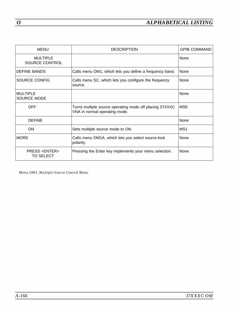
A-166 37XXXC OM
O ALPHABETICAL LISTING
MENU DESCRIPTION GPIB COMMAND
MULTIPLESOURCE CONTROL
None
DEFINE BANDS Calls menu OM1, which lets you define a frequency band. None
SOURCE CONFIG Calls menu SC, which lets you configure the frequencysource.
None
MULTIPLESOURCE MODE
None
OFF Turns multiple source operating mode off placing 37XXXCVNA in normal operating mode.
MS0
DEFINE None
ON Sets multiple source mode to ON. MS1
MORE Calls menu OM1A, which lets you select source-lockpolarity.
None
PRESS <ENTER>TO SELECT
Pressing the Enter key implements your menu selection. None
Menu OM1, Multiple Source Control Menu

37XXXC OM A-167
ALPHABETICAL LISTING O
MENU DESCRIPTION GPIB COMMAND
SOURCE LOCKPOLARITY
None
NORMALREVERSE
Calls menu OM1, which lets you define a frequency band. None
SELECT <REVERSE>SOURCE LOCKPOLARITY IF
None
THE DUT CONTAINSMULTI-CONVERSIONSTAGES, AND
None
THE PHASE OF THEFINAL OUTPUT I.F.IS OPPOSITE OFNORMAL
None
NORMAL POLARITYIS DEFINED BY THESOURCE 1 AND 2EQUATIONS
None
IF SOURCE 1 FREQIS GREATER THANSOURCE 2 FREQTHEN THE I.F.IS ASSUMED TO BEPOSITIVE POLARITYAND VICE VERSA
None
Menu OM1A, Source Lock Polarity Menu
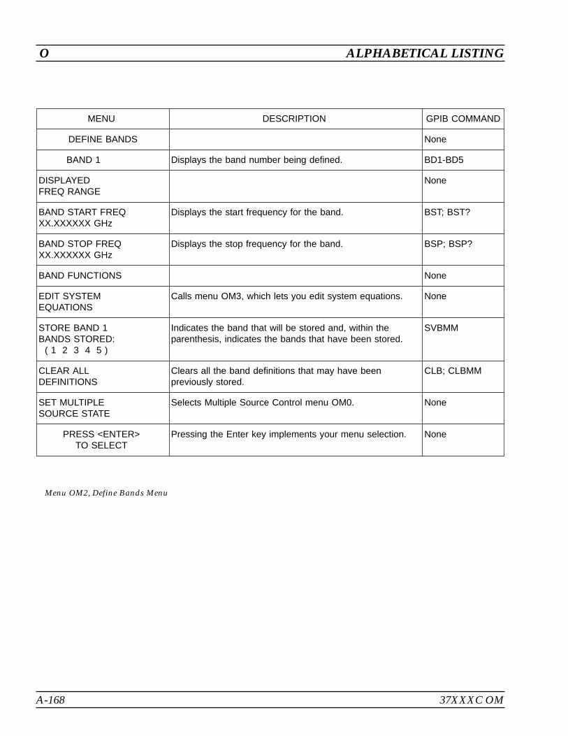
A-168 37XXXC OM
O ALPHABETICAL LISTING
MENU DESCRIPTION GPIB COMMAND
DEFINE BANDS None
BAND 1 Displays the band number being defined. BD1-BD5
DISPLAYEDFREQ RANGE
None
BAND START FREQXX.XXXXXX GHz
Displays the start frequency for the band. BST; BST?
BAND STOP FREQXX.XXXXXX GHz
Displays the stop frequency for the band. BSP; BSP?
BAND FUNCTIONS None
EDIT SYSTEMEQUATIONS
Calls menu OM3, which lets you edit system equations. None
STORE BAND 1BANDS STORED:
( 1 2 3 4 5 )
Indicates the band that will be stored and, within theparenthesis, indicates the bands that have been stored.
SVBMM
CLEAR ALLDEFINITIONS
Clears all the band definitions that may have beenpreviously stored.
CLB; CLBMM
SET MULTIPLESOURCE STATE
Selects Multiple Source Control menu OM0. None
PRESS <ENTER>TO SELECT
Pressing the Enter key implements your menu selection. None
Menu OM2, Define Bands Menu

37XXXC OM A-169
ALPHABETICAL LISTING O
MENU DESCRIPTION GPIB COMMAND
EDIT SYSTEMEQUATIONS
None
EQUATIONTO EDIT
None
SOURCE 1 Selects source 1 frequency equation for change. ED1
SOURCE 2 Selects source 2 frequency equation for change. ED2
RECEIVER Selects receiver frequency equation for change. EDR
EQUATIONSUMMARY
None
C.W. ON (OFF) Toggles frequency term (F) in equation ON or OFF. ESW; ECW;EXW?
MULTIPLIERXX
Enables changing multiplier term of frequency equation viakey pad or rotary knob.
EML
DIVISORXX
Enables changing divisor term frequency equation via keypad or rotary knob.
EDV
OFFSET FREQXXX.XXXXXXXXX GHz
Enables changing offset frequency term frequency equationvia key pad or rotary knob.
EOS; EOS?
PREVIOUS MENU Recalls menu OM1. None
PRESS <ENTER>TO SELECT
Pressing the Enter key implements your menu selection.
Menu OM3, Edit System Equations
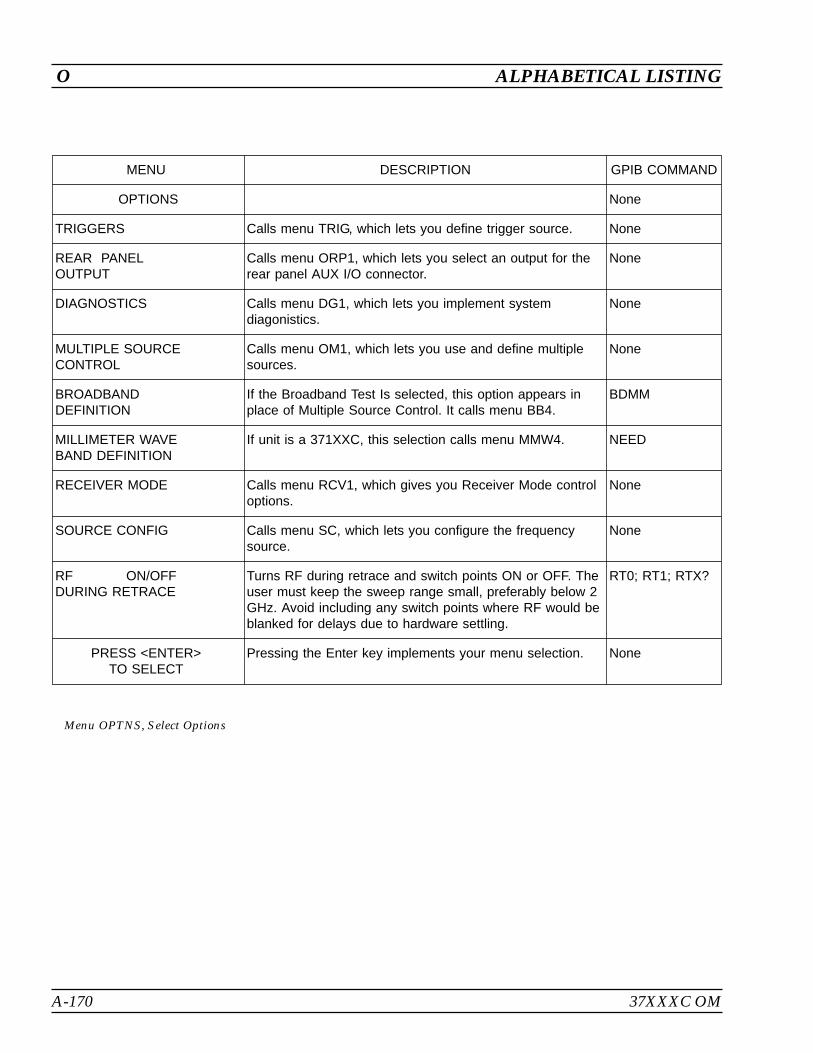
A-170 37XXXC OM
O ALPHABETICAL LISTING
MENU DESCRIPTION GPIB COMMAND
OPTIONS None
TRIGGERS Calls menu TRIG, which lets you define trigger source. None
REAR PANELOUTPUT
Calls menu ORP1, which lets you select an output for therear panel AUX I/O connector.
None
DIAGNOSTICS Calls menu DG1, which lets you implement systemdiagonistics.
None
MULTIPLE SOURCECONTROL
Calls menu OM1, which lets you use and define multiplesources.
None
BROADBANDDEFINITION
If the Broadband Test Is selected, this option appears inplace of Multiple Source Control. It calls menu BB4.
BDMM
MILLIMETER WAVEBAND DEFINITION
If unit is a 371XXC, this selection calls menu MMW4. NEED
RECEIVER MODE Calls menu RCV1, which gives you Receiver Mode controloptions.
None
SOURCE CONFIG Calls menu SC, which lets you configure the frequencysource.
None
RF ON/OFFDURING RETRACE
Turns RF during retrace and switch points ON or OFF. Theuser must keep the sweep range small, preferably below 2GHz. Avoid including any switch points where RF would beblanked for delays due to hardware settling.
RT0; RT1; RTX?
PRESS <ENTER>TO SELECT
Pressing the Enter key implements your menu selection. None
Menu OPTNS, Select Options
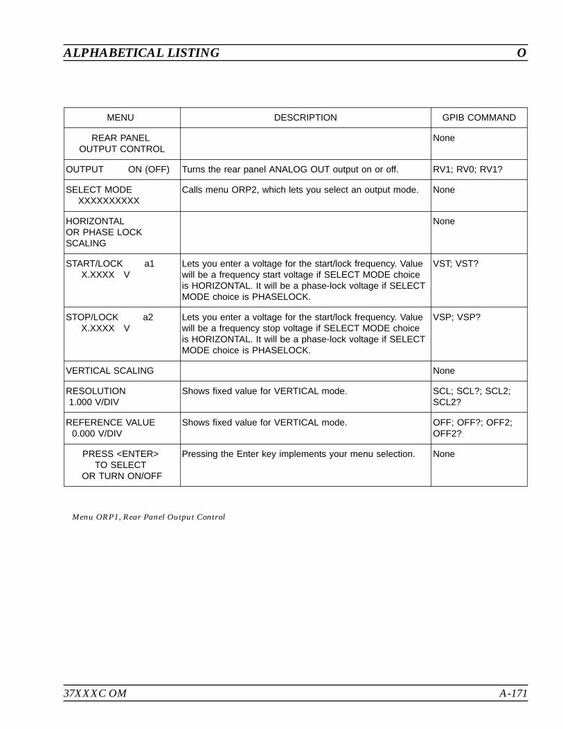
37XXXC OM A-171
ALPHABETICAL LISTING O
MENU DESCRIPTION GPIB COMMAND
REAR PANELOUTPUT CONTROL
None
OUTPUT ON (OFF) Turns the rear panel ANALOG OUT output on or off. RV1; RV0; RV1?
SELECT MODEXXXXXXXXXX
Calls menu ORP2, which lets you select an output mode. None
HORIZONTALOR PHASE LOCKSCALING
None
START/LOCK a1X.XXXX V
Lets you enter a voltage for the start/lock frequency. Valuewill be a frequency start voltage if SELECT MODE choiceis HORIZONTAL. It will be a phase-lock voltage if SELECTMODE choice is PHASELOCK.
VST; VST?
STOP/LOCK a2X.XXXX V
Lets you enter a voltage for the start/lock frequency. Valuewill be a frequency stop voltage if SELECT MODE choiceis HORIZONTAL. It will be a phase-lock voltage if SELECTMODE choice is PHASELOCK.
VSP; VSP?
VERTICAL SCALING None
RESOLUTION1.000 V/DIV
Shows fixed value for VERTICAL mode. SCL; SCL?; SCL2;SCL2?
REFERENCE VALUE0.000 V/DIV
Shows fixed value for VERTICAL mode. OFF; OFF?; OFF2;OFF2?
PRESS <ENTER>TO SELECT
OR TURN ON/OFF
Pressing the Enter key implements your menu selection. None
Menu ORP1, Rear Panel Output Control
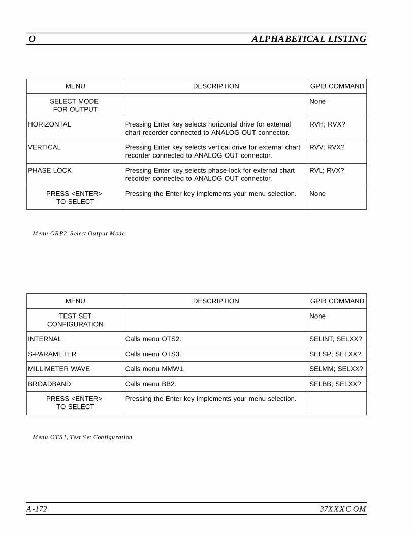
A-172 37XXXC OM
O ALPHABETICAL LISTING
MENU DESCRIPTION GPIB COMMAND
SELECT MODEFOR OUTPUT
None
HORIZONTAL Pressing Enter key selects horizontal drive for externalchart recorder connected to ANALOG OUT connector.
RVH; RVX?
VERTICAL Pressing Enter key selects vertical drive for external chartrecorder connected to ANALOG OUT connector.
RVV; RVX?
PHASE LOCK Pressing Enter key selects phase-lock for external chartrecorder connected to ANALOG OUT connector.
RVL; RVX?
PRESS <ENTER>TO SELECT
Pressing the Enter key implements your menu selection. None
Menu ORP2, Select Output Mode
MENU DESCRIPTION GPIB COMMAND
TEST SETCONFIGURATION
None
INTERNAL Calls menu OTS2. SELINT; SELXX?
S-PARAMETER Calls menu OTS3. SELSP; SELXX?
MILLIMETER WAVE Calls menu MMW1. SELMM; SELXX?
BROADBAND Calls menu BB2. SELBB; SELXX?
PRESS <ENTER>TO SELECT
Pressing the Enter key implements your menu selection.
Menu OTS1, Test Set Configuration
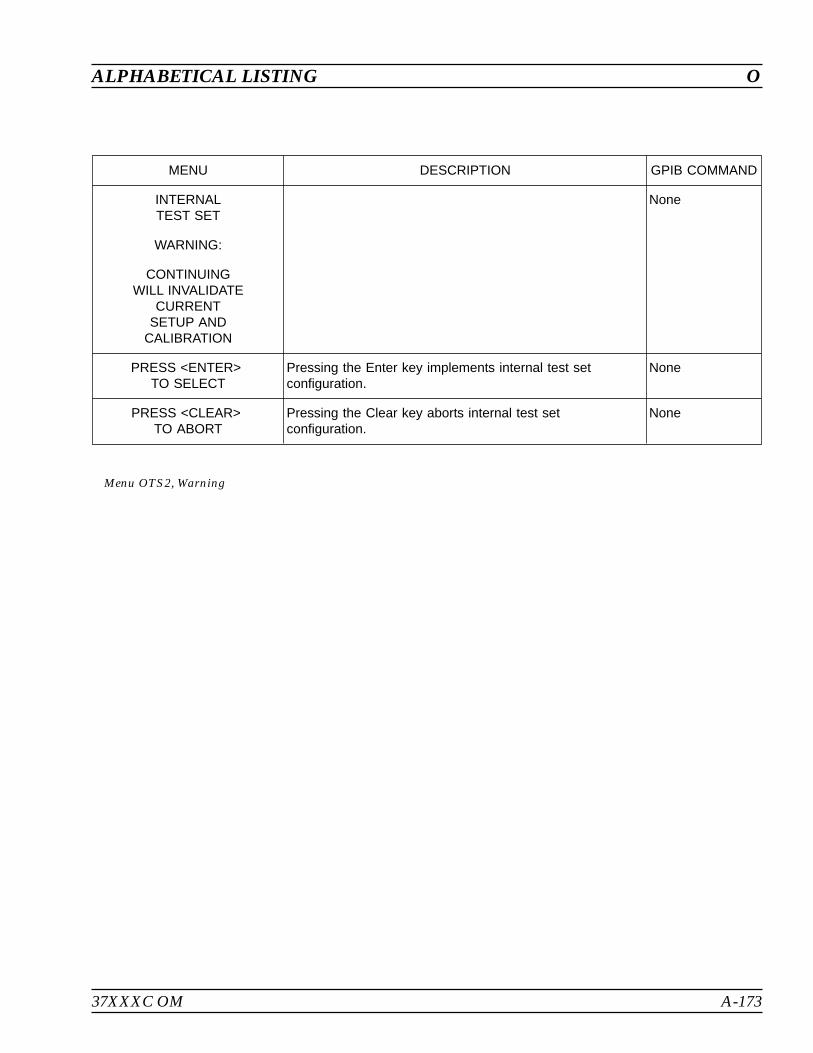
37XXXC OM A-173
ALPHABETICAL LISTING O
MENU DESCRIPTION GPIB COMMAND
INTERNALTEST SET
None
WARNING:
CONTINUINGWILL INVALIDATE
CURRENTSETUP AND
CALIBRATION
PRESS <ENTER>TO SELECT
Pressing the Enter key implements internal test setconfiguration.
None
PRESS <CLEAR>TO ABORT
Pressing the Clear key aborts internal test setconfiguration.
None
Menu OTS2, Warning
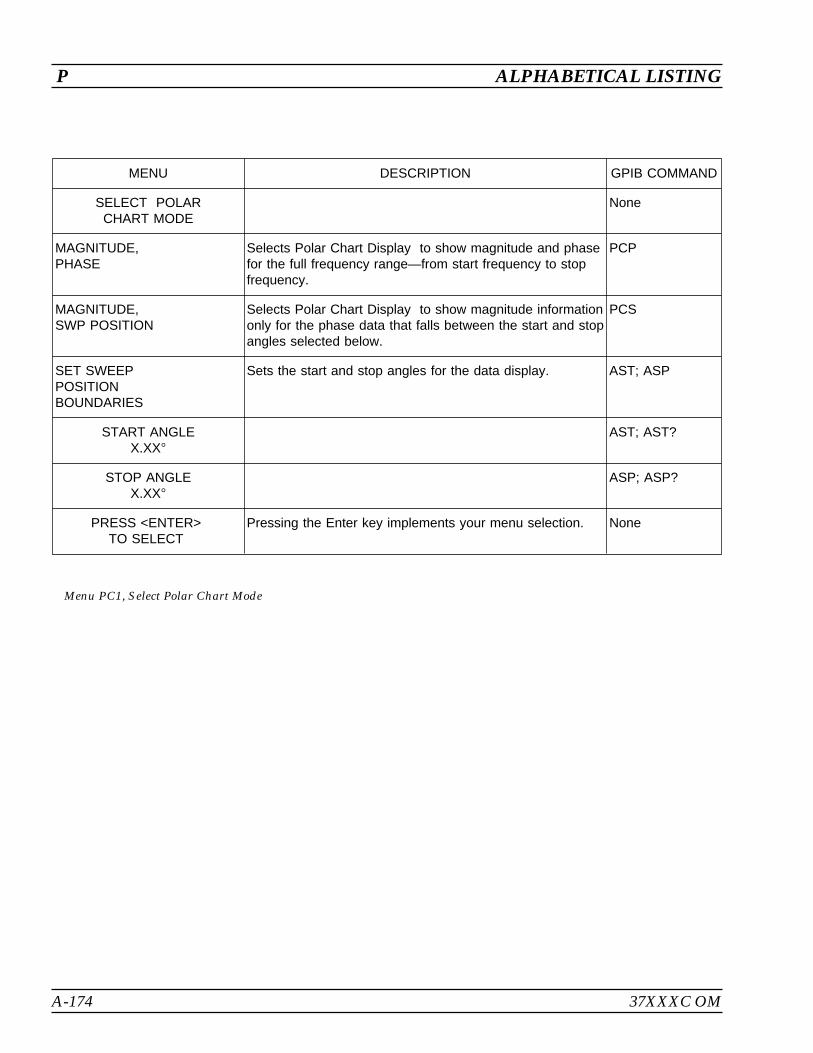
A-174 37XXXC OM
P ALPHABETICAL LISTING
MENU DESCRIPTION GPIB COMMAND
SELECT POLARCHART MODE
None
MAGNITUDE,PHASE
Selects Polar Chart Display to show magnitude and phasefor the full frequency range—from start frequency to stopfrequency.
PCP
MAGNITUDE,SWP POSITION
Selects Polar Chart Display to show magnitude informationonly for the phase data that falls between the start and stopangles selected below.
PCS
SET SWEEPPOSITIONBOUNDARIES
Sets the start and stop angles for the data display. AST; ASP
START ANGLEX.XX
AST; AST?
STOP ANGLEX.XX
ASP; ASP?
PRESS <ENTER>TO SELECT
Pressing the Enter key implements your menu selection. None
Menu PC1, Select Polar Chart Mode
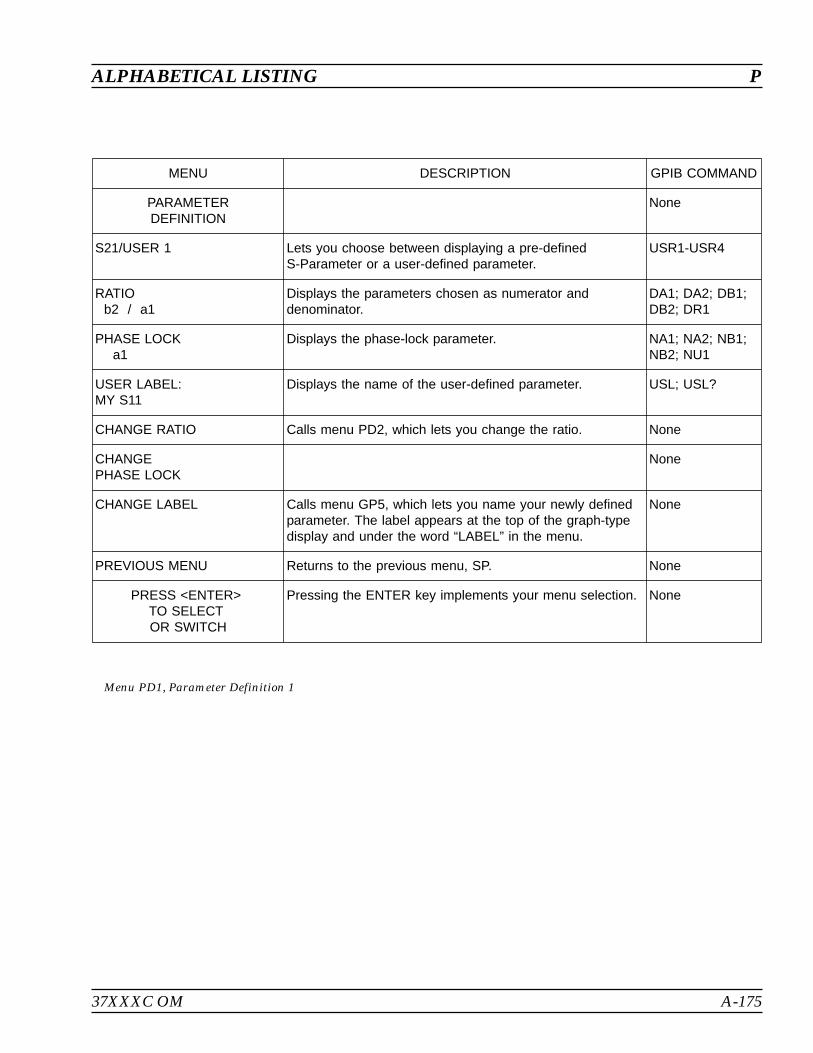
37XXXC OM A-175
ALPHABETICAL LISTING P
MENU DESCRIPTION GPIB COMMAND
PARAMETERDEFINITION
None
S21/USER 1 Lets you choose between displaying a pre-definedS-Parameter or a user-defined parameter.
USR1-USR4
RATIOb2 / a1
Displays the parameters chosen as numerator anddenominator.
DA1; DA2; DB1;DB2; DR1
PHASE LOCKa1
Displays the phase-lock parameter. NA1; NA2; NB1;NB2; NU1
USER LABEL:MY S11
Displays the name of the user-defined parameter. USL; USL?
CHANGE RATIO Calls menu PD2, which lets you change the ratio. None
CHANGEPHASE LOCK
None
CHANGE LABEL Calls menu GP5, which lets you name your newly definedparameter. The label appears at the top of the graph-typedisplay and under the word “LABEL” in the menu.
None
PREVIOUS MENU Returns to the previous menu, SP. None
PRESS <ENTER>TO SELECTOR SWITCH
Pressing the ENTER key implements your menu selection. None
Menu PD1, Parameter Definition 1
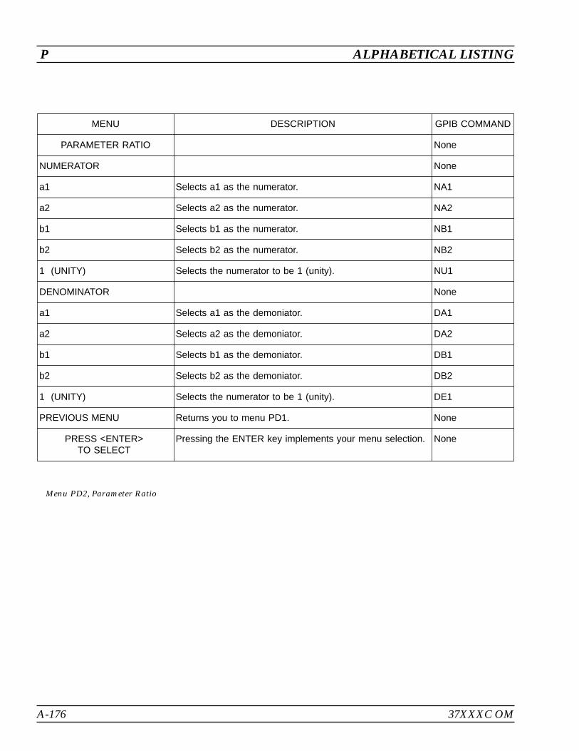
A-176 37XXXC OM
P ALPHABETICAL LISTING
MENU DESCRIPTION GPIB COMMAND
PARAMETER RATIO None
NUMERATOR None
a1 Selects a1 as the numerator. NA1
a2 Selects a2 as the numerator. NA2
b1 Selects b1 as the numerator. NB1
b2 Selects b2 as the numerator. NB2
1 (UNITY) Selects the numerator to be 1 (unity). NU1
DENOMINATOR None
a1 Selects a1 as the demoniator. DA1
a2 Selects a2 as the demoniator. DA2
b1 Selects b1 as the demoniator. DB1
b2 Selects b2 as the demoniator. DB2
1 (UNITY) Selects the numerator to be 1 (unity). DE1
PREVIOUS MENU Returns you to menu PD1. None
PRESS <ENTER>TO SELECT
Pressing the ENTER key implements your menu selection. None
Menu PD2, Parameter Ratio
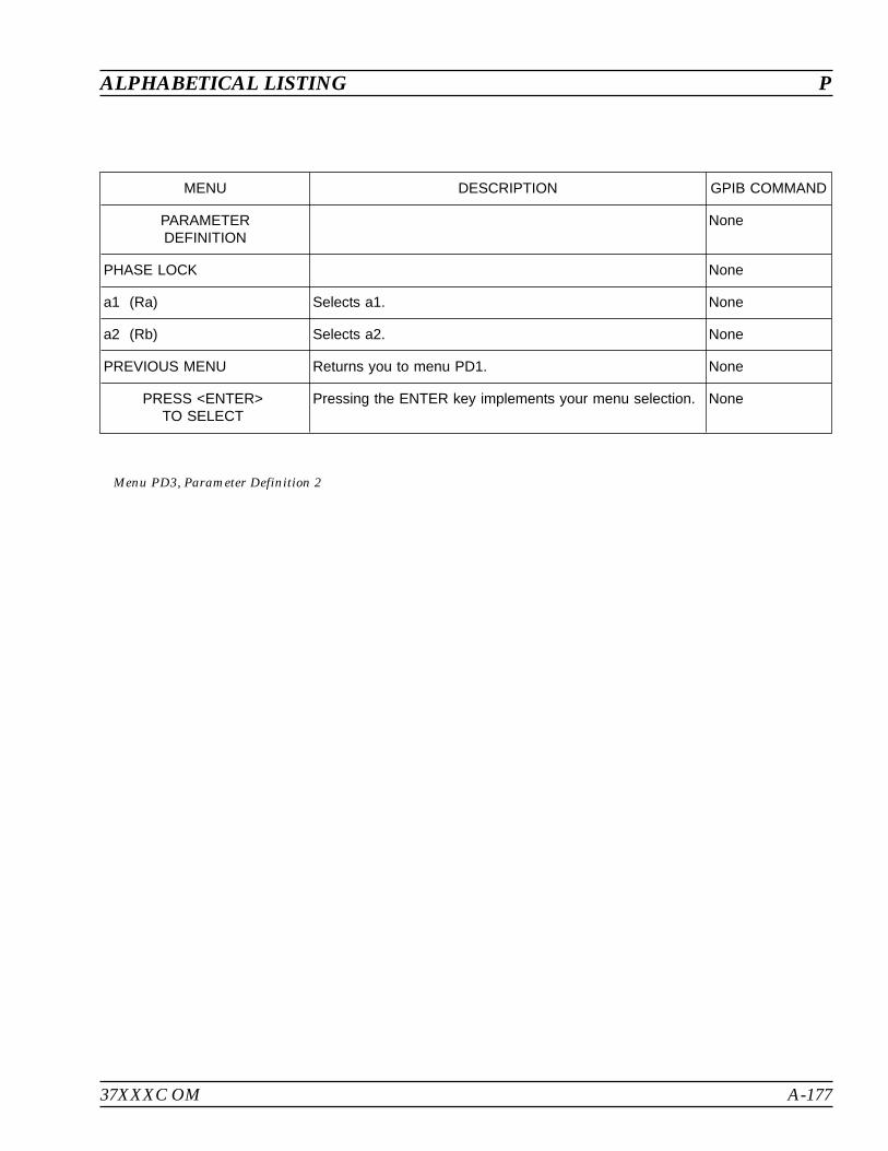
37XXXC OM A-177
ALPHABETICAL LISTING P
MENU DESCRIPTION GPIB COMMAND
PARAMETERDEFINITION
None
PHASE LOCK None
a1 (Ra) Selects a1. None
a2 (Rb) Selects a2. None
PREVIOUS MENU Returns you to menu PD1. None
PRESS <ENTER>TO SELECT
Pressing the ENTER key implements your menu selection. None
Menu PD3, Parameter Definition 2
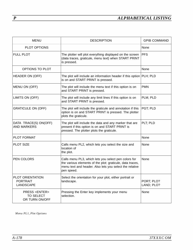
A-178 37XXXC OM
P ALPHABETICAL LISTING
MENU DESCRIPTION GPIB COMMAND
PLOT OPTIONS None
FULL PLOT The plotter will plot everything displayed on the screen(data traces, graticule, menu text) when START PRINTis pressed.
PFS
OPTIONS TO PLOT None
HEADER ON (OFF) The plot will include an information header if this optionis on and START PRINT is pressed.
PLH; PLD
MENU ON (OFF) The plot will include the menu text if this option is onand START PRINT is pressed.
PMN
LIMITS ON (OFF) The plot will include any limit lines if this option is onand START PRINT is pressed.
PLM; PLD
GRATICULE ON (OFF) The plot will include the graticule and annotation if thisoption is on and START PRINT is pressed. The plotterplots the graticule.
PGT; PLD
DATA TRACE(S) ON(OFF)AND MARKERS
The plot will include the data and any marker that arepresent if this option is on and START PRINT ispressed. The plotter plots the graticule.
PLT; PLD
PLOT FORMAT None
PLOT SIZE Calls menu PL2, which lets you select the size andlocation ofthe plot.
None
PEN COLORS Calls menu PL3, which lets you select pen colors forthe various elements of the plot: graticule, data traces,menu text and header. Also lets you select the relativepen speed.
None
PLOT ORIENTATIONPORTRAITLANDSCAPE
Select the orientation for your plot, either portrait orlandscape. PORT; PLO?
LAND; PLO?
PRESS <ENTER>TO SELECT
OR TURN ON/OFF
Pressing the Enter key implements your menuselection.
None
Menu PL1, Plot Options

37XXXC OM A-179
ALPHABETICAL LISTING P
MENU DESCRIPTION GPIB COMMAND
PLOT SIZE None
FULL SIZE Selects a full size (page) plot. PFL
–QUARTERSIZE PLOTS–
None
UPPER LEFT Selects a quarter-size plot, upper-left quadrant. PTL
UPPER RIGHT Selects a quarter-size plot, upper-right quadrant. PTR
LOWER LEFT Selects a quarter-size plot, lower-left quadrant. PBL
LOWER RIGHT Selects a quarter-size plot, lower-right quadrant. PBR
PRESS <ENTER>TO SELECT
Pressing the Enter key implements your menu selection. None
Menu PL2, Select Plot Size

A-180 37XXXC OM
P ALPHABETICAL LISTING
MENU DESCRIPTION GPIB COMMAND
SELECTPEN COLORS
None
DATA PENn
Selects the color in which the data will be plotted. Thenumber of the pen displays where the “n” is shown.
DPN
DATA TRACEOVERLAY PENn
Selects the color in which the 2nd trace in a dual traceoverlay plot will be plotted. The number of the pen displayswhere the “n” is shown.
TPN
GRATICULE PENn
Selects the color in which the graticule will be plotted. Thenumber of the pen displays where the “n” is shown.
GPN; GPN?
MARKERS ANDLIMITS PENn
Selects the color in which the markers and limits will beplotted. The number of the pen displays where the “n” isshown.
MPN; MPN?
HEADER PENn
Selects the color in which the header information will beplotted. The number of the pen displays where the “n” isshown.
HPN; HPN?
PEN SPEED100 PERCENTOF MAXIMUM
Selects the pen’s speed as a percentage of the plotter’smaximum speed. (Used to optimize plots on transparenciesor with worn pens.)
SPD; SPD?
PREVIOUS MENU Recalls menu PL1. None
PRESS <ENTER>TO SELECT
Pressing the Enter key implements your menu selection. None
Menu PL3, Select Pen Colors
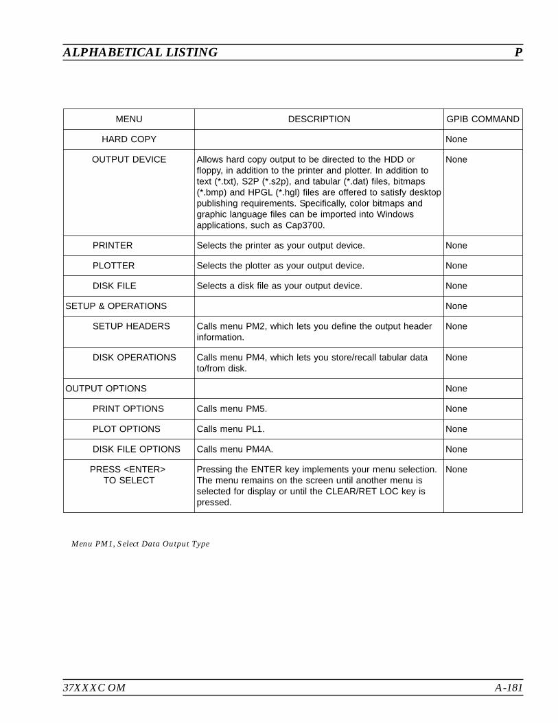
37XXXC OM A-181
ALPHABETICAL LISTING P
MENU DESCRIPTION GPIB COMMAND
HARD COPY None
OUTPUT DEVICE Allows hard copy output to be directed to the HDD orfloppy, in addition to the printer and plotter. In addition totext (*.txt), S2P (*.s2p), and tabular (*.dat) files, bitmaps(*.bmp) and HPGL (*.hgl) files are offered to satisfy desktoppublishing requirements. Specifically, color bitmaps andgraphic language files can be imported into Windowsapplications, such as Cap3700.
None
PRINTER Selects the printer as your output device. None
PLOTTER Selects the plotter as your output device. None
DISK FILE Selects a disk file as your output device. None
SETUP & OPERATIONS None
SETUP HEADERS Calls menu PM2, which lets you define the output headerinformation.
None
DISK OPERATIONS Calls menu PM4, which lets you store/recall tabular datato/from disk.
None
OUTPUT OPTIONS None
PRINT OPTIONS Calls menu PM5. None
PLOT OPTIONS Calls menu PL1. None
DISK FILE OPTIONS Calls menu PM4A. None
PRESS <ENTER>TO SELECT
Pressing the ENTER key implements your menu selection.The menu remains on the screen until another menu isselected for display or until the CLEAR/RET LOC key ispressed.
None
Menu PM1, Select Data Output Type
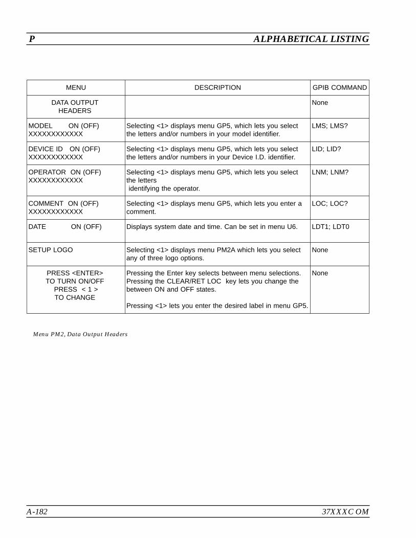
A-182 37XXXC OM
P ALPHABETICAL LISTING
MENU DESCRIPTION GPIB COMMAND
DATA OUTPUTHEADERS
None
MODEL ON (OFF)XXXXXXXXXXXX
Selecting <1> displays menu GP5, which lets you selectthe letters and/or numbers in your model identifier.
LMS; LMS?
DEVICE ID ON (OFF)XXXXXXXXXXXX
Selecting <1> displays menu GP5, which lets you selectthe letters and/or numbers in your Device I.D. identifier.
LID; LID?
OPERATOR ON (OFF)XXXXXXXXXXXX
Selecting <1> displays menu GP5, which lets you selectthe lettersidentifying the operator.
LNM; LNM?
COMMENT ON (OFF)XXXXXXXXXXXX
Selecting <1> displays menu GP5, which lets you enter acomment.
LOC; LOC?
DATE ON (OFF) Displays system date and time. Can be set in menu U6. LDT1; LDT0
SETUP LOGO Selecting <1> displays menu PM2A which lets you selectany of three logo options.
None
PRESS <ENTER>TO TURN ON/OFF
PRESS < 1 >TO CHANGE
Pressing the Enter key selects between menu selections.Pressing the CLEAR/RET LOC key lets you change thebetween ON and OFF states.
Pressing <1> lets you enter the desired label in menu GP5.
None
Menu PM2, Data Output Headers

37XXXC OM A-183
ALPHABETICAL LISTING P
MENU DESCRIPTION GPIB COMMAND
LOGO SETUP Lets you turn off the Anritsu logo and select a user-definelogo.
None
LOGO ON (OFF) Turns the logo on and off. LOGO1; LOGO0;LOGOX?
LOGO TYPE Lets you define the logo type. None
STANDARD Causes the standard logo to be displayed. LOGOS
USER LOGO Lets users display their own log. LOGOU
INSTALL USER LOGO FROMFLOPPY DISK
None
FOR PRINTER Lets you define logo for printing. None
FOR PLOTTER Lets you define logo for plotting. None
PREVIOUS MENU Returns to previous menu. None
PRESS <ENTER>TO SELECT
Pressing the Enter key selects between menu selections. None
Menu PM2A, Data Output Headers
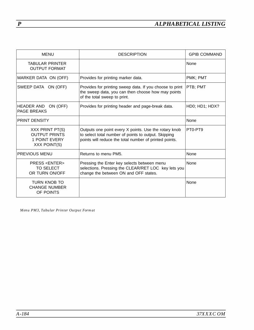
A-184 37XXXC OM
P ALPHABETICAL LISTING
MENU DESCRIPTION GPIB COMMAND
TABULAR PRINTEROUTPUT FORMAT
None
MARKER DATA ON (OFF) Provides for printing marker data. PMK; PMT
SWEEP DATA ON (OFF) Provides for printing sweep data. If you choose to printthe sweep data, you can then choose how may pointsof the total sweep to print.
PTB; PMT
HEADER AND ON (OFF)PAGE BREAKS
Provides for printing header and page-break data. HD0; HD1; HDX?
PRINT DENSITY None
XXX PRINT PT(S)OUTPUT PRINTS1 POINT EVERYXXX POINT(S)
Outputs one point every X points. Use the rotary knobto select total number of points to output. Skippingpoints will reduce the total number of printed points.
PT0-PT9
PREVIOUS MENU Returns to menu PM5. None
PRESS <ENTER>TO SELECT
OR TURN ON/OFF
Pressing the Enter key selects between menuselections. Pressing the CLEAR/RET LOC key lets youchange the between ON and OFF states.
None
TURN KNOB TOCHANGE NUMBER
OF POINTS
None
Menu PM3, Tabular Printer Output Format
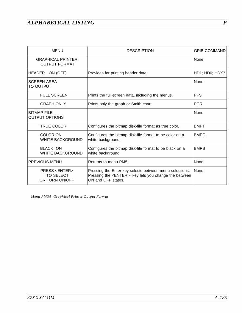
37XXXC OM A-185
ALPHABETICAL LISTING P
MENU DESCRIPTION GPIB COMMAND
GRAPHICAL PRINTEROUTPUT FORMAT
None
HEADER ON (OFF) Provides for printing header data. HD1; HD0; HDX?
SCREEN AREATO OUTPUT
None
FULL SCREEN Prints the full-screen data, including the menus. PFS
GRAPH ONLY Prints only the graph or Smith chart. PGR
BITMAP FILEOUTPUT OPTIONS
None
TRUE COLOR Configures the bitmap disk-file format as true color. BMPT
COLOR ONWHITE BACKGROUND
Configures the bitmap disk-file format to be color on awhite background.
BMPC
BLACK ONWHITE BACKGROUND
Configures the bitmap disk-file format to be black on awhite background.
BMPB
PREVIOUS MENU Returns to menu PM5. None
PRESS <ENTER>TO SELECT
OR TURN ON/OFF
Pressing the Enter key selects between menu selections.Pressing the <ENTER> key lets you change the betweenON and OFF states.
None
Menu PM3A, Graphical Printer Output Format

A-186 37XXXC OM
P ALPHABETICAL LISTING
MENU DESCRIPTION GPIB COMMAND
OUTPUTDISK OPERATIONS
None
TABULAR DATAFROM HARD DISKTO PRINTER
Calls DSK2 for selection of a measurement data file to beoutput to the printer.
None
TABULAR DATAFROM FLOPPY DISKTO PRINTER
Calls DSK2 for selection of a measurement data file to beoutput to the printer.
None
PRESS <ENTER>TO SELECT
Pressing the Enter key implements your menu selection. None
Menu PM4, Disk Output Operations
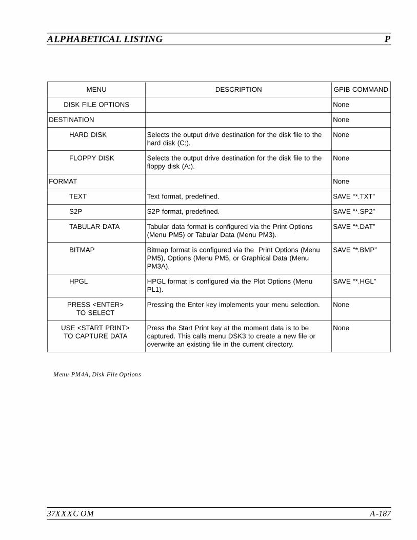
37XXXC OM A-187
ALPHABETICAL LISTING P
MENU DESCRIPTION GPIB COMMAND
DISK FILE OPTIONS None
DESTINATION None
HARD DISK Selects the output drive destination for the disk file to thehard disk (C:).
None
FLOPPY DISK Selects the output drive destination for the disk file to thefloppy disk (A:).
None
FORMAT None
TEXT Text format, predefined. SAVE “*.TXT”
S2P S2P format, predefined. SAVE “*.SP2”
TABULAR DATA Tabular data format is configured via the Print Options(Menu PM5) or Tabular Data (Menu PM3).
SAVE “*.DAT”
BITMAP Bitmap format is configured via the Print Options (MenuPM5), Options (Menu PM5, or Graphical Data (MenuPM3A).
SAVE “*.BMP”
HPGL HPGL format is configured via the Plot Options (MenuPL1).
SAVE “*.HGL”
PRESS <ENTER>TO SELECT
Pressing the Enter key implements your menu selection. None
USE <START PRINT>TO CAPTURE DATA
Press the Start Print key at the moment data is to becaptured. This calls menu DSK3 to create a new file oroverwrite an existing file in the current directory.
None
Menu PM4A, Disk File Options

A-188 37XXXC OM
P ALPHABETICAL LISTING
MENU DESCRIPTION GPIB COMMAND
PRINT OPTIONS None
PRINTER TYPE None
THINKJET Select when HP QuietJet or HP ThinkJet is connected to37XXXC VNA.
None
DESKJET Select when HP DeskJet (B/W) or HP LaserJet II and IIIseries is connected to 37XXXC VNA.
None
EPSON Select when Epson FX, Epson MX, or Epson 9-pincompatible is connected to 37XXXC VNA.
None
FORMAT OFPRINTER OUTPUT
None
GRAPHICAL DATA Prints only the graph or Smith chart, including any and alldata it contains.
None
TABULAR DATA Prints a tabulation of the measured data None
PRESS <ENTER>TO SELECT
Pressing the Enter key implements your menu selection. None
Menu PM5, Printer Type, Options

37XXXC OM A-189
ALPHABETICAL LISTING R
MENU DESCRIPTION GPIB COMMAND
RECEIVER MODE None
STANDARD Selects STANDARD mode (RECEIVER mode is notactivated).
SDR; SDR?
USER DEFINED Calls menu RCV2, which lets you define rEceiver Modeparameters.
None
SOURCE CONFIG Calls menu SC, which lets you configure the frequencysource.
None
SPUR REDUCTIONNORMAL/OFF
Switches between NORMAL and OFF for hardware spurreduction. Hardware control may not be available.
SPR1; SPR0;SPRX?
PRESS <ENTER>TO SELECTOR SWITCH
Pressing the ENTER key implements or switches yourmenu selection.
None
Menu RCV1, Receiver Mode
MENU DESCRIPTION GPIB COMMAND
STANDARDRECEIVER MODE
None
WARNING: None
CONTINUINGMAY INVALIDATECURRENT SETUPAND CALIBRATION
PRESS <ENTER>TO CONTINUE
Pressing the ENTER key implements your menu selection.
PRESS <CLEAR>TO ABORT
Pressing the CLEAR key aborts the Receiver Mode. None
Menu RCV1_WARN, Standard Receiver Mode Warning
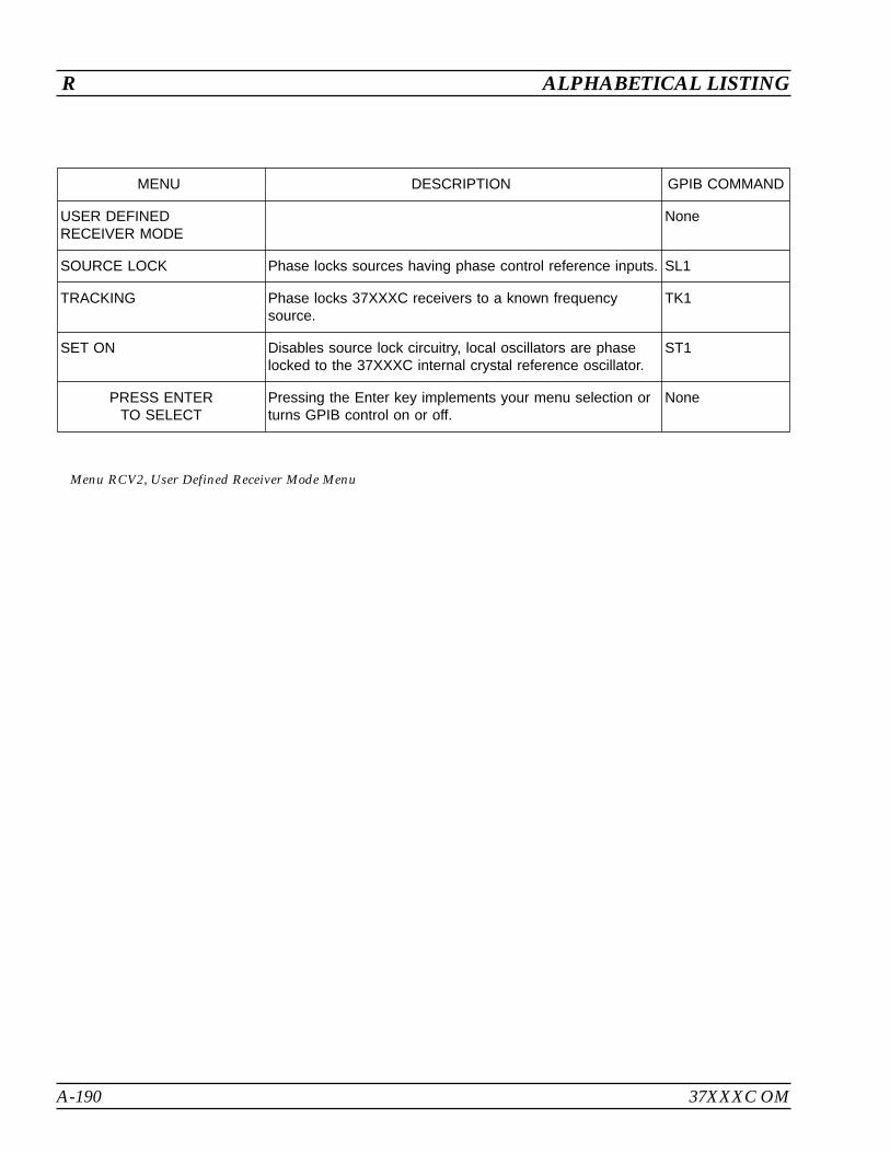
A-190 37XXXC OM
R ALPHABETICAL LISTING
MENU DESCRIPTION GPIB COMMAND
USER DEFINEDRECEIVER MODE
None
SOURCE LOCK Phase locks sources having phase control reference inputs. SL1
TRACKING Phase locks 37XXXC receivers to a known frequencysource.
TK1
SET ON Disables source lock circuitry, local oscillators are phaselocked to the 37XXXC internal crystal reference oscillator.
ST1
PRESS ENTERTO SELECT
Pressing the Enter key implements your menu selection orturns GPIB control on or off.
None
Menu RCV2, User Defined Receiver Mode Menu
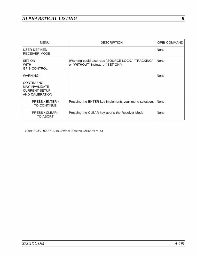
37XXXC OM A-191
ALPHABETICAL LISTING R
MENU DESCRIPTION GPIB COMMAND
USER DEFINEDRECEIVER MODE
None
SET ONWITHGPIB CONTROL
(Warning could also read “SOURCE LOCK,” “TRACKING,”or “WITHOUT” instead of “SET ON”).
None
WARNING: None
CONTINUINGMAY INVALIDATECURRENT SETUPAND CALIBRATION
PRESS <ENTER>TO CONTINUE
Pressing the ENTER key implements your menu selection. None
PRESS <CLEAR>TO ABORT
Pressing the CLEAR key aborts the Receiver Mode. None
Menu RCV2_WARN, User Defined Receiver Mode Warning

A-192 37XXXC OM
R ALPHABETICAL LISTING
MENU DESCRIPTION GPIB COMMAND
STANDARDRECEIVER MODE
Indicates that Standard Receiver mode has been selected. None
WARNING:
CONTINUINGWILL ERASE
CURRENTSETUP AND
CALIBRATION
Indicates that continuing (by pressing the Enter key) willerase current setup and calibration stored in the VNA.
None
Menu RCV3, Standard Receiver Mode Warning Menu

37XXXC OM A-193
ALPHABETICAL LISTING R
MENU DESCRIPTION GPIB COMMAND
USER DEFINEDRECEIVER MODE
None
XXXXXXXX Indicates selected mode
WARNING:
CONTINUINGWILL ERASE
CURRENTSETUP AND
CALIBRATION
Indicates that continuing (by pressing the Enter key) willerase current setup and calibration stored in theVNA.
None
PRESS <ENTER>TO CONTINUE
OR
PRESS <CLEAR>TO ABORT
Pressing Enter key implements selected mode.
Pressing the CLEAR key aborts the selected mode; currentsetup and calibration data stored in the VNA is preserved.
None
Menu RCV4, User Defined Receiver Mode Warning Menu
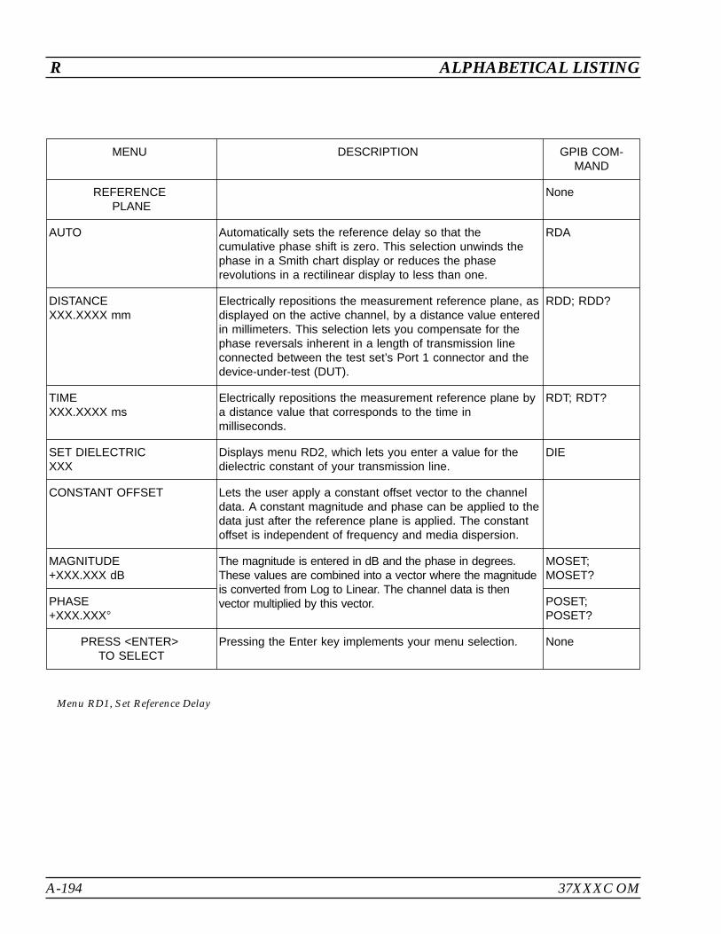
A-194 37XXXC OM
R ALPHABETICAL LISTING
MENU DESCRIPTION GPIB COM-MAND
REFERENCEPLANE
None
AUTO Automatically sets the reference delay so that thecumulative phase shift is zero. This selection unwinds thephase in a Smith chart display or reduces the phaserevolutions in a rectilinear display to less than one.
RDA
DISTANCEXXX.XXXX mm
Electrically repositions the measurement reference plane, asdisplayed on the active channel, by a distance value enteredin millimeters. This selection lets you compensate for thephase reversals inherent in a length of transmission lineconnected between the test set’s Port 1 connector and thedevice-under-test (DUT).
RDD; RDD?
TIMEXXX.XXXX ms
Electrically repositions the measurement reference plane bya distance value that corresponds to the time inmilliseconds.
RDT; RDT?
SET DIELECTRICXXX
Displays menu RD2, which lets you enter a value for thedielectric constant of your transmission line.
DIE
CONSTANT OFFSET Lets the user apply a constant offset vector to the channeldata. A constant magnitude and phase can be applied to thedata just after the reference plane is applied. The constantoffset is independent of frequency and media dispersion.
MAGNITUDE+XXX.XXX dB
The magnitude is entered in dB and the phase in degrees.These values are combined into a vector where the magnitudeis converted from Log to Linear. The channel data is thenvector multiplied by this vector.
MOSET;MOSET?
PHASE+XXX.XXX
POSET;POSET?
PRESS <ENTER>TO SELECT
Pressing the Enter key implements your menu selection. None
Menu RD1, Set Reference Delay

37XXXC OM A-195
ALPHABETICAL LISTING R
MENU DESCRIPTION GPIB COMMAND
SETDIELECTRICCONSTANT
None
AIR(1.000649)
Calculates reference delay based on dielectric constant ofair (1.000649).
DIA
POLYETHYLENE(2.26)
Calculates reference delay based on the dielectric constantof polyethylene (2.26).
DIP
TEFLON(2.10)
Calculates reference delay based on the dielectric constantofteflon (2.1).
DIT
MICROPOROUSTEFLON(1.69)
Calculates reference delay based on the dielectric constantof microporous teflon (1.69).
DIM
OTHERXXXX.XX
Calculates reference delay based on the value you enter.Terminate your entry using any terminator and select withthe Enter key.
DIE
PRESS <ENTER>TO SELECT
Pressing the Enter key implements your menu selectionand returns you to the RD1 menu.
None
Menu RD2, Set Dielectric Constant
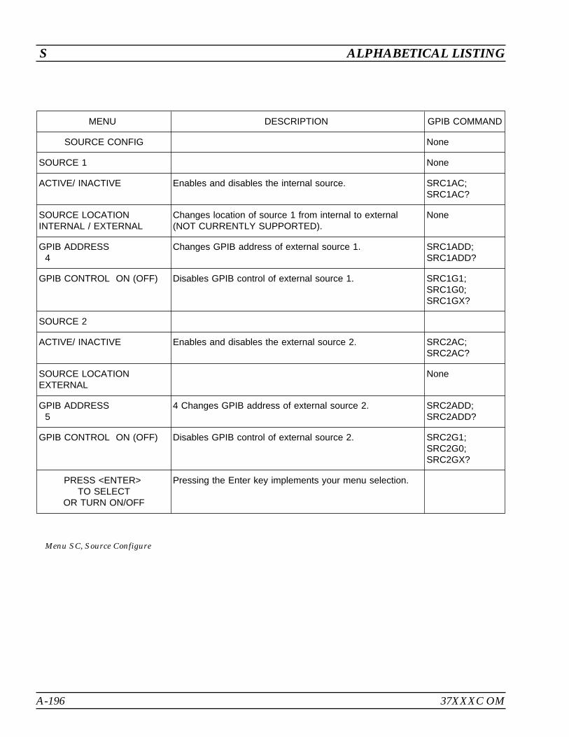
A-196 37XXXC OM
S ALPHABETICAL LISTING
MENU DESCRIPTION GPIB COMMAND
SOURCE CONFIG None
SOURCE 1 None
ACTIVE/ INACTIVE Enables and disables the internal source. SRC1AC;SRC1AC?
SOURCE LOCATIONINTERNAL / EXTERNAL
Changes location of source 1 from internal to external(NOT CURRENTLY SUPPORTED).
None
GPIB ADDRESS4
Changes GPIB address of external source 1. SRC1ADD;SRC1ADD?
GPIB CONTROL ON (OFF) Disables GPIB control of external source 1. SRC1G1;SRC1G0;SRC1GX?
SOURCE 2
ACTIVE/ INACTIVE Enables and disables the external source 2. SRC2AC;SRC2AC?
SOURCE LOCATIONEXTERNAL
None
GPIB ADDRESS5
4 Changes GPIB address of external source 2. SRC2ADD;SRC2ADD?
GPIB CONTROL ON (OFF) Disables GPIB control of external source 2. SRC2G1;SRC2G0;SRC2GX?
PRESS <ENTER>TO SELECT
OR TURN ON/OFF
Pressing the Enter key implements your menu selection.
Menu SC, Source Configure
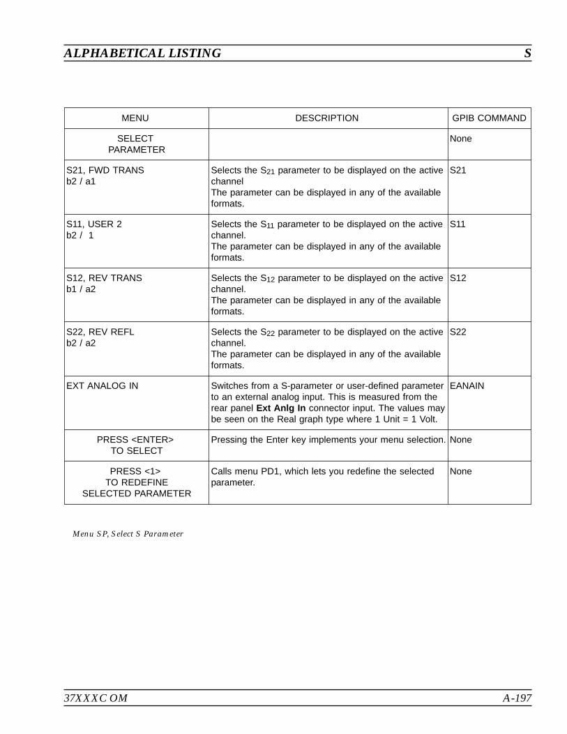
37XXXC OM A-197
ALPHABETICAL LISTING S
MENU DESCRIPTION GPIB COMMAND
SELECTPARAMETER
None
S21, FWD TRANSb2 / a1
Selects the S21 parameter to be displayed on the activechannelThe parameter can be displayed in any of the availableformats.
S21
S11, USER 2b2 / 1
Selects the S11 parameter to be displayed on the activechannel.The parameter can be displayed in any of the availableformats.
S11
S12, REV TRANSb1 / a2
Selects the S12 parameter to be displayed on the activechannel.The parameter can be displayed in any of the availableformats.
S12
S22, REV REFLb2 / a2
Selects the S22 parameter to be displayed on the activechannel.The parameter can be displayed in any of the availableformats.
S22
EXT ANALOG IN Switches from a S-parameter or user-defined parameterto an external analog input. This is measured from therear panel Ext Anlg In connector input. The values maybe seen on the Real graph type where 1 Unit = 1 Volt.
EANAIN
PRESS <ENTER>TO SELECT
Pressing the Enter key implements your menu selection. None
PRESS <1>TO REDEFINE
SELECTED PARAMETER
Calls menu PD1, which lets you redefine the selectedparameter.
None
Menu SP, Select S Parameter
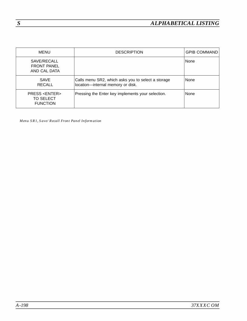
A-198 37XXXC OM
S ALPHABETICAL LISTING
MENU DESCRIPTION GPIB COMMAND
SAVE/RECALLFRONT PANELAND CAL DATA
None
SAVERECALL
Calls menu SR2, which asks you to select a storagelocation—internal memory or disk.
None
PRESS <ENTER>TO SELECTFUNCTION
Pressing the Enter key implements your selection. None
Menu SR1, Save/Recall Front Panel Information
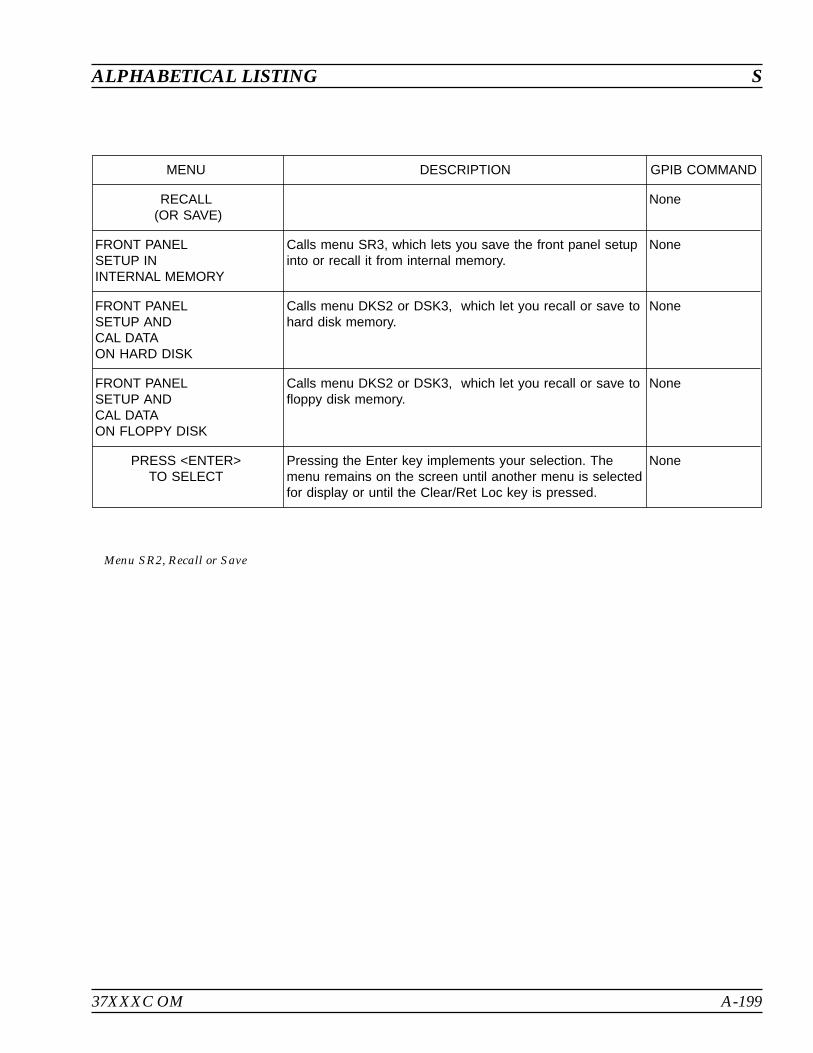
37XXXC OM A-199
ALPHABETICAL LISTING S
MENU DESCRIPTION GPIB COMMAND
RECALL(OR SAVE)
None
FRONT PANELSETUP ININTERNAL MEMORY
Calls menu SR3, which lets you save the front panel setupinto or recall it from internal memory.
None
FRONT PANELSETUP ANDCAL DATAON HARD DISK
Calls menu DKS2 or DSK3, which let you recall or save tohard disk memory.
None
FRONT PANELSETUP ANDCAL DATAON FLOPPY DISK
Calls menu DKS2 or DSK3, which let you recall or save tofloppy disk memory.
None
PRESS <ENTER>TO SELECT
Pressing the Enter key implements your selection. Themenu remains on the screen until another menu is selectedfor display or until the Clear/Ret Loc key is pressed.
None
Menu SR2, Recall or Save
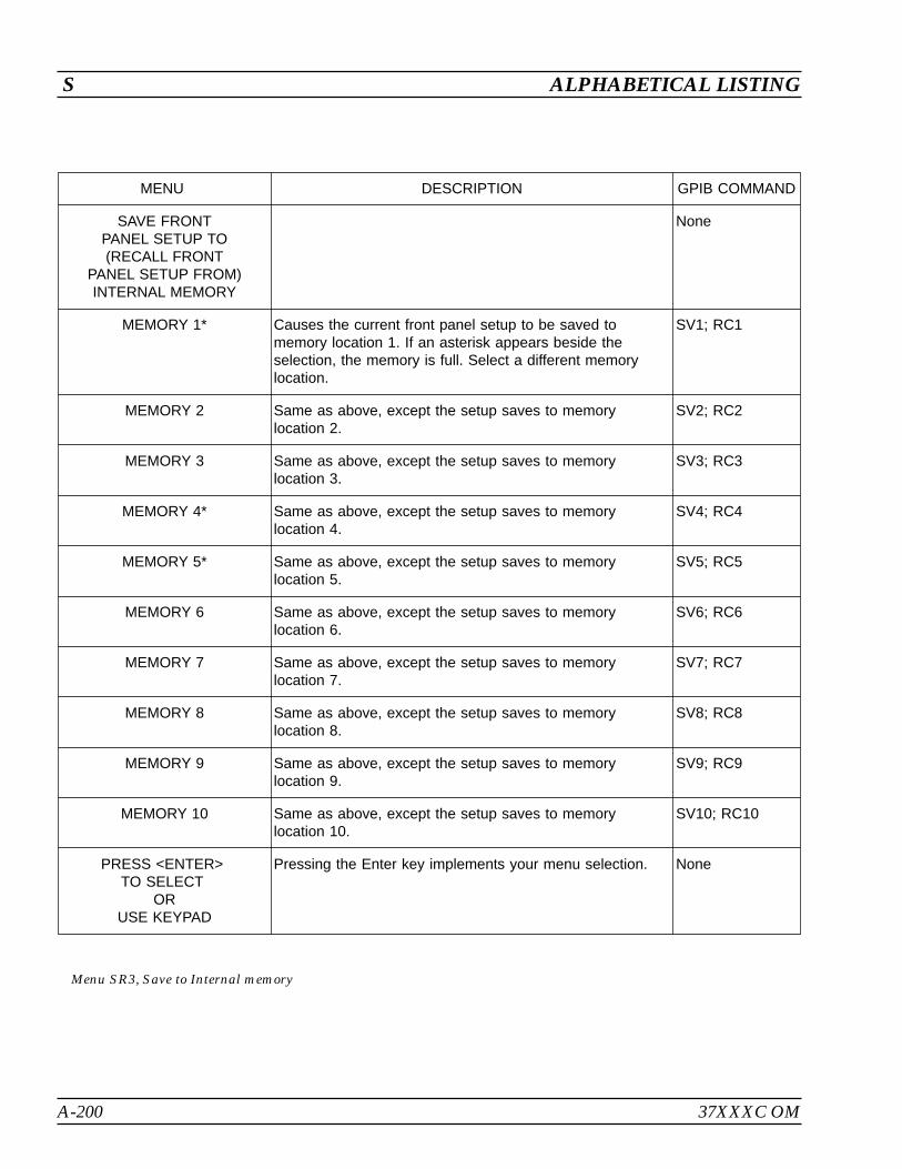
A-200 37XXXC OM
S ALPHABETICAL LISTING
MENU DESCRIPTION GPIB COMMAND
SAVE FRONTPANEL SETUP TO(RECALL FRONT
PANEL SETUP FROM)INTERNAL MEMORY
None
MEMORY 1* Causes the current front panel setup to be saved tomemory location 1. If an asterisk appears beside theselection, the memory is full. Select a different memorylocation.
SV1; RC1
MEMORY 2 Same as above, except the setup saves to memorylocation 2.
SV2; RC2
MEMORY 3 Same as above, except the setup saves to memorylocation 3.
SV3; RC3
MEMORY 4* Same as above, except the setup saves to memorylocation 4.
SV4; RC4
MEMORY 5* Same as above, except the setup saves to memorylocation 5.
SV5; RC5
MEMORY 6 Same as above, except the setup saves to memorylocation 6.
SV6; RC6
MEMORY 7 Same as above, except the setup saves to memorylocation 7.
SV7; RC7
MEMORY 8 Same as above, except the setup saves to memorylocation 8.
SV8; RC8
MEMORY 9 Same as above, except the setup saves to memorylocation 9.
SV9; RC9
MEMORY 10 Same as above, except the setup saves to memorylocation 10.
SV10; RC10
PRESS <ENTER>TO SELECT
ORUSE KEYPAD
Pressing the Enter key implements your menu selection. None
Menu SR3, Save to Internal memory

37XXXC OM A-201
ALPHABETICAL LISTING S
MENU DESCRIPTION GPIB COMMAND
SET SCALINGOR PRESS
<AUTOSCALE>
None
–LOG MAG– None
RESOLUTIONXX.XXX dB/DIV
Sets the resolution for the vertical axis of the activechannel’s displayed graph. Resolution can by setincrementally using the keypad or rotary knob.
SCL; SCL?;SCL2; SCL2?
REFERENCE VALUEXXX.XXX dB
Sets the value at the reference line for the active channelamplitude measurement on the log-magnitude graph. Thevalue can be set in increments of 0.001 dB using thekeypad or rotary knob.
OFF; OFF?OFF2; OFF2?
REFERENCE LINEX
Sets the reference line for the active channel’s amplitudemeasurement on the log-magnitude graph. This is the lineabout which the amplitude expands with different resolutionvalues. The reference line can be set to any verticaldivision using the rotary knob.
REF; REF?;REF2; REF2?
–PHASE– None
RESOLUTIONXX.XX /DIV
Sets the resolution for the vertical axis of the activechannel’s displayed phase graph. Resolution can by setincrementally usingthe keypad or rotary knob.
SCL; SCL?;SCL2; SCL2?
REFERENCE VALUEXXX.XX
Sets the value at the reference line for the active channelamplitude measurement on the phase graph. The valuecan be set in increments of 0.001 dB using the keypad orrotary knob.
OFF; OFF?OFF2; OFF2?
REFERENCE LINEX
Sets the reference line for the active channel’s phasemeasurement on the phase graph. This is the line aboutwhich the phase expands with different resolution values.The reference line can be set to any vertical division usingthe rotary knob.
REF; REF?;REF2; REF2?
PHASE SHIFTX.XX
Sets the value by which the active channel’s phasemeasurement is shifted on the phase graph. The shift canbe set in increments of 0.01 degrees using the keypad orrotary knob. This is useful when phase data is near the 180degree rollover value.
PHO; PHO?
PRESS <ENTER>TO RESUME CAL
On the CAL_SS1 menu, pressing the Enter key returns youto the calibration setup or sequence.
None
Menu SS1 or CAL_SS1, Set Scaling 1

A-202 37XXXC OM
S ALPHABETICAL LISTING
MENU DESCRIPTION GPIB COMMAND
SET SCALINGOR PRESS
<AUTOSCALE>
None
–LINEAR POLAR– None
RESOLUTIONXX.XXX U/DIV
Sets the resolution for the vertical axis of the activechannel’s displayed graph. Resolution can by setincrementally using the keypad or rotary knob. The centeris fixed at 0 units; therefore, changing the resolution alsochanges the reference value and vice versa
SCL; SCL?;SCL2; SCL2?
REFERENCE VALUEXXX.XXX U
Sets the value at the reference line for the active channelamplitude measurement on the displayed graph. The valuecan be set in increments of 0.001 U using the keypad orrotary knob.
OFF; OFF?OFF2; OFF2?
FIXEDREFERENCE LINE
Sets the reference line for the active channel’s amplitudemeasurement. This is the line about which the amplitudeexpands with different resolution values. The reference linecan be set to any vertical division using the rotary knob.
REF; REF?;REF2; REF2?
SELECT POLARCHART MODE
MAGNITUDEPHASE
Calls menu PC1, which lets you define the phase anglesbetween which your polar chart will display data.
None
PRESS <ENTER>TO SELECT
AND RESUME CAL
Pressing the Enter key implements your menu selectionand resumes the calibration from where it left off, if in thecalibration mode.
None
Menu SS2 or CAL_SS2, Set Scaling 2
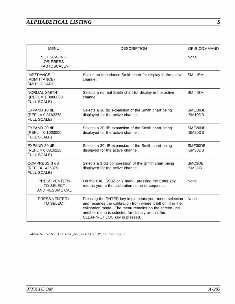
37XXXC OM A-203
ALPHABETICAL LISTING S
MENU DESCRIPTION GPIB COMMAND
SET SCALINGOR PRESS
<AUTOSCALE>
None
IMPEDANCE(ADMITTANCE)SMITH CHART
Scales an Impedance Smith chart for display in the activechannel.
SMI; ISM
NORMAL SMITH(REFL = 1.0000000
FULL SCALE)
Selects a normal Smith chart for display in the activechannel.
SMI; ISM
EXPAND 10 dB(REFL = 0.3162278FULL SCALE)
Selects a 10 dB expansion of the Smith chart beingdisplayed for the active channel.
SME10DB;ISM10DB
EXPAND 20 dB(REFL = 0.1000000FULL SCALE)
Selects a 20 dB expansion of the Smith chart beingdisplayed for the active channel.
SME20DB;ISM20DB
EXPAND 30 dB(REFL = 0.0316228FULL SCALE)
Selects a 30 dB expansion of the Smith chart beingdisplayed for the active channel.
SME30DB;ISM30DB
COMPRESS 3 dB(REFL =1.425375FULL SCALE)
Selects a 3 dB compression of the Smith chart beingdisplayed for the active channel.
SMC3DB;ISM3DB
PRESS <ENTER>TO SELECT
AND RESUME CAL
On the CAL_SS3Z or Y menu, pressing the Enter keyreturns you to the calibration setup or sequence.
None
PRESS <ENTER>TO SELECT
Pressing the ENTER key implements your menu selectionand resumes the calibration from where it left off, if in thecalibration mode.. The menu remains on the screen untilanother menu is selected for display or until theCLEAR/RET LOC key is pressed.
None
Menu SS3Z/SS3Y or CAL_SS3Z/CALSS3Y, Set Scaling 3
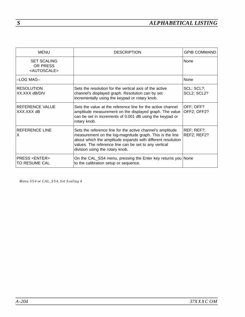
A-204 37XXXC OM
S ALPHABETICAL LISTING
MENU DESCRIPTION GPIB COMMAND
SET SCALINGOR PRESS
<AUTOSCALE>
None
–LOG MAG– None
RESOLUTIONXX.XXX dB/DIV
Sets the resolution for the vertical axis of the activechannel’s displayed graph. Resolution can by setincrementally using the keypad or rotary knob.
SCL; SCL?;SCL2; SCL2?
REFERENCE VALUEXXX.XXX dB
Sets the value at the reference line for the active channelamplitude measurement on the displayed graph. The valuecan be set in increments of 0.001 dB using the keypad orrotary knob.
OFF; OFF?OFF2; OFF2?
REFERENCE LINEX
Sets the reference line for the active channel’s amplitudemeasurement on the log-magnitude graph. This is the lineabout which the amplitude expands with different resolutionvalues. The reference line can be set to any verticaldivision using the rotary knob.
REF; REF?;REF2; REF2?
PRESS <ENTER>TO RESUME CAL
On the CAL_SS4 menu, pressing the Enter key returns youto the calibration setup or sequence.
None
Menu SS4 or CAL_SS4, Set Scaling 4
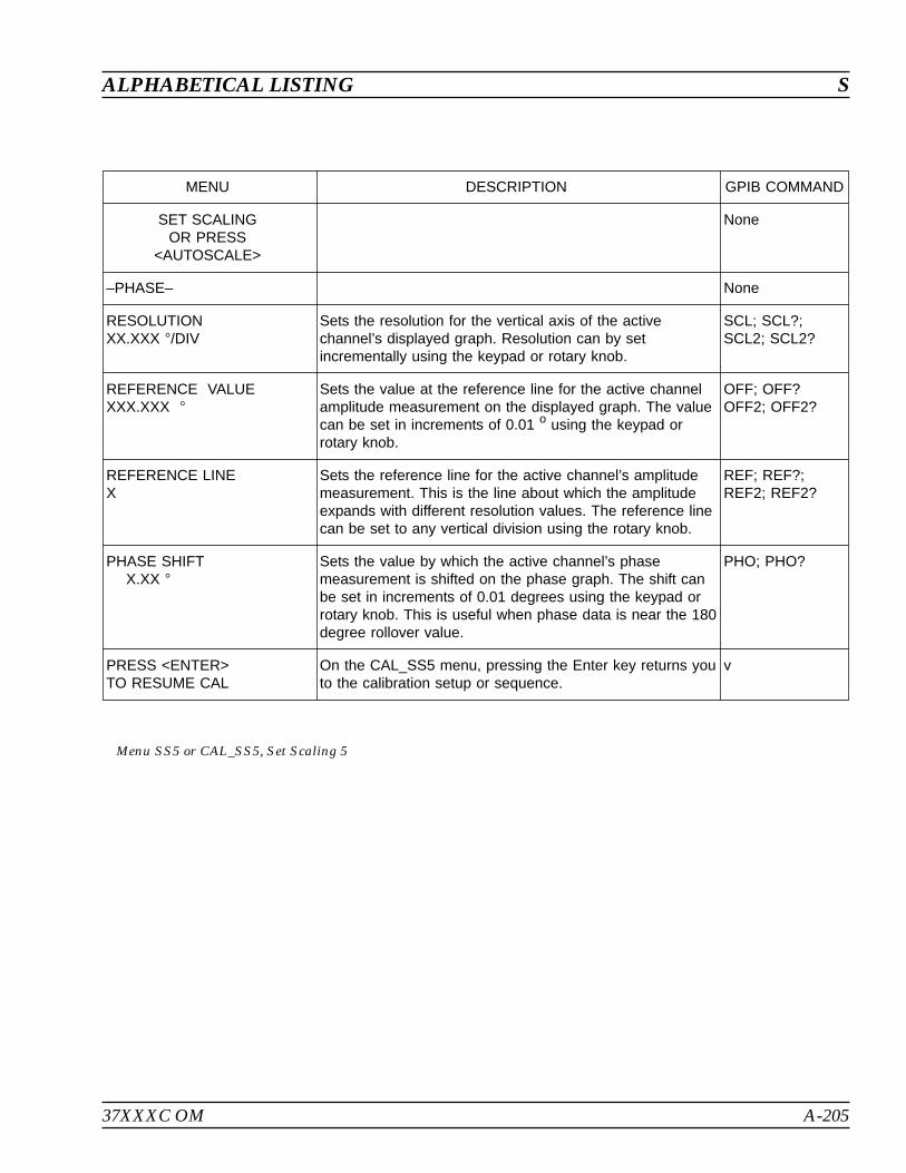
37XXXC OM A-205
ALPHABETICAL LISTING S
MENU DESCRIPTION GPIB COMMAND
SET SCALINGOR PRESS
<AUTOSCALE>
None
–PHASE– None
RESOLUTIONXX.XXX /DIV
Sets the resolution for the vertical axis of the activechannel’s displayed graph. Resolution can by setincrementally using the keypad or rotary knob.
SCL; SCL?;SCL2; SCL2?
REFERENCE VALUEXXX.XXX
Sets the value at the reference line for the active channelamplitude measurement on the displayed graph. The valuecan be set in increments of 0.01 o using the keypad orrotary knob.
OFF; OFF?OFF2; OFF2?
REFERENCE LINEX
Sets the reference line for the active channel’s amplitudemeasurement. This is the line about which the amplitudeexpands with different resolution values. The reference linecan be set to any vertical division using the rotary knob.
REF; REF?;REF2; REF2?
PHASE SHIFTX.XX
Sets the value by which the active channel’s phasemeasurement is shifted on the phase graph. The shift canbe set in increments of 0.01 degrees using the keypad orrotary knob. This is useful when phase data is near the 180degree rollover value.
PHO; PHO?
PRESS <ENTER>TO RESUME CAL
On the CAL_SS5 menu, pressing the Enter key returns youto the calibration setup or sequence.
v
Menu SS5 or CAL_SS5, Set Scaling 5

A-206 37XXXC OM
S ALPHABETICAL LISTING
MENU DESCRIPTION GPIB COMMAND
SET SCALINGOR PRESS
<AUTOSCALE>
None
–LOG POLAR– None
RESOLUTIONXX.XXX dB/DIV
Sets the resolution for the vertical axis of the activechannel’s displayed graph. Resolution can by setincrementally using the keypad or rotary knob.
SCL; SCL?;SCL2; SCL2?
REFERENCE VALUEXXX.XXX dB
Sets the value at the reference line for the active channelamplitude measurement on the displayed graph. The valuecan be set in increments of 0.001 dB using the keypad orrotary knob.
OFF; OFF?OFF2; OFF2?
FIXEDREFERENCE LINE
Sets the reference line for the active channel’s amplitudemeasurement. This is the line about which the amplitudeexpands with different resolution values. The reference linecan be set to any vertical division using the rotary knob.
REF; REF?;REF2; REF2?
SELECT POLARCHART MODE
MAGNITUDEPHASE
Calls menu PC1, which lets you define the phase anglesbetween which your polar chart will display data.
None
PRESS <ENTER>TO SELECT
AND RESUME CAL
Pressing the Enter key implements your menu selectionand resumes the calibration from where it left off, if in thecalibration mode.
None
Menu SS6 or CAL_SS6, Set Scaling 6
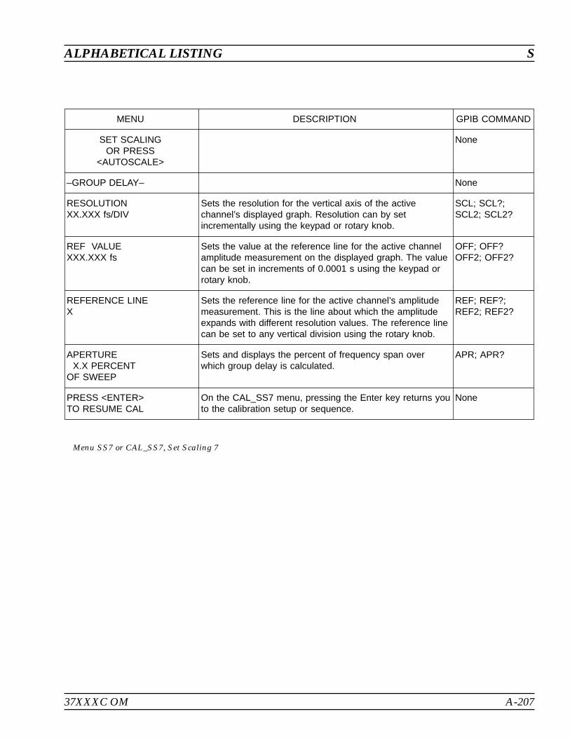
37XXXC OM A-207
ALPHABETICAL LISTING S
MENU DESCRIPTION GPIB COMMAND
SET SCALINGOR PRESS
<AUTOSCALE>
None
–GROUP DELAY– None
RESOLUTIONXX.XXX fs/DIV
Sets the resolution for the vertical axis of the activechannel’s displayed graph. Resolution can by setincrementally using the keypad or rotary knob.
SCL; SCL?;SCL2; SCL2?
REF VALUEXXX.XXX fs
Sets the value at the reference line for the active channelamplitude measurement on the displayed graph. The valuecan be set in increments of 0.0001 s using the keypad orrotary knob.
OFF; OFF?OFF2; OFF2?
REFERENCE LINEX
Sets the reference line for the active channel’s amplitudemeasurement. This is the line about which the amplitudeexpands with different resolution values. The reference linecan be set to any vertical division using the rotary knob.
REF; REF?;REF2; REF2?
APERTUREX.X PERCENT
OF SWEEP
Sets and displays the percent of frequency span overwhich group delay is calculated.
APR; APR?
PRESS <ENTER>TO RESUME CAL
On the CAL_SS7 menu, pressing the Enter key returns youto the calibration setup or sequence.
None
Menu SS7 or CAL_SS7, Set Scaling 7
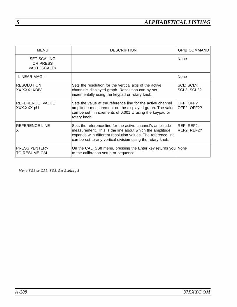
A-208 37XXXC OM
S ALPHABETICAL LISTING
MENU DESCRIPTION GPIB COMMAND
SET SCALINGOR PRESS
<AUTOSCALE>
None
–LINEAR MAG– None
RESOLUTIONXX.XXX U/DIV
Sets the resolution for the vertical axis of the activechannel’s displayed graph. Resolution can by setincrementally using the keypad or rotary knob.
SCL; SCL?;SCL2; SCL2?
REFERENCE VALUEXXX.XXX pU
Sets the value at the reference line for the active channelamplitude measurement on the displayed graph. The valuecan be set in increments of 0.001 U using the keypad orrotary knob.
OFF; OFF?OFF2; OFF2?
REFERENCE LINEX
Sets the reference line for the active channel’s amplitudemeasurement. This is the line about which the amplitudeexpands with different resolution values. The reference linecan be set to any vertical division using the rotary knob.
REF; REF?;REF2; REF2?
PRESS <ENTER>TO RESUME CAL
On the CAL_SS8 menu, pressing the Enter key returns youto the calibration setup or sequence.
None
Menu SS8 or CAL_SS8, Set Scaling 8
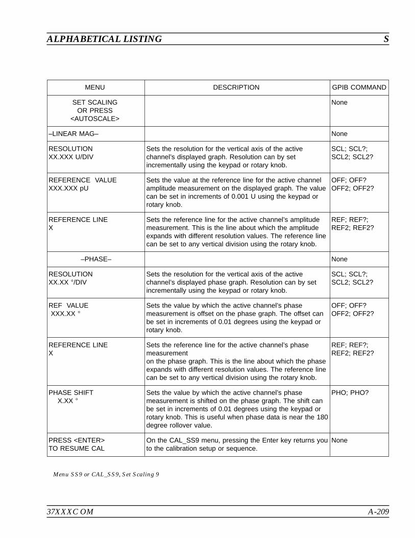
37XXXC OM A-209
ALPHABETICAL LISTING S
MENU DESCRIPTION GPIB COMMAND
SET SCALINGOR PRESS
<AUTOSCALE>
None
–LINEAR MAG– None
RESOLUTIONXX.XXX U/DIV
Sets the resolution for the vertical axis of the activechannel’s displayed graph. Resolution can by setincrementally using the keypad or rotary knob.
SCL; SCL?;SCL2; SCL2?
REFERENCE VALUEXXX.XXX pU
Sets the value at the reference line for the active channelamplitude measurement on the displayed graph. The valuecan be set in increments of 0.001 U using the keypad orrotary knob.
OFF; OFF?OFF2; OFF2?
REFERENCE LINEX
Sets the reference line for the active channel’s amplitudemeasurement. This is the line about which the amplitudeexpands with different resolution values. The reference linecan be set to any vertical division using the rotary knob.
REF; REF?;REF2; REF2?
–PHASE– None
RESOLUTIONXX.XX /DIV
Sets the resolution for the vertical axis of the activechannel’s displayed phase graph. Resolution can by setincrementally using the keypad or rotary knob.
SCL; SCL?;SCL2; SCL2?
REF VALUEXXX.XX
Sets the value by which the active channel’s phasemeasurement is offset on the phase graph. The offset canbe set in increments of 0.01 degrees using the keypad orrotary knob.
OFF; OFF?OFF2; OFF2?
REFERENCE LINEX
Sets the reference line for the active channel’s phasemeasurementon the phase graph. This is the line about which the phaseexpands with different resolution values. The reference linecan be set to any vertical division using the rotary knob.
REF; REF?;REF2; REF2?
PHASE SHIFTX.XX
Sets the value by which the active channel’s phasemeasurement is shifted on the phase graph. The shift canbe set in increments of 0.01 degrees using the keypad orrotary knob. This is useful when phase data is near the 180degree rollover value.
PHO; PHO?
PRESS <ENTER>TO RESUME CAL
On the CAL_SS9 menu, pressing the Enter key returns youto the calibration setup or sequence.
None
Menu SS9 or CAL_SS9, Set Scaling 9
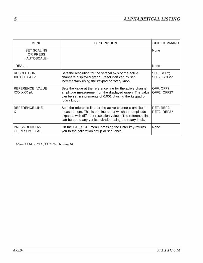
A-210 37XXXC OM
S ALPHABETICAL LISTING
MENU DESCRIPTION GPIB COMMAND
SET SCALINGOR PRESS
<AUTOSCALE>
None
–REAL– None
RESOLUTIONXX.XXX U/DIV
Sets the resolution for the vertical axis of the activechannel’s displayed graph. Resolution can by setincrementally using the keypad or rotary knob.
SCL; SCL?;SCL2; SCL2?
REFERENCE VALUEXXX.XXX pU
Sets the value at the reference line for the active channelamplitude measurement on the displayed graph. The valuecan be set in increments of 0.001 U using the keypad orrotary knob.
OFF; OFF?OFF2; OFF2?
REFERENCE LINEX
Sets the reference line for the active channel’s amplitudemeasurement. This is the line about which the amplitudeexpands with different resolution values. The reference linecan be set to any vertical division using the rotary knob.
REF; REF?;REF2; REF2?
PRESS <ENTER>TO RESUME CAL
On the CAL_SS10 menu, pressing the Enter key returnsyou to the calibration setup or sequence.
None
Menu SS10 or CAL_SS10, Set Scaling 10

37XXXC OM A-211
ALPHABETICAL LISTING S
MENU DESCRIPTION GPIB COMMAND
SET SCALINGOR PRESS
<AUTOSCALE>
None
–IMAGINARY– None
RESOLUTIONXX.XXX U/DIV
Sets the resolution for the vertical axis of the activechannel’s displayed graph. Resolution can by setincrementally using the keypad or rotary knob.
SCL; SCL?;SCL2; SCL2?
REFERENCE VALUEXXX.XXX pU
Sets the value at the reference line for the active channelamplitude measurement on the displayed graph. The valuecan be set in increments of 0.001 U using the keypad orrotary knob.
OFF; OFF?OFF2; OFF2?
REFERENCE LINEX
Sets the reference line for the active channel’s amplitudemeasurement. This is the line about which the amplitudeexpands with different resolution values. The reference linecan be set to any vertical division using the rotary knob.
REF; REF?;REF2; REF2?
PRESS <ENTER>TO RESUME CAL
On the CAL_SS11 menu, pressing the Enter key returnsyou to the calibration setup or sequence.
None
Menu SS11 or CAL_SS11, Set Scaling 11

A-212 37XXXC OM
S ALPHABETICAL LISTING
MENU DESCRIPTION GPIB COMMAND
SET SCALINGOR PRESS
<AUTOSCALE>
None
–REAL– None
RESOLUTIONXX.XXX U/DIV
Sets the resolution for the vertical axis of the activechannel’s displayed graph. Resolution can by setincrementally using the keypad or rotary knob.
SCL; SCL?;SCL2; SCL2?
REFERENCE VALUEXXX.XXX pU
Sets the value at the reference line for the active channelamplitude measurement on the displayed graph. The valuecan be set in increments of 0.001 U using the keypad orrotary knob.
OFF; OFF?OFF2; OFF2?
REFERENCE LINEX
Sets the reference line for the active channel’s amplitudemeasurement. This is the line about which the amplitudeexpands with different resolution values. The reference linecan be set to any vertical division using the rotary knob.
REF; REF?;REF2; REF2?
–IMAGINARY– None
RESOLUTIONXX.XX /DIV
Sets the resolution for the vertical axis of the activechannel’s displayed graph. Resolution can by setincrementally using the keypad or rotary knob.
SCL; SCL?;SCL2; SCL2?
REFERENCE VALUEXXX.XX
Sets the value by which the active channel’s phasemeasurement is offset on the phase graph. The offset canbe set in increments of 0.01 degrees using the keypad orrotary knob.
OFF; OFF?OFF2; OFF2?
REFERENCE LINEX
Sets the reference line for the active channel’s phasemeasurement on the phase graph. This is the line aboutwhich the phase expands with different resolution values.The reference line can be set to any vertical division usingthe rotary knob.
REF; REF?;REF2; REF2?
PRESS <ENTER>TO RESUME CAL
On the CAL_SS12 menu, pressing the Enter key returnsyou to the calibration setup or sequence.
None
Menu SS12 or CAL_SS12, Set Scaling 12
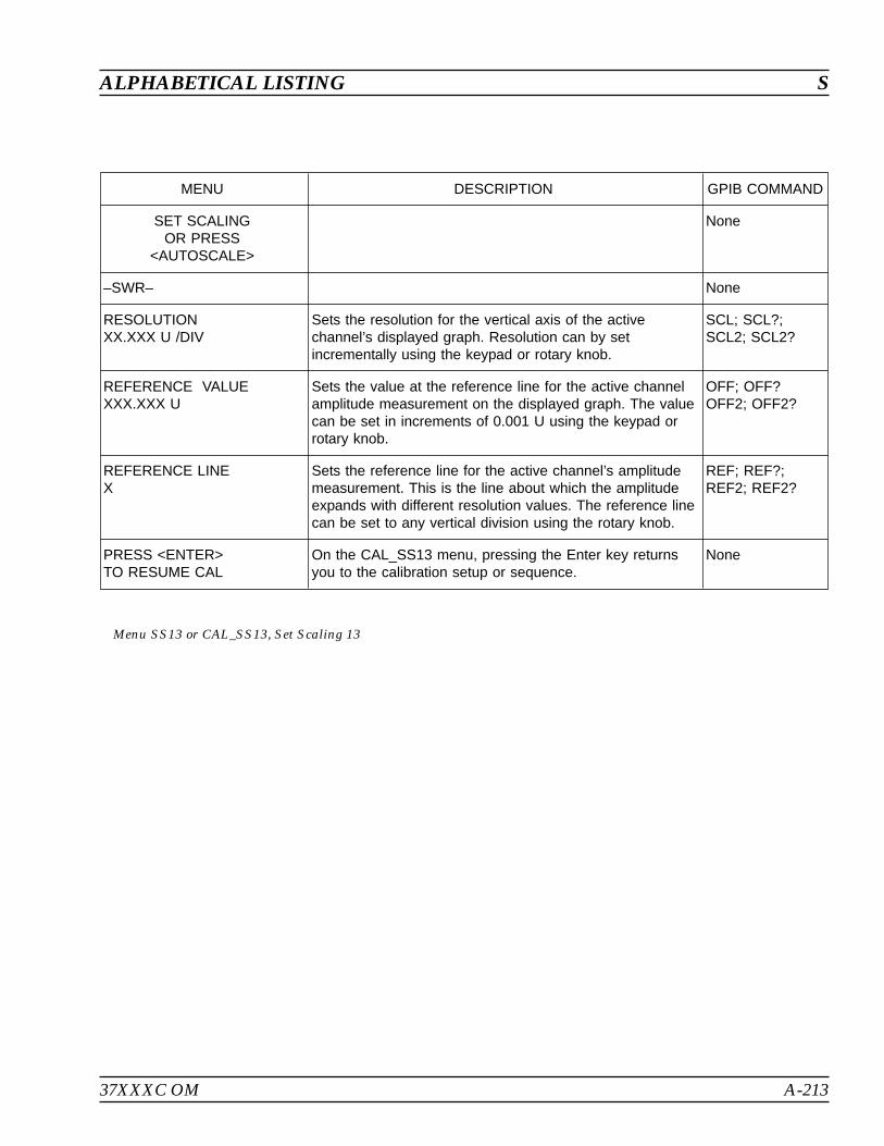
37XXXC OM A-213
ALPHABETICAL LISTING S
MENU DESCRIPTION GPIB COMMAND
SET SCALINGOR PRESS
<AUTOSCALE>
None
–SWR– None
RESOLUTIONXX.XXX U /DIV
Sets the resolution for the vertical axis of the activechannel’s displayed graph. Resolution can by setincrementally using the keypad or rotary knob.
SCL; SCL?;SCL2; SCL2?
REFERENCE VALUEXXX.XXX U
Sets the value at the reference line for the active channelamplitude measurement on the displayed graph. The valuecan be set in increments of 0.001 U using the keypad orrotary knob.
OFF; OFF?OFF2; OFF2?
REFERENCE LINEX
Sets the reference line for the active channel’s amplitudemeasurement. This is the line about which the amplitudeexpands with different resolution values. The reference linecan be set to any vertical division using the rotary knob.
REF; REF?;REF2; REF2?
PRESS <ENTER>TO RESUME CAL
On the CAL_SS13 menu, pressing the Enter key returnsyou to the calibration setup or sequence.
None
Menu SS13 or CAL_SS13, Set Scaling 13

A-214 37XXXC OM
S ALPHABETICAL LISTING
MENU DESCRIPTION GPIB COMMAND
SET SCALINGOR PRESS
<AUTOSCALE>
None
–POWER OUT– None
RESOLUTIONXX.XXX dB/DIV
Sets the resolution for the vertical axis of the activechannel’s displayed graph. Resolution can by setincrementally using the keypad or rotary knob.
SCL; SCL?;SCL2; SCL2?
REFERENCE VALUEXXX.XXX dBm
Sets the value at the reference line for the active channelamplitude measurement on the displayed graph.
OFF; OFF?OFF2; OFF2?
REFERENCE LINEX
Sets the reference line for the active channel’s amplitudemeasurement. This is the line about which the amplitudeexpands with different resolution values. The reference linecan be set to any vertical division using the rotary knob.
REF; REF?;REF2; REF2?
Menu SS14, Set Scaling 14
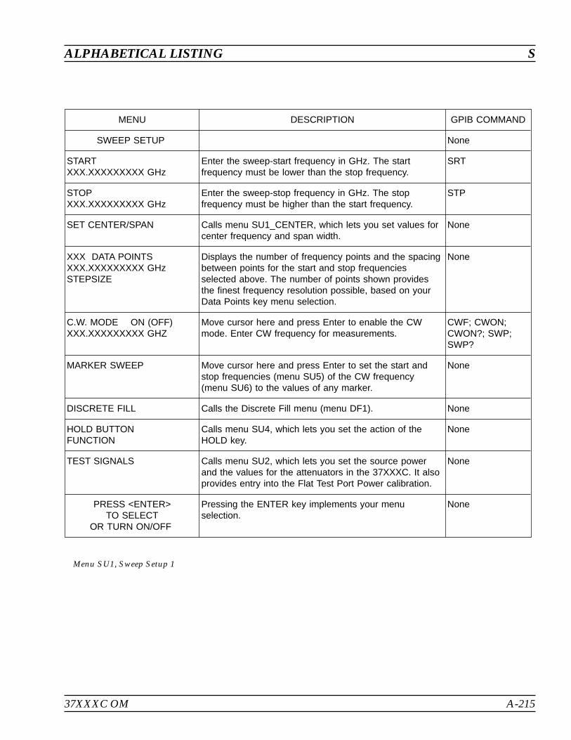
37XXXC OM A-215
ALPHABETICAL LISTING S
MENU DESCRIPTION GPIB COMMAND
SWEEP SETUP None
STARTXXX.XXXXXXXXX GHz
Enter the sweep-start frequency in GHz. The startfrequency must be lower than the stop frequency.
SRT
STOPXXX.XXXXXXXXX GHz
Enter the sweep-stop frequency in GHz. The stopfrequency must be higher than the start frequency.
STP
SET CENTER/SPAN Calls menu SU1_CENTER, which lets you set values forcenter frequency and span width.
None
XXX DATA POINTSXXX.XXXXXXXXX GHzSTEPSIZE
Displays the number of frequency points and the spacingbetween points for the start and stop frequenciesselected above. The number of points shown providesthe finest frequency resolution possible, based on yourData Points key menu selection.
None
C.W. MODE ON (OFF)XXX.XXXXXXXXX GHZ
Move cursor here and press Enter to enable the CWmode. Enter CW frequency for measurements.
CWF; CWON;CWON?; SWP;SWP?
MARKER SWEEP Move cursor here and press Enter to set the start andstop frequencies (menu SU5) of the CW frequency(menu SU6) to the values of any marker.
None
DISCRETE FILL Calls the Discrete Fill menu (menu DF1). None
HOLD BUTTONFUNCTION
Calls menu SU4, which lets you set the action of theHOLD key.
None
TEST SIGNALS Calls menu SU2, which lets you set the source powerand the values for the attenuators in the 37XXXC. It alsoprovides entry into the Flat Test Port Power calibration.
None
PRESS <ENTER>TO SELECT
OR TURN ON/OFF
Pressing the ENTER key implements your menuselection.
None
Menu SU1, Sweep Setup 1

A-216 37XXXC OM
S ALPHABETICAL LISTING
MENU DESCRIPTION GPIB COMMAND
SWEEP SETUP None
CENTERXXX.XXXXXXXXX GHz
Enter the center frequency in GHz. CNTR; CNTR?
SPANXXX.XXXXXXXXX GHz
Enter the span frequency in GHz. SPAN; SPAN?
SET START/STOP Calls menu SU1, which lets you set values for start andstop frequencies.
None
XXX DATA POINT(S)XXX.XXXXXXXXX GHzSTEPSIZE
Displays the number of frequency points and the spacingbetween points for the center and span frequenciesselected above. The number of points shown provides thefinest frequency resolution possible, based on your DataPoints key menu selection.
None
C.W. MODE ON (OFF)XXX.XXXXXXXXX GHZ
Move cursor here and press Enter to enable the CW mode.Enter CW frequency for measurements.
CWF; CWON;SWP; CWON?
MARKER SWEEP Move cursor here and press Enter to set the start and stopfrequencies (menu SU5) of the CW frequency (menu SU6)to the values of any marker.
None
DISCRETE FILL Calls the Discrete Fill menu (menu DF1). None
HOLD BUTTONFUNCTION
Calls menu SU4, which lets you set the action of the HOLDkey.
None
TEST SIGNALS Calls menu SU2, which lets you set the source power andthe values for the attenuators in the 37XXXC. It alsoprovides entry into the Flat Test Port Power calibration.
None
PRESS <ENTER>TO SELECT
OR TURN ON/OFF
Pressing the ENTER key implements your menu selection. None
Menu SU1_CENTER, Sweep Setup 1
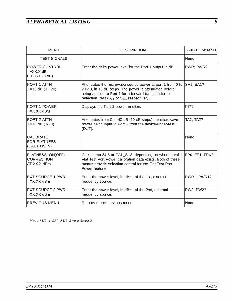
37XXXC OM A-217
ALPHABETICAL LISTING S
MENU DESCRIPTION GPIB COMMAND
TEST SIGNALS None
POWER CONTROL+XX.X dB
0 TO -15.0 dB)
Enter the delta-power level for the Port 1 output in dB. PWR; PWR?
PORT 1 ATTNXX10 dB (0 - 70)
Attenuates the microwave source power at port 1 from 0 to70 dB, in 10 dB steps. The power is attenuated beforebeing applied to Port 1 for a forward transmission orreflection test (S21 or S11, respectively).
SA1; SA1?
PORT 1 POWER-XX.XX dBM
Displays the Port 1 power, in dBm. PIP?
PORT 2 ATTNXX10 dB (0-X0)
Attenuates from 0 to 40 dB (10 dB steps) the microwavepower being input to Port 2 from the device-under-test(DUT).
TA2; TA2?
CALIBRATEFOR FLATNESS(CAL EXISTS)
None
FLATNESS ON(OFF)CORRECTIONAT XX.X dBm
Calls menu SU8 or CAL_SU8, depending on whether validFlat Test Port Power calibration data exists. Both of thesemenus provide selection control for the Flat Test PortPower feature.
FP0; FP1; FPX?
EXT SOURCE 1 PWR-XX.XX dBm
Enter the power level, in dBm, of the 1st, externalfrequency source.
PWR1; PWR1?
EXT SOURCE 2 PWR-XX.XX dBm
Enter the power level, in dBm, of the 2nd, externalfrequency source.
PW2; PW2?
PREVIOUS MENU Returns to the previous menu. None
Menu SU2 or CAL_SU2, Sweep Setup 2
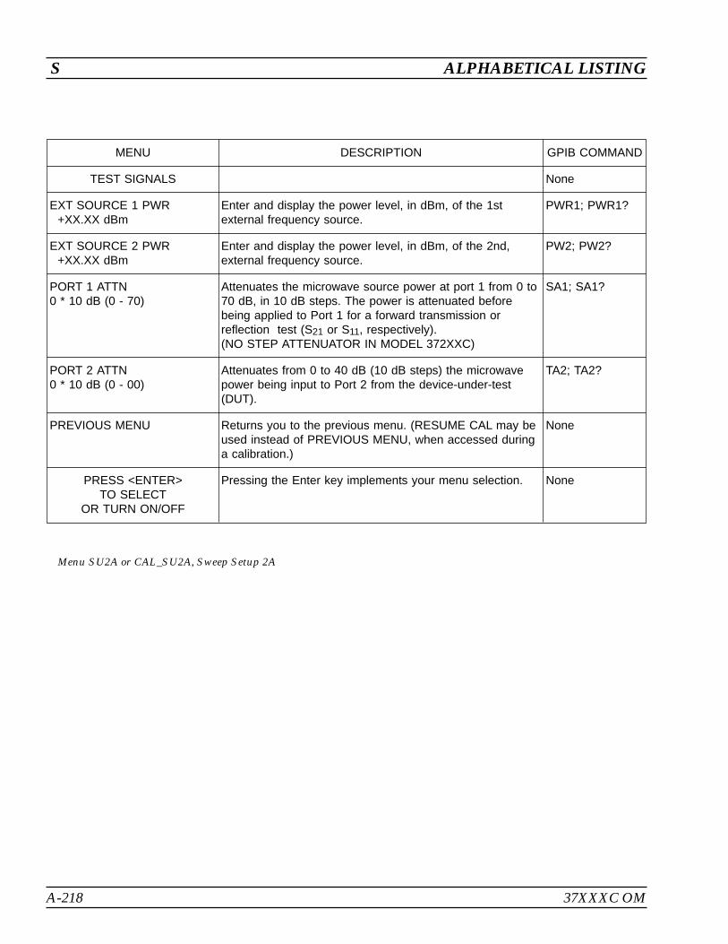
A-218 37XXXC OM
S ALPHABETICAL LISTING
MENU DESCRIPTION GPIB COMMAND
TEST SIGNALS None
EXT SOURCE 1 PWR+XX.XX dBm
Enter and display the power level, in dBm, of the 1stexternal frequency source.
PWR1; PWR1?
EXT SOURCE 2 PWR+XX.XX dBm
Enter and display the power level, in dBm, of the 2nd,external frequency source.
PW2; PW2?
PORT 1 ATTN0 * 10 dB (0 - 70)
Attenuates the microwave source power at port 1 from 0 to70 dB, in 10 dB steps. The power is attenuated beforebeing applied to Port 1 for a forward transmission orreflection test (S21 or S11, respectively).(NO STEP ATTENUATOR IN MODEL 372XXC)
SA1; SA1?
PORT 2 ATTN0 * 10 dB (0 - 00)
Attenuates from 0 to 40 dB (10 dB steps) the microwavepower being input to Port 2 from the device-under-test(DUT).
TA2; TA2?
PREVIOUS MENU Returns you to the previous menu. (RESUME CAL may beused instead of PREVIOUS MENU, when accessed duringa calibration.)
None
PRESS <ENTER>TO SELECT
OR TURN ON/OFF
Pressing the Enter key implements your menu selection. None
Menu SU2A or CAL_SU2A, Sweep Setup 2A
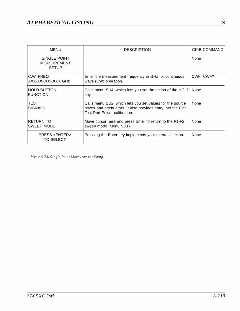
37XXXC OM A-219
ALPHABETICAL LISTING S
MENU DESCRIPTION GPIB COMMAND
SINGLE POINTMEASUREMENT
SETUP
None
C.W. FREQXXX.XXXXXXXXX GHz
Enter the measurement frequency in GHz for continuouswave (CW) operation.
CWF; CWF?
HOLD BUTTONFUNCTION
Calls menu SU4, which lets you set the action of the HOLDkey.
None
TESTSIGNALS
Calls menu SU2, which lets you set values for the sourcepower and attenuators. It also provides entry into the FlatTest Port Power calibration.
None
RETURN TOSWEEP MODE
Move cursor here and press Enter to return to the F1-F2sweep mode (Menu SU1).
None
PRESS <ENTER>TO SELECT
Pressing the Enter key implements your menu selection. None
Menu SU3, Single-Point Measurement Setup
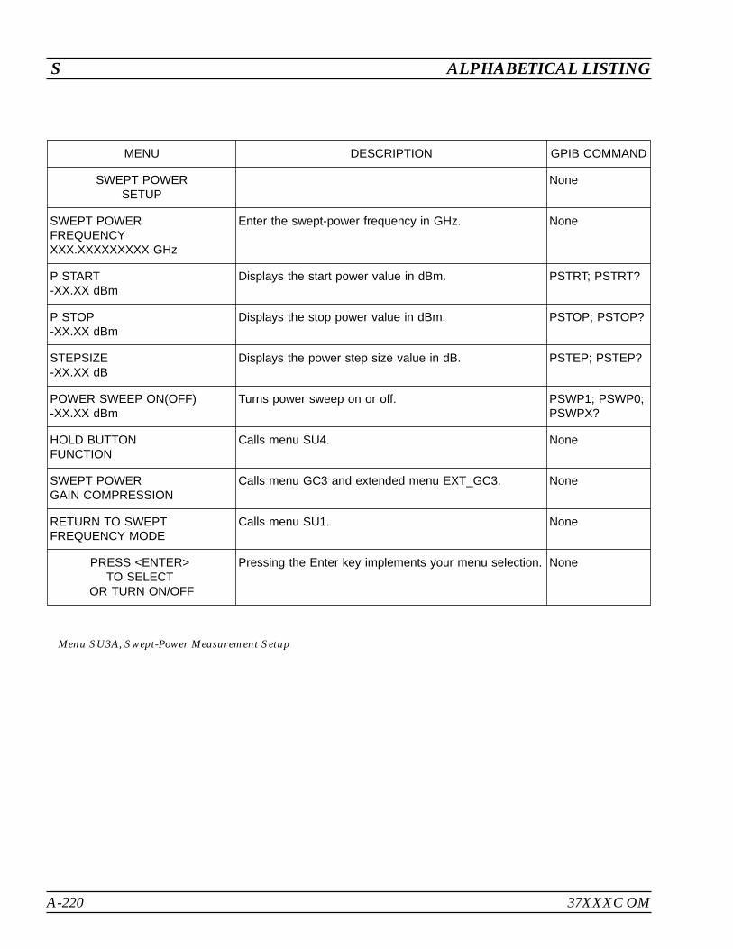
A-220 37XXXC OM
S ALPHABETICAL LISTING
MENU DESCRIPTION GPIB COMMAND
SWEPT POWERSETUP
None
SWEPT POWERFREQUENCYXXX.XXXXXXXXX GHz
Enter the swept-power frequency in GHz. None
P START-XX.XX dBm
Displays the start power value in dBm. PSTRT; PSTRT?
P STOP-XX.XX dBm
Displays the stop power value in dBm. PSTOP; PSTOP?
STEPSIZE-XX.XX dB
Displays the power step size value in dB. PSTEP; PSTEP?
POWER SWEEP ON(OFF)-XX.XX dBm
Turns power sweep on or off. PSWP1; PSWP0;PSWPX?
HOLD BUTTONFUNCTION
Calls menu SU4. None
SWEPT POWERGAIN COMPRESSION
Calls menu GC3 and extended menu EXT_GC3. None
RETURN TO SWEPTFREQUENCY MODE
Calls menu SU1. None
PRESS <ENTER>TO SELECT
OR TURN ON/OFF
Pressing the Enter key implements your menu selection. None
Menu SU3A, Swept-Power Measurement Setup

37XXXC OM A-221
ALPHABETICAL LISTING S
MENU DESCRIPTION GPIB COMMAND
SELECTFUNCTION FORHOLD BUTTON
None
HOLD/CONTINUE Causes the hold key (button) to stop and start the sweep. HLD/CTN; HLD?
HOLD/RESTART Causes the hold key to stop and restart the sweep. None
SINGLE SWEEPAND HOLD
Causes the hold key to trigger a single sweep and holdwhen finished. (Two sweeps, one from Port 1 to 2 andanother from Port 2 to 1, are accomplished for a 12-Termmeasurement.)
HLD; TRS
BIAS/RF HOLDCONDITIONS
BIAS ON (OFF) Select bias to be on or off (test sets having bias input only)while system is in hold.
BH1; BH0; BHX?
RF ON (OFF) Selects RF to be on or off while system is in hold. RH1; RH0; RHX?
DUT/AUT ON (OFF)PROTECTIONDEFAULT RESETTURNS ON HOLDWITH BIAS/RFTURNED OFF
When on, a default reset places the system in hold with RFand bias turned off. This choice is initialized to OFF whenthe software version changes or after a Default Programkey press, so that the system comes up in the sweepmode.
PRESS <ENTER>TO SELECT
Pressing the Enter key implements your menu selection. None
Menu SU4, Select Function for Hold Button
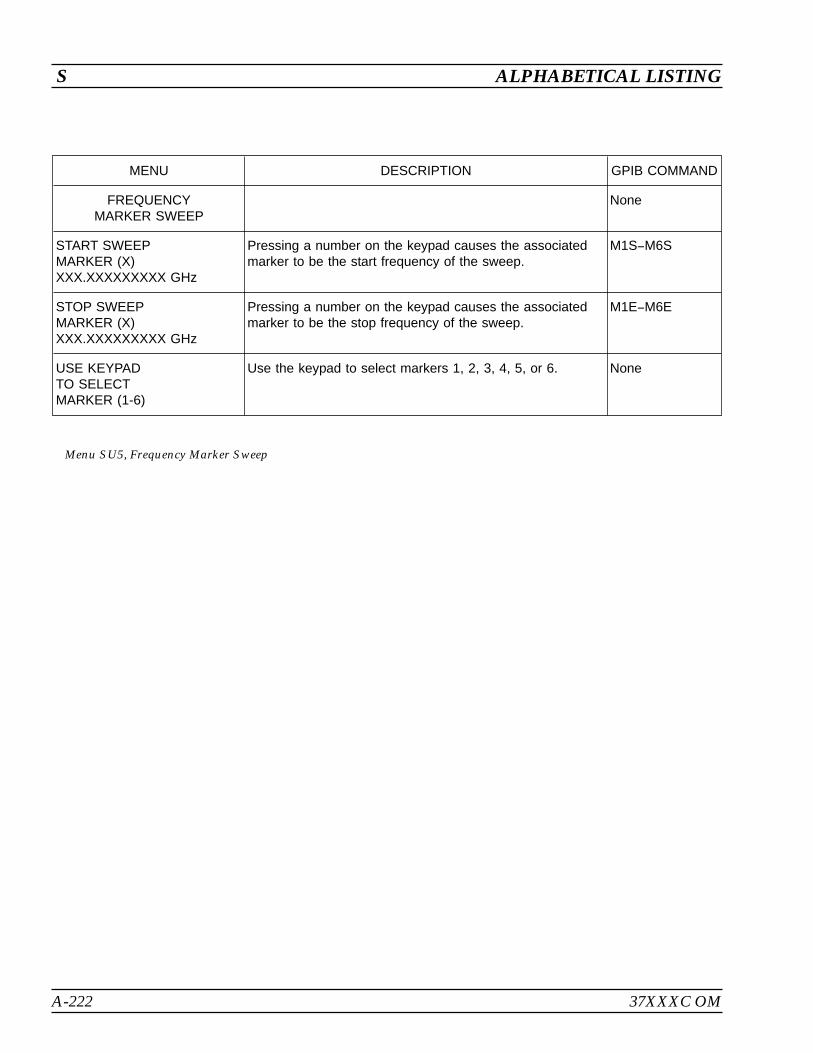
A-222 37XXXC OM
S ALPHABETICAL LISTING
MENU DESCRIPTION GPIB COMMAND
FREQUENCYMARKER SWEEP
None
START SWEEPMARKER (X)XXX.XXXXXXXXX GHz
Pressing a number on the keypad causes the associatedmarker to be the start frequency of the sweep.
M1SM6S
STOP SWEEPMARKER (X)XXX.XXXXXXXXX GHz
Pressing a number on the keypad causes the associatedmarker to be the stop frequency of the sweep.
M1EM6E
USE KEYPADTO SELECTMARKER (1-6)
Use the keypad to select markers 1, 2, 3, 4, 5, or 6. None
Menu SU5, Frequency Marker Sweep
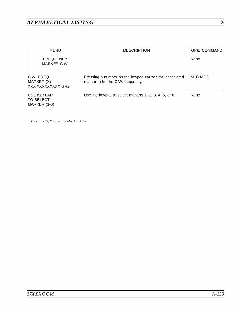
37XXXC OM A-223
ALPHABETICAL LISTING S
MENU DESCRIPTION GPIB COMMAND
FREQUENCYMARKER C.W.
None
C.W FREQMARKER (X)XXX.XXXXXXXXX GHz
Pressing a number on the keypad causes the associatedmarker to be the C.W. frequency.
M1C-M6C
USE KEYPADTO SELECTMARKER (1-6)
Use the keypad to select markers 1, 2, 3, 4, 5, or 6. None
Menu SU6, Frequency Marker C.W.

A-224 37XXXC OM
S ALPHABETICAL LISTING
MENU DESCRIPTION GPIB COMMAND
CALIBRATE FORFLAT PORT POWER
None
FORWARDDIRECTION ONLY
None
XXX POINTSMEASURE 1 PWRPOINT EVERY
XX POINT(S)
Displays the number of power points (0 – 50) to be skippedduring the power sweep. The points not measured areinterpolated to provide a flat sweep.
PTS; PTS?
POWER TARGET-XXX.X dBm
Lets users set a flat output-power value (power target). TheVNA defaults to Port 1 power.
PTP; PTP?
START FLATPOWER CALIBRATION
Begins the calibration. If calibration is successful, you arereturned to menu SU8. If the calibration unsuccessful dueto a fatal error (Source or power meter inoperable or notconnected), this menus remains displayed. At any time,you can abort the calibration by pressing the DEFAULTPROGRAM or CLEAR/RET LOC keys. All other keys arelocked out.
SFC
PRESS <ENTER>TO SELECT
TURN KNOB TOCHANGE NUMBER
OF POINTS
Pressing the Enter key implements your menu selection orturns the function on/off.
None
Menu SU8 or CAL_SU8, Calibrate For Flat Test Port Power

37XXXC OM A-225
ALPHABETICAL LISTING S
FLAT POWERCALIBRATION ADJUSTS THE SOURCE
OUTPUTPOWERAT EACH MEASUREMENTPOINT ACROSS
A FREQUENCYSPAN TO PROVIDE A CONSTANTPOWER
LEVEL AT THE TEST PORT (FORWARDDIRECTION ONLY).
1. PRESET, ZERO, AND CALIBRATE THE POWERMETER.
2. CREATE AND ACTIVATE THE POWERMETER'S CAL
FACTORLIST FOR THE POWERSENSORBEING USED.
3. CONNECTTHE POWERMETERTO THE DEDICATED GPIB
INTERFACE AND THE POWERSENSORTO THE TEST PORT.
4. SELECT <START FLAT POWERCALIBRATION>.
- FLAT POWERCALIBRATION -
- INSTRUCTIONS -
000.0 %
Menu EXT_SU8 Flat Power Calibration Instructions
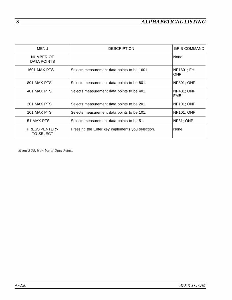
A-226 37XXXC OM
S ALPHABETICAL LISTING
MENU DESCRIPTION GPIB COMMAND
NUMBER OFDATA POINTS
None
1601 MAX PTS Selects measurement data points to be 1601. NP1601; FHI;ONP
801 MAX PTS Selects measurement data points to be 801. NP801; ONP
401 MAX PTS Selects measurement data points to be 401. NP401; ONP;FME
201 MAX PTS Selects measurement data points to be 201. NP101; ONP
101 MAX PTS Selects measurement data points to be 101. NP101; ONP
51 MAX PTS Selects measurement data points to be 51. NP51; ONP
PRESS <ENTER>TO SELECT
Pressing the Enter key implements you selection. None
Menu SU9, Number of Data Points

37XXXC OM A-227
ALPHABETICAL LISTING S
MENU DESCRIPTION GPIB COMMAND
NUMBER OFDATA POINTS
None
POINTS DRAWNIN C.W.
XXXX POINT(S)
Displays the number of data point, when in the CW mode.This number can be between 1 and 1601.
CWP; CWP?
Menu SU9A, Number of Data Points 2
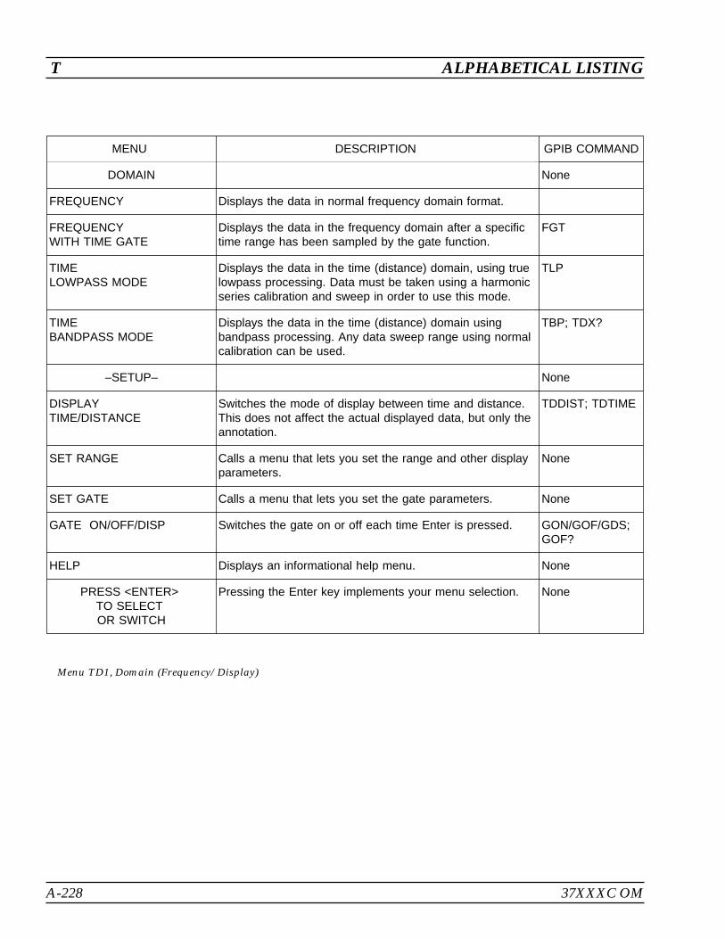
A-228 37XXXC OM
T ALPHABETICAL LISTING
MENU DESCRIPTION GPIB COMMAND
DOMAIN None
FREQUENCY Displays the data in normal frequency domain format.
FREQUENCYWITH TIME GATE
Displays the data in the frequency domain after a specifictime range has been sampled by the gate function.
FGT
TIMELOWPASS MODE
Displays the data in the time (distance) domain, using truelowpass processing. Data must be taken using a harmonicseries calibration and sweep in order to use this mode.
TLP
TIMEBANDPASS MODE
Displays the data in the time (distance) domain usingbandpass processing. Any data sweep range using normalcalibration can be used.
TBP; TDX?
–SETUP– None
DISPLAYTIME/DISTANCE
Switches the mode of display between time and distance.This does not affect the actual displayed data, but only theannotation.
TDDIST; TDTIME
SET RANGE Calls a menu that lets you set the range and other displayparameters.
None
SET GATE Calls a menu that lets you set the gate parameters. None
GATE ON/OFF/DISP Switches the gate on or off each time Enter is pressed. GON/GOF/GDS;GOF?
HELP Displays an informational help menu. None
PRESS <ENTER>TO SELECTOR SWITCH
Pressing the Enter key implements your menu selection. None
Menu TD1, Domain (Frequency/Display)
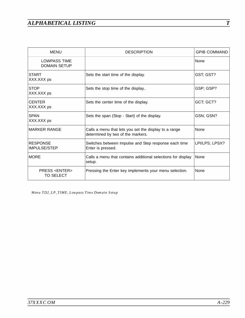
37XXXC OM A-229
ALPHABETICAL LISTING T
MENU DESCRIPTION GPIB COMMAND
LOWPASS TIMEDOMAIN SETUP
None
STARTXXX.XXX ps
Sets the start time of the display. GST; GST?
STOPXXX.XXX ps
Sets the stop time of the display.. GSP; GSP?
CENTERXXX.XXX ps
Sets the center time of the display. GCT; GCT?
SPANXXX.XXX ps
Sets the span (Stop - Start) of the display. GSN; GSN?
MARKER RANGE Calls a menu that lets you set the display to a rangedetermined by two of the markers.
None
RESPONSEIMPULSE/STEP
Switches between Impulse and Step response each timeEnter is pressed.
LPI/LPS; LPSX?
MORE Calls a menu that contains additional selections for displaysetup.
None
PRESS <ENTER>TO SELECT
Pressing the Enter key implements your menu selection. None
Menu TD2_LP_TIME, Lowpass Time Domain Setup
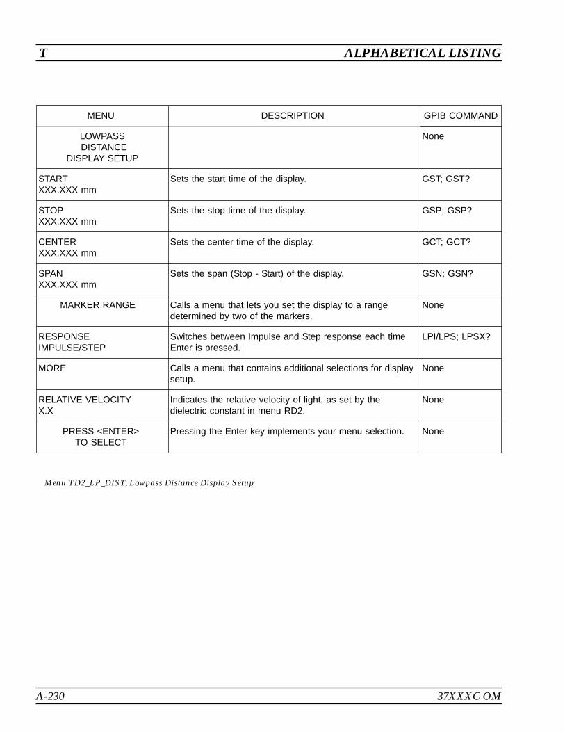
A-230 37XXXC OM
T ALPHABETICAL LISTING
MENU DESCRIPTION GPIB COMMAND
LOWPASSDISTANCE
DISPLAY SETUP
None
STARTXXX.XXX mm
Sets the start time of the display. GST; GST?
STOPXXX.XXX mm
Sets the stop time of the display. GSP; GSP?
CENTERXXX.XXX mm
Sets the center time of the display. GCT; GCT?
SPANXXX.XXX mm
Sets the span (Stop - Start) of the display. GSN; GSN?
MARKER RANGE Calls a menu that lets you set the display to a rangedetermined by two of the markers.
None
RESPONSEIMPULSE/STEP
Switches between Impulse and Step response each timeEnter is pressed.
LPI/LPS; LPSX?
MORE Calls a menu that contains additional selections for displaysetup.
None
RELATIVE VELOCITYX.X
Indicates the relative velocity of light, as set by thedielectric constant in menu RD2.
None
PRESS <ENTER>TO SELECT
Pressing the Enter key implements your menu selection. None
Menu TD2_LP_DIST, Lowpass Distance Display Setup

37XXXC OM A-231
ALPHABETICAL LISTING T
MENU DESCRIPTION GPIB COMMAND
BANDPASS TIMEDOMAIN SETUP
None
STARTXXX.XXX ps
Sets the start time of the display. ZST; ZST?
STOPXXX.XXX ps
Sets the stop time of the display. ZSP; ZSP?
CENTERXXX.XXX ps
Sets the center time of the display. ZCT; ZCT?
SPANXXX.XXX ps
Sets the span (Stop - Start) of the display. ZSN; ZSN?
MARKER RANGE Calls a menu that lets you set the display to a rangedetermined by two of the markers.
None
PHASOR ON/OFFIMPULSE
Switches Phasor Impulse processing on or off each timeEnter is pressed.
TDPI1; TDPI0;TDPIX?
HELP – PHASORIMPULSE
Displays an informational help menu. None
MORE Calls a menu that contains additional selections for displaysetup.
None
PRESS <ENTER>TO SELECT
OR TURN ON/OFF
Pressing the Enter key implements your menu selection. None
Menu TD2_BP_TIME, Bandpass Time Domain Setup

A-232 37XXXC OM
T ALPHABETICAL LISTING
MENU DESCRIPTION GPIB COMMAND
BANDPASS DISTANCEDISPLAY SETUP
None
STARTXXX.XXX mm
Sets the start time of the display. ZST; ZST?
STOPXXX.XXX mm
Sets the stop time of the display. ZSP; ZSP?
CENTERXXX.XXX mm
Sets the center time of the display. ZCT; ZCT?
SPANXXX.XXX mm
Sets the span (Stop - Start) of the display. ZSN; ZSN?
MARKER RANGE Calls a menu that lets you set the display to a rangedetermined by two of the markers.
None
PHASOR ON/OFFIMPULSE
Switches Phasor Impulse processing on or off each timeEnter is pressed.
TDPI1; TDPI0;TDPIX?
HELP – PHASORIMPULSE
Displays an informational help menu. None
MORE Calls a menu that contains additional selections for displaysetup.
None
RELATIVE VELOCITYX.X
Indicates the relative velocity of light, as set by thedielectric constant in menu RD2.
None
PRESS <ENTER>TO SELECT
OR TURN ON/OFF
Pressing the Enter key implements your menu selection. None
Menu TD2_BP_DIST, Bandpass Distance Display Setup
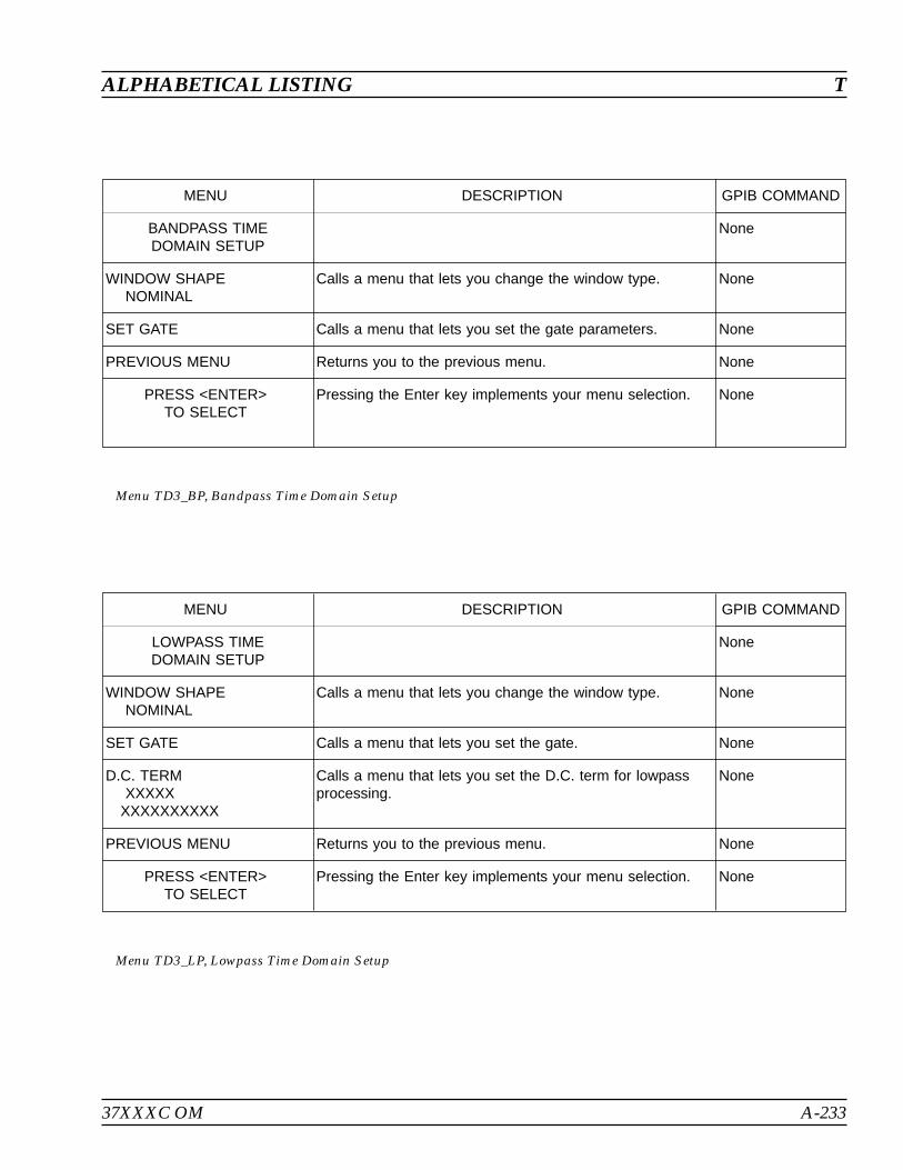
37XXXC OM A-233
ALPHABETICAL LISTING T
MENU DESCRIPTION GPIB COMMAND
BANDPASS TIMEDOMAIN SETUP
None
WINDOW SHAPENOMINAL
Calls a menu that lets you change the window type. None
SET GATE Calls a menu that lets you set the gate parameters. None
PREVIOUS MENU Returns you to the previous menu. None
PRESS <ENTER>TO SELECT
Pressing the Enter key implements your menu selection. None
Menu TD3_BP, Bandpass Time Domain Setup
MENU DESCRIPTION GPIB COMMAND
LOWPASS TIMEDOMAIN SETUP
None
WINDOW SHAPENOMINAL
Calls a menu that lets you change the window type. None
SET GATE Calls a menu that lets you set the gate. None
D.C. TERMXXXXX
XXXXXXXXXX
Calls a menu that lets you set the D.C. term for lowpassprocessing.
None
PREVIOUS MENU Returns you to the previous menu. None
PRESS <ENTER>TO SELECT
Pressing the Enter key implements your menu selection. None
Menu TD3_LP, Lowpass Time Domain Setup
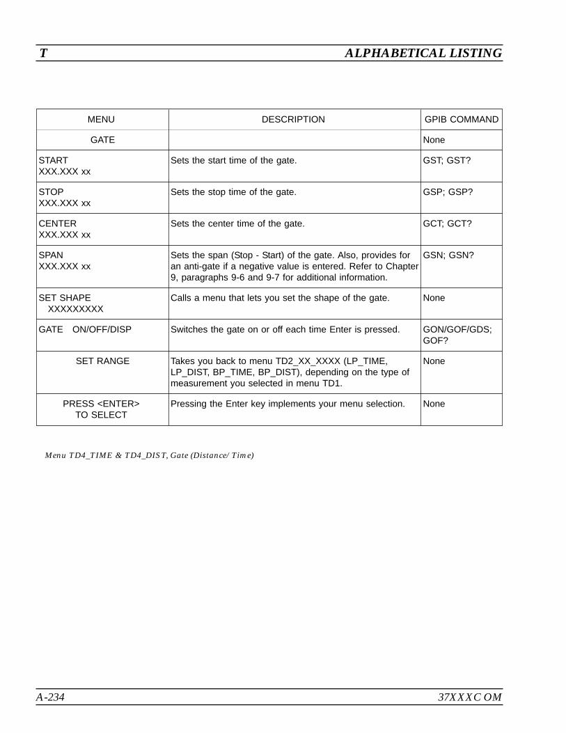
A-234 37XXXC OM
T ALPHABETICAL LISTING
MENU DESCRIPTION GPIB COMMAND
GATE None
STARTXXX.XXX xx
Sets the start time of the gate. GST; GST?
STOPXXX.XXX xx
Sets the stop time of the gate. GSP; GSP?
CENTERXXX.XXX xx
Sets the center time of the gate. GCT; GCT?
SPANXXX.XXX xx
Sets the span (Stop - Start) of the gate. Also, provides foran anti-gate if a negative value is entered. Refer to Chapter9, paragraphs 9-6 and 9-7 for additional information.
GSN; GSN?
SET SHAPEXXXXXXXXX
Calls a menu that lets you set the shape of the gate. None
GATE ON/OFF/DISP Switches the gate on or off each time Enter is pressed. GON/GOF/GDS;GOF?
SET RANGE Takes you back to menu TD2_XX_XXXX (LP_TIME,LP_DIST, BP_TIME, BP_DIST), depending on the type ofmeasurement you selected in menu TD1.
None
PRESS <ENTER>TO SELECT
Pressing the Enter key implements your menu selection. None
Menu TD4_TIME & TD4_DIST, Gate (Distance/Time)
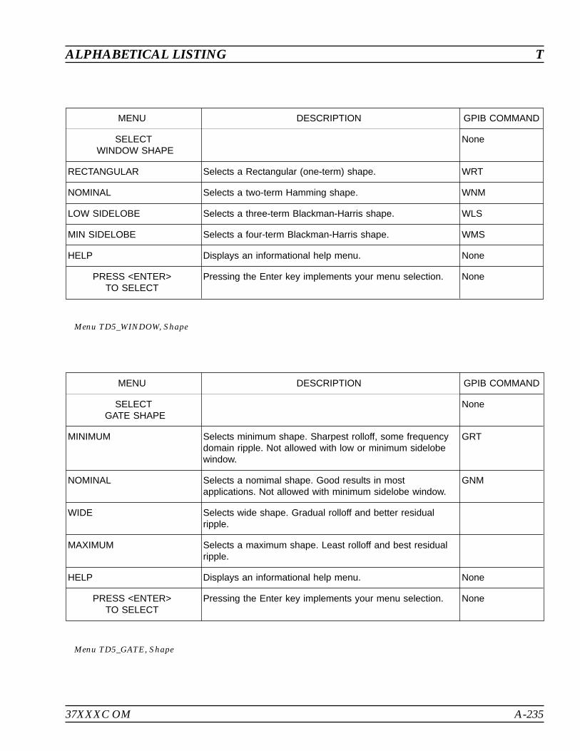
37XXXC OM A-235
ALPHABETICAL LISTING T
MENU DESCRIPTION GPIB COMMAND
SELECTWINDOW SHAPE
None
RECTANGULAR Selects a Rectangular (one-term) shape. WRT
NOMINAL Selects a two-term Hamming shape. WNM
LOW SIDELOBE Selects a three-term Blackman-Harris shape. WLS
MIN SIDELOBE Selects a four-term Blackman-Harris shape. WMS
HELP Displays an informational help menu. None
PRESS <ENTER>TO SELECT
Pressing the Enter key implements your menu selection. None
Menu TD5_WINDOW, Shape
MENU DESCRIPTION GPIB COMMAND
SELECTGATE SHAPE
None
MINIMUM Selects minimum shape. Sharpest rolloff, some frequencydomain ripple. Not allowed with low or minimum sidelobewindow.
GRT
NOMINAL Selects a nomimal shape. Good results in mostapplications. Not allowed with minimum sidelobe window.
GNM
WIDE Selects wide shape. Gradual rolloff and better residualripple.
MAXIMUM Selects a maximum shape. Least rolloff and best residualripple.
HELP Displays an informational help menu. None
PRESS <ENTER>TO SELECT
Pressing the Enter key implements your menu selection. None
Menu TD5_GATE, Shape

A-236 37XXXC OM
T ALPHABETICAL LISTING
MENU DESCRIPTION GPIB COMMAND
SET D.C. TERM FORLOWPASS PROCESSING
Since it is impossible to measure the true D.C. termrequired for lowpass processing, a value must beestimated. This menu allows a choice between five differentselections for this value.
None
AUTOEXTRAPOLATE
Sets the D.C. term to a value determined by extrapolatingthe data points near the zero frequency.
DCA; DCX?
LINEIMPEDANCE
Sets the D.C. term to the characteristic impedance of thetransmission medium (Z0).
DCZ
OPEN Sets the D.C. term to correspond to an open circuit. DCO
SHORT Sets the D.C. term to correspond to a short circuit. DCS
OTHERXXX.XXX(REFLECTIONCOEFFICIENT
X.XXX pU)
Sets the D.C. term to the value entered. DCV; DCV?
DCX?
PREVIOUS MENU Returns you to the previous menu. None
PRESS <ENTER>TO SELECT
Pressing the Enter key implements your menu selection. None
Menu TD6, Set D.C. Term for Low Pass Processing
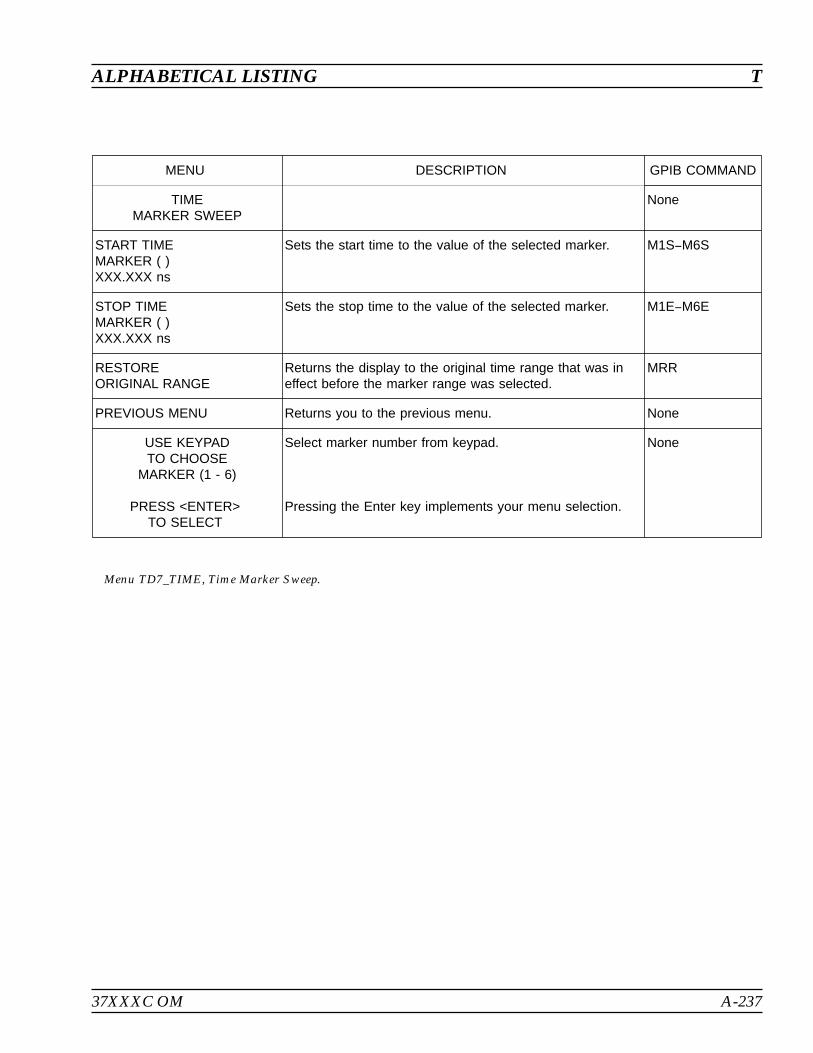
37XXXC OM A-237
ALPHABETICAL LISTING T
MENU DESCRIPTION GPIB COMMAND
TIMEMARKER SWEEP
None
START TIMEMARKER ( )XXX.XXX ns
Sets the start time to the value of the selected marker. M1SM6S
STOP TIMEMARKER ( )XXX.XXX ns
Sets the stop time to the value of the selected marker. M1EM6E
RESTOREORIGINAL RANGE
Returns the display to the original time range that was ineffect before the marker range was selected.
MRR
PREVIOUS MENU Returns you to the previous menu. None
USE KEYPADTO CHOOSE
MARKER (1 - 6)
PRESS <ENTER>TO SELECT
Select marker number from keypad.
Pressing the Enter key implements your menu selection.
None
Menu TD7_TIME, Time Marker Sweep.
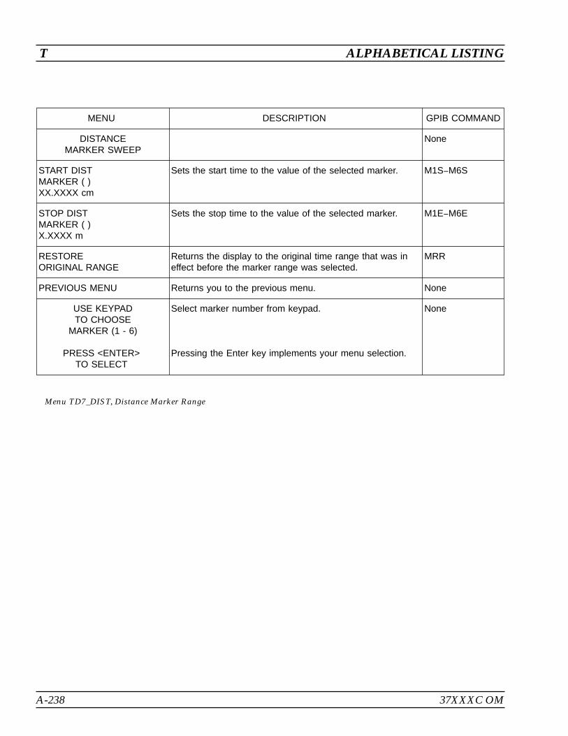
A-238 37XXXC OM
T ALPHABETICAL LISTING
MENU DESCRIPTION GPIB COMMAND
DISTANCEMARKER SWEEP
None
START DISTMARKER ( )XX.XXXX cm
Sets the start time to the value of the selected marker. M1SM6S
STOP DISTMARKER ( )X.XXXX m
Sets the stop time to the value of the selected marker. M1EM6E
RESTOREORIGINAL RANGE
Returns the display to the original time range that was ineffect before the marker range was selected.
MRR
PREVIOUS MENU Returns you to the previous menu. None
USE KEYPADTO CHOOSE
MARKER (1 - 6)
PRESS <ENTER>TO SELECT
Select marker number from keypad.
Pressing the Enter key implements your menu selection.
None
Menu TD7_DIST, Distance Marker Range
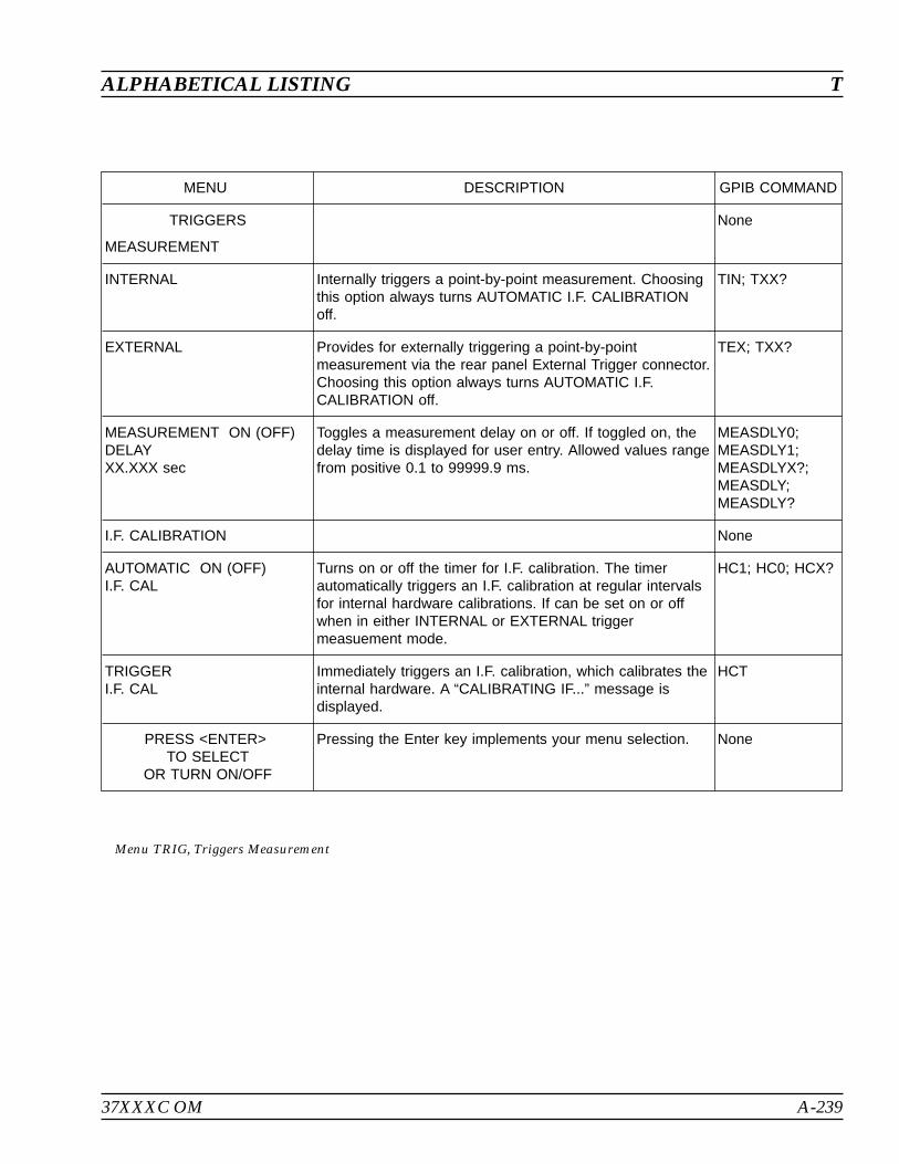
37XXXC OM A-239
ALPHABETICAL LISTING T
MENU DESCRIPTION GPIB COMMAND
TRIGGERS
MEASUREMENT
None
INTERNAL Internally triggers a point-by-point measurement. Choosingthis option always turns AUTOMATIC I.F. CALIBRATIONoff.
TIN; TXX?
EXTERNAL Provides for externally triggering a point-by-pointmeasurement via the rear panel External Trigger connector.Choosing this option always turns AUTOMATIC I.F.CALIBRATION off.
TEX; TXX?
MEASUREMENT ON (OFF)DELAYXX.XXX sec
Toggles a measurement delay on or off. If toggled on, thedelay time is displayed for user entry. Allowed values rangefrom positive 0.1 to 99999.9 ms.
MEASDLY0;MEASDLY1;MEASDLYX?;MEASDLY;MEASDLY?
I.F. CALIBRATION None
AUTOMATIC ON (OFF)I.F. CAL
Turns on or off the timer for I.F. calibration. The timerautomatically triggers an I.F. calibration at regular intervalsfor internal hardware calibrations. If can be set on or offwhen in either INTERNAL or EXTERNAL triggermeasuement mode.
HC1; HC0; HCX?
TRIGGERI.F. CAL
Immediately triggers an I.F. calibration, which calibrates theinternal hardware. A “CALIBRATING IF...” message isdisplayed.
HCT
PRESS <ENTER>TO SELECT
OR TURN ON/OFF
Pressing the Enter key implements your menu selection. None
Menu TRIG, Triggers Measurement
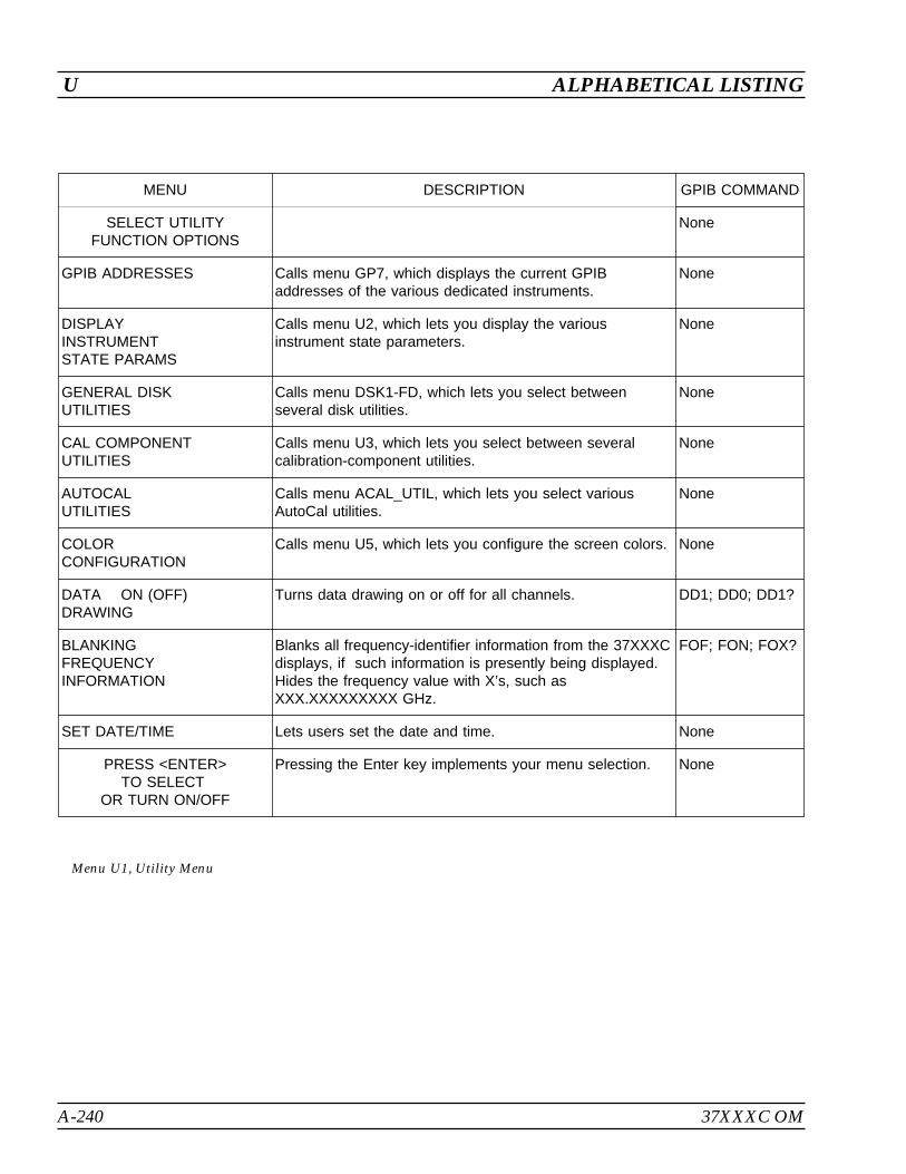
A-240 37XXXC OM
U ALPHABETICAL LISTING
MENU DESCRIPTION GPIB COMMAND
SELECT UTILITYFUNCTION OPTIONS
None
GPIB ADDRESSES Calls menu GP7, which displays the current GPIBaddresses of the various dedicated instruments.
None
DISPLAYINSTRUMENTSTATE PARAMS
Calls menu U2, which lets you display the variousinstrument state parameters.
None
GENERAL DISKUTILITIES
Calls menu DSK1-FD, which lets you select betweenseveral disk utilities.
None
CAL COMPONENTUTILITIES
Calls menu U3, which lets you select between severalcalibration-component utilities.
None
AUTOCALUTILITIES
Calls menu ACAL_UTIL, which lets you select variousAutoCal utilities.
None
COLORCONFIGURATION
Calls menu U5, which lets you configure the screen colors. None
DATA ON (OFF)DRAWING
Turns data drawing on or off for all channels. DD1; DD0; DD1?
BLANKINGFREQUENCYINFORMATION
Blanks all frequency-identifier information from the 37XXXCdisplays, if such information is presently being displayed.Hides the frequency value with X’s, such asXXX.XXXXXXXXX GHz.
FOF; FON; FOX?
SET DATE/TIME Lets users set the date and time. None
PRESS <ENTER>TO SELECT
OR TURN ON/OFF
Pressing the Enter key implements your menu selection. None
Menu U1, Utility Menu
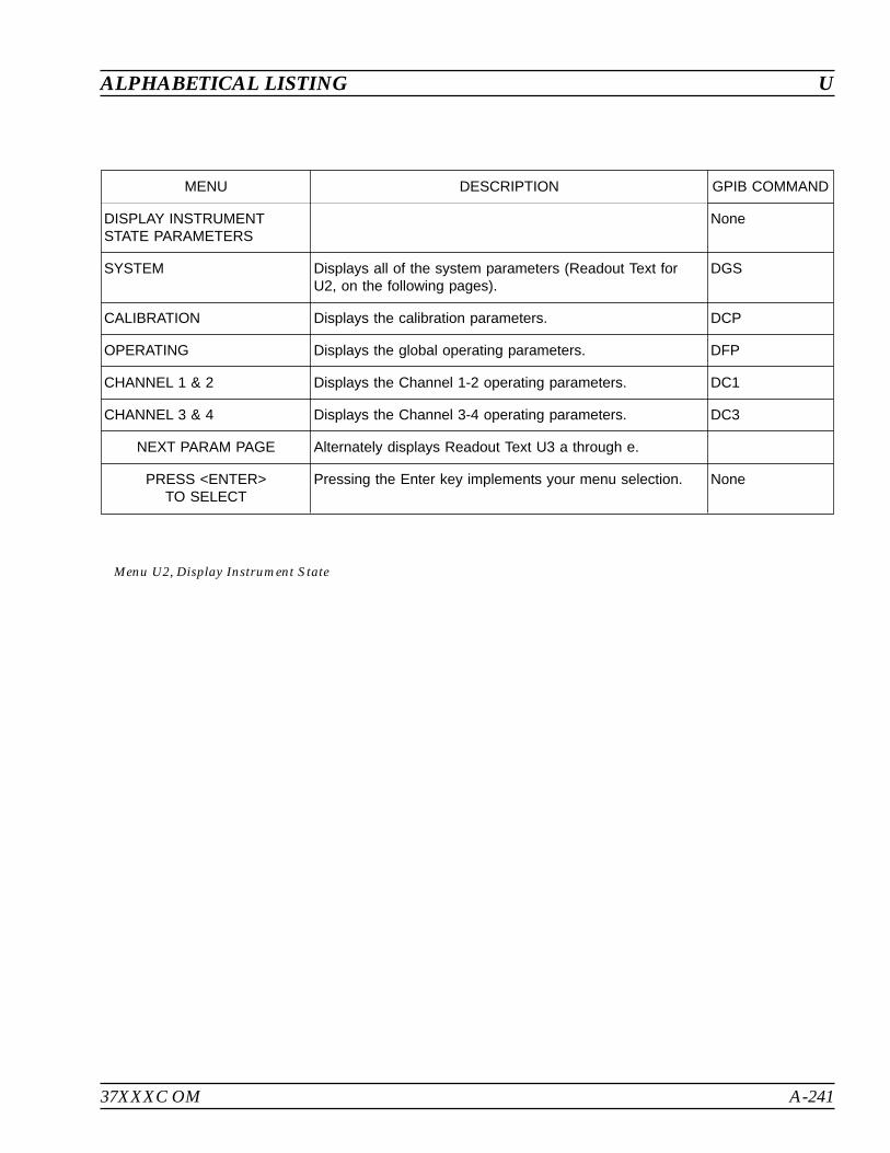
37XXXC OM A-241
ALPHABETICAL LISTING U
MENU DESCRIPTION GPIB COMMAND
DISPLAY INSTRUMENTSTATE PARAMETERS
None
SYSTEM Displays all of the system parameters (Readout Text forU2, on the following pages).
DGS
CALIBRATION Displays the calibration parameters. DCP
OPERATING Displays the global operating parameters. DFP
CHANNEL 1 & 2 Displays the Channel 1-2 operating parameters. DC1
CHANNEL 3 & 4 Displays the Channel 3-4 operating parameters. DC3
NEXT PARAM PAGE Alternately displays Readout Text U3 a through e.
PRESS <ENTER>TO SELECT
Pressing the Enter key implements your menu selection. None
Menu U2, Display Instrument State
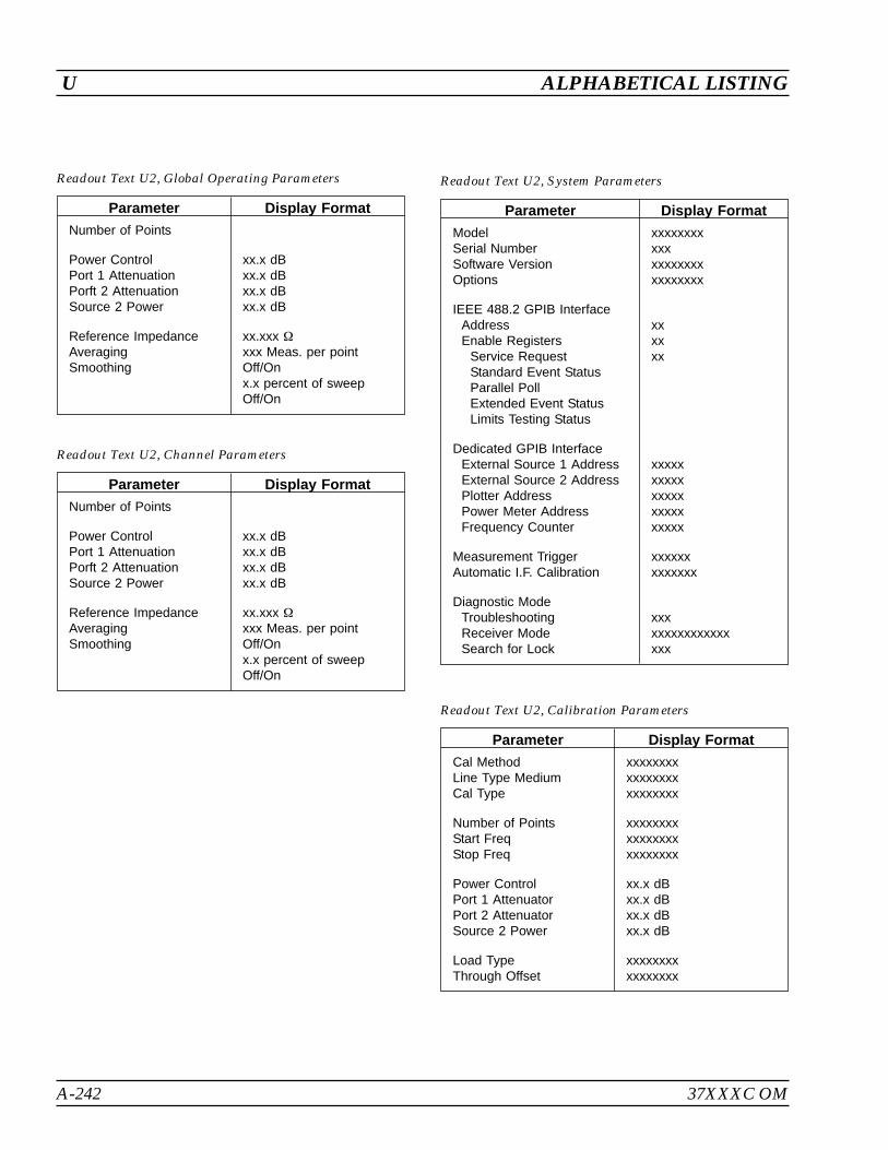
A-242 37XXXC OM
U ALPHABETICAL LISTING
Parameter Display Format
Number of Points
Power ControlPort 1 AttenuationPorft 2 AttenuationSource 2 Power
xx.x dBxx.x dBxx.x dBxx.x dB
Reference ImpedanceAveragingSmoothing
xx.xxx
xxx Meas. per pointOff/Onx.x percent of sweepOff/On
Readout Text U2, Global Operating Parameters
Parameter Display Format
ModelSerial NumberSoftware VersionOptions
xxxxxxxxxxxxxxxxxxxxxxxxxxx
IEEE 488.2 GPIB InterfaceAddressEnable Registers
Service RequestStandard Event StatusParallel PollExtended Event StatusLimits Testing Status
xxxxxx
Dedicated GPIB InterfaceExternal Source 1 AddressExternal Source 2 AddressPlotter AddressPower Meter AddressFrequency Counter
xxxxxxxxxxxxxxxxxxxxxxxxx
Measurement TriggerAutomatic I.F. Calibration
xxxxxxxxxxxxx
Diagnostic ModeTroubleshootingReceiver ModeSearch for Lock
xxxxxxxxxxxxxxxxxx
Readout Text U2, System Parameters
Parameter Display Format
Number of Points
Power ControlPort 1 AttenuationPorft 2 AttenuationSource 2 Power
xx.x dBxx.x dBxx.x dBxx.x dB
Reference ImpedanceAveragingSmoothing
xx.xxx
xxx Meas. per pointOff/Onx.x percent of sweepOff/On
Readout Text U2, Channel Parameters
Parameter Display Format
Cal MethodLine Type MediumCal Type
xxxxxxxxxxxxxxxxxxxxxxxx
Number of PointsStart FreqStop Freq
xxxxxxxxxxxxxxxxxxxxxxxx
Power ControlPort 1 AttenuatorPort 2 AttenuatorSource 2 Power
xx.x dBxx.x dBxx.x dBxx.x dB
Load TypeThrough Offset
xxxxxxxxxxxxxxxx
Readout Text U2, Calibration Parameters
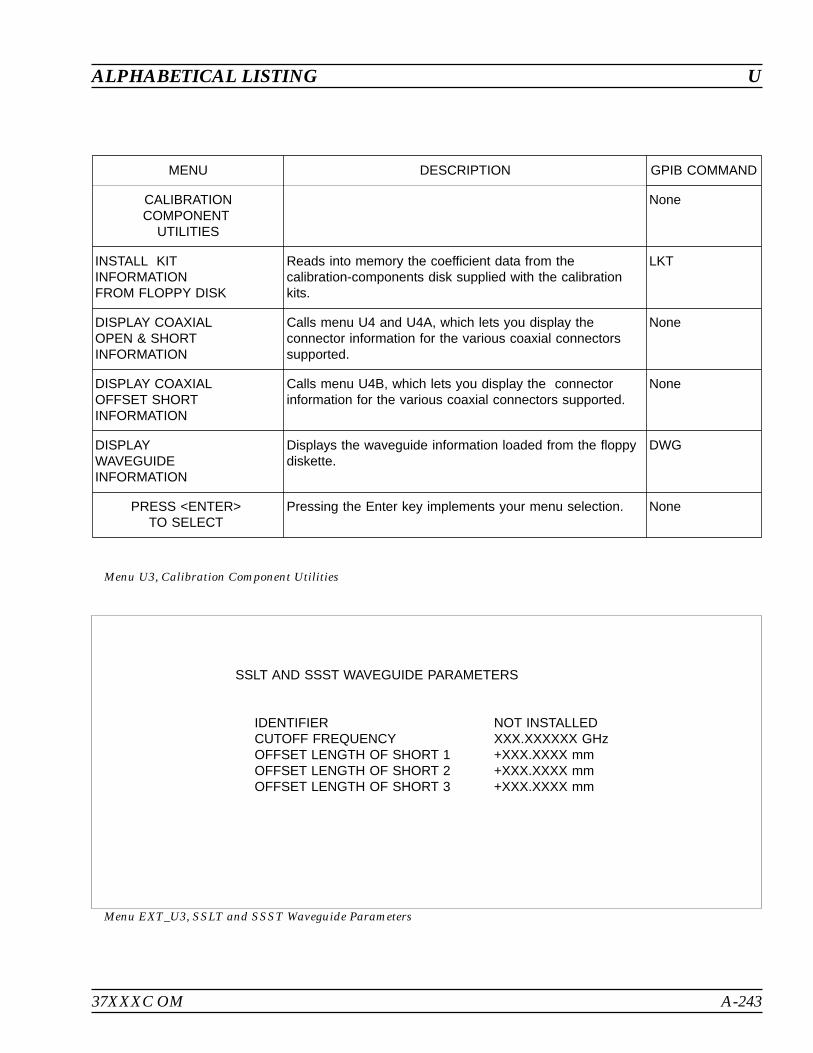
37XXXC OM A-243
ALPHABETICAL LISTING U
MENU DESCRIPTION GPIB COMMAND
CALIBRATIONCOMPONENT
UTILITIES
None
INSTALL KITINFORMATIONFROM FLOPPY DISK
Reads into memory the coefficient data from thecalibration-components disk supplied with the calibrationkits.
LKT
DISPLAY COAXIALOPEN & SHORTINFORMATION
Calls menu U4 and U4A, which lets you display theconnector information for the various coaxial connectorssupported.
None
DISPLAY COAXIALOFFSET SHORTINFORMATION
Calls menu U4B, which lets you display the connectorinformation for the various coaxial connectors supported.
None
DISPLAYWAVEGUIDEINFORMATION
Displays the waveguide information loaded from the floppydiskette.
DWG
PRESS <ENTER>TO SELECT
Pressing the Enter key implements your menu selection. None
Menu U3, Calibration Component Utilities
SSLT AND SSST WAVEGUIDE PARAMETERS
IDENTIFIER NOT INSTALLEDCUTOFF FREQUENCY XXX.XXXXXX GHzOFFSET LENGTH OF SHORT 1 +XXX.XXXX mmOFFSET LENGTH OF SHORT 2 +XXX.XXXX mmOFFSET LENGTH OF SHORT 3 +XXX.XXXX mm
Menu EXT_U3, SSLT and SSST Waveguide Parameters
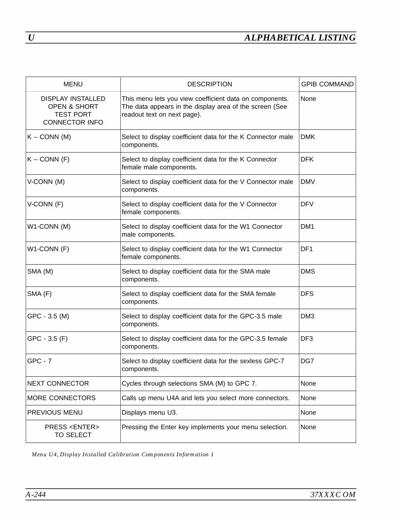
A-244 37XXXC OM
U ALPHABETICAL LISTING
MENU DESCRIPTION GPIB COMMAND
DISPLAY INSTALLEDOPEN & SHORT
TEST PORTCONNECTOR INFO
This menu lets you view coefficient data on components.The data appears in the display area of the screen (Seereadout text on next page).
None
K – CONN (M) Select to display coefficient data for the K Connector malecomponents.
DMK
K – CONN (F) Select to display coefficient data for the K Connectorfemale male components.
DFK
V-CONN (M) Select to display coefficient data for the V Connector malecomponents.
DMV
V-CONN (F) Select to display coefficient data for the V Connectorfemale components.
DFV
W1-CONN (M) Select to display coefficient data for the W1 Connectormale components.
DM1
W1-CONN (F) Select to display coefficient data for the W1 Connectorfemale components.
DF1
SMA (M) Select to display coefficient data for the SMA malecomponents.
DMS
SMA (F) Select to display coefficient data for the SMA femalecomponents.
DFS
GPC - 3.5 (M) Select to display coefficient data for the GPC-3.5 malecomponents.
DM3
GPC - 3.5 (F) Select to display coefficient data for the GPC-3.5 femalecomponents.
DF3
GPC - 7 Select to display coefficient data for the sexless GPC-7components.
DG7
NEXT CONNECTOR Cycles through selections SMA (M) to GPC 7. None
MORE CONNECTORS Calls up menu U4A and lets you select more connectors. None
PREVIOUS MENU Displays menu U3. None
PRESS <ENTER>TO SELECT
Pressing the Enter key implements your menu selection. None
Menu U4, Display Installed Calibration Components Information 1
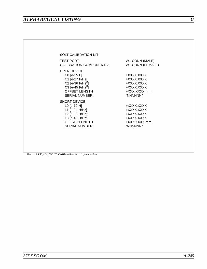
37XXXC OM A-245
ALPHABETICAL LISTING U
SOLT CALIBRATION KIT
TEST PORT: W1-CONN (MALE)CALIBRATION COMPONENTS: W1-CONN (FEMALE)
OPEN DEVICEC0 [e-15 F] +XXXX.XXXXC1 [e-27 F/Hz] +XXXX.XXXXC2 [e-36 F/Hz2] +XXXX.XXXXC3 [e-45 F/Hz3] +XXXX.XXXXOFFSET LENGTH +XXX.XXXX mmSERIAL NUMBER “NNNNNN”
SHORT DEVICEL0 [e-12 H] +XXXX.XXXXL1 [e-24 H/Hz] +XXXX.XXXXL2 [e-33 H/Hz2] +XXXX.XXXXL3 [e-42 H/Hz3] +XXXX.XXXXOFFSET LENGTH +XXX.XXXX mmSERIAL NUMBER “NNNNNN”
Menu EXT_U4, SOLT Calibration Kit Information

A-246 37XXXC OM
U ALPHABETICAL LISTING
MENU DESCRIPTION GPIB COMMAND
DISPLAYINSTALLED
CALIBRATIONCOMPONENTINFORMATION
This menu lets you view coefficient data for connectors.The data appears in the display area of the screen.
None
TYPE N (M) Select to display coefficient data for the Type N malecomponents.
DMN
TYPE N (F) Select to display coefficient data for the Type N femalecomponents.
DFN
TYPE N (M) 75 Select to display coefficient data for the Type N male 75
components.DMN75
TYPE N (F) 75 Select to display coefficient data for the Type N female 75
components.DFN75
7/16 (M) Select to display coefficient data for the 7/16 malecomponents.
DM7
7/16 (F) Select to display coefficient data for the 7/16 female malecomponents.
DF7
TNC (M) Select to display coefficient data for the TNC malecomponents.
DMT
TNC (F) Select to display coefficient data for the TNC female malecomponents.
DFT
2.4 mm (M) Select to display coefficient data for the 2.4 mm malecomponents.
DM2
2.4 mm (F) Select to display coefficient data for the 2.4 mm femalecomponents.
DF2
NEXT CONNECTOR Cycles through selections V Connector to SPECIAL. None
MORE CONNECTORS Calls up menu U4A and lets you select more connectors. None
PREVIOUS MENU Returns you to menu U3. None
PRESS <ENTER>TO SELECT
Pressing the Enter key implements your menu selection. None
Menu U4A, Display Installed Calibration Components Information 2
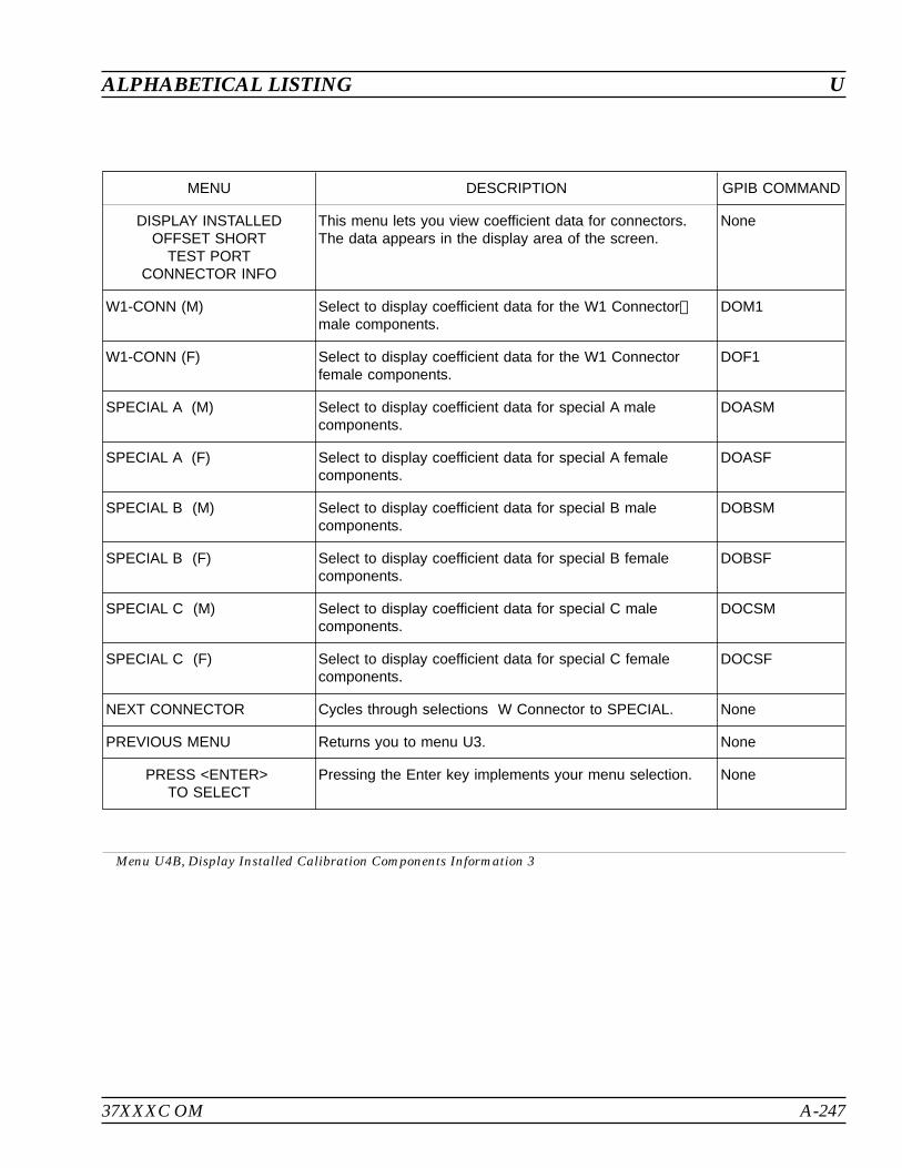
37XXXC OM A-247
ALPHABETICAL LISTING U
MENU DESCRIPTION GPIB COMMAND
DISPLAY INSTALLEDOFFSET SHORT
TEST PORTCONNECTOR INFO
This menu lets you view coefficient data for connectors.The data appears in the display area of the screen.
None
W1-CONN (M) Select to display coefficient data for the W1 Connectormale components.
DOM1
W1-CONN (F) Select to display coefficient data for the W1 Connectorfemale components.
DOF1
SPECIAL A (M) Select to display coefficient data for special A malecomponents.
DOASM
SPECIAL A (F) Select to display coefficient data for special A femalecomponents.
DOASF
SPECIAL B (M) Select to display coefficient data for special B malecomponents.
DOBSM
SPECIAL B (F) Select to display coefficient data for special B femalecomponents.
DOBSF
SPECIAL C (M) Select to display coefficient data for special C malecomponents.
DOCSM
SPECIAL C (F) Select to display coefficient data for special C femalecomponents.
DOCSF
NEXT CONNECTOR Cycles through selections W Connector to SPECIAL. None
PREVIOUS MENU Returns you to menu U3. None
PRESS <ENTER>TO SELECT
Pressing the Enter key implements your menu selection. None
Menu U4B, Display Installed Calibration Components Information 3
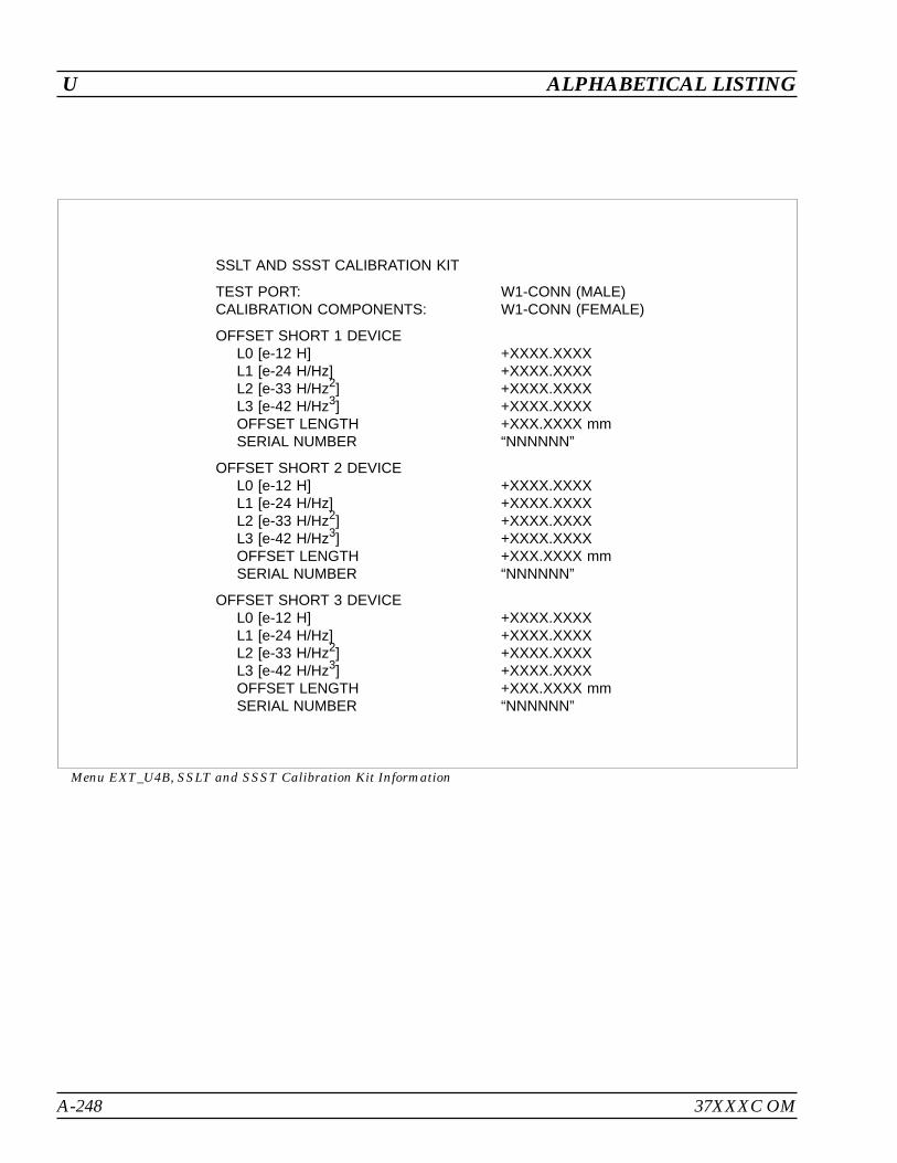
A-248 37XXXC OM
U ALPHABETICAL LISTING
SSLT AND SSST CALIBRATION KIT
TEST PORT: W1-CONN (MALE)CALIBRATION COMPONENTS: W1-CONN (FEMALE)
OFFSET SHORT 1 DEVICEL0 [e-12 H] +XXXX.XXXXL1 [e-24 H/Hz] +XXXX.XXXXL2 [e-33 H/Hz2] +XXXX.XXXXL3 [e-42 H/Hz3] +XXXX.XXXXOFFSET LENGTH +XXX.XXXX mmSERIAL NUMBER “NNNNNN”
OFFSET SHORT 2 DEVICEL0 [e-12 H] +XXXX.XXXXL1 [e-24 H/Hz] +XXXX.XXXXL2 [e-33 H/Hz2] +XXXX.XXXXL3 [e-42 H/Hz3] +XXXX.XXXXOFFSET LENGTH +XXX.XXXX mmSERIAL NUMBER “NNNNNN”
OFFSET SHORT 3 DEVICEL0 [e-12 H] +XXXX.XXXXL1 [e-24 H/Hz] +XXXX.XXXXL2 [e-33 H/Hz2] +XXXX.XXXXL3 [e-42 H/Hz3] +XXXX.XXXXOFFSET LENGTH +XXX.XXXX mmSERIAL NUMBER “NNNNNN”
Menu EXT_U4B, SSLT and SSST Calibration Kit Information
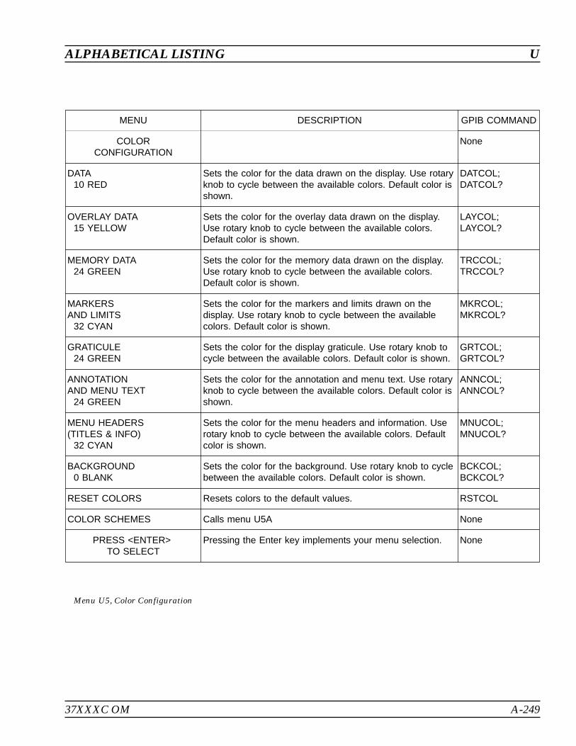
37XXXC OM A-249
ALPHABETICAL LISTING U
MENU DESCRIPTION GPIB COMMAND
COLORCONFIGURATION
None
DATA10 RED
Sets the color for the data drawn on the display. Use rotaryknob to cycle between the available colors. Default color isshown.
DATCOL;DATCOL?
OVERLAY DATA15 YELLOW
Sets the color for the overlay data drawn on the display.Use rotary knob to cycle between the available colors.Default color is shown.
LAYCOL;LAYCOL?
MEMORY DATA24 GREEN
Sets the color for the memory data drawn on the display.Use rotary knob to cycle between the available colors.Default color is shown.
TRCCOL;TRCCOL?
MARKERSAND LIMITS
32 CYAN
Sets the color for the markers and limits drawn on thedisplay. Use rotary knob to cycle between the availablecolors. Default color is shown.
MKRCOL;MKRCOL?
GRATICULE24 GREEN
Sets the color for the display graticule. Use rotary knob tocycle between the available colors. Default color is shown.
GRTCOL;GRTCOL?
ANNOTATIONAND MENU TEXT
24 GREEN
Sets the color for the annotation and menu text. Use rotaryknob to cycle between the available colors. Default color isshown.
ANNCOL;ANNCOL?
MENU HEADERS(TITLES & INFO)
32 CYAN
Sets the color for the menu headers and information. Userotary knob to cycle between the available colors. Defaultcolor is shown.
MNUCOL;MNUCOL?
BACKGROUND0 BLANK
Sets the color for the background. Use rotary knob to cyclebetween the available colors. Default color is shown.
BCKCOL;BCKCOL?
RESET COLORS Resets colors to the default values. RSTCOL
COLOR SCHEMES Calls menu U5A None
PRESS <ENTER>TO SELECT
Pressing the Enter key implements your menu selection. None
Menu U5, Color Configuration

A-250 37XXXC OM
U ALPHABETICAL LISTING
MENU DESCRIPTION GPIB COMMAND
COLOR SCHEMES The user can select various color configurations by choosing betweenpredetermined schemes
RESET COLORS Loads the current color configuration with the reset (default) colors RSTCOL
NEW COLORS Loads the color configuration with the new colors for the "C" models. NEWCO
CLASSIC COLORS Loads the color configuration with the classic colors used in past mod-els.
CLASS
INVERSE COLORS Loads the color configuration with the colors pre-defined for a whitebackground.
INVER
BRILLIANT COLORS Loads the color configuration with a pre-defined color set. BRILL
SOFT COLORS Loads the color configuration with a pre-defined color set. SOFTCO
TO CUSTOMIZE,SELECT A COLORSCHEME AND/ORMODIFY THE COLORCONFIG, THENSTORE AS RESET
The user may also store the current color configuration as the resetcolors used in <default>. Only <default-0> will restore the colors to theCLASSIC or NEW (“C” Models) setup.
None
STORE COLORCONFIG AS RESET(DEFAULT) COLORS
Stores the current color configuration as the reset colors used in <de-fault> and as the reset color scheme.
STOCO
PREVIOUS MENU Returns you to menu U3. None
PRESS <ENTER>TO SELECT
Pressing the Enter key implements your menu selection. None
Menu U5, Color Configuration

37XXXC OM A-251/A-252
ALPHABETICAL LISTING U
MENU DESCRIPTION GPIB COMMAND
SET DATE/TIME None
YEARXXXX
Sets the year. DATE; DATE?
MONTHXX
Sets the month. DATE; DATE?
DAYXX
Sets the day. DATE; DATE?
HOURXX
Sets the hour. TIME; TIME?
MINUTEXX
Sets the minute. TIME; TIME?
DONE,(SET DATE/TIME)
Prompts to set a new time. None
PREVIOUS MENU(DATE/TIMENOT SET)
Returns to the previous menu. None
PRESS <ENTER>TO SELECT
Pressing the Enter key implements your menu selection. None
Menu U6, Set Date/Time


Table of Contents
B-1 INTRODUCTION . . . . . . . . . . . . . . . . . . . . . . . . . . . . . . B-3
B-2 REAR PANEL . . . . . . . . . . . . . . . . . . . . . . . . . . . . . . . . B-3
B-3 CONNECTOR PINOUT DIAGRAMS. . . . . . . . . . . . . . . . . . . . B-3
Appendix BRear Panel Connectors


Appendix BRear Panel Connectors
B-1 INTRODUCTION This appendix provides descriptions and pinout diagrams for the37XXXC rear panel connectors .
B-2 REAR PANEL The 37XXXC rear panel connectors are described if Figures B-1 andB-2 on page B-2 and B-3.
B-3 CONNECTOR PINOUTDIAGRAMS
Figures B-3 through B-10 provide pinout diagrams for the rear panelconnectors.
37XXXC OM B-3

B-4 37XXXC OM
REAP PANEL DRAWINGS REAR PANEL CONNECTORS
Figure B-1. 372XXC, 373XXC Rear Panel
External I/O
Display
IEEE488.2GPIB
10MHzRef
ExtTrigger
ExtAnlgIn
SAMETYPEANDRATING
85-264VAC48-63HzFORCONTINUEDFIREPROTECTIONREPLACEONLYWITHSPECIFIEDTYPEANDRATEDFUSE
540VAMAX
VGAOUT
Printer Out
WARNINGNOOPERATORSERVICE-ABLEPARTSINSIDEREFERSERVICINGTOQUALIFIEDPERSONNEL
CAUTION
SH
1
AH
1
T6
L4
SR
1
RL
1
PP
1
DC
1
DT
1
C0
E2
Refer tomanualfor GPIBaddress
1n±5dBm50W Out 0dBm50W
ExtAnlgOut
!
REPLACEFUSEONLYWITH
! CAUTION
> 18 kgHEAVYWEIGHT
Port1SourceAtten
Port2TestAtten Transfer
Switch
Figure B-2. 371XXC Rear Panel
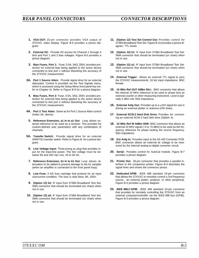
37XXXC OM B-5
REAR PANEL CONNECTORS CONNECTOR DESCRIPTIONS
1. VGA OUT: 15-pin connector provides VGA output of37XXXC video display. Figure B-6 provides a pinout dia-gram.
2. External I/O: Provide I/O access for Channel 1 through 4limit and Port 1 and 2 bias voltages. Figure B-5 provides apinout diagram.
3. Bias Fuses, Port 1: Fuse, 0.5A, 3AG, 250V, provides pro-tection for external bias being applied to the active deviceconnected to test port 1 without disturbing the accuracy ofthe 37XXXC measurement.
3A. Port 1 Source Atten: Provide signal drive for an externalattenuator. Control is provided via the Test Signals menu,which is accessed using the Setup Menu front panel key (re-fer to Chapter 4). Refer to Figure B-9 for a pinout diagram.
4. Bias Fuses, Port 2: Fuse, 0.5A, 3AG, 250V, provides pro-tection for external bias being applied to the active deviceconnected to test port 2 without disturbing the accuracy ofthe 37XXXC measurement.
4A. Port 2 Test Atten: Same as for Port 1 Source Atten control(Index 3A, above).
5. Reference Extension, a1 In to a1 Out: Loop allows ex-ternal reference to be used as a receiver. This provides forcustom-defined user parameters with any combination ofchannels.
5A. Transfer Switch: Provide signal drive for an externalANRITSU transfer switch. Refer to Figure B- for a pinout dia-gram.
6. Line Voltage Input: Three-prong ac plug that provides in-put for the input-line power. The line voltage must be be-tween 85 and 264 Vac rms, 43 to 63 Hz.
7. Reference Extension, b1 In to b1 Out: Loop allows at-tenuation to be added to prevent damage to the b1 sampler(when an amplifier is connected to the front panel loop).
8. Line Fuse: 3 AG fuse cartridge that protects for an inputovercurrent condition. The fuse is slow blow, 8A, 250V.
9. (Option 12) b2: IF input from 3738A Broadband Test Set.SMA connector that should be terminated (on chain) whennot in use.
10. (Option 12) a2: IF input from 3738A Broadband Test Set.SMA connector that should be terminated (on chain) whennot in use.
11. (Option 12) Test Set Control Out: Provides control for3738A Broadband Test Set. Figure B-10 provides a pinout di-agram. TTL levels.
12. (Option 12) b1: IF input from 3738A Broadband Test Set.SMA connector that should be terminated (on chain) whennot in use.
13. (Option 12) a1: IF input from 3738A Broadband Test Set.SMA connector that should be terminated (on chain) whennot in use.
14. External Trigger: Allows an external TTL signal to syncthe 37XXXC measurements; 10 k input impedance, BNCfemale.
15. 10 MHz Ref OUT 0dBm 50: BNC connector that allowsthe internal 10 MHz reference to be used to phase lock anexternal counter or other measuring instrument. Level is typi-cally 0 dBm into 50 impedance.
16. External Anlg Out: Provides up to a 10V signal for use indriving an external plotter or antenna (CW draw).
17. External SCSI-2 Hard Disk Drive: Provides for connect-ing an external SCSI-2 hard disk drive (Option 4).
18. 10 MHz Ref IN 0dBm 50W: BNC connector that allows anexternal 10 MHz signal (–5 to +5 dBm) to be used as the fre-quency reference for phase locking the source frequency.50 impedance.
19. Ext Anlg In: Provides input to the A5 A/D Converter PCB.BNC connector allows an external dc voltage to be mea-sured by the internal analog-to-digital converter circuit.
20. Serial: Provides control for AutoCal module. Figure B-7provides a pinout diagram.
21. Printer Out: 36-pin connector that provides a parallel in-terface to the companion printer. Figure B-4 describes thesignal lines and shows the connector pinout.
22. Dedicated GPIB: IEEE 488 standard 24-pin connectorthat allows the 37XXXC to remotely control a 2nd frequencysource, an external plotter, analyzer, or other peripheral.Figure B-3 provides a pinout diagram.
23. IEEE 488.2 GPIB: IEEE 488 standard 24-pin connectorthat provides for remotely controlling the 37XXXC from anexternal computer/controller via the IEEE-488 bus (GPIB).Figure B-3 provides a pinout diagram.

B-6 37XXXC OM
CONNECTOR PINOUT DIAGRAMS REAR PANEL CONNECTORS
121110987654321
242322212019181716151413
Pinout Diagram
PIN NAME DESCRIPTION
1-4 DIO 1 through DIO 4 Data Input/Output. Bits are HIGH with the data is logical 0 and LOW when the data islogical 1.
5 EOI End Or Identify. A low-true state indicates that the last byte of a multibyte messagehas been placed on the line.
6 DAV Data Valid. A low-true state indicates that the talker has (1) sensed that NRFD isLOW, (2) placed a byte of data on the bus, and (3) waited an appropriate length oftime for the data to settle.
7 NRFD Not Ready For Data. A high-true state indicates that valid data has not yet been ac-cepted by a listener.
8 NDAC Not Data Accepted. A high-false state indicates that the current data byte has beenaccepted for internal processing by a listener.
9 IFC Interface Clear. A low-true state places all bus instruments in a known state—suchas, unaddressed to talk, unaddressed to listen, and service request idle.
10 SRQ Service Request. A low-true state indicates that a bus instrument needs service fromthe controller.
11 ATN Attention. A low-true state enables the controller to respond to both it’s own lis-ten/talk address and to appropriate interface messages — such as, device clear andserial poll.
12 Shield Chassis ground.
13-16 DIO 5 through DIO 8 Data Input/Output. Bits are high with the data is logical 0 and LOW when the data islogical 1.
17 REN Remote Enable. A low-true state enables bus instruments to be operated remotely,when addressed.
18-
24 GND Logic ground.
Figure B-3. Pinout Diagram, GPIB and Dedicated GPIB Connectors
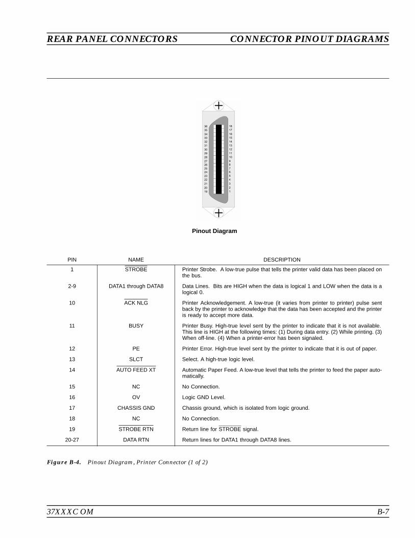
37XXXC OM B-7
REAR PANEL CONNECTORS CONNECTOR PINOUT DIAGRAMS
Pinout Diagram
PIN NAME DESCRIPTION
1 STROBE Printer Strobe. A low-true pulse that tells the printer valid data has been placed onthe bus.
2-9 DATA1 through DATA8 Data Lines. Bits are HIGH when the data is logical 1 and LOW when the data is alogical 0.
10 ACK NLG Printer Acknowledgement. A low-true (it varies from printer to printer) pulse sentback by the printer to acknowledge that the data has been accepted and the printeris ready to accept more data.
11 BUSY Printer Busy. High-true level sent by the printer to indicate that it is not available.This line is HIGH at the following times: (1) During data entry. (2) While printing. (3)When off-line. (4) When a printer-error has been signaled.
12 PE Printer Error. High-true level sent by the printer to indicate that it is out of paper.
13 SLCT Select. A high-true logic level.
14 AUTO FEED XT Automatic Paper Feed. A low-true level that tells the printer to feed the paper auto-matically.
15 NC No Connection.
16 OV Logic GND Level.
17 CHASSIS GND Chassis ground, which is isolated from logic ground.
18 NC No Connection.
19 STROBE RTN Return line for STROBE signal.
20-27 DATA RTN Return lines for DATA1 through DATA8 lines.
Figure B-4. Pinout Diagram, Printer Connector (1 of 2)
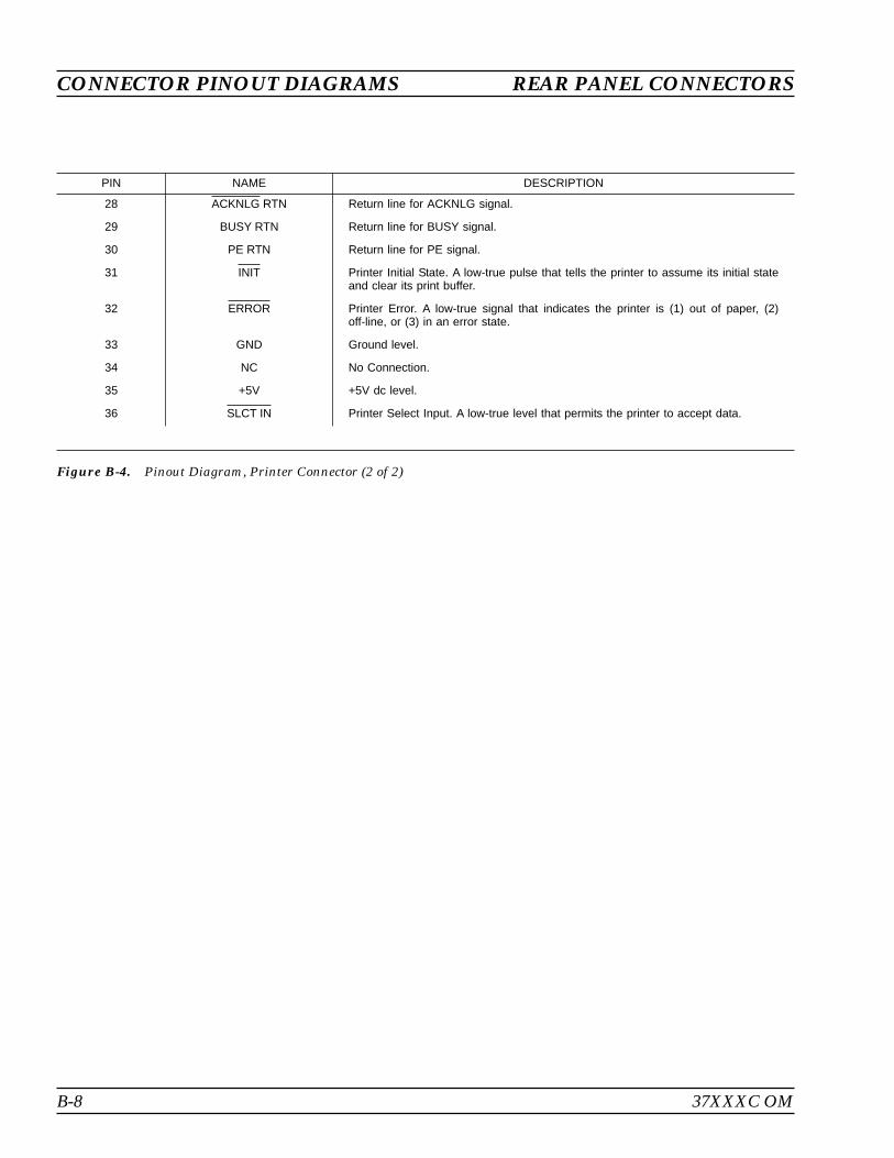
B-8 37XXXC OM
CONNECTOR PINOUT DIAGRAMS REAR PANEL CONNECTORS
PIN NAME DESCRIPTION
28 ACKNLG RTN Return line for ACKNLG signal.
29 BUSY RTN Return line for BUSY signal.
30 PE RTN Return line for PE signal.
31 INIT Printer Initial State. A low-true pulse that tells the printer to assume its initial stateand clear its print buffer.
32 ERROR Printer Error. A low-true signal that indicates the printer is (1) out of paper, (2)off-line, or (3) in an error state.
33 GND Ground level.
34 NC No Connection.
35 +5V +5V dc level.
36 SLCT IN Printer Select Input. A low-true level that permits the printer to accept data.
Figure B-4. Pinout Diagram, Printer Connector (2 of 2)
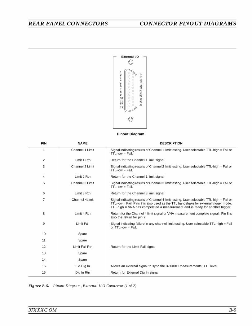
37XXXC OM B-9
REAR PANEL CONNECTORS CONNECTOR PINOUT DIAGRAMS
External I/O
12345678910111213
141516171819202122232425
Pinout Diagram
PIN NAME DESCRIPTION
1 Channel 1 Limit Signal indicating results of Channel 1 limit testing. User selectable TTL-high = Fail orTTL-low = Fail.
2 Limit 1 Rtn Return for the Channel 1 limit signal
3 Channel 2 Limit Signal indicating results of Channel 2 limit testing. User selectable TTL-high = Fail orTTL-low = Fail.
4 Limit 2 Rtn Return for the Channel 1 limit signal
5 Channel 3 Limit Signal indicating results of Channel 3 limit testing. User selectable TTL-high = Fail orTTL-low = Fail.
6 Limit 3 Rtn Return for the Channel 3 limit signal
7 Channel 4Limit Signal indicating results of Channel 4 limit testing. User selectable TTL-high = Fail orTTL-low = Fail. Pins 7 is also used as the TTL handshake for external trigger mode.TTL-high = VNA has compeleted a measurement and is ready for another trigger
8 Limit 4 Rtn Return for the Channel 4 limit signal or VNA measurement complete signal. Pin 8 isalso the return for pin 7.
9 Limit Fail Signal indicating failure in any channel limit testing. User selectable TTL-high = Failor TTL-low = Fail.
10 Spare
11 Spare
12 Limit Fail Rtn Return for the Limit Fail signal
13 Spare
14 Spare
15 Ext Dig In Allows an external signal to sync the 37XXXC measurements; TTL level
16 Dig In Rtn Return for External Dig In signal
Figure B-5. Pinout Diagram, External I/O Connector (1 of 2)
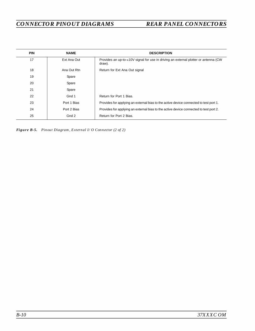
B-10 37XXXC OM
CONNECTOR PINOUT DIAGRAMS REAR PANEL CONNECTORS
PIN NAME DESCRIPTION
17 Ext Ana Out Provides an up-to-10V signal for use in driving an external plotter or antenna (CWdraw).
18 Ana Out Rtn Return for Ext Ana Out signal
19 Spare
20 Spare
21 Spare
22 Gnd 1 Return for Port 1 Bias.
23 Port 1 Bias Provides for applying an external bias to the active device connected to test port 1.
24 Port 2 Bias Provides for applying an external bias to the active device connected to test port 2.
25 Gnd 2 Return for Port 2 Bias.
Figure B-5. Pinout Diagram, External I/O Connector (2 of 2)

37XXXC OM B-11
REAR PANEL CONNECTORS CONNECTOR PINOUT DIAGRAMS
109876
1514131211
54321
PIN NAME DESCRIPTION
1 Red Red signal
2 Green Green signal
3 Blue Blue signal
4 Not Used
5 Not Used
6 Red Return Red return
7 Green Return Green return
8 Blue Return Blue return
9 Not Used
10 Digital Ground Sync ground
11 Not Used
12 Not Used
13 Hsync Horizontal sync
14 Vsync Vertical sync
15 Not Used
Figure B-6. Pinout Diagram, VGA IN/OUT Connector
Pinout Diagram
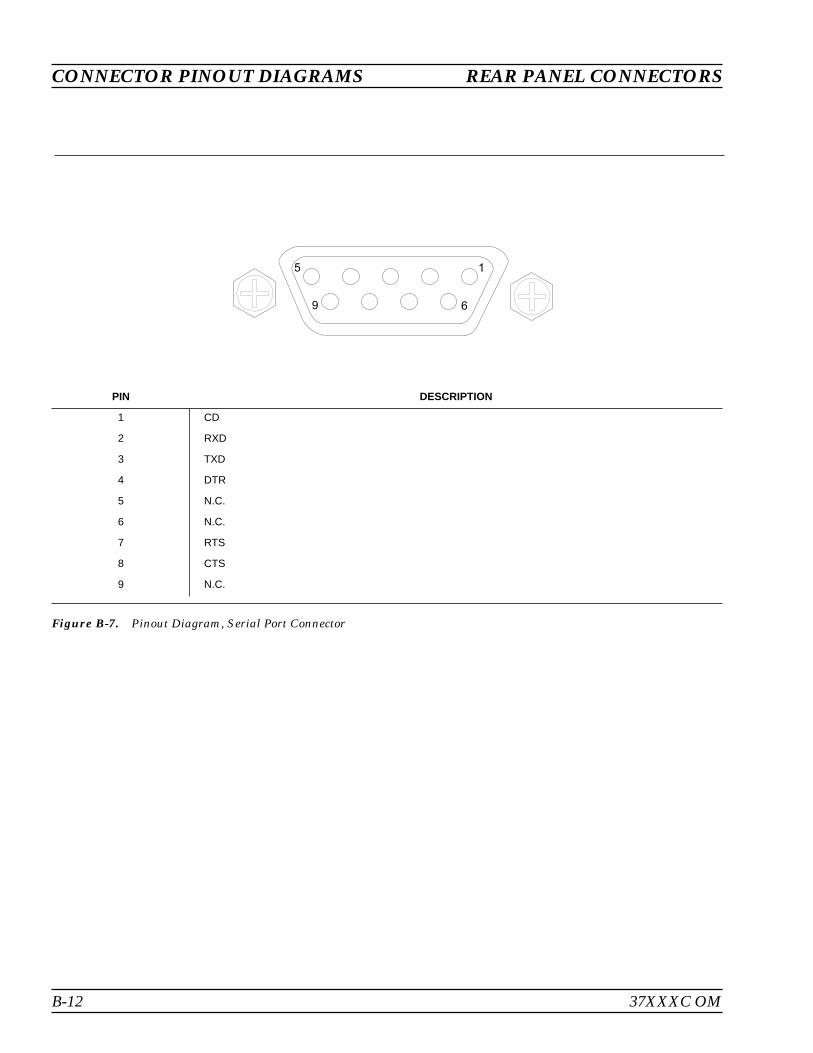
B-12 37XXXC OM
CONNECTOR PINOUT DIAGRAMS REAR PANEL CONNECTORS
1
6
5
9
PIN DESCRIPTION
1 CD
2 RXD
3 TXD
4 DTR
5 N.C.
6 N.C.
7 RTS
8 CTS
9 N.C.
Figure B-7. Pinout Diagram, Serial Port Connector
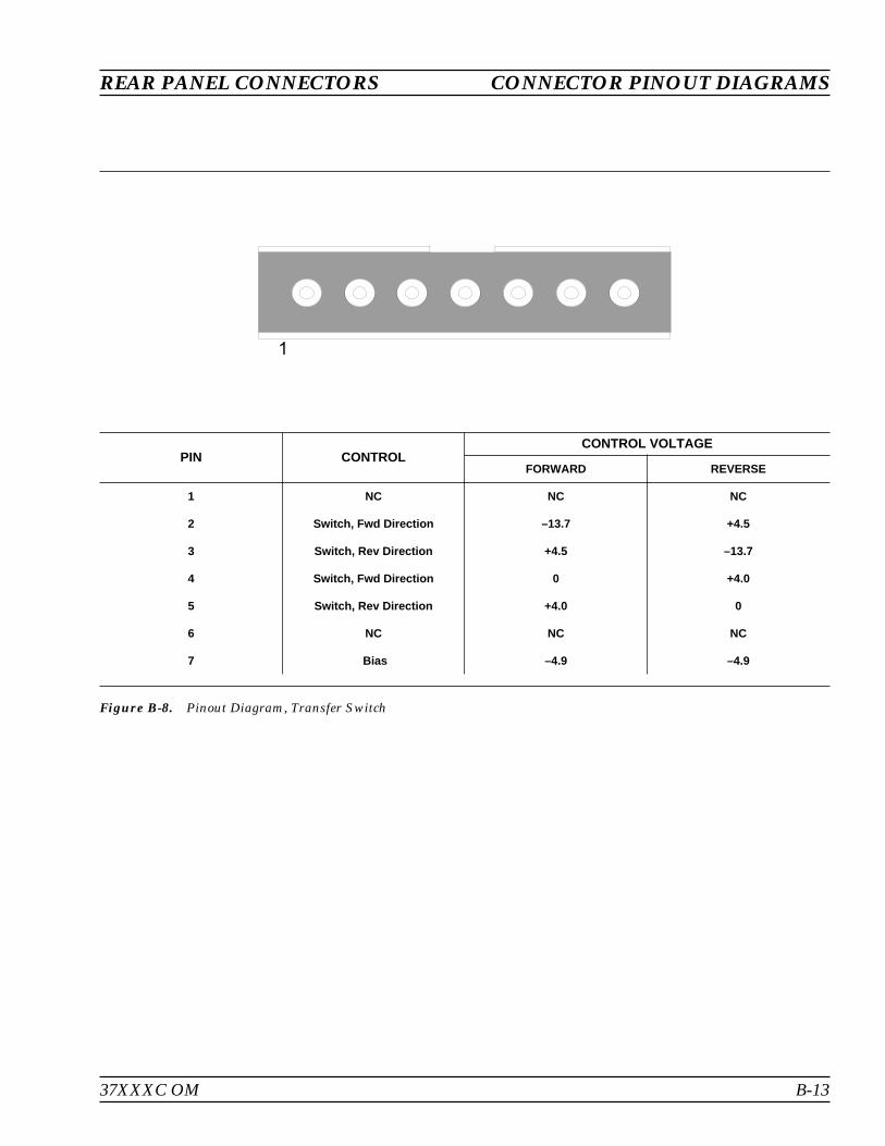
37XXXC OM B-13
REAR PANEL CONNECTORS CONNECTOR PINOUT DIAGRAMS
PIN CONTROLCONTROL VOLTAGE
FORWARD REVERSE
1 NC NC NC
2 Switch, Fwd Direction –13.7 +4.5
3 Switch, Rev Direction +4.5 –13.7
4 Switch, Fwd Direction 0 +4.0
5 Switch, Rev Direction +4.0 0
6 NC NC NC
7 Bias –4.9 –4.9
Figure B-8. Pinout Diagram, Transfer Switch
1

B-14 37XXXC OM
CONNECTOR PINOUT DIAGRAMS REAR PANEL CONNECTORS
PIN NAME DESCRIPTION
1 Not Used
2 10 dB IN Switch 1, Position 2 (On)
3 40 dB OUT Switch 3, Position 2 (Off)
4 Not Used
5 20 dB IN Switch 2, Position 2 (On)
6 +24 Vdc +24 Vdc
7 Not Used
8 Not Used
9 40 dB IN Switch 3, Position 2 (On)
10 Not Used
11 20 dB OUT Switch 2, Position 1 (Off)
12 Not Used
13 10 dB OUT Switch 1, Position 1 (Off)
14 Not Used
Figure B-9. Pinout Diagram, Port 1 Source and Port 2 Test Connectors
1
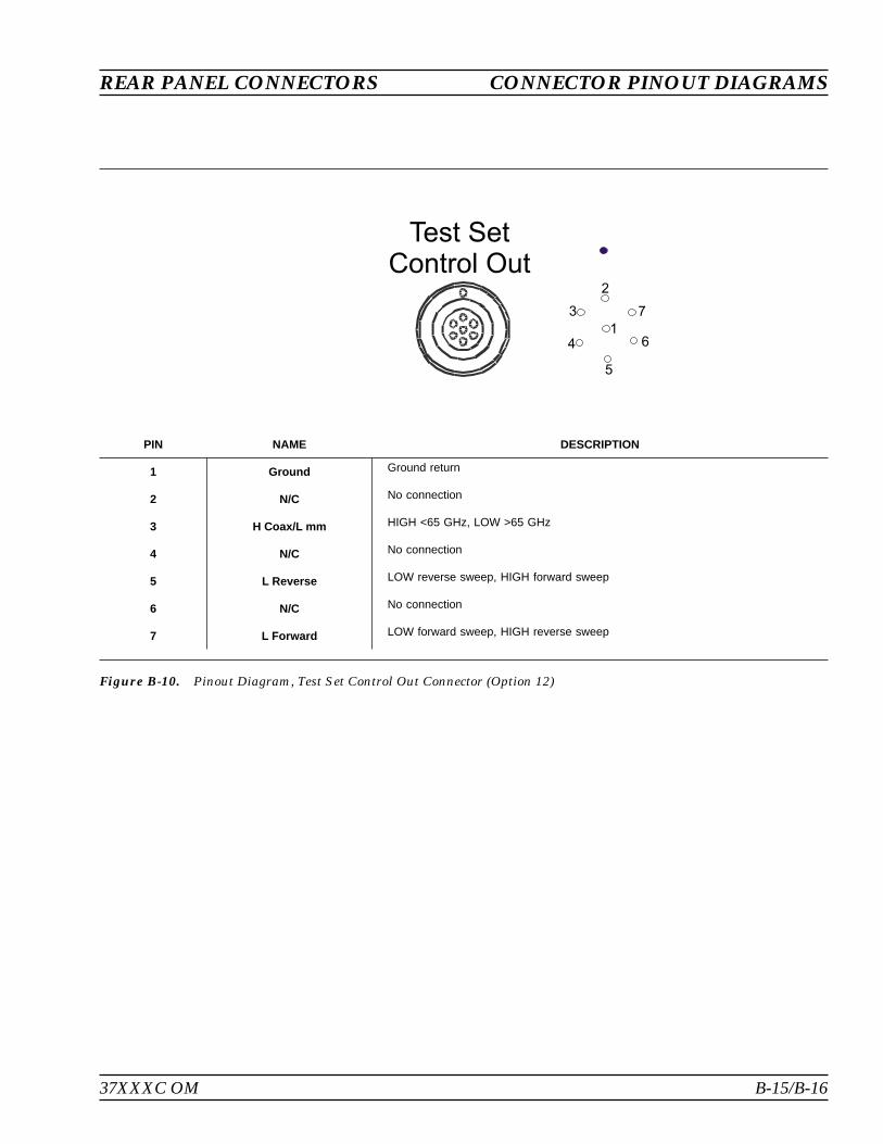
37XXXC OM B-15/B-16
REAR PANEL CONNECTORS CONNECTOR PINOUT DIAGRAMS
PIN NAME DESCRIPTION
1 Ground Ground return
2 N/C No connection
3 H Coax/L mm HIGH <65 GHz, LOW >65 GHz
4 N/C No connection
5 L Reverse LOW reverse sweep, HIGH forward sweep
6 N/C No connection
7 L Forward LOW forward sweep, HIGH reverse sweep
Figure B-10. Pinout Diagram, Test Set Control Out Connector (Option 12)
Test SetControl Out
1
2
3
4
5
6
7


Appendix CPerformance Specifications
This appendix contains a copy of the 37100C/37200C/37300C VectorNetwork Analyzers Technical Data Sheet, Anritsu Part Number11410-00247.


37100C/37200C/37300CVector Network AnalyzersTechnical Data Sheet
Vector Network Analysis up to 65 GHz
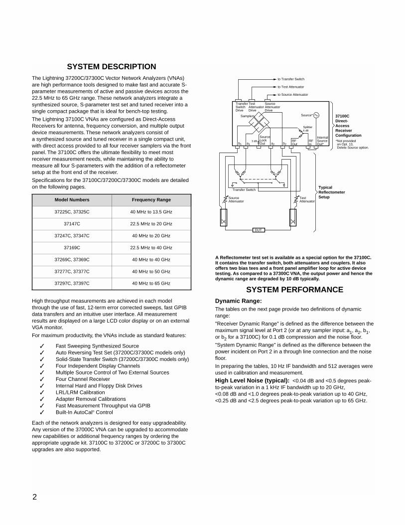
SYSTEM DESCRIPTIONThe Lightning 37200C/37300C Vector Network Analyzers (VNAs)are high performance tools designed to make fast and accurate S-parameter measurements of active and passive devices across the22.5 MHz to 65 GHz range. These network analyzers integrate asynthesized source, S-parameter test set and tuned receiver into asingle compact package that is ideal for bench-top testing.
The Lightning 37100C VNAs are configured as Direct-AccessReceivers for antenna, frequency conversion, and multiple outputdevice measurements. These network analyzers consist ofa synthesized source and tuned receiver in a single compact unit,with direct access provided to all four receiver samplers via the frontpanel. The 37100C offers the ultimate flexibility to meet mostreceiver measurement needs, while maintaining the ability tomeasure all four S-parameters with the addition of a reflectometersetup at the front end of the receiver.
Specifications for the 37100C/37200C/37300C models are detailedon the following pages.
High throughput measurements are achieved in each modelthrough the use of fast, 12-term error corrected sweeps, fast GPIBdata transfers and an intuitive user interface. All measurementresults are displayed on a large LCD color display or on an externalVGA monitor.
For maximum productivity, the VNAs include as standard features:
Fast Sweeping Synthesized Source Auto Reversing Test Set (37200C/37300C models only) Solid-State Transfer Switch (37200C/37300C models only) Four Independent Display Channels Multiple Source Control of Two External Sources Four Channel Receiver Internal Hard and Floppy Disk Drives LRL/LRM Calibration Adapter Removal Calibrations Fast Measurement Throughput via GPIB Built-In AutoCal® Control
Each of the network analyzers is designed for easy upgradeability.Any version of the 37000C VNA can be upgraded to accommodatenew capabilities or additional frequency ranges by ordering theappropriate upgrade kit. 37100C to 37200C or 37200C to 37300Cupgrades are also supported.
SYSTEM PERFORMANCEDynamic Range:The tables on the next page provide two definitions of dynamicrange:
"Receiver Dynamic Range" is defined as the difference between themaximum signal level at Port 2 (or at any sampler input: a1, a2, b1,or b2 for a 37100C) for 0.1 dB compression and the noise floor.
"System Dynamic Range" is defined as the difference between thepower incident on Port 2 in a through line connection and the noisefloor.
In preparing the tables, 10 Hz IF bandwidth and 512 averages wereused in calibration and measurement.
High Level Noise (typical): <0.04 dB and <0.5 degrees peak-to-peak variation in a 1 kHz IF bandwidth up to 20 GHz,<0.08 dB and <1.0 degrees peak-to-peak variation up to 40 GHz,<0.25 dB and <2.5 degrees peak-to-peak variation up to 65 GHz.
Model Numbers
2
A Reflectometer test set is available as a special option for the 37100C.It contains the transfer switch, both attenuators and couplers. It alsooffers two bias tees and a front panel amplifier loop for active devicetesting. As compared to a 37300C VNA, the output power and hence thedynamic range are degraded by 10 dB typically.
to Transfer Switch
to Test Attenuator
to Source Attenuator
InternalSourceOut*
RFIn
37100CDirect- AccessReceiver Configuration*Not provided *on Opt. 13,*Delete Source option.
SourceLockOutb1 b2a2a1
RFOut
Splitter6 dB
Samplers Source*
TransferSwitchDrive
TestAttenuatorDrive
SourceAttenuatorDrive
3 dB
Transfer Switch
DUT
TypicalReflectometerSetupSource
AttenuatorTestAttenuatorFrequency Range
37225C, 37325C 40 MHz to 13.5 GHz
37147C 22.5 MHz to 20 GHz
37247C, 37347C 40 MHz to 20 GHz
37169C 22.5 MHz to 40 GHz
37269C, 37369C 40 MHz to 40 GHz
37277C, 37377C 40 MHz to 50 GHz
37297C, 37397C 40 MHz to 65 GHz
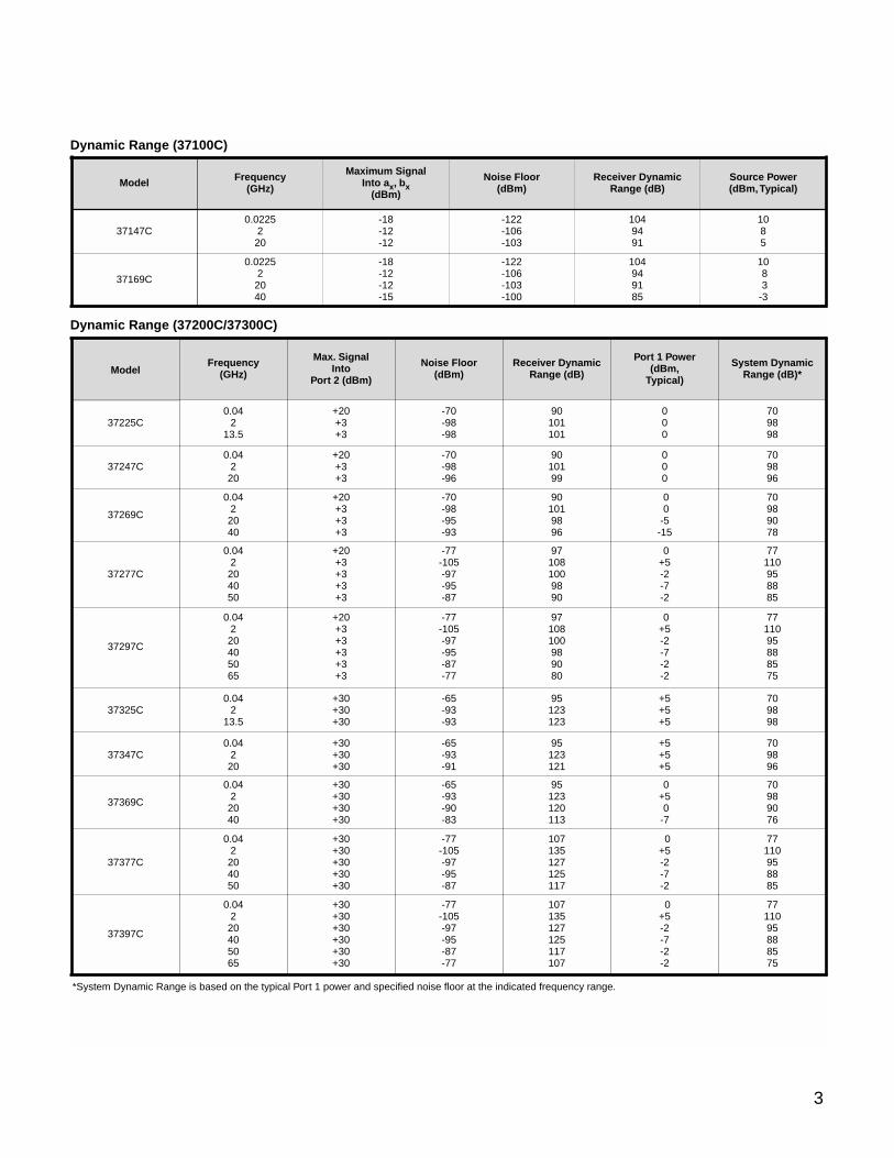
Dynamic Range (37100C)
Dynamic Range (37200C/37300C)
37369C
37347C
37377C
7711095888575
3
Model Numbers Frequency (GHz)
37147C0.0225
220
37169C0.0225
22040-18
Model Frequency (GHz)
37147C0.0225
220
37169C
0.022522040
-18-12-12-15
-18-12-12
Maximum Signal Into ax, bx
(dBm)
-122-106-103-100
-122-106-103
Noise Floor (dBm)
104949185
1049491
Receiver Dynamic Range (dB)
1083
-3
1085
Source Power (dBm,Typical)
ModelFrequency
(GHz)
Max. Signal Into
Port 2 (dBm)
Noise Floor (dBm)
Receiver DynamicRange (dB)
37225C0.04
213.5
+20+3+3
-70-98-98
90101101
Port 1 Power (dBm,
Typical)
000
000
00
-5-15
System DynamicRange (dB)*
709898
709896
70989078
37247C0.04
220
+20+3+3
-70-98-96
9010199
37269C
0.0422040
+20+3+3+3
-70-98-95-93
901019896
0+5-2-7-2
77110958885
37277C
0.042204050
+20+3+3+3+3
-77-105-97-95-87
971081009890
0+5-2-7-2-2
37397C
+30+30+30+30+30+30
-77-105-97-95-87-77
107135127125117107
0+5-2-7-2-2
7711095888575
37297C
0.04220405065
+20+3+3+3+3+3
-77-105-97-95-87-77
97108100989080
*System Dynamic Range is based on the typical Port 1 power and specified noise floor at the indicated frequency range.
37325C0.04
213.5
+5+5+5
709896
0.04220
+30+30+30
-65-93-91
95123121
+5+5+5
+30+30+30
-65-93-93
95123123
0+50
-7
70989076
0.0422040
+30+30+30+30
-65-93-90-83
95123120113
0+5-2-7-2
77110958885
+30+30+30+30+30
-77-105-97-95-87
107135127125117
0.04220405065
0.042204050
709898
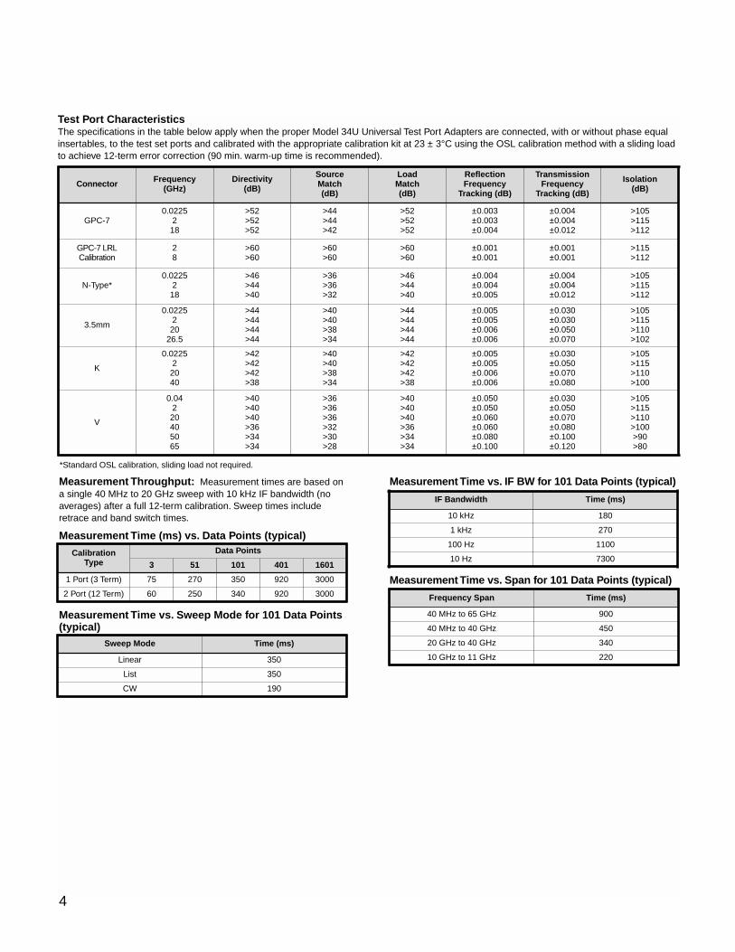
Measurement Throughput: Measurement times are based ona single 40 MHz to 20 GHz sweep with 10 kHz IF bandwidth (noaverages) after a full 12-term calibration. Sweep times includeretrace and band switch times.
Measurement Time (ms) vs. Data Points (typical)
Measurement Time vs. Sweep Mode for 101 Data Points(typical)
Measurement Time vs. IF BW for 101 Data Points (typical)
Measurement Time vs. Span for 101 Data Points (typical)
4
Test Port CharacteristicsThe specifications in the table below apply when the proper Model 34U Universal Test Port Adapters are connected, with or without phase equalinsertables, to the test set ports and calibrated with the appropriate calibration kit at 23 ± 3°C using the OSL calibration method with a sliding loadto achieve 12-term error correction (90 min. warm-up time is recommended).
Calibration Type
Data Points
1 Port (3 Term) 3000920
2 Port (12 Term)
75
300092060
3 1601
350270
340
401
250
10151
IF Bandwidth Time (ms)
10 kHz 180
1 kHz 270
100 Hz 1100
10 Hz 7300
Sweep Mode Time (ms)
Linear 350
List 350
CW 190
Frequency Span Time (ms)
40 MHz to 65 GHz 900
20 GHz to 40 GHz 340
10 GHz to 11 GHz 220
40 MHz to 40 GHz 450
Connector Frequency(GHz)
Directivity(dB)
SourceMatch(dB)
LoadMatch(dB)
ReflectionFrequency
Tracking (dB)
GPC-70.0225
218
>52>52>52
>44>44>42
>52>52>52
±0.003±0.003±0.004
GPC-7 LRL Calibration
28
>60>60
>60>60
>60>60
±0.001±0.001
N-Type*0.0225
218
>46>44>40
>36>36>32
>46>44>40
±0.004±0.004±0.005
3.5mm
0.0225220
26.5
>44>44>44>44
>40>40>38>34
>44>44>44>44
±0.005±0.005±0.006±0.006
K
0.022522040
>42>42>42>38
>40>40>38>34
>42>42>42>38
±0.005±0.005±0.006±0.006
V
0.04220405065
>40>40>40>36>34>34
>36>36>36>32>30>28
>40>40>40>36>34>34
±0.050±0.050±0.060±0.060±0.080±0.100
TransmissionFrequency
Tracking (dB)
±0.004±0.004±0.012
±0.001±0.001
±0.004±0.004±0.012
±0.030±0.030±0.050±0.070
±0.030±0.050±0.070±0.080
±0.030±0.050±0.070±0.080±0.100±0.120
Isolation(dB)
>105>115>112
>115>112
>105>115>112
>105>115>110>102
>105>115>110>100
>105>115>110>100>90>80
*Standard OSL calibration, sliding load not required.
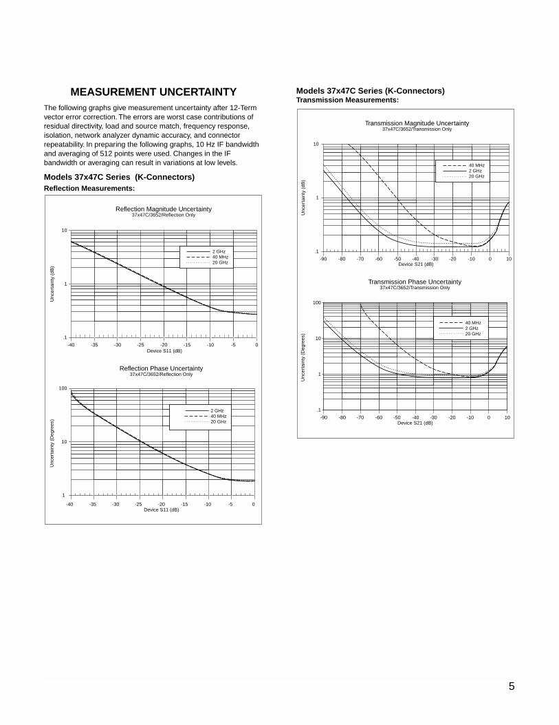
MEASUREMENT UNCERTAINTYThe following graphs give measurement uncertainty after 12-Termvector error correction. The errors are worst case contributions ofresidual directivity, load and source match, frequency response,isolation, network analyzer dynamic accuracy, and connectorrepeatability. In preparing the following graphs, 10 Hz IF bandwidthand averaging of 512 points were used. Changes in the IFbandwidth or averaging can result in variations at low levels.
Models 37x47C Series (K-Connectors)Reflection Measurements:
Models 37x47C Series (K-Connectors)Transmission Measurements:
Device S21 (dB)
Unc
erta
inty
(dB
)
Transmission Magnitude Uncertainty37x47C/3652/Transmission Only
10
1
.1
-70 -60 -50 -40 -30 -20 -10 0 10-80-90
40 MHz2 GHz20 GHz
40 MHz2 GHz20 GHz
Transmission Phase Uncertainty37x47C/3652/Transmission Only
Unc
erta
inty
(D
egre
es)
100
10
1
.1
Device S21 (dB)-90 -80 -70 -60 -50 -40 -30 -20 -10 0 10
Reflection Magnitude Uncertainty37x47C/3652/Reflection Only
Unc
erta
inty
(dB
)
10
1
.1
-40 -35 -30 -25 -20 -15 -10 -5 0
2 GHz40 MHz20 GHz
Reflection Phase Uncertainty37x47C/3652/Reflection Only
Device S11 (dB)
Device S11 (dB)
Unc
erta
inty
(D
egre
es)
100
10
1
-40 -35 -30 -25 -20 -15 -10 -5 0
2 GHz40 MHz20 GHz
5
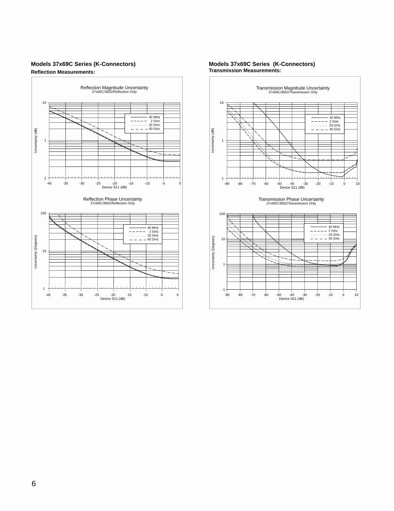
Models 37x69C Series (K-Connectors)Reflection Measurements:
Models 37x69C Series (K-Connectors)Transmission Measurements:
Device S21 (dB)
Unc
erta
inty
(dB
)
Transmission Magnitude Uncertainty37x69C/3652/Transmission Only
10
1
.1
-70 -60 -50 -40 -30 -20 -10 0 10-80-90
40 MHz2 GHz20 GHz40 GHz
Transmission Phase Uncertainty37x69C/3652/Transmission Only
Unc
erta
inty
(D
egre
es)
100
10
1
.1
Device S21 (dB)-90 -80 -70 -60 -50 -40 -30 -20 -10 0 10
40 MHz2 GHz20 GHz40 GHz
Reflection Magnitude Uncertainty37x69C/3652/Reflection Only
Device S11 (dB)
Unc
erta
inty
(dB
)
10
1
.1
-40 -35 -30 -25 -20 -15 -10 -5 0
40 MHz 2 GHz20 GHz40 GHz
Reflection Phase Uncertainty37x69C/3652/Reflection Only
Device S11 (dB)
Unc
erta
inty
(D
egre
es)
100
10
1
-40 -35 -30 -25 -20 -15 -10 -5 0
40 MHz 2 GHz20 GHz40 GHz
6

7
Model 37x77C and 37x97C (V-Connectors)Reflection Measurements:
Model 37x77C and 37x97C (V-Connectors)Transmission Measurements:
Device S21 (dB)
Unc
erta
inty
(dB
)
Transmission Magnitude Uncertainty37x97C/3654B/Transmission Only
10
1
.1
-70 -60 -50 -40 -30 -20 -10 0 10-80-90
40 MHz20 GHz40 GHz50 GHz65 GHz
100
10
1
Device S21 (dB)-40-50-60-70-80-90 -30 -20 -10 0 10
Transmission Phase Uncertainty37x97C/3654B/Transmission Only
40 MHz20 GHz40 GHz50 GHz65 GHz
Unc
erta
inty
(D
egre
es)
Reflection Magnitude Uncertainty37x97C/3654B/Reflection Only
Device S11 (dB)
Unc
erta
inty
(dB
)
10
1
.1
-40 -35 -30 -25 -20 -15 -10 -5 0
40 MHz20 GHz40 GHz50 GHz65 GHz
Reflection Phase Uncertainty37x97C/3654B/Reflection Only
Device S11 (dB)
Unc
erta
inty
(D
egre
es)
100
10
1
-40 -35 -30 -25 -20 -15 -10 -5 0
40 MHz20 GHz40 GHz50 GHz65 GHz
8
MEASUREMENT CAPABILITIESNumber of Channels: Four independent measurementchannels.
Parameters: S11, S21, S22, S12, or user defined combinationsof a1, a2, b1, and b2. All measurements are made without the needto manually reverse the test device. For the 37100C models, areflectometer setup at the front end of the receiver is required for S-measurements (See diagram on page 2).
Measurement Frequency Range: Frequency range of themeasurement can be narrowed within the calibration range withoutrecalibration. CW mode permits single frequency measurements,also without recalibration.
Domains: Frequency Domain, CW Draw, and optional HighSpeed Time (Distance) Domain.
Formats: Log Magnitude, Phase, Log Magnitude and Phase,Smith Chart (Impedance), Smith Chart (Admittance), Linear Polar,Log Polar, Group Delay, Linear Magnitude, Linear Magnitude andPhase, Real, Imaginary, Real and Imaginary, SWR and Power.
Data Points: 1601 maximum. Data points can be switched toa value of 801, 401, 201, 101 or 51 points without recalibration(if 1601 points were used in the calibration). In addition, the systemaccepts an arbitrary set of N discrete data points where2 ≤ N ≤ 1601. CW mode permits selection of a single datapoint without recalibration.
Reference Plane: Can be entered in time or in distance(when the dielectric constant is entered). Automatic reference planefeature adds the correct electrical length (delay) compensation atthe push of a button. Software compensation for the electricallength difference between reference and test is always accurateand stable since measurement frequencies are always synthesized.In addition, the system compensates reference phase delay fordispersive transmission media, such as waveguide and microstrip.
Markers: Six independent markers can be used to read outmeasurement data. In delta-reference mode, any one marker canbe selected as the reference for the other five. Markers can bedirected automatically to the minimum or maximum of a data trace.
Enhanced Markers: Marker search for a level or bandwidth,displaying an active marker for each channel, and discrete orcontinuous (interpolated) markers.
Marker Sweep: Sweeps upward in frequency between any twomarkers. Recalibration is not required during the marker sweep.
Limit Lines: Either single or segmented limit lines can bedisplayed. Two limit lines are available for each trace.
Single Limit Readouts: Interpolation algorithm determines theexact intersection frequencies of test data and limit lines.
Segmented Limits: A total of 20 segments (10 upper and 10lower) can be generated per data trace. Complete segmentedtraces can be offset in both frequency and amplitude.
Test Limits: Both single and segmented limits can be used forPASS/FAIL testing. The active channel's PASS or FAIL status isindicated on the display after each sweep. In addition, PASS/FAILstatus is output through the rear panel I/O connector as selectableTTL levels (PASS=0V, FAIL=+5V or PASS=+5V, FAIL=0V).
Tune Mode: Tune Mode optimizes sweep speed in tuningapplications by updating forward S-parameters more frequentlythan reverse ones. This mode allows the user to select the ratio offorward sweeps to reverse sweeps after a full 12-term calibration.The ratio of forward sweeps to reverse sweeps can be setanywhere between 1:1 and 10,000:1.
Data Averaging: 1 to 4096 averages can be selected. A front-panel button turns data averaging on/off, and an LED indicateswhen averaging is active.
Video IF Bandwidth: Front panel button selects four levels ofvideo IF bandwidth: MAXIMUM (10 kHz), NORMAL (1 kHz),REDUCED (100 Hz) and MINIMUM (10 Hz).
Trace Smoothing: Computes an average over a percentagerange of the data trace. The percentage of trace to be smoothedcan be selected from 0 to 20%. Front-panel button turns smoothingon/off, and an LED indicates when smoothing is active.
Group Delay Aperture: Defined as the frequency span overwhich the phase change is computed at a given frequency point.The aperture can be changed without recalibration. The minimumaperture is the frequency range divided by the number of points incalibration and can be increased to 20% of the frequency rangewithout recalibration. The frequency width of the aperture and thepercent of the frequency range are displayed automatically.
Group Delay Range: The maximum delay range is limited tomeasuring no more than +180° of phase change within the apertureset by the number of frequency points. A frequency step size of 100kHz corresponds to 10 ms.
DISPLAY CAPABILITIESMeasurement Channels: Four independent channels areavailable to display any S-parameter or user defined parameter, inany format, with up to two traces per channel for a maximum ofeight traces simultaneously. A single channel, two channels (1 and3, or 2 and 4), or all four channels can be displayed simultaneously.Channels 1 and 3, or channels 2 and 4 can be overlaid.
Display: Color LCD, 8.5" diagonal.
Display Colors: The color of data traces, memory, text, markersand limit lines are all user definable.
Trace Overlay: Displays two data traces on the active channel'sgraticule simultaneously.
Trace Memory: A separate memory for each channel can beused to store measurement data for later display or subtraction,addition, multiplication or division with current measurement data.
Scale Resolution (minimum per division):Log Magnitude: 0.001 dB Linear Magnitude: 1 pUPhase: 0.01° Group Delay: 0.001 psTime: 0.001 ms Distance: 0.1 µmSWR: 1 pU Power: 0.01 dBAutoscale: Automatically sets Resolution and Offset to fullydisplay measurement data.
Reference Position: Can be set at any graticule line.
Annotation: Type of measurement, vertical and horizontal scaleresolution, start/stop or center/span frequencies, and referenceposition.
Blank Frequency Information: Blanking function removes allreferences to frequencies on the display. Frequency references canonly be restored through a system reset or GPIB command.
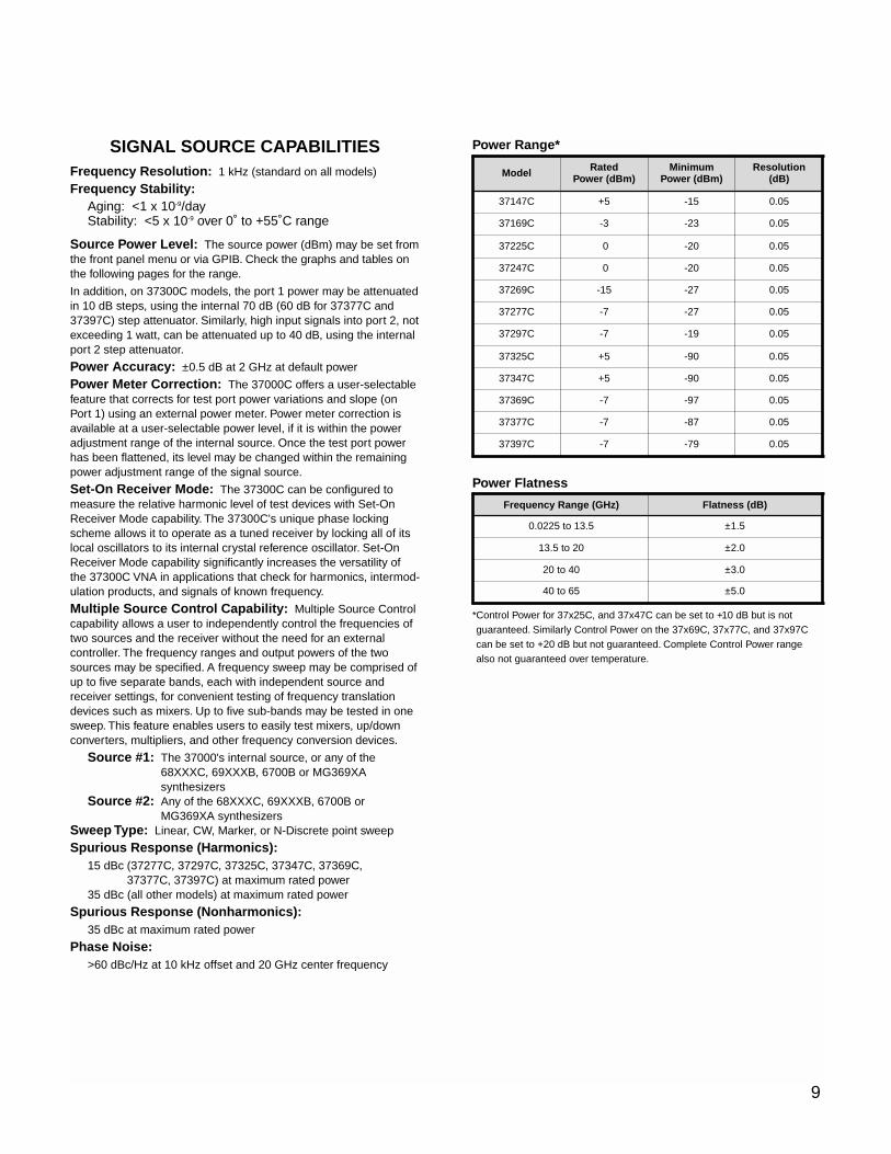
SIGNAL SOURCE CAPABILITIESFrequency Resolution: 1 kHz (standard on all models)
Frequency Stability:Aging: <1 x 10⁻⁹/dayStability: <5 x 10⁻⁹ over 0˚ to +55˚C range
Source Power Level: The source power (dBm) may be set fromthe front panel menu or via GPIB. Check the graphs and tables onthe following pages for the range.
In addition, on 37300C models, the port 1 power may be attenuatedin 10 dB steps, using the internal 70 dB (60 dB for 37377C and37397C) step attenuator. Similarly, high input signals into port 2, notexceeding 1 watt, can be attenuated up to 40 dB, using the internalport 2 step attenuator.
Power Accuracy: ±0.5 dB at 2 GHz at default power
Power Meter Correction: The 37000C offers a user-selectablefeature that corrects for test port power variations and slope (onPort 1) using an external power meter. Power meter correction isavailable at a user-selectable power level, if it is within the poweradjustment range of the internal source. Once the test port powerhas been flattened, its level may be changed within the remainingpower adjustment range of the signal source.
Set-On Receiver Mode: The 37300C can be configured tomeasure the relative harmonic level of test devices with Set-OnReceiver Mode capability. The 37300C's unique phase lockingscheme allows it to operate as a tuned receiver by locking all of itslocal oscillators to its internal crystal reference oscillator. Set-OnReceiver Mode capability significantly increases the versatility ofthe 37300C VNA in applications that check for harmonics, intermod-ulation products, and signals of known frequency.
Multiple Source Control Capability: Multiple Source Controlcapability allows a user to independently control the frequencies oftwo sources and the receiver without the need for an externalcontroller. The frequency ranges and output powers of the twosources may be specified. A frequency sweep may be comprised ofup to five separate bands, each with independent source andreceiver settings, for convenient testing of frequency translationdevices such as mixers. Up to five sub-bands may be tested in onesweep. This feature enables users to easily test mixers, up/downconverters, multipliers, and other frequency conversion devices.
Source #1: The 37000's internal source, or any of the68XXXC, 69XXXB, 6700B or MG369XAsynthesizers
Source #2: Any of the 68XXXC, 69XXXB, 6700B orMG369XA synthesizers
Sweep Type: Linear, CW, Marker, or N-Discrete point sweep
Spurious Response (Harmonics):15 dBc (37277C, 37297C, 37325C, 37347C, 37369C,
37377C, 37397C) at maximum rated power35 dBc (all other models) at maximum rated power
Spurious Response (Nonharmonics):35 dBc at maximum rated power
Phase Noise:>60 dBc/Hz at 10 kHz offset and 20 GHz center frequency
Power Range*
Power Flatness
*Control Power for 37x25C, and 37x47C can be set to +10 dB but is notguaranteed. Similarly Control Power on the 37x69C, 37x77C, and 37x97Ccan be set to +20 dB but not guaranteed. Complete Control Power rangealso not guaranteed over temperature.
j9 Frequency Range (GHz)
9
0.0225 to 13.5 ±1.5
13.5 to 20 ±2.0
20 to 40 ±3.0
40 to 65 ±5.0
Model Rated Power (dBm)
Minimum Power (dBm)
Resolution (dB)
37147C +5 -15 0.05
37169C -3 -23 0.05
37225C 0 -20 0.05
37247C 0 -20 0.05
37269C -15 -27 0.05
37277C -7 -27 0.05
37297C -7 -19 0.05
37325C +5 -90 0.05
37347C +5 -90 0.05
37369C -7 -97 0.05
37377C -7 -87 0.05
37397C -7 -79 0.05
Flatness (dB)
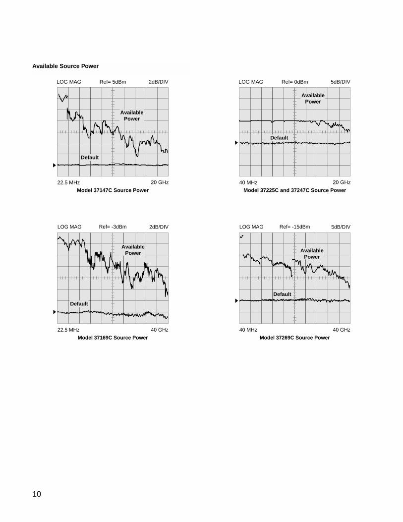
10
LOG MAG 5dB/DIVRef= 0dBm
40 MHz 20 GHz
Default
AvailablePower
Model 37225C and 37247C Source Power
LOG MAG Ref= -15dBm 5dB/DIV
40 MHz 40 GHz
Model 37269C Source Power
AvailablePower
Default
LOG MAG 2dB/DIVRef= 5dBm
22.5 MHz 20 GHz
Default
AvailablePower
Model 37147C Source Power
LOG MAG Ref= -3dBm 2dB/DIV
22.5 MHz 40 GHz
Model 37169C Source Power
AvailablePower
Default
Available Source Power
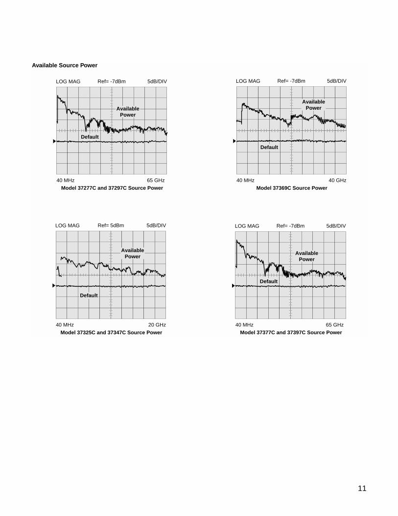
11
Model 37325C and 37347C Source Power40 MHz 20 GHz
LOG MAG 5dB/DIVRef= 5dBm
AvailablePower
Default
40 MHz 40 GHz
Model 37369C Source Power
LOG MAG 5dB/DIVRef= -7dBm
AvailablePower
Default
40 MHz 65 GHz
Model 37377C and 37397C Source Power
LOG MAG 5dB/DIVRef= -7dBm
AvailablePower
Default
Available Source Power
40 MHz 65 GHz
Model 37277C and 37297C Source Power
LOG MAG 5dB/DIVRef= -7dBm
AvailablePower
Default
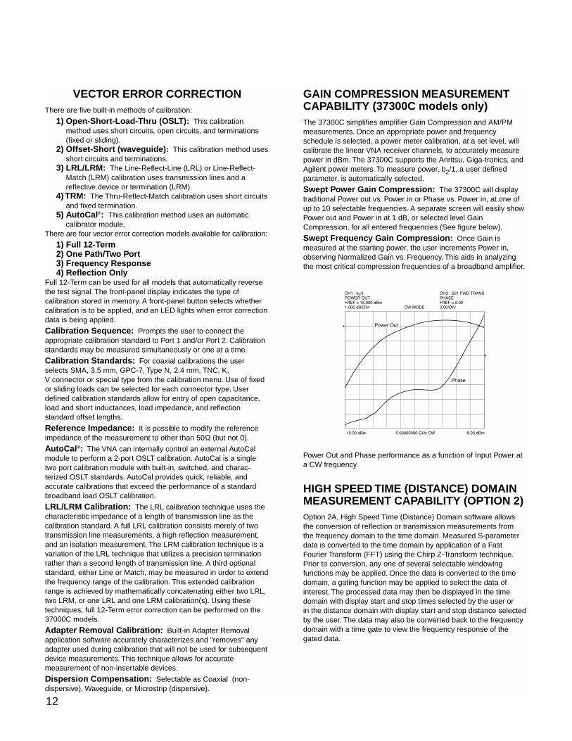
12
VECTOR ERROR CORRECTIONThere are five built-in methods of calibration:
1) Open-Short-Load-Thru (OSLT): This calibrationmethod uses short circuits, open circuits, and terminations(fixed or sliding).
2) Offset-Short (waveguide): This calibration method usesshort circuits and terminations.
3) LRL/LRM: The Line-Reflect-Line (LRL) or Line-Reflect-Match (LRM) calibration uses transmission lines and areflective device or termination (LRM).
4) TRM: The Thru-Reflect-Match calibration uses short circuitsand fixed termination.
5) AutoCal®: This calibration method uses an automaticcalibrator module.
There are four vector error correction models available for calibration:
1) Full 12-Term2) One Path/Two Port3) Frequency Response4) Reflection Only
Full 12-Term can be used for all models that automatically reversethe test signal. The front-panel display indicates the type ofcalibration stored in memory. A front-panel button selects whethercalibration is to be applied, and an LED lights when error correctiondata is being applied.
Calibration Sequence: Prompts the user to connect theappropriate calibration standard to Port 1 and/or Port 2. Calibrationstandards may be measured simultaneously or one at a time.
Calibration Standards: For coaxial calibrations the userselects SMA, 3.5 mm, GPC-7, Type N, 2.4 mm, TNC, K,V connector or special type from the calibration menu. Use of fixedor sliding loads can be selected for each connector type. Userdefined calibration standards allow for entry of open capacitance,load and short inductances, load impedance, and reflectionstandard offset lengths.
Reference Impedance: It is possible to modify the referenceimpedance of the measurement to other than 50Ω (but not 0).
AutoCal®: The VNA can internally control an external AutoCalmodule to perform a 2-port OSLT calibration. AutoCal is a singletwo port calibration module with built-in, switched, and charac-terized OSLT standards. AutoCal provides quick, reliable, andaccurate calibrations that exceed the performance of a standardbroadband load OSLT calibration.
LRL/LRM Calibration: The LRL calibration technique uses thecharacteristic impedance of a length of transmission line as thecalibration standard. A full LRL calibration consists merely of twotransmission line measurements, a high reflection measurement,and an isolation measurement. The LRM calibration technique is avariation of the LRL technique that utilizes a precision terminationrather than a second length of transmission line. A third optionalstandard, either Line or Match, may be measured in order to extendthe frequency range of the calibration. This extended calibrationrange is achieved by mathematically concatenating either two LRL,two LRM, or one LRL and one LRM calibration(s). Using thesetechniques, full 12-Term error correction can be performed on the37000C models.
Adapter Removal Calibration: Built-in Adapter Removalapplication software accurately characterizes and "removes" anyadapter used during calibration that will not be used for subsequentdevice measurements. This technique allows for accuratemeasurement of non-insertable devices.
Dispersion Compensation: Selectable as Coaxial (non-dispersive), Waveguide, or Microstrip (dispersive).
GAIN COMPRESSION MEASUREMENTCAPABILITY (37300C models only)The 37300C simplifies amplifier Gain Compression and AM/PMmeasurements. Once an appropriate power and frequencyschedule is selected, a power meter calibration, at a set level, willcalibrate the linear VNA receiver channels, to accurately measurepower in dBm. The 37300C supports the Anritsu, Giga-tronics, andAgilent power meters. To measure power, b2/1, a user definedparameter, is automatically selected.
Swept Power Gain Compression: The 37300C will displaytraditional Power out vs. Power in or Phase vs. Power in, at one ofup to 10 selectable frequencies. A separate screen will easily showPower out and Power in at 1 dB, or selected level GainCompression, for all entered frequencies (See figure below).
Swept Frequency Gain Compression: Once Gain ismeasured at the starting power, the user increments Power in,observing Normalized Gain vs. Frequency. This aids in analyzingthe most critical compression frequencies of a broadband amplifier.
Power Out and Phase performance as a function of Input Power ata CW frequency.
HIGH SPEED TIME (DISTANCE) DOMAINMEASUREMENT CAPABILITY (OPTION 2)Option 2A, High Speed Time (Distance) Domain software allowsthe conversion of reflection or transmission measurements fromthe frequency domain to the time domain. Measured S-parameterdata is converted to the time domain by application of a FastFourier Transform (FFT) using the Chirp Z-Transform technique.Prior to conversion, any one of several selectable windowingfunctions may be applied. Once the data is converted to the timedomain, a gating function may be applied to select the data ofinterest. The processed data may then be displayed in the timedomain with display start and stop times selected by the user orin the distance domain with display start and stop distance selectedby the user. The data may also be converted back to the frequencydomain with a time gate to view the frequency response of thegated data.
-12.00 dBm 8.00 dBm5.00000000 GHz CW
CH1 : b2/1
POWER OUT
REF = 15.000 dBm
1.000 dB/DIV CW MODE
CH3 : S21 FWD TRANS
PHASE
REF = 5.00
2.00/DIV
Phase
Power Out
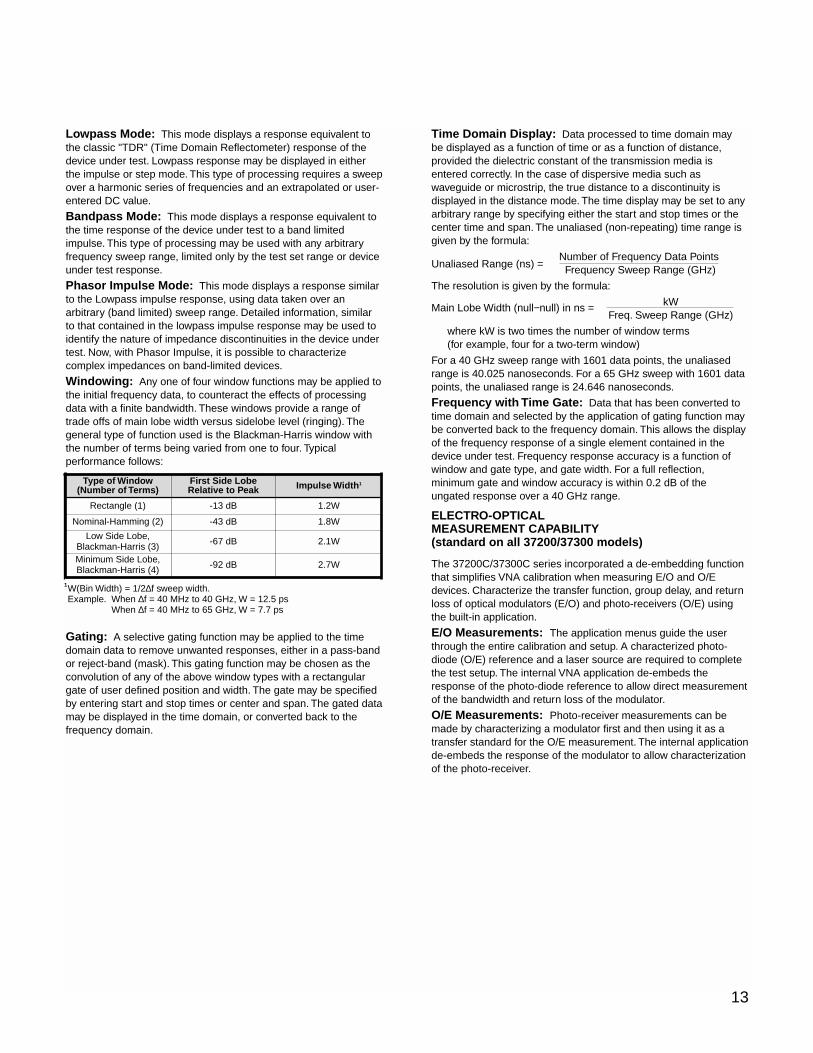
13
Lowpass Mode: This mode displays a response equivalent tothe classic "TDR" (Time Domain Reflectometer) response of thedevice under test. Lowpass response may be displayed in eitherthe impulse or step mode. This type of processing requires a sweepover a harmonic series of frequencies and an extrapolated or user-entered DC value.
Bandpass Mode: This mode displays a response equivalent tothe time response of the device under test to a band limitedimpulse. This type of processing may be used with any arbitraryfrequency sweep range, limited only by the test set range or deviceunder test response.
Phasor Impulse Mode: This mode displays a response similarto the Lowpass impulse response, using data taken over anarbitrary (band limited) sweep range. Detailed information, similarto that contained in the lowpass impulse response may be used toidentify the nature of impedance discontinuities in the device undertest. Now, with Phasor Impulse, it is possible to characterizecomplex impedances on band-limited devices.
Windowing: Any one of four window functions may be applied tothe initial frequency data, to counteract the effects of processingdata with a finite bandwidth. These windows provide a range oftrade offs of main lobe width versus sidelobe level (ringing). Thegeneral type of function used is the Blackman-Harris window withthe number of terms being varied from one to four. Typicalperformance follows:
Gating: A selective gating function may be applied to the timedomain data to remove unwanted responses, either in a pass-bandor reject-band (mask). This gating function may be chosen as theconvolution of any of the above window types with a rectangulargate of user defined position and width. The gate may be specifiedby entering start and stop times or center and span. The gated datamay be displayed in the time domain, or converted back to thefrequency domain.
Time Domain Display: Data processed to time domain maybe displayed as a function of time or as a function of distance,provided the dielectric constant of the transmission media isentered correctly. In the case of dispersive media such aswaveguide or microstrip, the true distance to a discontinuity isdisplayed in the distance mode. The time display may be set to anyarbitrary range by specifying either the start and stop times or thecenter time and span. The unaliased (non-repeating) time range isgiven by the formula:
Number of Frequency Data PointsUnaliased Range (ns) = Frequency Sweep Range (GHz)
The resolution is given by the formula:
Main Lobe Width (null−null) in ns = kWFreq. Sweep Range (GHz)
where kW is two times the number of window terms (for example, four for a two-term window)
For a 40 GHz sweep range with 1601 data points, the unaliasedrange is 40.025 nanoseconds. For a 65 GHz sweep with 1601 datapoints, the unaliased range is 24.646 nanoseconds.
Frequency with Time Gate: Data that has been converted totime domain and selected by the application of gating function maybe converted back to the frequency domain. This allows the displayof the frequency response of a single element contained in thedevice under test. Frequency response accuracy is a function ofwindow and gate type, and gate width. For a full reflection,minimum gate and window accuracy is within 0.2 dB of theungated response over a 40 GHz range.
ELECTRO-OPTICALMEASUREMENT CAPABILITY(standard on all 37200/37300 models)
The 37200C/37300C series incorporated a de-embedding functionthat simplifies VNA calibration when measuring E/O and O/Edevices. Characterize the transfer function, group delay, and returnloss of optical modulators (E/O) and photo-receivers (O/E) usingthe built-in application.
E/O Measurements: The application menus guide the userthrough the entire calibration and setup. A characterized photo-diode (O/E) reference and a laser source are required to completethe test setup. The internal VNA application de-embeds theresponse of the photo-diode reference to allow direct measurementof the bandwidth and return loss of the modulator.
O/E Measurements: Photo-receiver measurements can bemade by characterizing a modulator first and then using it as atransfer standard for the O/E measurement. The internal applicationde-embeds the response of the modulator to allow characterizationof the photo-receiver.
Type of Window(Number of Terms)
First Side Lobe Relative to Peak
Rectangle (1) -13 dB
Nominal-Hamming (2) -43 dB
Low Side Lobe,Blackman-Harris (3) -67 dB
Minimum Side Lobe,Blackman-Harris (4) -92 dB 2.7W
2.1W
1.8W
1.2W
Impulse Width1
1W(Bin Width) = 1/2∆f sweep width.Example. When ∆f = 40 MHz to 40 GHz, W = 12.5 ps
When ∆f = 40 MHz to 65 GHz, W = 7.7 ps
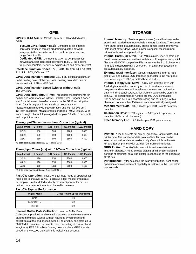
14
GPIBGPIB INTERFACES: 2 Ports, system GPIB and dedicatedGPIB
System GPIB (IEEE-488.2): Connects to an externalcontroller for use in remote programming of the networkanalyzer. Address can be set from the front panel and canrange from 1 to 30.Dedicated GPIB: Connects to external peripherals fornetwork analyzer controlled operations (e.g., GPIB plotters,frequency counters, frequency synthesizers and power meters).
Interface Function Codes: SH1, AH1, T6, TE0, L4, LE0, SR1,RL1, PP1, DT1, DC0, and C0.
GPIB Data Transfer Formats: ASCII, 32-bit floating point, or64-bit floating point. 32-bit and 64-bit floating point data can betransferred with LSB or MSB first.
GPIB Data Transfer Speed (with or without cal):150 kbyte/sec
GPIB Data Throughput Time: Throughput measurements forboth tables were made as follows: start the timer, trigger a sweep,wait for a full sweep, transfer data across the GPIB and stop thetimer. Data throughput times are shown separately formeasurements made without calibration and with full two-port,12-Term calibration. Measurement conditions: 40 MHz to 20 GHzsweep, single channel, log magnitude display, 10 kHz IF bandwidth,and output final data.
Throughput Times (ms) without Correction (typical)
Throughput Times (ms) with 12-Term Correction (typical)
Fast CW Operation: Fast CW is an ideal mode of operation forrapid data taking over GPIB. To achieve a fast measurement ratethe display is not updated and only the raw S-parameter or user-defined parameter of the active channel is measured.
Fast CW Typical Performance
Internal Buffer Data Collection: Internal Buffer DataCollection is provided to allow saving active channel measurementdata from multiple sweeps without having to synchronize andcollect data at the end of each sweep. The 37000C can store up to50,000 data point measurements, each consisting of two (real andimaginary) IEEE 754 4-byte floating point numbers. GPIB transferspeed for the 50,000 data points is typically 2.2 seconds.
STORAGE
Internal Memory: Ten front panel states (no calibration) can bestored and recalled from non-volatile memory locations. The currentfront panel setup is automatically stored in non-volatile memory atinstrument power-down. When power is applied, the instrumentreturns to its last front panel setup.
Internal Hard Disk Drive: 340 MB mininum, used to store andrecall measurement and calibration data and front-panel setups. Allfiles are MS-DOS® compatible. File names can be 1 to 8 characterslong, and must begin with a character, not a number. Extensionsare automatically assigned.
External SCSI Interface: Option 4 deletes the internal harddisk drive, and adds a SCSI Interface connector to the rear panelfor connecting a SCSI-2 formatted hard disk drive.
Internal Floppy Disk Drive: A 3.5-inch diskette drive with1.44 Mbytes formatted capacity is used to load measurementprograms and to store and recall measurement and calibrationdata and front-panel setups. Measurement data can be stored intext, S2P or bitmap format. All files are MS-DOS compatible.File names can be 1 to 8 characters long and must begin with acharacter, not a number. Extensions are automatically assigned.
Measurement Data: 102.8 kbytes per 1601 point S-parameterdata file.
Calibration Data: 187.3 kbytes per 1601 point S-parameterdata file (12-Term cal plus setup).
Trace Memory File: 12.8 kbytes per 1601 point channel.
HARD COPYPrinter: A menu selects full screen, graphical, tabular data, andprinter type. The number of data points of tabular data can beselected as well as data at markers only. Compatible with mostHP and Epson printers with parallel (Centronics) interfaces.
GPIB Plotter: The 37000 is compatible with most HP andTektronix plotters. A menu selects plotting of full or user-selectedportions of graphical data. The plotter is connected to the dedicatedGPIB bus.
Performance: After selecting the Start Print button, front paneloperation and measurement capability is restored to the user withintwo seconds.
Data Format 3 Points* 101 Points 401 Points 1601 Points
32 Bit 150 500 1200 3600
64 Bit 150 500 1200 3600
ASCII 150 600 1500 4400
3 Points* 101 Points 401 Points 1601 Points
190 950 2300 6900
190 950 2300 6900
190 1000 2500 7400
*3 data point sweeps taken at 2, 4, and 6 GHz
Trigger Mode Measurement Speed (ms/point)
GPIB 1.5
External TTL 1.2
Internal 0.8
Data Format
32 Bit
64 Bit
ASCII
*3 data point sweeps taken at 2, 4, and 6 GHz
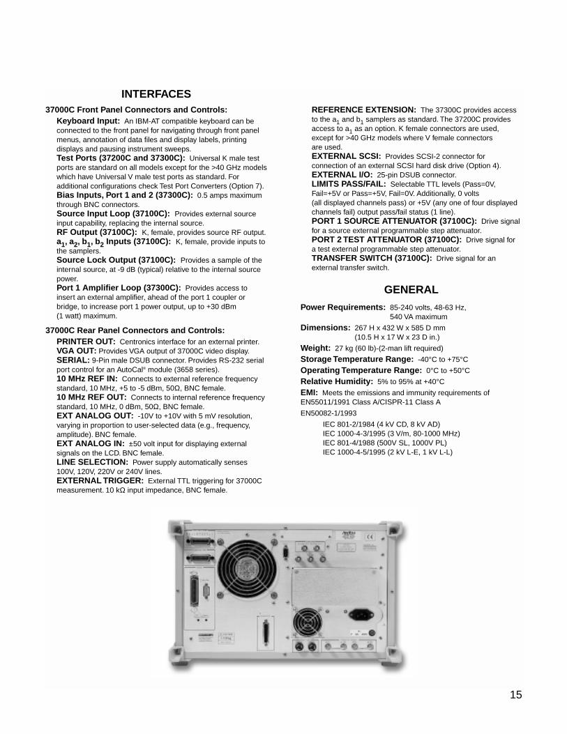
15
INTERFACES37000C Front Panel Connectors and Controls:
Keyboard Input: An IBM-AT compatible keyboard can beconnected to the front panel for navigating through front panelmenus, annotation of data files and display labels, printingdisplays and pausing instrument sweeps.Test Ports (37200C and 37300C): Universal K male testports are standard on all models except for the >40 GHz modelswhich have Universal V male test ports as standard. Foradditional configurations check Test Port Converters (Option 7).Bias Inputs, Port 1 and 2 (37300C): 0.5 amps maximumthrough BNC connectors.Source Input Loop (37100C): Provides external sourceinput capability, replacing the internal source.RF Output (37100C): K, female, provides source RF output.a1, a2, b1, b2 Inputs (37100C): K, female, provide inputs tothe samplers.Source Lock Output (37100C): Provides a sample of theinternal source, at -9 dB (typical) relative to the internal sourcepower.Port 1 Amplifier Loop (37300C): Provides access toinsert an external amplifier, ahead of the port 1 coupler orbridge, to increase port 1 power output, up to +30 dBm(1 watt) maximum.
37000C Rear Panel Connectors and Controls:PRINTER OUT: Centronics interface for an external printer.VGA OUT: Provides VGA output of 37000C video display.SERIAL: 9-Pin male DSUB connector. Provides RS-232 serialport control for an AutoCal® module (3658 series).10 MHz REF IN: Connects to external reference frequencystandard, 10 MHz, +5 to -5 dBm, 50Ω, BNC female.10 MHz REF OUT: Connects to internal reference frequencystandard, 10 MHz, 0 dBm, 50Ω, BNC female.EXT ANALOG OUT: -10V to +10V with 5 mV resolution,varying in proportion to user-selected data (e.g., frequency,amplitude). BNC female.EXT ANALOG IN: ±50 volt input for displaying externalsignals on the LCD. BNC female.LINE SELECTION: Power supply automatically senses100V, 120V, 220V or 240V lines.EXTERNAL TRIGGER: External TTL triggering for 37000Cmeasurement. 10 kΩ input impedance, BNC female.
REFERENCE EXTENSION: The 37300C provides accessto the a1 and b1 samplers as standard. The 37200C providesaccess to a1 as an option. K female connectors are used,except for >40 GHz models where V female connectorsare used.EXTERNAL SCSI: Provides SCSI-2 connector forconnection of an external SCSI hard disk drive (Option 4).EXTERNAL I/O: 25-pin DSUB connector.LIMITS PASS/FAIL: Selectable TTL levels (Pass=0V,Fail=+5V or Pass=+5V, Fail=0V. Additionally, 0 volts(all displayed channels pass) or +5V (any one of four displayedchannels fail) output pass/fail status (1 line).PORT 1 SOURCE ATTENUATOR (37100C): Drive signalfor a source external programmable step attenuator.PORT 2 TEST ATTENUATOR (37100C): Drive signal fora test external programmable step attenuator.TRANSFER SWITCH (37100C): Drive signal for anexternal transfer switch.
GENERAL
Power Requirements: 85-240 volts, 48-63 Hz,540 VA maximum
Dimensions: 267 H x 432 W x 585 D mm (10.5 H x 17 W x 23 D in.)
Weight: 27 kg (60 lb)-(2-man lift required)
Storage Temperature Range: -40°C to +75°C
Operating Temperature Range: 0°C to +50°C
Relative Humidity: 5% to 95% at +40°C
EMI: Meets the emissions and immunity requirements ofEN55011/1991 Class A/CISPR-11 Class A
EN50082-1/1993
IEC 801-2/1984 (4 kV CD, 8 kV AD)IEC 1000-4-3/1995 (3 V/m, 80-1000 MHz)IEC 801-4/1988 (500V SL, 1000V PL)IEC 1000-4-5/1995 (2 kV L-E, 1 kV L-L)

©Anritsu January 2003; Rev: C 11410-00247Data subject to change without notice 37100C/37200C/37300C Vector Network Analyzers Technical Data Sheet
Microwave Measurements Division • 490 Jarvis Drive • Morgan Hill, CA 95037-2809http://www.us.anritsu.com • FAX (408) 778-0239
Sales Centers:United States (800) ANRITSUCanada (800) ANRITSUSouth America 55 (21) 286-9141
Sales Centers:Europe 44 (0) 1582 433433Japan 81 (03) 3446-1111Asia-Pacific 65-2822400
LRL/LRM-Calibration method of Rohde & Schwarz, GermanyGPC−7 is a registered trademark of Amphenol Corporation.K Connector and V Connector are registered trademarks of Anritsu Company.AutoCal is a registered trademark of Anritsu Company.
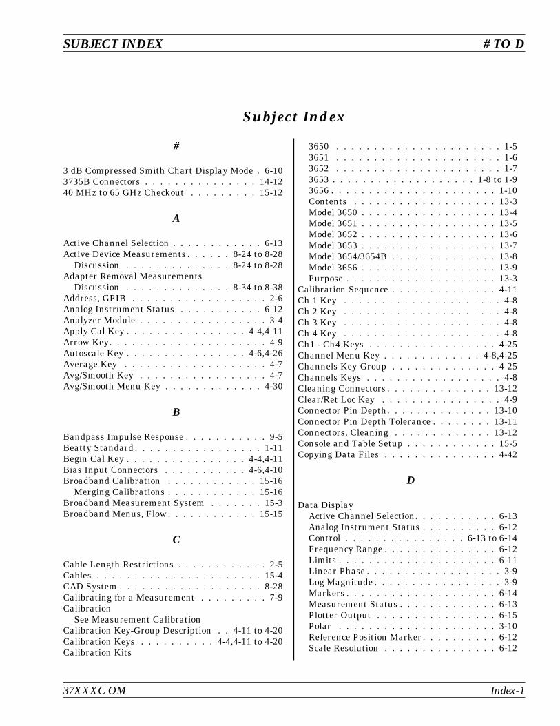
Subject Index
#
3 dB Compressed Smith Chart Display Mode . 6-103735B Connectors . . . . . . . . . . . . . . . 14-1240 MHz to 65 GHz Checkout . . . . . . . . . 15-12
A
Active Channel Selection . . . . . . . . . . . . 6-13Active Device Measurements . . . . . . 8-24 to 8-28
Discussion . . . . . . . . . . . . . . 8-24 to 8-28Adapter Removal Measurements
Discussion . . . . . . . . . . . . . . 8-34 to 8-38Address, GPIB . . . . . . . . . . . . . . . . . . 2-6Analog Instrument Status . . . . . . . . . . . 6-12Analyzer Module . . . . . . . . . . . . . . . . . 3-4Apply Cal Key . . . . . . . . . . . . . . . . 4-4,4-11Arrow Key. . . . . . . . . . . . . . . . . . . . . 4-9Autoscale Key . . . . . . . . . . . . . . . . 4-6,4-26Average Key . . . . . . . . . . . . . . . . . . . 4-7Avg/Smooth Key . . . . . . . . . . . . . . . . . 4-7Avg/Smooth Menu Key . . . . . . . . . . . . . 4-30
B
Bandpass Impulse Response . . . . . . . . . . . 9-5Beatty Standard. . . . . . . . . . . . . . . . . 1-11Begin Cal Key . . . . . . . . . . . . . . . . 4-4,4-11Bias Input Connectors . . . . . . . . . . . 4-6,4-10Broadband Calibration . . . . . . . . . . . . 15-16
Merging Calibrations . . . . . . . . . . . . 15-16Broadband Measurement System . . . . . . . 15-3Broadband Menus, Flow. . . . . . . . . . . . 15-15
C
Cable Length Restrictions . . . . . . . . . . . . 2-5Cables . . . . . . . . . . . . . . . . . . . . . . 15-4CAD System . . . . . . . . . . . . . . . . . . . 8-28Calibrating for a Measurement . . . . . . . . . 7-9Calibration
See Measurement CalibrationCalibration Key-Group Description . . 4-11 to 4-20Calibration Keys . . . . . . . . . . 4-4,4-11 to 4-20Calibration Kits
3650 . . . . . . . . . . . . . . . . . . . . . . 1-53651 . . . . . . . . . . . . . . . . . . . . . . 1-63652 . . . . . . . . . . . . . . . . . . . . . . 1-73653 . . . . . . . . . . . . . . . . . . . 1-8 to 1-93656 . . . . . . . . . . . . . . . . . . . . . . 1-10Contents . . . . . . . . . . . . . . . . . . . 13-3Model 3650 . . . . . . . . . . . . . . . . . . 13-4Model 3651 . . . . . . . . . . . . . . . . . . 13-5Model 3652 . . . . . . . . . . . . . . . . . . 13-6Model 3653 . . . . . . . . . . . . . . . . . . 13-7Model 3654/3654B . . . . . . . . . . . . . . 13-8Model 3656 . . . . . . . . . . . . . . . . . . 13-9Purpose . . . . . . . . . . . . . . . . . . . . 13-3
Calibration Sequence . . . . . . . . . . . . . . 4-11Ch 1 Key . . . . . . . . . . . . . . . . . . . . . 4-8Ch 2 Key . . . . . . . . . . . . . . . . . . . . . 4-8Ch 3 Key . . . . . . . . . . . . . . . . . . . . . 4-8Ch 4 Key . . . . . . . . . . . . . . . . . . . . . 4-8Ch1 - Ch4 Keys . . . . . . . . . . . . . . . . . 4-25Channel Menu Key . . . . . . . . . . . . . 4-8,4-25Channels Key-Group . . . . . . . . . . . . . . 4-25Channels Keys . . . . . . . . . . . . . . . . . . 4-8Cleaning Connectors . . . . . . . . . . . . . . 13-12Clear/Ret Loc Key . . . . . . . . . . . . . . . . 4-9Connector Pin Depth. . . . . . . . . . . . . . 13-10Connector Pin Depth Tolerance . . . . . . . . 13-11Connectors, Cleaning . . . . . . . . . . . . . 13-12Console and Table Setup . . . . . . . . . . . . 15-5Copying Data Files . . . . . . . . . . . . . . . 4-42
D
Data DisplayActive Channel Selection. . . . . . . . . . . 6-13Analog Instrument Status . . . . . . . . . . 6-12Control . . . . . . . . . . . . . . . . 6-13 to 6-14Frequency Range . . . . . . . . . . . . . . . 6-12Limits . . . . . . . . . . . . . . . . . . . . . 6-11Linear Phase . . . . . . . . . . . . . . . . . . 3-9Log Magnitude . . . . . . . . . . . . . . . . . 3-9Markers . . . . . . . . . . . . . . . . . . . . 6-14Measurement Status . . . . . . . . . . . . . 6-13Plotter Output . . . . . . . . . . . . . . . . 6-15Polar . . . . . . . . . . . . . . . . . . . . . 3-10Reference Position Marker. . . . . . . . . . 6-12Scale Resolution . . . . . . . . . . . . . . . 6-12
SUBJECT INDEX # TO D
37XXXC OM Index-1
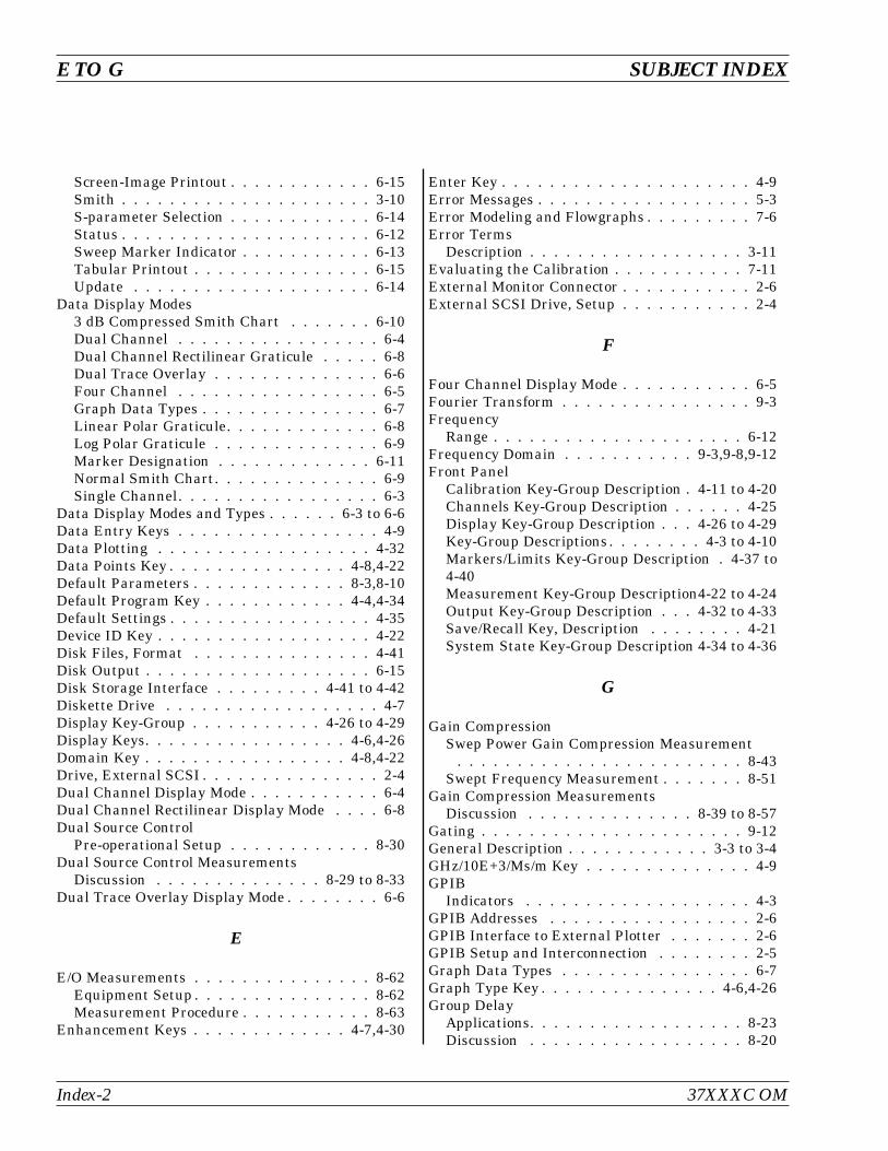
Screen-Image Printout . . . . . . . . . . . . 6-15Smith . . . . . . . . . . . . . . . . . . . . . 3-10S-parameter Selection . . . . . . . . . . . . 6-14Status . . . . . . . . . . . . . . . . . . . . . 6-12Sweep Marker Indicator . . . . . . . . . . . 6-13Tabular Printout . . . . . . . . . . . . . . . 6-15Update . . . . . . . . . . . . . . . . . . . . 6-14
Data Display Modes3 dB Compressed Smith Chart . . . . . . . 6-10Dual Channel . . . . . . . . . . . . . . . . . 6-4Dual Channel Rectilinear Graticule . . . . . 6-8Dual Trace Overlay . . . . . . . . . . . . . . 6-6Four Channel . . . . . . . . . . . . . . . . . 6-5Graph Data Types . . . . . . . . . . . . . . . 6-7Linear Polar Graticule. . . . . . . . . . . . . 6-8Log Polar Graticule . . . . . . . . . . . . . . 6-9Marker Designation . . . . . . . . . . . . . 6-11Normal Smith Chart. . . . . . . . . . . . . . 6-9Single Channel. . . . . . . . . . . . . . . . . 6-3
Data Display Modes and Types . . . . . . 6-3 to 6-6Data Entry Keys . . . . . . . . . . . . . . . . . 4-9Data Plotting . . . . . . . . . . . . . . . . . . 4-32Data Points Key . . . . . . . . . . . . . . . 4-8,4-22Default Parameters . . . . . . . . . . . . . 8-3,8-10Default Program Key . . . . . . . . . . . . 4-4,4-34Default Settings . . . . . . . . . . . . . . . . . 4-35Device ID Key . . . . . . . . . . . . . . . . . . 4-22Disk Files, Format . . . . . . . . . . . . . . . 4-41Disk Output . . . . . . . . . . . . . . . . . . . 6-15Disk Storage Interface . . . . . . . . . 4-41 to 4-42Diskette Drive . . . . . . . . . . . . . . . . . . 4-7Display Key-Group . . . . . . . . . . . 4-26 to 4-29Display Keys. . . . . . . . . . . . . . . . . 4-6,4-26Domain Key . . . . . . . . . . . . . . . . . 4-8,4-22Drive, External SCSI . . . . . . . . . . . . . . . 2-4Dual Channel Display Mode . . . . . . . . . . . 6-4Dual Channel Rectilinear Display Mode . . . . 6-8Dual Source Control
Pre-operational Setup . . . . . . . . . . . . 8-30Dual Source Control Measurements
Discussion . . . . . . . . . . . . . . 8-29 to 8-33Dual Trace Overlay Display Mode . . . . . . . . 6-6
E
E/O Measurements . . . . . . . . . . . . . . . 8-62Equipment Setup . . . . . . . . . . . . . . . 8-62Measurement Procedure . . . . . . . . . . . 8-63
Enhancement Keys . . . . . . . . . . . . . 4-7,4-30
Enter Key . . . . . . . . . . . . . . . . . . . . . 4-9Error Messages . . . . . . . . . . . . . . . . . . 5-3Error Modeling and Flowgraphs . . . . . . . . . 7-6Error Terms
Description . . . . . . . . . . . . . . . . . . 3-11Evaluating the Calibration . . . . . . . . . . . 7-11External Monitor Connector . . . . . . . . . . . 2-6External SCSI Drive, Setup . . . . . . . . . . . 2-4
F
Four Channel Display Mode . . . . . . . . . . . 6-5Fourier Transform . . . . . . . . . . . . . . . . 9-3Frequency
Range . . . . . . . . . . . . . . . . . . . . . 6-12Frequency Domain . . . . . . . . . . . 9-3,9-8,9-12Front Panel
Calibration Key-Group Description . 4-11 to 4-20Channels Key-Group Description . . . . . . 4-25Display Key-Group Description . . . 4-26 to 4-29Key-Group Descriptions. . . . . . . . 4-3 to 4-10Markers/Limits Key-Group Description . 4-37 to4-40Measurement Key-Group Description4-22 to 4-24Output Key-Group Description . . . 4-32 to 4-33Save/Recall Key, Description . . . . . . . . 4-21System State Key-Group Description 4-34 to 4-36
G
Gain CompressionSwep Power Gain Compression Measurement
. . . . . . . . . . . . . . . . . . . . . . . . 8-43Swept Frequency Measurement . . . . . . . 8-51
Gain Compression MeasurementsDiscussion . . . . . . . . . . . . . . 8-39 to 8-57
Gating . . . . . . . . . . . . . . . . . . . . . . 9-12General Description . . . . . . . . . . . . 3-3 to 3-4GHz/10E+3/Ms/m Key . . . . . . . . . . . . . . 4-9GPIB
Indicators . . . . . . . . . . . . . . . . . . . 4-3GPIB Addresses . . . . . . . . . . . . . . . . . 2-6GPIB Interface to External Plotter . . . . . . . 2-6GPIB Setup and Interconnection . . . . . . . . 2-5Graph Data Types . . . . . . . . . . . . . . . . 6-7Graph Type Key . . . . . . . . . . . . . . . 4-6,4-26Group Delay
Applications. . . . . . . . . . . . . . . . . . 8-23Discussion . . . . . . . . . . . . . . . . . . 8-20
Index-2 37XXXC OM
E TO G SUBJECT INDEX
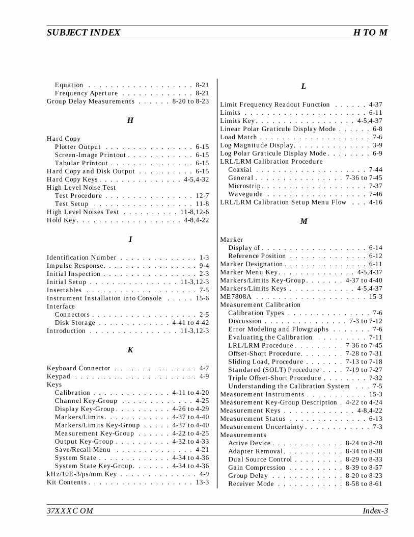
Equation . . . . . . . . . . . . . . . . . . . 8-21Frequency Aperture . . . . . . . . . . . . . 8-21
Group Delay Measurements . . . . . . 8-20 to 8-23
H
Hard CopyPlotter Output . . . . . . . . . . . . . . . . 6-15Screen-Image Printout . . . . . . . . . . . . 6-15Tabular Printout . . . . . . . . . . . . . . . 6-15
Hard Copy and Disk Output . . . . . . . . . . 6-15Hard Copy Keys . . . . . . . . . . . . . . . 4-5,4-32High Level Noise Test
Test Procedure . . . . . . . . . . . . . . . . 12-7Test Setup . . . . . . . . . . . . . . . . . . 11-8
High Level Noises Test . . . . . . . . . . 11-8,12-6Hold Key. . . . . . . . . . . . . . . . . . . 4-8,4-22
I
Identification Number . . . . . . . . . . . . . . 1-3Impulse Response. . . . . . . . . . . . . . . . . 9-4Initial Inspection . . . . . . . . . . . . . . . . . 2-3Initial Setup . . . . . . . . . . . . . . . . 11-3,12-3Insertables . . . . . . . . . . . . . . . . . . . . 7-5Instrument Installation into Console . . . . . 15-6Interface
Connectors . . . . . . . . . . . . . . . . . . . 2-5Disk Storage . . . . . . . . . . . . . 4-41 to 4-42
Introduction . . . . . . . . . . . . . . . . 11-3,12-3
K
Keyboard Connector . . . . . . . . . . . . . . . 4-7Keypad . . . . . . . . . . . . . . . . . . . . . . 4-9Keys
Calibration . . . . . . . . . . . . . . 4-11 to 4-20Channel Key-Group . . . . . . . . . . . . . 4-25Display Key-Group . . . . . . . . . . 4-26 to 4-29Markers/Limits. . . . . . . . . . . . 4-37 to 4-40Markers/Limits Key-Group . . . . . 4-37 to 4-40Measurement Key-Group . . . . . . 4-22 to 4-25Output Key-Group . . . . . . . . . . 4-32 to 4-33Save/Recall Menu . . . . . . . . . . . . . . 4-21System State . . . . . . . . . . . . . 4-34 to 4-36System State Key-Group. . . . . . . 4-34 to 4-36
kHz/10E-3/ps/mm Key . . . . . . . . . . . . . . 4-9Kit Contents . . . . . . . . . . . . . . . . . . . 13-3
L
Limit Frequency Readout Function . . . . . . 4-37Limits . . . . . . . . . . . . . . . . . . . . . . 6-11Limits Key . . . . . . . . . . . . . . . . . . 4-5,4-37Linear Polar Graticule Display Mode . . . . . . 6-8Load Match . . . . . . . . . . . . . . . . . . . . 7-6Log Magnitude Display. . . . . . . . . . . . . . 3-9Log Polar Graticule Display Mode . . . . . . . . 6-9LRL/LRM Calibration Procedure
Coaxial . . . . . . . . . . . . . . . . . . . . 7-44General . . . . . . . . . . . . . . . . 7-36 to 7-45Microstrip . . . . . . . . . . . . . . . . . . . 7-37Waveguide . . . . . . . . . . . . . . . . . . 7-46
LRL/LRM Calibration Setup Menu Flow . . . 4-16
M
MarkerDisplay of . . . . . . . . . . . . . . . . . . . 6-14Reference Position . . . . . . . . . . . . . . 6-12
Marker Designation . . . . . . . . . . . . . . . 6-11Marker Menu Key. . . . . . . . . . . . . . 4-5,4-37Markers/Limits Key-Group. . . . . . . 4-37 to 4-40Markers/Limits Keys . . . . . . . . . . . . 4-5,4-37ME7808A . . . . . . . . . . . . . . . . . . . . 15-3Measurement Calibration
Calibration Types . . . . . . . . . . . . . . . 7-6Discussion . . . . . . . . . . . . . . . 7-3 to 7-12Error Modeling and Flowgraphs . . . . . . . 7-6Evaluating the Calibration . . . . . . . . . 7-11LRL/LRM Procedure . . . . . . . . . 7-36 to 7-45Offset-Short Procedure. . . . . . . . 7-28 to 7-31Sliding Load, Procedure . . . . . . . 7-13 to 7-18Standared (SOLT) Procedure . . . . 7-19 to 7-27Triple Offset-Short Procedure . . . . . . . . 7-32Understanding the Calibration System . . . 7-5
Measurement Instruments . . . . . . . . . . . 15-3Measurement Key-Group Description . 4-22 to 4-24Measurement Keys . . . . . . . . . . . . . 4-8,4-22Measurement Status . . . . . . . . . . . . . . 6-13Measurement Uncertainty . . . . . . . . . . . . 7-3Measurements
Active Device . . . . . . . . . . . . . 8-24 to 8-28Adapter Removal . . . . . . . . . . . 8-34 to 8-38Dual Source Control . . . . . . . . . 8-29 to 8-33Gain Compression . . . . . . . . . . 8-39 to 8-57Group Delay . . . . . . . . . . . . . 8-20 to 8-23Receiver Mode . . . . . . . . . . . . 8-58 to 8-61
SUBJECT INDEX H TO M
37XXXC OM Index-3
Time Domain. . . . . . . . . . . . . . . . . . 9-3Transmission and Reflection . . . . . 8-3 to 8-11
Mechanical Shock . . . . . . . . . . . . . . . 13-11Menu Flow
Calibration Key-Group Menus . . . 4-11 to 4-20MARKER MENU Key . . . . . . . . . . . . 4-37Save/Recall Key. . . . . . . . . . . . . . . . 4-21
Menu Key . . . . . . . . . . . . . . . . . . 4-5,4-32Menu Keys . . . . . . . . . . . . . . . . . . . . 4-9Menus
Channels Key-Group . . . . . . . . . . . . . 4-25Display Key-Group . . . . . . . . . . 4-26 to 4-29Markers/Limits Key-Group . . . . . 4-37 to 4-40Measurement Key-Group . . . . . . 4-22 to 4-24Output Key-Group . . . . . . . . . . 4-32 to 4-33System State Key-Group. . . . . . . 4-34 to 4-36
MHz/X1/ns/cm Key . . . . . . . . . . . . . . . . 4-9Microwave Load . . . . . . . . . . . . . . . . . 7-13Millimeter Wave Measurements . . . . . . . . . 1-5Millimeter Wave System
Allowable Measurements and Calibrations 14-18Allowable Module Configurations . . . . . 14-18Calibration . . . . . . . . . . . . . . . . . 14-13Controls and Connectors . . . . . . . . . . 14-11Description . . . . . . . . . . . . . . . . . . 14-3Effect of Default Program . . . . . . . . . 14-19Installation . . . . . . . . . . . . . . . . . . 14-6Measurement Capabilities . . . . . . . . . . 14-5Measurement Procedures. . . . . . . . . . 14-23Operation . . . . . . . . . . . . . . . . . . 14-14Operational Checkout-General . . . . . . . 14-25Operational Checkout-High Level Noise Test
. . . . . . . . . . . . . . . . . . . . 14-28,14-30Operational Checkout-IF Power Level Test 14-26Performance Specifications . . . . . . . . . 14-4Remote Operation . . . . . . . . . . . . . . 14-24System Performance . . . . . . . . . . . . . 14-4Test Port Characteristics . . . . . . . . . . 14-5
Model 3650 Calibration Kit . . . . . . . . . . . 13-4Model 3651 Calibration Kit . . . . . . . . . . . 13-5Model 3652 Calibration Kit . . . . . . . . . . . 13-6Model 3653 Calibration Kit . . . . . . . . . . . 13-7Model 3654/3654B Calibration Kit . . . . . . . 13-8Model 3656 Calibration Kit . . . . . . . . . . . 13-9Multiple Source Control
Control Formula . . . . . . . . . . . . . . . 8-29Operation . . . . . . . . . . . . . . . . . . . 8-31
N
Network Analyzers . . . . . . . . . . . . . . . 7-13Basics. . . . . . . . . . . . . . . . . . . . . . 3-6Description . . . . . . . . . . . . . . . . . . . 1-3Error Correction . . . . . . . . . . . . . . . 3-11Measurements . . . . . . . . . . . . . . . . . 3-9Options . . . . . . . . . . . . . . . . . . . . 1-15Primer . . . . . . . . . . . . . . . . . 3-5 to 3-11
Non-insertables . . . . . . . . . . . . . . . . . . 7-5Normal Smith Chart Display Mode . . . . . . . 6-9
O
O/E Measurements . . . . . . . . . . . . . . . 8-65Equipment Setup . . . . . . . . . . . . . . . 8-66Measurement Procedure . . . . . . . . . . . 8-66
Offset-Short Calibration Procedure . . 7-28 to 7-31Offset-Short Calibration Setup Menu Flow . . 4-14Open . . . . . . . . . . . . . . . . . . . . . . . 8-27Operational Checkout
High Level Noise Test . . . . . . . . . 11-8,12-6Initial Setup. . . . . . . . . . . . . . . 11-3,12-3Required Test Equipment . . . . . . . 11-3,12-3Sampler Efficiency Test . . . . . . . . 11-4,12-4Self Test . . . . . . . . . . . . . . . . . 11-3,12-3
Optical Application . . . . . . . . . . . 8-62 to 8-73E/O Measurements . . . . . . . . . . . . . . 8-62O/E Measurements . . . . . . . . . . . . . . 8-65
Option 2 Time DomainMenus. . . . . . . . . . . . . . . . . 9-14 to 9-20
Option 2A Time DomainGating . . . . . . . . . . . . . . . . 9-12 to 9-13Gating Example . . . . . . . . . . . . . . . 9-14Operating . . . . . . . . . . . . . . . . . . . 9-8Windowing . . . . . . . . . . . . . . . . . . 9-11
Option 4 External SCSI DriveRequirements . . . . . . . . . . . . . . . . . 2-4Setup . . . . . . . . . . . . . . . . . . . . . . 2-4
Option 5 Receiver ModeMenus . . . . . . . . . . . . . . . . . . . . . 8-59Operating Procedure . . . . . . . . . . . . . 8-60Operation . . . . . . . . . . . . . . . . . . . 8-59Set--On Mode . . . . . . . . . . . . . . . . . 8-58Sweeper Source Lock Mode . . . . . . . . . 8-58
Option Menu Key . . . . . . . . . . . . . . 4-7,4-30Options. . . . . . . . . . . . . . . . . . . . . . 1-15Output Key-Group . . . . . . . . . . . 4-32 to 4-33Over Torquing Connectors. . . . . . . . . . . 13-11
Index-4 37XXXC OM
N TO O SUBJECT INDEX
P
Performance Specifications . . . . . . . . . . . 1-15Phasor-impulse Response . . . . . . . . . . . . 9-5Pin Depth . . . . . . . . . . . . . . . . . . . . 7-13Plotter Output . . . . . . . . . . . . . . . . . . 6-15Plotting . . . . . . . . . . . . . . . . . . . . . 4-32Polar Display . . . . . . . . . . . . . . . . . . 3-10Port 1 Connector . . . . . . . . . . . . . . . . . 4-6Port 1 Test Connector . . . . . . . . . . . . 4-4,4-10Port 2 Connector . . . . . . . . . . . . . . . . . 4-6Port 2 Test Connector . . . . . . . . . . . . 4-5,4-10Precision Component Kits . . . . . . . . . . . . 1-5Preparation for Storage and/or Shipment . . . . 2-9Preparation for Use. . . . . . . . . . . . . . . . 2-3Printing
Stop/Start . . . . . . . . . . . . . . . . . . . 4-32Purpose . . . . . . . . . . . . . . . . . . . . . 13-3
R
Readout Marker key . . . . . . . . . . . . . . . 4-5Readout Marker Key . . . . . . . . . . . . . . 4-37Receiver Mode Measurements . . . . . 8-58 to 8-61
Operating Procedure . . . . . . . . . . . . . 8-60Recovering, Disk Write/Read Errors . . . . . . 4-42Ref Plane Key . . . . . . . . . . . . . . . . 4-6,4-26Reference Flat . . . . . . . . . . . . . . . . . . 7-15Reference Position Marker . . . . . . . . . . . 6-12Rotary Knob. . . . . . . . . . . . . . . . . . . . 4-9
S
S Params Key . . . . . . . . . . . . . . . . 4-6,4-26S2P File
Comment Line . . . . . . . . . . . . . . . . 8-73Creating. . . . . . . . . . . . . . . . . . . . 8-71Data Line . . . . . . . . . . . . . . . . . . . 8-72Example. . . . . . . . . . . . . . . . . . . . 8-73File Format . . . . . . . . . . . . . . . . . . 8-71Option Line . . . . . . . . . . . . . . . . . . 8-72
Sampler Efficiency Test . . . . . . . . . . 11-4,12-4Test Procedure . . . . . . . . . . . . . . . . 11-5Test Setup . . . . . . . . . . . . . . . . 11-5,12-5
Save/Recall Menu . . . . . . . . . . . . . . . . 4-21Save/Recall Menu Key . . . . . . . . . . . . . . 4-4Save/Recall Menu Key . . . . . . . . . . . . . 4-21Scale Resolution . . . . . . . . . . . . . . . . . 6-12
Scattering Parameters . . . . . . . . . . . . . . 3-9Screen-Image Printout . . . . . . . . . . . . . 6-15SCSI Drive, External . . . . . . . . . . . . . . . 2-4Self Test . . . . . . . . . . . . . . . . . . 11-3,12-3Set Scale Key . . . . . . . . . . . . . . . . 4-6,4-26Setup Menu Key. . . . . . . . . . . . . . . 4-8,4-22Short . . . . . . . . . . . . . . . . . . . . . . . 8-27Single Channel Display Mode . . . . . . . . . . 6-3Sliding Load . . . . . . . . . . . . . . . . . . . 7-13
17K50, 17KF50 . . . . . . . . . . . . . . . . 1-717S50, 17SF50 . . . . . . . . . . . . . . . . . 1-5Pin Depth . . . . . . . . . . . . . . . . . . . 7-13Used in Calibraton. . . . . . . . . . . . . . . 7-5
Smith Chart . . . . . . . . . . . . . . . . . . . 8-103 dB Compressed . . . . . . . . . . . . . . . 6-10Measurement Discussion . . . . . . . . . . . 8-8Normal . . . . . . . . . . . . . . . . . . . . . 6-9
Smith Chart Display . . . . . . . . . . . . . . 3-10Source Match . . . . . . . . . . . . . . . . . . . 7-6Source Module
General . . . . . . . . . . . . . . . . . . . . . 3-4S-parameter . . . . . . . . . . . . . . . . . . . 8-25
Description. . . . . . . . . . . . . . . 3-9 to 3-10General . . . . . . . . . . . . . . . . . . . . . 3-9Selection, Display of . . . . . . . . . . . . . 6-14
Specifications, Performance . . . . . . . . . . 1-15Standard Calibration Setup Menu Flow . . . . 4-12Start Print Key . . . . . . . . . . . . . . . 4-5,4-32Start Printing . . . . . . . . . . . . . . . . . . 4-32Status Display . . . . . . . . . . . . . . . . . . 6-12Stop Print Key. . . . . . . . . . . . . . . . 4-5,4-32Stop Printing . . . . . . . . . . . . . . . . . . 4-32Sweep Marker Indicator . . . . . . . . . . . . 6-13System Cabling . . . . . . . . . . . . . . . . . 15-9System Description . . . . . . . . . . . . 1-3 to 1-4System GPIB Interconnection . . . . . . . . . . 2-6System State Key-Group . . . . . . . . 4-34 to 4-36System State Keys . . . . . . . . . . . . . 4-4,4-34
T
Tabular Printout . . . . . . . . . . . . . . . . 6-15Teflon Tuning Washers . . . . . . . . . . . . 13-11Test Ports
Establishing, Discussion . . . . . . . . . . . 7-3Test Set
Reversing . . . . . . . . . . . . . . . . . . . 3-11Test Set Module
General . . . . . . . . . . . . . . . . . . . . . 3-4
SUBJECT INDEX P TO T
37XXXC OM Index-5
Time DelayLinear . . . . . . . . . . . . . . . . . . . . . 8-21
Time Domain Measurements . . . . . . . . . . 9-3Trace Memory Key . . . . . . . . . . . . . 4-6,4-27Trace Smooth and Average Keys . . . . . . . . 4-30Trace Smooth Key . . . . . . . . . . . . . . . . 4-7Tracking. . . . . . . . . . . . . . . . . . . . . . 7-6Transmission and Reflection Measurements . . 8-3
Discussion . . . . . . . . . . . . . . . . . . . 8-7General. . . . . . . . . . . . . . . . . 8-3 to 8-11Setup and Calibration . . . . . . . . . . . . . 8-3Smith Chart . . . . . . . . . . . . . . . . . . 8-8
Triple Offset Short Calibration Procedure . . . 7-32TRM Calibration Setup Menu Flow . . . . . . 4-18
U
Using ConnectorsMechanical Shock . . . . . . . . . . . . . . 13-11Over Torquing. . . . . . . . . . . . . . . . 13-11Pin Depth . . . . . . . . . . . . . . . . . . 13-10Pin Depth Tolerance . . . . . . . . . . . . 13-11Teflon Tuning Washers . . . . . . . . . . . 13-11
Utility Menu Key . . . . . . . . . . . . . . 4-4,4-34
V
Verification Kit3666 . . . . . . . . . . . . . . . . . . . . . . 1-113668. . . . . . . . . . . . . . . . . . 1-13 to 1-14Used in Calibration. . . . . . . . . . . . . . 7-11
Video IF BW Key . . . . . . . . . . . . . . 4-7,4-30
W
Wafer Probe Station . . . . . . . . . 15-13 to 15-14Windowing. . . . . . . . . . . . . . . . . . . . 9-11
Z
Zo Load . . . . . . . . . . . . . . . . . . . . . 8-27Zo Reference . . . . . . . . . . . . . . . . . . . 7-13
Index-6 37XXXC OM
U TO Z SUBJECT INDEX