ANNEXURE T0 ORDER NO.: SHAR/VAST/ 2019012648 … · Section C Bill of Quantities. Section D Quality...
150
SPEC.NO. SSLV LAUNCH COMPLEX PROJECT SECTION: TITLE SLC-DOOR-2019-001 DOORS (HSDs, SDs & SLD) FOR SAF & FAF OF SLC SHEET : 1 of 2 ISSUE R0 ANNEXURE T0 ORDER NO.: SHAR/VAST/ 2019012648 PROCUREMENT, MANUFACTURE, SUPPLY, ERECTION, TESTING & COMMISIONING OF DOORS (HSDs, SDs & SLD) FOR SAF & FAF OF SLC SPECIFICATIONS OWNER : INDIAN SPACE RESEARCH ORGANISATION PROJECT : SSLV LAUNCH COMPLEX PROJECT LOCATION : ----------------- SECOND VEHICLE ASSEMBLY BUILDING SATISH DHAWAN SPACE CENTRE SRIHARIKOTA -524124. INDIAN SPACE RESEARCH ORGANISATION
Transcript of ANNEXURE T0 ORDER NO.: SHAR/VAST/ 2019012648 … · Section C Bill of Quantities. Section D Quality...

SPEC.NO. SSLV LAUNCH COMPLEX PROJECT SECTION: TITLE SLC-DOOR-2019-001 DOORS (HSDs, SDs & SLD) FOR SAF & FAF OF
SLC SHEET : 1 of 2
ISSUE R0
ANNEXURE T0 ORDER NO.: SHAR/VAST/ 2019012648
PROCUREMENT, MANUFACTURE, SUPPLY, ERECTION, TESTING & COMMISIONING OF
DOORS (HSDs, SDs & SLD) FOR SAF & FAF OF SLC
SPECIFICATIONS OWNER : INDIAN SPACE RESEARCH ORGANISATION PROJECT : SSLV LAUNCH COMPLEX PROJECT LOCATION : -----------------
SECOND VEHICLE ASSEMBLY BUILDING SATISH DHAWAN SPACE CENTRE
SRIHARIKOTA -524124. INDIAN SPACE RESEARCH ORGANISATION

SPEC.NO. SSLV LAUNCH COMPLEX PROJECT SECTION: CONTENTS
SLC-DOOR-2019-001 DOORS (HSDs, SDs & SLD) FOR SAF & FAF OF SLC CONTENTS
SHEET : 2 OF 2
SPECIFICATION FOR DOORS FOR SAF & FAF OF SLC
SEC-TION
SPECIFICATION NO: SLC-DOOR-2019-001
ISSUE NO.
TITLE: SPECIFICATION FOR DOORS
SPECIFICATIONS
A SLC/DOOR/SPEC R0 GENERAL SPECIFICATION
B SLC/DOOR/SPEC R0 TECHNICAL SPECIFICATION
C SLC/DOOR/SPEC R0 BILL OF QUANTITIES
D SLC/DOOR/SPEC R0 QUALITY ASSURANCE PLAN
E SLC/DOOR/SPEC RO WELDING SPECIFICATION
ANNEXURES
F1 SLC/DOOR/SPEC R0 SCHEDULE OF PRICES
F2 SLC/DOOR/SPEC R0 PREQUALIFICATION CRITERIA
F3 SLC/DOOR/SPEC R0 SCHEDULE OF GENERAL PARTICULARS / VENDOR EVALUATION FORMAT
F4 SLC/DOOR/SPEC R0 CONFIRMATION OF ACHIVEING ACCURACY
F5 SLC/DOOR/SPEC R0 DATA TO BE FILLED
F6 SLC/DOOR/SPEC R0 SCHEDULE OF DEVIATIONS FROM SPECIFICATIONS
F7 SLC/DOOR/SPEC R0 SCHEDULE OF TIME FOR MANUFACTURE, DESPATCH AND SHIPMENT TO SITE.
F8 SLC/DOOR/SPEC R0 SCHEDULE OF BIDDERS EXPERIENCE & DETAILS OF PRESENT WORKS BEING EXECUTED.
F9 SLC/DOOR/SPEC R0 CHECK LIST
F10 SLC/DOOR/SPEC R0 BREAK UP DETAILS FOR BOUGHT OUT ITEMS

SPEC.NO. SSLV LAUNCH COMPLEX PROJECT SECTION: A SHAR-DOOR-2019-001 GENERAL SPECIFICATION OF
DOORS FOR SAF & FAF OF SLC SHEET : 1 OF 19
SECTION -A
GENERAL TERMS AND CONDITIONS OF THE CONTRACT

SPEC.NO. SSLV LAUNCH COMPLEX PROJECT SECTION: A SHAR-DOOR-2019-001 GENERAL SPECIFICATION OF
DOORS FOR SAF & FAF OF SLC SHEET : 2 OF 19
PROPOSAL DOCUMENT, CLARIFICATION AND ADDENDUM
Quotations are invited from the interested bidders for the enclosed scope of work in
two-part bid. Part-1 technical & unpriced part of the work and Part-2 Priced
commercial part.
Only experienced Bidders who are qualifying in bid -qualification criteria given
in Section F2 only should quote .
The RFP document is organized in six sections as follows.
Section –A General Specification, Terms and Conditions of the Contract
Section –B Scope of Work & Technical Specifications
Section –C Bill of Quantities.
Section –D Quality Assurance Plan.
Section- E Welding Specification.
Section-F Annexures.
Title of the proposal: “Procurement, Manufacture, Supply, Erection, Testing and
Commissioning of Doors for SSLV Assembly Facility (SAF) &
First Stage Assembly Facility (FAF) of SSLV Launch Complex
(SLC)”
Date Public Notification issued by ISRO: as per the notification
Last Date of downloading tender Document by tendere r: as per the notification
Last date of submission of tender documents in onli ne by tenderer: as per the
notification
Last date of Bid sealing in online by ISRO: as per the notification
Last date for giving open authorisation in online b y tenderer: as per the
notification
A PROPOSAL DOCUMENT
1.1. Successful Bidder shall sign & stamp each page of the tender document
(RFP) as token of his acceptance and submit the same before order
placement.
1.2. Proposal documents shall remain the property of Department and shall not be
used for any another purpose without the consent of Department.
1.3. The proposal shall be completely filled in all respects and shall be tendered

SPEC.NO. SSLV LAUNCH COMPLEX PROJECT SECTION: A SHAR-DOOR-2019-001 GENERAL SPECIFICATION OF
DOORS FOR SAF & FAF OF SLC SHEET : 3 OF 19
together with requisite information & Annexure. Any offer incomplete in any
particulars is liable to be rejected.
1.4. The Proposal (Unpriced Techno-commercial bid) with a complete set of the
required documents shall be up-loaded in ISRO e-procurement website.
1.5. The Proposals shall be submitted on-line before the time limit for bid
submission specified in the Letter Inviting Bid.
1.6. Supplier shall submit the open authorisation on line with in the time limit
specified in the Letter Inviting bid.
1.7. The Proposal will be opened on the date and on the time specified in the
Letter Inviting Bid or as soon thereafter as convenient. Proposal not received
in time will not be considered.
1.8. Bidders shall set their quotations in firm figures and without
variations/additions in the terms of the Proposal documents.
1.9. AMBIGUITY
Should there be any ambiguity or doubt as to the meaning of any of the
tender clause/condition or if any further information is required, the matter
shall be immediately brought to the notice of Head, Purchase & Stores of
Department in writing
B. PREPARATION OF BIDS
1.1 VALIDITY OF OFFER
Bid shall remain valid for acceptance for a minimum period of 4 (four) months
from the due date of submission of the Bid. The Bidder shall not be entitled
during the said period to revoke or revise his Bid or to vary the Bid except and to
the extent required by Department in writing. Bid shall be revalidated for
extended period as required by Department in writing. In such cases, unless
otherwise specified, it is understood that validity is sought and provided without
varying either the quoted price or any other terms & conditions of Bid finalized till
that time.
1.2 COST OF BIDDING
All direct and indirect costs associated with the preparation and submission of
bid shall be to Bidder's account and Department will in no case be responsible
or liable for those costs, regardless of the conduct or outcome of the bid
process.

SPEC.NO. SSLV LAUNCH COMPLEX PROJECT SECTION: A SHAR-DOOR-2019-001 GENERAL SPECIFICATION OF
DOORS FOR SAF & FAF OF SLC SHEET : 4 OF 19
1.3 APPLICABLE LANGUAGE/ MEASUREMENTS
The bid and all correspondence incidental to and concerning the bid shall be in
the English Language. For supporting document and printing literature
submitted in any other language, an accurate English Translation shall also be
submitted. Responsibility for correctness in translation shall lie with the Bidder.
All the measurements shall be given in metric system.
1.4 ARRANGEMENT OF BID
The Bid shall be neatly presented on white paper with consecutively numbered
pages. It should not contain any terms and conditions which are not applicable
to the Bid. The Bid and all details submitted by the Bidder shall be signed and
stamped on each page as token of acceptance, by a person legally authorised
to enter into agreement on behalf of the Bidder. (Corrections / alteration, if any,
shall also be signed by the same person).
1.5 SCHEDULE OF PRICES
The schedule of prices shall be read in conjunction with all the sections of
proposal document. The price must be filled online in the same format of
‘Schedule of Prices’ in Section F1. No copy of price bid shall be enclosed along
with other document and upload the same anywhere in the e-procurement
portal.
1.6 DOCUMENTS COMPRISING THE BID
Bids shall be arranged in the following order.
1.6.1 Part – I: Technical and Unpriced Commercial Part
Technical and unpriced commercial part shall comprise the attachments,
specifying attachment number arranged in the order as follows:
(a) Submission of bid letter.
(b) Demand draft of Rs: 5 lakh as Earnest Money Deposit (EMD).
(c) Demand draft for tender fee
(d) Power of attorney in favour of authorised signatory of the bid /
proposal documents.
(e) All the annexure in Section-F1 to F10 enclosed in proposal duly filled,
signed and sealed
(f) Bid qualification criteria for supply of doors and all supporting

SPEC.NO. SSLV LAUNCH COMPLEX PROJECT SECTION: A SHAR-DOOR-2019-001 GENERAL SPECIFICATION OF
DOORS FOR SAF & FAF OF SLC SHEET : 5 OF 19
documents.
(g) Write-up on the detailed procedure to be followed for erection and
handling equipment including mobile cranes / winches proposed to be
followed for erection of Doors.
(h) Fabrication shop layout where fabrication of doors are planned.
(i) Furnace details for stress relieving guide channels, Hinge brackets &
liners etc.
(j) Details of machines for machining the sub-systems like guide
channels, Hinge brackets, liners, pulleys, wheels, base frames, rope
drum etc.
(k) Hydraulic circuit for the proposed Swing Door (SD), swinging operation
along with major details of pump, motor actuator, direction control
valves, etc.
(l) Unpriced copy of schedule of prices with all other commercial terms,
taxes, duties, exemption certificates and conditions duly filled (Prices
to be kept blank), signed and stamped.
(m) Audited balance sheet including profit and loss account for financial
years 2016-17, 2017-18, 2018-19 showing annual turn over
(n) Copy of the Income Tax returns filed for assessment years 2016-17,
2017-18 & 2018-19
(o) Solvency certificate for the current Financial Year 2019-20 from a
scheduled bank for a value not less than Rs. 550 Lakhs or above.
(p) Description of the procedures adapted for material procurement,
fabrication with deviations from technical specification and proposed
design modifications.
(q) Data sheets for all the equipment & checklists enclosed in proposal
duly filled, signed & stamped.
(r) Technical literature & data sheets of equipment / machinery used by
him and any other document as mentioned in the proposal.
(s) Project execution plan
(t) Bar chart for supply & erection schedule indicating the date of
completion of various activities so as to complete the execution of the
contract within the time frame stipulated in the tender specification.

SPEC.NO. SSLV LAUNCH COMPLEX PROJECT SECTION: A SHAR-DOOR-2019-001 GENERAL SPECIFICATION OF
DOORS FOR SAF & FAF OF SLC SHEET : 6 OF 19
(u) Any other relevant document, bidder desires to submit.
(v) Section: F10 should be submitted in a sealed cover along with hard
copy of technical bid. Top of the cover should have written as “DONOT
OPEN” price break up details for bought out items.
(w) List of items which require Customs Duty Exemption Certificate
(CDEC) from Department.
(x) Customs duty exemption will be issued to thruster brakes, bearings,
couplings, right angle gear boxes, Hydraulic actuat or, Hydraulic
system, pumps, hoses, directional control valves .
1.6.2 Part – II: Priced Commercial Bid
Priced commercial bid shall be filled on line in the price bid format. Schedule of
prices also to be filled in the online format and no separate document shall be
attached. Deviations in terms and conditions, assumptions, conditions, discounts
etc. shall be stipulated in format specified in the portal. Department will not take
cognizance of any such statement and may at their discretion reject such bids.
C. BID SUBMISSION
Bids duly filled in by the Bidder should invariably be submitted as stipulated in
the Letter inviting bid. Bids shall be submitted in the following manner.
1.1 PART – I: UN PRICED TECHNO-COMMERCIAL PART OF THE BID FOR THE WORK
Complete Techno–commercial part of the bid shall be filled online in the
“vendor Specified Terms’ form of the e-tender. Any documents related
(demand draft for tender fee & EMD ), technical literature, guarantee /
warrantee certificates and any other relevant documents as per the tender
shall be scanned in lower resolution format and uploaded to the e-tender
under ‘Documents solicited from Vendor’ form only in ISRO e-procurement
portal ( https://eprocure.isro.gov.in ). In case if the space for uploading is
not sufficient, hard copy of the balance documents shall be submitted before
due date.
Envelope of technical bid shall be marked with following:
PART-I TECHNO-COMMERCIAL BID
Name of client : Satish Dhawan Space Centre SHAR
Indian Space Research Organisation

SPEC.NO. SSLV LAUNCH COMPLEX PROJECT SECTION: A SHAR-DOOR-2019-001 GENERAL SPECIFICATION OF
DOORS FOR SAF & FAF OF SLC SHEET : 7 OF 19
Title of the proposal : “Supply, Erection, Testing and
Commissioning of Doors for SAF &
FAF of SLC”
Due date and time of the opening : DD/MM/YYY
From (Name of the bidder with
address)
:
To: Head, Purchase & Stores Satish Dhawan Space Centre SHAR ISRO, Dept. of Space Govt. of India Sriharikota – 524124, SPSR Nellore Dist, Andhra Pradesh, India
The deviation statement and checklist shall be filled online, without which the
bid will not be considered.
1.2 PART– II: PRICE PART OF THE BID FOR THE WORK
Price bid shall be filled in the on-line ‘price bid’ form of the e-tender only in ISRO e-
procurement website https://eprocure.isro.gov.in . The cost of spares and
other prices shall be filled in the respective forms available on-line in the e-
portal. Any other terms and conditions given in this part shall not be considered and
if insisted upon by the Bidder, bids are liable for rejection.
a) Department may open Part – I of the bid on the due date of opening subject to
meeting the minimum evaluation criteria. Price Bids (Part-II) of technically and
commercially acceptable offers shall be opened at a later date.
b) Department reserves the right to reject any or all the Bids without assigning any
reasons thereof.
c) Any bids/offers with price details in Techno-Commer cial Offer (Part –I)
shall be rejected.
d) Department reserve rights to place order for either full quantities of all items or
partial quantities and partial items based on the unit rates available.
D. Vendor Evaluation Format
Department seeks response to the given questionnaire for assimilating data which
would be used for evaluating the capability of the supplier for executing the
referred work. Hence, the supplier is requested to provide only genuine data and

SPEC.NO. SSLV LAUNCH COMPLEX PROJECT SECTION: A SHAR-DOOR-2019-001 GENERAL SPECIFICATION OF
DOORS FOR SAF & FAF OF SLC SHEET : 8 OF 19
any discrepancy found at a later point of time may result in rejection of the
supplier from purchase process. Furnishing of data cannot be construed as
automatic qualification for participation in the tender. Questionnaire should be
signed by a responsible and authorized person of the Company / Agency.
Schedule of general particulars / vendor evaluation format shall be filled as per
Section: F3. Schedule of Bidders experience and details of present works being
executed are to be filled as per Section: F7.
Note: In order to consider as valid experience, all the experience has to be supported with the technical details, completion certificate and purchase order.
E. DETERMINATION OF RESPONSIVENESS
Department will scrutinize tenders to determine whether the tender is substantially
responsive to the requirements of the tender documents. For the purpose of this
clause, a substantially responsive tender is one which inter-alia conforms to all the
terms and conditions of the entire Tender document without any deviations and
reservations. The decision of Department shall be final in this regard.
F. EARNEST MONEY DEPOSIT (EMD)
The tenderer has to submit an Earnest Money Deposit (EMD) for Rs. 5.00 Lakhs
in a single installment through Demand Draft (DD)/ Banker’s Cheque/ Fixed
Deposit Receipts or Bank Guarantee from any of the Scheduled Banks executed
on non-judicial stamp paper of appropriate value. In case of Bank Guarantee, it
shall be valid for a period of 45 days beyond the final tender validity date. It shall
be taken in-favour of “Sr. Accounts Officer, SDSC SHAR” payable at State Bank
of India, Sriharikota Branch. The bid will be disqualified if the EMD is not
submitted along with the Techno-commercial Bid.
Foreign vendors, Registered vendors or vendors who have applied for renewal of
registration in e-procurement portal, Central PSUs/ PSEs/ Autonomous Bodies,
Micro and Small Enterprises, KVIC, National Small Industries Corporation, etc.
are exempted from the payment of EMD. Vendors seeking exemption from
payment of EMD shall submit the necessary documentary proof.
EMD of a vendor shall be forfeited, if the tenderer/Contractor withdraws or
amends his tender or deviates from the tender in any respect within the period of
validity of the tender. Failure to furnish Security Deposit/ Performance Bond by a
successful vendor within the specified period shall also result in forfeiture of EMD.
EMD shall be refunded to all the Unsuccessful vendors within 30 days after
placement of the Purchase Order. EMD shall be refunded to the successful
Tenderer/Contractor after payment of Security Deposit (SD) or may be adjusted
SPEC.NO. SSLV LAUNCH COMPLEX PROJECT SECTION: A SHAR-DOOR-2019-001 GENERAL SPECIFICATION OF
DOORS FOR SAF & FAF OF SLC SHEET : 9 OF 19
against the Security Deposit (SD). EMD shall be refunded to all the participants in
cases where the Tender is cancelled or withdrawn by the Centre/ Unit, within 30
days from the date of such cancellation or withdrawal.
G BID EVALUATION 1.1 During evaluation, Department may request Bidder for any clarification on the
bid OR additional documents.
1.2 Techno-commercial discussion shall be arranged with Bidder, if needed. Bidder
shall depute his authorised representatives for attending discussions. The
representatives attending the discussions shall produce authorisation from his
organisation to attend the discussion and sign minutes of meeting on behalf of
his organisation if required. The authorised representative must be competent
and empowered to settle/decide on all technical and commercial issues.
1.3 Bidder must provide the point by point compliance to the technical
specifications along with deviations as per “Schedule of deviations” attached in
section F5. The tender will be rejected, if the deviations are not acceptable to
the Department.
1.4 Performance of Bidder on similar nature of works executed/ under execution
shall be taken into consideration before selecting the Bidder for opening his
price bid.
1.5 The time schedule for completion is given in the Proposal document. Bidder is
required to confirm the completion period unconditionally.
1.6 If necessary, to arrive at evaluated prices, wherever applicable, loading on total
quoted prices shall be done. Lowest offer is based on landed cost only along
with taxes.
1.7 Deaprtment reserves the right to accept a bid other than a lowest and to accept
or reject any bid in full or part without assigning any reasons. Such decisions
by Department shall bear no liability whatsoever consequent upon such
decision.
1.8 Department reserves the right to split the order or alter the quantities specified
based on prices quoted for part work or unit rate quoted by BIDDER.
1.9 The Bidder, whose bid is accepted by Department, shall be issued a Letter of
Intent (LOI) /Purchase Order (PO) to proceed with the work. Bidder shall
confirm acceptance by returning a signed copy of the LOI/PO.
SPEC.NO. SSLV LAUNCH COMPLEX PROJECT SECTION: A SHAR-DOOR-2019-001 GENERAL SPECIFICATION OF
DOORS FOR SAF & FAF OF SLC SHEET : 10 OF 19
SECTION-A.1
GENERAL SPECIFICATION

SPEC.NO. SSLV LAUNCH COMPLEX PROJECT SECTION: A SHAR-DOOR-2019-001 GENERAL SPECIFICATION OF
DOORS FOR SAF & FAF OF SLC SHEET : 11 OF 19
1.0 INTRODUCTION
Specification for “ Procurement, Manufacture, Supply, Erection, Testing and
Commissioning of Doors (Horizontal Sliding Door(HSD ), Swing Door (SD) &
Sliding Door (SLD) for SSLV Assembly Facility (FAF) and First Stage
Assembly Facility(FAF) of SSLV Launch Complex (SLC) ”
2.0 SCOPE OF WORK AND TECHNICAL SPECIFICATIONS
The detailed scope of work and technical specifications are given in Sections B, C,
D, & E of specification document. The general terms and conditions are given below.
3.0 SUPPLIER's OBLIGATIONS & FUNCTIONS
3.1. SPECIFICATIONS AND DRAWINGS
The Supplier shall execute the works in compliance with the provisions of
CONTRACT, good engineering practices and codes requirements.
3.2. DESIGN, FABRICATION & SUPPLY
Supplier shall carry out detailed engineering, fabrication and supply the Doors (HSD,
SD & SLD) in accordance with the scope, technical specifications and terms &
conditions of contract.
3.3. DELIVERY AND STORAGE
3.3.1. Proposed system is tentatively planned for commissioning at SDSC
SHAR, Sriharikota at present, which is about around 90 km from Chennai.
However, if required, Folding Platforms may need to be transported to
alternate place, based on the technical requirements, which will be decided
during the course of the Purchase Order. Hence the bidder is advised to
indicate the base price and transportation charges separately in the price
bid.
3.3.2. Bidders should mention the per-km-charges considered for transportation
of systems from bidders site to Sriharikota, which will enable Department to
assess the transportation charges for other places, if required.
3.3.3. The Department may re-process the transportation charges, for suitable
amendment later.
3.3.4. Dispatch Instructions given in the Contract shall be strictly followed.
Failure to comply with the instructions may result in delay in payment apart
from imposing any other charges as may be deemed to fit.

SPEC.NO. SSLV LAUNCH COMPLEX PROJECT SECTION: A SHAR-DOOR-2019-001 GENERAL SPECIFICATION OF
DOORS FOR SAF & FAF OF SLC SHEET : 12 OF 19
3.3.5. The Supplier shall be responsible for transporting all the equipment to
site, unloading and storage.
3.3.6. No equipment shall be delivered without obtaining dispatch clearance
from SDSC SHAR.
3.3.7. All the equipment shall be properly packed to avoid any damage during
transportation / handling / storage and any damage found has to be replaced
free of cost.
3.3.8. The equipment received at site shall be stored at a place assigned for this
purpose.
3.3.9. Supplier shall take proper care while storing the equipment and shall
provide watch & ward at his own cost.
4.0 INSTALLATION
4.1. GENERAL
4.1.1. Supplier’s staff shall include adequate number of competent erection
engineers with proven experience on similar works to supervise the erection
works and sufficient skilled, unskilled and semiskilled labour to ensure
completion of work in time.
4.1.2. Supplier's erection staff shall arrive at site on date agreed by department.
Prior to proceeding to work, Supplier shall however, first ensure that
required/sufficient part of his supply has arrived at site.
4.1.3. Erection of equipment may be phased in such a manner so as not to obstruct
the work being done by other Suppliers and / or operating staff who may be
present at that time.
4.1.4. During erection, Department's quality team / their engineer will visit site from
time to time with or without Supplier’s engineer to establish conformity of the
work with specification. Any deviations, deficiencies or evidence of
unsatisfactory workmanship shall be corrected as instructed by Department.
4.1.5. Supplier shall carry out work in a true professional manner and strictly adhere
to the approved drawings. Any damage caused by Supplier during erection to
new or existing building / environment shall be made good at no extra cost to
Department.
4.2. RECORDS
Supplier shall maintain records pertaining to the quality of erection work in a
format approved by Department. Whenever erection work is complete, Supplier

SPEC.NO. SSLV LAUNCH COMPLEX PROJECT SECTION: A SHAR-DOOR-2019-001 GENERAL SPECIFICATION OF
DOORS FOR SAF & FAF OF SLC SHEET : 13 OF 19
shall offer erected equipment for inspection to Department's engineer who along
with Supplier's engineer will sign such records on acceptance.
4.3. DOOR ERECTION
4.3.1. Supplier shall carry out the works in accordance with the specific instructions
given on the approved drawings, method statements, manufacturer’s
drawings / documents or as directed by Department. Equipment shall be
erected in neat manner so that they are level, plumb, and square and properly
aligned and oriented. Tolerances shall be as established in manufactures
drawings or as stipulated by Department. No equipment shall be welded or
bolted, until its alignment is checked and found acceptable by Department.
4.3.2. Supplier shall provide all supervision, labour, tools, machines, cranes,
equipments, scaffolding, rigging material and incidental material such as
bolts, wedges, anchors, etc. required to complete the works. Supplier shall
also provide at his own cost all such consumables like oxygen - acetylene
gas, welding rods, grinding wheels, temporary supports, shims etc. required
to complete work.
4.3.3. Supplier shall take utmost care while handling instruments, delicate
equipment, panels etc. and protect all such equipment on erection.
4.4. SAFETY
Supplier shall follow the safety regulations / codes and shall take necessary
measures at his own cost.
4.5. ERECTION & CONSTRUCTION POWER
4.5.1. Electrical power may be extended by department on chargeable basis, as per
the tariff rules of State Electricity Board and Department. Reasonable quality
of normal Construction power will be made available at one point (415V, 3
phase, 50 Hz). However onward distribution shall be by the supplier.
Installation of necessary energy meters, switchgear & distribution system, etc
for Construction power in a safe manner in strict conformity with local rules &
regulations will be responsibility of supplier.
4.5.2. During non-availability of power, supplier shall make his own arrangement of
alternate power source at their cost.
4.6. WORK RULES AT SLC
The work shall be carried out on Departmental working days only or permission
to be obtained from the contract manager for late hours / holidays.

SPEC.NO. SSLV LAUNCH COMPLEX PROJECT SECTION: A SHAR-DOOR-2019-001 GENERAL SPECIFICATION OF
DOORS FOR SAF & FAF OF SLC SHEET : 14 OF 19
4.7. SITE PREPARATION / CLEARANCE
No site preparation works are planned by Department for site fabrication works.
Preparation of required site for fabrication and approach requirements for
handling the Doors and other Sub-Systems shall be in scope of contractor. The
site identified in such works shall be within 400 meter from building location.
Upon completion of work, supplier shall remove all his equipment and material
from the site within one month or time mutually agreed. Supplier at all times
shall keep site in clean condition and remove all unwanted material at regular
intervals. In case supplier fails to remove all their equipment and material within
the mutually agreed time, it is deemed that Department will arrange to remove
the same at Supplier’s cost.
4.8. ACCOMMODATION
4.8.1. Accommodation will not be provided by Department to Contractors.
4.8.2. Supplier shall make their own arrangement for accommodation,
transportation & canteen facility for all his staff, technicians, labour & workers.
4.9. MEDICAL FACILITIES
No medical facilities will be provided by department. Supplier shall make their
own arrangement at their own expenses for medical facilities for site personnel.
4.10. WORK PROGRAMME
Supplier shall prepare a detailed programme schedule for review / approval by
Department. Supplier as per exigencies of work shall revise and update
programme periodically.
4.11. SUB-CONTRACTS
4.11.1. No work shall be sub-contracted with out prior approval of Department.
4.11.2. Supplier shall be responsible for the proper execution of any sub-contract
placed by him in connection with this purchase order.
4.11.3. Supplier shall furnish to Department the copies of all un-priced sub-orders
showing promised delivery dates and places.
4.12. CHANGES AND MODIFICATION TO SPECIFICATIONS, D RAWINGS AND QUALITATIVE / QUANTITATIVE REQUIREMENTS

SPEC.NO. SSLV LAUNCH COMPLEX PROJECT SECTION: A SHAR-DOOR-2019-001 GENERAL SPECIFICATION OF
DOORS FOR SAF & FAF OF SLC SHEET : 15 OF 19
4.12.1. Supplier shall obtain approval from Department before initiating the action
for procurement of bought out items.
4.12.2. During the fabrication review, supplier has to carryout the mutually agreed
modifications to meet the overall requirement.
5.0 RECORD OF DRAWINGS AND O&M MANUALS
5.1. Supplier shall submit 3 hard copies & one soft copy of all the approved drawings
incorporating any modification / changes made during the execution of
CONTRACT. All these drawings shall be marked as 'As Built'.
5.2. Supplier shall submit 3 hard & one soft copy of O&M manual. These manuals
should indicate weekly, monthly and yearly maintenance schedule and other
instructions necessary for safe maintenance of equipment.
5.3. Submission of the drawings and manuals shall be a precondition for releasing of
any final payment due to Supplier.
6.0 TAXES AND DUTIES
6.1. As per Notification No. 47/2017-Integated Tax (Rate) Dt: 1 4.11.2017 issued
by Ministry of Finance (Dept. of Revenue), SDSC SHAR is eligible to avail a
reduced rate of IGST@5% for the procurements made by the Dept. of Space
(DOS) being a Public Funded Research Institution. We will provide IGST
Exemption Certificate. However for supply of services the bidders have to
consider the applicable GST rates.
6.2. CGST/SGST/UTGST/IGST (whichever is applicable) shall not be included in the
lump sum quote, but indicated (both percentage of tax applicable & amount on
which it is applicable) separately in schedule of prices.
6.3. It is the responsibility of the contractor to issue the Tax Invoice strictly as per
the format prescribed under the relevant applicable GST law (CGST Act/SGST
Act/UTGST Act/IGST Act). Contractor to indicate the proper GSTN Registration/
HSN code in their tax invoices.
6.4. CGST/SGST/UTGST/IGST shall be paid at actuals against Tax Invoice but
restricted to the amount and percentage in the contract after recovery of
applicable GST TDS.
6.5. GST details are given below:
GSTIN : 37AAAGS1366J1Z1
LEGAL NAME : SATISH DHAWAN SPACE CENTRE SHAR
VALIDITY FROM : 29/08/2017

SPEC.NO. SSLV LAUNCH COMPLEX PROJECT SECTION: A SHAR-DOOR-2019-001 GENERAL SPECIFICATION OF
DOORS FOR SAF & FAF OF SLC SHEET : 16 OF 19
TYPE OF REGISTRATION : REGULAR
7.0 STATUTORY VARIATION
7.1. Statutory variation for CGST/SGST/UGST/IGST is applicable, provided the
actual completion of services does not occur beyond the period stipulated in the
order/contract or any extension (without levy of penalty). For variation after the
agreed completion periods, the service provider alone shall bear the impact for
the upwards revisions. For downward revisions, the Department shall be given
the benefit of reduction in CGST/SGST/UGST/IGST.
8.0 CUSTOMS DUTY
8.1. As per Notification No. 05/2018 CUSTOMS Dt. 25.01.2018 ISRO is eligible to
pay reduced rate of Customs duty at 5% + Surcharge (10 % on CD) + 5% IGST
( on total value viz. basic cost + CD + Surcharge) (We will provide Customs Duty
Exemption Certificate in case of Import Orders/ imported supplies/ High Sea
Sales). This may be taken into account while considering the cost of import
items, if any.
8.2. Customs clearance and other formalities at the destined port within the country
shall be handled by the Supplier at his own cost. Further the transportation from
the port to the work of Supplier or site shall be arranged by Supplier at his own
cost.
9.0 RISK COVERAGE
9.1. The Supplier shall arrange comprehensive risk coverage at his own cost
covering the value of item including transportation to the site from
manufacturer’s works, storage at site, erection, testing and commissioning at
site. The period of such coverage shall be up to contractual completion period or
any extension granted by Department thereof.
10.0 INCOME TAX
10.1. Income tax at the prevailing rate as applicable from time to time shall be
deducted from the supplier's bills as per Income Tax Act, 1961 and the rules
there-under or any re-enactment or modifications thereof and a TDS certificate
shall be issued.
11.0 SECURITY DEPOSIT
11.1. The supplier, whose tender is accepted, will be required to furnish by way of
security deposit for the due fulfilment of the contract such a sum as will amount
to 10 % of the contract price of the work awarded.

SPEC.NO. SSLV LAUNCH COMPLEX PROJECT SECTION: A SHAR-DOOR-2019-001 GENERAL SPECIFICATION OF
DOORS FOR SAF & FAF OF SLC SHEET : 17 OF 19
11.2. The security deposit (bearing no interest) shall be held by the Department as
security till satisfactory completion, testing and handing over of all the system
and for the due performance of all suppliers’ obligations under the contract as
per delivery period or extension granted thereof by the Department.
11.3. The supplier within 10 days of Purchase Order or signing of Contract, deposit
with the Accounts officer, Satish Dhawan Space Centre SHAR, Sriharikota as
detailed above by any one or more of the following modes namely
I. By a crossed demand draft in favour of Accounts officer, Satish Dhawan
Space Centre SHAR drawn on SBI and payable at Sriharikota.
II. By a bank guarantee in the prescribed format (required format will be
provided after award of contract). The bank guarantee shall be from a
nationalized bank & shall be valid for 60 days beyond completion period.
11.4. In case of breach of contract, the Performance Security shall stand forfeited
in addition to other relief available to the Department under this contract.
12.0 PACKING AND FORWARDING
12.1. The Supplier shall arrange to have all the material suitably packed as per the
standards and as specified in the contract. Unless otherwise provided for in
the contract, all containers (including packing cases, boxes, tins, drums, and
wrappings) used by the Supplier shall be non-returnable.
12.2. All packing and transport charges, transit handling costs, transit risk coverage
and transport fees of agents employed at the place of delivery or elsewhere,
shall be deemed included in the price to be paid to the Supplier.
13.0 ARBITRATION
In the event of any question, dispute of difference arising under these conditions
or any conditions contained in the Purchase Order or in connection with this
contract, (except as to any matters the decision of which is specially provided for
by these conditions) the same shall be referred to the sole arbitration of the head
of the Purchase Office or some other person appointed by him, it will be no
objection that the arbitrator is a Government Servant that he had to deal with
matter to which the contract relates or that in the course of his duties as
Government Servant he had expressed views on all or any of the matters in
disputes or difference. The award of the arbitrator shall be final and binding on
the parties of this contract.
It is Term of this contract:
a. If the arbitrator be the head of the purchase office.

SPEC.NO. SSLV LAUNCH COMPLEX PROJECT SECTION: A SHAR-DOOR-2019-001 GENERAL SPECIFICATION OF
DOORS FOR SAF & FAF OF SLC SHEET : 18 OF 19
i. In the event of his being transferred or vacating his office by resignation or
otherwise, it shall be lawful for his successor-in office either to proceed with
the reference himself, or to appoint another person as arbitrator, or.
ii. In the event of his being unwilling or unable to act for any reason, it shall be
lawful for the Head of the Purchase Office to appoint another person as
arbitrator: or
b. If the arbitrator be a person appointed by the Head of the Purchase Office in the
event of his dying, neglecting or refusing to act, or resigning or being unable to
act, for any reason, it shall be lawful for the Head of the Purchase Office either to
proceed with the reference himself or to appoint another person as arbitrator in
place of the outgoing arbitrator.
Subject as aforesaid, the Indian Arbitration and Conciliation Act, 1996 and the
rules there under and any statutory modifications thereof for the time being in
force shall be deemed to apply to the arbitration proceedings under this Clause.
The arbitrator shall have the power to the extent with the consent of the
Purchaser and the Contractor the time making and publishing the award. The
venue of arbitration shall be place as the purchaser in his absolute discretion
may determine. Work under the Contract shall, if reasonably possible, continue
during arbitration Proceedings.
c. In case order is concluded on the public Sector Undertakings, the following
Arbitration Clause will be applicable.
In the event of any dispute or differences relating to the interpretation and
application of the provisions of contracts, such dispute or difference shall be
referred by either party to the Arbitration of one of the Arbitrator in the
Department of Public Enterprises to be nominated by the Secretary to the
Government of India in-charge of the Bureau of Public Enterprises. The Indian
Arbitration and Conciliation Act, 1996 shall not be applicable to the Arbitration
under this clause. The award of the arbitrator shall be binding upon the parties to
the dispute provided, however, any party aggrieved by such award may make a
further reference for setting aside or revision of the award to the Law Secretary,
Department of Legal Affairs, Ministry of Law & Justice, Government of India.
Upon such Additional Secretary when so authorised by the Law Secretary whose
decision shall bind the parties finally and conclusively. The parties to the dispute
will share equally the cost of arbitration as intimated by the arbitrator.

SPEC.NO. SSLV LAUNCH COMPLEX PROJECT SECTION: A SHAR-DOOR-2019-001 GENERAL SPECIFICATION OF
DOORS FOR SAF & FAF OF SLC SHEET : 19 OF 19
14.0 APPLICABLE LAW AND JURISDICTION
The laws of India shall govern this purchase order for the time being in force.
The Courts of Andhra Pradesh, India only shall have jurisdiction to be with
and decide any legal matters or disputes what so ever arising out of the
purchase order.
15.0 FORCE MAJEURE
Should a part or whole work covered under this purchase order be delayed
due to reasons of Force Majeure which shall include legal lockouts, strikes,
riots, civil commotion, fire accident, quarantines, epidemic, natural calamities
and embargoes the completion period for work, equipment referred to in this
agreement shall be extended by a period not in excess of the duration of such
Force Majeure. The occurrence shall be notified within reasonable time.
16.0 GUARANTEES
The Supplier shall guarantee that the equipment furnished by him is in
conformance with the requirement of the specifications. Goods covered by
the contract shall be free from defects in materials or workmanship for a
period of Twelve months from the date of successful commissioning &
acceptance by Department.
17.0 WARRANTY
The bidder shall provide 12 months warranty for the entire system for a defect
liability, after final official handing over at his cost. During this period, supplier
has to provide and adhere to the following:
17.1. He has to attend quarterly based preventive maintenance visits and
breakdown maintenance calls. All the defective components have to be
replaced or rectified on one to one basis.
17.2. Break down maintenance should be responded within 48 Hours time and shall
be completed within 48 Hours after respond.
17.3. Department will not provide any transport/accommodation.
17.4. In case vendor failed to attend and repair the system within 7 days from the
date of reporting the problem, Department will reserve right to forfeiting the BG
apart from withheld of any payment payable to the vendor.
17.5. Where defects in items are remedied under warranty, the period for which the
warranty operates shall be extended by such period, as the items were not
available to Department. Where defect items are replaced by new ones, the

SPEC.NO. SSLV LAUNCH COMPLEX PROJECT SECTION: A SHAR-DOOR-2019-001 GENERAL SPECIFICATION OF
DOORS FOR SAF & FAF OF SLC SHEET : 20 OF 19
full warranty period stipulated in the purchase order shall apply to such
replacement items as from the date of their delivery.
18.0 SCHEDULE OF PRICE
18.1. CONTRACT price shall include all costs of “procurement, manufacture,
supply, transportation, inspection, erection, testing and commissioning of
mobile launch pedestals for SLC Project”, shop testing, packing, forwarding,
transport to site, unloading, storage, all risk coverage, erection, installation,
testing & evaluation and commissioning of equipment including any other cost
for proper and complete execution of the CONTRACT.
18.2. CONTRACT prices shall also include all travelling expenses, living expenses,
salaries, overtime, benefit and any other compensation for engineers,
supervisors, skilled, semiskilled workmen, watch and ward staff, labours and
other staff employed by the Supplier, cost of tools and tackles required for
erection and other consumable material required, materials, equipment and all
taxes, duties, and levies as applicable on the date of submission of bid.
18.3. Erection charges and third party inspection charges shall be firm and fixed.
18.4. The rate quoted shall be on FOR SDSC SHAR, Sriharikota basis.
18.5. The taxes applicable for supply and erection & commissioning shall be
indicated separately in the price bid. If the offer s submitted by the
tenderers are silent on taxes, it will be presumed that quoted rates are
inclusive of taxes & duties and no claim in this re gard will be entertained
later.
19.0 DISCOUNTS
19.1. Tenderer shall not indicate any discount separately and quoted price
should be after deducting the discount.
20.0 MODE OF PAYMENT
All the payments due to Supplier will be made in Indian currency by crossed
“Account Payee” cheque sent to the registered office of the Supplier. Supplier
can submit the banker details and payments can also be made through ECS.
21.0 TERMS OF PAYMENTS
General guideline TERMS OF PAYMENTS are as indicted below. Any deviation
to these payment terms to be brought out.
21.1. FOR SUPPLY OF ITEMS INLCUDING BOUGHTOUT ITEMS (i.e. supply of fabrication items, supply of fabricated machined items, supply of

SPEC.NO. SSLV LAUNCH COMPLEX PROJECT SECTION: A SHAR-DOOR-2019-001 GENERAL SPECIFICATION OF
DOORS FOR SAF & FAF OF SLC SHEET : 21 OF 19
forging machined items, supply of Bought out items and Design & supply of hydraulic system)
In general our payment terms will be 100% within 30 days after
commissioning. However, if Vendors/Suppliers are requesting for advance
payment, department may consider as given below,
21.1.1. 30% of supply cost as advance against submission of bank guarantee for an
equal amount from a reputed nationalized/scheduled bank and shall be valid
till Contract completion period. Format of Bank guarantee shall be obtained
from Department after award of contract.
21.1.2. 60% of supply cost payment on prorate basis against receipt of complete
material at Purchasers / Department site, along with 100% GST.
21.1.3. 10% of supply cost after successful commissioning & acceptance by
Department of equipment and system covered under contract and against
submission of Performance bank guarantee of equal amount valid till
warranty period plus 3 months claim period.
21.2. FOR ERECTION, TESTING AND COMMISSIONING OF DOORS AT SITE
21.2.1. 20% of erection cost as mobilisation advance after mobilisation at site &
against submission of bank guarantee valid till erection, commissioning and
acceptance.
21.2.2. 70% of erection cost against pro-rata progress at site (duly accepted by
Department).
21.2.3. 10% of erection cost along with Service tax after successful commissioning
and acceptance by Department of equipment and system covered under
contract and against submission of performance bank guarantee of equal
amount valid for guarantee/warranty period.
21.3. FOR THIRD PARTY INSPECTION CHARGES
21.3.1. 50% of third party inspection charges after receipt of complete material at
purchasers / Department site.
21.3.2. 50% of third party inspection charges along with service tax after Erection,
Commissioning and acceptance of the system.
21.4. ADVANCE PAYMENT
Wherever advance payment is requested, Bank Guarantee from any Nationalized
Bank/Scheduled Bank should be furnished. In case of advance payments, if the

SPEC.NO. SSLV LAUNCH COMPLEX PROJECT SECTION: A SHAR-DOOR-2019-001 GENERAL SPECIFICATION OF
DOORS FOR SAF & FAF OF SLC SHEET : 22 OF 19
vendor/supplier is not supplying the material within the delivery schedule, interest
will be levied as per the Marginal Cost of Lending Rate (MCLR) of SBI plus 2%
penal interest.
Interest will be loaded for advance payments/stage payments as per the MCLR of
SBI and will be added to the landed cost for comparison purpose. In case of
different milestone payments submitted by the parties, a standard and transparent
methodology like NPV will be adopted for evaluating the offers.
21.5. TRANSPORTATION CHARGES
21.5.1. 100 % of the Transportation charges after receipt of material at site on pro-
rata basis.
NOTE: Wherever advance payment is requested, Bank Guarantee from any
Nationalized Bank/Scheduled Bank should be furnished. In case of advance
payments, if the vendor/supplier is not supplying the material within the delivery
schedule, interest will be levied as per the Marginal Cost of Lending Rate (MCLR) of
SBI plus 2% penal interest.
Interest will be loaded for advance payments/stage payments as per the MCLR of
SBI and will be added to the landed cost for comparison purpose. In case of
different milestone payments submitted by the parties, a standard and transparent
methodology like NPV will be adopted for evaluating the offers.
22.0 PERFORMANCE BANK GUARANTEE
22.1. The supplier shall guarantee for the performance of the equipment by
providing bank guarantee in favour of the Department for an amount
equivalent to 10 % (ten percent) of the total value of this contract valid till
the warranty period of the contract plus 3 months claim period.
22.2. The performance bank guarantee shall be submitted by the supplier with in
fifteen days from the date of accepting the equipme nt as per the
CONTRACT. Format for the performance bank guarantee shall be obtained
from the Department.
23.0 DELIVERY SCHEDULE
The realization of fabrication works within the schedule is very essential.
Hence, bidders are requested to adhere to the schedules given below.
Contractor shall follow the following schedule for executing the contract:

SPEC.NO. SSLV LAUNCH COMPLEX PROJECT SECTION: A SHAR-DOOR-2019-001 GENERAL SPECIFICATION OF
DOORS FOR SAF & FAF OF SLC SHEET : 23 OF 19
S.No Description of Target Respons
ibility Target Completion
Date
1 Purchase Order release Dept. T
2 Completion of fabrication / manufacturing of items.
Vendor T + 6 months
3 Receipt of all items at Department site. Vendor 1 months from the date of dispatch clearance
4 Erection, Commissioning of the equipment. Vendor 2 months from the date of site clearance for erection
24.0 LIQUIDATED DAMAGES
In the event of the Supplier failing to complete the work within the delivery period
specified in the contract agreement or in extension agreed thereto, Department
shall reserve the right to recover from the Supplier as liquidated damages, a sum
of 0.5 percentage per week or part thereof of the undelivered portion of the total
contract price of equipment or work. However, the total liquidated damages shall
not exceed 10.0 percentage of the total Contract price. The LD reckoning date
shall be T+6 months for supply portion and 2 months from the date of clearance
for erection & commissioning portion of the contract price.
25.0 DISCLOSURE AND USE OF INFORMATION
25.1. If the documents supplied by Department are marked “Strictly Confidential” ,
supplier shall take all necessary steps to ensure the same.
25.2. Supplier shall guarantee that all information and data received during
execution of Purchase Order from Department shall be classified as
“confidential” within the meaning of the Official Secrets Act and will not be
divulged to any third party without prior written permission of Department. All
drawings & documents shall be returned after execution of work.
25.3. No publicity of any kind whatsoever regarding this work shall be given without
prior clearance from Department.
26.0 ACCEPTANCE AND REJECTION:
ACCEPTANCE AND REJECTION:
On completion of the work or part of the work as specified in the contract, the
representative of the Department referred to, shall check as soon as possible,
but in any event within one month of notification of readiness for acceptance

SPEC.NO. SSLV LAUNCH COMPLEX PROJECT SECTION: A SHAR-DOOR-2019-001 GENERAL SPECIFICATION OF
DOORS FOR SAF & FAF OF SLC SHEET : 24 OF 19
that the work performed complies with the contract requirements as regards
quantity and quality.
In the event of rejection of any of the articles, whereby the Supplier feels
himself aggrieved, he may within eight days of the receipt of notification of
rejection and before such articles have been removed from the place of
inspection, give the Department notice of objection. Such objection shall be
considered by a Board of Appeals of the Department. The Department shall,
without prejudice to the arbitration clause in the contract, take a decision upon
presentation of the Board's findings.
On completion of tests, the members of the Inspection Organisation of the
Department or Inspection agency appointed by Department shall prepare a
report, which must be countersigned by the Supplier.
27.0 SUSPENSION:
27.1. Department may notify the Supplier to suspend performance of any or all of his
obligations under the Contract. Such notice will specify the reasons for
suspension and the effective date of suspension. Supplier there upon shall
suspend the performance of such obligations until ordered in writing to resume
performance of Contract by Department.
27.2. If Supplier’s performance or his obligations remain suspended or the rate of
progress is reduced, then, the time of completion will be suitably extended and
all costs incurred by Supplier as a result of suspension or reduction in rate of
progress will be paid to Supplier provided that the suspension or reduction in
the rate of progress is not by reasons of Supplier's default or breach of
Contract.
28.0 CANCELLATION
28.1. GENERAL RULE
The Department shall have the right at any time to cancel a contract either
wholly or in part by giving written notice by registered mail. From the time of
receipt of the written notice, the Supplier shall undertake to observe the
instructions of the Department as to the winding up of the contract both on his
own part and on the part of his sub-suppliers.
28.2. WITHOUT FAULT OF SUPPLIER
In the case of cancellation of a contract by the Department without any fault
of the Supplier, the Supplier shall on receipt of Department's instructions
forthwith take the necessary steps to implement them. The period to be

SPEC.NO. SSLV LAUNCH COMPLEX PROJECT SECTION: A SHAR-DOOR-2019-001 GENERAL SPECIFICATION OF
DOORS FOR SAF & FAF OF SLC SHEET : 25 OF 19
allowed to implement them shall be fixed by the Department after conclusion
with the Supplier and, in general, shall not exceed three months.
Subject to the Supplier confirming, Department shall take over from the
Supplier at a fair and reasonable price all finished parts not yet delivered to
the Department, all unused and undamaged material, bought-out components
and articles in course of manufacture in the possession of the supplier and
property obtained by or supplied to the Supplier for the performance of the
contract, except such material, bought-out components and articles in course
of manufacture as the supplier shall, with the agreement of the Department,
elect to retain.
28.3. WITH FAULT OF SUPPLIER:
The Department reserves the right, after full consideration of all relevant
circumstances, including the observations of the supplier, to cancel a contract
in any of the following circumstances.
28.3.1. In the event of the Supplier's failure to meet
(i) The Technical requirements of the Supplier.
(ii) The Progress and/or delivery requirements.
28.3.2. If the Supplier has not observed the provisions of the contract concerning the
disclosure and use of information provided by the Department.
28.3.3. If the Supplier fails to comply with the provisions of the contract concerning
the equipment, supplies and technical documents made available by the
Department.
28.3.4. If the Supplier transfers his contract without the Department's authorization or
concludes sub-contracts against the Department's explicit directives.
28.3.5. In the event that Supplier unjustifiably repudiates the Contract or fails to ship
or dispatch all or part of the goods ordered for reasons other than those
attributed to the Department’s actions or as provided in the Force Majeure
clause, the Department may, by giving an appropriate notice in writing to the
Supplier, fix a Date of Essence by which the Supplier must complete the
dispatch in full. If the Supplier fails to do so, the Department, in addition to his
right to recover Liquidated Damages in terms of the Contract, shall also have
the right to cancel this Contract and make substitute purchases from other
sources. If the goods are in a partial state of fabrication, Department may
have the fabrication completed by other means, in which event Supplier shall

SPEC.NO. SSLV LAUNCH COMPLEX PROJECT SECTION: A SHAR-DOOR-2019-001 GENERAL SPECIFICATION OF
DOORS FOR SAF & FAF OF SLC SHEET : 26 OF 19
be liable to Department for the additional expenses incurred thereby, but shall
not have any claim on savings, if any, in such cases.
In the event of such cancellation, the Department shall unless otherwise
specified in the contract, only pays.
- In the case of a fixed-cost contract for the supply of equipment or
material. The contractual value of items delivered and accepted under
the contract before receipt of notification of cancellation, or to be
accepted under the special conditions of cancellation.
- In the other cases.
A fair and reasonable price in respect of such work as has been carried
out prior to the receipt by the Supplier of notification of cancellation.
29.0 FRAUDULENT PRACTICES, BRIBERY AND CORRUPTION OF GOVERNMENT SERVANTS
The contractor represents and undertakes that he has not given, offered or
promised to give, directly or indirectly any amount, gift, consideration, reward,
commission, fees, brokerage or inducement to any person in service of the
department or otherwise in procuring the contracts or forbearing to do or for
having done or forborne to do any act in relation to the obtaining or execution
of the contract or any other contract with the Government for obtaining a
contract or showing or forbearing to shoe favour or disfavour to any person in
relation to the contract or any other contract with the government. Any breach
of the aforesaid undertaking by the contract or any one employed by him or
acting on his behalf or for his benefit (whether with or without the knowledge
of the contractor) or the commissioning of any offence by contractor or any
one employed by him or acting on his behalf, as defined in chapter IX of the
Indian Penal code, 1860 or the prevention of corruption Act. 1947 or any
other Act enacted for the prevention of corruption shall, without prejudice to
any other legal action, entitle the Department to cancel the contract either
wholly or in part, and all or any other contracts with Contractor and recover
from the Contractor such amount or the monetary value thereof and the
amount of any loss arising from such cancellation without any entitlement or
compensation to the Contractor. The Department will also have the right to
recover any such amount from any contracts concluded earlier between the
contractor and the Government of India. The contractor will also be liable to
be debarred from entering into any contract with the Government of India for
a minimum period of five years. A decision of the Department to the effect

SPEC.NO. SSLV LAUNCH COMPLEX PROJECT SECTION: A SHAR-DOOR-2019-001 GENERAL SPECIFICATION OF
DOORS FOR SAF & FAF OF SLC SHEET : 27 OF 19
that a breach of the undertaking had been committed shall be final and
binding on the Contractor.
SPEC.NO. SSLV LAUNCH COMPLEX PROJECT SECTION: B
SLC-DOOR-2019-001 TECHNICAL SPECIFICATION FOR DOORs (HSDs, SDs & SLD) FOR SAF & FAF OF SLC
SHEET : 1 OF 74
SECTION -B
TECHNICAL SPECIFICATION

SPEC.NO. SSLV LAUNCH COMPLEX PROJECT SECTION: B
SLC-DOOR-2019-001 TECHNICAL SPECIFICATION FOR DOORs (HSDs, SDs & SLD) FOR SAF & FAF OF SLC
SHEET : 2 OF 74
1.0 SCOPE
This specification covers the description of scope of work, functional requirements, technical parameters, general design, materials, construction features, interfaces, list of drawings, and bought out items.
The scope of the tenderer shall include understanding of Horizontal sliding door (hereafter referred as HSD), Swing doors (hereafter referred as SDs), Sliding door (hereafter referred as SLD) and its functional requirement, submission of manufacturing & heat treatment / stress relieving methodology, procurement of raw material, fabrication, stress relieving / heat treatment, machining, assembly of sub-systems along with bought out items, electrics, shop inspection, testing at the manufacturer’s works, packing , forwarding, transportation, delivery at site (SLC), handling at site, erection, testing, commissioning, performance / acceptance testing as per the enclosed specification under the supervision of ISRO & Third party Inspection agency (TPIA) and handing over of Horizontal Sliding Doors and Swing Doors.
2.0 QUANTITY
Following are the distribution of doors in facilities:
On the Launch Pad (LP) side of SSLV Assembly Facility (SAF):
1 set of Horizontal sliding doors (HSD) (Opening size 12 m x 9 m)
4 sets of Swing doors (SDs) (Opening size 6 m x 36 m)
On the First stage Assembly Facility (FAF) side of SAF:
1 set of Horizontal sliding doors (HSD) (Opening size 12 m x 9m)
3 sets of Swing doors (SDs) (Opening size 6 m x 27 m)
On the SAF side of FAF:
1 set of Horizontal sliding doors (HSD) (Opening size 12 m x 9m)
3 sets of Swing doors (SDs) (Opening size 6 m x 27 m)
1 number Motorised sliding door (SLD) on the rear side of FAF (Opening size 12 m x 9m)
3.0 ESTIMATED TOTAL WEIGHT
The estimated finished weight of the system in each category is approximate only. The contractor shall agree for addition / deletion of the works and such variation is limited to ± 15% of the order value. Offer shall be valid for ± 15% of the order value. However, payment will be made based on the final finished drawing weight only.
3.1 Fabricated structural items without machining .
Procurement, fabrication, control assembly of door leaf structure if required, transportation, handling at site, erection & commissioning of structural steel / Mild steel conforming to IS:2062 & IS:808 is 220 t (approximate).
Items coming under above category are Door Leaves, labyrinth sealing plates at door interfaces, sealing plates, top sealing brackets, maintenance platforms, ladders etc.

SPEC.NO. SSLV LAUNCH COMPLEX PROJECT SECTION: B
SLC-DOOR-2019-001 TECHNICAL SPECIFICATION FOR DOORs (HSDs, SDs & SLD) FOR SAF & FAF OF SLC
SHEET : 3 OF 74
3.2 Fabricated structural items with machining.
Procurement, fabrication, stress relieving, machining, sub assembly, control assembly of drive units, transportation, handling at site, erection & commissioning of structural steel / Mild steel conforming to IS:2062 & IS:808 is 140 t (approximate).
Items coming under above category are Guide channels, brackets for lateral guide wheels, Vertical wheel brackets, brackets for track supports, brackets for cyclone locks, bearing retainers, lock plates, bearing housings, bearing retainers, base frames, shims, pulleys brackets, drum mounting brackets, base & striker for limit switch, hinge brackets, hinges etc.
3.3 Machined Special Steel components for HSD, SLD & SD’s in FAF.
Procurement, heat treatment if required, machining, sub assembly, control assembly of Horizontal drive units for HSDs, control assembly of Swing drive units for SDs, transportation, handling at site, erection & commissioning of different alloy steels / forged steels / cast steels like 45C8, 40C8, 20C8 as per IS: 1570, Alloy forged steel 40NiCr4Mo3, 40Cr4M03, ASTM A516 Gr.70, Rockstar-400 or any other steel mentioned in the BOQ etc. is 49 t (approximate).
Items coming under above category are liners for guide channels, pivot pin, Wheels, axles, rope drum, shafts, pulleys, cyclone lock screws, couplers, spacers with special steel, through bolts, Drive hinges, Idle hinges, Door hinge brackets etc.
3.4 Bought out items & Electrical work for HSD & SL D of FAF.
Procurement of Bought out items as per the BOQ, assembly with sub-systems, control assembly if required, motors, electrics, cables, junction boxes, local control panels, motor control center panels, Bearings, gear boxes, lock nuts, lock washers, Full gear couplings, fluid couplings, wire ropes, limit switches, grease nipples, rubber, insulation etc. testing of the performance of the drive and other functions of electrics, transportation, handling at site, erection & commissioning and handling over of start-up spares mentioned in 21.8.
3.5 Hydraulic actuators with complete power pack fo r SD’s.
Design of complete hydraulic system for operation of Hydraulic actuator for swinging operation of SD, procurement of actuators, pumps, motors, hoses, directional control valves, pressure relief valves etc and other accessories as per specification given the document, assembly with systems, testing at vendor site, control assembly with pivot shaft at manufacturer site, transportation to site, erection and commissioning.
4.0 BACKGROUND INFORMATION / FUNCTIONAL REQUIREMENT
4.1 The SAF & FAF are pre-engineered building made of steel structures and clad with Galvalume sheets on the outside and insulation panels covered by aluminium sheets on the inside. SAF is a 24 m x 36 m x 51 m height building and FAF is a 25m x 40m x 42.5 m height building.
4.2 Horizontal Sliding Door (HSD) and Swing Doors (SDs) are used for closing the openings provided. Doors are provided to protect launch vehicle sub systems from the inclement weather conditions from outside and to maintain controlled environment inside.
4.3 HSD is planned to be driven horizontally by electrically operated winch drive mechanisms, SDs are planned to be swing in or out by hydraulic power pack

SPEC.NO. SSLV LAUNCH COMPLEX PROJECT SECTION: B
SLC-DOOR-2019-001 TECHNICAL SPECIFICATION FOR DOORs (HSDs, SDs & SLD) FOR SAF & FAF OF SLC
SHEET : 4 OF 74
operated Hydraulic actuators which are assembled with door hinge shafts and SLD is planned to be driven horizontally by electrically operated mechanism, which is assembled with door drive wheel. Cyclone locks are provided to withstand the cyclonic wind in closed condition and sealing arrangement is provided at all interfaces to arrest entry of rain water in to buildings even during cyclone.
4.4 The doors have limit switches so as to operate the doors safely within the desired limits.
4.5 Each door leaf is fully cladded with coated Galvalume sheets for withstanding cyclonic winds as per IS: 875.
4.6 Phenolic resin based foam insulation in board form of thickness 40mm with density of 35±2 kg/cum and thermal conductivity of 0.020 kcal/hm°C wrapped with aluminium sheet (200 micron thick) shall be fixed inside the door leaves to maintain inside temperature at 30°C
4.7 Easy accesses are provided for maintenance / approach of guide wheels and cyclone locks.
5.0 DETAILED SCOPE OF WORK / EQUIPMENT AND SERVICES TO BE PROVIDED BY CONTRACTOR
For Successful realization of doors (one set means a pair of doors), the scope of tender shall include but not limited to the following items:
5.1 Complete understanding of functional requirements of HSD, SLD & SD system, interfaces and thereby ensuring satisfactory operation of the system.
5.2 Understanding of supplied drawings and preparation of part drawings, if required.
5.3 Procurement of raw materials and bought out items with qualification.
5.4 Carrying out of fabrication as per approved fabrication drawings, stress relieving the fabricated components and machining of the items as per the drawing.
5.5 Procurement of Electrical items like motors, electric power packs, limits switches, cables, local control panels, motor control centre panels etc., which are required for all door operation are in the scope of the tenderer.
5.6 Assembly and testing of subsystems /system such as horizontal drive units and swing drive units at shop along with bought out items as per approved manufacturing / fabrication drawing and bills of materials.
5.7 Receipt of manufactured items and related materials at site, unloading, storing in tenderers’ own store, transportation at site.
5.8 Completing the door fabrication at shop / site from the transportable modules received from shop.
5.9 Finalizing the procedure for the erection, testing and commissioning of the sub system and the integrated HSD, SLD and SD system to ensure all the functional requirements.
5.10 Carrying out erection, testing and commissioning of subsystems and the integrated HSD, SLD and SD system to ensure all the functional requirements.

SPEC.NO. SSLV LAUNCH COMPLEX PROJECT SECTION: B
SLC-DOOR-2019-001 TECHNICAL SPECIFICATION FOR DOORs (HSDs, SDs & SLD) FOR SAF & FAF OF SLC
SHEET : 5 OF 74
5.11 Foundation bolts for Drive assemblies of HSD, Power pack unit of SD, HSD & SLD Track, and grouting the Drive assembly of HSD, electric power pack unit of SD, HSD & SLD track after alignment with Fosroc make GP2 conbextra cement.
5.12 Tracks for HSD and SLD.
5.13 All tools, tackles, cranes etc for erection.
5.14 Submission of execution plan for all major actives including manufacturing, testing packaging, delivery to SLC site at -------------, erection and commissioning.
5.15 Paint and painting of equipment, structures, supports etc. (Inclusive of Primer Coating).
5.16 Shop inspection (in Vendor’s works & at project site) after installation along with all required calibrated measuring instruments.
5.17 All field instruments, junction boxes and Local Control Panel (LCP) along with all erection hardware & structural steel supports.
5.18 Fabrication of supports, cable trays, flexible metal conduits etc., as required to run and terminate the cables from the nearest cable tray header to the individual equipment & providing double earthing to all electrical equipment.
5.19 Installation, testing and commissioning of the electrical panels
5.20 First fill of oil, grease, lubricants consumables, etc. as required during start up and commissioning operations.
5.21 Testing, commissioning of complete HSD, SLD & SDs and handing over.
5.22 Arranging the third party inspection agency to carry out the inspection works at various stages as per the approved QAP for manufacturing and testing procedures in the document are only for the general guideline of the tenderer. The tenderer shall furnish these details in their offer as required in the relevant articles of this specification.
5.23 Preparation / Revision of Drawings if any changes made and submission of as built drawings.
6.0 EQUIPMENT AND SERVICES TO BE PROVIDED BY DEPART MENT AT -------------:
6.1 Power supply on chargeable basis for erection and commissioning.
7.0 TECHNICAL SPECIFICATION OF HSD
Three sets of HSDs from EL 0.0m to EL 9.0m of FAF & SAF to get opening as mentioned in following Table.
Location Clear opening at centre (m)
Bottom level (m)
Top level (m)
On Front Side 12.0 0.0 9.0

SPEC.NO. SSLV LAUNCH COMPLEX PROJECT SECTION: B
SLC-DOOR-2019-001 TECHNICAL SPECIFICATION FOR DOORs (HSDs, SDs & SLD) FOR SAF & FAF OF SLC
SHEET : 6 OF 74
Fig.1: Schematic 3D view of HSD leaf
Horizontal Sliding Door (HSD) is composed of the following major subassemblies / components:
(a) Door Frame
(b) Vertical Wheels
(c) Lateral Guide Wheels
(d) Wheel Brackets
(e) Cyclone locks
(f) Horizontal Drive mechanism comprising rope drum, wire rope, sheaves, drive unit, brake, fluid coupling etc.
(g) Insulation
(h) Sealing arrangement
Horizontal Sliding Doors (HSD) is configured such that Door shall slide laterally sidewise on wheels and tracks driven by drive mechanism. All doors along with the wheel assembly integral with the door frame horizontally slide on the tracks mounted on the FAF ground floor. SD leafs shall be slide outside the building along the tracks.
HSD shall be a complete unit with Door leaf structure, Vertical Wheel assembly, Lateral wheel assembly, cyclone locks, drive mechanism comprising rope drum, wire rope, sheaves, drive unit, brake, all electrical etc. to make the equipment complete in all respects. The steel used for the HSD construction shall be of standard quality. All materials used shall be of recent manufacture, free from defects, mill scales, laminations, pittings, flakes, rust etc. All welds shall be free from defects like blowholes, lack of penetration, slag intrusions etc.
7.1 DOOR FRAME
7.1.1 Each HSD set comprises RH and LH door frame

SPEC.NO. SSLV LAUNCH COMPLEX PROJECT SECTION: B
SLC-DOOR-2019-001 TECHNICAL SPECIFICATION FOR DOORs (HSDs, SDs & SLD) FOR SAF & FAF OF SLC
SHEET : 7 OF 74
7.1.2 Door frame sizes for front side is as mentioned in following table:
7.1.3 The door frame is made of welded steel / rolled structure with built up ‘C’ and ‘I’ sections
7.1.4 The door frame shall be made of welded steel / rolled structure with built up ‘C’ and ‘I’ sections
7.1.5 Each leaf comprises 4 nos. of ‘C’ sections forming overall size of the door leaf and 7 nos. of ‘I’ sections (5 nos. in horizontal plane and 2 nos. vertical plane). ‘I’ sections are interconnected using rolled sections with necessary stiffening.
7.1.6 Each door leaf overlaps the adjacent door leaf from three sides (Top, Centre and Bottom) by means of steel labyrinth sealing plates.
7.1.7 There shall be two steel labyrinth plates enveloping the three sides of each door frame. The spacing and placement of these labyrinth plates shall be such that there will not be any interference with the mating door to help in preventing ingress of water.
7.1.8 The gap in the two labyrinth plates shall be such that there is enough space for door deflection. The face of the labyrinth in the vertical plane shall be fixed with synthetic rubber pads.
7.1.9 To facilitate the aspects of fabrication, transportation, handling and erection of doors at site, the door leaf shall be made up of modules. The maximum size of the module, which can be transported, shall be restricted to 9 m (H) x 4 m (W). The proposed modules are to be configured based on the maximum size.
7.2 VERTICAL WHEELS ARRANGEMENT
7.2.1 Vertical Wheel arrangement for HSD comprises pivoted double wheel assembly connected to a common bracket hinged at the bottom front side (towards opening side) and fixed wheel mounted at the bottom rear side is provided. Two vertical wheels at top for proper guiding of HSD in vertical plane during door travel shall also be provided.
7.2.2 There are two vertical wheels at bottom to support the self-weight of the door and two vertical wheels at top for proper guiding of HSD leafs in vertical plane during door travel. The wheels are spaced considering width of the door and space availability.
Fig.2: Schematic Sketch of Vertical Wheels Assembly (Top & Bottom)

SPEC.NO. SSLV LAUNCH COMPLEX PROJECT SECTION: B
SLC-DOOR-2019-001 TECHNICAL SPECIFICATION FOR DOORs (HSDs, SDs & SLD) FOR SAF & FAF OF SLC
SHEET : 8 OF 74
Fig.3: Schematic Sketch of Vertical Wheel (Bottom) Assembly
Fig.4: Schematic Sketch of Vertical Wheel (Top) Assembly
7.2.3 Vertical Wheels arrangement comprises Plain Wheel, Bracket, Axle, Taper roller bearing (‘O’ arrangement), bearing retainer, spacer, axle locking plate and lock nut- lock washer.
7.2.4 Sizes of Wheels for HSD are:
Vertical wheel bottom : 500 mm dia, 160mm wide
Vertical wheel Top : 280 mm dia, 110 mm wide
Material : Alloy forged steel, 40Cr4Mo3
7.2.5 The minimum hardness of the wheel rim shall be maintained between 300 and 350 BHN with minimum depth of 10 mm.
7.2.6 The minimum hardness of the wheel track shall be maintained between 40-45 HRc with minimum depth of 10 mm.
7.2.7 Bracket, Bearing retainer, spacer and axle lock plate is made of mild steel confirming to Fe410WB; IS: 2062.
7.2.8 Vertical wheel assembly shall be mounted on the respective wheel brackets.
7.2.9 These wheels brackets shall be fixed onto the bracket connected to FAF front side and rear side walls.

SPEC.NO. SSLV LAUNCH COMPLEX PROJECT SECTION: B
SLC-DOOR-2019-001 TECHNICAL SPECIFICATION FOR DOORs (HSDs, SDs & SLD) FOR SAF & FAF OF SLC
SHEET : 9 OF 74
7.3 LATERAL GUIDE WHEELS
7.3.1 Lateral guide wheel assembly for HSD comprises a pair of horizontal wheels moving inside a fabricated guide channel with track which is attached to the door leaf.
7.3.2 Lateral guide wheels are designed to withstand the operating wind loads, lateral loads and eccentric loads.
7.3.3 4 nos. of Lateral guide wheel assemblies shall be provided for each door leaf with each lateral guide wheel assembly comprising 2 nos. of rollers/ wheels.
7.3.4 Lateral guide wheel assembly shall be mounted on the base frame which in turn will be mounted on the embedment plates provided on FAF walls.
Fig.6: Schematic Sketch of Lateral Guide Wheel Assembly
7.3.5 Lateral guide wheel assembly comprises Plain Wheels, Bracket, Axle, Taper roller bearing (‘O’ arrangement), bearing retainer, spacer, axle locking plate and lock nut- lock washer.
7.3.6 Lateral Guide wheels with wheel of Ø400 mm x 140 mm shall be provided.
7.3.7 Lateral guide wheels are made of alloy forged steel 40crMo3 and axles shall be made of alloy forged steel 40NiCr4Mo3.
7.3.8 The minimum hardness of the wheel rim shall be maintained between 300 and 350 BHN with minimum depth of 10 mm.
7.3.9 The minimum hardness of the wheel track / Liners shall be maintained between 40-45 HRc with minimum depth of 10 mm.
7.3.10 Bracket, bearing retainer, spacer and axle lock plate shall be made of mild steel as specified in Tender drawing.
7.4 WHEEL BRACKETS
7.4.1 Vertical wheels and Lateral guide wheels are mounted on the fabricated wheel brackets.
7.4.2 Shall be made of mild steel confirming to Mild steel E250-BR; IS: 2062.

SPEC.NO. SSLV LAUNCH COMPLEX PROJECT SECTION: B
SLC-DOOR-2019-001 TECHNICAL SPECIFICATION FOR DOORs (HSDs, SDs & SLD) FOR SAF & FAF OF SLC
SHEET : 10 OF 74
7.4.3 These brackets shall be stress relieved before machining.
7.4.4 Weld quality shall be radio-graphically checked
7.5 CYCLONE LOCKS
7.5.1 In order to take care of cyclonic wind load all doors are provided with Cyclone locks.
7.5.2 The Cyclone lock mechanism consists of a guided threaded rod and a nut block. A plate shall be provided on the door leaf at each location of the treaded rod.
7.5.3 Whenever Cyclone lock is to be used, threaded rod is manually tightened against the door and the door shall be jammed against the lateral guide wheel channel.
7.5.4 Cyclone locks shall be positioned so as to easy access during operation.
7.5.5 Cap & Screw head of Cyclone lock is to be hardened to 40-45 HRC to a depth of 3 to 5mm.
Fig.7: Schematic Sketch of Cyclone Lock Assembly for HSD
7.6 MAINTENANCE PLATFORMS
7.6.1 Permanent maintenance platforms of steel construction for attending wheels, pulleys, cyclone locks etc are to be provided.
7.7 END SEALING
7.7.1 The gap between the door leaf inner face and the outer face of the FAF is sealed by providing two rubber pad lining with minimum gap. One part of the rubber pad is fixed on the extended portion of a fabricated bracket welded to the door leaf while pouter face.
7.8 HORIZONTAL DRIVE MECHANISM
7.8.1 Horizontal drive mechanism of each leaf comprises electrically operated winch/ rope drum. Rope attached to the door is wound or unwound in order to operate the door i.e. door movement. Guide rope pulleys are mounted on the FAF wall and catwalk ceiling in the portal frame.

SPEC.NO. SSLV LAUNCH COMPLEX PROJECT SECTION: B
SLC-DOOR-2019-001 TECHNICAL SPECIFICATION FOR DOORs (HSDs, SDs & SLD) FOR SAF & FAF OF SLC
SHEET : 11 OF 74
7.8.2 Drive mechanism comprises rope drum mounted on antifriction bearings, double reduction worm gear box (self-locking), electro-hydraulic thruster brake and electric motor. A handle shall be provided on the input side of the gear box for door operation of drive in case of power failure.
7.8.3 Fluid coupling is provided for Overload protection.
7.8.4 The two ends of the wire rope are routed through diverter pulleys from the ends of the door to rope drum for the opening and closing operation. The Rope drum is driven by an electric motor through a double reduction worm gear box.
7.8.5 The door drive mechanism and the local control panels shall be located in the portal area of the nearest floor levels for easy approach and maintenance.
Fig.8: Schematic Sketch of HSD Horizontal Drive Mechanism
7.8.6 ROPE DRUM
a) Rope drums shall be as per IS 3177. Rope drums are made of ASTM A516 GR.70 to sustain concentrated loads resulting from rope pull. Rope drum shall be stress relieved. Drums shall be machine grooved with grooves of a proper shape for the rope used. Grooving shall be of proper length to handle entire rope required to make the specified lift plus the two dead laps at each anchor point, without overlapping.
b) Rope drum shall be ultrasonically tested.
7.8.7 WIRE ROPE
a) Wire rope for drive is selected as per IS:2266
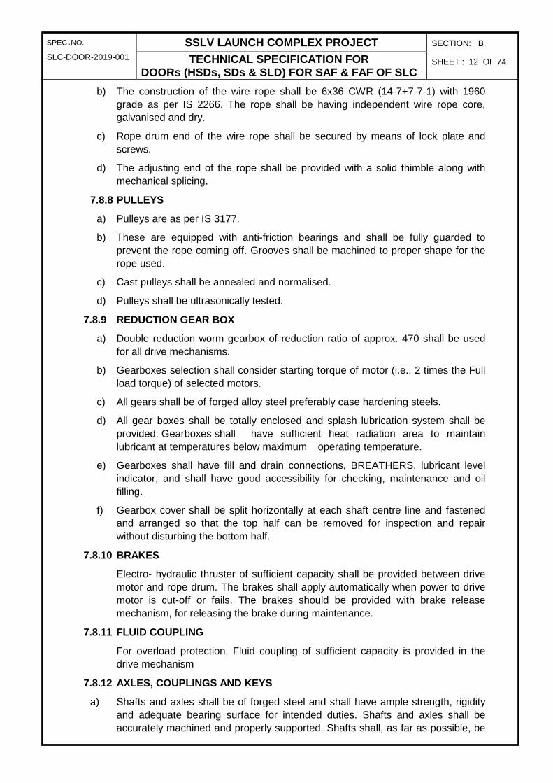
SPEC.NO. SSLV LAUNCH COMPLEX PROJECT SECTION: B
SLC-DOOR-2019-001 TECHNICAL SPECIFICATION FOR DOORs (HSDs, SDs & SLD) FOR SAF & FAF OF SLC
SHEET : 12 OF 74
b) The construction of the wire rope shall be 6x36 CWR (14-7+7-7-1) with 1960 grade as per IS 2266. The rope shall be having independent wire rope core, galvanised and dry.
c) Rope drum end of the wire rope shall be secured by means of lock plate and screws.
d) The adjusting end of the rope shall be provided with a solid thimble along with mechanical splicing.
7.8.8 PULLEYS
a) Pulleys are as per IS 3177.
b) These are equipped with anti-friction bearings and shall be fully guarded to prevent the rope coming off. Grooves shall be machined to proper shape for the rope used.
c) Cast pulleys shall be annealed and normalised.
d) Pulleys shall be ultrasonically tested.
7.8.9 REDUCTION GEAR BOX
a) Double reduction worm gearbox of reduction ratio of approx. 470 shall be used for all drive mechanisms.
b) Gearboxes selection shall consider starting torque of motor (i.e., 2 times the Full load torque) of selected motors.
c) All gears shall be of forged alloy steel preferably case hardening steels.
d) All gear boxes shall be totally enclosed and splash lubrication system shall be provided. Gearboxes shall have sufficient heat radiation area to maintain lubricant at temperatures below maximum operating temperature.
e) Gearboxes shall have fill and drain connections, BREATHERS, lubricant level indicator, and shall have good accessibility for checking, maintenance and oil filling.
f) Gearbox cover shall be split horizontally at each shaft centre line and fastened and arranged so that the top half can be removed for inspection and repair without disturbing the bottom half.
7.8.10 BRAKES
Electro- hydraulic thruster of sufficient capacity shall be provided between drive motor and rope drum. The brakes shall apply automatically when power to drive motor is cut-off or fails. The brakes should be provided with brake release mechanism, for releasing the brake during maintenance.
7.8.11 FLUID COUPLING
For overload protection, Fluid coupling of sufficient capacity is provided in the drive mechanism
7.8.12 AXLES, COUPLINGS AND KEYS
a) Shafts and axles shall be of forged steel and shall have ample strength, rigidity and adequate bearing surface for intended duties. Shafts and axles shall be accurately machined and properly supported. Shafts shall, as far as possible, be

SPEC.NO. SSLV LAUNCH COMPLEX PROJECT SECTION: B
SLC-DOOR-2019-001 TECHNICAL SPECIFICATION FOR DOORs (HSDs, SDs & SLD) FOR SAF & FAF OF SLC
SHEET : 13 OF 74
furnished straight. If shouldered, these shall be provided with fillets of ample radius or shall be tapered to avoid loss of strength and stress concentration. These shall be designed considering allowances for keys.
b) All couplings shall be of steel.
c) Keys and keyways shall conform to IS 2048 / 2291 / 2292 / 2293 as applicable.
7.8.13 DRIVE BASE
a) All drive mechanism elements are mounted on the fabricated drive base.
b) Made of mild steel confirming to Fe410WB; IS: 2062.
c) Fabricated drive base shall be thermally stress relieved before machining.
d) Foundation bolts and foundation for fixing the drive base on the floor is in the scope of tenderer. For grouting the foundation bolts and base frame Conbextra Gp-2 cement shall be used.
7.9 MECHANICAL / END STOP
a) Two nos. of mechanical stops shall be provided on Vertical wheel (Top) track in order to limit the total movement of each HSD leaf. Out of these two mechanical stops, each stop shall be located on each side of the HSD leaf.
b) End stop Shall be made of mild steel confirming to Fe410WB; IS: 2062
Fig.9: Schematic Sketch of Mechanical/ End Stop
7.10 GUARDS
All exposed couplings, shafts, gear wheels, pinions, drives etc. shall be safely encased and guarded.
8.0 TECHNICAL SPECIFICATION OF SWING DOOR (SD)
There swing doors are provided on the SAF & FAF from EL 9.0m of FAF & SAF to get opening as mentioned in following Table.
Location Clear opening at center (m)
Bottom level (m)
Top level (m)
On FAF 5.0 9.0 36.0
On SAF 5.0 9.0 36.0
On SAF LP side
5.0 9.0 45.0

SPEC.NO. SSLV LAUNCH COMPLEX PROJECT SECTION: B
SLC-DOOR-2019-001 TECHNICAL SPECIFICATION FOR DOORs (HSDs, SDs & SLD) FOR SAF & FAF OF SLC
SHEET : 14 OF 74
Fig.10: Schematic 3D view of Swing Door (SD) sub systems
Swing Door (SD) is composed of the following major subassemblies / components:
a) Door Frame
b) Drive Hinge & Idle Hinge
c) Door Hinge Brackets
d) Cyclone locks
e) Swing Drive mechanism comprising Hydraulic actuator, hydraulic power pack, flexible hoses, piping, etc.
f) Insulation
g) Sealing arrangement
Swing Doors (SDs) are configured such that Doors shall swing through 90 degrees with respect to hinge shaft, inside the building by help of hydraulic actuator. Actuator is assembled with door hinge shaft.
SD shall be a complete unit with Door leaf structure, door hinge and Hydraulic actuator unit, cyclone locks, electric hydraulic power pack, flexible hoses all electrical etc. to make the equipment complete in all respects. The steel used for the SD construction shall be of standard quality. All materials used shall be of recent manufacture, free from defects, mill scales, laminations, pittings, flakes, rust etc. All welds shall be free from defects like blowholes, lack of penetration, slag intrusions etc.
A brief description of the constructional features required for each of the above subassemblies / components is listed here below:
8.1 DOOR FRAME
8.1.1 Each SD set comprises RH and LH door frame
8.1.2 The door frame is made of welded steel / rolled structure with built up ‘C’ and ‘I’ sections

SPEC.NO. SSLV LAUNCH COMPLEX PROJECT SECTION: B
SLC-DOOR-2019-001 TECHNICAL SPECIFICATION FOR DOORs (HSDs, SDs & SLD) FOR SAF & FAF OF SLC
SHEET : 15 OF 74
8.1.3 The door frame shall be made of welded steel / rolled structure with built up / standard ‘C’ and ‘I’ sections
8.1.4 Each leaf comprises 4 nos. of ‘C’ sections forming overall size of the door leaf and 7 nos. of ‘I’ sections (5 nos. in horizontal plane and 2 nos. vertical plane). ‘I’ sections are interconnected using rolled sections with necessary stiffening.
SWING DOOR
Width (From C.L. of door opening) (in
mm)
Height
(in mm)
Clear opening
(in mm)
Opening elevation (in m)
Drive level elevation
(in m)
SD-1 2000 9000 5000 9.0 - 18.0 16.0
SD-2 2000 9000 5000 18.0 - 27.0 24.0
SD-3 2000 9000 5000 27.0 - 36.0 32.0
SD-4 2000 9000 5000 36.0 - 45.0 44.0
8.1.5 Each door leaf overlaps the adjacent door leaf from three sides (Top, Centre and Bottom) by means of steel labyrinth sealing plates.
8.1.6 There shall be two steel labyrinth plates enveloping the three sides of each door frame. The spacing and placement of these labyrinth plates shall be such that there will not be any interference with the mating door to help in preventing ingress of water.
8.1.7 The gap in the two labyrinth plates shall be such that there is enough space for door deflection. The face of the labyrinth in the vertical plane shall be fixed with synthetic rubber pads.
8.1.8 To facilitate the aspects of fabrication, transportation, handling and erection of doors at site, the door leaf may be made up of modules with approval from department.
8.2 DRIVE HINGE & IDLE HINGE ARRANGEMENT
FIG.11: SCHEMATIC DRAWING OF DRIVE HINGE ARRANGEMENT OF SD

SPEC.NO. SSLV LAUNCH COMPLEX PROJECT SECTION: B
SLC-DOOR-2019-001 TECHNICAL SPECIFICATION FOR DOORs (HSDs, SDs & SLD) FOR SAF & FAF OF SLC
SHEET : 16 OF 74
8.2.1 There are two drive hinge brackets at top location and two idle hinge brackets at bottom location for each Swing Door to support the self-weight of the door. These brackets are mounted on embedment plates provided on the FAF wall.
8.2.2 Drive hinge arrangement comprises two Drive hinge brackets, one Drive Shaft, two Hinge Bracket, two Taper roller bearing (‘O’ arrangement), bearing retainer, spacer, Shaft locking plate and lock nut- lock washer.
8.2.3 Idle hinge arrangement comprises two idle hinge brackets, one Idle Shaft, two Hinge Bracket, two Taper roller bearing (‘O’ arrangement), bearing retainer, spacer, Shaft locking plate and lock nut- lock washer.
8.2.4 Hydraulic actuator is assembled with drive shaft to swing the door through 90 o. Door will be open inward direction of the building.
8.2.5 Brackets shall be made of mild steel confirming to Mild steel E250-BR; IS: 2062.
8.2.6 These brackets shall be stress relieved before machining. Weld quality shall be radio-graphically checked
8.3 DOOR HINGE BRACKETS
8.3.1 Two fabricated Door hinge brackets are mounted on each swing door leaf. Top bracket is keyed with drive shaft and bottom bracket keyed with idle shaft
8.3.2 Bracket shall be made of mild steel confirming to Mild steel E250-BR; IS: 2062.
8.3.3 These brackets shall be stress relieved before machining.
8.3.4 Weld quality shall be radio-graphically checked
Fig.12: Schematic 3D view of Swing Door Hinge Bracket
8.4 CYCLONE LOCKS
8.4.1 In order to take care of cyclonic wind load all doors are provided with Cyclone locks.
8.4.2 The Cyclone lock mechanism consists of a guided threaded rod and a nut block. A plate shall be provided on the door leaf at each location of the treaded rod.
8.4.3 Whenever Cyclone lock is to be used, threaded rod is manually tightened against the door and the door shall be jammed against the lateral guide wheel channel.
8.4.4 Cyclone locks shall be positioned so as to easy access during operation.
8.4.5 Cap & Screw head of cyclone lock is to be hardened to 40-45 HRC to a depth of 3 to 5mm.

SPEC.NO. SSLV LAUNCH COMPLEX PROJECT SECTION: B
SLC-DOOR-2019-001 TECHNICAL SPECIFICATION FOR DOORs (HSDs, SDs & SLD) FOR SAF & FAF OF SLC
SHEET : 17 OF 74
Fig.13: Schematic Sketch of Cyclone Lock Assembly for SD
8.5 END SEALING
8.5.1 The gap between the door leaf inner face and the outer face of the facility is sealed by providing two rubber pad lining with minimum gap. One part of the rubber pad is fixed on the extended portion of a fabricated bracket welded to the door leaf while pouter face.
8.6 SWING DRIVE MECHANISM
8.6.1 Swinging operation is carried out by the hydraulically operated actuator that is mounted on the top of drive hinge shaft of drive hinge bracket. The hydraulic power pack is also positioned on portal area of the building. The actuator has bore with keyway and rotates the male drive hinge shaft which is keyed with door hinge bracket of swing door. The drive shaft is housed in bearing housings with anti-friction bearings. Bearing housings are part of drive hinge brackets and drive hinge shaft is free to rotate inside it. Drive hinge brackets are mounted on the facility steel structure and Hydraulic actuator is bolted to the top drive hinge bracket.
8.6.2 Swing door is open inward direction of the building.
8.6.3 The detailed specification of Hydraulic power pack and actuator is given separately.
Fig.14: SD Swing Drive Mechanism

SPEC.NO. SSLV LAUNCH COMPLEX PROJECT SECTION: B
SLC-DOOR-2019-001 TECHNICAL SPECIFICATION FOR DOORs (HSDs, SDs & SLD) FOR SAF & FAF OF SLC
SHEET : 18 OF 74
8.6.4 SHAFTS AND KEYS
a) Shafts shall be of forged steel and shall have ample strength, rigidity and adequate bearing surface for intended duties. Shafts shall be accurately machined and properly supported. Shafts shall, as far as possible, be furnished straight. If shouldered, these shall be provided with fillets of ample radius or shall be tapered to avoid loss of strength and stress concentration. These shall be designed considering allowances for keys.
b) Keys and keyways shall conform to IS 2048 / 2291 / 2292 / 2293 as applicable.
8.6.5 POWER PACK BASE FRAME
a) All power pack elements are mounted on the fabricated drive base.
b) Made of mild steel confirming to Fe410WB; IS: 2062.
c) Power packs shall be mounted on steel supports derived from the facility steel structure.
8.7 DOOR CLADDING
Each door leaf is fully cladded with Galvalume sheets for withstanding cyclonic winds as per IS: 875.
8.8 INSULATION
Phenolic resin based foam insulation in board form of thickness 40mm with density of 35±2 kg/cum and thermal conductivity of 0.020 kcal/hm°C wrapped with aluminium sheet (200 micron thick) shall be fixed inside the door leaves to maintain inside temperature at 30°C
8.9 MECHANICAL / END STOP
b) Two nos. of mechanical stops shall be provided on building portal frame at suitable location in order to limit the total swing movement of each SD leaf.
c) Shall be made of mild steel confirming to Fe410WB; IS: 2062
9.0 TECHNICAL SPECIFICATION FOR HYDRULIC SYSTEM FOR ACTUATOR
The specification shall cover the design, engineering, manufacture, procurement, cleaning, assembly, shop testing, painting, packing, supply, site erection, testing & commissioning of twenty (20) nos. of Rotary actuators complete with Hydraulic system for swinging Door (SD).
9.1 QUANTITY:
A. Rotary actuator with hydraulic system - Twenty (20 nos)
One (1) Set of complete package of rotary actuators and hydraulic system shall include the following
• Rack & pinion type Rotary Actuators : One (1) Nos.
• Hydraulic Power Pack Unit & Valve Stand : One (1) set.
• Interconnecting tubing, tube fittings, clamps, : One (1) set
hose assemblies, etc for piping between
hydraulic unit and Rotary Actuators.
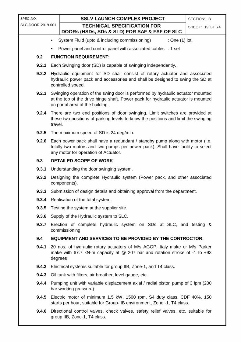
SPEC.NO. SSLV LAUNCH COMPLEX PROJECT SECTION: B
SLC-DOOR-2019-001 TECHNICAL SPECIFICATION FOR DOORs (HSDs, SDs & SLD) FOR SAF & FAF OF SLC
SHEET : 19 OF 74
• System Fluid (upto & including commissioning) : One (1) lot.
• Power panel and control panel with associated cables : 1 set
9.2 FUNCTION REQUIREMENT:
9.2.1 Each Swinging door (SD) is capable of swinging independently.
9.2.2 Hydraulic equipment for SD shall consist of rotary actuator and associated hydraulic power pack and accessories and shall be designed to swing the SD at controlled speed.
9.2.3 Swinging operation of the swing door is performed by hydraulic actuator mounted at the top of the drive hinge shaft. Power pack for hydraulic actuator is mounted on portal area of the building.
9.2.4 There are two end positions of door swinging. Limit switches are provided at these two positions of parking levels to know the positions and limit the swinging travel.
9.2.5 The maximum speed of SD is 24 deg/min.
9.2.6 Each power pack shall have a redundant / standby pump along with motor (i.e. totally two motors and two pumps per power pack). Shall have facility to select any motor for operation of Actuator.
9.3 DETAILED SCOPE OF WORK
9.3.1 Understanding the door swinging system.
9.3.2 Designing the complete Hydraulic system (Power pack, and other associated components).
9.3.3 Submission of design details and obtaining approval from the department.
9.3.4 Realisation of the total system.
9.3.5 Testing the system at the supplier site.
9.3.6 Supply of the Hydraulic system to SLC.
9.3.7 Erection of complete hydraulic system on SDs at SLC, and testing & commissioning.
9.4 EQUIPMENT AND SERVICES TO BE PROVIDED BY THE CO NTROCTOR:
9.4.1 20 nos. of hydraulic rotary actuators of M/s AGOP, Italy make or M/s Parker make with 67.7 kN-m capacity at @ 207 bar and rotation stroke of -1 to +93 degrees
9.4.2 Electrical systems suitable for group IIB, Zone-1, and T4 class.
9.4.3 Oil tank with filters, air breather, level gauge, etc.
9.4.4 Pumping unit with variable displacement axial / radial piston pump of 3 lpm (200 bar working pressure)
9.4.5 Electric motor of minimum 1.5 kW, 1500 rpm, S4 duty class, CDF 40%, 150 starts per hour, suitable for Group-IIB environment, Zone -1, T4 class.
9.4.6 Directional control valves, check valves, safety relief valves, etc. suitable for group IIB, Zone-1, T4 class.

SPEC.NO. SSLV LAUNCH COMPLEX PROJECT SECTION: B
SLC-DOOR-2019-001 TECHNICAL SPECIFICATION FOR DOORs (HSDs, SDs & SLD) FOR SAF & FAF OF SLC
SHEET : 20 OF 74
9.4.7 Pressure gauges, pipelines, pilot operated check valves, etc.
9.4.8 Operators panel or control panel on the Portal area of the building (located adjacent to the power pack) suitable for group IIB, Zone-1, T4 class.
9.4.9 Entire length of piping required from power pack to the actuators mounted at around 5m away.
9.4.10 Flexible hoses required to connect the actuators with the pipelines.
9.4.11 Electrical power / control cables required for erection of the hydraulic actuator system.
9.4.12 Inspection & testing at Supplier’s shop, packing & forwarding, transportation to SLC.
9.4.13 Supervision during assembly of Actuators at SD structure manufacturer’s Shop.
9.4.14 Erection, testing and commissioning of Hydraulic actuator system at SLC.
9.4.15 Painting of all equipment as per the detailed specifications.
9.5 GENERAL TECHNICVAL DATA:
9.5.1 The Hydraulic unit shall be designed and rated to the instructions & recommendations of DIN, CETOP & ISO. The safety instructions shall be considered according to TUV.
9.5.2 The units shall be completely piped and terminated with companion flanges fittings including oil trays as required.
9.5.3 The companion flange / fittings on the manifold blocks are the takeover points for the interconnecting piping.
9.5.4 Provision shall be made for pressure check connections. All such connections shall be equipped with minimess couplings.
9.5.5 Power pack shall be grouted on the building floor at portal area.
9.5.6 Max. Weight of Each door to be rotated : 7.5t.
9.5.7 Max. acceleration / deceleration : 0.003 radian / Sec2
9.5.8 Speed of rotation : 24˚/min.
9.5.9 Angle to be rotated : 90°
9.5.10 Hydraulic Fluid : Fire retardant type Quintolubric N 888-68 of Quaker Chemical
9.5.11 Operating Pressure : Less than 165 bar
9.5.12 Solenoid Valves : JIC, Oil immersed Coils, manual over-ride
9.5.13 Electric Connection : All electrical appliances to be wired up to a common Junction box.
9.5.14 Sealing material : Compatible with the hydraulic fluid
9.5.15 Flexible hoses : High pressure series thermoplastic.
9.5.16 Piping : Seam less stainless steel tubes of material 1.4571 to DIN 17458(1985) with outer diameter to tolerance class T4, as per DIN 2462, Part 1-1981

SPEC.NO. SSLV LAUNCH COMPLEX PROJECT SECTION: B
SLC-DOOR-2019-001 TECHNICAL SPECIFICATION FOR DOORs (HSDs, SDs & SLD) FOR SAF & FAF OF SLC
SHEET : 21 OF 74
9.5.17 Tube Fittings : EO-2 Ermeto Parker Fluid connector or Equivalent
9.5.18 Shut –off/Isolation valves : Ball valves with SS internals/SS needle Valve
9.5.19 Flanges : SAE 4 bolt socket weld type 3000# rating with O rings for low/medium pressure lines SAE 4 bolt socket weld type.
9.5.20 Labelling : All electrical appliances shall be marked with black figures on metal/plastic plates
9.6 DESIGN INPUT
Design input for sizing & selection of rotary actuators and Hydraulic system parameters are given below for guidance only
9.6.1 ROTARY ACTUATORS
• Make : M/s AGOP, Italy / M/s Parker make only.
• Type : Rack & pinion type.
• Model / Capacity : 67.7 kN-m
• Maximum operating pressure : 207 bar
• Operating pressure : 165 bar
• Load Torque : 60 kN-m
• Rotation : 90°
• Rotation tolerance : 90° (-0° +2°)
• Rotation stroke : -1° to +93°
• Maximum Breakaway pressure : 5 Bar
• Mounting Orientation : Vertical Axis of the Stub shaft
• Seal Material : Viton PTFE-Bronze
• Proof Pressure : 420 Bar
• Operating temperature : 0° to 100°C
• Volume capacity : 9.2 litres.
• The actuators shall be supplied with keyway positions.
• Actuators shall be assembled with respective fixed vertical shafts of bogies under these keyway positions and then are keyed. These positions shall be considered as initial or starting or 0° position.
• Actuator shall have clear marks indicating 0˚ and 90˚ position for easy identification.
• The actuator model having load capacity of 67.7 kN-m has been selected based on the load conditions & torque requirement.
• Taking the input data of the selected actuator, the broad specification of hydraulic system to be arrived.

SPEC.NO. SSLV LAUNCH COMPLEX PROJECT SECTION: B
SLC-DOOR-2019-001 TECHNICAL SPECIFICATION FOR DOORs (HSDs, SDs & SLD) FOR SAF & FAF OF SLC
SHEET : 22 OF 74
9.6.2 DESCRIPTION OF HYDRAULIC EQUIPMENT
• The tank and entire piping & fittings shall be of stainless steel construction.
• The hydraulic power unit consisting of tank, pump-motor unit, return line filter, pump relief valve, direction control valves, manually operated stand-by pumping unit, etc shall be assembled and located inside an all-weather steel cabinet.
• Complete system shall be operated at 200 bar pressure.
• All Pressure relief valves shall a provision for manually varying pressure relief valve setting from 10 to 207 bar.
• Major units of the hydraulic system shall be as given below.
• Tank unit with mounted accessories.
• Pumping Unit (motor operated) along standby / redundant pumping unit.
• Valve stand.
• Actuator
• Interconnecting piping.
• Flexible Hoses.
9.6.3 TANK AND ACCESSORIES.
TANK:
• Fluid tank shall be of Stainless steel 316L welded construction
• Capacity of the tank is to be calculated based on the fluid consumption by of rotary actuators, plumbing / hoses and necessary reserve storage in the tank.
TANK ACCESSORIES:
• Oil level indicator : for visual indication of oil level.
• Filler/breather : To compensate level differences, to refill fluid with 5 µm filter
• Return line filter clog indicator : To indicate the filter clog status
• Drain valve : to drain the tank
• Return line filter : to filter the fluid coming back to tank
• Float switch (3 contacts) : to signal the oil level in the tank
9.6.4 PUMPING UNIT
• Pump : To supply pressurised fluid.
• Minimum flow rate : 3 lpm at 110 bar
• Electric motor, 3Ø, 415V, 50Hz : To drive the pump
• Pressure Relief Valve, 0-400 bar : Pump Safety protection against over pressure
• Pressure gauge, 0-400 bar : To read discharge pressure.

SPEC.NO. SSLV LAUNCH COMPLEX PROJECT SECTION: B
SLC-DOOR-2019-001 TECHNICAL SPECIFICATION FOR DOORs (HSDs, SDs & SLD) FOR SAF & FAF OF SLC
SHEET : 23 OF 74
• Gauge adapter minimess hose & : To connect Pr.Gauge to the
minimess connecter minimess coupling
• Unloading Valve : To Unload pump when actuator is not being operated
• Hand Pump : To function as stand-by pumping unit
• Check Valve : To avoid back flow in pump discharge line
• Minimess connecter : To facilitate connection to the Pressure Gauge.
9.6.5 VALVE STAND (ALL ITEMS TO BE MOUNTED ON MANIF OLD BLOCKS)
• Direction Control valve : To change the actuator rotation direction.
• Flow control module : To regulate speed of actuators (Double throttle check valve)
• Minimess connecter : To read pressure in delivery line
9.6.6 HOSE ASSEMBLY
• Hose assembly : To provide flexibility for connection between power pack & actuator.
• Piping : To transfer hydraulic oil from power pack to the actuators
9.7 DESIGN CONSIDERATION AND TECHNICAL NOTES
9.7.1 Pump-motor units / Power Unit assembly shall be mounted on anti-vibration pads
9.7.2 Tungsten Inert Gas (TIG) welding shall be done at all butt weld pipe joints, if any.
9.7.3 Material of manifold block shall be GGG-40 to DIN 1693 Part 1-1993. Test certificates to be submitted in this respect.
9.7.4 Direction control valves shall be selected for maximum 5 bar Pressure drop for blind end flow.
9.7.5 Speed control valves shall be selected for maximum 5 bar (maximum open condition) pressure drop.
9.7.6 Shut off valves and check valves shall be of same size as that of pipelines.
9.7.7 Total pressure drop in any circuit including manifold block of valve stand, for the flow indicated for the circuit, should not exceed 15 bar.
9.7.8 All solenoids to be provided with indicating lamps and plug in type connectors (DIN connector). All solenoid coils to be oil immersed type, rated for continuous duty and epoxy coated.
9.7.9 After fabrication, all the pipes to be cleaned, degreased, pickled, neutralized, rinsed and lubricated.
9.7.10 All pipelines to be clamped with Tube clamps (polypropylene heavy series stauff clamps / eqvt).
9.7.11 All electrical items such as direction control valves, level switches, etc to be completely wired up to a junction box. Spare terminals shall be provided.
9.7.12 All systems and piping shall be pressure tested at 1.5 times working pressure. Performance test and pressure drop test shall be carried out during inspection.

SPEC.NO. SSLV LAUNCH COMPLEX PROJECT SECTION: B
SLC-DOOR-2019-001 TECHNICAL SPECIFICATION FOR DOORs (HSDs, SDs & SLD) FOR SAF & FAF OF SLC
SHEET : 24 OF 74
9.7.13 After testing, the unit (excluding tank) shall be filled with the system fluid and all open terminations shall be closed for air tightness.
9.7.14 All equipment shall be packed in seaworthy packing with all necessary measures to protect equipment against corrosion and damage during handling at the port, transit or during storage in open space.
9.8 ELECTRICAL CONTROLS
9.8.1 At swinging in / Swing out end position limit switches shall be provided for indicating completion of swinging in or swinging out position.
9.8.2 Local control panel for Hydraulic power pack shall be provided with following control features
A. Power On / Off
B. Pump On / Off
C. Manual selection for Pump 1 or Pump 2.
D. Push button for Swinging in operation
E. Push button for Swing out operation
F. Indication lamp during Swinging in operation
G. Indication lamp for swing out operation
H. Indication lamp for Pump 1 On
I. Indication lamp for Pump 2 On
J. Display of actuation of Swinging in limit switch
K. Display of actuation of Swing out limit switch.
9.9 ELECTRICAL SPECIFICATION:
9.9.1 All electrical equipment / items shall be flame proof of group IIB environment as per IS: 2148-1981, for hazardous area zone I as per IS: 5572-1994 and temperature classification T4 as per IS:8239-1976, IP-55 enclosure
9.9.2 Available power supply is 415V±10%, 3 ph, 4 wire, frequency 50Hz ±5% and auxiliary supply is 240V, 50Hz, AC.
9.9.3 All the electrical equipment should confirm to latest standard BIS codes and the practices followed for design, installation, commissioning, operation and maintenance.
9.10 INSPECTION AND TESTING OF HYDRAULIC EQUIPMENT AT CONTROCTOR’S SITE AND PURCHASER SITE.
9.10.1 All functional checks of Hydraulic rotary actuators system are to be carried out in the presence of the ISRO representative at sub-vendor site.
9.10.2 Documented procedures shall be available for all tests, control of testing equipment, control of test results and data.
9.10.3 Stage wise and/ or final Inspection will be carried out by ISRO as per the approved Quality Assurance Plan (QAP). In case, any equipment is found to mal-function or give sub-standard performance during this activity, the same shall be replaced immediately.

SPEC.NO. SSLV LAUNCH COMPLEX PROJECT SECTION: B
SLC-DOOR-2019-001 TECHNICAL SPECIFICATION FOR DOORs (HSDs, SDs & SLD) FOR SAF & FAF OF SLC
SHEET : 25 OF 74
9.10.4 All systems and piping shall be pressure tested at 1.5 times system working pressure. Performance test and pressure drop test shall be carried out during inspection.
9.10.5 Hydraulic actuator shall be proof pressure tested. However, relevant test certificates shall also be obtained from the supplier / manufacturer.
9.11 GENERAL ERECTION PROCEDURE:
9.11.1 Equipment delivered at site to be inspected and checked as per Packing List. All sub-systems shall be placed at respective positions.
9.11.2 The sub-systems shall be levelled and aligned. Packing plates/ shims have to be used as required.
9.11.3 Fabricate the piping segments wherever required to complete the piping layout and clean the piping segments by approved cleaning procedure of pickling, passivating, rinsing, drying & oiling.
9.11.4 Tighten fixing bolts evenly.
9.11.5 Recheck levels of equipment.
9.12 GENERAL INSTRUCTIONS FOR ERECTION OF INTERCONNECTING PIPING
9.12.1 Pipe routes shall be checked with respect to the pipe system layout and pipe line drawings.
9.12.2 All supports shall be checked for horizontality and verticality before fixing.
9.12.3 Ensure that pipe lines do not interfere with other pipes / equipment / installations.
9.12.4 Supports shall be properly bolted / welded to prevent deformation / slip-off after installation of piping.
9.13 PIPE LINE INSTALLATION
9.13.1 Pipelines shall be connected to mechanical equipment after final alignment and levelling so that the connections are free from stresses.
9.13.2 Piping close to equipment shall be installed in such a way that dismantling and inspection of the equipment will not be hindered.
9.13.3 Edge preparation of pipes for welding shall be to ANSI B 16.25-1992 and shall be ground smooth.
9.13.4 The welding surfaces shall be uniform, smooth and free from surface defects, rust scale, grease, paint, etc. Welding shall be free from slag.
9.13.5 After ground fabrication, pipelines shall be placed in position on temporary supports and ‘in situ’ welding shall be carried out, if necessary.
9.13.6 Hydraulic pressure testing of piping for hydraulic lines shall be carried out at 1.5 times system working pressure.
9.14 PIPE LINE CLAMPIMG
9.14.1 All the pipes shall be clamped and supported.
9.14.2 All pipes shall be clamped with Polypropylene Pipe Clamps (PP clamps).

SPEC.NO. SSLV LAUNCH COMPLEX PROJECT SECTION: B
SLC-DOOR-2019-001 TECHNICAL SPECIFICATION FOR DOORs (HSDs, SDs & SLD) FOR SAF & FAF OF SLC
SHEET : 26 OF 74
9.14.3 Generally, pipes shall be clamped at every 1.5 meters in straight run. At bends, clamps shall be provided on either side of bend, on straight length of pipe, as close to the bend as possible.
9.14.4 The support can be provided from top/bottom of pipe as per site condition.
9.14.5 The clamp can be directly welded to the platform structure or to the angle / channel welded to the structural body depending upon site condition.
9.14.6 Before welding the base plate of PP Clamp to the structure/angle/channel, the PP clamp is to be dismantled and bottom half to be separated from steel part to avoid burning of the polypropylene part.
9.14.7 After welding of base plate is completed and the plate cools down, the bottom half of PP clamp has to be assembled with base plate. On the bottom half of PP clamp, pipe is to be placed. On top of pipe, the top half of PP clamp is to be placed. Then top plate is placed in position, the bolts are inserted and tightened. This completes the clamping procedure.
9.15 INSPECTION TESTING AND COMMISSIONING AT SITE:
9.15.1 Checking the operation of all actuators in clock wise and anti-clockwise directions minimum five times.
9.15.2 Checking the working of all limit switches for all actuators.
9.15.3 Stage wise and/ or final Inspection shall be carried out on the basis of approved circuit drawings and QAP. Pressure test certificates, internal inspection report, material test certificates and manufacturer’s test certificates shall be enclosed with the inspection call.
9.15.4 In case, any equipment is found to mal-function or give sub-standard performance during this activity, it shall be replaced free of cost.
10.0 TECHNICAL SPECIFICATION OF SLIDING DOOR
One Sliding door (SLD) is provided on rear side of FAF from EL 0.0m to EL 9.0m to get opening of 12 m wide and 9 m height from 0 m elevation.
Fig.45: Schematic 2D view of SLD leaf
Sliding Door (SLD) is composed of following major subassemblies / components:
(i) Door Frame

SPEC.NO. SSLV LAUNCH COMPLEX PROJECT SECTION: B
SLC-DOOR-2019-001 TECHNICAL SPECIFICATION FOR DOORs (HSDs, SDs & SLD) FOR SAF & FAF OF SLC
SHEET : 27 OF 74
(j) Drive wheel assembly
(k) Idle wheel assembly
(l) Guide wheel assembly
(m) Cyclone locks
(n) Insulation
(o) Sealing arrangement
Sliding Door (SLD) is configured such that Door shall slide laterally sidewise on wheels and tracks driven by Flame proof geared motor assembled with drive wheel. Door along with the wheel assembly integral with the door frame horizontally slide on the track mounted on the FAF ground floor. SLD shall slide inside the building along the track.
SLD shall be a complete unit with one Door leaf structure, Drive wheel assembly, Idle wheel assembly, Gide wheel assembly, cyclone locks, Flame proof geared motor assembled with drive wheel and all electrical etc. to make the equipment complete in all respects. The steel used for the HSD construction shall be of standard quality. All materials used shall be of recent manufacture, free from defects, mill scales, laminations, pittings, flakes, rust etc. All welds shall be free from defects like blowholes, lack of penetration, slag intrusions etc.
10.1 SLD DOOR FRAME
10.1.1 SLD comprises of a single door leaf frame
10.1.2 Door frame is as mentioned in following table:
10.1.3 Door frame is made of welded steel / rolled structure with built up ‘C’ and ‘I’ sections
10.1.4 Each leaf comprises 4 nos. of ‘C’ sections forming overall size of the door leaf and 7 nos. of ‘I’ sections (5 nos. in horizontal plane and 2 nos. vertical plane). ‘I’ sections are interconnected using rolled sections with necessary stiffening.
Width (From C.L. of door opening)
(in mm)
Height (in mm)
Clear opening (in mm)
Opening elevation (in m)
Drive level elevation (in m)
12000 8150 12000 0.0-8.0 Assembled with drive wheel
10.1.5 Door leaf overlaps the adjacent building from two sides (Top and Bottom) by means of steel labyrinth sealing plates.
10.1.6 There shall be two steel labyrinth plates enveloping the two sides of each door frame. The spacing and placement of these labyrinth plates shall be such that preventing ingress of water.
10.1.7 The gap in the two labyrinth plates shall be such that there is enough space for door deflection.
10.1.8 The face of the labyrinth in the vertical plane shall be fixed with synthetic rubber pads.

SPEC.NO. SSLV LAUNCH COMPLEX PROJECT SECTION: B
SLC-DOOR-2019-001 TECHNICAL SPECIFICATION FOR DOORs (HSDs, SDs & SLD) FOR SAF & FAF OF SLC
SHEET : 28 OF 74
10.1.9 To facilitate the aspects of fabrication, transportation, handling and erection of doors at site, the door leaf may be made up of modules with department clearance
10.2 DRIVE WHEEL & IDLE WHEELASSEMBLY
10.2.1 Drive Wheel assembly for SLD comprises flame proof geared motor assembled with drive wheel shaft.
10.2.2 There are one drive wheel and one idle wheel at bottom to support the self-weight of the door.
10.2.3 One flame proof geared motor is assembled with drive wheel to move the SLD above the track.
10.2.4 The minimum hardness of the wheel rim shall be maintained between 300 and 350 BHN with minimum depth of 10 mm.
10.2.5 The minimum hardness of the wheel track shall be maintained between 40-45 HRc with minimum depth of 10 mm.
10.2.6 Bracket, Bearing retainer, spacer and axle lock plate is made of mild steel confirming to Fe410WB; IS: 2062.
Fig.56: Drive Wheel Assembly of SLD Fig.67: Idle Wheel Assembly of SLD
10.3 GUIDE WHEELS ASSEMBLY
10.3.1 Guide wheel assembly for SLD comprises horizontal wheels moving inside a fabricated guide channel with track which is attached to the FAF wall.
10.3.2 There are three numbers of guide wheels which are mounted on top side of SLD leaf with equally spaced. Guide wheel assembly are designed to withstand the operating wind loads, lateral loads and eccentric loads.
10.3.3 Guide wheel assembly comprises Plain Wheels, Bracket, Axle, Taper roller bearing (‘O’ arrangement), bearing retainer, spacer, axle locking plate and lock nut- lock washer.
10.3.4 Guide wheel assembly with wheel of Ø350 mm x 120 mm shall be provided.
10.3.5 Guide wheels are made of alloy forged steel 40crMo3 and axles shall be made of alloy forged steel 40NiCr4Mo3.

SPEC.NO. SSLV LAUNCH COMPLEX PROJECT SECTION: B
SLC-DOOR-2019-001 TECHNICAL SPECIFICATION FOR DOORs (HSDs, SDs & SLD) FOR SAF & FAF OF SLC
SHEET : 29 OF 74
10.3.6 The minimum hardness of the wheel rim shall be maintained between 300 and 350 BHN with minimum depth of 10 mm.
10.3.7 The minimum hardness of the wheel track / Liners shall be maintained between 40-45 HRc with minimum depth of 10 mm.
10.3.8 Bracket, bearing retainer, spacer and axle lock plate shall be made of mild steel as specified in Tender drawing.
Fig.77: Idle Wheel Assembly of SLD
10.4 CYCLONE LOCKS
10.4.1 In order to take care of cyclonic wind load all doors are provided with Cyclone locks.
10.4.2 Cyclone lock mechanism consists of a guided threaded rod and a nut block. A plate shall be provided on the door leaf at each location of the treaded rod.
10.4.3 Whenever Cyclone lock is to be used, threaded rod is manually tightened against the door and the door shall be jammed against the lateral guide wheel channel.
10.4.4 Cyclone locks shall be positioned so as to easy access during operation.
10.4.5 Cap & Screw head of Cyclone lock is to be hardened to 40-45 HRC to a depth of 3 to 5mm.
10.5 MECHANICAL / END STOP
a) Two nos. of mechanical stops shall be provided on track in order to limit the total movement of SLD leaf. Out of these two mechanical stops, each stop shall be located on each side of the SLD leaf.
b) End stop Shall be made of mild steel confirming to Fe410WB; IS: 2062
10.6 Each door leaf is fully cladded with coated Galvalume sheets for withstanding cyclonic winds as per IS: 875.
10.7 Phenolic resin based foam insulation in board form of thickness 40mm with density of 35±2 kg/cum and thermal conductivity of 0.020 kcal/hm°C wrapped with aluminium sheet (200 micron thick) shall be fixed inside the door leaves to maintain inside temperature at 30°C
10.8 END SEALING
The gap between the door leaf inner face and the outer face of the FAF is sealed by providing two rubber pad lining with minimum gap. One part of the rubber pad is fixed on the extended portion of a fabricated bracket welded to the door leaf while pouter face.

SPEC.NO. SSLV LAUNCH COMPLEX PROJECT SECTION: B
SLC-DOOR-2019-001 TECHNICAL SPECIFICATION FOR DOORs (HSDs, SDs & SLD) FOR SAF & FAF OF SLC
SHEET : 30 OF 74
11.0 TECHNICAL SPECIFICATION FOR ELECTRICAL ITEMS F OR SLD
All Electrical systems shall be rated for 3 phase, 415 V±10%, and 50Hz power supply and in case single phase is used the same shall be as per the above standard.
Incoming source panel to the door system is located at 4 m level.
Cables are to be taken by contractor from the incoming source panel to the Local control panels located near the drive locations for all the doors. Drive locations are mentioned in table after the clause 7.1.2.
11.1 ELECTRIC MOTORS
The drive motor shall be suitable for duty class S4, cycle duration factor 40% and number of cycles per hour shall be not less than 150. The motor rating shall be selected such a way that the motor will draw less than 80% rated current at standard operating conditions.
11.2 LOCAL CONTROL PANELS
a) A local control panel shall be provided by the contractor for the operation of the doors drive mechanism. The contactor rating shall be selected one rating higher than the design requirement. Power cable (200 m) & the interconnecting cables between the local control panel and limit switches shall also be supplied by the Contractor.
b) The LCP shall generally include On/Off push buttons, 3 phase indications, On/Off &trip indications, necessary contactor, overload and necessary protection devices.
c) The requirements for the Control panel shall be as per the specifications.
11.3 LIMITSWITCHES
A) The drive system for doors shall be provided with weather proof of IP: 65 or better track type limit switches for end limit and stop.
B) Supply and testing of limit switches shall be as per details and specifications.
C) All electrical systems, limit switches are to be inspected by PURCHASER before installation
11.4 CABLES
All power and control cables shall be XLPE insulated copper conductor and armoured as per BIS standards and BIS marked & as per the brands approved by the purchaser.
11.5 CABLE LAYING
The power and control cables shall be laid on suitable GI cable trays fixed on the walls for the size and type of the cables used. The minimum tray size shall be 50X50mm including supply and installation.
11.6 EARTHING
a) The structures, motors / brakes frames, metal enclosures of all electrical equipment, conduit and trays shall be effectively grounded with double earthing and shall be connected to building earth.

SPEC.NO. SSLV LAUNCH COMPLEX PROJECT SECTION: B
SLC-DOOR-2019-001 TECHNICAL SPECIFICATION FOR DOORs (HSDs, SDs & SLD) FOR SAF & FAF OF SLC
SHEET : 31 OF 74
b) SLC will only provide ground rise at suitable location for grounding. Further connection from this riser to doors system for earthing shall be in tenderer scope.
12.0 LIST OF DRAWINGS
The list of drawings mentioned below are tentative general arrangement drawings only and for tendering purpose only. Fabrication drawings will be issued after finalisation of order.
Sl no.
Drawing No. Description
Horizontal Sliding Door (HSD)
1 10-04-SLC-02-001/A1, Sheet 1 of 2 General Assembly of HSD (12 x 9m) for SAF & FAF
2 10-04-SLC-02-001/A1, Sheet 2 of 2 HSD Structural Details (12 x 9m)
3 10-04-SLC-02-003/A1, Sheet 1 of 3 Vertical Wheel & Vertical guide wheel Assembly (HSD – 12 x 9m)
4 10-04-SLC-02-003/A1, Sheet 2 of 3 Vertical Wheel & Vertical guide wheel , Part Detail -1 (HSD – 12 x 9m)
5 10-04-SLC-02-003/A1, Sheet 3 of 3 Vertical Wheel & Vertical guide wheel , Part Detail -2 (HSD – 12 x 9m)
6 10-04-SLC-02-004/A1, Sheet 1 of 2 Horizontal Guide wheel Assembly (HSD – 12 x 9m)
10 10-04-SLC-02-004/A1, Sheet 2 of 2 Horizontal Guide wheel Details (HSD – 12 x 9m)
12 10-04-SLC-02-005/A2, Sheet 1 of 2 Cyclone Lock Assembly (HSD – 12 x 9m)
13 10-04-SLC-02-005/A2, Sheet 2 of 2 Cyclone Lock Details (HSD – 12 x 9m)
14 10-04-SLC-02-006/A2, Sheet 1 of 3 Drive System Assembly (HSD – 12 x 9m)
15 10-04-SLC-02-006/A1, Sheet 2 of 3 Drive System Base Structure Details (HSD – 12 x 9m)
16 10-04-SLC-02-006/A2, Sheet 3 of 3 Rope Drum Details (HSD – 12 x 9m)
17 10-04-SLC-02-007/A1, Sheet 1 of 4 Rope Pulley Assembly Layout (HSD – 12 x 9m)
18 10-04-SLC-02-007/A2, Sheet 2 of 4 Rope Pulley Assembly Details (HSD – 12 x 9m)
19 10-04-SLC-02-007/A2, Sheet 3 of 4 Rope Pulley Part Details -1 (HSD – 12 x 9m)
20 10-04-SLC-02-007/A2, Sheet 4 of 4 Rope Pulley Part Details -2 (HSD – 12 x 9m)
Swing Door (SD)
21 10-04-SLC-01-002/A1, Sheet 1 of 2 General Assembly of Swing Door( 2 x9m) for SAF & FAF
22 10-04-SLC-01-002/A1, Sheet 2 of 2 Structural Details (2 x9m)

SPEC.NO. SSLV LAUNCH COMPLEX PROJECT SECTION: B
SLC-DOOR-2019-001 TECHNICAL SPECIFICATION FOR DOORs (HSDs, SDs & SLD) FOR SAF & FAF OF SLC
SHEET : 32 OF 74
23 10-04-SLC-01-004/A1, Sheet 1 of 1 Cyclonic Lock for Swing Door (2 x9m)
Sliding Door (SLD)
24 10-04-SLC-01-001/A1, Sheet 1 of 3 General Assembly of Sliding Door( 12 x9m)
25 10-04-SLC-01-001/A1, Sheet 2 of 3 Sliding Door Structure Details ( 12 x9m)
26 10-04-SLC-01-001/A1, Sheet 3 of 3 Idle, Drive & Guide Wheel Details of Sliding Door ( 12 x9m)
13.0 MANUFACTURING, ASSEMBLY, TESTING AND INSPECTIO N
13.1 The realisation of manufacturing and assembly of doors shall be carried out in the following manner:
13.2 AT MANUFACTURER’S WORKS:
a) All mechanism, such as Drives, Swing Drive system, Pulley system, Vertical Wheel assembly, Lateral guides, Cyclone Locks, Hinge etc. shall be manufactured, assembled and tested at manufacturer’s work in presence of TPI & department representative.
b) If required, doors can be fabricated in modules at manufacturer’s works and transported to site.
13.3 AT SITE:
a) Doors shall be fabricated, erected and tested at site for free movement of the doors.
b) Alignment of vertical pulleys / horizontal pulleys with respect to Horizontal Drive assemblies is to be checked.
c) Alignment of Hydraulic actuator with swing door is to be checked.
13.4 GENERAL INSTRUCTION FOR FABRICATION AND ERECTI ON ARE SPECIFIED IN THE SUBSEQUENT CLAUSES.
13.4.1 The fabrication of components shall confirm to provisions of IS: 800 – 2013
13.4.2 All rolled material before being laid off shall be clean, free from bends, twist etc. and straight within tolerance allowed by IS: 1852 – 1885.
13.4.3 For butt-weld joints, edge preparation shall be preferably done by machining and may be done by mechanically controlled gas cutting machine. Sub surfaces shall be ground cleaned and inspected before fitting/ welding.
13.4.4 Welding shall be performed as per IS: 9595 – 1996.
13.4.5 All welding shall be carried out by qualified and approved welders shall perform welding in accordance to ASME Sec IX.
13.4.6 Unless otherwise specified on drawings, tolerances for fabrication shall be as per ISO: 13920.
13.4.7 Edge preparation shall be carried out for all plates before welding.
13.4.8 Unless otherwise specified on drawings, all butt welds shall be full penetration welds.

SPEC.NO. SSLV LAUNCH COMPLEX PROJECT SECTION: B
SLC-DOOR-2019-001 TECHNICAL SPECIFICATION FOR DOORs (HSDs, SDs & SLD) FOR SAF & FAF OF SLC
SHEET : 33 OF 74
13.4.9 Unless otherwise specified on drawings, all fillet welds shall be 50% of the minimum plate thickness and shall be on both sides of the plate. Also, the weld shall be continuous.
13.4.10 Welding sequence shall be such that the distortion and residual stresses are minimised. All welds shall be deposited in proper sequence so as to balance the applied heat as far as possible. (A wandering sequence shall be used whenever necessary).
13.4.11 The procedure to be followed by contractor for all weld repairs shall be subject to approval by the department.
13.4.12 Threaded joints that are to be seal welded shall be thoroughly cleaned before welding.
13.4.13 Stress relieving shall be carried out for all fabricated components prior to its machining.
13.4.14 All sharp corners of machined/ fabricated items shall be smoothened by de-burring, hand grinding, chipping and filing.
13.4.15 Fabricator employed at site shall have adequate machining, welding, metrology and portable NDT facilities.
13.4.16 All fabrication work undertaken in parts shall bear distinct match marking to facilitate further identification and erection.
13.4.17 During manufacturing, assembly, erection and commissioning bolt tightening shall be carried out using torque wrench/ impact wrench to ensure required tightening/ tension in the bolts.
13.5 FABRICATION AND MANUFACTURERS WORKS
13.5.1 Base frame of the drive mechanism shall be machined to maintain parallelism between its resting face and equipment mounting face.
13.5.2 The components of drive mechanism viz. Motor, coupling, brake, reduction gear box and rope drum shall be assembled at manufacturer works as per assembly instructions.
13.5.3 Drive mechanism base frame as well as structure shall have suitable provision for lifting hooks.
13.5.4 Vertical wheel assembly, Lateral guide wheel assembly, guide pulley arrangement, cyclone locks etc. Shall be manufactured, assembled tested at manufacturers works and shall be brought to site in grease packed condition.
13.6 FABRICATION AT SITE
13.6.1 For fabrication of doors (HSDs & SDs) at site, accurately levelled floor bed shall be constructed at site
13.6.2 Structural members of the door shall be laid on the fabrication bed. The edges of the members shall be aligned for squareness, parallelism and flatness to required accuracy and tack welded. Following this intermediate members and bracing shall be tack welded ensuring required geometrical parameters.
13.6.3 The structure shall be offered for stage inspection following tack welding while full welding shall be done upon inspection clearance

SPEC.NO. SSLV LAUNCH COMPLEX PROJECT SECTION: B
SLC-DOOR-2019-001 TECHNICAL SPECIFICATION FOR DOORs (HSDs, SDs & SLD) FOR SAF & FAF OF SLC
SHEET : 34 OF 74
13.6.4 The reference position for tracking beam (wheel track), wheel assembly, guide pulley, lateral guide wheels assembly, cyclone lock bracing etc. shall be taken after positioning the door on the floor mounted tracking beam for HSD-1 and marking shall be done ensuring proper alignment.
13.6.5 Following this, the door shall be brought to levelled bead and tracking beam (wheel track), wheel assembly, guide pulley, lateral guide wheels assembly, cyclone lock bracing etc. shall be tack welded, inspected and full welded using supports/ fixtures wherever required.
13.6.6 Structural channels of size more than 400mm if used in door construction shall be fabricated by welding appropriate sections/ plates.
13.6.7 The labyrinth seal plates shall be welded in required sequence to ensure perfect sealing.
13.6.8 After fabrication and inspection of door frame (leaf) structure, the outside face of door-frame shall be welded with cover sheet.
13.6.9 After welding of cover sheet on outside face, the door shall be taken for load testing.
13.6.10 The door shall be cleaned, grit blasted and primer painted as both inside/ outside as per painting instructions. All machined surfaces are to be protected with anti-corrosive coats. All box sections to be painted before closing.
13.6.11 The thermal insulation sheets shall be pasted to the inside wall of the door as specified.
13.7 REQUIREMENTS TO BE FULFILLED BY DOORS
13.7.1 Machined parts/ brackets/ plates shall be aligned and welded on to the fabricated door frame.
13.7.2 Misalignment of vertical wheels, lateral guide wheels and wheel tracks and channels shall be limited to ± 2 mm.
13.7.3 Doors shall be placed in position from sides only in view of vertical labyrinth plates. Suitable erection fixtures/ structures shall be considered.
13.7.4 Door cladding plates shall be welded water tight.
13.7.5 Water sealing labyrinth plates on the door shall be welded in place after cladding plates are welded. Perpendicularity of placement of these plates shall be limited to ± 0.5 mm.
13.8 ERECTION SEQUENCE
13.8.1 PRE-REQUISITE FOR ERECTION:
a) Civil works of building shall be complete in all respect and building material including scaffoldings shall be removed and area shall be cleaned.
b) Preparation of surface for crane, etc. prior to mobilising the doors is in the scope of the contractor.

SPEC.NO. SSLV LAUNCH COMPLEX PROJECT SECTION: B
SLC-DOOR-2019-001 TECHNICAL SPECIFICATION FOR DOORs (HSDs, SDs & SLD) FOR SAF & FAF OF SLC
SHEET : 35 OF 74
13.8.2 TRANSPORTATION & TEMPORARY PLACEMENT:
a) The material shall be loaded on truck/ trailer at Stores/ Fabrication yard using mobile crane transported to actual site and unloaded at site using mobile crane.
b) Mobile crane of adequate capacity and boom length shall be used for handling and erecting Doors structure & drive mechanisms.
c) Sufficient nos. of motorised winches at floor level shall be used to lift the door, if required.
d) Along with construction of facility, erection of drive system shall be taken up with clearance from department.
13.8.3 ASSEMBLY & FABRICATION:
Typical activities in assembly sequence are as follows
a) All the doors shall be fabricated at site / manufacturer’s works.
b) The erection shall be taken up in subassemblies as per erection sequence.
13.8.4 SUPPORT STRUCTURE & MATERIAL HANDLING EQUIPM ENT:
a) Temporary means / structure/ gadgets shall be deployed for lifting of equipment to various heights up to 47 meter.
b) Temporary means for lifting such as motorised rope drum arrangements mounted on temporary foundations at the given elevation shall be arranged.
c) Mobile cranes with adequate capacity and boom length shall be used to erect Doors.
d) Suitable scaffolding, ladders, supports etc. shall be used to facilitate erection work.
13.8.5 ERECTION PROCEDURE:
Typical Erection Sequence shall be as follows:
a) Install and align drive system of Doors.
b) Erect, align and grout the bottom rail.
c) Bracket for lateral guide wheels of HSD shall be assembled with the door.
d) Hinge Brackets of SD shall be assembled with the door.
e) Install and align bracket for cyclone locking system.
f) Install and align all pulleys.
g) Lift door using mobile crane and place on the bottom rail.
h) Lift SDs using mobile crane and assembles with embedment plate provided on the facility wall.
i) Secure the door in position
j) Align the lateral guide wheels, cyclonic locking system and pulley systems.
k) Lay ropes and fasten in position.
l) Install electrical system.

SPEC.NO. SSLV LAUNCH COMPLEX PROJECT SECTION: B
SLC-DOOR-2019-001 TECHNICAL SPECIFICATION FOR DOORs (HSDs, SDs & SLD) FOR SAF & FAF OF SLC
SHEET : 36 OF 74
m) Clean and first fill all the drives.
n) Check for free movement mechanically.
o) Repeat the operations for other doors.
14.0 COMMISSIONING
14.1 Inspection and testing during/after erection shall be as per QAP.
14.2 Supplier shall submit detailed erection plan and procedure along with erection loads on building & also on parts being lifted shall be submitted for approval.
14.3 Supplier shall depute adequate qualified personnel i.e., Engineers/supervisor/ foreman, (for mechanical and electrical), fitters, riggers, and electricians and helpers for carrying out quality erection work at our site within schedule.
14.4 Material (lifting equipment, lifting tackles, etc) required during erection are in Bidder’s scope. All lifting machines / tackles used shall be tested & certified as per standards before their usage for lifting crane.
14.5 Third Party Inspection Agency also shall be involved for final clearance & usage.
15.0 PRELIMINARY SPECIFICATIONS OF MAJOR BOUGHT OUT ITEMS
All bought items are to be inspected by department representative & TPIA at the sub-vendors site before despatching to Vendors site.
BOUGHT OUT ITEMS FOR HSD DRIVE
S.No. Components Specifications
1 Wire rope for door drive arrangement
Usha Martin make, Powerform 8 with Tensile grade 2160 N/mm2, Ø 22 mm , 25 m length
2 Flame proof motor
Zone -1, Gas group: II B, T4 temperature class. Power: 2.2 kW, Size: 132S,R.P.M : 750, A.C 3Ø,Duty class : S4,CDF : 40%, Insulation class: F Temperature rise limited Class: B No. of starts per hour : 150 Make: Kirloskar / Siemens
3 Gear Box
Double stage worm gear box, Reduction Ratio : 470:1,Output torque : 9330 Nm, Input speed: 1.55 rpm, Duty : Reversing, Lubrication : Splash, Bearing : Antifriction Self-locking type
4 Coupling between Rope drum and Gear box
Coupling Type : Full Gear Coupling Allflex Type AFG106
5
Coupling between motor and Gear box & Brake and Gear box
Coupling Type : Full Gear Coupling Allflex Type AFG102
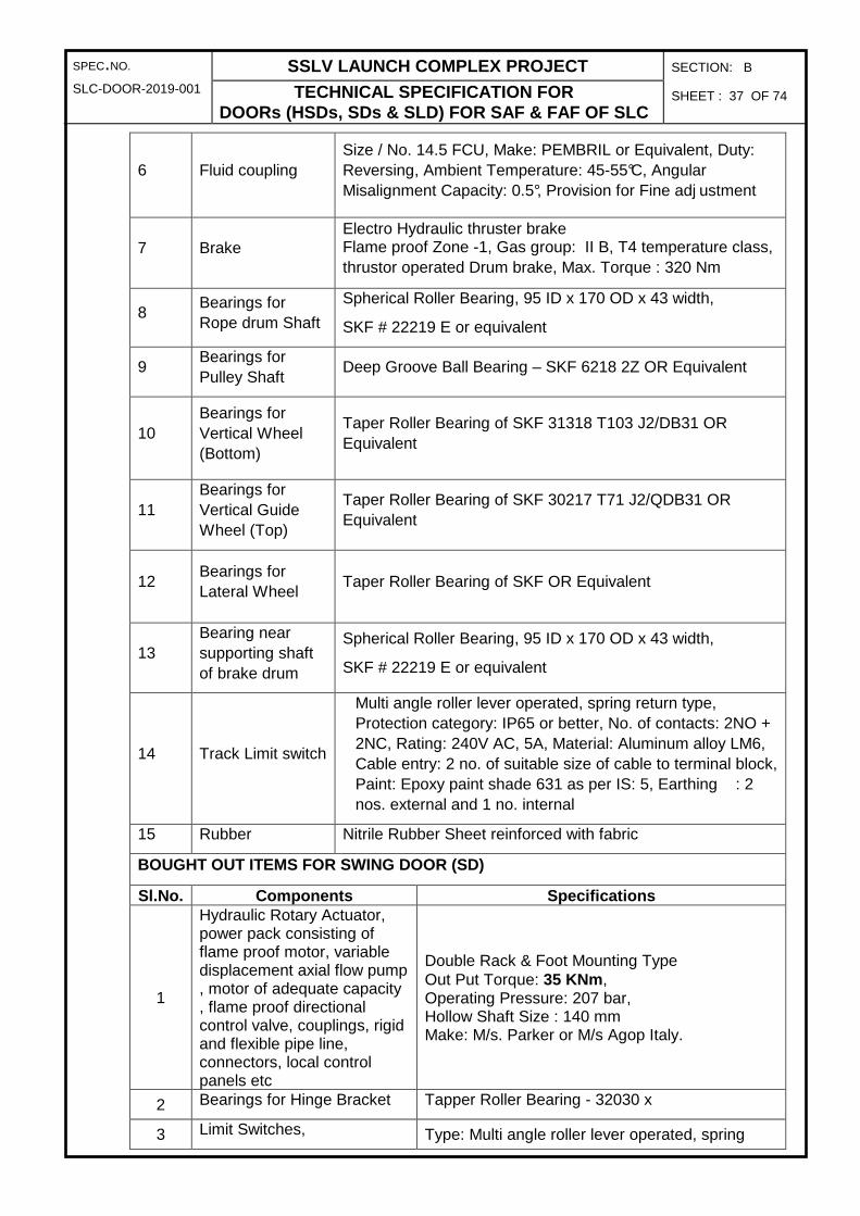
SPEC.NO. SSLV LAUNCH COMPLEX PROJECT SECTION: B
SLC-DOOR-2019-001 TECHNICAL SPECIFICATION FOR DOORs (HSDs, SDs & SLD) FOR SAF & FAF OF SLC
SHEET : 37 OF 74
6 Fluid coupling Size / No. 14.5 FCU, Make: PEMBRIL or Equivalent, Duty: Reversing, Ambient Temperature: 45-55°C, Angular Misalignment Capacity: 0.5°, Provision for Fine adj ustment
7 Brake Electro Hydraulic thruster brake Flame proof Zone -1, Gas group: II B, T4 temperature class, thrustor operated Drum brake, Max. Torque : 320 Nm
8 Bearings for Rope drum Shaft
Spherical Roller Bearing, 95 ID x 170 OD x 43 width,
SKF # 22219 E or equivalent
9 Bearings for Pulley Shaft
Deep Groove Ball Bearing – SKF 6218 2Z OR Equivalent
10 Bearings for Vertical Wheel (Bottom)
Taper Roller Bearing of SKF 31318 T103 J2/DB31 OR Equivalent
11 Bearings for Vertical Guide Wheel (Top)
Taper Roller Bearing of SKF 30217 T71 J2/QDB31 OR Equivalent
12 Bearings for Lateral Wheel
Taper Roller Bearing of SKF OR Equivalent
13 Bearing near supporting shaft of brake drum
Spherical Roller Bearing, 95 ID x 170 OD x 43 width,
SKF # 22219 E or equivalent
14 Track Limit switch
Multi angle roller lever operated, spring return type, Protection category: IP65 or better, No. of contacts: 2NO + 2NC, Rating: 240V AC, 5A, Material: Aluminum alloy LM6, Cable entry: 2 no. of suitable size of cable to terminal block, Paint: Epoxy paint shade 631 as per IS: 5, Earthing : 2 nos. external and 1 no. internal
15 Rubber Nitrile Rubber Sheet reinforced with fabric
BOUGHT OUT ITEMS FOR SWING DOOR (SD)
Sl.No. Components Specifications
1
Hydraulic Rotary Actuator, power pack consisting of flame proof motor, variable displacement axial flow pump , motor of adequate capacity , flame proof directional control valve, couplings, rigid and flexible pipe line, connectors, local control panels etc
Double Rack & Foot Mounting Type Out Put Torque: 35 KNm , Operating Pressure: 207 bar, Hollow Shaft Size : 140 mm Make: M/s. Parker or M/s Agop Italy.
2 Bearings for Hinge Bracket Tapper Roller Bearing - 32030 x
3 Limit Switches, Type: Multi angle roller lever operated, spring

SPEC.NO. SSLV LAUNCH COMPLEX PROJECT SECTION: B
SLC-DOOR-2019-001 TECHNICAL SPECIFICATION FOR DOORs (HSDs, SDs & SLD) FOR SAF & FAF OF SLC
SHEET : 38 OF 74
return type Protection Category: IP55 No. of contacts: 2 NO + 2 NC Rating: 240V AC, 5A Material: Aluminium alloy LM6 BALIGA type FLS 2115 or Equivalent
4 Rubber Nitrile Rubber Sheet reinforced with fabric
BOUGHT OUT ITEMS FOR SLIDING DOOR (SLD)
1 Flame Proof Geared Motor
Make: PBL or Equivalent Power: 0.75 KW Input Speed: 1000 RPM Output Speed: 2.11 RPM Output Torque: 3222 Nm Reduction Ratio: 435
2 Limit Switches
Type: Multi angle roller lever operated, spring return type Protection Category: IP55 No. of contacts: 2 NO + 2 NC Rating: 240V AC, 5A Material: Aluminium alloy LM6 BALIGA type FLS 2115 or Equivalent
3 Rubber Nitrile Rubber Sheet reinforced with fabric
16.0 MAKES OF BOUGHT OUT ITEMS
All bought out items shall be procured from the approved suppliers as given below:
Slno Item Makes
1 Wire ropes Usha Martin / DSR / Kiswire.
2 Selector switches and control components
Siemens / L&T/ ABB/ Schneider.
3 LED indication Lamps
Siemens / L&T/ JAI BALAJI / VAISHNO
4 Induction motors CG / BHARATH BIJILEE / HM/LHP
5 Limit Switches BALIGA / SIEMENS / ABB / L&T / Schneider / BCH /CG
6 FRLS Power and control cables
NICCO / INCAB / RPG / CCI / FINOLEX / POLYCAB / KEI / IGUS / LAPP
7 All flameproof items including Flameproof light fittings.
BALIGA / R STAHL
8 Intrinsic safe Units P&F
9 Control panels SIEMENS /ABB/L&T/ Schneider / Rittal or as approved
10 Power panels SIEMENS/ABB/L&T/ Schneider / Rittal.
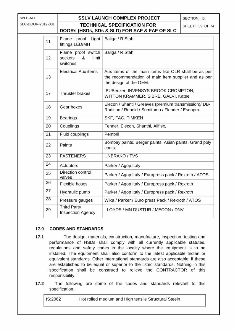
SPEC.NO. SSLV LAUNCH COMPLEX PROJECT SECTION: B
SLC-DOOR-2019-001 TECHNICAL SPECIFICATION FOR DOORs (HSDs, SDs & SLD) FOR SAF & FAF OF SLC
SHEET : 39 OF 74
11
Flame proof Light fittings LED/MH
Baliga / R Stahl
12 Flame proof switch sockets & limit switches
Baliga / R Stahl
13 Electrical Aux items Aux items of the main items like OLR shall be as per
the recommendation of main item supplier and as per the design of the OEM.
17 Thruster brakes BUBenzer, INVENSYS BROOK CROMPTON, WITTON KRAMMER, SIBRE, GALVI, Kateel
18 Gear boxes Elecon / Shanti / Greaves (premium transmission)/ DB-Radicon / Renold / Sumitomo / Flender / Esenpro.
19 Bearings SKF, FAG, TIMKEN
20 Couplings Fenner, Elecon, Shanthi, Allflex,
21 Fluid couplings Pembril
22 Paints Bombay paints, Berger paints, Asian paints, Grand poly coats.
23 FASTENERS UNBRAKO / TVS
24 Actuators Parker / Agop Italy
25 Direction control valves Parker / Agop Italy / Europress pack / Rexroth / ATOS
26 Flexible hoses Parker / Agop Italy / Europress pack / Rexroth
27 Hydraulic pump Parker / Agop Italy / Europress pack / Rexroth
28 Pressure gauges Wika / Parker / Euro press Pack / Rexroth / ATOS
29 Third Party Inspection Agency
LLOYDS / MN DUSTUR / MECON / DNV
17.0 CODES AND STANDARDS
17.1 The design, materials, construction, manufacture, inspection, testing and performance of HSDs shall comply with all currently applicable statutes, regulations and safety codes in the locality where the equipment is to be installed. The equipment shall also conform to the latest applicable Indian or equivalent standards. Other international standards are also acceptable, if these are established to be equal or superior to the listed standards. Nothing in this specification shall be construed to relieve the CONTRACTOR of this responsibility.
17.2 The following are some of the codes and standards relevant to this specification.
IS:2062 Hot rolled medium and High tensile Structural Steeln

SPEC.NO. SSLV LAUNCH COMPLEX PROJECT SECTION: B
SLC-DOOR-2019-001 TECHNICAL SPECIFICATION FOR DOORs (HSDs, SDs & SLD) FOR SAF & FAF OF SLC
SHEET : 40 OF 74
IS:1367 part13
Technical supply conditions for threaded fasteners Hot-dip galvanized coatings ( second revision)
IS:807 Code of Practice for Design, Manufacture, Erection and Testing (Structural Portion) of Cranes and Hoists.
IS:3177 Code of Practice for Design of Overhead Traveling Cranes and Gantry Cranes other than Steel Works Cranes.
IS:2062 Steel for general structural purpose.
IS:800 Code of practice for use of structural steel in general building construction.
IS:3681 Gears tooth form and modules.
IS 7403 : 1974 Code of Practice for Selection of Standard Worm and Helical Gear Boxes
IS 4460 : Parts 1 to 3 : 1995
Gears – Spur and Helical Gears – Calculation of Load Capacity
IS:1835 Steel Wires for Ropes
IS:6594 Technical supply conditions for steel wire ropes and strands.
IS:2266 Steel Wire Ropes for General Engineering Purposes.
IS:2363 Glossary of terms relating to wire ropes.
IS:3973 Selection, installation, maintenance and technical supply conditions of wire ropes.
IS:816 Code of Practice for Use of Metal Arc Welding for general Construction in Mild Steel.
IS:823 Code of Practice for Use of Metal Arc Welding of Mild Steel.
IS:1181 Qualifying Tests for Metal Arc Welders (Engaged in Welding Structures other than pipes).
IS:1323 Code of Practice for Oxy-Acetylene Welding for Structural Work in Mild steel.
IS:325 Three Phase induction Motors.
IS:4029 Guide for Testing Three Phase induction Motor.
IS:5571 Guide for selection of electrical equipment for hazardous areas
IS:5572 Classification of Hazardous Areas (Other than Mines) for electrical installations.
IS 2148 : 1981 Flameproof enclosures for electrical apparatus
IS 5780 : 1980 Specification for Intrinsically Safe Electrical Apparatus and Circuits.

SPEC.NO. SSLV LAUNCH COMPLEX PROJECT SECTION: B
SLC-DOOR-2019-001 TECHNICAL SPECIFICATION FOR DOORs (HSDs, SDs & SLD) FOR SAF & FAF OF SLC
SHEET : 41 OF 74
IS:8239
Classification of maximum surface temperature of electrical equipments for use in explosive atmosphere.
IS:1554 PVC Insulated (Heavy Duty) electric cables.
IS:2208 HRC cartridge fuse links up to 650V.
IS:2959 Contactors for voltage not exceeding 1000V AC or 1200V DC
IS:13703 Low voltage fuses for voltages not exceeding 1000V.
18.0 SPECIFIC REQUIREMENTS / INSTRUCTIONS TO BIDDERS
18.1 BIDDER’S OFFER
18.1.1 In case of any deviations from the technical specifications, the BIDDER shall indicate the same in Schedule of deviations. If no deviations are listed in the schedule of deviations, it shall be considered that the BIDDER complies in total with the technical specifications. Any deviations indicated elsewhere other than schedule of deviations in the offer will not be accepted
18.1.2 The BIDDER is advised to furnish all information called for in summary of data to be furnished along with the bid.
18.1.3 BIDDER is advised to quote for the complete scope and partial response will not be entertained. In case of few items which do not directly fall under BIDDER’s manufacturing range and / or not available from indigenous source, BIDDER should take the responsibility upon themselves to arrange to procure them and supply to ensure that their offer is complete in all respects
18.1.4 All bought out items supplied shall have capacities not less than those stated in this specification and necessary test certificates shall be furnished in this regard. However, if the BIDDER considers that higher capacity is required to meet guarantee requirements, he should offer the same and substantiate the same by calculations.
18.1.5 The BIDDER shall specify all the Design modifications which he considers are necessary for him to carry out in order to meet the guarantee requirements. The details of design modifications proposed to be carried out shall be attached as Annexure to the Schedule of Deviations from Technical Specifications.
18.1.6 Any items which may not have been specifically mentioned herein but are needed to complete the equipment / system shall also be treated as included and the same shall also be furnished and erected, unless otherwise specifically excluded as indicated.
18.1.7 All tools and tackles required during various stages of execution of order right from manufacture at shop to the erection and testing at site shall be in the scope of the Contractor.
19.0 RELIABILITY AND QUALITY ASSUARANCE PLAN
The inspection procedures shall be categorized as follows:

SPEC.NO. SSLV LAUNCH COMPLEX PROJECT SECTION: B
SLC-DOOR-2019-001 TECHNICAL SPECIFICATION FOR DOORs (HSDs, SDs & SLD) FOR SAF & FAF OF SLC
SHEET : 42 OF 74
(a) Category A: Stage wise and final inspection including review of documents by Department.
(b) Category B: Stage wise and final inspection including review of documents by the Contractor. Department shall perform final inspection and review documents.
(c) Category C: Final inspection and review of documents shall be carried out by the Contractor. Department shall carry out the final review of documents.
The minimum requirements for ensuring quality at various stages are spelt out below. However, the reliability and quality assurance plan shall be prepared by the vendor and will be reviewed and approved by Department.
The following are the basic inspection requirements to be followed upon receipt of raw material:
Review of material test certificates Category C
UT of plates for thickness greater than 50mm Category C
The following are the minimum in-process tests that shall be carried out:
Welding procedure & welder / welding operator’s performance qualification
Category C
100% MT / PT for flame cut edges for plate thickness exceeding 38mm.
Category B
100% PT after back gouging Category B
100% MT / PT for fillet welds when both plates exceed 25mm thickness.
Category A
100% MT / PT for fillet welds between tension flanges & webs. Category A
100% RT / UT for butt welds Category A
Heat treatment shall be carried out on the following:
For carbon steel plates where thickness exceeds 50 mm Category C
All other components as referred to in the drawings Category C
The following are the final inspection / tests that shall be carried out during various stages of manufacture, as applicable:
Visual and dimensional inspection of components / sub-assemblies
Category A
Blue matching for bolted components Category A
Complete assembly of HSDS at VENDOR’s shop and testing for performance requirements
Category A

SPEC.NO. SSLV LAUNCH COMPLEX PROJECT SECTION: B
SLC-DOOR-2019-001 TECHNICAL SPECIFICATION FOR DOORs (HSDs, SDs & SLD) FOR SAF & FAF OF SLC
SHEET : 43 OF 74
Complete assembly of HSDS at site and testing for performance requirements.
Category A
The schedule of tests stated above is indicative and not exhaustive in nature. CONTRACTOR shall carry out any other tests at shop / site as per directions of PURCHASER.
20.0 INSPECTION AND TESTING PROCEDURES AND SCOPE OF INSPECTION
20.1 Raw Material Inspection shall be carried out at the Vendor’s works for compliance of the raw materials to the specified standards.
20.2 Bought out components shall be inspected either at Vendor’s works or at the Sub-contractor’s premises for compliance with the Specifications.
20.3 Fabricated components shall be inspected at the Vendor’s works for compliance with the component drawings. Sub-Assemblies shall be inspected at the Vendor’s works for compliance with the Sub-Assembly drawings and for performance requirements. Also, full Assembly of the HSDS shall be inspected at Vendor’s works after shop assembly for compliance with assembly drawings and performance requirements.
20.4 Full Assembly of the HSD shall be inspected at Purchaser’s premises after site assembly for compliance with the Assembly Drawings and performance requirements.
20.5 After the award of contract, CONTRACTOR shall prepare detailed Quality Assurance Plan (QAP) for inspection & testing of all subassemblies / components of the HSDs. The QAP shall be reviewed and approved by the Third Party Inspection Agency and the PURCHASER. Indicative QAPs for HSDS are enclosed in Section D of this specification
20.6 The procedure to be followed for testing the accuracy requirements for HSDs shall be as specified by the PURCHASER
20.7 All measuring and testing instruments / equipment required for carrying out all tests at VENDOR’s works and at PURCHASER’s site shall be provided by the Contractor.
20.8 CONTRACTOR shall furnish calibration certificates for the instruments to be used for testing at shop and site. The calibration certificates furnished by the CONTRACTOR shall not be more than 12 months old.
20.9 TESTING
20.10 HSDs mainly comprises of drive mechanism and door structure (door leaf) from the point of view of testing. In order to realise successful operation of the door following testing activities shall be performed
20.10.1 Testing at Manufacturer’s works
a) Drive System (No load)
No load run test shall be carried out for the fully assembled gear box continuously for minimum 1 hour.
The drive mechanism shall be completely assembled at manufacturer’s works
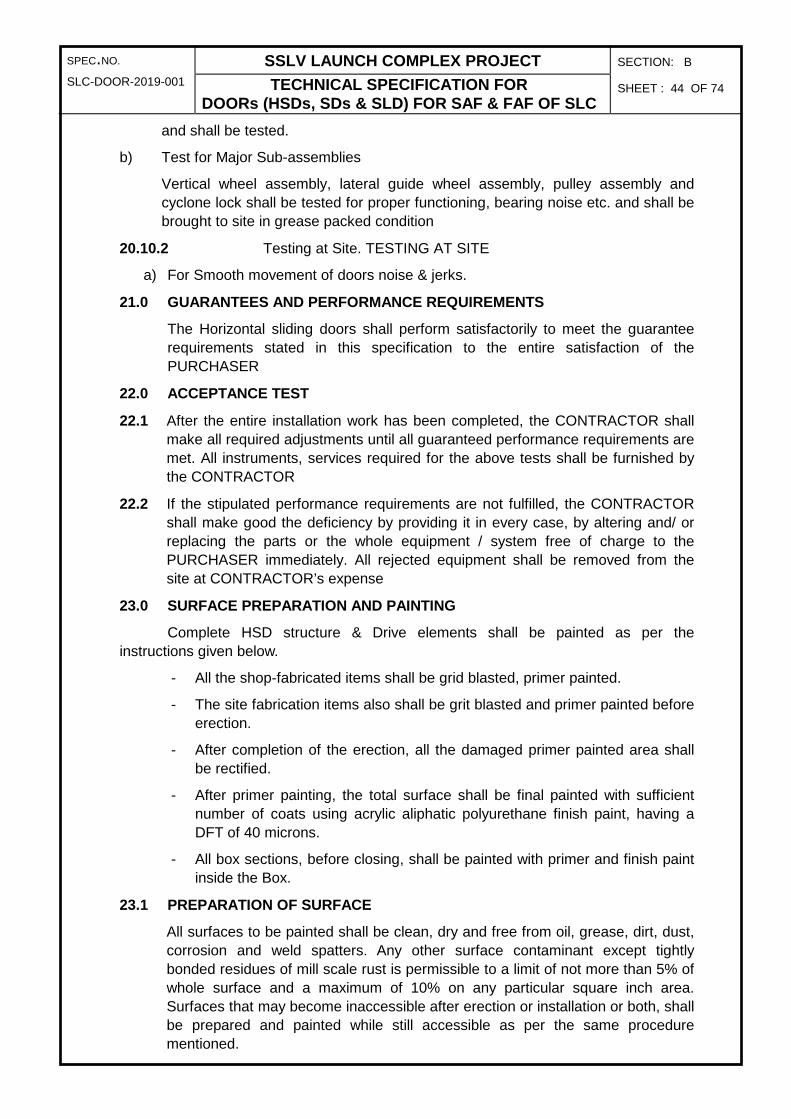
SPEC.NO. SSLV LAUNCH COMPLEX PROJECT SECTION: B
SLC-DOOR-2019-001 TECHNICAL SPECIFICATION FOR DOORs (HSDs, SDs & SLD) FOR SAF & FAF OF SLC
SHEET : 44 OF 74
and shall be tested.
b) Test for Major Sub-assemblies
Vertical wheel assembly, lateral guide wheel assembly, pulley assembly and cyclone lock shall be tested for proper functioning, bearing noise etc. and shall be brought to site in grease packed condition
20.10.2 Testing at Site. TESTING AT SITE
a) For Smooth movement of doors noise & jerks.
21.0 GUARANTEES AND PERFORMANCE REQUIREMENTS
The Horizontal sliding doors shall perform satisfactorily to meet the guarantee requirements stated in this specification to the entire satisfaction of the PURCHASER
22.0 ACCEPTANCE TEST
22.1 After the entire installation work has been completed, the CONTRACTOR shall make all required adjustments until all guaranteed performance requirements are met. All instruments, services required for the above tests shall be furnished by the CONTRACTOR
22.2 If the stipulated performance requirements are not fulfilled, the CONTRACTOR shall make good the deficiency by providing it in every case, by altering and/ or replacing the parts or the whole equipment / system free of charge to the PURCHASER immediately. All rejected equipment shall be removed from the site at CONTRACTOR’s expense
23.0 SURFACE PREPARATION AND PAINTING
Complete HSD structure & Drive elements shall be painted as per the instructions given below.
- All the shop-fabricated items shall be grid blasted, primer painted.
- The site fabrication items also shall be grit blasted and primer painted before erection.
- After completion of the erection, all the damaged primer painted area shall be rectified.
- After primer painting, the total surface shall be final painted with sufficient number of coats using acrylic aliphatic polyurethane finish paint, having a DFT of 40 microns.
- All box sections, before closing, shall be painted with primer and finish paint inside the Box.
23.1 PREPARATION OF SURFACE
All surfaces to be painted shall be clean, dry and free from oil, grease, dirt, dust, corrosion and weld spatters. Any other surface contaminant except tightly bonded residues of mill scale rust is permissible to a limit of not more than 5% of whole surface and a maximum of 10% on any particular square inch area. Surfaces that may become inaccessible after erection or installation or both, shall be prepared and painted while still accessible as per the same procedure mentioned.

SPEC.NO. SSLV LAUNCH COMPLEX PROJECT SECTION: B
SLC-DOOR-2019-001 TECHNICAL SPECIFICATION FOR DOORs (HSDs, SDs & SLD) FOR SAF & FAF OF SLC
SHEET : 45 OF 74
23.2 GRIT BLASTING
The entire surface of all the fabricated materials is to be grid blasted as per near white quality of steel structures painting council (SSPC) standard of SA 2.5 of SIS 055900. The surface profile after blasting shall be between 37-65 microns and should be of jagged in nature.
Hand cleaning by chipping and scraping followed by wire brushing / abrasive wheels is allowed for items where surface preparation is difficult by sand blasting after taking approvals from purchaser / TPIA. All surfaces shall be degreased using a suitable solvent to remove oil & grease and shall be dried off before painting
23.3 PAINTING SCHEME
Immediately after grit blasting, one coat of inorganic zinc silicate primer shall be applied to a dry film thickness (DFT) of 65 microns (minimum), followed by a final coat of 40 microns of acrylic aliphatic polyurethane finish paint. Colour code will be finalized by purchaser after award of contract.
All paint and primer shall be of standard quality and procured from approved manufacturers. The tenderer shall provide “Elcometer” / Paint thickness measuring gauges free of charge and shall measure the thickness of paint in the presence of the representative of the purchaser at random locations selected by him.
Machine finished surfaces shall be protected against corrosion by a rust inhibiting coating that can be easily removed prior to erection or which has characteristics that make removal unnecessary prior to erection.
Field painting shall only be done after the structure is erected, levelled, plumbed, aligned and welded / connected in its final position, tested and commissioned. However, touch-up painting for making good to any damaged shop painting and completing any unfinished portion of the shop coat shall be carried out by the Tenderer at free of cost. The materials and specification for such painting in the field shall be in accordance with the requirements of the specification for shop painting.
Painting shall not be done in frosty or foggy weather or when humidity is such as to cause condensation on the surfaces to be painted. Before painting of steel, which is delivered unpainted, is commenced, all surfaces to be painted shall be dried and thoroughly cleaned from all loose scale and rust.
All field rivets, bolts, welds and abrasions to the shop coat shall be spot painted with the same paint used for the shop coat. Where specified, surfaces which will be in contact after site assembling shall receive a coat of paint (in addition to the shop coat, if any) and shall be brought together while the paint is still wet.
Bolts and fabricated steel members, which are galvanized or otherwise treated, shall not be painted.
Paints shall be stored under cover in airtight containers. Paints supplied in sealed containers shall be used as soon as possible once the container is opened. Paints shall be checked for shelf life to meet the requirements before application. Proper action shall be taken well in advance prior to actual usage.
While painting the new structures, the already finished floors and structures shall

SPEC.NO. SSLV LAUNCH COMPLEX PROJECT SECTION: B
SLC-DOOR-2019-001 TECHNICAL SPECIFICATION FOR DOORs (HSDs, SDs & SLD) FOR SAF & FAF OF SLC
SHEET : 46 OF 74
not be spoilt. If there is any spillage of paint on the floors or members on the finished structures, the tenderer has to clear and provide the painting to the spoiled areas.
23.4 Paint Specifications
a) Inorganic Zinc Silicate Primer:
• Two part, self-cured
• Dry temperature resistance to 400 oC
• Minimum shelf life of 12 months
• Excellent abrasion resistance
• Minimum coverage of 9 sq m./litre at 65 microns (minimum)
• Volume of solids 60% (min) by weight and 80% of zinc in dry film by weight
• No mud cracking at an applied thickness of 75 microns.
(b) Air drying Acrylic Aliphatic polyurethane finish paint.
• As per approved manufacturer’s specifications.
• Colour code will be finalised by department after award of contract.
24.0 START-UP SPARES & MAINTENANCE TOOLS
24.1 The BIDDER shall include in start-up Spares & Maintenance tools in his scope.
24.2 The spares supplied shall be directly interchangeable with parts for which they are intended for replacement.
24.3 The spares shall be treated and packed for long storage (minimum 5 years) under the climatic conditions prevailing at the site.
24.4 The BIDDER shall indicate the service expectancy periods for all the spare parts in terms of hours of operation under normal operating conditions after which replacement will become necessary.
24.5 The Start-Up Spares are those spares which will be required during start-up and commissioning of the equipment / systems until the equipment/systems are handed over to the SLC after completion of performance testing.
24.6 The prices of the Start-Up Spares and tools shall be included in the lumpsum supply price of the total system. An adequate stock of Start-Up Spares and maintenance tools shall be available at the site such that the start-up and commissioning of the equipment / systems, performance testing and handing over the equipment/ systems to the SLC can be carried out without hindrance or delay.
24.7 All Start-Up Spares which remain unused after the taking over the plant shall remain the property of the SLC. BIDDER’s quoted lumpsum price for the supply of the bought-out items shall be inclusive of the cost of Start-Up Spares.
24.8 Following are the list of minimum number of start-up spares for HSD to be included in the BIDDER’s scope.

SPEC.NO. SSLV LAUNCH COMPLEX PROJECT SECTION: B
SLC-DOOR-2019-001 TECHNICAL SPECIFICATION FOR DOORs (HSDs, SDs & SLD) FOR SAF & FAF OF SLC
SHEET : 47 OF 74
Sl.no Description Quantity
MECHANICAL SPARES
1 Linings for Brakes 2 Pairs
2 Oil Seals for each Fluid couplings 1 Sets
3 Oil Seals for each Gear box 1 Sets
5 Set of Gaskets of all sizes wherever applicable 3 sets
ELECTRICAL SPARES
5 Fuse links 3 no.s each category.
6 Power Contactors 1 no. minimum or 10% of total qty.
7 Push buttons 4 no. minimum or 10% of total qty.
8 Limit Switches 2 Nos
9 Spare LCP ready to replace at site. 2 Nos
25.0 TENDER EVALUATION AND PENALITY FACTOR
25.1 The BIDDER shall comply with all systems / parameters specified in section B, C, D, E &F
25.2 Deviation from the specifications, if acceptable to the PURCHASER insofar as practicable will be converted to rupee value and added to the bid price to compensate for the deviation from the specification. In determining the rupee value of the deviations, the PURCHASER will use the parameters consistent with those specific in the documents and specifications and other information as necessary and available to the PURCHASER
26.0 DATA TO BE FURNISHED AFTER AWARD OF CONTRACT
The BIDDER shall ensure the following documentation are prepared and submitted to PURCHASER for his review / record
26.1 Schedule of Assembly & Detailed drawings and documents to be submitted for review & approval with submission dates.
26.2 Quality Assurance Plan (QAP).
26.3 Bar chart for supply & erection schedule indicating the date of completion of various activities so as to complete execution of the contract within the time frame stipulated in the LOI / Purchase order.
26.4 Progress reports
26.5 Instrument data sheets.
26.6 Electrical wiring diagrams showing interlocks, controls, wiring sizes, rating of each electrical component etc. and logic diagrams.

SPEC.NO. SSLV LAUNCH COMPLEX PROJECT SECTION: B
SLC-DOOR-2019-001 TECHNICAL SPECIFICATION FOR DOORs (HSDs, SDs & SLD) FOR SAF & FAF OF SLC
SHEET : 48 OF 74
26.7 Dimensioned general arrangement and section drawings of control and instrumentation panels and switchgear panel.
26.8 Detailed description of operating sequence and control and interlock system.
26.9 Erection, start-up, operation and maintenance manual complete with lubrication schedule etc.
26.10 As-built drawings
26.11 Quality Assurance documentation compiled for the project.
26.12 The above list of documents is indicative and not exhaustive. The BIDDER / CONTRACTOR shall submit documents as specified in various sections of this specification and also as per the specific instructions of the PURCHASER.
27.0 FINAL DOCUMENTS
CONTRACTOR shall submit the copies of operation and maintenance manuals well before the despatch of the equipment. The manual shall be in sufficient detail with step by step instructions to enable others to inspect, erect, commission, maintain, dismantle, repair, reassemble and adjust all parts of the equipment. Each manual shall also include a complete set of approved as built drawings together with performance / rating curves / charts of the equipment, maintenance schedule and test certificates wherever applicable.
CONTRACTOR shall submit all the raw material test certificates, Ultrasonic testing of the raw material, Ultrasonic / radiography test certificates of all necessary welds. Stress relieving charts, Hardness test certificates and Dimensional inspection reports of individual components. Quality assurance documentation compiled for the project.

SP
EC
.NO
. S
SL
V L
AU
NC
H C
OM
PL
EX
PR
OJE
CT
S
EC
TIO
N:
C1
TC
E-7
517A
-D-8
58-0
01
BIL
L O
F M
AT
ER
IAL
FO
R H
SD F
OR
SA
F &
FA
F O
F S
LC
S
HE
ET
: 1
OF
13
T
CE
FO
RM
NO
. 329
R5
BIL
L O
F M
AT
ER
IAL
S
DE
TA
ILS
OF
FA
BR
ICA
TE
D C
OM
PO
NE
NT
S
Mat
eria
l Qua
ntiti
es m
entio
ned
in th
e fo
llow
ing
Tab
le is
for
1 no
. of D
oor
leaf
onl
y. E
ach
HS
D c
ompr
ises
2 le
aves
, driv
e ar
rang
emen
t and
oth
er
asse
mbl
ies.
SA
F h
ave
2 no
s H
SD
s an
d F
AF
hav
e 1
no H
SD
.
Hen
ce, q
uan
titi
es o
f 6
leav
es s
hal
l be
con
sid
ered
fo
r ca
lcu
lati
ng
To
tal M
ater
ial Q
uan
titi
es o
f H
SD
s.
Sl
No
. D
ES
CR
IPT
ION
OF
C
OM
PO
NE
NT
Q
TY
. O
VE
RA
LL
DIM
EN
SIO
NS
(m
m)
PA
RT
N
O.
MA
TE
RIA
L
AP
PR
OX
. W
EIG
HT
HE
AT
T
RE
AT
ME
NT
/ R
EM
AR
KS
1.0
Do
or
Lea
f
1.1
Pla
te
1 19
00 x
900
x 2
0 (T
hk.)
Mild
Ste
el E
250
-BR
; IS
:206
2 26
8 kg
1.2
Pla
te
1 19
00 x
900
x 2
0 (T
hk.)
Mild
Ste
el E
250
-BR
; IS
:206
2 26
8 kg
1.3
Pla
te
1 86
0 x
530
x 36
(T
hk.)
Mild
Ste
el E
250
-BR
; IS
:206
2 12
9 kg
1.4
Stif
fene
r 2
460
x 34
1 x
12 (
Thk
.)
M
ild S
teel
E 2
50-B
R; I
S:2
062
30 k
g
1.5
Stif
fene
r 2
565
x 46
0 x
12 (
Thk
.)
M
ild S
teel
E 2
50-B
R; I
S:2
062
49 k
g
1.6
Stif
fene
r 1
807
x 46
0 x
12 (
Thk
.)
M
ild S
teel
E 2
50-B
R; I
S:2
062
35 k
g
1.7
Stif
fene
r 3
900
x 46
0 x
12 (
Thk
.)
M
ild S
teel
E 2
50-B
R; I
S:2
062
117
kg
1.8
Pla
te
1 11
90 x
560
x 2
0 (T
hk.)
Mild
Ste
el E
250
-BR
; IS
:206
2 10
5 kg
1.9
Pla
te
1 11
90 x
560
x 2
0 (T
hk.)
Mild
Ste
el E
250
-BR
; IS
:206
2 10
5 kg
1.10
P
late
1
575
x 53
0 x
36 (
Thk
.)
M
ild S
teel
E 2
50-B
R; I
S:2
062
86 k
g
1.11
S
tiffe
ner
3 56
0 x
460
x 12
(T
hk.)
Mild
Ste
el E
250
-BR
; IS
:206
2 73
kg
1.12
S
tiffe
ner
2 46
0 x
434
x 12
(T
hk.)
Mild
Ste
el E
250
-BR
; IS
:206
2 38
kg

SP
EC
.NO
. S
SL
V L
AU
NC
H C
OM
PL
EX
PR
OJE
CT
S
EC
TIO
N:
C1
TC
E-7
517A
-D-8
58-0
01
BIL
L O
F M
AT
ER
IAL
FO
R H
SD F
OR
SA
F &
FA
F O
F S
LC
S
HE
ET
: 2
OF
13
T
CE
FO
RM
NO
. 329
R5
Sl
No
. D
ES
CR
IPT
ION
OF
C
OM
PO
NE
NT
Q
TY
. O
VE
RA
LL
DIM
EN
SIO
NS
(m
m)
PA
RT
N
O.
MA
TE
RIA
L
AP
PR
OX
. W
EIG
HT
HE
AT
T
RE
AT
ME
NT
/ R
EM
AR
KS
1.13
IS
MB
500
2
IS
MB
500
x 1
1980
Lg.
IS:8
08
2082
kg
1.14
P
late
2
1168
0 x
300
x 20
(T
hk.)
Mild
Ste
el E
250
-BR
; IS
:206
2 11
00 k
g
1.15
S
tiffe
ner
40
460
x 78
x 1
2 (T
hk.)
Mild
Ste
el E
250
-BR
; IS
:206
2 13
5 kg
1.16
IS
MB
500
1
ISM
B 5
00 x
520
0 Lg
.
IS:8
08
452
kg
1.17
IS
MB
500
1
ISM
B 5
00 x
546
0 Lg
.
IS:8
08
474
kg
1.18
IS
MB
500
2
ISM
B 5
00 x
740
Lg.
IS:8
08
129
kg
1.18
A
ISM
B 5
00
1 IS
MB
500
x 5
750
Lg.
IS
:808
50
0 kg
1.18
B
ISM
B 5
00
1 IS
MB
500
x 5
490
Lg.
IS
:808
47
7 kg
1.19
W
eb P
late
2
11
980
x 76
0 x
10 (
Thk
.)
M
ild S
teel
E 2
50-B
R; I
S:2
062
1429
kg
1.20
P
late
2
1240
x 4
68 x
12
(Thk
.)
M
ild S
teel
E 2
50-B
R; I
S:2
062
109
kg
1.21
P
late
4
1090
x 1
00 x
16
(Thk
.)
M
ild S
teel
E 2
50-B
R; I
S:2
062
55 k
g
1.22
T
rack
Pla
te
1
1200
0 x
150
x 10
(T
hk.)
Mild
Ste
el E
250
-BR
; IS
:206
2 14
1 kg
1.23
P
late
2
1200
0 x
240
x 16
(T
hk.)
Mild
Ste
el E
250
-BR
; IS
:206
2 72
3 kg
1.24
P
late
1
1200
0 x
168
x 10
(T
hk.)
Mild
Ste
el E
250
-BR
; IS
:206
2 15
8 kg
1.25
P
late
10
24
0 x
190
x 16
(T
hk.)
Mild
Ste
el E
250
-BR
; IS
:206
2 57
kg
1.26
P
late
10
24
0 x
195
x 16
(T
hk.)
Mild
Ste
el E
250
-BR
; IS
:206
2 59
kg
1.27
S
tiffe
ner
10
435
x 15
0 x
8 (T
hk.)
Mild
Ste
el E
250
-BR
; IS
:206
2 41
kg

SP
EC
.NO
. S
SL
V L
AU
NC
H C
OM
PL
EX
PR
OJE
CT
S
EC
TIO
N:
C1
TC
E-7
517A
-D-8
58-0
01
BIL
L O
F M
AT
ER
IAL
FO
R H
SD F
OR
SA
F &
FA
F O
F S
LC
S
HE
ET
: 3
OF
13
T
CE
FO
RM
NO
. 329
R5
Sl
No
. D
ES
CR
IPT
ION
OF
C
OM
PO
NE
NT
Q
TY
. O
VE
RA
LL
DIM
EN
SIO
NS
(m
m)
PA
RT
N
O.
MA
TE
RIA
L
AP
PR
OX
. W
EIG
HT
HE
AT
T
RE
AT
ME
NT
/ R
EM
AR
KS
1.28
S
tiffe
ner
10
168
x 30
4 x
12 (
Thk
.)
M
ild S
teel
E 2
50-B
R; I
S:2
062
48 k
g
1.29
P
late
10
16
8 x
309
x 12
(T
hk.)
Mild
Ste
el E
250
-BR
; IS
:206
2 49
kg
1.30
P
late
20
46
0 x
150
x 12
(T
hk.)
Mild
Ste
el E
250
-BR
; IS
:206
2 13
0 kg
1.31
P
late
2
734
x 46
8 x
12 (
Thk
.)
M
ild S
teel
E 2
50-B
R; I
S:2
062
65 k
g
1.32
P
late
4
440
x 10
0 x
16 (
Thk
.)
M
ild S
teel
E 2
50-B
R; I
S:2
062
22 k
g
1.33
P
late
2
1168
0 x
150
x 20
(T
hk.)
Mild
Ste
el E
250
-BR
; IS
:206
2 55
0 kg
1.34
P
late
2
1200
0 x
500
x 10
(T
hk.)
Mild
Ste
el E
250
-BR
; IS
:206
2 94
2 kg
1.35
P
late
2
8980
x 1
50 x
10
(Thk
.)
M
ild S
teel
E 2
50-B
R; I
S:2
062
211
kg
1.36
P
late
2
8980
x 8
00 x
10
(Thk
.)
M
ild S
teel
E 2
50-B
R; I
S:2
062
1128
kg
1.37
IS
MB
500
2
ISM
B 5
00 x
898
0 Lg
.
IS:8
08
1561
kg
1.38
T
op &
Bot
tom
Cov
er
She
et
2 12
000
x 90
00 x
3.1
5 (T
hk.)
Mild
Ste
el E
250
-BR
; IS
:206
2 53
42 k
g
1.39
IS
MB
100
9
ISM
B 1
00 x
898
0 Lg
.
IS:8
08
744
kg
1.40
IS
A 5
0
90
ISA
50
x 50
x 6
Thi
ck -
100
0Lg.
IS:8
08
405
kg
1.41
P
late
90
20
0 x
200
x 10
(T
hk.)
Mild
Ste
el E
250
-BR
; IS
:206
2 28
3 kg
1.42
G
uide
Cha
nnel
-1
4 47
0 x
1200
0 x
12 (
Thk
.)
M
ild S
teel
E 2
50-B
R; I
S:2
062
2125
kg
1.43
G
uide
Cha
nnel
-2
4 28
1 x
1200
0 x
10 (
Thk
.)
M
ild S
teel
E 2
50-B
R; I
S:2
062
1059
kg
1.44
G
uide
Cha
nnel
-3
4 16
2 x
1200
0 x
22 (
Thk
.)
M
ild S
teel
E 2
50-B
R; I
S:2
062
1343
kg

SP
EC
.NO
. S
SL
V L
AU
NC
H C
OM
PL
EX
PR
OJE
CT
S
EC
TIO
N:
C1
TC
E-7
517A
-D-8
58-0
01
BIL
L O
F M
AT
ER
IAL
FO
R H
SD F
OR
SA
F &
FA
F O
F S
LC
S
HE
ET
: 4
OF
13
T
CE
FO
RM
NO
. 329
R5
Sl
No
. D
ES
CR
IPT
ION
OF
C
OM
PO
NE
NT
Q
TY
. O
VE
RA
LL
DIM
EN
SIO
NS
(m
m)
PA
RT
N
O.
MA
TE
RIA
L
AP
PR
OX
. W
EIG
HT
HE
AT
T
RE
AT
ME
NT
/ R
EM
AR
KS
2.0
Ver
tica
l Wh
eel a
nd
Ver
tica
l Gu
ide
Wh
eel A
ssem
bly
( 2
nos
Ver
tical
Whe
el a
nd V
ertic
al G
uide
Whe
el S
hall
be c
onsi
dere
d fo
r ea
ch H
SD
leaf
)
2.1
Axl
e of
Whe
el
2 Ø
100
x 2
85 L
g
C55
Mn7
5 36
kg
2.2
Tap
per
Rol
ler
Bea
ring
4 30
217
T71
J2/
QD
B31
SK
F/E
qui
2.3
Whe
el
2 Ø
280
x 1
10 W
idth
C55
Mn7
5 10
6 kg
2.4
Spa
cer
2 O
D 1
00 x
ID 8
0 x
33.5
Thi
ck
M
ild S
teel
E 2
50-B
R; I
S:2
062
2 kg
2.5
Spa
cer
4 O
D 2
10 x
ID 1
01.5
x 2
6 T
hick
Mild
Ste
el E
250
-BR
; IS
:206
2 22
kg
2.6
Bea
ring
Lock
Nut
&
Lock
Was
her
2 K
M 1
5 , M
B 1
5
SK
F/E
qui
2.7
Gre
ase
Nip
ple
5 A
P ¼
” –
MS
339
2.8
Kee
per
Pla
te
5 40
x14
0 x1
0 T
hick
Mild
Ste
el E
250
-BR
; IS
:206
2 4
kg
2.9
Bra
cket
for
Whe
el
1 Ø
400
(S
ingl
e W
heel
)
Mild
Ste
el E
250
-BR
; IS
:206
2 30
1 kg
2.10
A
xle
3 Ø
110
x 4
10 L
g
C55
Mn7
5 92
kg
2.11
T
appe
r R
olle
r B
earin
g 6
3131
8 T
103
J2/D
B31
SK
F/E
qui
2.12
S
pace
r 3
OD
110
x ID
85
x 45
.5 T
hick
30
1 kg
2.1A
B
otto
m B
rack
et
1 Ø
400
(D
oubl
e W
heel
)
Mild
Ste
el E
250
-BR
; IS
:206
2 4
kg
2.2A
T
op B
rack
et
1 Ø
400
(D
oubl
e W
heel
)
Mild
Ste
el E
250
-BR
; IS
:206
2
2127
kg
2.10
A
Whe
el
3 O
D 4
00 x
ID 1
90 x
160
Thi
ck
C
55M
n75
Rim
har
dnes
s be
twee
n 30
0 to
35
0 B
HN
& d
epth
of
har
dnes
s up
to

SP
EC
.NO
. S
SL
V L
AU
NC
H C
OM
PL
EX
PR
OJE
CT
S
EC
TIO
N:
C1
TC
E-7
517A
-D-8
58-0
01
BIL
L O
F M
AT
ER
IAL
FO
R H
SD F
OR
SA
F &
FA
F O
F S
LC
S
HE
ET
: 5
OF
13
T
CE
FO
RM
NO
. 329
R5
Sl
No
. D
ES
CR
IPT
ION
OF
C
OM
PO
NE
NT
Q
TY
. O
VE
RA
LL
DIM
EN
SIO
NS
(m
m)
PA
RT
N
O.
MA
TE
RIA
L
AP
PR
OX
. W
EIG
HT
HE
AT
T
RE
AT
ME
NT
/ R
EM
AR
KS
10
mm
.
2.11
A
Bea
ring
Ret
aine
r
6 O
D 2
55 x
ID 1
12 x
45
Thi
ck
M
ild S
teel
E 2
50-B
R; I
S:2
062
2.12
A
Bus
h
1 O
D 1
30 x
ID 1
10 x
130
Thi
ck
M
ild S
teel
E 2
50-B
R; I
S:2
062
2.13
A
Bra
cket
1
Top
Ver
tical
Whe
el
M
ild S
teel
E 2
50-B
R; I
S:2
062
3.0
Ho
rizo
nta
l Gu
ide
Wh
eel D
etai
ls (
2 n
os H
oriz
onta
l Gui
de W
heel
Sha
ll be
con
side
red
for
each
HS
D le
af)
3.1
Pla
te
4 65
0 x
560
x 45
(T
hk.)
Mild
Ste
el E
250
-BR
; IS
:206
2 51
4 kg
3.2
Pla
te
4 52
0 x
398
x 85
(T
hk.)
Mild
Ste
el E
250
-BR
; IS
:206
2 55
2 kg
3.3
Bus
h 8
OD
175
x ID
130
x 1
0 T
hick
Mild
Ste
el E
250
-BR
; IS
:206
2 7
kg
3.4
Stif
fene
r 16
17
0 x
75 x
25
(Thk
.)
M
ild S
teel
E 2
50-B
R; I
S:2
062
40 k
g
3.5
Gui
de W
heel
4
OD
280
x ID
150
x 1
10 T
hick
C55
Mn7
5 16
7kg
Rim
har
dnes
s be
twee
n 30
0 to
35
0 B
HN
& d
epth
of
har
dnes
s up
to
10m
m.
3.6
Pla
te
4 10
10 x
610
x 6
0 (T
hk.)
Mild
Ste
el E
250
-BR
; IS
:206
2 11
61 k
g
3.7
Pla
te
4 65
0 x
560
x 45
(T
hk.)
Mild
Ste
el E
250
-BR
; IS
:206
2 51
4 kg
3.8
Pla
te
4 56
0 x
90 x
85
(Thk
.)
M
ild S
teel
E 2
50-B
R; I
S:2
062
135
kg
3.9
Pla
te
24
90 x
90
x 10
(T
hk.)
Mild
Ste
el E
250
-BR
; IS
:206
2 15
kg
3.10
S
tiffe
ner
16
283
x 90
x 4
0 (T
hk.)
Mild
Ste
el E
250
-BR
; IS
:206
2 12
8 kg
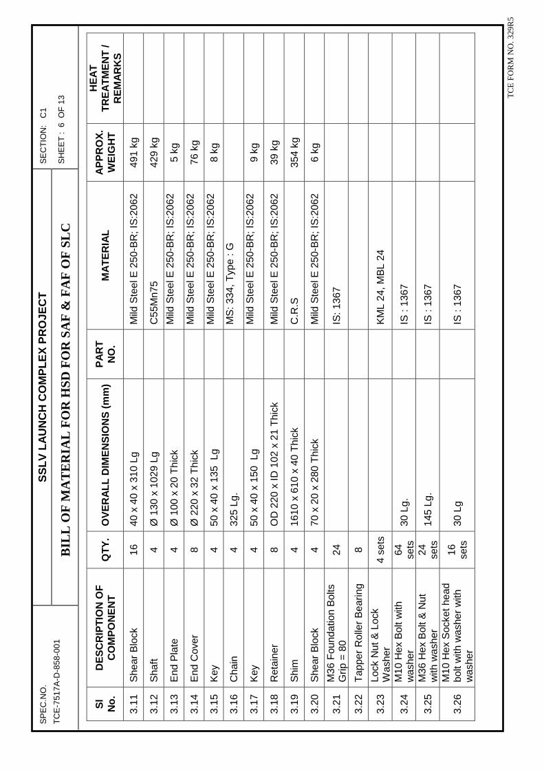
SP
EC
.NO
. S
SL
V L
AU
NC
H C
OM
PL
EX
PR
OJE
CT
S
EC
TIO
N:
C1
TC
E-7
517A
-D-8
58-0
01
BIL
L O
F M
AT
ER
IAL
FO
R H
SD F
OR
SA
F &
FA
F O
F S
LC
S
HE
ET
: 6
OF
13
T
CE
FO
RM
NO
. 329
R5
Sl
No
. D
ES
CR
IPT
ION
OF
C
OM
PO
NE
NT
Q
TY
. O
VE
RA
LL
DIM
EN
SIO
NS
(m
m)
PA
RT
N
O.
MA
TE
RIA
L
AP
PR
OX
. W
EIG
HT
HE
AT
T
RE
AT
ME
NT
/ R
EM
AR
KS
3.11
S
hear
Blo
ck
16
40 x
40
x 31
0 Lg
Mild
Ste
el E
250
-BR
; IS
:206
2 49
1 kg
3.12
S
haft
4
Ø 1
30 x
102
9 Lg
C55
Mn7
5 42
9 kg
3.13
E
nd P
late
4
Ø 1
00 x
20
Thi
ck
M
ild S
teel
E 2
50-B
R; I
S:2
062
5 kg
3.14
E
nd C
over
8
Ø 2
20 x
32
Thi
ck
M
ild S
teel
E 2
50-B
R; I
S:2
062
76 k
g
3.15
K
ey
4 50
x 4
0 x
135
Lg
M
ild S
teel
E 2
50-B
R; I
S:2
062
8 kg
3.16
C
hain
4
325
Lg.
M
S: 3
34, T
ype
: G
3.17
K
ey
4 50
x 4
0 x
150
Lg
M
ild S
teel
E 2
50-B
R; I
S:2
062
9 kg
3.18
R
etai
ner
8 O
D 2
20 x
ID 1
02 x
21
Thi
ck
M
ild S
teel
E 2
50-B
R; I
S:2
062
39 k
g
3.19
S
him
4
1610
x 6
10 x
40
Thi
ck
C
.R.S
35
4 kg
3.20
S
hear
Blo
ck
4 70
x 2
0 x
280
Thi
ck
M
ild S
teel
E 2
50-B
R; I
S:2
062
6 kg
3.21
M
36 F
ound
atio
n B
olts
G
rip =
80
24
IS: 1
367
3.22
T
appe
r R
olle
r B
earin
g 8
3.23
Lo
ck N
ut &
Loc
k W
ashe
r 4
sets
K
ML
24, M
BL
24
3.24
M
10 H
ex B
olt w
ith
was
her
64
sets
30
Lg.
IS :
1367
3.25
M
36 H
ex B
olt &
Nut
w
ith w
ashe
r 24
se
ts
145
Lg.
IS
: 13
67
3.26
M
10 H
ex S
ocke
t hea
d bo
lt w
ith w
ashe
r w
ith
was
her
16
sets
30
Lg
IS
: 13
67

SP
EC
.NO
. S
SL
V L
AU
NC
H C
OM
PL
EX
PR
OJE
CT
S
EC
TIO
N:
C1
TC
E-7
517A
-D-8
58-0
01
BIL
L O
F M
AT
ER
IAL
FO
R H
SD F
OR
SA
F &
FA
F O
F S
LC
S
HE
ET
: 7
OF
13
T
CE
FO
RM
NO
. 329
R5
Sl
No
. D
ES
CR
IPT
ION
OF
C
OM
PO
NE
NT
Q
TY
. O
VE
RA
LL
DIM
EN
SIO
NS
(m
m)
PA
RT
N
O.
MA
TE
RIA
L
AP
PR
OX
. W
EIG
HT
HE
AT
T
RE
AT
ME
NT
/ R
EM
AR
KS
3.27
M
8 H
ex S
crew
with
S
prin
g w
ashe
r 32
se
ts
30 L
g
IS :
1367
4.0
Cyc
lon
e L
ock
Ass
emb
ly (
4 n
os C
yclo
ne lo
ck S
hall
be c
onsi
dere
d fo
r ea
ch H
SD
leaf
)
4.1
Bra
cket
1
Mild
Ste
el E
250
-BR
; IS
:206
2 13
4 kg
4.2
She
ar B
lock
4
420
x 30
x 3
0 T
hick
Mild
Ste
el E
250
-BR
; IS
:206
2 12
kg
4.3
Pla
te
12
Ø 4
00 x
140
(W
)
Mild
Ste
el E
250
-BR
; IS
:206
2 10
kg
4.4
Cap
2
Ø 1
50 x
410
Lg.
Mild
Ste
el E
250
-BR
; IS
:206
2 40
kg
4.5
Cou
pler
1
120
(ID
) x
215
(OD
) x
61.5
(W
)
Mild
Ste
el E
250
-BR
; IS
:206
2 17
kg
4.6
Cha
in
1
M
ild S
teel
E 2
50-B
R; I
S:2
062
1 kg
5.0
Ro
pe
Pu
lley
Ass
emb
ly (
1 n
os R
ope
Pul
ley
Ass
embl
y S
hall
be c
onsi
dere
d fo
r ea
ch H
SD
leaf
)
5.1
Dee
p G
roov
e B
all
Bea
ring
– 62
18 2
Z
40
6218
2Z
SK
F
5.2
Gre
ase
Nip
ple
20
A
P ¼
” –
MS
339
5.3
Pin
for
Rop
e gu
ide
bush
16
Ø
40
x 42
6 Lg
.
C55
Mn7
5 8
kg
5.4
Rop
e G
uide
Bus
h 16
O
D 5
0 x
ID 2
0.5
x 12
0 Lg
Mild
Ste
el E
250
-BR
; IS
:206
2 22
kg
5.5
Pul
ley
Bra
cket
for
VP
- 01
Ass
embl
y 4
Mild
Ste
el E
250
-BR
; IS
:206
2 42
8 kg
5.6
Pul
ley
Bra
cket
for
VP
- 02
Ass
embl
y 4
Mild
Ste
el E
250
-BR
; IS
:206
2 37
0 kg
5.7
Pul
ley
10
Ø 3
50 x
520
Lg.
x 2
0 (T
hk.)
C55
Mn7
5 45
0 kg
5.8
Axl
e fo
r V
P-0
1, V
P-0
2 8
C55
Mn7
5 83
kg

SP
EC
.NO
. S
SL
V L
AU
NC
H C
OM
PL
EX
PR
OJE
CT
S
EC
TIO
N:
C1
TC
E-7
517A
-D-8
58-0
01
BIL
L O
F M
AT
ER
IAL
FO
R H
SD F
OR
SA
F &
FA
F O
F S
LC
S
HE
ET
: 8
OF
13
T
CE
FO
RM
NO
. 329
R5
Sl
No
. D
ES
CR
IPT
ION
OF
C
OM
PO
NE
NT
Q
TY
. O
VE
RA
LL
DIM
EN
SIO
NS
(m
m)
PA
RT
N
O.
MA
TE
RIA
L
AP
PR
OX
. W
EIG
HT
HE
AT
T
RE
AT
ME
NT
/ R
EM
AR
KS
P
ulle
ys
5.9
Kee
per
Pla
te
10
40 x
140
x 1
0 T
hick
Mild
Ste
el E
250
-BR
; IS
:206
2 4
kg
5.10
S
pace
r -
1 10
O
D 1
60 x
ID 1
45 x
20
Thi
ck
M
ild S
teel
E 2
50-B
R; I
S:2
062
3 kg
5.11
S
pace
r -
2 20
O
D 1
10 x
ID 9
0 x
24 T
hick
Mild
Ste
el E
250
-BR
; IS
:206
2 12
kg
5.12
E
nd C
over
20
O
D 1
10 x
ID 9
0 x
24 T
hick
Mild
Ste
el E
250
-BR
; IS
:206
2 62
kg
5.13
B
lock
2
Mild
Ste
el E
250
-BR
; IS
:206
2 9
kg
5.14
P
in fo
r T
him
ble
2
C
55M
n75
1 kg
5.15
K
eepe
r P
late
2
30 x
140
x 6
Thi
ck
M
ild S
teel
E 2
50-B
R; I
S:2
062
0.4
kg
5.16
F
ixin
g P
late
for
Rop
e G
uide
Bus
h 16
M
ild S
teel
E 2
50-B
R; I
S:2
062
41 k
g
5.17
F
ork
2
M
ild S
teel
E 2
50-B
R; I
S:2
062
16 k
g
5.18
T
hrea
ded
Rod
8
Mild
Ste
el E
250
-BR
; IS
:206
2 23
kg
5.19
A
xle
for
HP
-01
Pul
leys
2
C55
Mn7
5 18
kg
5.20
P
ulle
y B
rack
et fo
r H
P-
01 A
ssem
bly
2
M
ild S
teel
E 2
50-B
R; I
S:2
062
316
kg
5.21
S
uppo
rt p
late
for
pulle
y br
acke
t – H
P-0
1 A
ssem
bly
2
M
ild S
teel
E 2
50-B
R; I
S:2
062
89 k
g
5.22
M
36 H
exag
onal
Nut
8
5.23
M
30 H
exag
onal
Bol
t w
ith w
ashe
r, N
ut a
nd
48
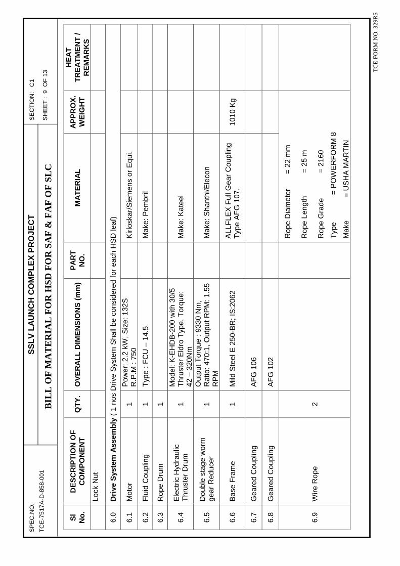
SP
EC
.NO
. S
SL
V L
AU
NC
H C
OM
PL
EX
PR
OJE
CT
S
EC
TIO
N:
C1
TC
E-7
517A
-D-8
58-0
01
BIL
L O
F M
AT
ER
IAL
FO
R H
SD F
OR
SA
F &
FA
F O
F S
LC
S
HE
ET
: 9
OF
13
T
CE
FO
RM
NO
. 329
R5
Sl
No
. D
ES
CR
IPT
ION
OF
C
OM
PO
NE
NT
Q
TY
. O
VE
RA
LL
DIM
EN
SIO
NS
(m
m)
PA
RT
N
O.
MA
TE
RIA
L
AP
PR
OX
. W
EIG
HT
HE
AT
T
RE
AT
ME
NT
/ R
EM
AR
KS
Lo
ck N
ut
6.0
Dri
ve S
yste
m A
ssem
bly
( 1
nos
Driv
e S
yste
m S
hall
be c
onsi
dere
d fo
r ea
ch H
SD
leaf
)
6.1
Mot
or
1 P
ower
: 2.2
kW
, Siz
e: 1
32S
R
.P.M
: 75
0
Kirl
oska
r/S
iem
ens
or E
qui.
6.2
Flu
id C
oupl
ing
1 T
ype
: FC
U –
14.
5
Mak
e: P
embr
il
6.3
Rop
e D
rum
1
6.4
Ele
ctric
Hyd
raul
ic
Thr
uste
r D
rum
1
Mod
el: K
-EH
DB
-200
with
30/
5 T
hrus
ter
Eld
ro T
ype,
Tor
que:
42
– 3
20N
m
M
ake:
Kat
eel
6.5
Dou
ble
stag
e w
orm
ge
ar R
educ
er
1 O
utpu
t Tor
que
: 933
0 N
m,
Rat
io: 4
70:1
, Out
put R
PM
: 1.5
5 R
PM
Mak
e: S
hant
hi/E
leco
n
6.6
Bas
e F
ram
e 1
Mild
Ste
el E
250
-BR
; IS
:206
2
ALL
FLE
X F
ull G
ear
Cou
plin
g T
ype
AF
G 1
07.
1010
Kg
6.7
Gea
red
Cou
plin
g
AF
G 1
06
6.8
Gea
red
Cou
plin
g
AF
G 1
02
6.9
Wire
Rop
e 2
Rop
e D
iam
eter
= 2
2 m
m
Rop
e Le
ngth
=
25
m
Rop
e G
rade
= 2
160
Typ
e
=
PO
WE
RF
OR
M 8
Mak
e
= U
SH
A M
AR
TIN
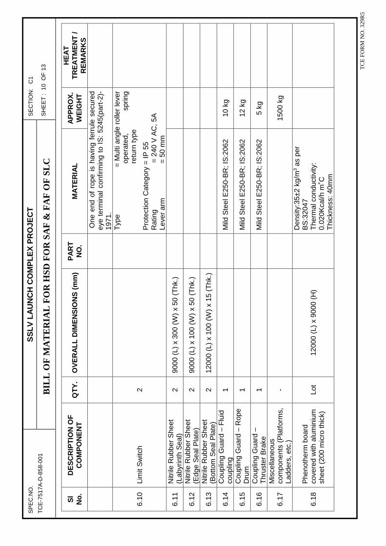
SP
EC
.NO
. S
SL
V L
AU
NC
H C
OM
PL
EX
PR
OJE
CT
S
EC
TIO
N:
C1
TC
E-7
517A
-D-8
58-0
01
BIL
L O
F M
AT
ER
IAL
FO
R H
SD F
OR
SA
F &
FA
F O
F S
LC
S
HE
ET
: 1
0 O
F 1
3
T
CE
FO
RM
NO
. 329
R5
Sl
No
. D
ES
CR
IPT
ION
OF
C
OM
PO
NE
NT
Q
TY
. O
VE
RA
LL
DIM
EN
SIO
NS
(m
m)
PA
RT
N
O.
MA
TE
RIA
L
AP
PR
OX
. W
EIG
HT
HE
AT
T
RE
AT
ME
NT
/ R
EM
AR
KS
O
ne e
nd o
f ro
pe i
s ha
ving
fer
rule
sec
ured
ey
e te
rmin
al c
onfir
min
g to
IS
: 52
45(p
art-
2)-
1971
.
6.10
Li
mit
Sw
itch
2
Typ
e
=
Mul
ti an
gle
rolle
r le
ver
oper
ated
, sp
ring
retu
rn ty
pe
Pro
tect
ion
Cat
egor
y =
IP 5
5 R
atin
g
= 2
40 V
AC
, 5A
Le
ver
arm
=
50
mm
6.11
N
itrile
Rub
ber
She
et
(Lab
yrin
th S
eal)
2 90
00 (
L) x
300
(W
) x
50 (
Thk
.)
6.12
N
itrile
Rub
ber
She
et
(Edg
e S
eal P
late
) 2
9000
(L)
x 1
00 (
W)
x 50
(T
hk.)
6.13
N
itrile
Rub
ber
She
et
(Bot
tom
Sea
l Pla
te)
2 12
000
(L)
x 10
0 (W
) x
15 (
Thk
.)
6.14
C
oupl
ing
Gua
rd –
Flu
id
coup
ling
1
M
ild S
teel
E25
0-B
R; I
S:2
062
10 k
g
6.15
C
oupl
ing
Gua
rd –
Rop
e D
rum
1
Mild
Ste
el E
250-
BR
; IS
:206
2 12
kg
6.16
C
oupl
ing
Gua
rd –
T
hrus
ter
Bra
ke
1
M
ild S
teel
E25
0-B
R; I
S:2
062
5 kg
6.17
M
isce
llane
ous
com
pone
nts
(Pla
tform
s,
Ladd
ers,
etc
.)
-
1500
kg
6.18
P
heno
ther
m b
oard
co
vere
d w
ith a
lum
iniu
m
shee
t (20
0 m
icro
thic
k)
Lot
1200
0 (L
) x
9000
(H
)
Den
sity
:35±
2 kg
/m3
as p
er
BS
:320
47
The
rmal
con
duct
ivity
: 0.
020K
cal/h
m˚C
T
hick
ness
: 40m
m

SP
EC
.NO
. S
SL
V L
AU
NC
H C
OM
PL
EX
PR
OJE
CT
S
EC
TIO
N:
C1
TC
E-7
517A
-D-8
58-0
01
BIL
L O
F M
AT
ER
IAL
FO
R H
SD F
OR
SA
F &
FA
F O
F S
LC
S
HE
ET
: 1
1 O
F 1
3
T
CE
FO
RM
NO
. 329
R5
Sl
No
. D
ES
CR
IPT
ION
OF
C
OM
PO
NE
NT
Q
TY
. O
VE
RA
LL
DIM
EN
SIO
NS
(m
m)
PA
RT
N
O.
MA
TE
RIA
L
AP
PR
OX
. W
EIG
HT
HE
AT
T
RE
AT
ME
NT
/ R
EM
AR
KS
6.19
T
hrou
gh B
olts
/ F
ound
atio
n bo
lts fo
r al
l D
oors
Lo
t
3000
kg
Item
no:
6.1
9 is
Thr
ough
bol
ts /
fou
ndat
ion
bolts
are
use
d fo
r fix
ing
brac
kets
(la
tera
l gui
de a
ssem
blie
s /
cycl
one
lock
ass
embl
ies
/ w
heel
mou
ntin
g br
acke
ts)
to t
he w
all.
4000
kgs
of
bolts
are
exp
ecte
d fo
r al
l 6
num
ber
of d
oor
leav
es.
Hen
ce t
hrou
gh a
re n
ot m
entio
ned
in o
ther
doo
r B
OQ
’s.

SP
EC
.NO
. S
SL
V L
AU
NC
H C
OM
PL
EX
PR
OJE
CT
S
EC
TIO
N:
C1
SLC
-DO
OR
-201
9-00
1 B
ILL
OF
MA
TE
RIA
L F
OR
SD
S
HE
ET
: 1
OF
13
T
CE
FO
RM
NO
. 329
R5
BIL
L O
F M
AT
ER
IAL
S
DE
TA
ILS
OF
FA
BR
ICA
TE
D C
OM
PO
NE
NT
S
Mat
eria
l Qua
ntiti
es m
entio
ned
in th
e fo
llow
ing
Tab
le is
for
1 no
. of D
oor
leaf
onl
y. E
ach
SD
com
pris
es 2
leav
es, d
rive
arra
ngem
ent a
nd o
ther
as
sem
blie
s. S
AF
hav
e 7
nos
SD
s an
d F
AF
hav
e 3
no S
D.
Hen
ce, q
uan
titi
es o
f 20
leav
es s
hal
l be
con
sid
ered
fo
r ca
lcu
lati
ng
To
tal M
ater
ial Q
uan
titi
es o
f S
Ds.
Sl N
o.
DE
SC
RIP
TIO
N O
F
CO
MP
ON
EN
T
QT
Y.
OV
ER
AL
L D
IME
NS
ION
S
(mm
) P
AR
T
NO
. M
AT
ER
IAL
A
PP
RO
X.
WE
IGH
T
HE
AT
T
RE
AT
ME
NT
/ R
EM
AR
KS
1.0
D
oo
r S
tru
ctu
re a
nd
Dri
ve &
Idle
Hin
ge
Ass
emb
ly
1.1
IS
MB
400
6
ISM
B 4
00 x
149
0 Lg
.
IS:8
08
551
kg
1.2
IS
MB
400
5
ISM
B 4
00 x
202
0 Lg
.
IS:8
08
622
kg
1.3
P
late
8
150
x 12
50 x
10
(Thk
.)
M
ild S
teel
E 2
50-B
R;
IS:2
062
118
kg
1.4
P
late
16
15
0 x
1320
x 1
0 (T
hk.)
Mild
Ste
el E
250
-BR
; IS
:206
2 24
9 kg
1.5
P
late
2
400
x 19
000
x 10
(T
hk.)
Mild
Ste
el E
250
-BR
; IS
:206
2 56
5 kg
1.6
P
late
4
150
x 20
00 x
10
(Thk
.)
M
ild S
teel
E 2
50-B
R;
IS:2
062
94 k
g
1.6A
P
late
2
400
x 20
00 x
10
(Thk
.)
M
ild S
teel
E 2
50-B
R;
IS:2
062
126
kg
1.7
IS
MC
100
24
IS
MB
100
x 1
810
Lg.
IS
:808
40
0 kg
1.8
F
ront
She
et
1 20
20 x
900
0 x
3.15
(T
hk.)
Mild
Ste
el E
250
-BR
; IS
:206
2 45
0 kg
1.9
R
ear
She
et
1 20
20 x
900
0 x
3.15
(T
hk.)
Mild
Ste
el E
250
-BR
; IS
:206
2 45
0 kg

SP
EC
.NO
. S
SL
V L
AU
NC
H C
OM
PL
EX
PR
OJE
CT
S
EC
TIO
N:
C1
SLC
-DO
OR
-201
9-00
1 B
ILL
OF
MA
TE
RIA
L F
OR
SD
S
HE
ET
: 2
OF
13
T
CE
FO
RM
NO
. 329
R5
Sl N
o.
DE
SC
RIP
TIO
N O
F
CO
MP
ON
EN
T
QT
Y.
OV
ER
AL
L D
IME
NS
ION
S
(mm
) P
AR
T
NO
. M
AT
ER
IAL
A
PP
RO
X.
WE
IGH
T
HE
AT
T
RE
AT
ME
NT
/ R
EM
AR
KS
1.9A
P
late
4
410
x 38
0 x
10 (
Thk
.)
M
ild S
teel
E 2
50-B
R;
IS:2
062
49 k
g
1.9B
P
late
2
380
x 48
0 x
10 (
Thk
.)
M
ild S
teel
E 2
50-B
R;
IS:2
062
29 k
g
1.10
Pla
te
8 80
x 4
00 x
30
(Thk
.)
M
ild S
teel
E 2
50-B
R;
IS:2
062
60 k
g
1.11
Pla
te
2 40
0 x
500
x 36
(T
hk.)
Mild
Ste
el E
250
-BR
; IS
:206
2 11
3 kg
1.11
A
Pla
te
2 40
0 x
500
x 20
(T
hk.)
Mild
Ste
el E
250
-BR
; IS
:206
2 63
kg
1.12
Pla
te
2 40
0 x
500
x 50
(T
hk.)
Mild
Ste
el E
250
-BR
; IS
:206
2 15
7 kg
1.13
Pla
te
2 40
0 x
600
x 63
(T
hk.)
Mild
Ste
el E
250
-BR
; IS
:206
2 23
7 kg
1.14
Stif
fene
r 2
220
x 22
5 x
50 (
Thk
.)
M
ild S
teel
E 2
50-B
R;
IS:2
062
39 k
g
1.14
A
Stif
fene
r 2
220
x 25
0 x
50 (
Thk
.)
M
ild S
teel
E 2
50-B
R;
IS:2
062
43 k
g
1.15
Bus
h
2 O
D 3
50 x
ID 1
90 x
150
Thi
ck
M
ild S
teel
E 2
50-B
R;
IS:2
062
160
kg
1.16
Sha
ft
1 Ø
230
x 8
95 L
g
En-
24T
29
2 kg
1.17
Pla
te
3 50
0 x
550
x 63
(T
hk.)
Mild
Ste
el E
250
-BR
; IS
:206
2 40
8 kg
1.18
Pla
te
3 50
0 x
550
x 50
(T
hk.)
Mild
Ste
el E
250
-BR
; IS
:206
2 32
4 kg
1.19
Stif
fene
r 6
500
x 55
0 x
30 (
Thk
.)
M
ild S
teel
E 2
50-B
R;
IS:2
062
389
kg
1.20
Pla
te
1 50
0 x
500
x 63
(T
hk.)
Mild
Ste
el E
250
-BR
; IS
:206
2 12
4 kg

SP
EC
.NO
. S
SL
V L
AU
NC
H C
OM
PL
EX
PR
OJE
CT
S
EC
TIO
N:
C1
SLC
-DO
OR
-201
9-00
1 B
ILL
OF
MA
TE
RIA
L F
OR
SD
S
HE
ET
: 3
OF
13
T
CE
FO
RM
NO
. 329
R5
Sl N
o.
DE
SC
RIP
TIO
N O
F
CO
MP
ON
EN
T
QT
Y.
OV
ER
AL
L D
IME
NS
ION
S
(mm
) P
AR
T
NO
. M
AT
ER
IAL
A
PP
RO
X.
WE
IGH
T
HE
AT
T
RE
AT
ME
NT
/ R
EM
AR
KS
1.21
Pla
te
1 68
0 x
550
x 50
(T
hk.)
Mild
Ste
el E
250
-BR
; IS
:206
2 13
3 kg
1.22
Stif
fene
r 2
135
x 15
0 x
30 (
Thk
.)
M
ild S
teel
E 2
50-B
R;
IS:2
062
10 k
g
1.23
Tap
er R
olle
r B
earin
g
4 32
030-
X
S
KF
1.24
Lock
Nut
4
KM
29
S
KF
1.25
Lock
Was
her
4 M
B 2
9
IS:8
08
1.26
Sha
ft
1 Ø
230
x 6
75 L
g
En-
24T
22
0 kg
1.27
Bus
h
4 O
D 2
85 x
ID 2
00 x
80
Thi
ck
M
ild S
teel
E 2
50-B
R;
IS:2
062
81 k
g
1.28
Key
for
Act
uato
r sh
aft
1 36
x 2
0 x
165
Lg
M
ild S
teel
E 2
50-B
R;
IS:2
062
1 kg
1.29
Key
for
Bra
cket
r sh
aft
2 45
x 2
5 x
130
Lg
M
ild S
teel
E 2
50-B
R;
IS:2
062
2 kg
1.30
Lock
ing
Pla
te
4 O
D 2
85 x
ID 1
85 x
36
Thi
ck
M
ild S
teel
E 2
50-B
R;
IS:2
062
42 k
g
1.31
Hex
agon
al S
crew
24
M
8 x
30
Lg, C
lass
8.8
IS:1
367
1.32
Spa
cer
Pla
te
1 50
0 x
380
x 14
(T
hk.)
IS:1
367
21 k
g
2.0
Sw
ing
Dri
ve S
yste
m
2.1
Pla
te
2 12
0 x
9000
x 3
.15
(Thk
.)
M
ild S
teel
E 2
50-B
R;
IS:2
062
27 k
g
2.2
Hex
Bol
ts w
ith N
ut, W
ashe
r &
Spr
ing
Was
her
2 M
30 x
150
Lg
IS
:136
7
2.3
Hex
agon
al B
olt
2 M
30
IS
:136
7

SP
EC
.NO
. S
SL
V L
AU
NC
H C
OM
PL
EX
PR
OJE
CT
S
EC
TIO
N:
C1
SLC
-DO
OR
-201
9-00
1 B
ILL
OF
MA
TE
RIA
L F
OR
SD
S
HE
ET
: 4
OF
13
T
CE
FO
RM
NO
. 329
R5
Sl N
o.
DE
SC
RIP
TIO
N O
F
CO
MP
ON
EN
T
QT
Y.
OV
ER
AL
L D
IME
NS
ION
S
(mm
) P
AR
T
NO
. M
AT
ER
IAL
A
PP
RO
X.
WE
IGH
T
HE
AT
T
RE
AT
ME
NT
/ R
EM
AR
KS
2.4
Tap
per
Rol
ler
Bea
ring
-
4 32
030
x
SK
F
2.5
Hyd
raul
ic R
otar
y A
ctua
tor
1
Dou
ble
Rac
k &
Foo
t Mou
ntin
g T
ype
Out
Put
Tor
que:
35
KN
m,
Ope
ratin
g P
ress
ure:
207
bar
, H
ollo
w S
haft
Siz
e : 1
40 m
m
2.6
Fla
me
Pro
of H
ydra
ulic
P
ower
Pac
and
Loc
al
Con
trol
for
Indi
vidu
al
Hyd
raul
ic R
otar
y A
ctua
tor
1
2.7
Lim
it S
witc
h
2
Typ
e
= M
ulti
angl
e ro
ller
leve
r op
erat
ed,
sprin
g re
turn
type
Pro
tect
ion
Cat
egor
y =
IP 5
5 R
atin
g
= 2
40 V
AC
, 5A
Le
ver
arm
=
50
mm
Li
mit
Sw
itch
2.8
Nitr
ile R
ubbe
r S
heet
(L
abyr
inth
Sea
l),
2 90
00 (
L) x
300
(W
) x
50 (
Thk
.)
2.9
Nitr
ile R
ubbe
r S
heet
(E
dge
Sea
l Pla
te),
2
9000
(L)
x 1
00 (
W)
x 50
(T
hk.)
2.10
N
itrile
Rub
ber
She
et
(Bot
tom
Sea
l Pla
te),
2
2000
(L)
x 1
00 (
W)
x 15
(T
hk.)
2.11
P
heno
ther
m b
oard
cov
ered
w
ith a
lum
iniu
m s
heet
(20
0 m
icro
thic
k),
1 Lo
t S
ize:
200
0 (L
) x
9000
(H
)
Den
sity
:35±
2 kg
/m3
as p
er
BS
:320
47
The
rmal
con
duct
ivity
: 0.
020K
cal/h
m˚C
T
hick
ness
: 40m
m

SP
EC
.NO
. S
SL
V L
AU
NC
H C
OM
PL
EX
PR
OJE
CT
S
EC
TIO
N:
C1
SLC
-DO
OR
-201
9-00
1 B
ILL
OF
MA
TE
RIA
L F
OR
SD
S
HE
ET
: 5
OF
13
T
CE
FO
RM
NO
. 329
R5
Sl N
o.
DE
SC
RIP
TIO
N O
F
CO
MP
ON
EN
T
QT
Y.
OV
ER
AL
L D
IME
NS
ION
S
(mm
) P
AR
T
NO
. M
AT
ER
IAL
A
PP
RO
X.
WE
IGH
T
HE
AT
T
RE
AT
ME
NT
/ R
EM
AR
KS
2.12
T
hrou
gh B
olts
/ F
ound
atio
n bo
lts fo
r al
l Doo
rs
Lot
40
00 k
g
3.0
Cyc
lon
e L
ock
Ass
emb
ly (
2 n
os C
yclo
ne lo
ck S
hall
be c
onsi
dere
d fo
r ea
ch S
win
g D
oor
leaf
)
3.1
Pla
te
5 50
0 x
500
x 16
(T
hk.)
Mild
Ste
el E
250
-BR
; IS
:206
2 15
7 kg
3.2
Pla
te
1 70
0 x
500
x 32
(T
hk.)
Mild
Ste
el E
250
-BR
; IS
:206
2 10
7 kg
3.3
Stif
fene
r 1
350
x 25
0 x
32 (
Thk
.)
M
ild S
teel
E 2
50-B
R;
IS:2
062
22 k
g
3.4
Pla
te
1 50
0 x
300
x 40
(T
hk.)
Mild
Ste
el E
250
-BR
; IS
:206
2 47
kg
3.5
Pla
te
2 50
0 x
300
x 40
(T
hk.)
Mild
Ste
el E
250
-BR
; IS
:206
2 94
kg
3.5A
B
ush
for
Bra
cket
2
OD
220
x ID
155
x 5
6 T
hick
Mild
Ste
el E
250
-BR
; IS
:206
2 17
kg
3.6
Stif
fene
r 4
350
x 25
0 x
32 (
Thk
.)
M
ild S
teel
E 2
50-B
R;
IS:2
062
88 k
g
3.7
Pla
te
2 50
0 x
375
x 36
(T
hk.)
Mild
Ste
el E
250
-BR
; IS
:206
2 10
6 kg
3.7A
B
ush
for
Bra
cket
2
OD
235
x ID
170
x 5
2 T
hick
Mild
Ste
el E
250
-BR
; IS
:206
2 17
kg
3.8
Stif
fene
r 3
350
x 25
0 x
32 (
Thk
.)
M
ild S
teel
E 2
50-B
R;
IS:2
062
8 kg
3.9
Circ
ular
Pla
te
1 O
D 2
65 x
ID 3
4 x
12 T
hick
Mild
Ste
el E
250
-BR
; IS
:206
2 5
kg
3.10
C
ircul
ar P
late
1
OD
265
x ID
165
.1 x
12
Thi
ck
M
ild S
teel
E 2
50-B
R;
IS:2
062
3 kg
3.11
C
ircul
ar P
late
1
OD
265
x ID
39
x 12
Thi
ck
M
ild S
teel
E 2
50-B
R;
IS:2
062
5 kg

SP
EC
.NO
. S
SL
V L
AU
NC
H C
OM
PL
EX
PR
OJE
CT
S
EC
TIO
N:
C1
SLC
-DO
OR
-201
9-00
1 B
ILL
OF
MA
TE
RIA
L F
OR
SD
S
HE
ET
: 6
OF
13
T
CE
FO
RM
NO
. 329
R5
Sl N
o.
DE
SC
RIP
TIO
N O
F
CO
MP
ON
EN
T
QT
Y.
OV
ER
AL
L D
IME
NS
ION
S
(mm
) P
AR
T
NO
. M
AT
ER
IAL
A
PP
RO
X.
WE
IGH
T
HE
AT
T
RE
AT
ME
NT
/ R
EM
AR
KS
3.12
15
0 N
B S
teel
Tub
e 1
OD
165
.1 x
4.5
Thi
ck x
105
8 Lg
IS :
1161
3.13
P
late
1
75 x
75
x 35
(T
hk.)
Mild
Ste
el E
250
-BR
; IS
:206
2 19
kg
3.14
P
in
1 Ø
16
x 12
5 Lg
Mild
Ste
el E
250
-BR
; IS
:206
2 2
kg
3.15
Lo
ckin
g P
in
1 Ø
20
x 20
0 Lg
Mild
Ste
el E
250
-BR
; IS
:206
2 0.
2 kg
3.16
P
in
1 O
D 1
50 x
ID 3
5 x
1425
Lg
E
n-24
T
0.5
kg
3.17
S
crew
Rod
1
Ø 4
5 x
1200
Lg
E
n-24
T
187
kg
3.18
Lo
ckin
g P
late
1
20 x
20
x 8
thic
k
Mild
Ste
el E
250
-BR
; IS
:206
2 15
kg
3.19
H
and
Whe
el
1 N
omin
al D
ia 2
50
IS
: 304
8 (C
.I)
0.03
kg
3.20
H
ex S
crew
with
was
her
6 M
12 x
35
Lg
IS
: 13
67, C
lass
8.8
3.21
H
ex S
crew
with
Nut
&
Was
her
6 M
12 x
50
Lg
IS
: 13
67, C
lass
8.8
3.22
C
SK
Scr
ew
4 M
8 x
50 L
g
IS :
1367
, Cla
ss 8
.8
3.23
H
ex S
crew
with
Was
her
1 M
8 x
20 L
g
IS :
1367
, Cla
ss 8
.8
3.24
C
hain
1
300
Lg
M
ild S
teel
E 2
50-B
R;
IS:2
062
3.25
H
ex S
crew
with
Nut
&
Was
her
4 M
30 x
135
Lg
IS
: 13
67, C
lass
8.8
Item
no:
2.1
2 is
Thr
ough
bol
ts /
fou
ndat
ion
bolts
are
use
d fo
r fix
ing
brac
kets
(H
inge
Bra
cket
ass
embl
ies
/ cy
clon
e lo
ck a
ssem
blie
s) t
o th
e w
all.
4000
kgs
of b
olts
are
exp
ecte
d fo
r al
l 20
num
ber
of d
oor
leav
es. H
ence
thro
ugh
are
not m
entio
ned
in o
ther
doo
r B
OQ
’s.
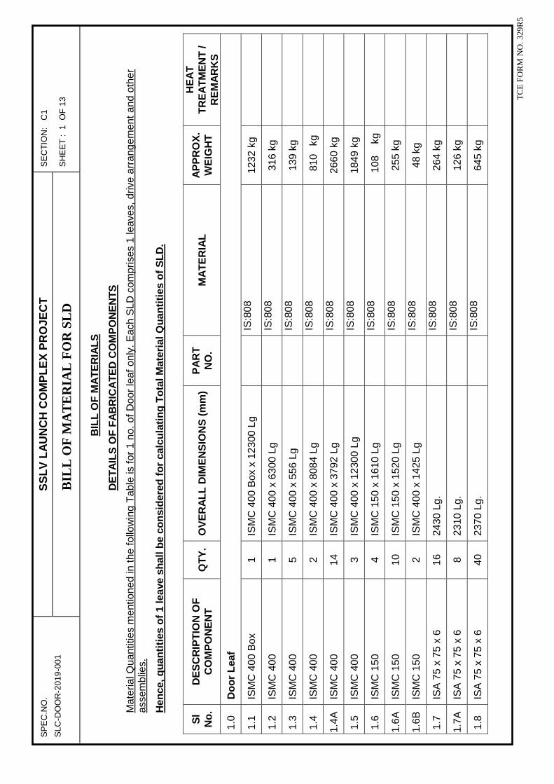
SP
EC
.NO
. S
SL
V L
AU
NC
H C
OM
PL
EX
PR
OJE
CT
S
EC
TIO
N:
C1
SLC
-DO
OR
-201
9-00
1 B
ILL
OF
MA
TE
RIA
L F
OR
SL
D
SH
EE
T :
1 O
F 1
3
T
CE
FO
RM
NO
. 329
R5
BIL
L O
F M
AT
ER
IAL
S
DE
TA
ILS
OF
FA
BR
ICA
TE
D C
OM
PO
NE
NT
S
Mat
eria
l Qua
ntiti
es m
entio
ned
in th
e fo
llow
ing
Tab
le is
for
1 no
. of D
oor
leaf
onl
y. E
ach
SLD
com
pris
es 1
leav
es, d
rive
arra
ngem
ent a
nd o
ther
as
sem
blie
s.
Hen
ce, q
uan
titi
es o
f 1
leav
e sh
all b
e co
nsi
der
ed f
or
calc
ula
tin
g T
ota
l Mat
eria
l Qu
anti
ties
of
SL
D.
Sl
No
. D
ES
CR
IPT
ION
OF
C
OM
PO
NE
NT
Q
TY
. O
VE
RA
LL
DIM
EN
SIO
NS
(m
m)
PA
RT
N
O.
MA
TE
RIA
L
AP
PR
OX
. W
EIG
HT
HE
AT
T
RE
AT
ME
NT
/ R
EM
AR
KS
1.0
Do
or
Lea
f
1.1
ISM
C 4
00 B
ox
1 IS
MC
400
Box
x 1
2300
Lg
IS
:808
12
32 k
g
1.2
ISM
C 4
00
1 IS
MC
400
x 6
300
Lg
IS
:808
31
6 kg
1.3
ISM
C 4
00
5 IS
MC
400
x 5
56 L
g
IS:8
08
139
kg
1.4
ISM
C 4
00
2 IS
MC
400
x 8
084
Lg
IS
:808
81
0 kg
1.4A
IS
MC
400
14
IS
MC
400
x 3
792
Lg
IS
:808
26
60 k
g
1.5
ISM
C 4
00
3 IS
MC
400
x 1
2300
Lg
IS
:808
18
49 k
g
1.6
ISM
C 1
50
4 IS
MC
150
x 1
610
Lg
IS
:808
10
8 kg
1.6A
IS
MC
150
10
IS
MC
150
x 1
520
Lg
IS
:808
25
5 kg
1.6B
IS
MC
150
2
ISM
C 4
00 x
142
5 Lg
IS:8
08
48 k
g
1.7
ISA
75
x 75
x 6
16
24
30 L
g.
IS
:808
26
4 kg
1.7A
IS
A 7
5 x
75 x
6
8 23
10 L
g.
IS
:808
12
6 kg
1.8
ISA
75
x 75
x 6
40
23
70 L
g.
IS
:808
64
5 kg

SP
EC
.NO
. S
SL
V L
AU
NC
H C
OM
PL
EX
PR
OJE
CT
S
EC
TIO
N:
C1
SLC
-DO
OR
-201
9-00
1 B
ILL
OF
MA
TE
RIA
L F
OR
SL
D
SH
EE
T :
2 O
F 1
3
T
CE
FO
RM
NO
. 329
R5
Sl
No
. D
ES
CR
IPT
ION
OF
C
OM
PO
NE
NT
Q
TY
. O
VE
RA
LL
DIM
EN
SIO
NS
(m
m)
PA
RT
N
O.
MA
TE
RIA
L
AP
PR
OX
. W
EIG
HT
HE
AT
T
RE
AT
ME
NT
/ R
EM
AR
KS
1.9
Lad
der
Ste
p 35
IS
R 0
16 x
600
Lg
IS
:206
2, F
e 41
0 -
B
34 k
g
1.10
IS
MC
250
Box
2
ISM
C 2
50 B
ox x
291
Lg
IS
:808
36
kg
1.11
B
ase
Pla
te
4 45
0 x
380
x 25
thic
k
Mild
Ste
el E
250
-BR
; IS
:206
2 13
4 kg
1.12
B
ase
Pla
te
1
450
x 45
0 x
16 th
ick
M
ild S
teel
E 2
50-B
R; I
S:2
062
25
kg
1.13
S
tiffe
ner
4
316
x 17
5 x
10 th
ick
M
ild S
teel
E 2
50-B
R; I
S:2
062
17 k
g
1.14
S
tiffe
ner
4 31
6 x
120
x 10
thic
k
Mild
Ste
el E
250
-BR
; IS
:206
2 12
kg
1.15
S
tiffe
ner
4
125
x 10
0 x
10 th
ick
M
ild S
teel
E 2
50-B
R; I
S:2
062
4 kg
1.16
IS
MC
250
Box
3
ISM
C 2
50 B
ox x
50
Lg
IS
:808
9
kg
1.17
B
ase
Pla
te
3 39
0 x
300
x 20
thic
k
Mild
Ste
el E
250
-BR
; IS
:206
2 55
kg
1.18
S
tiffe
ner
2
350
x 20
0 x
16 th
ick
M
ild S
teel
E 2
50-B
R; I
S:2
062
18 k
g
1.19
P
ipe
2 O
D 1
39.7
, Wal
l Thi
ck 2
0 x
400
Lg
D
IN 2
448
47 k
g
1.20
P
late
2
25
0 x
220
x 20
thic
k
Mild
Ste
el E
250
-BR
; IS
:206
2 17
kg
1.21
P
late
1
25
0 x
120
x 20
thic
k
Mild
Ste
el E
250
-BR
; IS
:206
2 5
kg
1.22
P
late
1
1230
0 x
8940
x 2
thic
k
Mild
Ste
el E
250
-BR
; IS
:206
2 17
26 k
g
1.23
P
late
1
1230
0 x
8940
x 3
.15
thic
k
Mild
Ste
el E
250
-BR
; IS
:206
2 27
19 k
g
2.0
D
rive
& Id
le W
hee
l Ass
emb
ly (
1 n
o D
rive
& Id
le W
heel
Ass
embl
y S
hall
be c
onsi
dere
d fo
r ea
ch S
LD le
af)
2.1
P
late
4
450
x 43
5 x
25 th
ick
M
ild S
teel
E 2
50-B
R; I
S:2
062
154
kg

SP
EC
.NO
. S
SL
V L
AU
NC
H C
OM
PL
EX
PR
OJE
CT
S
EC
TIO
N:
C1
SLC
-DO
OR
-201
9-00
1 B
ILL
OF
MA
TE
RIA
L F
OR
SL
D
SH
EE
T :
3 O
F 1
3
T
CE
FO
RM
NO
. 329
R5
Sl
No
. D
ES
CR
IPT
ION
OF
C
OM
PO
NE
NT
Q
TY
. O
VE
RA
LL
DIM
EN
SIO
NS
(m
m)
PA
RT
N
O.
MA
TE
RIA
L
AP
PR
OX
. W
EIG
HT
HE
AT
T
RE
AT
ME
NT
/ R
EM
AR
KS
2.2
P
late
4
450
x 13
5 x
25 th
ick
M
ild S
teel
E 2
50-B
R; I
S:2
062
48 k
g
2.3
S
tiffe
ner
4 38
5 x
90 x
10
thic
k
Mild
Ste
el E
250
-BR
; IS
:206
2 11
kg
2.4
S
tiffe
ner
12
150
x 90
x 1
0 th
ick
M
ild S
teel
E 2
50-B
R; I
S:2
062
13 k
g
2.5
W
heel
2
Ø 5
00 x
120
Thi
ck
C
55M
n75
310
kg
2.6
Id
le S
haft
1 Ø
125
x 2
95 L
g
En-
24T
18
kg
2.7
D
rive
Sha
ft
1 Ø
125
x 4
40 L
g
En-
24T
24
kg
2.8
K
ey
2 28
x 1
6 x
100
Lg
45
C8
2.9
Lo
ckin
g P
late
2
60 x
60
x 10
Thi
ck
M
ild S
teel
E 2
50-B
R; I
S:2
062
1 kg
2.1
0 S
lotte
d C
KS
Hd.
Scr
ew
2
IS
: 136
7
2.1
1 B
earin
g B
ush
4 O
D 2
20 x
ID 1
50 x
75
thic
k
Mild
Ste
el E
250
-BR
; IS
:206
2 37
kg
2.1
2 S
pher
ical
Rol
ler
Bea
ring
4 B
ore:
Ø 9
0 x
OD
: Ø 1
60 x
40
Thi
ck
F
AG
/ S
KF
2.1
3 Lo
ck N
ut &
Tab
Was
her
4
KM
17
& M
B17
FA
G /
SK
F
2.1
4 B
earin
g C
over
3
OD
220
x ID
85
x 40
Thi
ck
M
ild S
teel
E 2
50-B
R; I
S:2
062
13 k
g
2.1
5 B
earin
g C
over
1
OD
220
x 4
0 T
hick
Mild
Ste
el E
250
-BR
; IS
:206
2 5
kg
2.1
6 H
ex S
crew
with
Was
her
24
M
12 x
35
Lg
IS
: 13
67, 8
.8 C
lass
G
uid
e W
hee
l Ass
emb
ly (
6 n
os G
uide
Whe
el A
ssem
bly
Sha
ll be
con
side
red
for
each
SLD
leaf
)
2.1
7 B
ase
plat
e 6
390
x 30
0 x
36 th
ick
Mild
Ste
el E
250
-BR
; IS
:206
2 19
8 kg

SP
EC
.NO
. S
SL
V L
AU
NC
H C
OM
PL
EX
PR
OJE
CT
S
EC
TIO
N:
C1
SLC
-DO
OR
-201
9-00
1 B
ILL
OF
MA
TE
RIA
L F
OR
SL
D
SH
EE
T :
4 O
F 1
3
T
CE
FO
RM
NO
. 329
R5
Sl
No
. D
ES
CR
IPT
ION
OF
C
OM
PO
NE
NT
Q
TY
. O
VE
RA
LL
DIM
EN
SIO
NS
(m
m)
PA
RT
N
O.
MA
TE
RIA
L
AP
PR
OX
. W
EIG
HT
HE
AT
T
RE
AT
ME
NT
/ R
EM
AR
KS
2.1
8 A
xle
6 Ø
150
x 2
56 L
g
Mild
Ste
el E
250
-BR
; IS
:206
2 15
8 kg
2.1
9 G
uide
Whe
el
6 Ø
350
x 1
08 L
g.
C
55M
n75
308
kg
2.2
0 D
eep
groo
ve B
all
bear
ing
12
B
ore:
Ø 1
20 x
OD
: Ø 2
15 x
40
Thi
ck
F
AG
/ SK
F
2.2
1 E
nd C
over
A
6
M
ild S
teel
E 2
50-B
R; I
S:2
062
17 k
g
2.2
2 E
nd C
over
B
6
M
ild S
teel
E 2
50-B
R; I
S:2
062
34 k
g
2.2
3 S
tiffe
ner
48
12
0 x
70 x
10
thic
k
Mild
Ste
el E
250
-BR
; IS
:206
2 32
kg
2.2
4 Lo
ck N
ut &
Tab
Was
her
6 K
M 2
3 &
MB
23
F
AG
/ SK
F
2.2
5 H
ex h
ead
Bol
t 36
M
10
x 2
2 Lg
IS:2
269,
8.8
Cla
ss
5
Fla
me
Pro
of G
eare
d M
otor
2
Pow
er: 0
.75
KW
In
put S
peed
: 100
0 R
PM
O
utpu
t Spe
ed: 2
.11
RP
M
Out
put T
orqu
e: 3
222
Nm
R
educ
tion
Rat
io: 4
35
M
ake:
PB
L or
Equ
ival
ent
6
Cou
plin
g 2
Ø 2
50
7
Pla
te
2 40
0 x
400
x 16
thic
k
Mild
Ste
el E
250
-BR
; IS
:206
2 40
kg
8
SQ
. Hol
low
Sec
tion
2 22
0 x
220
x 8
thic
k x
398
Lg
IS
: 492
3 Y
ST
310
Gr
41 k
g
9
Rec
tang
ular
Hol
low
S
ectio
n 2
200
x 10
0 x
8 th
ick
x 10
02 L
g
IS: 4
923
YS
T 3
10 G
r 69
kg
10
Pla
te
2 40
0 x
325
x 32
thic
k
M
ild S
teel
E 2
50-B
R; I
S:2
062
65 k
g

SP
EC
.NO
. S
SL
V L
AU
NC
H C
OM
PL
EX
PR
OJE
CT
S
EC
TIO
N:
C1
SLC
-DO
OR
-201
9-00
1 B
ILL
OF
MA
TE
RIA
L F
OR
SL
D
SH
EE
T :
5 O
F 1
3
T
CE
FO
RM
NO
. 329
R5
Sl
No
. D
ES
CR
IPT
ION
OF
C
OM
PO
NE
NT
Q
TY
. O
VE
RA
LL
DIM
EN
SIO
NS
(m
m)
PA
RT
N
O.
MA
TE
RIA
L
AP
PR
OX
. W
EIG
HT
HE
AT
T
RE
AT
ME
NT
/ R
EM
AR
KS
11
S
tiffe
ner
8 12
5 x
90 x
10
thic
k
Mild
Ste
el E
250
-BR
; IS
:206
2 7
kg
12
Stif
fene
r 4
298
x 18
0 x
10 th
ick
M
ild S
teel
E 2
50-B
R; I
S:2
062
17 k
g
13
Stif
fene
r 8
125
x 11
2 x
10 th
ick
M
ild S
teel
E 2
50-B
R; I
S:2
062
9 kg
14
Pla
te
2 19
0 x
90 x
6 th
ick
M
ild S
teel
E 2
50-B
R; I
S:2
062
2 kg
15
Sq.
Rai
l 1
60 x
60
x 22
000
Lg
C
55M
n75
623
kg
16
Sto
pper
Pla
te
2 40
0 x
200
x 32
thic
k
Mild
Ste
el E
250
-BR
; IS
:206
2 40
kg
17
Rub
ber
Pad
2
210
x320
x 1
0 th
ick
N
eopr
ene
18
ISM
C 2
00
2 IS
MC
200
x 2
4950
Lg
IS
: 80
8 11
13 k
g
19
Pla
te
144
184
x 68
x 1
0 th
ick
M
ild S
teel
E 2
50-B
R; I
S:2
062
141
kg
20
ISM
C 2
00
48
ISM
C 2
00 x
700
Lg
IS
: 80
8 74
9 kg
21
Key
20 x
12
x 11
0 Lg
45C
8
22
Key
22 x
14
x 11
0 Lg
45C
8
23
Hex
a. B
olt w
ith D
oubl
e W
ashe
r 28
M
24 x
100
Lg
IS
: 136
7, C
lass
8.8
24
Hex
a. B
olt w
ith D
oubl
e W
ashe
r 16
M
16 x
80
Lg
IS
: 136
7, C
lass
8.8
25
Hex
a. B
olt w
ith D
oubl
e W
ashe
r 8
M20
x 8
0 Lg
IS: 1
367,
Cla
ss 8
.8
26
Lim
it S
witc
h
2
T
ype
= M
ulti
angl
e ro
ller
leve
r op
erat
ed,
sprin
g re
turn
type

SP
EC
.NO
. S
SL
V L
AU
NC
H C
OM
PL
EX
PR
OJE
CT
S
EC
TIO
N:
C1
SLC
-DO
OR
-201
9-00
1 B
ILL
OF
MA
TE
RIA
L F
OR
SL
D
SH
EE
T :
6 O
F 1
3
T
CE
FO
RM
NO
. 329
R5
Sl
No
. D
ES
CR
IPT
ION
OF
C
OM
PO
NE
NT
Q
TY
. O
VE
RA
LL
DIM
EN
SIO
NS
(m
m)
PA
RT
N
O.
MA
TE
RIA
L
AP
PR
OX
. W
EIG
HT
HE
AT
T
RE
AT
ME
NT
/ R
EM
AR
KS
P
rote
ctio
n C
ateg
ory
= IP
55
Rat
ing
=
240
V A
C, 5
A
Leve
r ar
m
= 5
0 m
m
27
Thr
ough
Bol
ts /
Fou
ndat
ion
bolts
for
all
Doo
rs
Lot
10
0 kg
Item
no:
27
is T
hrou
gh b
olts
/ f
ound
atio
n bo
lts a
re u
sed
for
fixin
g br
acke
ts (
late
ral g
uide
ass
embl
ies)
to
the
wal
l. 10
0 kg
s of
bol
ts a
re e
xpec
ted
for
all 1
num
ber
of d
oor
leaf
. Hen
ce th
roug
h ar
e no
t men
tione
d in
oth
er d
oor
BO
Q’s
.
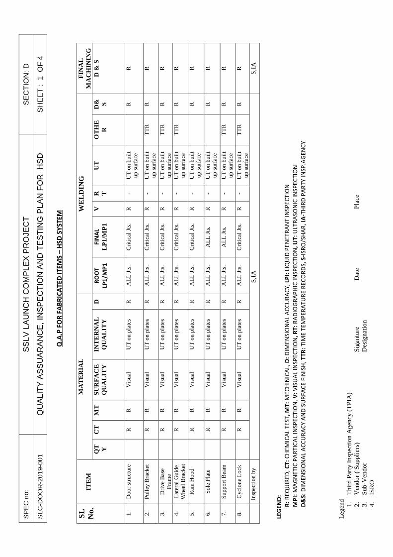
SP
EC
no:
S
SLV
LA
UN
CH
CO
MP
LEX
PR
OJE
CT
S
EC
TIO
N: D
SLC
-DO
OR
-201
9-00
1 Q
UA
LIT
Y A
SS
UA
RA
NC
E, I
NS
PE
CT
ION
AN
D T
ES
TIN
G P
LAN
FO
R H
SD
S
HE
ET
: 1
OF
4
Leg
end
1.
Thi
rd P
arty
Ins
pect
ion
Age
ncy
(TPI
A)
2.
Ven
dor
( Su
pplie
rs)
Si
gant
ure
D
ate
Pla
ce
3.
Sub-
Ven
dor
Des
igna
tion
4.
ISR
O
Q.A
.P F
OR
FA
BR
ICA
TE
D I
TE
MS
– H
SD
SY
ST
EM
SL
N
o.
IT
EM
M
AT
ER
IAL
W
EL
DIN
G
FIN
AL
M
AC
HIN
ING
Q
T Y
CT
M
T
SUR
FA
CE
Q
UA
LIT
Y
INT
ER
NA
L
QU
AL
ITY
D
R
OO
T
LP1
/MP
1
FIN
AL
LP
1/M
P1
V
R T
UT
O
TH
ER
D
& S D
& S
1.
Doo
r st
ruct
ure
R
R
V
isua
l U
T o
n pl
ates
R
A
LL
Jts
. C
riti
cal J
ts.
R
- U
T o
n bu
ilt
up s
urfa
ce
R
R
2.
Pul
ley
Bra
cket
R
R
Vis
ual
UT
on
plat
es
R
AL
L J
ts.
Cri
tica
l Jts
. R
-
UT
on
buil
t up
sur
face
T
TR
R
R
3.
Dri
ve B
ase
Fra
me
R
R
V
isua
l U
T o
n pl
ates
R
A
LL
Jts
. C
riti
cal J
ts.
R
- U
T o
n bu
ilt
up s
urfa
ce
TT
R
R
R
4.
Lat
eral
Gui
de
Whe
el B
rack
et
R
R
V
isua
l U
T o
n pl
ates
R
A
LL
Jts
. C
riti
cal J
ts.
R
- U
T o
n bu
ilt
up s
urfa
ce
TT
R
R
R
5.
Rai
n H
ood
R
R
V
isua
l U
T o
n pl
ates
R
A
LL
Jts
. C
riti
cal J
ts.
R
- U
T o
n bu
ilt
up s
urfa
ce
R
R
6.
Sol
e P
late
R
R
Vis
ual
UT
on
plat
es
R
AL
L J
ts.
AL
L J
ts.
R
- U
T o
n bu
ilt
up s
urfa
ce
R
R
7.
Sup
port
Bea
m
R
R
V
isua
l U
T o
n pl
ates
R
A
LL
Jts
. A
LL
Jts
. R
-
UT
on
buil
t up
sur
face
T
TR
R
R
8.
Cyc
lone
Loc
k
R
R
Vis
ual
UT
on
plat
es
R
AL
L J
ts.
Cri
tica
l Jts
. R
-
UT
on
buil
t up
sur
face
T
TR
R
R
In
spec
tion
by
S,IA
S,
IA
LEG
EN
D:
R:
RE
QU
IRE
D,
CT
: C
HE
MIC
AL
TE
ST
, M
T:
ME
CH
INIC
AL,
D:
DIM
EN
SIO
NA
L A
CC
UR
AC
Y,
LPI:
LIQ
UID
PE
NE
TR
AN
T I
NS
PE
CT
ION
MP
I: M
AG
NE
TIC
PA
RT
ICA
L IN
SP
EC
TIO
N,
V:
VIS
UA
L IN
SP
EC
TIO
N,
RT
: R
AD
IOG
RA
PH
IC I
NS
PE
CT
ION
, U
T:
ULT
RA
SO
NIC
IN
SP
EC
TIO
N
D&
S:
DIM
EN
SIO
NA
L A
CC
UR
AC
Y A
ND
SU
RF
AC
E F
INIS
H,
TT
R:
TIM
E T
EM
PE
RA
TU
RE
RE
CO
RD
S,
S-I
SR
O/S
HA
R,
IA-T
HIR
D P
AR
TY
IN
SP
.AG
EN
CY

SP
EC
no:
S
SLV
LA
UN
CH
CO
MP
LEX
PR
OJE
CT
S
EC
TIO
N: D
SLC
-DO
OR
-201
9-00
1 Q
UA
LIT
Y A
SS
UA
RA
NC
E, I
NS
PE
CT
ION
AN
D T
ES
TIN
G P
LAN
FO
R H
SD
S
HE
ET
: 2
OF
4
Leg
end
1.
Thi
rd P
arty
Ins
pect
ion
Age
ncy
(TPI
A)
2.
Ven
dor
( Su
pplie
rs)
Si
gant
ure
D
ate
Pla
ce
3.
Sub-
Ven
dor
Des
igna
tion
4.
ISR
O
Q.A
.P F
OR
MA
CH
INE
D I
TE
MS
Q.A
.P F
OR
MA
CH
INE
D I
TE
MS
Q.A
.P F
OR
MA
CH
INE
D I
TE
MS
Q.A
.P F
OR
MA
CH
INE
D I
TE
MS – –––
HS
D S
YS
TE
MH
SD
SY
ST
EM
HS
D S
YS
TE
MH
SD
SY
ST
EM
S
L
NO
ITE
M
QT
Y
MA
TE
RIA
L F
INA
L M
AC
HIN
ING
C
T
MT
S
UR
FA
CE
QU
ALI
TY
INT
ER
NA
L
QU
ALI
TY
HE
AT
TR
EA
TM
EN
T
HA
RD
NE
SS
D
&S
S
UP
PLI
ER
1.
Ro
pe
dru
m
R
R
V
isu
al
/ LP
I U
T (
on
pro
of
m/c
) -
R
R
2.
Gu
ide
Pu
lle
y
R
R
V
isu
al
/ LP
I -
- R
R
3.
Gu
ide
Wh
ee
l
R
R
V
isu
al
/ LP
I U
T a
fte
r H
T
TT
R
R
R
4.
Sh
aft
R
R
Vis
ua
l /
LPI
UT
aft
er
HT
T
TR
R
R
5.
Hin
ge
pin
R
R
R
Vis
ua
l /
LPI
UT
aft
er
HT
T
TR
R
R
6.
Axl
e
R
R
V
isu
al
/ LP
I U
T a
fte
r H
T
TT
R
R
R
7.
Sto
pp
er
R
R
V
isu
al
/ LP
I -
R
R
8.
Sh
ea
r b
lock
R
R
Vis
ua
l /
LPI
-
R
R
In
spe
ctio
n b
y
S
,
IA
S,
IA
S,
IA
S,
IA
S,
IA
S,
IA
S,
IA
LE
GE
ND
:
R:
RE
QU
IRE
D,
CT
: C
HE
MIC
AL
TE
ST,
MT
: M
EC
HIN
ICA
L, D
: D
IME
NS
ION
AL
AC
CU
RA
CY
, LP
I: L
IQU
ID P
EN
ET
RA
NT
IN
SP
EC
TIO
N
MP
I: M
AG
NE
TIC
PA
RT
ICA
L IN
SP
EC
TIO
N,
V:
VIS
UA
L IN
SP
EC
TIO
N,
RT
: R
AD
IOG
RA
PH
IC I
NS
PE
CT
ION
, U
T:
ULT
RA
SO
NIC
IN
SP
EC
TIO
N
D&
S:
DIM
EN
SIO
NA
L A
CC
UR
AC
Y A
ND
SU
RF
AC
E F
INIS
H,
TT
R:
TIM
E T
EM
PE
RA
TU
RE
RE
CO
RD
S,
S-I
SR
O/S
HA
R,
IA-T
HIR
D P
AR
TY
IN
SP
.AG
EN
CY

SP
EC
no:
S
SLV
LA
UN
CH
CO
MP
LEX
PR
OJE
CT
S
EC
TIO
N: D
SLC
-DO
OR
-201
9-00
1 Q
UA
LIT
Y A
SS
UA
RA
NC
E, I
NS
PE
CT
ION
AN
D T
ES
TIN
G P
LAN
FO
R H
SD
S
HE
ET
: 3
OF
4
Leg
end
1.
Thi
rd P
arty
Ins
pect
ion
Age
ncy
(TPI
A)
2.
Ven
dor
( Su
pplie
rs)
Si
gant
ure
D
ate
Pla
ce
3.
Sub-
Ven
dor
Des
igna
tion
4.
ISR
O
Q.A
.P F
OR
MA
JOR
SU
B-A
SS
EM
BLI
ES
-HS
D S
YS
TE
M
SL
NO
.
ITE
M
QT
Y
Insp
ect
ion
an
d T
est
ing
D
& S
A
lig
nm
en
t
Fre
e
mo
ve
me
nt
Ba
lan
cin
g
Cle
ara
nce
N
o L
oa
d
run
nin
g
Oth
ers
1.
Pu
lle
y
R
R
R
-
R
- C
he
ck l
ub
rica
tio
n p
oin
t
2.
Ve
rtic
al
wh
ee
l a
sse
mb
ly
R
R
R
-
R
- C
he
ck l
ub
rica
tio
n p
oin
t
3.
Late
ral
roll
er
gu
ide
R
R
R
- R
-
Ch
eck
lu
bri
cati
on
po
int
4.
Cy
clo
ne
R
R
R
- R
-
-
5.
Dri
ve
me
cha
nis
m
R
R
M
an
ua
lly
R
op
e d
rum
,
bra
ke
dru
m
R
R
A/C
he
ck l
ub
rica
tio
n p
oin
t
B/L
ifti
ng
lu
g
6.
Do
or
insp
ect
ion
R
R
R
R
-
Lift
ing
lu
g
7.
Insp
ect
ion
by
S,
IA
S,
IA
S,
IA
S,
IA
S,
IA
S,
IA
S,
IA
LEG
EN
D:
R:
RE
QU
IRE
D,
S –
IS
RO
/SH
AR
, IA
- T
HIR
D P
AR
TY
IN
SP
. A
GE
NC
Y
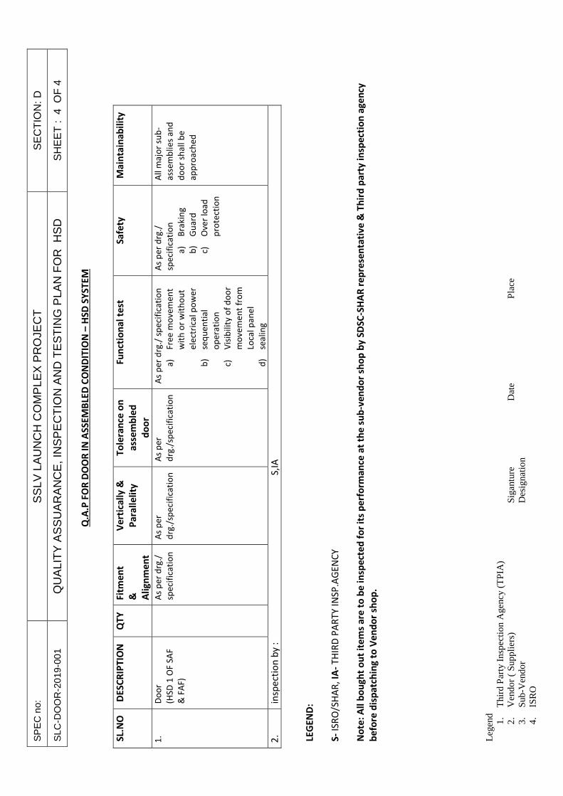
SP
EC
no:
S
SLV
LA
UN
CH
CO
MP
LEX
PR
OJE
CT
S
EC
TIO
N: D
SLC
-DO
OR
-201
9-00
1 Q
UA
LIT
Y A
SS
UA
RA
NC
E, I
NS
PE
CT
ION
AN
D T
ES
TIN
G P
LAN
FO
R H
SD
S
HE
ET
: 4
OF
4
Leg
end
1.
Thi
rd P
arty
Ins
pect
ion
Age
ncy
(TPI
A)
2.
Ven
dor
( Su
pplie
rs)
Si
gant
ure
D
ate
Pla
ce
3.
Sub-
Ven
dor
Des
igna
tion
4.
ISR
O
Q.A
.P F
OR
DO
OR
IN
AS
SE
MB
LED
CO
ND
ITIO
N –
HS
D S
YS
TE
M
SL.
NO
D
ES
CR
IPT
ION
Q
TY
F
itm
en
t
&
Ali
gn
me
nt
Ve
rtic
all
y &
Pa
rall
eli
ty
To
lera
nce
on
ass
em
ble
d
do
or
Fu
nct
ion
al
test
S
afe
ty
Ma
inta
ina
bil
ity
1.
Do
or
(HS
D 1
OF
SA
F
& F
AF
)
A
s p
er
drg
./
spe
cifi
cati
on
As
pe
r
drg
./sp
eci
fica
tio
n
As
pe
r
drg
./sp
eci
fica
tio
n
As
pe
r d
rg./
sp
eci
fica
tio
n
a)
Fre
e m
ov
em
en
t
wit
h o
r w
ith
ou
t
ele
ctri
cal
po
we
r
b)
seq
ue
nti
al
op
era
tio
n
c)
Vis
ibil
ity
of
do
or
mo
ve
me
nt
fro
m
Loca
l p
an
el
d)
sea
lin
g
As
pe
r d
rg./
spe
cifi
cati
on
a)
Bra
kin
g
b)
Gu
ard
c)
Ove
r lo
ad
pro
tect
ion
All
ma
jor
sub
-
ass
em
bli
es
an
d
do
or
sha
ll b
e
ap
pro
ach
ed
2.
insp
ect
ion
by
:
S
,IA
LEG
EN
D:
S-
ISR
O/S
HA
R,
IA-
TH
IRD
PA
RT
Y I
NS
P.A
GE
NC
Y
No
te:
All
bo
ug
ht
ou
t it
em
s a
re t
o b
e i
nsp
ect
ed
fo
r it
s p
erf
orm
an
ce a
t th
e s
ub
-ve
nd
or
sho
p b
y S
DS
C-S
HA
R r
ep
rese
nta
tiv
e &
Th
ird
pa
rty
in
spe
ctio
n a
ge
ncy
be
fore
dis
pa
tch
ing
to
Ve
nd
or
sho
p.

Spe
c. N
o.
SLC
-DO
OR
-201
9-00
1 S
SL
V L
AU
NC
H C
OM
PL
EX
PR
OJE
CT
SE
CT
ION
: D
QU
AL
ITY
AS
SU
RA
NC
E P
LA
N F
OR
SD
```S
heet
1
of
6
Leg
en
d :
VR
– V
en
do
r
IS
–
ISR
O
TP
– T
hir
d P
art
y I
nsp
ect
ion
Ag
en
cy
Sig
na
ture
S
ign
atu
re
S
ign
atu
re
D
ate
:
H –
Ca
rry
ing
ou
t re
spo
nsi
bil
ity
R –
Re
vie
w o
f re
cord
s &
re
sult
s
W –
Te
st/i
nsp
ect
ion
to
be
wit
ne
sse
d
Fo
r V
EN
DO
R
Fo
r T
HIR
D P
AR
TY
Fo
r IS
RO
Pla
ce :
SL.
NO
.
CO
MP
ON
EN
T/
OP
ER
AT
ION
CH
AR
AC
TE
RIS
TIC
S
TO
BE
CH
EC
KE
D
ME
TH
OD
OF
CH
EC
KIN
G
CA
TE
GO
RY
E
XT
EN
T O
F
CH
EC
K
RE
FE
RE
NC
E
DO
CU
ME
NT
S
AC
CE
PT
AN
CE
NO
RM
S
FO
RM
AT
OF
RE
CO
RD
S
INS
PE
CT
ION
AG
EN
CY
R
EM
AR
KS
VR
T
P
IS
A.
MA
TE
RIA
L (R
AW
MA
TE
RIA
LS &
BO
UG
HT
OU
TS
)
1
Ro
lle
d p
late
s &
sect
ion
s, F
org
ing
s
& C
ast
ing
s
a.
Ap
pe
ara
nce
V
isu
al
Ma
jor
10
0%
IS
:20
62
F
ree
do
m f
rom
de
fect
s li
ke
pit
tin
g,
cra
cks,
etc
.
--
H
H
R
b.
Pro
pe
rtie
s C
he
mic
al
an
aly
sis
&
ph
ysi
cal
test
Ma
jor
10
0%
IS
:20
62
D
raw
ing
,
spe
cifi
cati
on
Mil
l te
st
cert
ific
ate
s
/ La
b
rep
ort
s
H
R
R
c. I
nte
rna
l fl
aw
s U
T
Cri
tica
l 1
00
% f
or
pla
tes
≥20
mm
thic
k,
10
0%
fo
r
Ca
stin
gs
&
Fo
rgin
gs
AS
TM
A4
35
S
pe
cifi
cati
on
N
DT
rep
ort
s
H
H
R
2
Fa
ste
ne
rs (
hig
h
ten
sile
bo
lts
&
nu
ts e
tc.)
a.
Qu
ali
ty
Vis
ua
l M
ajo
r S
am
ple
ch
eck
as
pe
r re
lev
an
t
spe
cifi
cati
on
IS:1
36
7
a.
No
cra
cks
b.
Pro
pe
r
ma
tch
ing
wit
h n
uts
IR
H
W
R
b.
Ch
em
ica
l co
mp
osi
tio
n
& p
hy
sica
l p
rop
ert
ies
Ch
em
ica
l
an
aly
sis,
me
cha
nic
al
test
Ma
jor
Sa
mp
le c
he
ck
as
pe
r re
lev
an
t
spe
cifi
cati
on
IS:1
36
7
IS:1
36
7
Pa
rt I
II
Ma
nu
fac-
ture
r’s
test
cert
ific
ate
s
H
R
R
c. D
ime
nsi
on
al
Me
asu
re-
me
nts
Ma
jor
Sa
mp
le c
he
ck
as
pe
r re
lev
an
t
spe
cifi
cati
on
IS:1
36
7
IS:1
36
7
Pa
rt I
II &
XII
I
H
W
R
3
Hy
dra
uli
c R
ota
ry
Act
ua
tor,
Hy
dra
uli
c P
ow
er
Pa
ck
Dim
en
sio
na
l
con
form
an
ce
Me
asu
re-
me
nts
Ma
jor
10
0%
A
s p
er
Ma
nu
fact
ure
r’s
Sp
eci
fica
tio
n
As
pe
r
Ma
nu
fact
ure
r’s
Sp
eci
fica
tio
n
IR
H
W
R
Pe
rfo
rma
nce
Te
sts
Ve
rifi
cati
on
M
ajo
r 1
00
%
As
pe
r
Ma
nu
fact
ure
r’s
Sp
eci
fica
tio
n
As
pe
r
Ma
nu
fact
ure
r’s
Sp
eci
fica
tio
n
IR
H
W
R

Spe
c. N
o.
SLC
-DO
OR
-201
9-00
1 S
SL
V L
AU
NC
H C
OM
PL
EX
PR
OJE
CT
SE
CT
ION
: D
QU
AL
ITY
AS
SU
RA
NC
E P
LA
N F
OR
SD
```S
heet
2
of
6
Leg
en
d :
VR
– V
en
do
r
IS
–
ISR
O
TP
– T
hir
d P
art
y I
nsp
ect
ion
Ag
en
cy
Sig
na
ture
S
ign
atu
re
S
ign
atu
re
D
ate
:
H –
Ca
rry
ing
ou
t re
spo
nsi
bil
ity
R –
Re
vie
w o
f re
cord
s &
re
sult
s
W –
Te
st/i
nsp
ect
ion
to
be
wit
ne
sse
d
Fo
r V
EN
DO
R
Fo
r T
HIR
D P
AR
TY
Fo
r IS
RO
Pla
ce :
SL.
NO
.
CO
MP
ON
EN
T/
OP
ER
AT
ION
CH
AR
AC
TE
RIS
TIC
S
TO
BE
CH
EC
KE
D
ME
TH
OD
OF
CH
EC
KIN
G
CA
TE
GO
RY
E
XT
EN
T O
F
CH
EC
K
RE
FE
RE
NC
E
DO
CU
ME
N
TS
AC
CE
PT
AN
CE
NO
RM
S
FO
RM
AT
OF
RE
CO
RD
S
INS
PE
CT
ION
AG
EN
CY
R
EM
AR
KS
V
R
TP
IS
B.
WE
LDIN
G P
RO
CE
DU
RE
, W
ELD
ER
’S Q
UA
LIF
ICA
TIO
N,
ET
C.
1
We
ldin
g
WP
S,
We
lde
r’s
&
We
ldin
g o
pe
rato
r’s
qu
ali
fica
tio
n
Te
st p
iece
,
Vis
ua
l,
Ph
ysi
cal
&
ND
T (
RT
)
Cri
tica
l 1
00
%
AS
ME
Se
c
IX
AS
ME
Se
c IX
W
PS
, P
QR
&
WP
Q
H
H
R
C.
FA
BR
ICA
TIO
N (
Sw
ing
ing
Do
or
stru
ctu
re,
Hin
ge
Bra
cke
ts e
tc.)
1
Se
ttin
g o
ut
/
Lay
ou
t /
Ma
rkin
g
/ C
NC
pro
gra
mm
ing
Lay
ou
t M
ea
sure
me
nt
Ma
jor
10
0%
R
ele
va
nt
dra
win
gs
Fu
ll s
cale
la
yo
ut
to b
e
che
cke
d b
efo
re c
utt
ing
Sh
op
reg
iste
r
H
W
R
2
Fit
up
be
fore
we
ldin
g.
Qu
ali
ty
Vis
ua
l
ali
gn
me
nt
&
che
ck o
f
ma
jor
dim
en
sio
ns
Ma
jor
10
0%
D
raw
ing
s a
. p
rop
er
ed
ge
pre
pa
rati
on
b. p
rop
er
tack
we
lds
c. m
inim
um
ga
p f
or
bu
tt j
oin
ts a
s p
er
WP
S
d. D
IN-8
57
0
IR
H
H
R
Me
mb
ers
req
uir
ing
sit
e
we
ldin
g s
ha
ll
be
ma
tch
ma
rke
d a
t
join
ing
en
ds
for
site
ere
ctio
n
3
We
ldin
g (
fill
et
join
ts)
Pro
file
, fi
lle
t si
ze,
ov
era
ll
ph
ysi
cal
ap
pe
ara
nce
Vis
ua
l/ g
au
ge
,
DP
/ M
PT
aft
er
fin
al
we
ldin
g
Ma
jor
10
0%
A
SM
E
Se
cVII
I,
Vo
l-1
Dra
win
gs
IR
H
W
R
10
% D
P t
est
at
ran
do
m s
ha
ll
be
do
ne
4
Fu
ll p
en
etr
ati
on
we
ldin
g
a.
Ro
ot
insp
ect
ion
aft
er
ba
ck g
ou
gin
g
Vis
ua
l &
LP
I M
ajo
r 1
00
%
IS:3
65
8
No
cra
cks
all
ow
ed
IR
H
W
R
b.
Inte
rna
l d
efe
cts
UT
/ R
T
Cri
tica
l W
he
rev
er
ask
ed
in
th
e
dra
win
g
AS
ME
Se
c-
VII
I, V
ol-
1
AS
ME
Se
c-V
III,
Vo
l-1
T
est
re
po
rt
H
W
R

Spe
c. N
o.
SLC
-DO
OR
-201
9-00
1 S
SL
V L
AU
NC
H C
OM
PL
EX
PR
OJE
CT
SE
CT
ION
: D
QU
AL
ITY
AS
SU
RA
NC
E P
LA
N F
OR
SD
```S
heet
3
of
6
Leg
en
d :
VR
– V
en
do
r
IS
–
ISR
O
TP
– T
hir
d P
art
y I
nsp
ect
ion
Ag
en
cy
Sig
na
ture
S
ign
atu
re
S
ign
atu
re
D
ate
:
H –
Ca
rry
ing
ou
t re
spo
nsi
bil
ity
R –
Re
vie
w o
f re
cord
s &
re
sult
s
W –
Te
st/i
nsp
ect
ion
to
be
wit
ne
sse
d
Fo
r V
EN
DO
R
Fo
r T
HIR
D P
AR
TY
Fo
r IS
RO
Pla
ce :
SL.
NO
.
CO
MP
ON
EN
T/
OP
ER
AT
ION
CH
AR
AC
TE
RIS
TIC
S
TO
BE
CH
EC
KE
D
ME
TH
OD
OF
CH
EC
KIN
G
CA
TE
GO
RY
E
XT
EN
T O
F
CH
EC
K
RE
FE
RE
NC
E
DO
CU
ME
N
TS
AC
CE
PT
AN
CE
NO
RM
S
FO
RM
AT
OF
RE
CO
RD
S
INS
PE
CT
ION
AG
EN
CY
R
EM
AR
KS
V
R
TP
IS
c. W
eld
ing
qu
ali
ty,
surf
ace
de
fect
s
LPI
/ M
PI
Cri
tica
l W
he
rev
er
ask
ed
in
th
e
dra
win
g
AS
ME
Se
c-
VII
I, V
ol-
1
AS
ME
Se
c-V
III,
Vo
l-1
T
est
re
po
rt
H
H
R
5
Str
ess
re
lie
vin
g
(aft
er
com
ple
te
we
ldin
g)
T-T
cu
rve
s T
-T c
urv
e
ve
rifi
cati
on
Ma
jor
10
0%
A
SM
E S
ec-
VII
I, V
ol-
I
Dra
win
gs
T-T
gra
ph
H
R
R
6
Dim
en
sio
na
l
insp
ect
ion
aft
er
we
ldin
g &
str
ess
reli
ev
ing
Dim
en
sio
na
l M
ea
sure
me
nt
of
ma
jor
dim
en
sio
ns
&
full
siz
e s
ho
p
lay
ou
t
che
ckin
g
Ma
jor
10
0%
D
raw
ing
/
DIN
85
70
Dra
win
gs
IR
H
H
W
D.
GR
IT B
LAS
TIN
G &
PA
INT
ING
1
Gri
t b
last
ing
&
pa
inti
ng
Pa
int
thic
kn
ess
V
isu
al
&
me
asu
rem
en
t
by
pa
int
thic
kn
ess
ga
ug
e
Ma
jor
At
ran
do
m f
or
pa
int
thic
kn
ess
Dra
win
g &
spe
cifi
cati
on
Dra
win
gs
&
spe
cifi
cati
on
IR
H
W
R
E.
MA
CH
ININ
G (
Dri
ve
Hin
ge
, Id
le H
ing
e,
Hin
ge
Bra
cke
ts,
Cy
clo
ne
Lo
cks
etc
.)
1
Ma
chin
ing
Ov
era
ll d
ime
nsi
on
s
Me
asu
rem
en
t
& v
isu
al
Ma
jor
10
0%
Dra
win
g
Dra
win
g
IR
H
H
R

Spe
c. N
o.
SLC
-DO
OR
-201
9-00
1 S
SL
V L
AU
NC
H C
OM
PL
EX
PR
OJE
CT
SE
CT
ION
: D
QU
AL
ITY
AS
SU
RA
NC
E P
LA
N F
OR
SD
```S
heet
4
of
6
Leg
en
d :
VR
– V
en
do
r
IS
–
ISR
O
TP
– T
hir
d P
art
y I
nsp
ect
ion
Ag
en
cy
Sig
na
ture
S
ign
atu
re
S
ign
atu
re
D
ate
:
H –
Ca
rry
ing
ou
t re
spo
nsi
bil
ity
R –
Re
vie
w o
f re
cord
s &
re
sult
s
W –
Te
st/i
nsp
ect
ion
to
be
wit
ne
sse
d
Fo
r V
EN
DO
R
Fo
r T
HIR
D P
AR
TY
Fo
r IS
RO
Pla
ce :
SL.
NO
.
CO
MP
ON
EN
T/
OP
ER
AT
ION
CH
AR
AC
TE
RIS
TIC
S
TO
BE
CH
EC
KE
D
ME
TH
OD
OF
CH
EC
KIN
G
CA
TE
GO
RY
E
XT
EN
T O
F
CH
EC
K
RE
FE
RE
NC
E
DO
CU
ME
NT
S
AC
CE
PT
AN
CE
NO
RM
S
FO
RM
AT
OF
RE
CO
RD
S
INS
PE
CT
ION
AG
EN
CY
R
EM
AR
KS
VR
T
P
IS
2
Dri
llin
g,
etc
.
Dri
llin
g &
ta
pp
ing
Me
asu
rem
en
t
of
ho
le s
ize
&
cen
ter
dis
tan
ces
Cri
tica
l
10
0%
Dra
win
g &
DIN
85
70
Dra
win
g
IR
H
H
R
F.
CO
NT
RO
L A
SS
EM
BLY
of
Sw
ing
ing
Do
or,
Dri
ve
Hin
ge
, Id
le H
ing
e,
Cy
clo
ne
Lo
ck,
Hy
dra
uli
c A
ctu
ato
r, H
ydra
uli
c P
ow
er
Pa
ck e
tc.
AT
SH
OP
1
Co
ntr
ol
ass
em
bly
at
wo
rks
a)
Dim
ensi
ons
, L
evel
ing,
A
lign
men
t of
D
rive
H
inge
, Id
le
Hin
ge
syst
ems
etc.
, va
riou
s cl
eara
nces
, su
rfac
e fi
nish
et
c as
sp
ecif
ied
in d
raw
ings
.
Vis
ua
l &
me
asu
rem
en
t
Cri
tica
l
10
0%
Dra
win
g
Dra
win
gs
IR
H
H
H
Be
fore
dis
ma
ntl
ing
,
refe
ren
ce l
ine
an
d m
atc
h
ma
rkin
g t
o b
e
pu
nch
ed
.
b)
Fre
e ro
tati
onal
mov
emen
t of
sw
ingi
ng
Doo
rs
abou
t tw
o H
inge
s,
Vis
ua
l &
me
asu
rem
en
t
Cri
tica
l
10
0%
Dra
win
g
Dra
win
gs
IR
H
H
H
Be
fore
dis
ma
ntl
ing
,
refe
ren
ce l
ine
an
d m
atc
h
ma
rkin
g t
o b
e
pu
nch
ed
.
c)
No
load
ru
nnin
g te
st
of
Hyd
raul
ic
Rot
ary
Act
uato
r .
Vis
ua
l &
me
asu
rem
en
t
Cri
tica
l
10
0%
Dra
win
g
Dra
win
gs
IR
H
H
H
Be
fore
dis
ma
ntl
ing
,
refe
ren
ce l
ine
an
d m
atc
h
ma
rkin
g t
o b
e
pu
nch
ed
.

Spe
c. N
o.
SLC
-DO
OR
-201
9-00
1 S
SL
V L
AU
NC
H C
OM
PL
EX
PR
OJE
CT
SE
CT
ION
: D
QU
AL
ITY
AS
SU
RA
NC
E P
LA
N F
OR
SD
```S
heet
5
of
6
Leg
en
d :
VR
– V
en
do
r
IS
–
ISR
O
TP
– T
hir
d P
art
y I
nsp
ect
ion
Ag
en
cy
Sig
na
ture
S
ign
atu
re
S
ign
atu
re
D
ate
:
H –
Ca
rry
ing
ou
t re
spo
nsi
bil
ity
R –
Re
vie
w o
f re
cord
s &
re
sult
s
W –
Te
st/i
nsp
ect
ion
to
be
wit
ne
sse
d
Fo
r V
EN
DO
R
Fo
r T
HIR
D P
AR
TY
Fo
r IS
RO
Pla
ce :
SL.
NO
.
CO
MP
ON
EN
T/
OP
ER
AT
ION
CH
AR
AC
TE
RIS
TIC
S
TO
BE
CH
EC
KE
D
ME
TH
OD
OF
CH
EC
KIN
G
CA
TE
GO
RY
E
XT
EN
T O
F
CH
EC
K
RE
FE
RE
NC
E
DO
CU
ME
NT
S
AC
CE
PT
AN
CE
NO
RM
S
FO
RM
AT
OF
RE
CO
RD
S
INS
PE
CT
ION
AG
EN
CY
R
EM
AR
KS
V
R
TP
IS
G.
ER
EC
TIO
N A
T S
ITE
1
Fa
bri
cate
d
ma
teri
al
insp
ect
ion
Vis
ua
l, d
ime
nsi
on
al,
rev
iew
of
TC
& I
R
Vis
ua
l &
me
asu
rem
en
t
Ma
jor
10
0%
TS
&
ap
pro
ve
d
dra
win
gs
TS
& a
pp
rov
ed
dra
win
gs
IR
H
R
R
2
We
ldin
g &
we
lde
r
qu
ali
fica
tio
n
WP
S,
We
lde
r’s
&
We
ldin
g o
pe
rato
r’s
qu
ali
fica
tio
n
Te
st p
iece
,
Vis
ua
l, P
hy
sica
l
& N
DT
(R
T)
Cri
tica
l
10
0%
AS
ME
Se
c
IX
AS
ME
Se
c IX
WP
S,
PQ
R &
WP
Q
H
W
R
3
Po
siti
on
ing
&
ali
gn
me
nt
of
Hin
ge
Bra
cke
ts,
Sw
ing
Do
or
stru
ctu
re,
Hy
dra
uli
c R
ota
ry
Act
ua
tors
&
Hy
dra
uli
c P
ow
er
Pa
ck,
etc
.
Po
siti
on
, le
ve
l, a
lig
nm
en
t
an
d o
the
r d
ime
nsi
on
s.
Me
asu
rem
en
t
& v
isu
al
Ma
jor
10
0%
D
raw
ing
D
raw
ing
IR
H
H
H
4
We
ldin
g
Pre
he
at
/ in
terp
ass
/
seq
ue
nce
of
we
ldin
g
Vis
ua
l M
ajo
r 1
00
%
Dra
win
g &
TS
Dra
win
g &
TS
IR
H
H
H
5
Str
ess
re
lie
vin
g
T-T
cu
rve
s T
-T c
urv
es,
cha
rts
Cri
tica
l 1
00
%
Dra
win
g &
TS
Dra
win
gs
& T
S
IR
H
H
H
6
Co
mp
lete
we
ldin
g
Vis
ua
l, D
PT
, U
T
Vis
ua
l &
UT
M
ajo
r 1
00
%
TS
&
dra
win
gs
TS
& d
raw
ing
s IR
H
H
H

Spe
c. N
o.
SLC
-DO
OR
-201
9-00
1 S
SL
V L
AU
NC
H C
OM
PL
EX
PR
OJE
CT
SE
CT
ION
: D
QU
AL
ITY
AS
SU
RA
NC
E P
LA
N F
OR
SD
```S
heet
6
of
6
Leg
en
d :
VR
– V
en
do
r
IS
–
ISR
O
TP
– T
hir
d P
art
y I
nsp
ect
ion
Ag
en
cy
Sig
na
ture
S
ign
atu
re
S
ign
atu
re
D
ate
:
H –
Ca
rry
ing
ou
t re
spo
nsi
bil
ity
R –
Re
vie
w o
f re
cord
s &
re
sult
s
W –
Te
st/i
nsp
ect
ion
to
be
wit
ne
sse
d
Fo
r V
EN
DO
R
Fo
r T
HIR
D P
AR
TY
Fo
r IS
RO
Pla
ce :
7
Dim
en
sio
na
l
che
ck o
f w
ho
le
ass
em
bly
Po
siti
on
, le
ve
l,
ali
gn
me
nt
an
d o
the
r
dim
en
sio
ns,
cle
ara
nce
s
Me
asu
rem
en
t
& V
isu
al
Ma
jor
10
0%
D
raw
ing
s D
raw
ing
s IR
H
H
H
8
Ro
tati
on
al
mo
ve
me
nt
of
all
swin
gin
g D
oo
rs(
7 n
os
in
SA
F &
3
no
s i
s F
AF
),
min
imu
m
dis
tan
ce
be
twe
en
an
y
two
Do
ors
Cle
ara
nce
s V
isu
al
&
me
asu
rem
en
t,
smo
oth
mo
ve
me
nt
wit
ho
ut
jerk
s
thro
ug
ho
ut
the
ra
ng
e o
f
tra
ve
l.
Ma
jor
10
0%
T
S &
dra
win
gs
TS
& d
raw
ing
s IR
H
H
H

SP
EC
no:
S
SLV
LA
UN
CH
CO
MP
LEX
PR
OJE
CT
S
EC
TIO
N: D
SLC
-DO
OR
-201
9-00
1 Q
UA
LIT
Y A
SS
UA
RA
NC
E, I
NS
PE
CT
ION
AN
D T
ES
TIN
G P
LAN
FO
R S
LD
SH
EE
T :
1 O
F 4
Leg
end
1.
Thi
rd P
arty
Ins
pect
ion
Age
ncy
(TPI
A)
2.
Ven
dor
(Sup
plie
rs)
Si
gant
ure
D
ate
Pla
ce
3.
Sub-
Ven
dor
Des
igna
tion
4.
ISR
O
Q.A
.P F
OR
FA
BR
ICA
TE
D I
TE
MS
– S
LD S
YS
TE
M
SL
N
o.
IT
EM
M
AT
ER
IAL
W
EL
DIN
G
FIN
AL
M
AC
HIN
ING
Q
T Y
CT
M
T
SUR
FA
CE
Q
UA
LIT
Y
INT
ER
NA
L
QU
AL
ITY
D
R
OO
T
LP1
/MP
1
FIN
AL
LP
1/M
P1
V
R T
UT
O
TH
ER
D
& S D
& S
1.
Doo
r st
ruct
ure
R
R
V
isua
l U
T o
n pl
ates
R
A
LL
Jts
. C
riti
cal J
ts.
R
- U
T o
n bu
ilt
up s
urfa
ce
R
R
2.
Top
Gui
de
Whe
el B
rack
et
R
R
V
isua
l U
T o
n pl
ates
R
A
LL
Jts
. C
riti
cal J
ts.
R
- U
T o
n bu
ilt
up s
urfa
ce
TT
R
R
R
3.
Rai
n H
ood
R
R
V
isua
l U
T o
n pl
ates
R
A
LL
Jts
. C
riti
cal J
ts.
R
- U
T o
n bu
ilt
up s
urfa
ce
R
R
4.
Sol
e P
late
R
R
Vis
ual
UT
on
plat
es
R
AL
L J
ts.
AL
L J
ts.
R
- U
T o
n bu
ilt
up s
urfa
ce
R
R
5.
Cyc
lone
Loc
k
R
R
Vis
ual
UT
on
plat
es
R
AL
L J
ts.
Cri
tica
l Jts
. R
-
UT
on
buil
t up
sur
face
T
TR
R
R
In
spec
tion
by
S,IA
S,
IA
LEG
EN
D:
R:
RE
QU
IRE
D,
CT
: C
HE
MIC
AL
TE
ST
, M
T:
ME
CH
INIC
AL,
D:
DIM
EN
SIO
NA
L A
CC
UR
AC
Y,
LPI:
LIQ
UID
PE
NE
TR
AN
T I
NS
PE
CT
ION
MP
I: M
AG
NE
TIC
PA
RT
ICA
L IN
SP
EC
TIO
N,
V:
VIS
UA
L IN
SP
EC
TIO
N,
RT
: R
AD
IOG
RA
PH
IC I
NS
PE
CT
ION
, U
T:
ULT
RA
SO
NIC
IN
SP
EC
TIO
N
D&
S:
DIM
EN
SIO
NA
L A
CC
UR
AC
Y A
ND
SU
RF
AC
E F
INIS
H,
TT
R:
TIM
E T
EM
PE
RA
TU
RE
RE
CO
RD
S,
S-I
SR
O/S
HA
R,
IA-T
HIR
D P
AR
TY
IN
SP
.AG
EN
CY
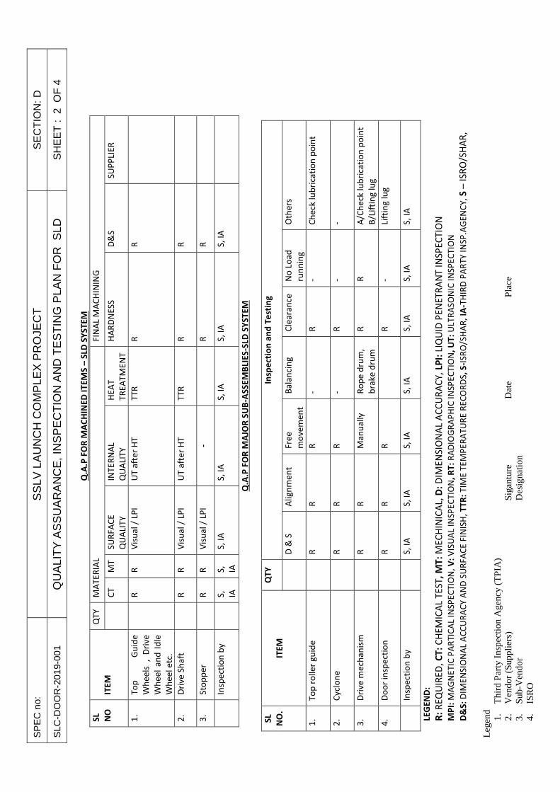
SP
EC
no:
S
SLV
LA
UN
CH
CO
MP
LEX
PR
OJE
CT
S
EC
TIO
N: D
SLC
-DO
OR
-201
9-00
1 Q
UA
LIT
Y A
SS
UA
RA
NC
E, I
NS
PE
CT
ION
AN
D T
ES
TIN
G P
LAN
FO
R S
LD
SH
EE
T :
2 O
F 4
Leg
end
1.
Thi
rd P
arty
Ins
pect
ion
Age
ncy
(TPI
A)
2.
Ven
dor
(Sup
plie
rs)
Si
gant
ure
D
ate
Pla
ce
3.
Sub-
Ven
dor
Des
igna
tion
4.
ISR
O
Q.A
.P F
OR
MA
CH
INE
D I
TE
MS
– S
LD S
YS
TE
M
SL
NO
ITE
M
QT
Y
MA
TE
RIA
L F
INA
L M
AC
HIN
ING
C
T
MT
S
UR
FA
CE
QU
ALI
TY
INT
ER
NA
L
QU
ALI
TY
HE
AT
TR
EA
TM
EN
T
HA
RD
NE
SS
D
&S
S
UP
PLI
ER
1.
To
p
Gu
ide
Wh
ee
ls
, D
rive
Wh
ee
l a
nd
Id
le
Wh
ee
l e
tc.
R
R
V
isu
al
/ LP
I U
T a
fte
r H
T
TT
R
R
R
2.
Dri
ve
Sh
aft
R
R
Vis
ua
l /
LPI
UT
aft
er
HT
T
TR
R
R
3.
Sto
pp
er
R
R
V
isu
al
/ LP
I -
R
R
In
spe
ctio
n b
y
S
,
IA
S,
IA
S,
IA
S,
IA
S,
IA
S,
IA
S,
IA
Q.A
.P F
OR
MA
JOR
SU
B-A
SS
EM
BLI
ES
-SLD
SY
ST
EM
S
L
NO
.
ITE
M
QT
Y
Insp
ect
ion
an
d T
est
ing
D
& S
A
lig
nm
en
t
Fre
e
mo
ve
me
nt
Ba
lan
cin
g
Cle
ara
nce
N
o L
oa
d
run
nin
g
Oth
ers
1.
To
p r
oll
er
gu
ide
R
R
R
- R
-
Ch
eck
lu
bri
cati
on
po
int
2.
Cy
clo
ne
R
R
R
- R
-
-
3.
Dri
ve
me
cha
nis
m
R
R
M
an
ua
lly
R
op
e d
rum
,
bra
ke
dru
m
R
R
A/C
he
ck l
ub
rica
tio
n p
oin
t
B/L
ifti
ng
lu
g
4.
Do
or
insp
ect
ion
R
R
R
R
-
Lift
ing
lu
g
In
spe
ctio
n b
y
S
, IA
S
, IA
S
, IA
S
, IA
S
, IA
S
, IA
S
, IA
LEG
EN
D:
R:
RE
QU
IRE
D,
CT
: C
HE
MIC
AL
TE
ST,
MT
: M
EC
HIN
ICA
L, D
: D
IME
NS
ION
AL
AC
CU
RA
CY
, LP
I: L
IQU
ID P
EN
ET
RA
NT
IN
SP
EC
TIO
N
MP
I: M
AG
NE
TIC
PA
RT
ICA
L IN
SP
EC
TIO
N,
V:
VIS
UA
L IN
SP
EC
TIO
N,
RT
: R
AD
IOG
RA
PH
IC I
NS
PE
CT
ION
, U
T:
ULT
RA
SO
NIC
IN
SP
EC
TIO
N
D&
S:
DIM
EN
SIO
NA
L A
CC
UR
AC
Y A
ND
SU
RF
AC
E F
INIS
H,
TT
R:
TIM
E T
EM
PE
RA
TU
RE
RE
CO
RD
S,
S-I
SR
O/S
HA
R,
IA-T
HIR
D P
AR
TY
IN
SP
.AG
EN
CY
, S
– I
SR
O/S
HA
R,

SP
EC
no:
S
SLV
LA
UN
CH
CO
MP
LEX
PR
OJE
CT
S
EC
TIO
N: D
SLC
-DO
OR
-201
9-00
1 Q
UA
LIT
Y A
SS
UA
RA
NC
E, I
NS
PE
CT
ION
AN
D T
ES
TIN
G P
LAN
FO
R S
LD
SH
EE
T :
3 O
F 4
Leg
end
1.
Thi
rd P
arty
Ins
pect
ion
Age
ncy
(TPI
A)
2.
Ven
dor
(Sup
plie
rs)
Si
gant
ure
D
ate
Pla
ce
3.
Sub-
Ven
dor
Des
igna
tion
4.
ISR
O
Q.A
.P F
OR
DO
OR
IN
AS
SE
MB
LED
CO
ND
ITIO
N –
SLD
SY
ST
EM
S
L.N
O
DE
SC
RIP
TIO
N
QT
Y
Fit
me
nt
&
Ali
gn
me
nt
Ve
rtic
all
y &
Pa
rall
eli
ty
To
lera
nce
on
ass
em
ble
d
do
or
Fu
nct
ion
al
test
S
afe
ty
Ma
inta
ina
bil
ity
1.
Do
or
(SLD
1 O
F F
AF
)
A
s p
er
drg
./
spe
cifi
cati
on
As
pe
r
drg
./sp
eci
fica
tio
n
As
pe
r
drg
./sp
eci
fica
tio
n
As
pe
r d
rg.
/ sp
eci
fica
tio
n
a)
Fre
e m
ov
em
en
t
wit
h o
r w
ith
ou
t
ele
ctri
cal
po
we
r
b)
seq
ue
nti
al
op
era
tio
n
c)
Vis
ibil
ity
of
do
or
mo
ve
me
nt
fro
m
Loca
l p
an
el
d)
sea
lin
g
As
pe
r d
rg.
/
spe
cifi
cati
on
a)
Bra
kin
g
b)
Gu
ard
c)
Ove
r lo
ad
pro
tect
ion
All
ma
jor
sub
-
ass
em
bli
es
an
d
do
or
sha
ll b
e
ap
pro
ach
ed
2.
insp
ect
ion
by
:
S
,IA
LEG
EN
D:
S-
ISR
O/S
HA
R,
IA-
TH
IRD
PA
RT
Y I
NS
P.A
GE
NC
Y
No
te:
All
bo
ug
ht
ou
t it
em
s a
re t
o b
e i
nsp
ect
ed
fo
r it
s p
erf
orm
an
ce a
t th
e s
ub
-ve
nd
or
sho
p b
y S
DS
C-S
HA
R r
ep
rese
nta
tiv
e &
Th
ird
pa
rty
in
spe
ctio
n a
ge
ncy
be
fore
dis
pa
tch
ing
to
Ve
nd
or
sho
p.

SPEC.NO. SSLV LAUNCH COMLEX PROJECT SECTION: E SLC-DOOR-2019-001 WELDING SPECFICATIONS FOR SHOP AND SITE
FABRICATED EQUIPMENT SHEET : 1 OF 17
1.0 SCOPE
This specification shall apply to shop and site fabrication of all welded joints in carbon steel. Low alloy steel and stainless steel equipment like pressure vessels, tank, columns and heat exchangers etc. The specification shall apply to all the joints indicated below: (a) Butt joints produced by double sided welding which produce the same quality
of deposited weld metal on both inside and outside weld surfaces.
(b) Butt joints produced by single sided welding having backing strip which remains in place and full penetration butt weld without backing strip
(c) Corner or those joints connecting two (2) members approximately at right
angles to each other in the form of L or T
(d) Partial penetration welds of the groove type which are used for connections not subjected to external loading
(e) Fillet welded joints of approximately triangular cross-section joining two (2)
surfaces at approximately right angles to each other and having a throat dimension at least 70% of the thinner of the parts being joined but not less than 6mm
(f) Welds attaching nozzles and other connections
(g) Welds which are used to join non-pressure parts like supports, lugs,
brackets, stiffeners and other attachments to the vessel wall
(h) Any other similar joint which is not specified above but may be encountered during fabrication
2.0 CODES AND STANDARDS
2.1 The welding equipment, welding consumables, preheating, Postweld Heat Treatment (PWHT), other auxiliary functions and welding personnel shall comply with all currently applicable statutes, regulations and safety codes in the locality where the equipment are to be fabricated and installed. Nothing in this specification shall be construed to relive the VENDOR/CONTRACTOR of his responsibility. Specifically, the latest editions of the codes and standards listed below shall apply:
(a) ASME Boiler and Pressure Vessel Code (BPV Code), Section II Part C- Material Specification for Welding Rods. Electrodes, and Filler Metals
(b) ASME BPV Code, Section V-Non-destructive Examination(NDE)
(c) ASME BPV Code, Section VIII Division I-Rules for construction of Pressure Vessels
(d) ASME BPV Code, Section IX – Welding and Brazing Qualifications
(e) American Society of Non-destructive Testing (ASNT) SNT-TC-IA, Recommended Practice
(f) Indian Boiler Regulations (IBR)

SPEC.NO. SSLV LAUNCH COMLEX PROJECT SECTION: E SLC-DOOR-2019-001 WELDING SPECFICATIONS FOR SHOP AND SITE
FABRICATED EQUIPMENT SHEET : 2 OF 17
(g) Any other codes and standards specified in Section B, C & D of enquiry
specification
2.1.1 The codes and standards listed in para 2.1 form an integral part of this specification. In the event of conflict between this specification and the codes & standards, the more stringent shall govern.
2.1.2 If no specific requirements are given in this specification, the requirements of the applicable code shall govern.
3.0 WELDING PROCESSES
The following welding processes shall be used:
3.1 GAS TUNGSTEN ARC WELDING (GTAW)
3.1.1 The root pass of single-sided groove welds without backing
3.1.2 Full penetration nozzle connection where other side is inaccessible
3.1.3 Any butt and fillet weld on equipment with thickness 5 mm or less
3.1.4 For all passes of butt and fillet welding of nozzles on equipment and integral piping of size 50 mm NB or smaller
3.2 Shielded Metal-Arc Welding (SAW)\
3.3 SUBMERGED ARC WELDING (SAW)
Maximum weld deposit per pass shall be 12.7 mm for carbon steel (p-1) and 9.5 mm for other materials.
3.4 Gas Metal Arc Welding (GMAW) and Flux Cored Arc Welding (FCAW) processes
3.5 Other processes such as plasma-arc and electro-slag welding may be used only with the approval of the PURCHASER and depending upon the process and application proposed. These processes may require testing in addition to that specified by the governing procedure qualification code.
3.6 Table 1 gives recommendations for welding processes to be used for carbon, low alloy and austenitic stainless steels.
4.0 WELDING CONSUMABLES
4.1 The VENDOR/CONTRACTOR shall provide, at no additional cost, all the welding consumables such as electrodes, filler wires, flux, oxygen, acetylene, argon etc., in order to complete the welding in all respects. The consumables shall be from reputed and approved manufacturers. All the consumables shall be approved by the PURCHASER / TPI.
4.2 The electrodes and filler wires shall be of the class specified in Table 1 Welding specification chart.

SPEC.NO. SSLV LAUNCH COMLEX PROJECT SECTION: E SLC-DOOR-2019-001 WELDING SPECFICATIONS FOR SHOP AND SITE
FABRICATED EQUIPMENT SHEET : 3 OF 17
4.3 Electrodes qualification test records shall be submitted for the PURCHASER’S
approval. The VENDOR/CONTRACTOR shall also submit batch test certificates from the electrodes manufacturer for physical and chemical tests.
4.4 Electrodes shall be in sealed containers and adequate care shall be taken for storage, strictly in accordance with the manufacturer’s recommendations.
4.5 Electrodes, which have been removed from the original containers, shall be kept in baking ovens as per the manufacturer’s recommendations and, once these are taken out, shall be consumed within the time limits stipulated by the manufacturer. Care shall be taken in handling the electrodes to prevent any damage to the flux covering. Portable ovens shall be used for carrying the electrodes from the main oven to the field. Electrodes of different specifications shall be stored in different compartments of a baking oven to avoid mix up.
4.6 The electrodes, filler wires and flux used shall be free from contamination such as rust, oil, grease and such foreign matter.
4.7 Low hydrogen electrodes shall be used for weld joints in carbon steel if the wall thickness exceeds 19 mm and low alloy steel of all thickness except that non low hydrogen electrodes shall be permitted for the root pass of carbon steel only.
4.8 If ultimate tensile strength of base material permits, E 6010 electrodes may be used for root pass of butt welds and for fillet welds in carbon steel.
5.0 WELDING QUALIFICATIONS
5.1 Qualification of the welding procedures to be used and the performance of welders and welding operators shall conform to the requirements of the BPV Codes and Section IX. For equipment under the purview of IBR, these shall also meet the requirements of IBR.
5.2 No production welds shall be undertaken until the qualification requirements are completed to the satisfaction of the PURCHASER.
5.3 When impact testing is required by the code or by the specification, these requirements shall be met in qualifying welding procedures.
5.4 The VENDOR/CONTRACTOR shall be responsible for qualifying any welding procedure, welders and welding operators intended to be deployed. The VENDOR/CONTRACTOR shall submit the welding procedure specification (WPS) for acceptance by the PURCHASER. After approval by the PURCHASER, the procedure qualification test shall be carried out by the VENDOR/CONRACTOR, at his own expense, duly witnessed by the TPI / PURCHASER. A complete set of test results, in specified format, shall be submitted to the PURCHASER for approval immediately after successful completion of procedure qualification test. All tests as required by the BPV code Section IX or IBR shall be carried out. The WPS shall require re-qualification, if any of the essential variables of supplementary variable is altered.
5.5 Welders and welding operators shall be qualified in accordance with BPV code and Section IX or IBR, as applicable. The qualification shall be carried out in the presence of the PURCHASER / TPI. Only those welders and welding operators who are qualified shall be deployed on the job. For equipment under the purview

SPEC.NO. SSLV LAUNCH COMLEX PROJECT SECTION: E SLC-DOOR-2019-001 WELDING SPECFICATIONS FOR SHOP AND SITE
FABRICATED EQUIPMENT SHEET : 4 OF 17
of IBR, approval of the local IBR inspector shall be obtained by the VENDOR/CONTRACTOR.
5.6 Welders and welding operators shall always keep their identification cards with them and shall produce them on demand. The VENDOR/CONTRACTOR shall issue the identity cards after the same are duly certified by the PURCHASER Welder or welding operator, who is not in possession of the identity card, shall not be allowed to work.
5.7 The VENDOR/CONTRACTOR shall use forms as per BPV code, section IX, form QW-482, form QW-483 and form QW-484. Other forms are also acceptable subject to approval by the PURCHASER.
5.8 Unless agreed otherwise, the VENDOR/CONTRACTOR shall advise the PURCHASER, in writing, at least three (3) weeks before any welder or welding operator is deployed on the work, the names and qualification of the proposed welders, welding operators and welding supervisors. It shall be the VENDOR/CONRTRACTOR’S responsibility to ensure that all welders and welding operators employed by him or his SUB-VENDORS/SUB-CONTRACTORS at works or at site are fully qualified as required by the code. Each welder and welding operator shall qualify for all types of welds, positions and materials or material combinations he may be called upon to weld.
5.9 Should the PURCHASER require to qualify or requalify any welder or welding operator, the VENDOR/CONTRACTOR shall make available, at no extra cost to the PURCHASER the men, equipment and materials for the tests. The cost, of testing the welds shall be borne by the VENDOR/CONTRACTOR.
5.10 Welding supervisors shall have qualifications such as engineering degree or engineering diploma in welding technology with adequate knowledge of welding consumables welding machines & NDE and a minimum of five (5) years of experience in supervising welding of joints.
5.11 All welding, including the tacking up of welds shall be carried out by qualified welders and welding operators as per approved WPS. Any weld made by other than a qualified welder or welding operator or not carried out as per approved WPS shall be cut out and re-welded.
5.12 For purpose of identification and to enable tracing full history of each joint, each welder and welding operator employed on the work shall be given a designation. The welder and welding operator’s designation and the date on which the joint is made, shall be stamped near the relevant joint and on the relevant drawings also. Copies of the drawings so marked shall be furnished to the PURCHASER for record purposes.
5.13 For each welder and welding operator, a record card shall be maintained showing the procedures for which he is qualified. These cards shall note the production welds, the date of the welding done, the type of defects produced and their frequency. The record shall be reviewed once in a week by the PURCHASER and those welders & welding operators whose work required a disproportionate amount of repair shall be disqualified from welding. Re-qualification of welders and welding operators disqualified more than three (3) times shall be entirely at the discretion of the PURCHASER. As far as possible,

SPEC.NO. SSLV LAUNCH COMLEX PROJECT SECTION: E SLC-DOOR-2019-001 WELDING SPECFICATIONS FOR SHOP AND SITE
FABRICATED EQUIPMENT SHEET : 5 OF 17
the qualification shall be carried out at the location (site or shop) where the actual fabrication and welding work is to be carried out.
6.0 PERPARATION FOR WELDING
6.1` Surface to be welded shall be smooth uniform and free from fins, tears and other defects, which would adversely affect the quality of the weld. All welding faces and adjoining surfaces, for a distance of at least 50 mm from the edge of the welding groove or 12 mm from the toe of the fillet in the case of socket welded or fillet welded joints, shall be thoroughly cleaned of rust, scale, paint, oil or grease, on both inside and outside.
6.2 Joints for welding shall be as per the project specifications and approved fabrication drawings.
6.3 Butt joints shall be prepared as per ASME BPV code Section VIII Division 1, unless specified otherwise. For equipment under the purview of IBR, these shall be as per IBR. Any other end preparation which meets the WPS is acceptable.
6.4 Internal misalignment shall be reduced by trimming but such trimming shall not reduce the finished wall thickness below the required minimum wall thickness. Trimming shall not be abrupt. It shall be tapered with a minimum slope of 1:3. Root opening of the joint shall be within the tolerance limits of the WPS.
6.5 Welds shall be as per ASME BPV code section VIII Division 1 or in accordance with IBR for equipment under the purview of IBR
6.6 Reinforcing pads and saddles shall have a good fit with the parts to which they are attached. A tell-tale hole shall be provided on the side of any pad or saddle to reveal leakage in the weld and to allow venting during welding and heat treatment. Pad or saddle shall be added, after the branch weld has undergone satisfactory visual and NDE.
6.7 The ends shall be prepared by machining, grinding, flame cutting or plasma cutting. Where flame cutting is used, the effect on the mechanical and metallurgical properties of the base metal shall be taken into consideration. Flame cutting of alloy steel is not advisable. If alloy steel is cut using flame, the heat affected zone shall be removed completely by grinding and/or machining. Magnetic Particle (MT) or Liquid Penetrant (PT) testing shall be carried out to ensure soundness of edges. However, flame cutting of carbon steel is permitted. Wherever practicable, flame cutting shall be carried out by machine shall be cleaned free of slag. Manual flame cutting shall be permitted only where machine flame cutting is not practicable and with the approval of the PURCHASER, and such surfaces shall be ground or dressed to a smooth finish as required by the specification and to the satisfaction of the PURCHASER. Slag, scale or oxides shall be removed by grinding to bright metal at least two (2) mm beyond the burnt area.
6.8 Thermal cutting of carbon steel shall be performed under the same conditions of preheating and PWHT as for the welding of each class of material. However, PWHT is not required when:
(a) The heat affected zone produced by thermal cutting is removed by mechanical means immediately after cutting. However, in any case, all remaining slag, scale or oxides shall be removed by grinding to bright metal at least two (2) mm beyond the burnt area, or

SPEC.NO. SSLV LAUNCH COMLEX PROJECT SECTION: E SLC-DOOR-2019-001 WELDING SPECFICATIONS FOR SHOP AND SITE
FABRICATED EQUIPMENT SHEET : 6 OF 17
(b) Thermal cutting is part of fabrication, manufacturing or erection sequence
leading to a weld end preparation where welding immediately follows.
6.9 Before fitting up the weld joint, the profile and dimensions of the weld end preparation shall be checked by the PURCHASER. If the specified tolerances are exceeded, this shall be corrected (with prior approval) by grinding, machining or any other method acceptable to the PURCHASER.
6.11 Fit-ups shall be examined by the PURCHASER prior to welding the root pass.
7.0 TECHNIQUE AND WORKMANSHIP
7.1 Components to be welded shall be aligned and spaced as per the requirements of the code and WPS.
7.3 Alignment and spacing shall be achieved using suitable wires to maintain the gap. These shall be removed after tack welding. The ends to be welded shall be held using suitable clamps, yokes or other devices which will not damage the surfaces in any manner. It shall be ensured that welding operations do not result in distortions.
7.4 Earthing shall be provided on the job using earthing clamps of similar material as the job. Earthing shall not be given through welding rotators.
7.5 Tack welds at the root joint, for maintaining joint alignment, shall be made only by qualified welders or welding operators and with filler metal equivalent to that used in the root pass. Tack welds shall be fused with the root pass weld, except that those which have cracked shall be removed. Peening is prohibited on the root and final passes of a weld. The required preheat shall be maintained prior to tack welding. Means shall be made available to measure preheat temperature.
7.6 No welding shall be carried out if there is any impingement in the weld area of rain, snow, excessive wind or if the weld area is wet.
7.7 Irrespective of the class of steel, root runs shall be made without interruption other than for changing the electrodes or to allow the welder or welding operator to reposition himself. Root runs made in the shop may afterwards be allowed to cool by taking suitable precautions to ensure slow cooling e.g. by wrapping in a dry asbestos blanket. Welds made at site shall not be allowed to cool until the thickness of weld metal deposited exceeds one third of the final weld thickness or 10 mm, whichever is greater.
7.8 When welding alloy steels, it is strongly recommended that interruption of welding be avoided. Where such interruption is unavoidable, either the preheat shall be maintained during the interruption or the joint shall be post heated or wrapped in dry asbestos blankets to ensure slow cooling. Before recommencing welding, preheat shall be applied again.
7.9 Welding-on bridge pieces and temporary attachments shall preferably be avoided. Where approved by the PURCHASER, these may be used. Material of these shall be compatible with material with which they are temporarily welded. All such pieces shall be removed after welding of joints and the weld area ground flush. These areas shall be subjected to MT and PT examination. These pieces

SPEC.NO. SSLV LAUNCH COMLEX PROJECT SECTION: E SLC-DOOR-2019-001 WELDING SPECFICATIONS FOR SHOP AND SITE
FABRICATED EQUIPMENT SHEET : 7 OF 17
shall be welded by qualified welders & welding operators and with electrodes compatible with the parent material. The preheating requirements of material shall be applied and maintained during the welding of attachments. These temporary attachments shall be removed by grinding, chipping, sawing or by arc or flame gouging. When arc or flame gouging is used, at least three (3) mm of metal shall be left around the surface which shall be removed by grinding. This metal shall not be removed by hammering or by use of force.
7.10 The arc shall be struck only on those parts of parent metal where weld metal is to be deposited. When inadvertent arc-strikes are made on the base metal surfaces outside the joint groove, the arc-strikes shall be removed by grinding and shall be examined by MT and PT procedures.
7.11 Oxides shall not be permitted to form during welding or heat treatment or both, on the internal surfaces which will not be subsequently cleaned. Inert gas purging is an acceptable method to prevent such oxidation. All joints in materials which contain more than 1¼ % chromium shall be purged to assure that less that 1% of oxygen is present on the joint underside before initiation of the welding. The purging operation shall be maintained for a minimum of two (2) passes.
7.12 Argon gas used in GTAW process for shielding and purging shall be at least 99.95% pure. Purging shall be carried out at a flow rate depending on diameter until at least five (5) times the volume between dams is displaced. In no case shall the initial purging period be less than 10 minutes. After initial purging, the flow of backing gas shall be reduced to a point where only a slight positive pressure prevails. Any dams used in purging shall be fully identified and removed after welding and accounted for in order to avoid leaving them in the system. The rate of flow for shielding purposes shall be established in the procedure qualification.
7.13 Thorough check shall be exercised to maintain the required inter-pass temperature.
7.14 All equipment necessary to carry out the welding, for supporting the work, for preheating and PWHT including thermal insulation for retaining the heat and for the protection of the welder & welding operator shall be provided by the VENDOR/CONTRACTOR at no extra cost. All necessary precautions shall be taken during cutting and welding operations. It shall be ensured that proper ventilation is available in the welding area and adequate protective gear such as goggles, masks, gloves, protection for the ears and body are used at all times. For guidelines refer ASME standard Z49.1, “Safety in Welding and Cutting”.
7.15 After deposition, each layer of weld metal shall be cleaned with a wire brush to remove all slag, scale and defects, to prepare for the proper deposition of the next layer. The material of wire brush shall be compatible with parent material. Special care shall be taken to secure complete and thorough penetration of the fusion zone into the bottom of the weld. It is recommended that the root run be checked by MT or PT procedures for critical equipment.
7.16 If specified, upon completion of welding, the joints shall be wrapped in dry asbestos blankets to ensure slow cooling, unless PWHT is applied immediately.
7.17 No welding or welded parts shall be painted, plated, galvanised or heat treated until inspected and approved by the PURCHASER. Welds shall be prepared and ground in such a way that the weld surfaces merge smoothly into the base metal surface, particularly for welds which are to undergo NDE.

SPEC.NO. SSLV LAUNCH COMLEX PROJECT SECTION: E SLC-DOOR-2019-001 WELDING SPECFICATIONS FOR SHOP AND SITE
FABRICATED EQUIPMENT SHEET : 8 OF 17
7.18 Except where necessary to grind flush for NDE, reinforcement for butt welds may
be provided. The height of such reinforcement shall meet the requirements of the code. The reinforcement shall be crowned at the centre and tapered on each side of the joined members. The exposed surface of the weld shall be ground where required to present a workmanlike appearance and shall be free from depressions below the surface of the joined members. The exposed surface of the butt welds shall be free from undercuts, overlaps or abrupt ridges or valleys and shall merge smoothly into the surface at the weld toe.
7.19 Repair of weld metal defects shall meet the requirements of the code.
7.20 Any weld repair shall be subject to the approval of the PURCHASER.
7.21 In the event of several unsuccessful repair attempts or if the PURCHASER feels that a satisfactory repair is not feasible, the joint shall be completely remade.
7.22 It is preferable to use welding rectifier or DC generator for welding of ausenitic steels and while using low hydrogen electrodes.
7.23 IDENTIFICATION OF WELDS
Wherever code symbol stamps are required on carbon steel and ferritic alloy steel they shall be applied directly on to the member with low stress dotted design metal die stamps or to a small stainless steel plate especially provided for such marks. These plates shall be lightly tack welded using electrodes, of diameter three (3) mm or less, of the type specified for the material. Before making the required tack weld, the material in the immediate surrounding area shall be preheated, as required, by electric means or propane or natural gas burners. Cooling shall take place under asbestos insulation in a draft-free area. Stress relieving of these welds is not required. Steel stamping directly on the surface of alloy steel with other than low stress die stamps shall not be used.
7.24 SEAL WELDS
7.24.1 Seal welding shall be carried out by qualified welders & welding operators and in accordance with approved drawings.
7.24.2 Threaded joints that are to be seal welded shall be made without the use of thread lubricating compound. Seal weld shall cover all exposed threads.
7.25 WELD ENCROACHMENT AND MINIMUM DISTANCE BETWEEN WELD S
7.25.1 Welded joints, more specifically longitudinal welds, shall be placed not closer than 50 mm to opening or branch welds, reinforcements, attachment devices or from supports etc. In case of deviation, the PURCHASER may specify additional NDE.
7.25.2 The longitudinal welds of two adjacent components shall be staggered by at least 30°. The minimum distance between welds shall be 5 0 mm or eight (8) times the wall thickness, whichever is greater. Intersection of welds shall be avoided as far as possible. If such welds are present, they shall be subject to suitable NDE at the discretion of the PURCHASER.

SPEC.NO. SSLV LAUNCH COMLEX PROJECT SECTION: E SLC-DOOR-2019-001 WELDING SPECFICATIONS FOR SHOP AND SITE
FABRICATED EQUIPMENT SHEET : 9 OF 17
8.0 PREHEATING
8.1 Preheating prior to tack welding, welding and thermal cutting shall be used as a means of crack prevention and improving weld reliability. The general requirements of PWHT also apply to preheating.
8.2 Preheating shall be used as per the recommendations of ASME BPV Code Section VIII Division 1. For equipment under the purview of IBR, the requirement of IBR shall govern, Table 2 gives the requirements of preheating for commonly used materials.
8.3 The preheating zone shall extend to 75 mm or a distance equal to four (4) times the material thickness, whichever is greater, beyond the edges of the weld.
8.4 The preheat temperature shall be measured at least 75 mm away from the weld preparation.
8.5 Where preheating is specified, welding shall continue without interruption. In case interruption cannot be avoided, preheating shall be carried out before re-commencement of welding.
8.6 Oxy-acetylene preheating shall not be applied.
8.7 For preheating, fuel gas/air torches, burner systems (high velocity gas or oil burners) or electrical heating may be used either locally or in a furnace. For preheating above 250°C, electric heating (resistanc e or inductive heating) is recommended.
8.8 Approved temperature – indicating crayons, thermocouples or digital contact or laser pyrometers shall be used to measure preheat and inter-pass temperatures. A calibration report of the pyrometers and thermocouples shall be available.
8.9 When the preheat temperature is 150°C or higher , the metal shall be maintained at or above the preheat temperature until the weld is completed.
8.10 The welding of groove welds in low alloy steels of P-3 to P-5 groups with wall thickness of 19 mm or greater may only be interrupted, provided at least 10 mm of weld metal is deposited, or 25% of the welding groove is filled, whichever is greater. If the welding is interrupted prior to the above, the weld area shall be adequately covered with insulating material to ensure slow cooling. After cooling and before welding is resumed, visual examination of the weld shall be performed to assure that no cracks are formed. Required preheat shall be applied before welding is resumed.
9.0 POSTWELD HEAT TREATMENT (PWHT)
PWHT shall meet the requirement of ASME BPV code Section VIII Division 1. Table 3 summaries the PWTH requirement for commonly used materials. For equipment under the purview of IBR, PWHT shall be as per IBR.
9.1 GENERAL REQUIREMENTS
9.1.1 A complete automatic temperature recording shall be made of preheating and stress relieving operations. Where propane gas burners or electrical resistance coils are employed, a complete temperature record of the preheating and stress relieving operation shall be made by means of a box type potentiometer. Other

SPEC.NO. SSLV LAUNCH COMLEX PROJECT SECTION: E SLC-DOOR-2019-001 WELDING SPECFICATIONS FOR SHOP AND SITE
FABRICATED EQUIPMENT SHEET : 10 OF 17
means of recording temperatures are permissible, subject to the PURCHASER’S approval.
9.1.2 Stress relieving may be local or full furnace. Local stress relieving shall be performed with electric induction or electric resistance coils. Suitable gas burning equipment using natural gas or propane may be employed.
9.1.3 At no time during a stress relieving/preheating cycle, shall any water or liquid cooling medium be employed.
9.1.4 Where members being joined are unequal in thickness, the dimension of the heavier section shall govern the selection of width of the heated band and the duration of holding period shall be based on maximum weld thickness.
9.1.5 For local stress relief, using electrical methods, a minimum of two (2) thermocouples tack-welded to the surface and potentiometers shall be used on the part under at least four (4) layers of asbestos paper. The hot junctions of the thermocouples shall be located on either side of the joint at least 12 mm from the edge of the joint but no farther away than 100 mm. When employing induction heating, at least six (6) turns of induction cable shall be used on each side of the weld. Induction coils shall be wrapped on top of the asbestos paper protecting the thermocouples with the first turn approximately 150 mm from the centre of the weld.
9.1.6 Local stress relieving, using gas torches or ring burners may be employed. However, the procedure shall be limited to small items and shall be approved by the PURCHASER.
9.1.7 The stress relieving temperature shall be maintained for a period of time proportioned on the basis of one (1) hour per 25 mm of weld thickness at the joint, but in no case less than one (1) hour.
9.1.8 For piping joints and socket welded joints, pads, bosses, branch welds and couplings, one (1) thermocouple shall be positioned at a minimum distance of two (2) pipe wall thickness from the weld.
9.1.9 Equipment on both sides of any joint shall be adequately supported throughout the preheating, welding and stress relieving operations to prevent distortion.
9.1.10 All heating and cooling rates shall be maintained as per ASME BVP Code and time-temperature charts from the recorder shall be made available for review and acceptance.
9.1.11 The VENDOR/CONTRACTOR shall submit a detailed written procedure for the PWHT for approval of the PURCHASER.
9.2 CARBON STEEL
9.2.1 Welded joints in carbon steel shall be stress relieved, upon completion of the welding operation, in accordance with Table 3.
9.2.2 When local stress relief is employed, the welded joint shall be heated to a temperature of not less than 600°C. The temperature level shall be maintained between 600 and 650°C, one (1) hour per 25 mm of we ld thickness but in no case less than one (1) hour. The weld area shall then be allowed to cool undisturbed in still air to a temperature not exceeding 315°C.

SPEC.NO. SSLV LAUNCH COMLEX PROJECT SECTION: E SLC-DOOR-2019-001 WELDING SPECFICATIONS FOR SHOP AND SITE
FABRICATED EQUIPMENT SHEET : 11 OF 17
9.2.3 Heating and Cooling
Carbon steels, after having reached their specific stress relief temperatures, may be cooled in the furnace or under wraps, i.e., leaving the induction coils or resistance heaters and insulation in place. This means that, at the stress relief temperatures, power to the furnace or heating coils may be shut off and cooling takes place in the furnace or with all insulation and coils remaining on the part. For furnace stress relief, the doors of the furnace may be opened after the power is shut off, at or below 315°C. Thermocouples contr olling the temperature shall remain during the cooling cycle so that excessive cooling, if it occurs, can be observed and immediately corrected. The stress relieving coils and insulation shall only be removed after the part has cooled to below 315°C or if stress relieved in a furnace the part may be removed from the furnace and permitted to cool in still air at a temperature not below 10°C.
9.3 ALLOY STEEL
9.3.1 Welds in alloy steel shall be stress relieved after the welding operation in accordance with Table 3.
9.3.2 For full furnace stress relief of a welded assembly, the entire fabricated section shall be heated uniformly to the temperature specified. The temperature shall be maintained for a period of time proportioned on the basis of one (1) hour per 25 mm of weld thickness of the piece having the greatest weld thickness in the furnace charge, but in no case, less than one (1) hour.
10.0 ELETRODES
10.1 The specification and size of the electrodes, voltages and amperages, thickness of beads and number of passes shall be as specified in the approved welding procedure or otherwise agreed in writing. Only basic coated electrodes shall be used, which will deposit weld metal having the same or higher physical properties and similar chemical composition to the members being joined. For each batch of approved brand, certificate showing compliance with the specification shall be submitted to the PURCHASER for review before being released for use. All electrodes shall be purchased in sealed containers and stored properly to prevent deterioration. As welding electrodes deteriorate under adverse conditions of storage leading to dampness in the electrode coating, they shall normally be stored in dehumidified air-conditioned rooms or in hot boxes or ovens in their original sealed containers whose temperature shall be maintained within specified limits. The conditions of electrodes shall be frequently inspected. Electrodes with damage to coating shall not be used. Electrodes shall remain identified until consumed. It is preferable to produce low hydrogen electrodes in hermetically sealed containers and preserve them without damage to the containers.
10.2 All low hydrogen electrodes, after baking as per the manufacturer’s recommendations, shall be stored in ovens kept at 80 to 100°C before being used. Recommendations of the electrode manufacturer shall be strictly followed. Until the electrodes are taken out for welding, they shall be stored in portable ovens. The electrodes shall not be exposed to open atmosphere.
10.3 For welding of all grades of steel and alloys by the GTAW process, a 2% thoriated tungsten electrode conforming to SFA-5.12-86 EWTh-2(AWS-A5.12-80, EWTh-2) classification shall be used.

SPEC.NO. SSLV LAUNCH COMLEX PROJECT SECTION: E SLC-DOOR-2019-001 WELDING SPECFICATIONS FOR SHOP AND SITE
FABRICATED EQUIPMENT SHEET : 12 OF 17
10.4 All electrodes to be used on alloy and carbon steel shall conform to ASME BPV
Code Section II-part C or any other equivalent code.
10.5 The type of electrodes used shall be only those recommended by the manufacturer for the use in the position in which the welds are to be made.
10.6 Current and polarity shall be maintained as recommended by the electrode manufacturer.
11.0 INSPECTION AND TESTING
11.1 The PURCHASER shall have free access to inspect welding or any other related operations at any time and at any stage of fabrication.
11.2 The PURCHASER may require NDE of any weld for reasons other than those given in the specification. The responsibility for the cost of such testing shall lie with the VENDOR/CONTRACTOR.
11.3 The VENDOR/CONTRACTOR shall inform the PURCHASER when the weld preparation and set-up for welding of various members selected by the PURCHASER are in progress so that the PURCHASER can inspect the assembly before welding starts.
11.4 The responsibilities of the PURCHASER’s representative shall in no way reduce the VENDOR/CONTRACTOR’s responsibilities to ensure that the work is carried out in accordance with the specification.
11.5 Any examination by NDE methods shall be performed before or after PWHT based on the applicable code requirements.
11.6 For a welded branch connection and for any weld, necessary repairs and NDE shall be completed before any reinforcing pad is added.
12.0 EXAMINATION OF WELDS
12.1 Examination refers to the quality control functions performed by the VENDOR/CONTRACTOR during fabrication, erection and testing.
12.2 As a minimum, the following shall be examined by visual examination:
(a) Materials and components to ensure that these are as per the specification and are free from defects. If defects are noticed on “free-issue” items, these shall be brought to the notice of the PURCHASER without delay.
(b) Joint preparation and cleanliness
(c) Fit-up, joint clearance and internal alignment prior to joining
(d) Preheating as applicable
(e) Variables specified by the welding procedure, including filler material, position and electrode
(f) Condition of the root pass after cleaning- external and where accessible, internal

SPEC.NO. SSLV LAUNCH COMLEX PROJECT SECTION: E SLC-DOOR-2019-001 WELDING SPECFICATIONS FOR SHOP AND SITE
FABRICATED EQUIPMENT SHEET : 13 OF 17
(g) Slag removal and weld condition between passes
(h) Appearance of the finished joint and weld dimensions
13.0 QUALIFICATION AND CERTIFICATION OF NDE PERSONNEL
13.1 Approved and documented NDE procedure prepared by level III personnel shall be made available.
13.2 The VENDOR’s/CONTRACTOR’s examining personnel shall have training and experience commensurate with the needs of the specified examinations. NDE supervisors/examiners shall be qualified at level II or above of ASME BPV Code Section V.
13.3 The VENDOR/CONTRACTOR shall make available to the purchaser copies of certificates of qualification of the examiners he proposes to use for the PURCHASER’s approval.
14.0 METHODS OF EXAMINATION
The methods of examination used, viz. Ultrasonic (UT), Radiographic (RT), MT and PT shall be in accordance with ASME BPV Code Section V.
15.0 ACCEPTANCE STANDARDS
15.1 Levels of acceptance of defects in welds shall be in accordance with ASME BPV Code Section VIII Division 1.
15.2 For equipment under the purview of IBR, the levels of acceptable defects shall be as per IBR.
16.0 REPAIR WELDING
16.1 All defects in welds requiring repair shall be removed by flame or arc gouging, grinding, chipping or machining. The major repairs may involve:
(a) Cutting through the weld
(b) Cutting out a portion of material containing the weld, or
(c) Removing the weld metal down to the root depending upon the magnitude of the defects.
16.2 After removing the defect, the repaired portion and adjacent area shall be examined by the same NDE methods as specified for the original weld and the same acceptance criteria shall hold good.
16.3 All the repair welds shall be made using the same or other specified welding procedures as those used in making the original welds including preheating and stress relieving if originally required.

SPEC.NO. SSLV LAUNCH COMLEX PROJECT SECTION: E SLC-DOOR-2019-001 WELDING SPECFICATIONS FOR SHOP AND SITE
FABRICATED EQUIPMENT SHEET : 14 OF 17
TABLE 1
WELDING SPECIFICATION CHART FOR COMMONLY USED MATERIALS
SL. NO. BASE MATERIAL P
NO
WELDING PROCESS
FILLER MATERIAL NOTES
ROOT FILLER ROOT FILLER
1.0 CARBON STEELS 1 GTAW GTAW
ER 70S2 OR
ER 70S3
ER 70S2 OR
ER 70S3
1.1 < 5 mm THICK
1.2 >5mm AND < 19mm THICK 1 GTAW
OR SMAW
SMAW OR
SAW
ER 70S2 OR
ER 70S3 OR
E 6010
E6013 F6—EL8
OR F7—EL12
1.3 > 19 mm THK 1 GTAW
OR SMAW
SMAW OR
SAW
ER 70S2 OR
ER 70S3 OR
E 6010
E 7018 F7—EL12 1
2.0 LOW ALLOY STEELS 4 GTAW GTAW ER 80S
B2 ER 80S B2 2.1 1¼%Cr ½% MO < 5mm THICK
2.2 1¼%Cr 1% MO > 5mm THICK 4 GTAW SMAW ER 80S B2
ER 8016 OR
E8018-B2
2.3 2¼%Cr 1% MO < 5mm THICK 5 GTAW GTAW ER 90S B3 ER 90S B3 2 TO 7
2.4 1¼%Cr 1% MO > 5mm THICK 5 GTAW SMAW ER 90S B3
E9015 OR
E9016 OR
E9018-B3
2 TO 7
NOTES 1. Low hydrogen electrodes shall be used for critical systems such as chlorine,
hydrogen, caustic and similar toxic inflammable fluids and also when ever the wall thickness exceeds 19mm.
2. The argon shielding gas flow rate shall not be less than 0.34 M³/Hr.
3. For purging and shielding argon gas shall be used. However, nitrogen may be used as an alternative to argon for purging purpose only. In case of stainless steel, nitrogen may be used where corrosion resistance is not critical.
4. For fillet welds, SMAW may be used instead of GTAW for thickness above 5 mm.
5. For GTAW, electrode shall be 2% thoriated tungsten.
6. Initial purging prior to welding process shall be a minimum of five (5) times the volume between dams or ten minutes’ minimum whichever is higher. Where welding commences, the purge gas flow shall ensure that the gas pressure is only marginally higher than atmospheric pressure to ensure no root concavity.
7. Back purging using argon/nitrogen shall be maintained for the root run and a minimum of one (1) additional pass.
8. Electrodes and filler wires manufactured by reputed firms duly approved by the PURCHASER shall only be used.

SPEC.NO. SSLV LAUNCH COMLEX PROJECT SECTION: E SLC-DOOR-2019-001 WELDING SPECFICATIONS FOR SHOP AND SITE
FABRICATED EQUIPMENT SHEET : 15 OF 17
9. Electrodes shall have at least the same or higher physical properties and similar
chemical composition to the members being joined. 10. Read the table in conjunction with para 3.0
TABLE-2
PREHEAT REQIREMENTS
SL NO.
BASE MATERIAL P.NO
NOMINAL WALL
THICKNESS, Mm
SPECIFIED MINIMUM TENSILE
STRENGTH, mPa
RECOMMENDED MINIMUM PREHEAT
TEMPERATURE, °C
1. CARBON STEEL 1 <25 490 10
2. CARBON STEEL 1 >25 490 100
3. LOW ALLOY STEEL- 1¼%Cr ½%M0
4 ALL ALL 149
4. LOW ALLOY STEEL- 2¼%Cr 1%M0 5 ALL ALL 210
TABLE-3
POSTWELD HEAT TREATMENT REQUIREMENTS
(FOR COMMONLY USED STEEL MATERIALS)
SL. NO.
BASE MATERIAL P.NO.
NOMIANL WALL
THICKNESS mm
METAL TEMPREATURE
RANGE °C
1. CARBON STEEL 1 <32 NONE 2. CARBON STEEL 1 >32 600 TO 650
3. LOW ALLOY STEEL 1¼%Cr ½%M0
4 GR 1
AND 2 ALL 600 TO 650
4. LOW ALLOY STEEL 2¼%Cr 1%M0
5A GR 1
ALL 680 TO 700
NOTES
1. In IBR systems, in carbon steels, PWHT is also required, when the carbon
percentage exceeds 0.25% at the temperature range of 600+/- 20°C.
2. For all low alloy steel welds under the purview of IBR, the PWHT shall be
carried out at the temperature range of 620 to 660°C for 1 ¼% Cr ½% M0
steels and at a range of 660 to 750°C for 2 ¼% Cr 1% M0 steels.
3. Solution annealing shall be carried out after welding of austenitic stainless
steel as per the applicable services.
4. For equipment in carbon steels or alloy steels and meant for lethal service,
PWHT of all welds shall be carried out.

SPEC.NO. SSLV LAUNCH COMPLEX PROJECT SECTION: F1
SLC-PLATFORM-2019-001 SCHEDULE OF PRICES
DOORS FOR SAF & FAF OF SLC SHEET : 1 OF 3
SCHEDULE OF PRICES & GENERAL PARTICULARS
1. Bidders shall not alter the contents of this schedule of prices. If the bidder wants any additions / alterations, these shall be brought out separately in the format as given in this schedule of prices.
2. Equipment and material to be supplied and erected shall be in accordance with section A, B, C, D & E of this specification.
3. The quantities indicated are an order of magnitude only. In case there is any variation in the quantities of items actually supplied and installed from the quoted quantities, the price of the same shall be adjusted based on the unit rates furnished by the bidder.
4. The quoted price shall be price in Indian Rupees for supply of material, manufacture, inspection and testing at manufacturer’s works, packing, forwarding, transportation from place of manufacture to site, transit insurance, unloading / receipt at site, storage / handling at site, erection, testing, commissioning and carrying out performance test at site inclusive of all taxes and duties as applicable except sales tax on finished products, and service tax which shall be separately indicated in the price bid.
5. Total price towards Third Party Inspection (to be borne by the supplier) shall be indicated separately in the price bid.
6. Bidders shall quote in full scope of the tender. Bidders shall note that partial offer will lead to rejection of bid. Hence Bidders are requested to quote for complete scope.
7. Department reserves right to place order in full or part of the scope.

SPEC.NO. SSLV LAUNCH COMPLEX PROJECT SECTION: F1
SLC-PLATFORM-2019-001 SCHEDULE OF PRICES
DOORS FOR SAF & FAF OF SLC SHEET : 2 OF 3
(A) SCHEDULE OF UNIT PRICE
Sl.no Item
Qty.
Unit Unit Cost (in Rs)
Total Cost
GST (%)
GST ( in Rs)
Total Cost (In
Rs.)
1
Procurement, fabrication, control assembly, transportation, handling & storage at site of fabricated structural steel / Mild steel conforming to IS:2062 & IS:808 items without machining (Items coming under above category are Door Leaves, labyrinth sealing plates at door interfaces, sealing plates, top sealing brackets, maintenance platforms, ladders, guards etc.) as per specification enclosed with this tender but excluding taxes and duties.
220 t
2
Procurement, fabrication, stress relieving, machining, control assembly, transportation, handling & storage at site of fabricated structural steel / Mild steel conforming to IS:2062 & IS:808 items with machining (Items coming under above category are Guide channels, brackets for lateral guide wheels, Vertical wheel brackets, brackets for track supports, brackets for cyclone locks, bearing retainers, lock plates, bearing housings, bearing retainers, base frames, shims, pulleys brackets, drum mounting brackets, base & striker for limit switch, hinge brackets, hinges etc.) as per specification enclosed with this tender but excluding taxes and duties.
140 t
3
Procurement, fabrication / machining, heat treatment, control assembly, transportation, handling & storage at site of alloy steels / forged steels / cast steels like 45C8, 40C8, 20C8 as per IS: 1570, Alloy forged steel 40NiCr4Mo3, 40Cr4M03, ASTM A516 Gr.70 or any other steel mentioned in the BOQ items (liners for guide channels liner plates, pivot pin, Wheels, axles, rope drum, shafts, pulleys, cyclone lock screws, couplers, spacers with special steel, through bolts, Drive hinges, Idle hinges, Door hinge brackets etc.) as per specification enclosed with this tender but excluding taxes and duties
49 t
4
Procurement, Sub-assembly, Control assembly, transportation, handling & storage at site of all bought-out items (like 6 nos. of flame proof motors of 2.2kW for HSD and 1 no Flame proof geared motor assembly for SLD, electrics, cables, junction boxes, local control panels, motor
1 Lot
ISSUE R0
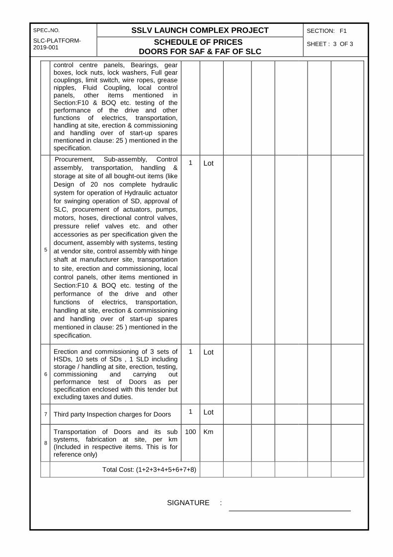
SPEC.NO. SSLV LAUNCH COMPLEX PROJECT SECTION: F1
SLC-PLATFORM-2019-001 SCHEDULE OF PRICES
DOORS FOR SAF & FAF OF SLC SHEET : 3 OF 3
control centre panels, Bearings, gear boxes, lock nuts, lock washers, Full gear couplings, limit switch, wire ropes, grease nipples, Fluid Coupling, local control panels, other items mentioned in Section:F10 & BOQ etc. testing of the performance of the drive and other functions of electrics, transportation, handling at site, erection & commissioning and handling over of start-up spares mentioned in clause: 25 ) mentioned in the specification.
5
Procurement, Sub-assembly, Control assembly, transportation, handling & storage at site of all bought-out items (like Design of 20 nos complete hydraulic system for operation of Hydraulic actuator for swinging operation of SD, approval of SLC, procurement of actuators, pumps, motors, hoses, directional control valves, pressure relief valves etc. and other accessories as per specification given the document, assembly with systems, testing at vendor site, control assembly with hinge shaft at manufacturer site, transportation to site, erection and commissioning, local control panels, other items mentioned in Section:F10 & BOQ etc. testing of the performance of the drive and other functions of electrics, transportation, handling at site, erection & commissioning and handling over of start-up spares mentioned in clause: 25 ) mentioned in the specification.
1 Lot
6
Erection and commissioning of 3 sets of HSDs, 10 sets of SDs , 1 SLD including storage / handling at site, erection, testing, commissioning and carrying out performance test of Doors as per specification enclosed with this tender but excluding taxes and duties.
1 Lot
7 Third party Inspection charges for Doors 1 Lot
8
Transportation of Doors and its sub systems, fabrication at site, per km (Included in respective items. This is for reference only)
100 Km
Total Cost: (1+2+3+4+5+6+7+8)
SIGNATURE :

SPEC.NO. SSLV LAUNCH COMPLEX PROJECT SECTION: F1
SLC-PLATFORM-2019-001 SCHEDULE OF PRICES
DOORS FOR SAF & FAF OF SLC SHEET : 4 OF 3
NAME :
DESIGNATION:
SEAL OF THE COMPANY DATE :

SPEC.NO. SSLV LAUNCH COMPLEX PROJECT SECTION: F2
SLC-DOOR-2019-001 BID QUALIFICATION CRITERIA DOORs FOR SAF & FAF OF SLC
SHEET : 1 OF 2
BID QUALIFICATION CRITERIA FOR SUPPLY OF DOORS
Bidders who are qualifying / meeting following Technical and financial criteria are eligible to participate in the bid for supply of Doors. Bidder shall furnish all the information mentioned in the criteria with documentary proof and submit along with quotation. Bids of the parties which are not meeting the following criteria will not be considered for evaluation and will be rejected without seeking any further clarifications.
A. Technical Qualification Requirements:
The bidder shall meet the following technical qualifying requirements and shall submit relevant certificates to establish his credentials.
1. The Bidder shall be an organization with 5 years of experience in having executed contracts for manufacture, supply, erection, testing and commissioning of heavy structural works using structural built-up sections.
2. The firm shall have successfully completed Manufacture, Installation, Testing and Commissioning of at least 320 t of structural work in single order or two structural work orders of 240 t each during last 5 years ending with 31.03.2019. Bidders have to provide relevant certificates from the Owners (end users) along with the submission of bid for consideration of bid document.
3. The firm shall have facilities for fabrication and handling big structural items of 12 m long and 9 m wide for fitment, alignment, welding etc.
4. The firm shall have facility for stress relieving and machining.
5. The firm should have successfully completed manufacture and establishment of heavy Structures to the satisfaction of reputed third party inspection agencies like M/s MECON, M/s M N Dastur, M/s Lloyds, M/s. DNV, M/s TCE.
B. Financial Qualification Requirements:
1. The Bidder should have annual turnover of more than a value of Rs. 1650 lakh on an average of the last three financial years ending with 31.03.2019.
2. The firm shall have successfully completed Manufacture, Installation, Testing and Commissioning of at least one structural work order of value Rs. 1100 lakh or two structural work orders of value Rs. 800 lakh each ,during last 5 years ending with 31.03.2019. Bidders have to provide relevant certificates from the Owners (end users) along with the submission of bid for consideration of bid document.
3. Current financial year Solvency certificate from a scheduled bank for Rs. 550 lakh or above.
C. Bid Selection Procedure and Process of Pre-Qualification
1. Short listing based on documents submitted, satisfying the all eligibility criteria given above by the firm or individual along with their Bid / application. (Non-submission of any document as given in above list within stipulated time leads to rejection of Bid).
2. Subsequently Bidder's competency, their technical achievements and financial status will be evaluated suitable for this project. Feedbacks from Bidder's clients will be verified.
3. Visit to sites by technical team (ISRO or Third party) where Bidder has established above mentioned works.
4. If required, visit will be made to their factory/ firm by technical team (ISRO or third

SPEC.NO. SSLV LAUNCH COMPLEX PROJECT SECTION: F2
SLC-DOOR-2019-001 BID QUALIFICATION CRITERIA DOORs FOR SAF & FAF OF SLC
SHEET : 2 OF 2
party) for accessing the capability of manufacturer. 5. Scrutiny of all technical specification and supply conditions mentioned in techno-
commercial bid. 6. Bids with partial offer (i.e. without complete scope) will not be considered for
evaluation.
D. Documents to be submitted along with the bid submission
1. Firm establishment certificate and nature of work.
2. Details of work similar type completed during the last 5 years ending with 31.03.2019.
(For SI. Nos. 2 & 5 of clause: A in sheet 1 of 2 in Section-F2)
3. Satisfactory work completion certificates from the clients, with the work order copies (for SI. Nos. 2 & 5 of clause: A in sheet 1 of 2 in Section-F2)
4. The Bidders PAN, GST Registration No.
5. The Bidders shall submit Profit & Loss Accounts, Balance Sheets duly certified by the auditor and IT returns for the last three financial years with acknowledgement from IT Department up to last 3 years, i.e FY 2015-16, FY 2016-17, FY 2017-18. Necessary documents shall be submitted.
6. IT/ TDS certificate shall be submitted for last three years, i.e FY 2015-16, FY 2016-17, FY 2017-18.
7. Structure and Organization chart of the company.
8. List of personnel with qualification & experience in the firm in the areas of design, production, quality, safety, administration etc., List of Machinery & Equipment’s to be used for the work

SPEC.NO. SSLV LAUNCH COMPLEX PROJECT SECTION: F3
SLC-DOOR-2019-001 SCHEDULE FOR GENERAL PARTICULARS
DOORS FOR SAF & SAF OF SLC
SHEET : 1 OF 3
SCHEDULE FOR GENERAL PARTICULARS / VENDOR EVALUATION FORMAT
SR. NO.
DESCRIPTION
1. Name of Company
2. Address of Company
3. Type of Company (Proprietary/Pvt.Ltd/Public Ltd/Joint Venure/Consortium)
4. Registration number
5. Year of inception of the company
6. Registered address
7. Name & address of the office of the Chief Executive of the company
8. Name & Designation of the officer of the Bidder to whom all correspondence shall be made for expeditious technical/ commercial co-ordination.
Telephone number Fax number E-mail address
9. Locations of the Branches of Company (if any)
10. Annual turn-over of the company for the last three years
11. IT returns for the last 3 years
12. Major customers (Enclose copies of the Purchase Orders)
13. Any customers feedback on the services which is in writing (Pl. enclose copies)
14. Quality certification of the company
15. PAN Card Copy
16. The Profit & Loss Account details for the last 3 years which is duly audited and Submitted as part of the Annual Report

SPEC.NO. SSLV LAUNCH COMPLEX PROJECT SECTION: F3
SLC-DOOR-2019-001 SCHEDULE FOR GENERAL PARTICULARS
DOORS FOR SAF & SAF OF SLC
SHEET : 2 OF 3
17. Orders executed during last three years, > 100 T or > Rs. 15 crores, references are is to be mentioned. (Separate sheet can be attached).
18. Shop floor area covered
19.
No. of employees (Supplier shall mention contract personnel separately) Engineers Supervisors Technicians Quality control engineers Administrative Staff.
20.
Handling facility available: Over head / Gantry Crane details (Capacity, span lift). Mobile Cranes.
21.
Load testing facility Available: Maximum weight available. No. of weights Total test load available.
22.
Welding / fabrication workshop (Type / capacity / quantity of machines shall be provided) MMAW machines GMAW machines Gas cutting machines Plasma cutting machines Welding Fixtures
23.
Welding professionals: No. of Welders (MMAW), Qualification details, No. of Welders (GMAW), Qualification details, No. of Welders (TIG), Qualification details, Welders Qualified by:
24. Details of welding Inspection Equipment & Welding inspector available with supplier (LPT, UT, MPT, X-ray, etc)
25.
Forming facilities available ( with brief specification of each machine) Shearing Machine Cutting Machine Cutting Machine Bending Machine
26.
Machining Facilities available ( with brief specification of each machine) Turning lathe (Conventional /CNC) Milling Machine (Conventional / CNC) Gear Cutting / Hobbing Machines Drilling Machines (conventional / CNC) Cylindrical Grinding Machine ( Conventional / CNC) Any other machines.
27. Details of inspection facilities / Instruments available ( Brief description & specifications shall be provided)

SPEC.NO. SSLV LAUNCH COMPLEX PROJECT SECTION: F3
SLC-DOOR-2019-001 SCHEDULE FOR GENERAL PARTICULARS
DOORS FOR SAF & SAF OF SLC
SHEET : 3 OF 3
28. If third party Inspection Services are taken for fabricating similar works give details.
29.
Design Software’s available Drafting & modeling software packages FEM software Other softwares Design Engineers ( with qualification & experience)
30. Bid validity period
(Min. 4 months from date of bid opening)
31. COMPLETION SCHEDULE
32. Period required for supply of equipment at site (from date of LOI)
___ months
33. Period required for erection, testing and commissioning (from date of LOI)
___ months
34. Distance is kilometres considered from supplier’s place to SDSC SHAR, Sriharikota for quoting transportation
charges (Sl No. 8) in price bid
SIGNATURE :
NAME :
DESIGNATION:
SEAL OF THE COMPANY DATE :

SPEC.NO. SSLV LAUNCH COMPLEX PROJECT SECTION: F4
SLC-DOOR-2019-001 CONFIRMATION OF ACHIEVING ACCURACY DOORS FOR SAF & FAF OF SLC
SHEET : 1 OF 1
CONFIRMATION OF ACHIEVING ACCURACY
The BIDDER shall furnish performance guarantees as listed below based on the data specified in section B:
1. Misalignment of Door leafs straightness from 0 m to 45m shall be limited to ± 2 mm. 2. Misalignment of Support brackets / interconnecting brackets with respect other
brackets shall be limited to ± 2 mm.
SIGNATURE :
NAME :
DESIGNATION:
SEAL OF THE COMPANY DATE :
ISSUE R0

SPEC.NO. SSLV LAUNCH COMPLEX PROJECT SECTION: F5
SLC-DOOR-2019-001 SCHEDULE OF DEVIATIONS FROM SPECIFICATIONS FOR DOORS FOR SAF & FAF OF SLC
SHEET : 1 OF 1
EXCEPTIONS AND DEVIATIONS
In line with Proposal Document, Bidder may stipulate Exceptions and deviations to the
proposed conditions if considered unavoidable.
Slno
Reference in
Specification Dept. Specification Offered Specification Deviation
Page no Clause no
NOTE :
Only deviations are to be written in the above form.
Any deviations taken by the Bidder to the stipulations of the Proposal document shall be
brought out strictly as per this format and enclosed along with the bid.
Any deviations not brought out in this Proforma and written elsewhere in the Proposal
document shall not be recognized and the same is treated as null and void.
Any willful attempt by the Bidders to camouflage the deviations by giving them in the
covering letter or in any other documents that are enclosed may render the Bid itself
non-responsive.
SIGNATURE :
NAME :
DESIGNATION:
SEAL OF THE COMPANY DATE :

SPEC.NO. SSLV LAUNCH COMPLEX PROJECT SECTION: F6
SLC-DOOR-2019-001 SCHEDULE OF TIME FOR MANUFACTURE, DESPATCH AND SHIPMENT TO SITE
DOORS FOR SAF & FAF OF SLC
SHEET : 1 OF 1
SCHEDULE OF TIME FOR MANUFACTURE, DESPATCH AND SHIPMENT TO SITE
The Bidder shall indicate hereunder the time for manufacture, despatch and
completion of each equipment from the date of Letter of Intent (LOI)/ purchase order
(PO) as shown below.
Equipment
Time for manufacture
from date of LOI / PO
excluding control
assembly
Time for packing and
ready for despatch from
Works
Time for
shipment to
site
Total time from
date of LOI / PO to
shipment to site.
The Bidder hereby undertakes to meet the above time schedule from the date of LOI
/ PO
SIGNATURE :
NAME :
DESIGNATION:
SEAL OF THE COMPANY DATE :

SP
EC
no:
S
LC-D
OO
R-2
019-
001
SS
LV
LA
UN
CH
CO
MP
LE
X P
RO
JEC
T
SE
CT
ION
: F7
DO
OR
S F
OR
SA
F &
FA
F O
F S
LC
S
HE
ET
: 1
OF
2
Shee
t 1
of 2
S
CH
ED
UL
E O
F B
IDD
ER
S E
XP
ER
IEN
CE
T
he b
idde
r sh
all f
urni
sh h
ere
unde
r a
list o
f ST
RU
CT
UR
AL
wor
ks e
xecu
ted
by h
im to
who
m a
ref
eren
ce m
ay b
e m
ade
by th
e P
UR
CH
AS
ER
in c
ase
the
PU
RC
HA
SE
R c
onsi
ders
suc
h a
refe
renc
e ne
cess
ary.
SL
. N
O.
Nam
e &
ad
dre
ss o
f C
lien
t /
Nam
e &
ad
dre
ss o
f p
roje
ct
or
pla
nt
(in
cl. t
el.n
o. f
ax
no
., e-
mai
l an
d n
ame
&
des
ign
atio
n o
f p
erso
n w
ho
ca
n b
e co
nta
cted
.
Pu
rch
ase
Ord
er /
Co
nta
ct n
o. a
nd
D
ate.
Bri
ef
det
ails
of
equ
ipm
ent
/ sys
tem
co
vere
d
Sco
pe
of
serv
ices
C
on
trac
t p
rice
(R
s)
Sch
edu
led
d
ate
of
com
ple
tio
n
Act
ual
dat
e o
f co
mp
leti
on
Rea
son
s fo
r d
elay
in
com
ple
tio
n,
if
app
licab
le.
RE
MA
RK
S
SIG
NA
TU
RE
: :
NA
ME
:
DE
SIG
NA
TIO
N:
CO
MP
AN
Y
: C
OM
PA
NY
SE
AL
D
AT
E
:

SP
EC
no:
S
LC-D
OO
R-2
019-
001
SS
LV
LA
UN
CH
CO
MP
LE
X P
RO
JEC
T
SE
CT
ION
: F7
DO
OR
S F
OR
SA
F &
FA
F O
F S
LC
S
HE
ET
: 2
OF
2
Shee
t 2
of 2
S
CH
ED
UL
E O
F B
IDD
ER
S P
RE
SE
NT
WO
RK
T
he b
idde
r sh
all f
urni
sh h
ere
unde
r a
list o
f Str
uctu
ral d
oors
bei
ng e
xecu
ted
to w
hom
a r
efer
ence
may
be
mad
e by
the
PU
RC
HA
SE
R in
ca
se th
e P
UR
CH
AS
ER
con
side
rs s
uch
a re
fere
nce
nece
ssar
y.
SL
. N
O.
Nam
e &
ad
dre
ss o
f C
lien
t /
Nam
e &
ad
dre
ss o
f p
roje
ct o
r p
lan
t (i
ncl
. tel
.no
. fax
no
., e-
mai
l an
d n
ame
& d
esig
nat
ion
of
per
son
wh
o c
an b
e co
nta
cted
.
Pu
rch
ase
Ord
er /
Co
nta
ct n
o. a
nd
D
ate.
Bri
ef d
etai
ls
of
equ
ipm
ent
/ sys
tem
co
vere
d
Sco
pe
of
serv
ices
C
on
trac
t p
rice
(R
s)
Sch
edu
led
d
ate
of
com
ple
tio
n
Exp
ecte
d
dat
e o
f co
mp
leti
on
R
EM
AR
KS
S
IGN
AT
UR
E:
NA
ME
:
DE
SIG
NA
TIO
N:
CO
MP
AN
Y
: C
ompa
ny S
eal
DA
TE
:
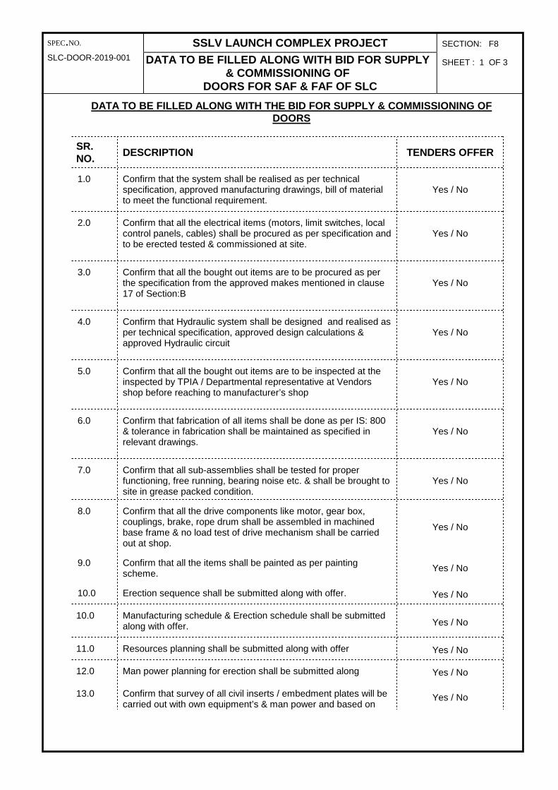
SPEC.NO. SSLV LAUNCH COMPLEX PROJECT SECTION: F8
SLC-DOOR-2019-001 DATA TO BE FILLED ALONG WITH BID FOR SUPPLY & COMMISSIONING OF
DOORS FOR SAF & FAF OF SLC
SHEET : 1 OF 3
DATA TO BE FILLED ALONG WITH THE BID FOR SUPPLY & COMMISSIONING OF DOORS
SR. NO.
DESCRIPTION TENDERS OFFER
1.0 Confirm that the system shall be realised as per technical specification, approved manufacturing drawings, bill of material to meet the functional requirement.
Yes / No
2.0 Confirm that all the electrical items (motors, limit switches, local control panels, cables) shall be procured as per specification and to be erected tested & commissioned at site.
Yes / No
3.0 Confirm that all the bought out items are to be procured as per the specification from the approved makes mentioned in clause 17 of Section:B
Yes / No
4.0 Confirm that Hydraulic system shall be designed and realised as per technical specification, approved design calculations & approved Hydraulic circuit
Yes / No
5.0 Confirm that all the bought out items are to be inspected at the inspected by TPIA / Departmental representative at Vendors shop before reaching to manufacturer’s shop
Yes / No
6.0 Confirm that fabrication of all items shall be done as per IS: 800 & tolerance in fabrication shall be maintained as specified in relevant drawings.
Yes / No
7.0 Confirm that all sub-assemblies shall be tested for proper functioning, free running, bearing noise etc. & shall be brought to site in grease packed condition.
Yes / No
8.0 Confirm that all the drive components like motor, gear box, couplings, brake, rope drum shall be assembled in machined base frame & no load test of drive mechanism shall be carried out at shop.
Yes / No
9.0 Confirm that all the items shall be painted as per painting scheme.
Yes / No
10.0 Erection sequence shall be submitted along with offer. Yes / No
10.0 Manufacturing schedule & Erection schedule shall be submitted along with offer. Yes / No
11.0 Resources planning shall be submitted along with offer Yes / No
12.0 Man power planning for erection shall be submitted along Yes / No
13.0 Confirm that survey of all civil inserts / embedment plates will be carried out with own equipment’s & man power and based on
Yes / No
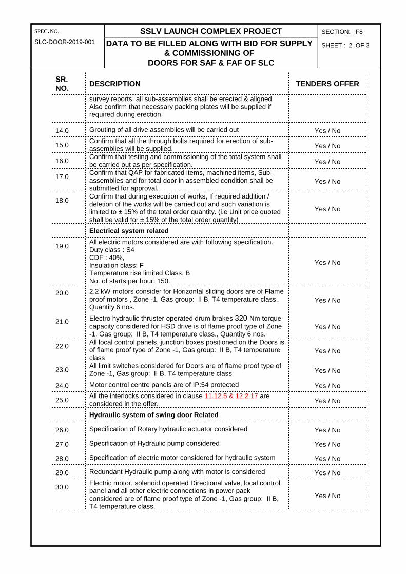
SPEC.NO. SSLV LAUNCH COMPLEX PROJECT SECTION: F8
SLC-DOOR-2019-001 DATA TO BE FILLED ALONG WITH BID FOR SUPPLY & COMMISSIONING OF
DOORS FOR SAF & FAF OF SLC
SHEET : 2 OF 3
SR. NO.
DESCRIPTION TENDERS OFFER
survey reports, all sub-assemblies shall be erected & aligned. Also confirm that necessary packing plates will be supplied if required during erection.
14.0 Grouting of all drive assemblies will be carried out Yes / No
15.0 Confirm that all the through bolts required for erection of sub-assemblies will be supplied. Yes / No
16.0 Confirm that testing and commissioning of the total system shall be carried out as per specification. Yes / No
17.0 Confirm that QAP for fabricated items, machined items, Sub-assemblies and for total door in assembled condition shall be submitted for approval.
Yes / No
18.0 Confirm that during execution of works, If required addition / deletion of the works will be carried out and such variation is limited to ± 15% of the total order quantity. (i.e Unit price quoted shall be valid for ± 15% of the total order quantity)
Yes / No
Electrical system related
19.0 All electric motors considered are with following specification. Duty class : S4 CDF : 40%, Insulation class: F Temperature rise limited Class: B No. of starts per hour: 150.
Yes / No
20.0 2.2 kW motors consider for Horizontal sliding doors are of Flame proof motors , Zone -1, Gas group: II B, T4 temperature class., Quantity 6 nos.
Yes / No
21.0 Electro hydraulic thruster operated drum brakes 320 Nm torque capacity considered for HSD drive is of flame proof type of Zone -1, Gas group: II B, T4 temperature class., Quantity 6 nos.
Yes / No
22.0 All local control panels, junction boxes positioned on the Doors is of flame proof type of Zone -1, Gas group: II B, T4 temperature class
Yes / No
23.0 All limit switches considered for Doors are of flame proof type of Zone -1, Gas group: II B, T4 temperature class Yes / No
24.0 Motor control centre panels are of IP:54 protected Yes / No
25.0 All the interlocks considered in clause 11.12.5 & 12.2.17 are considered in the offer. Yes / No
Hydraulic system of swing door Related
26.0 Specification of Rotary hydraulic actuator considered Yes / No
27.0 Specification of Hydraulic pump considered Yes / No
28.0 Specification of electric motor considered for hydraulic system Yes / No
29.0 Redundant Hydraulic pump along with motor is considered Yes / No
30.0 Electric motor, solenoid operated Directional valve, local control panel and all other electric connections in power pack considered are of flame proof type of Zone -1, Gas group: II B, T4 temperature class.
Yes / No

SPEC.NO. SSLV LAUNCH COMPLEX PROJECT SECTION: F8
SLC-DOOR-2019-001 DATA TO BE FILLED ALONG WITH BID FOR SUPPLY & COMMISSIONING OF
DOORS FOR SAF & FAF OF SLC
SHEET : 3 OF 3
SR. NO.
DESCRIPTION TENDERS OFFER
31.0 Please confirm that max operating pressure of the system is 200 bar Yes / No

SPEC.NO. SSLV LAUNCH COMPLEX PROJECT SECTION: F9
SLC-DOOR-2019-001 CHECK LIST FOR BID SUBMITTING OF DOORS FOR
SAF & FAF OF SLC
SHEET : 1 OF 2
CHECK LIST
Signature of the tenderer.
Sl no Description Response by supplier
1. All documents related to Prequalification criteria mention in Section F2 have been met and all related documents are enclosed in technical Bid
Yes / No
2. Are all the technical particulars as called for in the data sheets section A, B, C, D & E and commercial details as called for in schedule of prices filled up
Yes / No
3. Demand Draft towards the Tender fee and Earnest Money Deposit are enclosed in technical bid and scan copy is uploaded in e-procurement portal.
Yes / No
4. The detailed scope of work and technical specifications are understood and price was quoted accordingly.
Yes / No
5. Confirmation that the quoted prices are firm and fixed till the completion of scope of work.
Yes / No
6. Validity of Offer is 4 months (minimum). Yes / No
7. Vendor Evaluation Format is attached Yes / No
8. Customs Duty Exemption Certificate (CDEC) will be issued by Department for imported items mentioned in Section: A was considered in your offer or not.
Yes / No
9. Excise Duty Exemption Certificate (EDEC) will be issued by Department for finished product only. Hence, it is considered in you offer or not.
Yes / No
10. Service Tax 12.36 % or at the prevailing rates (If not mentioned it will be assumed that the price quoted are inclusive of taxes).
Yes / No
11. VAT/CST to be indicated in percentage (if not mentioned it will be assumed that the price quoted are inclusive of taxes).
Yes / No
12. Delivery Schedule with milestones Yes / No
13. Accepted the Department Payment Terms Yes / No
14. Are General terms and Conditions of Contract for Supply & Erection included in proposal acceptable?
Yes / No
15. If not acceptable, are the deviations brought out in the "Schedule of Deviations" Yes / No
16. Are there any deviations from enquiry technical specifications? Yes / No
17. If there are technical deviations, are these filled in "Schedule of Deviations from Tech. Specifications"?
Yes / No
18. Warranty for the fully commissioned and accepted system is 12 months Yes / No
19. 5 % of the Order Value shall be submitted as Performance Security for the performance of the contract along with acceptance of order letter, which is valid till acceptance of the system.
Yes / No
20. 10 % of the Order Value shall be submitted as Performance Bank Guarantee, which is valid till completion of the warranty period plus 3 months claim period.
Yes / No
21. Liquidated Damages (Ref. Clause 26 of Section A.) are acceptable Yes / No
22. Last three years audited financial results are enclosed Yes / No
23. Registration certificate of the company is enclosed Yes / No

SPEC.NO. SSLV LAUNCH COMPLEX PROJECT SECTION: F9
SLC-DOOR-2019-001 CHECK LIST FOR BID SUBMITTING OF DOORS FOR
SAF & FAF OF SLC
SHEET : 2 OF 2
CHECK LIST
Signature of the tenderer.
24. All the forms in Section F1 to F9 are filled Yes / No
25. Are all data sheets A/B duly filled in and submitted in offer Yes / No
26. Technical documents / drawings are attached along with technical bid as para 1.7.1 of Section A
Yes / No
27. Section F10 is filled and sealed cover is sent to SDSC SHAR for along with hard copy of technical bid.
Yes / No

SPEC.NO. SSLV LAUNCH COMPLEX PROJECT SECTION: F10
SLC-DOOR-2019-001 PRICE BREAK-UP DETAILS FOR BOUGHT-OUT ITEMS FOR DOORS FOR SAF & FAF OF SLC
SHEET : 1 OF 5
BREAK-UP IS TO BE GIVEN FOR SUPPLY COST OF THE BOUGHTOUT ITEMS
Sl.No.
Sl no. BOQ Specifications Unit Qty
required Unit Cost
Total cost
HSD
1 6.1
Flame proof motor: Zone -1, Gas group: II B, T4 temperature class. Power: 2.2 kW, Size: 132S,R.P.M : 750, A.C 3Ø,Duty class : S4,CDF : 40%, Insulation class: F Temperature rise limited Class: B No. of starts per hour : 150 Make: Kirloskar / Siemens
Nos. 6
2 6.2 Fluid Coupling Type: FCU – 14.5
3 6.4
Electro Hydraulic thruster brake Flame proof Zone -1, Gas group: II B, T4 temperature class, thrustor operated Drum brake, Max. Torque : 320 Nm
Nos. 6
4 6.5
Worm Gear Reducer Double stage worm gear box Reduction Ratio : 470:1 Output torque : 9330 Nm Input speed: 1.55 rpm Duty : Reversing Lubrication : Splash Bearing : Antifriction Self-locking type
Nos. 6
5 6.7 Coupling Type : Full Gear Coupling Allflex Type AFG106 Nos. 6
6 6.8 Coupling Type : Full Gear Coupling Allflex Type AFG102 Nos. 6
7 6.9 Wire Rope of Usha Martin make Powerform 8 with Tensile grade 2160 N/mm2, Ø 22 mm , 25 m length
Nos. 12
8 6.10
Limit Switches, Type: Multi angle roller lever operated, spring return type Protection Category: IP55 No. of contacts: 2 NO + 2 NC Rating: 240V AC, 5A Material: Aluminium alloy LM6 BALIGA type FLS 2115 or Equivalent
Nos. 12
9 6.11 Nitrile Rubber Sheet (Labyrinth Seal), 9000 (L) x 300 (W) x 50 (Thk.)
Nos. 12
10 6.12 Nitrile Rubber Sheet (Edge Seal Plate), 9000 (L) x 100 (W) x 50 (Thk.)
Nos. 12

SPEC.NO. SSLV LAUNCH COMPLEX PROJECT SECTION: F10
SLC-DOOR-2019-001 PRICE BREAK-UP DETAILS FOR BOUGHT-OUT ITEMS FOR DOORS FOR SAF & FAF OF SLC
SHEET : 2 OF 5
11 6.13 Nitrile Rubber Sheet (Bottom Seal Plate), 12000 (L) x 100 (W) x 15 (Thk.)
Nos. 12
12 6.18
Phenotherm board covered with aluminium sheet (200 micro thick), Size: 12000 (L) x 9000 (H)
Lot 6
13 6.19 Through Bolts / Foundation bolts for all Doors Kg 3000
14 Taper Roller Bearing of SKF 30217 T71 J2/QDB31 Nos. 24
15 Taper Roller Bearing of SKF 31318 T103 J2/DB31 Nos. 36
16 Deep Groove Ball Bearing – SKF 6218 2Z Nos. 240
17 Taper Roller Bearing of SKF Nos. 48
18
Spherical Roller Bearing, 95 ID x 170 OD x 43 width,
SKF # 22219 E or equivalent
Nos. 12
SD
19 Tapper Roller Bearing - 32030 x Nos 80
20
Hydraulic Rotary Actuator Double Rack & Foot Mounting Type Out Put Torque: 35 KNm, Operating Pressure: 207 bar, Hollow Shaft Size : 140 mm
Nos 20
21 Flame Proof Hydraulic Power Pac and Local Control for Individual Hydraulic Rotary Actuator
Nos 20
22
Limit Switches, Type: Multi angle roller lever operated, spring return type Protection Category: IP55 No. of contacts: 2 NO + 2 NC Rating: 240V AC, 5A Material: Aluminium alloy LM6 BALIGA type FLS 2115 or Equivalent
Nos. 40
23 Nitrile Rubber Sheet (Labyrinth Seal), 9000 (L) x 300 (W) x 50 (Thk.)
Nos. 40
24 Nitrile Rubber Sheet (Edge Seal Plate), 9000 (L) x 100 (W) x 50 (Thk.)
Nos. 40
25 Nitrile Rubber Sheet (Bottom Seal Plate), 2000 (L) x 100 (W) x 15 (Thk.)
Nos. 40
26 Phenotherm board covered with aluminium sheet (200 micro thick), Size: 2000 (L) x 9000 (H)
Lot 20
SLD
27
Flame Proof Geared Motor Make: PBL or Equivalent Power: 0.75 KW Input Speed: 1000 RPM Output Speed: 2.11 RPM
Nos. 1

SPEC.NO. SSLV LAUNCH COMPLEX PROJECT SECTION: F10
SLC-DOOR-2019-001 PRICE BREAK-UP DETAILS FOR BOUGHT-OUT ITEMS FOR DOORS FOR SAF & FAF OF SLC
SHEET : 3 OF 5
Output Torque: 3222 Nm Reduction Ratio: 435
28
Limit Switches, Type: Multi angle roller lever operated, spring return type Protection Category: IP55 No. of contacts: 2 NO + 2 NC Rating: 240V AC, 5A Material: Aluminium alloy LM6 BALIGA type FLS 2115 or Equivalent
Nos. 2
29 Nitrile Rubber Sheet (Labyrinth Seal), 9000 (L) x 300 (W) x 50 (Thk.)
Nos. 2
30 Nitrile Rubber Sheet (Edge Seal Plate), 9000 (L) x 100 (W) x 50 (Thk.)
Nos. 2
31 Nitrile Rubber Sheet (Bottom Seal Plate), 12000 (L) x 100 (W) x 15 (Thk.)
Nos. 2
32 Phenotherm board covered with aluminium sheet (200 micro thick), Size: 12000 (L) x 9000 (H)
Lot 1
The quantity required given is tentative only it vary with respect to final fabrication drawings.