“Annex H Inspection and Test Protocol
93
Mass production and Supply of Science and Mathematics Equipment packages to Public Elementary Schools for Grades 1 to 3 & Grade 4 to 6, Public Junior High School for Grades 7 to 10 and Public Senior High Schools for Grades 11 to 12 (Core and Stem) 1 | Page “Annex H” Inspection and Test Protocol To ensure conformance to the Technical Specifications, all items under contract shall undergo the thorough inspection process and procedure during the evaluation or pre-delivery inspection. In predelivery inspection both specifications and approved samples shall serve as the references however, if discrepancies arise between specifications and approved sample, the approved sample shall prevail. During the predelivery inspection, the sampling plan to be adapted will be the prescribed threshold of 10% as specified in the COA Training Handbook on Property and Supply Management System (Technique in Property Inspection) for all goods except electrical items which will be subjected to 100% inspection as specified in Annex F of the bidding documents. A. General Inspection Protocol. This general protocol shall serve as guide in the conduct of the Evaluation Samples/predelivery inspection for all market items (where the following statement is applicable). a.) verify/evaluate the parameters of the goods or product as indicated in the specifications e.g. material, dimensions, capacity, power rating, etc.; b.) check the goods for any evidence of defects visually as follows: i) rust formation ii) cracked/broken parts iii) warps/dents iv) loose parts v) discoloration c.) look into the completeness of parts/accessories; d.) all goods powered by dry cell (AA, AAA, etc.) shall be included with corresponding batteries ready for use; e.) the bidder shall unbox, set up (if applicable), and manipulate the goods to be evaluated and shall perform corresponding performance and/or functionality tests. f.) Resistor Tolerance. The resistor shall be ±10%, unless otherwise specified. g.) Linear Tolerance. The DIN ISO 2768 (General Tolerances) very coarse under linear, external radius and chamfer heights and angular dimensions shall be applied, unless otherwise specified. h.) Markings and Labels shall be in English, with correct spelling, permanent (pass the 3M 610 Tape Test) i.) Refer to the key card to identify the structures. j.) The bidder/supplier shall provide the materials and consumables. ITEM NO. ITEM DESCRIPTION INSPECTION and TEST PROCEDURES I. MASS PRODUCTION ITEMS LOT 1: BLR-DEVELOPED BASIC SCIKIT
Transcript of “Annex H Inspection and Test Protocol

Mass production and Supply of Science and Mathematics Equipment packages to Public Elementary Schools for Grades 1 to 3 & Grade 4 to 6, Public Junior High School for Grades 7 to 10 and Public Senior
High Schools for Grades 11 to 12 (Core and Stem)
1 | P a g e
“Annex H”
Inspection and Test Protocol
To ensure conformance to the Technical Specifications, all items under contract shall undergo
the thorough inspection process and procedure during the evaluation or pre-delivery
inspection. In predelivery inspection both specifications and approved samples shall serve as
the references however, if discrepancies arise between specifications and approved sample,
the approved sample shall prevail.
During the predelivery inspection, the sampling plan to be adapted will be the
prescribed threshold of 10% as specified in the COA Training Handbook on Property
and Supply Management System (Technique in Property Inspection) for all goods except
electrical items which will be subjected to 100% inspection as specified in Annex F of
the bidding documents.
A. General Inspection Protocol. This general protocol shall serve as guide in the conduct
of the Evaluation Samples/predelivery inspection for all market items (where the
following statement is applicable).
a.) verify/evaluate the parameters of the goods or product as indicated in the specifications
e.g. material, dimensions, capacity, power rating, etc.;
b.) check the goods for any evidence of defects visually as follows:
i) rust formation
ii) cracked/broken parts
iii) warps/dents
iv) loose parts
v) discoloration
c.) look into the completeness of parts/accessories;
d.) all goods powered by dry cell (AA, AAA, etc.) shall be included with corresponding batteries
ready for use;
e.) the bidder shall unbox, set up (if applicable), and manipulate the goods to be evaluated
and shall perform corresponding performance and/or functionality tests.
f.) Resistor Tolerance. The resistor shall be ±10%, unless otherwise specified.
g.) Linear Tolerance. The DIN ISO 2768 (General Tolerances) very coarse under linear,
external radius and chamfer heights and angular dimensions shall be applied, unless
otherwise specified.
h.) Markings and Labels shall be in English, with correct spelling, permanent (pass the 3M
610 Tape Test)
i.) Refer to the key card to identify the structures.
j.) The bidder/supplier shall provide the materials and consumables.
ITEM NO. ITEM DESCRIPTION
INSPECTION and TEST PROCEDURES
I. MASS PRODUCTION ITEMS
LOT 1: BLR-DEVELOPED BASIC SCIKIT

2 | P a g e
1
BLR-developed Basic Scikit: Ø 9.5mm x 250mm long
Stand Rod
(a) In the evaluation of sample, the technical specifications, as part of the Contract, will be used as reference. However, in the pre-delivery
inspection, it will be the approved sample that will be used as reference. (b) There must be no sharp edges, cracks, scratches, and other deficiencies/defects on the item.
(c) Do dimensional inspection. Measure the diameter and length of the rod. (d) Do material evaluation. (e) Check the straightness of the rod taking into consideration the
maximum allowable linear deflection as specified in the technical specifications. (f) Inspect the surface finish. (g) Check the radius of the rounded ends of the rod.
(h) Do functionality test to validate the level of performance and accuracy of the rod especially when used as component of the Stand Setup.
2
BLR-developed Basic Scikit: Ø 9.5mm x 500mm long Stand Rod
(a) In the evaluation of sample, the technical specifications, as part of the Contract, will be used as reference. However, in the pre-delivery inspection, it will be the approved sample that will be used as reference.
(b) There must be no sharp edges, cracks, scratches, and other deficiencies/defects on the item. (c) Do dimensional inspection. Measure the diameter and length of the rod.
(d) Do material evaluation. (e) Check the straightness of the rod taking into consideration the maximum allowable linear deflection as specified in the technical specifications.
(f) Inspect the surface finish. (g) Check the radius of the rounded ends of the rod. (h) Do functionality test to validate the level of performance and
accuracy of the rod especially when used as component of the Stand Setup.
3
BLR-developed Basic Scikit: Ø 12.7mm x 1000mm long
Stand Rod
(a) In the evaluation of sample, the technical specifications, as part of the Contract, will be used as reference. However, in the pre-delivery
inspection, it will be the approved sample that will be used as reference. (b) There must be no sharp edges, cracks, scratches, and other deficiencies/defects on the item.
(c) Do dimensional inspection. Measure the diameter and length of the rod. (d) Do material evaluation. (e) Check the straightness of the rod taking into consideration the
maximum allowable linear deflection as specified in the technical specifications. (f) Inspect the surface finish. (g) Check the radius of the rounded ends of the rod.
(h) Do functionality test to validate the level of performance and accuracy of the rod especially when used as component of the Stand Setup.
4
BLR-developed Basic Scikit: Rail
(a) In the evaluation of sample, the technical specifications, as part of the Contract, will be used as reference. However, in the pre-delivery inspection, it will be the approved sample that will be used as reference.
(b) Do dimensional inspection. Measure the diameters and length of the rail. (c) Do material evaluation. (d) Check the straightness of the rail.
(e) Inspect the surface finish. (f) Check the radius of the rounded ends of the rail. (g) Do functionality test to validate the level of performance and accuracy of the rail especially when used as component in the Cart-
Rail System.

3 | P a g e
5
BLR-developed Basic Scikit: Ring with stem
(a) In the evaluation of sample, the technical specifications, as part of the Contract, will be used as reference. However, in the pre-delivery
inspection, it will be the approved sample that will be used as reference. (b) There must be no sharp edges, cracks, scratches, and other deficiencies/defects on the item.
(c) Do dimensional inspection. Measure the length, rod diameter, and ring diameter of the item. (d) Do material evaluation. (e) Inspect the surface finish.
(f) Do functionality test to validate the level of performance of the item especially when used as component of the Stand Setup.
6
BLR-developed Basic Scikit:
Test Tube Rack
(a) In the evaluation of sample, the technical specifications, as part of
the Contract, will be used as reference. However, in the pre-delivery inspection, it will be the approved sample that will be used as reference. (b) To determine the conformity of the plastic materials to the
technical specifications, the materials should be tested by DOST material testing facilities or at any DOST-accredited testing institution. Test certificate/s should be issued by the testing unit, the original copy should be submitted to BLR-Cebu to validate the
specified materials. A representative of the Procuring Entity should be present during preparation and submission of the material test specimens to testing facility. All expenses for the said test shall be shouldered by the Supplier.
(c) Do material evaluation of the non-plastic parts. On the Individual Parts: (d) Do dimensional inspection of the individual parts. Measure lengths, widths, depths, diameters, holes, distances between holes,
threads, etc. (e) Inspect the surface finish of individual parts. Material colors specified in the technical specifications must be followed.
(f) There must be no breakage, chipped edges, sharp edges, cracks, scratches, warping, and other deficiencies/defects on the individual parts. On the Assembly:
(g) Check the horizontality and verticality of the test tube rack when this is laid flat on a horizontally-level table surface. (h) Do functionality test to validate the level of performance of the Test Tube Rack.
7
BLR-developed Basic Scikit: Wire Gauze
(a) In the evaluation of sample, the technical specifications, as part of the Contract, will be used as reference. However, in the pre-delivery inspection, it will be the approved sample that will be used as reference.
(b) Do dimensional inspection. Measure the length, width, wire diameter, and mesh per inch of the item. (c) Do material evaluation. (d) Inspect the jackets and their thickness.
(e) See to it that the jackets are properly welded on the four (4) corners of the item. (f) Do functionality test to validate the level of performance of the item
especially when used as component of the Stand Setup.
4 | P a g e
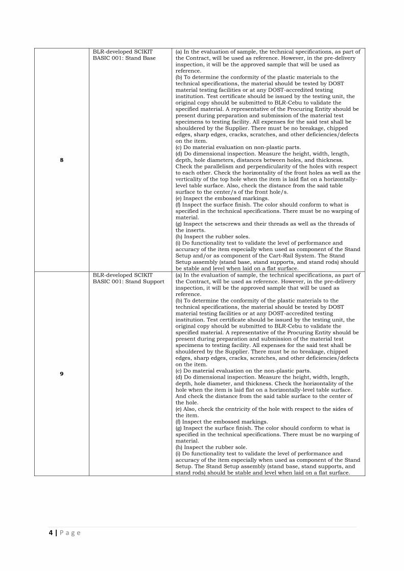
8
BLR-developed SCIKIT BASIC 001: Stand Base
(a) In the evaluation of sample, the technical specifications, as part of the Contract, will be used as reference. However, in the pre-delivery
inspection, it will be the approved sample that will be used as reference. (b) To determine the conformity of the plastic materials to the technical specifications, the material should be tested by DOST
material testing facilities or at any DOST-accredited testing institution. Test certificate should be issued by the testing unit, the original copy should be submitted to BLR-Cebu to validate the specified material. A representative of the Procuring Entity should be
present during preparation and submission of the material test specimens to testing facility. All expenses for the said test shall be shouldered by the Supplier. There must be no breakage, chipped edges, sharp edges, cracks, scratches, and other deficiencies/defects
on the item. (c) Do material evaluation on non-plastic parts. (d) Do dimensional inspection. Measure the height, width, length,
depth, hole diameters, distances between holes, and thickness. Check the parallelism and perpendicularity of the holes with respect to each other. Check the horizontality of the front holes as well as the verticality of the top hole when the item is laid flat on a horizontally-
level table surface. Also, check the distance from the said table surface to the center/s of the front hole/s. (e) Inspect the embossed markings. (f) Inspect the surface finish. The color should conform to what is
specified in the technical specifications. There must be no warping of material. (g) Inspect the setscrews and their threads as well as the threads of the inserts.
(h) Inspect the rubber soles. (i) Do functionality test to validate the level of performance and accuracy of the item especially when used as component of the Stand Setup and/or as component of the Cart-Rail System. The Stand
Setup assembly (stand base, stand supports, and stand rods) should be stable and level when laid on a flat surface.
9
BLR-developed SCIKIT
BASIC 001: Stand Support
(a) In the evaluation of sample, the technical specifications, as part of
the Contract, will be used as reference. However, in the pre-delivery inspection, it will be the approved sample that will be used as reference. (b) To determine the conformity of the plastic materials to the
technical specifications, the material should be tested by DOST material testing facilities or at any DOST-accredited testing institution. Test certificate should be issued by the testing unit, the original copy should be submitted to BLR-Cebu to validate the
specified material. A representative of the Procuring Entity should be present during preparation and submission of the material test specimens to testing facility. All expenses for the said test shall be shouldered by the Supplier. There must be no breakage, chipped
edges, sharp edges, cracks, scratches, and other deficiencies/defects on the item. (c) Do material evaluation on the non-plastic parts. (d) Do dimensional inspection. Measure the height, width, length,
depth, hole diameter, and thickness. Check the horizontality of the hole when the item is laid flat on a horizontally-level table surface. And check the distance from the said table surface to the center of the hole.
(e) Also, check the centricity of the hole with respect to the sides of the item. (f) Inspect the embossed markings. (g) Inspect the surface finish. The color should conform to what is
specified in the technical specifications. There must be no warping of material. (h) Inspect the rubber sole. (i) Do functionality test to validate the level of performance and
accuracy of the item especially when used as component of the Stand Setup. The Stand Setup assembly (stand base, stand supports, and stand rods) should be stable and level when laid on a flat surface.

5 | P a g e
10
BLR-developed SCIKIT BASIC 001: SCIKIT BASIC
Storage Case 001 (With Cover and Base Sheathing)
(a) In the evaluation of sample, the technical specifications, as part of the Contract, will be used as reference. However, in the pre-delivery
inspection, it will be the approved sample that will be used as reference. (b) To determine the conformity of the plastic material to the technical specifications, the material should be tested by DOST
material testing facilities or at any DOST-accredited testing institution. Test certificate should be issued by the testing unit, the original copy should be submitted to BLR-Cebu to validate the specified material. A representative of the Procuring Entity should be
present during preparation and submission of the material test specimen to testing facility. All expenses for the said test shall be shouldered by the Supplier. There must be no breakage, chipped edges, sharp edges, cracks, scratches, warping, and other
deficiencies/defects on the item. (c) Do dimensional inspection. Measure lengths, widths, thicknesses, diameters, radii, depths, draft angles, etc.
(d) Check the surface finish. The color of the material should conform to what is specified in the technical specifications. Note: There must be no warping and/or twisting of material. (e) Check the perpendicularity and parallelism of the sides/walls with
respect to each other. (f) Check the printed markings. (g) Using a spirit level, check the horizontality of the case when this is laid flat on a horizontally-level table surface.
(h) Check the cover. There must be no warping and/or twisting of the cover. (i) Check the base sheathing and its fixation on the case. (j) Do functionality test to validate the storage case’s level of
performance and accuracy by loading the specific science equipment intended for it to store.
11
BLR-developed SCIKIT
BASIC 002: Multiclamp
(a) In the evaluation of sample, the technical specifications, as part of
the Contract, will be used as reference. However, in the pre-delivery inspection, it will be the approved sample that will be used as reference. (b) To determine the conformity of the Aluminum-Silicon-Copper
Alloy material to the technical specifications, the material should be tested by DOST material testing facilities or at any DOST-accredited testing institution. Test certificate should be issued by the testing unit, the original copy should be submitted to BLR-Cebu to validate
the specified material. A representative of the Procuring Entity should be present during preparation and submission of the material test specimens to testing facility. All expenses for the said test shall be shouldered by the Supplier. There must be no breakage, chipped
edges, sharp edges, cracks, scratches, and other deficiencies/defects on the item. (c) Do material evaluation on the non-zinc alloy parts. (d) Do dimensional inspection. Measure the height, width, length,
depth, hole diameters, and thickness. Check the parallelism and perpendicularity of the sides with respect to each other. (e) Inspect the embossed markings. (f) Check the holes and their threads as well as their alignment to the
V-cuts situated opposite them. Also, check the perpendicularity of the said holes with respect to the surfaces on which they were drilled. (g) Inspect the surface finish. (h) Inspect the setscrews and their threads.
(i) Do functionality test to validate the level of performance and accuracy of the item especially when used as component of the Stand Setup. (Note: Special attention shall be given to the perpendicularity and parallelism of the assembled parts of the Stand Setup.)
12
BLR-developed SCIKIT BASIC 002: Test Tube Holder
(a) In the evaluation of sample, the technical specifications, as part of the Contract, will be used as reference. However, in the pre-delivery inspection, it will be the approved sample that will be used as
reference. (b) There must be no sharp edges, cracks, scratches, and other deficiencies/defects on the item. (c) Do dimensional inspection. Measure the length, width, and wire
diameter. (d) Do material evaluation. (e) Inspect the surface finish. (f) Do functionality test to validate the level of performance of the
item. Test the item by picking up and holding a Ǿ16mm test tube full of sand. Check the grip if it is evenly applied on the surface of the
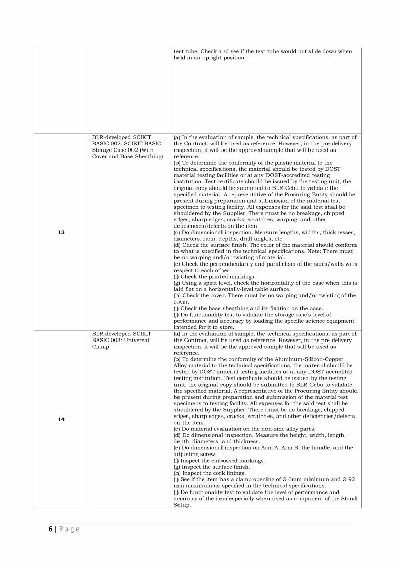
6 | P a g e
test tube. Check and see if the test tube would not slide down when held in an upright position.
13
BLR-developed SCIKIT BASIC 002: SCIKIT BASIC Storage Case 002 (With Cover and Base Sheathing)
(a) In the evaluation of sample, the technical specifications, as part of the Contract, will be used as reference. However, in the pre-delivery inspection, it will be the approved sample that will be used as reference.
(b) To determine the conformity of the plastic material to the technical specifications, the material should be tested by DOST material testing facilities or at any DOST-accredited testing institution. Test certificate should be issued by the testing unit, the
original copy should be submitted to BLR-Cebu to validate the specified material. A representative of the Procuring Entity should be present during preparation and submission of the material test specimen to testing facility. All expenses for the said test shall be
shouldered by the Supplier. There must be no breakage, chipped edges, sharp edges, cracks, scratches, warping, and other deficiencies/defects on the item. (c) Do dimensional inspection. Measure lengths, widths, thicknesses,
diameters, radii, depths, draft angles, etc. (d) Check the surface finish. The color of the material should conform to what is specified in the technical specifications. Note: There must be no warping and/or twisting of material.
(e) Check the perpendicularity and parallelism of the sides/walls with respect to each other. (f) Check the printed markings. (g) Using a spirit level, check the horizontality of the case when this is
laid flat on a horizontally-level table surface. (h) Check the cover. There must be no warping and/or twisting of the cover. (i) Check the base sheathing and its fixation on the case.
(j) Do functionality test to validate the storage case’s level of performance and accuracy by loading the specific science equipment intended for it to store.
14
BLR-developed SCIKIT BASIC 003: Universal Clamp
(a) In the evaluation of sample, the technical specifications, as part of the Contract, will be used as reference. However, in the pre-delivery inspection, it will be the approved sample that will be used as reference.
(b) To determine the conformity of the Aluminum-Silicon-Copper Alloy material to the technical specifications, the material should be tested by DOST material testing facilities or at any DOST-accredited testing institution. Test certificate should be issued by the testing
unit, the original copy should be submitted to BLR-Cebu to validate the specified material. A representative of the Procuring Entity should be present during preparation and submission of the material test specimens to testing facility. All expenses for the said test shall be
shouldered by the Supplier. There must be no breakage, chipped edges, sharp edges, cracks, scratches, and other deficiencies/defects on the item. (c) Do material evaluation on the non-zinc alloy parts.
(d) Do dimensional inspection. Measure the height, width, length, depth, diameters, and thickness. (e) Do dimensional inspection on Arm A, Arm B, the handle, and the adjusting screw.
(f) Inspect the embossed markings. (g) Inspect the surface finish. (h) Inspect the cork linings. (i) See if the item has a clamp opening of Ø 6mm minimum and Ø 92
mm maximum as specified in the technical specifications. (j) Do functionality test to validate the level of performance and accuracy of the item especially when used as component of the Stand Setup.
7 | P a g e
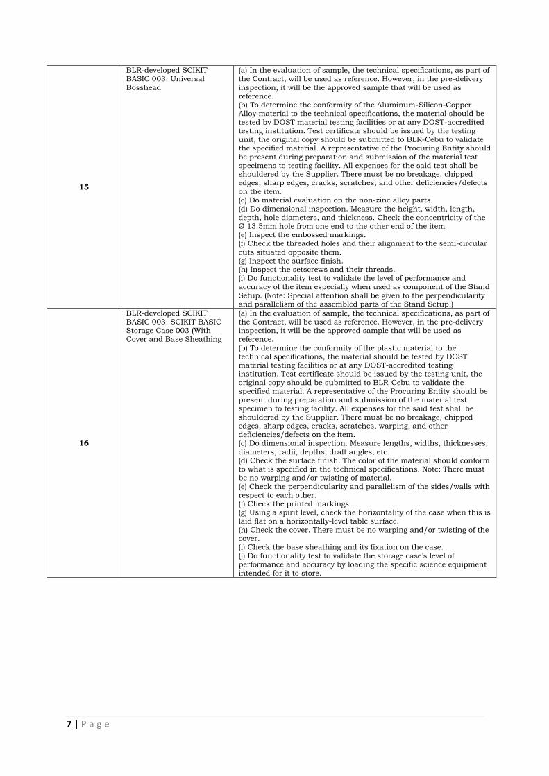
15
BLR-developed SCIKIT BASIC 003: Universal
Bosshead
(a) In the evaluation of sample, the technical specifications, as part of the Contract, will be used as reference. However, in the pre-delivery
inspection, it will be the approved sample that will be used as reference. (b) To determine the conformity of the Aluminum-Silicon-Copper Alloy material to the technical specifications, the material should be
tested by DOST material testing facilities or at any DOST-accredited testing institution. Test certificate should be issued by the testing unit, the original copy should be submitted to BLR-Cebu to validate the specified material. A representative of the Procuring Entity should
be present during preparation and submission of the material test specimens to testing facility. All expenses for the said test shall be shouldered by the Supplier. There must be no breakage, chipped edges, sharp edges, cracks, scratches, and other deficiencies/defects
on the item. (c) Do material evaluation on the non-zinc alloy parts. (d) Do dimensional inspection. Measure the height, width, length,
depth, hole diameters, and thickness. Check the concentricity of the Ø 13.5mm hole from one end to the other end of the item (e) Inspect the embossed markings. (f) Check the threaded holes and their alignment to the semi-circular
cuts situated opposite them. (g) Inspect the surface finish. (h) Inspect the setscrews and their threads. (i) Do functionality test to validate the level of performance and
accuracy of the item especially when used as component of the Stand Setup. (Note: Special attention shall be given to the perpendicularity and parallelism of the assembled parts of the Stand Setup.)
16
BLR-developed SCIKIT
BASIC 003: SCIKIT BASIC Storage Case 003 (With Cover and Base Sheathing
(a) In the evaluation of sample, the technical specifications, as part of
the Contract, will be used as reference. However, in the pre-delivery inspection, it will be the approved sample that will be used as reference.
(b) To determine the conformity of the plastic material to the technical specifications, the material should be tested by DOST material testing facilities or at any DOST-accredited testing institution. Test certificate should be issued by the testing unit, the
original copy should be submitted to BLR-Cebu to validate the specified material. A representative of the Procuring Entity should be present during preparation and submission of the material test specimen to testing facility. All expenses for the said test shall be
shouldered by the Supplier. There must be no breakage, chipped edges, sharp edges, cracks, scratches, warping, and other deficiencies/defects on the item. (c) Do dimensional inspection. Measure lengths, widths, thicknesses,
diameters, radii, depths, draft angles, etc. (d) Check the surface finish. The color of the material should conform to what is specified in the technical specifications. Note: There must be no warping and/or twisting of material.
(e) Check the perpendicularity and parallelism of the sides/walls with respect to each other. (f) Check the printed markings. (g) Using a spirit level, check the horizontality of the case when this is
laid flat on a horizontally-level table surface. (h) Check the cover. There must be no warping and/or twisting of the cover. (i) Check the base sheathing and its fixation on the case.
(j) Do functionality test to validate the storage case’s level of performance and accuracy by loading the specific science equipment intended for it to store.

8 | P a g e
17
BLR-developed Free Fall Apparatus (Mechanics 001):
Ball Case (with Cover and foam)
(a) In the evaluation of sample, the technical specifications, as part of the Contract, will be used as reference. However, in the pre-delivery
inspection, it will be the approved sample that will be used as reference. (b) To determine the conformity of the plastic material to the technical specifications, a certificate from DOST, which would attest
to the said conformity, is required for the Supplier to submit. (Note: A representative of the Procuring Entity should be present during preparation and submission of the material test specimen to DOST. All expenses for the said test shall be shouldered by the Supplier.)
There must be no sharp edges, cracks, scratches, warping, chipped edges, breakage, and other deficiencies/defects on the item. (c) Do dimensional inspection of the Case and its Cover. Measure lengths, widths, thicknesses, diameters, radii, depths, draft angles,
etc. (d) Check the surface finish. The color of the material should conform to what is specified in the technical specifications. There must be no
warping of material. (e) Check the DepED-BLR embossed markers (on the Case and Cover). (f) Check the cushion (soft foam). Measure length, width, and
thickness. (g) Do functionality test to validate its level of performance and accuracy by loading the spherical balls intended for it to store.
18
BLR-developed Free Fall
Apparatus (Mechanics 001): Digital Timer Assembly (Digital Stopwatch)
(a) In the evaluation of sample, the technical specifications, as part of
the Contract, will be used as reference. However, in the pre-delivery inspection, it will be the approved sample that will be used as reference. (b) Do dimensional inspection of the electronic digital stopwatch and
the female electronic jack (RCA jack). (c) There must be no breakage, chipped edges, sharp edges, cracks, scratches, and other deficiencies on the assembly.
(d) Open the back cover of the stopwatch and using the Schematic Wiring Diagram as reference, inspect how the wiring (inside the stopwatch) is done. Check, also, the type (or kind) of wire used. (e) Do functionality test to validate the level of performance and
accuracy of the Digital Timer Assembly by using it as component of the Free-Fall Apparatus in conducting experiment on free fall.
19
BLR-developed Free Fall Apparatus (Mechanics 001):
Metertape with hooks and plastic pointer
METERTAPE (a) In the evaluation of sample, the technical specifications, as part of
the Contract, will be used as reference. However, in the pre-delivery inspection, it will be the approved sample that will be used as reference. (b) There must be no sharp edges, chipped edges, cracks, scratches,
and other deficiencies/defects on the item. (c) Do dimensional inspection. Measure the lengths, widths, thicknesses, diameters, radii, etc. (d) Inspect the meter tape (or measuring tape). Check the printed
numerals, graduations, and printed letters. Inspect the plastic case. (Note: The meter tape should be able to measure in Metric and English units.) Check the accuracy of measurements. Check the
maximum measuring capacity of the meter tape. (e) Inspect Hook A and Hook B and their fixations on the meter tape. (f) Inspect the surface finish. (g) Do functionality test to validate the level of performance and
accuracy of the Meter Tape with hooks Assembly especially when used as component of the Free-Fall Apparatus in conducting experiment on free fall. POINTER
(a) In the evaluation of sample, the technical specifications, as part of the Contract, will be used as reference. However, in the pre-delivery inspection, it will be the approved sample that will be used as reference.
(b) To determine the conformity of the plastic material to the technical specifications, a certificate from DOST, which would attest to the said conformity, is required for the Supplier to submit. (Note: A representative of the Procuring Entity should be present during
preparation and submission of the material test specimen to DOST. All expenses for the said test shall be shouldered by the Supplier.) There must be no sharp edges, cracks, scratches, warping, chipped edges, breakage, and other deficiencies/defects on the item.
(a) Do dimensional inspection. Measure the length, width, height, thicknesses, radii, angles, etc. (c) Inspect the surface finish. The color of the material should

9 | P a g e
conform to what is specified in the technical specifications. (b) Do functionality test to validate the level of performance and
accuracy of the Pointer especially when used as component of the Free-Fall Apparatus in conducting experiment on free fall.
20
BLR-developed Free Fall
Apparatus (Mechanics 001): Ǿ 12.7mm Steel Spherical Ball
(a) In the evaluation of sample, the technical specifications, as part of
the Contract, will be used as reference. However, in the pre-delivery inspection, it will be the approved sample that will be used as reference. (b) There must be no cracks, scratches, dents, and other
deficiencies/defects on the item. (c) Do dimensional inspection. Measure the diameter of the chrome-plated steel ball. (d) Check the weight. The weight should conform to what is specified
in the technical specifications. (e) Inspect the surface finish. (f) Test the level of performance by using it as component of the Free-Fall Apparatus in conducting experiment on free fall.
21
BLR-developed Free Fall Apparatus (Mechanics 001): Ǿ 25mm Plastic Spherical
Ball with metal screw
(a) In the evaluation of sample, the technical specifications, as part of the Contract, will be used as reference. However, in the pre-delivery inspection, it will be the approved sample that will be used as
reference. (b) There must be no cracks, scratches, dents, and other deficiencies/defects on the item. (c) Do dimensional inspection. Measure the diameter of the plastic
ball as well as the diameter of the hole intended for the steel screw. (d) Inspect the steel screw. It must be new and rust-free. (e) Inspect the surface finish. The color of the plastic ball should conform to what is specified in the technical specifications.
(f) Check the weight (of the plastic ball with screw). The weight should conform to what is specified in the technical specifications. (g) Test the level of performance by using it as component of the Free-Fall Apparatus in conducting experiment on free fall.
22
BLR-developed Free Fall Apparatus (Mechanics 001): Ǿ 25mm Steel Spherical
Ball
(a) In the evaluation of sample, the technical specifications, as part of the Contract, will be used as reference. However, in the pre-delivery inspection, it will be the approved sample that will be used as
reference. (b) There must be no cracks, scratches, dents, and other deficiencies/defects on the item. (c) Do dimensional inspection. Measure the diameter of the chrome-
plated steel ball. (d) Check the weight. The weight should conform to what is specified in the technical specifications. (e) Inspect the surface finish.
(f) Test the level of performance by using it as component of the Free-Fall Apparatus in conducting experiment on free fall.
10 | P a g e
23
BLR-developed Free Fall Apparatus (Mechanics 001):
Pad Switch Assembly
a. In the evaluation of sample, the technical specifications, as part of the Contract, will be used as reference. However, in the pre-delivery
inspection, it will be the approved sample that will be used as reference. b. To determine the conformity of the plastic material to the technical specifications, a certificate from DOST, which would attest to the said
conformity, is required for the Supplier to submit. (Note: A representative of the Procuring Entity should be present during preparation and submission of the material test specimen to DOST. All expenses for the said test shall be shouldered by the Supplier.)
On the Individual Parts: (a) Do dimensional inspection of the individual parts. Measure lengths, widths, depths, diameters, holes, distances between holes, threads, etc.
(b) Inspect the surface finish of the individual parts. (c) There must be no breakage, chipped edges, sharp edges, cracks, scratches, and other deficiencies on the individual parts.
(d) Inspect the Handle Shaft and the Spindle. Check the holes, their diameters, locations, and concentricity. Check the threaded holes. Check the perpendicularity and/or parallelism of the holes with respect to each other and with respect to the shaft/spindle.
(e) Inspect the Landing Pad. Check the width, length, and thickness. Check the rivet holes, their diameters, and locations. Check the concentricity and alignment of the holes intended for the spindle. Check the punched “DepED-BLR” marker. Check the
horizontality/flatness of the pad. On the Assembly: a. Inspect the fixations of the individual parts of the assembly. b. There must be no breakage, chipped edges, sharp edges, cracks,
scratches, and other deficiencies on the assembly. c. Check the perpendicularity of the spindle with respect to the handle shaft. d. Check the magnet and its capacity to hold the landing pad in
place. e. Do functionality test to validate the level of performance and accuracy of the Pad Switch Assembly by using it as component of the Free-Fall Apparatus in conducting experiment on free fall.
24
BLR-developed Free Fall Apparatus (Mechanics 001): Solenoid Assembly
(a) In the evaluation of sample, the technical specifications, as part of the Contract, will be used as reference. However, in the pre-delivery inspection, it will be the approved sample that will be used as
reference. (b) To determine the conformity of the plastic material to the technical specifications, a certificate from DOST, which would attest to the said conformity, is required for the Supplier to submit. (Note: A
representative of the Procuring Entity should be present during preparation and submission of the material test specimen to DOST. All expenses for the said test shall be shouldered by the Supplier.) On the Individual Parts:
(c) Do dimensional inspection of the individual parts. Measure lengths, widths, depths, diameters, holes, distances between holes, threads, etc. (d) Inspect the surface finish of individual parts. Material color/s
specified in the technical specifications must be followed. (e) Inspect the outer frame. Check the perpendicularity and parallelism of the walls with respect to each other. Check the holes intended for the rivets, their diameters, the distances between them,
and their conformance to the technical specifications/approved sample. Check the punched “DepED-BLR” marker. (f) Inspect the inner frame. Check the hole intended for the Core Shaft, its diameter, and its concentricity. Check the perpendicularity
of the said hole with respect to the end faces. Check the holes intended for the rivets, their diameters, the distances between them, and their conformance to the technical specifications/approved sample.
(g) There must be no breakage, chipped edges, sharp edges, cracks, scratches, warping, and other deficiencies/defects on the individual parts. On the Assembly:
(h) Inspect the windings of the Solenoid. It should be # 22 AWG Magnet Wire (600 +/- 5 windings) with wax paper cover. Check the magnetic holding capacity of the Solenoid. Note: The Solenoid must have a magnetic holding capacity of 250 grams (minimum) using a
zinc-plated mass as test specimen. During the test, make sure that the battery or dry cell in the Synchro Box is new.
11 | P a g e
(i) There must be no breakage, chipped edges, sharp edges, cracks, scratches, warping, and other deficiencies/defects on the assembly.
(j) Check the perpendicularity of the outer frame with respect to the extension rod. (k) Inspect the binding posts and their fixations on the outer frame. (l) Check the wires that connect the binding posts to the Solenoid.
Check the continuity of the said wires. (m) Inspect the fixation of the individual parts of the assembly. (n) Do functionality test to validate the level of performance and accuracy of the Solenoid Assembly by using it as component of the
Free-Fall Apparatus in conducting experiment on free fall.
25
BLR-developed Free Fall Apparatus (Mechanics 001):
Synchro Box Assembly
(a) In the evaluation of sample, the technical specifications, as part of the Contract, will be used as reference. However, in the pre-delivery
inspection, it will be the approved sample that will be used as reference. (b) To determine the conformity of the plastic materials to the technical specifications, a certificate from DOST, which would attest
to the said conformity, is required for the Supplier to submit. (Note: A representative of the Procuring Entity should be present during preparation and submission of the material test specimen to DOST. All expenses for the said test shall be shouldered by the Supplier.)
On the Individual Parts: (c) Do dimensional inspection of the individual parts. Measure lengths, widths, depths, diameters, holes, distances between holes, threads, etc.
(d) Inspect the surface finish of individual parts. Material color/s specified in the technical specifications must be followed. (e) There must be no breakage, chipped edges, sharp edges, cracks, scratches, warping, and other deficiencies/defects on the individual
parts. (f) Inspect the (Main) Body. Check for perpendicularity, parallelism, and contours of the walls. Check the embossed dry cell outline
marker as well as the embossed positive (+) and negative (-) sign markers. Inspect the counterbore holes, their diameters, and locations. Check the threaded holes. Check the 0.5mm-deep holes/cuts intended for the rubber soles. Check the provision for a
snap-on locking system. (g) Inspect Cover A. Check for perpendicularity, parallelism, and contours of the walls. Check the embossed “DepED-BLR”, “Stopwatch”, Pad Switch”, and “Solenoid” markers. Inspect the
counterbore hole intended for the push button switch. Check the threaded holes. (h) Inspect Cover B. Check for perpendicularity, parallelism, and contours of the walls. Check the embossed “DepED-BLR” marker.
Check the provision for a snap-on locking system. (i) Inspect the battery/dry cell holders, both positive (+) and negative (-). (j) Inspect the rubber soles, wire holders, terminal strip, transistor
(semiconductor), resistor, push button switch, and hook-up wire. (k) Inspect the stopwatch connector (with RCA plug), pad switch connector (with Y-terminal lugs), and solenoid connector (with needle probe terminal rods).
On the Assembly: (l) With the use of the Circuit Schematic Diagram as reference, inspect the electronic circuit of the assembly. (m) Inspect the fixations and/or connections of the individual parts of
the assembly. (n) There must be no breakage, chipped edges, sharp edges, cracks, scratches, warping, and other deficiencies/defects on the assembly. (o) Inspect the continuity of the wire connectors.
(p) Inspect/test the snap-on locking system (for the body and Cover B) (q) Do functionality test to validate the level of performance and accuracy of the Synchro Box Assembly by using it as component of
the Free-Fall Apparatus in conducting experiment on free fall.
12 | P a g e
26
BLR-developed Free Fall Apparatus (Mechanics 001):
SCIKIT MECHANICS Storage Case 001 (With Cover and Base Sheathing)
(a) In the evaluation of sample, the technical specifications, as part of the Contract, will be used as reference. However, in the pre-delivery
inspection, it will be the approved sample that will be used as reference. (b) To determine the conformity of the plastic material to the technical specifications, the material should be tested by DOST
material testing facilities or at any DOST-accredited testing institution. Test certificate should be issued by the testing unit, the original copy should be submitted to BLR-Cebu to validate the specified material. A representative of the Procuring Entity should be
present during preparation and submission of the material test specimen to testing facility. All expenses for the said test shall be shouldered by the Supplier. There must be no breakage, chipped edges, sharp edges, cracks, scratches, warping, and other
deficiencies/defects on the item. (c) Do dimensional inspection. Measure lengths, widths, thicknesses, diameters, radii, depths, draft angles, etc.
(d) Check the surface finish. The color of the material should conform to what is specified in the technical specifications. Note: There must be no warping and/or twisting of material. (e) Check the perpendicularity and parallelism of the sides/walls with
respect to each other. (f) Check the printed markings. (g) Using a spirit level, check the horizontality of the case when this is laid flat on a horizontally-level table surface.
(h) Check the cover. There must be no warping and/or twisting of the cover. (i) Check the base sheathing and its fixation on the case. (j) Do functionality test to validate the storage case’s level of
performance and accuracy by loading the specific science equipment intended for it to store.
27
BLR-developed Dynamics
Carts-Rail System (Mechanics 002): Cart-spring loaded
(a) In the evaluation of sample, the technical specifications, as part of
the Contract, will be used as reference. However, in the pre-delivery inspection, it will be the approved sample that will be used as reference. (b) To determine the conformity of the plastic materials to the
technical specifications, the materials should be tested by DOST material testing facilities or at any DOST-accredited testing institution. Test certificate/s should be issued by the testing unit; the original copy should be submitted to BLR-Cebu to validate the
specified materials. A representative of the Procuring Entity should be present during preparation and submission of the material test specimens to testing facility. All expenses for the said test shall be shouldered by the Supplier. There must be no breakage, chipped
edges, sharp edges, cracks, scratches, and other deficiencies/defects on the item. (c) Do material evaluation of the non-plastic parts. On the Individual Parts:
(d) Do dimensional inspection of the individual parts. Measure lengths, widths, depths, diameters, holes, distances between holes, threads, etc. (e) Inspect the surface finish of individual parts. Material colors
specified in the technical specifications must be followed. (f) Check the verticality or uprightness of the sides, front face, and rear face of the cart body when this is laid flat on a horizontally-level table surface. Check, also, the horizontality of the holes as well as
their alignment and parallelism with respect to each other. On the Assembly: (g) Do dimensional inspection of the assembly. Measure length, width, height, gaps between assembled parts, distances between
wheels, etc. (h) There must be no breakage, cracks, chipped edges, sharp edges, scratches, warping, and other deficiencies/defects on the assembly. (i) Inspect the linear clearances between the axle shafts and the teflon
bearings. (j) Inspect the alignment of the wheels with respect to each other as well as with respect to the rails on which they are to operate. The cart should run smoothly on the rails.
(k) Check the verticality or uprightness of the assembly when this is laid flat on a horizontally-level table surface. (l) Check, also, the perpendicularity of the top surface of the assembly with respect to the front face, rear face, and sides.
(m) Test run the cart and check the performance of the wheels. (n) Check the performance of the spring and the setting plate that

13 | P a g e
would set or hold the spring in its compress state. (o) Check the weight of the cart. Note: The difference in weight
between Cart A (spring-loaded) and Cart B (with counterweight) should not exceed 5 grams. (p) Do functionality test to validate the level of performance and accuracy of the cart especially when this is used as component in
conducting laboratory experiments on the Law of Conservation of Momentum and Newton’s Second Law of Motion, among others. During the conduct of Explosion Expirement, the Dynamic Carts A and B should reach the end of the one (1) meter rails at the same
time.
28
BLR-developed Dynamics Carts-Rail System
(Mechanics 002): Cart-with counterweight
a. In the evaluation of sample, the technical specifications, as part of the Contract, will be used as reference. However, in the pre-delivery
inspection, it will be the approved sample that will be used as reference. b. To determine the conformity of the plastic materials to the technical specifications, the materials should be tested by DOST
material testing facilities or at any DOST-accredited testing institution. Test certificate/s should be issued by the testing unit, the original copy should be submitted to BLR-Cebu to validate the specified materials. A representative of the Procuring Entity should
be present during preparation and submission of the material test specimens to testing facility. All expenses for the said test shall be shouldered by the Supplier. There must be no breakage, chipped edges, sharp edges, cracks, scratches, and other deficiencies/defects
on the item. (a) Do material evaluation of the non-plastic parts. On the Individual Parts: (b) Do dimensional inspection of the individual parts. Measure
lengths, widths, depths, diameters, holes, distances between holes, threads, etc. (c) Inspect the surface finish of individual parts. Material colors
specified in the technical specifications must be followed. (d) Check the verticality or uprightness of the sides, front face, and rear face of the cart body when this is laid flat on a horizontally-level table surface. Check, also, the horizontality of the holes as well as
their alignment and parallelism with respect to each other. On the Assembly: (e) Do dimensional inspection of the assembly. Measure length, width, height, gaps between assembled parts, distances between
wheels, etc. (f) There must be no breakage, cracks, chipped edges, sharp edges, scratches, warping, and other deficiencies/defects on the assembly. (g) Inspect the linear clearances between the axle shafts and the
teflon bearings. (h) Inspect the alignment of the wheels with respect to each other as well as with respect to the rails on which they are to operate. The cart should run smoothly on the rails.
(i) Check the verticality or uprightness of the assembly when this is laid flat on a horizontally-level table surface. (j) Check, also, the perpendicularity of the top surface of the assembly with respect to the front face, rear face, and sides.
(k) Test run the cart and check the performance of the wheels. (l) Check the weight of the cart. Note: The difference in weight between Cart A (spring-loaded) and Cart B (with counterweight) should not exceed 5 grams.
(m) Do functionality test to validate the level of performance and accuracy of the cart especially when this is used as one of the components in conducting laboratory experiments on the Law of Conservation of Momentum and Newton’s Second Law of Motion,
among others. During the conduct of Explosion Expirement, the Dynamic Carts A and B should reach the end of the one (1) meter rails at the same time.

14 | P a g e
29
BLR-developed Dynamics Carts-Rail System
(Mechanics 002): Cylindrical Mass, 50-gram
(a) In the evaluation of sample, the technical specifications, as part of the Contract, will be used as reference. However, in the pre-delivery
inspection, it will be the approved sample that will be used as reference. (b) There must be no sharp edges, cracks, scratches, and other deficiencies/defects on the item.
(c) Do dimensional inspection. Measure the outside and inside diameters and the thickness. (d) Do material evaluation. (e) Inspect the weight to know its conformity to the technical
specifications. (f) Test the item’s level of performance and accuracy by using it as component of the Cart-Rail System in performing laboratory experiment on the Law of Conservation of Momentum and Newton’s
2nd Law of Motion, among others.
30
BLR-developed Dynamics Carts-Rail System
(Mechanics 002): Driving Mass, 3-gram
(a) In the evaluation of sample, the technical specifications, as part of the Contract, will be used as reference. However, in the pre-delivery
inspection, it will be the approved sample that will be used as reference. (b) There must be no sharp edges, cracks, scratches, and other deficiencies/defects on the item.
(c) Do dimensional inspection. Measure the outside and inside diameters, the thickness, the slit, and the eccentricity of the inside diameter to the outside diameter of the item. (d) Do material evaluation.
(e) Inspect the weight to know its conformity to the technical specifications. (f) Test the item’s level of performance and accuracy by using it as component of the Cart-Rail System in performing laboratory
experiment on the Law of Conservation of Momentum and Newton’s 2nd Law of Motion, among others.
31
BLR-developed Dynamics
Carts-Rail System (Mechanics 002): Leveling Pad Assembly
(a) In the evaluation of sample, the technical specifications, as part of
the Contract, will be used as reference. However, in the pre-delivery inspection, it will be the approved sample that will be used as reference. (b) To determine the conformity of the plastic material to the
technical specifications, the material should be tested by DOST material testing facilities or at any DOST-accredited testing institution. Test certificate should be issued by the testing unit, the original copy should be submitted to BLR-Cebu to validate the
specified material. A representative of the Procuring Entity should be present during preparation and submission of the material test specimens to testing facility. All expenses for the said test shall be shouldered by the Supplier. There must be no breakage, chipped
edges, sharp edges, cracks, scratches, and other deficiencies/defects on the item. (c) Do material evaluation of the non-plastic parts. (d) Do dimensional inspection. Measure length, width, depth,
diameters, and thickness. (e) Check the horizontality of the pad when this is laid flat on a horizontally-level table surface.
(f) Inspect the jack bolts and their threads as well as the threads of the inserts. (g) Inspect the surface finish. The color of material as specified in the technical specifications must be followed.
(h) Do functionality test to validate the level of performance and accuracy of the pad especially when used as component of the Cart-Rail System.

15 | P a g e
32
BLR-developed Dynamics Carts-Rail System
(Mechanics 002): Plastic Hammer
(a) In the evaluation of sample, the technical specifications, as part of the Contract, will be used as reference. However, in the pre-delivery
inspection, it will be the approved sample that will be used as reference. (b) To determine the conformity of the plastic material to the technical specifications, the material should be tested by DOST
material testing facilities or at any DOST-accredited testing institution. Test certificate should be issued by the testing unit, the original copy should be submitted to BLR-Cebu to validate the specified material. A representative of the Procuring Entity should be
present during preparation and submission of the material test specimen to testing facility. All expenses for the said test shall be shouldered by the Supplier. There must be no breakage, chipped edges, sharp edges, cracks, scratches, and other deficiencies/defects
on the item. (c) Do dimensional inspection. Measure diameters, length, radius, etc.
(d) Check the surface finish. The color of the material should conform to what is specified in the technical specifications. (e) Test the item’s level of performance and accuracy by using it as component of the Cart-Rail System in performing laboratory
experiment on the Law of Conservation of Momentum as well as in conducting experiment on Explosion.
33
BLR-developed Dynamics Carts-Rail System
(Mechanics 002): Modelling Clay, 1 bar/set
(a) Check compliance of the item with the technical specifications. (b) Do functionality test to validate the level of performance of the
item especially when used as accessory to the Cart-Rail System during laboratory experimentation.
34
BLR-developed Dynamics
Carts-Rail System (Mechanics 002): Stopper-Fork Assembly
(a) In the evaluation of sample, the technical specifications, as part of
the Contract, will be used as reference. However, in the pre-delivery inspection, it will be the approved sample that will be used as reference. (b) To determine the conformity of the plastic materials to the
technical specifications, the materials should be tested by DOST material testing facilities or at any DOST-accredited testing institution. Test certificate/s should be issued by the testing unit, the original copy should be submitted to BLR-Cebu to validate the
specified materials. A representative of the Procuring Entity should be present during preparation and submission of the material test specimens to testing facility. All expenses for the said test shall be shouldered by the Supplier. There must be no breakage, chipped
edges, sharp edges, cracks, scratches, and other deficiencies/defects on the item. (c) Do material evaluation of the non-plastic parts. On the Individual Parts:
(d) Do dimensional inspection of the individual parts. Measure lengths, widths, depths, diameters, holes, distances between holes, threads, etc. (e) Inspect the surface finish of individual parts. Material colors
specified in the technical specifications must be followed. (f) Inspect the wheel, to include the concentricity of its outside diameter to its center hole, the parallelism of its faces, and the
perpendicularity of its center hole with respect to the said faces. (g) There must be no breakage, chipped edges, sharp edges, cracks, scratches, warping, and other deficiencies/defects on the individual parts.
On the Assembly: (h) Check the horizontality and verticality of the stopper-fork when this is laid flat on a horizontally-level table surface. (i) Check the performance of the Wheel by having it rotate freely
without load and having it rotate with load. The wheel must turn and run smoothly. (j) Do functionality test to validate the level of performance and accuracy of the Stopper-Fork Assembly especially when used as
component of the Cart-Rail System.
35
BLR-developed Dynamics Carts-Rail System
(Mechanics 002): String (thin), 1 ball/set
(a) Check compliance of the item with the technical specifications. (b) Do functionality test to validate the level of performance of the
item especially when used as accessory to the Cart-Rail System during laboratory experimentation.

16 | P a g e
36
BLR-developed Dynamics Carts-Rail System
(Mechanics 002): SCIKIT MECHANICS Storage Case 002 (With Cover and Base Sheathing)
(a) In the evaluation of sample, the technical specifications, as part of the Contract, will be used as reference. However, in the pre-delivery
inspection, it will be the approved sample that will be used as reference. (b) To determine the conformity of the plastic material to the technical specifications, the material should be tested by DOST
material testing facilities or at any DOST-accredited testing institution. Test certificate should be issued by the testing unit, the original copy should be submitted to BLR-Cebu to validate the specified material. A representative of the Procuring Entity should be
present during preparation and submission of the material test specimen to testing facility. All expenses for the said test shall be shouldered by the Supplier. There must be no breakage, chipped edges, sharp edges, cracks, scratches, warping, and other
deficiencies/defects on the item. (c) Do dimensional inspection. Measure lengths, widths, thicknesses, diameters, radii, depths, draft angles, etc.
(d) Check the surface finish. The color of the material should conform to what is specified in the technical specifications. Note: There must be no warping and/or twisting of material. (e) Check the perpendicularity and parallelism of the sides/walls with
respect to each other. (f) Check the printed markings. (g) Using a spirit level, check the horizontality of the case when this is laid flat on a horizontally-level table surface.
(h) Check the cover. There must be no warping and/or twisting of the cover. (i) Check the base sheathing and its fixation on the case. (j) Do functionality test to validate the storage case’s level of
performance and accuracy by loading the specific science equipment intended for it to store.
37
BLR-developed SCIKIT
MECHANICS 003: 10-Newton Spring Balance
(a) In the evaluation of sample, the technical specifications, as part of
the Contract, will be used as reference. However, in the pre-delivery inspection, it will be the approved sample that will be used as reference. (b) To determine the conformity of the plastic materials to the
technical specifications, a certificate from DOST, which would attest to the said conformity, is required for the Supplier to submit. (Note: A representative of the Procuring Entity should be present during preparation and submission of the material test specimens to DOST.
All expenses for the said test shall be shouldered by the Supplier.) On the Individual Parts: (c) Do dimensional inspection of the individual parts. Measure lengths, widths, heights, depths, diameters, holes, thicknesses,
threads, etc. (d) Inspect the surface finish of individual parts. Material color specified in the technical specifications must be followed. (e) There must be no breakage, chipped edges, sharp edges, cracks,
scratches, warping, twisting, and other deficiencies/defects on the individual parts. (f) Inspect the outer tube. Check the straightness of the tube. Check the concentricity of the outside diameter and inside diameter. Inspect
the printed description (marker) on the outer surface of the tube. Check the threads and their lengths. (g) Inspect the top cover. Check the outside thread, inside thread, and the thread lengths.
(h) Inspect the stopper. Check the concentricity of the outside diameter and inside diameter. Check the thread and its length. The material (of the stopper) should be transparent (clear). (i) Inspect the inner tube. Check the concentricity of the outside
diameter and inside diameter. Check the flared end (where the rim was curved outward) of the tube. (j) Inspect the extension spring. Check the outside diameter, wire diameter, pitch, and length. Check the material. The material should
conform to what is specified in the technical specifications. (k) Inspect the spring and hook adaptor. Check the outside thread, inside thread, and their lengths. (l) Inspect the hook. Check the alignment of the center of the curved
end to the stem. On the Assembly: (a) There must be no breakage, chipped edges, sharp edges, cracks, scratches, warping, twisting, and other deficiencies/defects on the
assembly. (b) Inspect the surface finish of the assembly.

17 | P a g e
(c) Inspect the calibration (graduation) sticker. Inspect the printed numbers, letters, and graduation lines. Check the color/s. Check the
surface finish of the sticker. Check the accuracy of the graduations using a force gauge. (d) Check the fixations of the individual parts of the assembly. (e) Do functionality test to validate the level of performance and
accuracy of the Spring Balance by using it in conducting experiment on force.
38
BLR-developed SCIKIT MECHANICS 003: 250-
gram Hooked Mass
(a) In the evaluation of sample, the technical specifications, as part of the Contract, will be used as reference. However, in the pre-delivery
inspection, it will be the approved sample that will be used as reference. (b) There must be no sharp edges, cracks, scratches, chipped edges, breakage, and other defects on the item.
(c) Do dimensional inspection. Measure lengths, diameters, thicknesses, depths, angles, etc. (d) Inspect the surface finish. The material/s specified in the technical specifications should be followed.
(e) Inspect the main body (mass). Check the concentricity of its outside diameter/s and inside (threaded) hole. (f) Check the slot at the lower portion of the main body (mass) and its location.
(g) Inspect the hook. Check the alignment of the center of the curved end to the stem. (h) Inspect the fixation of the hook on the main body (mass). (i) Inspect the pin and its location. The axis of the pin should
intersect and be perpendicular to the axis of the main body (mass). Check the pin’s fixation on the main body (mass). (j) Check the weight/mass. Note: The accuracy of the weight/mass is very important. For the 500-gram Mass, the tolerance is +/- 5 grams.
For the 250-gram Mass, the tolerance is +/- 2.5 grams. For the 20-gram Mass, the tolerance is +/- 0.4 gram. (k) Do functionality test to validate the level of performance and accuracy of the Hooked Mass by using it in performing experiments
on lever and pulley (as simple machines), among others.
39
BLR-developed SCIKIT MECHANICS 003: 500-
gram Hooked Mass
(a) In the evaluation of sample, the technical specifications, as part of the Contract, will be used as reference. However, in the pre-delivery
inspection, it will be the approved sample that will be used as reference. (b) There must be no sharp edges, cracks, scratches, chipped edges, breakage, and other defects on the item.
(c) Do dimensional inspection. Measure lengths, diameters, thicknesses, depths, angles, etc. (d) Inspect the surface finish. The material/s specified in the technical specifications should be followed.
(e) Inspect the main body (mass). Check the concentricity of its outside diameter/s and inside (threaded) hole. (f) Check the slot at the lower portion of the main body (mass) and its location.
(g) Inspect the hook. Check the alignment of the center of the curved end to the stem. (h) Inspect the fixation of the hook on the main body (mass). (i) Inspect the pin and its location. The axis of the pin should
intersect and be perpendicular to the axis of the main body (mass). Check the pin’s fixation on the main body (mass). (j) Check the weight/mass. Note: The accuracy of the weight/mass is very important. For the 500-gram Mass, the tolerance is +/- 5 grams.
For the 250-gram Mass, the tolerance is +/- 2.5 grams. For the 20-gram Mass, the tolerance is +/- 0.4 gram. (k) Do functionality test to validate the level of performance and accuracy of the Hooked Mass by using it in performing experiments
on lever and pulley (as simple machines), among others.
40
BLR-developed SCIKIT MECHANICS 003: Axle and
Lever Beam
LEVER AXLE (a) In the evaluation of sample, the technical specifications, as part of
the Contract, will be used as reference. However, in the pre-delivery inspection, it will be the approved sample that will be used as reference. (b) Do dimensional inspection. Measure length, diameters, gaps,
18 | P a g e
angles, etc. (c) There must be no breakage, chipped edges, sharp edges, cracks,
scratches, and other deficiencies on the item. (d) Inspect the surface finish. (e) Do functionality test to validate the level of performance of the axle by using it in conducting experiment on lever (as a simple machine).
LEVER BEAM (a) In the evaluation of sample, the technical specifications, as part of the Contract, will be used as reference. However, in the pre-delivery inspection, it will be the approved sample that will be used as
reference. (b) Do dimensional inspection. Measure length, width, height, hole diameters, distances between holes, thickness, angles, etc. (c) There must be no breakage, chipped edges, sharp edges, cracks,
scratches, and other deficiencies on the item. (d) Check the engraved DepED-BLR marker and numbers (e) Inspect the surface finish.
(f) Do functionality test to validate the level of performance of the Lever Beam by using it in conducting experiment on lever (as a simple machine).
41
BLR-developed SCIKIT
MECHANICS 003: Double Pulley
(a) In the evaluation of sample, the technical specifications, as part of
the Contract, will be used as reference. However, in the pre-delivery inspection, it will be the approved sample that will be used as reference. (b) To determine the conformity of the plastic materials to the
technical specifications, a certificate from DOST, which would attest to the said conformity, is required for the Supplier to submit. (Note: A representative of the Procuring Entity should be present during preparation and submission of the material test specimen to DOST.
All expenses for the said test shall be shouldered by the Supplier.) The plastic material (of the Big and Small Wheels) is to be subjected to DOST testing to verify and determine compliance with the
technical specifications. On the Individual Parts: (c) Do dimensional inspection of the individual parts. Measure lengths, widths, depths, diameters, holes, thicknesses, threads, etc.
(d) Inspect the surface finish of individual parts. Material color specified in the technical specifications must be followed. (e) Inspect the Big and Small Wheels. Check the concentricity of the outside diameter, groove bottom diameter, and center hole, the
parallelism of the wheel faces or walls with respect to each other, and the perpendicularity of the center hole with respect to the said faces or walls. (f) Inspect the long steel bracket. Check the hook ends and their
alignment with respect to each other. Check the threaded holes, their parallelism with respect to each other, their locations on the bracket, and their perpendicularity with respect to the bracket. Check the distance between holes. Check the bent portions of the bracket and
the distances between bents. Check the punched DepED-BLR marker. (g) Inspect the pulley shafts and the nuts. (h) There must be no breakage, chipped edges, sharp edges, cracks,
scratches, warping, twisting, and other deficiencies/defects on the individual parts. On the Assembly: (i) Check the performance of the Wheels by having them rotate freely
without load and having them rotate with load. The wheels must turn and run smoothly. (j) There must be no breakage, chipped edges, sharp edges, cracks, scratches, warping, twisting, and other deficiencies/defects on the
assembly. (k) Inspect the surface finish of the assembly. (l) Check the perpendicularity of the fixed pulley shafts with respect to the bracket. Check the fixations of the pulley shafts on the
bracket. (m) Do functionality test to validate the level of performance and accuracy of the Double Pulley Assembly by using it in conducting experiment on pulley (as a simple machine).
42 BLR-developed SCIKIT MECHANICS 003: Dry Cell, AA 1.5V
(a) Check compliance of the item with the technical specifications. (b) Do functionality test to validate the level of performance of the item.
43 BLR-developed SCIKIT MECHANICS 003: Friction Block and Friction Board
FRICTION BLOCK (a) In the evaluation of sample, the technical specifications, as part of the Contract, will be used as reference. However, in the pre-delivery

19 | P a g e
inspection, it will be the approved sample that will be used as reference.
(b) Do dimensional inspection. Measure lengths, widths, heights, depths, diameters, thicknesses, angles, etc. (c) There must be no chipped edges, sharp edges, cracks, scratches, and other deficiencies on the item.
(d) Check the hardness of the rubber. (e) Check the surface finish of the wood as well as the surface roughness of the rubber and plastic sidings. (f) Check the fillers provided to fill the 4 holes on the wood surface.
These fillers should be levelled with respect to the wood surface. (g) Check the stainless steel rods (inserts). (h) Do functionality test to validate the level of performance of the Friction Block by using it in conducting experiment on surface
friction. FRICTION BOARD (a) In the evaluation of sample, the technical specifications, as part of
the Contract, will be used as reference. However, in the pre-delivery inspection, it will be the approved sample that will be used as reference. (b) Do dimensional inspection. Measure lengths, widths, heights,
depths, diameters, thicknesses, angles, etc. (c) There must be no breakage, chipped edges, sharp edges, cracks, scratches, and other deficiencies on the item. (d) Check the red upholstery velvet, its surface, and how it is fastened
on the plywood. (e) Check the surface finish of the plywood and the direction of its grain. The grain direction should be in accordance to what is specified in the technical specifications.
(f) Inspect the brass screws and how they are arranged on the sidings to hold the aluminium J-clip. (g) Inspect the aluminium J-Clip and its fixation on the plywood. (h) Check the punched DepED-BLR markers.
(i) Do functionality test to validate the level of performance of the Friction Board by using it in conducting experiment on surface friction.
44
BLR-developed SCIKIT MECHANICS 003: Leveling Hose
(a) In the evaluation of sample, the technical specifications, as part of the Contract, will be used as reference. However, in the pre-delivery inspection, it will be the approved sample that will be used as reference.
(b) Do dimensional inspection. Measure the length, outside diameter, and inside diameter. (c) Inspect the transparent plastic material. (d) There must be no cracks, scratches, chipped edges, and other
deficiencies/defects. (e) Do functionality test to validate the level of performance of the hose especially when used in determining whether the two (2) stand bases are horizontally level during experiment on momentum,
acceleration, and inertia within the realm of the Cart-Rail System.
45
BLR-developed SCIKIT MECHANICS 003:
Motorized Cart
(a) In the evaluation of sample, the technical specifications, as part of the Contract, will be used as reference. However, in the pre-delivery
inspection, it will be the approved sample that will be used as reference. (b) To determine the conformity of the plastic materials to the technical specifications, the material should be tested by DOST
material testing facilities or at any DOST-accredited testing institution. Test certificate should be issued by the testing unit, the original copy should be submitted to BLR-Cebu to validate the specified material. A representative of the Procuring Entity should be
present during preparation and submission of the material test specimens to testing facility. All expenses for the said test shall be shouldered by the Supplier. There must be no breakage, chipped edges, sharp edges, cracks, scratches, and other deficiencies/defects
on the item. (c) Do material evaluation of the non-plastic parts. On the Individual Parts: (d) Do dimensional inspection of the individual parts. Measure
lengths, widths, depths, diameters, holes, distances between holes, threads, etc. (e) Inspect and test the item’s DC motor, taking into consideration the required rated revolution per minute (rpm) as specified in the
technical specifications. (f) Inspect the surface finish of individual parts. Material colors specified in the technical specifications must be followed.

20 | P a g e
(g) There must be no breakage, chipped edges, sharp edges, cracks, scratches, warping, and other deficiencies/defects on the individual
parts. (h) Check the verticality or uprightness of the sides, front face, and rear face of the chassis when this is laid flat on a horizontally-level table surface. Check, also, the horizontality of the holes (that are
intended for the wheels) as well as their alignment and parallelism with respect to each other. On the Assembly: (i) Do dimensional inspection of the assembly. Measure length, width,
height, gaps between assembled parts, distances between wheels, center distances of mating gears, etc. (j) There must be no breakage, cracks, chipped edges, sharp edges, scratches, warping, and other deficiencies/defects on the assembly.
(k) After providing a 1.5 volt (size AA) dry cell, switch on the cart and conduct a test run. (l) Inspect the performance of the mating gears and worm during the
test run. Check on the noise they produced. (m) Inspect the performance of the motor during the test run and check on the sound the motor produced. Check its connecting wires and how the connections are done.
(n) Inspect the performance of the couplings (that coupled the motor to the worm) during test run and check on the noise they produced. (o) Check the performance of the wheels during test run particularly their alignment with each other as well as their alignment with the
rails on which they are operating. (p) Check the dry cell casing and its cover, to include the connecting wires and how the connections are done. (q) Determine the level of performance of the cart by conducting an
experiment on constant velocity. It should run smoothly on the rails. Check the velocity of the cart as it moves from one end of the rail to the other end. The motorized cart should travel smoothly on the rails with uniform travel time at equal distances.
46
BLR-developed SCIKIT MECHANICS 003: Single Pulley
(a) In the evaluation of sample, the technical specifications, as part of the Contract, will be used as reference. However, in the pre-delivery inspection, it will be the approved sample that will be used as
reference. (b) To determine the conformity of the plastic material to the technical specifications, a certificate from DOST, which would attest to the said conformity, is required for the Supplier to submit. (Note: A
representative of the Procuring Entity should be present during preparation and submission of the material test specimen to DOST. All expenses for the said test shall be shouldered by the Supplier.) The plastic material (of the Small Wheel) is to be subjected to DOST
testing to verify and determine compliance with the technical specifications. On the Individual Parts: (c) Do dimensional inspection of the individual parts. Measure
lengths, widths, depths, diameters, holes, thicknesses, threads, etc. (d) Inspect the surface finish of individual parts. Material color specified in the technical specifications must be followed. (e) Inspect the Small Wheel. Check the concentricity of the outside
diameter, groove bottom diameter, and center hole, the parallelism of the wheel faces or walls with respect to each other, and the perpendicularity of the center hole with respect to the said faces or walls.
(f) Inspect the short steel bracket. Check the hook ends and their alignment with respect to each other. Check the threaded hole, its location on the bracket, and its perpendicularity with respect to the bracket. Check the bent portions of the bracket and the distance
between bents. Check the punched DepED-BLR marker. (g) Inspect the pulley shaft and the nut. (h) There must be no breakage, chipped edges, sharp edges, cracks, scratches, warping, twisting, and other deficiencies/defects on the
individual parts. On the Assembly: (i) Check the performance of the Wheel by having it rotate freely without load and having it rotate with load. The wheel must turn and
run smoothly. (j) There must be no breakage, chipped edges, sharp edges, cracks, scratches, warping, twisting, and other deficiencies/defects on the assembly.
(k) Inspect the surface finish of the assembly. 1. Check the perpendicularity of the fixed pulley shaft with

21 | P a g e
respect to the bracket. Check the fixation of the pulley shaft on the bracket.
(l) Do functionality test to validate the level of performance and accuracy of the Single Pulley Assembly by using it in conducting experiment on pulley (as a simple machine).
47
BLR-developed SCIKIT MECHANICS 003: Spare part for Motorized Cart: Spur Gear B
Check this spare part if included.
48
BLR-developed SCIKIT MECHANICS 003: Spare part for Motorized Cart:
Spur Gear C
Check this spare part if included.
49
BLR-developed SCIKIT MECHANICS 003: Spare part for Motorized Cart:
Worm Gear A
Check this spare part if included.
50
BLR-developed SCIKIT MECHANICS 003: Spare
part for Motorized Cart: Worm with Axle
Check this spare part if included.
51
BLR-developed SCIKIT
MECHANICS 003: String (thick), 1 ball/set
(a) Check compliance of the item with the technical specifications.
(b) Do functionality test to validate the level of performance of the item especially when used as accessory to the Cart-Rail System during laboratory experimentation.
52
BLR-developed SCIKIT MECHANICS 003: SCIKIT MECHANICS Storage Case 003 (With Cover and Base
Sheathing)
(a) In the evaluation of sample, the technical specifications, as part of the Contract, will be used as reference. However, in the pre-delivery inspection, it will be the approved sample that will be used as reference.
(b) To determine the conformity of the plastic material to the technical specifications, the material should be tested by DOST material testing facilities or at any DOST-accredited testing institution. Test certificate should be issued by the testing unit, the
original copy should be submitted to BLR-Cebu to validate the specified material. A representative of the Procuring Entity should be present during preparation and submission of the material test specimen to testing facility. All expenses for the said test shall be
shouldered by the Supplier. There must be no breakage, chipped edges, sharp edges, cracks, scratches, warping, and other deficiencies/defects on the item. (c) Do dimensional inspection. Measure lengths, widths, thicknesses,
diameters, radii, depths, draft angles, etc. (d) Check the surface finish. The color of the material should conform to what is specified in the technical specifications. Note: There must be no warping and/or twisting of material.
(e) Check the perpendicularity and parallelism of the sides/walls with respect to each other. (f) Check the printed markings. (g) Using a spirit level, check the horizontality of the case when this is
laid flat on a horizontally-level table surface. (h) Check the cover. There must be no warping and/or twisting of the cover. (i) Check the base sheathing and its fixation on the case.
(j) Do functionality test to validate the storage case’s level of performance and accuracy by loading the specific science equipment intended for it to store.
53 BLR-developed: User's Manual (SCIKIT BASIC)
(a) In the evaluation of sample, the technical specifications, as part of the Contract, will be used as reference. However, in the pre-delivery inspection, it will be the approved sample that will be used as reference.
(b) Check the materials. Check the kind of paper used for the front cover and back cover. Check the kind of paper used for the inside pages. Check the color/s of the prints and illustrations. Check the font type/s and font size/s used.
(c) Check the number of pages. If needed, do proof-read. (d) Do dimensional inspection. Check the width, length, and thickness of the papers. (e) Inspect the binding. See how the manuals/modules are bound.
(f) There must be no tear/s on the covers and pages. There must be no crumpled cover/s or page/s.
54
BLR-developed: User's
Manual (SCIKIT MECHANICS)
55
BLR-developed: Experiment Module (SCIKIT
MECHANICS)
LOT 2: BLR-developed SCIENCE AND MATHEMATICS EQUIPMENT (JHS & SHS)
1 BLR-developed Blackboard Compass
(a) In the evaluation of sample, the technical specifications, as part of the Contract, will be used as reference. However, in the pre-delivery

22 | P a g e
inspection, it will be the approved sample that will be used as reference.
(b) Do dimensional inspection. Measure lengths, widths, heights, diameters, thicknesses, angles, radii, etc. (c) There must be no breakage, chipped edges, sharp edges, cracks, scratches, and other defects on the item.
(d) Check the surface finish. Materials specified in the technical specifications should be followed. (e) Inspect the pivot arm and adjustable arm. Check the screw (with wing nut and washer) that locks the two (2) arms together.
(f) Test the unlocking, swinging, and locking of the said two (2) arms. (g) Inspect the pen/chalk holder and its fixation on the adjustable arm. Check the threaded insert of the pen/chalk holder. Check the pen/chalk lock and clip.
(h) Inspect the pivot pen and its fixation on the pivot arm. Check the silicon suction cap, (Test the functionality of the said suction cap.) (i) Check the engraved DepED-BLR marker.
(j) Do functionality test to validate the level of performance of the Blackboard Compass by (1) using it in drawing circles and arcs on a blackboard or whiteboard; and (2) performing geometric constructions such as (a) Perpendicular Bisector of a Line Segment;
(b) Angle Bisector; and (c) Locating the Centroid.
2
BLR-developed Blackboard Protractor
(a) In the evaluation of sample, the technical specifications, as part of the Contract, will be used as reference. However, in the pre-delivery inspection, it will be the approved sample that will be used as
reference. (b) Do dimensional inspection. Measure lengths, widths, heights, diameters thickness, angles, radii, etc. (c) There must be no chipped edges, sharp edges, cracks, scratches,
warping, twisting, delamination, and other defects on the item. (d) Check the printed graduation lines, numbers, letters, and DepED-BLR marker. Check the accuracy of the linear and angular
graduations. Check the positioning of the numbers with respect to the graduation lines (e) Check the surface finish. Note: The surface must be coated with protective gloss varnish. The said varnish must be on top of the
printed graduation lines, numbers, letters, and DepED-BLR marker. (f) Inspect the steel handle and its fixation on the protractor. (g) Do functionality test to validate the level of performance of the Blackboard Protractor by using it in drawing and measuring angles
and lines on a blackboard or whiteboard.
3
BLR-developed Convection Tank (Thermocline Apparatus)
(a) In the evaluation of sample, the technical specifications, as part of the Contract, will be used as reference. However, in the pre-delivery inspection, it will be the approved sample that will be used as
reference. (b) To determine the conformity of the plastic material to the technical specifications, a certificate from DOST, which would attest to the said conformity, is required for the Supplier to submit. (Note: A
representative of the Procuring Entity should be present during preparation and submission of the material test specimen to DOST. All expenses for the said test shall be shouldered by the Supplier.)
There must be no sharp edges, cracks, scratches, warping, chipped edges, breakage, and other deficiencies/defects on the item. (c) Do dimensional inspection. Measure the length, width, height, thickness, width of slit, etc.
(d) Check the perpendicularity of the sides/walls with respect to each other. Check the parallelism of the sides/walls. Check the uprightness (verticality) of the sides/walls when the item is laid flat on a horizontally level table surface.
(e) Inspect the surface finish. The material should conform to what is specified in the technical specifications. The material should be transparent and clear. (f) Do leak test. Fill the tank with water and check for leaks. Let the
tank, which is filled with water, remain for at least 4 hours and then, check for any occurrence of leak/s. (g) Do functionality test to validate the level of performance and accuracy of the Convection Tank (Thermocline Apparatus) by using it
in conducting experiment on heat convection of liquids.
4
BLR-developed Heat Conductivity Apparatus
(a) In the evaluation of sample, the technical specifications, as part of the Contract, will be used as reference. However, in the pre-delivery
inspection, it will be the approved sample that will be used as reference. (b) There must be no sharp edges, cracks, scratches, chipped edges, breakage, and other defects on the item.

23 | P a g e
(c) Do dimensional inspection. Measure lengths, widths, diameters, radii, thicknesses, etc.
(d) Inspect the surface finish. Check the materials. The materials should conform to what is specified in the technical specifications. (e) Inspect the five (5) test plates and their arrangement on the assembly. Check the punched description markers (Mild Steel,
Copper, Aluminum, Stainless Steel, and Brass). (f) Check the Heating Ring and its holes. (g) Check the Handle. (h) Do functionality test to validate the level of performance and
accuracy of the Heat Conduction Apparatus by using it in conducting experiment on heat conduction of metals
5
BLR-developed Light Source
(Single Slit)
(a) In the evaluation of sample, the technical specifications, as part of
the Contract, will be used as reference. However, in the pre-delivery inspection, it will be the approved sample that will be used as reference. (b) Do dimensional inspection. Measure lengths, widths, heights,
diameters, thicknesses, angles, radii, etc. (c) There must be no breakage, chipped edges, sharp edges, cracks, scratches, and other defects on the item. (d) Check the surface finish. Materials specified in the technical
specifications should be followed. (e) Inspect the bulb, its voltage rating, and wattage. (f) Inspect the binding posts and their connections. Check the color/s of the binding posts.
(g) Inspect the switch and its connection. (h) Inspect the bulb socket and its connection. (i) Inspect the insulator board. (j) Check the embossed DepED-BLR markers.
(k) Do functionality test to validate the performance and accuracy of the Light Source by using it in conducting experiment on diffraction of light.
6
BLR-developed Set of Coils (Transformer)
(a) In the evaluation of sample, the technical specifications, as part of the Contract, will be used as reference. However, in the pre-delivery inspection, it will be the approved sample that will be used as reference.
(b) To determine the conformity of the plastic materials to the technical specifications, the materials should be tested by DOST material testing facilities or at any DOST-accredited testing institution. Test certificate should be issued by the testing unit, the
original copy should be submitted to BLR-Cebu to validate the specified material. A representative of the Procuring Entity should be present during preparation and submission of the material test specimens to testing facility. All expenses for the said test shall be
shouldered by the Supplier. There must be no breakage, chipped edges, sharp edges, cracks, scratches, warping, and other deficiencies/defects on the item. (c) Do material evaluation of the non-plastic materials.
(d) Do dimensional inspection. Measure lengths, widths, depths, heights, thicknesses, diameters, etc. (e) Check the surface finish.
(f) Inspect the windings in the primary and secondary sides. (g) Inspect the magnet wire size of both primary and secondary windings. (h) Inspect the core dimensions
(i) Inspect the step-up voltages. (j) Inspect the step-down voltages. (k) Inspect the banana plugs and their colors (l) Inspect the bobbin material and dimensions.
(m) Inspect the label of the number of turns. (n) Inspect the printed warning sticker that says “Do not operate more than 6 volts” (o) Inspect the connected banana plug at the C-core.
(p) Inspect the rivets and how they are fixed.. (q) Inspect the insulator tape of coils and its color (r) Inspect the continuity of the windings. (s) Do functionality test to validate the level of performance and
accuracy of the Set of Coils and check the voltage output of the AC side only: a) Step-up setting from 1.5 to 12 volts; and b) Step-down setting from 1.5 to 12 volts. AC output voltage must be at least 80 % efficient.
Note: See attached Step Up & Step Down Diagrams & their Tolerance Values

24 | P a g e
7
BLR-developed Variable Power Supply with 5 pcs.
Terminal Board
(a) In the evaluation of sample, the technical specifications, as part of the Contract, will be used as reference. However, in the pre-delivery
inspection, it will be the approved sample that will be used as reference. (b) There must be no breakage, chipped edges, sharp edges, cracks, scratches, and other defects on the item.
(c) Do material evaluation. (d) Do dimensional inspection. Measure lengths, diameters, thicknesses, depths, distances, gaps, clearances, etc. (e) Inspect the surface finish.
(f) Inspect the voltage settings in the primary & secondary: (f.1) Inspect the 3 wires out for connection: 0, 220 & 240 volts (f.2) Inspect the 9 wires out for connection: 0, 1.5, 3.0, 4.5, 6.0, 7.5, 9.0, 10.5 & 12 volts
(g) Inspect the primary and secondary winding sizes of the magnetic wire. (h) Inspect the magnetic wire sizes of primary and secondary
windings. (i) Inspect the solid wire AWG 14 AC / DC binding post connection. (j) Inspect the core dimension (k) Inspect the insulator between transformer base and casing.
(l) Inspect the Insulator between aluminum heat sink and siding case. (m) Inspect the terminal lug connected on voltage selector switch. (n) Inspect the bridge diode 35 amperes, 1000 volts with (+) positive
and (–) negative marks. (o) Inspect the thermal switch 65ºC, auto reset. (p) Inspect the royal cord. (q) Inspect the main fuse.
(r) Inspect the binding post of AC output. (s) Inspect how the binding posts are fixed (t) Inspect the fuse holder. (u) Inspect the vinyl sticker markings and their alignment
to the knob pointer. (v) Inspect the stainless steel casing and the Plexiglas (or acrylic) side covers and how they are fixed. (w) Inspect the voltage selector knob and how it is fixed or fastened to
the casing. (x) Inspect the wires (one color black) connected from AC side of toggle switch going to binding post. (y) Inspect the fastening bolts of the Plexiglas (or acrylic)
side cover/s. (z) Inspect the four (4) corners of stainless steel casing and stainless steel upper cover. See to it that these are properly fixed together, no gaps (closed).
(aa) Inspect the binding post spacers and how they are installed. (bb) Inspect the AC / DC sign output which should be hot stamped with 0.3 mm deep and painted with green color..
(cc) Inspect the Main switch lighting indicator. (dd) Inspect the Toggle switch 15 Amperes, 250 VAC, with heat resistance housing. (ee) Inspect the 10K resistor parallel to the 1000 Uf, 25
Volts capacitor, connected to the bridge diode. (ff) Inspect the connecting wires that are connected to the transformer terminal going to the voltage selector. (gg) Do functionality test to validate the level of
performance and accuracy of the Variable Power Supply, as follows: 1. Check the voltage output both AC and DC by plugging in the unit to the 220/240 volts power source and measure the output
voltages from 1.5 to 12 volts using analog or digital multi-meter 2. Check the temperature rating of thermal sensor by plugging in the unit to the 220/240 volts power source and measure
the temperature using infrared temperature meter. 3. Check the load capacity of the unit by loading a 150 watts, 12 volts D.C. halogen bulb for four (4) hours for endurance test. The thermal switch should activate once the unit temperature reaches 70
degrees centigrade by shutting off the power source to prevent damage 4. The thermal switch should activate at 55 to 75 degrees centigrade temperature by cutting off the power source and shutting down the
unit 5. The unit will be rejected if the thermal switch will not activate at
25 | P a g e
the temperature of 75 degrees centigrade. 6. Check the reset timer, it should be 3 to 10 minutes after cutting off
the power source and shutting down the unit. TERMINAL BOARD (a) In the evaluation of sample, the technical specifications, as part of the Contract, will be used as reference. However, in the pre-delivery
inspection, it will be the approved sample that will be used as reference. (b) To determine the conformity of the plastic material/s to the technical specifications, the material/s should be tested by DOST
material testing facilities or at any DOST-accredited testing institution. Test certificate should be issued by the testing unit, the original copy should be submitted to BLR-Cebu to validate the specified material. A representative of the Procuring Entity should be
present during preparation and submission of the material test specimen/s to testing facility. All expenses for the said test shall be shouldered by the Supplier. There must be no breakage, chipped
edges, sharp edges, cracks, scratches, warping, and other deficiencies/defects on the item. (c) Do material evaluation of the non-plastic materials. (d) Do dimensional inspection. Measure lengths, widths, depths,
heights, thicknesses, diameters, etc. (e) Check the surface finish. (f) Inspect the stainless sheet body. (g) Inspect the Plexiglas (or acrylic) body cover.
(h) Inspect the fuse holder (i) Inspect the duplex/speaker wire (with banana plugs connected at the end), its size, and its length. (j) Inspect the AWG #14 solid wire connected at the binding post.
(k) Inspect the fuse. (l) Inspect the hot stamped 2 amperes rating near the fuse holder (which should have green color) (m) Inspect the cable gland.
(n) Inspect all binding posts, including colors and size and how they are fixed. (o) Do functionality test to validate the level of performance and accuracy of the Terminal Board.
8
BLR-developed Fresh Water Aquarium with Stand
A. Inspection: 1. Shall comply with the design (drawing) specifications. 2. There must be no breakage, no chipped and sharp brim, no
cracks, no scratches, and other deficiencies/defects on the item. B. Leak Test: Fill water up to half of an inch below the brim (top) of the aquarium.
Pour the water carefully so as not to spill any and the surroundings to remain dry. Let the water stay for three (3) hours. C. Materials Needed to Perform Inspection and Test:
1. Digital Vernier Caliper 2. Steel tape measure 3. Pail 4. Tap water
9
BLR-developed: Fraction Set (a) In the evaluation of sample, the technical specifications, as part of the Contract, will be used as reference. However, in the pre-delivery inspection, it will be the approved sample that will be used as
reference. (b) Do dimensional inspection. Measure lengths, widths, heights, diameters, thicknesses, angles, radii, etc. (c) There must be no breakage, chipped edges, sharp edges, cracks,
scratches, and other defects on the item. (d) Check the surface finish. Materials specified in the technical specifications should be followed. (e) Inspect the pivot arm and adjustable arm. Check the screw (with
wing nut and washer) that locks the two (2) arms together. (f) Test the unlocking, swinging, and locking of the said two (2) arms. (g) Inspect the pen/chalk holder and its fixation on the adjustable arm. Check the threaded insert of the pen/chalk holder. Check the
pen/chalk lock and clip. (h) Inspect the pivot pen and its fixation on the pivot arm. Check the silicon suction cap, (Test the functionality of the said suction cap.) (i) Check the engraved DepED-BLR marker.
(j) Do functionality test to validate the level of performance of the Blackboard Compass by (1) using it in drawing circles and arcs on a blackboard or whiteboard; and (2) performing geometric

26 | P a g e
constructions such as (a) Perpendicular Bisector of a Line Segment; (b) Angle Bisector; and (c) Locating the Centroid.
10
BLR-developed: Linear Pair/Angle Demonstrator
(a) In the evaluation of sample, the technical specifications, as part of the Contract, will be used as reference. However, in the pre-delivery inspection, it will be the approved sample that will be used as
reference. (b) Do dimensional inspection. Measure lengths, widths, heights, diameters, thicknesses, angles, radii, etc. (c) There must be no breakage, chipped edges, sharp edges, cracks,
scratches, and other defects on the item. (d) Check the surface finish. Materials specified in the technical specifications should be followed. (e) Do functionality test to validate the level of performance of the
Linear Pair/Angle Demonstrator by (1) forming three (3) different kinds of angle and verify its measurement using a standard protractor.
11
BLR-developed: Manipulative Electricity Consumption Meter Model, blackboard
(a) In the evaluation of sample, the technical specifications, as part of the Contract, will be used as reference. However, in the pre-delivery inspection, it will be the approved sample that will be used as reference.
(b) Do dimensional inspection. Measure lengths, widths, heights, diameters, thicknesses, angles, radii, etc. (c) There must be no breakage, chipped edges, sharp edges, cracks, scratches, and other defects on the item.
(d) Check the surface finish. Materials specified in the technical specifications should be followed.
12
BLR-developed:
Manipulative Water Consumption Meter Model, blackboard
(a) In the evaluation of sample, the technical specifications, as part of
the Contract, will be used as reference. However, in the pre-delivery inspection, it will be the approved sample that will be used as reference. (b) Do dimensional inspection. Measure lengths, widths, heights,
diameters, thicknesses, angles, radii, etc. (c) There must be no breakage, chipped edges, sharp edges, cracks, scratches, and other defects on the item. (d) Check the surface finish. Materials specified in the technical
specifications should be followed.
13
BLR-developed: Models of 7-sided to 12-sided Regular
Polygons
(a) In the evaluation of sample, the technical specifications, as part of the Contract, will be used as reference. However, in the pre-delivery
inspection, it will be the approved sample that will be used as reference. (b) Do dimensional inspection. Measure lengths, widths, heights, diameters, thicknesses, angles, radii, etc.
(c) There must be no breakage, chipped edges, sharp edges, cracks, scratches, and other defects on the item. (d) Check the surface finish. Materials specified in the technical specifications should be followed.
(e) Do functionality test to validate the level of performance of the Models of Regular Polygon by tracing the sides of each Regular Polygon to a clear sheet of paper and measure its intererior angles. THe measure of each interior angles shall be congruent to each other.
14
BLR-developed: Number Blocks
(a) In the evaluation of sample, the technical specifications, as part of the Contract, will be used as reference. However, in the pre-delivery inspection, it will be the approved sample that will be used as
reference. (b) Do dimensional inspection. Measure lengths, widths, heights, diameters, thicknesses, angles, radii, etc. (c) There must be no breakage, chipped edges, sharp edges, cracks,
scratches, and other defects on the item. (d) Check the surface finish. Materials specified in the technical specifications should be followed.
15
BLR-developed: Place Value
Chart with decimal pockets
(a) In the evaluation of sample, the technical specifications, as part of
the Contract, will be used as reference. However, in the pre-delivery inspection, it will be the approved sample that will be used as reference.
(b) Do dimensional inspection. Measure lengths, widths, heights, diameters, thicknesses, angles, radii, etc. (c) There must be no breakage, chipped edges, sharp edges, cracks, scratches, and other defects on the item.
(d) Check the surface finish. Materials specified in the technical specifications should be followed.
LOT 3: BLR-DEVELOPED STORAGE CABINETS
1 BLR-developed Storage Cabinet
(a) In the evaluation of sample, the technical specifications, as part of the Contract, will be used as reference. However, in the pre-delivery
27 | P a g e
inspection, it will be the approved sample that will be used as reference.
On the individual parts (when the cabinet is at its collapse state): (b) Conduct visual inspection of the individual parts. The material/s must conform to what is specified in the technical specifications. There must be no deformities, breakage, sharp edges, cracks,
chipped edges, scratches, dents, and other defects on the individual parts. (c) Do dimensional inspection of the individual parts. Measure lengths, widths, heights, thicknesses, holes, distances between holes,
etc. (d) Check the surface finish. Surface that needs powder coating, as specified in the technical specifications, must be powder-coated. (e) Inspect the doors, the transparent Plexiglass (acrylic), and the
rubber linings. Note: There must be no cracks, warping, bending, scratches, and other defects on the transparent Plexiglass (acrylic). (f) Check the door lock and its keys. Check the door handles,
detachable shelf supports, and hinges. (g) Inspect the top cover, bottom cover, side covers, back covers, and the shelves. Check the holes for the detachable shelf supports. (h) Check the fittings of the lock posts of the top cover, front base,
and rear base to the (square) openings of the side and back covers. (i) Check the bolts and nuts. Check the rivets. (j) Check the welds and their locations. Note: Messy or untidy welds are not acceptable.
On the Assembly: (k) The assembled cabinet will be subjected to stress test by moving it sideways, forward, and backward and tilt 30 degrees both ways from the vertical position. During stress test, if the assembled cabinet is
found not sturdy and defects are noted, it will be subjected to re-inspection to verify the quality of welded joints, locking rivets, bolts, nuts, and their spacing and determine whether these conform to the technical specifications.
(l) Do dimensional inspection of the assembly. Measure the height, width, depth, length, etc. (m) Check the uprightness of the assembly when laid flat on a (horizontal) ground.
(n) Check the perpendicularity and/or parallelism of the top cover, bottom cover, side covers, and back covers with respect to each other. (o) Check the alignment of the holes (for the detachable shelf
supports) both vertically and horizontally. (p) Using a spirit level, check the horizontality of the shelves when these are laid to rest on their (detachable) supports in the cabinet. Check, also, the horizontality of the top and bottom covers.
(q) There must be no deformities, breakage, sharp edges, cracks, chipped edges, cracks, scratches, dents, and other defects on the assembly. (r) Check for gaps between the assembled parts.
(s) Test the opening, closing, swinging, and locking of the doors. Check the performance of the hinges including the performance of the door lock & its keys. (t) Inspect the rivets. Check the bolts and nuts. Check their fixations.
(u) Do functionality test to validate the level of performance of the cabinet by placing in it the equipment intended for it to store.
II. SCIENCE AND MATHEMATICS EQUIPMENT (MARKET ITEMS)
LOT 4: CHEMICALS
1 Bromothymol Blue A. (Refer to General Inspection Protocol)
B. Tests: 1. Functionality test: Add 1 to 2 drops of BTB to approximately 5 mL of water in a test tube. Gently blow into the tube using a straw until it changes color to
yellow (This is a commonly used pH indicator. Low levels of CO2 with BTB will appear blue. As the level of CO2 increases, the solution will gradually take a yellow tint).
C. Materials Needed to Perform Inspection and Test: 1. Digital Vernier Caliper 2. Test tube
3. Graduated Cylinder, 100 mL 4. Water 5. Beral pipette or medicine dropper 6. Straw
28 | P a g e
2 Gentian Violet, 100 ml / bottle
A. (Refer to General Inspection Protocol)
B. Staining Test: 1. Add a drop of water at the center of a clean glass slide; 2. Using a flat end of a clean toothpick, gently scrape the inside of your cheek.
3. Stir the used flat end of thetoothpick to the drop of water on the slide. (Dispose the toothpick in the trash can) 4. Place one edge of the cover slip (45°) over the sample and lowering it carefully to finally cover. Make sure there are no air bubbles being
trapped under the cover slip. 5. Bring the glass slide on the stage of the microscope. 6. Examine the specimen using the scanner (4x) and LPO (10x). Take a picture.
7. This time, take out the slide and add less than a drop of Gentian violet to one side of the cover slip. Make sure it gets into the specimen (wipe any excess with a tissue paper).
8. Bring the glass slide back on the stage and reexamine using the scanner and LPO. The visibility of the animal cell is enhanced. Take a picture for comparison.
Note: Be careful not to break the slide. Always look at the side when you lower the body tube, to avoid damaging the mounted specimen. C. Materials Needed to Perform Inspection and Test:
1. Compound Microscope 2. Glass slide 3. Water 4. Tooth pick
5. Cover slip 6. Beral pipette 7. Tissue paper
3 Iodine Solution, 100 ml / bottle
A. (Refer to General Inspection Protocol) B. Staining Procedure: 1. Carefully cut a small section at the topmost portion of the onion
bulb, preferably the second layer. 2. Peel off a very thin layer of onion skin using forceps. 3. Place the thin layer of onion skin at the center of a clean slide and add a drop of water.
4. Place one edge of the cover slip (45°) over the sample and carefully lowering it to finally cover. Make sure there are no air bubbles being trapped under the cover slip. 5. Bring the glass slide on the stage of the microscope.
6. Examine the specimen using the scanner (4x) and LPO (10x). Take a picture. 7. This time, take out the slide and add a drop of iodine to one side of the cover slip. Make sure the iodine gets into the specimen (wipe
any excess with a tissue paper). 8. Bring back the glass slide on the stage and reexamine it using the scanner and LPO. The visibility of the plant cell this time is enhanced. Take a picture for comparison.
Note: Be careful not to break the slide. Always look at the side when you lower the body tube, to avoid damaging the mounted specimen.
C. Materials Needed to Perform Inspection and Test: 1. Compound Microscope 2. Onion bulb 3. Forcep
4. Glass slide 5. Cover slip 6. Beral pipette 7. Water
4 Microscope's Immersion Oil, 100mL/bot
A. (Refer to General Inspection Protocol) B. Performance Test:
The supplier shall demonstrate on the use and effectiveness of immersion oil by using the compound microscope.
5 Yeast, active dry, 100 grams
/ bottle
A. (Refer to General Inspection Protocol)
B. Proofing Test: 1. Measure 50 mL of lukewarm water (40°C) in a beaker. 2. Dissolve one (1) teaspoon of sugar.

29 | P a g e
3. Add 2 teaspoon of yeast and stir the yeast into the warm sugar solution.
4. Wait for 10 minutes. After then, foam shall appear (bubbles) as a sign of activation. C. Materials Needed to Perform Inspection and Test:
1. Beaker, 250 mL 2. Sugar (1 tsp) 3. Alcohol thermometer 4. Teaspoon
5. Lukewarm water 6. Weighing Scale
6 Benedict's Solution,
100ml/bottle
A. (Refer to General Inspection Protocol)
B. Test 1. Test for presence (levels of traces of reducing sugars) such as glucose. A positive test with Benedict's reagent is shown by a color
change from clear blue to: a) green - 0.5 to 1.0 g (traces of simple reducing sugars) b) yellow - 1.0-1.5 g (low reducing sugar) c) orange - 1.5 to 2.0 (for moderate)
d) brick-red precipitate - 2.0 for high presence of reducing sugar 2. Flame Test 1.Place 5 mL of milk in a test tube
2. Pour 20 drops of Benedict's solution. 3.Gently shake the test tube 4. Heat this mixture in a hot water bath for approximately 2-3 minutes
5. Take the test tube out from the bath and place in test tube rack A visible change in color occurs Milk - a color change from clear blue to orange
Table Sugar- still blue C. Materials Beaker, 250 mL
4 pc Test tube, 16 x 15 Benedict’s reagent 10 g Table sugar Test tube rack
Stirring rod Hand gloves Safety goggles Face mask
Detergent Sponge Rags/tissue paper Water
Milk Bunsen burner LPG with accessories
7 Boric Acid, 100 grams / bottle
A. (Refer to General Inspection Protocol) B. Test Function test
a) Place a lump of boric acid on the nichrome wire loop b) heat the sample of boric acid over a flame using the nichrome wire loop, c) Ignite it in the clear or bluish part of the flame.
d) The emission of green color in the flame is observed, which indicates that the unknown element/ion is boron present in boric acid
C. Materials needed to perform inspection and test Triple beam/top loading electronic balance Nichrome wire loop Alcohol/bunsen burner
Watch glass Spatula Lighter/match Denatured alcohol
Hand gloves Safety goggles Face mask

30 | P a g e
Detergent Sponge
Rags/tissue paper
8 Calcium Chloride, 100 grams / bottle
A. (Refer to General Inspection Protocol)
B. Test Functionality Test a) Place a lump of calcium chloride on the nichrome wire loop b) Heat the sample of calcium chloride over a flame using the
nichrome wire loop c) Ignite it in the clear or bluish part of the flame. d) The emission of yellowish-red color in the flame is observed, which
indicates that the unknown element/ion boron/ ion is present in boric acid C. Materials needed to perform inspection and test
Triple beam/top loading electronic balance Nichrome wire loop Alcohol/bunsen burner Watch glass
Stirring rod Lighter/match Denatured alcohol Hand gloves
Safety goggles
9 Copper Sulfate, CuSO4, 100 grams / bottle
A. (Refer to General Inspection Protocol)
B. Test Functionality Test. 1. Place copper sulfate on the nichrome wire loop and 2. Ignite it in the clear or bluish part of the flame.
The emission of green color in the flame is observed indicating the presence of copper/ion C. Materials needed to perform inspection and test
Triple beam/top loading electronic balance Digital vernier caliper Alcohol /Bunsen burner Lighter
Denatured alcohol Nichrome wire loop HCl Spatula
Hydrochloric acid Hand gloves Safety goggles Face mask
Watch glass Stirring rod Detergent
Sponge Water
10 Hydrochloric Acid, HCl, 6M, 500 mL / bottle
A. (Refer to General Inspection Protocol)
B. Test Function test: Conduct the double decomposition reaction in which the acid is used to neutralize the base to form salt and water
Procedure: 1. Place 200 mL water in a beaker with water 2. Place 10 mL of hydrochloric acid in a test tube 3. Submerge the test tube with 10 mL hydrochloric acid into
the beaker with water. 4. Add sodium hydroxide one pellet at a time into the vial with hydrochloric acid.
A fizzing sound and a white solid, sodium chloride are observed. C. Materials needed to perform inspection and test
Beaker, 250 mL Test tube, 16 x 15 Sodium chloride Watch glass

31 | P a g e
Stirring rod Hand gloves
Safety goggles Face mask Detergent Sponge
Rags/tissue paper Water
11 Magnesium Ribbon, 25
grams, 1 roll
A. (Refer to General Inspection Protocol)
B Test Function test (Synthesis/Addition reaction) 1. Cut 1 pc magnesium ribbon (2.54 cm )
2. Rub with sand paper 3. Ignite in a Bunsen/alcohol burner 4. Observe
A blinding bright white light and a grayish solid (MgO) is observed C. Materials needed to perform inspection and test Steel tape/ ruler Digital vernier caliper
Alcohol burner Lighter Denatured alcohol Sand paper
12 Manganese Dioxide, 50 grams / bottle
A. (Refer to General Inspection Protocol) B. Test
Function test : Decomposition reaction. 1. Pour 10 mL of 10 % hydrogen peroxide into a 50 mL vial. 2. Add 1.0 g powdered manganese dioxide into the solution. A foamy product shoots out very quickly in the vial; hence, the
name elephant toothpaste. Manganese dioxide is used as a catalyst, making the reaction to proceed faster C. Materials needed to perform inspection and test
Triple beam/top loading electronic balance Test tube, 16 x 150 mL Stirring rod Spatula
Hand gloves Face mask Safety goggles Detergent
Sponge Rags/tissue paper
13 Phenolphthalein, 100
grams/bottle
A. (Refer to General Inspection Protocol)
B. Test Function test: an indicator is used to distinguish an acid from a base 1. First, add 5 mL ethanol and 5 mL water in a 50 mL beaker.
2. Dissolve a pinch of phenolphthalein in the beaker with the ethanol solution. 3. Using a medicine dropper, place 2-3 drops of phenolphthalein indicator to an acid and a base.
Base - exhibits a pink color with phenolpthalein indicator Acid - no color change
C. Materials needed to perform inspection and test Triple beam/toploading electronic balance Beaker, 50 mL Stirring rood
Funnel, glass Ethyl alchol Water, 5 mL
Ethanol, 5 mL Pinch of phenolpthalein Acid Base
Distilled water Safety goggles Face mask Hand gloves
32 | P a g e
Detergent Sponge
Rag/tissue paper
14 Potassium Chloride, 100 grams / bottle
A. (Refer to General Inspection Protocol)
B. Test Function test : 1. Place a globule of potassium chloride in the nichrome wire loop 2. Ignite in the tip of the clear or bluish part of the flame.
The emission of very faint lilac/violet color in the flame is observed which indicates the presence of potassium /ion
C. Materials needed to perform inspection and test Triple beam/toploading electronic balance Watch glass Stirring rod
Alcohol/Bunsen burner Hand glove Safety goggles Face mask
Detergent Sponge Rag/Tissue paper Water
15 Potassium Iodide, 100 grams / bottle
A. (Refer to General Inspection Protocol) B. Tests
Function test 1:Decomposition reaction. 1. Pour 10 mL of 10 % hydrogen peroxide into a 50 mL vial. 2. Add 1.0 g powdered potassium iodide into the solution.
A foamy product shoots out very quickly in the vial; hence, the name elephant toothpaste. The potassium iodide is used as a catalyst, making the reaction to proceed faster Function test 2 by performing the Flame Test experiment; by placing
potassium iodide on the nichrome wire loop and ignite it in the clear or bluish part of the flame. The emission of very faint lilac color in the flame is observed
C. Materials needed to perform inspection and test Triple beam/toploading electronic balance Beaker Stirring rod
Spatula Hand gloves Safety goggles Face mask
Detergent Sponge Rags/tissue paper
Water Vial, 50 mL
16 Sodium Hydroxide (Lye), 250 grams/bottle
A. (Refer to General Inspection Protocol)
B. Test Function test .Double decomposition (neutralization)reaction 1) Place 200 mL water in a beaker 2) Submerge the big vial with 10 mL hydrochloric acid in it.
3) Add sodium hydroxide one pellet at a time into the vial with hydrochloric acid. A fizzing sound and a white solid, sodium chloride and water is
observed C. Materials needed to perform inspection and test
Triple beam/toploading electronic balance Steel tape/ ruler Acid Distilled water
Beaker Big vial, 50 mL Watch glass Hydrochloric acid

33 | P a g e
Hand gloves Face mask
Safety goggles Stirring rod Watch glass Water
17 Zinc Chloride, 100 grams / bottle
A. (Refer to General Inspection Protocol) B. Test
Flame Test 1. Get a nichrome wire and make a small loop at the end by bending the wire. 2. Light the Bunsen burner.
3. Close the air holes. A yellow flame is produced. 4. Adjust the height of the flame. 5. Open the air holes of the Bunsen burner so that an invisible or pale blue flame is observed.
6. Burn the loop end of the wire to remove any dust at the tip of the inner flame. 7. Dip the loop into the zinc chloride powder. 8. Heat the loop with the zinc chloride at the tip of the
inner flame. A colorless (sometimes reported as bluish green) is observed. C. Materials needed to perform inspection and test protocol
Nichrome wire, 0.4 mm dia Bunsen burner LPG with accessories Spatula
A box of Match Proper Protective equipment (safety goggles, hand Gloves, face mask
Detergent Rag/tissue paper Sponge Water
18 Zinc metal, pellets/mossy, 100 grams / bottle
A. (Refer to General Inspection Protocol) B.Test Function test: single displacement (redox) reaction with copper
sulfate, with zinc acting as a reducing agent . Zinc is a reducing agent and reduces copper Procedure:
1. Place 5 g copper sulfate in 50 mL in a beaker. Mix well using a stirring rod 2. Place the zinc strip in the solution and observe 3. After some time copper ions will be oxidized to copper metal
while zinc metal is reduced In this reaction, zinc atoms reduce copper ions since the copper(II)
ion has substantially greater reduction potential (+0.15 V) than zinc ion (-0.76 V), it is readily reduced by zinc metal. The Cu2+ ions become Cu atoms since the two electrons that are released by zinc will be gained by the Cu2+ ions (reduction). A dark coating of copper
metal appears on the zinc within two minutes and when 45 minutes have elapsed, there is a thick coat of copper metal powder on the zinc strip and the blue color of the solution has lightened considerably.left in the solution for a longer period of time, the zinc will gradually
darken and decay due to oxidation to zinc ions.The blue solution will change to light blue, then eventually to colorless. The blue color of the aqueous copper(II) sulfate solution is due to the
presence of the hexaaquacopper(II) ion in water. The solution becomes lighter in color as copper(II) ions, Cu2+(aq). in the solution is replaced by zinc(II) ions, Zn2+(aq).
C. Materials needed to perform inspection and test Triple beam/toploading electronic precision balance Copper sulfate Beaker
Stirring rod Spatula Beaker, 50 mL

34 | P a g e
Graduated cylinder, 100 mL Proper Protective equipment (safety goggles, hand gloves)
Detergent Test tube brush Rag/tissue paper Water
19 Storage box for (Chemicals) A. (Refer to General Inspection Protocol) B. Test
Chemicals (acid/base) Resistance Test Place a four to five drops of acid/base into the box if it resists chemical attacks. If the container showed any discoloration, deformity, or any signs of defects, it failed. If not, it passed.
C. Materials needed to perform inspection and test Acid , HCl Base, NaOH
Two (2) Droppers Digital vernier caliper Magnet
LOT 5: MEASURING INSTRUMENTS
1 Anemometer with Wind Vane, Cup type
A. (Refer to General Inspection Protocol)
B. Functionality Test: 1. Check if there are no random readings registered. Example if the revolving cups of the anemometer is not rotating then the reading should be zero.
2. At a certain distance from an air blower measure the wind speed using the evaluated anemometer and a standard anemometer, difference in values should not exceed 5%.
3. If resource and time permits get a vehicle and travel around a track and field oval when it is not windy or during calm periods. 4. Let the vehicle move and maintain a speed of 10kph, 20kph,
30kph as you initiate the anemometer. 5. Anemometer reading and vehicle speedometer should be within ±10% of the afformentioned speed. 6. Check the wind vane. The arrow head shall point in the
direction the vehicle is heading. C. Materials Needed to Perform Inspection and Tests: 1. 1 Steel rule/meter tape 2. 1 Vernier caliper
3. 1 Standard anemometer with wind vane 4. 1 Electric air blower or fan 5. optional: open vehicle to run in oval track
2 Anemometer, Simple A. (Refer to General Inspection Protocol) B. Functionality Test: 1. Place the evaluated simple anemometer 1 meter in front
of an air blower. 2. Set the air blower at lowest setting and switch ON. 3. The cups of the anemometer should revolve around the vertical axis.
4. Gradually increase the speed of the air blower. The anemometer cups should revolve faster. C. Materials Needed to Perform Inspection and Tests: 1. 1 Steel rule/meter tape
2. 1 Vernier caliper 3. 1 Electric air blower or fan
3 Coefficient of Linear
Expansion
A. (Refer to General Inspection Protocol)
B. Functionality Test: 1. Assemble the setup as per instruction in the accompanying user manual
2. The Linear Expansion Apparatus comes with 3 different metal tubes: aluminum, brass, steel. Refer to the manual for identification of the metals. 3. Select any of the metal rod samples either aluminum or brass or
steel tubing; and measure its length. Record this as L. 4. Insert the metal rod into the expansion jacket (see manual how to do this). 5. Fix the expansion jacket onto the frame of the base of the linear

35 | P a g e
expansion apparatus. 6. Insert the thermometer into the rubber stopper.
7. Insert the rubber stopper with thermometer into the built-in chamber of the expansion jacket (see manual). 8. See to it that the metal tubing specimen you selected in step 4 above is align with the push rod of the dial gauge and the screw bolt
of the lock mechanism of the base (see manual). 9. Pour water (about 1/3) into the Erlenmeyer flask. 10. Insert the 5 cm glass tubing into the rubber stopper. 11. Insert the rubber stopper with glass tubing into the mouth of the
Erlenmeyer flask. 12. Assemble the stand set. 13. Fix the Erlenmeyer flask onto the universal clamp of the stand set.
14. Insert the glass tubing that is mounted on the mouth of the Erlenmeyer flask into one end of the rubber tubing 15. Into the other end of the rubber tubing, insert the steam inlet of
the expansion jacket of the linear expansion apparatus. 16. Bring the hot plate in close proximity of stand set with the mounted Erlenmeyer flask. 17. Sit the Erlenmeyer flask on the center of the platform of the hot
plate. 18. Set the scale of the dial gauge to”0” (refer to accompanying user manual how to do this). 19. Record thermometer reading in oC as T1=the initial temperature
of the metal tube. 20. Turn ON the hot plate. 21. Place the utility saucer underneath the condensed steam outlet of the expansion jacket.
22. As the water boils, steam goes into the expansion jacket; you will see thermometer reading goes up and needle of dial gauge scale moves clockwise. 23. When the thermometer reading becomes steady and so is the dial
scale reading. 24. At this instance the thermometer reading is your T2 in and dial scale reading is your ∆L (refer to manual how to interpret dial scale reading; convert reading to meter unit); record these values
25. Calculate coefficient of linear expansion of the metal sample using the equation: α = ∆L / L∆T where: α=coefficient of linear expansion
∆L=change in length of the metal (dial scale reading) ∆T=change in temperature T2-T1 The following are the accepted values of coefficient of linear
expansion of the following metals: Aluminum: 25 × 10-6 °C Brass: 19 × 10-6 °C Steel: 12 × 10-6 °C
27. Your calculated coefficient of linear expansion should be within ±10% of the accepted value. C. Materials Needed to Perform Inspection and Tests:
1. 1 steel rule/meter tape 2. 1 Vernier caliper 3. 1 BLR stand set (1 stand base, 2 stand supports, 1-9.5 x 250 mm rod, 1-9.5 x 500 mm stand rod, 1 multi clamp, 1 universal clamp)
3. 1 hot plate 4. 1 thermometer 5. 1 glass tubing 4 mm dia. X 5 cm long 6. 1 rubber stopper with one hole
7. 1 utility saucer 8. 1 Erlenmeyer Flask (250 mL)
4 Flask, Florence, glass, 250
mL
A. (Refer to General Inspection Protocol)
B. Functionality Test: 1. Fill the Florence flask with water up to halfway on the neck.
2. There should be no leakage. C. Materials Needed to Perform Inspection and Tests: 1. 1 steel rule/meter tape
2. 1 vernier caliper 3. tap water

36 | P a g e
5 Laser Light A. (Refer to General Inspection Protocol)
B. Functionality Test: 1. Open the battery compartment and remove then insert the battery at least 5 times; the fixation should be stable.
2. Switch ON the laser unit; CAUTION: never point the laser beam to anyone’s eye. 3. Aim the laser beam to a wall at 5 meters distance 4. You should be able to see a bright red spot projected
on the wall. C. Materials Needed to Perform Inspection and Tests: 1. 1 steel rule/meter tape 2. 1 Vernier caliper
3. white wall
6 Manometer, Open U-tube with Nakamura-type Water
Pressure Apparatus
A. (Refer to General Inspection Protocol)
B. Test 1. Fill the U-tube manometer with water following instructions in the accompanying user manual. 2. Insert the rifted tip of the U-tube manometer into one
end of the supplied rubber tubing. 3. Insert the L-shaped bent tubing mounted on the pressure sensor into the other end of the rubber tubing. 4. Fasten the supplied diaphragm into each mouth of the
pressure sensor following the instructions in the accompanying user manual. 5. Apply slight pressure onto the diaphragm. The water inside the U-tube manometer should move up and
down. 6. Gradually dip the pressure sensor into the pitcher with water.
7. The water inside the U-tube manometer shall respond. Pressure assembly leak test: 1. Immerse the pressure assembly on water without connecting with
the manometer for at least a minute. There shall be no water leaking in. 2. Immerse the pressure assembly on water. Gently blow air through the tube. There shall be no bubbles coming out from the pressure
sensor. C. Materials Needed to Perform Inspection and Tests: 1. 1 steel rule/meter tape
2. 1 Vernier caliper 3. 1 small plastic pail or wide-mouth container 4. tap water
7 Ticker Timer Set A. (Refer to General Inspection Protocol)
B. Functionality Test: 1. Assemble the component parts of the ticker timer
following instructions of the accompanying user manual. 2. Connect the ticker timer to the AC-DC power supply as per instructions in the accompanying user manual. 3. Switch ON the power supply.
4. The ticker timer should clearly print “ticks” on the supplied paper tape. 5. Slowly pull the paper tape away from the ticker timer along the guides.
6. You should see printed ticks on the paper tape at certain distance intervals. C. Materials Needed to Perform Inspection and Tests:
1. 1 steel rule/meter tape 2. 1 vernier caliper 3. 1 AC-DC variable power supply
8 Balance, Double-pan, 500-gram
A. (Refer to General Inspection Protocol) B. Tests: 1. Test for metal material - Use magnet and/or by the sound
produced on material tap with metal. 2. Conduct stainless steel test by magnet attraction comparison, i.e., magnet attracts stainless steel less than iron and etc.

37 | P a g e
C. Materials to be used to perform the Tests and Inspection Procedures:
1. Magnet 2. Tape rule
9 Measuring Kit (Volume) A. (Refer to General Inspection Protocol)
B. Volumetric Test: Measure 4000 mL,2000 mL,1000 mL,500 mL,250 mL of water using a standard 100 mL graduated cylinder, and pour into respective
measuring kits (jars,pitcher,cups) to check the accuracy and preciseness of the printed graduations and verify whether the required minimum/maximum volumetric capacity of the glass, as stipulated in the technical specifications, is met. The capacity must
be ± 10%. C. Materials to be used to perform the Tests and Inspection Procedures:
1. Appropriate measuring tool. 2. Graduated Cylinder 3. Water
10 Meterstick, plastic A. (Refer to General Inspection Protocol) B. Functionality Measure the Meterstick using the steel tape to check the accuracy and preciseness of the printed graduations and verify whether the
required minimum/maximum length, as stipulated in the technical specifications, is met. The tolerance must be ± 1mm. C. Materials to be used to perform the Tests and Inspection
Procedures: 1. Metal Tape Rule.
11 Protractor (for student) A. (Refer to General Inspection Protocol)
B. Materials to be used to perform the Tests and Inspection Procedures: 1. Tape rule
12 Ruler, Plastic, 12 inches or 30 cm
A. (Refer to General Inspection Protocol) B. Materials to be used to perform the Tests and Inspection
Procedures: 1. Tape Rule
13 Scale, Spring, Hanging type A. (Refer to General Inspection Protocol)
B. Materials to be used to perform the Tests and Inspection Procedures: 1. Tape Rule
14 Scale, Weighing, analog, 10 kg. capacity
A. (Refer to General Inspection Protocol) B. Materials to be used to perform the Tests and Inspection Procedures:
1. Tape Rule
15 Scale, Weighing, bathroom-type
A. (Refer to General Inspection Protocol)
B. Materials to be used to perform the Tests and Inspection Procedures: 1. Tape Rule
16 Tape Measure, 1.5 meters A. (Refer to General Inspection Protocol) B. Test: 1) Rub surface with fingers, the color and graduation markings
should not peel off. 2) Fiberglass fabric test - Hold/grip the surface of the tape with fingertips then stretch. It should not elongate nor break.
17 Balance, Toploading,
Electronic
A. (Refer to General Inspection Protocol)
B. Tests 1. Function test
Calibrate the unit first and then measuring 500 g mass with 0.01 g readability; after calibration, to check the accuracy and preciseness of the item and verify whether the required as stipulated in the technical specifications, is met
2. Monitor the motor temperature based on NEMA Standards MG 1-2011, 12.43, defines temperature rise for motors in a maximum ambient of 40°C. *Its vibration is within the tolerance of the given
38 | P a g e
motor rating without irregular noise in motor bearing and in other moving mechanical parts;
3. Endurance Testing for a series of five Test Runs with one minute each to determine how the machine behaves under sustained use. Turn On and Off method is applied
C. Materials needed to perform inspection and test Steel tape/ ruler Caliper
18 Balance, Triple Beam, with tare, 2610-gram
A. (Refer to General Inspection Protocol) B. Test Function test
1. Place an object (e.g. 500 g weight) on top of the weighing pan 2. Weigh the object using the balance. The reading shall be the same of the known weight. This test is used to check the accuracy and preciseness of the printed
graduations and verify whether the required minimum/maximum capacity of the items, as stipulated in the technical specifications, is met.
C. Materials needed to perform inspection and test 1. Digital vernier caliper 2. Steel tape measure 3. Sample (500 gram weight)
4. Forceps 19 Calorimeter A. (Refer to General Inspection Protocol)
B. Materials Needed to Perform Inspection and Tests 1. steel rule/meter tape
20 Flask, Volumetric,
borosilicate 250 mL
A. (Refer to General Inspection Protocol)
B. Tests 1. Volumetric test OPTION 1
Measure 250 mL of water using a standard 100 mL graduated cylinder, to check the accuracy and preciseness of the printed graduations and verify whether the required minimum/maximum volumetric capacity of the glass, as stipulated in the technical
specifications, is met. OPTION 2 a. Weigh the empty volumetric flask using the toploading balance and
record the reading. b. While the volumetric flask is on the scale, pour distilled water until the reading reaches to (weight of empty flask + 250 grams) ±0.12 grams.
c. The reading on the lower meniscus of the water shall lie on the 250 mL mark of the volumetric flask.
2. Scratch test Scratch using your nails the single ground-in graduation circular line to test for the peel and adhesion properties of embossed/enamelled brand and permanency of white, circular line graduations, and other
markings. If the white graduation circular line, and brand name and other markings are peeled off, the item is rejected.
21 Graduated Cylinder, borosilicate, 10 mL
A. (Refer to General Inspection Protocol) B. Tests 1. Refractive-index test
Submerge the glass into vegetable oil or glycerin) to determine whether the glass material is borosilicate. Borosilicate glass is identified by its refractive index, 1.474. Immersing the glass in a container of liquid of similar refractive index
makes the glass not visible or will disappear. (Vegetable oil, 1.47 and glycerin, 1.473 are some liquids with similar refractive index as to borosilicate glass. 2. Volumetric test
Measure 10 mL of water using a standard 10 mL graduated cylinder and pour into it, to check the accuracy and preciseness of the printed graduations and verify whether the required minimum/maximum

39 | P a g e
volumetric capacity of the glass, as stipulated in the technical specifications, is met. The capacity must be 10 mL, tolerance: ±0.20
mL 3. Scratch test: Scratch using your nails the brand white graduations and large white markings of the graduated test tubes to test for the peel and
adhesion properties of etched brand name and permanency of graduations, and other markings. If the markings, like the graduations and brand names are peeled off, it is rejected. C. Materials needed to perform inspection and test
Measuring tape/ ruler Digital vernier Caliper Stirring rod Graduated cylinder, 10 mL
Funnel Glycerin Hand gloves
Safety goggles Face mask Detergent Sponge
Rag/tissue paper Water
22 Graduated Cylinder, borosilicate, 100 mL
A. (Refer to General Inspection Protocol)
B. Tests 1. Refractive-index test Submerge the glass into vegetable oil or glycerine) to determine whether the glass material is borosilicate. Borosilicate glass is
identified by its refractive index, 1.474. Immersing the glass in a container of liquid of similar refractive index makes the glass not visible or will disappear. (Vegetable oil, 1.47 and glycerine, 1.473 are
some liquids with similar refractive index as to borosilicate glass. 2. Volumetric test Measure 10 mL of water using a standard 100 mL graduated cylinder and pour into it, to check the accuracy and preciseness of the printed
graduations and verify whether the required minimum/maximum volumetric capacity of the glass, as stipulated in the technical specifications, is met. The capacity must be 100 mL, tolerance: ±0.20 mL
3. Scratch test: Scratch using your nails the brand, white graduations and large white markings of the graduated test tubes to test for the peel and adhesion properties of etched brand name and permanency of
graduations, and other markings. If the markings, like the graduations and brand names are peeled off, it is rejected C. Materials needed to perform inspection and test
Measuring tape/ ruler Digital vernier Caliper Stirring rod Graduated cylinder, 100 mL
Funnel Glycerine Hand gloves Safety goggles
Face mask Detergent Sponge Rag/tissue paper
Water
23 Graduated pipette with rubber pipettor,
borosilicate, 10 mL
A. (Refer to General Inspection Protocol)
B. Tests a) Do the refractive-index test for the graduated pipette (by submerging the glass into vegetable oil or glycerine) to determine whether the glass material is borosilicate. Borosilicate glass is
identified by its refractive index, 1.474. Immersing the glass in a container of liquid of similar refractive index makes the glass not visible or will disappear. (Vegetable oil, 1.47 and glycerine, 1.473 are some liquids with similar refractive index as to borosilicate glass.
b) Do volumetric test, by measuring 10 mL of water using a standard 10 mL graduated cylinder and pour into it without any leak, to check the accuracy and preciseness of the printed graduations and verify

40 | P a g e
whether the required minimum/maximum volumetric capacity of the glass, as stipulated in the technical specifications, is met.
The capacity must be 10 mL, tolerance: ±0.060 mL c) Conduct scratch test: scratch using your nails the white graduations and large white markings of the graduated test tubes to test for the peel and adhesion properties of etched brand name and
permanency of graduations, and other markings. If the markings, like the graduations and brand names are peeled off, it is rejected C. Materials needed to perform inspection and test Measuring tape/ ruler
Caliper Stirring rod Graduated cylinder, 100 mL
24 Hydrometer for heavy liquids
A. (Refer to General Inspection Protocol) B. Test Function test:
Pour 500 mL vegetable oil in a container and submerge the hydrometer The direct reading must be more than 1.0
C. Material 500 mL vegetable oil Beaker, 500 mL Test tube, 16 x 15
Sodium chloride Watch glass Stirring rod Hand gloves
Safety goggles Face mask Detergent
Sponge Rags/tissue paper Water
25 Hydrometer for light liquids A. (Refer to General Inspection Protocol)
B. Test Function test: Place 500 mL water in container > submerge the hydrometer
The direct reading must be 1.0 C. Material Container with 500 mL water
26 pH Meter, hand-held A. (Refer to General Inspection Protocol) B Test
Function test Standardize the pH meter first. 1. Place the 9V battery in the battery holder at the back of the pH meter.
2.Turn it on. Do not place the pH probe into the stock buffer solutions. 3. Always pour the stock solution into a smaller beaker. 4. Immerse the tip of the electrode in the pH 7 buffer solution.
5. Adjust the pH reading in the LCD display using the calibration screw driver/ trimmer to pH 7.0. 6. Rinse in distilled water before proceeding to measure the pH of the sample solutions.
After every test, rinse the electrode in between the tests. Standardize again, using the pH 7 buffer solution, only after twenty samples had been taken.
7. Immerse in an acid, base and then distilled water, one at a time If the sample is :
A) an acid, the pH meter reading is from pH 0-6.9; B ) a base, the pH meter reading is pH 7.1- pH14.0. C) distilled water, pH 7.0
27 Thermometer, Laboratory
type, Alcohol, -20⁰C to 110⁰C
A. (Refer to General Inspection Protocol)
B. Tests 1. Scratch test:

41 | P a g e
Scratch the brand, permanent white graduations and large white markings using your thumb nail, to test for the peel and adhesion
properties of embossed brand and permanency of graduations, and other markings 2. Function test, boiling point test i) Immerse both the alcohol thermometer and a standard
reference mercury thermometer together in the water (up to their immersion lines) ii)Heat the water to its boiling point
The accuracy of the temperature reading obtained must be 100ºC (±1ºC). This test is used to validate the accuracy and preciseness of the printed graduations
C. Needed Equipment and Material: 1. Standard thermometer, partial immersion thermometer (-20-110 ° C)
2. Digital Vernier Caliper 3. Steel tape measure 4. Graduated Cylinder, 100 mL 5. Water
6. Pail of water 7. String, 1 meter 8. Rags/tissue paper
28 Thermometer, Classroom,
wall-mount
A. (Refer to General Inspection Protocol)
B. Functionality Test: 1. Check the liquid column inside the tube; it should be continuous and no gaps.
2. Get a reference thermometer and compare the readings; deviation should be within ±2°C.
C. Materials Needed to Perform Inspection and Tests: 1. 1 steel rule/meter tape 2. 1 vernier caliper 3. BLR reference thermometer
28 Thermometer, Clinical, digital
A. (Refer to General Inspection Protocol) B. Test: 1. Operate or run the clinical thermometer by executing the
instructions in the manual to validate conformity with the specifications 2. Conduct testing of accuracy.
C. Materials used to perform the Inspection and Test Procedures: 1. Tape rule.
30 Universal pH Paper, pH 0-
14, 100 strips/pack
A. (Refer to General Inspection Protocol)
B. Test Functionality test: Dip a strip of universal pH to any of these substances, and the pH
reading must be: : Acid : pH 0 to pH 6 Base : p pH 8-pH 14 Neutral : pH 7:
C. Materials needed to perform inspection and test Steel tape/ ruler Acid
Base Distilled water Beaker Watch glass
LOT 6: NON-POWERED: ACCESSORIES, CONSUMABLES AND SCAFFOLDS
1 Hexagonal Weigh Dishes
Set, 50mL, 500 pcs/pack
A. (Refer to General Inspection Protocol)
B. Functionality Test: 1. Get 20 random items and spread them on the table surface
2. Fill the graduated cylinder up to the 50 mL mark with tap water 3. Slowly transfer the water from the graduated cylinder into one hexagonal dish, water should not overflow. 4. Do step 3 for the other hexagonal dishes samples
42 | P a g e
C. Materials Needed to Perform Inspection and Tests: 1. tap water
2. 1-100 mL graduated cylinder 2 Reaction Plates with 6 Wells A. (Refer to General Inspection Protocol)
B. Functionality Test: 1. Conduct leak test using water. 2. The dimension of the depth and diameter shall overrule the capacity of 1.6 mL to 2 mL.
C. Materials Needed to Perform Inspection and Tests: 1. 1 steel rule/meter tape 2. 1 vernier caliper
3 Sedimentator Tube A. (Refer to General Inspection Protocol) B. Functionality Test:
1. Shake the tube 5 times. The water and the solid particles shall mix altogether. 2. Vertically hold the tube still for alt least 20 seconds. 3. The heavier solid particles shall settle at the bottom first than the
lighter particles. 4. Repeat steps 1 to 3 one more time. 5. Conduct leak test. See to it that there is no leak. 6. Water shall occupy 2/3 of the tube while the particle shall occupy
1/3 of it. C. Materials Needed to Perform Inspection and Tests: 1. 1 steel rule/meter tape
2. 1 vernier caliper
4 Force Table A. (Refer to General Inspection Protocol)
B. Functionality Test: 1. Assemble the Force Table components as per instructions the accompanying user manual: 2. The Force Table assembly including mounted
components should be stable. 3. Levelling and adjusting screws and moving parts should not jam nor show signs of loose threads (for the screws) during manipulation.
4. Check the graduations and corresponding numbering; there should be no errors 5. Check the accuracy of the accompanying masses using triple beam balance. Deviations should be within ±3%
C. Materials Needed to Perform Inspection and Tests: 1. 1 steel rule/meter tape 2. 1 triple beam balance
5 Slinky Coil, metal A. (Refer to General Inspection Protocol) B. Functionality Test: 1. Make the slinky coil, “walk down” at least two levels (steps) on the
stairs C. Materials Needed to Perform Inspection and Tests: 1. 1 steel rule/meter tape 2. a flight of stairs
6 Lens Paper, 50's/pack A. (Refer to General Inspection Protocol) B. Tests:
1. Cleaning and Scratch Test: a. Use the lens paper to wipe out the moist clear glass slide. It should clean the glass slide free of moist and fluff.
C. Materials Needed to Perform Inspection and Tests: 1. Distilled water 2. Beral pipette 3. Ruler
7 Wash Bottle, plastic, 250 mL
A. (Refer to General Inspection Protocol) B. Tests:
1. Squeeze and Leak Test: Fill the wash bottle with water and squeeze. It shall dispense water easily no other than its nozzle.
2. Volumetric Test:
43 | P a g e
Measure 250 mL of water using a standard 100 mL graduated cylinder and pour into it to check its capacity.
C. Material Needed to Perform Tests: a. Graduated cylinder, 100 mL. b. Tap water
8 Template, shapes A. (Refer to General Inspection Protocol) B. Materials to be used to perform the Tests and Inspection
Procedures: 1. Tape rule.
9 Filter Paper, crepe, 580mm
x 580 mm sheet, Grade 0905
A. (Refer to General Inspection Protocol)
B. Tests a) Conduct functionality test by filtration to separate the solid from the liquid
b) Check if the initial filtration speed: 5 sec/10mL by measuring ten (10) mL water using a standard graduated cylinder. All ten (10) mL of its contents must be transferred to the flask with the filter paper in the funnel in 5 seconds
C. Materials needed to perform inspection and test Measuring tape/ ruler Caliper
Graduated cylinder, 100 mL
10 Nichrome wire. 0.4, 100 ft (1 spool per package = 1.1
oz minimum with spool)
A. (Refer to General Inspection Protocol)
B. Test Function test 1. Make a loop out of the nichrome wire 2. Clean it by immersing it in hydrochloric acid
3. Heat it in the tip of the bluish part of the flame heating 4. An orange color is produced 5. Place a small sample of ionic compound, an acid, like boric acid
6. Observe and record your results Nichrome wire is used as a heating element because it is inert or does not react with the samples, making sure that the colors
emitted are from the specific elements/ions that emit them This test is done to check the accuracy and preciseness of the item, as stipulated in the technical specifications, is met
C. Materials needed to perform inspection and test Triple beam/top loading electronic balance Alcohol/Bunsen burner Hand gloves
Safety goggles Face mask Denatured alcohol Lighter
Hydrochloric acid Nichrome wire
11 Triangular File, fine, 6"
long, with plastic handle
A. (Refer to General Inspection Protocol)
B. Test Functionality test to validate the level of performance and accuracy of the item
Cut a glass tubing C. Materials needed to perform inspection and test Steel tape/ ruler
Glass tubing Water
LOT 7: GLASSWARES AND LAB TOOLS
1 Beaker, borosilicate, 1000 mL
A. (Refer to General Inspection Protocol) B. Tests:
1. Heat Test: (a) Heat the item filled with 200 mL water using Hotplate/Bunsen Burner. (b) Let it boil for three (3) minutes.
(c) Repeat (b) for three (3) trials.

44 | P a g e
(d) After then, it should not break/crack.
2. Permanent Marking Test 2.1 Scratch test: Scratch the white graduations and white enamel marking spot using your thumb nail to test for the peel and adhesion properties of
embossed brand and permanency of graduations, and other marking. It must not peel-off. 2.2 3M (610) Tape Test:
Apply and remove the tape over the product marking. The mark must not stick on the tape.
3. Refractive Index Test: Submerge the glass into vegetable oil or glycerine to determine whether the glass material is borosilicate. Borosilicate glass is
identified by its refractive index, 1.474. Immersing the glass in a container of liquid of similar refractive index, makes the glass not visible or will disappear. (Vegetable oil, 1.47 and glycerine, 1.473 are some liquids with similar refractive index as to borosilicate glass).
4. Volumetric Test: Measure 1000 mL of water using a standard 100 mL graduated cylinder, and pour into it to check the accuracy and preciseness of
the printed graduations and verify whether the required minimum/maximum volumetric capacity of the glass, as stipulated in the technical specifications, is met. The capacity must be 1000 mL; ± 10%
C. Materials Needed to Perform Inspection and Tests: 1. Vernier Caliper 2. Steel tape rule
3. Graduated Cylinder, 100 mL 4. Glycerine or vegetable oil (1 liter) 5. Hotplate/Bunsen Burner-LPG-Wire Gauze 6. 3M (610) Tape
2 Dish, Petri A. (Refer to General Inspection Protocol) B. Refractive-Index test:
1. Submerge the glass into vegetable oil or glycerine to determine whether the glass material is borosilicate. Borosilicate glass is identified by its refractive index, 1.474. Immersing the glass in a container of liquid of similar refractive index, makes the glass not
visible or will disappear. (Vegetable oil, 1.47 and glycerine, 1.473 are some liquids with similar refractive index as to borosilicate glass). C. Materials Needed to Perform Inspection and Test:
1. Vernier Caliper 2. Glycerine or vegetable oil (1 liter)
3 Tong, Beaker A. (Refer to General Inspection Protocol)
B. Tests: 1. Performance Test: Do actual holding of heated beakers of 50mL and 1000mL. Shall hold
and carry the heated beaker with half full of water and the coat of the jaws shall withstand the heat. 2. Material Test:
Nickel plated - silver in color and is magnetic. C. Materials Needed to Perform Inspection and Tests: 1. Steel tape measure
2. Beakers (50mL and 1000 mL) 3. Magnet
4 Beaker, borosilicate, 100
mL
A. (Refer to General Inspection Protocol)
B. Tests 1.Scratch test Scratch using your nails the brand and white graduations
inscriptions and other markings of the thermometer; to test for the peel and adhesion properties of embossed brand and permanency of graduations, and other markings 2. Refractive-index test

45 | P a g e
Submerge the glass into vegetable oil or glycerin to determine whether the glass material is borosilicate.
Borosilicate glass is identified by its refractive index, 1.474. Immersing the glass in a container of liquid of similar refractive index, makes the glass not visible or will disappear. (Vegetable oil, 1.47 and glycerin, 1.473 are some liquids with similar refractive
index as to borosilicate glass). 3. Volumetric Test Measure 100 mL of water using a standard 100 mL graduated cylinder, and pour into it, to check the accuracy and preciseness of
the printed graduations and verify whether the required minimum/maximum volumetric capacity of the glass, as stipulated in the technical specifications, is met. The capacity must be 250 mL: ±5%
4. Functionality test 1. Place half full water in a beaker 2. Heat the beaker up to its boiling point of 100⁰C
C. Needed Equipment and Material: 1. Digital Vernier caliper 2. Steel tape measure
3. Graduated cylinder, 100 mL 4. Funnel, glass 5. Denatured alcohol 6. Rag/tissue paper
7. Glycerine (1 liter) 8. Tripod 9. Lighter 10. Wire gauze
11. Thermometer, partial immersion 12. Hand gloves 13. Face mask 14. Safety goggles
5 Beaker, borosilicate, 250 mL
A. (Refer to General Inspection Protocol) B.Tests
1.Scratch test Scratch using your nails the brand, white graduations and inscriptions and other markings of the thermometer; to test for the peel and adhesion properties of embossed brand and permanency of
graduations, and other markings 2. Refractive-index test Submerge the glass into vegetable oil or glycerin to determine whether the glass material is borosilicate.
Borosilicate glass is identified by its refractive index, 1.474. Immersing the glass in a container of liquid of similar refractive index, makes the glass not visible or will disappear. (Vegetable oil, 1.47 and glycerin, 1.473 are some liquids with similar refractive
index as to borosilicate glass). 3. Volumetric Test Measure 100 mL of water using a standard 100 mL graduated cylinder, and pour into it, to check the accuracy and preciseness of
the printed graduations and verify whether the required minimum/ maximum volumetric capacity of the glass, as stipulated in the technical specifications, is met. The capacity must be 250 mL: ±5% 4. Functionality test
1. Place half full water in the 250 mL beaker 2. Heat the beaker with water up to its boiling point of 100⁰C C. Needed Equipment and Material:
1. Digital vernier caliper 2. Steel tape measure 3. Graduated cylinder, 100 mL 4. Funnel, glass
5. Denatured alcohol 6. Rag/tissue paper 7. Glycerine (1 liter) 8. Tripod
9. Lighter 10. Wire gauze 11. Thermometer, partial immersion 12. Hand gloves
13. Face mask 14. Safety goggles

46 | P a g e
6 Beaker, borosilicate, 50 mL A. (Refer to General Inspection Protocol)
B. Tests 1.Scratch test Scratch using your nails the brand white graduations and inscriptions and other markings of the thermometer; to test for the
peel and adhesion properties of embossed brand and permanency of graduations, and other markings 2. Refractive-index test Submerge the glass into vegetable oil or glycerin to determine
whether the glass material is borosilicate. Borosilicate glass is identified by its refractive index, 1.474. Immersing the glass in a container of liquid of similar refractive index, makes the glass not visible or will disappear. (Vegetable oil,
1.47 and glycerin, 1.473 are some liquids with similar refractive index as to borosilicate glass). 3. Volumetric Test
Measure 100 mL of water using a standard 10 mL graduated cylinder, and pour into it, to check the accuracy and preciseness of the printed graduations and verify whether the required minimum/maximum volumetric capacity of the glass, as stipulated
in the technical specifications, is met. The capacity must be 50 mL: ±5% 4. Functionality test 1. Place one half full water in a 50 mL beaker
2. Heat the beaker with water up to its boiling point of (100⁰C) C. Needed Equipment and Material: 1. Digital vernier caliper 2. Steel tape measure
3. Graduated cylinder, 10 mL 4. Funnel, glass 5. Denatured alcohol 6. Rag/tissue paper
7. Glycerine (1 liter) 8. Tripod 9. Lighter 10. Wire gauze
11. Thermometer, partial immersion 12. Hand gloves 13. Face mask 14. Safety goggles
7 Beaker, borosilicate, 500 mL
A. (Refer to General Inspection Protocol) B. Tests
a) Do scratch test: scratch using your nails the brand and white graduations and inscriptions and other markings of the thermometer; to test for the peel and adhesion properties of embossed brand and permanency of graduations, and other markings
b) Do the refractive-index test (by submerging the glass into vegetable oil or glycerine) to determine whether the glass material is borosilicate. Borosilicate glass is identified by its refractive index, 1.474. Immersing the glass in a container of liquid of similar
refractive index, the glass can no longer be seen or will disappear. (Vegetable oil, 1.47 and glycerine, 1.473 are some liquids with similar refractive index as to borosilicate glass c) Do volumetric test, by measuring 500 mL of water using a
standard 100 mL graduated cylinder, and pour into it; to check the accuracy and preciseness of the printed graduations and verify whether the required minimum/maximum volumetric capacity of the glass, as stipulated in the technical specifications, is met. The
capacity must be 500 mL, ±5% d) Perform functionality test by heating the beaker with water up to its boiling point of 100⁰C
B. Materials needed to perform inspection and test Measuring tape, ruler Graduated cylinder, 10 mL Denatured alcohol, 1 bottle
Heater Pail Water Lighter
Rag/tissue paper

47 | P a g e
8 Burette, 10 mL capacity (acid)
A. (Refer to General Inspection Protocol)
B. Test Perform the acid-base titration C. Materials
Beaker, 250 mL Test tube, 16 x 15 Sodium hydroxide hydrochloric acid
Watch glass Burette, base Phenolpthalein indicator Stirring rod
Hand gloves Safety goggles Face mask
Detergent Sponge Rags/tissue paper Water
9 Burette, 10 mL capacity (base)
A. (Refer to General Inspection Protocol) B. Test Perform acid-base titration
C. Materials needed to perform inspection and test Beaker, 250 mL Test tube, 16 x 15
Sodium hydroxide Hydrochloric acid Watch glass
Burette, base Phenolpthalein indicator Stirring rod Hand gloves
Safety goggles Face mask Detergent Sponge
Rags/tissue paper Water
10 Burner, Alcohol, glass, 150 ml. Capacity
A. (Refer to General Inspection Protocol)
B. Tests a) Volumetric Test and Leak Test: 1. Measure 150 mL of denatured alcohol, using a standard 100 mL graduated cylinder
2. Pour all the denatured alcohol into the alcohol burner using a funnel. This test is used to check and verify whether the required
minimum/maximum volumetric capacity of the glass, as stipulated in the technical specifications, is met. The capacity must be 150 mL
b) Leak Test 1. Place a piece of white paper on a table. 2. Place the alcohol lamp on top of the piece of paper. Observe.
This test is done to check if there is no leakage with the alcohol inside the lamp.
C. Needed Equipment and Material: 1. Digital vernier caliper 2. Steel tape measure 3. Graduated cylinder, 100 mL
4. Funnel, glass 5. Hand gloves 6. Safety goggles 7. Face mask
8.Denatured alcohol 9 Detergent 10. Rag/tissue paper

48 | P a g e
11 Burner, Bunsen A. (Refer to General Inspection Protocol)
B. Test Functionality test 1. Install/connect the Bunsen burner to LPG tank. 2. Check for leaks especially on the Bunsen burner’s serrated
inlet tube and threaded gas needle valve using soap (liquid or detergent) testing method. 3. Upon closing the air holes, a yellow flame (luminous) is produced.
4. When opening the air holes, a blue flame (non-luminous) is produced.
C. Materials needed to perform inspection and test Digital vernier caliper Steel tape, ruler
Stand set up assembly/tripod Lighter Beaker Thermometer, partial immersion
Water
12 Cork Borers A. (Refer to General Inspection Protocol) B. Test
Functionality Test. Bore a hole in a rubber/cork stopper C. Materials needed to perform inspection and test protocol
Measuring tape/ruler
13 Cork Stopper # 5 (for Ø 16mm test tube)
A. (Refer to General Inspection Protocol)
B. Test Do the fitting test to validate the level of performance and accuracy of the item by inserting the cork stopper into the mouth of a 16 mm test tube and see if it perfectly fits. If not, reject it.
C. Materials needed to perform inspection and test Measuring tape/ ruler
Caliper 16 x 150 mm test tube
14 Crucible with lid/cover A. (Refer to General Inspection Protocol)
B. Functionality Tests Do function test, by heating zinc until it melted.
C. Materials needed to perform inspection and test protocol Steel tape/ ruler Digital vernier caliper
15 Dish, Evaporating, 75 mL A. (Refer to General Inspection Protocol) B. Tests a) Do the function test by performing the evaporation of salt solution,
to separate water from the salt crystals, to check the accuracy and preciseness of the printed graduations and verify whether the required minimum/maximum volumetric capacity of the glass, as stipulated in the technical specifications, is met
b) Do volumetric test by measuring 75 mL of water using a standard 10 mL graduated cylinder and pour into test tube, to check the accuracy and preciseness of the printed graduations and verify whether the required minimum/maximum volumetric
capacity of the glass graduated test tube (capacity: 24.5 mL), and glass jar (1000 mL): as stipulated in the technical specifications, is met.
C. Materials needed to perform inspection and test Measuring tape/ ruler Caliper Stand setup assembly
Burner Wire gauze Evaporating dish

49 | P a g e
Wire gauze Denatured alcohol
Lighter Stirring rod Alt Water
Spatula Graduated cylinder, 10 mL
16 Distillation set-up:
Condenser, Liebig-type
A. (Refer to General Inspection Protocol)
B. Tests a) Do scratch test: scratch using your nails the brand and white graduations and inscriptions and other markings of the thermometer;
to test for the peel and adhesion properties of embossed brand and permanency of graduations, and other markings b) Do the refractive-index test (by submerging the glass into vegetable oil or glycerine) to determine whether the glass material is
borosilicate. Borosilicate glass is identified by its refractive index, 1.474. Immersing the glass in a container of liquid of similar refractive index, the glass can no longer be seen or will disappear. (Vegetable oil, 1.47 and glycerine, 1.473 are some liquids with similar
refractive index as to borosilicate glass c) Do volumetric test, by measuring 500 mL of water using a standard 100 mL graduated cylinder, and pour into it; to check the accuracy and preciseness of the printed graduations and verify
whether the required minimum/maximum volumetric capacity of the glass, as stipulated in the technical specifications, is met. The capacity must be 500 mL, ±5% d) Perform Functionality Test by assembling the distillation
setup (Liebig Condenser, distilling flask, rubber hose, rubber stopper). Distillate shall be obtained (e.g. coffee) without any permanent deformation.
C. Materials needed to perform inspection and test Measuring tape, ruler
Graduated cylinder, 10 mL Denatured alcohol, 1 bottle Heater Pail
Water Lighter Rag/tissue paper Stand
LPG with accesories
17 Distillation set-up: Distilling Flask, borosilicate, 250ml,
A. (Refer to General Inspection Protocol) B. Tests
a) Do scratch test: scratch using your nails the brand and white graduations and inscriptions and other markings of the thermometer; to test for the peel and adhesion properties of embossed brand and
permanency of graduations, and other markings b) Do the refractive-index test (by submerging the glass into vegetable oil or glycerine) to determine whether the glass material is borosilicate. Borosilicate glass is identified by its refractive index,
1.474. Immersing the glass in a container of liquid of similar refractive index, the glass can no longer be seen or will disappear. (Vegetable oil, 1.47 and glycerine, 1.473 are some liquids with similar refractive index as to borosilicate glass
c) Do volumetric test, by measuring 250 mL of water using a standard 100 mL graduated cylinder, and pour into it; to check the accuracy and preciseness of the printed graduations and verify whether the required minimum/maximum volumetric capacity of the
glass, as stipulated in the technical specifications, is met. The capacity must be 250 mL, ±5% d) Perform functionality test by heating the beaker with water up to its boiling point of 100⁰C
C. Materials needed to perform inspection and test Measuring tape, ruler Graduated cylinder, 10 mL
Denatured alcohol, 1 bottle Heater Pail

50 | P a g e
Water Lighter
Rag/tissue paper
18 Distillation set-up: Rubber Tube, 3000mm
A. (Refer to General Inspection Protocol)
19 Double burette clamp/holder
A. (Refer to General Inspection Protocol) B. Test
Check if the double burette clamp can firmly hold in place two burettes when doing titration. If it does, it passed. if not, reject it
20 Electrolysis Apparatus, student-type (Brownlee)
A. (Refer to General Inspection Protocol)
B. Tests a) Do the refractive-index test for the four graduated 25 mL glass test tubes and glass jar (by submerging the glass into vegetable oil or glycerine) to determine whether the glass material is borosilicate.
Borosilicate glass is identified by its refractive index, 1.474. Immersing the glass in a container of liquid of similar refractive index makes the glass not visible or will disappear. (Vegetable oil, 1.47 and
glycerine, 1.473 are some liquids with similar refractive index as to borosilicate glass. b) Do the function test by performing the Electrolysis of Water experiment, to separate water into its elements to produce two part
hydrogen and one part oxygen gases, to check the accuracy and preciseness of the printed graduations and verify whether the required minimum/maximum volumetric capacity of the glass, as stipulated in the technical specifications, is met
c) Do volumetric test: i) by measuring 25 mL of water using a standard 10 mL graduated cylinder and pour into the graduated test tubes ii) by measuring 1000 mL of water using a standard 100 mL
graduated cylinder and pour into glass jar to check the accuracy and preciseness of the printed graduations and verify whether the required minimum/maximum volumetric capacity of the glass graduated test tube (capacity: 24.5 mL), and glass jar
(1000 mL): as stipulated in the technical specifications, is met. d) Do the scratch test: scratch using your nails the white graduations and large white enamel marking spot of the graduated test tubes to test for the peel and adhesion properties of embossed/enamelled
brand and permanency of graduations, the white enamel marking spot and other markings. If the white graduations, the white marking spot and brand name and other markings are peeled off, reject the item.
C. Materials needed to perform inspection and test Measuring tape/ ruler 2 Battery,AA Connecting wires
Beaker, 250 mL Power supply with switch selector Stirring rod Beaker
21 Flask, Erlenmeyer, borosilicate, narrow-mouth, 250 mL
A. (Refer to General Inspection Protocol) B. Tests
a) Do the refractive-index test (by submerging the glass into vegetable oil or glycerine) to determine whether the glass material is borosilicate. Borosilicate glass is identified by its refractive index, 1.474. Immersing the glass in a container of liquid of similar
refractive index makes the glass not visible or will disappear. (Vegetable oil, 1.47 and glycerine, 1.473 are some liquids with similar refractive index as to borosilicate glass. b) Do volumetric test, by measuring 250 mL of water using a
standard 100 mL graduated cylinder, and pouring into it; to check the accuracy and preciseness of the printed graduations and verify whether the required minimum/maximum volumetric capacity of the glass, as stipulated in the technical specifications, is met. The
capacity must be 250 mL, ±5 % c) Conduct boiling point test by heating water in a beaker up to its boiling point (100° C) d) Do the scratch test: scratch using your nails the white graduations
and large white enamel marking spot of the graduated test tubes to test for the peel and adhesion properties of embossed/enamelled brand and permanency of graduations, the white enamel marking

51 | P a g e
spot and other markings. If the white graduations, the white marking spot and brand name and other markings are peeled off, reject the
item C. Materials needed to perform inspection and test Measuring tape/ ruler Caliper
Graduated cylinder, 100 mL
22 Funnel, borosilicate, fluted A. (Refer to General Inspection Protocol)
B. Test Functionality test Place a little sand into a 100 mL beaker Pour 100 mL water into the beaker with sand
Filter The sand- water mixture must be separated C. Materials needed to perform inspection and test
Measuring tape/ ruler Digital vernier caliper Graduated cylinder, 100 mL Filter paper
Sand Water
23 Glass Tubing, Ø 6 mm x Ø
4 mm x 1500 mm long
A. (Refer to General Inspection Protocol)
B. Test Function test Cut a 1 foot glass tubing using the triangular file
Fire polish the ends C. Materials needed to perform inspection and test Measuring tape/ ruler
Digital vernier caliper Triangular file Alcohol /Bunsen burner Denatured alcohol
Funnel 24 Manometer, Open U-tube A. (Refer to General Inspection Protocol)
B. Functionality Test 1. Fill the U-tube manometer with colored water following instructions in the accompanying User’s Manual. 2. The height/level of the colored water must be the same.
3. Insert the rifted tip of the U-tube manometer into one end of the supplied rubber hose. 3. Apply slight pressure onto the rubber hose. There is now a difference in the level of the manometer colored water. The
colored water inside the U-tube manometer moves up and down. 4. Allow the liquid to stop moving before taking the reading 5. Read the height/level difference between both the tubes (arms)
6. Record the height of the liquid in the left tube (arm). 7. Record the height of the liquid in the right tube (arm). 8. The pressure difference is measured by taking the difference between the two heights/levels of colored water.
Leak Test for the rubber hose Fill the rubber hose with water for at least a minute. Water must not leak.
2. Immerse the rubber hose in water. Gently blow air through the tube. There shall be no bubbles coming out from the rubber hose
C. Materials needed to perform inspection and test Steel tape/ruler
25 Mortar and Pestle,
porcelain, 150 mL.
A. (Refer to General Inspection Protocol)
B. Tests Volumetric test Measure 150 mL of water using a standard 100 mL graduated
cylinder, and pour into the mortar , to check the accuracy and preciseness of the printed graduations and verify whether the required minimum/maximum volumetric capacity of the mortar, as
52 | P a g e
stipulated in the technical specifications, is met.
2. Functionality test Cut a leaf into smaller pieces Use the mortar and pestle to extract the juice out of the leaf
C. Materials needed to perform inspection and test Steel tape Mortar and pestle
Beaker Water
26 Osmosis Apparatus A. (Refer to General Inspection Protocol)
B. Test Functionality Test. Osmosis 1.Dissolve 50 g sugar in 50 mL water contained in a beaker and
add a pinch of dye. Stir well. 2.Pour 400 mL water into the reagent bottle. 3.Insert the tube into the rubber stopper.
4.Hold the thistle tube in an upright position. Close the tube end with your finger. 5. Fill the thistle tube to its full capacity with the sugar solution
6.Get a partner cover the thistle tube with the animal membrane/water cellophane and tie it with rubber bands. Trim the excess water cellophane
7.Invert the thistle tube and remove any trapped air in the tube by pushing the liquid inside using a bamboo stick/coconut midrib 8. Submerge the thistle tube making sure that the neck portion will
be at the same level with the water in the reagent bottle 9.Add more sugar solution into the thistle tube using a medicine dropper until it levels with the upper surface of the rubber stopper
In case of an over fill, mark the level of the sugar solution in the tube as reference point.
10. Record the level of the initial rise of the sugar solution in the glass tubing after 5 minutes. 11. Monitor the change of the level of the sugar solution in the glass
tubing every after 5 minutes for 30 minutes. 12. Record the data in Table 1. C. Materials
1 osmosis setup (thistle tube, rubber stopper, reagent bottle) 1 triple beam balance/electronic balance 1 animal membrane or pinch of food dye (any color)
1 200 mm x 200 mm water cellophane stopwatch 1 ruler graduated cylinder, 100 mL
27 Reagent Bottle, narrow-mouth, amber, borosilicate, 250 mL
A. (Refer to General Inspection Protocol) B. Test
Volumetric test, Measure 250 mL of water using a standard 100 mL graduated cylinder, and pouring into it; to check the accuracy and preciseness of the printed graduations and verify whether the required
minimum/maximum volumetric capacity of the glass, as stipulated in the technical specifications, is met. C. Materials needed to perform inspection and test Steel tape/ ruler
Digital vernier caliper Graduated cylinder, 100 mL
28 Reagent Bottle, wide-
mouth, transparent, borosilicate, 250 mL
A. (Refer to General Inspection Protocol)
B. Tests 1.Scratch test Scratch using your nails the brand,white graduations and

53 | P a g e
inscriptions and other markings of the thermometer; to test for the peel and adhesion properties of embossed brand and permanency of
graduations, and other markings 2. Refractive-index test Submerge the glass into vegetable oil or glycerin to determine whether the glass material is borosilicate.
Borosilicate glass is identified by its refractive index, 1.474. Immersing the glass in a container of liquid of similar refractive index, makes the glass not visible or will disappear. (Vegetable oil, 1.47 and glycerin, 1.473 are some liquids with similar refractive
index as to borosilicate glass). 3. Volumetric Test Measure 250 mL of water using a standard 100 mL graduated cylinder, and pour into it , to check the accuracy and preciseness of
the printed graduations and verify whether the required minimum/maximum volumetric capacity of the glass, as stipulated in the technical specifications, is met. The capacity must be 250 mL:
±5% C. Materials needed to perform inspection and test Steel tape Digital vernier caliper
Graduated cylinder, 100 mL Glycerine Hand gloves Face mask
Stirring rod Safety goggles Detergent Sponge
Rags/Tissue paper Water Glycerin
29 Rubber Stopper # 0 (for Ø 16mm test tube)
A. (Refer to General Inspection Protocol) B. Tests 1. Hardness test by using the durometer.
Hardness: 40± 5 Duro 2. Fitting test to validate the level of performance and accuracy of the item by placing the bottom part of the rubber stopper into
the mouth of a 16 mm x 150 mm test tube, and see if it fits well. C. Materials needed to perform inspection and test
Steel tape// ruler Digital vernier caliper Durometer
30 Rubber Stopper # 6 for
Erlenmeyer Flask (narrow-mouth) 250 mL , 1 hole
A. (Refer to General Inspection Protocol)
B. Tests 1. Hardness test by using the durometer.
Hardness: 40 ± 5 Duro 2.Fitting test to validate the level of performance and accuracy of the item by placing the bottom part of the rubber stopper into the mouth of narrow mouth 250 mL Erlenmeyer flask and
see if it fits well. The thermometer, stirrer or the glass tubing must be able to fit the hole provided. C. Materials needed to perform inspection and test
Steel tape/ ruler Digital vernier caliper Durometer
31 Rubber Stopper # 6 for
Erlenmeyer Flask (narrow-mouth) 250 mL , 2 holes
A. (Refer to General Inspection Protocol)
B. Tests 1. Hardness test by using the durometer.
Hardness:40 ± 5 Duro 2. Fitting test to validate the level of performance and accuracy of the item by placing the bottom part of the rubber stopper into the narrow mouth, 250 mL Erlenmeyer flask,
and see if it fits well. C. Materials needed to perform inspection and test Steel tape/ ruler
54 | P a g e
Digital vernier caliper Durometer
32 Spatula, spoon, porcelain and glazed
A. (Refer to General Inspection Protocol) B. Tests
1) Functional test by transferring powder from one container to another 2) Volumetric test, by i) Measure 0.3 mL of water using a beral pipette
ii) Pour the water into the spoon portion This test is used to check and verify whether the required minimum/maximum volumetric capacity of the spatula, as stipulated
in the technical specifications, is met C. Materials needed to perform inspection and test Steel tape/ ruler Beral pipette
33 Stirring Rod, Ǿ 6 mm x 250 mm long
A. (Refer to General Inspection Protocol) B. Tests
1. Function test Mix salt and water 2 Refractive-index test Submerge the glass into vegetable oil or glycerin to determine
whether the glass material is borosilicate. Borosilicate glass is identified by its refractive index, 1.474. Immersing the glass in a container of liquid of similar refractive index, makes the glass not visible or will disappear. (Vegetable oil,
1.47 and glycerin, 1.473 are some liquids with similar refractive index as to borosilicate glass). C. Materials needed to perform inspection and test
Steel tape/ ruler Digital vernier caliper Glycerine Hand gloves
Face mask Safety goggles Detergent Sponge
Rags/tissue paper
34 Test tube brush A. (Refer to General Inspection Protocol)
B. Test Function test by cleaning a test tube using the test tube brush C. Materials needed to perform inspection and test
Steel tape/ ruler Water Detergent Rags/tissue paper
35 Test Tube, borosilicate, Ǿ 16 mm x 150 mm long
A. (Refer to General Inspection Protocol) B. Tests
1. Volumetric test Measure 20 mL of water using a standard 10 mL graduated cylinder, to check the accuracy and preciseness of the printed graduations and verify whether the required minimum/maximum
volumetric capacity of the glass, as stipulated in the technical specifications, is met. 2. Refractive-index test Submerge the glass into vegetable oil or glycerine to determine
whether the glass material is borosilicate. Borosilicate glass is identified by its refractive index, 1.474. Immersing the glass in a container of liquid of similar refractive index makes the glass not visible or will disappear. (Vegetable oil, 1.47 and
glycerine, 1.473 are some liquids with similar refractive index as to borosilicate glass. 3.Scratch test: Scratch using your nails the white large white markings and brand of
the test tubes to test for the peel and adhesion properties of embossed brand and permanency of the big white enamel marking spot and other markings. If the marking spot and brand name and
55 | P a g e
other markings are peeled off, the item is rejected.
C. Materials needed to perform inspection and test Steel tape/ ruler Digital vernier caliper Glycerine (1 L)
Graduated cylinder, 10 mL Hand gloves Face mask Safety goggles
Detergent Sponge Rags/tissue paper
36 Tong, Crucible A. (Refer to General Inspection Protocol) B. Test Functionality Test
Check if it is easy to remove the lid from a crucible, transfer evaporating dish or pick small objects out of a reaction container using the tong. If it does, it passed. if not, reject it
C. Materials Steel tape/ ruler
37 Vial, screw-neck, 25 ml.
(with screw-type plastic cap)
A. (Refer to General Inspection Protocol)
B. Tests 1) Volumetric test Measure 25 mL of water using a standard 10 mL graduated
cylinder, to check the accuracy and preciseness of the printed graduations and verify whether the required minimum/maximum volumetric capacity of the glass, as stipulated in the technical specifications, is met
2) Refractive-index test Submerge the glass into vegetable oil or glycerin to determine whether the glass material is borosilicate.
Borosilicate glass is identified by its refractive index, 1.474. Immersing the glass in a container of liquid of similar refractive index, makes the glass not visible or will disappear. (Vegetable oil, 1.47 and glycerin, 1.473 are some liquids with similar refractive
index as to borosilicate glass). C. Materials needed to perform inspection and tests Measuring tape/ ruler
Digital vernier caliper Graduated cylinder, 10 mL Glycerine Hand gloves
Safety goggles Face mask Detergent
Sponge Rags.tissue paper
38 Vial, screw-neck, 50 mL. (with screw-type plastic cap)
A. (Refer to General Inspection Protocol)
B.Tests 1. Volumetric test Measure 50 mL of water using a standard 10 mL graduated cylinder, to check the accuracy and preciseness of the printed graduations and
verify whether the required minimum/maximum volumetric capacity of the glass, as stipulated in the technical specifications, is met 2. Refractive-index test Submerge the glass into vegetable oil or glycerin to
determine whether the glass material is borosilicate. Borosilicate glass is identified by its refractive index, 1.474.
Immersing the glass in a container of liquid of similar refractive index, makes the glass not visible or will disappear. (Vegetable oil, 1.47 and glycerin, 1.473 are some liquids with similar refractive index as to borosilicate glass).
B. Materials needed to perform inspection and tests Measuring tape/ ruler Digital vernier caliper

56 | P a g e
Graduated cylinder, 10 mL Glycerine
Hand gloves Safety goggles Face mask Detergent
Sponge Rags.tissue paper
39 Watch Glass, Ø 90 mm A. (Refer to General Inspection Protocol)
B.Tests 1. Refractive-index test Submerge the glass into vegetable oil or glycerine) to determine
whether the glass material is borosilicate. Borosilicate glass is identified by its refractive index, 1.474. Immersing the glass in a container of liquid of similar refractive index makes the glass not visible or will disappear. (Vegetable oil, 1.47 and
glycerine, 1.473 are some liquids with similar refractive index as to borosilicate glass. 2. Function test by evaporation/diffusion of acetone
1. Get two watch glasses 2. Pour 10 mL water into the first watch glass 3. Pour 10 mL acetone on the second watch glass 4. Observe what happens
Acetone evaporates faster than water because acetone has the weakest intermolecular forces, so it evaporated most quickly. Water evaporates most slowly because its molecules are attracted to one
another by hydrogen bonding. Acetone does not participate in hydrogen bonding, so its intermolecular forces are comparatively weaker, and it evaporates most quickly. When a volatile liquid is
poured on a surface, the molecules that evaporated faster are the ones with the most kinetic energy—it takes energy to jump from the liquid to a free-roaming gas state . So the molecules moving the fastest are the most likely to succeed in getting free. So, if the high-
temperature molecules are all leaving, what molecules are left behind? The low temperature molecules. The liquid left behind cools down.
C. Materials needed to perform inspection and test Steel tape/ ruler Digital vernier caliper Glycerine
Stirring rod Safety goggles Face mask Hand gloves
Sponge Detergent Rags/tissue paper Water
LOT 8: MATHEMATICAL MANIPULATIVES
1 Algebra Tile Set, plastic A. (Refer to General Inspection Protocol)
B. Materials to be used to perform the Tests and Inspection Procedures: 1. Tape Rule
2 Base Ten Blocks A. (Refer to General Inspection Protocol) B. Materials to be used to perform the Tests and Inspection Procedures:
1. Tape Rule
3 Beads, Ø16mm A. (Refer to General Inspection Protocol)
B. Materials to be used to perform the Tests and Inspection Procedures: 1. Tape Rule
4 Blackboard Triangle, 30⁰ x 60⁰ and 45⁰ x 45⁰
A. (Refer to General Inspection Protocol) B. Materials to be used to perform the Tests and Inspection Procedures:
1. Tape Rule
57 | P a g e
5 Circle Area Demonstrator A. (Refer to General Inspection Protocol)
B. Materials to be used to perform the Tests and Inspection Procedures: 1. Tape Rule
6 Compass, Drawing, student type
A. (Refer to General Inspection Protocol) B. Tests: 1. Conduct stainless steel (magnet/file test).
2. Performance Test: Use the compass to draw circle with diameters of a) 20mm, b) 75mm and c) 150mm, in which the start and endpoint of the line should meet in the same point for three (3) consecutive trials.
C. Materials to perform Inspection and Test Procedures: 1. Tape rule. 2. Sheet of Paper (for drawing/construction purposes)
3. Magnet 4. Triangular File
7 Cuisenaire Rods, 250
pcs/set
A. (Refer to General Inspection Protocol)
B. Materials to be used to perform the Tests and Inspection Procedures: 1. Tape Rule
8 Elapsed Time (Clock) Set A. (Refer to General Inspection Protocol) B. Test:
1. Should stick vertically to any metal surface without sliding or falling while manipulating/moving the hands of the clock. C. Materials to be used to perform the Tests and Inspection
Procedures: 1. Tape rule.
9 Geoboard, 11 x 11 A. (Refer to General Inspection Protocol)
B. Functionality Test 1. Use the rubber bands (3) provided to create (3) basic 2-dimensional geometric shapes to test if the pins can withstand the
tension. C. Materials to be used to perform the Tests and Inspection Procedures:
1. Tape rule.
10 Geoboard, 5 x 5 A. (Refer to General Inspection Protocol) B. Functionality Test
1. Use the rubber bands (3) provided to create (3) basic 2-dimensional geometric shapes to test if the pins can withstand the tension.
C. Materials to be used to perform the Tests and Inspection Procedures: 1. Tape rule.
11 Geostrips A. (Refer to General Inspection Protocol) B. Functionality 1. Connect the strips with the fastened brads to create basic
geometric shapes. The connected strips should not break-up when manipulated or moved. C. Materials to be used to perform the Tests and Inspection
Procedures: 1. Tape rule.
12 Ghost Grid Whiteboard,
Mobile Magnetic, 72" x 40"
A. (Refer to General Inspection Protocol)
B. Materials to be used to perform the Tests and Inspection Procedures: 1. Tape rule
13 Linking Cubes A. (Refer to General Inspection Protocol) B. Materials to be used to perform the Tests and Inspection
Procedures: 1. Tape Rule

58 | P a g e
14 Model, Basic 3D Geometrical Collapsible
A. (Refer to General Inspection Protocol)
B. Tests: 1. Conduct leak test. C. Materials to be used to perform the Tests and Inspection
Procedures: 1. Tape rule 2. Water
15 Pattern Blocks, 250 pcs/set A. (Refer to General Inspection Protocol) B. Materials to be used to perform the Tests and Inspection Procedures:
1. Tape Rule
16 Plastic Two-colored Counters, 1" diameter, 200
pcs/set
A. (Refer to General Inspection Protocol)
B. Materials to be used to perform the Tests and Inspection Procedures: 1. Tape Rule
17 Probability Kit A. (Refer to General Inspection Protocol) B. Materials to be used to perform the Tests and Inspection Procedures:
1. Tape Rule
18 Pentominoes A. (Refer to General Inspection Protocol) B. Materials to be used to perform the Tests and Inspection
Procedures: 1. Tape Rule
19 Tangrams A. (Refer to General Inspection Protocol)
B. Materials to be used to perform the Tests and Inspection Procedures: 1. Tape Rule
LOT 9: MODELS: EARTH AND OTHER HEAVENLY BODIES
1 Globe, Celestial A. (Refer to General Inspection Protocol) B. Functionality Test: 1. By means of the provided knob turn the sun at full
circle to simulate its apparent annual track and its relative locations at different months of the year as viewed from the earth; the knob should not stuck up. 2. Turn the knob for the earth globe inside the celestial
globe to simulate earth’s rotation, the knob should not stuck up. 3. Let the Bidders demonstrate the accuracy of information using Encyclopedia
Britannica or Wikipedia as reference a) search keywords celestial globe, astronomical map, celestial sphere b) navigate page/s until you see a diagrams of
constellations on the ‘Northern sky/Northern celestial hemisphere’ and ‘Southern sky/southern celestial hemisphere’ c) compare the names and relative locations of
constellations in the Britannica/Wikipedia diagrams to that of the celestial globe evaluated. ‘Northern sky’ in the Britannica diagram corresponds to the ‘northern hemisphere’ in the celestial globe and the
‘Southern sky’ corresponds to southern hemisphere; you should be able to see similar representations of constellations and their relative locations in the Encyclopedia Britannica/Wikipedia diagram and the
celestial globe evaluated C. Materials Needed to Perform Inspection and Tests: 1. 1 steel rule/meter tape 2. 1 vernier caliper
3. phone or PC with reliable internet connection (for Encyclopedia search)
2 Globe, Terrestrial A. (Refer to General Inspection Protocol)
B. Functionality Test:
59 | P a g e
1. Using Encyclopedia Britannica or Wikipedia as reference check accuracy of entries like:
a) continents b) bodies of water c) mountains/ranges d) names of countries updated and their coordinate
system location e) prime meridian f) latitude g) longitude
2. Check the meridian ring. It shall have a graduation and the stand post shall fall in between 65° to 70° marks on the meridian ring, approximately illustrating a tilt of 23°. 3. Spin the globe in both clockwise and counter clockwise
directions. The spin should be smooth and unimpeded. 4. The latitude and longitude lines should be correctly numbered. 5. Pick at least 5 random cities (with 1 in the Philippines).
6. Determine their latitude and longitude coordinates using the globe. 7. Get a standard reference (Encyclopedia Britannica or Wikipedia) for the correct coordinates of the cities you selected. Your manually plotted coordinates should be
within 5° of the referenced value. C. Materials Needed to Perform Inspection and Tests: 1. 1 steel rule/meter tape 2. 1 vernier caliper
3. phone or PC with reliable internet connection
3 Landform Demonstration Kit
A. (Refer to General Inspection Protocol) B. Functionality Test:
1. The foam shall demonstrate the following: a. Mountain Formation b. Hogback Formation
2. The fault structures shall demonstrate the following: a. Normal; b. Reverse; and c. Slide slip faults.
3. Render leak test for the tray. Fill the tray with 3/4 full of water. Water shall not leak for at least 1 hour. C. Materials Needed to Perform Inspection and Tests:
1. 1 steel rule/meter tape
4 Model, Earth Internal Structure, 1/4 part detachable
A. (Refer to General Inspection Protocol) B. Functionality Test:
1. Check the accuracy of the labels. Preferably using Encyclopedia as reference. C. Materials Needed to Perform Inspection and Tests:
1. steel rule/meter tape 2. phone or PC with reliable internet connection
4 Model, Seismograph A. (Refer to General Inspection Protocol)
B. Functionality Test: 1. Assemble the seismograph model 2. Slowly pull the paper tape along the guides
3. You should see a line pattern drawn on the paper tape. 4. Gently shake the table . 5. The pattern drawn shall look like waves or spikes. 6. Increase the shaking of the table. The spikes shall increase in
length. C. Materials Needed to Perform Inspection and Tests: 1. 1 steel rule/meter tape
2. 1 vernier caliper
6 Model, Solar System A. (Refer to General Inspection Protocol)
B. Functionality Test: 1. Check check the accuracy of information represented in the solar system model: a) correct order of the planets from the sun and their characteristic's
color: i) Mercury: Grey ii) Venus: Brown and Grey

60 | P a g e
iii) Earth: Blue, brown, green and white iv) Mars: Red, brown, and tan
v) Jupiter: Brown, orange, and tan with white cloud stripes vi) Saturn: Golden, brown, and blue-grey vii) Uranus: Blue-Green viii) Neptune: Blue
Source: https://solarsystem.nasa.gov/resources/771/colors-of-the-innermost-planet-view-1/ b) though not to scale the planets apparent relative size should be visually observable
2. Simulate revolution manually. Each planet should go around the sun for a full 360° around the sun; without sign of stuck up or loosened parts 3. The model should be stable during simulation
C. Materials Needed to Perform Inspection and Tests: 1. 1 steel rule/meter tape
2. 1 vernier caliper 3. PC/phone with reliable internet connection
7 Model, Sun Internal Structure, 1/4 part
detachable
A. (Refer to General Inspection Protocol)
B. Functionality Test: 1. Check the accuracy of the labels. Preferably using Encyclopedia as reference. a. Core
b. Radiation Zone c. Convection Zone d. Chromosphere e. Photosphere
f. Prominence g. Sunspots
C. Materials Needed to Perform Inspection and Tests: 1. 1 steel rule/meter tape
8 Model, Sun-Earth-Moon A. (Refer to General Inspection Protocol)
B. Functionality Test: 1. Use Encyclopedia Britannica to check the accuracy of information represented in the model (a) Check if the Earth model is tilting. The tilting shall be consistent
as it revolves around the sun. (b) Simulate revolution of the earth around the sun and the revolution of the moon around the earth 2. The model should be stable during the simulation
C. Materials Needed to Perform Inspection and Tests: 1. 1 steel rule/meter tape 2. 1 vernier caliper
3. PC/phone with reliable internet connection
9 Model, Tectonics Demonstrator
A. (Refer to General Inspection Protocol)
B. Functionality Test: 1. The item shall demonstrate the different simulation indicated in the technical specification. 2. Verify the simulation preferrably using an Encylcopedia as
reference. C. Materials Needed to Perform Inspection and Tests: 1. 1 steel rule/meter tape
2. 1 vernier caliper
10 Model, Volcano, cross section
A. (Refer to General Inspection Protocol)
B. Functionality Test: 1) Verify the parts of the volcano as specified in the technical specification, preferrably using an Encyclopedia as a reference. 2) Simulate Volcanic Eruption.
C. Materials Needed to Perform Inspection and Tests: 1. steel rule/meter tape 2. phone or PC with reliable internet connection
3. Materials for Volcanic Eruption (shall be brought by the supplier).
11 Rock Samples, 24 pcs/set, (minerals of 3 rock types)
A. (Refer to General Inspection Protocol)

61 | P a g e
B. Functionality Test: 1. Preferably, use encyclopedia as reference. Check if the appearance
of each rock sample resembles the appearance in the reference picture. C. Materials Needed to Perform Inspection and Tests:
1. 1 steel rule/meter tape 2. 1 vernier caliper 3. phone or PC with reliable internet connection 4. Overflow can
5. Graduated cylinder (100mL)
LOT 10: MODELS: THE HUMAN ANATOMY
1 Model, Animal Cell A. (Refer to General Inspection Protocol) B. 1. Paint Adhesion Test:
Wash a part of the model with soap and water and the paint shall not be removed/washed out. 2. Laminated Key Card's thickness should not be less than 10 mil.
C. Materials Needed to Perform Inspection and Test: 1. Steel tape rule 2. Vernier Caliper 3. Soap/detergent and water
2 Model, Animal Meiosis A. (Refer to General Inspection Protocol) B. Material Needed to Perform Inspection:
1. Steel tape measure
3 Model, Animal Mitosis A. (Refer to General Inspection Protocol) B. Material Needed to Perform Inspection:
1. Steel tape rule
4 Model, DNA A. (Refer to General Inspection Protocol)
B. Performance Test: Bidder’s representative must do the demonstration on its operation during the sample evaluation. a. Perform uncoiling and unzipping; it can be uncoiled and unzipped,
vice versa without any deficiency. b. Similarly, assembly and disassembly of base pairs, phosphate and deoxyribose.
C. Material Needed to Perform Inspection and Test: 1. Steel tape rule
5 Model, Human Brain A. (Refer to General Inspection Protocol)
B. Paint AdhesionTest: Wash a part of the model with soap and water and check that the paint shall not be removed/washed out.
C. Materials Needed to Perform Inspection and Test: 1. Steel tape rule 2. Vernier Caliper
3. Soap/detergent and water 6 Model, Human
Circulatory System A. (Refer to General Inspection Protocol)
B. Paint Adhesion Test: Wash a part of the model with soap and water and check that the paint shall not be removed/washed out. Compare the model with the key card. The key card shall guide the
user in identifying as to the parts/details of the models specified in the design specification. C. Materials Needed to Perform Inspection and Test:
1. Steel tape rule 2. Vernier Caliper 3. Soap/detergent and water
7 Model, Human Ear A. (Refer to General Inspection Protocol) B. Paint Adhesion Test: Wash a part of the model with soap and water and check that the
paint shall not be removed/washed out.

62 | P a g e
Compare the model with the key card. The key card shall guide the user in identifying as to the parts/details of the models specified in
the design specification. C. Materials Needed to Perform Inspection and Test: 1. Steel tape rule
2. Digital Vernier Caliper 3. Soap/detergent and water
8 Model, Human Endocrine
System
A. (Refer to General Inspection Protocol)
B. Paint Adhesion Test: Wash a part of the model with soap and water and check that the paint shall not be removed/washed out.
C. Materials Needed to Perform Inspection and Test: 1. Steel tape rule 2. Vernier Caliper
3. Soap/detergent and water
9 Model, Human Eye, 6 parts
A. (Refer to General Inspection Protocol)
B. Paint Adhesion Test: Wash a part of the model with soap and water and check that the paint shall not be removed/washed out. Compare the model with the key card. The key card shall guide the
user in identifying as to the parts/details of the models specified in the design specification. C. Materials Needed to Perform Inspection and Test:
1. Steel tape rule 2. Vernier Caliper 3. Soap/detergent and water
10 Model, Human Nervous System
A. (Refer to General Inspection Protocol) B. Paint Adhesion Test: Wash a part of the model with soap and water and check that the
paint shall not be removed/washed out. Compare the model with the key card. The key card shall guide the user in identifying as to the parts/details of the models specified in the design specification.
C. Materials Needed to Perform Inspection and Test: 1. Steel tape rule 2. Digital Vernier Caliper
3. Soap/detergent and water 11 Model, Human Nose
(Nasal-Throat Anatomy) A. (Refer to General Inspection Protocol)
B. Paint Adhesion Test: Wash a part of the model with soap and water and check that the paint shall not be removed/washed out. Compare the model with the key card. The key card shall guide the
user in identifying as to the parts/details of the models specified in the design specification. C. Materials Needed to Perform Inspection and Test:
1. Steel tape rule 2. Digital Vernier Caliper 3. Soap/detergent and water
12 Model, Female Reproductive System (Pelvic Anatomy)
A. (Refer to General Inspection Protocol) B. Paint Adhesion Test: Wash a part of the model with soap and water and check that the
paint shall not be removed/washed out. Compare the model with the key card. The key card shall guide the user in identifying as to the parts/details of the models specified in the design specification.
C. Materials Needed to Perform Inspection and Test: 1. Steel tape measure 2. Digital Vernier Caliper
3. Soap/detergent and water
13 Model, Male Reproductive System
A. (Refer to General Inspection Protocol)
B. Paint Adhesion Test:
63 | P a g e
Wash a part of the model with soap and water and check that the paint shall not be removed/washed out.
Compare the model with the key card. The key card shall guide the user in identifying as to the parts/details of the models specified in the design specification.
C. Materials Needed to Perform Inspection and Test: 1. Steel tape rule 2. Vernier Caliper 3. Soap/detergent and water
14 Model, Human Skeleton A. (Refer to General Inspection Protocol) B. Tests:
1. Magnetic Test: a. Stainless steel– they are non-magnetic to slightly magnetic comparative to iron. 2. Compare the model with the key card. The key card shall guide the
user in identifying as to the parts/details of the models specified in the design specification. 3. Magnetic Test: a. For austenitic group of stainless steel– they are non-magnetic
b. For martensitic and ferritic groups – they are magnetic C. Materials Needed to Perform Inspection and Tests: 1. Steel tape measure
2. Digital Vernier Caliper 3. Hydrochloric acid 4. Beral Pipette 5. Hand gloves
6. Mask 7. Rags 8. Magnet
15 Model, Human Torso A. (Refer to General Inspection Protocol) B. Paint AdhesionTest: Wash a part of the model with soap and water and check that the
paint shall not be removed/washed out. C. Materials Needed to Perform Inspection and Test: 1. Steel tape rule
2. Digital Vernier Caliper 3. Soap/detergent and water
16 Model, Lung
Demonstration
A. (Refer to General Inspection Protocol)
B. PerformanceTest: Bidder’s representative must do the demonstration on its operation
during the sample evaluation. a. Set-up the unit b. Perform sample activity. Pull the rubber membrane at the bottom of the jar down, and the ‘lungs’ (the balloons in the jar) shall inflate.
By releasing the rubber membrane, the balloons will collapse again, they release the air from the balloons. C. Material Needed to Perform Inspection:
1. Steel tape measure
17 Model, Pumping Heart A. (Refer to General Inspection Protocol)
B. Performance Test: Bidder’s representative must do the demonstration on its operation during the sample evaluation.
a. Set-up the unit b. Perform sample activity. As the rubber pump is pressed, it shall demonstrate the dyed liquid flow through the heart and into the lungs.
C. Material Needed to Perform Inspection: 1. Steel tape rule
18 Model, Skin Block A. (Refer to General Inspection Protocol) B. Paint AdhesionTest: Wash a part of the model with soap and water and check that the

64 | P a g e
paint shall not be removed/washed out. Compare the model with the key card. The key card shall guide the
user in identifying as to the parts/details of the models specified in the design specification. C. Materials Needed to Perform Inspection and Test:
1. Steel tape rule 2. Detergent/soap and water
LOT 11: MODELS: OTHER BIOLOGICAL
STRUCTURES AND SPECIES
1 Model, Chloroplast A. (Refer to General Inspection Protocol)
B. Paint AdhesionTest: Wash a part of the model with soap and water and check that the paint shall not be removed/washed out.
C. Materials Needed to Perform Inspection and Test: 1. Steel tape rule 2. Vernier Caliper 3. Soap/detergent and water
2 Model, Invertebrates A. (Refer to General Inspection Protocol) B. Paint AdhesionTest:
Wash a part of the model with soap and water and check that the paint shall not be removed/washed out. Compare the model with the key card. The key card shall guide the user in identifying as to the parts/details of the models specified in
the design specification. C. Materials Needed to Perform Inspection and Test: 1. Steel tape rule
2. Vernier Caliper 3. Detergent/soap and water
3 Model, Mitochondrion A. (Refer to General Inspection Protocol)
B. Paint AdhesionTest: Wash a part of the model with soap and water and check that the paint shall not be removed/washed out.
Compare the model with the key card. The key card shall guide the user in identifying as to the parts/details of the models specified in the design specification.
C. Materials Needed to Perform Inspection and Test: 1. Steel tape rule 2. Vernier Caliper 3. Soap/detergent and water
4 Model, Plant Cell A. (Refer to General Inspection Protocol) B. Paint AdhesionTest:
Wash a part of the model with soap and water and check that the paint shall not be removed/washed out. Compare the model with the key card. The key card shall guide the user in identifying as to the parts/details of the models specified in
the design specification. C. Materials Needed to Perform Inspection and Test: 1. Steel tape rule
2. Vernier Caliper 3. Soap/detergent and water
5 Model, Vertebrates A. (Refer to General Inspection Protocol)
B. Paint AdhesionTest: Wash a part of the model with soap and water and the paint shall
not be removed/washed out. Compare the model with the key card. The key card shall guide the user in identifying as to the parts/details of the models specified in the design specification.
C. Materials Needed to Perform Inspection and Test: 1. Steel tape rule 2. Vernier Caliper
3. Detergent/soap and water
65 | P a g e
6 Protein Synthesis Demonstration Set
A. (Refer to General Inspection Protocol)
B. Performance Test: Bidder’s representative must do the demonstration on its operation during the sample evaluation. a. Set-up the unit
b. Perform sample activity c. Check instructional video if functional. Shall show a clear display of the video on how the item is used.
C. Material Needed to Perform Inspection: 1. Steel tape measure
LOT 12: MODELS: MOLECULAR GEOMETRY
1 Model, Basic 3D Geometrical Solids
A. (Refer to General Inspection Protocol) B. Materials to be used to perform the Tests and Inspection
Procedures: 1. Tape Rule
2 Model, Atomic Orbital, 82-
pc
A. (Refer to General Inspection Protocol)
B. Test FunctionalityTest Assemble the atomic orbital of the first ten elements of the
Periodic Table C. Materials Meter tape/ Ruler
3 Model, Biochemistry Molecular, (262 atom parts)
A. (Refer to General Inspection Protocol) B. Test Assemble the different biochemistry molecular models samples
C. Materials Steel tape/ruler
Digital Vernier caliper
4 Model, Crystal Structures Set (Graphite, diamond, sodium chloride, carbon
dioxide)
A. (Refer to General Inspection Protocol) B. Test
Functionality Test Assemble the four different crystal structures C. Materials
Steel tape/ruler
5 Model, Molecular, Inorganic/Organic (307-
pc)
A. (Refer to General Inspection Protocol)
B. Test Function test Construct inorganic/ organic molecular models, to check the accuracy and preciseness of items, as stipulated in the technical
specifications, is met. C. Materials Steel tape/ruler
6 Model, Sublevel Orbitals of the Atom (Quantum)
A. (Refer to General Inspection Protocol) B. Test
Function test Construct and assemble the sublevel orbitals of the first ten elements in the Periodic Table using the molecular models, to check the accuracy and preciseness of items, as stipulated in the technical
specifications, is met. C. Materials Steel tape/ruler
7 Model, VSEPR, 14 shapes (50-pc)
A. (Refer to General Inspection Protocol) B. Test
Assemble the fourteen VSEPR models iii) With colored pictures, drawings/illustrations iv)Margin of 1/2 inch on all sides: with 2 point width border line
v) Lay out orientation : Portrait

66 | P a g e
C. Materials needed to perform inspection and test Steel tape
Vernier caliper
LOT 13: NON-POWERED: SETS AND KITS
1 Basic Lens Set, acrylic A. (Refer to General Inspection Protocol) B. Acrylic Test: OPTION 1:
1. The lens will be tested for density using displacement method to verify the kind of material the lens is made of: a) using weighing scale measure the mass of each lens and record; note there are 7 types of lenses
convex lens, concave lens etc. b) put the catch bucket directly below the spout of the overflow can c) fill the overflow can with water past the spout
d) collect the overflowing water into the catch bucket until overflowing stops e) pour the collected water into the sink; place back the catch bucket below the spout of the overflow can
f) carefully submerge the 50 mm double convex lens, into the water inside the overflow can g) measure the volume of the collected water using the 100 mL graduated cylinder
h) divide mass by volume; this is your calculated density of the lens sample; standard density for acrylic is 1.18 grams/cm3; your calculated value should be within 10% of the standard value
i) do steps c) to h) above for the rest of the remaining lenses OPTION 2: Combine the lenses altogether instead of single lens and do steps 1a) to 1h) above
C. Materials Needed to Perform Inspection and Tests: 1. 1 steel rule/meter tape 2. 1 Vernier caliper
3. 1 over flow can and catch bucket in Archimedes Principle Apparatus 4. 1 weighing scale 5. tap water

67 | P a g e
2 Diffraction slits & Diffraction grating Set
A. (Refer to General Inspection Protocol)
B. Functionality Test: 1. Single Slit: a) place a sheet of white paper in front of a laser pointer b) switch ON the laser pointer
c) you should see the laser spot on the white sheet of paper d) place the single slit in between the laser pointer and the white sheet of paper
e) you should see a pattern similar the diagram below:
2. Double Slit a) do steps 1a to 1e above using the double slit
b) you should see a pattern similar to the diagram below:
3. Diffraction Gratings: a) A standard physics activity is illustrated in the diagram below to
experimentally determine the wavelength of light emitted by a laser light source b) The objective of the activity is to determine the wavelength of light emitted by a laser pointer, using the evaluated diffraction gratings to
diffract the emitted light, and apply the equation
nƛ = dsinθ to calculate experimental value for the wavelength of light from the laser. From the equation: n=maxima order (has values 1, 2, 3 etc.)
ƛ=wavelength (read as lambda) d=slit width
θ=is the angle formed between the normal and the line extending to a certain bright spot projected on screen
c) If red laser light is used the accepted value for the red wavelength is in the range of 635 nm to 700 nm(nanometer). Experimental results should be within the accepted wavelength range for a specific laser light color and shall not go beyond 10% in either
the lower and upper limit of the range value. Example: 1. Place the diffraction grating 0.7 meter distance from a wall; the
wall becomes the screen
2. Position the red laser light source at 1 cm distance from the diffraction grating. 3. Switch ON the laser light source.
4. You will see red dots on the wall with the brightest dot at the center; to the left and right of the central bright dot you will see the

68 | P a g e
other dots get dimmer as they are farther away from the central bright dot.
5. From the central bright dot measure the distance of each succeeding dot both to the left and right; your measurements should fall on the following ranges For the 50 lines per mm diffraction grating:
i) 1st dot = 22 mm to 25 mm ii) 2nd dot = 44 mm to 50 mm iii) 3rd dot = 67 mm to 75 mm For the 100 lines per mm diffraction grating:
iv) 1st dot = 44 mm to 50 mm v) 2nd dot = 89 mm to 100 mm vi) 3rd dot = 135 mm to 152 mm For the 300 lines per mm diffraction grating:
vii) 1st dot = 135 mm to 152 mm viii) 2nd dot = 285 mm to 325 mm ix) 3rd dot = 480 mm to 576 mm
For the 600 lines per mm diffraction grating: x) 1st dot = 285 mm to 325 mm xi) 2nd dot = 820mm to 1090 mm xii) 3rd dot = could be too dim to be seen or could be outside of
projection area C. Materials Needed to Perform Inspection and Tests: 1. 1 steel rule/meter tape 2. 1 laser pointer
3. 1 white sheet of paper 4. white wall
3 Helical Spring A. (Refer to General Inspection Protocol)
B. Functionality Test: 1. Lay the helical spring on the floor. 2. Fasten one end of the helical spring to a sturdy support
like a heavy chair or table leg. 3. Stretch out the helical spring on the floor to a length of 10 meters. 4. Repetitively jolt the other end perpendicular to the
length of the helical spring. 5. You should see continuous wave formation on the helical spring.
C. Materials Needed to Perform Inspection and Tests: 1. 1 steel rule/meter tape 2. 1 Vernier caliper 3. Chair or table
4 Lamp, Halogen, Low voltage A. (Refer to General Inspection Protocol) B. Functionality Test: 1. Prepare the AC-DC variable power supply.
a) Make sure the power cord of the AC-DC variable power supply is not connected from the wall outlet. b) See to it that the main switch of the AC-DC variable
power supply is OFF. c) Pull lever up of the toggle selector switch to select DC. d) Turn selector knob of the AC-DC variable power
supply to select 12 volts. e) Insert the banana plug of the red connecting wire into the red DC output terminal of the AC-DC variable power supply.
f) Insert the banana plug of the black connecting wire into the black DC output terminal of the AC-DC variable power supply. g) Connect the red and black connecting wires into the
terminals of the halogen tube. 2. Insert the power cord of the AC-DC variable power supply into the wall outlet. 3. Switch ON the AC-DC variable power supply and
observe the halogen tube. 4. The halogen tube should give off white light. 5. Burn-in test the halogen tube for at least 1 hour. 6. During the burn-in test view the glowing halogen tube
through the 50 lines/mm, 100 lines/mm, 300 lines/mm, and 600 lines/mm diffraction grating. 7. You should see white spot at the center of the
69 | P a g e
diffraction grating and repetitive symmetrical red-green-blue color patterns both to the left and to
the right of the central white spot C. Materials Needed to Perform Inspection and Tests: 1. 1 steel rule/meter tape
2. 1 Vernier caliper 3. 1 AC-DC variable power supply: 4. 1 red connecting wire 5. 1 black connecting wire
6. 1 Diffraction grating set
5 Musical Instrument (Miniature Guitar)
A. (Refer to General Inspection Protocol)
B. Functionality Test: 1. Turn the tuning peg clockwise. The string shall be tightened and without any sign of obstruction or getting stuck or loosen up.
C. Materials Needed to Perform Inspection and Tests: 1. 1 steel rule/meter tape 2. 1 vernier caliper
6 Optical Bench Set A. (Refer to General Inspection Protocol) B. Functionality Test: 1. Mount the meter stick on the stand; meter stick should
be stable without sign of tipping off. 2. Mount the different holders on the meter stick (see accompanying user manual); mounted holders should be stable without sign of tipping off.
3. One at a time slide each holder along the meter stick back and forth. 4. Each holder should slide smoothly without getting stuck 5. Get 1-50 mm mirror from the plane mirror set and 1-50
mm lens from the basic lens set. 6. Mount the mirror and lens into the smaller holder; the holder should have firm grip on the lens and mirror. 7. Get the 75 mm lens from the basic lens set and mount it
into the larger lens holder; the holder should have firm grip on the lens. 8. Mount the screen into the screen holder; grip should be firm.
9. Mount the candle into the candle holder; grip should be firm. C. Materials Needed to Perform Inspection and Tests:
1. 1 steel rule/meter tape 2. 1 vernier caliper 3. 1 mirror set 4. 1 basic lens set
7 Prism Set A. (Refer to General Inspection Protocol) B. Functionality Test:
1. Look for a beam of sunlight that is passing thru openings and place the prism on the path of the sunlight beam. 2. Adjust the angle of the prism relative to the path of the
sunlight beam’ you should see red, blue, green colors projected. 3. The prism will be tested for density by dividing its mass by its volume
a) using triple beam balance measure the mass of prism; record the measured mass b) calculate the volume of the prism by using the formula ½ base x height x thickness
c) divide mass by volume; this is your calculated density of the prism sample d) standard density for acrylic is1.18 grams/cm3
your calculated value should be within 10% of the standard value C. Materials Needed to Perform Inspection and Tests: 1. 1 steel rule/meter tape
2. 1 vernier caliper 3. 1 triple beam balance 4. sunlight
70 | P a g e
8 Set of Tools A. (Refer to General Inspection Protocol)
B. Functionality Test: 1. Screw driver, flat: a) drive the flat test screw into the piece of wood; flat screw should get into the wood
b) detach the buried screw from the wood 2. Screw driver, phillips: a) drive the phillips test screw into the piece of wood; phillips screw should get into the wood
b) detach the buried phillips screw from the wood 3. Long nose pliers: a) open and close the long nose pliers continuously at least 10 times
b) the pliers should be firm and not loose c) get a piece of #20 magnet wire d) bend one end of the wire then form a loop
4. Mechanical wire cutter: a) open and close the mechanical wire cutter continuously at least 10 times b) the mechanical wire cutter should be firm, not loose,
and should not stuck up c) get hold of a AWG 20 stranded wire and cut a portion 1 cm from one end using the wire cutter d) the wire should be snap off unimpeded
5. Soldering iron: a) insert the plug of the soldering iron into the wall outlet and pull out after 2 seconds b) touch the tip of the soldering iron with the tip of your
forefinger; it should feel warm 6. Ball peen hammer a) visual and specifications only 7. Precision screw drivers:
a) visual and specifications only 8. Tweezers: a) test tweezers to pick up tiny objects that are too small for your finger to pick
9. Solder lead: a) to be tested with the soldering iron b) plug soldering iron into the wall outlet for 3 minutes c) bring the solder lead in contact with the tip of the
soldering iron; the lead should melt 10. Solder paste: a) strip off of insulation 2 ends of magnet wire b) plug the solder iron into the wall outlet for 3 minutes
c) bring the two ends of the bare ends of the magnet wire together using long nose pliers and hold in place by the pliers d) apply small amount of solder paste on the joined bare
ends of the magnet wire e) bring the tip of the hot solder iron into the joined bare wires f) place the solder lead underneath the tip of the
soldering iron; you will see the lead melts and envelopes the joined bare wires g) you will see dark stains on the paste h) release the joined wires from the pliers
i) the ends are now soldered in place C. Materials Needed to Perform Inspection and Tests: 1. 1 steel rule/meter tape
2. 1 Vernier caliper 3. 220 volts outlet 4. 1-flat screw
5. 1-phillips screw 6. 1-wood block, 2” x 2” x 2”
Set of Tools: Ball Peen Hammer, handle length is 11", 350g approx. weight, 1 pc/set Set of Tools: Long Nose Pliers, 6", 1 pair/set Set of Tools: Mechanical
Wire Cutter and Pliers, 6.5", 1 pair/set Set of Tools: Precision
Screwdrivers Set, 6 pcs/set, with plastic casing, 1 set/set Set of Tools: Screwdriver, flat, 6", 1 pc/set Set of Tools: Screwdriver,
phillips, 6", 1 pc/set Set of Tools: Soldering Iron, 60 watts, 1 pc/set Set of Tools: Soldering Lead, Ø1mm, Grade 60/40, Wt.: 1 lb/spool, 1 spool/set Set of Tools: Soldering Paste, 50 grams/can, 1 can/set Set of Tools: Tweezers,
stainless steel, with curved tips, 6.5" long, 1 pair/set
9 Toy Car, non-friction, non-battery
A. (Refer to General Inspection Protocol)
B. Functionality Test: 1. Give the toy car a push and a pull ; it should run smoothly unimpeded 2. Do 50 times push-pull cycle on the toy car; the toy car
should not malfunction and stay wholly intact without loosened parts

71 | P a g e
C. Materials Needed to Perform Inspection and Tests: 1. 1 steel rule/meter tape
2. 1 vernier caliper
10 Vacuum Tube and Manual Vacuum Pump
A. (Refer to General Inspection Protocol)
B. Functionality Test: 1. Seal the vacuum tube using the provided rubber stoppers. 2. Connect the vacuum tube and the vacuum pump using
the provide rubber tubing 3. Open the valve of the vacuum tube (refer to its accompanying user manual) 4. Pump out air from the vacuum tube using the manual
vacuum pump as per instructions in the accompanying user manual of the vacuum pump. 5. You should notice that the pressure dial gauge pointer moves clockwise.
6. You should also notice that the squeezing of the lever to pump out air gets harder. 7. Stop pumping when the indicator has traversed about ¾ of the scale.
8. Close the valve of the vacuum tube. 9. Detach the rubber tubing from the vacuum tube. 10. Inside the vacuum tube you will see a feather and a coin.
11. Position the vacuum tube vertically. 14. Quickly invert the tube and observe the motion of the feather and the coin inside; they should fall about at the same time.
15. Open the valve of the vacuum tube; you should hear sound of rushing air. 16. Position tube vertically again as in step 12 above.
17. Invert the tube quickly as in step 13; you will notice that the feather fall very much slower than the coin. C. Materials Needed to Perform Inspection and Tests: 1. 1 steel rule/meter tape
2. 1 vernier caliper
11 Dissecting Set with pan A. (Refer to General Inspection Protocol) B. Tests:
1. Magnetic Test: a. Stainless steel– they are non-magnetic to slightly magnetic comparative to iron
C. Materials Needed to Perform Inspection and Tests: 1. Steel tape rule 2. Rags
3. Magnet
12 First Aid Kit A. (Refer to General Inspection Protocol)
B. Tests: 1. Magnetic Test: a. Stainless steel– they are non-magnetic to slightly magnetic
comparative to iron C. Materials Needed to Perform Inspection and Tests: 1. Steel tape rule
2. Rags 3. Magnet
13 Glass Cover Slips,
100's/box
A. (Refer to General Inspection Protocol)
B. Material Needed to Perform Inspection: 1. Vernier caliper
14 Glass Slides, 72's/box A. (Refer to General Inspection Protocol) B. Material Needed to Perform Inspection: 1. Vernier caliper
15 Microscope, Compound with 4 Objectives
A. (Refer to General Inspection Protocol) B. Glass LensTest:
Bidder’s representative must do the demonstration on its operation

72 | P a g e
during the sample evaluation. a. Set-up the unit and mount specimen samples.
Glass LensTest: 1. Gently tap with a small rounded metal object (like a penny or wedding ring), the sound must be clear and high-pitched “tink” (plastics will render a soft “thud”).
2. Temperature can also be a method of distinguishing between glass and plastic. When exposed to a cold surroundings, glass lenses will be noticeably cold to the touch while plastic will seem like a neutral temperature.
3. Compute for the volume of the glass lens using the water displacement method. Compute for the density using the formula D = m ÷ v, where D means density, m means mass and v means volume. The computed density of the lens must not be lesser than 2.5
gm/cm3. C. Materials Needed to Perform Inspection and Test:
1. Steel tape measure / Vernier Caliper 2. Prepared glass slide 3. Coin/Ring
16 Prepared Slide Set,
Microscope, 25 pieces
A. (Refer to General Inspection Protocol)
B. Test i.) Check each slide under the microscope for examination and familiarity of specimen.
B. Materials Needed to Perform Inspection: 1. Vernier Caliper 2. Compound Microscope
17 Prepared Slide Set, Mitosis and Meiosis
A. (Refer to General Inspection Protocol) B. Test
i.) Check each slide under the microscope for examination and familiarity of specimen. B. Materials Needed to Perform Inspection:
1. Digital Vernier Caliper 2. Compound Microscope
LOT 14: NON-POWERED: TOOLS,
INSTRUMENTS AND DEVICES
1 Aneroid Barometer Set (Demonstration Type)
A. (Refer to General Inspection Protocol)
B. Functionality Test: 1. Adjust the dial of the demonstration barometer to 101 kPa as initial reading. The dial shall be adjustable by turning the adjustable screw.
2. Compress the rubber bulb connected to the nozzle of the barometer; the dial of the barometer should turn clockwise 3. Lock the valve. The dial should be stationary for at least two (2) minutes.
4. Release the valve then the barometer dial should turn counter clockwise and shall go back to the initial reading of 101 kPa. C. Materials Needed to Perform Inspection and Tests:
1. 1 steel rule/meter tape 2. 1 vernier caliper 3. 1 flat screw driver
2 Aneroid Barometer, wall-mount
A. (Refer to General Inspection Protocol) B. Functionality Test: 1. Adjust the dial of the barometer wall type by its adjustment screw
to 101 kPa, the dial shall respond accordingly. 2. The barometer wall type is designed to response to changes in atmospheric pressure. Since atmospheric pressure may take some time to change, simulate atmospheric pressure changes by placing
the barometer inside an air lock bag (zip loc type). 3. Place the barometer inside the zip loc bag with air. Seal the bag. Now you have a plastic bag full of air with the barometer inside. 4. To simulate high atmospheric pressure, compress the bag lightly.
5. The dial of the barometer should turn clockwise. 6. Ease the compression action on the plastic bag the barometer dial should fall back to the previous reading
73 | P a g e
7. If time permits you can monitor barometer reading for several hours and observe changes in reading. (optional)
C. Materials Needed to Perform Inspection and Tests: 1. 1 steel rule/meter tape 2. 1 vernier caliper
3. 1 flat screw driver 4. 1 large zip loc bag
3 Compass, Magnetic A. (Refer to General Inspection Protocol)
B. Functionality Test: 1. Check for correct color codes of the compass needle: red for north pole, blue or black or without color for
south pole. 2. Locate the north pole, using the sunrise method or smartphone compass. 3. The red needle of the compass under evaluation shall point to the
north pole direction. 4. Rotate the compass in any direction and the red needle shall maintain pointing north direction.
C. Materials Needed to Perform Inspection and Tests: 1. 1 steel rule/meter tape 2. 1 vernier caliper 3. 1 smartphone compass
4 Hand Lens, 10x magnification
A. (Refer to General Inspection Protocol) B. Functionality Test:
1. The focal length of the 10x magnification hand lens based on 10"-rule is 1" or 25mm (±5mm). a. Place the magnifying lens between a distant object and screen (or wall), moving either the lens or screen until a sharp focused image
of the distant object is attained such distance between the lens and focused image is the focal length which shall not be greater than 25mm (±5mm). 2. The lens diameter (viewable area) of the hand lens shall be at least
21mm. C. Materials Needed to Perform Inspection and Tests: 1. 1 ruler
2. 1 sheet of white paper
5 Sling Psychrometer* A. (Refer to General Inspection Protocol)
B. Functionality Test: 1. Check the initial reading of both thermometers. The reading shall be ±1° from each other. 2. Follow the instructions in the accompanying user manual how to
operate the sling psychrometer sample. 3. Determine the relative humidity measured by the sling psychrometer. Refer to the manual.
C. Materials Needed to Perform Inspection and Tests: 1. 1 steel rule/meter tape 2. 1 vernier caliper
6 Soil pH, Moisture, Sunlight Meter
A. (Refer to General Inspection Protocol) B. Functionality Test: 1. Demonstrate the functions indicated in the technical
specifications. 2. Look for a place outdoors where there is soil. 3. Stick into the soil the probe of the pH/moisture/light meter. 4. It shall show the weak and strong pH, weak and strong light, and
weak and strong moisture. C. Materials Needed to Perform Inspection and Tests: 1. 1 steel rule/meter tape
2. 1 vernier caliper
74 | P a g e
7 Soil/Test Sieve* A. (Refer to General Inspection Protocol)
B. Functionality Test: 1. Collect a mixture of soils and sands of varying grain sizes. Sieve this in a series of mesh starting from 5 mesh to 230 mesh. 2. Put the soil mixture into the 5 mesh sieve and start shaking.
Collect the soil mixture that pass thru. Set aside the sieve with leftover. 3. Sieve the collected soil sample that went thru the 5 mesh sieve into the next mesh sieve, so on and so forth.
4. Compare what is left on each mesh. It shall show the different soil and sand grain sizes. C. Materials Needed to Perform Inspection and Tests:
1. 1 steel rule/meter tape 2. 1 vernier caliper 3. soils of different grain sizes
8 Telescope, Astronomical (Reflecting)
A. (Refer to General Inspection Protocol) B. Functionality Test: 1. Measure the focal length-the effective physical length
of the telescope: a) using a meter tape measure the distance from the rear of the telescope where the primary mirror (objective) is fixed to the secondary mirror is fixed. The secondary mirror is directly below the
eyepiece. The measured distance is the focal length of the telescope. (To get the actual measure, get the length between the primary mirror and below the eyepiece.) 2. Manipulate the controls of the telescope as presented
in the accompanying manual, these includes the cradles, latitude, leveling and balancing, alignment, azimuth lock, declination etc. 3.The telescope unit should respond accordingly as discussed in the
manual. C. Materials Needed to Perform Inspection and Tests:
1. 1 steel rule/meter tape 2. 1 vernier caliper
9 Resistance Board A. (Refer to General Inspection Protocol) B. Functionality Test: 1. Measure resistance of each wire in the resistance board
the BLR reference digital multimeter: Theoretical value of resistance is calculated using equation: R=ρL/A where R=resistance in ohms
ρ=resistivity of wire material L=length of wire A=cross section area of wire a) Insert the black black probe into the “COM” terminal
and the red probe into the “VΩHz” terminal of the BLR reference digital multimeter b) turn selector knob of the digital multimeter to “200 Ω” range
c) switch ON the digital multimeter d) you are going to connect each test lead of the BLR z reference digital multimeter on each end of the wire
you are going to measure; record multimeter reading for each wire sample copper wire (diameter=0.5 mm, length 0.6 m):
-Theoretical Resistance Value: 0.051 Ω stainless steel wire (diameter=0.5 mm, length 0.6 m): - Theoretical Resistance Value: 2.11 Ω
nichrome wire(diameter=25mm, length 0.6 m): - Theoretical Resistance Value: 13.45 Ω
nichrome wire (diameter=50 mm, length 0.6 m): - Theoretical Resistance Value: 3.36 Ω

75 | P a g e
e) Your measured resistance value should be within ±10% of the theoretical value
C. Materials Needed to Perform Inspection and Tests: 1. 1 steel rule/meter tape 2. 1 vernier caliper 2. BLR reference digital multimeter
10 Gloves, Surgical A. (Refer to General Inspection Protocol) B. Material Needed to Perform Inspection:
1. Vernier caliper .
11 Hand Lens, 5x magnification
A. (Refer to General Inspection Protocol)
B. Tests: 1. Magnification Test: Place the magnifying lens between a distant object and screen (or wall), moving either the lens or screen until a sharp focused image of
the distant object is attained such distance between the lens and focused image is the focal length which should not be greater than 60mm. 2. Glass LensTest:
a. To verify glass lens, gently tap with a small rounded metal object (like a penny or wedding ring), the sound must be clear and high-pitched “tink” (plastics will render a soft “thud”). b. Temperature can also be a method of distinguishing between glass
and plastic. When exposed to a cold surroundings, glass lenses will be noticeably cold to the touch while plastic will have a neutral temperature. c. As to weight, glass is heavier than plastic.
C. Materials Needed to Perform Inspection and Tests: 1. Steel tape rule 2. Any small object
12 Pipette, Beral, 1 mL A. (Refer to General Inspection Protocol) B. Materials Needed to Perform Inspection and Test:
1. Steel Tape rule 2. Water
13 Gloves, Hand, super nitrile A. (Refer to General Inspection Protocol) B. Tests a) Test for pinholes by blowing or trapping air inside and rolling them
out b) Do Waterproof test by wearing it on one’s hands and then immersing your hands in water with the gloves on. If your hand does not get wet, it passed. If not, it is rejected/failed.
C. Materials needed to perform inspection and test Measuring tape/ ruler Caliper

76 | P a g e
14 Safety Goggles, polycarbonate
A. (Refer to General Inspection Protocol)
B. Tests Assembled Eyewear Inspection a)Abrasion Resistance Check by forcefully rubbing the lens with a clean cotton cloth by hand and check for scratches or transfer of
color. b) Lens Tightness of Fit – Verify that lenses are fitted into the frame with appropriate tightness so that they do not fall off under normal use.
c) Cosmetic Defects Check – Inspect eyewear for any sign of manufacturing defects and handling damage including scratches, chips, coating pits, drips, and blemishes. d) Labeling – Verify that the labels used in the product comply with
relevant standards as well as with the specifications provided for by the importer including brand name, model, UV rating, and (ANSI Z87.1, EN 166 or CSA Z94.3 certification compliance)
f) Packaging – Check that retail and shipper’s packaging are in accordance with existing regulations and contractual specifications. g) Flammability – Check that eyewear is made from non-combustible materials including its attachments, if any.
h) Biocompatibility – Verify that products are made from materials that are non-toxic, non-irritating, and may cause significant allergic reaction to wearer under normal use. i) Fitting test to validate the level of performance and accuracy of the
sample. Ensure your safety eye wear fits properly. Eyewear should cover from the eyebrow to the cheekbone, and across from the nose to the boney area on the outside of the face and eyes. Eye size, bridge size and temple length all vary. Eyewear should fit over the temples
comfortably and over the ears. The frame should be as close to the face as possible and adequately supported by the bridge of the nose. C. Materials needed to perform inspection and test
Steel tape/ ruler Digital vernier caliper
LOT 15: POWERED: TOOLS, INSTRUMENTS
AND DEVICES
1 Flashlight with incandescent bulb
A. (Refer to General Inspection Protocol) B. Functionality Test:
1. Open the battery compartment and insert dry cells. 2. Switch ON the flashlight. It shall project a light beam as per specifications. Parts shall not show signs of dislodge and malfunction.
3. Repeat for five (5) trials. 4. Conduct at least 1-meter drop test to the body of the flashlight, once. The body shall not break/crack.
C. Materials Needed to Perform Inspection and Tests: 1. 1 steel rule/meter tape
2 Lamp, Desk, Heavy Base A. (Refer to General Inspection Protocol)
B. Functionality Test: 1. Check the bulb's ratings. It shall have 220V, 60-100 Watts which are either etched/engraved/embossed on the item.
2. Switch ON the desk lamp, light should be steady for 15 minutes without sign of electrical burnt/melt on its parts. C. Materials Needed to Perform Inspection and Tests:
1. 1 steel rule/meter tape
3 Engine Model (Internal Combustion)
A. (Refer to General Inspection Protocol)
B. Functionality Test: 1. The engine model unit will be operated as per instructions in the operation manual. 2. The engine model should function accurately as per
theory of operation: 3. INTAKE STROKE a) turn the hand wheel to bring the piston at the top most position
b) continue turning the hand wheel slowly so that the piston goes down c) as the piston goes down the inlet valve should open

77 | P a g e
d) continue turning the hand wheel until the piston reaches the bottom part of the cylinder
4. COMPRESSION STROKE a) continue turning the hand wheel and observe the piston going up again 5. POWER STROKE
a) continue turning the hand wheel and shortly before the piston reaches the top, the bulb should light simulating spark from the spark plug b) continue turning the hand wheel and the piston goes
down; this simulates the power stroke 6. EXHAUST STROKE a) continue turning the hand wheel and the piston up again
b) but at this time the exhaust valve opens simulating the expulsion of used gases and vapour 7. Continue turning the hand wheel and you are back to
the INTAKE STROKE C. Materials Needed to Perform Inspection and Tests: 1. 1 steel rule/meter tape
4 Mirror Set, acrylic A. (Refer to General Inspection Protocol)
B. Functionality Test: 1. The mirror will be tested for density using displacement method to verify the kind of material the mirror is made
of. 2. Using triple beam balance measure the mass of each mirror and record. There are 3 types of mirrors: plane mirror, convex mirror, concave mirror.
3. Put the catch bucket directly below the spout of the overflow can 4. Fill the overflow can with water past the spout.
5. Collect the overflowing water into the catch bucket until the last drop. 6. Pour the collected water into the utility vessel. Place the catch bucket back below the spout of the overflow
can. 7. Carefully submerge the 50 mm plane mirror into the water inside the overflow can. 8. Measure the volume of the collected water using the
100 mL graduated cylinder. 9. Divide mass of the plane mirror divided by the volume of collected water from the overflow can. This is your calculated density of the mirror sample.
10. The standard accepted value for density of acrylic is 1.18 grams/cm3; your calculated value should be within 10% of the standard value 11. Do steps 4 to 10 above for the rest of the mirrors
short cut method: combine the mirrors altogether and do steps 2 to 10 above C. Materials Needed to Perform Inspection and Tests:
1. 1Vernier caliper 2. 1 overflow can and catch bucket in the Archimedes Principle Apparatus 3. 1-100 mL graduated cylinder
4. 1 triple beam balance 5. 1 utility water vessel
5 Strobe Light A. (Refer to General Inspection Protocol)
B. Functionality Test: 1. Operate the strobe light unit as per instructions in the accompanying user manual
2. The accuracy of the strobe unit will be verified by: a) measure the rotational speed of a rotating fan using a BLR reference tachometer b) measure the speed of rotating fan using the strobe light as per
instructions in the accompanying user manual c) compare the measurement obtained in a) to the measurement obtained in b) above; the measurement obtained using the strobe light should be within ±5%of the BLR reference tachometer
C. Materials Needed to Perform Inspection and Tests: 1. 1 steel rule/meter tape
78 | P a g e
1. 1 vernier caliper 3. 1 rotating fan
3. 1 BLR reference tachometer
6 Microscope, Digital A. (Refer to General Inspection Protocol)
B. PerformanceTest: Bidder’s representative must do the demonstration on its operation during the sample evaluation. a. Set-up the unit.
b. Show the structure of subcellular organelles such as, but not limited to: 1. nucleus in cheek cells; 2. stomata in plant cells;
c. Perform sample snapshots d. Conduct short videos
C. Material Needed to Perform Inspection: 1. Steel tape measure / Vernire Caliper; 2. Sample slides for Cheek Cells and Plant Cells;
7 Calculator, Graphing, non-projectable
A. (Refer to General Inspection Protocol) B. Tests: 1. Conduct Calculator Precision (see attached Annex F.1)
2. Operate or run the calculator and validate the given functions and other functions included in the system through/by executing the instructions in the user's/operation manual and as indicated in the technical specifications (2, 7). (see attach file on what to input to
calculator Annex F.2) 3) Connect accessories from Graphing Calculator to PC/laptop and test if its functioning (connected).
C. Materials needed to perform Inspection and Test Procedures: 1. Tape rule. 2. Laptop or PC for connecting the accessories.
8 Calculator, Scientific A. (Refer to General Inspection Protocol) B. Tests: 1. Conduct Calculator Precision (see attached Annex F.1)
2. Operate or run the calculator and validate the given functions and other functions included in the system through/by executing the instructions in the user's/operation manual and as indicated in the technical specifications (2, 7).
C. Materials needed to perform Inspection and Test Procedures: 1. Tape rule.
9 Digital Clock, tabletop A. (Refer to General Inspection Protocol) B. Materials to be used to perform the Tests and Inspection Procedures:
1. Tape Rule
10 Stopwatch, digital A. (Refer to General Inspection Protocol)
B. Test: 1. Test the item if it is water-resistant. 2. Test the item’s Start, Stop, and Reset operations. 3. Test the working range of the item in terms of hours, minutes, and
seconds. 4. Check the display number size. 5. Do functionality test to determine the level of performance and accuracy of the item.
C. Materials to be used to perform Inspection and Test Procedures 1. Water 2. Tape Rule
11 Centrifuge A. (Refer to General Inspection Protocol)

79 | P a g e
12 Electrical Conductivity (Conductivity of
Solutions) Apparatus
A. (Refer to General Inspection Protocol)
B. Tests Do function test, by performing the Electrical Conductivity of Substances, wherein conductors/electrolytes cause the bulbs to light while non-conductors/non-electrolyte will not cause the
bulbs to light; Procedure: 1. Prepare 10% salt solution 2. Clean the electrode using sand paper
3. Fill the jar with the salt solution 4. Connect the ECA to the power source 5. The bulb will light up
C. Materials needed to perform inspection and test Measuring tape/ ruler 2 Battery, AA
Connecting wires Beaker, 250 mL
13 Laboratory Hot Plate with magnetic stirrer
A. (Refer to General Inspection Protocol)
B Test 1. Function test a)Place half full water in a beaker b)Heat the water up to its boiling point
This test is used to check and verify whether the required minimum/maximum volumetric capacity of the glass, as stipulated in the technical specifications, is met.
2. Monitor the motor temperature based on NEMA Standards MG 1-2011, 12.43, defines temperature rise for motors in a maximum ambient of 40°C. *Its vibration is within the tolerance of the given
motor rating without irregular noise in motor bearing and in other moving mechanical parts; 3. Endurance Test for a series of five Test Runs with one minute each to determine how the machine behaves under sustained use. Turn
On and Off method is applied. 4. Powder coating test Rub a ball of cotton with alcohol into the surface of the plate. If the
color of the paint sticks to the cotton, it is not powder coated. Reject the item. If not, accept the item as it is powder coated. C. Materials needed to perform inspection and test
Steel / ruler Digital vernier caliper Stand setup assembly Beaker
Ire gauze Ring with stem Alcohol burner Lighter
Denatured alcohol Universal clamp
LOT 16: FORCE AND ENERGY KITS
1 Advanced Electromagnetism Kit
A. (Refer to General Inspection Protocol) B. Functionality Test: 1. Magnetic Compass:
a) check for correct color codes of the compass needle: red for north pole, blue or black or without color for south pole. b) check if each compass is correctly oriented to the geographic north pole. Do the following:
c) get a reference compass without issue and note the orientation of the needle i.e. where the north pole is pointing d) place the reference compass at least 50 cm from the sample
compass to be inspected e) one by one test the orientation each compass; the compass examined should at least be 50 cm away from the other compasses and away from metallic objects
f) all compasses should have consistent north-south pole alignment that is if the color code for north pole is red then the red portion of the compass needle should always point to the magnetic north pole as pointed by the reference compass

80 | P a g e
2. Bar magnets: a) check for labels and or color codes of each bar magnet: North or
N for the north pole, South or S for the south pole and or red for north pole, blue for south pole. b) check if the north and south pole labels are correct: c) get a reference magnet without issue
d) approach north pole of the reference bar magnet to the south pole of the bar magnet sample under evaluation; the two magnets should attract each other e) approach north pole of the reference bar magnet to the north
pole of the bar magnet sample under evaluation; the two magnets should repel each other (you will feel the two bar magnets to be pushing against each other) f) Check the strength of each bar magnet:
i) Let the magnets attached to each other in both ends. ii) Hang the two magnets vertically on a metal. iii) The magnets shall freely cling to the metal for at least a
minute without falling. 3. U-magnets: a) check for labels and or color codes of each U-magnet: North or N for the north pole, South or S for the south pole and
or red for north pole, blue for south pole. b) check if the north and south pole labels are correct: c) get a reference U-magnet without issue d) approach reference U-magnet to the U-magnet sample under
evaluation in a way that their north and south poles face each other; the two magnets should attract each other e) flip the position of reference U-magnet so that its south pole faces the south pole of the U-magnet under evaluation and its north
pole faces the north pole of the U-magnet under evaluation f) approach the reference U-magnet to the U-magnet under evaluation; two U-magnets should repel each other (you will feel the 2 U-magnets to be
pushing against each other) g) Check the strength of each U-magnet: i) Hang the one (1) U-magnets vertically on a metal. ii) Attached any object with weight equivalent to the hanging U-
magnet iii) The U-magnet shall freely cling to the metal for at least a minute without falling. 4. Magnetic field mapper
a) slowly flip over several times the magnetic field mapper to evenly distribute the filings inside b) place a magnet (bar or U-magnet) on the table c) put the magnetic field mapper on top of the magnet
d) the filings shall form pattern that traces the magnetic filed of the magnet underneath 5. Steel rod and magnet wire i) test the steel rod using magnet
ii) the steel rod shall attract the magnet 6. Spool Magnet Wire: i) Uncoil the magnetic wire from the spool. ii) Weigh the magnetic wire. It shall weigh not less than 500g.
C. Materials Needed to Perform Inspection and Tests: 1. 1 steel rule/meter tape 2. 1 BLR reference U-Magnet
3. Vernier Caliper 4. Object with the same weight with U-magnet
2 Air Blower A. (Refer to General Inspection Protocol)
B. Functionality Test: 1. Set the control knob of the air blower to lowest setting. 2. Plug the power cord into the wall outlet
3. Slowly turn the control knob the toward the higher setting until the unit starts blowing out air; observe for at least 1 minute; the operation should be steady and without interruption; there shall be no abnormalities in the unit
(rattling, popping sound, sparks, signs of parts melting). 4. Turn the control knob toward the next higher setting; the blowing of air should increase: again observe for at least 1 minute; the operation should be steady
and without interruption; there shall be no abnormalities in the unit (rattling, popping sound, sparks, signs of parts melting).
81 | P a g e
5. Repeat step 4 above until the highest setting is reached. 6. Hold the Air Blower upright and switch on the air blower.
7. Place a 4-inch plastic ball into the nozzle. 8. It shall lift the ball and keep it airborne for as long as air blowing. C. Materials Needed to Perform Inspection and Tests:
1. 1 steel rule/meter tape 2. 220 volts electrical outlet 3. 4 inch plastic ball
3 Archimedes Principle Set A. (Refer to General Inspection Protocol) B. Functionality Test: 1. Dynamometer:
a) Check the dynamometer accuracy: i) one at a time suspend the BLR standard masses into the hook of the dynamometer; ii) dynamometer reading should be within ±2.5% of the
value of each BLR standard mass 2. Bucket and Plummet (with color bands) a) insert the plummet into the bucket b) the plummet should slide into the bucket unimpeded
c) when the plummet is fully embedded inside the bucket, the color bands of the bucket and plummet should align without sign of offset 3. Overflow Can and Catch Bucket
a) place the catch bucket directly below the spout of the overflow can b) fill the overflow can with water past the spout; wait until the overflow stops
c) pour into the sink the collected water in the catch bucket d) put back the empty catch bucket below the spout of
the overflow can 4. Whole Setup Testing a) pull out the imbedded plummet from the bucket b) suspend the bucket onto the hook of the
dynamometer c) suspend the plummet onto the lower hook of the suspended bucket d) the combined weight of the bucket and plummet
should not go beyond the graduation scale of the dynamometer e) record the dynamometer reading f) slowly immerse the suspended plummet into the
overflow can with water; water overflows trough the spout then goes into the catch bucket; do this until the plummet (only) is completely immersed in the water
g) the plummet shall be made to stay in the water steadily until no more water comes out of the spout of the overflow can h) record the new dynamometer reading
i) now slowly transfer the water from the catch bucket into the bucket suspended on the dynamometer; note that as the suspended bucket is filled with water it goes down pushing down the suspended plummet
deeper into the water; j) compensate by slowly pulling up the dynamometer to prevent the plummet from touching the bottom of the overflow can
k) continue pouring the water from the catch bucket unto the suspended bucket until there is no more water left in the catch bucket l) check the reading on the dynamometer; the reading
should go back to the previous reading in step e) above C. Materials Needed to Perform Inspection and Tests:
1. 1 steel rule/meter tape 2. 1 Vernier caliper 3. tap water
4 Basic Electronics Kit A. (Refer to General Inspection Protocol) B. Functionality Test:

82 | P a g e
1. Keep a record of all readings because this test will be repeated using the digital multi meter sample included in the package.
2. Resistors a) Each resistor has value inscribe on individual casing: check the correctness of indicated values using a standard digital multimeter
3. Diodes a) The diodes shall be checked for one-way conduction; the negative (-) and positive (+) terminals of the diode
are inscribed in the casing b) Construct a circuit: i) Forward biased: The bulb shall light. ii) Reverse biased: The bulb shall not light.
4. Capacitor a) The capacitor has an indicated value inscribe on the cylinder body
and on the casing; negative and positive terminals are also indicated in the casing b) Turn the selector knob multi meter to capacitance function “1000 µF” (or greater) range
c) Connect the black probe test lead to the negative d) Terminal of the capacitor and the red probe test lead to the positive terminal of the capacitor e) After 3 seconds the meter should register value; multimeter
reading should be within ±10% of the capacitance value 5. Variable Resistor a) The variable resistor has 3 terminals and 1 rotary knob; to test do the following:
b) Turn selector knob of the multimeter to“100 kΩ” range c) Connect the test leads of the black and red probes of the multi meter to the end terminals of the variable resistor (polarity does not matter)
d) The multi meter should register value within ±10% of the variable resistor value e) This time transfer either the black or red probe of the multimeter to the middle terminal of the variable resistor slowly rotate the knob
of the variable resistor clockwise or counterclockwise; the meter should register readings from zero (0) to rated the value of the variable resistor 6. Transistors
a) Insert the black probe into the “COM” terminal of the BLR reference digital multimeter and the red probe into the red terminal marked “VΩHz” b) Turn the selector knob of the multimeter to the diode test range
c) The transistor terminals are labeled “base”, “emitter” and “collector” d) Connect the red probe test lead of the multimeter to the “base” of the transistor
e) Connect the black probe test lead to the “emitter”; the multi meter shall register value ranging from 200 to 1000 ohms; record reading f) Transfer the black probe to the “collector”; the multimeter shall register value ranging from 200 to 1000 ohms; record reading
g) Now transfer the red probe test lead to the “emitter” and the black probe test lead to the “base”; the multimeter shall display infinity value; keep a record of the result
C. Materials Needed to Perform Inspection and Tests: 1. 1 steel rule/meter tape 2. 1 BLR reference digital multimeter 3. connecting wires
4. bulb (2.5V) with holder 5. 2 dry cell (size D) with holder
5 Beaker, Plastic 500 mL A. (Refer to General Inspection Protocol)
B. Volumetric Test: Measure 500 mL of water using a standard 100 mL graduated cylinder, and pour into it to check the accuracy and preciseness of
the printed graduations and verify whether the required minimum/maximum volumetric capacity of the glass, as stipulated in the technical specifications, is met. The capacity must be 500 mL; ± 10%
C. Materials

83 | P a g e
1. Tap Water 2. 100 mL graduated cylinder
6 Digital Geiger-Muller Counter
A. (Refer to General Inspection Protocol) B. Functionality Test:
1. Geiger Counter main unit a) open the battery compartment of the Geiger Counter unit to check if there is battery inside b) switch ON the Geiger Counter unit
c) operate the controls as per instructions in the accompanying user manual; the Geiger Counter unit should respond as expected d) operate the Geiger counter so that you can obtain
background radiation level in CPM (see manual); record at least 3 readings; you will be using this data in the next activities that follow 2. Radioisotopes
a) set the Geiger Counter unit to CPM function b) place the alpha sample at 1 cm distance from the Geiger Counter sensor c) switch ON the Geiger Counter unit; monitor the CPM
and record the reading; the reading should be higher than any of the background radiation level reading registered in 2d above d) place a piece of paper between the Geiger Counter
sensor and the alpha source e) the CPM should revert to the background radiation level f) switch OFF the Geiger Counter unit
g) replace the alpha source with the beta source h) switch ON the Geiger Counter; monitor the CPM reading; the CPM reading should be higher than the
CPM of the alpha source in 3c above i) place a piece of paper between the Geiger counter sensor and the beta source; the CPM count should not be affected (steady)
j) this time replace the sheet of paper by a thin aluminum sheet k) the CPM should revert background radiation level l) switch OFF the unit and remove the beta source and
the aluminum sheet away from the sensor m) now replace the beta source with the gamma source n) switch ON the Geiger Counter unit o) the gamma source will result in very high CPM reading
registered by the Geiger Counter as compared to the alpha and beta sources p) place the thin aluminum sheet between the gamma source and Geiger Counter sensor
q) the high CPM should not be affected by the aluminum sheet blocking the path of the gamma radiation from the source to the sensor 3. Accuracy check of the unit:
a) one at a time do steps 2b to 2c above, then 2g to 2h, then 2m to 2o b) refer to the accompanying user manual for unit conversion from CPM to milliRad per hour to
microSievert per hour, in each of the reading obtained in step 3a (2b to 2c, 2g to 2h, 2m to 2o) c) information presented in the manual and the unit’s actual measurement should complement each other
otherwise the unit is defective C. Materials Needed to Perform Inspection and Tests: 1. 1 steel rule/meter tape
2. 1 vernier caliper 3. 1 sheet of paper ¼ A4 4. 1 aluminum sheet approx. 10 cm x 10 cm 5. calculator for unit conversion
7 DC String Vibrator A. (Refer to General Inspection Protocol) B. Functionality Test:
1. Connect the vibrator to 6 volt DC power supply; the power supply can either be 4 dry cells in series or a dedicated variable power supply set to 6 volt function

84 | P a g e
2. Rotate the control knob of the DC vibrator back and forth; the speed of vibration of the hammer should
increase or decrease correspondingly to the turning of the knob. 3. Turn off the power supply 4. Fasten the provided 4 mm string on the free end of the
hammer of the DC vibrator. 5. Switch ON the power supply 6. Carefully stretch out the entire length of the string away from the hammer of the DC vibrator
7. Tighten or loosen the tension of the string; you should see formation of wave patterns on the string changing 8. Turn the control knob of the DC string vibrator back and forth to change the speed of vibration
9. The wave pattern on the string should be changing C. Materials Needed to Perform Inspection and Tests:
1. 1 steel rule/meter tape 2. 1 Vernier caliper 3. 1 variable power supply or 4-size D 1.5 volt dry cells and 4-dry cell holders
4. 2-connecting wires (1 black, 1 red)
8 Dry Cell, 9 volts A. (Refer to General Inspection Protocol) B. Functionality Test:
1. Set the BLR reference digital multimeter to 20VDC a) Insert the black test probe to the “COM” terminal of the digital multi meter and the red test probe to the “VΩHz” terminal of the digital multimeter
b) Switch ON the digital multi meter Connect the black test lead of the BLR reference digital multimeter to the negative terminal of the dry
cell and the red test lead to the positive terminal of the dry cell c) The BLR reference digital multi meter should register a reading of at least 9.0 volts DC
C. Materials Needed to Perform Inspection and Tests: 1. 1 steel rule/meter tape 2. 1 BLR reference digital multimeter
9 Dry Cell Holder (size D) A. (Refer to General Inspection Protocol) B. Functionality Test: 1. The dry cell holder shall go through at least 10
replacement cycles by inserting, removing, re- inserting size D dry cell 10 times to find out how well the holder can accommodate and withstand the dry cell replacements.
2. The dry cell holder should not break nor show signs of cracks; all parts should be intact without sign of dislodge
3. Mount 1 fresh dry cell size D into the dry cell holder 4. Connect a miniature light bulb to the dry cell holder; the bulb should light
C. Materials Needed to Perform Inspection and Tests: 1. 1 steel rule/meter tape 2. 1 Vernier caliper 3. 1 Miniature light bulb (mounted on bulb holder)
4. 2-connecting wires
10 Dry Cell, size D A. (Refer to General Inspection Protocol) B. Functionality Test:
1. Set the BLR reference digital multimeter to 20VDC a) Insert the black test probe to the “COM” terminal of the digital multi meter and the red test probe to the
“VΩHz” terminal of the digital multimeter b) Switch ON the digital multi meter Connect the black test lead of the BLR reference digital multimeter to the negative terminal of the dry
cell and the red test lead to the positive terminal of the dry cell c) The BLR reference digital multi meter should register a reading of at least 1.5 volts DC

85 | P a g e
C. Materials Needed to Perform Inspection and Tests:
1. 1 steel rule/meter tape 2. 1 BLR reference digital multimeter
11 Fuse Holder w/ Fuse A. (Refer to General Inspection Protocol)
B. Functionality Test: 1. T or snail icon markings on fuse indicates slow blow. Marking(s) shall be found on the fuse.
2. Connect the fuse directly to 3V power supply. The following shall be observed: a) The fuse shall glow, get brighter, and then completely burn out. 3. Repeat the activity three times.
C. Materials Needed to Perform Inspection and Tests: 1. 1 steel rule/meter tape 2. 1 Vernier caliper
3. 1 AC-DC variable power supply 4. 1-black connecting wire 5. 1-red connecting wire
12 Iron Core Rod (non-corrugated)
A. (Refer to General Inspection Protocol) B. Functionality Test: 1. Iron Core rod and magnet wire
i) test the steel rod using magnet ii) the steel rod shall attract the magnet C. Materials Needed to Perform Inspection and Tests:
1. 1 steel rule/meter tape 2. 1 Vernier caliper 3. 3 meters magnet wire 4. 1 dry cell
5. 1 dry cell holder 6. 1 sticky tape 7. 1 pliers
13 Pair of Bar Magnets A. (Refer to General Inspection Protocol) B. Functionality Test: a) check for labels and or color codes of each bar magnet: North or N
for the north pole, South or S for the south pole and or red for north pole, blue for south pole. b) check if the north and south pole labels are correct: c) get a reference magnet without issue
d) approach north pole of the reference bar magnet to the south pole of the bar magnet sample under evaluation; the two magnets should attract each other e) approach north pole of the reference bar magnet to the north
pole of the bar magnet sample under evaluation; the two magnets should repel each other (you will feel the two bar magnets to be pushing against each other) f) Check the strength of each bar magnet:
i) Let the magnets attached to each other in both ends. ii) Hang the two magnets vertically on a metal. iii) The magnets shall freely cling to the metal for at least a minute without falling.
C. Materials Needed to Perform Inspection and Tests: 1. 1 steel rule/meter tape 2. 1 vernier caliper
3. 1 reference bar magnet 4. 1 triple beam balance 5. 1 bar modeling clay
14 Switch, Knife type, Single Pole Single Throw
A. (Refer to General Inspection Protocol) B. Functionality Test: 1. Operate the switch for 25 continuous; ON-OFF cycles;
the switch should not malfunction 2. Continuity test of the switch assembly: a) insert the black probe into the “COM” terminal and the red probe into the “VΩHz” terminal of the BLR
reference digital multimeter b) turn selector knob of the digital multimeter to ”200 Ω” range
86 | P a g e
c) switch ON the digital multimeter d) connect the test lead of the black probe to one
terminal of the switch assembly and the test lead of the red probe to the other terminal of the switch assembly e) the digital multimeter should display a value in the
range from 0 to 5 ohms as the switch is closed C. Materials Needed to Perform Inspection and Tests: 1. 1 steel rule/meter tape
2. 1 vernier caliper 3. BLR reference digital multimeter
15 DC Ammeter A. (Refer to General Inspection Protocol)
B. Functionality Test: 1. Insert the banana plug of the black connecting wire into the negative terminal of the DC ammeter and the
banana plug of the red connecting wire into the positive terminal labeled “0.6A” of the DC Ammeter 2. Fasten the alligator clip of the black wire used in 2 above to the negative terminal of the dry cell
3. Fasten the positive terminal of the dry cell using the alligator clip of the yellow connecting wire. 4. Use the banana plug of the yellow wire in step 3 above to connect to one terminal of the bulb holder assembly
5. Now use the alligator clip of the red connecting wire that is connected to the positive terminal “0.6A” of the DC of ammeter, to fasten the other terminal of the bulb holder assembly; this completes a closed circuit
6. Record the reading of the DC ammeter 7. do steps 1) to 6) above using the BLR reference digital multi meter; replace the DC ammeter by the BLR
reference digital multimeter: a) turn selector knob of the BLR reference digital multimeter to 20A range b) pull out the banana plug of the black connecting wire
from the DC ammeter and insert it into the ‘COM’ terminal of the BLR reference digital multimeter c) pull out the banana plug of the red connecting wire from the DC ammeter and insert it into the ‘20A’
terminal of the BLR reference digital multimeter b) switch ON the BLR reference digital multimeter e) record the reading on the BLR reference digital multi meter.
8. Compare the DC ammeter reading you obtained in step 6 above to that of the BLR reference multi meter obtained in step 7e) above; DC ammeter reading should be within ±5% of the BLR reference digital multi meter
reading 9. do steps 1 to 8 above using 2 dry cells connected in series to replace the single dry cell
C. Materials Needed to Perform Inspection and Tests: 1. 1 steel rule/meter tape 2. 1 Vernier caliper 3. 1 miniature light bulb mounted on bulb holder
4. 2-1.5 volt dry cell size D 5. 2-dry cell holder 6. 1 black connecting wire 7. 1 red connecting wire
8. 1 yellow connecting wire 9. 1 BLR reference digital multimeter
16 DC Voltmeter A. (Refer to General Inspection Protocol)
B. Functionality Test: 1. Insert the banana plug of the black connecting wire into the negative terminal of the DC voltmeter and
the banana plug of the red connecting wire into the positive terminal labeled “3V”of the DC voltmeter 2. Clip the alligator end of the black connecting wire to the negative terminal of the dry cell holder
3. Clip the alligator end the red wire connecting wire to the positive terminal of the dry cell holder 4. Record the DC voltmeter reading

87 | P a g e
5. Transfer the banana plug of the red connecting wire from positive terminal labeled “3V” of the DC voltmeter
to positive terminal labeled “15V” 6. Record the DC voltmeter reading 7. Compare the reading at “3V” setting on the DC voltmeter with the reading at “15V” setting; difference
should not exceed ±5% 8. Replace the DC voltmeter with the BLR reference digital multimeter. a) turn the selector knob of the BLR reference digital
multimeter to select “20 VDC” range b) pull out the banana plug of the black connecting wire from the DC voltmeter and insert it into the into the “COM” terminal of the BLR reference digital
multimeter c) pull out the banana plug of the red connecting wire from the DC voltmeter and insert it into the terminal
labeled “VΩHz” of the BLR reference digital multimeter d) switch ON the BLR reference digital multimeter e) record the reading of the reference digital multimeter
9. Compare the reading of the DC voltmeter in step 4 above to the reading of the BLR reference digital multimeter in 8e above. 10. DC voltmeter reading should be within ±5% of the
BLR reference digital multimeter reading C. Materials Needed to Perform Inspection and Tests: 1. 1 steel rule/meter tape
2. 1 vernier caliper 3. BLR reference digital multimeter 4. 1-black connecting wire 5. 1-red connecting wire
6. 1-1.5 volt dry cell size D 7. 1-dry cell holder for size D dry cell
17 Galvanometer A. (Refer to General Inspection Protocol)
B. Functionality Test: 1. Insert the banana plug of the red connecting wire into the positive terminal of the galvanometer.
2. Insert the banana plug of the black connecting wire into the negative terminal of the galvanometer. 3. Mount each dry cell into their respective dry cell holder. 4. Interconnect the two dry cell holders in series.
5. Fasten the alligator clip of the black connecting wire that is connected to the negative terminal of the galvanometer, to the negative terminal of the battery (2 dry cells in series).
6. From the positive terminal of the battery use the yellow connecting wire to connect to one terminal of the 100 k-Ohm resistor 7. Connect the other terminal of the 100 k-Ohm resistor to
the red connecting wire that is connected to the positive terminal of galvanometer. 8. Record the reading of the galvanometer. 9. Replace the galvanometer with the Standard
digital multimeter. a) Pull out the banana plug of the black connecting wire from the negative terminal of the galvanometer and insert into the “COM” terminal of the Standard digital
multimeter b) Pull out the banana plug of the red connecting wire from the positive terminal of the galvanometer and insert into the “mA” terminal of the Standard
digital multimeter c) Turn selector knob of the Standard digital multimeter to select 200 mA range 10. Switch ON the Standard digital multimeter
11. Record the reading on the Standard digital multi meter. 12. Compare the reading you obtained in step 8 above to that of the Standard multimeter in step 11;
galvanometer reading should be within 5% of the BLR reference digital multimeter reading.
88 | P a g e
C. Materials Needed to Perform Inspection and Tests:
1. 1 steel rule/meter tape 2. 1 Vernier caliper 3. 1-100 kOhm resistor 4. 2 size D dry cells
5. 2 dry cell holders 6. 1 red connecting wire 7. 1 black connecting wire 8. 1 yellow connecting wire
18 Magnet Wire A. (Refer to General Inspection Protocol) B. Functionality Test:
Spool Magnet Wire: i) Uncoil the magnetic wire from the spool. ii) Weigh the magnetic wire. It shall weigh not less than 500g
C. Materials Needed to Perform Inspection and Tests: 1. 1 Vernier caliper 2. 1 dry cell size D, 1.5 volts 3. 1 dry cell holder
4. 2 connecting wires 5. 1 roll sticky tape
19 Miniature Light Bulb A. (Refer to General Inspection Protocol)
B. Functionality Test: 1. Light bulb, socket and holder will be tested together. 2. Screw in the bulb into the socket mounted on the
socket holder base. Do this at least 5 times. There shall be no sign of malfunction. 3. Connect the 2 dry cells in series by way of the 2 dry cell holders.
4. Fasten the respective alligator clip ends of the connecting wires into the positive and negative terminals of the dry cells. 5. Insert the banana plugs of the connecting wires into
each of the terminals of the bulb holder assembly. 6. The bulb should light. 7. Burn-in test the light bulb for 5 minutes continuous. The bulb should continue to light.
C. Materials Needed to Perform Inspection and Tests: 1. 1 Vernier caliper 2. 2 dry cell size D, 1.5 volts
3. 2 dry cell holder 4. 2 connecting wires
20 Miniature Light Bulb Holder A. (Refer to General Inspection Protocol)
B. Functionality Test: 1. Light bulb, socket and holder will be tested together. 2. Screw in the bulb into the socket mounted on the
socket holder base. Do this at least 5 times. There shall be no sign of malfunction. 3. Connect the 2 dry cells in series by way of the 2 dry cell holders.
4. Fasten the respective alligator clip ends of the connecting wires into the positive and negative terminals of the dry cells. 5. Insert the banana plugs of the connecting wires into
each of the terminals of the bulb holder assembly. 6. The bulb should light. 7. Burn-in test the light bulb for 5 minutes continuous. The bulb should continue to light.
C. Materials Needed to Perform Inspection and Tests: 1. 1 Vernier caliper
2. 2 dry cell size D, 1.5 volts 3. 2 dry cell holder 4. 2 connecting wires
21 Connector (# 18 copper,
AWG stranded): Black, 350mm long with alligator
A. (Refer to General Inspection Protocol)
B. Functionality Test: 1. Continuity test will be done for each connector using the

89 | P a g e
clip on one end and banana plug on the other end
BLR reference digital multimeter: a) insert the black probe into the “COM” terminal and
the red probe into the “VΩHz” terminal of the BLR reference digital multimeter b) turn selector knob of the digital multimeter to ”200 Ω” range
c) switch ON the digital multimeter d) connect the test lead of the black probe to one end of the connecting wire and the test lead of the red probe to the other end of the connecting wire sample
e) the digital multimeter should display a value in the range from 0 to 5 ohms C. Materials Needed to Perform Inspection and Tests:
1. 1 steel rule/meter tape 2. 1 Vernier caliper 3. 1 BLR reference digital multimeter
22 Connector (# 18 copper, AWG stranded): Red, 350mm long with alligator clip on one end and banana
plug on the other end
A. (Refer to General Inspection Protocol) B. Functionality Test: 1. Continuity test will be done for each connector using the
BLR reference digital multimeter: a) insert the black probe into the “COM” terminal and the red probe into the “VΩHz” terminal of the BLR reference digital multimeter
b) turn selector knob of the digital multimeter to ”200 Ω” range c) switch ON the digital multimeter d) connect the test lead of the black probe to one end of
the connecting wire and the test lead of the red probe to the other end of the connecting wire sample e) the digital multimeter should display a value in the
range from 0 to 5 ohms C. Materials Needed to Perform Inspection and Tests: 1. 1 steel rule/meter tape
2. 1 Vernier caliper 3. 1 BLR reference digital multimeter
23 Connector (# 18 copper, AWG stranded): Yellow,
350mm long with alligator clip on one end and banana plug on the other end.
A. (Refer to General Inspection Protocol)
B. Functionality Test: 1. Continuity test will be done for each connector using the BLR reference digital multimeter: a) insert the black probe into the “COM” terminal and
the red probe into the “VΩHz” terminal of the BLR reference digital multimeter b) turn selector knob of the digital multimeter to ”200 Ω” range
c) switch ON the digital multimeter d) connect the test lead of the black probe to one end of the connecting wire and the test lead of the red probe
to the other end of the connecting wire sample e) the digital multimeter should display a value in the range from 0 to 5 ohms
C. Materials Needed to Perform Inspection and Tests: 1. 1 steel rule/meter tape 2. 1 Vernier caliper 3. 1 BLR reference digital multimeter
24 Motor-Generator Model Experiment Set
A. (Refer to General Inspection Protocol) B. Functionality Test: 1. Motor Function (you will need the accompanying user
manual for guide diagrams a) Position each of the contact brushes to their respective split ring commutator.
b) Mount removable magnets onto the stator c) Position the core of the rotor vertically upright. d) Interconnect the 4 dry cells in series by way of the 4 dry cell holders; this will provide 6 volts DC to power
the motor e) Insert the banana plug of the red connecting wire into the positive terminal of the motor-generator model

90 | P a g e
f) Fasten the alligator clip of the red connecting wire into the positive terminal of the battery (4 dry cells in
series). g) Insert the banana plug of the black connecting wire into the negative terminal of the motor-generator model.
h) Fasten the alligator clip of the black connecting wire into the negative terminal of the battery i) The rotor of the motor-generator should start spinning
j) If the rotor doesn’t spin prime the rotor by manually initiating a spin; you might do trial and error which way (clockwise or counterclockwise) to prime spin the rotor
2. Generator Function a) Disconnect the dry cells from the motor-generator model and replace it with the bulb
b) Mount the belt onto the hand wheel and onto the shaft of the rotor. c) Slowly turn the hand wheel; gradually increase the rotation; the bulb shall start to light, the faster the
rotation of the hand wheel the brighter the bulb lights C. Materials Needed to Perform Inspection and Tests: 1. 1 steel rule/meter tape
2. 1 Vernier caliper 3. 1-miniature light bulb with holder (2.5V) 4. 4-dry cells size D, 1.5 volts 5. 4-dry cell holders
6. 1 set connecting wires (1 black, 1 red)
25 Multimeter, digital A. (Refer to General Inspection Protocol)
B. Functionality Test: 1. The functionality test for the basic electronics kit will be repeated but this time use the evaluated digital multimeter sample.
2. All measurements obtained by the evaluated digital multimeter, should not exceed ±5% of the BLR reference multimeter measurements. I. Resistors
1. Each resistor has value inscribe on individual casing: check the correctness of indicated values using the evaluated digital multimeter 2. Turn the selector knob of the digital multimeter to
200 Ω range 3. insert the probes of the multimeter into the following terminals; the black probe goes into the “COM” terminal of the multimeter and the red probe goes into the red
terminal marked “VΩHz” 4. Switch ON the multimeter 5. Connect the test leads of the multimeter probes to the terminals of the resistor; polarity does not matter
6. The multimeter should register a reading within 10% of the resistor value inscribe into the casing 7. Keep a record of the readings for each resistor II. Diodes
1. The diodes will be checked for one-way conduction; the negative (-) and positive (+) terminals of the diode are inscribed in the casing 2. Turn the selector knob of the digital multimeter to “diode
range” 3. Connect the black probe test lead of the multimeter to the negative terminal of the diode and the red probe test lead to the positive terminal of the diode; the
multimeter should register a value of 100-1000 ohms; keep a record of the reading 4. If the diode is shorted the meter reading approaches zero (0); the diode is defective
5. If the diode is open the meter reading approaches infinity; the diode is defective 6. Now reverse the connection of the test leads. The black probe test lead goes into the positive terminal of
the diode and the red probe test lead goes into to the negative terminal of the diode

91 | P a g e
7. The meter should register an infinite value otherwise the diode is shorted and therefore defective
III. Capacitor 1. The capacitor has an indicated value inscribe on the cylinder body and on the casing; negative and positive terminals are also indicated in the casing
2. Turn the selector knob multi meter to capacitance function “1000 µF” (or greater) range 3. Connect the black probe test lead to the negative 4. Terminal of the capacitor and the red probe test lead to
the positive terminal of the capacitor 5. After 3 seconds the meter should register value; multimeter reading should be within ±5% of the capacitance value
IV. DC Voltage 1. Measure the voltage of a fresh dry cell. The reading shall be at least 1.5V.
V. AC Voltage 1. Measure the voltage of the outlet. The reading shall be 220V to 240V.
C. Materials Needed to Perform Inspection and Tests: 1. 1 steel rule/meter tape 2. 1 vernier caliper 3. 1 set basic electronics kit
4. 1 Standard digital multimeter
26 Ring and Ball Apparatus A. (Refer to General Inspection Protocol) B. Functionality Test:
1. Let the metal ball pass though the ring; it should go through it not its too large 2. Heat the ball by open flame from an alcohol burner for
about 5 minutes. 3. Immediately thereafter let the metal ball pass through the ring as in step 2 above. 4. The metal ball should be stuck and cannot pass through
the ring. 5. Wait for the metal ball to cool down for about 15 minutes and then let it pass through the ring; it should go through.
C. Materials Needed to Perform Inspection and Tests: 1. 1 vernier caliper 2. 1 alcohol burner with alcohol 3. matches
27 Ripple Tank Set A. (Refer to General Inspection Protocol) B. Functionality Test: 1. Assemble the setup as describe in the accompanying
user manual. 2. Leak test. Fill the tank with water. The water inside the tank shall remain for at least 4 hours wherein during
this period the functionality of other parts will be investigated. 3. Mount the other components and accessories following the instructions in the accompanying user manual.
4. Test the power supply, lamp, wave generator, strobe light if they are functioning. Refer to the accompanying user manual how to do this. 5. Perform the following activities:
a) switch ON the power supply to activate the lamp and the wave generator; you should be able to see projection of wave patterns on the screen underneath the tank (see accompanying user manual).
b) operate the synchronizing strobe as per instructions in the accompanying user manual c) you should be able to see slow motion, frozen motion of the wave patterns projected on the screen
d) place the other accessories like straight barrier, circular etc. onto the tank; you should be able to see results as describe in the accompanying user manual.
C. Materials Needed to Perform Inspection and Tests: 1. 1 steel rule/meter tape

92 | P a g e
2. 1 vernier caliper 3. water
28 Sound Resonance Set: Loud Speaker
A. (Refer to General Inspection Protocol) B. Functionality Test:
1. Operate the frequency generator kit to produce 326 Hz. 2. Connect the loudspeaker to the speaker output terminals of the frequency generator kit. 3. Listen to the tone coming out of the loudspeaker. It
should closely resemble the note mi in the middle C diatonic scale. 4. Measure the frequency of the sound using sound frequency meter (dedicated or smart phone based).
5. The measured value should be 326 ±3 Hz. C. Materials Needed to Perform Inspection and Tests: 1. 1 steel rule/meter tape
2. 1 Vernier caliper 3. 1 Tone frequency generator kit 4. 1 Sound frequency meter (dedicated or smart phone based)
29 Sound Resonance Set: Resonance Tube, close-ended
A. (Refer to General Inspection Protocol) B. Functionality Test:
1. The resonance tube this will be tested together with the loudspeaker and frequency generator. 2. Do this activity in a quite surrounding): a) set the frequency generator to 256 HZ setting; refer
to the accompanying user manual of the frequency generator on how to do this b) connect the loudspeaker to the output terminals of the frequency generator; see accompanying user
manual of the tone generator kit for wiring c) listen to the sound coming out of the loudspeaker d) the volume and the quality of the sound can be fine tuned; refer to the accompanying user manual on
how to do this e) the resonance tube is composed of 2 tubes the thinner telescoping tube and the larger tube; the telescoping tube has a flat stopper on one end and
open on the other end; the larger tube is open on both ends f) insert the telescoping tube, stopper first, into the larger tube until the stopper aligns with the rim of the
forward opening of the larger tube g) bring the loudspeaker as close as possible in front of the forward opening of the larger tube h) listen to the sound
i) now with the larger tube steadfast in place, slowly slide the telescoping tube away from the loudspeaker j) you should notice a varying intensity of the sound
C. Materials Needed to Perform Inspection and Tests: 1. 1 steel rule/meter tape 2. 1 vernier caliper
3. 1 tone generator kit 4. 1 loudspeaker
30 Sound Resonance Set: Tone Generator
A. (Refer to General Inspection Protocol)
B. Functionality Test: 1. The frequency generator will be operated as per instructions in the accompanying user manual 2. Set the frequency generator to produce 256 Hz tone.
Refer to accompanying user manual how to do this. 3. Measure frequency emitted using the BLR reference digital multimeter.
a) Insert the black probe of the BLR reference digital multimeter into “COM” terminal and the red probe into the “VΩHz” terminal b) Turn the selector knob of the BLR reference multi
meter to “Hz” function. c) Switch ON the frequency generator kit i) following the instructions in the accompanying user manual of the frequency generator kit, adjust the

93 | P a g e
frequency output to 256 Hz ii) switch ON the BLR reference multimeter
iii) connect the black probe test lead of the BLR reference digital multimeter into the negative terminal output of the frequency generator and the red probe test lead into the positive terminal output
of the frequency generator kit. iv) Record the registered frequency reading on the BLR reference multi meter v) Compare the frequency setting on the frequency
generator with the reading on the BLR reference multimeter; the difference should not go exceed ± 3 Hz vi) Do steps 3ci to 3cv above for the following
frequency settings of the tone generator: 288 Hz, 320 Hz, 341 Hz, 512 Hz and measure each output using the BLR reference multi meter
vii) The difference between the frequency generator kit setting and the BLR reference multimeter reading in each of the frequencies measured should not exceed ±3 Hz.
C. Materials Needed to Perform Inspection and Tests: 1. 1 steel rule/meter tape 2. 1 vernier caliper 3. 1 BLR reference digital multimeter
31 Tuning Fork Set A. (Refer to General Inspection Protocol) B. Functionality Test: 1. Do the following activities in a quite surrounding:
a) one at a time strike each fork with the included rubber mallet b) measure the frequency of tone produced using frequency meter
c) measurements should be within ±3 Hz of frequency rating stamped on the tuning fork C. Materials Needed to Perform Inspection and Tests: 1. 1 steel rule/meter tape
2. 1 vernier caliper 2. 1 frequency meter (dedicated or PC/laptop or smart phone based application)
All other provisions not herein modified shall remain in full force and effect.