ANNEX 4 STUDY OF ELECTRIC AND MAGNETIC FIELDS … · have from the ground (Article 107 of NSEG...
13
ANNEX 4 STUDY OF ELECTRIC AND MAGNETIC FIELDS OF POWERLINES 110 KW MAITENES - ALFALFAL AND 220 KW ALFALFAL II - ALFALFAL
Transcript of ANNEX 4 STUDY OF ELECTRIC AND MAGNETIC FIELDS … · have from the ground (Article 107 of NSEG...

ANNEX 4 STUDY OF ELECTRIC AND MAGNETIC FIELDS OF POWERLINES
110 KW MAITENES - ALFALFAL AND 220 KW ALFALFAL II - ALFALFAL

- 2 -
Table of Contents
Table of contents ........................................................................................................................ 2 Introduction…….......................................................................................................................................... 3 Characteristics of Transmission Lines….................................................................................... 3 Electric Field............................................................................................................................... 6 Comparison with International Standards................................................................................... 8 Magnetic Field ............................................................................................................................ 9 Comparison with International Standards..................................................................................11

- 3 -
Introduction
The purpose of this calculation report is to show the results of the modeling of the magnetic and electric fields of high voltage power lines (110 kW) Maitenes - Alfalfal and (220 kW Alfalfal II - Alfalfal, to then make a comparison between the values obtained and the international standards commonly applied in these cases.
This report considered, for mathematical models the most demanding operational conditions in order to obtain the greater possible magnitudes for both magnetic and electric fields (worst case scenario). Also, special attention was given in the evaluation of values obtained in the limit of the restriction strip which in the case of these lines consists of 30m wide for Maitenes – Alfalfal line (or 15m to each side of the line taken from the central axis) and 40m wide for Alfalfal II – Alfalfal line (or 20m to each side of the line taken from the central axis). It should be noted that the maximum magnitude values for the magnetic and electric fields will be in the near vicinity of the power lines. However as there are no human settlement within the restriction strip these values shall not be applicable for comparison purposes with current international standards.
Characteristics of Transmission Lines
This calculation has considered using a hanging structure for each line with the following basic dimensions:

- 4 -
Phase
Position X [m] Y [m]
f1 4.9 18 f2 5.6 12.7 f3 4.4 7.4 f1' -4.4 7.4 f2' -5.6 12.7 f3' -4.9 18
Below are the positions of the phases for each of the lines:
Maitenes Alfalfal Line Alfalfal II Alfalfal Line
12 20
10 f2 f3' 18 f1
16
8
f3 f1
6
14 f2' f2
12
10
8
4 f1' f3
6
2 4
0 -10 -5 0 5 10
Location of Phases
2
0
-10 -5 0 5 10 Location of Phases
Phas
Position X [m] Y [m]
f1 4.2 6.7 f2 4.2 9.9 f3 -4.2 6.7
Voltage FF circ. 1:
110 [kW] Conductor required:
800 [MCM] Total sub 2 [by
Alt. Observer: 1.5 [m]
Fig. 1: Structure and location of conductors of the lines under study
As the operation voltage in lines is 110 kW for Maitenes - Alfalfal and 220 kW for Alfalfal II - Alfalfal line the calculation of the Electric and Magnetic fields the minimum height conductors have from the ground (Article 107 of NSEG standard 5 E.n.71.) is 6.7m for the 110 kW line and 7.4m for the 220 kW line.
It should be noted that the values calculated and incorporated herein are the maximum RMS values for those locations where the conductor is placed in its lowest height from the ground while also considering the occurrence of a contingency such as another line off service which will then increase the flows of energy running through these lines. This will increase the temperature in the conductors and that environment temperature will also increase.

- 5 -
Under normal operation conditions of the lines conductors will be placed at a much higher position with regard to the ground. Therefore temperature rations, and consequently the magnitudes of the fields will be lower than those stated in this report.
In order to represent the effect the magnetic and electric fields have on people, all calculations have considered 1.5m from the ground. Also, value of the fields for a -40m to +40m strip taken across from the axis of the line was considered. This completely includes the 30m restriction strip in Maitenes - Alfalfal line (15m to each side) and 40m in Alfalfal II - Alfalfal line (20m to each side).
- 6 -
Elec
tric
Fiel
d
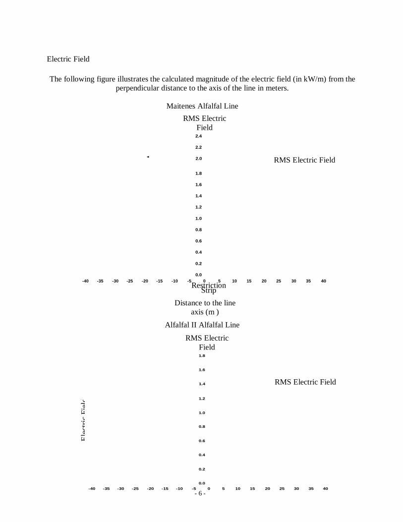
Electric Field
The following figure illustrates the calculated magnitude of the electric field (in kW/m) from the perpendicular distance to the axis of the line in meters.
Maitenes Alfalfal Line
RMS Electric Field
2.4
2.2
2.0 RMS Electric Field
1.8
1.6
1.4
1.2
1.0
0.8
0.6
0.4
0.2
0.0
-40 -35 -30 -25 -20 -15 -10 -5 0 5 10 15 20 25 30 35 40 Restriction Strip
Distance to the line axis (m )
Alfalfal II Alfalfal Line
RMS Electric Field
1.8
1.6
1.4
RMS Electric Field
1.2
1.0
0.8
0.6
0.4
0.2
0.0
-40 -35 -30 -25 -20 -15 -10 -5 0 5 10 15 20 25 30 35 40

- 7 -
Restriction Strip
Distance to the line axis (m )
Figure 2: RMS Electric Field Magnitude of lines

- 8 -
Based on this model the greater value obtained for the Electric Field for the end values in the restriction strip (15m from the line axis for Maitenes Alfalfal Line and 20m for Alfalfal II Alfalfal Line) was 0.56 (kW/m) for the Maitenes Alfalfal Line and 0.134 (kW/m) for the Alfalfal II Alfalfal Line. The highest value for the electric field for the whole range evaluated was 2.1 (kW/m) and 1.56 (kW/m) respectively.

- 9 -
Elec
tric
Fiel
d (k
W/m
)
Comparison with International Standards
There are at least six (6) international standards explicitly addressing the maximum magnitude of the electric field in the proximity of the high voltage lines and, specifically for exposure of the public in general. The countries of origin of the mostly known standards and maximum allowed values are included in the following table:
Country of origin Max. Electric Field
allowed [kW/m] Argentina 3 Australia 5 European Union 5 Florida (USA) 8 - 10 (2) (*) New York (USA) 12 (1.6) (*) Italy 5
(*) The values in brackets are the recommended values for the restriction strip.
The following chart shows the Electric field values in the end values of the restriction strip. As it can be seen these lines meet or exceed the international standard.
Electric Field 6
5
4
3
2
1
0
Argentina Australia European
Union
Florida (USA)
New York
(USA)
Italy Alf.
II-Alf. Line
Mait.-Alf. Line
Figure 3: International Standards for allowed electric fields and electric field values for the
Maitenes Alfalfal and Alfalfal II Alfalfal lines in the border of the restriction strip.

- 10 -
B [T
esla]
B
[ Te
sla]
Magnetic Field
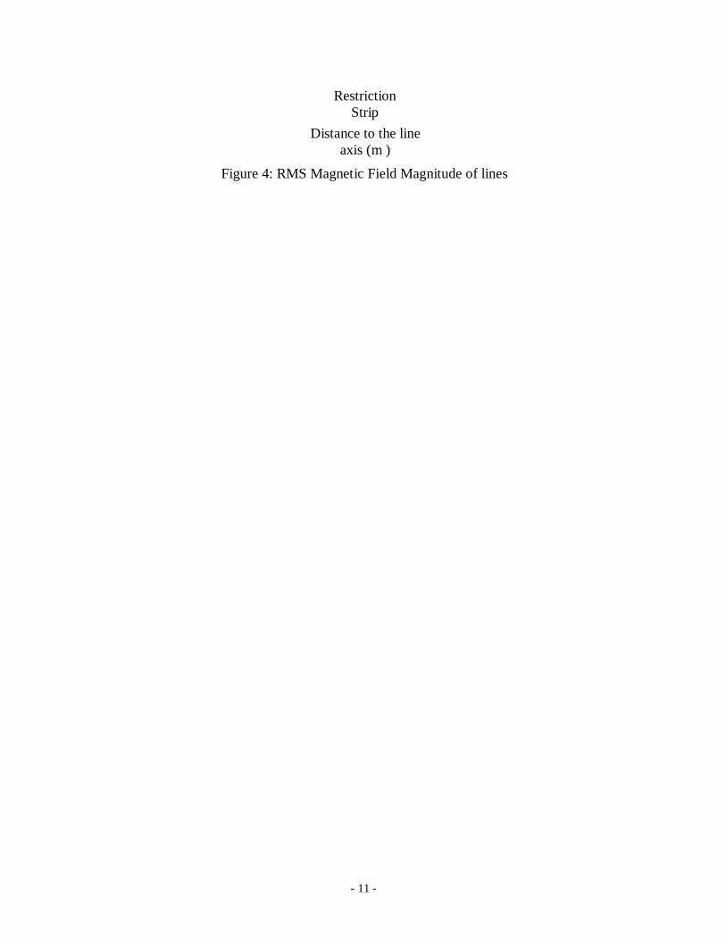
The following chart refers to the calculated magnitude of the magnetic field taken from the perpendicular distance to the axis of the line, in meters.
Maitenes Alfalfal Line
RMS Magnetic
Field 30
25 RMS Magnetic Field
20
15
10
5
0 -40 -35 -30 -25 -20 -15 -10 -5 0 5 10 15 20 25 30 35 40
Restriction Strip
Distance to the line axis (m )
Alfalfal II Alfalfal Line
RMS Magnetic Field
10
9
RMS Magnetic Field
8
7
6
5
4
3
2
1
0
-40 -35 -30 -25 -20 -15 -10 -5 0 5 10 15 20 25 30 35 40
- 11 -
Restriction Strip
Distance to the line axis (m )
Figure 4: RMS Magnetic Field Magnitude of lines

- 12 -
Based on this model the greater value obtained for the Magnetic Field for the end values in the restriction strip (15m from the line axis for the Maitenes Alfalfal Line and 20m for the Alfalfal II Alfalfal line) is 5.8 (µTesla) in the Maitenes Alfalfal line and 1.18 (µTesla) in the Alfalfal II Alfalfal line. The highest value for the magnetic field in the whole range evaluated was 27.1 (µTesla) and 9,0 (µTesla) respectively.
- 13 -
Mag
netic
Fie
ld (µ
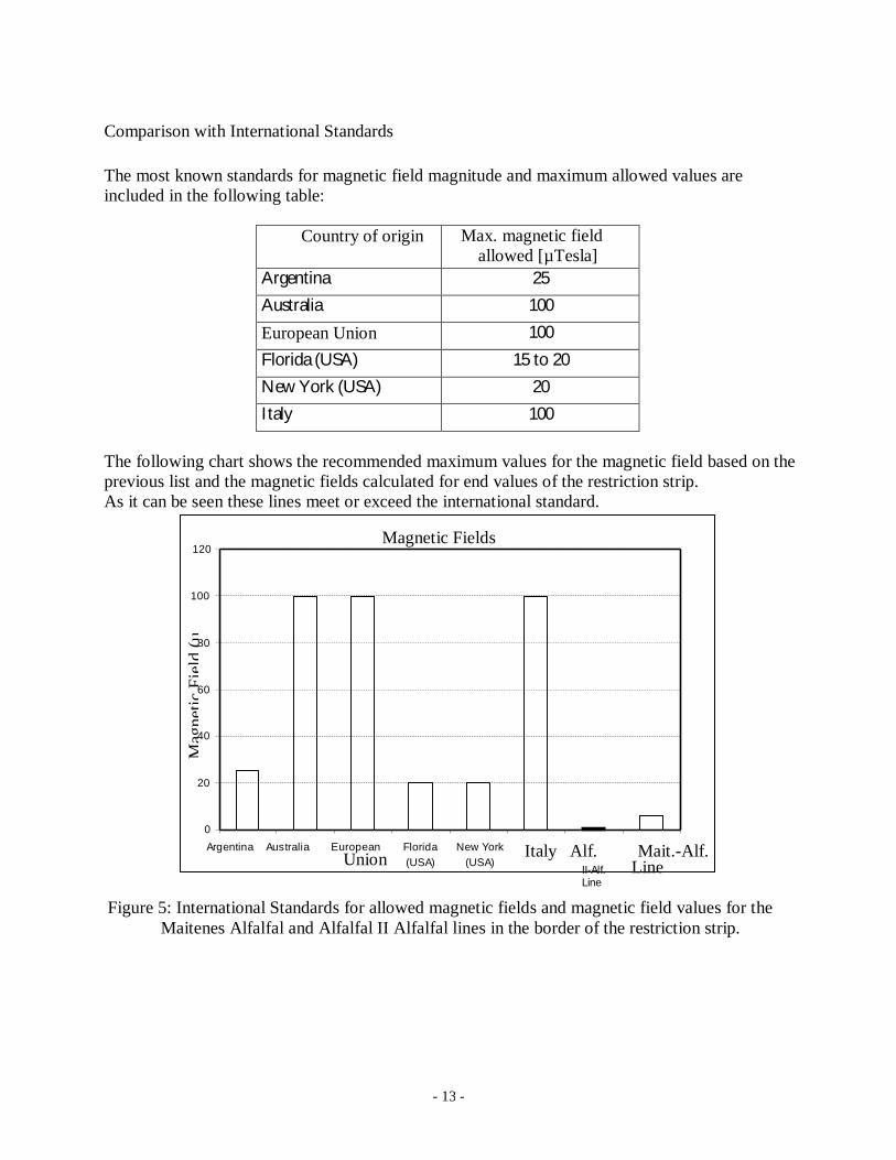
Comparison with International Standards
The most known standards for magnetic field magnitude and maximum allowed values are included in the following table:
Country of origin Max. magnetic field
allowed [µTesla] Argentina 25 Australia 100 European Union 100 Florida (USA) 15 to 20 New York (USA) 20 Italy 100
The following chart shows the recommended maximum values for the magnetic field based on the previous list and the magnetic fields calculated for end values of the restriction strip. As it can be seen these lines meet or exceed the international standard.
120 Magnetic Fields
100
80
60
40
20
0 Argentina Aus tralia European
Union
Florida (USA)
New York
(USA)
Italy Alf.
II-Alf. Line
Mait.-Alf.
Line
Figure 5: International Standards for allowed magnetic fields and magnetic field values for the Maitenes Alfalfal and Alfalfal II Alfalfal lines in the border of the restriction strip.