Anisotropic Hexagonal Boron Nitride Nanomaterials ... Anisotropic Hexagonal Boron Nitride...
62
BNL-81439-2008-BC Anisotropic Hexagonal Boron Nitride Nanomaterials - Synthesis and Applications Wei-Qiang Han To be published in “Multi Metallic and Metal Oxide Nanomaterials for Life Sciences” August 2008 Center for Functional Nanomaterials Brookhaven National Laboratory P.O. Box 5000 Upton, NY 11973-5000 www.bnl.gov Notice: This manuscript has been authored by employees of Brookhaven Science Associates, LLC under Contract No. DE-AC02-98CH10886 with the U.S. Department of Energy. The publisher by accepting the manuscript for publication acknowledges that the United States Government retains a non-exclusive, paid-up, irrevocable, world-wide license to publish or reproduce the published form of this manuscript, or allow others to do so, for United States Government purposes. This preprint is intended for publication in a journal or proceedings. Since changes may be made before publication, it may not be cited or reproduced without the author’s permission.
Transcript of Anisotropic Hexagonal Boron Nitride Nanomaterials ... Anisotropic Hexagonal Boron Nitride...

BNL-81439-2008-BC
Anisotropic Hexagonal Boron Nitride Nanomaterials
- Synthesis and Applications
Wei-Qiang Han
To be published in “Multi Metallic and Metal Oxide Nanomaterials for Life Sciences”
August 2008
Center for Functional Nanomaterials
Brookhaven National Laboratory P.O. Box 5000
Upton, NY 11973-5000 www.bnl.gov
Notice: This manuscript has been authored by employees of Brookhaven Science Associates, LLC under Contract No. DE-AC02-98CH10886 with the U.S. Department of Energy. The publisher by accepting the manuscript for publication acknowledges that the United States Government retains a non-exclusive, paid-up, irrevocable, world-wide license to publish or reproduce the published form of this manuscript, or allow others to do so, for United States Government purposes. This preprint is intended for publication in a journal or proceedings. Since changes may be made before publication, it may not be cited or reproduced without the author’s permission.

DISCLAIMER
This report was prepared as an account of work sponsored by an agency of the United States Government. Neither the United States Government nor any agency thereof, nor any of their employees, nor any of their contractors, subcontractors, or their employees, makes any warranty, express or implied, or assumes any legal liability or responsibility for the accuracy, completeness, or any third party’s use or the results of such use of any information, apparatus, product, or process disclosed, or represents that its use would not infringe privately owned rights. Reference herein to any specific commercial product, process, or service by trade name, trademark, manufacturer, or otherwise, does not necessarily constitute or imply its endorsement, recommendation, or favoring by the United States Government or any agency thereof or its contractors or subcontractors. The views and opinions of authors expressed herein do not necessarily state or reflect those of the United States Government or any agency thereof.

1
Anisotropic Hexagonal Boron Nitride Nanomaterials – Synthesis and Applications
Wei-Qiang Han
Center for Functional Nanomaterials, Brookhaven National Laboratory, Upton, NY 11733
1. Introduction
Boron nitride (BN) is a synthetic binary compound located between III and V group
elements in the Periodic Table. However, its properties, in terms of polymorphism and
mechanical characteristics, are rather close to those of carbon compared with other III-V
compounds, such as gallium nitride. BN crystallizes into a layered or a tetrahedrally
linked structure, like those of graphite and diamond, respectively, depending on the
conditions of its preparation, especially the pressure applied. Such correspondence
between BN and carbon readily can be understood from their isoelectronic structures [1,
2]. On the other hand, in contrast to graphite, layered BN is transparent and is an
insulator. This material has attracted great interest because, similar to carbon, it exists in
various polymorphic forms exhibiting very different properties; however, these forms do
not correspond strictly to those of carbon.
Figure 1. Crystal structures of (a) graphite; (b) hexagonal boron nitride
Crystallographically, BN is classified into four polymorphic forms: Hexagonal BN
(h-BN) (Figure 1(b)); rhombohedral BN (r-BN); cubic BN (c-BN); and wurtzite BN (w-
BN). BN does not occur in nature. In 1842, Balmain [3] obtained BN as a reaction
product between molten boric oxide and potassium cyanide under atmospheric pressure.
BNL-81439-2008-BC

2
Thereafter, many methods for its synthesis were reported. h-BN and r-BN are formed
under ambient pressure. c-BN is synthesized from h-BN under high pressure at high
temperature while w-BN is prepared from h-BN under high pressure at room temperature
[1].
Each BN layer consists of stacks of hexagonal plate-like units of boron and nitrogen
atoms linked by SP2 hybridized orbits and held together mainly by Van der Waals force
(Fig 1(b)). The hexagonal polymorph has two-layered repeating units: AA’AA”… that
differ from those in graphite: ABAB… (Figure 1(a)). Within the layers of h-BN there is
coincidence between the same phases of the hexagons, although the boron atoms and
nitrogen atoms are alternatively located along the c-axis. The rhombohedral system
consists of three-layered units: ABCABC…, whose honeycomb layers are arranged in a
shifted phase, like as those of graphite.
Reflecting its weak interlayer bond, the h-BN can be cleaved easily along its layers,
and hence, is widely used as a lubricant material. The material is stable up to a high
temperature of 2300 ºC before decomposition sets in [2] does not fuse a nitrogen
atmosphere of 1 atm, and thus, is applicable as a refractory material. Besides having such
properties, similar to those of graphite, the material is transparent, and acts as a good
electric insulator, especially at high temperatures (10 6 Ωm at 1000 ºC) [1].
c-BN and w-BN are tetrahedrally linked BN. The former has a cubic sphalerite-type
structure, and the latter has a hexagonal wurtzite-type structure. c-BN is the second
hardest known material (the hardest is diamond), the so-called white diamond. It is used
mainly for grinding and cutting industrial ferrous materials because it does not react with
molten iron, nickel, and related alloys at high temperatures whereas diamond does [1]. It
displays the second highest thermal conductivity (6-9 W/cm.deg) after diamond.
This chapter focuses principally upon information about h-BN nanomaterials, mainly
BN nanotubes (BNNTs), porous BN, mono- and few-layer-BN sheets. There are good
reviews book chapters about c-BN in [1, 4-6].
2. Synthesis of BN nanotubes
2.1. Introduction

3
Iijima’s discovery of carbon nanotubes (CNTs) in 1991 [7] occasioned intense
experimental- and theoretical-researches during the last decade on other hollow tubular
structures, i.e. inorganic nanotubes, because of the various intriguing properties
associated with their small dimensions, high anisotropy, and interesting structures.
Among such inorganic nanotubes, BNNT received the most attentions. h-BN has a
layered structure to very similar to that of graphite; its tubular forms were predicated
theoretically [8] before they were successfully produced [9]. Indeed, in 1981, Ishii et al.
already had reported the formation of h-BN “whiskers”, that, in modern terminology, are
called bamboo-like BNNTs, by heating oxidized BN powder [10]. Electronic-band
structure calculations show that BNNTs, whose diameters are larger than 0.80 nm, are
wide-band-gap semiconductors with a gap value of ~ 5.5 eV. Interestingly, and in sharp
contrast to CNTs, this gap value is independent of their chirality and diameter [11]. The
ionic B-N bonding in BNNTs provides richer, but more complex structural properties
than those of CNTs. Accordingly, BNNTs may be more useful than CNTs for certain
applications in electronic devices such as nanoscale insulating materials. Besides BNNTs,
BxCyNz nanotubes have also been widely studied [12-14]; here I introduce only non-
carbon pure BNNTs.
Figure 2. (a) Simulated image of a single-walled BNNT (5 5); (b) simulated image of a double-walled BNNT; (c) high-resolution TEM images of a series of individual nanotubes with numbers of walls from 1 to 4; (d) EELS spectrum of a BNNT.

4
Multi-walled and single-walled-BNNTs were firstly prepared, respectively, in 1995
[9] and 1996 [15]. Figure 1(a) and (b) are simulated images of a single-walled BNNT (5,
5) and a double-walled BNNT, respectively. Figure 1(c) shows high-resolution
transmission electron microscopy (TEM) images of BNNTs, ranging from single layered
to four layered ones. Figure 1(d) is an electron energy loss spectrum (EELS) of a BNNT.
BNNTs have been synthesized by several methods: Arc-discharge method [9]; laser
heating/ablation [16]; CNT-substitution reactions [17]; chemical vapor deposition (CVD)
[18]; solid-gas reaction [19]; low-temperature autoclave [20]; pore-template [21]; and arc-
jet plasma [22].
2.2. Arc-discharge
Chopra et al. reported in 1995 the first synthesis of pure crystalline BNNTs by an arc-
discharge method [9]. This synthetic route employs a high-temperature arc plasma similar
to that used in the conventional production of CNTs. A tungsten rod loaded with pressed
h-BN was arc-discharged against a cooled copper cathode, generating in numerous multi-
walled BNNTs with B:N ratio of ~ 1, as confirmed by EELS and consistent with
theoretical prediction. The spacing distance of BNNTs is 0.33 nm, in agreement with the
spacing distance of 0.333 nm in bulk h-BN. Later, Loiseau et al. also synthesized BNNTs
by the arc-discharge method [15]. The establishment of a carbon-free plasma between
HfB2 electrodes in a nitrogen atmosphere lead to the formation of BNNTs with very few
layers, including single- and double-layer ones [15].
Figure 3. Simulated image of a arc-discharge chamber. The conductive ingots are mounted as
both anodes and cathode (the end of yellow lines)
5
Cumings and Zettl [23] modified the arc-discharge method by using conductive boron
ingots as electrodes. The electrodes are formed by first thoroughly mixing elemental
boron (99.5 % pure) with 1 atomic percent each of nickel and cobalt. After heating the
mixture to its melting point in a copper-hearth arc furnace, it was cooled to form a
macroscopically homogenous ingot. Using a crude two-probe method, the electrical
resistivity of the ingots was measured to be less than 50 milliohmmeters. When the
metals are not added, the conductivity of the boron ingots is insufficient to support the arc.
The ingots themselves are mounted as both anode and cathode in a conventional-design
water-cooled nanotube direct-current arc synthesis chamber (see Figure 3). The chamber
is pumped down to less than 30 mtorr and then backfilled with N2 gas with the pressure
dynamically stabilized to 380 torr. During a synthesis, the arc current is sustained
nominally at 60 amperes DC, with the electrode voltage ranging from 30 to 45 V. During
the arc, a gray web-like material grows preferentially near the top of the chamber, while a
thin layer of gray soot is deposited on its side walls. Both contain an abundance of
BNNTs, although the web-like material is significantly richer in them. This method can
produce about 70% double-walled nanotubes (Figure 4), within ~ 10% single-walled
nanotubes and fewer multi-walled nanotubes.
Figure 4. High-resolution TEM image of BNNTs made by arc-discharge method.
In the by-products, there is a large amount of BN fullerene-like nanoparticles (FNPs,
or so-called nanococooons). HRTEM images together with EELS and electron-diffraction
data revealed that these nanoparticles were B-rich nanocrystals coated with a few layers
of graphitic BN; some of them contained cobalt and nickel impurities. The BN FNPs

6
ranged widely in size, from 5 to 100 nm. There was no clear correlation between the
number of BN layers of the FNPs and their diameter. In general, only a few layers of
graphitic BN were observed. But interestingly, very frequently the FNPs consisted of two
layers of BN. Two types of contact between the FNPs and nanotubes were noted. In the
first type, the FNPs were found on the side walls of nanotubes clearly distinct from them;
presumably, these FNPs were attached by Van der Waals’ forces. The second type of
contact took place at the end of nanotubes wherein the BN sheets were continuous
between the FNPs and the nanotubes. The nanotube-FNP junctions occurred at the
corners, rather than the facets [24]. In these samples, no transition metals were detected
in any particle from which a nanotube grew. Hence, the transition metals simply may
serve as dopants, enhancing the conductivity of the boron ingots. The possible growth
mechanism is follows: The plasma contains various sized droplets of molten boron from
the ingots, boron vapor, and nitrogen vapor; the larger droplets fall to the bottom of the
chamber, while the smallest ones, nanometers in diameter, remain in the plasma. During
their exposure to the plasma, boron and nitrogen atoms react on their surfaces to form BN
sheets, probably after the droplets have solidified. The sheets have one or more layers;
two is the commonest configuration. These sheets continue to extend whilst remaining
flat. To introduce curvature there must be defects at the junction of two or more flat
sheets. These defects are loci of nanotube growth. As boron and nitrogen atoms continue
to be added to the sheets, they are incorporated into growing nanotubes at the tube’s base.
Nanotube growth ends when the particle is transported out of the zone of hot gas [24].
BNNTs also were prepared by arc-melting ZrB2 [25], NbB2 [26], YB6 [26], YB6/Ni
[26], and BN-Ta [27] powder in a nitrogen/argon gases.
2.3 Laser ablation
Golberg et al. [16] heated BN with a laser in a diamond anvil cell at high nitrogen
pressure (5-15 GPa) to prepare BNNTs with 3-8 layers. These nanotubes were grown
either in melted cubic BN, or in hexagonal + amorphous BN that had re-crystallized on
the specimen’s surface from the fluid phase. Yu et al.[28] produced BNNTs by using
excimer-laser ablation at 1200 ºC. The target was a mix of BN powder with Ni and Co

7
nanoparticles (1% each). The resulting nanotubes have one or a few layers. Their tips
either are flat caps or polygonal terminations, in contrast to the conical ends of CNTs [28].
Continuous CO2 lasers also were used to generate BNNTs with or without metal catalysts
[29, 30].
Arenal et al. [31] demonstrated the production of high-quantity single-walled BNNTs
by laser ablation without using any metal catalyst. They repeatedly bombarded an h-BN
target with a CO2 (wavelength 10.6 µm) continuous laser under a partial pressure of
nitrogen gas [31]. The temperature at the surface of the target was 3200-3500k based on
measurement via an optical pyrometer. They also took the temperature of the nitrogen gas
by coherent anti-Stokes Raman scattering (CARS) as a function of the distance to the
target’s surface [32]. Reportedly, the nitrogen gas near the target’s surface is heated up to
its temperature and acts as a local furnace. Above the target, its temperature decreases
first rapidly, and then more slowly until, as a distance of 7 mm above the target’s surface,
it is around 1200 K. They found that the optimized power lies between 1000 and 1200 w,
equivalent to a temperature at the target’s surface above 2400 ºC. The yield of the raw
products is about 0.5 g/h. The reaction products were collected on the filter and in a trap
located in the outlet of the reactor chamber. Eighty percent of the nanotubes are single
walled; the others are multi-walled with very few layers. The length and diameter of
nanotubes typically are several hundred nm, and 2 nm, respectively.
Combining the techniques of TEM and EELS [33], Arenal and his colleagues later
reported that nearly spherical nanoparticles (or so-called cages) generally consist of a
core of a pure boron particle covered by a thin layer of boron oxide, wrapped with h-BN
shells. The same nanoparticles often are found at the ends of nanotubes. Though these
nanoparticles are only a few nanometers (≤ 10 nm), very often they are larger than that of
the tubes. Sometimes, a few tubes assembled into a bundle seem to emerge from the same
particle.
Based on these results, these authors proposed a root-growth mechanism originating
in pure boron particles for the formation of BNNTs. Their modified vapor-liquid-solid
(VLS) growth model for the formation of SW-BNNTs is illustrated in Figure 5.

8
Figure 5. Sketches showing the phenomenological model for the formation of the tubes (a), and of the cages of BN (b). (a) The model is as follows: (a-i) formation of boron drops from the decomposition of h-BN and from the boron oxide of the target; (a-ii) reaction of these drops of boron with the nitrogen injected into the reaction chamber and with that coming from the h-BN target. Recombination of the boron and nitrogen to form boron nitride; (a-iii) incorporation of the nitrogen atoms at the root of the boron particle from which the tube grows. Concerning the cages and the carbon and boron oxide filling them (carbon may also be found inside some BNNTs), the growth mechanism is (b-i) and (b-ii) these steps correspond to (a-i) to (a-iii) taking into account the dissolution of oxygen and carbon in the boron drops; (b-iii) and (b-iv) correspond to the segregation of the carbon and oxygen. For carbon, the segregation occurs at temperatures close to 2000 °C, whereas oxygen segregation at lower temperatures, around 700 °C. (Reproduced with permission from Ref. 31. Copyright 2007 American Chemical Society)
According to the thermodynamic phase diagram of the B-N system, upon heating by
the laser beam, the h-BN compound of the target does not sublimate as does graphite, but
decomposes above 2600 K into gaseous nitrogen and liquid boron. Boron then is
vaporized even though the equilibrium vaporization temperature is far from that realized
at the target’s surface. Above 1800 ºC, the boron-oxide binding also is decomposed and
vaporized. Therefore, there are two sources of boron available to form the nanotubes; the
efficiency of their formation is less with boron oxide. Upon cooling within the
temperature gradient created by the flow of nitrogen gas, the boron vapor condenses into
small droplets. When the temperature falls below 2700 K, the droplets react with the
nitrogen gas to form a sp2 BN structure. Despite the strong stability of the nitrogen
molecule, the high reactivity of the liquid boron’s surface at 2700 K can degrade this
molecule. The source of the nitrogen gas either is the carrier gas or issued from the
decomposition of the BN target. This latter was confirmed as the source by using argon
as the carrier gas [31]. As a consequence of the chemical reaction B-N2, a sp2 BN cap is
formed at the surface of the particle (step I in Figure 5). It progressively is transformed
into a tube by the continuous supply and the decomposition of nitrogen at the surface of
the particle (step II in Figure 5). This finding implies that initially the size of the BN cap

9
to be less than that of the particle; thereby, its surface would be ensured free access to the
nitrogen gas. The nucleation process implies a root growth mechanism wherein nitrogen
and boron atoms are incorporated in the BN network at the foot of the nanotube via its
interface with the particle’s surface where the bonds are the most active. In this
mechanism, the boron particle has a dual role, as a support for growth, and a reactant.
This pattern of growth persists as long as the boron particle is liquid (i.e., as long as
the temperature is above 2300 K (step II in Figure 5)). The boron particle begins to
solidify in a zone of the reactor chamber where the cooling rate is between 100 and 200
K/ms. Accordingly, the growth of the tubes abruptly stops, so explaining the relative
short length of SW-BNNTs compared to their carbon analogs synthesized via a
continuous CO2 laser vaporization of a NiCo-graphite target [34]. Finally, when the
boron solidifies, the nitrogen atoms remaining at the surface of the particle react with
surface boron atoms to build a BN sheet encapsulating the B particle.
In summary, the growth process involves three steps: (1) The laser-induced
decomposition of boron oxide contained in the target’s binder and in its h-BN crystallites
into nitrogen gas and liquid boron, both of which finally are vaporized; (2) Upon cooling,
boron vapor condenses into small boron liquid droplets that react with nitrogen gas, either
coming from the carrier gas or issued from the decomposition of the target, to form BN
caps at the droplets surface; (3) Growth of the nanotubes from the progressive
incorporation of nitrogen and boron at the interface between the cap and the particle. The
growth stops on the solidification of this core particle of boron.
Plasma-enhanced pulsed-laser deposition (PE-PLD) was used to generate multi-
walled BNNTs directly on substrates at 600 ºC. Oxidized Si substrates with Fe films
(12.5 nm) were installed on the heater and sealed inside the vacuum chamber at base
pressures up to ~5 x 10⁻⁷ mbar. With a RF generator (13.56 MHz) capacitively coupled to
a steel substrate holder, plasma was generated on the substrate’s surface over 10 minutes.
This RF plasma induced negative dc voltages on the substrates, so-called substrate bias,
that accelerates the positive ions in the rf plasma and the BN vapor to bombard on the
substrate’s surface between -360 and -450 V. When sufficiently high kinetic energies of
these ions are achieved, the deposition rate of BN films is balanced by the rate of re-
sputtering and result in total re-sputtering [35].

10
Figure 6. SEM images of BNNT bundles grown at a substrate bias of (A) -380 V, and (B) -450 V and (C) their corresponding bundling configurations (left and right, respectively). (D) Patterned growth of BNNTs. (Reproduced with permission from Ref. [35]. Copyright 2005 American Chemical Society)
Scanning electron microscopy (SEM) revealed that multiple BNNTs grown from
adjacent Fe catalyst particles tend to form vertical bundles. BNNTs grown at -380 V
appear conical, as shown in Figure 6A. For samples grown at higher substrate bias (-450
V), individual BNNTs inside the bundles can be resolved clearly because of the increase
in the diameters (~20 nm) of individual BNNT grown from larger Fe nanoparticles that
formed by the enhanced plasma heating (Figure 6B). Figure 6C depicts the bundling
configurations of BNNTs with such small (left) and large (right) diameters. These BNNT
bundles can be grown into arrays of regular patterns (Figure 6D) with a patterned Fe film
created by a shadow mask. These results demonstrated that the location of BNNTs is
controllable during their growth by the patterns of the Fe nanoparticles [35].
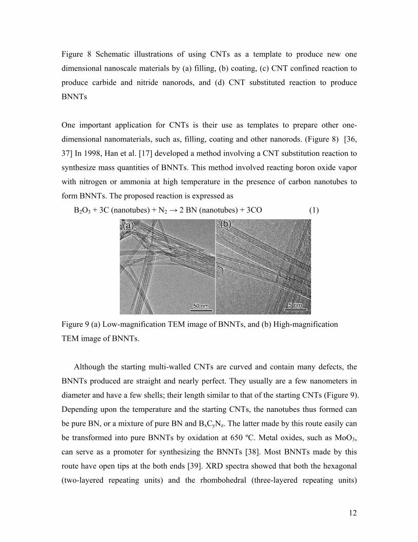
Figure 7. Schematic drawing representing the growth region of BNNTs. (A) Deposition of BN films on Fe nanoparticles due to low re-sputtering rate of the growth species. (B) Reduced growth rate of BN films with an energetic growth species. (C) Total re-sputtering region wherein BNNTs grow and BN films are suppressed (Reproduced with permission from Ref. [35]. Copyright 2005 American Chemical Society)
11
The growth of these BNNTs is obtained through an optimum combination of the Fe
film’s thickness, the laser’s energy density (deposition rate), and the substrate bias. For
example, for substrate with 12.5 nm thick Fe film at a substrate bias of -300 V, the
resultant excessive deposition rate generates a coating of BN films on the Fe
nanoparticles (Figure 7A). These insulating BN coatings are recognized by the charging
effect during the SEM measurement; in such cases, the growth of BNNTs is difficult to
identify. Under these conditions, the deposition rate of BN films is faster than the
diffusion rate of the BN growth species into the Fe catalyst particles. Thus, the BN films
coated on the catalyst terminate the contact between Fe and the reactive growth species
(Figure 7A); this phenomenon is termed the poisoning effect. The thickness of BN films
gradually decreases as the substrate bias increases (Figure 7B). BNNTs start to grow at a
higher substrate bias as a balance is reached between the rate of film deposition and re-
sputtering rate (Figure 7C). At this total re-sputtering region, there is suppression of the
deposition of BN thin films. BNNTs grow on the Fe nanoparticles according to the VLS
mechanism. The rf plasma creates a directional flux of the BN growth species with
sufficient kinetic energies to diffuse into the Fe nanoparticles. Thus, the Fe captures the
energetic BN growth species and confines them in a nanoscopic space; otherwise, they
are re-sputtered off. Supersaturation of the Fe nanoparticles with BN vapor causes the BN
species to condense into ordered nanotubular structures [35].
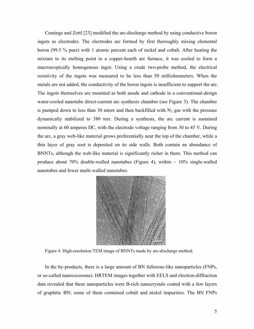
2.4 Carbon nanotubes-substitution reaction
12
Figure 8 Schematic illustrations of using CNTs as a template to produce new one
dimensional nanoscale materials by (a) filling, (b) coating, (c) CNT confined reaction to
produce carbide and nitride nanorods, and (d) CNT substituted reaction to produce
BNNTs
One important application for CNTs is their use as templates to prepare other one-
dimensional nanomaterials, such as, filling, coating and other nanorods. (Figure 8) [36,
37] In 1998, Han et al. [17] developed a method involving a CNT substitution reaction to
synthesize mass quantities of BNNTs. This method involved reacting boron oxide vapor
with nitrogen or ammonia at high temperature in the presence of carbon nanotubes to
form BNNTs. The proposed reaction is expressed as
B2O3 + 3C (nanotubes) + N2 → 2 BN (nanotubes) + 3CO (1)
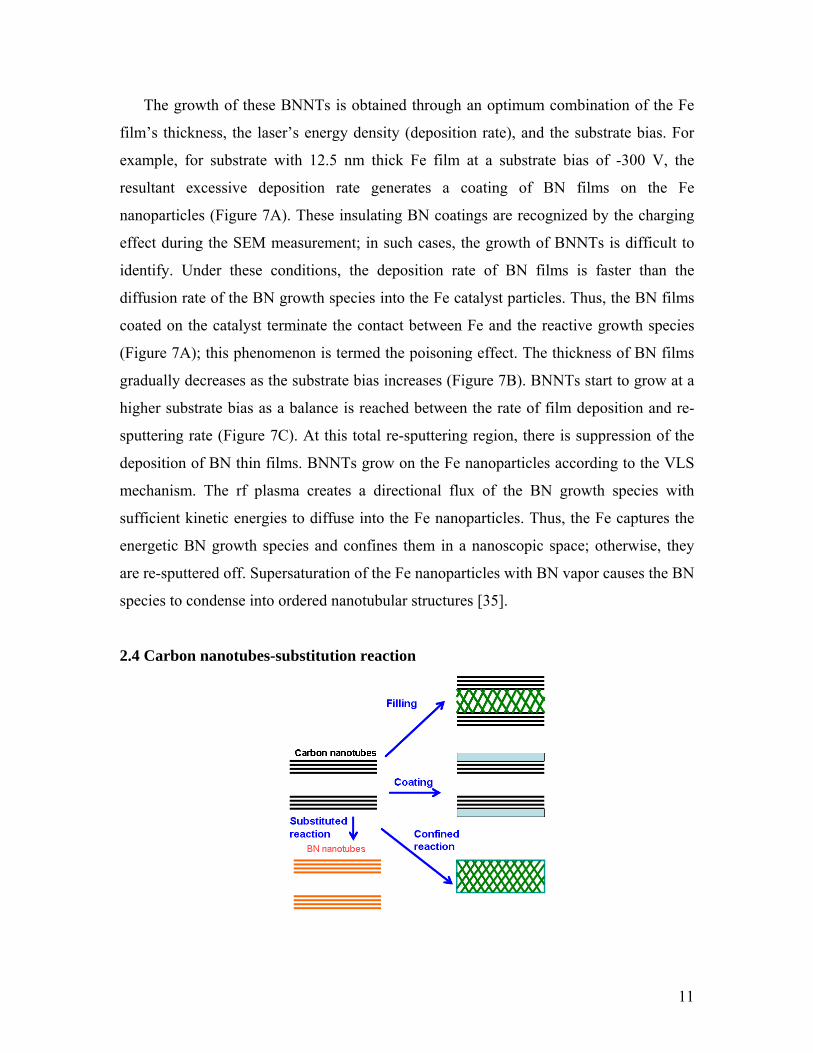
Figure 9 (a) Low-magnification TEM image of BNNTs, and (b) High-magnification
TEM image of BNNTs.
Although the starting multi-walled CNTs are curved and contain many defects, the
BNNTs produced are straight and nearly perfect. They usually are a few nanometers in
diameter and have a few shells; their length similar to that of the starting CNTs (Figure 9).
Depending upon the temperature and the starting CNTs, the nanotubes thus formed can
be pure BN, or a mixture of pure BN and BxCyNz. The latter made by this route easily can
be transformed into pure BNNTs by oxidation at 650 ºC. Metal oxides, such as MoO3,
can serve as a promoter for synthesizing the BNNTs [38]. Most BNNTs made by this
route have open tips at the both ends [39]. XRD spectra showed that both the hexagonal
(two-layered repeating units) and the rhombohedral (three-layered repeating units)

13
nanotubes exist in the final product [17], as was confirmed by TEM (Figure 10) [40].
Pure BN conical nanotubes also were obtained by this method (Figure 11) [41-43], while
aligned BxCyNz nanotubes and BNNTs resulted from using aligned CNTs and aligned
CNx nanotubes as templates [14, 44].
Figure 10 HRTEM images of multi-walled BN NTs. A definite, but different stacking order is apparent in marked areas in (a) and (b) as highlighted in the insets. Hexagonal type stacking in (a) and rhombohedral-type stacking in (b) are confirmed by corresponding computer simulated HRTEM images (right-hand side images) for BNNTs having the axes parallel to the [1 0 -10]orientation (zigzag tubes) (Reproduced with permission from Ref. 40. Copyright 2000 American Institute of Physics).
Figure 11 TEM image and schematic of a conical BNNT.

14
Han et al. showed that CNTs made by CVD contain many defects, the preferred sites
for the substitution reaction. Advantageously, boron oxide can flow into the hollows of
nanotubes with open tips or breaches so the reaction can start from both outer- or inner-
layers [45]. Bando et al. confirmed this assumption based on EELS mapping results,
suggesting that the conversion of carbon to BN in the tubular layers occurs through
inhomogeneous crystallization of B/N domains onto and within undulating defective
graphite C shells opened by oxidation [46]. These models can simply explain the major
growth processes, but they cannot explain some important phenomena, such as that the
outer and inner diameters of BNNTs (typically are 3-9 nm and 2-4 nm, respectively) are
smaller than those of the starting carbon nanotubes (typically are 8-15 nm and 4-7 nm,
respectively), and the decrease in the number of layers.
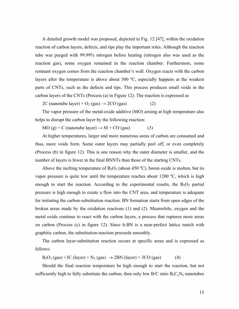
Figure 12 A schematic processes for carbon nanotube-substitution reaction that develop with temperature (T) and time (t). (a) Areas of voids in carbon layers that are formed by their oxidation reactions with oxygen or metal oxides (MO); (b) More voids form in the carbon layers, and some outer layers peel off; (c) B2O3 and nitrogen react with the carbon layers to form BN domains, and more voids are formed in the carbon layers; (d) The substitution reactions are completed with all BN layers having numerous large voids; and (e) The inner and outer diameters of BN start shrinking by the rearrangement of B and N atoms so to eliminate to the large voids, yielding near-perfect layers of BNNTs (Reproduced with permission from Ref. 47. Copyright 2006 American Institute of Physics).
15
A detailed growth model was proposed, depicted in Fig. 12 [47], within the oxidation
reaction of carbon layers, defects, and tips play the important roles. Although the reaction
tube was purged with 99.99% nitrogen before heating (nitrogen also was used as the
reaction gas), some oxygen remained in the reaction chamber. Furthermore, some
remnant oxygen comes from the reaction chamber’s wall. Oxygen reacts with the carbon
layers after the temperature is above about 500 ºC, especially happens at the weakest
parts of CNTs, such as the defects and tips. This process produces small voids in the
carbon layers of the CNTs (Process (a) in Figure 12). The reaction is expressed as
2C (nanotube layer) + O2 (gas) → 2CO (gas) (2)
The vapor pressure of the metal-oxide additive (MO) arising at high temperature also
helps to disrupt the carbon layer by the following reaction:
MO (g) + C (nanotube layer) → M + CO (gas) (3)
At higher temperatures, larger and more numerous areas of carbon are consumed and
thus, more voids form. Some outer layers may partially peel off, or even completely
(Process (b) in figure 12). This is one reason why the outer diameter is smaller, and the
number of layers is fewer in the final BNNTs than those of the starting CNTs.
Above the melting temperature of B2O3 (about 450 ºC), boron oxide is molten, but its
vapor pressure is quite low until the temperature reaches about 1200 ºC, which is high
enough to start the reaction. According to the experimental results, the B2O3 partial
pressure is high enough to create a flow into the CNT area, and temperature is adequate
for initiating the carbon-substitution reaction. BN formation starts from open edges of the
broken areas made by the oxidation reactions (1) and (2). Meanwhile, oxygen and the
metal oxide continue to react with the carbon layers, a process that ruptures more areas
on carbon (Process (c) in figure 12). Since h-BN is a near-perfect lattice match with
graphitic carbon, the substitution-reaction proceeds smoothly.
The carbon layer-substitution reaction occurs at specific areas and is expressed as
fellows:
B2O3 (gas) +3C (layer) + N2 (gas) → 2BN (layer) + 3CO (gas) (4)
Should the final reaction temperature be high enough to start the reaction, but not
sufficiently high to fully substitute the carbon, then only low B/C ratio BxCyNz nanotubes

16
are formed [46]. At 1500 ºC, the main boron oxide is B2O2, which is mainly formed by
the reaction below:
B2O3 (liquid) + CO (gas) → B2O2 (gas) + CO2 (gas) (5)
The carbon substitution reaction then is written as:
B2O2 (gas) + 2C (layer) + N2 (gas)→ 2BN (layer) + 2CO (gas) (6)
At a steady temperature of 1580 ºC, most or all of the carbon layers have been
replaced by BN layers via reactions (4) and (6), or consumed by oxygen or metal oxide in
reactions (2) and (3), leaving small or large voids (process (d) in the figure 14).
However, since the temperature is high enough, BN atoms can be in a near-fusion
state and rearrange to eliminate these voids. Then, the diameter of the inner layer of
BNNTs tends to shrink such that the B and N atoms in the same layer are numerous
enough to settle into a perfect cylinder, which makes the structures more energetically
stable. The final inner and outer diameters might be regulated by the size of the open-tips
that can range from very small one to that of the original diameters of the nanotubes.
Such rearrangement of BN atoms, corresponding to the shrinking of the diameter, thus
starts from the tip area and extends along the whole length of the tube. This process leads
to BNNTs with inner and outer diameters much smaller than those of the starting CNTs.
Indeed, some B and N atoms can migrate between the different layers. Hence, outer
layers might be eliminated by the occurrence of such migration to inner layers to mend
the voids therein. In this way, the number of layers in the BNNTs is reduced (Process (e)
in figure 12). The process (d) and (e) can happen simultaneously. Finding with EELS
show that the atomic ratio of B/N usually is closed to 1, signifying that that B and N
atoms preferentially rearrange and migrate as a pair. Frequently, there are double or
triple-layered BNNTs along with single-walled ones. In addition, the process of
rearrangement and fusion of the B and N atoms are similar to the graphitization process
in the carbon layers of CNTs during heating and irradiation by an electron beam during
in-situ TEM observations [48].
This model also is good for explaining the formation of nearly-perfect BxCyNz
nanotubes with very high B/C atomic ratios that similarly exhibit much narrower outer
and inner diameters compared with those of the starting carbon nanotubes.
17
The CO gas formed during the reactions (2), (3), (4), and (6) can also react with B2O3
and N2 to form BN in the following manner:
B2O3 + 3CO + N2→ 2BN + 3 CO2 (7)
This reaction may help mend the voids in BN layers, or, form new BN layers on
existing inner or/and outer ones. However, it is also the main source for the formation of
by-products, such as BN FNPs and BN pieces. If the reaction temperature is too high,
reaction (7) will predominate and thus, more BN by-products will be produced.
Using this route, isotopic 10BN and 11BNNTs respectively were synthesized by
replacing natural B2O3 with 10B2O3 and 11B2O3 [47, 49].
2.5 Chemical vapor deposition
CVD involves the dissociation and/or chemical reactions of gaseous reactants in an
activated (heat, light, plasma) environment, followed by the formation of a stable solid
product. The deposition involves homogeneous gas-phase reactions, which occur in the
gas phase, or heterogeneous chemical reactions, which occur on/near the vicinity of a
heated surface, or both, leading to the formation of powders, films, and 1D-nanomaterials,
respectively. CVD is a successful route to synthesize high-purity and good-quality CNTs.
It also is expected to be invaluable in synthesizing highly pure BNNTs.
Lourie et al. used borazine (B3N3H6) as a precursor and nickel boride as a catalyst to
synthesize BNNTs at 1100 ºC. They made borazine by an in-situ reaction of (NH4)2SO4
with NaBH4 [18]. The produced nanotubes have large diameters and exhibit a bamboo-
like structure.
Using B and MgO as staring materials to react with ammonia, Tang et al. formed
BNNTs. At 1300 ºC, boron reacted with MgO to form B2O2 and Mg vapor. The vapor
was carried by argon into a reaction chamber at 1100 ºC, and a flow of ammonia was
introduced. BN was produced by the interaction of B2O2 with ammonia [50]. The
chemical reactions are represented by the following equations:
2B(S) + 2MgO(S) → B2O2 (g) +2Mg (g) (8)
B2O2(g) + NH3 (g) → 2BN (s) +2H2O (g) + H2 (9)

18
Extensive follow-up experiments revealed that the quantity, quality, and purity of
such as-grown BNNTs strongly depend on the growth temperature when a mixture of
MgO and boron powder is employed. Below 1100 ºC, BNNTs of good quality and purity
are obtained, though the yield is only about tens of milligrams. An increase in the growth
temperature improves the yield up to hundreds of milligrams, but the nanotubes’ diameter
increase dramatically, up to one micron. Above 1250 ºC, only bulk BN flakes are
obtained. A high Mg vapor pressure at high temperature (760 mmHg at 1100 ºC) ensures
that the Mg vapor easily reaches the tube’s growth region and aggregates in this low-
temperature zone. Moreover, for growing BNNTs the catalytic activity of Mg is ideal.
However, although the mixture of MgO and boron powder has proven an effective source
for B2O2, it is extremely difficult to increase the yield by simply rising the temperature
[50].
Transition metals are common catalysts for nanotube growth. A mixture of MgO,
FeO, and boron powder is a good substitute for the precursor because the mixture
combines the advantages of MgO and FeO, which are, respectively, an effective B2O2-
producer and catalyst. The detailed experimental procedures are as fellows: An induction
furnace is used to heat the mixture of FeO, MgO, and boron powder in a BN crucible to
produce B2O2, Fe and Mg vapors. An ammonia gas introduced from the top of a BN boat
with an inner diameter of 2 cm reacts with B2O2 in the presence of a Fe catalyst. After 1h
of the reaction, a large amount of BNNTs fills the BN boat. Employing the mixture of
FeO, MgO and boron powder as a precursor, allows the synthesis of BNNTs within a
wide temperature range of 1100-1700 ºC. Temperature does not affect the purity and
diameters of the BNNT. The yield increases as the growth temperature is raised. Most
BNNTs have diameters ranging from 50 nm to 150 nm; the length can be up to a couple
of hundred micrometers (Figure 13). They lack notable impurity phases. Metal catalysts
occur at the tips of the BNNTs, suggesting that the growth of BNNTs is via the VLS
mechanism [51]. Isotopic 10BN [49] and 11BN [52] nanotubes were made by replacing
natural B with 10B and 11B, respectively.

19
Figure 13 (a) Low-magnification TEM image of BNNTs (b) High-magnification TEM image of the tip of a BNNT.
BNNTs also were synthesized via a CVD method using B-N-O precursors,
specifically, self-forming B4N3O2H intermediate compounds (oxygen content ~ 27%) or
commercial BN powders enriched with oxygen (Denka Co. oxygen content ~ 10%) [10,
53, 54]. After heating the precursor in a graphite susceptor with an induction furnace to ~
1700 ºC under flowing mixed N2/H2O or mixed N2/NH3 (15:1 in flow rates), vapors of
boron oxides (B2O3 or B2O2), decomposed from their precursors, were reduced to BNNTs
and deposited on the susceptor’s at an estimated temperature of ~ 1200 ºC.
The microwave plasma enhanced CVD method was used to prepare BNNTs with
diborane and ammonia as the reactants [55]. The chemical reaction for the formation of
BN is:
B2H6 + 2NH3 → 2BN + 6H2 (10)
Figure 14. Active species detected using quadruple mass spectroscopy (QMS) in B2H6–NH3–H2 plasma during deposition of the BNNTs. The partial pressure of every species is normalized by the total pressure in the reaction chamber. (Reproduced with permission from Ref. 55. Copyright 2008 Institute of Physics)

20
For the overall reaction in equation (10), the free energy changes are, respectively, -
165 kcal mol-1 and -177 kacl mol-1 at the reaction temperatures of 900 K and 1100 K.
Thus, BN can be processed at relatively low-temperatures by reacting diborane and
ammonia due to favorable free-energy exchanges of the reaction. Furthermore, in a
plasma environment the dissociation and ionization of gas molecules is enhanced by
activated electron and ion collisions. The electron temperature affords a measure of the
degree of the dissociation and ionization of the plasma. The average electron temperature
is estimated as ~ 10000 K for the plasma containing B2H6-NH3-H2 at 800 ºC and 800 W.
The ratio of diborane to ammonia dominates the formation of different intermediate
compounds. In this work, the [B2H6]/[NH3] ratio was 1.55:1 and Ni thin films were used
as catalysts. The results of in-situ quadruple mass spectroscopy (QMS) in B2H6-NH3-H2
during the deposition of BNNTs (Figure 14), allowed the reaction between diborane and
ammonia to be described by the following equations involving four steps: (1) the
decomposition of diborane to form BxHy, (2) the dissociation of ammonia to form NHz,
(3) the reaction of BxHy and NHz to form BNHγ and, (4) the dissociation of BNHγ for the
formation of BN.
B2H6 → BxHy + H2 (x=1-2, y=1-2) (11)
NH3 → NHz +H2 (z=0-2) (12)
BxHy + NHz → BNHγ (γ = 2) (13)
BNHγ → BN +H2 (14)
BN can deposit on the substrate area with or without Ni catalysts. However, BNNTs
only appear in areas with them. The Ni film’s thickness is one key factor affecting the
growth of BNNTs. No 1D nanostructures are observable on either a bare Si substrate
without any catalyst, or on a thick catalyst-film-coated substrate. When the film thickness
is less than 10 nm, the long nanostructures with high aspect ratios start to grow, and such
growth becomes significant when the film thickness is below 2 nm. No Ni particles were
observed attached at the tip of the nanotubes, even though the catalyst is essential for the
nanotube growth.
Hexagonal BNNTs and orthorhombic-BN (o-BN) nanotubes were prepared in a
thermal CVD furnace using trimethyl borate (TMB) and nitrogen as reactants with
reaction temperatures ranging from 1000 ºC and 1200 ºC. A 434 stainless-steel wire, 0.5

21
mm in diameter, coiled into a disk-like shape, was placed in the center area of the
chamber. At temperatures above 1000 ºC, Fe, Cr and Mo vaporize and combine with the
reactant gases to reach eutectic composition forimg a partial liquid on the surface and
form BNNTs based on the VLS growth mechanism. Their diameter is about 100 nm. At
reaction temperatures below 1000 ºC or above 1200 ºC, BN plates, beads, particles and
other morphologies are formed [56].
2.6. Solid-gas reaction
BNNTs can be generated in a reaction between solids (containing boron sources) and
gases (ammonia or nitrogen). One such type is pre-treated elemental boron powders via
ball-milling methods in an ammonia gas for 150 h at 1000 ºC, and then thermal annealing
them under a nitrogen atmosphere at 1000 ºC [19, 57-59]. This method also yielded
isotopic 10BN nanotubes [60]. BNNTs also were fabricated by nitriding boron nanowires
under a nitrogen atmosphere at 1500 ºC for 4 h [61], and boron thin film under an
ammonia atmosphere at 1175 ºC for 1 h [62].
Fe4N/B powders were annealed to prepare BNNTs exposing them at 1000 ºC for 1
hour in a nitrogen-gas atmosphere. The nanotubes, with diameters, usually larger than
100 nm, form a cup-stacked structure [63]. XRD measurements revealed Fe4N was
reduced to Fe by boron at 700 °C. The Fe nanoparticles were dispersed and adhered to
the surface of boron, until they formed a supersaturated solid solution of boron in Fe
nanoparticles that reacted with N2 gas. BNNTs grow from these sites; the diameter of the
nanotubes depends on particles’ sizes [64].
2.7. Low-temperature autoclave
BNNTs can be prepared by a low-temperature autoclaving. In a typical procedure,
Mg(BO2)2.H2O, Mg powder, NH4Cl and NaN3 are mixed and put into autoclave that is
then closed and heated at 600 ºC for 60 H. The nanotubes made via this way usually have
quite a large diameter (several hundreds of nm) and a large hollow. These nanotubes are
mixed with large amounts of BN nanocages with large hollows [65]. Using the same
22
strategy, BNNTs were produced with a yield of about 50% by co-pyrolyzing with
NH4BF4, KBH4 and NaN3 at temperatures ranging from 450 ºC to 600 ºC. The diameters
of the resulting BNNTs range from 60-350 nm, with a length range of 0.5-5 µm [66].
BNNTs also resulted from using boron trifluoride etherate and sodium azide as the
reactants in the presence of Fe-Ni powder at 600 ºC for 12 h [67].
2.8. Pore-template
Currently, template-aided synthesis is considered as one of most efficient routes to
produce 1D nanomaterials. Selecting the templates and precursors is important in
controlling the size and shape of the nanomaterials. Various types of templates were
utilized to produce various forms of nanostructured BN [68, 69]. Alumina anodic
membrane (AAM) was used to synthesize 1D nanostructures due to its tunable pore
dimensions, narrow pore-size distribution, and good mechanical and thermal-stability
[70]. Borazine (B3N3H6) is proved to be an almost ideal precursor because of its high
ceramic yield to BN, no carbon content, and easy change to BN upon thermal treatment
without NH3 [71]. Other well-known good precursors are polyvinylpentaborane,
polyvinylborazine, and dibromoboranedimethyl sulphide for forming BN upon ammonia
thermolysis.
One example is using borazine oligomer as the prescursor. A borazine oligomer was
formed from a borazine monomer solution, prepared from a mixture of sodium
borohydride (NaBH4) and ammonium sulfate ((NH4)2SO4) in tetraglyme at 135 ºC in a
dynamic vacuum [72]. The borazine solution, with 97 wt.% B3N3H6 and 3 wt.% BH3NH3
thus obtained, was heated and stirred for 40 h in a glass flask sealed with a teflon cap at
40 ºC, after which time a borazine liquid oligomer (B3N3H4)x with a low viscosity formed.
A commercially available alumina anodic membrane 60 mm thick with a nominal
pore diameter of 100 nm, functioned as the template (Whatman Ltd., Anodisc 13). The
alumina templates successively were cleaned ultrasonically in acetone, ethanol, and
distilled water, and dried at 50 ºC. The template was immersed in the borazine oligomer
for periods of 20 h, 40 h and 2 weeks in a glove box filled with N2 at room temperature.
The template containing the borazine oligomer then was heated at 10 ºC min-1 from room

23
temperature to 600 ºC, held there for 24 h, and subsequently heated to 1200 ºC at 10 ºC
min-1, at which temperature it was maintained for 30 min. The N2 gas continued to flow
into the glove box during the heating and cooling to room-temperature. The template
containing BN then was dissolved in a 40% NaOH solution at 60 ºC to separate the BN
materials from those of the template. The BN nanomaterials were washed carefully
several times with water and ethanol. Figure 15 is a flow chart showing the making of
BN nanomaterials.
Figure 15. A schematic diagram of the formation process of BNNTs, BN nano-bamboos and BN nano-fibers (Reproduced with permission from 72. Copyright 2008 ELSEVIER)
With a wetting time of 20 h, BNNTs, several tens micrometers long, are formed with
diameters of 200-300 nm. Extending the wetting time to 40 h, generates BN nano-
bamboos, of 40 µm long and 300 nm thick. The bamboo walls are about 20 nm thick and
the knot 30-100 nm thick. Very fine nanoparticles (<100 nm) were deposited on the
bamboo’s walls. Two weeks of wetting time yields BN nanofibers 20 µm long and 300
nm thick, with deposits of small fine nanoparticles less than several nanometers on the
external surfaces.
Shelimove et al. grew BNNTs by pyrolyzing 2,4,6-trichloroborazine within the pores
of an anodic aluminum oxide (AAO) template at 750 ºC [73]. Bechelany et al. used liquid
polymeric borazine within the pores of AAO to grow BNNTs [74]. Wang et al. derived
BNNTs by microwave plasma-enhanced CVD method below 520 ºC under the

24
confinement of AAO template using borane/argon and ammonia/nitrogen as the
precursors [75].
2.9 Arc-jet plasma
Fig. 16 Schematic of an arc-jet plasma reactor used for BNNTs synthesis along with a non-transferred plasma torch. (Reproduced with permission from Ref. 22. Copyright 2006 ELSEVIER)
BNNTs were prepared by an arc-jet plasma process employing a non-transferred
plasma torch (Fig. 16). The experimental system mainly consists of a dc non-transferred
plasma torch, an injector of reactant materials and catalysts, and carbon reaction cylinders.
The arc-jet thermal plasma is generated by arc discharge between a conical tungsten
cathode and a copper anode with a cylindrical nozzle in the dc plasma torch; the resultant
plasma is ejected from the exit of the anode’s nozzle into the inside of the reaction
cylinders that join together in front of this exit. A mixture of argon and nitrogen gas
constitutes the plasma forming gas. The flow rates of argon and nitrogen are, respectively,
45 slpm (Standard Liters per Minute) and 2 slpm,. The reactant material is a mixture of h-
BN as the boron-source material and Ni/Y powder (atomic ratio 9:1) as the catalytic
materials. The reactant powder is introduced by an argon carrier gas into the arc-jet
plasma flame through injection holes in a reaction cylinder near the nozzle exit, and then
undergoes synthetic reactions in the high-temperature plasma flowing throughout the
reaction cylinders. The carbon reaction cylinders are installed in such a way to build up a
long high-temperature reaction zone, and thus enhance the reactants’ synthesis reactions.
25
The arc-jet plasma torch is operated with a dc current of 300 A, and an applied voltage of
46 V, and the ambient pressure is maintained at atmospheric condition. The samples are
collected from the inner wall of the reaction chamber. The nanotubes occur only on the
wall of reaction cylinder II, mixed with nanoparticles. The nanotubes have outer diameter
of 3-10 nm, and are up to several micrometers long; most have encapsulated catalysts
particles at the tip [22].
3. BNNT- based nano-objects
In this section, I focus on the BN nanotube-based nano-objects: i.e. filled and
functionalized BNNTs
3.1 Filled BNNTs
Similar to CNTs, the nano-cavity of BNNTs is an ideal tool for preparing and studying
the properties of confined nanostructures of different materials in different forms. Since
the size of nano-cavities are very small, the filled materials might be expected to have
different physical and/or chemical properties to the unfilled materials, Hence, the filled
BNNT itself might behave differently to pure BNNT. Filled BNNTs mainly are prepared
by two methods: In-situ filling (filling nanotubes while they grow), and two-steps (first,
the formation of BNNTs that then are filled with a molten- or a sublimated-material). In
principle, filling might happen during for all methods of synthesis, though not all
materials can be filled by one method or even by all known methods.
The first report of filling pure BNNTs was that of SiC-filled BNNTs using CNTs as
templates [76]. The CVD-prepared CNTs initially were treated with nitric acid and then
heated in air to remove surface acidic groups. The reaction experiment took place in a
conventional horizontal furnace with a sintered alumina tube. A mixture of silica ~68.2
wt %, and silicon ~21.8 wt % powder, was placed in the central hot zone. B2O3 powder
covered with CNTs was put just outside the central zone (Figure 17 (a)). The tube was
held in a flowing nitrogen atmosphere at 1753 K for 1 h. After the reaction, the product
was collected from the original nanotube bed. Figure 22(c) shows a high-resolution TEM
image of a SiC-filled BNNT, revealing a dissimilar number of tubular layers on one side
of the nanotube compared to the other one. The interlayer distances in the outer sheath

26
are about 0.33 nm, i. e. close to the value of the ~002 spacing of h-BN or graphitic carbon.
This method combines both the CNT-substitution reaction and the confined reaction.
Through the CNT-substitution reaction, CNTs react with boron oxide vapor in the
presence of nitrogen gas to form BNNTs, whose diameters and lengths are similar to
those of the starting CNTs. The formation of the SiC filling proceeded by the penetration
of SiO vapor into the cavity of the nanotubes, and the subsequent reaction of the SiO
vapor with the inner carbon layers or volatile carbon mono-oxide in the interior to form
SiC nanowires. The length filled can extend up to the entire length of the nanotubes.
Using the same route, this method has been successfully applied to boron carbide
nanowires [77], FeNi nanowires [46], Co nanowires [78], MoOx cluster and nanowires
[79].
Figure 17 (a) Schematic image of experimental setup (b) Schematic image of SiC-filled BNNT and, (c) high-resolution TEM image of a SiC-filled BNNT.
In-situ filling via a CVD processes have been used to prepare Fe nanoparticles [80],
AlN nanotubes [81], GaN nanowires [82- 84], Si3N4 nanowires [85], MgO nanowires
[86], SiOx/Si [87], ZnS [88], Al18B4O33 nanowires [89], and SiC nanowires [85, 90, 91].
BNNTs filled with ZrO2 nanorods were obtained via a solid-gas multiphase reaction [92].
One good example is the synthesis of GaN-filled BNNTs [82]. To create the BN
coated nanowires, Ga2O3 and Ga (mol ratio 1:4), amorphous boron powder, and an iron-
oxide catalyst supported on an alumina-nanoparticle template were well mixed and

27
placed in a quartz boat that was inserted into the hot-zone of a conventional temperature-
programmable furnace. Ammonia was used during the reaction at 1100 °C for 1 h. The
synthesis product was collected from the quartz boat. The core of GaN nanowire is
crystalline with either a cubic zincblende or hexagonal wurtzite structure, and ranges
from 10 to 85 nanometers diameter with lengths up to 60 micrometers. The outer coating
is typically several BN-layers thick and more or less uniformly covers the entire GaN
nanowire.
The two-steps filling method requires opening the nanotube tips before filling the
BNNTs. The tips open naturally during nanotubes formation, or can be opened by
treating the nanotubes with acid and/or oxidation.
Figure 18 (a) High-magnification TEM image of a KI filled BNNT. The direction of the incident electron beam direction is along the <001>, and the long axis of the crystal is parallel to the crystalline a direction. (b) BNNTs filled with C60.
For molten state materials in a typical filling experiment, the BNNTs are mixed with
the desire amount of filler and then the mixture is vacuum–sealed in a silicon ampoule.
The ampoule is slowly heated to a temperature above the melting point of the filler, after
which it is slowly cooled. BNNTs were filled with halides KI, KCl, and KBr [93, 94].
The nanotubes were synthesized through a CNT substitution reaction followed by
oxidation treatment [39]. These BNNTs then were sealed in several evacuated (10-6 Torr)
quartz ampoules, together with different halides (KI, KCl, and KBr) in about a 4:1
halide/BN NT mass ratio. Figure 18 (a) is a high-magnification TEM image of a BNNT
filled with KI crystals. The direction of the incident electron beam is along <001>, and
the long axis of the crystal is parallel to the crystalline a direction. The crystal structure is
indexed to rock salt KI.
The sublimation filling method is more restrictive than the previous one because it is
only applicable to very limited number of materials due to the need for the filler to

28
sublimate within the nanotubes’ range of thermal stability, and also that of the silica
ampoule or other sealed container. One example is filling BNNTs with C60 fullerene
molecules [95]. Thus, pure BNNTs were synthesized with either a plasma-arc discharge
method (23) or a CNT substitution reaction (17, 39). The as-synthesized arc-nanotube-
rich soot was heat-treated in air at 800°C for 20 min to remove excess boron
nanoparticles and to open the tips of the BNNTs. The gray, heat-treated tubes then were
sealed in an evacuated (10–6 torr) quartz ampoule together with commercially C60 powder
in about a 5:1 C60:BNNT mass ratio and uniformly heated to between 550° and 630°C for
24 to 48 hours. With the individual spheres just fitting inside the cylinder, the linear-
chain or classic peapod configuration is reproduced (Fig. 18(b)). With the increasing
inner diameter of the BNNT, unusual C60 stacking configurations are obtained (including
helical, hollow core, and incommensurate) that are unknown in bulk or thin-film forms of
C60.
3.2 Functionalized BNNTs
The functionalization of CNTs is a vital tool in tailoring their properties and engineering
devices, and significant efforts were undertaken to achieve to this functionalization, with
especially intense research on soluble CNTs, CNT composites, and CNT compatibility
with biological systems [96–99]. Compared to CNTs, much less research has centered on
the chemical functionalization of BNNTs. One reason is that still it is not easy to obtain
large amounts of high-quality pure BNNTs. Another reason is the inherently low
chemical reactivity of the surface of well-crystallized BNNTs that inhibits many
traditional solution-based reactions. Untill now, BNNTs have been functionalized by
inorganic, polymer and bio-materials.
29
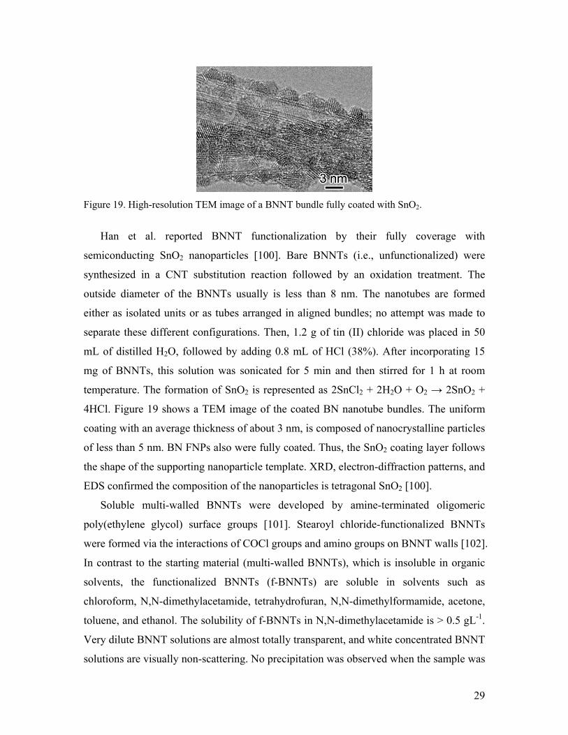
Figure 19. High-resolution TEM image of a BNNT bundle fully coated with SnO2.
Han et al. reported BNNT functionalization by their fully coverage with
semiconducting SnO2 nanoparticles [100]. Bare BNNTs (i.e., unfunctionalized) were
synthesized in a CNT substitution reaction followed by an oxidation treatment. The
outside diameter of the BNNTs usually is less than 8 nm. The nanotubes are formed
either as isolated units or as tubes arranged in aligned bundles; no attempt was made to
separate these different configurations. Then, 1.2 g of tin (II) chloride was placed in 50
mL of distilled H2O, followed by adding 0.8 mL of HCl (38%). After incorporating 15
mg of BNNTs, this solution was sonicated for 5 min and then stirred for 1 h at room
temperature. The formation of SnO2 is represented as 2SnCl2 + 2H2O + O2 → 2SnO2 +
4HCl. Figure 19 shows a TEM image of the coated BN nanotube bundles. The uniform
coating with an average thickness of about 3 nm, is composed of nanocrystalline particles
of less than 5 nm. BN FNPs also were fully coated. Thus, the SnO2 coating layer follows
the shape of the supporting nanoparticle template. XRD, electron-diffraction patterns, and
EDS confirmed the composition of the nanoparticles is tetragonal SnO2 [100].
Soluble multi-walled BNNTs were developed by amine-terminated oligomeric
poly(ethylene glycol) surface groups [101]. Stearoyl chloride-functionalized BNNTs
were formed via the interactions of COCl groups and amino groups on BNNT walls [102].
In contrast to the starting material (multi-walled BNNTs), which is insoluble in organic
solvents, the functionalized BNNTs (f-BNNTs) are soluble in solvents such as
chloroform, N,N-dimethylacetamide, tetrahydrofuran, N,N-dimethylformamide, acetone,
toluene, and ethanol. The solubility of f-BNNTs in N,N-dimethylacetamide is > 0.5 gL-1.
Very dilute BNNT solutions are almost totally transparent, and white concentrated BNNT
solutions are visually non-scattering. No precipitation was observed when the sample was

30
kept over a long time under ambient conditions. The CL and UV/Vis absorption
experiments suggest that long alkyl chains may induce drastic changes in the band
structure of BNNTs. The effects of functionalization of BNNT with NH3 and four other
aminofunctional groups, NH2CH3, NH2 CH2OCH3, NH2CH2COOH, and NH2COOH,
were investigated theoretically using density functional calculations [103]. The authors
found little changes in the electronic structure of BNNTs. However, the chemical
reactivity of the tubes reportedly was enhanced owing to the –COOH amino groups.
BNNTs were functionalized and solubilized by interaction with Lewis bases. [104],
similarly, they were functionalized with amine groups via ammonia plasma irradiation
[105].
In addition to covalent functionalization, so-called noncovalent functionalization
through wrapping BNNTs with a conjugated polymer, poly[m-phenylenevinylene-co-
(2,5-dioctoxyp-phenylenevinylene)] (PmPV) was accomplished [106]. The functionalized
BNNTs were fully soluble in many solvents. The experimental process is sufficient facile
to be scaled up. In a typical experimental run, 5 mg of PmPV was dissolved in 20 mL of
chloroform, and then 5 mg of BNNTs was added into the solution. The mixture was
sonicated over 2 h at room temperature, followed by centrifugation (2000 rpm) to remove
insoluble materials. A homogeneous solution was obtained wherein no precipitation was
observed during a long time keeping at ambient conditions. Dilute BNNT solution is
highly transparent. The PmPV-wrapped BNNTs were fully soluble in chloroform, N, N-
dimethylacetamide, tetrahydrofuran, etc., whereas they were insoluble in water, ethanol,
and similar solvents. TEM and CL characterization indicated the existence of strong π-π
interactions between BNNTs and PmPV. Functionalization also may purify BNNTs [107]
and, most importantly, tune their band structure [108].

31
Figure 20. (a) TEM image of ferritin molecules on a BNNT. (b) EDS spectrum of a ferritin-covered BNNT. Note the characteristic Fe peak peculiar to ferritin; the Cu signal originates from a TEM grid. (c) Ferritin filled in a BNNT. (Reproduced with permission from Ref. 109. Copyright 2005 American Chemical Society)
BNNTs do not absorb visible and infrared light; this property advantageously would
protect biological molecules from overheating and damage as is the case in using CNTs.
The natural affinity of a protein for BNNTs was demonstrated, i.e. proteins can be
immobilized directly on BNNTs without using a coupling reagent. To immobilize the
proteins, the dispersed BNNTs simply were stirred with dilute protein solutions for
several hours. Figure 20a demonstrates ferritin molecules (dark contrast particles)
immobilized on a BNNT and clearly illustrates the ~ 6 nm iron core of each ferritin
molecule. The amorphous apoproteins appear around the cores. All BNNTs are coated by
the ferritin molecules. EDS analyses verified the immobilization of ferritin on BNNTs;
the Fe peaks appeared after immobilization (Figure 20b). In addition, some ferritin
molecules were found inside BNNTs (Figure 20c), probably due to numerous open tip-
ends. To raise the efficiency of the immobilization process, 1-pyrenebutyric acid N-
hydroxysuccinimide ester (PAHE) functionalized BNNTs were utilized to anchor the
ferritin protein. The BNNTs and PAHE were mixed and stirred for 2 h in an organic
solvent, dimethylformamide (DMF); then the solution was filtered and repeatedly washed
with DMF to remove excess reagent. A highly aromatic pyrenyl group in PAHE, with

32
known strong π-π interactions with the basal plane of graphite and sidewalls of CNTs,
also was found to strongly interact with the sidewalls of BNNTs. Typically, BNNTs may
have profound interactions with some chemicals via π-π stacking due to the electrical
polarization phenomena induced by a BNNT’s broken symmetry. Thus, efficient
immobilization may be based upon the formation of an amide bond via the nucleophilic
substitution of N-hydroxysuccinimide by an amine group on the ferritin [109].
4. Porous BN and BN mesh
Porous solids have applications ranging from adsorbents to purification chromatographic packing
to support structures for catalytic processes. A wide variety of porous solids exist, including
zeolites, pillared clays, porous polymeric solids, and porous carbon [110]. Among them, porous
carbon, often called activated carbon, displays exceptional porosity, extended surface area,
universal and adsorption capability, and a high degree of surface reactivity. In the broadest sense,
activated carbon can be defined as an amorphous carbon-based material with a high degree of
porosity and an extended inter-particulate surface area; often the microscopic structure can be
visualized as stacks of flat aromatic sheets cross-linked randomly. Currently, it is the most
popular and economic porous solid in use [111].
h-BN, a material structurally closely related to graphite, has an attractive combination of
chemical, thermal, and electrical properties. The utility of activated carbon suggests that an
analogous “activated” BN exhibiting a high degree of porosity and an extended interparticulate
surface area might be of scientific and economic importance. The nature of the individual B-N
bonds introduces local polar character lacking in the carbon structure. Since polar sites are
considered to improve adsorption, porous BN could be a good one. Conventionally produced film
and particle forms of BN have low surface areas, rendering them relatively useless for adsorption
applications [112]. So far, several routes have been suggested for synthesizing of porous BN.
4.1 Direct pyrolyzing borazinic precursors
Narula et al. prepared porous BN from poly(2, 4, 6-borazinylamine) with surface areas
ranging from 30-50 m2/g for powders produced at 900 ºC [113]. BN aerogels formed by critical
point drying of poly(2,4,6-borazinylamine) gels and heated to 1000 ºC exhibit low density, are
highly porous, and have surface areas of ~400 m2/g [69]. Porous BN materials with surface areas
of 437-712 m2/g also were generated using similar polymeric precursors [114-116]. One example
of the methodology is as follows: A sample of (Me2NB)B2C2N3H3 (3.28 g, 17.0mmol)s was

33
dissolved in 120 mL of chlorobenzene at 23 ºC, to which (Me3-Si)2NH (2.74 g, 17.0 mmol) was
added via syringe while stirring the solution. The mixture formed a gel that containing some of
the solvent. The solvent was vacuum evaporated, and the remaining solid was vacuum-dried for
24 h. The residue (3.12 g) was treated twice with 150 mL of NH3 (1) held at ~30 ºC and left for 4-
5 h with a slow stream of N2 passing through the flask. The NH3 (l) slowly evaporated under
these conditions, during which the polymer dissolved in the NH3 (l). The resulting foamy residue
(2.7 g) was vacuum-dried for 30 min. The formed polymer was pyrolyzed in vacuo at 800 ºC or
1000 ºC in a horizontal tube furnace, with the polymer contained in a quartz or platinum crucibles
inside a quartz tube. The porous BN materials thus produced can adsorb H2, O2, CO2, CO and
CH4. Surface area and pore volume were maximized at pyrolysis temperatures of 800 ºC and
essentially eliminated at 1200 ºC. These results indicate that the pore structure of polymer-
derived boron nitride is a function of both the precursor’s polymer structure and pyrolysis
conditions [117, 118]. This demonstration of the ability to tailor BN’s pore structure and
adsorption properties by controlling these parameters is an important advance in nonoxide pre-
ceramic polymer processing.
4.2 Use of mesoporous molds
Dibandjo et al. prepared porous BN by nanocasting a hexagonally ordered mesoporous
carbon (CMK-3) or a cubic mesoporous carbon (CMK-8) with a molecular BN precursor [68, 117,
118]. CMK-3 was prepared using SBA-15 silica as a template, and sucrose as a carbon source
[117]. CMK-8 is synthesized by nanocasting Ia3d cubic silica (KIT-6) [68].
Tri(methylamino)borazine (MAB) was used as the BN precursor and prepared from 2,4,6-
trichloroborazine (HNBCl)3 (TCB), and methylamine. The material was infiltrated using 2 g of
MAB per g of carbon. Then, a ceramization step is carried out under nitrogen at 1000 ºC, yielding
a composite BN-C. The template is eliminated next via a hydrogenation reaction , leaving BN;
this step entails thermal treatment under ammonia at 1000 ºC. The resulting XRD spectrum
shows two peaks at 2θ = 26 º and 43 º, demonstrating the formation of a turbostatic phase of BN.
A small-angle diffraction peak of BN appears at 2θ = 1.22 º that is attributed the (211) reflexion
of a cubic I13d phase and the corresponding cell parameter, a = 17.7 nm. Mesoporous BN has a
specific area of 820 m2/g, a mesoporous volume of 0.32 cm3/g and a pore size distribution
centered on 4.7 nm in diameter. Similar experimental conditions were employed in preparing,
hexagonal ordered mesoporous BN with a specific surface area of 540 m2/g, a mesoporous
volume of 0.27 cm3/g, and a narrow pore-size distribution (center on 4.4 nm in diameter) starting
with tri(methyl-amino)borazine as the BN source and CMK-3 mesoporous carbon as the template.

34
(Figure 21). This work demonstrates that cubic and hexagonal ordered mesostructure of CMK-8
or CMK-3 is almost fully transferred to the BN replica [68].
Figure 21. Representative transmission electron micrograph of the boron nitride replication taken with the incident beam parallel to the [010], and the corresponding Fourier diffractogram (Reproduced with permission from Ref. 68. Copyright 2006 ELSEVIER) 4.3 Carbon-template substitution-reaction
The synthesis routes described above for generating BN with enhanced porosity typically
employ expensive and highly toxic borane-based molecular precursors, which limit their
employment for high-volume production.
An alternate method, carbon template substitution-reaction, is suitable for obtaining porous
BN [119]. It was used to prepare BN and BxCyNz nanotubes [17, 39]. CNTs and activated carbon
have high specific surface areas that reactant gases (such as boron oxide and nitrogen) readily can
reach. Hence, based on such similarities, porous BN might well be formed using porous carbon as
a template. Used porous carbon was obtained commercially from the Calgon company. The
specific surface area, total pore volume, and average pore radius of the starting material was,
respectively, 779.0 m2/g, 0.5465 cm3/g, and 14.03 Å. The substitution reaction was performed in
a horizontal, high-temperature furnace. B2O3 powder in an open graphite crucible was covered
with activated carbon and held in a flowing nitrogen atmosphere at 1580 °C for 45 min. Then,
BxCyNz, the intermediate product, was collected from the bed of porous carbon and heated in air
at 600 ºC for 30 min to remove remaining carbon and/or convert BxCyNz to pure BN [119].
Figure 22 shows TEM images for the starting material and its product. Figures 22a-c are
images of activated carbon at successively higher magnification, while Figures 22d-f have
corresponding results for the product, the BN material. At the 80 and 20 nm size scales, the BN-
based product is strikingly similar in morphology to the activated carbon template. The matrix of

35
both samples is a uniform, isotropic micro-texture. Subtle differences between the carbon starting
material and the BN-based product are apparent at high magnification, as seen in comparing
Figures 22c and 22f. Here the BN-based material shows slightly more “graphitization”, i.e., the
degree of activation of the BN system appears less than that of the activated carbon template.
Figure 22c reveals that the pores of the activated carbon to be mostly slit-shaped spaces between
twisted aromatic sheets. Small amounts of graphitic ribbons are seen in Figure 24c. A fast Fourier
transform (FFT) of the image in Figure 22c, shown as an inset, reveals broad fuzzy rings
corresponding to the largely amorphous structure of the activated carbon. From the corresponding
TEM image of Figure 22f, it is clear that the BN based product has more and larger crystalline
ribbons than the starting activated carbon. The inset of Figure 22f is the FFT of the associated
image that again evidences the fuzzy rings corresponding to significant amorphous structures of
the activated BN product, although angular structures in the FFT suggest that amorphization is
not as complete as in activated carbon. XRD measurements supported the conclusion that the BN
product has more crystalline structure than the starting activated carbon. EELS spectra also were
recorded during TEM characterization to confirm the stoichiometry of starting materials and
products. Most of the porous structures in the products are pure BN. On the other hand, a
minority of EELS spectra taken from some areas in them indicate the presence of B, N, and small
amount of C. The specific surface area, total pore volume, and average pore radius of template-
derived activated BN are, respectively, 168 m2/g, 0.27 cm3/g, and 32.2 Å.

36
Figure 22. TEM images of starting activated carbon (a-c) and product activated BN (d-f). The
insets in (c) and (f) show the FFT diffraction patterns of the corresponding high-resolution images
(Reproduced with permission from Ref. 119. Copyright 2004 American Chemical Society)
Terrones et al. used the same route to transfer spherical mesoporous MCM-48 carbon to
spherical mesoporous BN (100-400 nm o.d.) with 290 m2/g. The porous BN spheres exhibit
stable field emission properties at low-turn-on voltage (e.g., 1-1.3 V/µm) [120].
4.4 BN mesh
A highly regular mesh of h-BN with a 3 nm periodicity and a 2 nm hole size was formed by
self-assembly on a Rh(111) single crystalline surface. Two layers of mesh covered the surface
uniformly after exposing the clean Rh surface to to borazine (HBNH)3. The two layers were
offset. The formation of holes likely was driven by the lattice mismatch of the film and the Rh
substrate. This regular nanostructure exhibited excellent thermal stability and serve as a good
template to organize molecules, as was exemplified by the decoration of the mesh by C60
molecules [121].
Figure 23. Constant-current STM images of the BN nanomesh formed by high-temperature decomposition of borazine on a Rh(111) surface. (A) Large-area survey image taken with a bias voltage of Vb =-1.0 V and a tunneling current of It = 2.5 nA. Two steps on the Rh (111) surface cross the image. The black features are defects in the mesh, one of which is shown with different contrast in the inset. Brighter spots might be related to Ar bubbles in the near-surface region of the substrate. (B) High-resolution image (–2.0 V and 1.0 nA) clearly showing the presence of two layers of mesh that are offset such as to cover most of the Rh(111)’s surface. (C) Cross-sectional

37
profile along the diagonal white line in (B), indicating the presence of four different height levels within the individual unit cells. (D) High-resolution image taken with tunneling conditions (–2.0 V and 3.5 nA) that bring the tip closer to the surface. (E) Same as in (D) but with –2.0 V and 4.5 nA, showing the contrast in the bottom mesh layer. (F) High-resolution image of a region of h-BN nanomesh decorated by C60 molecules (–2.0 V and 1.5 nA). (G) Cross-sectional profile along the diagonal white line in (F), illustrating the occupancy (short arrow) or non-occupancy (long arrow) of the center hole sites by C60 molecules. (Reproduced with permission from Ref. 121. Copyright 2004 Advancing Science, Serving Society)
An atomically clean Rh(111) surface was held at 1070 K and exposed to a borazine vapor
pressure of 3×10⁻⁷ mbar inside an ultrahigh vacuum chamber. After exposure to 40 L (1 Langmuir
= 10 -6 torrs) and consecutive cooling down to room temperature, scanning tunneling microscope
(STM) images revealed a regular mesh structure (Fig. 23A). The B and N coverages on the
Rh(111) surface were quantified in situ by x-ray photoelectron spectroscopy (XPS). At does of
borazine between 40 and 360 L, a complete nanomesh film was produced and led to absolute
coverages of between 1.5 and 1.75 MLs (i.e., the nanomesh contains about 1.5 BN units per
surface Rh atom).
According to low-energy electron diffraction (LEED) data, a hexagonal atomic lattice is
deduced for the BN layer, with a lattice constant of 2.48 ± 0.05 Ǻ. The in-plane lattice constant of
the hexagonal Rh (111) is 2.69 Å. The lattice mismatch on Rh(111) is large, and the weakly
physisorbed h-BN layer appears to form with its native lattice constant of 2.50 Å. The superlattice
spots around the principal spots indicate a periodicity of 32 ± 1 Å, corresponding to a supercell of
12-by-12 Rh unit cells, or 13-by-13 h-BN unit cells. The LEED data thus would be consistent
with the formation of a coincidence lattice or a Moire´ pattern, but the STM image (Fig. 23A)
suggests that BN cells occupy only a portion of the superlattice unit cell. The STM image of Fig.
23B shows a small area of perfect nanomesh. Inside each supercell, there are four distinct gray-
scale levels (see also the line scan in Fig. 23C). The hexagonal nanomesh consists of two atomic
mesh layers with open apertures of 2.4 ± 0.2 nm in diameter in the outer layer, probably with
slightly smaller ones in the inner layer. Mesh wires, 0.9 ± 0.2 nm wide, are formed by the atomic
h-BN lattice. The periodicity of the mesh is 3.2 ± 0.2 nm, and the meshes of the two individual
layers are offset such as to cover most of the underlying metal surface. The first h-BN layer lies
essentially flat on the Rh(111), whereas the second one appears like a corrugated sheet that
follows the topography of the first. Fig 1F shows a region of nanomesh after the deposition of
roughly 1 ML of C60 molecules. The centers of the holes are either empty or occupied by one C60
molecule, which is more clearly visible in the line profile of Fig 1G.

38
5. BN mono- or few-layer sheets
Materials that have same dimensionality, but different numbers of layers also exhibit
significantly diverse physical properties. The properties of single- or double-walled
carbon nanotubes differ from those of from multi-walled ones. Graphene sheets,
comprising one atom-thick 2D layers of sp2 -bonded carbon (mono-layer), and few-
graphite-layer sheets are emerging materials with unusual properties that are promising
for nanoelectricals, including spintronics, because of the high mobility of their electrons
at room-temperature. Charge transport in graphene substantially differs from that of
conventional 2D electronic systems because of its linear-energy-dispersion relation near
the charge- neutrality point (Dirac point) in the electronic-band structure [122-125].
Hitherto, only a few routes and some experiments were reported for synthesizing and
characterizing BN mono- or few-layer sheets. These experiments are usually focusing on
depositing mono-layer (ML) or few-layer sheets on atomic flat metal surfaces. Well-
ordered h-BN layers can be grown by the thermal decomposition of borazine (B3N3H6)
on the surface of a transition metal, in most cases one with a hexagonal symmetry [121,
126-129] or on a square lattice (Ni (100)) [130]. The layers weakly interact with the
metal but are stable at high temperatures (up to 1000 K) and to air exposure. These
important features reflect the strong lateral inter-atomic bonds that play a key role in the
process of forming h-BN layers on different metal surfaces, but the geometry and the
lattice constant of the substrate make every system unique. Ultra-thin insulating films
weakly bonded to flat metal surfaces may offer interesting applications in constructing
further microelectronic devices due to the abrupt change of the electronic structure at the
interface.
Lattice-matched Ni (111) often is chosen as a substrate for depositing of ML h-BN
because the small compressive lattice mismatch of +0.4% between the two systems
favors the formation of commensurate layers. Ordered and flat terraces, one ML thick,
occur over a larger area [131-133]. These syntheses usually are performed in an ultra-
high vacuum (UHV) chambers. Auwärter et al. demonstrated one methodology: Ni(111)
single crystals were cleaned by exposing them to repeated cycles of Ar+ bombardment
(0.8 kV) to 30 L O2 and subsequent annealing to 1000 K [133]. The sample’s cleanliness

39
was verified by XPS and/or by STM. Subsequently, the Ni(111) surface was held at 1070
K and exposed to borazine that reacts under hydrogen to form a ML of stoichiometric h-
BN. Once the first ML is complete, the reaction rate drops by more than two orders-of-
magnitude. Accordingly, perfect ML of h-BN on Ni(111) can be prepared.
Fig. 24(a) shows STM pictures of the surface after the formation of a h-BN layer on
Ni(111). It displays a large area topography scan (1 nA, +100 mV) of atomically flat
terraces separated by steps of about 2 Ǻ high; the h-BN layers grow flat and perfect. The
Ni(111) and the h-BN on Ni(111) surfaces can be distinguished further by their different
behavior towards residual gases or metal vapor. In Fig. 24b is a picture with atomic
resolution from a h-BN layer on Ni(111); it was recorded at constant height with a W tip
at +4.8 mV bias voltage. Two hexagonal Bravais lattices are apparent that form a
honeycomb pattern. The observed lattice constant of 2.5±0.1 Ǻ corresponds to that of the
Ni(111) substrate (2.49 Ǻ ). These results represent a well-ordered surface with two
distinct atomic species [133].
Figure 24. STM pictures of a h-BN layer on Ni(111). (a) Large area topography scan showing atomically flat terraces separated by atomic steps. (b) The atomically resolved picture clearly reveals two hexagonal lattices with a lattice constant of 2.5±0.1 A° forming a honeycomb pattern. (Reproduced with permission from Ref. 133. Copyright 2008 ELSEVIER 1999).
For h-BN films on Rh (111), the large tensile lattice-mismatch of ~ 6.7% between the
over-layer and the substrate leads to the formation of a bilayer nanomesh with a
periodicity of 32 ± 2 Ǻ [122].
Recently, 2D h-BN sheets with few atomic-layers (more than 5 layers) were obtained
using a micromechanical cleavage method [134]. Layers of h-BN can be peeled off with
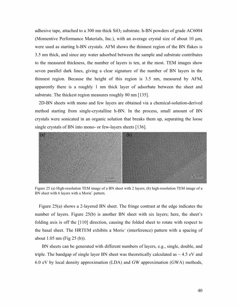
40
adhesive tape, attached to a 300 nm thick SiO2 substrate. h-BN powders of grade AC6004
(Momentive Performance Materials, Inc.), with an average crystal size of about 10 µm,
were used as starting h-BN crystals. AFM shows the thinnest region of the BN flakes is
3.5 nm thick, and since any water adsorbed between the sample and substrate contributes
to the measured thickness, the number of layers is ten, at the most. TEM images show
seven parallel dark lines, giving a clear signature of the number of BN layers in the
thinnest region. Because the height of this region is 3.5 nm, measured by AFM,
apparently there is a roughly 1 nm thick layer of adsorbate between the sheet and
substrate. The thickest region measures roughly 80 nm [135].
2D-BN sheets with mono and few layers are obtained via a chemical-solution-derived
method starting from single-crystalline h-BN. In the process, small amount of BN
crystals were sonicated in an organic solution that breaks them up, separating the loose
single crystals of BN into mono- or few-layers sheets [136].
Figure 25 (a) High-resolution TEM image of a BN sheet with 2 layers; (b) high-resolution TEM image of a BN sheet with 6 layers with a Morie´ pattern.
Figure 25(a) shows a 2-layered BN sheet. The fringe contrast at the edge indicates the
number of layers. Figure 25(b) is another BN sheet with six layers; here, the sheet’s
folding axis is off the [110] direction, causing the folded sheet to rotate with respect to
the basal sheet. The HRTEM exhibits a Morie´ (interference) pattern with a spacing of
about 1.05 nm (Fig 25 (b)).
BN sheets can be generated with different numbers of layers, e.g., single, double, and
triple. The bandgap of single layer BN sheet was theoretically calculated as ~ 4.5 eV and
6.0 eV by local density approximation (LDA) and GW approximation (GWA) methods,

41
respectively [137]. This finding signifies that a single-layer BN sheet retains the
insulating feature of BN bulk.
6 Physical properties of h-BN
Though h-BN and h-C have the same crystal structure with very close cell parameters,
their electronic properties are very distinct. The electric properties of h-C can be metallic,
semiconducting, or semi-metallic, depending on dimensionality and size, whereas h-BN
typically is an insulator whose bandgap reportedly is 5.3-5.9 eV, except for the band-gap
narrowing seen in ultra-thin nanotubes (diameter < 0.8 nm) resulting from sp3 (π)
hybridization induced by high curvature [8, 138, 139]. Multi-walled BN exhibits strong
photoluminescence at room temperature. A temporal analysis of the PL signals reveals an
underlying charge recombination process dominated by fast recombination occurring
within individual BN sheets. The slower decay process is attributed to the charge transfer
and recombination across different BN sheets and shows behavior that is consistent with
the predicted spatially indirect band gap of multi-walled BNNTs [140]. The direct
bandgap of both natural and isotopic BNNTs, which were prepared by a metal-assisted
CVD methods (50, 51) and CNT substitution reaction (14, 37), was determined by
cathodoluminescences (CL) spectra to be 5.38 eV, independent of the nanotube’s size and
isotope substitution (Figure 26) [49, 141]. At lower energies, several radiative transitions
were observed and an isotope effect was revealed. In particular, we confirmed that the
rich CL spectra between 3.0 eV – 4.2 eV reflect a phonon-electron coupling mechanism,
which is characterized by a radiative transition at 4.09 eV. FTIR spectra and density
functional theory (DFT) calculations suggest that those radiative transitions in BNNTs
might be generated by the replacement of some nitrogen atoms with oxygen [49].

42
Figure 26 Cathodoluminescences spectra taken from thick natural BN and 10BNNTs
BN materials display for better thermal, chemical and irradiation stability than its C
counterparts. Thus, BN usage is preferable for device applications wherein a high-
temperature environment or a chemical active and/or hazardous environment is expected
[37, 143].
CNTs have shown excellent thermal conductivity. Theoretical calculations and
experimental results show that thermal conductivity of BNNTs is comparable to that of
CNTs [144-147].
The stress of BNNT was measured as ~ 1.1-1.3 TPa. Thus, BNNTs might be the
stiffest insulating fibers ever known [148, 149]. Theoretical calculations demonstrated
that despite a slightly lower elastic modulus of a single-walled BNNT compared to a
single-walled CNT, the resistance of the former to thermal degradation can surpass that
of latter 150].
7. Applications
h-BN has many novel advantageous physical properties, such as electrical insulation,
high thermal and chemical stability, high thermal conductivity, and excellent mechanical
properties, all of which entail applications in many fields.
7.1. Pharmaceutical table lubricant
43
There is a wide range of lubricants available for pharmaceutical applications. Some of the
commonly used tablet lubricants are magnesium stearate (MGST), stearic acid (STAC),
glycerol esters of fatty acids, dl leucine and sodium benzoate [151]. A solid oral dosage
product must be processed with other excipients, such as “lubricants”, which decrease
friction at the interface between a tablet’s surface and the die wall during ejection to
reduce wear on punches and dies, prevent sticking to punch’s faces, improve the fluidity
and filling properties and the manufacturing efficiency of solid preparations [152]. An
ideal lubricant should reduce shear strength at the interface between the tablet and die
wall, and the coefficient of friction, and hence, the frictional force at a given load. It
should be non-toxic, chemically inert, unaffected by process variables, have no adverse
effects on the finished dosage form, and be consistent from batch to batch [153].
h-BN is an interesting compound with the potential of being incorporated as a
lubricant into tablet formulations since it is soft, lubricious, highly heat stable and an inert
material that will not react with other pharmaceutical excipients during manufacturing. It
is considered safe as a 99.9% high purity material. The first application of h-BN as a
table lubricant was carried out by Turkoglu et al. in 2005 [154]. They calculated the
lowest punch ejection force by comparing the ejection force of control batches with those
of lubricant-containing ones and evaluated h-BN as a new tablet lubricant by comparing
its properties with MGST, STAC, and glyceryl behenate (COMP). h-BN was as effective
as MGST in reducing the LPEF at 0.5–1%. Like all conventional lubricants, the higher
the concentration of h-BN, the lower the mechanical properties of tablets because of its
hydrophobic character [155]. h-BN had no significant effect on the tablet’s properties.
Moreover, comparison of other parameters, such as effect on disintegration time, and the
tablet’s crushing strength and tablet tensile strength, demonstrated that h-BN was better
than MGST. Their results showed h-BN can be used as a new lubricant in this technology.
7.2. Cosmetic materials
Cosmetic compositions usually contain components, such as metallic oxides, to
confer opacity to the composition. These components may be excellent for evening-out
skin tone, but may not be very flattering to certain types of skin. Furthermore, due to their
44
tendency to accumulate in furrows, these components actually may emphasize deeper
wrinkles and flaws rather than hide them. Previously, "soft focus" types of powders were
used in cosmetic compositions in an attempt to hide skin flaws. These materials are
spherical powders that give skin light-scattering properties. Spherical silica, polyethylene,
or polymethylmethacrylate (PMMA) operate on the principle of diffusing light incident
on the face in such a way that the overall appearance of the skin is blurred in the viewer's
eye, thereby minimizing the ability to detect lines and wrinkles [156].
Since BN is transparent, it has been used as a raw powder for cosmetics, primarily as
a particulate material in very small quantities ranging from 0.1-70 wt. % depending on
the type of cosmetic, i.e., eye-shadows, lipsticks, foundation make-up, powder, blushes,
shampoos, and conditioners. BN fillers and a host of other fillers were used in cosmetic
compositions, such as spherical silica, polymethylmethacrylate, titanium dioxide, walnut
shell powder, and mixtures thereof. These fillers may be surface-treated with lecithin,
amino acids, mineral oil, silicone oil, or various other agents, either alone or in
combination, to coat the powder’s surface, so rendering the particles hydrophobic. BN
also has been employed in diverse cosmetic compositions, from providing sun protection,
reducing the shine from oily skin, for cooling (due to its high thermal conductivity), and
affording smoothness. The size of BN filler employed in the composition of the prior art
ranges from 20 micrometers to sub-micrometers. The collapsibility of the spherical BN
particles impacts an excellent luster to the cosmetic composition. Sub-micron BN powder,
in a formulation such as a foundation, surprisingly creates the illusion of substantially
flawless skin, by blurring the appearance of wrinkles and lines on the wearer's skin while
also noticeably covering color blemishes, spots, and defects [157].
7.3. 10BNNTs for cancer therapy and diagnostics
Radiation therapy is well-established in treating cancers, and generally involves the
localized delivery of radiation to the site of a tumor. Such radiation therapy relies on the
free radical disruption of cellular DNA to destroy cancer cells in a targeted manner.
Radiation may come from a machine outside the body or from radioactive materials
implanted in the body near cancer cells. Systemic radiation therapy uses a radioactive
45
substance, such as a radiolabeled monoclonal antibody that circulates throughout the
body, and entails carefully selecting material comprising radioactive isotopes able to
deliver the desired type and amount of radiation. Radioisotopes also find use as medical
diagnostic tools. Boron Neutron Capture Therapy (BNCT) is an experimental approach to
cancer treatment that is based on a dual-step technique: Accumulation of a boron-
containing compound within a tumor and subsequent exposure to a beam of low-energy
neutrons directed at the boron-containing tumor. Subjecting boron atoms to low-energy
neutron radiation causes the boron nuclei to disintegrate into alpha particles and lithium
isotopes with a kinetic energy of 2.5 MeV; the generated energy in malignant cells
suffices to destroy them without damaging the neighboring cells. Buzatu et al. proposed
using isotopic 10BN nanostructures in BNCT. Antibody species are attached to the BN
nanostructures to enable them to target tumors. Once such BN nanostructure-antibody
composite species are near a tumor, they can be activated with transdermal neutrons, so
that the 10B atoms emit alpha particles that can destroy cancerous cells [158].
7.4. BNNT composites
Because of their exceptional morphological, electrical, thermal, mechanical and optical
(transparent for visible and infrared light) properties, BNNTs make particular promising
reinforcement materials in composites with ceramics or polymer matrices. Key issues to
address include the good dispersion of the nanotubes, the control of the nanotube/matrix
bonding, and the densification of bulk composites and thin films.
A barium calcium alumosilicate glass with a 4 wt. % of BNNT fraction was
reinforced by 90% and 35% for ambient-temperature fracture strength and fracture
toughness. Microscopic examinations of the fracture surfaces revealed that BNNTs were
responsible for these improvements [159]. Common engineering ceramics, Al2O3 and
Si3N4, loaded with 2.5–5.0 wt% BNNT fractions both became much more deformable at
high temperatures. For example, Al2O3 with 2.5 wt% of BNNT possessed a ca. 4.5 times
lower yield stress and a higher true strain-to-fracture than the untreated ceramic. Its
parameters of high-temperature super-plasticity were notably improved. By contrast,
control experiments on BN micro-powders added to these ceramics at the same fractions
showed no analogous positive effects [160].

46
Figure 27. (a) Fully transparent polymeric films containing various fractions of BNNTs in polystyrene matrices (b) TEM image of numerous straight BNNTs randomly and evenly dispersed in a polymer; and, (c) the histograms demonstrating an increase in the elastic modulus (under tensile tests) of polystyrene films after adding variable BNNT fractions dissolved in different solvents. (Reproduced with permission from Ref. 160. Copyright 2006 Materials Research Society and 2007 Wiley-VCH)
Soluble BNNTs were obtained through noncovalent tube wrapping with a polymer or
covalent functionalization. The availability of such solutions allowed researchers to
prepare high-quality, self-organized BNNT-reinforced polymer films based on
polyaniline [161] and polystyrene [162]. Tensile tests on them indicated that the elastic
modulus of the films was improved by ca. 21% when just a ca. 1 wt% soluble BNNT
fraction was employed, as illustrated in Figure 27. These BNNT composite films had
better stability to oxidation and slightly lowered glass transition temperatures than the
untreated polymers [160].
7. 5. Gas adsorption
Increasing concerns about energy and the environmental concerns call for a hydrogen
economy that entails its safe and efficient production, transportation, conversion, and
storage [163, 164]. Hydrogen storage has attracted much attention. Gas adsorption is
inherently safe and is potentially more energy-efficient than metal hydrides, compressed
gas and liquid storage. The main challenge in this field is to discover materials with a

47
reversible high hydrogen sorption capacity (e.g., the DOE’s benchmark goal of 6 wt %)
at ambient temperature and pressure. CNTs have been considered as promising materials
for hydrogen storage. Although this potential is controversial and the adsorption
mechanism in these carbon-related materials remains vague, it was demonstrated that the
hydrogen storage capacity highly correlates with the surface accessible to hydrogen [164-
166]. In many respects, BNNTs are an analogue to CNTs. Due to their dissimilar local
electronic structure, the B-N bond has ionic character that may induce an extra dipole
moment. Therefore, the stronger (de-) hydriding properties of BN are expected to be
better than those of graphite [167].
Wang et al. reported that nanostructured h-BN can absorb a concentration of
hydrogen up to 2.6 wt% after mechanically milling h-BN powders for 80 h under a
hydrogen pressure of 1.0 MPa. Furthermore, in addition to hydrogen desorption starting
at about 570 K, nitrogen desorption also was detected at about 700 K. There was no re-
crystallization, at least below 1173 K. Thus, nanostructured h-BN possesses the ability to
trap (absorb) hydrogen during milling, and desorb it at elevated temperatures. More
importantly, its (de)hydriding properties depend not only on the defective nanostructure
itself, but also on the local electronic structure near the specific defects. This information
offers a constructive perspective for designing non-carbon materials for hydrogen storage
[168].
BNNTs may absorb hydrogen at a level equal to, or even exceeding, that of CNTs.
Multi-walled BNNTs [169] and nanofibers (with open-ended edge layers) [170] were
found to adsorb 1.8 - 2.9 wt% of hydrogen under ca. 10 MPa at room temperature.
Theoretical studies show that BN can be good hydrogen-storage medium; binding energy
of hydrogen on BNNTs is increased by as much as 40% compared to that on CNTs,
which is attributed to heteropolar bonding in BN [171]. This study suggests that the
binding energy of hydrogen can be systematically increased for sp2-like bonding
nanostructure materials by modifying the sp2 bonding. Possibly layered materials of ionic
character, more ionic than BN, with a moderate substitutional doping might have
substantially large binding energy, enough for storing hydrogen at room temperatures. An
increase in specific surface area (SSA) for BNNTs may be a solution for increasing the
operating temperature and capacity for hydrogen storage. The calculated binding energy

48
of hydrogen on activated BNNTs (those having well-developed pore structures) reached
as much as 22 kJ mol–1 and thus lies in the right range for room-temperature hydrogen
storage. The most active pores for hydrogen binding were those terminated by oxygen
atoms. Additional theoretical calculations by Wu et al. [172] demonstrated that the
adsorption energy and site can be modified by the radial deformation. When the
deformation is small, H prefers to adsorb on the boron atom, which creates an acceptor
state in the gap. However, when it is large enough, H preferentially adsorbs on the
nitrogen atom in the high curvature region of the radially deformed BNNT and creates a
donor state.
BNNTs, made by CVD method using LaNi5/B mixture and nickel powders, might
store hydrogen by an electrochemical method, though capacity is low [173]. The
hydrogen desorption of non-electrochemical recombination in cyclic voltammograms,
which is considered as the slow reaction at BNNTs, suggests the possible existence of
strong chemisorption of hydrogen, and it may lead to the lower discharge capacity of
BNNTs.
7.6. Electrical nano-insulators
The electric insulating feature of BNNTs offers a promising way to prepare
electrically insulated nanocables with embedded metallic or semiconducting nanowires.
Such cables might be utilized in downsized electrical devices and complex multi-cable
circuits [76-95]. BNNTs also can enhance the field emission character of filled
semiconductors.
7.7 Ultraviolet Lasers and LED
GaN and related semiconductors have been used commercially to fabricate high-power
and blue-light laser devices [174-176]. Demand is increasing for compact ultraviolet
lasers with even shorter wavelengths as they are essential in applications such as storage,
photocatalysts, sterilization, ophthalmic surgery and nanosurgery. h-BN is a promising
material for such devices because it has a direct bandgap in the ultraviolet region. Pure h-
BN single-crystals made by a high-pressure flux method shows a stable dominant

49
luminescence peak and a series of s-like excitation absorption bands around 215 nm,
proving it to be a direct-bandgap material [177]. The laser-emission spectra for the BN
single crystal sample with well-cleaved surfaces reveal room-temperature ultraviolet
lasing at 215 nm. The longitudinal mode is enhanced, even at a flux density of 0.2
mAcm-2 and an electron-beam accelerating voltage of 20 kV. This signifies that the
threshold power is lower than 4 Wcm-2, which is of the same order as for optical lasing
for ZnO [178]. Kubota et al. developed a new synthesis route to prepare high-purity h-
BN crystals at atmospheric pressure using a nickel-molybdenum solvent. The h-BN
crystals so obtained also emitted intense 215 nm luminescence at room temperature [179].
7. 8. BN as support for catalysts
The popular materials used as supports of catalytically active phases are oxides, such as
alumina, silica, and mixture of silica-alumina. To improve stability and catalytically
activity, other materials having high thermal conductivity and thermal stability tentatively
might be employed as supports of catalytically active phases. Besides these features, BN
has other attributes, such as high surface area, hydrophobic (thus preventing moisture
condensation on its surface) and weak chemical support-active species interaction that
leads to it being a possible good catalyst. Wu et al. showed that porous BN supported Pt-
Sn catalysts were efficient catalysts for the selective hydrogenation of α, β-unsaturated
aldehyde into unsaturated alcohol [180]. Although butyraldehyde and butanol in crotonal-
dehyde hydrogenation are favorable based on thermodynamic equilibrium, the product
selectivity can be shifted to crotyl alcohol by controlling the reaction kinetics on the Pt-
Sn/BN catalysts. The yield of crotyl alcohol was as high as 38% on Pt-Sn(0.75)/BN at 80
ºC. Moreover, crotyl alcohol selectivity reached 80% at a conversion of 10% near 40 ºC.
Pd loaded -porous BN was proven to be a catalyst that could be used under hard
conditions, like methane oxidation or hydrocarbon cracking without exhibiting any
decrease in activity [181].
8. Concluding remarks

50
h-BN has been the focus of much research for many decades. BNNTs, porous BN, mono
and few-layers BN have received much more attention during recent years. Although h-
BN is less popular than to its analogous h-C, it exhibits some advanced properties and
promising applications; thus; further efforts are desired to realize its potential. This field
faces many challenges, such as the synthesis of pure single-walled BNNTs, well aligned
BNNTs, porous BN with very high specific surface area, separated mono-layer BN sheets.
Further explorations of the novel physical properties and new applications of these h-BN
nanostructures should be encouraged.

51
References 1. T. Sato, Studies on hexagonal and rhomobohedral layered boron nitrides: synthesis,
crystal growth, and transformation under high pressure, Report of National Institute for Research in Inorganic Materials, Tsukuba, Japan, 1987.
2. John J. Pouch, Samuel A. Alterovitz, Synthesis and properties of boron nitride, Aedermannsdorf, Switzerland: Trans Tech, 1990.
3. W. H. Balmain, J. Prakt. Chem. 1842, 27, 422. 4. Y. Meng, H.-K. Mao , P. J. Eng, T. P. Trainor, M. Newville, M. Y. Hu, C. Kao, J.
Shu, D. Hausermann, R. J. Hemley, The formation of sp3 bonding in compressed BN, Nature Mater. 2004, 3, 111-114.
5. W. J. Zhang, I. Bello, Y. Lifshitz, and S. T. Lee, Recent advances in cubic boron nitride deposition, MRS Bull. 2003, 184-188.
6. P. B. Mirkarimi, K. F. McCarty, and D. L. Medlin, Review of advances in cubic boron nitride film synthesis, Mater. Sci. Eng., R 1997, 21, 47-100.
7. S. Iijima, Helica microtubules of graphitic carbon, Nature, 1991, 354, 56-58. 8. A. Rubio, J. L. Corkill, and M. L. Cohen, Theory of graphitic boron-nitride nanotubes, Phys.
Rev. B, 1994, 49, 5081-5084. 9. N. G. Chopra, R. J. Luyken, K. Cherrey, V. H. Crespi, M. L. Cohen, S. G. Louie, and A. Zettl,
Boron nitride nanotubes, Science, 1995, 269, 966-967. 10. T. Ishii, T Sato, Y. Sekikawa, M. Iwata, Growth of whiskers of hexagonal boron nitride, J.
Crystal Growth, 1981, 52, 285-289. 11. X. Blasé, A. Rubio, S. G. Louie, and M. L. Cohen, Stability and band-gap constant of BN
nitride nanotubes, Europhys. Lett. 1994, 28, 335-340. 12. O. Stephan, P. M. Ajayan, C. Colliex, P. Redlich, J. M. Lanbert, and P. Bernier, and P. Lefin,
Doping graphite and carbon nanotubes structures with boron and nitrogen, Science, 1994, 266, 1683-1685.
13. K. Suenaga, C. Colliex, N. Demoncy, A. Loiseau, H. Pascard, and F. Willaime, Synthesis of nanoparticles and nanotubes with well-separated layers of boron nitride and carbon, Science, 1997, 278, 653-655.
14. W. Q. Han, J. Cumings, X. Hunag, K. Bradley, and A. Zettl, Synthesis of aligned BxCyNz nanotubes by a substitution-reaction route, Chem. Phys. Lett., 2001, 346, 368-372.
15. A. Loiseau, F. Willaime, N. Demoncy, G. Hug, and H. Pascard, Boron nitride nanotubes with reduced numbers of layers synthesized by arc discharge, Phys. Rev. Lett., 1996, 76, 4737-4740.
16. D. Golberg, Y. Bando, M. Eremets, K. Takemura, K. Kurashima, and H. Yusa, “Nanotubes in boron nitride laser heated at high pressure,” Appl. Phys. Lett. 1996, 69, 2045-2047.
17. W. Q. Han, Y. Bando, K. Kurashima, and T. Sato, “Synthesis of boron nitride nanotubes from carbon nanotubes by a substitution reaction,” Appl. Phys. Lett. 1998, 73, 3085-3087.
18. O. Louie, C. R. Jones, M. Bartlett, P. C. Gibbons, R. S. Ruoff, and W. E. Buhro, “CVD growth of boron nitride nanotubes,” Chem. Mater. 2000, 12, 1808-1810.
19. Y. Chen, J. Gerald, J. Williams, and S. Bulcock, Synthesis of boron nitride nanotubes at low temperature using reactive ball milling, Chem. Phys. Lett. 1999, 299, 260-264.
20. L. Xu, Y. Peng, Z. Meng, W. Yu, S. Zhang, X. Liu, Y. Qian, A co-pyrolysis method to boron nitride nanotubes at relative low temperature, Chem. Mater. 2003, 15, 2675-2680.
21. M. Bechelany, S. Bernard, A. Brioude, D Cornu, P. Stadelmann, C. Charcosset, K. Fiaty, P. Miele, Synthesis of boron nitride nanotubes by a template-assisted polymer thermolysis process. J. Phys. Chem. C 2007, 111, 13378-13384.

52
22. C. M. Lee, S. I. Choi, S.S. Choi, S. H. Hong, Synthesis of boron nitride nanotubes by arc-jet plasma, Current Appl. Phys. 2006, 6, 166-170.
23. J. Cumings, and A. Zettl, “Mass-production of boron nitride double-wall nanotubes and Nanococoons,” Chem. Phys. Lett. 2002, 316, 211-216.
24. M. V. P. Altoe, J. P. Sprunck, J. C. P. Gabriel, K. Bradley, Nanococoon seeds for BN nanotube growth, J. Mater. Sci. 2003, 38, 4805-4810.
25. M. Terauchi, M. Tanaka, T. Matsumoto, Y. Saito, Electron energy-loss spectroscopy study of the electronic structure of boron nitride nanotubes, J. Electron Microsc. 1998, 47, 319.
26. I. Narita, T. Oku, Synthesis of boron nitride nanotubes by using NbB2, YB6 and YB6/Ni powders, Dia. & related Mater. 2003, 12, 1912-1917.
27. M. Terrones, W.K. Hsu, H. Terrones , J.P. Zhang , S. RamoSa, J. P. Hare, R. Castlllo , K. Prassldes , A.K. Cheetham , H.W. Kroto , D.R.M. Walton, Metal particle catalysed production of nanoscale BN structures, Chem. Phys. Lett. 1996, 259, 568-573.
28. D. P. Yu, X. Sun, C. Lee, I, Bello, S. Lee, H. Gu, K. Leung , G. Zhou , Z. Dong ZF, Z. Zhang, Synthesis of boron nitride nanotubes by means of excimer laser ablation at high temperature, Appl. Phys. Lett. 1998, 72, 1966-1968.
29. R. S. Lee, J. Gavillet, M. Lamy de la Chapelle, A. Loiseau, A. Loisau, J. L. Cochon, D. Pigache, J. Thibault, F. Willaime, Catalyst-free synthesis of boron nitride single-wall nanotubes with a preferred zig-zag configuration, Phys. Rev. B, 2001, 64, 121405.
30. T. Laude, Y. Matsui, A. Marraud, B. Jouffrey, Long ropes of boron nitride nanotubes grown by a continuous laser heating, Appl. Phys. Lett. 2000, 76, 3239-3241.
31. R. Arenal, O. Stephan, J. L. Cochon, A. Loiseau, The root-growth mechanism for single-walled boron nitride nanotubes in laser vaporization technique, J. Am. Chem. Soc. 2007, 129, 16183-16189.
32. M. Cau, N. Dorval, B. Cao, B. Attal-Trétout J. L. Cochon, A. Loiseau, S. Farhat, C. D. Scott, Spatial evolutions of Co and Ni atoms during single-walled nanotubes formation: Measurements and molding, J. Nanosci. Nanotechnol. 2006, 6, 1298-1308.
33. R. Arenal, O. Stephan, A. Loiseau, C. Colliex, Nanoscale bond mapping in complex nanostructures using EELS, Microsc. Microanal. 2007, 179, 1240.
34. J. Gavillet, A. Loiseau, C. Journet, F. Willaime, F. Ducastelle, J. C. Charlier, Root-growth mechanism for single-walled carbon nanotubes, Phys. Rev. Lett. 2001, 87, 275504.
35. B. J. Wang, V. K. Kayastha, Y. K. yap, Z. fan, J. G. Lu, Z. Pan, I. N. Ivanov, A. A. Puretzky, D. Geohegan, Low temperature growth of boron nitride nanotubes on substrates, Nanolett. 2005, 5, 2528-2532.
36. H. Dai, E. Wong, Y. Lu, S. Fan, and C. M. Lieber, Synthesis and characterization of carbide nanorods, Nature, 1995, 375, 769-761.
37. W. Q. Han, S. Fan, Q. Li and Y. Hu, Synthesis of gallium nitride nanorods through a carbon nanotube-confined reaction, Science, 1997, 277, 1287-1289.
38. D. Golberg, Y. Bando, K. Kurashima, and T. Sato, Promoted synthesis of multi-walled BN nanotubes from C nanotube templates, Chem. Phys. Lett. 2000, 323, 185-191.
39. W. Q. Han, W. Mickelson, J. Cumings, and A. Zettl, Transformation of BxCyNz nanotubes to pure BN nanotubes, Appl. Phys. Lett. 2002, 81, 1110-1112.
40. D. Golberg, Y. Bando, L. Bourgeois, K. Kurashima, T. Sato, “Insights into the structure of BN nanotubes,” Appl. Phys. Lett. 2000, 77, 1979-1981.
41. W. Q. Han, L. Bourgeois, Y. Bando, K. Kurashima, and T. Sato, Formation and structure of boron nitride conical nanotubes, Appl. Phys. A, 2000, 71, 83-85.
42. L. Bourgeois, Y. Bando, W. Q. Han, T. Sato, Structure of boron nitride nanoscale cones: Order stacking of 240 ° and 300 ° disclinations. Phys. Rev. B, 2000, 61, 7686-7689.

53
43. F. F. Xu, Y. Banod, R. Ma, D. Golberg, Y. Li, M. Mitome, Formation, structure, and Structural properties of a new filamentary tubular form: Hollow conical-helix of graphitic boron nitride, J. Am. Chem. Soc. 2003, 125, 8032-8038.
44. F. L. Deepak, C. P. Vinod, K. Mukhopadhyay, A. Govindaraj, C. N. Rao, Boron nitride nanotubes and nanowires, Chem. Phys. Lett. 2002, 353, 345-352.
45. W. Q. Han, Y. Banado, K. Kurashima, and T. Sato, Formation of BN fullerene - like nanoparticles and (BN)xCy nanotubes by using carbon nanotubes as templates, Jpn. J. Appl. Phys. Part 2, 1999. 38, L755-757.
46. Y. Bando, K. Ogawak, D. Golberg, Insulating ‘nanocables’ invar Fe-Ni alloy nanorods inside BN nanotubes, Chem. Phys. Lett. 2001, 347, 349-354.
47. W. Q. Han, P. J. Todd, M. Strongin, Formation and growth mechanism of 10BN nanotubes via a carbon nanotube-substitution reaction, Appl. Phys. Lett. 2006, 89, 173103.
48. A. Yusuda, N. Kawase, F. Banhart, W. Mizutani, T. Shimizu, and H.Tokumoto, Graphitization mechanism during the carbon-nanotube formation based on the in-situ HRTEM observation, J. Phys. Chem. B 2002, 106, 1849.
49. W. Q. Han, H. G. Yu, C. Zhi, J. Wang, Z. Liu, T. Sekiguchi, Y. Bando, Isotope effect on bandgap and radiative transitions properties of boron nitride nanotubes, NanoLett. 2008, 8, 491.
50. C. Tang, Y. Bando, T. Sato, and K. Kurashima, A novel precursors for synthesis of pure boron nitride nanotubes, Chem. Commun. 2000, 1290-1291.
51. C. Zhi, Y. Bando, C. Tang, D. Golberg, Effective precursor for high yield synthesis of pure BN nanotubes, Soild State Comm. 2005, 135, 67-70.
52. C. W. Chang, A. M. Fennimore, A. Afanasiev, D. Okawa, T. Ikuno, H. Garcia, D. Y. Li, A. Majumdar, A. Isotope effect on the thermal conductivity of boron nitride nanotubesZettl. Phys. Rev. Lett. 2006, 97, 085901.
53. R. Ma, Y. Bando, T. Sato, K. Kurashima, Growth, morphology, and structure of BN nanotubes, Chem. Mater. 2001, 13, 2965-2971.
54. R. Ma, Y. Bando, T. Sato, K. Kurashima, Thin boron nitride nanotubes with unusual large inner diameters, Chem. Phys. Lett. 2001, 350, 434-440.
55. L Guo, R. N. Singh, Selective growth of boron nitride nanotubes by plasma-enhanced chemical vapor deposition at low substrate temperature, Nanotech. 2008, 19, 1-6.
56. F. Lin, C. Jus, T. Tang, P. Kang, F. Yang, Mater. Chem. Phys. Thermal-heating CVD synthesis of BN nanotubes from trimethyl borate and nitrogen gas, Mater. Chem. Phys. 2008, 107, 115-121.
57. Y. Chen, L. T. Chadderton, J. F. Gerald, and J. Willams, A solid-state process for formation Appl. Phys. Lett. 1999, 74, 2960-2962.
58. J.J. Fu, Y. N. Lu, H. Xu, K. F. Huo, X. Z. Wang, L. Li, Z. Hu, Y. Chen, The synthesis of boron nitride nanotubes by an extended vapor-liquid-solid method, Nanotech. 2004, 15, 727-730.
59. J. Yu, Y. Chen, R. Wuhrer, Z. Liu, and S. P. Ringer, In situ formation of BN nanotubes during nitriding reactions, Chem. Mater. 2005, 17, 5172-5176.
60. J. Yu, Y. Cheng, R. G. Elliman, M. Petravic, Isotopically enriched 10BN nanotubes, Adv. Mater. 2006, 18, 2157-2160.
61. L. M. Cao, X. Y. Zhang, H. Tian, Z. Zhang, and W. K. Wang, Nanotech. Boron nitride nanotube branched nanojunctions, Nanotech. 2007, 18, 1-4.
62. Z. Gan, Z. Ding, Z. Huang, X. Huang, C. Cheng, C. Tang, S. Qi, Growth of boron nitride nanotube film in situ. Appl. Phys. A, 2005, 81, 527-529.
63. T. Oku, N. Koi, K. Suganuma, R. V. Belosludov, Y. Kawazoe, Formation and atomic structure of boron nitride nanotubes with a cup-stacked structure, Solid State Comm. 2007, 143, 331-336.

54
64. N. Koi, T. Oku, M. Inoue, and K. Suganuma1, Structures and purification of boron nitride nanotubes synthesized from boron-based powders with iron particles, J. Mater. Sci. 2008, 43, 2955-2961.
65. L. Xu, Y. Peng, Z. Meng, W. Yu, S. Zhang, X. Liu, Y. Qian, A co-pyrolysis method to boron nitride nanotubes at relative low temperature, Chem. Mater. 2003, 15, 2675-2680.
66. J. Dai, L. Xu, Z. Fang, D. Sheng, Q. Guo, Z. Ren, K. Wang, Y. Qian, A convenient catalytic approach to synthesize straight boron nitride nanotubes using synergic nitrogen source, Chem. Phys. Lett., 2007, 440, 253-258.
67. X. Chen, X. Wang, J. Liu, Z. Wang, Y. Qian, A reduction-nitridation route to boron nitride nanotubes, Appl. Phys. A, 2005, 81, 1035-1037.
68. P.F. Dibandjo, F. Chassagneux, L. Bois, C. Sigala, P. Miele, Synthesis of boron nitride with a cubic mesostructure, Micropor. Mesopor. Mater. 2006, 92, 286–291.
69. D. A. Lindquist, T. T. Borek, S. J. Kramer, C. K. Narula, G. Johnston, S. Schaeffer, D. M. Smith, R. T. Paine, Formational and pore structure of boron-nitride aerogels, J. Am. Cerm. Soc. 1990, 73, 757-760.
70. R.T. Paine, C.K. Narula, Synthesis routes to boron nitride, Chem. Rev. 1990, 90, 73–91. 71. P.J. Fazen, J.S. Beck, A.T. Lynch, E.E. Remsen, L.G. Sneddon, Thermally induced borazine
dehydropolymerization reactions synthesis and ceramic conversion reaction of a new high-yield polymeric precursor to boron nitride, Chem. Mater. 1990, 2, 96–97.
72. Y. T. Wang, S. Shimada, Y. Yamamoto, N. Miyaura, Preparation of h-BN nano-tubes, -bamboos, and -fibers from borazine oligomer with alumina porous template, Mater. Res. Bull. 2008, 43, 251-256.
73. K. B. Shelimov, M. Moskovits, Composite nanostructures based on template-crown boron nitrid nanotubules, Chem. Mater. 2000, 12, 250-254.
74. M. Bechelany, S. Bernard, A. Brioude, D Cornu, P. Stadelmann, C. Charcosset, K. Fiaty, P. Miele, Synthesis of boron nitride nanotubes by a template-assisted polymer thermolysis process. J. Phys. Chem. C 2007, 111, 13378-13384.
75. X. Z. Wang, Q. Wu, Z. Hu, Y. Chen, Template-directed synthesis of boron nitride nanotubes arrays by microwave plasma chemical reaction, Electrochimica Acta, 2007, 52, 2841-2844
76. W. Q. Han, Ph. Redlich, F. Ernst, M. Rühle, Synthesizing boron nitride nanotubes filled with SiC nanowires by using carbon nanotubes as templates. Appl. Phys. Lett. 1999, 75, 1875-1877.
77. W. Q. Han, Ph. Redlich, F. Ernst, M. Rühle, Formation of (BN)xCy and BN nanotubes filled with boron carbide naaowires, Chem. Mater. 1999, 11, 3620-3623.
78. F. F. Xu, Y. Bando, D. Golberg, M. Hasegawa, M. Mitome, Phase and crystallization of encapsulated cobalt nanorods inside BN nanotubes, Acta Mater. 2004, 52, 601-603.
79. D. Golberg, Y. Bando, K. Fushimi, M. Mitome, L. Bourgeois, C. Tang, Nanoscale oxygen generators: MgO2-based fillings of BN nanotubes, J. Phys. Chem. B, 2003, 107, 8726-8729.
80. Z. G. Chen, J. Zou, F. Li, G. Liu, D. M. Tang, D. Li, C. Liu, X. Ma, H. M. Cheng, G. Q. Liu, Z. Zhang, Growth of magnetic yard-glass shaped boron nitride nanotubes with periodic iron nanoparticles, Adv. Funct. Mater. 2007, 17, 3371-3376.
81. L. Yin, Y. Bando, Y. Zhu, D. Golberg, M. Li, A two-stage route to coaxial cubic-aluminum-nitride-boron nitride composite nanotubes, Adv. Mater. 2004, 16, 929-933.
82. W. Q. Han, A. Zettl, GaN nanorods coated with pure BN, Appl. Phys. Lett. 2002, 81, 5051-5053.
83. J. Zhang, L. Zhang, F. Jiang, Z. Dai, Intensive blue-light emission from semiconductor GaN nanowires sheathed with BN layers, Chem. Phys. Lett. 2004, 383, 423-427.

55
84. H. Seo, S. Bae, J. Park, H. Yang, B. Kim, Direct synthesis of gallium nitride nanowires coated with boron carbonitride layers, J. Phys. Chem. B, 2003, 107, 6739-6742.
85. C. Tang, Y. Bando, T. Sato, K. Kurashima, Comparative studies on BN-coating on SiC and Si3N4 nanowires, J. Mater. Chem. 2002, 12, 1910-1913.
86. C. Tang, Y. Bando, D. Golberg, M. Mitome, X. Ding, S. Qi, Facile nanocoating method: From B-doped to BN coated one-dimensional nanostructures, Appl. Phys. Lett. 2004, 85, 106-108.
87. Y. Zhu, Y. Bando, D. Xue, F. Xu, D. Golberg, Insulating tubular BN sheating on semiconducting nanowires, J. Am. Chem. Soc. 2003, 125, 14226-14227.
88. Y. Zhu, Y. Bando, L. Yin, Design and fabrication of BN-sheathed ZnS Nanoarchitectures, Adv. Mater. 2004, 16, 331-334.
89. Y. Zhu, Y. Bando, R. Ma, Aluminum borate-boron nitride nanocables, Adv. Matrer. 2003, 15, 1377-1379.
90. Y. Li, P. Dorozhkin, Y. Bando, D. Golberg, Controllable modification of SiC nanowires encapsulated in BN nanotubes, Adv. Mater. 2005, 17, 545-549.
91. C. Tang, Y. Bando, T. Sato, K. Kurashima, X. Ding, Z. Gan, S. Qi, SiC and its bicrystalline nanowires with uniform BN coatings, Appl. Phys. Lett. 2002, 80, 4641-4643.
92. Z. Shen, L. He, E. Wu, Y. Fan, H. He, H. Cheng, D. Li, H. Ye, Boron nitride filled with Zirconium oxide, J. Mater. Res. 2002, 17, 2761-2764.
93. W. Q. Han, C. W. Chang, A. Zettl, Encapsulation of one-dimensional potassium halides crystals within BN nanotubes, Nanolett. 2004, 4, 1355-1357.
94. W. Q. Han, A. Zettl, Nanoclystal cleaving, Appl. Phys. Lett. 2004, 84, 2644-2645. 95. W. Mickelson, S. Aloni, W. Q. Han, J. Cumings, A. Zettl, Packing C60 in boron
nitride nanotubes, Science, 2003, 300, 467-469. 96. Y. P. Sun, K. Fu, Y. Lin, W. Hunag, Functionalized carbon nanotubes: properties and
applications, Acc. Chem. Res. 2002, 35, 1095-1104. 97. J. Chen, M. A. Hamon, H. Hui, Y. Chen, A. M. Rao, P. C. Eklund, R. C. Haddon,
Solution properties of single-walled carbon nanotubes, Science 1998, 282, 95-98. 98. K. Fu, W. Huang, Y. Lin, L. A. Riddle, D. L. Carroll, Y. P. Sun, Defunctionalization
of functionalized carbon nanotubes, Nanolett, 2001, 1, 439-441. 99. V. N. Khabashesku, W. E. Billups, J. L. Margrave, Fluorination of single-wall carbon
nanotubes and subsquently derivatization reaction, Acc. Chem. Res. 2002, 35, 188-194.
100. W. Q. Han, A. Zettl, Functionalized boron nitride nanotubes with a stannic oxide coating: A novel chemical route to full coverage, J. Am. Chem. Soc. 2003, 125, 2062-2063.
101. S. Y. Xie, W. Wang, K. A. S. Fernando, X. Wang, Y. Lin, Y. P. Sun, Solubilization of boron nitride nanotubes, Chem. Commun. 2005, 3670-3672.
102. C. Y. Zhi, Y. Bando, C. C. Tang, S. Honda, K. Sato, H. Kuwahara, D. Golberg, Covalent Functionalization: Towards soluble multiwalled boron nitride nanotubes, Angew. Chem. Int. Ed. 2005, 44, 7932-7935.
103. X. J. Wu, W. An, X. C. Zheng, Chemical functionalization of boron-nitride nanotubes with NH3 and amino functional groups, J. Am. Chem. Soc. 2006, 128, 12 001-12006.

56
104. S. Pal, S. R. C. Vivekchand, A. Govindaraj, C. N. R. Rao, Functionalization and solubilization of BN nanotubes by interaction with Lewis bases, J. Mater. Chem. 2007, 17, 450-452.
105. T. Ikuno, T. Sainsbury, D. Okawa, J. M. J. Frechet, A. Zettl. Amine-functionalized boron nitride nanotubes, Solid State Comm. 2007, 142, 643-646.
106. C. Y. Zhi, Y. Bando, C. Tang, R. Xie, T. Sekiguchi, D. Golberg, Perefectly dissolved boron nitride nanotubes due to polymer wrapping, J. Am. Chem. Soc. 2005, 127, 15996-15997.
107. C. Y. Zhi, Y. Bando, C. Tang, D. Golberg, Purification of boron nitride nanotubes through polymer wrapping, J. Phys. Chem. B 2006, 110, 1525.
108. C. Y. Zhi, Y. Bando, C. Tang, D. Golberg, Engineering of electronic structure of boron-nitride nanotubes by covalent functionalization, Phys. Rev. B 2006, 74, 153 413.
109. C. Zhi, Y. bando, C. Tang, D. Golberg, Immoblization of proteins on boron nitride nanotubes, J. Am. Chem. Soc, 2005, 127, 17144-17145.
110. S. H. Joo, S. J. Choi, L. Oh, J. Kwak, Z. Liu, O. Terasaki, R. Ryoo, Ordered nanoporous arrays of carbon supporting high dispersion of platinum nanoparticles, Nature 2001, 412, 169-172.
111. R. C. Bansal, J. Donnet, F. Stoeckli, ActiVe Carbons; Marcel Dekker, Inc.: New York and Basel, 1988.
112. J. J. Pouch, S. A. Alterovitz, Synthesis and properties of boron nitride; Aedermannsdorf: Switzerland: Materials Science forum 1990, 54, 55.
113. C. K. Narula, R. Schaeffer, R. T. Paine, A. Datye, W. F. Hammetter, Synthesis of boron-nitride ceramics from poly(borazinylamine) precursors, J. Am. Chem. Soc. 1987, 109, 5556-5557.
114. J. F. Janik, W. C. Ackerman, R. T. Paine, D. W. Hua, A. Maskara, and D. M. Smith, Boron nitride as a selective gas adsorbent, Langmuir, 1994, 10, 514-518.
115. C. K. Narula, R. Schaeffer, A. K. Datye, T. T. Borek, B. M. Rapko, R. T. Paine, Synthesis of boron-nitride ceramics from Oligomeric precursors derived from 2-(Dimethylamino)-4, 6- dichloroborazine, Chem. Mater. 1990, 2, 384-389.
116. C. K. Narula, D. A. Lindquist, M. M. Fan, T. T. Borek, E. N. Duesler, A. K. Datye, R. Schaeffer, R. T. Paine, Models and polyborazine precursors for boron-nitride ceramics, Chem. Mater. 1990, 2, 377-384.
117. P. Dibandjo, L. Bois, F. Chassagneux, D. Cornu, B. Toury, F. Babonneau, P. Miele, Synthesis of boron nitride with ordered mesostructures Adv. Mater. 2005, 17, 571-573.
118. P. Dibandjo, F. Chassagneux, L. Bois, C. Sigala, P. Miele, Comparison between SBA-15 silica and CMK-3 carbon nanocasting for mesoporous boron nitride synthesis, J. Mater. Chem. 2005, 15, 1917-1923.
119. W. Q. Han, R. Brutchey, T. d. Tilley, A. Zettl, Activated boron nitride derived from activated carbon, Nanolett, 2004, 4, 173-176.
120. M. Terrones, J. C. Charlier, A. Gloter, E. Cruz-Silva, E. Terres, Y. B. Li, A. Vinu, Z. Zanolli, J. M. Dominguez, H. Terrones, Y. Bando, D. Golberg, Experimental and theoretical studies suggesting the possibility of metallic boron nitride edges in porous nanourchins, NaonLett. 2008, 8, 1026-1032.
121. M. Corso, W. Auwärter, M. Muntwiler, A. Tamai, T. Greber, J. Osterwalder, Boron nitride nanomesh, Science, 2004, 303, 217-220.
122. K. S. Novoselov, A. K. Geim, S. V. Morozov, S. V. Dubonos, Y. Zhang, and D. Jiang, Electric field effect in atomically thin carbon films, Science, 2004, 306, 666-669.

57
123. K. S. Novoselov, A. K. Geim, S. V. Morozov, S. V. Dubonos, Y. Zhang, and D. Jiang, Two-dimesional gas of massless Dirac fermions in graphene, Nature, 2005, 438, 197-200.
124. Y. B. Zhang, Y. W. Tan, H. L. Stormer, and P. Kim, Experimental observation of the quantum hall effect and Berry’s phase in graphene, Nature, 2005, 438, 201-204.
125. Y. W. Son, M. L. Cohen, and S. Louie, Half-metallic graphene nanoribbons, Nature, 2006, 444, 347-349..
126. A. Nagashima, N. Tejima, Y. Gamou, T. Kawai, C. Oshima, Electronic-structure of monolayer hexagonal boron-nitride physisorbed on metal surfaces, Phys. Rev. Lett. 1995, 75, 3918-3921.
127. E. Rokuta, Y. Hasegawa, K. Suzuki, Y. Gamou, C. Oshima, and A. Nagashima, Phonon dispersion of an epitaxial monolayer film of hexagonal boron nitride on Ni (111), Phys. Rev. Lett. 1997, 79, 4609-4612.
128. J. W. He, D. W. Goodman, Interaction of borazin with a Re (0001) surface study by LEED, TDS, AES and ELS, Surf. Sci. 1990, 232, 138-148.
129. M. T. Paffett, R. J. Simonson, P. Papin, R. T. Paine, Borazine adsorption and decomposition at Pt (111) and Ru (001) surface, Surf. Sci. 1990, 232, 286-296.
130. R. M. Desrosiers, D. W. Greve, A. J. Gellman, Nucleation of boron nitride thin films on Ni (100), Surf. Sci. 1997, 382, 35-48.
131. A. Nagashima, N. Tejima, Y. Gamou, T. Kawai, M. Terai, C. Oshima, Electroic dispersion-relations of monolayer hexagonal boron-nitride formed on the Ni (111) surface, Phys. Rev. B, 1995, 51, 4606-4613.
132. A. Nagashima, N. Tejima, Y. Gamou, T. Kawai, C. Oshima, Electronic states of monolayer hexagonal boron nitride formed on the metal surfaces, Surf. Sci. 1996, 358, 307-311.
133. W. Auwärter, T. J. Kreutz, T Greber, XPD and STM investigation of hexagonal boron nitride on Ni (111), Surf. Sci. 1999, 429, 229-236.
134. K. S. Novoselov, D. Jiang, F. Schedin, T. J. Booth, V. V. Khotkevich, S. V. Morozov, and A. K. Geim, Two-dimensional atomic crystals, Proc. Natl. Acad. Sci. U.S.A. 2005, 102, 10451-10453.
135. D. Pacilie, J. C. Meyer, C. O. Girit, and A. Zettl, The two-dimensional phase of boron nitride: Few-atomic-layer sheets and suspended membranes, Appl. Phys. Lett., 2008, 92, 133107.
136. W. Q. Han et al. (unpublished). 137. M. Terrones, J. M. Romo-Herrera, E. Cruz-Silva, F. Lopez-Urias, E. Munoz-
Sandoval, J. J. Velazquez, H. Terrones, Y. Bando, D. Golberg, Pure and doped boron nitride nanotubes, Mater. Today, 2007, 10, 30.
138. M. Radosavljevic, J. Appenzeller, V. Derycke, R. Martel, Ph. Avouris, Electrical properties and transport in boron nitride nanotubes, Appl. Phys. Lett. 2003, 82, 4131-4133.
139. X. Bai, D. Golberg, Y. Bando, C. Zhi, C. Tang, M. Mitome, K. Kurashima, Deformation-driven electrical transport of individual boron nitride nanotubes, Nanolett. 2007, 7, 632-637.
140. J. Q. Wu. W. Q. Han, W. Walukiewicz, J. W. Ager III, W. Shan, E. E. Haller, A. Zettl, Raman Spectroscopy and Time_resolved Photoluminescence of BN and BxCyNz nanotubes. NanoLett, 2004, 4, 467-471.

58
141. C. Zhi, Y. Bando, C. Tang, D. Golberg, R. Xie, T. Sekigushi, Phonon characteristics and cathodolumininescence of boron nitride nanotubes, Appl. Phys. Lett. 2005, 86, 213100.
142. D. Golberg, Y. Bando, K. Kurashima, T. Sato, Synthesis and characterization of ropes made of BN multiwalled nanotubes, Script Mater. 2001, 44, 1561-1565.
143. D. T. Morelli, J. P. Heremans, G. A. Slack, Estimation of the isotope effect on the lattice thermal conductivity of group IV and group III-V semiconductors, Phys. Rev. B, 2002, 66, 195304.
144. C.W. Chang, W. Q. Han, A. Zettl, Thermal conductivity of B-C-N and BN nanotubes, Appl. Phys. Lett. 2005, 86, 173102.
145. C.W. Chang, W. Q. Han, A. Zettl, Thermal conductivity of B-C-N and BN nanotubes, J. Vac. Sci. Technol. B, 2005, 23, 1883-1886.
146. C. W. Chang, D. Okawa, H. Garcia, A. Majundar, Nanotube phonon waveguide, A. Zettl, Phys. Rev. Lett. 2007, 97, 045901.
147. A. Zettl, C. W. Chang, G. Begtrup, A new look at thermal properties of nanotubes, Phys. Stat. Sol. 2007, 244, 4181-4183.
148. N. G. Chopra, A. Zettl, Measurement of the elastic modulus of a multi-wall boron nitride nanotube, Solid State Comm. 1998, 105, 297-300.
149. D. Golberg, X.D. Bai, M. Mitome, C.C. Tang, C.Y. Zhi, Y. Bando, Structural peculiarities of in situ deformation of a multi-walled BN nanotube inside a high-resolution analytical transmission electron microscope, Acta mater. 2007, 55, 1293-1298.
150. T. Dumitrica, H. F. Bettinger, G. Scuseria, B. I. Yakobson, Thermodynamics of yield in boron nitride nanotubes, Phys. Rev. B. 2003, 68, 085412.
151. M.I. Baraton, T. Merle, P. Quintard and V. Lorenzelli, Surface activity of a boron nitride powder: a vibrational study, Langmuir 1993, 9, 1486–1491.
152. H. Aoshima, A. Miyagisnima, Y. Nozawa, Y. Sadzuka, T. Sonobe, Glycerin fatty acid esters as a new lubricant of tablets. Int. J. Pharm. 2005, 293, 25-34.
153. T.A. Miller and P. York, Pharmaceutical tablet lubrication, Int. J. Pharm. 1988, 41, 1-19.
154. M. Turkoglu, I. Sahin, T. San, Evaluation of hexagonal boron nitride as a new tablet lubricant, Pharm. Dev. Technol. 2005 10, 381-388.
155. T. Uğurlu, M Turkğlu, Hexagonal boron nitride as a tablet lubricant and a comparison with conventional lubricants, Inter. J. Pharmaceutics, 2008, 353, 45-51.
156. J. P. Arraudeau, M. Mellul, D. Candau, Cosmetic composition capable of blurring skin defects, U.S. Pat. No. 5,223,559, 2003.
157. M. Butts, M. Sinha, S. E. Genovese, M. Yamada, Cosmetic compositions comprising sub-micron boron nitride particles, U.S. Pat. Application #: 20070207101.
158. D. A. Buzatu, J. G. Wilkes, D. Miller, J. A. Darsey, T. Heinze, A. Biris, R. Berger, M. Diggs, Nanotubes for cancer therapy and diagnostics, US Pat. Application #: 20060067939.
159. N. P. Bansal, J. B. Hurst, S. R. Choi, Boron nitride nanotubes-reinforced glass composites, J. Am. Ceram. Soc. 2006, 89, 388-390.
160. D. Golberg, Y. Bando, C. Tang, C. Zhi, Boron nitride nanotubes, Adv. Mater. 2007, 19, 2413-2432
59
161. C. Y. Zhi, Y. Bando, C. Tang, S. Hond, K. Sato, H. Kuwahara, D. Golberg, Characteristics of boron nitride nanotube-polyaniline composites, Angew. Chem. Int. Ed. 2005, 44, 7929-7932.
162. C. Y. Zhi, Y. Bando, C. Tang, S. Honda, H. Kuwahara, D. Golberg, Boron nitride nanotubes/polystyrene, J. Mater. Res. 2006, 21, 2794-2800.
163. DOE: Roadmap on manufacturing for the hydrogen economy, 2005. 164. L. Schlapbach, A. Züttel, Hydrogen-storage materials for moobile applications,
Nature, 2001, 414, 353-358. 165. A. C. Dillon, K. M. Jones, T. A. Bekkedahl, C. H. Klang, D. S. Bethune, M. J.
Heben, Nature, 1997, 386, 377-379. 166. M. Hirscher, M Becher, M. Haluska, U. Dettlaff-Weglikowska, A. Quintel, G. S.
Duesberg, Y. M. Choi, P. Downes, M. Hulman, S. Roth, I. Stepanek, P. Bernier, Hydrogen storage in sonicated carbon materials, Appl. Phys. A, 2001, 72, 129-132.
167. A. Catellani, M. Posternak, A. Baldereschi, A. J. Freeman, Bulk and surface electronic-structure of hexagonal boron-nitride, Phys. Rev. B 1987, 36, 6105-6111.
168. P. Wang, S. Orimo, T. Matsushima, H. Fujii, and G. Majer, Hydrogen in mechanically prepared nanostructured h-BN: a critical comparison with that in nanostructured graphite, Appl. Phys. Lett. 2002, 80, 318-320,
169. R. Z. Ma, Y. Bando, H. W. Zhu, T. Sato, C. L. Xu, D. H. Wu, hydrogen uptake in boron nitride nanotubes at room temperature, J. Am. Chem. Soc. 2002, 124, 7672-7673.
170. R. Ma, Y. Bando, T Sato, D. Golberg, H. Zhu, C. Xu, D. Wu, Synthesis of boron nitride nanofibers and measuremnet of their hydrogen uptake capacity, Appl. Phys. Lett. 2002, 81, 5225-5227.
171. S. Hji, Y. Kwon, Hydrogen adsorption on boron nitride nanotubes: A path to room temperature hydrogen storage, Phys. Rev. B 2004, 69, 245407.
172. X. Wu, J. Yang, J. Hou, Q. Zhu, Deformation-induced site selectivity for hydrogen adsorption on boron nitride nanotubes, Phys. Rev. B 2004, 69, 153411.
173. X. Chen, X. P. Gao, H. Zhang, Z. Zhou, W. K. Hu, G. L. Pan, H. Y. Zhu, T. Y. yan, D. Y. Song, preparation and electrochemical hydrogen storage of boron nitride nanotubes, J. Phys. Chem. B, 2005, 109, 11525-11529.
174. S. Nakamura and G. Fasol, The Blue Laser Diode ~Springer, New York, 1997. 175. J. Pankove and T. Moustakas, Gallium Nitride (GaN), Semiconductors and
Semimetals Vol. 50, Academic, San Diego, 1998. 176. T. Taniyasu, M. Kasu, T. Makimoto, An Aluminum nitride light-emitting diode
with a wavelength of 210 nanometers, Nature, 2006, 441, 325-328. 177. K. Watanaba, T. Taniguchi, H. Kanda, Direct-bandgap properties and evidence for
ultraviolet lasing of hexagonal boron nitride single crystal, Nature Mater. 2004, 3, 404-409.
178. D. C. Reynolds, D. C. Look, B. Jogai, Optically pumped ultraviolet lasing from ZnO, Solid State Comm. 1996, 99, 873-875.
179. Y. Kubota, K. Watanaba, O. Tsuda, T. Taniguchi, Deep ultraviolet light-emitting hexagonal boron nitride synthesized at atmospheric pressure, Science, 2007, 317, 932-934.
180. J. C. S. Wu, W. C. Chen, A novel BN supported bi-metal catalyst for selective hydrogenation of crotonaldehyde, Appl. Cata. A, 2005, 289, 179-185.

60
181. G. Postole, M. Caldararu, N. I. Ionescu, B. Bonnetot, A. Auroux, C. Guimon, Boron nitride: A high potential support for combustion catalysts, Thermo. Acta, 2005, 434, 150-157.
182. W.H. thanks the grants support from the U. S. DOE under contract DE-AC02-98CH10886 and Laboratory Directed Research and Development Fund of Brookhaven National Laboratory. W. H. also thanks L. J. Wu, N. Bodzin and H. G. Yu for helps in figures’ drawing.