
Animation of Warfighting Simulations with the DEVS...
40
Animation of Warfighting Simulations with the DEVS Java Tracking Environment using MIL-STD-2525B Common Warfighting Symbology Tactical Symbols Zebulun Emerson March 02, 2009 CSE 591 Applied Project Arizona State University
Transcript of Animation of Warfighting Simulations with the DEVS...

Animation of Warfighting Simulations with the
DEVS Java Tracking Environment using
MIL-STD-2525B Common Warfighting Symbology
Tactical Symbols
Zebulun Emerson March 02, 2009
CSE 591 Applied Project Arizona State University

1 Introduction Animation is a series of frames that when played in sequence at sufficient speed presents a smoothly moving image. For this project animation refers to the display of frames that depict smooth sequential changes in Tactical Symbols location and/or direction within a Battlespace through the course of a simulation executed by the DEVSJAVA Tracking Environment.
A Tactical Symbol is defined in MIL-STD-2525B. This standard in general defines Common Warfighting Symbology (CWFS) used for Department of Defense (DOD) Command Control Communications Computers and Information (C4I) systems. There are two categories of CWFS symbols. The first category are Tactical Symbols. Tactical Symbols are used to define objects that may be pinpointed to be at one location at a given point in time. MIL-STD-2525B defines three symbology sets of Tactical Symbols: Units, Equipment, and Installations (UEI), Signals Intelligence (SIGINT), and Military Operations Other Than War (MOOTW). The hierarchies for these symbology sets are defined in the standard under Appendixes A, D, and E respectively. The second category are Tactical Graphics. Tactical Graphics are used to define objects that may be defined by a single point, line, or area. MIL-STD-2525B defines two symbology sets of Tactical Graphics: Military Operations (MO) and Meteorological & Oceanographic (METOC). The hierarchies for these symbology sets are defined in the standard under Appendixes B and C respectively. The implementation described herein only applies to the definition of Tactical Symbols. The definition of Tactical Graphics should be considered out of scope for this project.
According to MIL-STD-2525B, the Battlespace is total dynamic and fluid environment within which all mission-derived operational objectives are pursued. For this project the Battlespace is limited in dimension to locations that can be described using the Earth’s Geographic Coordinate System where the coordinate of the location’s latitude does not go above 84 degrees N or below 80 degrees S. This limitation was chosen to eliminate difficulties with map projections near the poles while still including all of the Earth’s land masses (with exception of Antarctica) as well as include all of the coordinates defined by the Universal Transverse Mercator (UTM) and Military Grid Reference System (MGRS) coordinates systems.
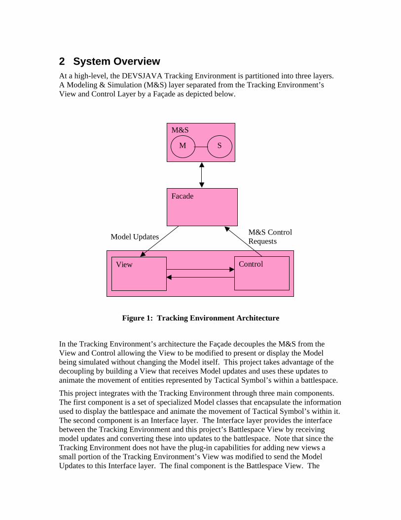
2 System Overview At a high-level, the DEVSJAVA Tracking Environment is partitioned into three layers. A Modeling & Simulation (M&S) layer separated from the Tracking Environment’s View and Control Layer by a Façade as depicted below.
M&S
M S
Facade
View Control
Model Updates M&S Control Requests
Figure 1: Tracking Environment Architecture
In the Tracking Environment’s architecture the Façade decouples the M&S from the View and Control allowing the View to be modified to present or display the Model being simulated without changing the Model itself. This project takes advantage of the decoupling by building a View that receives Model updates and uses these updates to animate the movement of entities represented by Tactical Symbol’s within a battlespace.
This project integrates with the Tracking Environment through three main components. The first component is a set of specialized Model classes that encapsulate the information used to display the battlespace and animate the movement of Tactical Symbol’s within it. The second component is an Interface layer. The Interface layer provides the interface between the Tracking Environment and this project’s Battlespace View by receiving model updates and converting these into updates to the battlespace. Note that since the Tracking Environment does not have the plug-in capabilities for adding new views a small portion of the Tracking Environment’s View was modified to send the Model Updates to this Interface layer. The final component is the Battlespace View. The

Battlespace View is responsible for displaying the battlespace and performing the animation. The following figure shows how this project is integrated with the Tracking Environment.
M&S
M S
Facade
View Control
Model Updates M&S Control Requests
Battlespace Interface
Battlespace View
Battlespace Updates
Figure 2: Project/Tracking Environment Architecture
2.1 Battlespace View
The Battlespace is the total dynamic and fluid environment within which all mission-derived operational objectives are pursued. The Battlespace View displays the Battlespace and animates the movement of entities within it through the movement of Tactical Symbols.
2.1.1 Battlespace Display
The display portion of the Battlespace View is built using layers. Each layer is responsible for displaying particular information about the Battlespace. This allows new layers to be created, added, or removed from the Battlespace View to support the specific needs of a particular application or simulation. The layers themselves are displayed over an opaque canvas in order such that each layer is painted on top of the previous as shown

below. Note that it is the responsibility of each layer to only paint those pixels that are necessary to minimize obscuring the layers below it.
Figure 3: Layers
The BattlespacePanel class provides the canvas and contains the layers that are displayed over it. The BattlespacePanel class extends the javax.swing.JPanel class allowing it to be integrated into a Java application’s display hierarchy. The BattlespacePanel communicates with the display layers through two events. The first event indicates that the visible area or dimensions of the Battlespace have changed. This may be caused by a system event such as the display size being changed or an application event such as the user zooming in/out of or panning across the Battlespace. The second event is a repaint event. A repaint event is sent when the system determines that the screen area occupied by the canvas need to be repainted or when the application determines that information being displayed by the Battlespace View has been updated warranting the display to be refreshed. Note that there is no way of knowing whether any of the above events were caused by the system or application. Also this display system does not currently keep track of what portions of the canvas need to be refreshed so it is important that each layer to repaint all visible portions when receiving a repaint event.
2.1.2 Virtual Screen Coordinates
The Battlespace defined by this project is centered around the Earth and uses the Earth’s Geographic Coordinates system to define the location of items and entities within the Battlespace.
The Geographic Coordinates system uses Latitude, Longitude, and Altitude/Depth to identify the location of an object in three-dimensional space. Latitude is the measurement in degrees between a given location, the Earth’s center and the Equator, where 0 degrees Latitude is at the Equator and 90 degrees is at the North Pole and –90 degrees is at the South Pole. Longitude is the measurement in degrees between a given

location, the Earth’s center and the Prime Meridian, where 0 degrees Longitude runs along the Prime Meridian and positive degrees extend East of the Prime Meridian until reaching 180 degrees at the antipodal of the Prime Meridian while negative degrees extend West until reaching –180 degrees at the same antipodal. Altitude and Depth on the other hand measure the distance an item is above or below the Earth’s surface. The following figure depicts the geographic coordinates systems Latitude and Longitude on the Earth’s surface. In the figure theta corresponds to degrees Latitude and lambda to degrees Longitude.
Figure 4: Geographic Coordinates
In order to display the Battlespace this project uses the concept of a Virtual Screen Coordinates that uses a transformation to translate between the Battlespace’s three-dimensional Geographic Coordinates and the Screen’s two-dimensional coordinates as shown below.

Figure 5: Virtual Screen Coordinates
The Virtual Screen Coordinates uses a transformation to convert between the two coordinates. This transform can be visualized by first wrapping a cylinder around the Earth’s Equator and projecting the Earth’s surface onto the cylinder. The cylinder is then cut from end to end and unfolded as shown in the figure below to portray a flat rectangular view of the Earth’s surface.

Figure 6: Map Projection
Since this transform distorts the Earth’s surface near the poles anything above 84˚ N or below 80˚ S are clipped. The choice of 84˚ N and 80˚ S was made because these extremes have a minimal amount of distortion, excludes very few portions of the Earth

were mission derived operations may be performed, are compatible with most mapping systems, and fits the dimensions of the UTM and MGRS coordinates systems.
Once the Earth’s surface has been projected onto a flat rectangle the transformation from 3D to 2D is completed by collapsing the altitude/depth dimension.
Now that the Geographic Coordinates have been converted to a two-dimensional rectangle the final step is to perform a translation from degrees Longitude and Latitude to the screens width and height. For this translation the top left corner of the screen is at coordinate (0,0), which corresponds to the North West most visible Geographic Coordinate as shown in the figure below.
Figure 7: Latitude/Longitude to Screen Translation

2.1.3 Animation
Animation of the Battlespace View is achieved through a mechanism for controlling the repaint operations of the View. In the DEVS Java Tracking Environment model updates from the M&S simulation are delivered to the Battlespace View through the Façade. When the Battlespace View is updated a separate repaint thread is notified. When the Battlespace View does not need repainting the repaint thread is idle. After receiving notification the repaint thread initiates the action of repainting the Battlespace View. Upon completion of performing the repaint action the repaint thread checks to see if the Battlespace View has received further updates and needs repainting. If not the repaint thread goes idle. Is it does then the repaint thread checks to see how much time has elapsed since the last repaint action. If the time is greater than the Battlespace Views desired max frame rate then the repaint thread issues the repaint action immediately. If the time is less then the repaint thread waits before issuing the next repaint action so that the elapsed time between consecutive repaint actions don’t exceed the desired max frame rate.
Using the above mechanism for generating the animation frames allows the animation to track the simulation while controlling the frame rate so that frames are only generated when the Battlespace has been updated while limiting the frame rate so that resources aren’t wasted rendering frames that are not perceivable by the user during high times when the Battlespace is receiving a rapid number of updates.
From a threading perspective there are three threads that are involved in the M&S simulation and animation of the Battlespace. The first thread is in charge of executing the M&S simulation. Model updates are sent through the Façade layer are handled by AWT Event thread. The AWT Event thread receives the model updates, updates the Battlespace, notifies the repaint thread that the Battlespace needs to be repainted, and performs the repainting of the Battlespace. The repaint thread receives notifications that the Battlespace needs to be repainted and notifies the AWT Event thread when to repaint the Battlespace based on the mechanisms used to control the frame rate of the animation as described above. The figure below depicts the threads, events and actions involved in animating the Battlespace.

M&S Simulation
Queue Event
Model Update
Event Type
Deque
Update Battlespace
Model Update
Repaint Battlespace
Paint Event
Repaint Thread
Repaint Request
Repaint Request
Real Time Display ThreadAWT Event ThreadM&S Thread
Figure 8: Animation Threading
2.2 Tactical Symbols
Tactical Symbols as defined in MIL-STD-2525B are comprised of a symbol indicator and modifiers. The symbol indicator has a frame and icon. The frame is a geometric border that defines the warfighting object’s affiliation, battle dimension, and status. The icon is bordered by the frame and is a graphical and or textual representation of the warfighting object. The tactical symbol’s modifiers may be either graphical or textual and are displayed relative to the symbol’s frame.
The following figure depicts the layout of a Tactical Symbol’s frame, icon, and modifiers.
A
E/F
G
H
M
J/K/L/N/P
W
X/Y
V
T
Z R/AG
ABB/C/D/A
AA
Q (ground)
Q (all other domains)
Figure 9: Tactical Symbol Layout

In the above figure the letters are field IDs used to identify each possible modifier. The following table describes each modifier and defines which modifiers apply to each of the 5 possible types of Tactical Symbols: Units, Equipment, Installations, Signals Intelligence (SIGINT), and Military Operations Other Than War (MOOTW). In the following table: the “Field ID” column contains the modifier ID, the “Name” column contains the name of the modifier, the “Description” column contains the description of the modifier, and the “U”, “E”, “I”, “SI”, and “M” columns are for Units, Equipment, Installations, SIGINT, and MOOTW respectively. These last five columns contain: a ‘G’ or a number if the modifier is valid and a ‘-‘ if the modifier is not valid for the respective symbol type. An entry of ‘G’ indicates that the modifier is graphical and a number indicates that the modifier is text. If the modifier is text the number specifies the maximum length of the text.
Tactical Symbol Fields
Field ID Name Description U E I SI M
A Symbol Indicator
The center of a Tactical Symbol that is comprised of an icon and a frame.
G G G G G
B Echelon A graphic modifier that indicates command level. G - - - G
C Quantity A text modifier that identifies the number of items present.
- 9 - - -
D Task Force Indicator
A graphic modifier that identifies an object as a task force.
G - - - G
E Frame Shape Modifier
A graphic modifier that displays affiliation, battle dimension, or exercise description.
G G G - G
F Reinforced or Reduced
A text modifier that displays “(+)” for reinforced, “(-)” for reduced, or “(±)” for reinforced and reduced.
3 - - - 3
G Staff Comments
A text modifier: contents are application specific. 20 20 20 20 20
H Additional Information
A text modifier: contents are application specific. 20 20 20 20 20
J Evaluation Rating
A text modifier that uses one letter to indicate reliability and one number to indicate credibility rating.
Reliability Ratings: A – Completely Reliable B – Usually Reliable C – Fairly Reliable D – Not Usually Reliable E – Unreliable F – Reliability Cannot Be Judged
Credibility Ratings: 1 – Confirmed By Other Sources
2 2 2 2 2

Tactical Symbol Fields
Field ID Name Description U E I SI M 2 – Probably True 3 – Possibly True 4 – Doubtfully True 5 – Improbable 6 – Truth Cannot Be Judged
K Combat Effectiveness
A text modifier indicating effectiveness or capability.
5 - 5 - 5
L Signature Equipment
A text modifier for hostile equipment that displays a “!” to indicate that it has a detectable electronic signature.
- 1 - 1 -
M Higher Formation
A text modifier that indicates the number or title of higher echelon command.
21 - - 21 -
N Hostile (Enemy)
A text modifier for hostile equipment that displays “ENY” to further denote that it’s affiliation.
- 3 - - -
P IFF/SIF A text modifier displaying IFF/SIF identification modes and codes.
5 5 5 - 5
Q Direction of Movement
A graphic modifier that indicates the direction of movement for the warfighting object represented by the symbol.
G G G - G
R Mobility A graphic modifier that depicts the mobility of an object.
- G - - -
R2 SIGINT Mobility
A text modifier indicating the mobility of a SIGINT object. The following are the valid values for this field.
M – Mobile S – Static U – Uncertain
- - - 1 -
S Headquarters Staff / Offset Location
Headquarters Staff: A graphic modifier that identifies an object as a headquarters.
Offset Location: A graphic modifier used to indicate the location of an object when displaying it away from its actual location.
G G G - G
T Unique Designation
A text modifier that uniquely identifies a particular symbol.
21 21 21 21 21
V Type A text modifier that indicates the type of equipment. - 24 - 24 -
W Date/Time Group (DTG)
A text modifier that displays Date/Time Group. The format for DTG is DDHHMMSSZMONYY where:
DD – Day of the Month HH – Hour of the Day (using 24 hr clock) MM – Minute SS – Second Z – Time Zone (using single letter military
code for time zone)
20 20 20 20 20

Tactical Symbol Fields
Field ID Name Description U E I SI M MON – Three Letter Abbreviation for the
Month YY – Year
X Altitude / Depth
A text modifier that displays the altitude portion of GPS, flight level, depth, or height of an object.
6 6 6 - 6
Y Location A text modifier that displays location as latitude and longitude.
19 19 19 19 19
Z Speed A text modifier that displays velocity. 8 8 8 - 8
AA Special C2 HQ
A text modifier that displays the name of Special C2 HQ.
9 - - - 9
AB Feint / Dummy
A graphic modifier that identifies an object that is an offensive or defensive unit used to draw the enemy’s attention aware from an area or main attack.
G G G - G
AC Installation A graphic modifier used to denote a symbol as an installation.
G G G - G
AD Platform Type
ELNOT or CENOT - - - 6 -
AE Equipment Teardown Time
A text modifier that displays the time, in minutes, that it takes to teardown equipment.
- - - 3 -
AF Common Identifier
A text modifier that displays the common name for an object.
- - - 12 -
AG Auxiliary Equipment
A graphic modifier that indicates the presence of a towed sonar array.
- G - - -
AH Area of Uncertainty
A graphic modifier that indicates the area where an object is most likely to be.
G G G - G
AI Dead Reckoning Trailer
A graphic modifier used to identify where an object should be located at based last reported course and speed.
G G G - G
AJ Speed Leader A graphic modifier that an object’s speed and direction of movement.
G G G - G
AK Pairing Line A graphic modifier that connects two objects. G G G - G
The following table shows the Tactical Symbol frames by battle dimension and affiliation. Note that although the “Frame Shape Modifier” is presented in the above table as a modifier it is considered part of the frame. The Frame Shape Modifier for each frame is shown in the table below and is always shown with the frame. The only exception to this rule is with SIGINT Tactical Symbols that do not display the Frame Shape Modifier. Also some of the frames below are shown with text in the center where the symbol’s icon is usually displayed. This text is considered part of the frame and is displayed in the place of the symbol’s icon. Finally the frames for battle dimension

Installation frames are depicted “Installation” modifier. This modifier is not part of the frame, but is shown because it is always shown with the frame when a symbol is of battle dimension Installation.
Tactical Symbol Frames Battle
Dimension
Affiliation
Ground
Unknown Space Air Units Equipment Installation Sea
Surface Subsurface
SOF (Special
Operation Forces)
Unknown
Pending
Friend
Neutral
Hostile
Assumed Friend
Suspect
Exercise Unknown
Exercise Pending
Exercise Friend
N/A
Exercise Neutral
N/A
Exercise Assumed Friend
N/A
Exercise Joker
N/A
Exercise Faker
N/A
In addition to the modifiers and framing shown above a Tactical Symbol has a number of display options that may be modified by the application to determine what parts of the

Tactical Symbol are displayed. The options are: frame on, fill on, and icon on. These options are used to used to turn on/off the display of the symbol’s frame, fill, or icon. The following table shows how the symbol indicator is displayed in given the valid combinations of these settings.
Tactical Symbol Display Options
Frame Fill Icon Display Examples
On On On
On Off On
On Off Off
Off Off On
Off On Off
Off Off Off
The following table contains the available values for the echelon modifier and depicts examples of how each of these values are displayed.
Echelon Modifier
Echelon Description Display Examples
Team / Crew
Squad
Section

Echelon Modifier
Echelon Description Display Examples
Platoon / Detachment
Company / Battery / Troop
Battalion / Squadron
Regiment / Group
Brigade
Division
Corps
Army
Army Group / Front
Region
The following table contains the available values for the mobility modifier and depicts examples of how each of these values are displayed.
Mobility Modifier
Mobility Display Examples

Mobility Modifier
Mobility Display Examples
Wheeled (Limited Cross Country)
Wheeled (Cross Country)
Tracked
Wheeled and Tracked
Combination
Towed
Railway
Over Snow
Sled
Pack Animals
Barge
Amphibious
The following table contains the available values for the auxiliary equipment modifier and depicts examples of how each of these values are displayed.
Auxiliary Equipment Modifier
Auxiliary Equipment Display Examples

Auxiliary Equipment Modifier
Auxiliary Equipment Display Examples
Towed Sonar Array (Short)
Towed Sonar Array (Long)
The following figure depicts the remaining graphical modifiers that are not shown in the above tables.
Figure 10: Other Graphic Modifiers
In addition to the modifiers described above a Tactical Symbol may be displayed to show that the symbol’s is being displayed at the present location or the planned, anticipated, suspected, or on-order-to location of the entity being represented by the symbol. For symbols with a frame this is shown by displaying the frame with a solid line if is at the present location or a dashed line if its at the planned, anticipated, suspected, or on-order-to location. For symbols that are not framed the symbol’s icon is displayed using a solid or dashed line respectively. Note that the standard does not define what to do if the symbol’s icon is not line based (i.e. a solid shape or text). For these icons this project displays them the same regardless or the symbol’s location is the present or planned, anticipated, suspected, or on-order-to location. The following table shows examples of Tactical Symbols being displayed with these options.
Tactical Symbol Status
Status Framed Example Unframed Example

Tactical Symbol Status
Status Framed Example Unframed Example
present location
planned, anticipated, suspected, or on-order-to location
2.2.1 Units, Equipment, and Installations (UEI)
Tactical Symbol’s of type Units, Equipment, and Installations are defined in Appendix A of MIL-STD-2525B. The UEI Tactical Symbol’s defined in this standard segregates the symbol’s by battle dimension. Unfortunately it does not identify which symbol’s are of type Unit, Equipment, or Installation. In some cases it is fairly obvious as to what type a symbol is intended to be. For example symbols of battle dimension Ground Unit, Ground Equipment, and Ground Installation appear to be intended of type Unit, Equipment, and Installation respectively. Also symbol’s for weapons such as a mine or missile by process of elimination can only be considered Equipment. However, other symbols such as a fighter plane of battle dimension air could be interpreted as equipment or units depending on its application. As a result this API provides for a default symbol type based on the most likely use, but also allows the application to determine the symbol type to allow for different interpretations of a given UEI symbol.
The following are examples of Unit, Equipment, and Installation Tactical Symbols.
Figure 11: Unit Tactical Symbol
Figure 12: Equipment Tactical Symbol

Figure 13: Installation Tactical Symbol
2.2.2 Signals Intelligence (SIGINT)
Tactical Symbol’s of type SIGINT are defined in Appendix D of MIL-STD-2525B. The following is an example of a SIGINT Tactical Symbol.
Figure 14: SIGINT Tactical Symbol
2.2.3 Military Operations Other Than War (MOOTW) Tactical Symbol’s of type MOOTW are defined in Appendix E of MIL-STD-2525B. The following is an example of a MOOTW Tactical Symbol.
Figure 15: MOOTW Tactical Symbol

3 Referenced Documents
Referenced Documents
Title Version Revision Date
MIL-STD-2525 w/ Change 1 B July 1, 2005

4 Software Summary
4.1 Software Application
The software generated for this project contains an API used to generate and display the Tactical Symbol’s defined in MIL-STD-2525B, the ability to display a battlespace and animate the movement of Tactical Symbol’s within it and hooks for integrated with DEVS Java Tracking Environment. In addition to this software this project also contains a standalone GUI that is intended to aid the user in browsing the available Tactical Symbol defined in the MIL-STD-2525B’s symbology sets for UEI, SIGINT, and MOOTW as well as navigate the Battlespace View without having to view it through the DEVS Java Tracking Environment.
4.2 Software Inventory The project inventory is depicted in the following figure and the contents of the root directory and subdirectors is defined in the following subsections. Legend: This Project’s Inventory CSE 591 Specific Code Modified DEVS Java
Tracking Environment Source Code
../cwfs src milstd2525b cwfs frame icon uei sigint mootw geo test view devs model tracking_env project plugin devs classes manifest distribution

javaDocs documentation
Figure 16: Software Inventory
4.2.1 ../cwfs
The root directory for this project. This directory contains the directories for this project’s source files, compiled class files, documentation, and other files needed to build, distribute the project and test this project.
4.2.1.1 ../cwfs/src
The ../cwfs/src directory contains the Java source files and packages that make up this project as well as the software used to test this project.
4.2.1.2 ../cwfs/src/milstd2525b
The ../cwfs/src/milstd2525b directory is the directory for the milstd2525b package and contains the subpackages and source code that is strictly part of this project.
4.2.1.3 ../cwfs/src/project
The ../cwfs/src/project directory is the directory for the project package which contains the subpackages and source code for the M&S project originally developed in CSE 591, “Introduction to Modeling & Simulation”. This project has since then been modified to be executed by the DEVS Java Tracking Environment and adapted to use this project’s animation capabilities.
4.2.1.4 ../cwfs/src/plugin
The ../cwfs/src/plugin directory is the directory for the plugin package which contains the source code for additional classes used to modify various views within the DEVS Java Tracking Environment to display information specific to models in the “project” package.
4.2.1.5 ../cwfs/src/devs
The ../cwfs/src/devs directory is the directory for the devs package which contains the subpackages and source code for the DEVS Java Tracking Environment. Note that this is the version of the Tracking Environment that has been modified to display this project’s Battlespace View.
4.2.1.6 ../cwfs/classes The ../cwfs/classes directory contains the .class files generated when the Java source files are compiled. Note that if this directory does not exist it will be created when the source files are built.

4.2.1.7 ../cwfs/manifest
The ../cwfs/manifest directory contains the manifest file(s) used in the JAR file(s) build in the ../cwfs/distribution directory.
4.2.1.8 ../cwfs/docs
The ../cwfs/docs directory contains the JavaDocs for this project’s source files.
4.2.1.9 ../cwfs/distribution
The ../cwfs/distribution directory is the target location when generating this project’s executable JAR file(s).
4.2.1.10 ../cwfs/javaDocs
The ../cwfs/javaDocs directory is the target location for this project’s source codes Java Docs.
4.2.1.11 ../cwfs/documentation
The ../cwfs/documentation directory is the location of this project’s documentation including this document.
4.3 Building the Software
The software project includes a build.xml file in the ../cwfs/src directory. The build.xml file is used by Another Neat Tool (ANT) to build the project.
ANT is distributed by the Apache Group. More information about or to download ANT go to http://ant.apache.org.
The following table defines the applicable targets in the build.xml file used to build the project.
ANT Build Targets
Target Name Description
clean Cleans the compiled .class and build .jar files for this project.
init Initializes the directories for compiling the .class and building .jar files for this project.
compile Compiled the project’s .class files.
jar Builds the project’s .jar file(s).
docs Builds the project’s JavaDocs.

4.4 Software Environment This project was developed with Java version 1.6, but should be fully back compatible to version 1.4 and forward compatible for future foreseeable versions.
5 Detailed Design
5.1 Battlespace Interface
This project interfaces with the DEVS JAVA Tracking Environment in two main areas. The first is a set of specializations of the DEVS JAVA Tracking Environments digraph and atomic classes. These specializations contain the specific information used by this project’s view to create and update the display of Tactical Symbol’s in the View of the Battlespace. The first specialization is the ViewableBattlespace which extends digraph and contains the information used by the Battlespace View to determine the dimension of the Battlespace. The second specialization is the ViewableTacticalSymbol which extends atomic and contains the information used by the Battlespace View display Tactical Symbols in the Battlespace. The ViewableTacticalSymbol itself is also specialized to handle the five types of Tactical Symbols: Unit, Equipment, Installation, SIGINT, and MOOTW.
The second area this project interfaces with the DEVS JAVA Tracking Environment is with the object that receives model updates from the Façade and in turn updates the Battlespace View. In order to do this the DEVS JAVA Tracking Environment devs.trackingEnv.view.View and devs.façade.bridge.modeling.FModel classes where modified. The View class is the DEVS JAVA Tracking Environment’s class was modified to add the Battlespace View to the display hierarchy and send model updates to the to this view. The FModel class is a class used by the Façade to bridge the M&S with the View and Control portions of the Tracking Environment. This class was modified to give the Battlespace View direct access to the underlying DEVS model allowing this project to access the specialized Viewable classes described above.
The figure below shows the class diagram that shows the interfaces between this project and the DEVS JAVA Tracking Environment. Note that the Tracking Environment classes are shown in mauve and this projects classes are shown in yellow.

ViewableBattlespace(from model)
ViewableTacticalSymbol(from model)
ViewableUnit(from model)
ViewableEquipment(from model)
ViewableInstallation(from model)
ViewableSIGINT(from model)
ViewableMOOTW(from model)
View(from view)
BattlespaceView(from tracking_env)
atomic(from modeling)
digraph(from modeling)
Model Updates
Figure 17: Tracking Environment/Battlespace View
5.2 Battlespace View
The core of the Battlespace View is the BattlespacePanel class. The BattlespacePanel class extends the javax.swing.JPanel and provides the canvas on which the Battlespace is displayed. The BattlespacePanel contains navigation controls encapsulated by the NavigationControls class and are used by the BattlespacePanel to allow the user to zoom in/out and pan throughout the Battlespace. The BattlespacePanel also contains multiple DisplayLayers used to display various aspects of the Battlespace. Both the DisplayLayers and BattlespacePanel use VirtualScreenCoordinates for translating between the Battlespace’s Geographic Coordinates and the Screen coordinates on which the Battlespace is displayed. The DisplayLayer class itself is an abstract base class. This class is subclassed as needed to display various aspects of the Battlespace. Finally the Battlespace View uses a ReadltimeDisplayThread class that extends the java.lang.Thread class and is used to support the repaint mechanism used to animate the Battlespace View. The class diagram of the Battlespace View is shown below.

GeographicGridDisplayLayer ManeuverNetworkDisplayLayer TacticalSymbolDisplayLayer
VirtualScreenCoordinates
RealtimeDisplayThread
NavigationControls
DisplayLayer
BattlespacePanel
BattlespaceView(from tracking_env)
Battlespace Updates
Figure 18: Battlespace Panel Class Diagram
5.3 Tactical Symbols
The implementation of the MIL-STD-2525b Tactical Symbols is encapsulated within the TacticalSymbol class. This class has the ability to display all aspects of a TacticalSymbol with exception to the Area Of Uncertainty, Dead Reckoning Trailer, and Pairing Line modifiers. Since these modifiers require knowledge of the Battlespace View, in particular the translation between meters and pixels as well as the display location of other TacticalSymbols. Although the TacticalSymbol class encapsulates the information used to display these modifiers the display of them is left up to the TacticalSymbolDisplayLayer. In order to aid in the display of a Tactical Symbol the TacticalSymbol class uses the SymbolProperties class and contains a TacticalSymbolFrame and TacticalSymbolIcon. The SymbolProperties class contains static functions and data members for specifying details such as Tactical Symbol size, fonts, and colors. The TacticalSymbolFrame and TacticalSymbolIcon classes are contained by the symbol and used to display its frame and icon.

SymbolProperties
TacticalSymbolFrame TacticalSymbolIcon
TacticalSymbol
Figure 19: Tactical Symbol Class
The TacticalSymbol class itself is abstract and access to the data members used to specify the values of the TacticalSymbol’s modifiers are private and the accessors and mutators to these data members are protected. It is up to the TacticalSymbol’s subclasses to provide public accessors and mutators to those modifiers are valid for the specific type of Tactical Symbol. The TacticalSymbol has five subclasses for each type of Tactical Symbol, Unit, Equipment, Installation, SIGINT, and MOOTW, as shown in the figure below.
TacticalSymbol
UnitTacticalSymbol EquipmentTacticalSymbol InstallationTacticalSymbol SIGINTTacticalSymbol MOOTWTacticalSymbol
Figure 20: Tactical Symbol Class Hierarchy
MIL-STD-2525B defines over 900 Unit, Equipment, and Installation Tactical Symbols, over 50 SIGINT Tactical Symbols, and approximately 35 MOOTW Tactical Symbols. The standard uniquely identifies each of these symbol’s with a Symbol ID Code. The Symbol ID Code is 15 characters in length and contains information that specify a subsection of the symbol’s modifiers as well as information needed to uniquely identify a specific symbol. The TacticalSymbolFactory class is used to create TacticalSymbol’s based off of a SymbolIDCode. Note that since each type of symbol UEI, SIGINT, and MOOTW use different decoding schemes. The SymbolIDCode class is the base class for decoding and encapsulating the information about a Symbol ID Code. This class is subclassed to handle the variations between each symbol types decoding scheme. The SymbolIDCode class is also used by the application and TacticalSymbolFactory to specify what symbol to create. The following figure shows the class diagram for the TacticalSymbolFactory and SymbolIDCode class hierarchy.

TacticalSymbolTacticalSymbolFactory
SymbolIDCode
UEISymbolIDCode SIGINTSymbolIDCode MOOTWSymbolIDCode
Figure 21: Tactical Symbol Factory Class

6 Program Reference Guide
6.1 MIL-STD-2525B Tactical Symbols
This project provides an application for selecting and displaying Tactical Symbol’s in the Battlespace. The application allows the user to select any symbol defined in one of the MIL-STD-2525B’s three symbology sets (UEI, SIGINT, MOOTW), set the symbol’s affiliation, display options, status, and set the value of the symbol’s modifiers and view the resulting symbol in the Battlespace.
This application is build by executing ant with the default target from the project’s src directory. Once built the application is started by running the executable jar cwfs.jar located in the project’s distribution directory.
Once started the application displays a GUI. On the left side of the GUI are the controls for selecting a Tactical Symbol and setting it’s affiliation, display options, and status. The center of the GUI displays the selected symbol in the Battlespace and the right side of the GUI displays the controls for setting the values for each of the symbol’s modifiers. An example of this application’s GUI is shown in the figure below.
Figure 22: MIL-STD-2525B Tactical Symbols Application
A Tactical Symbol is selected by expanding desired branches of the symbology hierarchy tree and single clicking on the desired Tactical Symbol in the tree. Note that levels within the hierarchy that are associated with a symbol have an icon of the symbol displayed next to it while levels that are not are displayed with a folder icon. Also not all of the Tactical Symbol’s icons have been implemented if the symbol has an icon and it is

implemented then the icon will be displayed. However, if the icon has not been implemented then an octagon will be displayed in place of the icon. The following figure is an example of the symbology hierarchy tree.
Figure 23: Tactical Symbol Selection
Below the symbology hierarchy tree are a set of controls for changing the symbol’s display options, frame, icon, and fill on or off. Note that some symbols are always framed, some are never framed, and others may be framed or unframed. The controls for turning these options on or off will be disabled if they cannot be changed for the selected symbol. An example of these controls are shown in the figure below.
Figure 24: Tactical Symbol Display Options
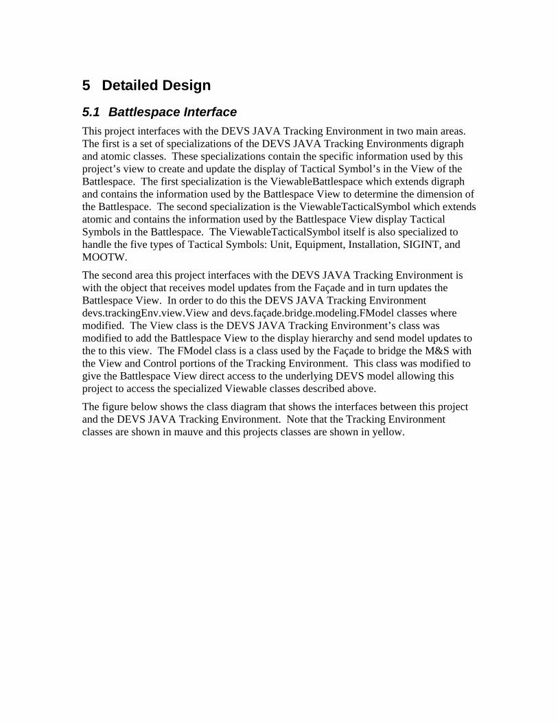
Below the Display Options controls are another set of controls for changing the symbol’s status: present or planned, anticipated, suspected, or on order to. An example of these controls are shown in the figure below.
Figure 25: Tactical Symbol Status
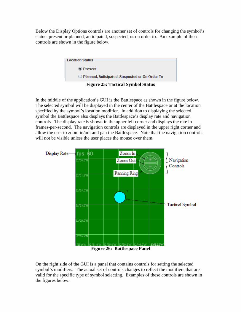
In the middle of the application’s GUI is the Battlespace as shown in the figure below. The selected symbol will be displayed in the center of the Battlespace or at the location specified by the symbol’s location modifier. In addition to displaying the selected symbol the Battlespace also displays the Battlespace’s display rate and navigation controls. The display rate is shown in the upper left corner and displays the rate in frames-per-second. The navigation controls are displayed in the upper right corner and allow the user to zoom in/out and pan the Battlespace. Note that the navigation controls will not be visible unless the user places the mouse over them.
Figure 26: Battlespace Panel
On the right side of the GUI is a panel that contains controls for setting the selected symbol’s modifiers. The actual set of controls changes to reflect the modifiers that are valid for the specific type of symbol selecting. Examples of these controls are shown in the figures below.

Figure 27: Unit Tactical Symbol Modifiers
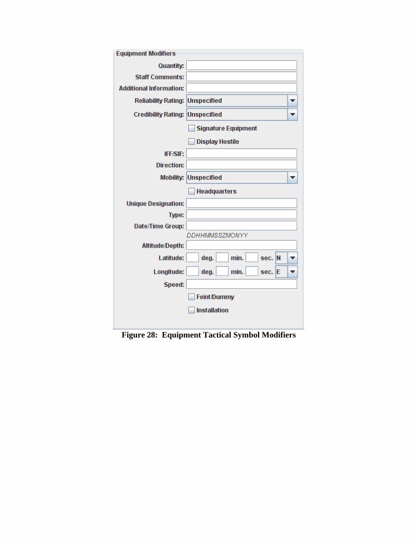
Figure 28: Equipment Tactical Symbol Modifiers

Figure 29: Installation Tactical Symbol Modifiers
Figure 30: SIGINT Tactical Symbol Modifiers

Figure 31: MOOTW Tactical Symbol Modifiers
6.2 Tracking Environment Example
In order to test this project with the DEVS JAVA Tracking Environment the semester project from CSE 591 “Introduction to Modeling & Simulation” to execute under the Tracking Environment and use the Viewable model classes. Note that the version of the DEVS JAVA Tracking Environment used for this example contains the changes mentioned here-in as well as changes to the DEVS JAVA Tracking Environments control to allow the input of stochastic data.
The modified Tracking Environment and semester project is built by executing ant with the default target from the project’s src directory. Once built the Tracking Environment is started by running the executable jar TRACKING_ENV.jar from the project’s distribution directory.

After the Tracking Environment is started the semester project is loaded by selecting the project.Battlespace class from the project’s classes directory as shown in the figure below.
Figure 32: Tracking Environment Load Model
After the model is loaded the Transducer View, Stochastic Data panel, Simulator Control panel, and Battlespace View are initialized. Note that the Transducer View, Stochastic Data panel, and Simulator Controls are specifically made for the CSE 591 semester project while the Battlespace View is part of this project. The following figure shows the Tracking Environment after the model is loaded.
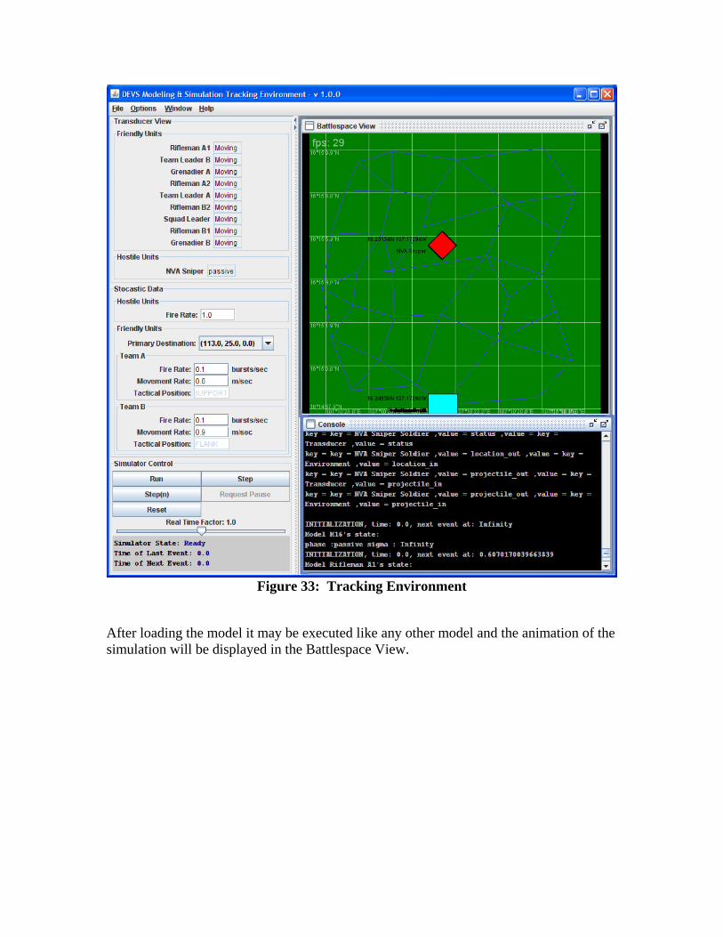
Figure 33: Tracking Environment
After loading the model it may be executed like any other model and the animation of the simulation will be displayed in the Battlespace View.