Angle Bar Check
21
School of Civil Engineering Sydney NSW 2006 AUSTRALIA http://www.civil.usyd.edu.au/ Centre for Advanced Structural Engineering Behaviour of Single Angle Steel Beams Research Report No R884 N S Trahair BSc BE MEngSc PhD DEng August 2007
Transcript of Angle Bar Check
School of Civil Engineering Sydney NSW 2006 AUSTRALIA http://www.civil.usyd.edu.au/ Centre for Advanced Structural Engineering
Behaviour of Single Angle Steel Beams Research Report No R884 N S Trahair BSc BE MEngSc PhD DEng August 2007
School of Civil Engineering Centre for Advanced Structural Engineering
http://www.civil.usyd.edu.au/
Behaviour of Single Angle Steel Beams
Research Report No R884
N S Trahair BSc BE MEngSc PhD DEng August 2007
Abstract: A single angle steel beam is commonly loaded eccentrically in a plane inclined to the principal planes (Fig. 1), so that the beam undergoes primary bending and shear about both principal axes, torsion, and bearing at the supports. The strengths of such beams are affected by local buckling effects on their section resistances, and by lateral buckling effects and torsion on the interaction between the major and minor axis moments during biaxial bending. This paper summarises the behaviour of single angle steel beams investigated in a series of recent papers. For these papers, the general case of unrestrained biaxial bending and torsion was simplified successively (Fig, 2) into restrained biaxial bending, lateral buckling, unrestrained biaxial bending, buckling and torsion, and biaxial bending and torsion The paper concludes that despite the apparent simplicity of single angle beams, their behaviour is often complex and their strengths difficult to predict. The papers summarised provide a design method which is rational, consistent and economical. Keywords: angles, beams, bending, buckling, design, elasticity, member resistance, moments, section capacity, steel, torsion.

Behaviour of Single Angle Steel Beams August 2007
School of Civil Engineering Research Report No R884
2
Copyright Notice Behaviour of Single Angle Steel Beams © 2007 N.S.Trahair [email protected] This publication may be redistributed freely in its entirety and in its original form without the consent of the copyright owner. Use of material contained in this publication in any other published works must be appropriately referenced, and, if necessary, permission sought from the author. Published by: School of Civil Engineering The University of Sydney Sydney NSW 2006 AUSTRALIA August 2007 http://www.civil.usyd.edu.au

Behaviour of Single Angle Steel Beams August 2007
School of Civil Engineering Research Report No R884
3
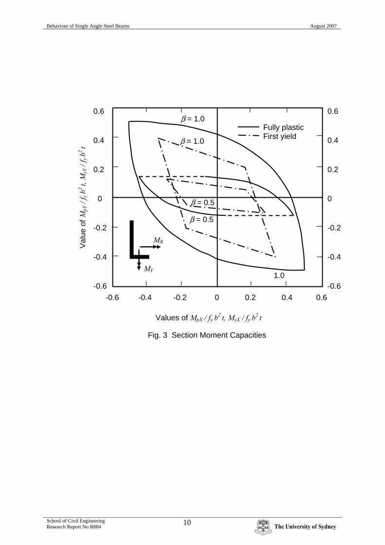
INTRODUCTION Although the geometry and loading of single angle section steel beams are usually comparatively simple as shown in Fig. 1, their behaviour may be extremely complicated, and the accurate prediction of their strengths very difficult. A single angle section beam is commonly loaded eccentrically in a plane inclined to the principal planes (Fig. 1), so that the beam undergoes primary bending and shear about both principal axes, torsion, and bearing at the supports. Even in the very unusual cases when only one of these actions occurs, the primary fully plastic or first yield resistances may be reduced by local or lateral buckling effects, or increased by stiffening effects which become important at large rotations. When all of these actions occur, as they usually do, there are first- and second-order interactions between them, some of which are very difficult to predict. This paper summarises the behaviour of single angle steel beams investigated in a series of recent papers (Trahair, 2002a, b, 2003, 2004, 2005a, b, 2007). For these papers, the general case of unrestrained biaxial bending and torsion (Fig. 1) was simplified successively into restrained biaxial bending (Fig. 2a), lateral buckling (Fig. 2b), unrestrained biaxial bending (Fig. 2c), and buckling and torsion (Fig. 2d). SECTION RESISTANCES First Yield Moment Resistance The combinations of first yield rectangular axis moments (Trahair, 2002a) acting on two angle sections are shown in Fig. 3. Fully Plastic Moment Resistance The combinations of fully plastic rectangular axis moments (Trahair, 2002a) acting on an equal angle are also shown in Fig. 3. It can be seen that these are significantly higher than the first yield moments. It is of interest that fully plastic stress distributions are not possible for some moment combinations, as indicated by the dashed lines in Fig. 3. They correspond to angles with fully plastic shorter legs and less than fully plastic longer legs. Local Buckling Moment Resistance The section moment resistances of single angle beams depend on their local buckling moment resistances. Beams with high local buckling resistances may be classified as being plastic or compact. The section moment resistances of such beams are equal to their fully plastic moments. Beams with lower local buckling resistances may be classified as semi-compact, in which case their section moment resistances may be interpolated between their fully plastic and first yield moments. Beams with even lower local buckling resistances may be classified as slender, and their section moment resistances reduced below their first yield moments.

Behaviour of Single Angle Steel Beams August 2007
School of Civil Engineering Research Report No R884
4
The local buckling moment resistance of a single angle is higher than that of the compression flange of an I-section beam of similar proportions, because bending of the angle causes non-uniform compression and even tension in the legs (Fig. 4). Thus design recommendations based on the local buckling of I-section beam flanges will be unnecessarily conservative when applied to angles in bending. The elastic local buckling of single angle beams has been studied (Fig. 5) using the computer program THIN-WALL (Papangelis and Hancock, 1997) and used to develop improved local buckling classifications (Trahair, 2002a). Shear, Torsion, and Bearing Resistances The shear resistance of a slender leg of an angle beam is reduced by local buckling effects which are difficult to assess because one longitudinal edge of the leg is unsupported (Fig. 4), and so recommendations based on the local buckling of I-section webs supported along both longitudinal edges must be modified. Reduced recommendations are given in Trahair (2002b). Similar reductions have been suggested for the bearing resistance of the leg of a single angle beam in Trahair (2002b). The torsion resistances of single angle beams are unaffected by local buckling because the stress distribution in uniform torsion is balanced across the thickness of the angle, and so may be based on the fully plastic uniform torque (Trahair et al, 2001). Recommendations for the combined shear and torsion resistances are given in Trahair (2002b). RESTRAINED BIAXIAL BENDING Trahair (2002a) considered the first-order (small deformation) elastic analysis of the biaxial bending (without torsion) of single angle beams with elastic restraints which prevent deflection out of the plane of loading and lateral buckling. Such beams can be designed using the proposals for the section moment, shear, bearing and torsion resistances developed in Trahair (2002a, b). MEMBER ANALYSIS METHODOLOGY The uniform biaxial bending and torsion of unrestrained simply supported steel angle beams has been analysed (Trahair, 2003, 2004, 2005a, b, 2007) using an approximate elastic non-linear analysis of the small twist rotations of beams with initial twists to predict the maximum principal plane bending moments. This simplistic method is an extension of a first yield method of strength prediction which takes approximate account of the additional strength beyond first yield of compact beams which can reach full plasticity. It makes small rotation approximations which generally overestimate the principal plane moments. The method apparently ignores the effects of residual stresses and initial crookedness which cause early yielding and reduce strength. These are compensated for by using initial twists which are increased sufficiently so that the small rotation analysis will predict the lateral buckling design strengths proposed in Trahair (2003).

Behaviour of Single Angle Steel Beams August 2007
School of Civil Engineering Research Report No R884
5
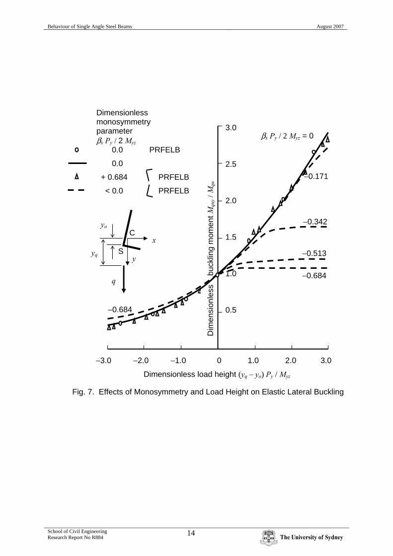
This method also ignores the reductions shown in Fig. 6 in the torque resultants of eccentrically applied loads which occur at finite rotations (Trahair 2005a). It is conservative to ignore these reductions. The maximum moments predicted by this method were used to develop simple methods of designing unrestrained steel angle beams against biaxial bending and torsion. Compact beams (Trahair, 2002a) were considered to have failed when these maximum moments reach the fully plastic moment combinations, and beams which are just semi-compact (Trahair, 2002a) when these moments reach the first yield combinations. The resistances of angle beams to bearing, shear, and uniform torsion may be checked separately by comparing the appropriate design actions (which may be determined by a simple first-order analysis of the beam) with the corresponding design resistances recommended in Trahair (2002b). LATERAL BUCKLING The elastic lateral buckling of a beam is influenced by the moment distribution, the effect of load height, and the section properties, including the effects of monosymmetry about the axis of bending (Trahair, 1993), and may be predicted by using the computer program PRFELB (Papangelis et al, 1997). Loads acting above the shear centre reduce the elastic buckling moments, while monosymmetry effects cause unequal angle beams to have lower elastic buckling moments when the short leg is in tension than when it is in compression (Fig. 7). Trahair (2003) considered the lateral buckling strengths of unrestrained steel single angle beams which are loaded in the major principal plane as shown in Fig. 2b, so that there are no primary minor axis bending or torsion effects. For this, an approximate method of predicting the elastic second-order twist rotations of an equal angle beam in uniform bending was developed, whose accuracy was investigated subsequently in a study (Trahair, 2005c) of the elastic non-linear large rotation behaviour of beams under non-uniform torsion. The approximate predicted rotations were used with the earlier formulations (Trahair, 2002a) of the biaxial bending moment resistances to investigate the lateral buckling strengths of angle section beams with initial twist rotations which approximated the effects of geometrical imperfections (initial crookedness and twist) and residual stresses. The investigation included simple design proposals which approximated the predicted lateral buckling strengths, which are shown in Fig. 8. It is of interest to note that at high slendernesses, the proposed strengths Mb are equal to the minor axis moment resistances Msy which are higher than the elastic buckling moments Mquy. Clearly, the worst that can happen to such a beam under lateral buckling influences is that it will twist through 90o so the applied moments act about the minor axis. Under these circumstances, lateral buckling should be regarded as a serviceability condition and tested against under the serviceability loads, rather than as a strength condition.

Behaviour of Single Angle Steel Beams August 2007
School of Civil Engineering Research Report No R884
6
UNRESTRAINED BIAXIAL BENDING Another paper (Trahair, 2004) considered the biaxial bending of unrestrained steel angle section beams which are loaded through the shear centre as shown in Fig. 2c, so that there are no primary torsion actions. The applied minor axis moments add to those induced by lateral buckling effects and interact with the major axis moments to reduce the beam resistance, as shown in Figs 9 (for equal angles) and 10 (for unequal angles. Fig. 10 indicates that the biaxial bending strengths of unequal angles depend on the senses of the applied moments. BUCKLING AND TORSION Following papers (Trahair, 2005a, b) extended the earlier study (Trahair, 2003) on the lateral buckling strengths of single angle section beams (Fig. 2b). In this extension, the beam was considered to be loaded in a plane parallel to the major principal plane but eccentric from the shear centre as shown in Fig. 2d, so that there were primary major axis bending and torsion actions, but no primary minor axis bending actions. Torsion increases the twist rotations and induces additional minor axis bending moments, thereby reducing the beam moment resistance, as shown in Fig. 11. UNRESTRAINED BIAXIAL BENDING AND TORSION The last paper completed (Trahair, 2007) extended the paper (Trahair, 2005a) on the lateral buckling and torsion of single equal angle section beams (Fig. 2d). In this extension, the beam was considered to be loaded in a plane inclined to the major principal plane and eccentric from the shear centre as shown in Fig. 1, so that there are primary biaxial bending and torsion actions. The effects of torsion on the biaxial bending strengths of equal angle beams are shown in Fig. 12. It can be seen that these depend on the sense of the applied torques which may increase or decrease the strength. The reason for this is illustrated in Fig. 13, where it can be seen that the twist rotation of the angle section caused by the applied torque causes the angle’s stiffer plane to rotate towards that of the applied load when the flange is down, thereby increasing the resistance, or to rotate away when the flange is up, thereby decreasing the resistance.

Behaviour of Single Angle Steel Beams August 2007
School of Civil Engineering Research Report No R884
7
CONCLUSIONS This paper summarises the behaviour of single angle steel beams investigated in a series of recent papers (Trahair, 2002a, b, 2003, 2004, 2005a, b, 2007). For these papers, the general case of unrestrained biaxial bending and torsion (Fig. 1) has been simplified successively into restrained biaxial bending (Fig. 2a), lateral buckling (Fig. 2b), unrestrained biaxial bending (Fig. 2c), and buckling and torsion (Fig. 2d). A single angle section beam is commonly loaded eccentrically in a plane inclined to the principal planes (Fig. 1), so that the beam undergoes primary bending and shear about both principal axes, torsion, and bearing at the supports. The strengths of the beams are affected by local buckling effects on their section resistances, and by lateral buckling effects and torsion on the interaction between the major and minor axis moments during biaxial bending. Local buckling effects in angle beams are not well predicted by using the strengths of I-beam flange outstands, while the lateral buckling of angle beams is affected by the load height and by monosymmetry if the angle has unequal legs. Torsion reduces the lateral buckling strengths of single angle beams, but may increase the biaxial bending strengths if the torque causes the beam’s stiffer principal plane to rotate towards that of the applied load. It can be concluded that despite the apparent simplicity of single angle beams, the behaviour is often complex and their strengths difficult to predict. The papers summarised provide a design method which is rational, consistent and economical.

Behaviour of Single Angle Steel Beams August 2007
School of Civil Engineering Research Report No R884
8
REFERENCES Papangelis, JP and Hancock, GJ (1997), THIN-WALL – Cross-section Analysis and Finite Strip Buckling Analysis of Thin-Walled Structures, Centre for Advanced Structural Engineering, University of Sydney. Papangelis, JP, Trahair, NS, and Hancock, GJ (1997), PRFELB – Finite Element Flexural-Torsional Buckling Analysis of Plane Frames, Centre for Advanced Structural Engineering, University of Sydney. Trahair, NS (1993), Flexural-Torsional Buckling of Structures, E & FN Spon, London. Trahair, NS (2002a), ‘Moment Capacities of Steel Angle Sections’, Journal of Structural Engineering, ASCE, 128 (11), 1387 - 93. Trahair, NS (2002b), ‘Bearing, Shear, and Torsion Capacities of Steel Angle Sections’, Journal of Structural Engineering, ASCE, 128 (11), 1394 - 8. Trahair, NS (2003), ‘Lateral Buckling Strengths of Steel Angle Section Beams’, Journal of Structural Engineering, ASCE, 129 (6), 784 - 91. Trahair, NS (2004), ‘Biaxial Bending of Steel Angle Section Beams’, Journal of Structural Engineering, ASCE, 130 (4), 554 - 61. Trahair, NS (2005a), ‘Buckling and Torsion of Steel Equal Angle Section Beams’, Journal of Structural Engineering, ASCE, 131 (4), 467 – 73. Trahair, NS (2005b), ‘Buckling and Torsion of Steel Unequal Angle Section Beams’, Journal of Structural Engineering, ASCE, 131 (4), 473 – 80. Trahair, NS (2005c), ‘Non-Linear Elastic Non-Uniform Torsion’, Journal of Structural Engineering, ASCE, 131 (7), 1135 − 1142. Trahair, NS (2007), ‘Biaxial Bending and Torsion of Steel Equal Angle Section Beams’, Journal of Structural Engineering, ASCE, 133 (1), 78 − 84. Trahair, NS, Bradford, MA, and Nethercot, DA (2001), The Behaviour and Design of Steel Structures to BS5950, 3rd British edition, E & FN Spon, London. Trahair, NS, and Teh, LH (2001), ‘Second Order Moments In Torsion Members’, Engineering Structures, 23, 631-642.

Behaviour of Single Angle Steel Beams August 2007
School of Civil Engineering Research Report No R884
9
(b) Lateral buckling
x
S y
q
Fig. 2. Single Angle Beam Behaviour
(c) Unrestrained biaxial bending
q
x
S y
(a) Restrained biaxial bending
q
x
S y
(d) Buckling and torsion
y
q
e
x
S
z
L Y
q
(a) Elevation (b) Cross-section (c) Loading
Fig. 1. Eccentrically Loaded Angle Section Beam
Flange up
q
e
q
e
Flange down
S
t
x
α X C
Y y
b
t
β b
Behaviour of Single Angle Steel Beams August 2007
School of Civil Engineering Research Report No R884
10
MX
β = 1.0
1.0
0.6 0.4 0.2 0 -0.2 -0.4 -0.6
0.6 0.4 0.2 0 -0.2 -0.4 -0.6
-0.6 -0.4 -0.2 0 0.2 0.4 0.6
Values of MpX / fy b2 t, MyX / fy b2 t
Val
ue o
f MpY
/ f y
b2 t,
MyY
/ f y
b2 t
Fig. 3 Section Moment Capacities
MY
β = 1.0
β = 0.5
β = 0.5
Fully plastic First yield

Behaviour of Single Angle Steel Beams August 2007
School of Civil Engineering Research Report No R884
11
Fig. 4 Stress Distributions
I-section
Angle
Bending Shear
C
T
C
T

Behaviour of Single Angle Steel Beams August 2007
School of Civil Engineering Research Report No R884
12
C
C
C
T C
C
T T
C
T
C C kext
kexc
keyt
keyc
kpxt
kpyt
kpxc kpyc
kc
Val
ues
of k
eyt,
k pyt
40
35
30
25
20
15
10
5
0
8
7
6
5
4
3
2
1
0 0.5 0.6 0.7 0.8 0.9 1.0
T
T
C
Val
ues
of k
c, k e
xt, k
exc,
k eyc
, kpx
t, k p
xc, k
pyc
Leg length ratio β
Fig. 5. Elastic Local Buckling Coefficients

Behaviour of Single Angle Steel Beams August 2007
School of Civil Engineering Research Report No R884
13
(a) Movement of point of application (b) Change of point of application
q
e sec α
e sec α cos (α + θ) α = 45o
S
θ
e
θ
S
q
Fig. 6. Reduction of Load Eccentricity
Behaviour of Single Angle Steel Beams August 2007
School of Civil Engineering Research Report No R884
14
Dimensionless monosymmetry parameter βx Py / 2 Myz 0.0 PRFELB
0.0
+ 0.684 PRFELB
< 0.0 PRFELB
yq
yo
S
C
y
q
x
−3.0 −2.0 −1.0 0 1.0 2.0 3.0
Dimensionless load height (yq – yo) Py / Myz
Dim
ensi
onle
ss
buc
klin
g m
omen
t Mqu
y / M
qu
Fig. 7. Effects of Monosymmetry and Load Height on Elastic Lateral Buckling
βx Py / 2 Myz = 0
−0.171
−0.342
−0.513
−0.684
−0.684
3.0 2.5 2.0 1.5 1.0 0.5

Behaviour of Single Angle Steel Beams August 2007
School of Civil Engineering Research Report No R884
15
1.0 0.8 0.6 0.4 0.2 0
0 0.5 1.0 1.5 2.0 2.5 3.0 Modified slenderness λe = √(Msx / Mquy)
Fig. 8. Proposed Lateral Buckling Strengths
Pro
pose
d di
men
sion
less
mom
ent s
treng
ths
Mb /
Msx
λx
Msx / Msx
Elastic buckling
Mb / Msx
Mquy / Msx
Msy / Msx
λe λy

Behaviour of Single Angle Steel Beams August 2007
School of Civil Engineering Research Report No R884
16
≥ 1.414
1.124
0.835
0.545
1.0 0.8 0.6 0.4 0.2
λe ≤ 0.257
Approximation Second-order calculations
Mx / M
pxm
0 0.1 0.2 0.3 0.4 0.5
My / Mpym
Mx Mx
My My
Fig. 9. Biaxial Bending Strengths of Compact Equal Angles

Behaviour of Single Angle Steel Beams August 2007
School of Civil Engineering Research Report No R884
17
Fully plastic
First yield
λ < 0.26 λ > 2.08
0.5 0.4 0.3 0.2 0.1
Mpy / fy b2t, Myy / fy b2t
− 0.2 − 0.1 0 0.1 0.2
Mpx
/ f y
b2 t,
M
yx /
f y b2 t
β = 0.5
Fig. 10. Biaxial Bending Strengths of an Unequal Angle

Behaviour of Single Angle Steel Beams August 2007
School of Civil Engineering Research Report No R884
18
Lateral buckling strength Mb / Mpxm
M = Mpym
0.15
0.30
0.45
0.60
0.75
Dim
ensi
onle
ss m
omen
t res
ista
nce
M /
Mpx
m
Modified slenderness λe = √(Mpxm / Myz)
0 0.2 0.4 0.6 0.8 1.0 1.2 1.4 1.6
1.0 0.8 0.6 0.4 0.2 0
θ1 = 0 rad. M = Mpxm
Second-order calculations Approximation
αm = 1.0
Elastic buckling Myz / Mpxm
Fig. 11. Buckling and Torsion Strengths of Compact Equal Angles

Behaviour of Single Angle Steel Beams August 2007
School of Civil Engineering Research Report No R884
19
λe = 1.4 θ1 = 0
1.0 0.8 0.6 0.4 0.2 0
λe = 1.4 θ1 = 0.7
0 0.1 0.2 0.3 0.4 0.5
Fig. 12 Biaxial Bending and Torsion of Compact Equal Angles
(My)p /Mpxm
(Mx) p
/Mpx
m
Accurate solutions Approximations
λe = 0.3, θ1 = −0.7
λe = 0.3, θ1 = 0
λe = 0.3, θ1 = 0.7

Behaviour of Single Angle Steel Beams August 2007
School of Civil Engineering Research Report No R884
20
Fig. 13 Flange Up or Down ?
q
x
y α
φ
α − φ q
x
y α
φ
α + φ
(a) Flange down (b) Flange up