
Angle and ramus fracture, simple
59
Angle and ramus fracture, simple wire fixation
-
Upload
giupitas -
Category
Health & Medicine
-
view
124 -
download
1
Transcript of Angle and ramus fracture, simple

Angle and ramus fracture, simple wire fixation

Intraosseous wire fixation of angle fractures is a nonrigidtechnique that requires 5-6 weeks of postoperative MMF. It isindicated when plate/screw fixation is not available and themandibular ramus is likely to rotate upwards and forwardsbecause of the attached muscles. In such instances, closedreduction may not be effective. The intraosseous wire will helpto prevent rotation of the mandibular ramus.

The intraosseous wire must be placed to resist the upward and forward direction inwhich the ramus will tend to rotate. Therefore, it is prudent to place the hole throughthe proximal fragment superiorly to the hole in the distal fragment. It is not necessaryfor the intraosseous wire to engage both buccal and lingual cortices on each side ofthe fracture. It is only necessary to engage the buccal cortices with the wire. Becausethis is a nonrigid technique, 5-6 weeks of MMF must be applied after surgery.
Principles

Arch bars are applied to the teeth and MMF is secured. The patient is monitored for positionalchanges of the mandibular ramus using x-rays. At 6 weeks MMF is released and fracturestability determined by manipulation. The patient is placed on a soft diet and if the occlusionmaintains for a two-week period, the arch bars may be removed.

Exposure of fracture
The fracture should be exposed and any extractions determined necessary be performed.Open reduction in dentate patients usually begins with fixation of the occlusion. However,MMF is not desirable when using intraosseous wire fixation until the wire is to be tightened.It is easier to drill the holes in the bone and to pass the wire while the patient’s jaws areopen.

The “Vestibular” incision or “Ward modified” incision can be used for standard fracturefixation techniques. In order to more easily approach the operative field it is preferred toextend the mesial cutting into the vestibule with a release incision. The region of themandibular angle & ramus can best be exposed by extending the standard vestibular incisionin a superior direction up the ascending ramus. The incision can be altered depending on thearea of the ramus/mandibular angle process that needs exposure and treatment.
Intraoral approach to the mandibular angle & ramus
PrinciplesVestibular incisions
A) Vestibular incision B) “Ward” modified incision
Oral contamination isnot a contraindicationfor an intraoral incision.

Sensory buccal nerve
The sensory buccal nerve crosses the upper anterior rim of the mandibular ascending ramusin the region of the coronoid notch. It is usually below the mucosa running above thetemporalis muscle fibers. When the posterior vestibular incision is carried sharply along thebony rim, the buccal nerve is at risk of transsection resulting in numbness in the buccalmucosal region. Therefore, to protect the nerve, the posterior incision is to be extendedbluntly as soon as the lower coronoid notch is reached.

Sensory buccal nerve

Sensory buccal nerveMental nerve
The mental nerve is a branch of the fifthcranial nerve (trigeminal nerve). This nerveprovides sensation to the anterior mandibularvestibule, lip and chin. When the incisionisextended posterior to the canine teeth, themental nerve can be damaged. Keep theincision superior to the mental nerve in thebody region. Particularly in the extendedintraoral approach, care must be taken toprotect the mental nerve in the anterior bodyregion.

Mental nerve

photography of anatomical preparationshowing the sensory buccal nerve.
photography of anatomical preparationshowing


The bony attachments of the buccinator muscle run a course below themucogingival junction opposite to the molars and along the oblique lineascending as the anterolateral rim of the ascending ramus. The attachmentsextend back into the pterygomandibular raphe. The buccinator is innervated bythe buccal branch of the facial nerve. The muscle belongs to the mimetic musclesystem and has a unique functional structure allowing for movement comparableto peristaltic motion. Its detachment can result in an impaired bolus transport.Reminder: The buccinator muscle belongs to the mimic muscle system and has aunique functional structure allowing for a movement comparable to a peristalticmotion. The deep fibers run in parallel bundles from the modiolus to thepterygomandibular raphe at the level of the occlusal plane (intercalar region) andaccount for the buccinator mechanism building up a ridge towards the occlusalplane. Its detachment can result in an impaired bolus transport out of the buccalspace which can be annoying for the patient. The buccinator is innervated by themotor buccal branch of the facial nerve.

The lateral mucogingival vestibular incision transects the lower attachment of the buccinatormuscle. Stripping the mucoperiosteal flap laterally dislocates the lower border of the muscle.To reattach the muscle, the sutures for wound closure in the lateral vestibular should not onlybe superficial. The suture should catch all layers (mucosa and muscle) as a safeguard formuscle reattachment.
The buccinator is innervated by the motor buccal branch of the facial nerve.

The buccinator muscle belongs to the mimic muscle system and has a unique functional structureallowing for a movement comparable to a peristaltic motion. The deep fibers run in parallel bundlesfrom the modiolus to the pterygomandibular raphe at the level of the occlusal plane (intercalarregion) and account for the buccinator mechanism building up a ridge towards the occlusal plane. Itsdetachment can result in an impaired bolus transport out of the buccal space which is troublesomefor the patient.
Reminder:


Vestibular incision
Unless contraindicated, infiltrate the area with a local anesthetic containing a vasoconstrictor.Make an incision through the mucosa in the vestibule approximately 5 mm away from theattached gingiva (in the mucogingival junction),extending up the external oblique ridge.

Step 1. Injection of Vasoconstrictor
The oral mucosa, submucosa, and facial muscles are lushly vascularized.Submucosal injection of a vasoconstrictor can remarkably reduce the amount ofhemorrhage during incision and dissection.
Step 2. Incsion
In the body and posterior portion of the mandible, the incision is placed 3 to 5 mminferior to the mucogingival junction (see Fig. 8.10). Leaving unattached mucosa onthe alveolus facilitates closure. The posterior extent of the incision is made over theexternal oblique ridge, traversing mucosa, submucosa, buccinator muscle,buccopharyngeal fascia, and periosteum (Fig. 8.5A).

Photograph showing incision location when vestibular approach is used to expose theramus and posterior body of the mandible. Note that there is some unattached mucosaremaining along the attached gingiva to facilitate closure.
The incision is usually no more superior than the occlusalplane of the mandibular teeth to help prevent herniationof the buccal fat pad into the surgical field, a nuisanceduring surgery. The buccal portion of the buccal fat pad isusually not more inferior than the level of the occlusalplane The incision is usually no more superior than theocclusal plane of the mandibular teeth to help preventherniation of the buccal fat pad into the surgical field, anuisance during surgery. The buccal portion of the buccalfat pad is usually not more inferior than the level of theocclusal plane (Fig. 8.4).
Placement of the incision at this level also may spare thebuccal artery and nerve, although their damage is more anuisance than a clinical problem. If the buccal artery issevered, bleeding is easily controlled by coagulation.

The buccal fat pad consists of a main body and four extensions: buccal,
pterygoid, pterygomandibular, and temporal. The body is centrally positioned. Thebuccal extension lies superficially within the cheek, while the pterygoid,pterygomandibular, and temporal extensions are more deeply situated. The buccalextension is the most superficial segment of the fat pad and imparts fullness to thecheek. It enters the cheek below the parotid duct and extends along the anteriorborder of the masseter as it descends into the mandibular retromolar region. Itoverlies the main portion of the buccinator muscle as it crosses the cheek. In thecheek, the fat pad is anterior to the ramus. Its caudal extension intraorally is on aplane tangential with the occlusal surface of the mandibular third molar (see Fig.8.4). Its anterior limit is marked by the facial vessels, which are in the same plane asthe buccal fat pad. The parotid duct lies superficial to the fat pad and thenpenetrates the fat pad and buccinator to enter the oral cavity opposite the secondmolar. The buccal extension of the fat pad is limited by the masseteric fascia. A deepextension of the masseteric fascia blends with the fascia along the lateral surface ofthe buccinator. This fascial layer lines the deep surface of the buccal fat that is incontact with the buccinator.

The buccal fat pad first described by Marie Bichat in 1801 islocated in an extended three-dimensional compartment with itsmain mass or cheek portion overlying the posterolateral aspect ofthe buccinator muscle and the maxillary tuberosity, which is partlycovered by the anterior border of the masseter muscle. The majorprocesses of the fat pad stretch into deep temporal,pterygomaxillary and pterygoid region. The fat is distinct fromfacial fat and similar to orbital fat in consistency and its globule-likestructure, to which it connects through the infraorbital fissure. Thefacial vessels run along the anterior border of the cheek portion.The fascial layers (capsule) enveloping the buccal fat pad on themedial surface next to the buccinator muscle are rarely ruptured ina subperiosteal dissection along the mandibular body and angle.However, when going up the ramus subsequent to a verticaldivision of the buccinator muscle anterior to thepterygomandibular raphe in order to reach beyond the coronoidnotch the inner capsule of the fat pad can be breached leading to aherniation that will obstruct the vision in the surgical field.

Step 3. Subperiosteal Dissection of the MandibleSubperiosteal dissection of the mandibular body is relatively simple compared to that of the symphysis because there are fewer Sharpey fibers inserting into the bone.
Dissection can then proceedposteriorly along the lateral surfaceof the mandibular body/ramus. Thesurgeon should stay within theperiosteal envelope to preventlacerating the facial vessels, whichare just superficial to theperiosteum (Fig. 8.2).
Figure 8.2 Anatomic dissection of the mandibular body showingrelation of facial vessels to bone. The only tissue between them isthe periosteum.

Facial VesselsThe facial artery and vein are usually not encountered during the mandibular vestibular approachunless dissection through the periosteum occurs in the region of the mandibular antegonial notch.
The facial artery arises from the externalcarotid artery in the carotid triangle of theneck. At or close to its origin, it is crossed bythe posterior belly of the digastric muscle,the stylohyoid muscles, and the hypoglossalnerve. In the submandibular triangle, thefacial artery ascends deep to thesubmandibular gland, grooving its deep andsuperior aspect, and then passessuperficially to reach the inferior border ofthe mandible. As the artery crosses themandible at the anterior border of themasseter muscle, it is covered on itssuperficial surface by skin and platysmamuscle, and its pulsations can be felt at thislocation.

Vessels
The facial vessels cross the inferior border of the mandible at the levelcorresponding to the anterior border of the masseter muscle. The vessels areembedded in the lower extensions of the buccal fat pad.

Vessels
Facial artery and vein

Facial artery and vein
The artery is always locatedanterior to the vein. Aperiosteal layer separatesthe vascular bundle fromthe lateral bony surface ofthe mandible.
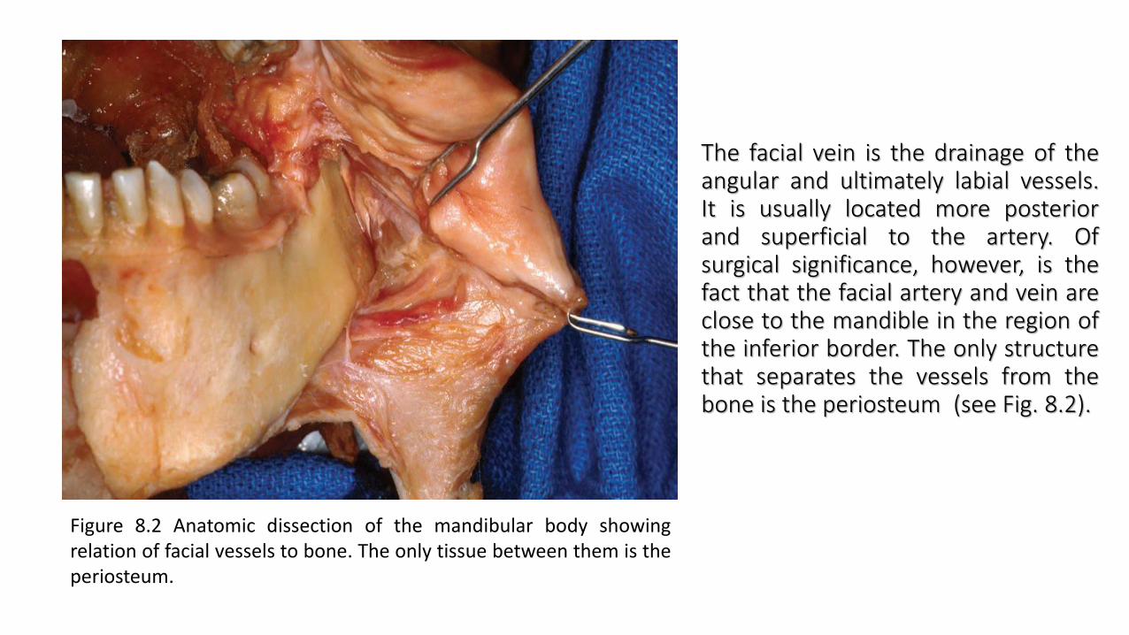
The facial vein is the drainage of theangular and ultimately labial vessels.It is usually located more posteriorand superficial to the artery. Ofsurgical significance, however, is thefact that the facial artery and vein areclose to the mandible in the region ofthe inferior border. The only structurethat separates the vessels from thebone is the periosteum (see Fig. 8.2).
Figure 8.2 Anatomic dissection of the mandibular body showingrelation of facial vessels to bone. The only tissue between them is theperiosteum.

Subperiosteal dissection of the ramus.
Posteriorly, the incision leaves the crest at thesecond molar region and extends laterally toavoid the lingual nerve, which may be directlyover the third molar area. Placing the incisionover the ascending ramus helps to avoid thelingual nerve.Dissection can then proceed posteriorly alongthe lateral surface of the mandibularbody/ramus. The surgeon should stay withinthe periosteal envelope to prevent laceratingthe facial vessels, which are just superficial tothe periosteum (Fig. 8.2).
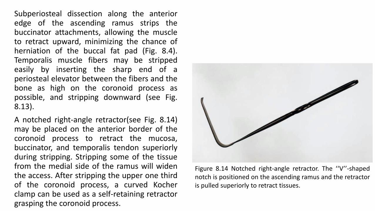
Subperiosteal dissection along the anterioredge of the ascending ramus strips thebuccinator attachments, allowing the muscleto retract upward, minimizing the chance ofherniation of the buccal fat pad (Fig. 8.4).Temporalis muscle fibers may be strippedeasily by inserting the sharp end of aperiosteal elevator between the fibers and thebone as high on the coronoid process aspossible, and stripping downward (see Fig.8.13).
A notched right-angle retractor(see Fig. 8.14)may be placed on the anterior border of thecoronoid process to retract the mucosa,buccinator, and temporalis tendon superiorlyduring stripping. Stripping some of the tissuefrom the medial side of the ramus will widenthe access. After stripping the upper one thirdof the coronoid process, a curved Kocherclamp can be used as a self-retaining retractorgrasping the coronoid process.
Figure 8.14 Notched right-angle retractor. The ‘‘V’’-shapednotch is positioned on the ascending ramus and the retractoris pulled superiorly to retract tissues.

While the buccal tissues areretracted laterally with a right-angle retractor, the massetermuscle is stripped from the lateralsurface of the ramus (Fig. 8.13).Sweeping the periosteal elevatorsuperoinferiorly strips the musclecleanly from the bone. Althoughdirect visualization may be poor,the posterior and inferior bordersof the mandible are readilystripped of pterygomassetericfibers using periosteal elevators, J-strippers, or both. Dissection cancontinue superiorly, exposing thecondylar neck and the entiresigmoid notch. To maintain

exposure of the ramus, Bauer retractors(see Fig. 8.15) inserted into the sigmoidnotch and/or under the inferior border areuseful (see Fig. 8.16). The LaVasseur-Merrillretractor is another useful device thatslides behind and clutches the posteriorborder of the mandible to hold themasseter in a lateral position.
Figure 8.15 Bauer retractors. The flanges at right angle tothe shaft are used to engage the sigmoid notch and/orinferior border of the mandible, allowing retraction of themasseter muscle.
Figure 8.16 Exposure after insertion of Bauer retractors.Note the flange of one retractor is in the sigmoid notchand the flange of the other is under the inferior border ofthe mandible.

This clinical image shows the fracture exposed, reduced, and MMF secured.
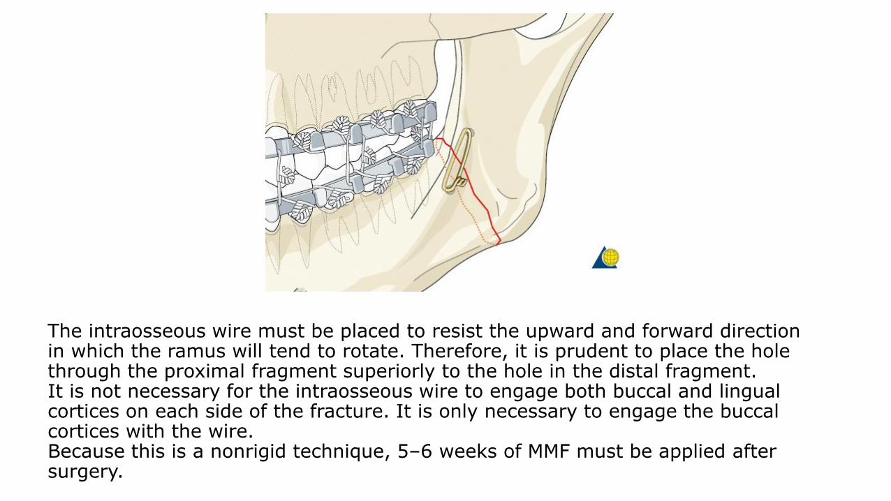
The intraosseous wire must be placed to resist the upward and forward direction in which the ramus will tend to rotate. Therefore, it is prudent to place the hole through the proximal fragment superiorly to the hole in the distal fragment.It is not necessary for the intraosseous wire to engage both buccal and lingual cortices on each side of the fracture. It is only necessary to engage the buccal cortices with the wire.Because this is a nonrigid technique, 5–6 weeks of MMF must be applied after surgery.

A 1.5 mm hole is drilled through the buccal cortex of the distal fragment. A second hole,located more superiorly, is drilled through the buccal cortex of the proximal fragment.If the terminal molar is extracted as part of the procedure, the holes enter the socket. If notooth is extracted, the holes enter the medullary space and exit into the fracture.The holes can be drilled with a drill inserted through the oral cavity or alternatively, aSteinmann pin can be inserted transcutaneously to drill the holes.

Applying internal wire fixation
A 0.5 mm wire (24 gauge) is passed through the holes and preliminarily twistedtogether. Prior to final tightening of the wire, the patient must be placed into occlusionand secured with MMF. The intraosseous wire is then tightened, cut, and twisted down tothe bone.

Case example
Panoramic and PA x-rays show left simple angle fracture associated with ...

… an impacted third molar.

Because it is anticipated that the second molar might be removed in addition to the third molar the soft-tissue incision is made as demonstrated.

Subperiosteal dissection exposes the fracture and the impacted third molar.

The impacted third molar is being removed because it interfered with fracture reduction.

The second molar is also removed because there is a large bony defect along the posterior root.

After making two holes, the wire is then passed from the extraction site out the hole in the proximal fragment.

The wire is then preliminarily tightened. Prior to final tightening, the patient should be placed into MMF.

The wire has been tightened, cut, and bent down to lay against the bone.

To facilitate closure over the second molar extraction site, the flap is undermined with scissors.

Note that the flap has now been mobilized.

The flap has been closed over the extraction site.

MMF is secured and left in position for 5–6 weeks. Note this patient’s preexisting malocclusion.

Postoperative panoramic and PA x-rays show reduction of the fracture, ...

.. the position of the intraosseous wire, and MMF.

Closure of the intraoral incision
After thoroughly irrigating the wound and checking for hemostasis the incision is closed using interrupted or running resorbable sutures.
Wound closure

Step 4. Closure
Closure is adequate in one layer, except in the anterior region. Closure is begun in theposterior areas with resorbable suture. The pass of the needle should grab mucosa,submucosa, the cut edge of the facial muscles, and the periosteum, if possible, The mucosais then closed with a running resorbable suture.
A suspension dressing, such as elastic tape, is useful for several days after the mandibularbuccal vestibular approach has been performed, to prevent hematoma and to maintain theposition of the repositioned facial muscles (Fig. 8.18F).

Surgical dressing
An elastic pressure dressing covering the ramus/condylar process region helps support the soft tissues and prevent prevent hematoma formation.
Intraoral approach to condyle
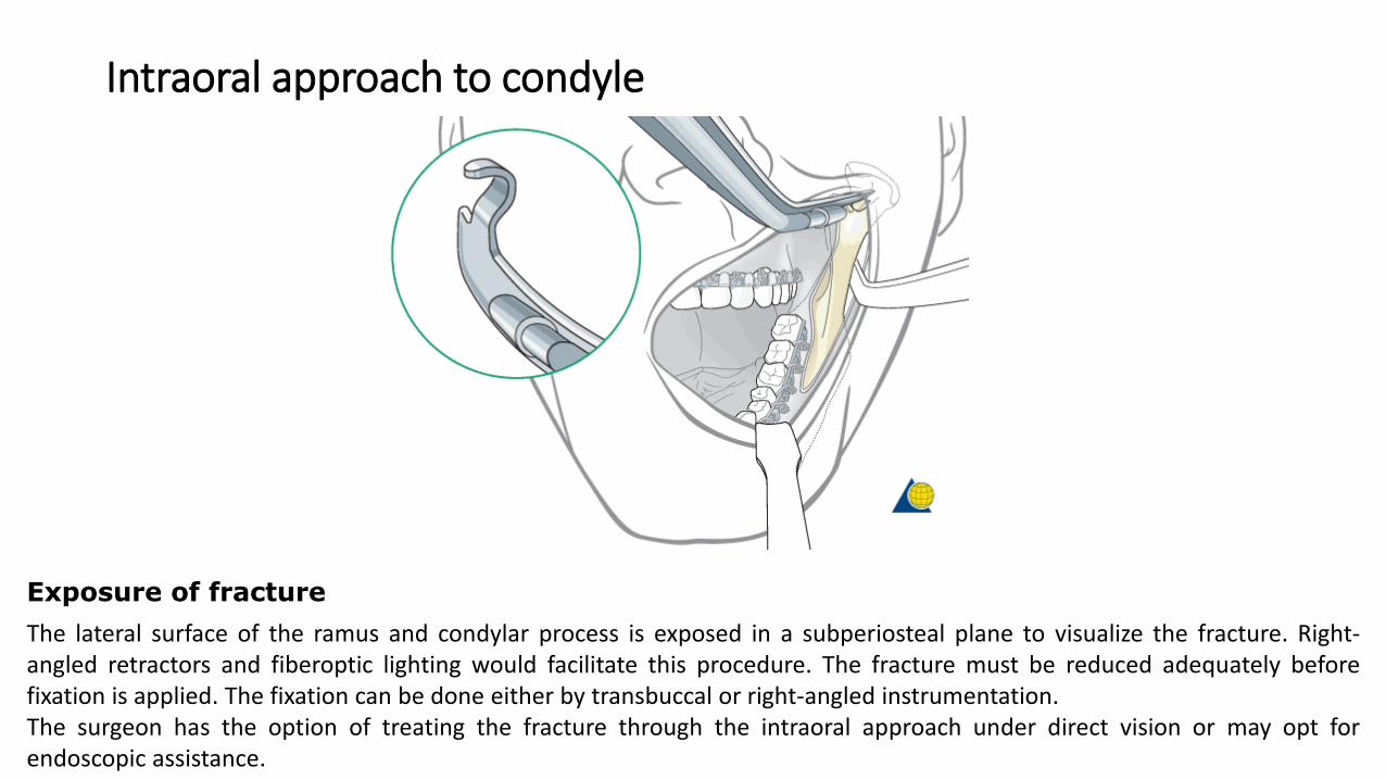
The lateral surface of the ramus and condylar process is exposed in a subperiosteal plane to visualize the fracture. Right-angled retractors and fiberoptic lighting would facilitate this procedure. The fracture must be reduced adequately beforefixation is applied. The fixation can be done either by transbuccal or right-angled instrumentation.The surgeon has the option of treating the fracture through the intraoral approach under direct vision or may opt forendoscopic assistance.
Exposure of fracture

Intraoral approach to condyle
The image shows a clinical example of the transbuccal trocar instrumentation to reduce and fix a fracture of the condylar process.

Safe zones
The safe zones for pin placement are located circumferentially around the whole continuity of themandible along the lower and posterior borders and the condylar processes. There is one zone inthe subcondylar neck that is crossed by the facial nerve trunk in an anterior-posterior directionwhich represents a high-risk zone for nerve injury. Therefore, this area should be avoided.
The condylar process itself can be used for K-wires outside the joint capsule. The posterior borderof the ramus and the bone in the lower border of the outer angle region have the thinnest crosssection of the whole safe zone but the intrabony nerve structures are running in a curvaturelocated superiorly and medially.
Safe zones

The mandibular canal containing the inferior alveolar nerve limits the vertical height of the safe zonecranially in the mandibular body and angle. The vicinity of the mental foramen should be avoided dueto variances in the course of the mandibular canal next to the bony opening.In the symphyseal area although there is a tiny continuation of the mandibular canal (incisal canal)the whole bone stock beneath the tooth apices is available for pin placement.

Bony cross sections and intraosseous structures•Tooth roots•Mandibular canal/inferior alveolar nerve/no man’s land


