AngelCG17 projection matrices - Computer Science | … Computer Graphics I, Fall 2008 4 Pipeline...
22
1 91.427 Computer Graphics I, Fall 2008 Projection Matrices
Transcript of AngelCG17 projection matrices - Computer Science | … Computer Graphics I, Fall 2008 4 Pipeline...
191.427 Computer Graphics I, Fall 2008
Projection Matrices
291.427 Computer Graphics I, Fall 2008
Objectives
•Derive projection matrices used forstandard OpenGL projections
•Introduce oblique projections
•Introduce projection normalization
391.427 Computer Graphics I, Fall 2008
Normalization
•Rather than derive different projectionmatrix for each type of projection
•can convert all projections toorthogonal projections with defaultview volume
•==> can use standard transformationsin pipeline
•==> efficient clipping
491.427 Computer Graphics I, Fall 2008
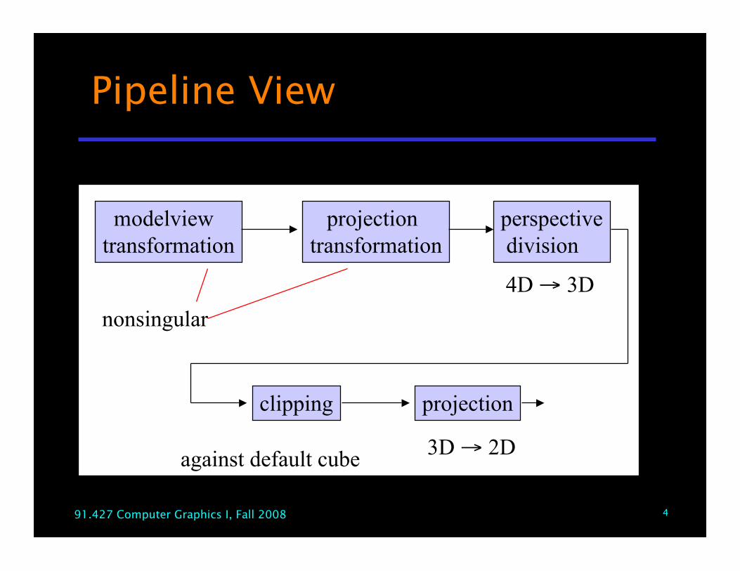
Pipeline View
modelviewtransformation
projectiontransformation
perspective division
clipping projection
nonsingular4D → 3D
against default cube 3D → 2D
591.427 Computer Graphics I, Fall 2008
Notes
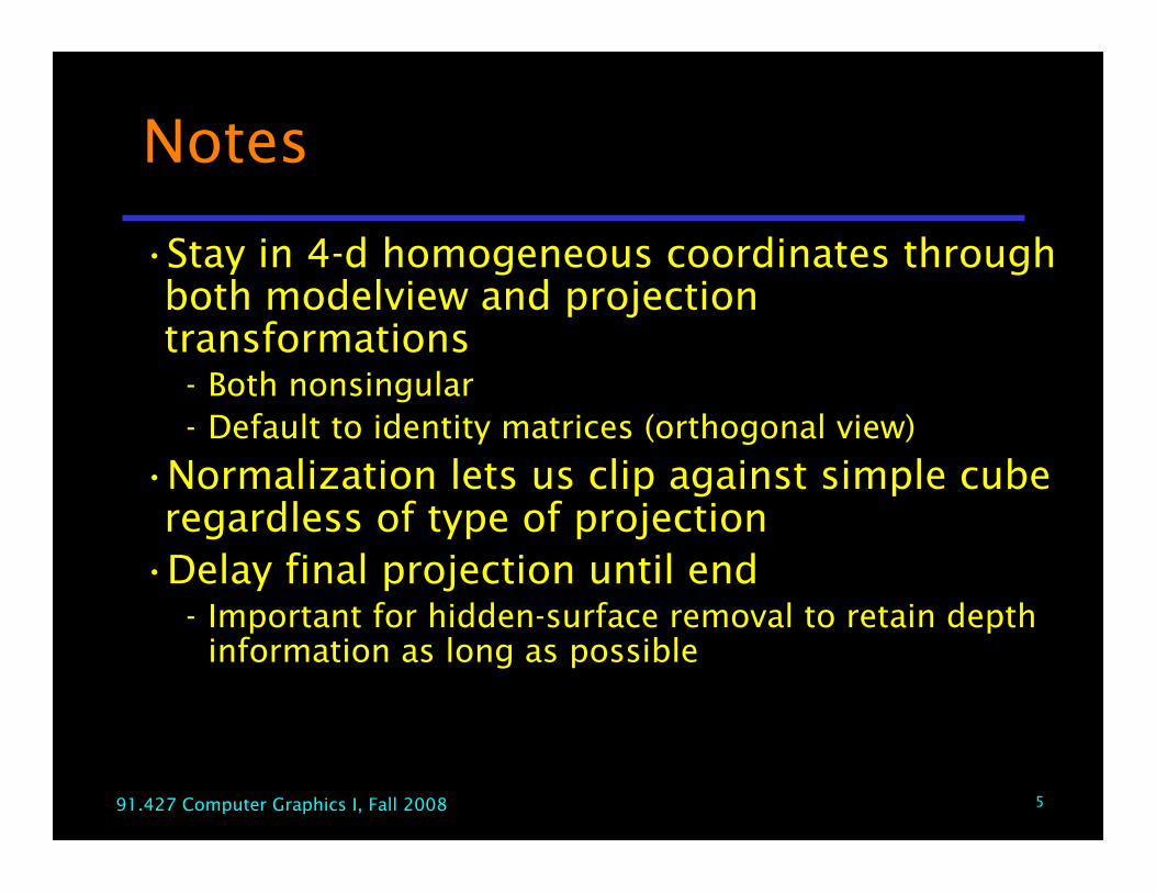
•Stay in 4-d homogeneous coordinates throughboth modelview and projectiontransformations Both nonsingular Default to identity matrices (orthogonal view)
•Normalization lets us clip against simple cuberegardless of type of projection
•Delay final projection until end Important for hidden-surface removal to retain depth
information as long as possible
691.427 Computer Graphics I, Fall 2008
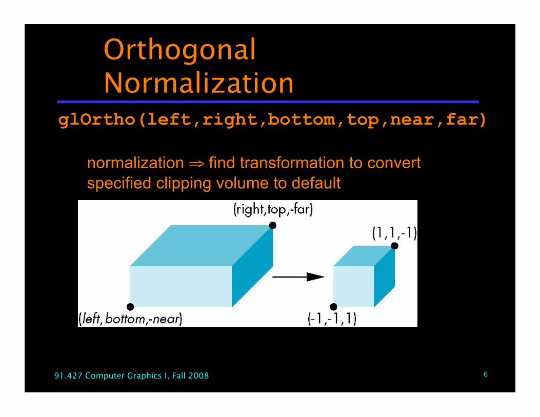
OrthogonalNormalization
glOrtho(left,right,bottom,top,near,far)
normalization ⇒ find transformation to convertspecified clipping volume to default
791.427 Computer Graphics I, Fall 2008
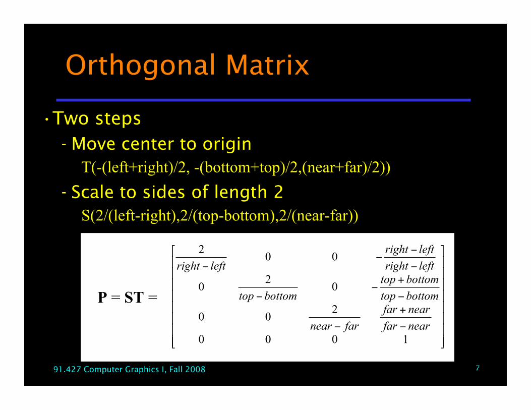
Orthogonal Matrix
•Two steps Move center to origin
T(-(left+right)/2, -(bottom+top)/2,(near+far)/2)) Scale to sides of length 2
S(2/(left-right),2/(top-bottom),2/(near-far))
!!!!!!!!
"
#
$$$$$$$$
%
&
'
+
'
'
+'
'
'
''
'
1000
200
02
0
002
nearfar
nearfar
farnear
bottomtop
bottomtop
bottomtop
leftright
leftright
leftright
P = ST =
891.427 Computer Graphics I, Fall 2008
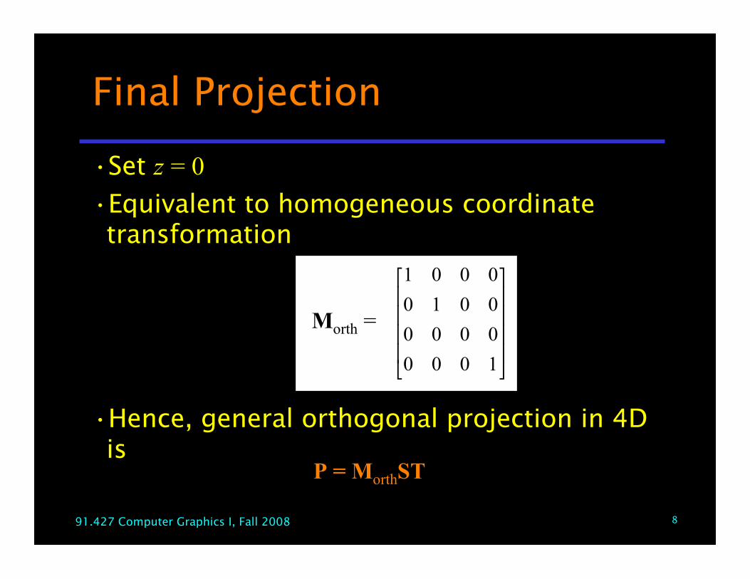
Final Projection
•Set z = 0•Equivalent to homogeneous coordinatetransformation
•Hence, general orthogonal projection in 4Dis
!!!!
"
#
$$$$
%
&
1000
0000
0010
0001
Morth =
P = MorthST
991.427 Computer Graphics I, Fall 2008
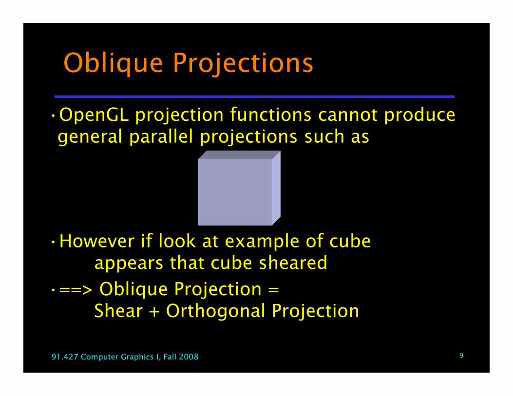
Oblique Projections
•OpenGL projection functions cannot producegeneral parallel projections such as
•However if look at example of cubeappears that cube sheared
•==> Oblique Projection =Shear + Orthogonal Projection

1091.427 Computer Graphics I, Fall 2008
General Shear
top view side view
1191.427 Computer Graphics I, Fall 2008
!!!!
"
#
$$$$
%
&
'
'
1000
0100
0öcot10
0ècot01
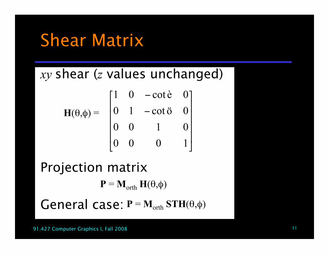
H(θ,φ) =
P = Morth H(θ,φ)
P = Morth STH(θ,φ)
Shear Matrix
xy shear (z values unchanged)
Projection matrix
General case:
1291.427 Computer Graphics I, Fall 2008
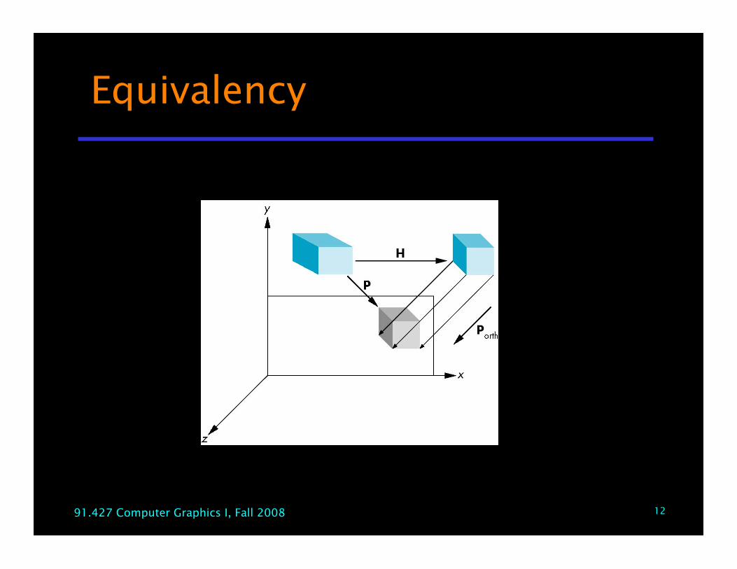
Equivalency
1391.427 Computer Graphics I, Fall 2008
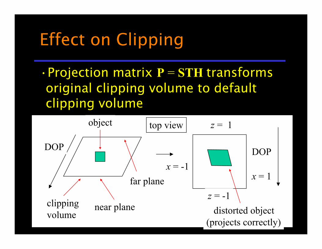
Effect on Clipping
•Projection matrix P = STH transformsoriginal clipping volume to defaultclipping volume
top view
DOP DOP
near plane
far plane
object
clippingvolume
z = -1
z = 1
x = -1x = 1
distorted object(projects correctly)
1491.427 Computer Graphics I, Fall 2008
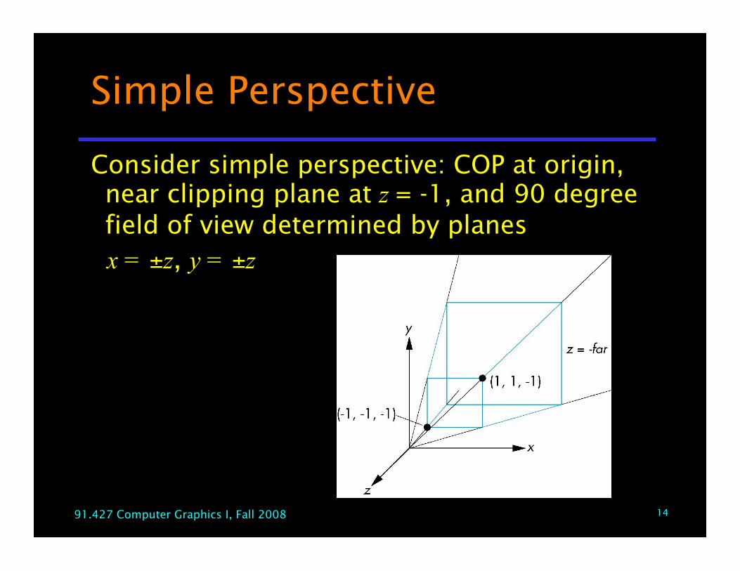
Simple Perspective
Consider simple perspective: COP at origin,near clipping plane at z = -1, and 90 degreefield of view determined by planes
x = ±z, y = ±z
1591.427 Computer Graphics I, Fall 2008
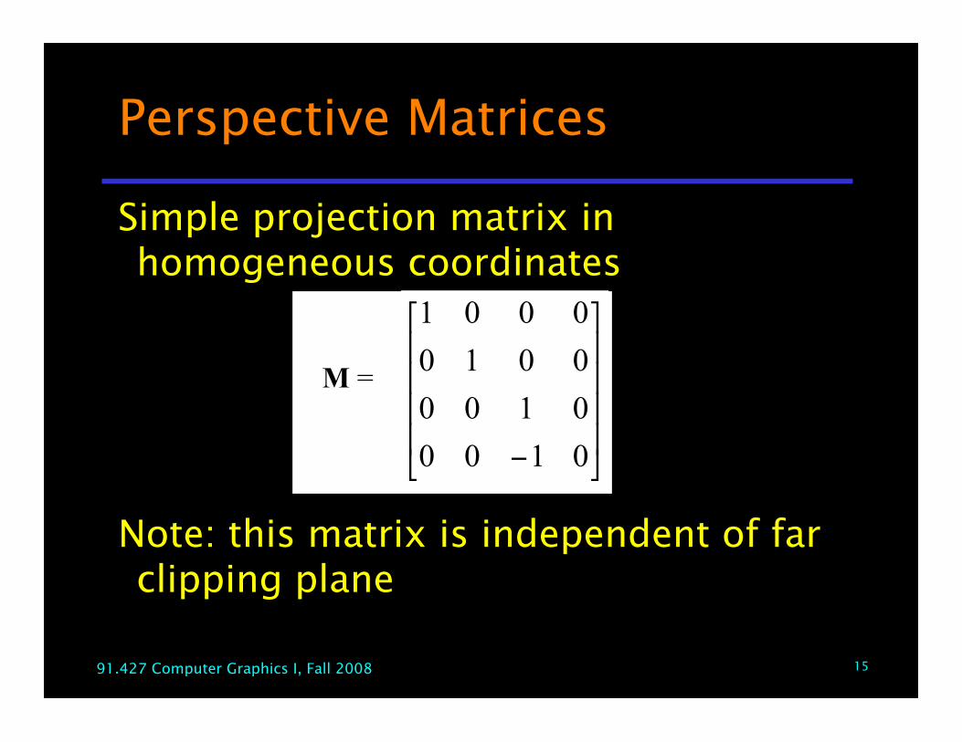
Perspective Matrices
Simple projection matrix inhomogeneous coordinates
Note: this matrix is independent of farclipping plane
!!!!
"
#
$$$$
%
&
' 0100
0100
0010
0001
M =
1691.427 Computer Graphics I, Fall 2008
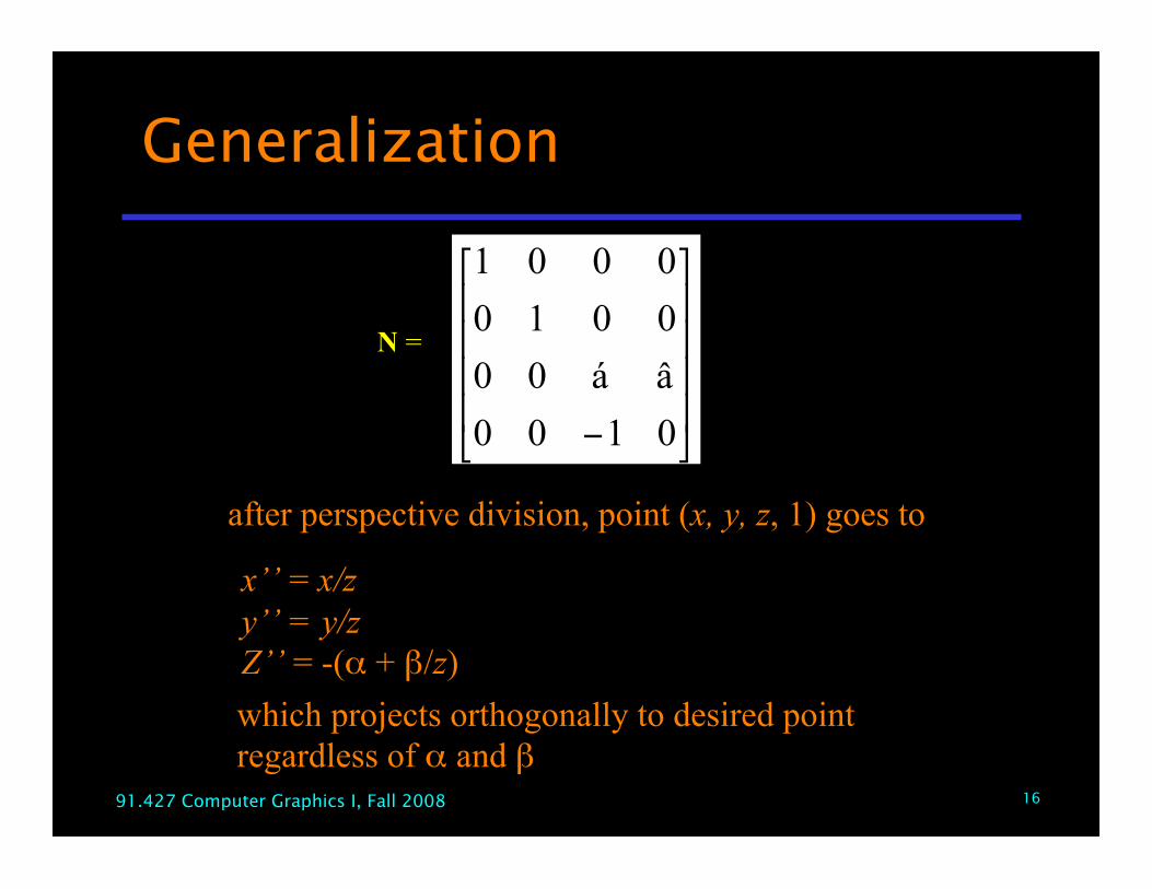
Generalization
!!!!
"
#
$$$$
%
&
' 0100
âá00
0010
0001
after perspective division, point (x, y, z, 1) goes to
x’’ = x/zy’’ = y/zZ’’ = -(α + β/z)which projects orthogonally to desired point regardless of α and β
!!!!
"
#
$$$$
%
&
' 0100
âá00
0010
0001
N =
1791.427 Computer Graphics I, Fall 2008
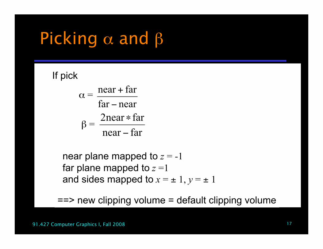
Picking α and β
If pick
α =
β =
nearfar
farnear
!
+
farnear
farnear2
!
"
near plane mapped to z = -1far plane mapped to z =1and sides mapped to x = ± 1, y = ± 1
==> new clipping volume = default clipping volume
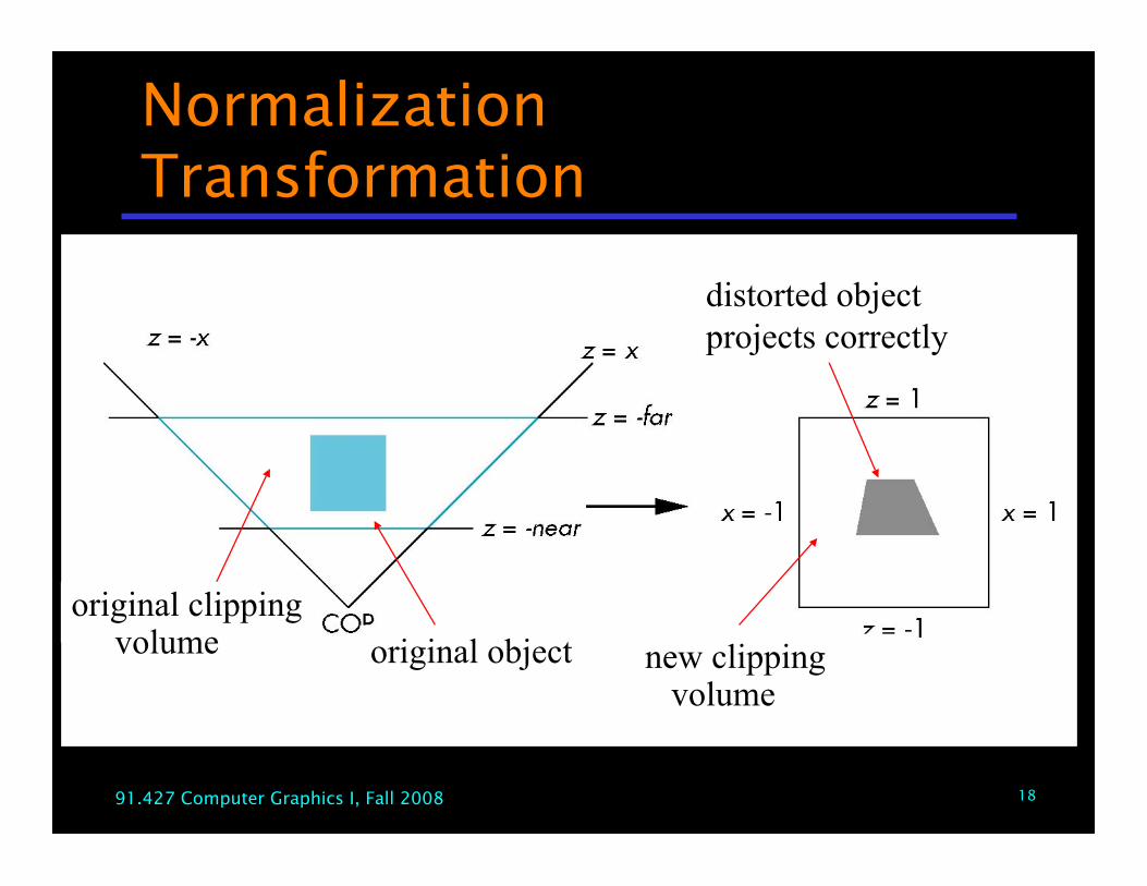
1891.427 Computer Graphics I, Fall 2008
NormalizationTransformation
original clipping volume original object new clipping
volume
distorted objectprojects correctly
1991.427 Computer Graphics I, Fall 2008
Normalization andHidden-Surface Removal
•Selection of form of perspective matrices mayappear somewhat arbitrary
•But chosen so that if z1 > z2 in original clippingvolume ==> for transformed points z1’ > z2’
•==> hidden surface removal works if first applynormalization transformation
•However, formula z’’ = -(α + β/z) ==> distances distortedby normalization
•==> can cause numerical problems•especially if near distance is small
2091.427 Computer Graphics I, Fall 2008
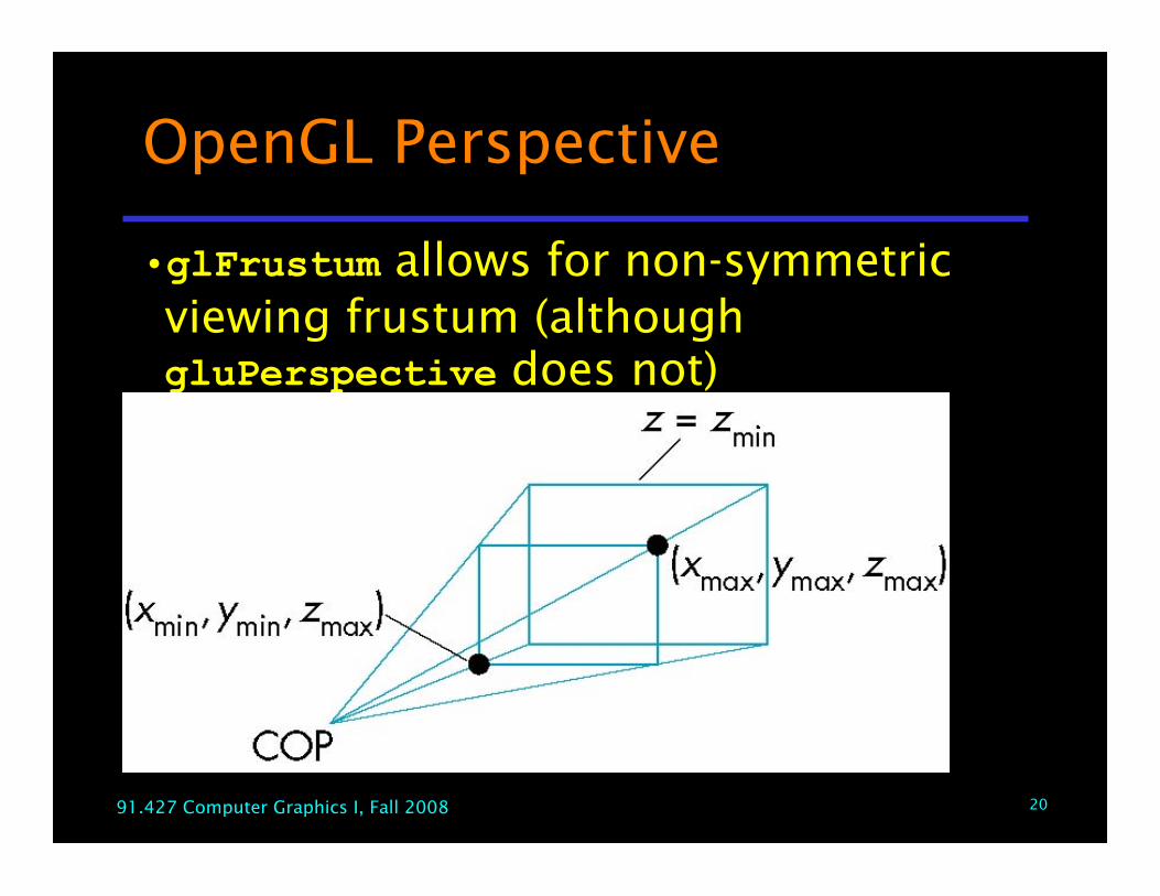
OpenGL Perspective
•glFrustum allows for non-symmetricviewing frustum (althoughgluPerspective does not)
2191.427 Computer Graphics I, Fall 2008
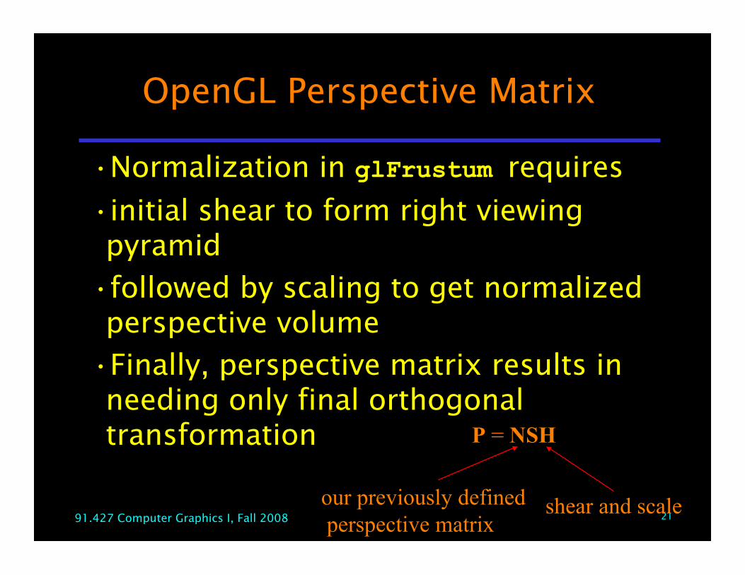
OpenGL Perspective Matrix
•Normalization in glFrustum requires
•initial shear to form right viewingpyramid
•followed by scaling to get normalizedperspective volume
•Finally, perspective matrix results inneeding only final orthogonaltransformation P = NSH
our previously defined perspective matrix
shear and scale
2291.427 Computer Graphics I, Fall 2008
Why do it this way?
•Normalization allows for singlepipeline
•for both perspective and orthogonalviewing
•Stay in 4-d homogeneous coordinatesas long as possible
•to retain 3-d information needed forhidden-surface removal and shading
•Simplify clipping