Android Operated Wireless Robot Using 8051 MCU
24
CERTIFICATE This is to certify that the project report entitled “Android Controlled Wireless Robot Using 8051(AT89S52) Micro controller” being submitted by Kamal Pradhan, Reg. No. 10358/12 of Sambalpur University Institute of Information Technology, Jyoti Vihar, Burla is a work of collection carried out by him under my guidance and supervision for the session 2013-2014. In my opinion the project report has fulfilled the requirement according to the regulation and standard necessary for submission. Mr. Santanu Kumar Dash (Signature & Date with official seal) 1
-
Upload
kamal-pradhan -
Category
Engineering
-
view
9.305 -
download
6
Transcript of Android Operated Wireless Robot Using 8051 MCU
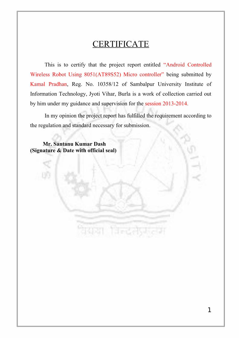
CERTIFICATE
This is to certify that the project report entitled “Android Controlled
Wireless Robot Using 8051(AT89S52) Micro controller” being submitted by
Kamal Pradhan, Reg. No. 10358/12 of Sambalpur University Institute of
Information Technology, Jyoti Vihar, Burla is a work of collection carried out
by him under my guidance and supervision for the session 2013-2014.
In my opinion the project report has fulfilled the requirement according to
the regulation and standard necessary for submission.
Mr. Santanu Kumar Dash (Signature & Date with official seal)
1

ACKNOWLEDGEMENT
I express my deep and sincere thanks to my guide Mr. Santanu Kumar
Dash. He helped me in selecting this project and also guided me throughout the
project. He also helped me by taking a lot of pain and sacrificing his personal
valuable time in completion of this practical project as well as the project report.
My heartfelt thanks to Prof.S.S.Pujari, Director of Sambalpur
University Institute of Information Technology for his encouragement and
overall supervision in bringing out this project report.
Last but not least, I am heartiest thanks to my friends and seniors,
Chandan kumar Sahu , Santanu kumar patel and Ambika Sahu who helped me
a lot during the project work.
Above all I owe to my beloved parents whose bless and supports are
always with me.
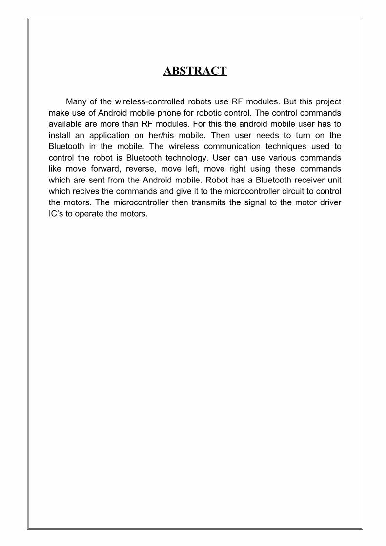
ABSTRACT
Many of the wireless-controlled robots use RF modules. But this project make use of Android mobile phone for robotic control. The control commands available are more than RF modules. For this the android mobile user has to install an application on her/his mobile. Then user needs to turn on the Bluetooth in the mobile. The wireless communication techniques used to control the robot is Bluetooth technology. User can use various commands like move forward, reverse, move left, move right using these commands which are sent from the Android mobile. Robot has a Bluetooth receiver unit which recives the commands and give it to the microcontroller circuit to control the motors. The microcontroller then transmits the signal to the motor driver IC’s to operate the motors.
CONTENTS
INTRODUCTION
TOP LEVEL DESIGN
2.1 Functional block diagram
2.2 System Explanation
2.3 Pictorial diagram
HARDWARE DEVELOPMENT
SOFTWARE DEVELOPMENT
4.1 Flow chart
4.2 Software code
CONCLUSION
6.1 ADVANTAGE
6.2 APPLICATION
6.3 FUTURE SCOPE
6.4 CONCLUSION
REFERENCE
INTRODUCTION
1.1 OVERVIEW OF THE PROJECT
The project aims in designing a Robot that can be operated using Android mobile phone. The controlling of the Robot is done wirelessly through Android smart phone using the Bluetooth feature present in it. Here in the project the Android smart phone is used as a remote control for operating the Robot.
Android is a software stack for mobile devices that includes an operating system, middleware and key applications. Android boasts a healthy array of connectivity options, including Wi-Fi, Bluetooth, and wireless data over a cellular connection (for example, GPRS, EDGE ( Enhanced Data rates for GSM Evolution ), and 3G). Android provides access to a wide range of useful libraries and tools that can be used to build rich applications. In addition, Android includes a full set of tools that have been built from the ground up alongside the platform providing developers with high productivity and deep insight into their applications.
Bluetooth is an open standard specification for a radio frequency (RF)-based, short-range connectivity technology that promises to change the face of computing and wireless communication. It is designed to be an inexpensive, wireless networking system for all classes of portable devices, such as laptops, PDAs (personal digital assistants), and mobile phones. It also will enable wireless connections for desktop computers, making connections between monitors, printers, keyboards, and the CPU cable-free.
The controlling device of the whole system is a Microcontroller. Bluetooth module, DC motors are interfaced to the Microcontroller. The data received by the Bluetooth module from Android smart phone is fed as input to the controller. The controller acts accordingly on the DC motors of the Robot. The robot in the project can be made to move in all the four directions using the Android phone. The direction of the robot is indicated using LED indicators of the Robot system. In achieving the task the controller is loaded with a program written using Embedded ‘C’ language.
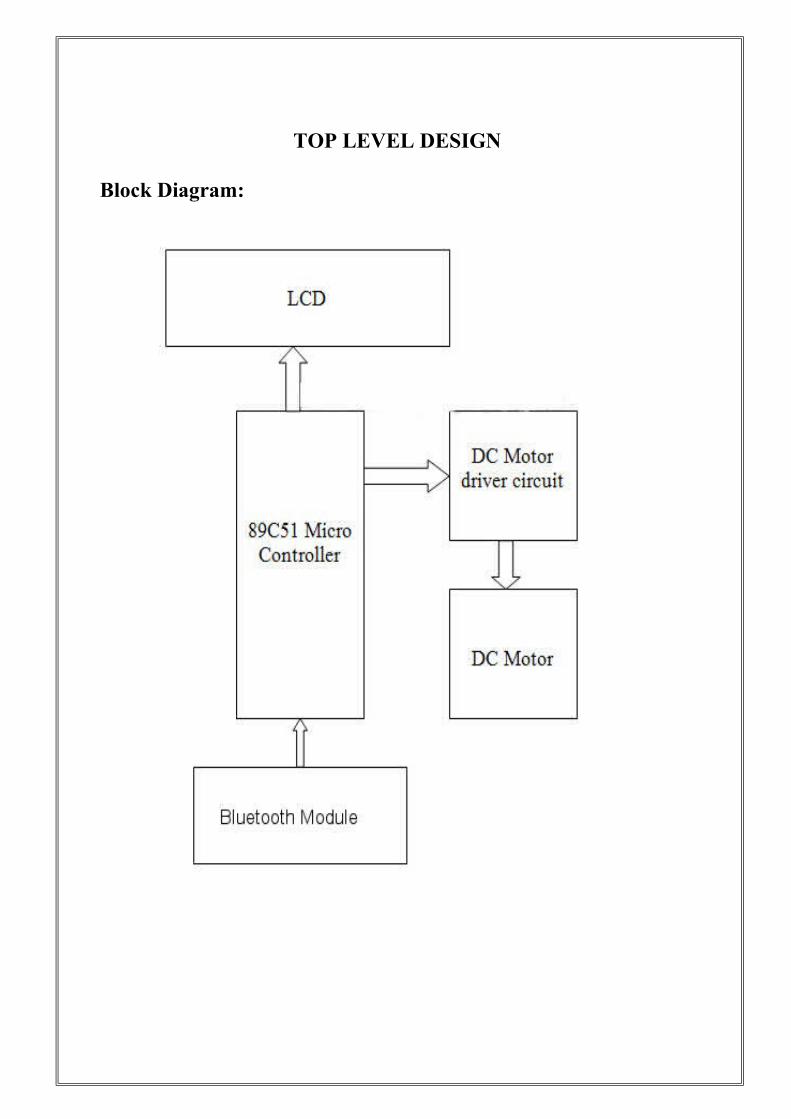
TOP LEVEL DESIGN
Block Diagram:
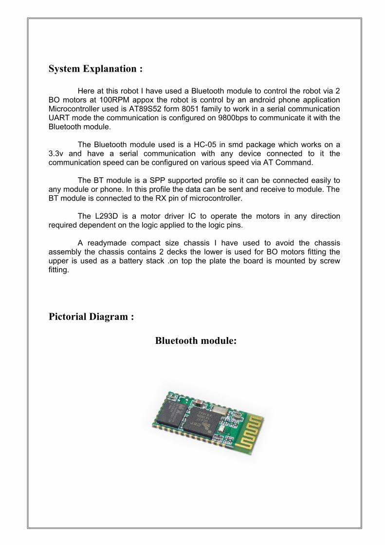
System Explanation :
Here at this robot I have used a Bluetooth module to control the robot via 2 BO motors at 100RPM appox the robot is control by an android phone application Microcontroller used is AT89S52 form 8051 family to work in a serial communication UART mode the communication is configured on 9800bps to communicate it with the Bluetooth module.
The Bluetooth module used is a HC-05 in smd package which works on a
3.3v and have a serial communication with any device connected to it the communication speed can be configured on various speed via AT Command.
The BT module is a SPP supported profile so it can be connected easily to any module or phone. In this profile the data can be sent and receive to module. The BT module is connected to the RX pin of microcontroller.
The L293D is a motor driver IC to operate the motors in any direction required dependent on the logic applied to the logic pins.
A readymade compact size chassis I have used to avoid the chassis assembly the chassis contains 2 decks the lower is used for BO motors fitting the upper is used as a battery stack .on top the plate the board is mounted by screw fitting.
Pictorial Diagram :
Bluetooth module:
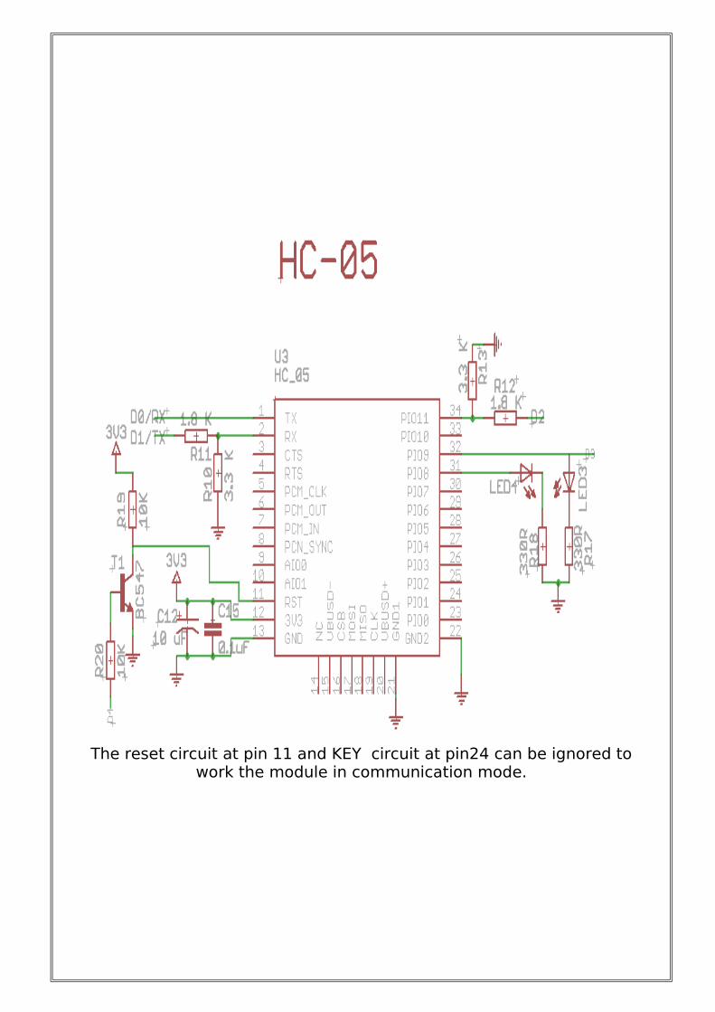
The reset circuit at pin 11 and KEY circuit at pin24 can be ignored to work the module in communication mode.
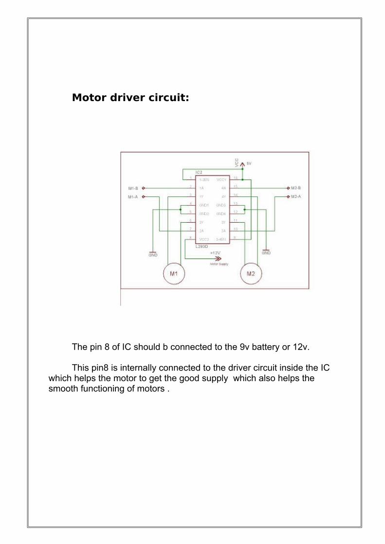
Motor driver circuit:
The pin 8 of IC should b connected to the 9v battery or 12v. This pin8 is internally connected to the driver circuit inside the IC
which helps the motor to get the good supply which also helps the smooth functioning of motors .
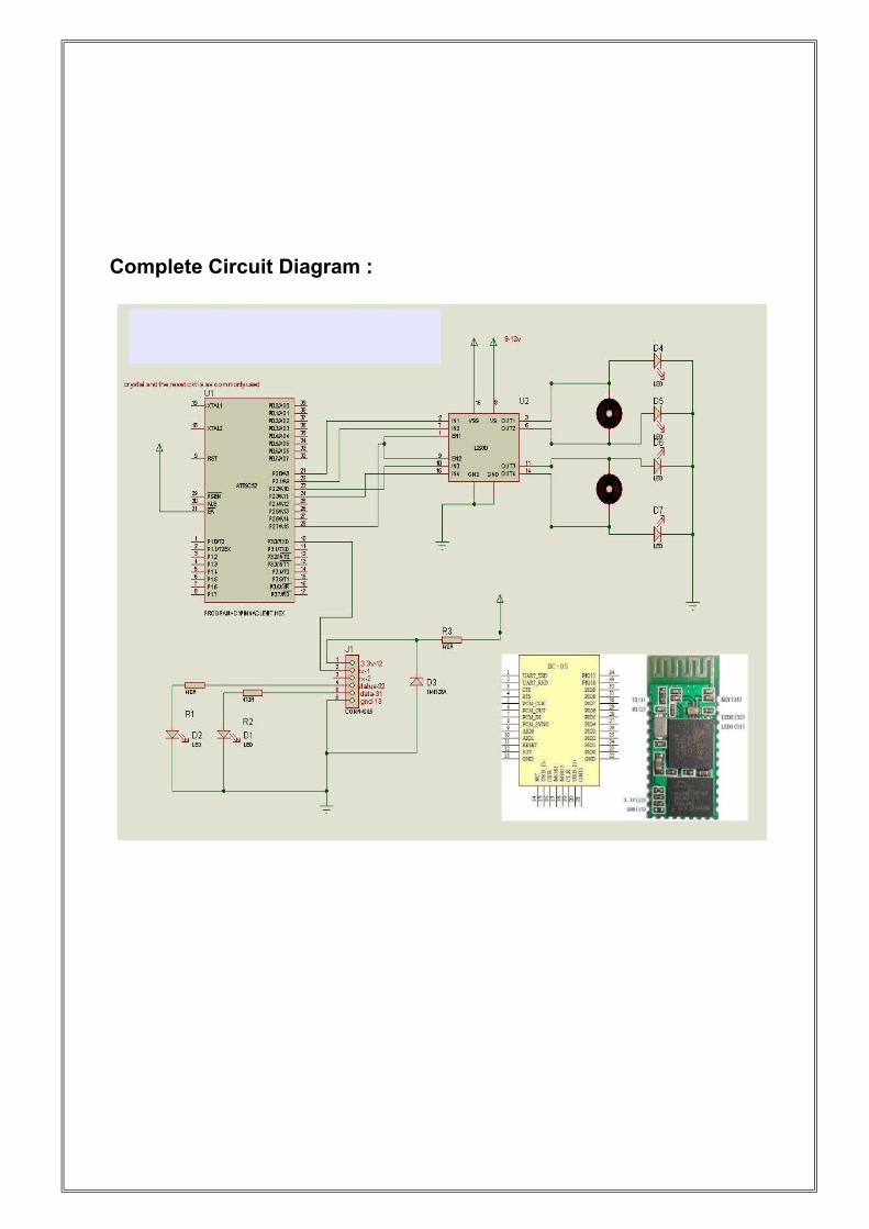
Complete Circuit Diagram :
The Bluetooth module:
The Bluetooth module used is a HC-05 based on SPP supportFeatures:
1) Wireless serial bluetooth port.2) With free power adapter bottom board come with well power regulator.User can connect 3.3 to 5VDC and connect TX and RX to your control IO (general 3.3 to 5V digital input output of MCU or IO is ok, or general TLL IO)3) Easy to connect this module with PC, just search and key
"1234" passcode.4) With white SMD LED on the adapter board, can see the Bluetooth connection status.
Step to connect:
1) Connect the wiring, power up, while the device is not connected, the bluetooth module board has a white LED flashing2) At PC side, search bluetooth device.3) Found name called "HC-05" device4) Connect it, and passcode is "1234"5) While connection is ok, you can see the LED become always on
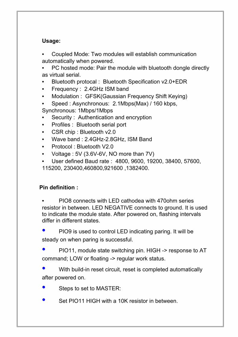
Usage:
• Coupled Mode: Two modules will establish communication automatically when powered. • PC hosted mode: Pair the module with bluetooth dongle directly as virtual serial.• Bluetooth protocal : Bluetooth Specification v2.0+EDR• Frequency : 2.4GHz ISM band• Modulation : GFSK(Gaussian Frequency Shift Keying)• Speed : Asynchronous: 2.1Mbps(Max) / 160 kbps, Synchronous: 1Mbps/1Mbps• Security : Authentication and encryption• Profiles : Bluetooth serial port• CSR chip : Bluetooth v2.0• Wave band : 2.4GHz-2.8GHz, ISM Band• Protocol : Bluetooth V2.0• Voltage : 5V (3.6V-6V, NO more than 7V)• User defined Baud rate : 4800, 9600, 19200, 38400, 57600, 115200, 230400,460800,921600 ,1382400.
Pin definition :
• PIO8 connects with LED cathodea with 470ohm series resistor in between. LED NEGATIVE connects to ground. It is used to indicate the module state. After powered on, flashing intervals differ in different states.
• PIO9 is used to control LED indicating paring. It will be
steady on when paring is successful.
• PIO11, module state switching pin. HIGH -> response to AT
command; LOW or floating -> regular work status.
• With build-in reset circuit, reset is completed automatically
after powered on.
• Steps to set to MASTER:
• Set PIO11 HIGH with a 10K resistor in between.
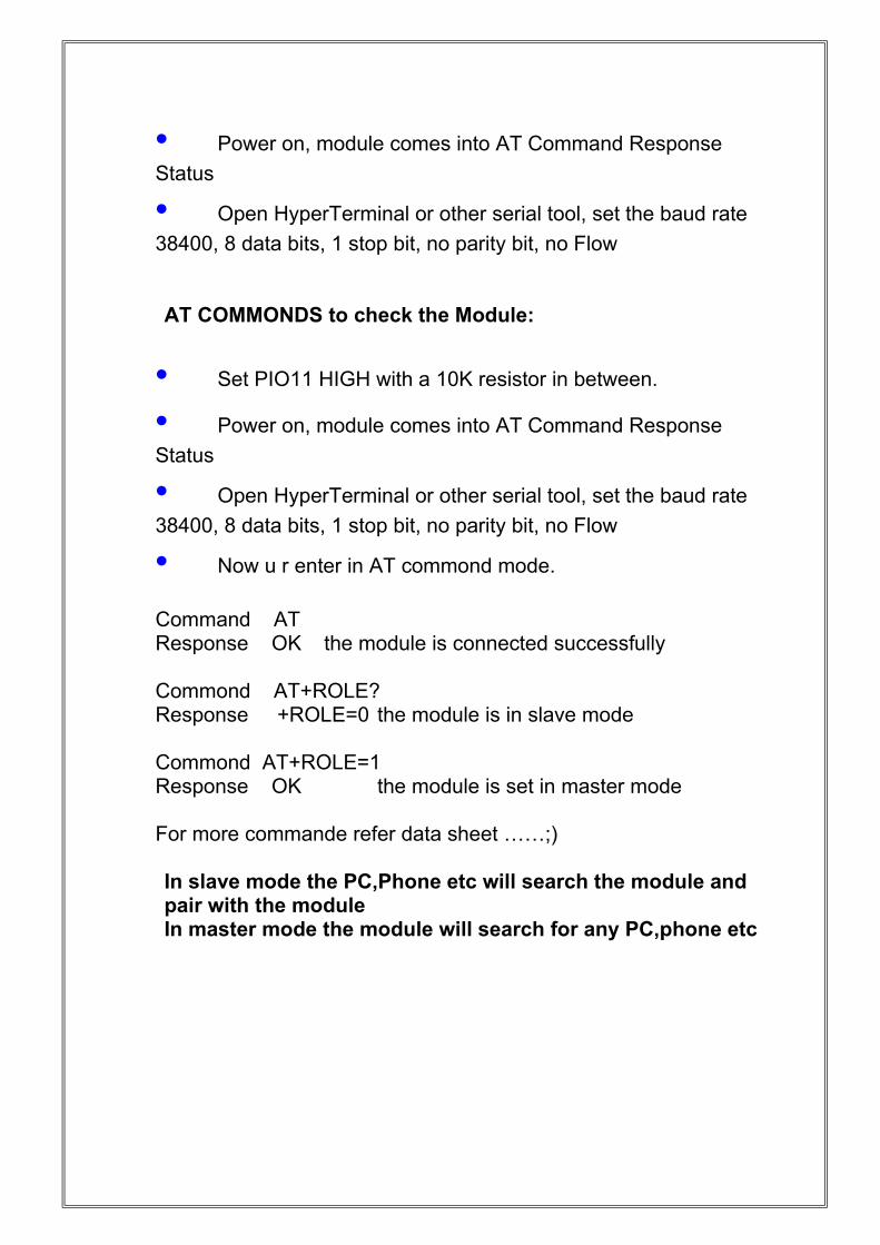
• Power on, module comes into AT Command Response
Status
• Open HyperTerminal or other serial tool, set the baud rate
38400, 8 data bits, 1 stop bit, no parity bit, no Flow
AT COMMONDS to check the Module:
• Set PIO11 HIGH with a 10K resistor in between.
• Power on, module comes into AT Command Response
Status
• Open HyperTerminal or other serial tool, set the baud rate
38400, 8 data bits, 1 stop bit, no parity bit, no Flow
• Now u r enter in AT commond mode.
Command AT Response OK the module is connected successfully
Commond AT+ROLE?Response +ROLE=0 the module is in slave mode
Commond AT+ROLE=1Response OK the module is set in master mode
For more commande refer data sheet ……;)
In slave mode the PC,Phone etc will search the module and pair with the module In master mode the module will search for any PC,phone etc
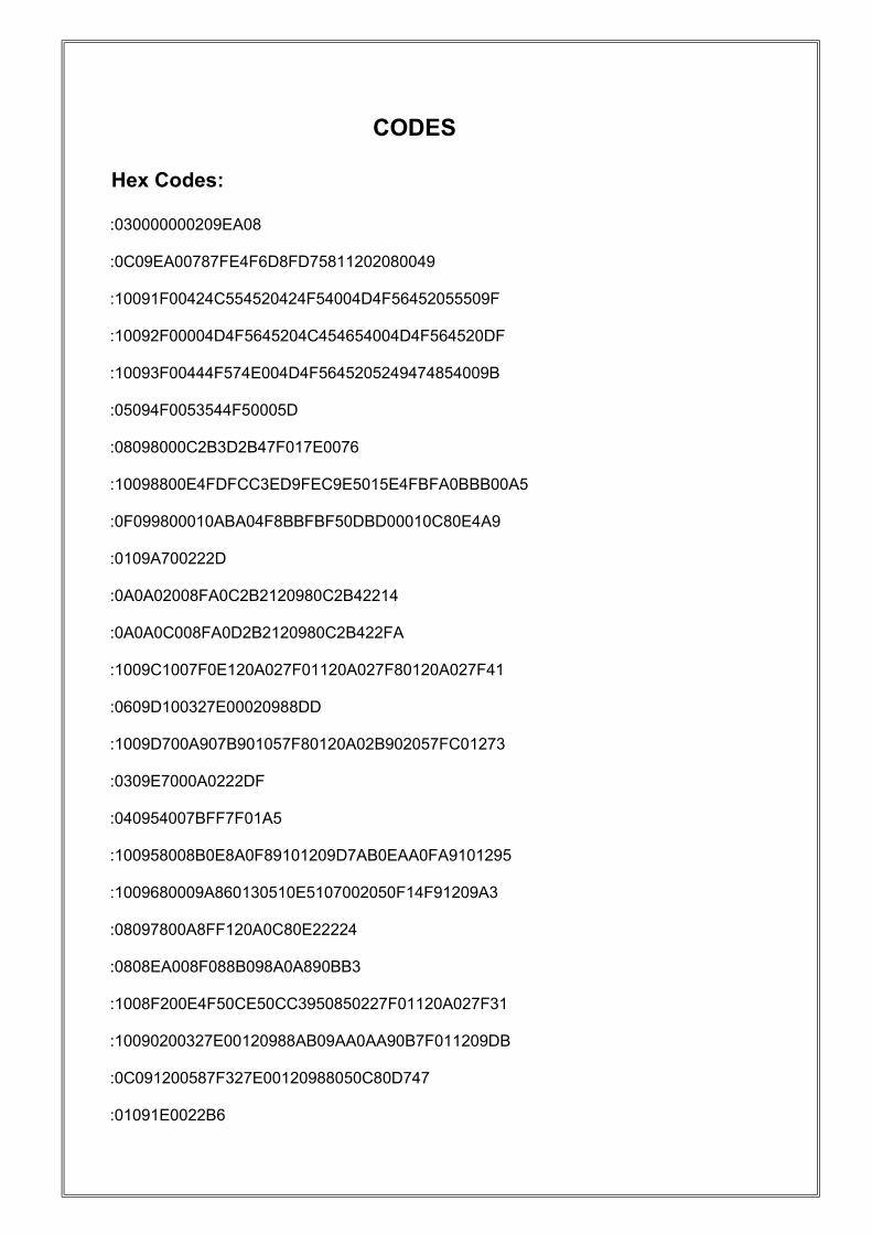
CODES
Hex Codes:
:030000000209EA08
:0C09EA00787FE4F6D8FD75811202080049
:10091F00424C554520424F54004D4F56452055509F
:10092F00004D4F5645204C454654004D4F564520DF
:10093F00444F574E004D4F5645205249474854009B
:05094F0053544F50005D
:08098000C2B3D2B47F017E0076
:10098800E4FDFCC3ED9FEC9E5015E4FBFA0BBB00A5
:0F099800010ABA04F8BBFBF50DBD00010C80E4A9
:0109A700222D
:0A0A02008FA0C2B2120980C2B42214
:0A0A0C008FA0D2B2120980C2B422FA
:1009C1007F0E120A027F01120A027F80120A027F41
:0609D100327E00020988DD
:1009D700A907B901057F80120A02B902057FC01273
:0309E7000A0222DF
:040954007BFF7F01A5
:100958008B0E8A0F89101209D7AB0EAA0FA9101295
:1009680009A860130510E5107002050F14F91209A3
:08097800A8FF120A0C80E22224
:0808EA008F088B098A0A890BB3
:1008F200E4F50CE50CC3950850227F01120A027F31
:10090200327E00120988AB09AA0AA90B7F011209DB
:0C091200587F327E00120988050C80D747
:01091E0022B6
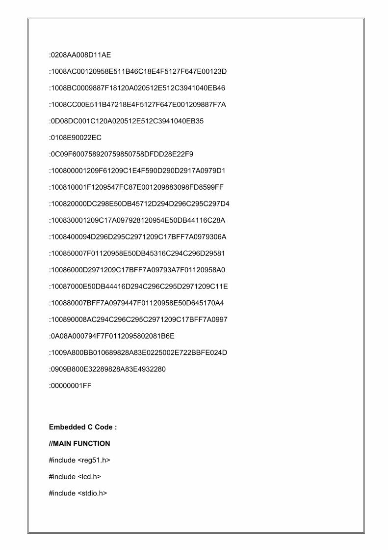
:0208AA008D11AE
:1008AC00120958E511B46C18E4F5127F647E00123D
:1008BC0009887F18120A020512E512C3941040EB46
:1008CC00E511B47218E4F5127F647E001209887F7A
:0D08DC001C120A020512E512C3941040EB35
:0108E90022EC
:0C09F600758920759850758DFDD28E22F9
:100800001209F61209C1E4F590D290D2917A0979D1
:100810001F1209547FC87E001209883098FD8599FF
:100820000DC298E50DB45712D294D296C295C297D4
:100830001209C17A097928120954E50DB44116C28A
:1008400094D296D295C2971209C17BFF7A0979306A
:100850007F01120958E50DB45316C294C296D29581
:10086000D2971209C17BFF7A09793A7F01120958A0
:10087000E50DB44416D294C296C295D2971209C11E
:100880007BFF7A0979447F01120958E50D645170A4
:100890008AC294C296C295C2971209C17BFF7A0997
:0A08A000794F7F0112095802081B6E
:1009A800BB010689828A83E0225002E722BBFE024D
:0909B800E32289828A83E4932280
:00000001FF
Embedded C Code :
//MAIN FUNCTION
#include <reg51.h>
#include <lcd.h>
#include <stdio.h>
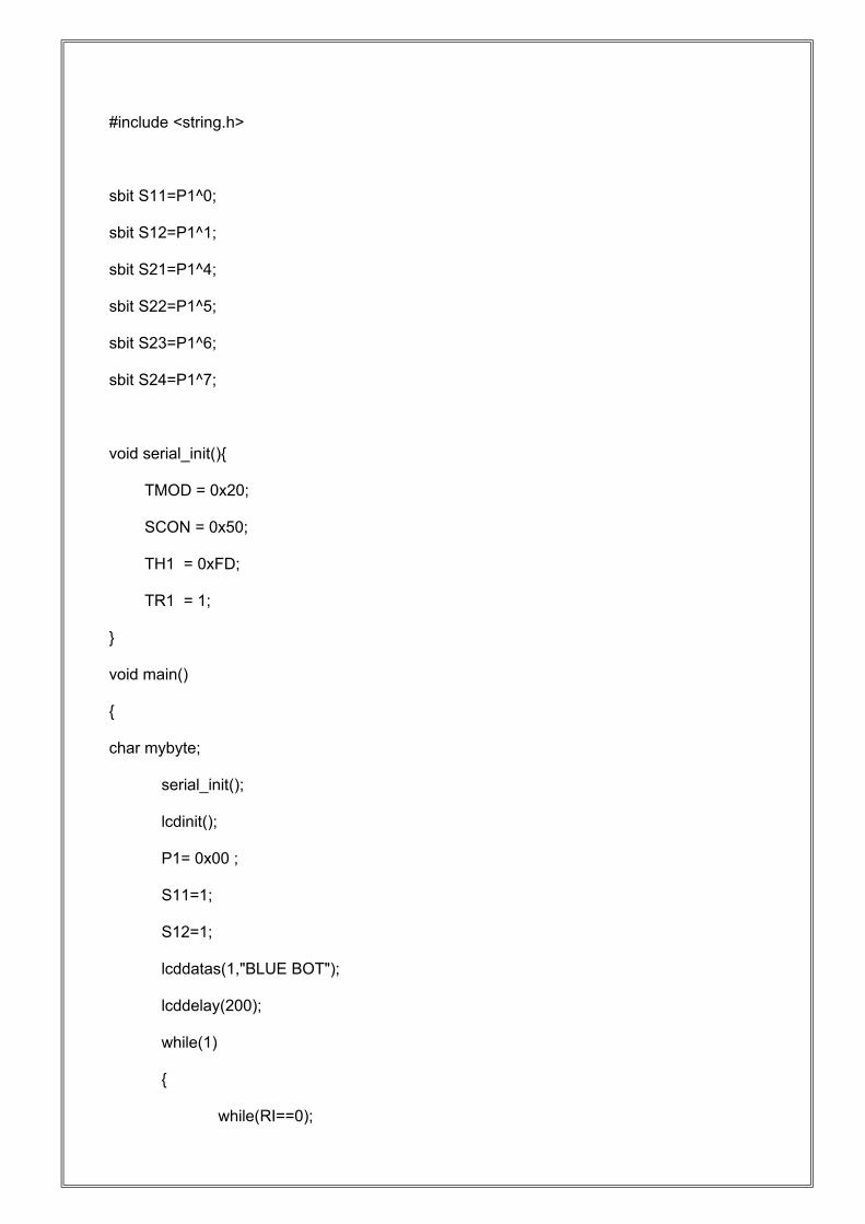
#include <string.h>
sbit S11=P1^0;
sbit S12=P1^1;
sbit S21=P1^4;
sbit S22=P1^5;
sbit S23=P1^6;
sbit S24=P1^7;
void serial_init(){
TMOD = 0x20;
SCON = 0x50;
TH1 = 0xFD;
TR1 = 1;
}
void main()
{
char mybyte;
serial_init();
lcdinit();
P1= 0x00 ;
S11=1;
S12=1;
lcddatas(1,"BLUE BOT");
lcddelay(200);
while(1)
{
while(RI==0);
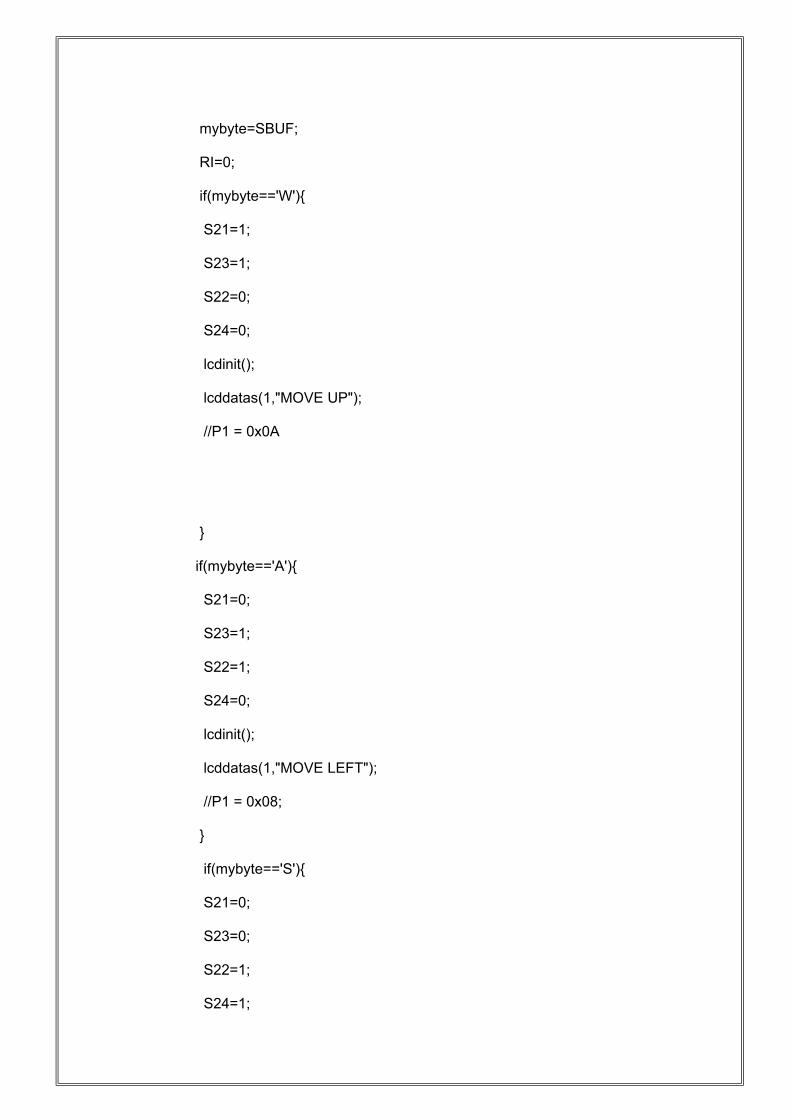
mybyte=SBUF;
RI=0;
if(mybyte=='W'){
S21=1;
S23=1;
S22=0;
S24=0;
lcdinit();
lcddatas(1,"MOVE UP");
//P1 = 0x0A
}
if(mybyte=='A'){
S21=0;
S23=1;
S22=1;
S24=0;
lcdinit();
lcddatas(1,"MOVE LEFT");
//P1 = 0x08;
}
if(mybyte=='S'){
S21=0;
S23=0;
S22=1;
S24=1;
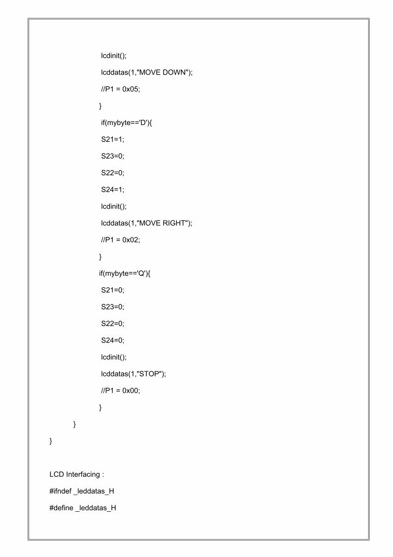
lcdinit();
lcddatas(1,"MOVE DOWN");
//P1 = 0x05;
}
if(mybyte=='D'){
S21=1;
S23=0;
S22=0;
S24=1;
lcdinit();
lcddatas(1,"MOVE RIGHT");
//P1 = 0x02;
}
if(mybyte=='Q'){
S21=0;
S23=0;
S22=0;
S24=0;
lcdinit();
lcddatas(1,"STOP");
//P1 = 0x00;
}
}
}
LCD Interfacing :
#ifndef _leddatas_H
#define _leddatas_H
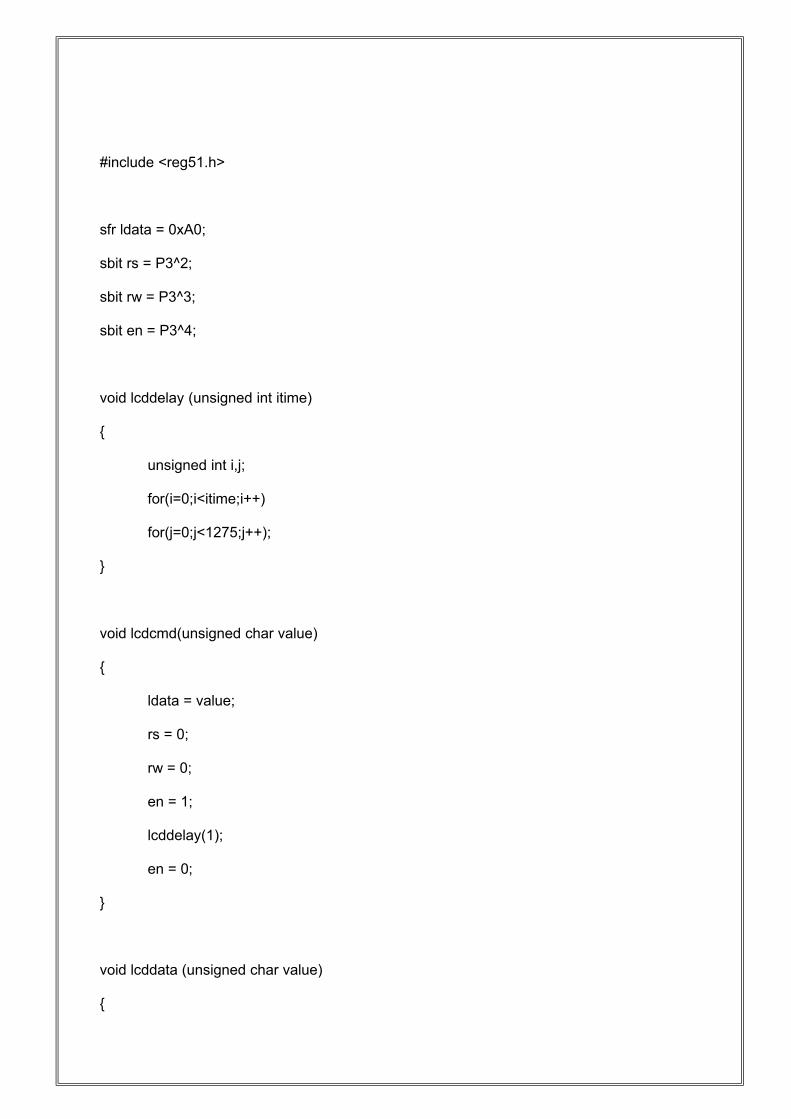
#include <reg51.h>
sfr ldata = 0xA0;
sbit rs = P3^2;
sbit rw = P3^3;
sbit en = P3^4;
void lcddelay (unsigned int itime)
{
unsigned int i,j;
for(i=0;i<itime;i++)
for(j=0;j<1275;j++);
}
void lcdcmd(unsigned char value)
{
ldata = value;
rs = 0;
rw = 0;
en = 1;
lcddelay(1);
en = 0;
}
void lcddata (unsigned char value)
{
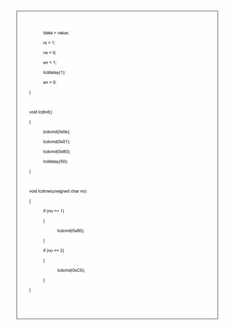
ldata = value;
rs = 1;
rw = 0;
en = 1;
lcddelay(1);
en = 0;
}
void lcdinit()
{
lcdcmd(0x0e);
lcdcmd(0x01);
lcdcmd(0x80);
lcddelay(50);
}
void lcdrow(unsigned char no)
{
if (no == 1)
{
lcdcmd(0x80);
}
if (no == 2)
{
lcdcmd(0xC0);
}
}
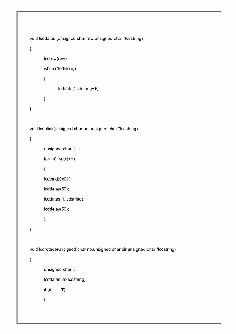
void lcddatas (unsigned char row,unsigned char *lcdstring)
{
lcdrow(row);
while (*lcdstring)
{
lcddata(*lcdstring++);
}
}
void lcdblink(unsigned char no,unsigned char *lcdstring)
{
unsigned char j;
for(j=0;j<no;j++)
{
lcdcmd(0x01);
lcddelay(50);
lcddatas(1,lcdstring);
lcddelay(50);
}
}
void lcdrotade(unsigned char no,unsigned char dir,unsigned char *lcdstring)
{
unsigned char i;
lcddatas(no,lcdstring);
if (dir == 'l')
{
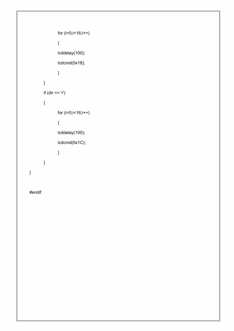
for (i=0;i<16;i++)
{
lcddelay(100);
lcdcmd(0x18);
}
}
if (dir == 'r')
{
for (i=0;i<16;i++)
{
lcddelay(100);
lcdcmd(0x1C);
}
}
}
#endif
CONCLUSION
Wireless control is one of the most important basic needs for all living beings. But unfortunately due to a huge amount of data and communication overheads the technology is not fully utilized.
1 Many of the wireless-controlled robots use RF modules. But this project make use of Android mobile phone for robotic control which is very cheap and easily available. The control commands available are more than RF modules. For this the android mobile user has to install an application on her/his mobile. Then user needs to turn on the Bluetooth in the mobile. The wireless communication techniques used to control the robot is Bluetooth technology. User can use various commands like move forward, reverse, move left, move right using these commands which are sent from the Android mobile. Robot has a Bluetooth receiver unit which recives the commands and give it to the microcontroller circuit to control the motors. The microcontroller then transmits the signal to the motor driver IC’s to operate the motors
FUTURE SCOPE
This project will be further implemented on platform like AVR, ARM microcontroller etc.
More can be done in the process of UART communication control and many challenges will be carry out to increase reliability and efficiency.
This system also can be developed by using GSM technology.
REFERENCES
Books:
THE 8051 MICROCONTROLLER&EMBEDDED SYSTEMS:-ByMuhammad Ali Mazidi Janice Gillispie Mazidi Rolino D.Mckinlay References on the Web:
www.engineers garage.com www.instructable.comwww.atmel.comwww.wikipedia.com