ANDHRA PRADESH CODE OF TECHNICAL INTERFACEtserc.gov.in/file_upload/uploads/Acts and Polices/Policies...
27
3/26/2014 APERC - Grid Code http://www.aperc.gov.in/Guidelines/Connectioncode.html 1/27 ANDHRA PRADESH CODE OF TECHNICAL INTERFACE Section 3 CONNECTION CODE Table of Contents 3.1 Procedu re f o r Application for Connection 3.1.1 Us e rs 3.1.2 Licen s ee 3.1.3 Op t imal Connection Locations 3.1.4 Data from APTRANSCO 3.1.5 A p p lication for Connection 3.1.6 Ac c e ptance or R ejection 3.1.7 Conn e ction Agreement 3.1.8 Da t a Exchange 3.1.9 No n -A c ceptable Offers 3.2 Connection C onditions 3.2.1 Intr o duction 3.2.2 Objectiv e s 3.2.3 Co n nection Agreements 3.2.4 C o n nection Site M a tters 3.2.5 Syst e m Perfor m ance 3.2.6 C o n n e c tion Point 3.2.7 Da t a R e quire m ents 3.3 Under F r equency Relays 3.4 Grid Cha r ac t e r isti c s
Transcript of ANDHRA PRADESH CODE OF TECHNICAL INTERFACEtserc.gov.in/file_upload/uploads/Acts and Polices/Policies...

3/26/2014 APERC - Grid Code
http://www.aperc.gov.in/Guidelines/Connectioncode.html 1/27
ANDHRA PRADESH
CODE OF TECHNICAL INTERFACE
Section 3
CONNECTION CODE
Table of Contents
3.1 Procedure for Application for Connection
3.1.1 Users
3.1.2 Licensee
3.1.3 Optimal Connection Locations
3.1.4 Data from APTRANSCO
3.1.5 Application for Connection
3.1.6 Acceptance or Rejection
3.1.7 Connection Agreement
3.1.8 Data Exchange
3.1.9 Non-Acceptable Offers
3.2 Connection Conditions
3.2.1 Introduction
3.2.2 Objectives
3.2.3 Connection Agreements
3.2.4 Connection Site Matters
3.2.5 System Performance
3.2.6 Connection Point
3.2.7 Data Requirements
3.3 Under Frequency Relays
3.4 Grid Characteristics

3/26/2014 APERC - Grid Code
http://www.aperc.gov.in/Guidelines/Connectioncode.html 2/27
3.4.1 Introduction
3.4.2 Objective
3.4.3 Implementation
3.4.4 Voltage Criteria
3.4.5 Frequency
3.4.6 Reliability Criteria
3.4.7 Harmonic Distortion
3.4.8 Voltage Flicker
3.5 Connected Plant Restrictions
3.5.1 General Principle
3.5.2 Safety
3.5.3 Insulation
3.5.4 Clearances
3.5.5 Earthing
3.5.6 Safety Training
3.5.7 Motor Starting
3.5.8 Access to APTRANSCO
3.5.9 Unintended and Unscheduled back-energization
3.5.10 Harmonics )Harmonic Current Generated byConsumers)
3.5.11 Voltage Flicker Generated by Users
3.5.12 Power Factor
3.6 Operational Numbering and Nomenclature Standards
3.6.1 Introduction
3.6.2 Objective
3.6.3 Procedure for Number and nomenclature of plant andapparatus at connection sites
3.7 Protection Requirements & Co-ordination
3.7.1 General Principles
3.7.2 Fault Clearance Times
3.7.3 Protection Requirements
3.8 Earthing
3.9 Design Parameters of New Generating Units

3/26/2014 APERC - Grid Code
http://www.aperc.gov.in/Guidelines/Connectioncode.html 3/27
3.10 Operational Metering
Appendix-A General Format of Site Responsibility Schedule
Appendix-B Specifications of Under Frequency Relays
CONNECTION CODE
3.1 Procedure For Application For Connection
3.1.1 Users
Any User seeking to establish new or modified arrangements for Connection to and/or use of the
Transmission System shall follow the procedures laid out in this Code.
3.1.2 Licensee
The Licensee (APTRANSCO) shall follow the procedures and time limits specified in this Code in
processing the application, making or modifying an offer and rejecting an offer.
3.1.3 Optimal Connection Locations
APTRANSCO shall publish annually before 31st March, a list of points which are technically optimal
connection locations where generators and suppliers can connect their systems to APTRANSCOsystem.
3.1.4 Data from APTRANSCO
Any prospective user or existing user wishing capacity enhancement may after studying the Long TermPlan and the Statement of Opportunity published by APTRANSCO may request APTRANSCO formore information. APTRANSCO shall furnish the data equired within 15 days of requisition.
APTRANSCO may refuse to furnish the data if it considers the data is confidential and is not requiredfor the business of the prospective user. APTRANSCO may charge reasonable cost for supplying the
data.
3.1.5 Application for Connection
Any User seeking use of the Transmission system may submit an Application for connection to
APTRANSCO in Format developed by APTRANSCO.
3.1.6 Acceptance or Rejection
APTRANSCO shall either accept or reject the application within 30 days from the date of Application. If rejected, APTRANSCO shall communicate the reasons. If APTRANSCO requires additional data
from the Applicant the last date for acceptance or rejection may be extended by another month from the
date of submission of the additional information. The additional data shall be furnished to APTRANSCOwithin 15 days from the date requisitioned. If the additional information is not received by
APTRANSCO within 15 days, it can either reject the Application or extend the date.
3.1.7 Connection Agreement
If the Application is accepted then APTRANSCO and the user shall proceed to finalise a Connection

3/26/2014 APERC - Grid Code
http://www.aperc.gov.in/Guidelines/Connectioncode.html 4/27
Agreement as per para 3.2.3.
3.1.8 Data Exchange
The data exchange between APTRANSCO and users shall be in accordance with the provisions of the
Planning code.
3.1.9 Non-Acceptable Offers
In the event of the offer becoming invalid or not being accepted by any User within the validity period,
no further action shall be taken by the APTRANSCO on the Connection applications.
3.2 Connection Conditions
3.2.1 Introduction
Connection Conditions specify the technical, design and operational criteria which must be complied
with by any User connected to the Transmission System.
3.2.2 Objectives
The objective of this Section is to ensure the following:
(i) All Users or prospective Users are treated equitably.(ii) Any new Connection shall not impose any adverse effects on existing Users, nor shall a new
Connection suffer adversely due to existing Users.
(iii) By specifying minimum design and operational criteria, to assist Users in their requirement to complywith License obligations and hence ensure that a system of acceptable quality is maintained.
(iv) The ownership and responsibility for all items of equipment is clearly specified in a schedule (Site
Responsibility Schedule) for every site where a Connection is made.
3.2.3 Connection Agreements
A Connection Agreement shall be drawn up specifying the general conditions for connection and any
specific conditions, both technical and financial, applicable to that connection.
If the design parameters based on which the original offer was made, have changed, APTRANSCO
shall make a revised offer to the User including revised terms and extended time limit for submission of
data. This revised offer shall form the basis of any Connection Agreement.
3.2.4 Connection Site Matters
3.2.4.1 Site Responsibility Schedule
For every Connection to the Transmission System for which a Connection Agreement is
required, a schedule of equipment shall be prepared by APTRANSCO with informationsupplied by the respective Users. This shall include:
· Schedule of HV Apparatus
· Schedule of Plant, LV/MV Apparatus, services and supplies
· Schedule of telecommunications and measurements Apparatus
· The safety rules which apply to each Plant/Apparatus
A Site responsibility Schedule, shall state the following for each item of equipment installed at theConnection Site:
(i) The ownership of equipment.

3/26/2014 APERC - Grid Code
http://www.aperc.gov.in/Guidelines/Connectioncode.html 5/27
(ii) The responsibility for control of equipment.
(iii) The responsibility for maintenance of equipment.
(iv) The responsibility for operation of equipment.(v) The manager of the site.
(vi) The responsibility for all matters relating to safety of persons at site.
(vii) The responsibility for all matters relating to safety of equipment at site.
All H.V. Apparatus on any connection site shall be shown on one diagram which shall include
details of the following.
1. Bus bars2. Circuit Breakers
3. Isolators
4. Bypass facilities
5. Earthing switches6. Maintenance of Earths
7. Overhead line entries
8. Overhead line tappings
9. Cable and Cable Sealing ends10. Generating Unit
11. Generating Unit Transformers
12. Generation unit auxiliary transformers including lower voltage circuit breakers13. Station Service Transformers including lower voltage circuit breakers
14. Capacitors including synchronous compensators
15. Series and shunt reactors.
16. Grid Transformers (Inter Connecting transformers)17. Tertiary windings
18. Earthing and Auxiliary Transformers
19. 3f Voltage transformers
20. 1f Voltage transformers with phase identity21. Surge Arresters
22. Neutral earthing arrangements on HV plant
23. Current transformers
The User owning the Connection site shall provide reasonable access and other required
facilities to another User whose equipment is installed at the Connection site for installation,
operation and maintenance, etc.
Each Connection point shall be precisely shown.
An illustrative Site Responsibility Schedule is provided in the Appendix to this Section.
3.2.4.2 Site Common Drawings
Site Common Drawings shall be prepared by the owner Company (APTRANSCO or Users)
using the information furnished by the other Company (User or APTRANSCO) containing the
following information:
(i) Connection Site Equipment layout
(ii) Electrical Layout

3/26/2014 APERC - Grid Code
http://www.aperc.gov.in/Guidelines/Connectioncode.html 6/27
(iii) Common Protection and Controls
(iv) Common Services.
SCDs are updated by the request and initiation of either company but the responsibility of
updating at every change lies with the site owner.
3.2.4.3 Maintenance at Connection Site
The User’s equipment at the APTRANSCO’s site shall be maintained promptly and properly by
the User and vice versa so that the equipment and personnel of the site owner are not
jeopardised by the neglect of the other Company.
3.2.4.4 Site Operational Procedures
APTRANSCO and User must make available staff to take necessary safety procautions and
carryout operational duties at the Site. The written operating and safely instructions must be
available at the site.
3.2.5 System Performance
(a) All equipment connected to the Transmission System shall be of such design and construction
as to satisfy the requirements of the relevant Indian Standard Specification. Where no BISexists, the appropriate IEC Standard or equivalent International Standard will apply.
(b) Installation of all electrical equipment shall comply with IE Rules
(c) For every new Connection sought, the APTRANSCO shall specify the Connection Point andthe voltage to be used, along with the metering and protection requirements as specified in the
Metering and Protection Sections.
(d) The Transmission System frequency shall be in accordance with the Grid CharacteristicsSection. The User shall however be subject to the grid discipline prescribed by SLDC/
SRLDC as per guidelines mutually agreed with SREB/ SRLDC.
(e) Voltage variation on the Transmission System shall be in accordance with the Grid
Characteristics Section.
(f) Insulation co-ordination of the Users’ equipment shall conform to applicable IndianStandards/Codes. Rupturing capacity of switchgear shall not be less than that specified by
APTRANSCO.
(g) Protection and Metering schemes shall be as detailed in the Protection Section of the Code.
For existing Power Stations, the equipment for data transmission and communications shall be
owned and maintained by the APTRANSCO, unless alternative arrangements are mutually
agreed.
For new Power Stations the equipment for data transmission and communications shall beowned and maintained by the respective Generator.
(h) The new Generating units to be connected to the Grid shall be capable of increasing the output
by 5% instantaneously upto 105% MCR for a minimum of 5 minutes.
(i) The new Generating units shall have AVR and turbine speed governor with overall droop of 3 to
6%.
3.2.6 Connection Point
3/26/2014 APERC - Grid Code
http://www.aperc.gov.in/Guidelines/Connectioncode.html 7/27
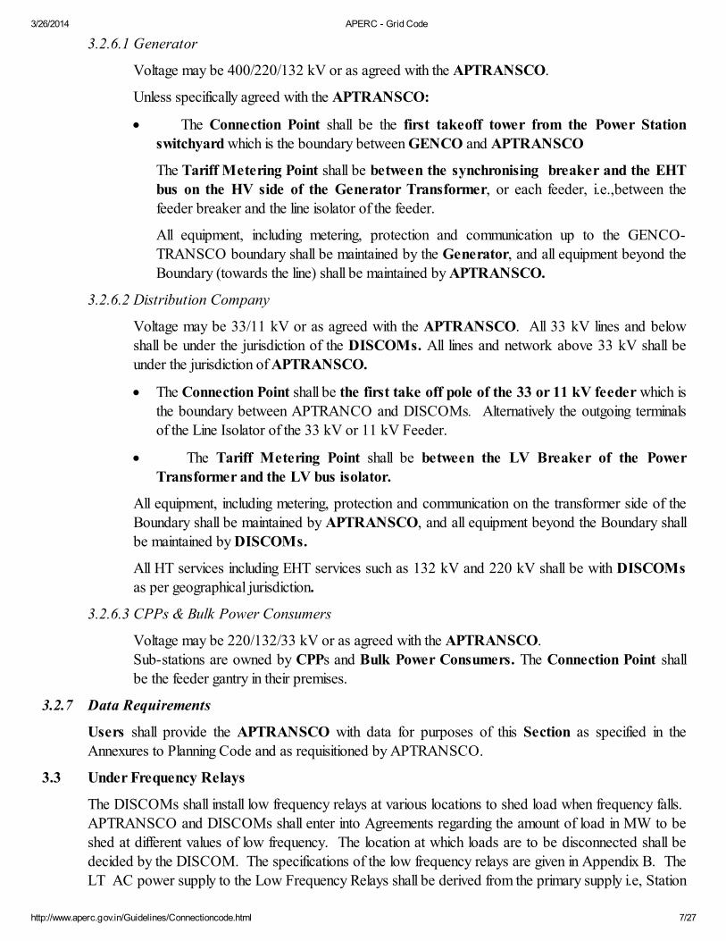
3.2.6.1 Generator
Voltage may be 400/220/132 kV or as agreed with the APTRANSCO.
Unless specifically agreed with the APTRANSCO:
· The Connection Point shall be the first takeoff tower from the Power Station
switchyard which is the boundary between GENCO and APTRANSCO
The Tariff Metering Point shall be between the synchronising breaker and the EHT
bus on the HV side of the Generator Transformer, or each feeder, i.e.,between the
feeder breaker and the line isolator of the feeder.
All equipment, including metering, protection and communication up to the GENCO-
TRANSCO boundary shall be maintained by the Generator, and all equipment beyond the
Boundary (towards the line) shall be maintained by APTRANSCO.
3.2.6.2 Distribution Company
Voltage may be 33/11 kV or as agreed with the APTRANSCO. All 33 kV lines and below
shall be under the jurisdiction of the DISCOMs. All lines and network above 33 kV shall beunder the jurisdiction of APTRANSCO.
· The Connection Point shall be the first take off pole of the 33 or 11 kV feeder which isthe boundary between APTRANCO and DISCOMs. Alternatively the outgoing terminals
of the Line Isolator of the 33 kV or 11 kV Feeder.
· The Tariff Metering Point shall be between the LV Breaker of the Power
Transformer and the LV bus isolator.
All equipment, including metering, protection and communication on the transformer side of the
Boundary shall be maintained by APTRANSCO, and all equipment beyond the Boundary shall
be maintained by DISCOMs.
All HT services including EHT services such as 132 kV and 220 kV shall be with DISCOMsas per geographical jurisdiction.
3.2.6.3 CPPs & Bulk Power Consumers
Voltage may be 220/132/33 kV or as agreed with the APTRANSCO.
Sub-stations are owned by CPPs and Bulk Power Consumers. The Connection Point shall
be the feeder gantry in their premises.
3.2.7 Data Requirements
Users shall provide the APTRANSCO with data for purposes of this Section as specified in the
Annexures to Planning Code and as requisitioned by APTRANSCO.
3.3 Under Frequency Relays
The DISCOMs shall install low frequency relays at various locations to shed load when frequency falls.
APTRANSCO and DISCOMs shall enter into Agreements regarding the amount of load in MW to be
shed at different values of low frequency. The location at which loads are to be disconnected shall bedecided by the DISCOM. The specifications of the low frequency relays are given in Appendix B. The
LT AC power supply to the Low Frequency Relays shall be derived from the primary supply i.e, Station

3/26/2014 APERC - Grid Code
http://www.aperc.gov.in/Guidelines/Connectioncode.html 8/27
Auxiliary Transformer but not from the external public distribution system.
3.4 Grid Characteristics
3.4.1 Introduction
This section specifies the electrical parameters of performance of the GRID which affect the performance
of connected Users and other transmission systems interconnected with the AP Transmission Grid.
3.4.2 Objective
(i) To ensure that the GRID performance meets a minimum standard which is essential for the
Users’ system and equipment to function properly.
(ii) To enable Users to design their systems and equipment to suit the electrical environment that they
operate in.
(iii) To enhance the quality standards of the AP Electrical System towards standards stipulated in or
established under the authority of National and State Acts and Rules in the short term and
gradually moving towards international standards in the long term.
3.4.3 Implementation
The GRID performance standards established herein shall be implemented in a manner so as to ensure
that no entities are forced to achieve goals beyond the capability and limitations of the current system in
the immediate future while continuing to strive for the higher standards by improving their system in the
long term.
To this end, the CTI shall be implemented in three Stages:
Preliminary Stage:
The time period immediately following approval of the first version of the CTI by APERC. Existing
conditions to prevail. However all entities shall endeavour to minimise the duration of the Preliminary
Stage.
Transition Stage:
An agreed time period during which improvements are made to the system with the injection ofinvestment capital.
Final Stage:
An agreed time period when substantial improvements have been carried out and the system is
considered to be in satisfactory condition with the needed capital investment.
Standards for different Stages will be different.
The length of the Preliminary Stage and Transition Stage shall be determined by the Regulator who willinform all parties concerned of impending change to the next stage at least six months in advance.
3.4.4 Voltage Criteria
The voltage criteria detailed below are the target values to be achieved under the leadership of
APTRANSCO, in coordination with SRLDC and with the cooperation of the Power Sector Utilities in
Andhra Pradesh State.
3.4.4.1 Voltage Variations (CEA Standards)

3/26/2014 APERC - Grid Code
http://www.aperc.gov.in/Guidelines/Connectioncode.html 9/27
System Voltage
Maximum(RMS)
Minimum(RMS)
400 kV 420 kV 360 kV
220 kV 245 kV 200 kV
132 kV 145 kV 120 kV
3.4.4.2 Voltage Unbalance
The phase voltages of a 3-phase supply should be of equal magnitude and 120o apart in phase
angle. Deviations will result in decreased efficiency, negative torque, vibrations and overheating.
Severe unbalance could lead to malfunctioning of some equipment. Voltage unbalance is defined
as:
Voltage Unbalance = Deviation between highest and lowest phases
Average voltage of three phases
Limits for voltage unbalance are:
220kV and above: 2%
Below 220 kV: 3%
Balancing loads on individual phases will help greatly in avoiding unbalanced voltages
3.4.5 Frequency
Frequency of the transmission system should be maintained within an acceptable range to ensure proper
operation of the system. Insofar as possible, APTRANSCO shall fulfil its parrtial responsibility to enable
SRLDC to keep the frequency within acceptable ranges and avoid the periods where the frequency
values given under “Extreme Conditions” prevail.
TABLE
Frequency Limits
SREB Standards : “targets” to be achieved:
Upper limit: 50.5 Hz
Lower limit 49.5 Hz
Statutory Limits : acceptable
Upper limit: 51.5 Hz
Lower limit: 48.5 Hz
Extreme Conditions:
Upper limit: 52.5 Hz
Lower limit 47.5 Hz
3.4.5.1 All new generating units shall be capable of operation in 47.5 to 51.0 Hz frequency range forshort duration without damage or reduction of life.

3/26/2014 APERC - Grid Code
http://www.aperc.gov.in/Guidelines/Connectioncode.html 10/27
3.4.6 Reliability Criteria
System reliability of the GRID includes three aspects:
· system adequacy
· system security.
· service reliability
3.4.6.1 Generation Adequacy
Adequacy is the ability of the electric system to supply the aggregate electrical demand and
energy requirements of their customers at all times, taking into account scheduled and
reasonably expected unscheduled outages of system elements.
Adequacy of the generating system is usually measured in terms of loss of load probability(LOLP) which is the probability of system capacity not being able to meet system load. LOLP
can also be expressed as loss of load expectation (LOLE) in days per year. This measure does
not consider the amount or duration of the capacity shortfall.
System Adequacy Limits:
Preliminary Stage: 20%
Transition Stage: 8%
Final Stage: 1% (87.6 hr/year)
3.4.6.2 Security
Security is the ability of the electric system to withstand sudden disturbances such as electric
short circuits or unanticipated loss of system elements.
The bulk electric system shall be designed for a security level of n-1, i.e.to withstand a single
contingency with little negative effect. This means the most severe fault or the tripping of a critical
generator, transformer or line should not result in
a) instability of the system
b) overloading lines and/or transformers for more than 15 minutes
c) voltage drop of more than 10 % when the system import is increased by 20%
d) load shedding
System Security Limits:
Security level of “n-1” (single contingency) PLUS
spinning reserve margin of:Preliminary Stage: no mandatory requirement
Transition Stage: 0.5 % of system peak load
Final Stage: 1 % of system peak load
3.4.6.3 Service Reliability
The points where electric power is supplied from the transmission system to the Users
(distribution companies, another transmission system, EHT customers) are called delivery pointsor grid supply points. Outages at these points directly affect the Users of the GRID. The
reliability level at the delivery points is therefore an indication of the quality of service provided
by APTRANSCO to its Users.

3/26/2014 APERC - Grid Code
http://www.aperc.gov.in/Guidelines/Connectioncode.html 11/27
Service reliability of the GRID is indicated by :
System Average Interruption Frequency Index (SAIFI)
System Average Interruption duration Index (SAIDI)
which are calculated as follows:
For each forced outage involving one or more delivery points and lasting more than 1 minute, the
following parameters are recorded:
Ø Duration of outage in minutes: Ti (min)
Ø Sum of interrupted loads at all affected delivery points: S Pi (kVA)
SAIFI = SPi / Ptotal
SAIDI= S(Pi x Ti)/Ptotal ¸ 60
Where Ptotal = total sum of installed load at all delivery points
Note: Scheduled outages which are communicated to the consumers beforehand and load
shedding due to capacity shortage are not counted in the computation of these indices
Allowable Limits
SAIFI SAIDI
Preliminary Stage no limit no limit
Transition Stage 24/yr 10 hours/year
Final Stage 18/yr 8 hours / year
3.4.7 Harmonic Distortion
3.4.7.1 General Description
Many types of equipment and phenomena can produce voltages and currents at frequencies that
are multiples of the power frequency. These high frequency components are called harmonics
and their ratio to the fundamental frequency is the harmonic order. Harmonics have manynegative effects on the system and connected loads, so they have to be limited to a manageable
level.
Control of harmonics on the APTRANSCO system is based on voltage harmonic distortion.
Users produce harmonics by drawing from and injecting into the system harmonic currents which
propagate through the system creating harmonic voltage drops, thus affecting others, so control
of User harmonics is based on harmonic distortion current.
Harmonics are grouped into three categories: odd triplens (multiples of three), other odd
harmonics, and even harmonics, with different severity levels and effects on equipment for each
category. Odd harmonics are much more common than even harmonics.
3.4.7.2 Indicator of Quality for System Harmonics
Harmonic contents of the supply voltage is indicated by the following indices:
VTHD =

3/26/2014 APERC - Grid Code
http://www.aperc.gov.in/Guidelines/Connectioncode.html 12/27
VIHD = Where Vi : ith harmonic of voltage
V1 : fundamental frequency (50 Hz) voltage
VTHD: voltage total harmonic distortion
VIHD : voltage distortion of ith harmonic
3.4.7.3 Maximum Limits of Voltage Harmonic Distortion in HT and EHTSystems.
Table
Harmonic Order Distortion %
HT EHT
(odd, non-triplen)57
1113
1719
2325>25
6.05.0
3.53.0
2.01.5
1.51.50.2+1.3x25/n
2.02.0
1.51.5
1.01.0
1.00.70 .1+0.6x25/n
(odd, triplen)39
1521
>21
5.01.5
0.30.3
0.2
2.01.0
0.30.2
0.2
(even)2
46
81012
>12
2.0
1.00.5
0.50.50.2
0.2
2.0
2.00.5
0.40.40.2
0.2
Total Harmonic
Distortion
8%
3%
3.4.7.4 Control and Measurement

3/26/2014 APERC - Grid Code
http://www.aperc.gov.in/Guidelines/Connectioncode.html 13/27
(a) Control
APTRANSCO shall monitor the voltage harmonic levels at the supply points to the
Users (DISCOMs, AP Genco, major users) and other strategic locations on thetransmission system.
APTRANSCO will compile a list of all metering points and take measurements at 5 sites
per month. The list has to be submitted to APERC for approval.
(b) Measurement
The measurements should conform to IEC Std 1000-4-7 or IEEE Std 519. Themeasurements should be taken at 10 minute intervals and should last for 1 week per site.
3.4.7.5 Enforcement of Limits
The harmonic voltage limits will be implemented in stages as follows
Preliminary Stage
Limits not in effect
Transition Stage
APTRANSCO will monitor voltage harmonic distortions at all delivery points, but no sanctions
will apply for exceeding the limits
Final Stage
The limits in Section 3.4.7.3 will apply
Limits of Supply Voltage Harmonics in LT System will be included in future Versions.
3.4.8 Voltage Flicker
3.4.8.1 General Description
If the voltage fluctuates, the luminous intensity of the lamps and TV’s will fluctuate
correspondingly. If the fluctuation is of a magnitude and frequency perceptible to the eye, itbecomes flicker. Flicker could range from annoying to complete interference of normal activity.
Flicker is not usually produced by the power system but by customer loads such as arc furnaces,compressors, starting of large motors, etc. Since voltage fluctuation of the system affects otherusers on the same system, the transmission company needs to control the flicker on its lines and
station busses. At the same time, flicker-generating loads connected to the system have to becontrolled.
3.4.8.2 Indicator of Quality for System Flicker
Flicker is measured by means of two indices, Pst and Plt, as defined in IEC Std 1000-3-7. For
the purpose of regulation, Pst, the short term flicker severity index, is selected as the indicator of
quality.
3.4.8.3 Limits
Pst = 1, which is equivalent to the threshold of perception, is the allowable level of flicker on the
transmission system.
3/26/2014 APERC - Grid Code
http://www.aperc.gov.in/Guidelines/Connectioncode.html 14/27
3.4.8.4 Control and Measurement
Substations which supply heavy industrial loads such as furnaces, steel mills, etc. are targets forflicker monitoring. Other substations and connection points will be selected for monitoring on arandom basis. At least one site is monitored each month.
The list of monitoring points is submitted to APERC for approval at least 2 months before the
monitoring. The flicker measurement will be conducted at 10 minute intervals according toprocedures outlined in IEC Std 61000-4-15. Each site is measured for 1 week
3.4.8.5 Enforcement of Limits
Flicker limits and control and measurement procedure will be in effect only in the Final Stage
3.5 Connected Plant Restrictions
3.5.1 General Principle
Users connected to the Grid can produce power disturbances which propagate to the power system. If
these disturbances are severe, the power system and other Users on the system will be adverselyaffected. To ensure system integrity and fairness to all Users restrictions and controls have to be placedon Users of the system.
3.5.2 Safety
The term "Safety" refers to safety standards adopted in manufacture, erection stages in choice of location
and in installation, operation and maintenance procedures. The term applies both to safety to equipmentand safety to persons including safety of general public (in addition to safety of utility staff).
The equipment of the Users, including machines, devices, overhead lines, underground cables,transformers, etc., must conform to Safety Standards (ISS, general engineering safety standards and thesafety Codes to be issued by APTRANSCO). The Standards of the Safety Codes to be issued by
APTRANSCO shall not be lower than, or inferior to, the APSEB Safety Manual.
3.5.3 Insulation
The Users' system must be designed with the proper basic insulation level (BIL). Insulation of allcomponents in service must have adequate dielectric strength for the system operating voltages at all
times.
3.5.4. Clearances
All overhead lines, equipment and facilities of the User’s system connected to the GRID must comply
with clearance limits published in the Indian Electricity Rules. For situations not covered in the IndianElectricity Rules, the IEEE C2-1997 “National Electrical Safety Code” will apply.
3.5.5 Earthing
All components of the Users' systems must be properly earthed as per standards. All individual earthelectrodes, earthing pits, and the interconnection arrangements shall be as per standards and shall be
properly maintained.
The bodies/cases/trucks/enclosures of all items of equipment shall be properly earthed, with the actual
earthing arrangements depending on the machine ratings. Metallic supports of overhead lines and cable
3/26/2014 APERC - Grid Code
http://www.aperc.gov.in/Guidelines/Connectioncode.html 15/27
sheaths and shields shall also be earthed as appropriate.
3.5.6 Safety Training
Personnel of all entities shall be adequately trained in the correct operating techniques and safetyprecautions, keeping in mind cross-boundary connections.
3.5.7 Motor Starting
The Motor Starting Current of motors in the Users' systems shall be less than 6 times the full-load current
unless special exemption is granted. The appropriate methods of motor starting shall be adopted. Twoor more motors shall not be started simultaneously or within 5 minutes if the resulting voltage dip at the
substation bus exceeds 5 %.
Where necessary, APTRANSCO shall have the right to advise the consumer or User to change over to"auto-transformer" motor starting if the existing starting method causes unacceptable system distortions.
3.5.8 Access to APTRANSCO
APTRANSCO and its authorized personnel shall have the right to inspect the plant of any USER or
Consumer, to ensure conformity to standards and restrictions.
3.5.9 Unintended and Unscheduled back-energization
The Users shall take adequate precautions to ensure that no part of the grid is energized by the Users'
system from another source of supply unless it is requisitioned in writing by the utility as an exceptionalarrangement. The switch-gear and controls of the Users' systems shall be so designed as to prevent
back-energisation and the personnel shall be made aware of the need for this precaution.
3.5.10 Harmonics (Harmonic Current Generated by Consumers)
3.5.10.1 Indicators
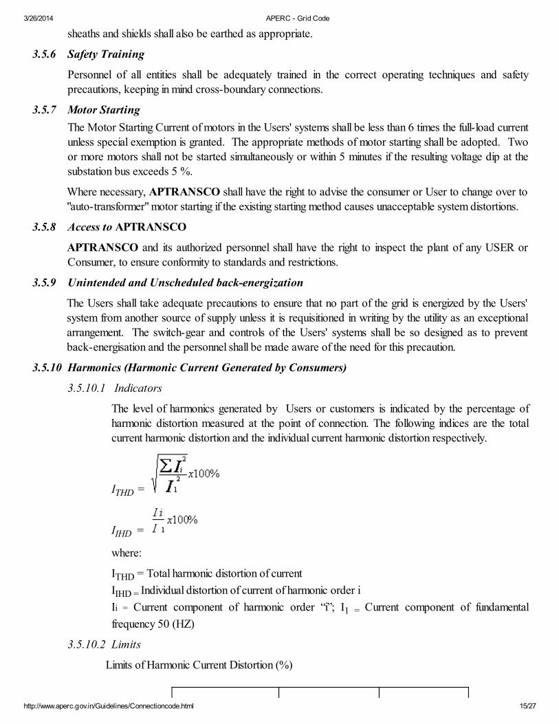
The level of harmonics generated by Users or customers is indicated by the percentage ofharmonic distortion measured at the point of connection. The following indices are the total
current harmonic distortion and the individual current harmonic distortion respectively.
ITHD =
IIHD =
where:
ITHD = Total harmonic distortion of current
IIHD = Individual distortion of current of harmonic order i
Ii = Current component of harmonic order “i”; I1 = Current component of fundamental
frequency 50 (HZ)
3.5.10.2 Limits
Limits of Harmonic Current Distortion (%)

3/26/2014 APERC - Grid Code
http://www.aperc.gov.in/Guidelines/Connectioncode.html 16/27
Harmonic Order
(n)
P > 10 kW or
V< 33 kV
P>50 kW or
V>33 kV
Odd, Non triplen
5 12 6
7 8.5 5.1
11 4.3 2.2
13 3 2.2
17 2.7 1.8
19 1.9 1.7
23 1.6 1.1
25 1.6 1.1
>25 0.8+0.8*25/n 0.4
Triplen
3 16.6 7.5
9 2.2 2.2
15 0.6 0.8
21 0.4 0.4
> 21 0.3 0.4
Even
2 10.0 10
4 2.5 3.8
6 1.0 1.5
8 0.8 0.5
10 0.8 0.5
12 0.4 0.5
>12 0.3 0.5
Total 20.0 % 12 %
3.5.10.3 Control and Measurement
Measurements may be taken at any time by APTRANSCO at the customer’s connection
point. Measurements have to be taken in accordance with methodologies of IEC 61000-4-7or IEEE STD 519-1992 and have to be for at least 24 hours long at 10 minute measurement
intervals.
3.5.10.4 Enforcement of Limits
The customer load harmonic limits will be implemented in stages as follows:
Preliminary Stage
Limits not in effect
Transition Stage
APTRANSCO will monitor current harmonic distortions at all delivery points, but no
sanctions will apply for exceeding the limits
Final Stage

3/26/2014 APERC - Grid Code
http://www.aperc.gov.in/Guidelines/Connectioncode.html 17/27
The limits in Section 3.4.10.2 will apply
Limits of Current Harmonics in LT System will be included in future versions of CTI.
3.5.11 Voltage Flicker Generated by Users
3.5.11.1 General Description
Some customer loads draw intermittent current (e.g. arc furnace) or create a steep increase in
current (e.g. motor start). If this happens frequently and if the magnitude of current issignificant, the resulting voltage fluctuation will be sufficient to cause flicker. As an obligation to
other customers, the flicker produced by customers has to be restricted.
3.5.11.2 Indicator
Flicker generated by customers is indicated by the index Pst as defined in IEC Standard
61000-3-7 and measured with a flicker meter that meets the specification of IEC Std 868 orIEC Std 61000-4-15
3.5.11.3 Limits
Tolerance for customer-generated flicker varies with the relative strength (short circuit ratio) ofthe load and voltage level. Limits are given in the following table.
Limits of flicker produced by Users
Short Circuit Ratio
SL/SCC
Voltage
Pst
SL/SCC £ 0.04
HT 0.37
EHT 0.58
SL/SCC > 0.04
HT 0.8
EHT 1.0
3.5.11.4 Control and Measurement
Flicker is measured at the point of connection using an approved flicker meter and in
accordance with IEC Std. Measurement must be taken for at least 24 hours at 10 minutemeasurement intervals. Flicker readings with the load off must be taken for at least 5 hours asa reference.
3.5.11.5 Enforcement of Limits
Flicker limits and control and measurement procedure will be in effect only in the Final Stage
3.5.12 Power Factor
3.5.12.1 General description
It is desirable that loads on the system have power factors at or close to unity as that
represents the most efficient use of the system capability and the least loss of energy. It alsoeliminates many transient stability problems. Any load with a power factor lower than 90% is
imposing an unfair burden on the transmission system and other Users. Power Companiestherefore place restrictions on the power factors of customer loads.

3/26/2014 APERC - Grid Code
http://www.aperc.gov.in/Guidelines/Connectioncode.html 18/27
3.5.12.2 Limit
The minimum power factor allowed is 90%.
3.5.12.2 Control and Measurement
Power factor measurements are made continuously in conjunction with the voltage
measurements. Loads with inherent low power factors should automatically include capacitorsto correct the problem.
3.5.12.3 Penalty
A user with power factor worse than 90% may be refused connection to the transmissiongrid until the problem is rectified. Alternatively, a penalty may be assessed.
3.5.12.4 Enforcement of Limits
The limit for power factor shall be effective immediately.
3.5.12.5 Reactive Power Requirements: In general the Distribution Companies shall not depend onAPTRANSCO and APTRANSCO shall not depend on ISTS for reactive support.
DISCOMS shall provide reactive compensation for their systems and APTRANSCO shallprovide reactive compensation for the intra state Transmission system. The DISCOMs shallensure that consumers having inductive load install capacitors. The DISCOMs shall also install
capacitors at various locations of the Distribution System so that at the interface withAPTRANSCO the power factor is not less than 90%.
3.6 Operational Numbering and Nomenclature Standards
3.6.1 Introduction
Numbering and nomenclature of plant and apparatus at connection sites specifies responsibilities and
procedures for determining and notifying APTRANSCO and Users of the other’s plant and apparatus atconnection sites. Nomenclature shall include the selections of sub station names.
The numbering and nomenclature of plant and apparatus shall be included in the ownership diagramprepared for each connection site.
3.6.2 Objective
The objective of having numbering and nomenclature standards for plant and apparatus at connectionsites is to reduce errors in identification of plant and apparatus by ensuring that every item of plant and /
or apparatus has a unique identifying number and nomenclature agreed to and notified betweenAPTRANSCO and Users; thus improving efficiency of operation and safety.
3.6.3 Procedure for numbering and nomenclature of plant and apparatus at connection sites.
3.6.3.1 Plant and apparatus of new connection sites
When APTRANSCO or a User intends to install an apparatus at a new connection site, theproposed numbering and nomenclature shall be notified as part of the production of theownership diagram or operation diagram in accordance with the provisions of the connection
conditions. The principles to apply will be those set out in this Section.
3.6.3.2 Existing connection sites
a) When APTRANSCO or a User intends to install plant and / or apparatus at an existing

3/26/2014 APERC - Grid Code
http://www.aperc.gov.in/Guidelines/Connectioncode.html 19/27
connection site the proposed numbering and / or nomenclature to be adopted shall benotified to the other.
b) The notification shall be in writing and will consist of a revised ownership diagram
incorporating the proposed plant and numbering and nomenclature.
c) The notification shall be made at least six months prior to the proposed installation or such
shorter period as APTRANSCO or the User may agree.
d) The Recipient of the notification shall respond in writing within one month confirming receipt
and whether the proposed numbering and/or nomenclature is acceptable. If unacceptable theresponse shall state what would be acceptable.
e) In the event that agreement cannot be reached between APTRANSCO and the User,
APTRANSCO acting reasonably shall have the right to determine the numbering andnomenclature to be applied.
3.6.3.3 Changes to Existing plant and apparatus.
Where APTRANSCO or a user needs to change the existing numbering or nomenclature of any
of its plant and / or apparatus at a connection site, the provisions of 3.5.3.2 shall apply withamendments necessary to reflect that only a change is being made.
Clear Labelling: APTRANSCO and each user shall be responsible for the provision, execution
and maintenance of clear and unambiguous signs/labels showing the numbering and nomenclatureof its plant or apparatus of connection sites
3.7 Protection Requirements & Co Ordination
3.7.1 General Principles
No item of electrical equipment shall be allowed to remain connected to the Transmission System unless
it is covered by appropriate protection aimed at reliability, selectivity, speed, discrimination andsensitivity. Guidelines mentioned in protection manuals of CBI & P shall be kept in view.
Protection standards are treated as interface issues because of the possible severe cross-boundaryrepercussions of faults that occur in the system of any entity. Minimum protection requirements are
prescribed in the Section because inadequate protection or mal-operation of protection system of oneentity may result in far reaching consequences, disturbances and even damages in the systems of otherentities.
All Users shall co-operate to ensure correct and appropriate settings of protection to achieve effective,discriminatory removal of faulted equipment within the target clearance times specified in this Section.
The protection systems to be installed (or kept in service) at various Generating Stations and sub-stationsshall not be inferior to the systems existing before the effective date under the erstwhile Andhra Pradesh
State Electricity Board. The Corporations shall update the protection system as technology advancesworldwide. The protection standards existing in AP State just before restructuring are given in 3.6.3.1 to3.6.3.4. the features and functions of the various relays should have minimum protective capability
obtaining before re-structuring.
Protection settings shall not be altered without consulting and informing all affected Users. No protection
should be by-passed or disconnected without the agreement of the affected User. When protection isbypassed and/or disconnected by agreement, then the cause must be rectified and the protection

3/26/2014 APERC - Grid Code
http://www.aperc.gov.in/Guidelines/Connectioncode.html 20/27
restored to normal condition as quickly as possible. If agreement has not been reached the electrical
equipment shall be removed from service forthwith. Even when protection is temporarily bypassed byagreement, a standby protection or back-up protection system shall be operational during the period.
The APTRANSCO shall be responsible for arranging periodical meetings among all Users to discuss
coordination of protection. APTRANSCO shall investigate any maloperation, non-operation or delayedoperation of protection or other unsatisfactory protection performances. Users shall take prompt action
to correct any protection malfunction or issue as discussed and agreed to in these periodical meetings.APTRANSCO shall determine the relay settings of all Transmission lines and communicate to
Generating stations and DISCOMs. APTRANSCO shall determine relay settings at all EHT Sub-Stations upto the LV side of the Power Transformers. Relay settings at Generating Stations shall bedetermined by the generating station authority. The settings of some relays including relays of EHT
Feeders emanating from generating station switchyard which require coordination with APTRANSCOshall be determined in consultation with APTRANSCO. The data required by APTRANSCO in
respect of equipment in Generating Station for calculating fault level shall be promptly furnished by theGenerating Station in the format prescribed by APTRANSCO. DISCOMs shall finalise the settings of
all the protections for the 33 kV and 11 kV feeders emanating from APTRANSCO’s Sub-Stations forsatisfactory function in consultation with APTRANSCO. The final authority for protection coordinationand determination of relay settings is SREB. Therefore the protection schedules provided and relay
settings must be approved by SREB.
3.7.2 Fault Clearance Times
The maximum fault clearance times for faults based on stability consideration on any User's systemdirectly connected to the Transmission System, or any faults on the Transmission System itself, are as
follows.
Target Clearance Times
Voltage Class Total Relay Operation Time
+ Breaker Opening Time
400 Kv 100 msec
220 kV 160 msec
132 kV 160 msec
The above times shall apply after carrier inter trip and auto reclosure features arecommissioned in the APTRANSCO System.
Slower fault clearance times for faults on a Users system may be agreed to if, in the opinion ofAPTRANSCO, the system conditions will allow. APTRANSCO shall specify the required opening
times of circuit breakers at various locations owned by Generators and DISCOMs.
3.7.3 Protection Requirements
3.7.3.1 Generator Requirements
All Generating Units and associated electrical equipment of the Generating Units connected to
the Transmission System shall be protected by adequate protection so that the TransmissionSystem does not suffer due to any disturbance originating from any Generating Unit. The
protection schemes shall be in accordance with the CBIP guide lines which are indicated below:

3/26/2014 APERC - Grid Code
http://www.aperc.gov.in/Guidelines/Connectioncode.html 21/27
The following are the minimum protection requirements of Alternators and GeneratorTransformers at Generating Stations: -
(i) Generator Differential
(ii) Overall Differential(iii) Minimum Impedance (alternatively over current/under voltage)
(iv) Negative Sequence(v) Stator Overload
(vi) 95% Stator Earth Fault(vii) 100% Stator Earth Fault(viii) Loss of Excitation
(ix) Pole Slip(x) Low Forward Power/Reverse Power (double protection for large alternators).
(xi) Minimum Frequency(xii) Over Voltage or Over Current (protection against inter-turn faults)
(xiii) Over-fluxing (voltage/Hz)(xiv) Over Voltage
(xv) Protection against accidential Energisation of Dead Machine(xvi) PT Fuse Failure(xvii) Rotor Earth Fault
Generator Transformers
(i) Overall Differential
(ii) Over Current(iii) Earth Fault(iv) Restricted Earth Fault
(v) HV winding-cum-overhang differential(vi) Buchholtz Protection
(vii) Local Breaker backup protection
Unit Auxiliary Transformer
(i) Transformer Differential(ii) Over Current(iii) Residual Over Current
(iv) Restricted Earth Fault(v) Buchholtz Relay
(Note: Exemption may be given to small generating units for some of the protections.)
In this sub-section only those protections which have direct impact on the Grid are prescribed.
Other protections of the Alternator and Transformers and the various protections for theTurbine, Boiler and Auxiliary Machines are considered the internal issues of the Generators andhence not dealt here.
3.7.3.2 Transmission Requirements
General: Every EHT line taking off from a Power Station or a Sub-Station shall have distance
protection and back up protection as mentioned below. The APTRANSCO shall notify Usersof any changes in its policy on protection from time to time. All 400 kV lines and 220 kV lines
3/26/2014 APERC - Grid Code
http://www.aperc.gov.in/Guidelines/Connectioncode.html 22/27
owned by APTRANSCO shall have two fast operating distance protection schemes preferably
with two different operating principles the voltage of one relay being fed from Bus P.T. and thevoltage of the other relay from line CVT, the currents of the two relays being fed from differentCT cores. There shall be facility to change over voltage supply to relays from Bus P.T to C.V.T.
and vice versa. Additional back up protection may be provided by APTRANSCO at itsdiscretion.
400 kV Lines: Three zone static fast acting distance protection with permissive inter trip foraccelerating tripping at remote end in case of zone-2 fault as Main 1 protection. Main 2
protection shall be similar fast acting protection using direction comparison or phase comparisoncarrier relaying scheme. Main 1 and Main 2 are preferably to have different operating principles.
In addition to the above single pole tripping and single shot single pole auto reclosing after an
adjustable dead time shall be provided.
Main 1 and Main 2 shall have DC supplies from different batteries.
220 kV lines: Main 1 shall be Three zone static distance protection . Main-2 protection shallbe a distance protection scheme preferably having a different operating principle.
Necessary indications, alarms and controls shall be provided for P.T. supply failure and for
ensuring change over from Bus No.1 PT to Bus No.2 PT and vice versa when Bus Transfer ismade.
Presently carrier inter trip has not been installed by APTRANSCO. This feature shall beprovided in due course for accelerating tripping at the remote end in case of faults covered by
Zone 2 from one end.
132 kV Lines: Three zone static or electromagnetic distance protection as main protection.Carrier inter-trip feature shall be provided as soon as possible. The back up shall be directional
IDMT over current relays and one directional IDMT earth fault relay.
For short transmission lines alternative protection schemes may be adopted.
The tripping and relay indications in respect of Feeders supplied from the switchyard of agenerating station shall be promptly informed by the operator at the Generating Station to the
operating engineer of APTRANSCO and to SLDC.
The following shall be taken as approved protection norms for Transmission and Distributionlines.
NORMS OF PROTECTION FOLLOWED DURING ERSTWHILE APSEB REGIME.
FOR TRANSMISSION & DISTRIBUTION LINES: -
S.No Voltage Protection Scheme
1. 220 K V Line Main I : Non switched distance scheme (Fed from Bus PTs)
Main II: Switched distance scheme (Fed from line CVTs)With a changeover facility from bus PT to line CVT and vice-versa.
2 132 K V Line Main Protection:- Switched distance scheme (fed from bus PT)Backup Protection:- 3 Nos directional IDMT O/C Relays and 1 Nodirectional IDMT E/L relay.

3/26/2014 APERC - Grid Code
http://www.aperc.gov.in/Guidelines/Connectioncode.html 23/27
3 33 K V Lines Non-directional IDMT 3 O/C and 1 E/L relays.
4 11 K V Lines Non-directional IDMT 2 O/C and 1 E/L relay.
Notes:
(i) On some of the old 220 kV lines one distance scheme with backup directional IDMT 3 O/L &
1 E/L relays were provided.(ii) On some of the 132 kV grid lines, only distance scheme is available.
(iii) Very few 66 kV lines are in service (which are also being phased out) with distance OC/ELrelays.
3.7.3.2.1 Earthing: The transmission system design and the selection of vector group of EHTTransformers shall be such that the Earth Fault Factor is below 1.4
3.7.3.3 Distribution Line Requirements
All 33 kV and 11 kV lines shall be provided with a minimum of over current and earth fault
protection with or without directional features as given below.
Plain Radial Feeders:
Three Non-directional time-lag overcurrent relays one non-directional IDMT Earth Fault Relaywith suitable settings to obtain discrimination between adjacent relay stations.
Parallel Feeders/Ring Feeders:
Directional time-lag overcurrent and earth fault relays.
Long Feeders/Transformer Feeders:
For long feeders or transformer feeders, the relays should incorporate a high set instantaneouselement within five years from the effective date..
The relay settings of the Distribution systems shall be determined by the DISCOMS inagreement with APTRANSCO.
3.7.3.4 Transformer Requirements
Generating Station / Transmission System: All windings of autotransformers and powertransformers of EHT class shall be protected by differential relays. Overfluxing relays shall beprovided for HV and LV of EHT transformers. In addition there shall be back up time lag overcurrent and earth fault protection. For parallel operation such back up protection shall have a
directional feature. For protection against heavy short circuits, the over current relays shouldincorporate a high set instantaneous element. In addition to electrical protection, gas operatedrelays, winding temperature protection and oil temperature protection shall be provided.
Distribution System: Up to (but Excluding )15 MVA, Non-directional IDMT overcurrent relays(3 nos) and earth fault relay (1 No) both on HV and LV side Instantaneous REF shall beprovided within 5 years from the effective date.
For smaller transformers of 66 kV/33kV/11kV class on the Distribution System, differentialprotection shall be provided for 15 MVA and above along with back up time lag over currentand earth fault protection (with directional feature for parallel operations).
All Power Transformers, 1.6 MVA and above, shall be provided with Buchholtz relay, winding

3/26/2014 APERC - Grid Code
http://www.aperc.gov.in/Guidelines/Connectioncode.html 24/27
temp and Oil temp. protection in addition to the above mentioned relays. For 1.6 MVA and3.0 MVA Transformers circuit breakers do not exist on HV side hence the protections serve toisolate load and initiate alarms.
The following shall be approved norms of protection for transformers of different voltage classesand capacity ratings:-
NORMS OF PROTECTION FOR EHV CLASS POWER TRANSFORMERS
(existing in erstwhile APSEB Regime.)
Voltage ratio &capacity
H V Side L V Side Common relays
i) 132/33/11 K V
upto 8 M V A
3 O/L relays
+ 1 E/L relay
2 O/L relays
+ 1 E/L relay
Bucholz, OLTC
Buchlolz, OT,WT
ii) 132/33/11 K Vabove 8 MVAand below 31.5MVA.
3 O/L relays+ 1 dir. E/L relay
3 O/L relays+ 1 E/L relay
Differential, ,Bucholz, OLTCBucholz, OT, WT.
iii) 132/33 K V31.5. MVA andabove
3 O/L relays+ 1 dir. E/L relay
3 O/L relays+ 1 E/L relay
Differential, Overflux,Bucholz, OLTCBucholz, PRV, OT, WT.
iv) 220/33/ KV
31.5 MVA &50 MVA220/132 KV100 MVA
3 O/L relays
+ 1 dir. E/L relay
3 O/L relays
+ 1 dir.E/L relay
Differential, Overflux,
Bucholz, OLTCBucholz ,PRV, OT, WT
v) 400/220 KV315 MVA
3 directional O/Lrelays (with dir. Highset)+ 1 directional E/Lrelay. Restricted E/Frelay
3 directional O/Lrelays (with dir. highset)+ 1 directional E/Lrelay. Restricted E/Frelay
Differential, Overflux,Bucholz, OLTC BucholzPRV, OT WT and overload(alarm) relay.
3.7.3.5 Substation Bus Bar Protection
Adequate bus zone protection for substation bus bars in all 400 kV and 220 kV classsubstations shall be provided.
LBB: At all 400 kV & 220 kV substations Local Breaker Back up protection shall beprovided.
3.7.3.6 Fire Protection
Fire protection systems and regulations shall be in accordance with relevant Indian Standard
Specification and provisions in IE Rules & Tariff Advisory Committee (TAC). Whereappropriate Indian rules do not exist or are not applicable, NFPA Fire Protection Manual orIEC standards (or better standards) shall apply
3.7.3.7 Data Requirements
a) Full description including settings for all relays and protection systems installed on the

3/26/2014 APERC - Grid Code
http://www.aperc.gov.in/Guidelines/Connectioncode.html 25/27
Generating Unit, Generating Unit Transformer, Auxiliary Transformer and electrical motorsof major equipment listed.
b) Full description including settings for all relays installed on all outgoing feeders from powerstation switchyards, tie circuit breakers, incoming circuit breakers.
c) Full description of inter-tripping of circuit breakers at the point or points of connection withthe APTRANSCO system.
d) Most probable fault clearance times for electrical faults on the User's system. e) Relay protection installed for all transformers and feeders along with their settings and level
of co-ordination with other Users.f) See Section 2 (Planning Code) Appendix C for a summary of the protection data
requirements.g) Data required for determination of short-circuit current at each point of connection and
rupturing capacities of breakers shall be exchanged between utilities.
h) Data as prescribed in the Annexures to Planning Code in various contexts. 3.8 Earthing
Where a point in EHT system of APTRANSCO is earthed the Earth Fault Factor shall be below 1.4
(Like most stipulations in the Connection Code the clauses in the following paras must be taken into
account by the Generators while placing orders of equipment on Manufacturers)
3.9 Design Parameters of New Generating Units.
(i) New Units: For new plant para 3.2.5 (a), this para (3.9) and other paras of this Code apply.For plant existing as on the Transfer date the actual specifications hold for the life period of theequipment. However if certain parts can be replaced at reasonable investment then those parts
shall be replaced under a Renovation, Rehabilitation and Modernization Programme to ensurebetter performance to conform to the requirements of CTI and IEGC. For example theGenerators shall replace the Turbine Speed Governors and AVR systems of the alternators, andinstal Power System Stabilisers if technically possible in order to meet the operating standards of
the CTI and IEGC. In addition APTRANSCO may require Generators to comply with other specifications in abilateral agreement before the Connection Application is accepted in order to ensure therequired performance of the transmission system and the total system.
(ii) The Generating Units shall be capable of supplying rated active power output between 0.85
power factor lagging and 0.95 power factor leading.(iii) The Short Circuit Ratio of Generating Units shall be not less than 0.5.(iv) A Generating Unit shall be capable of supplying rated active power output within the system
frequency range 49.5 to 50.5 Hz.
(v) Decrease of output with decrease of frequency: Any decrease of output in the frequencyrange 49.5 to 47 Hz should not be more than pro rata with frequency. The Generating Unitsmust be capable of operation in 47.5 to 52 Hz range for a short duration without any deleteriouseffects and without reduction of life.
(vi) Effect of Voltage Fluctuations: The MW output of a Generating Unit should not be
affected by voltage changes in the permissible range. The Reactive Power Output under steadystate conditions should be fully available as per capability curves within a voltage range of ± 5%of nominal value.

3/26/2014 APERC - Grid Code
http://www.aperc.gov.in/Guidelines/Connectioncode.html 26/27
(vii) Governors: All new Generating units must have automatic Governors with a droop of 3 to6% and automatic voltage regulators. Power System Stabilizers shall be installed under a bilateralagreement with APTRANSCO. All new units shall have provision for incorporating powersystem stabilizers, if not provided at the time of initial commissioning.
(viii) Overloads: All new Generating units must be capable of instantaneously increasing the output
(by auto governing action) by 5% for a minimum of 5 minutes (upto 105% MCR) when thesystem frequency falls.
(ix) The HV winding of the Generator Transformer must be star connected with the star pointsuitable for earthing. The earthing of HV star point and the configuration of LV winding shall besuch as to enable APTRANSCO to achieve the requirement that the Earth Fault Factor in
Transmission System shall be 1.4 or less as stipulated in 3.7.3.2.1.(x) CCGT Modules meant for Central Despatch must have Fast-Start capability so that SLDC may
use them for Operating Reserve.(xi) Thermal Units must be capable of continuous stable operation at any load between 60% MCR
and 100% MCR without oil support and between 45% and 60% MCR with oil support.(xii) Hydel Units must be capable of continuous stable operation at any load between 40% MCR and
100% MCR.
3.10 Operational Metering:
Whenever APTRANSCO implements EMS and SCADA Projects, the user shall provide measurement
outputs of Voltage, Current, Frequency and Active and Reactive Power, plant status indications andalarms to APTRANSCO SCADA outstation interface equipment.
General Format of Site Responsibility Schedule
Name of Power Station/Sub-station: . . . . . . . . . . . .
. . . . . . . . . . . . . . . . .
Site Owner: . . . . . . . . . . . . . . . . . . . . .
. . . . . . . . . . . . Tel. Number: . . . . . . . . . . . . . . . . . .
. . . . . . . . . . Fax Number: . . . . . . . . . . . . . . . . . .
. . . . . . . . . .
Item of
Plant/Apparatus1
Plant
Owner2
SafetyResponsibility
3
ControlResponsibility
4
OperationResponsibility
5
MaintenanceResponsibility
6
Remarks
7
........ kVSwitchyard
All equipmentincluding busbars
Feeders

3/26/2014 APERC - Grid Code
http://www.aperc.gov.in/Guidelines/Connectioncode.html 27/27
Generating Units
Note: Three items shall be added to this schedule: -
(i) Safety Rules pertaining to safety of each piece of equipment.
(ii) Safety Rules pertaining to system operation(iii) Safety Rules for safety of operating personnel.
APPENDIX B
Specifications of Under Frequency Relays (i) Frequency Settings : 46 to 49.0 Hz
in steps of 0.05 Hz (ii) Measurement Period : Within minimum selectable settings
Settings : range of 4 to 8 cycles.
(iii) Operating Time : 100 to 250 ms (iv) Operating Voltage : 50 to 100% of nominal voltage with provision for selection.(v) Stages : Two stages.