and reused. The SkySite To date Space Data’s above 70,000 ...
17
Space Data Corporation Form 601, Exhibit A Page 1 of 17 EXHIBIT A: CONSTRUCTION SHOWING Pursuant to Sections 1.946(d) and 24.103(f) of the Commission’s rules, 1 Space Data Corporation, on behalf of Space Data Spectrum Holdings, LLC (together, “Space Data”), its wholly-owned subsidiary and licensee of the narrowband personal communications service (“NPCS”) licenses in the Phoenix Metropolitan Trading Area (MTA027) listed below (the “Licenses”), demonstrates that the coverage area for each License satisfies the ten year build-out requirement set forth in Section 24.103(c) of the Commission’s rules. 2 Specifically, the operations of each License are constructed to cover continuously a composite area of 231,203 square kilometers, or approximately 99.96 percent, of the geographic area of MTA027. The Licenses are: Call Sign NPCS Channel Block 5-Year Anniversary 3 10-Year Anniversary WPXI934 27 4/15/2008 4/15/2013 WPXJ230 26 4/15/2008 4/15/2013 WPXJ231 30 4/15/2008 4/15/2013 I. OPERATIONS AND ENGINEERING PARAMETERS OF SPACE DATA’S NETWORK. Space Data’s network utilizes an innovative balloon-borne system, a type of stratospheric high altitude platform (“HAP”). 4 Because Space Data’s balloon-borne system differs from traditional terrestrial, tower-based networks, Space Data first provides an overview of its network operations and architecture and engineering specifications to assist the Commission in assessing its construction showing. Space Data’s system utilizes inexpensive weather balloons to carry miniature radio repeaters to altitudes between 70,000 and 100,000 feet. These balloon-based platforms are known as SkySite ® Platforms. A constellation of SkySite ® Platforms can provide ubiquitous wireless coverage to large regions of the United States. As further explained below, Space Data continuously deploys platforms from launch sites or facilities to fill the constellation so that as 1 47 C.F.R. §§ 1.946(d), 24.103(f). 2 Id. § 24.103(c) (“MTA narrowband PCS licensees… shall construct base stations that provide coverage to a composite area of 150,000 square kilometers or 50 percent of the geographic area, or serve 75 percent of the population of the service area within ten years of [the] initial license grant date.”). 3 Section 24.103(f) of the Commission’s rules requires that licensees file their first construction showing no later than 15 days after the five-year anniversary of each License’s initial grant date. 4 The Commission has authorized Space Data to operate its balloon-borne devices as terrestrial base stations. See Petition for a Declaratory Ruling, a Clarification or, in the Alternative, a Waiver of Certain Narrowband Personal Communications Services (PCS) Rules as they Apply to a High-Altitude Balloon- Based Communications System, 16 FCC Rcd 16421 (WTB 2001).
Transcript of and reused. The SkySite To date Space Data’s above 70,000 ...

Space Data Corporation Form 601, Exhibit A
Page 1 of 17
EXHIBIT A: CONSTRUCTION SHOWING
Pursuant to Sections 1.946(d) and 24.103(f) of the Commission’s rules,1 Space Data
Corporation, on behalf of Space Data Spectrum Holdings, LLC (together, “Space Data”), its wholly-owned subsidiary and licensee of the narrowband personal communications service (“NPCS”) licenses in the Phoenix Metropolitan Trading Area (MTA027) listed below (the “Licenses”), demonstrates that the coverage area for each License satisfies the ten year build-out requirement set forth in Section 24.103(c) of the Commission’s rules.2 Specifically, the operations of each License are constructed to cover continuously a composite area of 231,203 square kilometers, or approximately 99.96 percent, of the geographic area of MTA027. The Licenses are:
Call Sign NPCS Channel Block
5-Year Anniversary3
10-Year Anniversary
WPXI934 27 4/15/2008 4/15/2013 WPXJ230 26 4/15/2008 4/15/2013 WPXJ231 30 4/15/2008 4/15/2013
I. OPERATIONS AND ENGINEERING PARAMETERS OF SPACE DATA’S NETWORK.
Space Data’s network utilizes an innovative balloon-borne system, a type of stratospheric high altitude platform (“HAP”).4 Because Space Data’s balloon-borne system differs from traditional terrestrial, tower-based networks, Space Data first provides an overview of its network operations and architecture and engineering specifications to assist the Commission in assessing its construction showing.
Space Data’s system utilizes inexpensive weather balloons to carry miniature radio repeaters to altitudes between 70,000 and 100,000 feet. These balloon-based platforms are known as SkySite® Platforms. A constellation of SkySite® Platforms can provide ubiquitous wireless coverage to large regions of the United States. As further explained below, Space Data continuously deploys platforms from launch sites or facilities to fill the constellation so that as
1 47 C.F.R. §§ 1.946(d), 24.103(f). 2 Id. § 24.103(c) (“MTA narrowband PCS licensees… shall construct base stations that provide coverage to a composite area of 150,000 square kilometers or 50 percent of the geographic area, or serve 75 percent of the population of the service area within ten years of [the] initial license grant date.”). 3 Section 24.103(f) of the Commission’s rules requires that licensees file their first construction showing no later than 15 days after the five-year anniversary of each License’s initial grant date. 4 The Commission has authorized Space Data to operate its balloon-borne devices as terrestrial base stations. See Petition for a Declaratory Ruling, a Clarification or, in the Alternative, a Waiver of Certain Narrowband Personal Communications Services (PCS) Rules as they Apply to a High-Altitude Balloon-Based Communications System, 16 FCC Rcd 16421 (WTB 2001).
Space Data Corporation Form 601, Exhibit A
Page 2 of 17
one platform drifts out of range another platform drifts into range. The weather patterns at the altitude to which SkySite® Platforms are deployed are generally uniform, allowing Space Data to predict a platform’s movement and when to deploy additional platforms, ensuring consistent coverage. Furthermore, an on-board Global Positioning System (“GPS”) receiver provides tight control of transmit frequency, protocol timing, and transmit power near service area borders. Thus, Space Data’s HAP network is highly reliable. The lightweight (less than six pounds) platforms parachute back to earth to a soft landing 24 hours after deployment and are recovered and reused. The SkySite® Platforms are so small that, unlike other stratospheric platform alternatives, the Federal Aviation Administration has concluded that Space Data’s system does not pose an aviation hazard and has approved its use in the United States.5 To date Space Data’s network has conducted more than 10,000 successful SkySite® Platform flights with no damage to people or property, and the SkySite® Platforms have accrued more than 150,000 of flight hours above 70,000 feet.6
Figure 1 (below) shows a block diagram of Space Data’s network. Each SkySite®
Platform communicates directly to user devices using the Motorola ReFLEX two-way messaging protocol. Each SkySite® Platform also carries a type-approved transceiver designed and produced by Space Data (FCC ID RY9SKS900), which communicates to user devices and ground stations. Each ground station contains up to four type-approved, ground station transceivers designed and produced by Space Data (FCC ID RY9GST900). The user equipment is typically ReFLEX modules produced by Advantra, such as the Karli module (FCC ID O33AR100), or by Smartsync, such as the Creatalink 2 XT module (FCC ID QHC0001). These modules typically interface with a GPS receiver to allow tracking of trucks, trailers, and other assets, or interface with remote computers to monitor and control equipment in the field such as oil and gas wellhead production equipment, irrigation equipment, or alarm systems.
5 See id. at 16427 (noting that Space Data has coordinated with the FAA regarding its balloon launches). 6 In 2006, the U.S. Air Force awarded Space Data a $49 million contract to supply SkySite® Platforms that operate on military frequencies to improve voice and data communications on the battlefield. See Press Release, Space Data Corporation Awarded $49 Million Air Force Contract For Near Space Communications System (Aug. 30, 2006), available at www.spacedata.net/press083006.htm.

Space Data Corporation Form 601, Exhibit A
Page 3 of 17
Figure 1: Block Diagram of Space Data’s Narrowband PCS Network.
Table 1 (below) shows the link budget for the user link from the SkySite® Platform to the ReFLEX module. Because the transmitter is at a high altitude, this link is dominated by free space losses and is not subject to typical fading environments that are present in terrestrial networks where direct line-of-sight paths between the tower and the user are not present. This link budget shows that a SkySite® Platform transmitter at its operational altitude of 25,000 meters (82,020 feet) can provide service to user devices up to 363 kilometers (255 miles) away from the SkySite® Platform nadir point with a margin of 14.8 dB on the forward downlink and 24.1 dB on the return uplink to allow for localized fading.
The required margin for fading can be calculated by combining standard industry fading models for terrestrial links and satellite links. When the user equipment is 225 miles from the nadir of a SkySite® Platform at a 25,000 meter altitude, the SkySite® Platform is 2.3 degrees above the horizon. This is geometrically the same elevation angle as if the user equipment were 1493 meters from a standard tower 60 meters (197 feet) higher than the user antenna on flat land. The fading loss can then be modeled as the difference between the path loss from the terrestrial Hata model and the free space path loss.
Network
Control Center
Platform
Control Center
WAN
Ground
Stations
SkySite®
Platform
Launch Facilities
WAN
Data Carriers
Voice Carriers
End User

Space Data Corporation Form 601, Exhibit A
Page 4 of 17
Table 1: SkySite® Platform to User Link Budget
General Information CommentsConstantsAntenna HAAT 25,000 meters 82,020 FeetUser Elevation Angle 2.3 degreesAngle from Nadir to Edge of Coverage 84.4 degrees Maral & Bousquet Eqn. 7.45aFSK Levels 4Max Freq Dev 2400 HzData Rate 1600 bpsDownlink Frequency 940.18 MHzUplink Frequency 901.18 MHz
Calculated ValuesSlant Range (SkySite Platform to User) 364.6 km 226.5 miles Maral Eqn. 7.40 & 7.45bGround Range from Nadir Point to User 363.0 km 225.6 miles Maral Eqn. 7.46
Down LinkAverage Radiated Power from SkySite Platform 35.3 dBm See FCC ID RY9SKS900 Test Report
Path Loss due to Spreading 122.2 dB/m2Pointing Losses 0.4 dBArea of an Isotrope 20.9 dBm2Power @ Rx Antenna -108.3 dBm
Receive Ant. Gain 5.4 dBi Radiall-Larsen Model FB35T900 AntennaCable Losses -0.4 dBReceived Signal Power -103.3 dBm
Receiver Sensitivity -118.0 dBm
Fading Margin(1) 14.8 dB
Up LinkAverage Radiated Power from User Equipment 38.4 dBm 2 W into an 5.4 dBi omnidirectional ant.
Radiall-Larsen Model FB35T900 AntennaPath Loss due to Spreading 122.2 dB/m2Pointing Losses 0.4 dBArea of an Isotrope 20.5 dBm2Power @ Rx Antenna -104.7 dBm
Receive Ant. Gain 2.2 dBiCable Losses -0.4 dBReceived Signal Power -103.0 dBm
Receiver Sensitivity -127.0 dBm
Fading Margin(1) 24.1 dB
(1) Maral, G., and M. Bousquet, " Satellite Communications Systems, Systems, Techniques and Technology," Second Edition, 1993, John Wiley & Sons, Inc.

Space Data Corporation Form 601, Exhibit A
Page 5 of 17
The Hata loss model has been listed in the Recommendations and Reports of the CCIR, 1982, Volume V, Report 567-2, as an empirical loss model for the cumulative effects of free-space losses, log normal fading, and multipath fading. The standard formula for median path loss in urban areas is represented by the following equation: 7
L(urban) = 69.55 + 26.16 log fc – 13.82 log hte - a ( hre ) + (44.9 – 6.55 log hre) log d Where: fc = frequency in MHz from 150 MHz to 1500 MHz
hte = effective height of base station antenna (30 m to 200 m) hre = effective height of the receiver antenna (1 m to 10 m) d = separation distance in km a(hre) = the correction factor for small to medium city
= (1.1 log fc – 0.7) hre - (1.56 log fc – 0.8) dB
To obtain a path loss in open rural areas, the formula is modified as:8
L(rural) = L(urban) – 4.78 (log fc )2 + 18.33 log fc –40.94
The free space path loss is given by:9
Lfs = 32.5 + 20 log fc + 20 log d
In the case of a user antenna two meters above the ground and located 1493 meters from a base station antenna 62 meters high, the path loss is 98.3 dB from the rural corrected Hata model and 95.4 dB from the free space loss model. The difference between these models is 2.9 dB, which is the required margin to achieve the median rural path loss. The median rural path loss is that loss that exists at 50 percent of the locations within the coverage area and the standard deviation of the path loss for rural areas is typically 3 dB.10 Thus, as the smallest fading margin shown in Table 1 (14.8 dB) is nearly four standard deviations above the median Hata rural path loss (2.9 dB + 4 * 3 dB = 14.9 dB), the link budgets show adequate margin for the outdoor telemetry applications the network is designed to service in 99.9+ percent of the locations within the coverage radius of 225 miles. The height of the SkySite® Platforms allows the signal to hit the earth at high elevation angles, providing excellent coverage in challenging terrain, including the bottom of the Grand Canyon.
Table 2 (below) shows the link budget for the ground station link from the SkySite®
Platform to the ground station receiver. This link shares the same frequency with the user link using Time Division Multiple Access (“TDMA”). Because the transmitter is at a high altitude and the receiver uses a directional antenna at roof level or higher with a clear view from horizon to horizon, this link is dominated by free space losses and is not subject to fading losses. This link budget shows that a SkySite® Platform transmitter at its operational altitude of 25,000
7 Neil J. Boucher, The Paging Technology Handbook 51 (2d ed., Quantum Publishing 1992) (“Boucher”). 8 Theodore S.Rappaport, Wireless Communications, Principles and Practice 120 (Prentice-Hall, Inc. 1996). 9 Boucher at 50. 10 Id. at 87.

Space Data Corporation Form 601, Exhibit A
Page 6 of 17
meters (82,020 feet) can backhaul data to ground stations 511 kilometers (317 miles) away from the SkySite® Platform nadir point with a margin of 22.2 dB on the forward uplink and 16.4 dB on the return link.
Table 2: SkySite® Platform to Ground Station Link Budget General Information Comments
ConstantsAntenna HAAT 25,000 meters 82,020 FeetUser Elevation Angle 0.5 degreesAngle from Nadir to Edge of Coverage 84.9 degrees (1) Maral & Bousquet Eqn. 7.45aFSK Levels 4Max Freq Dev 2400 HzData Rate 3200 bpsDownlink Frequency 940.18 MHzUplink Frequency 901.18 MHz 318.1649246
Calculated ValuesSlant Range (SkySite Platform to User) 512.3 km 318.4 miles - See (1) Eqn. 7.40 & 7.45bGround Range from Nadir Point to User 510.9 km 317.4 miles - See (1) Eqn. 7.46
Up LinkAverage Radiated Power from Ground Station 40.6 dBm 7 W ERP per 24.132(a) with 10 dBi Yagi Antenna
See FCC ID RY9GST900 Test ReportPath Loss due to Spreading 125.1 dB/m2Pointing Losses 0.4 dBArea of an Isotrope 20.5 dBm2Power @ Rx Antenna -105.4 dBm
Receive Ant. Gain 2.2 dBi Radiall-Larsen Model SPDA24918Cable Losses -0.4 dBReceived Signal Power -103.7 dBm
Receiver Sensitivity -125.0 dBm
Fading Margin(1) 21.4 dB
Down LinkAverage Radiated Power from SkySite Platform 35.3 dBm See FCC ID RY9SKS900 Test Report
Path Loss due to Spreading 125.1 dB/m2Pointing Losses 0.4 dBArea of an Isotrope 20.9 dBm2Power @ Rx Antenna -111.2 dBm
Receive Ant. Gain 2.2 dBiCable Losses -0.4 dBReceived Signal Power -109.4 dBm
Receiver Sensitivity -125.0 dBm
Fading Margin(1) 15.6 dB
(1) Maral, G., and M. Bousquet, " Satellite Communications Systems, Systems, Techniques and Technology," Second Edition, 1993, John Wiley & Sons, Inc.
Space Data Corporation Form 601, Exhibit A
Page 7 of 17
As noted above, the SkySite® Platforms drift with the stratospheric winds, which are fairly uniform in speed and direction across the region in which Space Data operates. Space Data relies on continual launches to fill the constellation so that as one platform drifts out of range, another platform drifts into range. Because the SkySite® Platforms drift with the winds, Space Data’s network provides continuous coverage to a substantial geographic region in the Southwest United States, and periodic coverage to additional areas in the Southwest region as demonstrated in Figure 2 below. In prevailing wind conditions in early March 2007, the winds between launch and the altitude at which the SkySite® Platforms level off nominally push the SkySite® Platforms 64 kilometers (40 miles) northeast of the launch site. The winds then uniformly flow to the west at about 24 kilometers per hour (15 miles per hour). New SkySite®
Platforms are typically launched every day and have a life of at least 24 hours at altitude. The stratospheric winds, which are fairly uniform over a short term (days to weeks), also have seasonal variations which are predictable and well established. Due to these seasonal variations, Space Data varies the launch interval, operational altitude, duration at altitude, and in some cases the launch sites of its SkySite® Platforms in order to maintain coverage over its service area.
[The remainder of this page is intentionally blank.]

Space Data Corporation Form 601, Exhibit A
Page 8 of 17
Figure 2: Shows coverage circles of SkySite® Platforms at two hour intervals. At T+00:00 there are two active SkySite® Platforms – the one on the right just started operation at altitude
and the one on the left started operation 24 hours ago. At T+4:00 the uniform winds have pushed both platforms to the left a uniform distance. Between T+0:00 and T+4:00, the
SkySite® Platform on the left reached its 24 hour life parachutes back to earth. At T+8:00 through T+ 11:59 the uniform winds have pushed the SkySite® Platforms a uniform distance
to the left. Then at T+24:00 the process repeats. This process creates areas of continuous coverage and periodic coverage as shown on the right side of the figure.

Space Data Corporation Form 601, Exhibit A
Page 9 of 17
II. ENGINEERING JUSTIFICATION.
The following engineering demonstration is based upon the unique technical characteristics of Space Data’s stratospheric platform network, described above. Space Data has commenced operation at thirteen launch sites and six ground stations. Table 3 lists the location of the thirteen launch sites and Table 4 lists the location of the seven ground stations.
Table 3: SkySite® Platform Launch Sites
Launch Sites
North Latitude
(Deg)
West Longitude
(Deg)1 Sweetwater, TX 32.461 100.4602 Corsicana, TX 32.029 96.3993 Natchez, MS 31.559 91.3994 Wharton, TX 29.257 96.1565 Searcy, AR 35.217 91.7336 Piedmont, OK 35.646 97.7807 Chandler, AZ 33.295 111.8888 Deming, NM 32.267 107.7189 Tucumcari, NM 35.181 103.61010 Uvalde, Tx 29.210 99.78611 Roswell, NM 33.394 104.52312 Gallup, NM 35.525 108.74013 Grand Canyon Airport, AZ 35.960 112.135
Table 4: Ground Station Locations
Ground Station
North Latitude
(Deg)
West Longitude
(Deg)1 Cleveland, TX 30.342 95.0872 Big Spring, TX 32.244 101.4703 Muskogee, OK 35.762 95.3414 Chandler, AZ 33.295 111.8885 Springerville, AZ 34.133 109.2866 Corsicana, TX 32.029 96.3997 La Junta, CO 37.983 103.541
Through the use of these launch sites and ground stations, Space Data’s network has been constructed to cover continuously 99.96 percent of the Licensed geographic area.
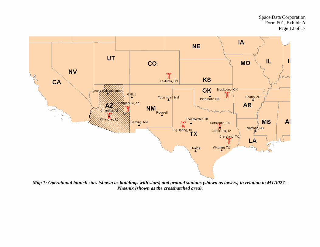
A series of maps are attached to this Exhibit illustrating various aspects of Space Data’s network coverage area, including the smaller Licensed geographic area. Space Data’s launch sites and ground station locations are identified in Map 1. Map 2 depicts the coverage area of individual SkySite® Platforms and the aggregate coverage area of the constellation of SkySite®
Platforms at time T+0:00. Map 3 shows the coverage of the constellation of SkySite® Platforms at two-hour intervals over a 24-hour period, starting at the time when the platforms begin
Space Data Corporation Form 601, Exhibit A
Page 10 of 17
operating at 25,000 meters (70,000 feet). After 24 hours, new SkySite® Platforms are launched and the process repeats. Because the winds move the SkySite® Platforms at an average of 24 kilometers per hour (15 miles per hour) to the west, the SkySite® Platforms coverage area is oval-shaped over the 24-hour period. Map 4 illustrates the geographic area that is covered continually by the SkySite® Platforms and Map 5 includes the areas that have periodic coverage. Map 6 depicts the coverage of the backhaul links from the SkySite® Platforms to Space Data’s six ground stations.
To calculate the Licensed coverage area, the relevant data was entered into a Geographic Information System (GIS) to create coverage contours at the various locations of the SkySite Platforms over the course of their fights, which are shown in Maps 4 and 5. As demonstrated in the maps, Space Data’s network has been constructed to cover continuously 231,203 square kilometers (out of 231,307 square kilometers), or 99.96 percent, of the geographic area of MTA027. The remaining portion of MTA027 receives periodic coverage. Thus, Space Data’s network provides coverage to an area greater than the ten-year 50 percent geographic area coverage requirement set forth in Section 24.103(c) of the Commission’s rules. Accordingly, Space Data certifies that its network satisfies the Commission’s ten-year NPCS license construction requirement for each License.
III. GRANT OF SPACE DATA’S CONSTRUCTION SHOWING SERVES THE PUBLIC INTEREST.
As demonstrated above, each License is constructed to cover continuously almost 100 percent of the Licensed market area. Furthermore, Space Data uses its specialized and technologically sophisticated network to provide vital narrowband data communications to niche markets that are typically unserved or underserved. Specifically, Space Data’s services are used to monitor, control and secure production assets (e.g., wells) of the oil and gas industry that are widely-disbursed in the South-Central United States. In the past, the oil and gas industry has relied on Cellular Digital Packet Data (“CDPD”) networks to monitor and control assets in remote areas. The requirement that cellular carriers offer Analog Mobile Phone System service on all towers, however, is scheduled to sunset in less than 12 months in February 2008. As a result, several cellular carriers are phasing out some of their services and intend to discontinue CDPD service as early as this year. Because the use of digital cellular network protocols results in smaller coverage footprints per tower in comparison to CDPD, tens of thousands of wells are losing wireless coverage. Satellite service often is not an adequate substitute for CDPD service because of significant power limitations at these remote sites and the high power equipment needed to use satellite communications. Thus, Space Data’s narrowband data communications may be the only means for oil and gas companies to continue to monitor and control these important resources, as well as help secure pipeline and other critical infrastructure against terrorist threats.
In addition, Space Data’s network also is uniquely positioned to provide service for other industrial, business and consumer applications, such as public safety communications, irrigation control, alarm system monitoring, and personal messaging. Space Data’s network also provides a unique and innovative way to track trucks and other vehicles (including those containing hazardous shipments) throughout remote regions of the United States that have little or no wireless coverage. Such service is critical for businesses that rely on timely deliveries and

Space Data Corporation Form 601, Exhibit A
Page 11 of 17
monitoring of personnel and shipments, especially in the case of shipments of hazardous materials which, if diverted, could threaten homeland security. Space Data also is active in the Commission’s Tribal Land Bidding Credit program and Space Data’s network provides coverage to the Navajo, Hualapai, Fort McDermitt, and Jicarilla Apache tribal nations. Accordingly, it is in the public interest, convenience and necessity to grant this construction showing.
Space Data Corporation Form 601, Exhibit A
Page 12 of 17
Map 1: Operational launch sites (shown as buildings with stars) and ground stations (shown as towers) in relation to MTA027 - Phoenix (shown as the crosshatched area).

Space Data Corporation Form 601, Exhibit A
Page 13 of 17
Map 2: Coverage of individual SkySite® Platforms (thin lines) and the aggregate coverage of the constellation of SkySite® Platforms (thick outline) at one moment in time in a 24 hour period in relation to MTA027 – Phoenix (shown as the crosshatched
area).

Space Data Corporation Form 601, Exhibit A
Page 14 of 17
Map 3: SkySite® Platform constellation coverage area at two-hour intervals over 24 hours of operation at altitude in relation to MTA027 - Phoenix (shown as the crosshatched area).

Space Data Corporation Form 601, Exhibit A
Page 15 of 17
Map 4: Space Data’s network is constructed to provide continuous coverage of the shaded area in relation to MTA027 - Phoenix (shown as the crosshatched area).

Space Data Corporation Form 601, Exhibit A
Page 16 of 17
Map 5: Space Data’s network is constructed to provide continuous or periodic coverage of the shaded area in relation to MTA027 - Phoenix (shown as the crosshatched area).

Space Data Corporation Form 601, Exhibit A
Page 17 of 17
Map 6: The backhaul coverage from each of Space Data’s deployed ground stations provides
adequate coverage of all SkySite® Platforms at altitude over the course of their flights.