JPEmanuscript.jpe.or.kr/LTKPSWeb/uploadfiles/be/201709/... · loads and high power industrial loads...
13
This file is not the final version of this paper. This paper was recently accepted for the publication and it will be published in JPE soon.1 JPE Type-2 Fuzzy Logic Predictive Control of a Grid Connected Wind Power Systems with Integrated Active Power Filter Capabilities Noureddine Hamouda a,b , Hocine Benalla a , Kameleddine Hemsas c , Badreddine Babes b† , Jürgen Petzoldt d , Thomas Ellinger d and Cherif Hamouda e a Laboratory of Electrical Engineering of Constantine (LEC), University of Freres Mentouri, 25000 Constantine, Algeria b Research Center in Industrial Technologies (CRTI) P.O. Box 64, Cheraga16014 Algiers, Algeria c Automatic Laboratory of Sétif, Department of Electrical Engineering, University of Sétif 1, Sétif, 19000 Algeria d Department of Power Electronic and Control, Technische Universität Ilmenau, 98693Ilmenau, Germany e Institut Jean Lamour, UMR 7198, CNRS University of Lorraine, Nancy, France Abstract This paper proposes a real-time implementation of an optimal operation of a double stage grid connected wind power system incorporating an active power filter (APF). The system is used to supply the nonlinear loads with harmonics and reactive power compensation. On the generator side, a new adaptive neuro fuzzy inference system (ANFIS) based maximum power point tracking (MPPT) control is proposed to track the maximum wind power point regardless of wind speed fluctuations. Whereas on the grid side, a modified predictive current control (PCC) algorithm is used to control the APF, and allow to ensure both compensating harmonic currents and injecting the generated power into the grid. Also a type 2 fuzzy logic controller is used to control the DC-link capacitor in order to improve the dynamic response of the APF, and to ensure a well-smoothed DC-Link capacitor voltage. The gained benefits from these proposed control algorithms are the main contribution in this work. The proposed control scheme is implemented on a small-scale wind energy conversion system (WECS) controlled by a dSPACE 1104 card. Experimental results show that the proposed T2FLC maintains the DC-Link capacitor voltage within the limit for injecting the power into the grid. In addition, the PCC of the APF guarantees a flexible settlement of real power exchanges from the WECS to the grid with a high power factor operation. Key words: Active power filter (APF), Adaptive neuro fuzzy inference system (ANFIS), Maximum power point tracking (MPPT), Predictive current control (PCC), Type-2 fuzzy logic controller (T2FLC) I. INTRODUCTION Nowadays, wind energy is one of the most important renewable energy sources (RESs), which can be used not only for standalone systems but also for utility grid systems. Principally, wind generation systems installed near the places where high level of energy are consumed are very appropriate for supplying local loads and help to manage the whole power system needs. When the number of power electronics devices increases in power systems, the quality of the electric energy supplied to consumers tends to deteriorate. Both domestic nonlinear loads and high power industrial loads are sources of the current harmonics distortions and unbalanced currents in electric energy supplies. To overcome these problems, APFs have been rapidly expanding by taking advantages of recent development in power electronics technology. They allow for the compensation of current harmonics, reactive power and current imbalances in power systems. If an individual consumer installs an APF to mitigate current harmonics, the installation cost can be unaffordable [1]. In places with available renewable energy sources, it is useful to use wind energy conversion system (WECS) to supply local loads as well as an APF to compensate the reactive power and current harmonics in the utility grid [2]. As a result, the grid deliver only sinusoidal current at a unity power factor. The resulting system presents a reduced cost without supplementary hardware. Typically, there are two issues to control the proposed system. The first one consists of tracking the maximum power point (MPP) of the wind turbine. Or in this topic the bibliography contains many different algorithms, such as a simplified and advanced perturbation and observation To Be Published
Transcript of JPEmanuscript.jpe.or.kr/LTKPSWeb/uploadfiles/be/201709/... · loads and high power industrial loads...

This file is not the final version of this paper. This paper was recently accepted for the publication and it will be published in JPE soon.1
JPE
Type-2 Fuzzy Logic Predictive Control of a Grid Connected Wind Power Systems with Integrated
Active Power Filter Capabilities
Noureddine Hamouda a,b, Hocine Benalla a, Kameleddine Hemsas c, Badreddine Babes b†, Jürgen Petzoldt d, Thomas Ellinger d and Cherif Hamouda e
aLaboratory of Electrical Engineering of Constantine (LEC), University of Freres Mentouri, 25000 Constantine, Algeria
bResearch Center in Industrial Technologies (CRTI) P.O. Box 64, Cheraga16014 Algiers, Algeria cAutomatic Laboratory of Sétif, Department of Electrical Engineering, University of Sétif 1, Sétif, 19000 Algeria
dDepartment of Power Electronic and Control, Technische Universität Ilmenau, 98693Ilmenau, Germany eInstitut Jean Lamour, UMR 7198, CNRS University of Lorraine, Nancy, France
Abstract
This paper proposes a real-time implementation of an optimal operation of a double stage grid connected wind power system incorporating an active power filter (APF). The system is used to supply the nonlinear loads with harmonics and reactive power compensation. On the generator side, a new adaptive neuro fuzzy inference system (ANFIS) based maximum power point tracking (MPPT) control is proposed to track the maximum wind power point regardless of wind speed fluctuations. Whereas on the grid side, a modified predictive current control (PCC) algorithm is used to control the APF, and allow to ensure both compensating harmonic currents and injecting the generated power into the grid. Also a type 2 fuzzy logic controller is used to control the DC-link capacitor in order to improve the dynamic response of the APF, and to ensure a well-smoothed DC-Link capacitor voltage. The gained benefits from these proposed control algorithms are the main contribution in this work. The proposed control scheme is implemented on a small-scale wind energy conversion system (WECS) controlled by a dSPACE 1104 card. Experimental results show that the proposed T2FLC maintains the DC-Link capacitor voltage within the limit for injecting the power into the grid. In addition, the PCC of the APF guarantees a flexible settlement of real power exchanges from the WECS to the grid with a high power factor operation. Key words: Active power filter (APF), Adaptive neuro fuzzy inference system (ANFIS), Maximum power point tracking (MPPT), Predictive current control (PCC), Type-2 fuzzy logic controller (T2FLC)
I. INTRODUCTION
Nowadays, wind energy is one of the most important renewable energy sources (RESs), which can be used not only for standalone systems but also for utility grid systems. Principally, wind generation systems installed near the places where high level of energy are consumed are very appropriate for supplying local loads and help to manage the whole power system needs.
When the number of power electronics devices increases in power systems, the quality of the electric energy supplied to consumers tends to deteriorate. Both domestic nonlinear loads and high power industrial loads are sources of the current harmonics distortions and unbalanced currents in electric energy supplies. To overcome these problems, APFs have been rapidly expanding by taking advantages of recent
development in power electronics technology. They allow for the compensation of current harmonics, reactive power and current imbalances in power systems.
If an individual consumer installs an APF to mitigate current harmonics, the installation cost can be unaffordable [1]. In places with available renewable energy sources, it is useful to use wind energy conversion system (WECS) to supply local loads as well as an APF to compensate the reactive power and current harmonics in the utility grid [2]. As a result, the grid deliver only sinusoidal current at a unity power factor. The resulting system presents a reduced cost without supplementary hardware.
Typically, there are two issues to control the proposed system. The first one consists of tracking the maximum power point (MPP) of the wind turbine. Or in this topic the bibliography contains many different algorithms, such as a simplified and advanced perturbation and observation
To Be Published

algorithm [3], an adaptive MPPT compensation algorithm [4], a two-stage control method [5], a hill-climb searching control method [6], and others [7-11].
The second issue consists of the development of an efficient predictive current control (PCC) design for active power filtering systems. In order to calculate a justified reference current for such a system, the modified PCC algorithm is used [12]. The main advantages of this control algorithm are its high convergence speed, robustness with respect to load power variations and internal parameters variations, and less sensitivity to noise in measurements when compared to other available techniques.
On the other hand, a type-2 fuzzy logic controller (F2LCs) is used to guarantee a smooth DC-Link capacitor voltage in the APF system, and to improve the dynamic response of the APF. The choice of a T2FLC over type-1 fuzzy logic controllers (F1LCs) is due to the fact that it deals better with uncertainties conditions, has a good processing that can handle the non-linearity in large time delays and may be more robust [13].
In this scope, the present work describes how an operation of a small scale wind generation system connected to the utility grid, and nonlinear load can be achieved. The main objectives assigned to the proposed system are:
1. Ensure permanent transmission of the maximum power from the wind turbine by optimal tuning of the boost converter duty ratio using an ANFS based P&O-MPPT method.
2. Meet the total real power demanded by the local nonlinear loads.
3. Compensate the reactive power and harmonic components of the load current at the point of common coupling.
4. A total flow of the generated wind power to the utility via the PCC of the APF.
5. Improve the dynamic response of the APF and ensures a smooth DC-Link capacitor voltage via an IT2FLC.
II. CONFIGURATION OF THE WIND POWER SYSTEM BASED ON AN APF
Fig. 1 shows the general power circuit configuration of the proposed APF fed by a wind power system. The system is realized using a permanent magnet synchronous generator (PMSG) driven by a variable speed wind turbine, an AC/DC three phase rectifier connected at the front end of the PMSG, a DC/Dc boost converter and a DC-Link capacitor connected in series with a three-phase voltage source inverter (VSI), which is coupled at the point of common coupling with a nonlinear load and the AC grid. The power flow is always from the wind power system to the AC grid and no batteries are required.
Fig. 1. Overall circuit configuration of an APF fed by a WECS.
III. DESIGN PROCEDURE OF THE POWER CIRCUIT
OF THE PROPOSED APF In this section, the design concept of the proposed APF is
studied in detail. In particular, the determination of the DC-Link capacitor voltage (Vdc), the design of the DC-Link capacitor (Cdc), and the coupling inductor (Lf) of the APF are presented.
A. Design of the DC-Link Capacitor Voltage
Generally, the DC-Link capacitor voltage (Vdc) depends on
the instantaneous energy available to the APF. The DC-Link voltage across the capacitor is chosen to be more than the peak grid voltage to keep track with changes in the load demand, and may be estimated as [15]:
2 2 2 2180 293.93
3 3 1dc f LLV V V
m
(1)
Where Vf-LL is the AC-Line voltage of the APF and its value is 180V, while m is the modulation index, which is considered to be equal to 1. Then, from (1) the estimated value of Vdc is 293.93V, and is selected as 300V.
B. Design of the DC-Link Capacitor
According to the guidelines of the APF given in [16], the DC-Link capacitor (Cdc) depends on the instantaneous energy present in the APF at the time of transients. Thus, the design of the DC-Link capacitor (Cdc) for an APF is calculated as:
2 21
1( ) ( ) 3 ( )
2 dc dc dc f fC V V V h I t (2)
where Vdc is the base voltage of the DC-Link capacitor (Cdc), and its value is considered to be 300V; Vdc-1 is the last voltage level of the DC-Link capacitor, and its value is taken as 295 V;
Vf is the APF phase voltage (Vf=Vf-LL/√3), and its value is
103.92 V; h is the overloading factor, and its value is considered as 1.2; If is the APF phase current (If=P/3Vf), and its value is 11.22 A; and t is time required for the DC-Link capacitor voltage (Vdc) to regain, and its value is considered as 200 μs. Therefore, the value of Cdc from (2) is calculated in the order of 977.55 μF. For practical considerations, a value of 1100 μF was chosen.
To Be Published

C. Design of the Coupling Inductor
The value of the coupling inductor (Lf) between the point of common coupling and the APF depends upon the allowable APF current limit (∆Ip-p), the DC-Link capacitor voltage (Vdc), and the maximum switching frequency (fs) of the VSI. Therefore, the inductor value Lf is given as [17]:
( )
3 3 1 3004.3
12 12 1.2 15000 0.05 11.22dc
fs p p
mVL mH
h f I
(3)
Consider, a peak to peak current ripple of ∆Ip-p=5%, Vdc = 300 V, m = 1, h = 1.2 and fs = 15 kHz. Therefore, the coupling inductor is chosen as 5 mH.
IV. PROPOSED MPPT CONTROL METHOD
Maximum power point tracking (MPPT) is an essential task in WECSs. In order to achieve this task accurately, this process is decomposed into two sub-tasks: (i) maximum power point (MPP) identification based an adaptive neuro fuzzy inference system (ANFIS) estimator to determine the optimal reference current (IMPP) corresponding to the best power point; and (ii) a closed loop PI compensator to bring the operating point of the WECS to the (IMPP) by modifying the duty ratio of the boost converter.
A. Design of an ANFIS for MPP Tracking
The developed ANFIS regulator generates a change in the optimal reference current (∆IMPP), based on the input signal error e(k) and the change in the error signal ∆e(k), which are defined as follows:
( ) ( 1)( )
( ) ( 1)d d
d d
P k P ke k
V k V k
(4)
( ) ( ) ( 1)e k e k e k (5)
where Pd(k), Vd(k), Pd(k-1) and Vd(k-1) indicate the DC-side power and corresponding DC-side voltage at the sampling instants k and k-1, respectively.
These inputs are selected so that the instant value of e(k) is shown if the WECS operation power point is located on the right (e(k)<0) or on the left (e(k)>0) when compared with the actual position Pmax(k). While the input ∆e(k) expresses the moving direction of this operation point. The DC-side power is calculated as:
( ) ( ) ( )d d dP k V k I k (6) where Id(k) and Vd(k) denote the DC-side current and voltage at the sampling instant k, respectively. In this paper, a first order Sugeno type fuzzy inference was employed for the ANFIS and the typical fuzzy rules are given as follows:
_
Rule i : IF ( ) and ( ) ; Then
( ) ( ) ;? , , 25
j j
MPP i i i i
e k is A e k is B
I k r e k s e k t i
(7)
where Aj and Bj(j=1,…,5) are fuzzy sets in the antecedent, while ri, si and ti are the consequent parameter set which is
adjusted during training. The significances of the ANFIS structure are:
Layer 1: Each adaptive node in this layer generates the membership grades for the input variables Aj and Bj, where j =1,..., 5, the node function is a Gaussian membership function and the corresponding node equations are given below:
1, 2
1;
1ij Aj Aj b
i
i
O e k e ke k c
a
(8)
2, 2
1( ) ; ( )
( )1
ij Aj Aj b
i
i
O e k e ke k c
a
(9)
where ai, bi and ci are parameters of the Gaussian membership function.
Layer 2: The total number of rules is 25 in this layer. Each node output represents the activation level of a rule.
2, ( ) ( ) , 1, ,25i i Aj BjO W e k e k i , and j=1… 5 (10)
Layer 3: The fixed node i in this layer calculates the ratio of the ith rules activation level to total of all activation levels:
*3,
1 2 25
, 1, , 25ii i
WO W i
W W W
(11)
Layer 4: The adaptive node i in this layer calculates the contribution of the ith rule towards the overall output, with the following node function:
* *4, _ ( ) ( ) , 1, ,25i i MPP i i i i iO W I W p e k q e k z i (12)
Layer 5: The single fixed node in this layer computes the overall output as the summation of the contributions from each of the rules:
_ 2 2525
1 _1 2 25 _*5, _
1 2 251
,
1, , 25
MPP MPP MPP
i i MP ii
P
W I W I W IO W I
W W W
i
(13)
After that, an initial FIS model is generated. This FIS was trained using the hybrid learning optimization method, which employs the least-squares method and the back propagation gradient descent method. The parameters to be trained are (ri, si and ti) of the premise parameters and (pi, qi and zi) of the consequent parameters. The training algorithm requires a training set defined between the inputs and outputs. In this process, the pair of input/output data sets under different wind speeds is collected using a P&O-MPPT algorithm and they are trained by the ANFIS controller. About 800 sets of obtained data are used to train the ANFIS for the purpose of MPPT. The training is done offline using the fuzzy logic toolbox of MATLAB R2009b. The ANFIS reference model is trained for 2000 epochs. The target error is condensed to approximately 2% and the training waveform is shown in Fig. 2.
To Be Published

Fig. 2. Training error for the ANFIS controller.
Once the optimal reference current (IMPP) is located, the PI controller forces the wind turbine generator to work at the optimal current by comparing the actual inductor current of the DC/DC boost converter with the reference current obtained from the ANFIS regulator by controlling the duty ratio of the boost converter d(k). The duty ratio of the boost converter is tuned through adjusting the IGBT switches. A high carrier frequency pulse width modulator (PWM) block provides the gating signals to the IGBT. The block diagram of the PI-ANFIS based MPPT method is shown in Fig. 3.
Fig.3. Block diagram of a PI-ANFS controller.
V. CONTROLLER DESIGN FOR AN APF
To permit the total flow of the extracted wind power into the grid, the voltage source inverter (VSI) control is performed in a cascade manner through the control of both the DC-Link capacitor voltage and the APF currents, which leads to a unit power factor functioning.
A. Synthesis of Fuzzy Type-2 Controller for DC-Link Voltage Regulation
For a perfect balance of the active power flow between the wind power system, AC grid and a nonlinear load, the DC-Link capacitor voltage (Vdc) should be maintained constantly at its required magnitude regardless of system disturbances. To regulate and maintain Vdc at its reference value, a DC-Link capacitor voltage controller is used. Thus, the DC-Link capacitor voltage controller can be defined based on the following constraint:
gdc wdc
dc dc
PdV PC
dt V V (14)
where Cdc is the DC-Link capacitor, Pw and Pg are the active powers of the wind generator and the grid, respectively. If Pw and Pg are equal, there is no change in Vdc.
,
mw t m g loss
dP P J P
dt
(15)
where ωm is the rotor speed of the wind turbine, Pg,loss is the generator power loss, and Pt is the output mechanical power of the wind turbine. From (14) and (15), a dynamic equation for Vdc is presented in (16) when the dynamic characteristics of the wind turbine are considered.
,dc m
dc dc t m g loss grid
dV dC V P J P P
dt dt
(16)
Equation (16) shows the nonlinear relation between the DC-Link capacitor voltage (Vdc) and the rotor speed of wind turbine (ωm). This system is described by this nonlinear equation and can be controlled using a nonlinear controller. A fuzzy-2 controller (F2C) provides a convenient method for constructing a nonlinear controller via the use of expert knowledge. The membership functions (MFs) of type-2 fuzzy sets (T2FS) are three dimensional, and include a footprint of uncertainty (FOU) with the new third dimension of the T2FS. The T2FS make it possible to directly model systems that have many uncertainties. Therefore, a T2FS that uses interval type-2 (IT2) fuzzy sets is used in this paper to control the DC-Link capacitor voltage and it replaces the traditional PI controller.
B. Basic Interval Type-2 Fuzzy Sets (IT2FS)
The interval type-2 (IT2) fuzzy set (IT2FS) is a particular form of T2FS in which the membership value for every point is a crisp number in the interval of [0 1] instead of a crisp number of either 0 or 1. This means that each membership function is described by two MFs, namely a lower membership function (LMF), and upper membership function (UMF) as indicated in Fig. 4.
Fig. 4. Membership function of an IT2FS.
An IT2 fuzzy set (IT2FS) is selected in this paper because it is more suitable for real-time applications [18]. The structure of an IT2FLSs is similar to that of the conventional T1FLSs structure counterpart except for its involving membership functions (MFs) and a defuzzifier block.
In general, in fuzzy systems with IT2 fuzzy MFs in the antecedents, a crisp input is primarily converted to IT2 fuzzy input sets. These input sets activate each of the rules with an interval of strength. Using a conventional defuzzifier in this
To Be Published

case results in an interval of output values rather than a crisp one. Hence, an additional process called a type reduction should be done to generate a crisp output. Fig. 5 illustrates the block diagram of the T2FLC, which mainly contains five basic elements, i.e., fuzzifer, rule, inference, type reducer and defuzzifier.
Fig. 5. Architecture of T2FLC algorithm.
A Type-2 Mamdani fuzzy logic system, which is exploited in this work is one whose membership functions in the antecedents (IF) are IT2FS ones, and the consequences (THEN) are crisp numbers. Now consider the sth fuzzy rule of a Type-2 Mamdani fuzzy logic system with a crisp input Xi and a crisp output yi(x):
1 1: is and is
is ( ) , 1
i i
i l r
X F X F
y y x y x s M
sR IF Then (17)
where F1,…Fi are the IT2 fuzzy sets of the IF-ingredient, and yl(x) and yr(x) are the singleton left and right control actions of the THEN-ingredient, respectively. The process of input–output mapping can be formulated as follows:
1- Compute the firing intervals (weight intervals) for all of the rules using a product t-norm operator:
쟭? min ax ?i Fi Fi탘 탘w (18)
2- Calculate the interval weighted average output from all of the rules (type reduction) based on the center of sets type reduction:
( )
min ( )i ii
wii
y x wy x
w
(19)
( )
max ( )i iu
wii
y x wy x
w
(20)
3- Calculation of the crisp output (defuzzification) of an interval singleton type-2 FLS based on the arithmetic mean of the two end points of the type-reduced set:
2
i uy yy x
(21)
C. T2FLC for DC-Link Capacitor Voltage Regulation
The design of the T2FLC for DC-Link capacitor voltage regulation is configured in a method that is similar to that of the conventional type-1FLC. The proposed controller is designed with the help of the T2 fuzzy inference system toolbox in MATLAB software. The inputs of the T2FLC include the capacitor voltage deviation (error E), and its derivative (error rate CE), whereas the output (CV) of the
T2FLC is the magnitude of the active current component corresponding to the APF losses.
The Gaussian membership function is chosen for the input and output. The discourse universe of the MFs are -1 to 1 for E(k), -0.1 to 0.1 for CE(k), and 0 to 3 for CV(k) as presented in Fig. 6.
(a)
(b)
(c)
Fig. 6. Membership functions of a T2FLC: (a) input error E(k); (b)
input error rate CE(k); and (c) output CV(k).
Seven membership functions are constructed for each E(k), CE(k), and CV(k). The fuzzy sets labels are defined as ‘NB’=Negative Big, ‘NM’=Negative Medium, ‘NS’=Negative Small, ‘ZE’=zero, ‘PS’=Positive Small, ‘PM’=Positive Medium, and ‘PB’=Positive Big, respectively. The width of the FOU is adjusted by observing its effects on the oscillations of the DC-Link capacitor voltage. The antecedent (IF) – consequence (THEN) form is used to express the fuzzy rule. A total of 49 rule matrix is designed for the optimal performance of the controller which is given in the Table I.
TABLE I FUZZY-2 RULE TABLE
E/CE NB NM NS ZE PS PM PB
NB NB NB NB NB NM NS ZENM NB NB NB NM NS ZE PSNS NB NB NM NS ZE PS PMZE NB NM NS ZE PS PM PBPS NM NS ZE PS PM PB PBPM NS ZE PS PM PB PB PBPB NB NM NS ZE PS PM PB
In this work, a Type-2 Mamdani FLC is selected, and the popular center of the sets method is assigned for the type reduction process. The Karnik-Mendel iterative procedure is
To Be Published

then used to generate the type-reduced set of the proposed T2FLC. The defuzzified output for the interval type-reduced set can be obtained by getting the average of (yi) and (yu), i.e.:
2
i uy yy x
(22)
This is a crisp output, which can be applied to the input of the current loop regulation of the APF.
D. Predictive Current Control (PCC) Algorithm for APF Current Loop Regulation
There are several control techniques for APFs based on time and frequency domain [18-19-20]. In this paper the predictive current control (PCC) is chosen since it allows a quick response and appropriate sinusoidal current tracking capability. In addition, it is very simple and easy to implement because it does not need any complex mathematical model or algorithm [21]. The control system structure described hereafter constitutes a revised improved version of a traditional deadbeat control that was recently proposed for standard applications of the APF based three phase VSI [22].
In this subsection, the synthesis of the PCC strategy for wind power system fed APF along with reference current generation is carried out. To develop this strategy, it is necessary to create a predictive current model of APF. The dynamic model of APF can be obtained from the equivalent single-phase circuit of a three-phase VSI connected at the point of common connection, as shown in Fig. 7.
Fig. 7. Simplified representation of an APF with a single-phase circuit.
The equation describing such simple circuit results is as follows:
( ) ( ) ( )( )f f f
ff f
di t R e t v ti t
dt L L
(23)
where e(t) is the mains phase voltage at the point of common connection, if(t) is the pertinent phase current drawn by the APF, vf(t) is the averaged value of the APF leg voltage, Rf and Lf are the resistance and inductance of the AC filter inductors.
The employed PCC approach is based on the discrete linear model of the equivalent single-phase circuit derived from (23). For the sampling period (Ts) between the time instants k and k+1, assume that the grid voltage and the APF voltage are constant, and define them as E(k) and Vf(k). The discrete linear model of the APF is given by equation (24):
11 . .
sf
sf
TR TL
f f ff
ei k i k e E k V k
R
(24)
Introducing the a and b parameters:
1f
sf
RTL f
sf
Ra e T
L
, and 1 11
sfT
sf s
f f f
RTL Te
bR R L
where the coefficients a and b are approximated by a Taylor series. The time constant of the output stage of the APF is denoted by (τ=Lf/Rf). The APF current at time instants k and k+1 are denoted by if(k) and if(k+1), respectively.
The APF behavior may be then rewritten in an approximated form as:
1 . .f f fi k i k a E k V k b (25)
In order to design two-steps ahead PCC, the discrete APF model for the sample period between the time instances k+1and k+2 can be rewritten from (25) as follows:
2 1 . 1 1 .f f fi k i k a E k V k b (26)
It should be noted that the point of common connection voltage is predicted to exhibit a quite sinusoidal waveform. For its prediction, a simple linear extrapolation algorithm was used according to:
1 2. 1E k E k E k (27)
The aim of this PCC is to calculate for the next sampling period Ts between the time instances k+1 and k+2 such an APF voltage reference Vf =Vi (i=a, b, c) which is the current error at the time instant k+2 is omitted, as represented in Fig. 8.
Fig. 8. Predictive current controller (PCC) principal. For the purposes of controlling the current error at the
sampling period between the time instants k+1 and k+2 can be introduced as:
*2 2 2f f fi k i k i k (28)
Where:
( 2) 0fi k (29) The reference APF average voltage to eliminate the current
error at the time instant k+2, (i.e. to make) can be given from equations (25), (26) and (27) as:
*1( 1) ( 1) .[ ( 2) ( 1). ]f f fV k E k i k i k a
b (30)
To Be Published

Frequently in the application of the APF, the current references consist of the 5th and the 7th harmonics, which makes a prediction of the current reference complex. To avoid this difficulty, a polynomial extrapolation technique is proposed for current reference generation in transient conditions.
Normally, a second-order two-ahead extrapolation method use values from a previous sampling instants can be applied to estimate a value of the current reference at the time instant k+2.
* * * * *0 1 22 . . 1 . 2 . ( )f f f f n fi k a i k a i k a i k a i k n (31)
where ai (i=0 to n) are the polynomial coefficients to be calculated. There are 9 coefficients to be determined if a compensation of the 5th, 7th and 11th harmonics is wanted. These parameters have been chosen using a Genetic Algorithm Optimization (GAO) based on the minimization of the subsequent fitness function:
* ( )f ferror i k i k (32)
where if*(k) denotes a predicted current reference at the time
instant k. The GAO search results are listed in Table II.
TABLE II REFERENCE GENERATION BASED GAO PARAMETERS
h 5th 7th 11th a_h 5.3695 -0.2398 11.4581b_h -7.1420 2.7384 18.2503c_h 2.6985 -2.5251 12.8374
The APF voltages reference values obtained from (30) are forwarded to a Space Vector Modulator (SVM) functioning in asymmetric form, which permits the use of a constant sampling frequency that is twice the VSI switching frequency. The block diagram of the overall control structure considering both the voltage and current control loop is pictured in Fig. 9.
Fig. 9. General control scheme of the APF.
Taking into account the difference between the modeled filter inductance Lf and its real value L, the closed current loop transfer function for the current control loop can be defined
with the next three discrete equations in the z-domain. The first two equations present the behavior of the PCC, while the third equation describes the real plant.
* 2. . 1ff f f
s
LV k z E k i k z i k
T
(33)
1 . . ( )sf f f f
f
Ti k E k V k L i k
L (34)
1 1 * 1. . .ff f f
s
LV k z E k z i k i k z
T
(35)
From equations (33), (34) and (35), taking into account the grid voltage as a disturbance, the closed current loop transfer function is:
2
* 2
.( )
1
ff
f f
L L zi z
i z z L L
(36)
Ignore the parameters mismatch (i.e Lf/L=1) in (36). The closed current loop poles must to be moved from the origin to attain better noise rejection. In order to move the current loop closed loop poles from the origin, a new prediction method for the APF current at the instant k+1 is proposed here:
* *
*
* *
1 1
1 1
1 1 0.5. 0.5.
1
1
f f f f f
f f f
f f f f
i k i k i k i k i
i i k i k
i k i k i k
k
i k
k
(37)
From equations (33), (35) and (37) the transfer function of the closed loop current control is:
2
* 2
. . .0.5( )
0.5.f f ff
f f
L L z L L z L Li z
i z z z L L
(38)
The stability of the closed loop current control is ensured until the input inductance is overestimated by 100%, as shown in Fig. 10.(a-b), confirming a good robustness to parameter inaccuracies. Underestimation of the filter inductance is not critical.
Pole-Zero Map
Real Axis
Imag
inar
y A
xis
-1 -0.5 0 0.5 1-1
-0.8
-0.6
-0.4
-0.2
0
0.2
0.4
0.6
0.8
1
0.1/T
0.2/T
0.3/T
0.4/T0.5/T
0.6/T
0.7/T
0.8/T
0.9/T
/T
0.10.2
0.30.40.50.60.70.80.9
0.1/T
0.2/T
0.3/T
0.4/T0.5/T
0.6/T
0.7/T
0.8/T
0.9/T
/T
-1 -0.5 0 0.5 1-1
-0.8
-0.6
-0.4
-0.2
0
0.2
0.4
0.6
0.8
1
0.1/T
0.2/T
0.3/T
0.4/T0.5/T
0.6/T
0.7/T
0.8/T
0.9/T
/T
0.10.2
0.30.40.50.60.70.80.9
0.1/T
0.2/T
0.3/T
0.4/T0.5/T
0.6/T
0.7/T
0.8/T
0.9/T
/T
Pole-Zero Map
Real Axis
Imag
inar
y A
xis
(a) (b)
Fig.10. Poles-zeros placement for the PCC as Lf varies: a) ideal case; b) stability boundary (100% error in the APF impedance estimation).
VI. EXPERIMENTAL VALIDATION
To Be Published

A. Test Bench Presentation To assess practically the performance of the proposed
control scheme in a real-time environment, an experimental platform is developed in the laboratory. A block diagram of the experimental setup is depicted in Fig. 11.
Fig. 11. Configuration of the experimental platform.
The hardware part of the system mainly consists of the following equipment: (a) a small rating PMSG coupled with a DC-shunt motor, to simulate wind turbine characteristics, and an uncontrolled rectifier; (b) a DC/DC boost converter; (c) a three-phase VSI based APF connected to the same node of the grid and nonlinear load; (d) two real-time dSPACE1104 cards from Texas Instrument with a TMS320F240 DSP (20 MHz) used to implement the converters control algorithms. These algorithms include the ANFIS based P&O-MPPT control, the T2FLC and the APF predictive current control (PCC); (e) a power quality analyzer and a four channel digital storage oscilloscope are used to record the experimental data.
A general view of the experimental test bench built for the implementation of the proposed control methods is shown in Fig.12. The technical data of the test bench are listed in Table III.
Fig.12. Prototype of a WECS with an APF: 1) dSPACE I/O connectors; 2) control desk panel; 3) PMSG; 4) shunt-DC motor; 5) APF; 6) nonlinear load; 7) grid; 8) speed sensor; 9) power analyzer; 10) voltage sensor; 11) current sensor; 12) boost filter inductance.
TABLE III
SYSTEM PARAMETERS
Parameter Value Units
Rated output power of PMSG (PN) Rated torque (TN) PMSG stator resistance (Rs ) PMSG stator inductance (Ls)
Permanent magnet flux () Pole pairs (P) Torque constant (kT) Boost inductance (Ld) DC-Link capacitance (Cdc) Filter inductance (Lf) Switching frequency (fs) Grid frequency (f) Grid voltage (Vg)
3.5 22.5 0.65
8 0.39
4 2.39 10
1100 5 15 50 180
Kw Nm
mH Wb
- Nm/A mH μF mH kHz Hz V
B. Results and Discussion
To test the effectiveness of the proposed PCC algorithm, the type 2 fuzzy logic control and the research algorithm of MPP tracking, various wind speeds and nonlinear loading conditions to sweep all of the modes of operation of our system are carried out. The following observations are made on these test results under steady-state and dynamic conditions.
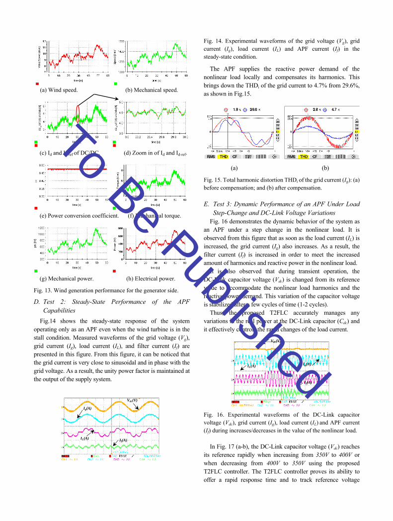
C. Test 1: Maximum Real Power Generation by the ANFIS Controller Based MPPT Method
In this test, the goal of the algorithm is to track the maximum power operating point of the system. Fig.13 shows several experimental results obtained using the Control-Desk software. The presented graphs correspond to: the wind speed, the turbine shaft speed, the DC-side current of the boost converter (Id) and its optimal reference (IMPP), the power conversion coefficient Cp, the mechanical torque, the power captured from the wind (mechanical power), and the power provided to the grid (electrical power).
As can be seen from the plots in Fig.13, the turbine shaft speed is continuously matched to the wind speed in such a way that it extracts the maximum power out of the wind. The DC-side current (Id) is controlled according to the MPPT strategy and can be better regulated to achieve the optimum reference current (IMPP). In addition, the power conversion coefficient Cp is kept constant, and varies in a relatively small range around its optimal value of 0.47.
The mechanical torque changes to accommodate variations in the wind speed, and the mechanical input power is slightly greater than the produced electrical power due to system losses. The obtained results confirm that the ANFIS controller of the boost converter works properly and is able to generate the maximum wind power according to an increase/decrease in the wind speed.
To Be Published
(a) Wind speed. (b) Mechanical speed.
(c) Id and Id-ref of DC/DC. (d) Zoom in of Id and Id-ref.
(e) Power conversion coefficient. (f) Mechanical torque.
(g) Mechanical power. (h) Electrical power.
Fig. 13. Wind generation performance for the generator side.
D. Test 2: Steady-State Performance of the APF Capabilities
Fig.14 shows the steady-state response of the system operating only as an APF even when the wind turbine is in the stall condition. Measured waveforms of the grid voltage (Vg), grid current (Ig), load current (IL), and filter current (If) are presented in this figure. From this figure, it can be noticed that the grid current is very close to sinusoidal and in phase with the grid voltage. As a result, the unity power factor is maintained at the output of the supply system.
Fig. 14. Experimental waveforms of the grid voltage (Vg), grid current (Ig), load current (IL) and APF current (If) in the steady-state condition.
The APF supplies the reactive power demand of the nonlinear load locally and compensates its harmonics. This brings down the THDi of the grid current to 4.7% from 29.6%, as shown in Fig.15.
(a) (b)
Fig. 15. Total harmonic distortion THDi of the grid current (Ig): (a) before compensation; and (b) after compensation.
E. Test 3: Dynamic Performance of an APF Under Load Step-Change and DC-Link Voltage Variations
Fig. 16 demonstrates the dynamic behavior of the system as an APF under a step change in the nonlinear load. It is observed from this figure that as soon as the load current (IL) is increased, the grid current (Ig) also increases. As a result, the filter current (If) is increased in order to meet the increased amount of harmonics and reactive power in the nonlinear load.
It is also observed that during transient operation, the DC-Link capacitor voltage (Vdc) is changed from its reference value to accommodate the nonlinear load harmonics and the reactive power demand. This variation of the capacitor voltage is stabilized after a few cycles of time (1-2 cycles).
Thus, the proposed T2FLC accurately manages any variations in the real power at the DC-Link capacitor (Cdc) and it effectively controls the rapid changes of the load current.
Fig. 16. Experimental waveforms of the DC-Link capacitor voltage (Vdc), grid current (Ig), load current (IL) and APF current (If) during increases/decreases in the value of the nonlinear load.
In Fig. 17 (a-b), the DC-Link capacitor voltage (Vdc) reaches its reference rapidly when increasing from 350V to 400V or when decreasing from 400V to 350V using the proposed T2FLC controller. The T2FLC controller proves its ability to offer a rapid response time and to track reference voltage
IL(A) Ig(A)
If(A)
Vdc(V)
Ig(A)
If(A)
Vdc(V)
IL(A)
To Be Published

variations, which is a real case of connecting renewable energy to the DC-Link capacitor of the APF without the need for complex equipment.
Fig. 17. Measured waveforms of the DC-Link capacitor voltage (Vdc), grid current (Ig), load current (IL) and APF current (If) during increases/decreases in the value of the DC-Link capacitor voltage.
F. Test 4: Proposed System Performance with the APF and Power Supply
The proposed system was tested by evaluating its capability to follow the variations of the generated power caused by wind speed fluctuations. Fig. 18 shows three situations provided by different states of wind speed.
1. Situation 1: The total load power demand is higher than the generated power (PL>PW) From Fig. 18.a, it is clearly observed that the load current (IL) has a non-sinusoidal waveform, and the grid current (Ig) becomes sinusoidal and in phase with the grid voltage (Vg). Consequently, the VSI plays the role of an active power filter (APF), and the grid must fulfill the rest of active power needs by the local load.
2. Situation 2: The total load power demand is equal to the generated power (PL=PW) In this case, the generated power satisfies the load requirement without the need for grid current (Ig=0A) as shown in Fig. 18.b.
3. Situation 3: The total load power demand is less than the generated power (PL<PW) It can be noticed from Fig. 18.c that the grid current (Ig) has an opposite phase when compared with that of the grid voltage (Vg). It also has a sinusoidal waveform, which leads to a unity power factor. However, a part of the generated power feeds the nonlinear load and the surplus power is injected into the grid.
(c) Fig. 18. Experimental waveforms of the grid voltage (Vg), grid current (Ig), load current (IL), and APF current (If) in the dynamic state conditions: (a) first situation; (b) second situation; and (c) third situation.
G. Test 5: Dynamic Performance of The Proposed System Under Nonlinear Load Variations
To test the robustness of proposed configuration in severe conditions, the nonlinear load was changed by 50% around its nominal value. From Fig. 19.a, we observed that before increasing the nonlinear load, the VSI feeds the load without support from the grid current (Ig=0). By increasing the load, an
extra current is delivered from the grid (Ig≠0) to satisfy the
load current requirements. By returning to the initial load value, the grid current become zero (Ig=0), without any perturbation at the instants of changing the load, which confirms the capability of the proposed PCC to accurately achieve its reference current. Fig. 19.b shows that the DC-Link capacitor voltage (Vdc) is maintained at a constant level of 300 V thanks to the T2FLC, which facilitates the active power flow.
(a) (b) Fig. 19. Dynamic performance under nonlinear load variations.
H. Test 6: Dynamic Performance of the Proposed System Under Wind Speed Variations
From Fig.20.a, it can be observed that the proposed configuration presents good dynamic performances, where this is justified by maintaining a constant value of the DC-link voltage under wind speed variations. In addition, when the wind speed increases, the RMS grid current (Ig) decrease, because the wind turbine provides active power to the nonlinear load. However, when the available power of the wind turbine (Pw) is more than the nonlinear load power, the surplus VSI currents are injected into the grid. As a result, the RMS injection of currents into the grid increases. On the other hand, it is observed from Fig.20.b, that the DC-Link capacitor voltage (Vdc) is regulated to its reference value by
(a) (b)
(a) (b)
Vdc(V) Ig(A)
IL(A)
If(A)
Vg(V) Ig(A)
IL(A)
If(A)
IL(A)
Ig(A)
If(A)
Vdc(V) Ig(A)
If(A)
Vdc(V)
IL(A)
Ig(A)
If(A)
Vg(V)
IL(A)
Ig(A)
If(A)
Vg(V)
IL(A)
Ig(A) Vg(V)
IL(A)
If(A)
To Be Published
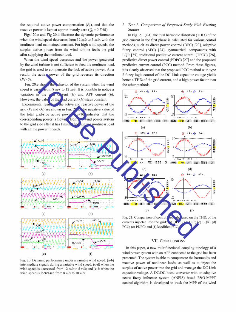
the required active power compensation (Pg), and that the reactive power is kept at approximately zero (Qg =0 VAR).
Figs. 20.c and Fig 20.d illustrate the dynamic performance when the wind speed decreases from 12 m/s to 5 m/s, with the nonlinear load maintained constant. For high wind speeds, the surplus active power from the wind turbine feeds the grid after supplying the nonlinear load.
When the wind speed decreases and the power generated by the wind turbine is not sufficient to feed the nonlinear load, the grid is used to compensate the lack of active power. As a result, the active power of the grid reverses its direction (Pg>0).
Fig. 20.e shows the behavior of the system when the wind speed is varied from 8 m/s to 12 m/s. It is possible to notice a variation in the grid current (Ig) and APF current (If). However, the value of the load current (IL) stays constant. Experimental results of the active and reactive power of the grid (Pg and Qg) are shown in Fig. 20.f. The negative value of the total grid-side active power (Pg<0) indicates that the corresponding power is flowing from the wind power system to the grid side after it has finished feeding the nonlinear load with all the power it needs.
(a) (b)
(c) (d)
(e) (f) Fig. 20. Dynamic performance under a variable wind speed: (a-b) intermediate signals during a variable wind speed; (c-d) when the wind speed is decreased from 12 m/s to 5 m/s; and (e-f) when the wind speed is increased from 8 m/s to 10 m/s.
I. Test 7: Comparison of Proposed Study With Existing Studies
In Fig. 21. (a-f), the total harmonic distortion (THDi) of the grid current in the first phase is calculated for various control methods, such as direct power control (DPC) [23], adaptive fuzzy control (AFC) [24], symmetrical components with LQR [25], traditional predictive current control (TPCC) [26], predictive direct power control (PDPC) [27] and the proposed predictive current control (PCC) method. From these figures, it is clearly observed that the proposed PCC method with type 2 fuzzy logic control of the DC-Link capacitor voltage yields better a THDi of the grid current, and a high power factor than the other methods.
(a) (b)
(c) (d)
(e) (f)
Fig. 21. Comparison of control methods based on the THDi of the currents injected into the grid: (a) DPC; (b) AFC; (c) LQR; (d) PCC; (e) PDPC; and (f) Modified PCC.
VII. CONCLUSIONS
In this paper, a new multifunctional coupling topology of a wind power system with an APF connected to the grid has been presented. The system is able to compensate the harmonics and reactive power of nonlinear loads, as well as to inject the surplus of active power into the grid and manage the DC-Link capacitor voltage. A DC/DC boost converter with an adaptive neuro fuzzy inference system (ANFIS) based P&O-MPPT control algorithm is developed to track the MPP of the wind
Vg(V) Ig(A)
Qg(VAR)
Pg(W)
Ig(A)
Pg(W)
Qg(VAR)
Vdc(V)
Vdc(V)
Ig(A)
If(A)
IL(A)
Vg(V) Ig(A)
Qg(VAR) Pg(W) IL(A) If(A)
Vg(V)
Ig(A)
Vg(V)
Ig(A)
If(A) IL(A)
To Be Published

turbine. The model predictive current control (PCC) algorithm is designed to control the three phase VSI. The use of T2FLC in the control of the DC-Link capacitor voltage makes it more robust and less susceptible to transients of the system. The proposed control scheme is validated through an experiment on a 3.5 Kw PMSG based wind power system connected to the grid via an APF. The obtained results are satisfactory and promising in terms of mitigating current variations and wind power management capability.
REFERENCES
[1] P. Jintakosonwit, H. Fujita, and H. Akagi, “Control and performance of a fully digital controlled shunt active filter for installation on a power distribution system,” IEEE Trans.Power Electron., Vol. 17, No.1, pp. 132-140, Jan. 2002.
[2] M.F. Schonardie, D.C. Martins, “Application of the dqo transformation in the three-phase grid-connected PV systems with active and reactive power control,” ICSET08. IEEE Int. Conf, pp. 18-23, Nov. 2008.
[3] Y. Xia, H. Ahmed K, W. Williams B. “A new maximum power point tracking technique for permanent magnet synchronous generator based wind energy conversion system,” IEEE Trans. Power. Electron, Vol.26, No.12, pp.3609-3620, Dec. 2011.
[4] CT. Pan, YL. Juan. “A novel sensorless MPPT controller for a high efficiency micro-scale wind power generation system,” IEEE Trans. Energy. Convers, Vol. 25, No.1, pp.207-216, Mar. 2010.
[5] V. Agarwal, K. Rakesh, A. Pravin, PC. Patki. “A novel scheme for rapid tracking of maximum power point in wind energy generation systems,” IEEE Trans. Energy. Convers, Vol.25, No.1, pp.228-236, Mar. 2010.
[6] WM. Lin, CM. Hong. “Intelligent approach to maximum power point tracking control strategy for variable speed wind turbine generation system,” Energy, Vol. 35, No. 6, pp. 2440-2447, Apr. 2010.
[7] SM. Raza Kazmi, H. Goto, HJ. Guo, O. Ichinokura. “A novel algorithm for fast and efficient speed sensorless maximum power point tracking in wind energy conversion systems,” IEEE Trans. Ind. Electron, Vol. 58, No. 1, pp.29-36, Jan. 2011
[8] V. Galdi, A. Piccolo, P. Siano. “Designing an adaptive fuzzy controller for maximum wind energy extraction,” IEEE Trans. Energy. Convers, Vol. 23, No. 2, pp.559-569, Jun. 2008.
[9] M. Pucci, M. Cirrincione. “Neural MPPT control of wind generators with induction machines without speed sensors,” IEEE Trans. Ind. Electron, Vol.58, No. 1, pp.37-47, Jan. 2011.
[10] C. Wei, Z. Zhang, W. Qiao, L. Qu, “Reinforcement- learning-based intelligent maximum power point tracking control for wind energy conversion systems”, IEEE Trans Ind Electron 2015, Vol. 62, No. 10, pp.6360-6370, Oct. 2015.
[11] R. Cardenas, R. Pena. “Sensorless vector control of induction machines for variable speed wind energy applications,” IEEE Trans. Convers. Energy, Vol. 19, No.1, pp.196-205, Mar. 2004.
[12] R.S. Herrera, P. Salmeron, “Instantaneous reactive power theory: A comparative evaluation of different formulations,” IEEE Trans. Power Delivery, Vol. 22, No.1, pp. 595-604, Jan. 2007.
[13] K. Abbas, N. Saeid, C. Doug, S. Dipti “Interval Type-2 Fuzzy Logic Systems for Load Forecasting: A Comparative Study” IEEE Transactions on Power System, Vol. 27, No. 3, pp. 1274-1282, Aug. 2012.
[14] B. Singh, D.T. Shahani, A.K. Verma, “Neural network controlled grid interfaced solar photovoltaic power generation,” IET Power Electron, Vol. 7, No. 3, pp. 614-626, Mar. 2014.
[15] B.N. Singh, P. Rastgoufard, B. Singh, A. Chandra, K.A. Haddad, “Design, simulation and implementation of three pole/four pole topologies for active filters,” Proc. IEE Electr. Power Appl., Vol. 151, No. 4, pp. 467-476, 2004.
[16] N.K. Swami Naidu and B. Singh. “Doubly fed induction generator for wind energy conversion systems with integrated active filter capabilities,” IEEE Trans. Ind. Informatics., Vol. 11, No. 4, pp.923-933, Aug. 2015.
[17] D. Wu Woei Wan Tan “A simplified type-2 fuzzy logic controller for real-time control,” ISA Transactions, Vol. 45, No. 4, pp. 503-516, Oct. 2006.
[18] H. Akagi, “Control strategy and site selection of a shunt active filter for damping of harmonic propagation in power distribution systems,” IEEE Transaction. Power Deliv, Vol. 12, No. 1, pp. 354-362, Jan. 1997.
[19] M. El-Habrouk, M. K. Darwish, P. Mehta, “Active power filters A review,” Proc. Inst. Elect. Eng., Vol. 147, No. 5, pp. 403–413, Sept. 2000.
[20] B. Boukezata, J. Gaubert, A. Chaoui, M. Hachemi “Predictive current control in multifunctional grid connected inverter interfaced by PV system” Solar Energy, Vol. 139, pp. 130-141, 2016.
[21] B. Babes, L. Rahmani, A. Chaoui, N. Hamouda, “Design and experimental validation of a digital predictive controller for variable speed wind turbine systems,” Journal of Power Electronics, Vol. 17, No. 1, pp. 232-241, 2017.
[22] M. Odavic, P. Zanchetta, M. Sumner, Z. Jakopovict, “High performance predictive current control for active shunt filters,” EPE-PEMC 2006, pp. 1677-1681.
[23] A. Beddar, H. Bouzekri, B. Babes, H. Afghoul, “Experimental enhancement of fuzzy fractional order PI+I controller of grid connected variable speed wind energy conversion system,” Energy Conversion and Management, Vol. 123 pp. 569-580, 2016.
[24] J. Fei, S. Hou, “Adaptive fuzzy control with supervisory compensator for three-phase active power filter,” Journal of Applied Mathematics, Vol. 2012, Article ID 654937, 13 pages, 2012. doi:10.1155/2012/654937.
[25] B. Kedjar, K. Al-Haddad, “LQR with integral action to enhance dynamic performance of three-phase three-wire shunt active filter,” in proc. of IEE Power Electronics Specialists Conference (PESC), USA, 2007, pp. 1138-1144.
[26] S.G Jeong, M.H Woo. “DSP-Based Active Power Filter with Predictive Current Control,” IEEE Trans. Ind. Electron, Vol. 44, No. 3, pp. 329-336, June 1997.
[27] O. Aissa, M. Moulahoum, I. Colak, B. Babes, N. Kabache, “Analysis, design and real-time implementation of shunt active power filter for power quality improvement based on predictive direct power control,” ICRERA 2016. IEEE Int. Conf, pp. 79-84, 20-23 Nov. 2016.
To Be Published

Noureddine Hamouda received his Electrical Engineering degree from the University of Jijel, Algeria in 2006. He received and his M.S. degree from the University of Setif, Setif, Algeria, in 2010. He is currently working on towards his Ph.D. degree in Electrical Engineering from University of Frères Mentouri Constantine, Constantine, Algeria. Since 2013, he has been with the Research Center in Industrial Technologies (CRTI), Algiers, Algeria. His current research interests include the systems applied to motor drives, active power filters, renewable energy systems and welding techniques.
Hocine Benalla received his DEA and Doctor Engineer degrees in Power Electronics from the National Polytechnic Institute of Toulouse, France in 1981 and 1984, respectively. In
1995, he received his Ph.D in Electrical Engineering from University of Jussieu-Paris 6, France. Since 2006, he has been currently a Professor at University of Frères Mentouri Constantine, Constantine, Algeria . His current research interests include electric machines, ac drives and active filters.
Kamel Eddine Hemsas received his Ingénieur d’état, Magistèr and Docteur d’état with distinction from Ferhat Abbas University, Sétif, Algeria in 1991, 1995 and 2005, respectively. Since 1998, he has been with the Department of Electrical Engineering of Ferhat Abbas
University, where he is presently working as a Professor of multivariable control, diagnosis theory and power quality. His current research interests include phenomena electrical machine modelling, electrical drives, power quality issues, the intelligent control of induction motors, diagnosis, state estimation, and parameter identification.
Badreddine Babes was born in El-Eulma, Algeria, in 1980. He received his degrees in Electrical Engineering from Ferhat Abbas University, Sétif, Algeria, in 2004 and 2010, respectively, where he is currently working towards his Ph.D. degree in Electrical Engineering. Since 2017, he has been with the
Research Center in Industrial Technologies (CRTI), Algiers, Algeria. His current research interests include the predictive control of linear and nonlinear systems applied to motor drives and renewable energy systems. Jürgen Petzoldt (M’01–SM’02) was born in Lepzig, Germany. He received the Diploma and Dr. Ing. degrees in Electrical Engineering from the Department of Power Electronics and Control,, Ilmenau, Germany, in 1976 and 1980, respectively. In 1991, he passed his Habilitation at Technische Universität Ilmenau. From 1979 to 1995, he was with the Department of Power Electronics and Control, Technische Universität Ilmenau. From 1995 to 2000, he was a Professor in the Department of Power Electronics, Universität Rostock, Rostock, Germany. Since 2000, he has been a Professor in the Department of Power Electronics and Control, Technische Universität Ilmenau. He was one of the founders of the Thüringer Leistungselektronik
Union GmbH, Ilmenau, and Isle Steuerungstechnik und Leistungselektronik GmbH, Ilmenau, which are engaged in system development for power electronics, electrical drivers, and energy control. He has authored or coauthored over 70 papers and several books on power electronics and energy control, and he is a holder of 15 patents in these areas. He was the Vice President of the IEEE Power Electronics Society/Industry Applications Society joint German chapter from 2003 to 2004. Thomas Ellinger received the Diploma degree from Fachhochschule Schmalkalden, Schmalkalden, Germany, in 1995 and the Dr. Ing. degree in electrical engineering from the Department of Power Electronics and Control, Technische Universität Ilmenau, Ilmenau, Germany, in 2004. In 2013, he passed his Habilitation at the Technische Universität Ilmenau. From 1997 to 1998, he was with the Basic Engineering Department, Siemens AG, Erlangen, Germany, where he was engaged in the development of superconductive magnetic energy storage. From 2001 to 2003, he was with Isle Steuertechnik GmbH, Ilmenau, as a Research and Development Engineer. Since 2004, he has been with the Department of Power Electronics and Control, Technische Universität Ilmenau. He has authored or coauthored 19 papers and one book on power electronics and energy control. He is the holder of several patents in these areas.
Cherif Hamouda was born in Jijel, Algeria, on August 28, 1984. He received his B.S. degree in Engineering from
the National Polytechnic School, Algiers, Algeria, in 2007; and his M.S. degree in High Frequency Communication Systems and his
Ph.D. degree in the field of High Frequency Electronics from the University of Marne-La-Vallée, Marne-la-Vallée, France, in 2011 and 2014, respectively. From 2015 to 2017, he was a Research Associate in Biomedical Electronics in the Department of Nanomaterials, Electronics and Life (N2EV) of the University of Lorraine, Nancy, France.
To Be Published