STEAM · · 2017-05-13Refineries and chemical plants use steam tracing to reduce pumping costs of...
56
Steam is used throughout industry for process and space heating. Within the process industries, steam is used in oil refineries; pulp and paper mills; chemical production, such as ethylene and ammonia; food and grain processing; and textiles. Refineries and chemical plants use steam tracing to reduce pumping costs of viscous material and prevent freezing of process piping. Steam is used for heat exchangers and reactors to assist or create process chemical or thermal reactions. Paper mills utilize major steam generation systems to generate power and dry paper products. Steam is widely used for district energy systems found in major municipalities and central plants of universities and hospitals. To minimize piping cost, steam is generated and distributed at much higher pressures and temperatures than are required by the process load. Fisher ® regulators are utilized in these applications to reduce the steam pressure to a usable level and to accurately maintain process fluid temperatures. STEAM
-
Upload
hoangtuyen -
Category
Documents
-
view
213 -
download
0
Transcript of STEAM · · 2017-05-13Refineries and chemical plants use steam tracing to reduce pumping costs of...

Steam is used throughout industry for process and space heating. Within the process industries, steam is used in oil refineries; pulp and paper mills; chemical production, such as ethylene and ammonia; food and grain processing; and textiles.
Refineries and chemical plants use steam tracing to reduce pumping costs of viscous material and prevent freezing of process piping. Steam is used for heat exchangers and reactors to assist or create process chemical or thermal reactions. Paper mills utilize major steam generation systems to generate power and dry paper products. Steam is widely used for district energy systems found in major municipalities and central plants of universities and hospitals.
To minimize piping cost, steam is generated and distributed at much higher pressures and temperatures than are required by the process load. Fisher® regulators are utilized in these applications to reduce the steam pressure to a usable level and to accurately maintain process fluid temperatures.
STEAM

106
Kettle
Chiller
Boiler
ProductStorageTanks
Hot WaterTank
HeatExchanger
DA Tank
For:
ZM GRAPHICS • 214-906-4162 • [email protected](c) 2007, ZM Graphics Usage: Unlimited within Emerson & Fisher
File name:
Placed file(s):
For page:
Updated by:
GCG, 817-332-4600
Last updated:
Fisher Tank / Emerson
Production notes:
2007 FISHER-Steam.eps
92B
Carol Zuber-Mallison
92S
92C
92H
08/08/2007
95HPage 139
92SPage132
95HPage 139
92BPage115
92BPage115
92BPage115
92C
Page 122
IntroductionAll Fisher® brand self-powered steam valves are designed for maximum performance and reliability that is required of today’s modern steam systems.
Information in this Application Guide is intended to give you the knowledge and flexibility necessary to apply our steam products correctly, which increases your steam system’s efficiency.
When installed and applied correctly, Fisher brand steam products pay for themselves many times throughout the life of your steam system. In fact, our products may even outlast your boiler.
Emerson’s Fisher brand steam regulators have no equal. Contact your local Sales Office with your steam application questions. We offer solutions that will help you manage your steam systems.
Application: Steam SolutionsFeatures
• Reliable,LongServiceLife • AccuratePressureControl • OverpressureProtection • LowMaintenance • SuperiorDesign • PressureLoadedRegulators • NoiseReduction • RuggedConstruction • HighTurndown

107
Kettle
Chiller
Boiler
ProductStorageTanks
Hot WaterTank
HeatExchanger
DA Tank
For:
ZM GRAPHICS • 214-906-4162 • [email protected](c) 2007, ZM Graphics Usage: Unlimited within Emerson & Fisher
File name:
Placed file(s):
For page:
Updated by:
GCG, 817-332-4600
Last updated:
Fisher Tank / Emerson
Production notes:
2007 FISHER-Steam.eps
92B
Carol Zuber-Mallison
92S
92C
92H
08/08/2007
95HPage 139
92SPage132
95HPage 139
92BPage115
92BPage115
92BPage115
92C
Page 122
Steam application map

108
PRESSUREREdUcIng
REgUlatoRS
MaxIMUM InlEt PRESSURE and tEMPERatURE
oUtlEt PRESSURE RangE
MaxIMUMFloW
tYPE nUMBER
2 to 250 psig (0,14 to 17,2 bar)
2 to 30 psig (0,14 to 2,1 bar)
2 to 250 psig (0,14 to 17,2 bar)
5 to 250 psig (0,34 to 17,2 bar)
5 to 150 psig (0,34 to 10,3 bar)
2 to 250 psig (0,14 to 17,2 bar)
15 to 300 psig (1,0 to 20,7 bar)
42 400 lbs/hr (19 233 kg/hr)
1000 lbs/hr (454 kg/hr)
42 400 lbs/hr (19 233 kg/hr)
3600 lbs/hr (1633 kg/hr)
7500 lbs/hr (3402 kg/hr)
45 100 lbs/hr (20 457 kg/hr)
9100 lbs/hr (4128 kg/hr)
300 psig (20,7 bar) 600°F (316°C)
300 psig (20,7 bar)450°F (232°C)
300 psig (20,7 bar) 600°F (316°C)
300 psig (20,7 bar) 650°F (343°C)
300 psig (20,7 bar)450°F (232°C)
300 psig (20,7 bar)650°F (343°C)
600 psig (41,4 bar)650°F (343°C)
type 92B
Page 115
95l Series
Page 146
type 92P
Page 127
type 92c
Page 122
95H Series
Page 139
type 92S
Page 132
type 95Ht
Page 139
Steam Quick Selection Guide

109
PRESSUREloadEd
contRol ValVES
MaxIMUM InlEtPRESSURE andtEMPERatURE
oUtlEt PRESSURE RangE
MaxIMUMFloW
tYPE nUMBER
2 to 250 psig (0,14 to 17,2 bar)
5 to 250 psig (0,34 to 17,2 bar)
42 400 lbs/hr (19 233 kg/hr)
3600 lbs/hr (1633 kg/hr)
300 psig (20,7 bar) 600°F (316°C)
300 psig (20,7 bar) 650°F (343°C)
type 92P
Page 127
type 92c
Page 122
PRESSURE REdUcIng
dIFFEREntIal contRol
REgUlatoRS
MaxIMUM InlEtPRESSURE andtEMPERatURE
oUtlEt PRESSURE RangE
MaxIMUMFloW
tYPE nUMBER
2 to 30 psig (0,14 to 2,1 bar)
5 to 150 psig (0,34 to 10,3 bar)
1000 lbs/hr (454 kg/hr)
7500 lbs/hr (3402 kg/hr)
300 psig (20,7 bar)450°F (232°C)
300 psig (20,7 bar)450°F (232°C)
type 95ld
Page 146
type 95Hd
Page 139
Steam Quick Selection Guide

110
RElIEF ValVE / BackPRESSURE dIFFEREntIal
contRol REgUlatoRS
MaxIMUMtEMPERatURE
oUtlEt PRESSURE RangE
MaxIMUMFloW
tYPE nUMBER
2 to 38 psig (0,14 to 2,6 bar)
5 to 200 psig (0,34 to 13,8 bar)
730 lbs/hr (331 kg/hr)
6750 lbs/hr (3062 kg/hr)
450°F (232°C)
450°F (232°C)
type 98ld
Page 156
type 98Hd
Page 151
RElIEF ValVES / BackPRESSURE
REgUlatoRS
MaxIMUMtEMPERatURE
oUtlEt PRESSURE RangE
MaxIMUMFloW
tYPE nUMBER
2 to 38 psig (0,14 to 2,6 bar)
5 to 375 psig (0,34 to 25,9 bar)
730 lbs/hr (331 kg/hr)
6750 lbs/hr (3062 kg/hr)
450°F (232°C)
450°F (232°C)
98l Series
Page 156
98H Series
Page 151
Steam Quick Selection Guide

111
Steam applicationS
StEaM ValVES FoR HEat tRanSFERaPPlIcatIonS
Steam heat transfer is a primary application for Fisher® brand steam regulators. Steam heat is transferred to a process fluid through direct injection or non-contacting devices. Examples of direct injection heat transfer equipment are deaerator tanks, humidification devices, and autoclaves. Shell and tube heat exchangers, jacketed kettles, coils, and steam tracing are examples of non-contacting devices.
There are several methods of controlling the amount of steam required to heat a fluid. The purpose of these control methods is to deliver the proper amount of heat energy to create an energy balance across a heat transfer device and to deliver the heat energy as efficiently as possible. A heat transfer system is balanced when the process fluid’s temperature is maintained under all operating conditions. If too much heat energy flows into the system, the process fluid temperature will rise above its desired temperature. When too little heat energy flows into the system, the process fluid temperature will never reach its desired temperature.
Efficiency is achieved when the lowest possible steam pressure is used to transfer steam heat energy. This energy is called latent heat and is the heat required to turn 100% steam into 100% water. Steam’s latent heat increases when steam pressure is lowered. Since the energy content (BTU/lb) of the steam increases, less steam flow is required to achieve an energy balance. Lowering the steam flow reduces the demand on a boiler, which means it will burn less fuel.
There are consequences to be considered when selecting a steam delivery pressure. First, as steam pressure is lowered its temperature is reduced. Although the latent heat has increased, its energy potential or “muscle” required to deliver heat is reduced. Typically, a larger steam heat exchanger will be required to maintain the desired energy balance. Also, the warm-up time will be increased, which may have revenue impact on batch processes. Finally, the fluid mechanics of removing condensate must be considered. When steam loses all of its latent heat in a heat exchanger, the steam turns to water. This water is called condensate and must be removed from the heat exchanger and returned to the boiler. The condensate system must be designed
and installed based on the pressure and flow to the heat exchanger. Using lower pressures may require alternative methods to remove and return condensate to the boiler.
HEat tRanSFER contRol MEtHod
In maintaining an energy balance, a process fluid’s exit or outlet temperature is usually measured to adjust a valve’s position or travel. Several valve configurations are used to achieve the desired result.
Pressure Reducing Valves
Pressure reducing valves or PRV’s are the most common method for reducing steam pressure and controlling steam flow. They are common because they are the most cost-effective valve arrangement. PRV’s only sense and position themselves based on downstream steam pressure. They respond to process temperature changes through the condensation rate in a heat exchanger.
PRESSURE REdUcIng ValVE WItH tEMPERatURE contRol ValVE
For more critical applications, a PRV installed in series with a TCV offers efficiency, accuracy, and reliability. In applications with pressure drops greater
Figure 1. Steam AtomizingDifferential regulators are used to ensure steam atomizers operate correctly over varying oil flows and pressures.
tYPE 95Hd
StEaM
oIl

112
Steam applicationS
Preheating makes the oil easier to pump and atomize, while atomizing increases the surface area of the oil that is available for combustion.
Atomizing steam is fed into the atomizer at a higher pressure than the oil. Oil pressure may fluctuate due to pumping and combustion conditions so the steam pressure must follow proportionally. In order to do this, oil is tubed to the spring case of the valve to bias the spring setting of the valve. This ensures that proper differential pressure between the steam and the oil occurs before entering the atomizer.
Relief Valves
Fisher® brand steam relief valves are not ASME certified. They are used in applications where non-coded devices are acceptable.
Flash tanks
Flash tanks help improve steam system efficiency. They receive high pressure condensate. Condensate is then exposed to a low pressure steam source. When this occurs a certain percentage of condensate will vaporize or “flash” to steam at the lower pressure. This steam can be used on other low pressure steam heat transfer devices.
A relief valve is used to vent steam when flash steam exceeds the demand of the low pressure system. It is normally set at a lower pressure than the safety relief valve to prevent nuisance pops of the safety valve and build-up of pressure in the low pressure steam header.
accumulators
Accumulators are one of the most overlooked devices in today’s steam industry. Essentially, they are large high
than 10:1, valve trim erosion and noise can become a problem. Installing two valves in series helps reduce these problems. Although this is the most costly of self-powered valve installations, it is more economical when used in applications that operate 24 hours a day, year round.
otHER IMPoRtant aPPlIcatIonS
differential Regulators
These regulators are used for fuel oil atomizing. As the cost of natural gas and oil fluctuate, many boilers have dual fire capability. They can switch fuels when required to insure the lowest cost fuel is burned. Most fuel oils require preheating and atomizing to insure complete and clean combustion. Oil is typically preheated from 120° to 140°F (49° to 60°C) and then atomized with steam or air.
Figure 2. Flash TankAvailable energy in high pressure condensate can be recovered by using flash tanks. The steam from the flash tank can supplement low pressure steam heating needs.
tYPE 98
l.P. StEaM
tYPE 95
H.P. condEnSatE
H.P. condEnSatE
H.P. StEaM

113
Steam applicationS
Where: U = universal heat transfer coefficient (BTU/hr/sq. ft, °F) A = area (sq. ft) hfs = latent heat (BTU/lb) LMTD = Log Mean Temperature Difference (°F)
Where: LMTD =
In
Ts = steam temperature (°F) Tin = inlet temperature (°F) Tout = outlet temperature (°F)
This expression is used to find steam flow as the variables in the formula are readily found. It is the most important step in designing a steam heat transfer system as it ensures proper sizing of the equipment in the system.
pressure flash tanks that protect boilers from operating under capacity. Most boilers are rated for maximum demand; however, they can not respond to instantaneous demands that often occur in the process industries. When the steam demand is instantaneous, cooler feedwater is pumped into the boiler and must be heated to boiling temperature. Since this process takes time, the boiler will temporarily operate under capacity. Problems associated with under capacity operation are carry over of wet steam, dissolved solids, and water slugs that occur with the shrink and swell of the water level in the boiler. A worst case scenario occurs when the boiler’s water level shrinks below the tube level, exposing tubes to combustion gases.
An accumulator can cushion the instantaneous demand spike by flashing high pressure steam into the main steam header while the boiler catches up to the
(Ts –Tin)–(Ts –Tout)(Ts –Tin)(Ts –Tout)[ [
Figure 3. Series Pressure Reducing Station with Safety OverrideThis installation is approved under ASME B31.1, section 122.14.2 and can replace an ASME relief valve when upstream steam pressure does not exceed 400 psig (27,6 bar).
demand. A pilot operated backpressure relief valve is installed in the steam header to maintain header pressure, which keeps the boiler operating at a constant pressure and stabilizing water level in the boiler. Adverse effects of under capacity operation are avoided as long as there is an appropriate amount of water available for flashing during the demand spike.
When replacing an older boiler, it may be a good idea to save the shell if space permits. It can be filled with feedwater and used as an accumulator.
determining Steam Flow
A common formula for determining steam flow for heat transfer applications is the LMTD or Log Mean Temperature Difference method:
Lbs/hr of steam = U x A x LMTD/hfg
SaFEtY PIlot
IntERMEdIatE PIlot

114
Steam applicationS
Regulator Tips
• When heating liquids, use an approach temperature around 30° to 50°F (17° to 37°C). • Install heat transfer compound in all thermowells. • To reduce noise and erosion, limit pressure drop ratios across the valve to 10:1. • Use the lowest possible steam pressure to increase efficiency. • Steam valves should be lapped annually to improve shutoff. • If scale and rust are found in regulator valves, inspect the boiler and review boiler operation because most non-condensibles originate from the boiler.
Figure 4. AccumulatorsAccumulators cushion instantaneous steam demand spikes to boilers by flashing steam into the boiler header as header pressure begins to drop. A backpressure regulator valve maintains boiler pressure preventing carry-over.
BoIlER
accUMUlatoR

type 92B Self-Powered control Valve
115
Steam productS
Introduction
The Type 92B self-powered control valve is diaphragm actuated, thus providing a simple, accurate, and easily maintained valve. The Type 92B is rated for inlet pressures to 300 psig (20,7 bar) at 600°F (316°C). The inlet (upstream) steam operates the pilot in this self-powered control valve.
Body Sizes and End connection Styles
See Table 1
Flow and Sizing coefficients
See Table 2
Pressure Registration
External
Maximum Inlet Pressure
See Table 5
Maximum outlet (casing) Pressure
CastIron: 150 psig (10,3 bar) or body rating limit, whichever is lowerSteelorStainlessSteel:300 psig (20,7 bar) or body rating limit, whichever is lower
outlet Pressure Ranges
2 to 250 psig (138 mbar to 17,2 bar)in eight rangesSee Table 6
Minimum differential Pressure for Full Stroke
StainlessSteelSpring: 20 psig (1,4 bar)Inconel®Spring: 10 psig (0,7 bar)
temperature capabilities
See Table 5
additional technical data
For more technical information, contact your local Sales Office or log on to: www.emersonprocess.com/regulators
Figure 1. Type 92B Self-Powered Control Valve
Table 1. Body Sizes and End Connection Styles
BODY SIZE, INCHES (DN)BODY maTERIal
Cast Iron Steel or Stainless Steel
1 (25) NPTNPT, BSPT(1), CL150 RF,
CL300 RF, and PN 16/25/40 RF1-1/2 and 2 (40 and 50) NPT, CL125 FF, and CL250 RF
3 and 4 (80 and 100) CL125 FF and CL250 RF CL150 RF, CL300 RF, PN 16 RF and PN 25/40 RF
1. Not available in Stainless steel bodies.
W2014_1
Table 2. Flow and Sizing Coefficients
BODY SIZE, INCHES (DN)
flOw COEffICIENTS
C1 Km
IEC SIZINg COEffICIENTS
Regulating Coefficients Wide-Open CoefficientsXT fD fl
Cg Cs Cv Cg Cs Cv
11-1/2
(25)(40)
330560
16.528
9.416
480921
2446
13.726.3
35 0.80 0.78
0.240.25
0.8923 4
(50)(80)(100)
96020002700
48100135
27.457.177.1
148130424515
74152225
42.386.9129
0.280.260.20
Features
• SmoothOperation• PlugDesignfor MaximumShutoff• LongServiceLife• In-LineSeatLapping• PilotBellowsEliminatesStemGuideSticking

type 92B Self-Powered control Valve
116
Steam productS
Table 3. main Valve Construction materialsBODY, SpRINg CaSE,
DIapHRagm plaTE, aND BOTTOm flaNgE
DIapHRagmS ValVE plug guIDE BuSHINg TuBINg aND fITTINgS ValVE plug aND
SEaT RINg SpRINg
Cast iron, WCC Steel, or CF8M Stainless steel 302 Stainless steel 17-4PH Stainless steel
Copper tubing and Brass fittings for Cast iron construction; Stainless steel tubing for Steel and Stainless steel;
Corrosion-resistant steel fittings or Steel; Stainless steel fittings for Stainless steel
416 Stainless steel (standard) or 316 Stainless
steel (optional)
17-4PH Stainless steel (standard) or
Inconel® (optional)
Regulator Tip
Most regulators shown in this Application Guide are generally suitable for temperatures to 180°F (82°C). With high temperature Fluoroelastomers (FKM) (if available), the regulators can be used for temperatures to 300°F (149°C). Always check the temperature capabilities to determine materials and temperature range available. Use stainless steel diaphragms and seats for higher temperatures, such as steam service.
Figure 2. Operational Schematic
InlEt PRESSUREoUtlEt PRESSUREatMoSPHERIc PRESSUREloadIng PRESSURE

type 92B Self-Powered control Valve
117
Steam productS
Regulator Tip
The full advertised outlet pressure range of a spring can be utilized without sacrificing performance or spring life.
Table 6. Outlet pressure RangespIlOT TYpE OuTlET pRESSuRE RaNgES, pSIg (bar) paRT NumBER COlOR CODE
Low Pressure2 to 6
5 to 1513 to 25
(138 mbar to 0,4 bar)(0,3 to 1,0)(0,9 to 1,7)
1E3956270221D7455271421E395727192
YellowGreenRed
High Pressure15 to 3025 to 75
70 to 150
(1,0 to 2,1)(1,7 to 5,2)(4,8 to 10,3)
1E3956270221D7455271421E395727192
YellowGreenRed
High Temperature 15 to 10080 to 250
(1,0 to 6,9)(5,5 to 17,2)
14B9943X01214B9942X012
UnpaintedUnpainted
Table 4. pilot Construction materials
BODY aND SpRINg CaSE DIapHRagm ValVE STEm aND ORIfICE BEllOwS BEllOwS RETaINER STRaINER SCREEN
Cast iron, WCC Steel, orCF8M Stainless steel 302 Stainless steel 416 Stainless steel Bronze/Brass or
321 Stainless steel Brass or 316 Stainless steel 304 Stainless steel
Table 5. maximum Inlet pressures and TemperaturesBODY maTERIal END CONNECTION STYlES maXImum INlET pRESSuRE maXImum TEmpERaTuRE
Cast Iron
NPT, BSPT 250 psig (17,2 bar) 406°F (208°C)
CL125 FF 125 psig (8,6 bar) 353°F (178°C)
CL250 RF 250 psig (17,2 bar) 406°F (208°C)
Steel
NPT, BSPT 300 psig (20,7 bar) 450°F (232°C)
CL150 RF 185 psig (12,8 bar) 450°F (232°C)
CL300 RF 300 psig (20,7 bar) 600°F (316°C)(1)
PN 16/25/40 (1, 1-1/2, and 2-inch(DN 25, 40, and 50) bodies) 300 psig (20,7 bar) 600°F (316°C)(1)
PN 16 (3 and 4-inch(DN 80 and 100) bodies) 185 psig (12,8 bar) 450°F (232°C)
PN 25/40 (3 and 4-inch(DN 80 and 100) bodies) 300 psig (20,7 bar) 600°F (316°C)(1)
Stainless steel
NPT, BSPT 300 psig (20,7 bar) 450°F (232°C)
CL150 RF 175 psig (12,1 bar) 450°F (232°C)
CL300 RF 300 psig (20,7 bar) 600°F (316°C)(1)
PN 16/25/40 (1, 1-1/2, and 2-inch(DN 25, 40, and 100) bodies) 300 psig (20,7 bar) 600°F (316°C)(1)
PN 16 (3 and 4-inch(DN 80 and 100) bodies) 175 psig (12,1 bar) 450°F (232°C)
PN 25/40 (3 and 4-inch(DN 80 and 100) bodies) 300 psig (20,7 bar) 600°F (316°C)(1)
1. 450°F (232°C) with standard seat ring, 600°F (316°C) with seal weld option.

type 92B Self-Powered control Valve
118
Steam productS
Table 7. Capacities(1) at 10% Droop
INlET pRESSuRE,pSIg (bar)
OuTlE pRESSuRE,pSIg (bar)
CapaCITIES IN pOuNDS pER HOuR (kg/hr) Of SaTuRaTED STEam
1-inch (DN 25) Body Size
1-1/2-inch (DN 40) Body Size
2-inch (DN 50) Body Size
3-inch (DN 80) Body Size
4-inch (DN 100) Body Size
25 (1,7)5
1015
(0,3)(0,7)(1,0)
660600525
(299)(272)(238)
10601080
935
(481)(490)(424)
206020801860
(934)(943)(844)
380038503260
(1724)(1746)(1479)
494050004520
(2241)(2268)(2050)
50 (3,4)
510203040
(0,3) (0,7)(1,4)(2,1)(2,8)
108010801080
928710
(490)(490)(490)(421)(322)
18301890186017601660
(830)(857)(844)(798)(753)
33003390329029402590
(1497)(1538)(1492)(1334)(1175)
65006650650057404980
(2948)(3016)(2948)(2604)(2259)
89609110881077306650
(4064)(4132)(3996)(3506)(3016)
75 (5,2)
51020
(0,3)(0,7)(1,4)
150015001500
(680)(680)(680)
251026202720
(1139)(1188)(1234)
461047004770
(2091)(2132)(2164)
908091809290
(4119)(4164)(4214)
10 90011 20011 300
(4944)(5080)(5126)
30405060
(2,1)(2,8)(3,4)(4,1)
1470138012401020
(667)(626)(562)(463)
2680264023802120
(1216)(1198)(1080)(962)
4680459043704160
(2123)(2082)(1982)(1887)
8880847076806900
(4028)(3842)(3484)(3130)
10 80010 200
92408280
(4899)(4627)(4191)(3756)
100 (6,9)
51020
(0,3)(0,7)(1,4)
190019201920
(862)(862)(871)
340034403460
(1542)(1560)(1569)
571058705900
(2590)(2663)(2676)
11 50011 70011 800
(5216)(5307)(5352)
16 10016 40016 400
(7303)(7439)(7439)
406080
(2,8)(4,1)(5,5)
192017001330
(871)(771)(603)
350033302860
(1588)(1510)(1297)
593056504960
(2690)(2563)(2250)
11 80011 000
9670
(5352)(4990)(4386)
16 50015 20013 000
(7484)(6895)(5897)
125 (8,6)
51020
(0,3)(0,7)(1,4)
231023402340
(1048)(1061)(1061)
414041704230
(1878)(1892)(1919)
695070107080
(3153)(3180)(3211)
13 90014 10014 100
(6305)(6396)(6396)
19 60019 80019 800
(8891)(8981)(8981)
406080
100
(2,8)(4,1)(5,5)(6,9)
2340234021001630
(1061)(1061)(953)(739)
4280440041003250
(1941)(1996)(1860)(1474)
7080725067505400
(3211)(3289)(3062)(2449)
14 20014 40011 30011 300
(6441)(6532)(5126)(5126)
19 80019 80018 50015 600
(8981)(8981)(8392)(7076)
150 (10,3)
204060
(1,4)(2,8)(4,1)
277027702770
(1256)(1256)(1256)
500050705110
(2268)(2300)(2318)
822082608300
(3729)(3747)(3765)
16 70016 70016 800
(7575)(7575)(7620)
23 60023 70023 800
(10 705)(10 750)(10 796)
80100120
(5,5)(6,9)(8,3)
277023601950
(1256)(1070)(885)
498046004090
(2259)(2087)(1855)
813077407070
(3688)(3511)(3207)
15 90015 20013 700
(7212)(6895)(6214)
23 50021 70018 600
(10 660)(9843)(8437)
200 (13,8)
204060
(1,4)(2,8)(4,1)
361036103610
(1637)(1637)(1637)
648065006520
(2939)(2948)(2957)
10 70010 80010 900
(4854)(4899)(4944)
21 90021 90022 000
(9934)(9934)(9979)
29 50031 00031 200
(13 381)(14 062)(14 152)
80100120150
(5,5)(6,9)(8,3)(10,3)
3610361032802790
(1637)(1637)(1488)(1266)
6550625063006070
(2971)(2835)(2858)(2753)
11 00010 70010 50010 200
(4990) (4854)(4763)(4627)
22 50021 70020 70019 700
(10 206)(9843)(9390)(8936)
31 30030 70029 70028 300
(14 198)(13 926)(13 472)(12 837)
250 (17,2)
204060
(1,4)(2,8)(4,1)
446044604460
(2023)(2023)(2023)
785079208100
(3561)(3593)(3674)
13 00013 20013 300
(5897)(5988)(6033)
27 20027 30027 300
(12 338)(12 383)(12 383)
37 30037 80038 500
(16 919)(17 146)(17 464)
80100120150
(5,5)(6,9)(8,3)(10,3)
4460446041604050
(2023)(2023)(1887)(1837)
8130815078606780
(3688)(3697)(3565)(3075)
13 40013 40012 70011 500
(6078)(6078)(5761)(5216)
27 40027 50026 30023 000
(12 429)(12 474)(11 930)(10 433)
38 70038 80037 00031 000
(17 554)(17 600)(16 783)(14 062)
300 (20,7)
204060
(1,4)(2,8)(4,1)
519051905180
(2354)(2354)(2350)
881088108790
(3996)(3996)(3987)
15 10015 10015 000
(6849)(6849)(6804)
31 40031 40031 400
(14 243)(14 243)(14 243)
42 40042 40042 300
(19 233)(19 233)(19 187)
80100120150
(5,5)(6,9)(8,3)(10,3)
5150511050404900
(2336)(2318)(2286)(2223)
8740867085508310
(3964)(3933)(3878)(3769)
14 90014 80014 60014 200
(6759)(6713)(6623)(6441)
31 20030 90030 50029 700
(14 152)(14 016)(13 835)(13 472)
42 10041 80041 20040 000
(19 097)(18 960)(18 688)(18 144)
175200250
(12,1) (13,8)(17,2)
473045103830
(2146)(2046)(1737)
803076506510
(3642)(3470)(2953)
13 70013 10011 100
(6214)(5942)(5035)
28 60027 30023 200
(12 973)(12 383)(10 524)
38 70036 80031 400
(17 554)(16 692)(14 243)
1. Printed capacities are for the Type 92B with electropneumatic loading system.

type 92B Self-Powered control Valve
119
Steam productS
Figure 3. Dimensions
nPt FlangEd
F - doWnStREaM contRol lInE connEctIon, nPt
E
g
1/2 a
a
n
c
l
F - doWnStREaM contRol lInE connEctIon, nPt
E
g
B
a
c
n
l
AK6771_E
Table 9. Shipping weights
BODY maTERIal END CONNECTION STYlES BODY SIZE, INCHES (DN)
appROXImaTE SHIppINg wEIgHTS, pOuNDS (kg)wITH HIgH-pRESSuRE pIlOT(1)
Cast Iron
NPT, BSPT1
1-1/22
5573
105
(25)(33)(48)
CL125 FF
1-1/2 2 3 4
(40)(50)(80)(100)
77110175243
(35)(50)(79)(110)
CL250 RF
1-1/2 2 3 4
(40)(50)(80)(100)
83115190263
(38)(52)(86)(119)
Steel or Stainless steel
NPT, BSPT1
1-1/22
6589
122
(29)(40)(55)
CL150 RF, PN 16
11-1/2
234
(25)(40)(50)(80)(100)
7795
132220285
(35)(43)(60)(100)(129)
CL300 RF, PN 16/25/40,
PN 25/40
11-1/2
234
(25)(40)(50)(80)(100)
82102137225305
(37)(46)(62)(102)(138)
1. Add 5 pounds (2,3 kg) for low-pressure pilot.
Table 8. Dimensions
BODY SIZE,
INCHES (DN)
DImENSIONS, INCHES (mm)
a
pN 16 pN 25/40 C E f(NpT) g N
l
NpT Cl125 ff(1)
and Cl150 Rf
Cl250 Rf(1)
and Cl300 Rf
low-pressurepilot
High-pressure / High Temperature
pilot
1 1-1/2
2
(25) (40) (50)
6.50 (165)8.00 (203)9.25 (235)
7.25 (184)8.75 (222)
10.00 (254)
7.75 (197)9.25 (235)
10.50 (267)
7.75 (197)9.06 (230)
10.25 (260)
7.75 (197)9.06 (230)
10.25 (260)
9.25 (235)10.38 (264)11.88 (302)
6.81 (173)7.00 (178)7.75 (197)
1/41/43/8
3.25 (82,6)3.81 (96,8)4.12 (105)
2.81 (71,4) 3.94 (100)(2)
3.91 (99,3)
10.25 (260)10.69 (272)11.25 (286)
8.38 (213)8.81 (224)9.38 (238)
3 4
(80) (100)
- - - -- - - -
11.75 (298)13.88 (353)
12.50 (317)14.50 (368)
11.81 (300)13.56 (344)
12.21 (310)13.88 (353)
13.88 (353)14.88 (378)
8.94 (227)10.12 (257)
1/21/2
5.19 (132)6.44 (164)
5.50 (140)6.38 (162)
12.12 (308)13.12 (333)
10.25 (260)11.25 (286)
1. Cast iron flanges are not available for the 1-inch (DN 25) body. 2. 3.44-inches (87,4 mm) for NPT bodies.

type 92B Self-Powered control Valve
120
Steam productS
ordering guide
-continued-
Pilot Mounting Position (Select One)
Facinginletsideofmainvalvewithdiaphragmcaseup,pilotismounted:
On left side with pilot adjusting screw pointed up On right side with pilot adjusting screw pointed up
options (Select One)
Standard Adjusting Screw*** Sealed Adjusting Screw* Handwheel*
Inlet Steam conditions (Select One)
≤ 125 psig (8,6 bar)/353°F (178°C) ≤ 175 psig (12,1 bar)/450°F (232°C) ≤ 185 psig (12,8 bar)/450°F (232°C) ≤ 250 psig (17,2 bar)/406°F (208°C) ≤ 300 psig (20,7 bar)/450°F (232°C) ≤ 300 psig (20,7 bar)/600°F (316°C)
Main Valve Body Size and Material (Select One)
CastIron 1-inch (available in NPT body only)*** 1-1/2-inch (DN 40)*** 2-inch (DN 50)*** 3-inch (DN 80)*** 4-inch (DN 100)***
Steel 1-inch (DN 25)*** 1-1/2-inch (DN 40)*** 2-inch (DN 50)*** 3-inch (DN 80)*** 4-inch (DN 100)***
StainlessSteel 1-inch (DN 25)** 1-1/2-inch (DN 40)** 2-inch (DN 50)** 3-inch (DN 80)** 4-inch (DN 100)**
End connection Styles (Select One)
CastIron NPT (1, 1-1/2, and 2-inch bodies only)*** CL125 FF Flanged (1-1/2, 2, 3, and 4-inch (DN 40, 50, 80, and 100) bodies only)*** CL250 RF Flanged (1-1/2, 2, 3, and 4-inch (DN 40, 50, 80, and 100) bodies only)***
Steel NPT (1, 1-1/2, and 2-inch bodies only)*** BSPT (1, 1-1/2, and 2-inch bodies only)*** CL150 RF Flanged*** CL300 RF Flanged*** PN 16/25/40 (1, 1-1/2, and 2-inch (DN 25, 40, and 50) bodies only)*** PN 16 (3 and 4-inch (DN 80 and 100) bodies only)*** PN 25/40 (3 and 4-inch (DN 80 and 100) bodies only)***
Main Valve Spring (Select One)
17-4 Stainless steel (standard)*** Inconel® (optional)**
Pilot Material (Select One)
Cast Iron*** Steel*** Stainless steel**
Pilot type and Spring Range (Select One)
HighPressure 15 to 30 psig (1 to 2,1 bar)*** 25 to 75 psig (1,7 to 5,2 bar)*** 70 to 150 psig (4,8 to 10,3 bar)***
LowPressure 2 to 6 psig (138 mbar to 0,4 bar)*** 5 to 15 psig (0,3 to 1 bar)*** 13 to 25 psig (0,9 to 1,7 bar)***
HighTemperature 15 to 100 psig (1 to 6,9 bar)*** 80 to 250 psig (5,5 to 17,2 bar)***
StainlessSteel NPT (1, 1-1/2, and 2-inch bodies only)** BSPT (1, 1-1/2, and 2-inch bodies only)** CL150 RF Flanged** CL300 RF Flanged** PN 16/25/40 (1, 1-1/2, and 2-inch (DN 25, 40, and 50) bodies only)** PN 16 (3 and 4-inch (DN 80 and 100) bodies only)** PN 25/40 (3 and 4-inch (DN 80 and 100) bodies only)**

type 92B Self-Powered control Valve
121
Steam productS
ordering guide (continued)
Main Valve Replacement Parts kit (Optional)
Yes, send one main valve replacement parts kit to match this order.
Replacement Pilot (Optional)
Yes, send one replacement pilot to match this order.
Pilot Replacement Parts kit (Optional)
Yes, send one pilot replacement parts kit to match this order.
Regulators Quick Order guide* * * Readily Available for Shipment
* * Allow Additional Time for Shipment
*Special Order, Constructed from Non-Stocked Parts. Consult your local Sales Office for Availability.
Availability of the product being ordered is determined by the component with the longest shipping time for the requested construction.
To order this product, complete this page or complete the Specification Worksheet and forward to your local Sales Office.
If the construction you need is not offered on this page, contact your local Sales Office.
To locate your local Sales Office log on to: www.emersonprocess.com/regulators
Steam Specification WorksheetApplication:Tag Number:Valve Type: Direct-Operated Pilot-Operated Pressure Loaded DifferentialBody Material: Steel Iron Stainless steelInlet/Outlet End Connection Style: NPT CL125 FF Flange CL150 RF Flange CL250 RF Flange CL300 RF Flange BSPT PN 16/25/40
Inlet/Outlet Pipe Size: Inches (mm)
SteamConditions: InletPressure(psig/bar)
InletTemperature(°F/C)
OutletPressure(psig/bar)
Flow(pounds/h or kg/h)
PerformanceRequired:Accuracy Requirements: ≤10% ≤20% ≤30% ≤40%
Maximum Normal Minimum
Safety override System (Optional)
Type6492HMPilotSpringRange 10 to 30 psig (0,7 to 2,1 bar)** 25 to 75 psig (1,7 to 5,2 bar)** 70 to 150 psig (4,8 to 10,3 bar)**
Type6492HTMPilotSpringRange 15 to 100 psig (1 to 6,9 bar)** 80 to 250 psig (5,5 to 17,2 bar)**

type 92c Self-Powered control Valve
122
Steam productS
Introduction
The Type 92C self-powered control valve is a cost effective pressure reducing regulator used in steam service. This valve is available with a Type 6392 pilot or without a pilot for use as a pressure-loaded valve. The pilot-operated version uses inlet pressure as the operating medium; no separate air supply is required. The pressure-loaded version is used where remote adjustment of the valve pressure setting is required.
Body Sizes and End connection Styles
See Table 1
Flow coefficients
See Table 3
IEc Sizing coefficients
See Table 4
Pressure Registration
With Pilot: ExternalWithout Pilot: Internal
Table 1. Body Sizes and End Connection StylesBODY SIZE, INCHES (DN)
BODY maTERIal
Cast Iron Steel or Cf8m Stainless Steel
1/2 , 3/4, or 1(15, 20, or 25) NPT NPT, CL150 RF, CL300 RF, or PN 16/25/40
Table 3. Flow Coefficients(1)
ORIfICE SIZE, INCHES (mm)
wIDE-OpEN fOR RElIEf SIZINgC1 Km
Cg Cs Cv
9/16 (14,3) 170 8.5 5 340.67
3/4 (19,1) 240 12 7.1 34
1. Cv = Cs x 20 ÷ C1
Table 2. Construction materialsBODY, SpRINg
CaSE, aND DIapHRagm
flaNgE
gaSKETS ORIfICE
ValVE plug OR ValVE DISK aND HOlDER
TuBINg aND fITTINgS
Cast iron, WCC Steel,
or CF8M Stainless steel
Composition or Graphite
416 Stainless steel
416 Stainless steel
Copper tubing and brass fittings or
Stainless steel tubing and fittings
W3111_2
Maximum Inlet Pressures
CastIron: 250 psig (17,2 bar)SteelandStainlessSteel:300 psig (20,7 bar)
Maximum outlet (casing) Pressures
CastIron:250 psig (17,2 bar)SteelandStainlessSteel:300 psig (20,7 bar)
outlet Pressure Range
5 to 250 psig (0,3 to 17,2 bar) in four rangesSee Table 5
temperature capabilities
MetalDiaphragmandSeatCastIronBody:406°F (208°C)StainlessSteelorSteelBody:500°F (260°C)OptionalHigh-TemperatureSteelorStainlessSteelBody: 650°F (343°C)
additional technical data
For more technical information, contact your local Sales Office or log on to: www.emersonprocess.com/regulators
Features
• OutletEqualsInletPressureRatings • EaseofInstallation • In-LineMaintenance
Figure 1. Type 92C Self-Powered Control Valve with Type 6392 Pilot
Table 4. IEC Sizing Coefficients
BODY SIZE, INCHES (DN)
ORIfICE SIZE, INCHES (mm)
9/16 (14,3) 3/4 (19,1)
XT fD fl XT fD fl
1/2 (15) 0.73 0.38 0.82 - - - - - - - - - - - -
3/4 or 1 (20 or 25) 0.73 0.44 0.82 0.73 0.38 0.82
Figure 2. Type 92C Pressure-Loaded Control Valve
W3110

type 92c Self-Powered control Valve
123
Steam productS
Table 5. Outlet pressure RangesSpRINg uSagE OuTlET pRESSuRE RaNgE SpRINg paRT NumBER aND COlOR
Standard use up to 500°F (260°C)5 to 70 psig (0,3 to 4,8 bar) 1E392627012 Green
20 to 150 psig (1,4 to 10,3 bar) 1E392727142 Red
High pressure and/or High temperature over 500°F (260°C)15 to 100 psig (1,0 to 6,9 bar) 14B9941X012 Unpainted
80 to 250 psig (5,5 to 17,2 bar) 14B9940X012 Unpainted
Table 6. Capacities at 10% Droop(1)
OuTlET pRESSuRE SETTINg, pSIg (bar)
INlET pRESSuRE,pSIg (bar)
CapaCITIES IN pOuNDS pER HOuR (kg/hr) Of SaTuRaTED STEam1/2-inch (DN 15) main Valve 3/4-inch (DN 20) main Valve 1-inch (DN 25) main Valve
9/16-inch (14,3 mm) Orifice
Standard 3/4-inch (19,1 mm) Orifice
Optional 9/16-inch (14,3 mm) Orifice
Standard 3/4-inch (19,1 mm) Orifice
Optional 9/16-inch (14,3 mm) Orifice
5 (0,3)(2)
20 25 30 50
(1,4) (1,7)(2,1)(3,4)
170 200 240 250
(77,1)(90,7)(109)(113)
230 280 340 440
(104)(127)(154)(200)
180 210 270 310
(81,6)(95,3)(122)(141)
300 380
410 680
(136)(172)(186)(308)
200 230 280 410
(90,7)(104)(127)(186)
75 100 150
(5,2)(6,9)(10,3)
370370 400
(168)(168)(181)
590 710 740
(268)(322)(336)
450 500 560
(204)(227)(254)
880 980
1000
(399)(445)(454)
500 600 660
(227)(272)(299)
10 (0,7)(2)
25 30 50
(1,7)(2,1)(3,4)
210 240 360
(95,3)(109)(163)
300 390 600
(136)(177)(272)
220 280 410
(99,8)(127)(186)
360 430 680
(163)(195)(308)
250 300 450
(113)(136)(204)
75 100 150
(5,2)(6,9)(10,3)
400 550 600
(181)(249)(272)
680 830 880
(308)(376)(399)
500 680 710
(227)(308)(322)
900 1100 1150
(408)(499)(522)
580 770 800
(263)(349)(363)
15 (1,0)(2)
30 50 75
100 150
(2,1) (3,4)(5,2)(6,9)(10,3)
220 380 480 620 650
(99,8)(172)(218)(281)(295)
350 610 800 960
1100
(159)(277)(363)(435)(499)
260 430 570 750 780
(118)(195)(259)(340)(354)
410 720 930
1250 1300
(186)(327)(422)(567)(590)
280 480 620 830 880
(127)(218)(281)(376)(399)
1. To determine capacities for pressure-loaded Type 92C valves, multiply the printed value by the appropriate value shown in Table 7. 2. Capacities for outlet pressure settings lower than 50 psig (3,4 bar) are based on a 2 to 1 ratio of outlet pipe size to main valve body size.
- continued -
Figure 3. Type 92C with Type 6392 Pilot Operational Schematic
InlEt PRESSURE
loadIng PRESSURE
oUtlEt PRESSURE
atMoSPHERIc PRESSURE
A6618

type 92c Self-Powered control Valve
124
Steam productS
Table 6. Capacities at 10% Droop(1) (continued)
OuTlET pRESSuRE SETTINg, pSIg (bar)
INlET pRESSuRE,pSIg (bar)
CapaCITIES IN pOuNDS pER HOuR (kg/hr) Of SaTuRaTED STEam
1/2-inch (DN 15) main Valve 3/4-inch (DN 20) main Valve 1-inch (DN 25) main Valve
9/16-inch (14,3 mm) Orifice
Standard 3/4-inch (19,1 mm) Orifice
Optional 9/16-inch (14,3 mm) Orifice
Standard 3/4-inch (19,1 mm) Orifice
Optional 9/16-inch (14,3 mm) Orifice
20 (1,4)(2)
35 50 75
100 150 200
(2,4)(3,4)(5,2)(6,9)(10,3)(13,8)
240 380 550 700 800
1000
(109)(172)(249)(318)(363)(454)
370 (168) 630 (286) 870 (395) 1150 (522) 1200 (544)
- - - -
270 430 630 800 900
1150
(122)(195)(286)(363)(408)(522)
420 (191) 720 (327) 950 (431) 1300 (590) 1400 (635)
- - - -
290 480 670 900
1000 1300
(132)(218)(304)(408)(454)(590)
30 (2,1)(2)
50 75
100 150 200
(3,4)(5,2)(6,9)(10,3)(13,8)
330550 700 950
1000
(150)(249)(318)(431)(454)
550 (249) 880 (399) 1150 (522) 1400 (635)
- - - -
400 630 800
1100 1200
(181)(286)(363)(499)(544)
570 (259) 950 (431) 1300 (590) 1600 (726)
- - - -
450 670 900
1200 1400
(204)(304)(408)(544)(635)
40 (2,8)(2)
55 60 75
(3,8)(4,1)(5,2)
330 390 480
(150)(177)(218)
560 610 870
(254)(277)(395)
400 450 600
(181)(204)(272)
580 670 930
(263)(304)(422)
430 480 660
(195)(218)(299)
100 150200250
(6,9)(10,3)(13,8)(17,2)
700 1000 1100 1300
(318)(454)(499)(590)
1150 (522) 1400 (635)
- - - -- - - -
800 1150 1300 1550
(363)(522)(590)(703)
1300 (590) 1700 (771)
- - - -- - - -
900 1250 1500 1700
(408)(567)(680)(771)
50 (3,4)
65 75
100 150 200 250
(4,5)(5,2)(6,9)(10,3)(13,8)(17,2)(3)
370 480 700
1000 1200 1400
(168)(218)(318)(454)(544)(635)
600 (272) 740 (336) 1100 (499) 1500 (680) 1800 (816)
- - - -
440 550 800
1200 1350 1700
(200)(249)(363)(544)(612)(771)
650 (295) 820 (372) 1250 (567) 1900 (862)
2300 (1043)- - - -
470 600 850
1300 1600 1850
(213)(272)(386)(590)(726)(839)
60 (4,1)
75 80
100150 200250
(5,2)(5,5)(6,9)(10,3)(13,8)(17,2)(3)
360 430 640
1000 1200 1500
(163)(195)(290)(454)(544)(680)
630 (286) 700 (318) 1000 (454) 1500 (680) 2000 (907)
- - - -
400 500 700
1200 1500 1800
(181)(227)(318)(544)(680)(816)
740 (336) 850 (386) 1200 (544) 1900 (862)
2600 (1179)- - - -
450 550 800
1300 1700 2000
(204)(249)(363)(590)(771)(907)
80 (5,5)
100 150 200 250
(6,9)(10,3)(13,8)(17,2)
500 1000 1300 1500
(227)(454)(590)(680)
900 (408) 1500 (680) 2000 (907)
- - - -
620 1200 1500 1800
(281)(544)(680)(816)
950 (431) 1800 (816)
2500 (1134)- - - -
730 1200 1700 2000
(331)(544)(771)(907)
100 (6,9)
125 150 200 250 300
(8,6)(10,3)(13,8)(17,2)(20,7)
600 850
1300 1600 2000
(272)(386)(590)(726)(907)
1000 (454) 1500 (680) 2200 (998)
2400 (1089)- - - -
750 1000 1600 2000 2400
(340)(454)(726)(907)(1089)
1100 (499) 1600 (726)
2400 (1089) 3000 (1361)
- - - -
850 1200 1700 2100 2500
(386)(544)(771)(953)(1134)
125 (8,6)
150 200 250 300
(10,3)(13,8)(17,2)(20,7)
700 1200 1600 2000
(318)(544)(726)(907)
1000 2100 2400 3000
(454)(953)(1089)(1361)
800 1400 2000 2400
(363)(635)(907)(1089)
1200 2200 3000 3600
(544)(998)(1361)(1633)
8501500 2100 2500
(386)(680)(953)(1134)
150 (10,3)
175 200250 300
(12,1)(13,8)(17,2)(20,7)
800 1000 1500 2000
(363)(454)(680)(907)
1100 2000 2300 3000
(499)(907)(1043)(1361)
9001100 1800 2400
(408)(499)(816)(1089)
1400 2000 2800 3600
(635)(907)(1270)(1633)
950 1300 1900 2500
(431)(590)(862)(1134)
1. To determine capacities for pressure-loaded Type 92C valves, multiply the printed value by the appropriate value shown in Table 7. 2. Capacities for outlet pressure settings lower than 50 psig (3,4 bar) are based on a 2 to 1 ratio of outlet pipe size to main valve body size. 3. 20 to 150 psig (1,4 to 10,3 bar) pilot control spring only (red spring 1E392727142).
Table 7. pressure loaded Type 92C Capacity factors
maIN ValVE SIZE, INCHES (DN) ORIfICE SIZE, INCHES (mm) CapaCITY faCTOR fOR pRESSuRE lOaDED REgulaTORS wITH 3 TO 5 pSIg (207 mbar to 0,3 bar) DROOp
1/2 (15) 9/16 (14,3) 0.50
3/4 (20)9/16 (14,3) 0.65
3/4 (19,1) 0.60
1 (25)9/16 (14,3) 0.80
3/4 (19,1) 0.75

type 92c Self-Powered control Valve
125
Steam productS
Figure 4. Dimensions
IncHES(mm)
1/2, 3/4, oR 1-IncH nPt
7.81(198)
6.06(154)
4.56(116)
2.25(57,2)
0.25(6,35)
4.88(124)
1/4-IncH nPtdoWnStREaMcontRol lInEconnEctIon
16A3176D
Table 8. Shipping weightsappROXImaTE SHIppINg wEIgHTS, pOuNDS (kg)
Body material with pilot without pilot
Cast iron or Steel 20 (9,1) 16 (7,3)
notE: all FlangEd conStRUctIonS aRE 14-IncHES (356 MM) FacE-to-FacE

type 92c Self-Powered control Valve
126
Steam productS
ordering guide
Regulators Quick Order guide* * * Readily Available for Shipment
* * Allow Additional Time for Shipment
*Special Order, Constructed from Non-Stocked Parts. Consult your local Sales Office for Availability.
Availability of the product being ordered is determined by the component with the longest shipping time for the requested construction.
To order this product, complete this page or complete the Specification Worksheet and forward to your local Sales Office.
If the construction you need is not offered on this page, contact your local Sales Office.
To locate your local Sales Office log on to: www.emersonprocess.com/regulators
Steam Specification WorksheetApplication:Tag Number:Valve Type: Direct-Operated Pilot-Operated Pressure loaded DifferentialBody Material: Steel Iron Stainless steelInlet/Outlet End Connection Style: NPT CL150 RF Flange CL250 RF Flange CL300 RF Flange CL600 RF Flange PN 16/25/40Inlet/Outlet Pipe Size: Inches (mm)
SteamConditions: InletPressure(psig/bar)
InletTemperature(°F/°C)
OutletPressure(psig/bar)
Flow(pounds/h or kg/h)
PerformanceRequired:Accuracy Requirements: ≤10% ≤20% ≤30% ≤40%
Maximum Normal Minimum
gaskets (Select One)
Composition [up to 500°F (260°C)]*** Graphite [over 500°F (260°C)]**
tubing and Fittings (Select One)
Copper tubing and brass fittings*** Stainless steel tubing and fittings**
outlet Pressure Range (Select One)
StandardSpring
5 to 70 psig (0,3 to 4,8 bar)*** 20 to 150 psig (1,4 to 10,3 bar)***
SpringforUseOver500°F(260°C)
15 to 100 psig (1 to 6,9 bar)*** 80 to 250 psig (5,5 to 17,2 bar)***
Pressure loading Supply (Optional)
Yes (Type 670 panel loader)**
Main Valve Replacement Parts kit (Optional)
Yes, send one replacement parts kit to match this order.
Pilot Replacement Parts kit (Optional)
Yes, send one replacement parts kit to match this order.
type (Select One)
92C Pilot-operated 92C Pressure loaded
Body Size (Select One) 1/2-inch (DN 15)*** 3/4-inch (DN 20)*** 1-inch (DN 25)***
Body Material and End connection Style (Select One)
CastIron
NPT***
WCC Steel
NPT*** CL150 RF** CL300 RF** PN 16/25/40*
StainlessSteel
NPT** CL150 RF** CL300 RF** PN 16/25/40*
orifice Size (Select One)
9/16-inch (14,3 mm)*** 3/4-inch (19,1 mm) [not available for 1/2-inch (DN 15) body size]***
Seat construction (Select One)
416 Stainless steel metal seat***

type 92P Self-Powered control Valve
127
Steam productS
Type 92P Self-Powered Control Valve
MXX
XX
INLET PRESSUREOUTLET PRESSURE
August 2007 Type 92P
LOADING PRESSURE
loadIng PRESSURE (SIgnal)
Introduction
The Type 92P is a pressure-loaded, diaphragm actuated, self-powered control valve that is rated for inlet pressures to 300 psig (20,7 bar) at 600°F (316°C). The Type 92P uses an external air signal to maintain the downstream pressure setting. This allows for pressure regulation without the use of a steam operated pilot. This valve is ideal for low purity steam applications and where frequent maintenance of steam operated pilots is an issue.
Body Sizes and End connection Styles
See Table 1
Flow and Sizing coefficients
See Table 3
temperature capabilities
See Table 4
Pressure Registration
External
Maximum Inlet Pressure
See Table 4
Maximum outlet (casing) Pressure
CastIron:150 psig (10,3 bar) or body rating limit, whichever is lowerSteelandStainlessSteel: 300 psig (20,7 bar)
outlet Pressure Ranges
2 to 250 psig (138 mbar to 17,2 bar)
Minimum differential Pressure Required for Full Stroke
5 psig (0,3 bar)See Figure 3
additional technical data
For more technical information, contact your local Sales Office or log on to: www.emersonprocess.com/regulators
Figure 1. Type 92P Self-Powered Control Valve with Type 670 Panel Loader
Table 2. Construction materialsBODY,
SpRINg CaSE, DIapHRagm plaTE, aND
BOTTOm flaNgE
DIapHRagm guIDE BuSHINg
ValVE plug aND SEaT
RINgSpRINg
Cast iron, WCC Steel, or
CF8M Stainless steel
302 Stainless steel
17-4PH Stainless
steel
416 Stainless steel (standard) or 316 Stainless steel (optional)
17-4PH Stainless steel (standard)
or Inconel® (optional)
W7094
Features
•SmoothOperation• PlugDesignfor MaximumShutoff• LongServiceLife• In-LineSeatLapping• EliminatesPilotMaintenance• EliminatesPilotFouling
Figure 2. Operational Schematic
Type 92P Self-Powered Control Valve
MXX
XX
INLET PRESSUREOUTLET PRESSURE
August 2007 Type 92P
LOADING PRESSURE
InlEt PRESSUREoUtlEt PRESSUREloadIng PRESSURE
Table 1. Body Sizes and End Connection StylesBODY SIZE, INCHES (DN)
BODY maTERIal
Cast Iron Steel or Stainless Steel
1 (25) NPTNPT, BSPT(1), CL150 RF,
CL300 RF, and PN 16/25/40 RF1-1/2 and 2 (40 and 50)
NPT, CL125 FF, and CL250 RF
3 and 4 (80 and 100)
CL125 FF and CL250 RF
CL150RF, CL300 RF, PN 16 RF, and PN 25/40 RF
1. Not available in Stainless steel bodies.
A6618

type 92P Self-Powered control Valve
128
Steam productS
Figure 3. Differential Pressure Ratios
PRESSURE dRoP acRoSS ValVE, PSI (bar)
20 (1,4)
16 (1,1)
12 (0,8)
8 (0,55)
4 (0,28)
00 20
(1,4)40
(2,8)60
(4,1)80
(5,5)100(6,9)
120(8,3)
140(9,7)
160(11,0)
load
Ing
PRES
SURE
dRo
P ac
RoSS
dIa
PHRa
gM, P
SI (b
ar)
A1209_2
Table 3. Flow and Sizing Coefficients
BODY SIZE, INCHES (DN)
flOw COEffICIENTS
C1 Km
IEC SIZINg COEffICIENTSRegulating Coefficients Wide-Open Coefficients
fl XT fDCg Cs Cv Cg Cs Cv
1 1-1/2
(25)(40)
330560
16.528
9.416
480921
2446
13.726.3
3535
0.80 0.89 0.78
0.240.25
234
(50)(80)(100)
96020002700
48100135
27.457.177.1
148130424515
74152225
42.386.9129
353535
0.280.260.20
Table 4. maximum Inlet pressures and TemperaturesBODY maTERIal END CONNECTION maXImum INlET pRESSuRE, pSIg (bar) maXImum TEmpERaTuRE
Cast Iron
NPT, BSPT 250 (17,2) 406°F (208°C)
CL125 FF 125 (8,6) 353°F (178°C)
CL250 RF 250 (17,2) 406°F (208°C)
Steel
NPT, BSPT 300 (20,7) 450°F (232°C)
CL150 RF 185 (12,8) 450°F (232°C)
CL300 RF 300 (20,7) 600°F (316°C)(1)
PN 16/25/40 (1, 1-1/2, and 2-inch(DN 25, 40, and 50) bodies) 300 (20,7) 600°F (316°C)(1)
PN 16 (3 and 4-inch(DN 80 and 100) bodies) 185 (12,8) 450°F (232°C)
PN 25/40 (3 and 4-inch(DN 80 and 100) bodies) 300 (20,7) 600°F (316°C)(1)
Stainless steel
NPT, BSPT 300 (20,7) 450°F (232°C)
CL150 RF 175 (12,1) 450°F (232°C)
CL300 RF 300 (20,7) 600°F (316°C)(1)
PN 16/25/40 (1, 1-1/2, and 2-inch(DN 25, 40, and 100) bodies) 300 (20,7) 600°F (316°C)(1)
PN 16 (3 and 4-inch(DN 80 and 100) bodies) 175 (12,1) 450°F (232°C)
PN 25/40 (3 and 4-inch(DN 80 and 100) bodies) 300 (20,7) 600°F (316°C)(1)
1. 450°F (232°C) with standard seat ring, 600°F (316°C) with seal weld option.
4-IncH (dn 100) BodY
3-IncH (dn 80) BodY
2-IncH (dn 50) BodY
1-1/2-IncH (dn 40) BodY
1-IncH (dn 25) BodY

type 92P Self-Powered control Valve
129
Steam productS
Table 5. Capacities(1) at 10% Droop
INlET pRESSuRE,pSIg (bar)
OuTlE pRESSuRE,pSIg (bar)
CapaCITIES IN pOuNDS pER HOuR (kg/hr) Of SaTuRaTED STEam
1-inch (DN 25) Body Size
1-1/2-inch (DN 40) Body Size
2-inch (DN 50) Body Size
3-inch (DN 80) Body Size
4-inch (DN 100) Body Size
25 (1,7)5
1015
(0,3)(0,7)(1,0)
660600525
(299)(272)(238)
10601080
935
(481)(490)(424)
206020801860
(934)(943)(844)
380038503260
(1724)(1746)(1479)
494050004520
(2241)(2268)(2050)
50 (3,4)
510203040
(0,3) (0,7)(1,4)(2,1)(2,8)
108010801080
928710
(490)(490)(490)(421)(322)
18301890186017601660
(830)(857)(844)(798)(753)
33003390329029402590
(1497)(1538)(1492)(1334)(1175)
65006650650057404980
(2948)(3016)(2948)(2604)(2259)
89609110881077306650
(4064)(4132)(3996)(3506)(3016)
75 (5,2)
51020
(0,3)(0,7)(1,4)
150015001500
(680)(680)(680)
251026202720
(1139)(1188)(1234)
461047004770
(2091)(2132)(2164)
908091809290
(4119)(4164)(4214)
10 90011 20011 300
(4944)(5080)(5126)
30405060
(2,1)(2,8)(3,4)(4,1)
1470138012401020
(667)(626)(562)(463)
2680264023802120
(1216)(1198)(1080)(962)
4680459043704160
(2123)(2082)(1982)(1887)
8880847076806900
(4028)(3842)(3484)(3130)
10 80010 200
92408280
(4899)(4627)(4191)(3756)
100 (6,9)
51020
(0,3)(0,7)(1,4)
190019201920
(862)(862)(871)
340034403460
(1542)(1560)(1569)
571058705900
(2590)(2663)(2676)
11 50011 70011 800
(5216)(5307)(5352)
16 10016 40016 400
(7303)(7439)(7439)
406080
(2,8)(4,1)(5,5)
192017001330
(871)(771)(603)
350033302860
(1588)(1510)(1297)
593056504960
(2690)(2563)(2250)
11 80011 000
9670
(5352)(4990)(4386)
16 50015 20013 000
(7484)(6895)(5897)
125 (8,6)
51020
(0,3)(0,7)(1,4)
231023402340
(1048)(1061)(1061)
414041704230
(1878)(1892)(1919)
695070107080
(3153)(3180)(3211)
13 90014 10014 100
(6305)(6396)(6396)
19 60019 80019 800
(8891)(8981)(8981)
406080
100
(2,8)(4,1)(5,5)(6,9)
2340234021001630
(1061)(1061)(953)(739)
4280440041003250
(1941)(1996)(1860)(1474)
7080725067505400
(3211)(3289)(3062)(2449)
14 20014 40011 30011 300
(6441)(6532)(5126)(5126)
19 80019 80018 50015 600
(8981)(8981)(8392)(7076)
150 (10,3)
204060
(1,4)(2,8)(4,1)
277027702770
(1256)(1256)(1256)
500050705110
(2268)(2300)(2318)
822082608300
(3729)(3747)(3765)
16 70016 70016 800
(7575)(7575)(7620)
23 60023 70023 800
(10 705)(10 750)(10 796)
80100120
(5,5)(6,9)(8,3)
277023601950
(1256)(1070)(885)
498046004090
(2259)(2087)(1855)
813077407070
(3688)(3511)(3207)
15 90015 20013 700
(7212)(6895)(6214)
23 50021 70018 600
(10 660)(9843)(8437)
200 (13,8)
204060
(1,4)(2,8)(4,1)
361036103610
(1637)(1637)(1637)
648065006520
(2939)(2948)(2957)
10 70010 80010 900
(4854)(4899)(4944)
21 90021 90022 000
(9934)(9934)(9979)
29 50031 00031 200
(13 381)(14 062)(14 152)
80100120150
(5,5)(6,9)(8,3)(10,3)
3610361032802790
(1637)(1637)(1488)(1266)
6550625063006070
(2971)(2835)(2858)(2753)
11 00010 70010 50010 200
(4990) (4854)(4763)(4627)
22 50021 70020 70019 700
(10 206)(9843)(9390)(8936)
31 30030 70029 70028 300
(14 198)(13 926)(13 472)(12 837)
250 (17,2)
204060
(1,4)(2,8)(4,1)
446044604460
(2023)(2023)(2023)
785079208100
(3561)(3593)(3674)
13 00013 20013 300
(5897)(5988)(6033)
27 20027 30027 300
(12 338)(12 383)(12 383)
37 30037 80038 500
(16 919)(17 146)(17 464)
80100120150
(5,5)(6,9)(8,3)(10,3)
4460446041604050
(2023)(2023)(1887)(1837)
8130815078606780
(3688)(3697)(3565)(3075)
13 40013 40012 70011 500
(6078)(6078)(5761)(5216)
27 40027 50026 30023 000
(12 429)(12 474)(11 930)(10 433)
38 70038 80037 00031 000
(17 554)(17 600)(16 783)(14 062)
300 (20,7)
204060
(1,4)(2,8)(4,1)
519051905180
(2354)(2354)(2350)
881088108790
(3996)(3996)(3987)
15 10015 10015 000
(6849)(6849)(6804)
31 40031 40031 400
(14 243)(14 243)(14 243)
42 40042 40042 300
(19 233)(19 233)(19 187)
80100120150
(5,5)(6,9)(8,3)(10,3)
5150511050404900
(2336)(2318)(2286)(2223)
8740867085508310
(3964)(3933)(3878)(3769)
14 90014 80014 60014 200
(6759)(6713)(6623)(6441)
31 20030 90030 50029 700
(14 152)(14 016)(13 835)(13 472)
42 10041 80041 20040 000
(19 097)(18 960)(18 688)(18 144)
175200250
(12,1) (13,8)(17,2)
473045103830
(2146)(2046)(1737)
803076506510
(3642)(3470)(2953)
13 70013 10011 100
(6214)(5942)(5035)
28 60027 30023 200
(12 973)(12 383)(10 524)
38 70036 80031 400
(17 554)(16 692)(14 243)
1. Printed capacities are for the Type 92P with electropneumatic loading system. If using a Type 92P with manually controlled air loading system, multiply the printed values by 0.75 for outlet settings of 10 psig (0,7 bar) or greater and by 0.5 for 5 psig (0,3 bar) outlet settings.

type 92P Self-Powered control Valve
130
Steam productS
Figure 4. Dimensions
Table 6. Dimensions
BODY SIZE,INCHES (DN)
DImENSIONS, INCHES (mm)
aC E f
NpT g NNpT Cl125 ff(1) and
Cl150 RfCl250 Rf(1) and
Cl300 Rf
1 1-1/2
2
(25)(40)(50)
6.50 (165)8.00 (203)9.25 (235)
7.25 (184) 8.75 (222)10.00 (254)
7.75 (197) 9.25 (235)10.50 (267)
9.25 (235)10.38 (264)11.88 (302)
6.81 (173) 7.00 (178) 7.75 (197)
1/41/43/8
3.25 (82,6) 3.81 (96,8)4.12 (105)
2.81 (71,4) 3.94 (100)(2)
3.91 (99,3)
3 4
(80)(100)
- - - -- - - -
11.75 (298)13.88 (353)
12.50 (317)14.50 (368)
13.88 (353)14.88 (378)
8.94 (227)10.12 (257)
1/21/2
5.19 (132)6.44 (164)
5.50 (140)6.38 (162)
1. Cast iron flanges are not available for the 1-inch (DN 25) body. 2. 3.44-inches (87,4 mm) for threaded NPT bodies.
nPt FlangEd
F - doWnStREaM contRol lInE connEctIon, nPt
E
g
1/2 a
a
n
c
F - doWnStREaM contRol lInE connEctIon, nPt
E
g
B
a
c
n
AK6771_E
Table 7. Shipping weightsBODY maTERIal END CONNECTION STYlE BODY SIZE, INCHES (DN) appROXImaTE SHIppINg wEIgHTS, pOuNDS (kg)
Cast Iron
NPT, BSPT1
1-1/22
476597
(21)(29)(44)
CL125 FF
1-1/2 2 3 4
(40)(50)(80)(100)
69102167235
(31)(46)(76)(107)
CL250 RF
1-1/2 2 3 4
(40)(50)(80)(100)
75107182255
(34)(49)(83)(116)
Steel or Stainless steel
NPT, BSPT1
1-1/22
5781
114
(26)(38)(52)
CL150 RF, PN 16
11-1/2
234
(25)(40)(50)(80)(100)
6987
124212277
(31)(39)(56)(96)(126)
CL300 RF, PN 16/25/40,
PN 25/40
11-1/2
234
(25)(40)(50)(80)(100)
7494
129217297
(34)(43)(59)(98)(135)

type 92P Self-Powered control Valve
131
Steam productS
ordering guide
Regulators Quick Order guide* * * Readily Available for Shipment
* * Allow Additional Time for Shipment
*Special Order, Constructed from Non-Stocked Parts. Consult your local Sales Office for Availability.
Availability of the product being ordered is determined by the component with the longest shipping time for the requested construction.
To order this product, complete this page or complete the Specification Worksheet and forward to your local Sales Office.
If the construction you need is not offered on this page, contact your local Sales Office.
To locate your local Sales Office log on to: www.emersonprocess.com/regulators
Inlet Steam conditions (Select One)
≤ 125 psig (8,6 bar)/353°F (178°C) ≤ 175 psig (12,1 bar)/450°F (232°C) ≤ 185 psig (12,8 bar)/450°F (232°C) ≤ 250 psig (17,2 bar)/406°F (208°C) ≤ 300 psig (20,7 bar)/450°F (232°C) ≤ 300 psig (20,7 bar)/600°F (316°C)
Main Valve Body Size and Material (Select One)
CastIron
1-inch (available in NPT body only)*** 1-1/2-inch (DN 40)*** 2-inch (DN 50)*** 3-inch (DN 80)*** 4-inch (DN 100)***
Steel
1-inch (DN 25)*** 1-1/2-inch (DN 40)*** 2-inch (DN 50)*** 3-inch (DN 80)*** 4-inch (DN 100)***
StainlessSteel
1-inch (DN 25)** 1-1/2-inch (DN 40)** 2-inch (DN 50)** 3-inch (DN 80)** 4-inch (DN 100)**
Main Valve Spring (Select One)
17-4 Stainless steel (standard)*** Inconel® (optional)**
End connection Style (Select One)
CastIron
NPT (1, 1-1/2, and 2-inch bodies only)*** BSPT (1, 1-1/2, and 2-inch bodies only)*** CL125 FF Flanged (1-1/2, 2, 3, and 4-inch (DN 40, 50, 80, and 100) bodies only)*** CL250 RF Flanged (1-1/2, 2, 3, and 4-inch (DN 40, 50, 80, and 100) bodies only)***
Steel
NPT (1, 1-1/2, and 2-inch bodies only)*** BSPT (1, 1-1/2, and 2-inch bodies only)*** CL150 RF Flanged*** CL300 RF Flanged*** PN 16/25/40 (1, 1-1/2, and 2-inch (DN 25, 40, and 50) bodies only)*** PN 16 (3 and 4-inch (DN 80 and 100) bodies only)*** PN 25/40 (3 and 4-inch (DN 80 and 100) bodies only)***
StainlessSteel
NPT (1, 1-1/2, and 2-inch bodies only)** BSPT (1, 1-1/2, and 2-inch bodies only)** CL150 RF Flanged** CL300 RF Flanged** PN 16/25/40 (1, 1-1/2, and 2-inch (DN 25, 40, and 50) bodies only)** PN 16 (3 and 4-inch (DN 80 and 100) bodies only)** PN 25/40 (3 and 4-inch (DN 80 and 100) bodies only)**
Pressure loading Supply (Optional)
Yes (Type 670 panel loader)
Main Valve Replacement Parts kit (Optional)
Yes, send one main valve replacement parts kit to match this order.
Maximum Normal Minimum
Steam Specification WorksheetApplication:Tag Number:Valve Type: Direct-Operated Pilot-Operated Pressure Loaded DifferentialBody Material: Steel Iron Stainless SteelInlet/Outlet End Connection Style: NPT CL125 FF Flange CL150 RF Flange CL250 RF Flange CL300 RF Flange BSPT PN 16/25/40
Inlet/Outlet Pipe Size: Inches (mm)
SteamConditions: InletPressure(psig/bar)
InletTemperature(°F/C)
OutletPressure(psig/bar)
Flow(pounds/h or kg/h)
PerformanceRequired:Accuracy Requirements: ≤10% ≤20% ≤30% ≤40%

type 92S Self-Powered control Valve
132
Steam productS
Introduction
The Type 92S self-powered control valve is piston actuated for high cycle steam service. This valve and pilot use lapped seating surfaces that have been proven to minimize seat leakage. The Types 6492H and 6492L pilots have bellows sealed stems to eliminate stem guide friction. This valve should be used with clear, dry, or superheated steam.
Body Sizes and End connection Styles
See Table 1
Flow and Sizing coefficients
See Table 7
Pressure Registration
External
Maximum Inlet Pressure
300 psig (20,7 bar) or body rating limit, whichever is lowerSee Table 5
Maximum outlet (casing) Pressure
300 psig (20,7 bar) See Table 5
outlet Pressure Ranges
2 to 250 psig (138 mbar to 17,2 bar) in several spring rangesSee Table 2
temperature capabilities
CastIronMainValveandPilot: 406°F (208°C)SteelandStainlessSteelMainValveandPilot: 500°F (260°C)HighTemperatureOptionalSteelandStainlessSteelMainValveandPilot: 650°F (343°C)
additional technical data
For more technical information, contact your local Sales Office or log on to: www.emersonprocess.com/regulators
Table 1. Body Sizes and End Connection Styles
BODY SIZE, INCHES (DN)
BODY maTERIal
Cast Iron Steel and Stainless Steel
1, 1-1/2, and 2 (25, 40, and 50) NPT NPT or PN 16/25/40
1, 1-1/2, 2, 2-1/2, 3, and 4(25, 40, 50, 65, 80, and 100)
CL125 FFor CL250 RF flanged
CL150 RF,CL300 RF flanged or
PN 16/25/40
6 x 4 (150 x 100)(1) - - - - CL300 RF flanged or PN 16/25/40
1. This is a 4-inch (DN 100) valve with 6-inch (DN 150) end connections.
Table 2. Outlet pressure RangespIlOT TYpE
OuTlET pRESSuRE RaNgES, pSIg (bar)
paRT NumBER
COlOR CODE
6492L2 to 6
5 to 15 13 to 25
(138 mbar to 0,4 bar)(0,3 to 1,0)(0,9 to 1,7)
1E3956270221D7455271421E395727192
YellowGreenRed
6492H10 to 30 25 to 75
70 to 150
(0,7 to 2,1)(1,7 to 5,2)(4,8 to 10,3)
1E3956270221D7455271421E395727192
YellowGreenRed
6492HT 15 to 100 80 to 250
(1,0 to 6,9)(5,5 to 17,2)
14B9943X01214B9942X012
UnpaintedUnpainted
Table 3. main Valve Construction materialsBODY aND
BODY flaNgE ValVE plug CagE pISTONS, SEaT RINg, aND CYlINDERS pISTON RINg TuBINg aND fITTINgS NOISE
aTTENuaTOR
Cast iron, WCC Steel, or CF8M Stainless steel
17-4PH Stainless steel
Cast iron, CF8M Stainless steel 416 Stainless steel Polytetrafluoroethylene
(PTFE) FilledCopper tubing with brass fittings or Stainless steel tubing and fittings Stainless steel
Figure 1. Type 92S Control Valve with Type 6492H Pilot
W4086_3
Figure 2. Type 92S Control Valve with Type 6492L Pilot
W4088_1
Features
• LappedSeatsforTightShutoff• EaseofInstallation• NoiseReductionOptionfor HighDifferentials• GoodforHighCycleOperations

type 92S Self-Powered control Valve
133
Steam productS
Type 92S Self-Powered Control ValveAugust 2007 Type 92S
Table 4. pilot Construction materialsBODY aND SpRINg
CaSESEaT RINg aND
STEm BEllOwS BEllOwS RETaINER plug, plug guIDE, aND plug SpRINg DIapHRagmS INlET STRaINER
SCREEN
Cast iron, WCC Steel,or CF8M Stainless steel 416 Stainless steel Brass (standard) or
321 Stainless steelBrass or
316 Stainless steel 416 Stainless steel 302 Stainless steel Stainless steel
Table 5. maximum Inlet and Outlet pressures
CONSTRuCTION
maXImum allOwaBlE INlET
pRESSuRE, pSIg (bar)maXImum OpERaTINg OuTlET pRESSuRE,
pSIg (bar)
maXImum EmERgENCY OuTlET pRESSuRE
Cast Iron Steel and Stainless Steel Cast Iron main Valve and pilot Body Steel or Stainless Steel
main Valve and pilot Body
With Type 6492HT pilot - - - - 300 (20,7) 250 (17,2) - - - - 300 psig (20,7 bar) or main valve body rating limit, whichever is lower
With Type 6492H pilot 250 (17,2) 300 (20,7) 150 (10,3) 250 psig (17,2 bar) or main valve body rating limit, whichever is lower
300 psig (20,7 bar) or main valve body rating limit, whichever is lower
With Type 6492L pilot 250 (17,2) 300 (20,7) 25 (1,7) 100 psig (6,9 bar) 100 psig (6,9 bar)
Table 6. minimum and maximum Differential pressures BODY SIZE, INCHES (DN) mINImum DIffERENTIal pRESSuRE maXImum DIffERENTIal pRESSuRE
1, 1-1/2, and 2 (25, 40, and 50) 15 psi (1,0 bar) 200 psi (13,8 bar) or body rating limit, whichever is lower
2-1/2, 3, 4, and 6 x 4 (65, 80, 100, and 150 x 100) 20 psi (1,4 bar) 175 psi (12,1 bar) or body rating limit, whichever is lower
Figure 3. Type 92S Operational Schematics
1 tHRoUgH 2-IncH (dn 25 tHRoUgH 50) WItH tYPE 6942H PIlot 2-1/2 tHRoUgH 6 x 4-IncH (dn 65 tHRoUgH 150 x 100) WItH tYPE 6942l PIlot
Type 92S 2-1/2 thru 6 x 4-Inch (DN 65 thru 150 x 100)
A65
53INLET PRESSUREOUTLET PRESSURE
LOADING PRESSUREATMOSPHERIC PRESSURE
September 2006 Type 92S
Table 7. Flow and Sizing Coefficients(1)
BODY SIZE, INCHES (DN) ORIfICE SIZE, INCHES (mm) REgulaTINg CS
wIDE-OpEN CS fOR RElIEf SIZINg C1 Km
IEC SIZINg COEffICIENTS
XT fD fl
1 (25) 7/8 (22,2) 16 17.5
34
0.62
0.73
0.510.79 1-1/2 (40) 1-1/8 (28,6) 30 33 0.47
2 (50) 1-29/64 (36,9) 48 52 0.48 2-1/2 (65) 1-5/8 (41,3) 74 78
0.71
0.48
0.84 3 (80) 2-1/16 (52,4) 100 110 0.47 4 (100) 2-3/8 (60,3) 140 145 0.46 6 x 4 (150 x 100) 2-3/8 (60,3) 150 155 0.46 1. Cv = Cs x 20 ÷ C1
InlEt PRESSUREoUtlEt PRESSUREatMoSPHERIc PRESSUREloadIng PRESSURE
Type 92S Self-Powered Control ValveAugust 2007 Type 92S
InlEt PRESSUREoUtlEt PRESSUREatMoSPHERIc PRESSUREloadIng PRESSURE
Type 92S 2-1/2 thru 6 x 4-Inch (DN 65 thru 150 x 100)
A65
53INLET PRESSUREOUTLET PRESSURE
LOADING PRESSUREATMOSPHERIC PRESSURE
September 2006 Type 92S
A6552 A6553
Type 92S 2-1/2 thru 6 x 4-Inch (DN 65 thru 150 x 100)
A65
53INLET PRESSUREOUTLET PRESSURE
LOADING PRESSUREATMOSPHERIC PRESSURE
September 2006 Type 92S

type 92S Self-Powered control Valve
134
Steam productS
- continued -
Table 8. Capacities
OuTlET pRESSuRE SETTINg, pSIg (bar)
INlET pRESSuRE,pSIg (bar)
CapaCITIES IN pOuNDS pER HOuR (kg/hr) Of SaTuRaTED STEam
DROOpmain Valve Body Size, Inches (DN)
1 (25) 1-1/2 (40) 2 (50) 2-1/2 (65)
5 (0,3)
25 30 50
(1,7)(2,1)(3,4)
575 700 950
(261)(317)(431)
950 1150 1800
(431)(522)(816)
1750 1880 2950
(794)(853)(1338)
1000 1500 4180
(454)(680)(1896) 1 psi
(69 mbar)75 100 150
(5,2)(6,9)(10,3)
1350 1725 1800
(612)(782)(816)
2375 3050 4050
(1077)(1383)(1837)
4100 5600 6150
(1859)(2540)(2789)
6000 8500
11 900
(2721)(3855)(5397)
10 (0,7)
30 50 75
(2,1)(3,4)(5,2)
700 1040 1440
(317)(472)(653)
1200 1800 2600
(544)(816)(1179)
2050 3100 4400
(930)(1406)(1995)
3050 4700 6000
(1383)(2131)(2721)
10% of outlet
pressure setting
100 150 200
(6,9)(10,3)(13,8)
1800 2350 2150
(816)(1066)(975)
3300 4500 5100
(1497)(2041)(2313)
5600 8000 9200
(2540)(3628)(4173)
8600 12 000
(3900)(5443)
15 (1,0)
35 50 75
(2,4)(3,4)(5,2)
710 1040 1440
(322)(472)(653)
1300 1800 2650
(590)(816)(1202)
2100 2950 4300
(952)(1338)(1950)
2300 4550 6300
(1043)(2063)(2857)
100 150 200
(6,9)(10,3)(13,8)
1820 2600 3400
(825)(1179) (1542)
3400 4800 6200
(1542)(2177)(2812)
5450 7800
10 200
(2472)(3538)(4626)
8100 12 000
(3674)(5443)
20 (1,4)
50 75
100 150 200
(3,4)(5,2)(6,9)(10,3)(13,8)
1040 1440 1820 2650 3450
(472)(653)(825)(1202)(1565)
1800 2700 3450 4900 6400
(816)(1224)(1565)(2222)(2903)
2950 4300 5450 7950
10 300
(1338)(1950)(2472)(3606)(4672)
4590 6450 8650
12 300
(2082)(2925)(3923)(5578)
30 (2,1)
50 75
100 150 200
(3,4)(5,2)(6,9)(10,3)(13,8)
900 1440 1820 2650 3450
(408)(653)(825)(1202)(1565)
1650 2700 3450 4900 6500
(748)(1224)(1565)(2222)(2948)
2700 4300 5450 7950
10 300
(1224)(1950)(2472)(3606)(4672)
4040 6580 8400
12 000 15 700
(1832)(2984)(3810)(5443)(7121)
40 (2,8)
60 75
100 150 200
(4,1)(5,2)(6,9)(10,3)(13,8)
1100 1440 1820 2650 3450
(499)(653)(825)(1202)(1565)
1750 2500 3450 4900 6500
(794)(1134)(1565)(2222)(2948)
3300 4300 5450 7950
10 300
(1497)(1950)(2472)(3606)(4672)
4500 6300 8500
12 600 16 700
(2041)(2857)(3855)(5715)(7575)
50 (3,4)
75 100 150 200 250
(5,2)(6,9)(10,3)(13,8)(17,2)
1250 1820 2650 3450 4300
(567)(825)(1202)(1565)(1950)
2250 3200 4900 6500 8000
(1020)(1451)(2222)(2948)(3628)
3750 5450 7950
10 300 12 900
(1701)(2472)(3606)(4672)(5851)
4950 8400
12 200 15 695
(2245)(3810)(5533)(7119)
60 (4,1)
80 100 150 200 250
(5,5)(6,9)(10,3)(13,8)(17,2)
1365 1780 2650 3450 4300
(619)(807)(1202)(1565)(1950)
2300 3100 4900 6500 8000
(1043)(1406)(2222)(2948)(3628)
4080 5300 7950
10 300 12 900
(1850)(2404)(3606)(4672)(5851)
5500 7880
12 300 16 400
(2494)(3574)(5579)(7439)
80 (5,5)
100 150 200 250
(6,9)(10,3)(13,8)(17,2)
1450 2600 3450 4300
(658)(1179)(1565)(1950)
2600 4650 6500 8000
(1179)(2109)(2948)(3628)
4350 7800
10 300 12 900
(1973)(3538)(4672)(5851)
6270 11 700 15 600 19 300
(2844)(5307)(7076)(8754)
100 (6,9)
125 150 200 250 300
(8,6) (10,3)(13,8)(17,2)(20,7)
1900 2490 3450 4300 5050
(862)(1129)(1565)(1950)(2290)
3300 4350 6250 8000 9400
(1497)(1973)(2835)(3628)(4263)
5700 7450
10 300 12 900 15 100
(2585)(3379)(4672)(5851)(6849)
8470 11 000 15 700 20 100
(3841)(4989)(7121)(9117)
125 (8,6)
140 150 200 250 300
(9,7)(10,3)(13,8)(17,2)(20,7)
1600 1900 3150 4300 5050
(726)(862)(1429)(1950)(2290)
3100 3650 5750 8000 9400
(1406)(1655)(2608)(3628)(4263)
4800 5700 9450
12 900 15 100
(2177)(2585)(4286)(5851)(6849)
9200 14 600 19 500 23 800
(4173)(6622)(8845)(10 795)
150 (10,3)
175 200 250 300
(12,1)(13,8)(17,2)(20,7)
2450 3050 4150 5050
(1111)(1383)(1882)(2290)
4000 5250 7400 9400
(1814)(2381)(3356)(4263)
7300 9100
12 400 15 100
(3311)(4127)(5624)(6849)
10 000 13 400 18 600 23 400
(4536)(6078)(8436)(10 614)
- Shaded areas indicate where maximum differential pressure is exceeded. - Shaded areas indicate where minimum differential pressure is not attained.

type 92S Self-Powered control Valve
135
Steam productS
Table 8. Capacities (continued)
OuTlET pRESSuRE SETTINg, pSIg (bar)
INlET pRESSuRE,pSIg (bar)
CapaCITIES IN pOuNDS pER HOuR (kg/hr) Of SaTuRaTED STEam
DROOpmain Valve Body Size, Inches (DN)
3 (80) 4 (100) 6 x 4 (150 x 100)
5 (0,3)
25 30 50
(1,7)(2,1)(3,4)
1225 2200 6550
(556)(998)(2970)
2510 4000 8500
(1138)(1814)(3855)
2600 4100 8600
(1179)(1859)(3900) 1 psi
(69 mbar)75 100 150
(5,2)(6,9)(10,3)
8400 10 300 16 900
(3810)(4672)(7665)
12 600 14 300 23 000
(5715)(6486)(10 432)
12 900 15 100 23 600
(5851)(6849)(10 703)
10 (0,7)
30 50 75
(2,1)(3,4)(5,2)
4300 6250 9000
(1950)(2835)(4082)
5800 8920
11 000
(2630)(4046)(4989)
5800 9200
11 500
(2630)(4173)(5216)
10% of outlet pressure setting
100 150 200
(6,9)(10,3)(13,8)
10 700 17 000
(4853)(7711)
16 300 19 600
(7393)(8890)
17 100 20 200
(7756)(9162)
15 (1,0)
35 50 75
(2,4)(3,4)(5,2)
3200 6200 8900
(1451)(2812)(4037)
4600 7700
11 900
(2086)(3492)(5397)
4600 8100
12 200
(2086)(3674)(5533)
100 150 200
(6,9)(10,3)(13,8)
11 800 16 900
(5352)(7665)
16 100 23 100
(7302)(10 478)
16 800 23 800
(7620)(10 795)
20 (1,4)
50 75
100 150 200
(3,4)(5,2)(6,9)(10,3)(13,8)
6250 9100
11 900 17 150
(2834)(4127)(5397)(7779)
7570 11 000 16 200 23 500
(3433)(4989)(7348)(10 659)
7700 11 800 16 900 24 100
(3492)(5352)(7665)(10 931)
30 (2,1)
50 75
100 150 200
(3,4)(5,2)(6,9)(10,3)(13,8)
5350 8800
11 800 17 000 22 100
(2426)(3991)(5352)(7711)(10 024)
7770 12 000 19 000 23 100 30 100
(3524)(5443)(8618)(10 478)(13 653)
8100 12 500 19 600 23 800 30 600
(3674)(5670)(8890)(10 795)(13 880)
40 (2,8)
60 75
100 150 200
(4,1)(5,2)(6,9)(10,3)(13,8)
6400 8350
11 400 17 000 22 650
(2903)(3787)(5171)(7711)(10 274)
8800 11 300 15 300 23 000 30 600
(3991)(5125)(6940)(10 432)(13 880)
9000 11 900 16 100 24 000 31 400
(4082)(5397)(7302)(10 886)(14 243)
50 (3,4)
75 100 150 200 250
(5,2)(6,9)(10,3)(13,8)(17,2)
7950 11 800 17 000 22 100
(3606)(5352)(7711)(10 024)
10 800 16 100 23 100 30 100
(4898)(7302)(10 478)(13 653)
11 500 17 000 24 000 31 000
(5216)(7711)(10 886)(14 061)
60 (4,1)
80 100 150 200 250
(5,5)(6,9)(10,3)(13,8)(17,2)
7700 10 600 16 750 22 450
(3492)(4808)(7597)(10 183)
10 500 14 200 22 700 30 200
(4762)(6441)(10 296)(13 698)
11 000 15 000 23 000 31 000
(4989)(6804)(10 432)(14 061)
80 (5,5)
100 150 200 250
(6,9)(10,3)(13,8)(17,2)
9250 15 850 21 750 27 750
(4195)(7189)(9865)(12 587)
11 900 21 400 29 600 38 000
(5397)(9707)(13 426)(17 236)
12 300 22 000 30 200 39 000
(5579)(9979)(13 698)(17 690)
100 (6,9)
125 150 200 250 300
(8,6) (10,3)(13,8)(17,2)(20,7)
11 400 14 900 21 350 26 800
(5171)(6758)(9684)(12 156)
14 400 19 900 28 700 35 700
(6531)(9026)(13 018)(16 193)
15 200 20 500 29 100 36 500
(6894)(9297)(13 199)(16 556)
125 (8,6)
140 150 200 250 300
(9,7)(10,3)(13,8)(17,2)(20,7)
13 100 19 950 27 000 32 500
(5942)(9049)(12 247)(14 742)
16 400 27 000 37 500 44 300
(7439)(12 247)(17 010)(20 094)
16 900 28 000 38 300 45 100
(7665)(12 700)(17 372)(20 457)
150 (10,3)
175 200 250 300
(12,1)(13,8)(17,2)(20,7)
14 000 18 200 25 750 31 900
(6350)(8255)(11 680)(14 469)
19 100 30 800 34 100 42 900
(8663)(13 970)(15 467)(19 459)
20 100 31 000 35 200 43 300
(9117)(14 061)(15 966)(19 640)
- Shaded areas indicate where maximum differential pressure is exceeded. - Shaded areas indicate where minimum differential pressure is not attained.

type 92S Self-Powered control Valve
136
Steam productS
Table 10. Shipping weightsBODY SIZE, INCHES (DN) END CONNECTION STYlES appROXImaTE SHIppINg wEIgHTS,
pOuNDS (kg)
1 1-1/2
(25)(40)
NPT or FlangedNPT or Flanged
32 44
(15)(20)
2 (50) NPTFlanged
55 67
(25)(30)
2-1/2 3 4
(65)(80)(100)
FlangedFlangedFlanged
90 115 165
(41)(52)(75)
6 x 4 (150 x 100) FlangedCL300 RF 335 (152)
CL600 RF 435 (197)
Table 9. Noise level Data in Decibels with Schedule 40 Downstream piping and No Insulation(1)
p1,pSIg (bar)
pp1abs
pERCENTagE Of maXImum REgulaTOR flOw RaTE
NOISE lEVEl, dBa
2-Inch (DN 50) main Valve with 2-Inch (50,8 mm) Downstream piping
2-1/2-Inch (DN 65) main Valve with 4-Inch (102 mm) Downstream piping
3-Inch (DN 80) main Valve with 4-Inch (102 mm) Downstream piping
4-Inch (DN 100) main Valve with 8-Inch (203 mm)Downstream piping
without attenuator
with attenuator
without attenuator
with attenuator
without attenuator
with attenuator
without attenuator
with attenuator
50 (3,4)
0.2 10030
7362
7261
6659
6456
7263
6860
7871
7668
0.3 10030
7968
7766
7261
6857
7865
7261
8373
7870
0.4 10030
8271
7968
7665
6961
8069
7465
8676
8173
0.5 10030
8473
8069
7867
7263
8273
7667
8879
8375
0.6 10030
8776
8070
8170
7565
8274
7968
9080
8476
0.7 10030
8878
8271
8473
7969
8880
8371
9283
8779
100 (6,9)
0.2 10030
7867
7766
7164
6961
7768
7365
8376
8173
0.3 10030
8473
8271
7766
7362
8370
7766
8878
8372
0.4 10030
8676
8472
8170
7466
8574
7970
9180
8678
0.5 10030
8978
8574
8372
7768
8778
8172
9384
8880
0.6 10030
9281
8675
8675
8070
8779
8473
9585
8981
0.7 10030
8293
7586
7889
7484
8593
7688
8897
8492
250 (17,2)
0.2 10030
8473
8171
7871
7668
8475
8072
9083
8890
0.3 10030
9080
8577
8473
8069
9077
8473
9585
9082
0.4 10030
9382
8878
8877
8173
9281
8677
9888
9385
0.5 10030
9585
9180
9079
8475
9485
8879
10091
9587
0.6 10030
9888
9282
9382
8777
9486
9180
10292
9688
0.7 10030
10189
9483
9685
9181
10092
9583
10495
9991
1. Overall noise levels determined at a point 39-inches (1 m) downstream of the valve outlet and 39-inches (1 m) from the piping surface.

type 92S Self-Powered control Valve
137
Steam productS
Table 11. Dimensions
maIN ValVE BODY SIZE, INCHES (DN)
DImENSIONS, INCHES (mm)
a
B E(maximum)
R
STrim
Removal ClearanceNpT
Cl125 ff or Cl150 Rf flanged
Cl250 or Cl300 Rf flanged
Cl600 Rf flanged
Types 6492H and 6492HT
pilot
Type 6492lpilot
11-1/2
2
(25)(40)(50)
8.25 9.88
11.25
(210)(251)(286)
7.25 8.75
10.00
(184)(222) (254)
7.75 9.25
10.50
(197)(235)(267)
8.25 9.88
11.25
(210)(251)(286)
3.88 5.38 5.88
(99)(137) (149)
11.69 (297)12.19 (310)13.00 (330)
8.50 8.81 9.06
(216)(224)(230)
9.88 10.19 10.44
(251)(259)(265)
1.94 2.69 2.94
(49)(68)(75)
2.75 (70)
2-1/234
6 x 4
(65)(80)(100)(150 x 100)
- - - - - - - -- - - -- - - -
10.88 (276)11.75 (298)13.88 (353)
- - - -
11.50 12.50 14.50 18.62
(292)(318)(368)(473)
12.25 13.25 15.50 20.00
(311)(337)(394)(508)
6.56 7.38 8.62 8.62
(167)(187)(219)(219)
17.19 (437)18.25 (464)20.44 (519)22.06 (560)
8.75 8.75
10.38 11.50
(222)(222)(264)(292)
10.12 10.12 11.75 12.88
(257)(257)(298)(327)
3.28 3.69 4.31 4.31
(83)(94)(109,4)(109,4)
3.12 3.12 5.00 7.00
(79)(79)(127)(178)
E
B
a
R
a/2
tRIM REMoVal clEaRancE
S
1/4-IncH nPt contRol lInE connEctIon on BackSIdE
B1904_1
1, 1-1/2, oR 2-IncH (dn 25, 40, oR 50) MaIn ValVE BodY
Figure 4. Dimensions
2-1/2, 3, 4, oR 6 x 4-IncH (dn 65, 80, 100, oR 150 x 100) MaIn ValVE BodY
B1904_2
E
a
a/2
B
1/4-IncH nPt doWnStREaM contRol lInE connEctIon
tRIM REMoVal clEaRancE
SR

type 92S Self-Powered control Valve
138
Steam productS
ordering guide
Steam Specification WorksheetApplication:Tag Number:Valve Type: Direct-Operated Pilot-Operated Pressure Loaded DifferentialBody Material: Steel Iron Stainless SteelInlet/Outlet End Connection Style: CL150 RF Flange NPT CL300 RF Flange CL250 RF Flange PN 16/25/40 CL600 RF FlangeInlet/Outlet Pipe Size: Inches (mm)
SteamConditions: InletPressure(psig/bar)
InletTemperature(°F/C)
OutletPressure(psig/bar)
Flow(pounds/h or kg/hr)
PerformanceRequired:Accuracy Requirements: ≤10% ≤20% ≤30% ≤40%
Maximum Normal Minimum
outlet Pressure Range (Select One)
Type6492LPilot
2 to 6 psig (138 mbar to 0,4 bar)*** 5 to 15 psig (0,3 to 1 bar)*** 13 to 25 psig (0,9 to 1,7 bar)***
Type6492HPilot
10 to 30 psig (0,7 to 2,1 bar)*** 25 to 75 psig (1,7 to 5,2 bar)*** 70 to 150 psig (4,8 to 10,3 bar)***
Type6492HTPilot
15 to 100 psig (1 to 6,9 bar)*** 80 to 250 psig (5,5 to 17,2 bar)***
Whisper trim® noise attenuator (Optional)
Yes**
Replacement Pilot (Optional)
Yes, send one replacement pilot to match this order.
Main Valve Replacement Parts kit (Optional)
Yes, send one main valve replacement parts kit to match this order.
Pilot Replacement Parts kit (Optional)
Yes, send one pilot replacement parts kit to match this order.
Body Size (Select One)
1-inch (DN 25)** 1-1/2-inch (DN 40)** 2-inch (DN 50)*** 2-1/2-inch (DN 65)* 3-inch (DN 80)** 4-inch (DN 100)** 6 x 4-inch (DN 150 x 100) (WCC, Steel or Stainless steel with CL300 RF only)*
Body and Body Flange Material andEnd connection Style (Select One)
CastIron
NPT*** CL125 FF** CL250 RF**
WCC Steel
NPT*** CL150 RF** CL300 RF** PN 16/25/40**
CF8MStainlessSteel
NPT** CL150 RF* CL300 RF* PN 16/25/40*
tubing and Fittings (Select One)
Copper tubing with brass fittings*** Stainless steel tubing and fittings**
Pilot Bellows (Select One)
Brass (standard)*** 321 Stainless steel**
Regulators Quick Order guide* * * Readily Available for Shipment
* * Allow Additional Time for Shipment
*Special Order, Constructed from Non-Stocked Parts. Consult your local Sales Office for Availability.
Availability of the product being ordered is determined by the component with the longest shipping time for the requested construction.
To order this product, complete this page or complete the Specification Worksheet and forward to your local Sales Office.
If the construction you need is not offered on this page, contact your local Sales Office.
To locate your local Sales Office log on to: www.emersonprocess.com/regulators

95H Series Pressure Reducing Regulators
139
Steam productS
Figure 1. Types 95H and 95HT Pressure Reducing Regulator
W1888-A
Table 1. Available ConfigurationsTYpE CONfIguRaTION
95H High-pressure regulator for 5 to 150 psig (0,35 to 10,3 bar) outlet pressure
95HD High-pressure differential regulator for 5 to 150 psig (0,35 to 10,3 bar) differential pressure with handwheel and packing box
95HT High-pressure/high temperature regulator with metal seat for 15 to 300 psig (1,0 to 20,7 bar) outlet pressures and up to 650°F (343°C)
Table 2. Body Sizes and End Connection StylesBODY SIZE, INCHES (DN)
BODY maTERIal
Cast Iron Steel or Stainless Steel
1/4 NPT NPT
1/2, 3/4, 1, 1-1/2, 2(15, 20, 25, 40, 50) NPT NPT, CL150 RF, CL300 RF, CL600 RF,
SWE, and PN 16/25/40
Note: 1/4-inch body size is only available with threaded NPT connections. DN values are provided only to body sizes with flanged end connections.
Table 3. Construction materialsBODY(1) SpRINg CaSE REgulaTOR SpRINg ValVE SpRINg TRIm maTERIalS
Cast Iron, WCC Steel, orCF8M Stainless steel
Cast iron, WCC Steel, or 316 Stainless steel
Zinc-plated steel (standard) (Types 95H and 95HD), Inconel®,
302 Stainless steel,17-7 PH Stainless steel (Type 95HT)
302 Stainless steel (standard) or Inconel® See Table 4
1. Hastelloy® C and Monel® constructions are optional.
Figure 2. Type 95HD Differential Pressure Reducing Regulator
W1894
Introduction
The 95H Series regulators are compact, rugged, direct-operated, pressure reducing regulators. The units are available in 1/4 and 1/2 through 2-inch (DN 15 through 50) body sizes and are offered with several different end connection styles. They are designed to handle inlet pressures up to 600 psig (41,4 bar) and temperatures up to 650°F (343°C).
The Type 95HD differential pressure reducing regulator uses spring force to maintain a pressure differential between the spring case loading pressure and the regulator outlet pressure.
Body Sizes and End connection Styles
See Table 2
Flow and Sizing coefficients
See Table 6
Maximum Inlet Pressure
600 psig (41,4 bar)See Table 7
Maximum outlet (casing) Pressure
600 psig (41,4 bar)See Table 7
outlet or differential Pressure Ranges
5 to 300 psig (0,3 to 20,7 bar)in several rangesSee Table 8
Pressure Registration
Types95Hand95HT: Internal Type95HD: Internal with outside pressure source for differential pressure or pressure loading
temperature capabilities
See Table 5
additional technical data
For more technical information, contact your local Sales Office or log on to: www.emersonprocess.com/regulators
Features
• Versatility• Tight Shutoff With Elastomer Seats• EasyMaintenance• Compact,RuggedConstruction• DifferentialPressureCapability

95H Series Pressure Reducing Regulators
140
Steam productS
Table 6. Flow and Sizing Coefficients
BODY SIZE, INCHES (DN)
wIDE-OpEN COEffICIENTS (fOR RElIEf SIZINg) C1 Km
IEC SIZINg COEffICIENTS
Cv Cg Cs XT fD fl
1/4 0.8 28 1.40 35 0.83 0.78 0.58 0.91
1/2 (15) 1.9 67 3.35 35 0.71 0.78 0.58 0.84
3/4, 1 (20, 25) 4.4 156 7.80 35 0.67 0.78 0.44 0.82
1-1/2, 2 (40, 50) 12.5 475 23.75 35 0.83 0.91 0.37 0.91
Table 5. maximum Temperature Ranges of Body materials(1)(2)
TYpES BODY aND SpRINg CaSE maTERIalS TEmpERaTuRE RaNgE
95H and 95HD
Cast iron -40° to 406°F (-40° to 208°C)
Steel -20° to 450°F (-29° to 232°C)
Stainless steel -40° to 450°F (-40° to 232°C)
95HTSteel -20° to 650°F (-29° to 343°C)
Stainless steel -40° to 550°F (-40° to 288°C)
1. The temperature limits in this Application Guide, and any applicable standard or code limitation for this regulator should not be exceeded.2. Pressures and/or the body end connection may decrease these maximum temperatures.
Table 4. Trim materials
paRT NamEaVaIlaBlE TRIm maTERIalS
Types 95H and 95HD Type 95HT
Diaphragm 302 Stainless steel 302 Stainless steel
Valve Plug Guide Brass, 416 Stainless steel or 316 Stainless steel
416 Stainless steel or 316 Stainless steel
Valve Plug (Metal Seat)
416 Stainless steel or 316 Stainless steel
416 Stainless steel or 316 Stainless steel
Orifice 416 Stainless steel or 316 Stainless steel
416 Stainless steel or 316 Stainless steel
Stem Assembly 416 Stainless steel or 316 Stainless steel
416 Stainless steel or 316 Stainless steel
Note: Hastelloy® C and Monel® are optional to all listed parts above.
Table 7. maximum Cold working pressures of Body Sizes and materials(1)(2)
TYpES BODY SIZE BODY aND SpRINg CaSE maTERIalS
maXImum INlET pRESSuRE, pSIg (bar)
maXImum OuTlET pRESSuRE, pSIg (bar)
95H, 95HD All sizes
Cast iron 250 (17,2) 250 (17,2)
Steel 300 (20,7) 300 (20,7)
Stainless steel 300 (20,7) 300 (20,7)
95HT
1/4 to 1-inch (DN 15 to 25)Steel 600 (41,4) 600 (41,4)
Stainless steel 600 (41,4) 550 (37,9)
1-1/2, 2-inch (DN 40, 50)Steel 600 (41,4) 450 (31,0)
Stainless steel 600 (41,4) 450 (31,0)
1. The pressure limits in this Application Guide, and any applicable standard or code limitation should not be exceeded.2. Temperature and/or the body end connection may decrease these maximum pressures.
Regulator Tip
The recommended selection for orifice diameters is the smallest orifice that will handle the flow.

95H Series Pressure Reducing Regulators
141
Steam productS
Table 8. Outlet or Differential pressure RangesTYpES BODY SIZE,
INCHES (DN)OuTlET OR DIffERENTIal pRESSuRE
RaNgE(1), pSIg (bar)SpRINg wIRE DIamETER,
INCHES (mm)SpRINg paRT NumBER
aND COlOR
95H and 95HD
1/4 15 to 30 25 to 75
70 to 150
(1,0 to 2,1)(1,7 to 5,2)(4,8 to 10,3)
0.148 (3,76)0.172 (4,37)0.207 (5,26)
1E392527022 1E392627012 1E392727142
YellowGreenRed
1/2 (15)15 to 30 25 to 75
70 to 150
(1,0 to 2,1)(1,7 to 5,2)(4,8 to 10,3)
0.207 (5,26)0.234 (5,94)0.281 (7,14)
1E395627022 1D745527142 1E395727192
YellowGreenRed
3/4, 1 (20, 25)15 to 30 25 to 75
70 to 150
(1,0 to 2,1)(1,7 to 5,2)(4,8 to 10,3)
0.306 (7,77)0.343 (8,71)0.406 (10,3)
1E398927022 1E399027142 1E399127162
YellowGreenRed
1-1/2, 2 (40, 50)
5 to 80 60 to 120
100 to 140 120 to 150
(0,3 to 5,5)(4,1 to 8,3)(6,9 to 9,7)(8,3 to 10,3)
0.531 (13,5)0.562 (14,3)0.593 (15,1)0.656 (16,7)
1E795327082 1E795427082 1E793327082 1P788827082
Light blueLight grayYellowBlack
95HT
1/4 15 to 100 80 to 300
(1,0 to 6,9)(5,5 to 20,7)
0.192 (4,88)0.282 (7,16)
14B9941X012 14B9940X012
NoneNone
1/2 (15) 15 to 100 80 to 300
(1,0 to 6,9)(5,5 to 20,7)
0.282 (7,16)0.375 (9,53)
14B9943X012 14B9942X012
NoneNone
3/4, 1 (20, 25) 15 to 100 80 to 300
(1,0 to 6,9)(5,5 to 20,7)
0.437 (11,1)0.562 (14,3)
14B9944X012 14B9945X012
NoneNone
1-1/2, 2 (40, 50) 15 to 100 60 to 260
(1,0 to 6,9)(4,1 to 17,9)
0.625 (15,9)0.812 (20,6)
17B1704X012 17B1705X012
NoneNone
1. For Type 95HD, the pressure ranges indicate the differential pressure that can be obtained with the indicated spring. The differential pressure (spring setting) is added to the spring case loading pressure to determine the actual outlet pressure.
A6616
Figure 3. 95H Series Operational Schematics
M1006
tYPE 95H oR 95Ht tYPE 95Hd
InlEt PRESSURE
oUtlEt PRESSURE
atMoSPHERIc PRESSURE
InlEt PRESSURE
oUtlEt PRESSURE
loadIng PRESSURE

95H Series Pressure Reducing Regulators
142
Steam productS
Table 9. Types 95H and 95HD Capacities for 1/4 and 1/2 through 1-Inch (DN 15 through 25) Body SizesOuTlET
pRESSuRE RaNgE,
pSIg (bar)
OuTlET pRESSuRE SETTINg,pSIg (bar)
INlET pRESSuRE,pSIg (bar)
CapaCITY IN pOuNDS pER HOuR (kg/hr) Of SaTuRaTED STEam
1/4-Inch Body 1/2-Inch (DN 15) Body 3/4-Inch (DN 20) Body 1-Inch (DN 25) Body
10% Droop 20% Droop 10% Droop 20% Droop 10% Droop 20% Droop 10% Droop 20% Droop
15 to 30 (1,0 to 2,1)
15 (1,0)
30 50
(2,1)(3,4)
20 (9,07) 25 (11,3)
30 (13,6) 36 (16,3)
27 (12,2) 27 (12,2)
42 (19,1)45 (20,4)
66 (29,9) 87 (39,5)
93 (42,2) 130 (59,0)
66 (29,9) 100 (45,4)
99 (44,9) 160 (72,6)
100 200 300
(6,9)(13,8)(20,7)
33 (15,0) 57 (25,9) 60 (27,2)
48 (21,8) 69 (31,3) 81 (36,7)
42 (19,1) 66 (29,9) 81 (36,7)
63 (28,6)84 (38,1)99 (44,9)
120 (54,4) 180 (81,6) 220 (99,8)
180 (81,6) 240 (109) 290 (132)
160 (72,6)260 (118)300 (136)
240 (109) 360 (163) 420 (191)
30 (2,1)
40 50
100
(2,8)(3,4)(6,9)
18 (8,16) 23 (10,4) 48 (21,8)
23 (10,4) 29 (13,2) 75 (34,0)
45 (20,4) 39 (17,7) 60 (27,2)
69 (31,3)63 (28,6)90 (40,8)
87 (39,5) 120 (54,4) 190 (86,2)
140 (63,5) 180 (81,6) 290 (132)
96 (43,5) 120 (54,4) 220 (99,8)
160 (72,6) 200 (90,7) 330 (150)
200 300
(13,8)(20,7)
84 (38,1) 96 (43,5)
130 (59,0) 140 (63,5)
93 (42,2) 120 (54,4)
130 (59,0)150 (68,0)
280 (127)300 (136)
360 (163) 420 (191)
360 (163)450 (204)
540 (245) 630 (286)
25 to 75 (1,7 to 5,2)
50 (3,4)
75 100
(5,2)(6,9)
36 (16,3) 42 (19,1)
48 (21,8) 69 (31,3)
42 (19,1) 63 (28,6)
69 (31,3)87 (39,5)
180 (81,6) 220 (99,8)
260 (118) 330 (150)
190 (86,2) 210 (95,3)
290 (132) 390 (177)
200 300
(13,8)(20,7)
78 (35,4)120 (54,4)
140 (63,5) 190 (86,2)
93 (42,2) 110 (49,9)
140 (63,5)150 (68,0)
330 (150)360 (163)
510 (231) 540 (245)
450 (204)570 (259)
720 (327) 810 (367)
75 (5,2)
100150
(6,9)(10,3)
48 (21,8) 75 (34,0)
72 (32,7) 120 (54,4)
69 (31,3) 96 (43,5)
110 (49,9)140 (63,5)
240 (109)360 (163)
360 (163) 540 (245)
260 (118)390 (177)
390 (177) 630 (286)
200 300
(13,8)(20,7)
110 (49,9)150 (68,0)
160 (72,6)230 (104)
110 (49,9) 140 (63,5)
170 (77,1)210 (95,3)
420 (191)480 (218)
630 (286) 750 (340)
510 (231)690 (313)
840 (381)1100 (499)
70 to 150 (4,8 to 10,3)
100 (6,9)
125 150
(8,6)(10,3)
60 (27,2) 60 (27,2)
84 (38,1) 110 (49,9)
100 (45,4) 120 (54,4)
170 (77,1)200 (90,7)
260 (118)360 (163)
420 (191) 540 (245)
330 (150)420 (191)
480 (218) 600 (272)
200 300
(13,8)(20,7)
84 (38,1)120 (54,4)
140 (63,5) 210 (95,3)
160 (72,6)240 (109)
250 (113)330 (150)
450 (204)570 (259)
690 (313) 870 (395)
480 (218)780 (354)
810 (367)1100 (499)
150 (10,3)175 200 300
(12,1)(13,8)(20,7)
75 (34,0) 90 (40,8)160 (72,6)
110 (49,9) 130 (59,0)230 (104)
170 (77,1) 200 (90,7)260 (118)
290 (132)330 (150)450 (204)
420 (191)480 (218)690 (313)
600 (272) 720 (327)1100 (499)
480 (218)600 (272)930 (422)
660 (299) 780 (354)1300 (590)
Table 10. Types 95H and 95HD Capacities for 1-1/2 and 2-Inch (DN 40 and 50) Body Sizes
OuTlET pRESSuRE RaNgE,
pSIg (bar)
OuTlET pRESSuRE SETTINg,pSIg (bar)
INlET pRESSuRE,pSIg (bar)
CapaCITY IN pOuNDS pER HOuR (kg/hr) Of SaTuRaTED STEam
1-1/2-Inch (DN 40) Body 2-Inch (DN 50) Body
10% Droop 20% Droop 10% Droop 20% Droop
5 to 80 (0,3 to 5,5)
5 (0,3)
10 50
(0,7)(3,4)
48 (21,8) 180 (81,6)
50 (22,7) 200 (90,7)
50 (22,7) 200 (90,7)
55 (24,9) 280 (127)
100 200 300
(6,9)(13,8)(20,7)
330 (150) 600 (272) 900 (408)
400 (181) 700 (318)1000 (454)
450 (204) 800 (363) 950 (431)
600 (272) 950 (431)1100 (499)
15 (1,0)
50 (3,4) 230 (104) 300 (136) 240 (109) 350 (159)
100 200 300
(6,9)(13,8)(20,7)
380 (172) 750 (340)1100 (499)
480 (218) 950 (431)1300 (590)
500 (227)1000 (454)1300 (590)
750 (340)1200 (544)1500 (680)
50 (3,4)
75 100
(5,2)(6,9)
450 (204) 500 (227)
700 (318) 950 (431)
600 (272)1000 (454)
1000 (454)2000 (907)
200 300
(13,8)(20,7)
1100 (499)2000 (907)
1800 (816) 2600 (1179)
2200 (998) 3300 (1497)
3800 (1724) 4200 (1905)
75 (5,2)100 (6,9) 700 (318) 1100 (499) 750 (340) 1400 (635)
200 300
(13,8)(20,7)
1200 (544)2200 (998)
2500 (1134) 3300 (1497)
2500 (1134) 4500 (2041)
4500 (2041) 6000 (2722)
60 to 120 (4,1 to 8,3) 100 (6,9)
125150
(8,6)(10,3)
550 (249)1100 (499)
1500 (680)1900 (862)
600 (272)1300 (590)
1500 (680) 2300 (1043)
250 300
(17,2)(20,7)
1700 (771)2000 (907)
3500 (1588) 4400 (1996)
2300 (1043) 2800 (1270)
3500 (1588) 4000 (1814)
100 to 140 (6,9 to 9,7) 125 (8,6)
150 200
(10,3)(13,8)
1100 (499)1400 (635)
2000 (907) 2700 (1225)
1100 (499)2000 (907)
2000 (907) 3500 (1588)
300 (20,7) 2100 (953) 4300 (1950) 4300 (1950) 7500 (3402)
120 to 150 (8,3 to 10,3) 150 (10,3)
175 200 300
(12,1)(13,8)(20,7)
950 (431)1200 (544)
2300 (1043)
1600 (726)2200 (998)
4500 (2041)
1000 (454)1200 (544)
4300 (1950)
1700 (771) 2300 (1043) 7000 (3175)

95H Series Pressure Reducing Regulators
143
Steam productS
Table 12. Type 95HT Capacities for 1-1/2 and 2-Inch (DN 40 and 50) Body Sizes
OuTlET pRESSuRE RaNgE,
pSIg (bar)
OuTlET pRESSuRE SETTINg,pSIg (bar)
INlET pRESSuRE,pSIg (bar)
CapaCITIES IN pOuNDS pER HOuR (kg/hr) Of SaTuRaTED STEam
1-1/2-Inch (DN 40) Body 2-Inch (DN 50) Body
10% Droop 20% Droop 10% Droop 20% Droop
15 to 100 (1,0 to 6,9)
15 (1,0)
50 100
(3,4)(6,9)
230 (104) 350 (159)
300 (136) 480 (218)
250 (113) 500 (227)
400 (181) 780 (354)
200 300 400 600
(13,8)(20,7)(27,6)(41,4)
700 (318)1100 (499)1300 (590)1500 (680)
900 (408)1300 (590)1400 (635)1600 (726)
1600 (726)1600 (726)1600 (726)1700 (771)
1700 (771)1700 (771)1700 (771)1800 (816)
30 (2,1)
50100 200
(3,4)(6,9)(13,8)
270 (122) 400 (181) 850 (386)
380 (172) 600 (272)1400 (635)
280 (127) 600 (272)
2500 (1134)
450 (204)1200 (544)
2600 (1179)
300 400 600
(20,7)(27,6)(41,4)
1400 (635)1700 (771)2000 (907)
2000 (907)2100 (953)2200 (998)
2800 (1270) 2800 (1270) 2900 (1315)
2900 (1315) 3000 (1361) 3100 (1406)
100 (6,9)
125 150200
(8,6)(10,3)(13,8)
1000 (454)1200 (544)1500 (680)
1600 (726)1900 (862)
2800 (1270)
2000 (907) 2500 (1134) 4100 (1860)
2300 (1043) 3200 (1452) 4900 (2223)
300 400
600
(20,7)(27,6)(41,4)
2400 (1089) 3300 (1497) 4100 (1860)
3800 (1724) 4300 (1950) 5200 (2359)
5400 (2449) 5900 (2676) 6700 (3039)
5900 (2676) 6300 (2858) 6800 (3084)
60 to 260(4,1 to 17,9)
100 (6,9)
125150
(8,6)(10,3)
800 (363) 900 (408)
1300 (590) 1500 (680)
850 (386) 900 (408)
1300 (590) 1500 (680)
300 400 600
(20,7)(27,6)(41,4)
1800 (816) 2100 (953)
2600 (1179)
2600 (1179) 3600 (1633) 4800 (2177)
2500 (1134) 4800 (2177) 6300 (2858)
3800 (1724) 6800 (3084) 8500 (3856)
250 (17,2)300 400 600
(20,7)(27,6)(41,4)
2300 (1043) 3200 (1452) 4200 (1905)
4000 (1814) 5500 (2495) 7300 (3311)
2000 (907) 3700 (1678) 5500 (2495)
4000 (1814) 7000 (3175) 9100 (4128)
Table 11. Type 95HT Capacities for 1/4 and 1/2 through 1-Inch (DN 15 through 25) Body SizesOuTlET
pRESSuRE RaNgE,
pSIg (bar)
OuTlET pRESSuRE SETTINg,pSIg (bar)
INlET pRESSuRE,pSIg (bar)
CapaCITY IN pOuNDS pER HOuR (kg/hr) Of SaTuRaTED STEam
1/4-Inch Body 1/2-Inch (DN 15) Body 3/4-Inch (DN 20) Body 1-Inch (DN 25) Body
10% Droop 20% Droop 10% Droop 20% Droop 10% Droop 20% Droop 10% Droop 20% Droop
15 to 100 (1,0 to 6,9)
15 (1,0)
30 50
100
(2,1)(3,4)(6,9)
9 (4,08) 11 (4,99) 24 (10,9)
17 (7,71) 18 (8,16) 36 (16,3)
18 (8,16) 21 (9,53) 33 (15,0)
26 (11,8) 36 (16,3) 51 (23,1)
39 (17,7) 45 (20,4) 93 (42,2)
54 (24,5) 72 (32,7) 130 (59,0)
36 (16,3) 57 (25,9) 90 (40,8)
48 (21,8) 81 (36,7) 140 (63,5)
200 300 400 600
(13,8)(20,7)(27,6)(41,4)
36 (16,3) 51 (23,1) 54 (24,5) 63 (28,6)
51 (23,1) 69 (31,3) 69 (31,3) 78 (35,4)
63 (28,6) 81 (36,7) 99 (44,9) 140 (63,5)
84 (38,1) 99 (44,9) 110 (49,9) 140 (63,5)
140 (63,5) 200 (90,7) 250 (113) 360 (163)
190 (86,2) 240 (109) 290 (132) 390 (177)
170 (77,1) 230 (104) 270 (122) 360 (163)
230 (104) 300 (136) 360 (163) 480 (218)
75 (5,2)
100 200
(6,9)(13,8)
45 (20,4) 99 (44,9)
75 (34,0) 140 (63,5)
84 (38,1) 150 (68,0)
150 (68,0)230 (104)
190 (86,2) 330 (150)
330 (150) 540 (245)
190 (86,2) 390 (177)
300 (136) 660 (299)
300 400 600
(20,7)(27,6)(41,4)
150 (68,0) 170 (77,1) 210 (95,3)
220 (99,8)250 (113)280 (127)
170 (77,1) 200 (90,7)240 (109)
260 (118)280 (127)330 (150)
420 (191) 510 (231) 720 (327)
660 (299) 750 (340) 930 (422)
510 (231) 600 (272) 750 (340)
900 (408) 960 (435)1200 (544)
100 (6,9)
150 200
(10,3)(13,8)
93 (42,2) 140 (63,5)
120 (54,4) 170 (77,1)
150 (68,0) 170 (77,1)
240 (109)280 (127)
330 (150) 390 (177)
540 (245) 660 (299)
330 (150) 480 (218)
570 (259) 780 (354)
300 400 600
(20,7)(27,6)(41,4)
180 (81,6) 210 (95,3)230 (104)
250 (113)300 (136)360 (163)
220 (99,8)230 (104)270 (122)
330 (150)360 (163)420 (191)
540 (245) 660 (299) 870 (395)
870 (395) 960 (435)1100 (499)
630 (286) 840 (381)1300 (590)
1100 (499)1400 (635)2000 (907)
80 to 300 (5,5 to 20,7)
125 (8,6)
150 200
(10,3)(13,8)
63 (28,6) 84 (38,1)
84 (38,1) 120 (54,4)
90 (40,8) 120 (54,4)
160 (72,6) 200 (90,7)
210 (95,2) 290 (132)
330 (150) 450 (204)
230 (104) 260 (118)
390 (177) 450 (204)
300 400 600
(20,7)(27,6)(41,4)
110 (49,9) 160 (72,6) 210 (95,3)
170 (77,1)230 (104)330 (150)
160 (72,6) 200 (90,7)280 (127)
250 (113)300 (136)420 (191)
390 (177) 480 (218) 600 (272)
600 (272) 750 (340)1000 (454)
360 (163) 510 (231) 780 (354)
690 (313) 870 (395)1300 (590)
200 (13,8)
225 300
(15,5)(20,7)
96 (43,5) 130 (59,0)
140 (63,5) 200 (90,7)
170 (77,1) 200 (90,7)
280 (127)330 (150)
330 (150) 510 (231)
600 (272) 840 (381)
360 (163) 540 (245)
630 (286) 930 (422)
400 600
(27,6)(41,4)
170 (77,1) 220 (99,8)
260 (118)390 (177)
260 (118)330 (150)
420 (191)570 (259)
630 (286) 900 (408)
1100 (499)1500 (680)
660 (299) 900 (408)
1200 (544)1800 (816)
300 (20,7)350 400600
(24,1)(27,6)(41,4)
160 (72,6) 170 (77,1) 220 (99,8)
230 (104)260 (118)390 (177)
270 (122)290 (132)360 (163)
480 (218)510 (231)630 (286)
630 (286) 720 (327)1100 (499)
1100 (499)1200 (544)1800 (816)
660 (299) 780 (354)1300 (590)
1100 (499)1400 (635)
2400 (1089)

95H Series Pressure Reducing Regulators
144
Steam productS
Table 13. Types 95H and 95HT Dimensions and Shipping weights
BODY SIZE,INCHES (DN)
DImENSIONS, INCHES (mm) appROXImaTE SHIppINg wEIgHTS fOR NpT BODIES,
pOuNDS (kg)
aB C D
Cast Iron Steel or Stainless Steel
1/4 2.25 (57) 2.75 (70) 1.81 (46) 4.50 (114) 3.19 (81) 4 (1,8)
1/2 (15) 3.88 (99) 4.00 (102) 1.81 (46) 6.00 (152) 4.25 (108) 8 (3,6)
3/4, 1 (20, 25) 4.88 (124) 5.00 (127) 2.25 (57) 9.12 (232) 6.06 (154) 20 (9,1)
1-1/2, 2 (40, 50) 7.25 (184) 7.25 (184) 2.88 (73) 14.69 (373) 8.19 (208) 73 (33,1)
Table 14. Type 95HD Dimensions and Shipping weights
BODY SIZE,INCHES (DN)
DImENSIONS, INCHES (mm)appROXImaTE
SHIppINg wEIgHTS fOR NpT BODIES,
pOuNDS (kg)
aB C D E (NpT) j
Cast Iron Steel or Stainless Steel
1/4 2.25 (57) 2.75 (70) 1.81 (46) 7.88 (200) 3.19 (81) 1/8 2.75 (70) 4 (1,8)
1/2 (15) 3.88 (99) 4.00 (102) 1.81 (46) 10.00 (254) 4.25 (108) 1/4 4.00 (102) 8 (3,6)
3/4, 1 (20, 25) 4.88 (124) 5.00 (127) 2.25 (57) 15.12 (384) 6.06 (154) 1/4 4.00 (102) 20 (9,1)
1-1/2, 2 (40, 50) 7.25 (184) 7.25 (184) 2.88 (73) 18.31 (465) 8.19 (208) 1/4 6.75 (171) 73 (33,1)
Figure 4. Dimensions
7 (178)
14 (356)
FlangEd BodIES aRE aVaIlaBlE In 1/2, 3/4, 1, 1-1/2, and 2-IncH (dn 15, 20, 25, 40, and 50) BodY SIZES WItH cl150 RF, cl300 RF,
and Pn 16/25/40 End connEctIon StYlES
AJ3324-HA0810-2 / IL
IncHES (mm)
tYPE 95Hd REgUlatoR
AE9236-FA0811-2 / IL
B
c (MaxIMUM)
BodY SIZE (nPt)
d
a
J
E (nPt)
tYPES 95H and 95Ht REgUlatoR
B
c (MaxIMUM)
d
BodY SIZE (nPt)
a14A4040-D / IL

95H Series Pressure Reducing Regulators
145
Steam productS
ordering guide
Regulators Quick Order guide* * * Readily Available for Shipment
* * Allow Additional Time for Shipment
*Special Order, Constructed from Non-Stocked Parts. Consult your local Sales Office for Availability.
Availability of the product being ordered is determined by the component with the longest shipping time for the requested construction.
To order this product, complete this page or complete the Specification Worksheet and forward to your local Sales Office.
If the construction you need is not offered on this page, contact your local Sales Office.
To locate your local Sales Office log on to: www.emersonprocess.com/regulators
trim Material - See table 4 (Select One)
MetalSeat (standard for steam applications) (Select One) 416 Stainless steel*** Hastelloy® C* 316 Stainless steel** Monel®* Brass**
diaphragm - See table 4 (Select One)
302 Stainless steel (standard for steam applications)***
outlet Pressure Range (Select One)
Types95Hand95HDwith1/4and1/2to1-inch(DN15to25)bodies
15 to 30 psig (1,0 to 2,1 bar)*** 25 to 75 psig (1,7 to 5,2 bar)*** 70 to 150 psig (4,8 to 10,3 bar)***
Types95Hand95HDwith1-1/2to2-inch(DN40to50)bodies
5 to 80 psig (0,3 to 5,5 bar)*** 60 to 120 psig (4,1 to 8,3 bar)*** 100 to 140 psig (6,9 to 9,7 bar)*** 120 to 150 psig (8,3 to 10,3 bar)***
Type95HTwith1/4and1/2to1-inch(DN15to25)bodies
15 to 100 psig (1,0 to 6,9 bar)*** 80 to 300 psig (5,5 to 20,7 bar)***
Type95HTwith1-1/2to2-inch(DN40to50)bodies
15 to 100 psig (1,0 to 6,9 bar)*** 60 to 260 psig (4,1 to 17,9 bar)***
Replacement Parts kit (Optional) Yes, send one replacement parts kit to match this order.
type (Select One)
95H 95HD (differential) 95HT (high temperature)
Body Size (Select One)
1/4-inch (NPT only) 1-1/2-inch (DN 40) 1/2-inch (DN 15) 2-inch (DN 50) 3/4-inch (DN 20) 1-inch (DN 25)
Body Material and End connection Style (Select One)
CastIron
NPT***
WCC Steel CF8MStainlessSteel
NPT*** NPT*** CL150 RF** CL150 RF** CL300 RF** CL300 RF** CL600 RF** CL600 RF** SWE** SWE** PN 16/25/40** PN 16/25/40**
Hastelloy®C Monel®
NPT* NPT* CL150 RF* CL150 RF* CL300 RF* CL300 RF* CL600 RF* CL600 RF* SWE* SWE* PN 16/25/40* PN 16/25/40*
Spring case Material (Select One)
Cast iron (standard for cast iron bodies)*** WCC Steel (standard for steel or stainless steel bodies)*** CF8M Stainless steel (optional for stainless steel bodies)**
Steam Specification WorksheetApplication:Tag Number:Valve Type: Direct-Operated Pilot-Operated Pressure Loaded DifferentialBody Material: Steel Iron Stainless steelInlet/Outlet End Connection Style: CL150 RF Flange NPT CL300 RF Flange CL250 RF Flange PN 16/25/40 CL600 RF FlangeInlet/Outlet Pipe Size: Inches (mm)
SteamConditions: InletPressure (psig/bar)
InletTemperature (°F/C)
OutletPressure (psig/bar)
Flow (pounds/h or kg/h)
PerformanceRequired:Accuracy Requirements: ≤10% ≤20% ≤30% ≤40%Shutoff: Composition Metal
Maximum Normal Minimum

95l Series Pressure Reducing Regulators
146
Steam productS
Introduction
The 95L Series regulators are compact, rugged, direct-operated, low-pressure regulators for outlet pressures of 2 to 30 psig (138 mbar to 2,1 bar). The units are available in 1/4 and 1/2 through 1-inch (DN 15 through 25) sizes and are offered in several different end connection styles. The Type 95L is designed to handle inlet pressures up to 300 psig (20,7 bar) and temperatures up to 450°F (232°C).
The Type 95LD low-pressure regulator uses spring force to maintain a pressure differential between the spring case loading pressure and regulator outlet pressure.
Body Sizes and End connection Styles
See Table 2
Pressure Registration
Type95L: InternalType95LD:Internal with outside pressure source for differential pressure or pressure loading
Figure 1. Type 95L Pressure Reducing Regulator
Figure 2. Type 95LD Differential Pressure Reducing Regulator
W1888_B
W6195
Table 1. Available ConfigurationsTYpE CONfIguRaTION
95L For outlet pressures from2 to 30 psig (138 mbar to 2,1 bar)
95LDDifferential regulator for
2 to 30 psig (138 mbar to 2,1 bar) differential pressures with handwheel and packing box
Table 2. Body Sizes and End Connection StylesBODY SIZES,INCHES (DN)
BODY maTERIal
Cast Iron Body Steel or Stainless Steel Body
1/4 NPT NPT
1/2, 3/4, 1 (15, 20, 25) NPT NPT, CL150 RF,
CL300 RF, SWE, or PN 16/25/40
Note: 1/4-inch body size is only available with threaded NPT connections. DN values are provided only to body sizes with flanged end connections.
Table 3. Construction materials
BODY(1) SpRINg CaSE REgulaTOR SpRINg ValVE SpRINg TRIm maTERIalS
Cast iron, WCC Steel, or CF8M Stainless steel Cast iron, WCC Steel, or CF8M Stainless steel Zinc-plated steel 302 Stainless steel (standard) or Inconel® See Table 4
1. Hastelloy® C and Monel® constructions are optional.
Maximum Inlet Pressure
300 psig (20,7 bar)See Table 6
Maximum outlet (casing) Pressure
125 psig (8,6 bar)See Table 6
Flow and Sizing coefficients
See Table 7
outlet or differential Pressure Ranges
2 to 30 psig (138 mbar to 2,1 bar) in three rangesSee Table 8
temperature capabilities
See Table 5
additional technical data
For more technical information, contact your local Sales Office or log on to: www.emersonprocess.com/regulators
Features
• Versatility• EasyIn-LineMaintenance• DifferentialPressureCapability• RuggedConstruction

95l Series Pressure Reducing Regulators
147
Steam productS
Table 4. Trim materialspaRT NamE mETal SEaT
Diaphragm 302 Stainless steel
Valve Plug Guide Brass, 416 Stainless steel or 316 Stainless steel
Valve Plug (Metal Seat) 416 Stainless steel or 316 Stainless steel
Orifice 416 Stainless steel or 316 Stainless steel
Stem Assembly 416 Stainless steel or 316 Stainless steel
Note: Hastelloy® C and Monel® are optional to all listed parts above.
Figure 3. Type 95L Operational Schematic
InlEt PRESSURE
oUtlEt PRESSURE
atMoSPHERIc PRESSUREA6554
Table 6. maximum Cold working pressures of Body Size and material(1)(2)
TYpE BODY aND SpRINg CaSE maTERIalS maXImum INlET pRESSuRE, pSIg (bar) maXImum OuTlET pRESSuRE, pSIg (bar)
95L, 95LDCast iron
SteelStainless steel
250 (17,2)300 (20,7)300 (20,7)
50 (3,4)125 (8,6)125 (8,6)
1. The pressure limits in this Application Guide, and any applicable standard or code limitation should not be exceeded. 2. Temperature and/or the body end connection may decrease these maximum pressures.
Table 5. Temperature Ranges for metal partsBODY aND SpRINg CaSE maTERIalS TEmpERaTuRE RaNgE
Cast iron Standard Construction-40° to 406°F (-40° to 208°C)
Steel -20° to 450°F (-29° to 232°C)
Stainless steel -40° to 450°F (-40° to 232°C)
1. The temperature limits in this Application Guide, and any applicable standard or code limitation for this regulator should not be exceeded. 2. Pressures and/or the body end connection may decrease these maximum temperatures.

95l Series Pressure Reducing Regulators
148
Steam productS
Table 8. Outlet or Differential pressure Ranges
TYpE BODY SIZE, INCHES (DN)
OuTlET OR DIffERENTIal pRESSuRE RaNgE(1),
pSIg (bar)
SpRINg wIRE DIamETER,INCHES (mm)
SpRINg paRT NumBER aND COlOR
95L and 95LD
1/4 2 to 6 (138 mbar to 0,4 bar) 5 to 15 (0,3 to 1,0) 13 to 30 (0,9 to 2,1)
0.148 (3,76)0.172 (4,37)0.207 (5,26)
1E392527022 Yellow 1E392627012 Green 1E392727142 Red
1/2 (15) 2 to 6 (138 mbar to 0,4 bar) 5 to 15 (0,3 to 1,0) 13 to 30 (0,9 to 2,1)
0.281 (7,14)0.234 (5,94)0.281 (7,14)
1E395627022 Yellow 1D745527142 Green 1E395727192 Red
3/4, 1 (20, 25) 2 to 6 (138 mbar to 0,4 bar) 5 to 15 (0,3 to 1,0) 13 to 30 (0,9 to 2,1)
0.306 (7,77)0.343 (8,71)0.406 (10,3)
1E398927022 Yellow 1E399027142 Green 1E399127162 Red
1. For Type 95LD, the pressure ranges indicate the differential pressure that can be obtained with the indicated spring. The differential pressure (spring setting) is added to the spring case loading pressure to determine the actual outlet pressure.
Table 9. Capacities
OuTlET pRESSuRE
RaNgE,pSIg (bar)
OuTlET pRESSuRE SETTINg,pSIg (bar)
INlET pRESSuRE,pSIg (bar)
CapaCITIES IN pOuNDS pER HOuR (kg/hr) Of SaTuRaTED STEam
Regulator Body Size, Inches (DN)
1/4 1/2 (15) 3/4 (20) 1 (25)
10% Droop 20% Droop 10% Droop 20% Droop 10% Droop 20% Droop 10% Droop 20% Droop
2 to 6 (138 mbar to
0,4 bar)
2 (138 mbar)
10 (0,69) 50 (3,4) 100 (6,9) 200 (13,8) 250 (17,2)
6.0 (2,72) 10 (4,54) 10 (4,54) 11 (4,99) 13 (5,90)
11 (4,99) 15 (6,80) 15 (6,80) 16 (7,26) 17 (7,71)
12 (5,44) 14 (6,35) 14 (6,35) 16 (7,26) 18 (8,16)
16 (7,26) 21 (9,53) 21 (9,53) 22 (9,98) 24 (10,9)
27 (12,2) 60 (27,2) 100 (45,4) 100 (45,4) 100 (45,4)
48 (21,8) 120 (54,4) 170 (77,1) 190 (86,2) 190 (86,2)
32 (14,5) 68 (30,8) 120 (54,4) 120 (54,4) 120 (54,4)
56 (25,4) 140 (63,5) 200 (90,7) 220 (99,8) 220 (99,8)
5 (0,3)
10 (0,69) 20 (1,4) 50 (3,4) 100 (6,9) 200 (13,8) 250 (17,2)
8.0 (3,63) 12 (5,44) 18 (8,16) 20 (9,07) 20 (9,07) 20 (9,07)
15 (6,80) 21 (9,53) 24 (10,9) 25 (11,3) 25 (11,3) 25 (11,3)
16 (7,26) 20 (9,07) 24 (10,9) 28 (12,7) 28 (12,7) 28 (12,7)
24 (10,9) 30 (13,6) 34 (15,4) 36 (16,3) 36 (16,3) 36 (16,3)
44 (20,0) 76 (34,5) 140 (63,5) 170 (77,1) 170 (77,1) 170 (77,1)
68 (30,8) 140 (63,5) 220 (99,8) 290 (132) 330 (150) 330 (150)
52 (23,6) 88 (39,9) 170 (77,1) 200 (90,7) 200 (90,7) 200 (90,7)
80 (36,3) 160 (72,6) 260 (118) 340 (154) 390 (177) 400 (181)
5 to 15 (0,3 to 1,0)
10 (0,7)
20 (1,4) 50 (3,4) 100 (6,9) 200 (13,8) 250 (17,2)
20 (9,07) 30 (13,6) 30 (13,6) 30 (13,6) 30 (13,6)
27 (12,2) 37 (16,8) 40 (18,1) 40 (18,1) 40 (18,1)
30 (13,6) 40 (18,1) 40 (18,1) 40 (18,1) 40 (18,1)
44 (20,0) 56 (25,4) 56 (25,4) 56 (25,4) 56 (25,4)
68 (30,8) 110 (49,9) 260 (118) 340 (154) 340 (154)
100 (45,4) 210 (95,3) 370 (168) 520 (236) 520 (236)
80 (36,3) 130 (59,0) 300 (136) 400 (181) 400 (181)
120 (54,4) 250 (113) 440 (200) 600 (272) 600 (272)
15 (1,0)
20 (1,4) 50 (3,4) 100 (6,9) 200 (13,8) 250 (17,2)
18 (8,16) 36 (16,3) 40 (18,1) 40 (18,1) 40 (18,1)
28 (12,7) 48 (21,8) 52 (23,6) 52 (23,6) 52 (23,6)
32 (14,5) 52 (23,6) 56 (25,4) 56 (25,4) 56 (25,4)
48 (21,8) 64 (29,0) 72 (32,7) 72 (32,7) 72 (32,7)
76 (34,5) 200 (90,7) 340 (154) 440 (200) 440 (200)
110 (49,9) 290 (132) 520 (236) 600 (272) 600 (272)
88 (39,9) 240 (109) 400 (181) 520 (236) 520 (236)
130 (59,0) 340 (154) 600 (272) 720 (327) 720 (327)
13 to 30 (0,9 to 2,1)
20 (1,4)
30 (2,1) 50 (3,4) 100 (6,9) 200 (13,8) 250 (17,2)
22 (9,98) 36 (16,3) 44 (20,0) 44 (20,0) 44 (20,0)
34 (15,4) 52 (23,6) 60 (27,2) 60 (27,2) 60 (27,2)
44 (20,0) 56 (25,4) 64 (29,0) 64 (29,0) 64 (29,0)
60 (27,2) 72 (32,7) 84 (38,1) 84 (38,1) 84 (38,1)
100 (45,4) 180 (81,6) 320 (145) 520 (236) 520 (236)
100 (45,4) 180 (81,6) 320 (145) 520 (236) 520 (236)
120 (54,4) 220 (99,8) 380 (172) 600 (272) 600 (272)
180 (81,6) 320 (145) 600 (272) 800 (363) 800 (363)
30 (2,1)
40 (2,8) 50 (3,4) 100 (6,9) 200 (13,8) 250 (17,2)
36 (16,3) 48 (21,8) 72 (32,7) 76 (34,5) 76 (34,5)
48 (21,8) 60 (27,2) 100 (45,4) 100 (45,4) 100 (45,4)
72 (32,7) 80 (36,3) 96 (43,5) 100 (45,4) 100 (45,4)
96 (43,5) 110 (49,9) 140 (63,5) 140 (63,5) 140 (63,5)
140 (63,5) 170 (77,1) 340 (154) 560 (254) 560 (254)
200 (90,7) 260 (118) 520 (236) 880 (399) 880 (399)
160 (72,6) 200 (90,7) 400 (181) 680 (308) 680 (308)
240 (109) 300 (136) 600 (272) 1000 (454) 1000 (454)
Table 7. Flow and Sizing Coefficients(1)
BODY SIZE,INCHES (DN)
wIDE-OpEN COEffICIENTS(fOR RElIEf SIZINg) C1 Km
IEC SIZINg COEffICIENTS
XT fl fDCs Cv
1/4 1.40 0.8 35 0.83 0.775 0.91 0.58
1/2 (15) 3.35 1.9 35 0.71 0.775 0.84 0.58
3/4, 1 (20, 25) 7.80 4.4 35 0.67 0.775 0.82 0.44
1. Cv = Cs x 20 ÷ C1

95l Series Pressure Reducing Regulators
149
Steam productS
Table 10. Type 95l Dimensions and Shipping weights
BODY SIZE,INCHES (DN)
DImENSIONS, INCHES (mm)appROXImaTE
SHIppINg wEIgHTS fOR NpT BODIES,
pOuNDS (kg)
aB C D
Cast Iron wCC Steel orCf8m Stainless Steel
1/4 2.25 (57) 2.75 (70) 1.81 (46) 4.56 (116) 5.06 (129) 6 (2,7)
1/2 (15) 3.88 (99) 4.00 (101) 1.81 (46) 6.12 (155) 7.00 (178) 12 (5,4)
3/4, 1 (20, 25) 4.88 (124) 5.00 (127) 2.25 (57) 9.12 (232) 10.19 (259) 32 (14,5)
Table 11. Type 95lD Dimensions and Shipping weights
BODY SIZE,INCHES (DN)
DImENSIONS, INCHES (mm)appROXImaTE
SHIppINg wEIgHTS fOR NpT BODIES,
pOuNDS (kg)
aB C D E
(NpT) jCast Iron wCC Steel or
Cf8m Stainless Steel
1/4 2.25 (57) 2.75 (70) 1.81 (46) 7.94 (202) 5.06 (129) 1/8 2.75 (70) 6 (2,7)
1/2 (15) 3.88 (99) 4.00 (101) 1.81 (46) 10.12 (257) 7.00 (178) 1/4 4.00 (102) 12 (5,4)
3/4, 1 (20, 25) 4.88 (124) 5.00 (127) 2.25 (57) 15.31 (389) 10.19 (259) 1/4 4.00 (102) 32 (14,5)
Figure 4. Dimensions
FlangEd BodIES aVaIlaBlE In 1/2, 3/4, and 1-IncH (dn 15, 20, and 25) BodY SIZES WItH cl150 RF, cl300 RF,
oR Pn 16/25/40 End connEctIonStYPE 95l tYPE 95ld
7(178)
14(356)
IncHES(mm)
a
BodYSIZEnPt
c(MaxIMUM)
B
d
B2549
c(MaxIMUM)
d
J
B
a
BodYSIZEnPt
E-nPt
B255014A4040

95l Series Pressure Reducing Regulators
150
Steam productS
Spring case Material (Select One)
Cast iron (standard for cast iron body)*** WCC Steel (standard for steel and stainless steel bodies)*** CF8M Stainless steel (optional for stainless steel bodies)**
diaphragm (Select One)
302 Stainless steel (standard for steam applications)*** Hastelloy® C* Monel®*
trim Material - See table 4 (Select One)
MetalSeat(standardfor steam applications) (Select One)
416 Stainless steel (standard)*** 316 Stainless steel** Brass** Hastelloy C* Monel*
outlet Pressure Range (Select One)
2 to 6 psig (138 mbar to 0,4 bar)*** 5 to 15 psig (0,3 to 1 bar)*** 13 to 30 psig (0,9 to 2,1 bar)***
ordering guide
Steam Specification WorksheetApplication:Tag Number:Valve Type: Direct-Operated Pilot-Operated Pressure Loaded DifferentialBody Material: Steel Iron Stainless steelInlet/Outlet End Connection Style: NPT CL150 RF Flange CL250 RF Flange CL300 RF Flange CL600 RF Flange PN 16/25/40Inlet/Outlet Pipe Size: Inches (mm)
SteamConditions: InletPressure(psig/bar)
InletTemperature(°F/C)
OutletPressure(psig/bar)
Flow(pounds/h or kg/h)
PerformanceRequired:Accuracy Requirements: ≤10% ≤20% ≤30% ≤40%
Maximum Normal Minimum
type (Select One)
95L 95LD (differential)
Body Size (Select One)
1/4-inch (NPT only) 1/2-inch (DN 15) 3/4-inch (DN 20) 1-inch (DN 25)
Body Material and End connection Style (Select One)
CastIron NPT***
WCC Steel CF8M Stainless Steel NPT*** NPT*** CL150 RF** CL150 RF** CL300 RF** CL300 RF** SWE** SWE** PN 16/25/40* PN 16/25/40*
Hastelloy®C Monel®
NPT* NPT* CL150 RF* CL150 RF* CL300 RF* CL300 RF* SWE* SWE* PN 16/25/40* PN 16/25/40*
Regulators Quick Order guide* * * Readily Available for Shipment
* * Allow Additional Time for Shipment
*Special Order, Constructed from Non-Stocked Parts. Consult your local Sales Office for Availability.
Availability of the product being ordered is determined by the component with the longest shipping time for the requested construction.
To order this product, complete this page or complete the Specification Worksheet and forward to your local Sales Office.
If the construction you need is not offered on this page, contact your local Sales Office.
To locate your local Sales Office log on to: www.emersonprocess.com/regulators

98H Series Backpressure/Relief Valves
151
Steam productS
Introduction
The Types 98H and 98HH are direct-operated, spring-loaded backpressure/relief valves. The 98H Series are used in a variety of steam backpressure/relief applications, such as power generation, heating and cooling systems, and process systems.
The Type 98HD uses additional loading pressure to maintain relief differential pressure settings. This backpressure/relief valve is used for differential control in steam applications, such as steam atomization of fuel gas for a boiler.
Body Sizes and End connection Styles
See Table 1
Pressure Registration
Types98Hand98HH:InternalType98HD:Internal with outside pressure source for differential pressure or pressure loading
Figure 1. Type 98H Backpressure/Relief Valve
Figure 2. Type 98HD Differential Backpressure/Relief Valve
W6155
W6158
Table 1. Body Sizes and End Connection StylesBODY SIZE, INCHES (DN)
BODY maTERIal
Cast Iron Steel or Stainless Steel
1/4
NPT
NPT
1/2, 3/4, 1, 1-1/2, or 2(15, 20, 25, 40, or 50)
NPT, CL150 RF, CL300 RF, SWE, or PN 16/25/40
Note: 1/4-inch body size is only available with threaded NPT connections. DN values are provided only to body sizes with flanged end connections.
Table 2. Construction materialsBODY(1) SpRINg CaSE
Cast iron, WCC Steel, or CF8M Stainless steel
Cast iron, WCC Steel, or CF8M Stainless steel
1. Hastelloy® C and Monel® constructions are optional.
Table 3. Trim materialspaRT NamE TRIm maTERIalDiaphragm 302 Stainless steel
Valve Plug Guide 416 Stainless steel or 316 Stainless steel
Valve Plug(Metal Seat) 416 Stainless steel or 316 Stainless steel
Orifice 416 Stainless steel, 316 Stainless steel
Pusher Post 416 Stainless steel or 316 Stainless steel
Note: Hastelloy® C and Monel® are optional to all listed parts above.
Maximum Relief (Inlet) Pressures
Type98H:300 psig (20,7 bar)Types98HHand98HD:400 psig (27,6 bar)See Table 6
Relief Set or differential Pressure Ranges
Types98Hand98HD: 5 to 200 psig (0,3 to 13,8 bar) in eight ranges for each body sizeType98HH: 150 to 375 psig (10,3 to 25,9 bar)See Table 5
Flow coefficient
C1: 35
IEc Sizing coefficients
See Table 4
temperature capabilities
CastIronBody:-40° to 406°F (-40° to 208°C)WCC Steel:-20° to 450°F (-29° to 232°C)CF8MStainlessSteel:-40° to 450°F (-40° to 232°C)
additional technical data
For more technical information, contact your local Sales Office or log on to: www.emersonprocess.com/regulators
Features
• HighlyVersatile• Compact,RuggedDesign• DifferentialPressure Capability• In-LineMaintenance
Table 4. IEC Sizing CoefficientsBODY SIZE,INCHES (DN) XT fD fl Km
1/4 0.775 0.50 0.91 0.83
1/2 (15) 0.775 0.50 0.83 0.69
3/4 (20) 0.775 0.50 0.88 0.77
1 (25) 0.775 0.50 0.88 0.77
1-1/2 (40) 0.775 0.50 0.92 0.85
2 (50) 0.775 0.50 0.92 0.85

98H Series Backpressure/Relief Valves
152
Steam productS
Figure 3. Type 98H with Elastomer Seat Operational Schematic(Also Typical of Type 98H with Metal Seat)
Table 5. Relief Set or Differential pressure Ranges
TYpES BODY SIZE, INCHES (DN)
SpRINg RaNgES,pSIg (bar) SpRINg COlOR
98H and 98HD
1/4, 1/2, 3/4, and 1(15, 20, and 25)
14.5 to 34.824.7 to 75.469.6 to 139131 to 200
(1,0 to 2,4)(1,7 to 5,2)(4,8 to 9,6)(9,0 to 13,8)
YellowGreenRedBlue
1-1/2 and 2(40 and 50)
4.4 to 34.8 20.3 to 65.349.3 to 10079.8 to 170
(0,3 to 2,4)(1,4 to 4,5)(3,4 to 6,9)(5,5 to 11,7)
Dark grayLight blueLight gray
Black
98HH 1/4, 1/2, 3/4, and 1 (15, 20, and 25) 150 to 375 (10,3 to 25,9) Silver
Table 6. maximum Cold working pressures of Body Size and material
TYpE BODY SIZE BODY aND SpRINg CaSE maTERIalS
maXImum INlET pRESSuRE(1), pSIg (bar)
98H All SizesCast iron
Steel Stainless steel
300 (20,7)300 (20,7)300 (20,7)
98HD All SizesCast iron
Steel Stainless steel
300 (20,7)300 (20,7)400 (27,6)
98HH All SizesCast iron
Steel Stainless teel
400 (27,6)400 (27,6)400 (27,6)
1. Maximum inlet pressure is equal to set pressure plus build-up.
Table 7. Type 98HH CapacitiesBODY SIZE,
INCHES (DN)
SpRINg RaNgE, paRT NumBER,
aND COlOR,pSIg (bar)
RElIEfpRESSuRESETTINg,pSIg (bar)
flOw aT RElIEf
SETTINg, pOuNDS/
HOuR (kg/hr)
CapaCITIES IN pOuNDS pER HOuR (kg/hr) Of SaTuRaTED STEampressure Buildup in psig (bar) Over Relief pressure Setting
5 (0,3) 10 (0,7) 20 (1,4) 30 (2,1) 50 (3,4) 75 (5,2) 100 (6,9)
1/4
150 to 375 (10,3 to 25,9)1N942227142
Silver
150 175 200
(10,3)(12)(14)
25 (11,3)25 (11,3)25 (11,3)
34 (15,4)36 (16,3)38 (17,2)
61 (27,7)63 (28,6)66 (29,9)
114 (51,7)118 (53,5)123 (55,8)
160 (72,6)173 (78,5)177 (80,3)
240 (109)259 (117)264 (120)
364 (165)368 (167)373 (169)
430 (195)455 (206)477 (216)
250 300 375
(17)(21)(25,9)
25 (11,3)25 (11,3)25 (11,3)
41 (18,6)43 (19,5)45 (20,4)
68 (30,8)70 (31,7)72 (32,7)
127 (57,6)132 (59,9)136 (61,7)
182 (82,5)186 (84,4)
- - - -
272 (123)286 (130)
- - - -
410 (186)455 (206)
- - - -
523 (237)568 (258)
- - - -
1/2 (15)
150 to 375 (10,3 to 25,9)1N943427142
Silver
150 175 200
(10,3)(12)(14)
25 (11,3)25 (11,3)25 (11,3)
77 (34,9)81 (36,7)91 (41,3)
100 (45,4)104 (47,2)123 (55,8)
191 (86,6)195 (88,4)227 (103)
295 (134)314 (142)354 (161)
545 (247)590 (268)680 (308)
818 (371)910 (413)
1000 (454)
1000 (454)1090 (494)1180 (535)
250 300 375
(17)(21)(25,9)
25 (11,3)25 (11,3)25 (11,3)
93 (42,2)95 (43,1)97 (44,0)
125 (56,7)127 (57,6)129 (58,5)
232 (105)236 (107)240 (109)
359 (163)364 (165)
- - - -
705 (320)727 (330)
- - - -
1020 (463)1045 (474)
- - - -
1200 (544)1225 (556)
- - - -
3/4, 1(20, 25)
150 to 375 (10,3 to 25,9)1N944127182
Silver
150 175 200
(10,3)(12)(14)
25 (11,3)25 (11,3)25 (11,3)
68 (30,8)75 (34,0)82 (37,2)
136 (61,7)154 (69,8)172 (78,0)
340 (154)363 (165)386 (175)
614 (278)636 (288)680 (308)
1020 (463)1070 (485)1090 (494)
1590 (721)1660 (753)1680 (762)
2090 (948)2220 (1007)2270 (1029)
250 300 375
(17)(21)(25,9)
25 (11,3)25 (11,3)25 (11,3)
91 (41,3)95 (43,1)
100 (45,4)
181 (82,1)191 (86,6)204 (92,5)
408 (185)432 (196)477 (216)
772 (350)818 (371)
- - - -
1180 (535)1225 (556)
- - - -
1770 (803)1950 (884)
- - - -
2360 (1070)2590 (1175)
- - - -
InlEt PRESSUREoUtlEt PRESSUREatMoSPHERIc/loadIng PRESSURE
A6925
Type 98LD
M10
44
INLET PRESSUREOUTLET PRESSUREATMOSPHERIC PRESSURE
August 2007 Type 98LD
METAL
InlEt PRESSUREoUtlEt PRESSUREloadIng PRESSURE
Figure 4. Type 98HD with Metal Seat Operational Schematic
M1005
COMP
COMP
Type 98LD
M10
44
INLET PRESSUREOUTLET PRESSUREATMOSPHERIC PRESSURE
August 2007 Type 98LD
METAL

98H Series Backpressure/Relief Valves
153
Steam productS
Table 8. Types 98H and 98HD Capacities
BODY SIZE, INCHES (DN)
SpRINg RaNgE, paRT NumBER,
aND COlOR, pSIg (bar)
RElIEfpRESSuRESETTINg,pSIg (bar)
flOw aT RElIEf
SETTINg, pOuNDS/
HOuR (kg/hr)
CapaCITIES IN pOuNDS pER HOuR (kg/hr) Of SaTuRaTED STEam
pressure Buildup in psig (bar) Over Relief pressure Setting
5 (0,3) 10 (0,7) 20 (1,4) 30 (2,1) 50 (3,4) 100 (6,9)
1/4
15 to 35 (1,0 to 2,4)1E392527022
Yellow
15 (1,0)25 (1,7)35 (2,4)
25 (11,3)25 (11,3)25 (11,3)
43 (19,5)45 (20,4)50 (22,7)
59 (26,8)68 (30,8)73 (33,1)
82 (37,2)95 (43,1)
105 (47,6)
101 (45,8)118 (53,5)132 (59,9)
135 (61,2)150 (68,0)170 (77,1)
220 (99,8)235 (107)250 (113)
25 to 75 (1,7 to 5,2)1E392627012
Green
35 (2,4)50 (3,4)75 (5,2)
25 (11,3)25 (11,3)25 (11,3)
41 (18,6)55 (24,9)59 (26,8)
59 (26,8)77 (34,9)
100 (45,4)
100 (45,4)109 (49,4)150 (68,0)
132 (59,9)136 (61,7)177 (80,3)
170 (77,1)190 (86,2)230 (104)
250 (113)280 (127)340 (154)
70 to 140 (4,8 to 9,6)1E392727142
Red
75 (5,2)100 (6,9)125 (8,6)
25 (11,3)25 (11,3)25 (11,3)
50 (22,7)55 (24,9)64 (29,0)
64 (29,0)77 (34,9)91 (41,3)
82 (37,2)118 (53,5)136 (61,7)
127 (57,6)155 (70,3)182 (82,5)
195 (88,4)236 (107)270 (122)
320 (145)410 (186)455 (206)
130 to 200 (9,0 to 13,8)1L346127142
Blue
150 (10,3)175 (12,1)200 (14,0)
25 (11,3)25 (11,3)25 (11,3)
45 (20,4)48 (21,8)50 (22,7)
68 (30,8)82 (37,2)86 (39,0)
114 (51,7)132 (59,9)136 (61,7)
160 (72,6)180 (81,6)195 (88,4)
250 (113)280 (127)310 (141)
455 (206)545 (247)590 (268)
1/2 (15)
15 to 35 (1,0 to 2,4)1E395627022
Yellow
15 (1,0)25 (1,7)35 (2,4)
25 (11,3)25 (11,3)25 (11,3)
68 (30,8)72 (32,7)77 (34,9)
104 (47,2)120 (54,4)135 (61,2)
200 (90,7)220 (99,8)250 (113)
240 (109)280 (127)330 (150)
320 (145)360 (163)410 (186)
530 (240)570 (258)610 (277)
25 to 75 (1,7 to 5,2)1D745527142
Green
35 (2,4)50 (3,4)75 (5,2)
25 (11,3)25 (11,3)25 (11,3)
64 (29,0)73 (33,1)82 (37,2)
105 (47,6)118 (53,5)145 (65,8)
165 (74,8)210 (95,2)260 (118)
260 (118)310 (141)380 (172)
400 (181)455 (206)540 (245)
610 (277)675 (306)780 (354)
70 to 140 (4,8 to 9,6)1E395727192
Red
75 (5,2)100 (6,9)125 (8,6)
25 (11,3)25 (11,3)25 (11,3)
59 (26,8)82 (37,2)86 (39,0)
100 (45,4)136 (61,7)150 (68,0)
185 (83,9)245 (111)270 (122)
280 (127)360 (163)400 (181)
455 (206)590 (268)630 (286)
725 (329)860 (390)950 (431)
130 to 200 (9,0 to 13,8)1L380027142
Blue
150 (10,3)175 (12,1)200 (14,0)
25 (11,3)25 (11,3)25 (11,3)
77 (34,9)82 (37,2)91 (41,3)
125 (56,7)135 (61,2)160 (72,6)
225 (102)260 (118)290 (132)
340 (154)380 (172)425 (193)
545 (247)590 (268)690 (313)
1000 (454)1100 (499)1180 (535)
3/4, 1(20, 25)
15 to 35 (1,0 to 2,4)1E398927022
Yellow
15 (1,0)25 (1,7)35 (2,4)
25 (11,3)25 (11,3)25 (11,3)
91 (41,3)120 (54,4)135 (61,2)
180 (81,6)230 (104)250 (113)
360 (163)395 (179)455 (206)
440 (200)510 (231)590 (268)
580 (263)660 (299)730 (331)
950 (431)1030 (467)1100 (499)
25 to 75 (1,7 to 5,2)1E399027142
Green
35 (2,4)50 (3,4)75 (5,2)
25 (11,3)25 (11,3)25 (11,3)
68 (30,8)110 (49,9)180 (81,6)
160 (72,6)210 (95,2)320 (145)
330 (150)430 (195)630 (286)
500 (227)640 (290)820 (372)
625 (283)910 (413)
1100 (499)
940 (426)1300 (590)1550 (703)
70 to 140 (4,8 to 9,6)1E399127162
Red
75 (5,2)100 (6,9)125 (8,6)
25 (11,3)25 (11,3)25 (11,3)
130 (59,0)135 (61,2)145 (65,8)
210 (95,2)230 (104)280 (127)
410 (186)455 (206)540 (245)
590 (268)680 (308)860 (390)
1050 (476)1180 (535)1400 (635)
1550 (703)1800 (816)2000 (907)
130 to 200 (9,0 to 13,8)1L380127232
Blue
150 (10,3)175 (12,1)200 (14,0)
25 (11,3)25 (11,3)25 (11,3)
86 (39,0)91 (41,3)
160 (72,6)
200 (90,7)230 (104)320 (145)
455 (206)500 (227)630 (286)
720 (327)770 (349)950 (431)
1270 (576)1350 (612)1600 (726)
2200 (998)2400 (1088)2700 (1224)
1-1/2, 2(40, 50)
5 to 35 (0,3 to 2,4)1E792327092Dark gray
5 (0,3)10 (0,7)15 (1,0)25 (1,7)35 (2,4)
45 (20,4)45 (20,4)45 (20,4)45 (20,4)45 (20,4)
300 (136)360 (163)375 (170)425 (193)435 (197)
525 (238)675 (306)725 (329)800 (363)850 (385)
940 (426)1060 (481)1180 (535)1350 (612)1500 (680)
1100 (499)1300 (590)1420 (644)1650 (748)1900 (862)
1650 (748)1780 (807)1900 (862)2130 (966)
2370 (1075)
2840 (1288)2960 (1342)3090 (1401)3300 (1497)3560 (1614)
20 to 65 (1,4 to 4,5)1E795327082
Light blue
25 (1,7)35 (2,4)50 (3,4)65 (4,5)
45 (20,4)45 (20,4)45 (20,4)45 (20,4)
300 (136)335 (152)350 (159)400 (181)
550 (249)750 (340)800 (363)850 (385)
1000 (454)1350 (612)1450 (658)1600 (726)
1620 (735)1850 (839)2100 (952)
2400 (1088)
2080 (943)2310 (1048)2850 (1292)3400 (1542)
3240 (1469)3470 (1574)4090 (1855)4760 (2159)
50 to 100 (3,4 to 6,9)1E795427082Light gray
50 (3,4)75 (5,2)
100 (6,9)
45 (20,4)45 (20,4)45 (20,4)
120 (54,4)190 (86,2)300 (136)
525 (238)775 (351)900 (408)
1000 (454)1500 (680)1700 (771)
1500 (680)2200 (998)
2500 (1134)
2350 (1066)3000 (1361)3300 (1497)
3680 (1669)4030 (1828)5000 (2268)
80 to 170 (5,5 to 11,7)1P788827082
Black
75 (5,2)100 (6,9)125 (8,6)
170 (11,7)
45 (20,4)45 (20,4)45 (20,4)45 (20,4)
145 (65,8)150 (68,0)350 (159)365 (166)
450 (204)750 (340)825 (374)850 (385)
900 (408)1350 (612)1500 (680)1600 (726)
1500 (680)2050 (930)
2300 (1043)2400 (1088)
2500 (1134)3500 (1587)3900 (1769)4100 (1859)
4100 (1859)5550 (2517)6200 (2812)6750 (3061)

98H Series Backpressure/Relief Valves
154
Steam productS
Table 9. Types 98H and 98HH Dimensions
TYpE BODY SIZE, INCHES (DN)
DImENSIONS, INCHES (mm)
aB C
(maximum) DNpT or SwE flanged
98H
1/4 3.19 (81) 4.25 (108) 5.00 (127) 6.62 (168)
- - - -14 (356)14 (356)14 (356)
1.00 (25)0.88 (22)1.25 (32)1.88 (48)
5.50 (140) 7.19 (183) 9.69 (246)14.12 (359)
3.19 (81) 4.25 (108) 6.06 (154) 8.19 (208)
1/23/4, 1
1-1/2, 2
(15)(20, 25)(40, 50)
98HH1/4 3.19 (81)
4.25 (108) 5.00 (127)
- - - -14 (356)14 (356)
1.00 (25)0.88 (22)1.25 (32)
7.75 (197)10.00 (254)12.38 (314)
3.19 (81) 4.25 (108) 6.06 (154)
1/23/4, 1
(15)(20, 25)
Table 10. Type 98HD Dimensions
BODY SIZE, INCHES (DN)
DImENSIONS, INCHES (mm)
aB C
(maximum) D E jNpT or SwE flanged
1/4 3.19 (81) 4.25 (108) 5.00 (127) 6.62 (168)
- - - -14 (356)14 (356)14 (356)
1.00 (25)0.88 (22)1.25 (32)1.88 (48)
8.31 (211)10.50 (267)12.31 (313)18.06 (459)
3.19 (81) 4.25 (108) 6.06 (154) 8.19 (208)
1/81/41/41/4
2.75 (70) 4.00 (102) 4.00 (102) 6.75 (171)
1/23/4, 1
1-1/2, 2
(15)(20, 25)(40, 50)
tYPE 98Hd tYPES 98H and 98HH FlangEd BodIES aRE aVaIlaBlE In 1/2, 3/4, 1, 1-1/2, and 2-IncH (dn 15, 20, 25, 40, 50) BodY SIZES
WItH cl150 RF, cl300 RF, and Pn 16/25/40 End connEctIon StYlES
J
c
d
E
B
a
a/2
nPt oR SWE nPt oR SWE
a/2
c
d
a
B
a/2
a
Figure 5. Dimensions
B2557
B2558
B2559

98H Series Backpressure/Relief Valves
155
Steam productS
ordering guide
Steam Specification WorksheetApplication:Tag Number:Valve Type: Direct-Operated Pilot-Operated Pressure Loaded DifferentialBody Material: Steel Iron Stainless steelInlet/Outlet End Connection Style: NPT CL150 RF Flange CL250 RF Flange CL300 RF Flange CL600 RF Flange PN 16/25/40Inlet/Outlet Pipe Size: Inches (mm)
SteamConditions: InletPressure(psig/bar)
InletTemperature(°F/C)
OutletPressure(psig/bar)
Flow(pounds/h or kg/h)
PerformanceRequired:Accuracy Requirements: ≤10% ≤20% ≤30% ≤40%
Maximum Normal Minimum
type (Select One)
98H 98HH (high pressure - available in 1/4 and 1/2 through 1-inch (DN 15 through 25) only) 98HD (differential)
Body Size (Select One)
1/4-inch (NPT only) 1-1/2-inch (DN 40) 1/2-inch (DN 15) 2-inch (DN 50) 3/4-inch (DN 20) 1-inch (DN 25)
Body Material and End connection Style (Select One)
CastIron NPT***
WCC Steel Hastelloy®C NPT*** NPT* CL150 RF** CL150 RF* CL300 RF** CL300 RF* SWE** SWE* PN 16/25/40* PN 16/25/40*
CF8MStainlessSteel Monel®
NPT*** NPT* CL150 RF** CL150 RF* CL300 RF** CL300 RF* SWE** SWE* PN 16/25/40* PN 16/25/40*
Spring case Material (Select One)
Cast iron (standard for cast iron bodies)*** WCC Steel (standard for steel or stainless steel bodies)*** CF8M Stainless steel (optional for stainless steel bodies)**
Regulators Quick Order guide* * * Readily Available for Shipment
* * Allow Additional Time for Shipment
*Special Order, Constructed from Non-Stocked Parts. Consult your local Sales Office for Availability.
Availability of the product being ordered is determined by the component with the longest shipping time for the requested construction.
To order this product, complete this page or complete the Specification Worksheet and forward to your local Sales Office.
If the construction you need is not offered on this page, contact your local Sales Office.
To locate your local Sales Office log on to: www.emersonprocess.com/regulators
trim Material (Select One)
MetalSeat(standardfor steam service) 416 Stainless steel*** 316 Stainless steel** Hastelloy® C* Monel®*
Relief Set or differential Pressure Range (Select One)
Types98Hand98HDwith1/4and1/2to1-inch(DN15to25)bodysizes 15 to 35 psig (1 to 2,4 bar)*** 25 to 75 psig (1,7 to 5,2 bar)*** 70 to 140 psig (4,8 to 9,7 bar)*** 130 to 200 psig (9 to 13,8 bar)***
Types98Hand98HDwith1-1/2to2-inch(DN40to50)bodysizes 5 to 35 psig (0,3 to 2,4 bar)*** 20 to 65 psig (1,4 to 4,5 bar)*** 50 to 100 psig (3,4 to 6,9 bar)*** 80 to 170 psig (5,5 to 11,7 bar)***
Type98HHwith1/4and1/2to1-inch(DN15to25)bodysizes 150 to 375 psig (10,3 to 25,9 bar)***

98l Series Backpressure/Relief Valves
156
Steam productS
Introduction
The Type 98L is a direct-operated, spring-loaded relief valve/backpressure regulator. The Type 98L is used in a variety of steam backpressure/relief applications, such as power generation, heating and cooling systems, and process systems.
The Type 98LD uses loading pressure to maintain the differential relief pressure setting. This backpressure/relief valve is used for differential control in steam applications, such as steam atomization of fuel gas for a boiler.
Body Sizes and End connection Styles
See Table 1
Pressure Registration
Type98L:InternalType98LD: Internal with outside pressure source for differential pressure or pressure loading.
Maximum Relief (Inlet) Pressures
Type98L:125 psig (8,6 bar) or body rating limit whichever is lowerType98LD:150 psig (10,3 bar) or body rating limit whichever is lowerSee Table 4
Flow coefficient
C1: 35
IEc Sizing coefficients
See Table 6
Relief Set or differential Pressure Range
2 to 38 psig (0,1 to 2,6 bar)See Table 5
temperature capabilitiesCastIronBody:-40° to 406°F (-40° to 208°C)WCC Steel:-20° to 450°F (-29° to 232°C)CF8MStainlessSteel:-40° to 450°F (-40° to 232°C)
additional technical data
For more technical information, contact your local Sales Office or log on to: www.emersonprocess.com/regulators
Figure 1. Type 98L Backpressure/Relief Valve
Figure 2. Type 98LDDifferential Backpressure/Relief Valve
W6156
W6157
Table 1. Body Sizes and End Connection StylesBODY SIZE,
INCHES (DN)BODY maTERIal
Cast Iron Steel or Stainless Steel
1/4NPT
NPT
1/2, 3/4, or 1(15, 20, 25)
NPT, CL150 RF, CL300 RF, SWE, or PN 16/25/40
Note: 1/4-inch body size is only available with threaded NPT connections. DN values are provided only to body sizes with flanged end connections.
Table 2. Construction materialsBODY(1) SpRINg CaSE
Cast iron, WCC Steel, or CF8M Stainless steel Cast iron, WCC Steel, or CF8M Stainless steel
1. Hastelloy® C and Monel® constructions are optional.
Table 3. Trim materialspaRT NamE TRIm maTERIal
Diaphragm 302 Stainless steel
Valve Plug Guide 416 Stainless steel or 316 Stainless steel
Valve Plug (Metal Seat) 416 Stainless steel or 316 Stainless stee
Orifice 416 Stainless steel or 316 Stainless steel
Stem Assembly 416 Stainless steel or 316 Stainless steel
Note: Hastelloy® C and Monel® are optional to all listed parts above.
Features
• HighlyVersatile• Compact,RuggedDesign• DifferentialPressureCapability• In-LineMaintenance

98l Series Backpressure/Relief Valves
157
Steam productS
Type 98L
M10
35
INLET PRESSUREOUTLET PRESSUREATMOSPHERIC PRESSURE
July 2007 Type 98L
METAL
Figure 3. Type 98L with Metal Seat Operational Schematic Figure 4. Type 98LD with Metal Seat Operational Schematic
M1035
Table 5. Relief Set or Differential pressure Ranges
BODY SIZE, INCHES (DN)
RElIEf SET OR DIffERENTIal pRESSuRE RaNgES,
pSIg (bar)SpRINg COlOR
1/4, 1/2, 3/4, 1(15, 20, 25)
2 to 7 (0,1 to 0,5 bar) 6 to 14 (0,4 to 1,0) 12 to 25 (0,8 to 1,7) 20 to 38 (1,4 to 2,6)
YellowGreenRedBlue
Table 4. maximum Cold working pressures of Body Size and material(1)(2)
TYpE BODY SIZE
BODY aND SpRINg CaSE
maTERIalS
maXImum INlET pRESSuRE(3),
pSIg (bar)
98L All SizesCast iron
Steel Stainless steel
60 (4,1) 125 (8,6) 125 (8,6)
98LD All SizesCast iron
Steel Stainless steel
60 (4,1) 150 (10,3) 150 (10,3)
1. The pressure limits in this Application Guide and any applicable standard limitation should not be exceeded. 2. Temperature and/or the body end connection may decrease these maximum pressures. 3. Maximum inlet pressure is equal to set pressure plus build-up.
Table 6. IEC Sizing CoefficientsBODY SIZE,INCHES (DN) XT fD fl Km
1/4 0.78 0.50 0.91 0.83
1/2 (15) 0.78 0.50 0.83 0.69
3/4, 1 (20, 25) 0.78 0.50 0.88 0.77
Type 98L
M10
35
INLET PRESSUREOUTLET PRESSUREATMOSPHERIC PRESSURE
July 2007 Type 98L
METAL
InlEt PRESSURE
oUtlEt PRESSURE
atMoSPHERIc PRESSURE
Type 98LD
M10
44
INLET PRESSUREOUTLET PRESSUREATMOSPHERIC PRESSURE
August 2007 Type 98LD
METAL
M1044
Type 98LD
M10
44
INLET PRESSUREOUTLET PRESSUREATMOSPHERIC PRESSURE
August 2007 Type 98LD
METAL
InlEt PRESSURE
oUtlEt PRESSURE
loadIng PRESSURE

98l Series Backpressure/Relief Valves
158
Steam productS
Table 7. Capacities
BODY SIZE,INCHES (DN)
RElIEf SET pRESSuRE RaNgE, SpRINg paRT NumBER, aND COlOR,
pSIg (bar)
RElIEfpRESSuRESETTINg,pSIg (bar)
flOw aT RElIEf SETTINg,
pOuNDS/HOuR (kg/h)
CapaCITIES IN pOuNDS pER HOuR (kg/hr) Of SaTuRaTED STEam
pressure Buildup in psig (bar) Over Relief pressure Setting
2 (138 mbar) 6 (0,4) 10 (0,7) 20 (1,4) 30 (2,1)
1/4
2 to 7 (0,1 to 0,5 bar)1E392527022
Yellow
2 (138 mbar)5 (0,3)
7.5 (3,4)7.5 (3,4)
18 (8,2) 18 (8,2)
41 (18,6) 46 (20,9)
54 (24,5) 60 (27,2)
74.1 (33,6) 80.2 (36,4)
94.3 (42,8) 100 (45,4)
6 to 14 (0,4 to 1,0)1E392627012
Green10 (0,7) 25 (11,3) 39 (17,7) 54 (24,5) 68 (30,8) 96.8 (43,9) 119 (54)
12 to 25 (0,8 to 1,7)1E392727142
Red
15 (1,0)20 (1,4)25 (1,7)
25 (11,3)25 (11,3)25 (11,3)
36 (16,3) 39 (17,7) 41 (18,6)
54 (24,5) 59 (26,8) 64 (29,0)
73 (33,1) 77 (34,9) 82 (37,2)
101 (45,8) 105 (47,6) 123 (55,8)
122 (55,3) 124 (56,2) 142 (64,4)
20 to 38 (1,4 to 2,6)1L346127142
Blue
25 (1,7)30 (2,1)35 (2,4)
25 (11,3)25 (11,3)25 (11,3)
36 (16,3) 39 (17,7) 41 (18,6)
64 (29,0) 66 (29,9) 68 (30,8)
86 (39,0) 91 (41,3) 95 (43,1)
123 (55,8) 127 (57,6) 140 (63,5)
147 (66,7) 155 (70,3) 159 (72,1)
1/2 (15)
2 to 7 (0,1 to 0,5 bar)1E395627022
Yellow
2 (138 mbar)5 (0,3)
25 (11,3)25 (11,3)
59 (26,8) 73 (33,1)
100 (45,4) 114 (51,7)
127 (57,6) 136 (61,7)
175 (79,4) 182 (82,5)
222 (101) 228 (103)
6 to 14 (0,4 to 1,0)1D745527142
Green10 (0,7) 25 (11,3) 77 (34,9) 122 (55,3) 145 (65,8) 195 (88,4) 238 (108)
12 to 25 (0,8 to 1,7)1E395727192
Red
15 (1,0)20 (1,4)25 (1,7)
25 (11,3)25 (11,3)25 (11,3)
59 (26,8) 64 (29,0) 68 (30,8)
122 (55,3) 127 (57,6) 136 (61,7)
155 (70,3) 168 (76,2) 182 (82,5)
208 (94,3) 227 (103) 260 (118)
250 (113) 269 (122) 308 (140)
20 to 38 (1,4 to 2,6)1L380027142
Blue
25 (1,7)30 (2,1)35 (2,4)
25 (11,3)25 (11,3)25 (11,3)
50 (22,7) 52 (23,6) 55 (24,9)
100 (45,4) 109 (49,4) 114 (51,7)
141 (63,9) 159 (72,1) 168 (76,2)
232 (105) 250 (113) 264 (120)
284 (129) 310 (141) 317 (144)
3/4, 1(20, 25)
2 to 7 (0,1 to 0,5 bar)1E398927022
Yellow
2 (138 mbar)5 (0,3)
25 (11,3)25 (11,3)
122 (55,3) 127 (57,6)
210 (95,2) 218 (98,9)
264 (120) 272 (123)
363 (165) 364 (165)
462 (210) 465 (211)
6 to 14 (0,4 to 1,0)1E399027142
Green10 (0,7) 25 (11,3) 136 (61,7) 240 (109) 310 (141) 417 (189) 509 (231)
12 to 25 (0,8 to 1,7)1E399127162
Red
15 (1,0)20 (1,4)25 (1,7)
25 (11,3)25 (11,3)25 (11,3)
100 (45,4) 127 (57,6) 136 (61,7)
228 (103) 264 (120) 280 (127)
300 (136) 246 (112) 364 (165)
423 (192) 455 (206) 500 (227)
510 (231) 538 (244) 587 (266)
20 to 38 (1,4 to 2,6)1L380127232
Blue
25 (1,7)30 (2,1)35 (2,4)
25 (11,3)25 (11,3)25 (11,3)
91 (41,3) 118 (53,5) 127 (57,6)
228 (103) 254 (115) 280 (127)
320 (145) 354 (161) 390 (177)
500 (227) 545 (247) 590 (268)
587 (266) 680 (308) 730 (331)
Regulator Tip
Regulator body size should never be larger than pipe size. In many cases, the regulator body is one size smaller than the pipe size.

98l Series Backpressure/Relief Valves
159
Steam productS
Table 8. Type 98l Dimensions
BODY SIZE, INCHES (DN)
DImENSIONS, INCHES (mm)
aB C
(maximum) D E (NpT)NpT or SwE flanged
1/4 3.19 (81) - - - - 1.00 (25) 5.50 (140) 5.06 (129) 1/8
1/2 (15) 4.25 (108) 14 (356) 0.88 (22) 7.25 (184) 7.00 (178) 1/4
3/4, 1 (20, 25) 5.00 (127) 14 (356) 1.25 (32) 9.81 (249) 10.19 (259) 1/4
Table 9. Type 98lD Dimensions
BODY SIZE, INCHES (DN)
DImENSIONS, INCHES (mm)
aB C
(maximum) D E (NpT)
j(Handwheel
Constructions Only)NpT or SwE flanged
1/4 3.19 (81) - - - - 1.00 (25) 8.38 (213) 5.06 (129) 1/8 2.75 (70)
1/2 (15) 4.25 (108) 14 (356) 0.88 (22) 10.62 (270) 7.00 (178) 1/4 4.00 (102)
3/4, 1 (20, 25) 5.00 (127) 14 (356) 1.25 (32) 12.50 (318) 10.19 (259) 1/4 4.00 (102)
a/2
a
tYPE 98ld tYPE 98l FlangEd BodIES aRE aVaIlaBlE In 1/2, 3/4, and 1, (dn 15, 20, and 25) BodY SIZES WItH cl150 RF, cl300 RF,
and Pn 16/25/40 End connEctIon StYlES
Figure 5. Dimensions
1 c
a/2
a
B
d
nPt oRSWE
J
d
c
E
B
a
a/2
nPt oRSWE
taPPEd VEnt IS oPtIonal FoR tYPE 98l1
B2553B2551
B2552
c
B
d
EE
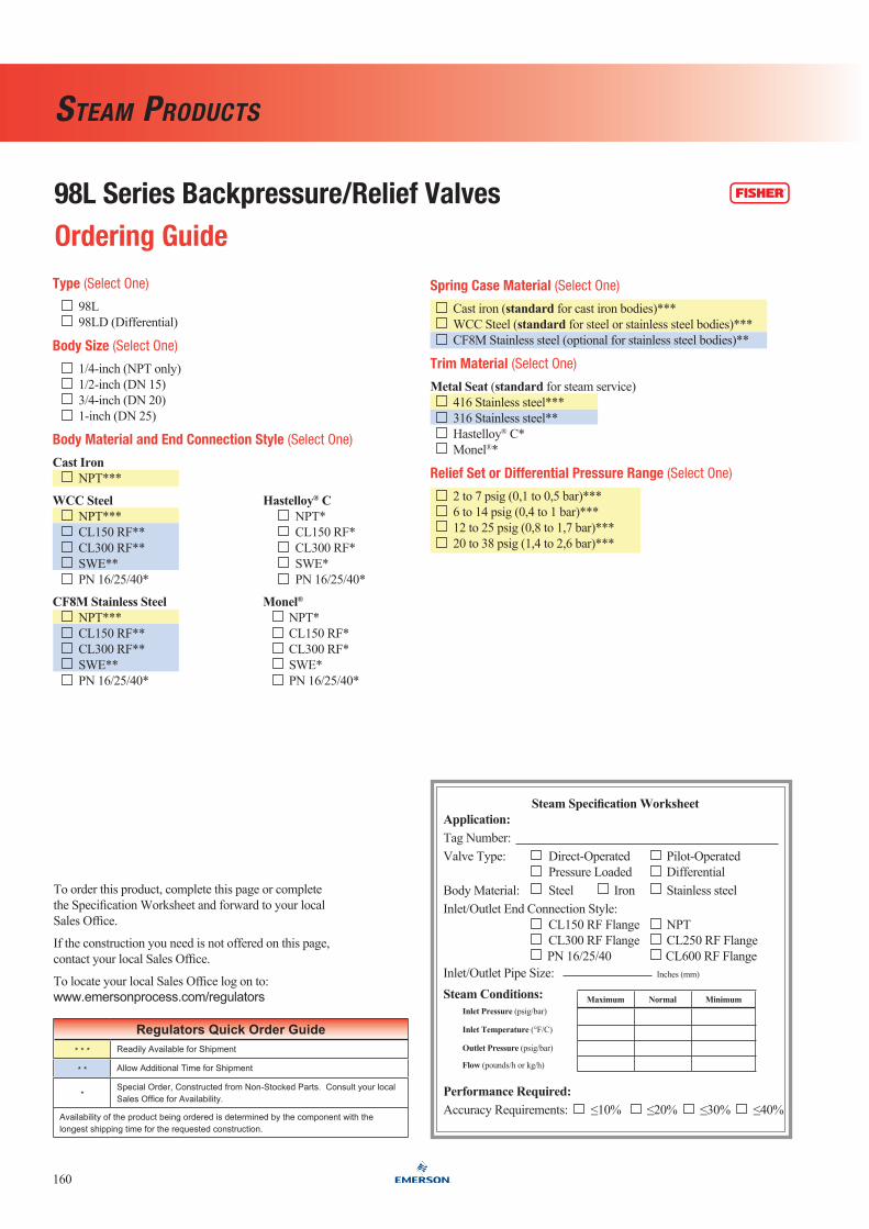
98l Series Backpressure/Relief Valves
160
Steam productS
ordering guide
Regulators Quick Order guide* * * Readily Available for Shipment
* * Allow Additional Time for Shipment
*Special Order, Constructed from Non-Stocked Parts. Consult your local Sales Office for Availability.
Availability of the product being ordered is determined by the component with the longest shipping time for the requested construction.
To order this product, complete this page or complete the Specification Worksheet and forward to your local Sales Office.
If the construction you need is not offered on this page, contact your local Sales Office.
To locate your local Sales Office log on to: www.emersonprocess.com/regulators
Steam Specification WorksheetApplication:Tag Number:Valve Type: Direct-Operated Pilot-Operated Pressure Loaded DifferentialBody Material: Steel Iron Stainless steelInlet/Outlet End Connection Style: CL150 RF Flange NPT CL300 RF Flange CL250 RF Flange PN 16/25/40 CL600 RF FlangeInlet/Outlet Pipe Size: Inches (mm)
SteamConditions: InletPressure(psig/bar)
InletTemperature(°F/C)
OutletPressure(psig/bar)
Flow(pounds/h or kg/h)
PerformanceRequired:Accuracy Requirements: ≤10% ≤20% ≤30% ≤40%
Maximum Normal Minimum
Spring case Material (Select One)
Cast iron (standard for cast iron bodies)*** WCC Steel (standard for steel or stainless steel bodies)*** CF8M Stainless steel (optional for stainless steel bodies)**
trim Material (Select One)
MetalSeat(standard for steam service) 416 Stainless steel*** 316 Stainless steel** Hastelloy® C* Monel®*
Relief Set or differential Pressure Range (Select One)
2 to 7 psig (0,1 to 0,5 bar)*** 6 to 14 psig (0,4 to 1 bar)*** 12 to 25 psig (0,8 to 1,7 bar)*** 20 to 38 psig (1,4 to 2,6 bar)***
type (Select One)
98L 98LD (Differential)
Body Size (Select One)
1/4-inch (NPT only) 1/2-inch (DN 15) 3/4-inch (DN 20) 1-inch (DN 25)
Body Material and End connection Style (Select One)
CastIron NPT***
WCC Steel Hastelloy®C NPT*** NPT* CL150 RF** CL150 RF* CL300 RF** CL300 RF* SWE** SWE* PN 16/25/40* PN 16/25/40*
CF8MStainlessSteel Monel®
NPT*** NPT* CL150 RF** CL150 RF* CL300 RF** CL300 RF* SWE** SWE* PN 16/25/40* PN 16/25/40*