AND ARRIVAL (STAR) CHARTS LEGEND - Indoavis charts are for training purposes only and not to be use...
12
2 nd Floor Terminal Building A-02/PK Halim Perdana Kusuma International Airport Jakarta (13610) INDONESIA Phone : 62-21-808 80028, 62-21-912 600238 Fax : 62-21-8097242 Website : http://www.indoavis.co.id - www.indoavis.net Email : [email protected] / [email protected] PT. INDOAVIS NUSANTARA Geo-informatics and Aeronautical Navigation Services These charts are for training purposes only and not to be use for flight INTRODUCTION TO INDOAVIS AERONAUTICAL NAVIGATION CHARTS USER’S GUIDE STANDARD INSTRUMENT DEPARTURE (SID) AND ARRIVAL (STAR) CHARTS LEGEND 8
Transcript of AND ARRIVAL (STAR) CHARTS LEGEND - Indoavis charts are for training purposes only and not to be use...

2nd Floor Terminal Building A-02/PK Halim Perdana Kusuma International AirportJakarta (13610) INDONESIAPhone : 62-21-808 80028, 62-21-912 600238Fax : 62-21-8097242Website : http://www.indoavis.co.id - www.indoavis.netEmail : [email protected] / [email protected]
PT. INDOAVIS NUSANTARAGeo-informatics and Aeronautical Navigation Services
These charts are for training purposes only
and not to be use for flight
INTRODUCTION TOINDOAVIS
AERONAUTICAL NAVIGATIONCHARTS USER’S GUIDE
STANDARD INSTRUMENT
DEPARTURE (SID)AND
ARRIVAL (STAR)
CHARTS LEGEND
8

DOC NO: INDOAVIS.UG.0I/III/2009
INTRODUCTION TO INDOAVIS AERONAUTICAL CHART USER’S GUIDE English Version
© INDOAVIS NUSANTARA

PT. INDOAVIS NUSANTARA Geo-informatics and Aeronautical Information Services.
SID/STAR CHART LEGEND [25 Oct 2009] II-10 8.1
7.1 SID/STAR USERS GUIDE | INTRODUCTION TO INDOAVIS NAVIGATION CHARTS
SID / STAR CHART LEGEND
GENERAL SID and STAR charts are graphic illustrations of the procedures prescribed by the governing authority. A text description may be provided, in addition to the graphic, when it is furnished by the governing authority. Not all items apply to all charts.
FUNCTION
STANDARD INSTRUMENT DEPARTURE (SID) Charts. This chart shall provide the
flight crew with information to enable it to comply with the designated standard departure route instrument from take-off phase to the en-route phase.
o Note 1.- Provisions governing the identification of standard departure routes are in Annex 11, Appendix 3 guidance material relating to the establishment of such routes is contained in the Air Traffic Services Planning Manual (Doc 9426).
o Note 2.- Provisions governing obstacle clearance criteria and details of the minimum information to be published are contained in the Procedures for Air Navigation Services - Aircraft Operations (PANS-OPS, Doc 8168), Volume II, Part II.
STANDARD TERMINAL ARRIVAL (STAR) Charts. This chart shall provide the flight
crew with information to enable it to comply with the designated standard arrival route — instrument from the en-route phase to the approach phase.
o Note 1 - Standard arrival routes — instrument are to be interpreted as including “standard descent profiles”,“ continuous descent approach”, and other non-standard descriptions. In the case of a standard descent profile, the depiction of a cross-section is not required.
o Note 2 - Provisions governing the identification of standard arrival routes are in Annex 11, Appendix 3; guidance material relating to the establishment of such routes Is contained in the Air Traffic Services Planning Manual (Doc 9426).

PT. INDOAVIS NUSANTARA Geo-informatics and Aeronautical Information Services.
SID/STAR CHART LEGEND [25 Oct 2009] II-10 8.2
7.2 SID/STAR USERS GUIDE | INTRODUCTION TO INDOAVIS NAVIGATION CHARTS
Coverage and scale The coverage of the chart shall be sufficient to indicate the point where the departure route begins and the specified significant point at which the en-route phase of flight along a designated air traffic services route can be commenced. Note.- The departure route normally originates at the end of a runway. Identification
The chart shall be identified by the name of the city or town, or area, which the aerodrome serves, the name of the aerodrome and the identification of the standard departure route(s) — instrument as established in accordance with the Procedures for Air Navigation Services — Aircraft Operations (PANS-OPS, Doc 8168), Volume II, Part
II, Chapter 5.
Note.— The identification of the standard departure route(s) — instrument is provided by the procedures specialist.
Recommendation
To improve situational awareness in areas where significant relief exists, the chart should be drawn to scale and all relief exceeding 300 m (1000 ft) above the aerodrome elevation should be shown by smoothed contour lines, contour values and layer tints printed in brown. Appropriate spot elevations, including the highest elevation within each top contour line, should be shown printed in black. Obstacles should also be shown.
Note 1.— The next higher suitable contour line appearing on base topographic maps exceeding 300 m (1000 ft) above the aerodrome elevation may be selected to start layer tinting.
Note 2.— An appropriate brown colour, on which half-tone layer tinting is to be based, is specified in Appendix 3 — Colour Guide for contours and topographic features.
Note 3.— Appropriate spot elevations and obstacles are those provided by the procedures specialist.
CORRECTIONS, COMMENTS
PT. Indoavis Nusantara 2nd Floor Terminal Building Halim Perdana Kusuma int'l Airport Jakarta - INDONESIA Telephone +62-21 808-800-28 Fax +62-21 809-72-42 Email : [email protected] / [email protected]
Frequently asked questions (FAQ) are answered on our website at : http://www.indoavis.co.id http://www.indoavis.net email : [email protected]
[email protected] See the FAQs prior to contact number or email.

PT. INDOAVIS NUSANTARA Geo-informatics and Aeronautical Information Services.
SID/STAR CHART LEGEND [25 Oct 2009] II-10 8.3
7.3 SID/STAR USERS GUIDE | INTRODUCTION TO INDOAVIS NAVIGATION CHARTS
GENERAL SID CHART FORMAT The step of Indoavis SID chart layout

PT. INDOAVIS NUSANTARA Geo-informatics and Aeronautical Information Services.
SID/STAR CHART LEGEND [25 Oct 2009] II-10 8.4
7.4 SID/STAR USERS GUIDE | INTRODUCTION TO INDOAVIS NAVIGATION CHARTS
GENERAL STAR CHART FORMAT The step of Indoavis STAR chart layout
PT. INDOAVIS NUSANTARA Geo-informatics and Aeronautical Information Services.
SID/STAR CHART LEGEND [25 Oct 2009] II-10 8.5
7.5 SID/STAR USERS GUIDE | INTRODUCTION TO INDOAVIS NAVIGATION CHARTS
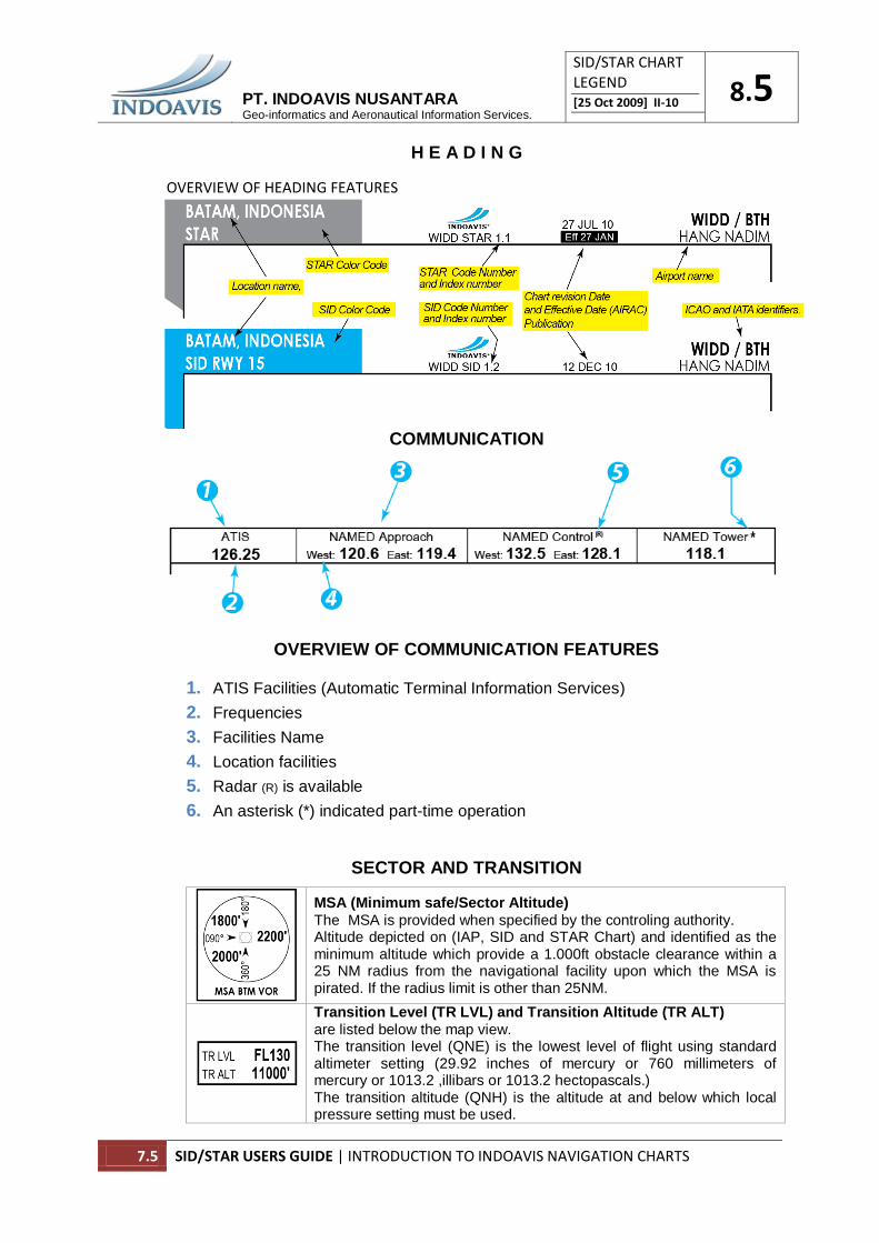
H E A D I N G
OVERVIEW OF HEADING FEATURES
COMMUNICATION
OVERVIEW OF COMMUNICATION FEATURES
1. ATIS Facilities (Automatic Terminal Information Services)
2. Frequencies
3. Facilities Name
4. Location facilities
5. Radar (R) is available
6. An asterisk (*) indicated part-time operation
SECTOR AND TRANSITION
MSA (Minimum safe/Sector Altitude)
The MSA is provided when specified by the controling authority. Altitude depicted on (IAP, SID and STAR Chart) and identified as the minimum altitude which provide a 1.000ft obstacle clearance within a 25 NM radius from the navigational facility upon which the MSA is pirated. If the radius limit is other than 25NM.
Transition Level (TR LVL) and Transition Altitude (TR ALT)
are listed below the map view. The transition level (QNE) is the lowest level of flight using standard altimeter setting (29.92 inches of mercury or 760 millimeters of mercury or 1013.2 ,illibars or 1013.2 hectopascals.) The transition altitude (QNH) is the altitude at and below which local pressure setting must be used.

PT. INDOAVIS NUSANTARA Geo-informatics and Aeronautical Information Services.
SID/STAR CHART LEGEND [25 Oct 2009] II-10 8.6
7.6 SID/STAR USERS GUIDE | INTRODUCTION TO INDOAVIS NAVIGATION CHARTS
SID/STAR CHART LEGEND MAP VIEW SYMBOLS
1. PROCEDURE TRACKS
Departure/Arrival procedure track
Missed approach procedure track
Radial line and value BR - (Bearing) R - (Radial) LR- (Lide Radial) hdg - (Heading) D - Distance
Track Transition Name Minimum En-route Altitude (MEA) Segment mileage
Airways Designator Flight level
Scale break
2. BEARING TRACKS
Magnetic course
True course
Magnetic heading
Magnetic radial
3. AIRPORT SYMBOLS
Primary SID/STAR Airport Airport Name and Elevation (MSL)
Secondary SID/STAR of Civil Airport
Secondary SID/STAR of Military Airport
Secondary SID/STAR of Join civil and Military Airport

PT. INDOAVIS NUSANTARA Geo-informatics and Aeronautical Information Services.
SID/STAR CHART LEGEND [25 Oct 2009] II-10 8.7
7.7 SID/STAR USERS GUIDE | INTRODUCTION TO INDOAVIS NAVIGATION CHARTS
4. RADIO NAVIGATION AIDS SYMBOLS
LOC/LDA/SDF/MLS
Transmitter (Shown when installation is offset from its normal position off the end of the runway)
LOC/DME Collocated LOC and DME radio navigation aids
VOR VHF omnidirectional radio range
NDB Non-directional radio beacon
TACAN Tactical air navigation aid
DME Distance measuring equipment
VOR/DME Collocated VOR and DME radio navigation aids
VORTAC Collocated VOR and TACAN radio navigation aids
Compass rose
Compass rose To be orientated on the chart in accordance with the alignment of the station (normally Magnetic North),
Compass rose to be used as appropriate in combination with the following symbols: (VOR, VOR/DME, TACAN, VORTAC)
5. RADIO NAVIGATION AIDS INFORMATION
ILS, LOC, LDA, SDF, MLS
(primary)
Navaid facility boxes include facility name, identifier, Morse code and frequency. The shadow indicates the primary facility. In VOR/DME and VORTAC facility boxes the letter “D” Indicate DME and “H” High Altitude when available.
VOR, VOR/DME (Primary)
NDB (Secondary)
6. ALTITUDE
MANDATORY Mandatory altitude in line cross at.
MINIMUM Minimum altitude in line cross at or above
MAXIMUM Maximum altitude in line cross at or below
RECOMMENDED Recomended altitude

PT. INDOAVIS NUSANTARA Geo-informatics and Aeronautical Information Services.
SID/STAR CHART LEGEND [25 Oct 2009] II-10 8.8
7.8 SID/STAR USERS GUIDE | INTRODUCTION TO INDOAVIS NAVIGATION CHARTS
7. AIRSPACE CLASSIFICATIONS
Airspace classification is designated by the letters (A) thru (G). Classification (A) represents the highest level of control and (G) represents uncontrolled airspace. The definition of each classification is found in the Glossary portion of this section and the En-route and Air Traffic Control section of this m a n u a l . The airspace classification letter is displayed in association with the airspace type and vertical limits.
CLASS A Airspace; Class A Airspace is the airspace from FL110 (11,000) feet
to FL130 (13,000). All pilots flying in Class A airspace shall file an Instrument Flight Rules (IFR) flight plan and receive an appropriate air traffic control (ATC) clearance. When climbing through 11,000 feet, the pilot will change the altimeter setting from the local altimeter (30.01 for example) to 29.92. This ensures all aircraft flying in class A airspace have the same altimeter setting and will have proper altitude separation.
CLASS B Airspace; Class B Airspace is generally the airspace from the
surface to 10,000 feet. This airspace is normally around the busiest airports in terms of aircraft traffic. Class B airspace is individually designed to meet the needs of the particular airport and consists of a surface area and two more layers. Most Class B airspace resemble an upside down wedding cake. Pilots must contact air traffic control to receive an air traffic control clearance to enter Class B airspace. Once a pilot receives an air traffic control clearance, they receive separation services from other aircraft within the airspace.
CLASS C Airspace; Class C Airspace is the airspace from the surface to 4,000
feet above the airport elevation. Class C airspace will only be found at airports that have an operational control tower, are serviced by a radar approach control, and that have a certain number of IFR operations. Although Class C airspace is individually tailored to meet the needs of the airport, the airspace usually consists of a surface area with a 5 nautical mile (NM) radius, an outer circle with a 10 NM radius that extends from 1,200 feet to 4,000 feet above the airport elevation and an outer area. Pilots must establish and maintain two-way radio communications with the ATC facility providing air traffic control services prior to entering airspace. Pilots of visual flight rules (VFR) aircraft are separated from pilots of instrument flight rules (IFR) aircraft only. Anchorage International airport.
CLASS D Airspace; Definition. Generally, that airspace from the surface to
2,500 feet above the airport elevation (charted in MSL) surrounding those airports that have an operational control tower. The configuration of each Class D airspace area is individually tailored and when instrument procedures are published, the airspace will normally be designed to contain the procedures.

PT. INDOAVIS NUSANTARA Geo-informatics and Aeronautical Information Services.
SID/STAR CHART LEGEND [25 Oct 2009] II-10 8.9
7.9 SID/STAR USERS GUIDE | INTRODUCTION TO INDOAVIS NAVIGATION CHARTS
8. RESTRICTED AIRSPACE
Restricted airspace. The accompanying label indicates it as prohibited, restricted, danger, etc. (T) Training, (A) Alert, (C) Caution, and Military Operations Areas.
WI Country identifier WI : Indonesia, WS : Singapore WM : Malaysia YB : Australia (R) Restricted ________ 121 designation number UNL Unlimited (Upper Limit) GND Ground (Lower Limit) 0800-2200 Hours active MON-SAT Day active IND-ARTC Controling Agency
(A) Alert (T) Training (C) Caution (W) Warning (D) Danger (P) Prohibited (R) Restricted (TRA) Temporary Reserved Airspace (TSA) Temporary Segregated Area
(MOA) Military Operations Area
9. AIRSPACE FIXES
RPC Reporting Point (Compulsory)
RPR Reporting Point (On-Request)
RNAV RNAV Point (Compulsory)
RNAV RNAV Point (On-Request)
DME DME Distance
MB Mileage Breakdown
WPT Flyover Waypoint
WPT Fly-by Waypoint
DME info
DME value Navaid name
FIX POINT Info
Fixes Point Name Coordinates are shown
10. MAGNETIC BEARING
Bearing magnetic variation Magnetic declination is the angle between magnetic north (the direction the north end of a compass needle points) and true north. The declination is positive when the magnetic north is east of true north. The term magnetic variation is a synonym

PT. INDOAVIS NUSANTARA Geo-informatics and Aeronautical Information Services.
SID/STAR CHART LEGEND [25 Oct 2009] II-10 8.10
7.10 SID/STAR USERS GUIDE | INTRODUCTION TO INDOAVIS NAVIGATION CHARTS
11. TERRAIN HIGH POINT (OBSTACLE)
Spot Elevation
Mean Sea Level (MSL) elevation at top of terrain high point/man-made structure.
Spot Elevation unsurveyed accuracy
Spot highest elevation
Box indicates only the highest of portrayed terrain high point and man-made structures may exist which have not been portrayed.
Generalized terrain contour information. The Gradient tints indicate the elevation change between contour intervals