and 1-5Vdc Low Power Protocol - Emerson · Reference Manual 00809-0100-4108, Rev CB November 2017...
98
Reference Manual 00809-0100-4108, Rev CB November 2017 Rosemount ™ 2088, 2090P, and 2090F Pressure Transmitters with HART ® and 1-5Vdc Low Power Protocol
Transcript of and 1-5Vdc Low Power Protocol - Emerson · Reference Manual 00809-0100-4108, Rev CB November 2017...

Reference Manual00809-0100-4108, Rev CB
November 2017
Rosemount™ 2088, 2090P, and 2090F Pressure Transmitterswith HART® and 1-5Vdc Low Power Protocol


Reference Manual 00809-0100-4108, Rev CB
ContentsNovember 2017
Contents
1Section 1: Introduction1.1 Using this manual. . . . . . . . . . . . . . . . . . . . . . . . . . . . . . . . . . . . . . . . . . . . . . . . . . . . . . 1
1.2 Models covered . . . . . . . . . . . . . . . . . . . . . . . . . . . . . . . . . . . . . . . . . . . . . . . . . . . . . . . 2
1.2.1 Rosemount 2088G Gage Pressure Transmitter. . . . . . . . . . . . . . . . . . . . . . . 2
1.2.2 Rosemount 2088A Absolute Pressure Transmitter . . . . . . . . . . . . . . . . . . . 2
1.2.3 Rosemount 2090F Hygienic Pressure Transmitter . . . . . . . . . . . . . . . . . . . . 2
1.2.4 Rosemount 2090P Pulp and Paper Pressure Transmitter . . . . . . . . . . . . . . 2
1.3 Product recycling/disposal . . . . . . . . . . . . . . . . . . . . . . . . . . . . . . . . . . . . . . . . . . . . . . 2
2Section 2: Configuration2.1 Safety messages . . . . . . . . . . . . . . . . . . . . . . . . . . . . . . . . . . . . . . . . . . . . . . . . . . . . . . . 3
2.2 System readiness . . . . . . . . . . . . . . . . . . . . . . . . . . . . . . . . . . . . . . . . . . . . . . . . . . . . . . 3
2.2.1 Confirm correct device driver . . . . . . . . . . . . . . . . . . . . . . . . . . . . . . . . . . . . . . 3
2.3 HART installation flowchart . . . . . . . . . . . . . . . . . . . . . . . . . . . . . . . . . . . . . . . . . . . . . 5
2.4 Transmitter overview . . . . . . . . . . . . . . . . . . . . . . . . . . . . . . . . . . . . . . . . . . . . . . . . . . 6
2.5 Configuration overview. . . . . . . . . . . . . . . . . . . . . . . . . . . . . . . . . . . . . . . . . . . . . . . . . 8
2.6 Configuration basics . . . . . . . . . . . . . . . . . . . . . . . . . . . . . . . . . . . . . . . . . . . . . . . . . . . 8
2.6.1 Configuring on the bench . . . . . . . . . . . . . . . . . . . . . . . . . . . . . . . . . . . . . . . . . 8
2.6.2 Configuration tools. . . . . . . . . . . . . . . . . . . . . . . . . . . . . . . . . . . . . . . . . . . . . . . 9
2.6.3 Setting the loop to manual . . . . . . . . . . . . . . . . . . . . . . . . . . . . . . . . . . . . . . . 11
2.7 Verify configuration . . . . . . . . . . . . . . . . . . . . . . . . . . . . . . . . . . . . . . . . . . . . . . . . . . . 11
2.7.1 Verifying configuration with Field Communicator . . . . . . . . . . . . . . . . . . . 11
2.7.2 Verifying configuration with AMS Device Manager . . . . . . . . . . . . . . . . . . 12
2.7.3 Verifying configuration with local operator interface . . . . . . . . . . . . . . . . 12
2.7.4 Verifying process variables configuration . . . . . . . . . . . . . . . . . . . . . . . . . . 12
2.8 Basic setup of the transmitter . . . . . . . . . . . . . . . . . . . . . . . . . . . . . . . . . . . . . . . . . . 12
2.8.1 Setting pressure units . . . . . . . . . . . . . . . . . . . . . . . . . . . . . . . . . . . . . . . . . . . 13
2.8.2 Rerange the transmitter . . . . . . . . . . . . . . . . . . . . . . . . . . . . . . . . . . . . . . . . . 13
2.8.3 Damping. . . . . . . . . . . . . . . . . . . . . . . . . . . . . . . . . . . . . . . . . . . . . . . . . . . . . . . 16
2.9 Configuring the LCD display. . . . . . . . . . . . . . . . . . . . . . . . . . . . . . . . . . . . . . . . . . . . 17
2.10 Detailed transmitter setup . . . . . . . . . . . . . . . . . . . . . . . . . . . . . . . . . . . . . . . . . . . . 18
2.10.1Configuring alarm and saturation levels . . . . . . . . . . . . . . . . . . . . . . . . . . . 18
2.10.2 Configuring scaled variable . . . . . . . . . . . . . . . . . . . . . . . . . . . . . . . . . . . . . . 19
2.10.3 Re-mapping device variables. . . . . . . . . . . . . . . . . . . . . . . . . . . . . . . . . . . . . 21
2.11 Performing transmitter tests . . . . . . . . . . . . . . . . . . . . . . . . . . . . . . . . . . . . . . . . . . 23
1Contents
2
Reference Manual00809-0100-4108, Rev CB
ContentsNovember 2017
2.11.1 Verifying alarm level. . . . . . . . . . . . . . . . . . . . . . . . . . . . . . . . . . . . . . . . . . . . 23
2.11.2 Performing an analog loop test . . . . . . . . . . . . . . . . . . . . . . . . . . . . . . . . . . 23
2.11.3 Simulate device variables . . . . . . . . . . . . . . . . . . . . . . . . . . . . . . . . . . . . . . . 24
2.12 Configuring burst mode . . . . . . . . . . . . . . . . . . . . . . . . . . . . . . . . . . . . . . . . . . . . . . 24
2.13 Establishing multidrop communication . . . . . . . . . . . . . . . . . . . . . . . . . . . . . . . . 26
2.13.1 Changing a transmitter address . . . . . . . . . . . . . . . . . . . . . . . . . . . . . . . . . . 26
2.13.2 Communicating with a multidropped transmitter . . . . . . . . . . . . . . . . . . 27
3Section 3: Hardware installation3.1 Overview . . . . . . . . . . . . . . . . . . . . . . . . . . . . . . . . . . . . . . . . . . . . . . . . . . . . . . . . . . . . 29
3.2 Safety messages . . . . . . . . . . . . . . . . . . . . . . . . . . . . . . . . . . . . . . . . . . . . . . . . . . . . . . 29
3.3 Considerations . . . . . . . . . . . . . . . . . . . . . . . . . . . . . . . . . . . . . . . . . . . . . . . . . . . . . . . 30
3.3.1 Installation considerations . . . . . . . . . . . . . . . . . . . . . . . . . . . . . . . . . . . . . . . 30
3.3.2 Environmental considerations . . . . . . . . . . . . . . . . . . . . . . . . . . . . . . . . . . . . 31
3.3.3 Mechanical considerations . . . . . . . . . . . . . . . . . . . . . . . . . . . . . . . . . . . . . . . 31
3.4 Installation procedures . . . . . . . . . . . . . . . . . . . . . . . . . . . . . . . . . . . . . . . . . . . . . . . . 31
3.4.1 Mount the transmitter . . . . . . . . . . . . . . . . . . . . . . . . . . . . . . . . . . . . . . . . . . . 31
3.4.2 Impulse piping. . . . . . . . . . . . . . . . . . . . . . . . . . . . . . . . . . . . . . . . . . . . . . . . . . 35
3.4.3 Process connections. . . . . . . . . . . . . . . . . . . . . . . . . . . . . . . . . . . . . . . . . . . . . 37
3.4.4 Inline process connection . . . . . . . . . . . . . . . . . . . . . . . . . . . . . . . . . . . . . . . . 37
3.5 Process connections . . . . . . . . . . . . . . . . . . . . . . . . . . . . . . . . . . . . . . . . . . . . . . . . . . 38
3.5.1 Rosemount 2090P . . . . . . . . . . . . . . . . . . . . . . . . . . . . . . . . . . . . . . . . . . . . . . 38
3.5.2 Weld spud . . . . . . . . . . . . . . . . . . . . . . . . . . . . . . . . . . . . . . . . . . . . . . . . . . . . . 39
3.5.3 Transmitter . . . . . . . . . . . . . . . . . . . . . . . . . . . . . . . . . . . . . . . . . . . . . . . . . . . . 39
3.6 Rosemount 306 Manifold . . . . . . . . . . . . . . . . . . . . . . . . . . . . . . . . . . . . . . . . . . . . . . 40
3.6.1 Rosemount 306 Integral Manifold installation procedure . . . . . . . . . . . . 40
4Section 4: Electrical installation4.1 Overview . . . . . . . . . . . . . . . . . . . . . . . . . . . . . . . . . . . . . . . . . . . . . . . . . . . . . . . . . . . . 41
4.2 Safety messages . . . . . . . . . . . . . . . . . . . . . . . . . . . . . . . . . . . . . . . . . . . . . . . . . . . . . . 41
4.3 Local Operating Interface (LOI)/LCD display . . . . . . . . . . . . . . . . . . . . . . . . . . . . . . 42
4.3.1 Rotating LCD/LOI display. . . . . . . . . . . . . . . . . . . . . . . . . . . . . . . . . . . . . . . . . 42
4.4 Configuring transmitter security. . . . . . . . . . . . . . . . . . . . . . . . . . . . . . . . . . . . . . . . 43
4.4.1 Setting security switch. . . . . . . . . . . . . . . . . . . . . . . . . . . . . . . . . . . . . . . . . . . 43
4.4.2 HART lock . . . . . . . . . . . . . . . . . . . . . . . . . . . . . . . . . . . . . . . . . . . . . . . . . . . . . . 44
4.4.3 Configuration button lock. . . . . . . . . . . . . . . . . . . . . . . . . . . . . . . . . . . . . . . . 44
4.4.4 LOI password . . . . . . . . . . . . . . . . . . . . . . . . . . . . . . . . . . . . . . . . . . . . . . . . . . . 44
4.5 Setting transmitter alarm . . . . . . . . . . . . . . . . . . . . . . . . . . . . . . . . . . . . . . . . . . . . . . 45
Contents

Reference Manual 00809-0100-4108, Rev CB
ContentsNovember 2017
4.6 Electrical considerations . . . . . . . . . . . . . . . . . . . . . . . . . . . . . . . . . . . . . . . . . . . . . . . 46
4.6.1 Conduit installation . . . . . . . . . . . . . . . . . . . . . . . . . . . . . . . . . . . . . . . . . . . . . 46
4.6.2 Power supply . . . . . . . . . . . . . . . . . . . . . . . . . . . . . . . . . . . . . . . . . . . . . . . . . . . 46
4.6.3 Wiring the transmitter . . . . . . . . . . . . . . . . . . . . . . . . . . . . . . . . . . . . . . . . . . . 47
4.6.4 Grounding the transmitter . . . . . . . . . . . . . . . . . . . . . . . . . . . . . . . . . . . . . . . 49
5Section 5: Operation and maintenance5.1 Overview . . . . . . . . . . . . . . . . . . . . . . . . . . . . . . . . . . . . . . . . . . . . . . . . . . . . . . . . . . . . 53
5.2 Safety messages . . . . . . . . . . . . . . . . . . . . . . . . . . . . . . . . . . . . . . . . . . . . . . . . . . . . . . 53
5.3 Recommended calibration tasks . . . . . . . . . . . . . . . . . . . . . . . . . . . . . . . . . . . . . . . . 54
5.3.1 Field installation tasks . . . . . . . . . . . . . . . . . . . . . . . . . . . . . . . . . . . . . . . . . . . 54
5.3.2 Bench calibration tasks . . . . . . . . . . . . . . . . . . . . . . . . . . . . . . . . . . . . . . . . . . 54
5.4 Calibration overview . . . . . . . . . . . . . . . . . . . . . . . . . . . . . . . . . . . . . . . . . . . . . . . . . . 54
5.4.1 Determining necessary sensor trims. . . . . . . . . . . . . . . . . . . . . . . . . . . . . . . 55
5.4.2 Determining calibration frequency . . . . . . . . . . . . . . . . . . . . . . . . . . . . . . . . 56
5.5 Trim the pressure signal . . . . . . . . . . . . . . . . . . . . . . . . . . . . . . . . . . . . . . . . . . . . . . . 56
5.5.1 Sensor trim overview . . . . . . . . . . . . . . . . . . . . . . . . . . . . . . . . . . . . . . . . . . . . 56
5.5.2 Perform a sensor trim. . . . . . . . . . . . . . . . . . . . . . . . . . . . . . . . . . . . . . . . . . . . 57
5.5.3 Recall factory trim—sensor trim . . . . . . . . . . . . . . . . . . . . . . . . . . . . . . . . . . . 59
5.6 Trim the analog output . . . . . . . . . . . . . . . . . . . . . . . . . . . . . . . . . . . . . . . . . . . . . . . . 60
5.6.1 Performing digital-to-analog trim (4–20mA/ 1–5 V output trim) . . . . . . 60
5.6.2 Performing digital-to-analog trim (4–20mA/ 1–5 V output trim) using oth-er scale . . . . . . . . . . . . . . . . . . . . . . . . . . . . . . . . . . . . . . . . . . . . . . . . . . . . . . . . 61
5.6.3 Recalling factory trim—analog output . . . . . . . . . . . . . . . . . . . . . . . . . . . . . 62
5.7 Switching HART revision . . . . . . . . . . . . . . . . . . . . . . . . . . . . . . . . . . . . . . . . . . . . . . . 63
5.7.1 Switching HART revision with generic menu . . . . . . . . . . . . . . . . . . . . . . . . 63
5.7.2 Switching HART revision with Field Communicator . . . . . . . . . . . . . . . . . . 63
5.7.3 Switching HART revision with AMS Device Manager . . . . . . . . . . . . . . . . . 63
5.7.4 Switching HART revision with LOI . . . . . . . . . . . . . . . . . . . . . . . . . . . . . . . . . 64
6Section 6: Troubleshooting6.1 Overview . . . . . . . . . . . . . . . . . . . . . . . . . . . . . . . . . . . . . . . . . . . . . . . . . . . . . . . . . . . . 65
6.2 Safety messages . . . . . . . . . . . . . . . . . . . . . . . . . . . . . . . . . . . . . . . . . . . . . . . . . . . . . . 65
6.3 Diagnostic messages . . . . . . . . . . . . . . . . . . . . . . . . . . . . . . . . . . . . . . . . . . . . . . . . . . 68
6.4 Disassembly procedures . . . . . . . . . . . . . . . . . . . . . . . . . . . . . . . . . . . . . . . . . . . . . . . 70
6.4.1 Removing from service . . . . . . . . . . . . . . . . . . . . . . . . . . . . . . . . . . . . . . . . . . 70
6.4.2 Removing terminal block . . . . . . . . . . . . . . . . . . . . . . . . . . . . . . . . . . . . . . . . 71
6.4.3 Removing the LOI or LCD display . . . . . . . . . . . . . . . . . . . . . . . . . . . . . . . . . . 71
3Contents

4
Reference Manual00809-0100-4108, Rev CB
ContentsNovember 2017
6.5 Reassembly procedures . . . . . . . . . . . . . . . . . . . . . . . . . . . . . . . . . . . . . . . . . . . . . . . 72
6.5.1 Installing LOI/LCD Display . . . . . . . . . . . . . . . . . . . . . . . . . . . . . . . . . . . . . . . . 72
6.6 Service support . . . . . . . . . . . . . . . . . . . . . . . . . . . . . . . . . . . . . . . . . . . . . . . . . . . . . . . 72
AAppendix A: Specifications and reference dataA.1 Performance specifications . . . . . . . . . . . . . . . . . . . . . . . . . . . . . . . . . . . . . . . . . . . . 73
A.1.1 Reference accuracy . . . . . . . . . . . . . . . . . . . . . . . . . . . . . . . . . . . . . . . . . . . . . 73
A.1.2 Long term stability . . . . . . . . . . . . . . . . . . . . . . . . . . . . . . . . . . . . . . . . . . . . . . 73
A.1.3 Dynamic performance . . . . . . . . . . . . . . . . . . . . . . . . . . . . . . . . . . . . . . . . . . . 73
A.1.4 Ambient temperature effects. . . . . . . . . . . . . . . . . . . . . . . . . . . . . . . . . . . . . 73
A.1.5 Mounting position effects . . . . . . . . . . . . . . . . . . . . . . . . . . . . . . . . . . . . . . . . 73
A.1.6 Vibration effect . . . . . . . . . . . . . . . . . . . . . . . . . . . . . . . . . . . . . . . . . . . . . . . . . 73
A.1.7 Transient protection (option code T1) . . . . . . . . . . . . . . . . . . . . . . . . . . . . . 74
A.2 Functional specifications . . . . . . . . . . . . . . . . . . . . . . . . . . . . . . . . . . . . . . . . . . . . . . 74
A.2.1 Service. . . . . . . . . . . . . . . . . . . . . . . . . . . . . . . . . . . . . . . . . . . . . . . . . . . . . . . . . 74
A.3 Pressure range values . . . . . . . . . . . . . . . . . . . . . . . . . . . . . . . . . . . . . . . . . . . . . . . . . 74
A.3.1 Output protocols . . . . . . . . . . . . . . . . . . . . . . . . . . . . . . . . . . . . . . . . . . . . . . . 74
A.3.2 4-20mA selectable HART protocol (output code S) . . . . . . . . . . . . . . . . . . 74
A.3.3 1-5 Vdc HART low power (output code N for 2088 only) . . . . . . . . . . . . . 75
A.3.4 Overpressure limits. . . . . . . . . . . . . . . . . . . . . . . . . . . . . . . . . . . . . . . . . . . . . . 76
A.3.5 Burst pressure limits . . . . . . . . . . . . . . . . . . . . . . . . . . . . . . . . . . . . . . . . . . . . . 76
A.3.6 Failure mode alarm. . . . . . . . . . . . . . . . . . . . . . . . . . . . . . . . . . . . . . . . . . . . . . 76
A.3.7 Temperature limits. . . . . . . . . . . . . . . . . . . . . . . . . . . . . . . . . . . . . . . . . . . . . . 76
A.3.8 Physical specifications . . . . . . . . . . . . . . . . . . . . . . . . . . . . . . . . . . . . . . . . . . . 77
A.3.9 Process connections. . . . . . . . . . . . . . . . . . . . . . . . . . . . . . . . . . . . . . . . . . . . . 77
A.3.10 Process wetted parts . . . . . . . . . . . . . . . . . . . . . . . . . . . . . . . . . . . . . . . . . . . 77
A.3.11 Non-wetted parts . . . . . . . . . . . . . . . . . . . . . . . . . . . . . . . . . . . . . . . . . . . . . . 78
A.3.12 Shipping weights . . . . . . . . . . . . . . . . . . . . . . . . . . . . . . . . . . . . . . . . . . . . . . 78
A.4 Dimensional drawings. . . . . . . . . . . . . . . . . . . . . . . . . . . . . . . . . . . . . . . . . . . . . . . . . 79
A.5 Ordering information . . . . . . . . . . . . . . . . . . . . . . . . . . . . . . . . . . . . . . . . . . . . . . . . . 81
A.6 Options. . . . . . . . . . . . . . . . . . . . . . . . . . . . . . . . . . . . . . . . . . . . . . . . . . . . . . . . . . . . . . 90
BAppendix B: Product CertificationsB.1 Rosemount™ 2088 product certifications . . . . . . . . . . . . . . . . . . . . . . . . . . . . . . . . 93
B.1.1 European Directive Information. . . . . . . . . . . . . . . . . . . . . . . . . . . . . . . . . . . 93
B.1.2 Ordinary Location Certification . . . . . . . . . . . . . . . . . . . . . . . . . . . . . . . . . . . 93
B.1.3 North America . . . . . . . . . . . . . . . . . . . . . . . . . . . . . . . . . . . . . . . . . . . . . . . . . . 93
B.1.4 Europe. . . . . . . . . . . . . . . . . . . . . . . . . . . . . . . . . . . . . . . . . . . . . . . . . . . . . . . . . 93
Contents
Reference Manual 00809-0100-4108, Rev CB
ContentsNovember 2017
B.1.5 International . . . . . . . . . . . . . . . . . . . . . . . . . . . . . . . . . . . . . . . . . . . . . . . . . . . 94
B.1.6 Brazil . . . . . . . . . . . . . . . . . . . . . . . . . . . . . . . . . . . . . . . . . . . . . . . . . . . . . . . . . . 95
B.1.7 China . . . . . . . . . . . . . . . . . . . . . . . . . . . . . . . . . . . . . . . . . . . . . . . . . . . . . . . . . . 95
B.1.8 Japan . . . . . . . . . . . . . . . . . . . . . . . . . . . . . . . . . . . . . . . . . . . . . . . . . . . . . . . . . . 96
B.1.9 Technical Regulations Customs Union (EAC). . . . . . . . . . . . . . . . . . . . . . . . 97
B.1.10 Combinations . . . . . . . . . . . . . . . . . . . . . . . . . . . . . . . . . . . . . . . . . . . . . . . . . 97
B.1.11 Conduit Plugs and Adapters . . . . . . . . . . . . . . . . . . . . . . . . . . . . . . . . . . . . . 97
B.1.12 Additional Certifications . . . . . . . . . . . . . . . . . . . . . . . . . . . . . . . . . . . . . . . . 97
B.2 Rosemount 2090 product certification . . . . . . . . . . . . . . . . . . . . . . . . . . . . . . . . . . 98
B.2.1 European Directive Information. . . . . . . . . . . . . . . . . . . . . . . . . . . . . . . . . . . 98
B.2.2 Ordinary Location Certification . . . . . . . . . . . . . . . . . . . . . . . . . . . . . . . . . . . 98
B.2.3 North America . . . . . . . . . . . . . . . . . . . . . . . . . . . . . . . . . . . . . . . . . . . . . . . . . . 98
B.2.4 Europe. . . . . . . . . . . . . . . . . . . . . . . . . . . . . . . . . . . . . . . . . . . . . . . . . . . . . . . . . 98
B.2.5 International . . . . . . . . . . . . . . . . . . . . . . . . . . . . . . . . . . . . . . . . . . . . . . . . . . . 99
B.2.6 China . . . . . . . . . . . . . . . . . . . . . . . . . . . . . . . . . . . . . . . . . . . . . . . . . . . . . . . . . 100
B.2.7 Technical Regulations Customs Union (EAC). . . . . . . . . . . . . . . . . . . . . . . 101
B.2.8 Combinations . . . . . . . . . . . . . . . . . . . . . . . . . . . . . . . . . . . . . . . . . . . . . . . . . 101
B.2.9 Conduit plugs and adapters . . . . . . . . . . . . . . . . . . . . . . . . . . . . . . . . . . . . . 101
B.3 Installation drawings . . . . . . . . . . . . . . . . . . . . . . . . . . . . . . . . . . . . . . . . . . . . . . . . . 103
B.3.1 Factory mutual 02088-1018. . . . . . . . . . . . . . . . . . . . . . . . . . . . . . . . . . . . . 103
B.3.2 Canadian standards association (CSA) 02088-1024. . . . . . . . . . . . . . . . . 109
CAppendix C: Field Communicator menu trees and Fast KeysC.1 Field communicator menu trees . . . . . . . . . . . . . . . . . . . . . . . . . . . . . . . . . . . . . . . 113
C.2 Field communicator Fast Keys . . . . . . . . . . . . . . . . . . . . . . . . . . . . . . . . . . . . . . . . . 117
DAppendix D: Local Operator Interface D.1 LOI menu tree . . . . . . . . . . . . . . . . . . . . . . . . . . . . . . . . . . . . . . . . . . . . . . . . . . . . . . . 119
D.2 LOI menu tree - extended menu . . . . . . . . . . . . . . . . . . . . . . . . . . . . . . . . . . . . . . . 120
D.3 Number entry . . . . . . . . . . . . . . . . . . . . . . . . . . . . . . . . . . . . . . . . . . . . . . . . . . . . . . . 121
D.4 Text entry. . . . . . . . . . . . . . . . . . . . . . . . . . . . . . . . . . . . . . . . . . . . . . . . . . . . . . . . . . . 122
5Contents

6
Reference Manual00809-0100-4108, Rev CB
ContentsNovember 2017
Contents

Reference Manual 00809-0100-4108, Rev CB
Title PageNovember 2017
Rosemount™ 2088, 2090P, and 2090F Pressure Transmitters
Read this manual before working with the product. For personal and system safety, and for optimum product performance, make sure you thoroughly understand the contents before installing, using, or maintaining this product.
For technical assistance, contacts are listed below:
Customer CentralTechnical support, quoting, and order-related questions.
United States - 1-800-999-9307 (7:00 am to 7:00 pm CST)
Asia Pacific- 65 777 8211
Europe Middle East Africa - 49 (8153) 9390
North American Response CenterEquipment service needs.
1-800-654-7768 (24 hours—includes Canada)
Outside of these areas, contact your local Emerson™ representative.
The products described in this document are NOT designed for nuclear-qualified applications. Using non-nuclear qualified products in applications that require nuclear-qualified hardware or products may cause inaccurate readings.
For information on Rosemount nuclear-qualified products, contact your local Emerson Sales Representative.
iiiTitle Page

Reference Manual00809-0100-4108, Rev CB
Title PageNovember 2017
Explosions could result in death or serious injury.
Installation of this transmitter in an explosive environment must be in accordance with the appropriate local, national, and international standards, codes, and practices. Review the approvals section of the Rosemount 2088, 2090F, 2090P reference manual for any restrictions associated with a safe installation. Before connecting a Field Communicator in an explosive atmosphere, ensure the
instruments in the loop are installed in accordance with intrinsically safe or non-incendive field wiring practices.
In an explosion-proof/flameproof installation, do not remove the transmitter covers when power is applied to the unit.
Process leaks may cause harm or result in death.
Install and tighten process connectors before applying pressure.Electrical shock can result in death or serious injury.
Avoid contact with the leads and terminals. High voltage that may be present on leads can cause electrical shock.
iv Title Page

Reference Manual 00809-0100-4108, Rev CB
IntroductionNovember 2017
Section 1 Introduction
1.1 Using this manualThe sections in this manual provide information on installing, operating, and maintaining the Rosemount™ 2088, 2090F, and 2090P. The sections are organized as follows:
Section 2: Configuration provides instruction on commissioning and operating Rosemount 2088 Transmitters. Information on software functions, configuration parameters, and online variables is also included.
Section 3: Hardware installation contains mechanical installation instructions, and field upgrade options.
Section 4: Electrical installation contains electrical installation instructions, and field upgrade options.
Section 5: Operation and maintenance provides detailed information on calibrating and changing HART® Revisions.
Section 6: Troubleshooting provides troubleshooting techniques for the most common operating problems.
Appendix A: Reference data supplies reference and specification data, as well as ordering information.
Appendix B: Field Communicator menu trees and Fast Keys provides full menu trees and abbreviated Fast Key sequences for commissioning tasks.
Appendix C: Local Operator Interface provides detailed Local Operating Interface (LOI) menu trees.
1Introduction

Reference Manual00809-0100-4108, Rev CB
IntroductionNovember 2017
1.2 Models coveredThe following Rosemount Pressure Transmitters are covered by this manual:
1.2.1 Rosemount 2088G Gage Pressure Transmitter Measures gage pressure up to 4000 psi (275,8 bar)
1.2.2 Rosemount 2088A Absolute Pressure Transmitter Measures absolute pressure up to 4000 psi (275,8 bar)
1.2.3 Rosemount 2090F Hygienic Pressure Transmitter
Rosemount 2090FG - Gage Pressure Transmitter Measures gage pressure up to 300 psi (20,7 bar)
Rosemount 2090FA - Absolute Pressure Transmitter Measures absolute pressure up to 300 psi (20,7 bar)
1.2.4 Rosemount 2090P Pulp and Paper Pressure Transmitter
Rosemount 2090PG - Gage Pressure Transmitter Measures gage pressure up to 300 psi (20,7 bar)
Rosemount 2090PA - Absolute Pressure Transmitter Measures gage pressure up to 300 psi (20,7 bar)
1.3 Product recycling/disposalRecycling of equipment and packaging should be taken into consideration and disposed of in accordance with local and national legislation/regulations.
2 Introduction

Reference Manual 00809-0100-4108, Rev CB
ConfigurationNovember 2017
Section 2 Configuration
Safety messages . . . . . . . . . . . . . . . . . . . . . . . . . . . . . . . . . . . . . . . . . . . . . . . . . . . . . . . . . . page 3System readiness . . . . . . . . . . . . . . . . . . . . . . . . . . . . . . . . . . . . . . . . . . . . . . . . . . . . . . . . . page 3HART installation flowchart . . . . . . . . . . . . . . . . . . . . . . . . . . . . . . . . . . . . . . . . . . . . . . . . page 5Transmitter overview . . . . . . . . . . . . . . . . . . . . . . . . . . . . . . . . . . . . . . . . . . . . . . . . . . . . . . page 6Configuration overview . . . . . . . . . . . . . . . . . . . . . . . . . . . . . . . . . . . . . . . . . . . . . . . . . . . . page 8Configuration basics . . . . . . . . . . . . . . . . . . . . . . . . . . . . . . . . . . . . . . . . . . . . . . . . . . . . . . page 8Verify configuration . . . . . . . . . . . . . . . . . . . . . . . . . . . . . . . . . . . . . . . . . . . . . . . . . . . . . . . page 11Basic setup of the transmitter . . . . . . . . . . . . . . . . . . . . . . . . . . . . . . . . . . . . . . . . . . . . . . page 12Configuring the LCD display . . . . . . . . . . . . . . . . . . . . . . . . . . . . . . . . . . . . . . . . . . . . . . . . page 17Detailed transmitter setup . . . . . . . . . . . . . . . . . . . . . . . . . . . . . . . . . . . . . . . . . . . . . . . . . page 18Performing transmitter tests . . . . . . . . . . . . . . . . . . . . . . . . . . . . . . . . . . . . . . . . . . . . . . . page 23Configuring burst mode . . . . . . . . . . . . . . . . . . . . . . . . . . . . . . . . . . . . . . . . . . . . . . . . . . . page 24Establishing multidrop communication page 25
2.1 Safety messagesProcedures and instructions in this section may require special precautions to ensure the safety of the personnel performing the operations. Information that raises potential safety issues is indicated by a warning symbol ( ). Refer to the following safety messages before performing an operation preceded by this symbol.
2.2 System readiness If using HART based control or asset management systems, confirm the HART capability
of such systems prior to commissioning and installation. Not all systems are capable of communicating with HART revision 7 devices.
For instructions on how to change the HART revision of your transmitter, see “Switching HART revision” on page 63.
2.2.1 Confirm correct device driverVerify the latest Device Driver (DD/DTM™) is loaded on your systems to ensure proper com-munications.
1. Download the latest DD at Emerson.com or FieldCommGroup.org.
2. In the Browse by Member dropdown menu, select Rosemount business unit of Emerson™.
3. Select desired product.
a. Within Table 2-1, use the HART Universal Revision and Device Revision numbers to find the correct DD
3Configuration
Reference Manual00809-0100-4108, Rev CB
ConfigurationNovember 2017
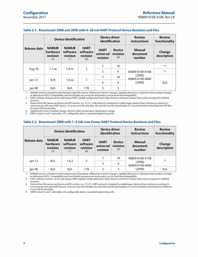
Table 2-1. Rosemount 2088 and 2090 with 4–20 mA HART Protocol Device Revisions and Files
Release date
Device identification Device driver identification
Review instructions
Review functionality
NAMUR hardware
revision(1)
1. NAMUR revision is located on the hardware tag of the device. Differences in level 3 changes, signified above by xx, represent minor product changes as defined per NE53. Compatibility and functionality are preserved and product can be used interchangeability.
NAMUR software revision
(1)
HART software revision
(2)
2. HART software revision can be read using a HART capable configuration tool. Value shown is minimum revision that could correspond to NAMUR revisions.
HART universal revision
Device revision
(3)
3. Device driver file names use Device and DD revision, e.g. 10_01. HAR protocol is designed to enable legacy device driver revisions to continue to communicate with new HART devices. To access new functionality, the new DD must be downloaded. It is recommended to download new DD files to ensure full functionality.
Manual document
number
Change description
Aug-16 1.1.xx 1.0.xx 37 10
00809-0100-4108 (2088)
00809-0100-4690 (2090)
(4)
4. Updated electronics hardware design. Intrinsic Safety temperature classification change.
5 9 (5)
5. HART revision 5 and 7 selectable, LOI, configurable alarms, expanded engineering units.
Jan-13 N/A 1.0.xx 17 10
N/A5 9
Jan-98 N/A N/A 178 5 3
Table 2-2. Rosemount 2088 with 1–5 Vdc Low Power HART Protocol Device Revisions and Files
Release date
Device identification Device driver identification
Review instructions
Review functionality
NAMUR hardware
revision(1)
1. NAMUR revision is located on the hardware tag of the device. Differences in level 3 changes, signified above by xx, represent minor product changes as defined per NE53. Compatibility and functionality are preserved and product can be used interchangeability.
NAMUR software revision
(1)
HART software revision
(2)
2. HART software revision can be read using a HART capable configuration tool. Value shown is minimum revision that could correspond to NAMUR revisions.
HART universal revision
Device revision
(3)
3. Device driver file names use Device and DD revision, e.g. 10_01. HART protocol is designed to enable legacy device driver revisions to continue to communicate with new HART devices. To access new functionality, the new DD must be downloaded. It is recommended to download new DDfiles to ensure full functionality.
Manual document
number
Change description
Jan-13 N/A 1.0.2 37 10 00809-0100-4108
(2088)00809-0100-4690
(2090)
(4)
4. HART revision 5 and 7 selectable, LOI, configurable alarms, expanded engineering units.
5 9
Jan-98 N/A N/A 178 5 3 N/A
4 Configuration

Reference Manual 00809-0100-4108, Rev CB
ConfigurationNovember 2017
2.3 HART installation flowchart
Figure 2-1. HART® Installation Flowchart
START HERE
Bench Calibration?
Field InstallNo
Set Units(page 13)
Set Range Points(page 13)
Select Linear Output
(page 13)
Set Damping(page 16)
Verify
Apply Pressure
Yes
WithinSpecifications? Yes
No
Refer toSection 5: Operation
and maintenance
Configure Security and
Alarm(page 43)
Mount Transmitter(page 31)
Wire Transmitter(page 47)
Power Transmitter(page 46)
Trim the Transmitter
(page 56)
Done
Review Transmitter Configuration
(page 9)
Confirm Transmitter Configuration
(page 11)
Configure for Pressure
Check Process Connection
(page 46)
5Configuration

Reference Manual00809-0100-4108, Rev CB
ConfigurationNovember 2017
2.4 Transmitter overviewThe Rosemount™ 2088, 2090F, and 2090P are offered for Gage Pressure (GP) and Absolute Pressure (AP) measurements. The Rosemount 2088 utilizes piezoresistive sensor technology for AP and GP measurements.
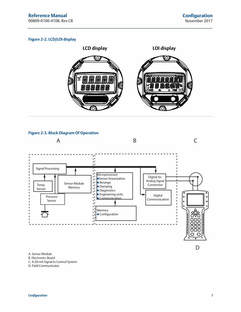
The major components of the Rosemount 2088, 2090F, and 2090P are the sensor module and the electronics housing. The sensor module contains the oil filled sensor system (isolating diaphragm, oil fill system, and sensor) and the sensor electronics. The sensor electronics are installed within the sensor module and include a temperature sensor, a memory module, and the analog to digital signal converter (A/D converter). The electrical signals from the sensor module are transmitted to the output electronics in the electronics housing. The electronics housing contains the output electronics board, the optional external configuration buttons, and the terminal block. The basic block diagram of the transmitter is illustrated in Figure 2-3 on page 7.
When pressure is applied to the isolating diaphragm, the oil deflects the sensor which then changes its capacitance or voltage signal. This signal is then changed to a digital signal by the Signal Processing. The microprocessor then takes the signals from the Signal Processing and calculates the correct output of the transmitter. This signal is then sent to the D/A converter, which converts the signal back to the analog signal, then superimposes the HART signal on the 4–20 mA (1–5 Vdc) output.
An optional LCD display can be ordered that connects directly to the interface board which maintains direct access to the signal terminals. The display indicates output and abbreviated diagnostic messages. A glass display cover is provided. For 4-20 mA HART output, the LCD display features a two-line display. The first line displays the actual measured value, the second line of six characters displays the engineering units. The LCD display can also display diagnostic messages.
NoteLCD display utilizes a 5 � 6 character display and can display output and diagnostic messages. The LOI display uses an 8 � 6 character display and can display output, diagnostic messages, and LOI menu screens. The LOI display comes with two buttons mounted on the front of the display board. See Figure 2-2.
6 Configuration
Reference Manual 00809-0100-4108, Rev CB
ConfigurationNovember 2017
Figure 2-2. LCD/LOI display
Figure 2-3. Block Diagram Of Operation
A. Sensor ModuleB. Electronics BoardC. 4-20 mA Signal to Control SystemD. Field Communicator
LCD display LOI display
A B C
D
Signal Processing
Temp. Sensor
Sensor Module Memory
MicroprocessorSensor linearization Rerange Damping Diagnostics Engineering units Communication
Memory Configuration
Digital-to-Analog Signal
Conversion
Digital Communication
Pressure Sensor
7Configuration
Reference Manual00809-0100-4108, Rev CB
ConfigurationNovember 2017
2.5 Configuration overviewThis section contains information on commissioning and tasks that should be performed on the bench prior to installation, as well as tasks performed after installation as described in “Performing transmitter tests” on page 23.
Field Communicator, AMS Device Manager, and Local Operator Interface (LOI) instructions are given to perform configuration functions. For convenience, Field Communicator Fast Key sequences are labeled “Fast Keys,” and abbreviated LOI menus are provided for each function below.
Full Field Communicator menu trees and Fast Key sequences are available in Appendix C: Field Communicator menu trees and Fast Keys. LOI menu trees are available in Appendix D: Local Operator Interface.
2.6 Configuration basics
The Rosemount 2088, 2090F, and 2090P can be configured either before or after installation. Configuring the transmitter on the bench using either a Field Communicator, AMS Device Manager, or LOI ensures all transmitter components are in working order prior to installation. Verify that the security switch is set in the unlock position ( ) in order to proceed with configuration. See Figure 4-2 on page 43 for switch location.
NoteLOI is available with the Rosemount 2088 (option M4) but is not available with the Rosemount 2090F or 2090P.
2.6.1 Configuring on the benchTo configure on the bench, required equipment includes a power supply, and a Field Communicator, AMS Device Manager, or an LOI (option M4). Wire equipment as shown in Figure 2-4 below. To ensure successful HART communication, a resistance of at least 250 Ωs must be present between the transmitter and the power supply, see “Power supply” on page 46 for details. Connect the Field Communicator leads to the terminals labeled “COMM” on the terminal block or 1–5 V configuration, wire as shown in Figure 2-4 on page 9. The Field Communicator is connected to the terminals labeled VOUT/COMM.
Set all transmitter hardware adjustments during commissioning to avoid exposing the transmitter electronics to the plant environment after installation.
8 Configuration

Reference Manual 00809-0100-4108, Rev CB
ConfigurationNovember 2017
Figure 2-4. Wiring the Transmitter (4–20 mA HART)
A. Vdc supplyB. R L≥ 250 (necessary for HART communication only)
2.6.2 Configuration tools
Figure 2-5. Wiring the Transmitter (1–5 Vdc Low Power)
A. DC power supplyB. Voltmeter
Configuring with a Field CommunicatorThere are two interfaces available with the Field Communicator: Traditional and Dashboard interfaces. All steps using a Field Communicator will be described using Dashboard interfaces. HART shows the Device Dashboard interface. As stated in System readiness , it is critical that the latest DD’s are loaded into the Field Communicator. Visit Emerson.com or FieldCommGroup.org to download latest DD library.
Field Communicator menu trees and Fast Keys are available in Appendix C: Field Communicator menu trees and Fast Keys.
A
B
A
B
9Configuration
Reference Manual00809-0100-4108, Rev CB
ConfigurationNovember 2017
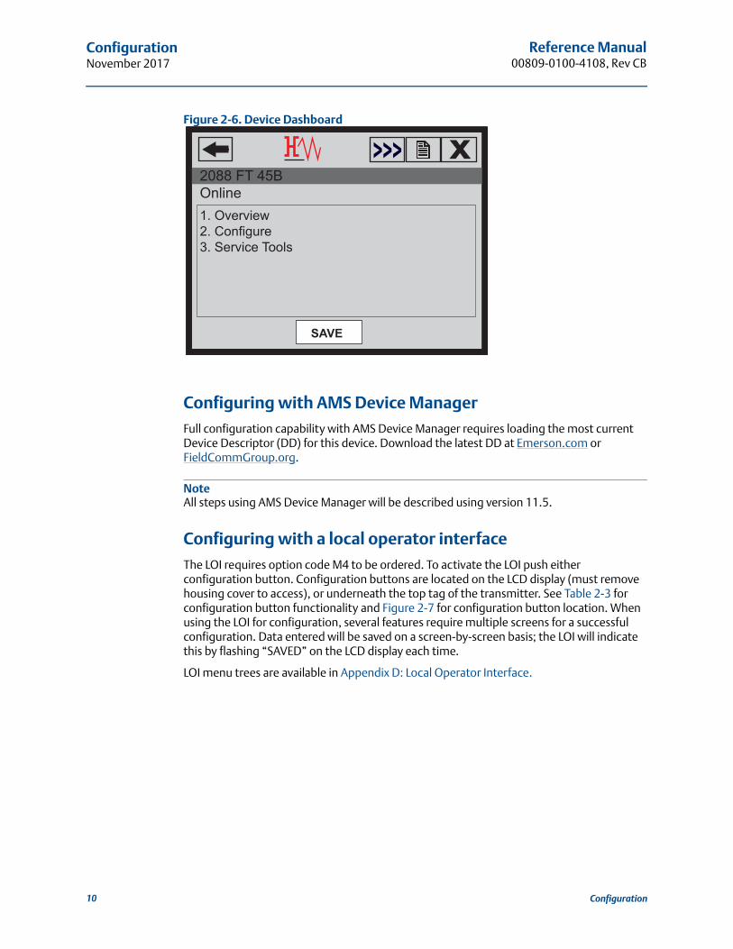
Figure 2-6. Device Dashboard
Configuring with AMS Device ManagerFull configuration capability with AMS Device Manager requires loading the most current Device Descriptor (DD) for this device. Download the latest DD at Emerson.com or FieldCommGroup.org.
NoteAll steps using AMS Device Manager will be described using version 11.5.
Configuring with a local operator interfaceThe LOI requires option code M4 to be ordered. To activate the LOI push either configuration button. Configuration buttons are located on the LCD display (must remove housing cover to access), or underneath the top tag of the transmitter. See Table 2-3 for configuration button functionality and Figure 2-7 for configuration button location. When using the LOI for configuration, several features require multiple screens for a successful configuration. Data entered will be saved on a screen-by-screen basis; the LOI will indicate this by flashing “SAVED” on the LCD display each time.
LOI menu trees are available in Appendix D: Local Operator Interface.
SAVE
1. Overview2. Configure3. Service Tools
2088 FT 45BOnline
10 Configuration
Reference Manual 00809-0100-4108, Rev CB
ConfigurationNovember 2017
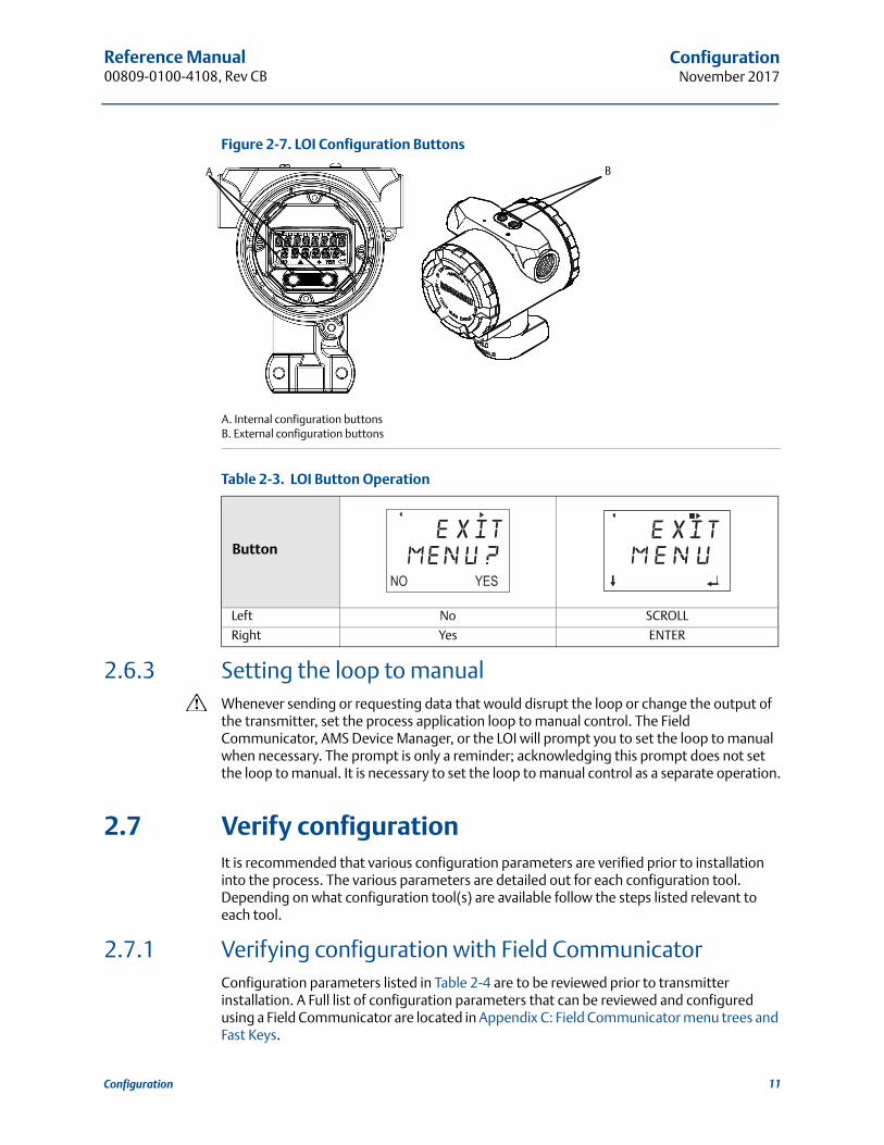
Figure 2-7. LOI Configuration Buttons
A. Internal configuration buttonsB. External configuration buttons
Table 2-3. LOI Button Operation
2.6.3 Setting the loop to manualWhenever sending or requesting data that would disrupt the loop or change the output of the transmitter, set the process application loop to manual control. The Field Communicator, AMS Device Manager, or the LOI will prompt you to set the loop to manual when necessary. The prompt is only a reminder; acknowledging this prompt does not set the loop to manual. It is necessary to set the loop to manual control as a separate operation.
2.7 Verify configurationIt is recommended that various configuration parameters are verified prior to installation into the process. The various parameters are detailed out for each configuration tool. Depending on what configuration tool(s) are available follow the steps listed relevant to each tool.
2.7.1 Verifying configuration with Field CommunicatorConfiguration parameters listed in Table 2-4 are to be reviewed prior to transmitter installation. A Full list of configuration parameters that can be reviewed and configured using a Field Communicator are located in Appendix C: Field Communicator menu trees and Fast Keys.
Button
Left No SCROLL
Right Yes ENTER
BA
11Configuration

Reference Manual00809-0100-4108, Rev CB
ConfigurationNovember 2017
Fast key sequences for the latest DD are shown in Table 2-4. For Fast Key sequences for legacy DD's contact your local Emerson Representative.
Table 2-4. Rosemount 2088 and 2090F/P device dashboard Fast Key sequence
2.7.2 Verifying configuration with AMS Device Manager Right select on the device and select Configuration Properties from the menu. Navigate the tabs to review the transmitter configuration data.
2.7.3 Verifying configuration with local operator interfacePress any configuration button to activate the LOI. Select VIEW CONFIG to review the below parameters. Use the configuration buttons to navigate through the menu. The parameters to be reviewed prior to installation include:
2.7.4 Verifying process variables configurationThis section describes how to verify that the correct process variables are selected.
Verifying process variables with a Field Communicator
Verifying process variables with AMS Device Manager
1. Right select the device and select Overview from the menu.
2. Select the All Variables button to display the primary, secondary, tertiary and quaternary variables.
2.8 Basic setup of the transmitterThis section goes through the necessary steps for basic setup of a pressure transmitter.
From the HOME screen, enter the Fast Key sequences listed
Function
Fast Key sequence
HART 7 HART 5
Alarm and Saturation Levels 2, 2, 2, 5 2, 2, 2, 5
Damping 2, 2, 1, 1, 5 2, 2, 1, 1, 5
Primary Variable 2, 1, 1, 4, 1 2, 1, 1, 4, 1
Range Values 2, 1, 1, 4 2, 1, 1, 4
Tag 2, 2, 7, 1, 1 2, 2, 7, 1, 1
Transfer Function 2, 2, 1, 1, 6 2, 2, 1, 1, 6
Units 2, 2, 1, 1, 4 2, 2, 1, 1, 4
Tag Primary Variable
Units Range Values
Transfer Function Damping
Alarm and Saturation Levels
From the HOME screen, enter the Fast Key sequence
Device Dashboard Fast Keys 3, 2, 1
12 Configuration

Reference Manual 00809-0100-4108, Rev CB
ConfigurationNovember 2017
2.8.1 Setting pressure unitsThe pressure unit command sets the unit of measure for the reported pressure.
Setting pressure units with a Field Communicator
Setting pressure units with AMS Device Manager 1. Right select the device and select Configure.
2. Select Manual Setup and select desired units from Pressure Units dropdown menu.
3. Select Send when complete.
Setting pressure units with a local operator interfaceFollow Figure 2-8 on page 13 to select desired pressure and temperature units. Use the SCROLL and ENTER buttons to select desired unit. Save by selecting SAVE as indicated on the LCD display screen.
Figure 2-8. Selecting Units with LOI
2.8.2 Rerange the transmitterThe range values command sets each of the lower and upper range analog values (4 and 20 mA/1–5 Vdc points) to a pressure. The lower range point represents 0% of range and the upper range point represents 100% of range. In practice, the transmitter range values may be changed as often as necessary to reflect changing process requirements. For a complete listing of Range & Sensor limits, refer to “Functional specifications” on page 74.
Select from one of the methods below to rerange the transmitter. Each method is unique; examine all options closely before deciding which method works best for your process.
Rerange by manually setting range points with a Field Communicator, AMS Device Manager, or LOI.
Rerange with a pressure input source and a Field Communicator, AMS Device Manager, LOI, or local zero and span buttons.
From the HOME screen, enter the Fast Key sequence
Device Dashboard Fast Keys 2, 2, 1, 1, 4
UNITSPRESS UNITSPRESS UNITSTEMP UNITSBACK TO MENUEXIT MENU
PRESS UNITSINH2OMMHGCMHG0CMHG0CPSIPSFATMTORRPAKPA...
VIEW CONFIGZERO TRIMUNITSUNITSRERANGELOOP TESTDISPLAYEXTENDED MENUEXIT MENU
13Configuration
Reference Manual00809-0100-4108, Rev CB
ConfigurationNovember 2017
Manually rerange the transmitter by entering range points
Entering range points with a Field Communicator
Entering range points with AMS Device Manager
1. Right select the device and select Configure.
2. Select Manual Setup and select Analog Output.
3. Enter upper and lower range values in the Range Limits box and click Send.
4. Carefully read the warning and click Yes if it is safe to apply the changes.
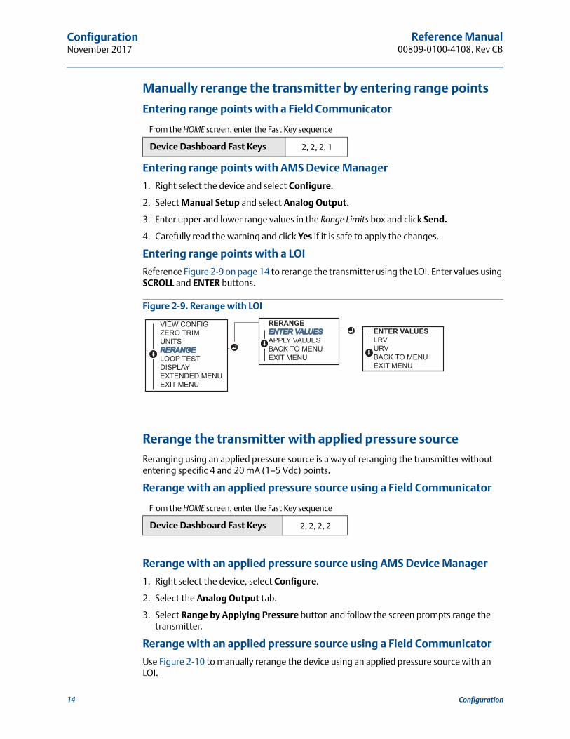
Entering range points with a LOI
Reference Figure 2-9 on page 14 to rerange the transmitter using the LOI. Enter values using SCROLL and ENTER buttons.
Figure 2-9. Rerange with LOI
Rerange the transmitter with applied pressure sourceReranging using an applied pressure source is a way of reranging the transmitter without entering specific 4 and 20 mA (1–5 Vdc) points.
Rerange with an applied pressure source using a Field Communicator
Rerange with an applied pressure source using AMS Device Manager
1. Right select the device, select Configure.
2. Select the Analog Output tab.
3. Select Range by Applying Pressure button and follow the screen prompts range the transmitter.
Rerange with an applied pressure source using a Field Communicator
Use Figure 2-10 to manually rerange the device using an applied pressure source with an LOI.
From the HOME screen, enter the Fast Key sequence
Device Dashboard Fast Keys 2, 2, 2, 1
From the HOME screen, enter the Fast Key sequence
Device Dashboard Fast Keys 2, 2, 2, 2
RERANGEENTER VALUESENTER VALUESAPPLY VALUESBACK TO MENUEXIT MENU
ENTER VALUESLRVURVBACK TO MENUEXIT MENU
VIEW CONFIGZERO TRIMUNITSRERANGERERANGELOOP TESTDISPLAYEXTENDED MENUEXIT MENU
14 Configuration

Reference Manual 00809-0100-4108, Rev CB
ConfigurationNovember 2017
Figure 2-10. Rerange with Applied Pressure Using LOI
Rerange with an applied pressure source using local zero and span buttons
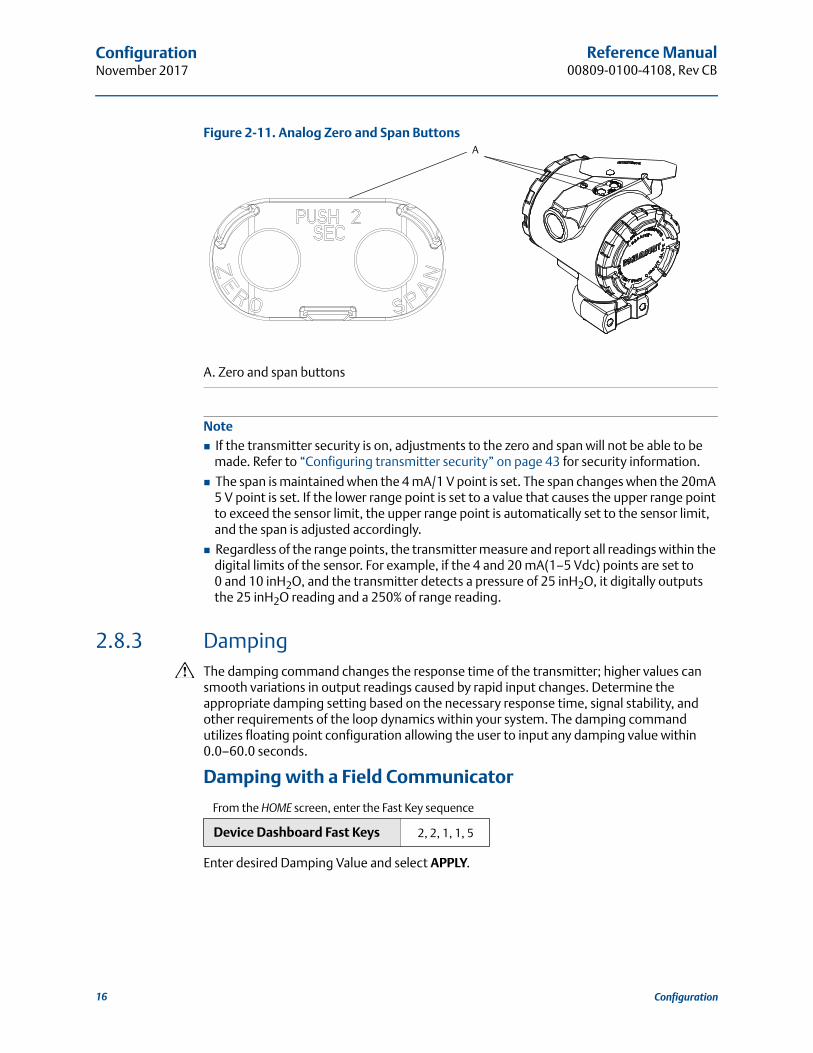
If ordered, local zero and span buttons (option code D4) can be used to rerange the transmitter with an applied pressure. Refer to Figure 2-11 on page 16 for analog zero and span button location.
To rerange the transmitter using the span and zero buttons, perform the following procedure:
1. Loosen the screw holding the top tag of the transmitter housing. Rotate the label to expose the zero and span buttons.
2. Confirm device has local zero and span buttons by verifying blue retainer under the tag.
3. Apply transmitter pressure.
4. Rerange the transmitter.
a. To change the zero (4 mA/1 V point) while maintaining the span: press and hold zero button for at least two seconds then release.
b. To change the span (20 mA/5 V point) while maintaining the zero point: press and hold the span button for at least two seconds and then release.
Note4 mA and 20 mA points must maintain the minimum span defined in Appendix A: Specifications and reference data.
RERANGEENTER VALUESAPPLY VALUESAPPLY VALUESBACK TO MENUEXIT MENU
APPLY VALUESLRVURVBACK TO MENUEXIT MENU
VIEW CONFIGZERO TRIMUNITSRERANGERERANGELOOP TESTDISPLAYEXTENDED MENUEXIT MENU
15Configuration
Reference Manual00809-0100-4108, Rev CB
ConfigurationNovember 2017
Figure 2-11. Analog Zero and Span Buttons
A. Zero and span buttons
Note If the transmitter security is on, adjustments to the zero and span will not be able to be
made. Refer to “Configuring transmitter security” on page 43 for security information.
The span is maintained when the 4 mA/1 V point is set. The span changes when the 20mA 5 V point is set. If the lower range point is set to a value that causes the upper range point to exceed the sensor limit, the upper range point is automatically set to the sensor limit, and the span is adjusted accordingly.
Regardless of the range points, the transmitter measure and report all readings within the digital limits of the sensor. For example, if the 4 and 20 mA(1–5 Vdc) points are set to 0 and 10 inH2O, and the transmitter detects a pressure of 25 inH2O, it digitally outputs the 25 inH2O reading and a 250% of range reading.
2.8.3 DampingThe damping command changes the response time of the transmitter; higher values can smooth variations in output readings caused by rapid input changes. Determine the appropriate damping setting based on the necessary response time, signal stability, and other requirements of the loop dynamics within your system. The damping command utilizes floating point configuration allowing the user to input any damping value within 0.0–60.0 seconds.
Damping with a Field Communicator
Enter desired Damping Value and select APPLY.
From the HOME screen, enter the Fast Key sequence
Device Dashboard Fast Keys 2, 2, 1, 1, 5
A
16 Configuration

Reference Manual 00809-0100-4108, Rev CB
ConfigurationNovember 2017
Damping with AMS Device Manager1. Right select the device and select Configure.
2. Select Manual Setup.
3. Within the Pressure Setup box, enter desired damping value and click Send.
4. Carefully read the warning and click Yes if it is safe to apply the changes.
Damping with a LOIReference Figure 2-12 to enter damping values using an LOI.
Figure 2-12. Damping with LOI
2.9 Configuring the LCD displayThe LCD display configuration command allows customization of the LCD display to suit application requirements. The LCD display will alternate between the selected items.
In the following instructions, the LCD display can also be configured to display configuration information during the device startup. Select Review Parameters at Startup to enable or disable this functionality.
Reference Figure 2-2 on page 7 LCD display with LOI for image of LCD display screen.
Configuring LCD display with a Field Communicator
Configuring LCD display with AMS Device Manager1. Right select on the device and select Configure.
2. Select Manual Setup, select the Display tab.
3. Select desired display options and click Send.
Pressure Units Sensor Temperature
% of Range mA/Vdc Output
Scaled Variable
From the HOME screen, enter the Fast Key sequence
Device Dashboard Fast Keys 2, 2, 4
EXTENDED MENUCALIBRATDAMPINGDAMPINGTRANSFER FUNCTSCALED VARIABASSIGN PVTAGALARM SAT VALUESPASSWORDSIMLATEHART REVBACK TO MENUEXIT MENU
VIEW CONFIGZERO TRIMUNITSRERANGELOOP TESTDISPLAYEXTENDED MENUEXTENDED MENUEXIT MENU
17Configuration

Reference Manual00809-0100-4108, Rev CB
ConfigurationNovember 2017
Configuring LCD display with a local operator interfaceRefer to Figure 2-13 for LCD display configuration using a LOI.
Figure 2-13. Display with LOI
2.10 Detailed transmitter setup
2.10.1 Configuring alarm and saturation levelsIn normal operation, the transmitter will drive the output in response to pressure from the lower to upper saturation points. If the pressure goes outside the sensor limits, or if the output would be beyond the saturation points, the output will be limited to the associated saturation point.
The transmitter automatically and continuously performs self-diagnostic routines. If the self-diagnostic routines detect a failure, the transmitter drives the output to configured alarm and value based on the position of the alarm switch. See “Setting transmitter alarm” on page 45.
Table 2-5. Rosemount Alarm and Saturation Values
Table 2-6. NAMUR-Compliant Alarm and Saturation Values
Table 2-7. Custom Alarm and Saturation Values
Level 4–20 mA (1–5 Vdc) saturation 4–20 mA (1–5 Vdc alarm
Low 3.90 mA (0.97 V) ≤ 3.75 mA (0.95 V)
High 20.80 mA (5.20 V) ≥ 21.75 mA (5.40 V)
Level 4–20 mA (1–5 Vdc) saturation 4–20 mA (1–5 Vdc) alarm
Low 3.80 mA (0.95 V) ≤ 3.60 mA (0.90 V) (.90 –.95 V)
High 20.50 mA (5.13 V) ≥22.50 mA (5.63 V) (5.05 –5.75 V)
Level 4–20 mA (1–5 Vdc) saturation 4–20 mA (1–5 Vdc) alarm
Low 3.70 mA– 3.90 mA (.90 –.95 V) 3.60–3.80 mA (.90 –.95 V)
High 20.10 mA –22.90 mA (5.025 –5.725 V) 20.20 mA – 23.00 mA (5.05 –5.75 V)
DISPLAYPRESS (on/off)SCALED (on/off)TEMP (on/off)%RANGE (on/off)ANALOG (on/off)STRTUP (on/off)BACK TO MENUEXIT MENU
VIEW CONFIGZERO TRIMUNITSRERANGELOOP TESTDISPLAYDISPLAYEXTENDED MENUEXIT MENU
18 Configuration

Reference Manual 00809-0100-4108, Rev CB
ConfigurationNovember 2017
Failure mode alarm and saturation levels can be configured using a Field Communicator, AMS Device Manager, and the LOI. The following limitations exist for custom levels:
Low alarm level must be less than the low saturation level
High alarm level must be higher than the high saturation level
Alarm and saturation levels must be separated by at least 0.1 mA (0.025 Vdc)
The configuration tool will provide an error message if the configuration rule is violated.
NoteTransmitters set to HART multidrop mode send all saturation and alarm information digitally; saturation and alarm conditions will not affect the analog output. See also “Establishing multidrop communication” on page 25.
Configuring alarm and saturation levels using a Field Communicator
Configuring alarm and saturation levels with AMS Device Manager1. Right select on the device, and select Configure.
2. Select Configure Alarm and Saturation Levels button.
3. Follow screen prompts to configure Alarm and Saturation Levels.
Configuring alarm and saturation levels using LOIRefer to Figure 2-14 for instructions to configure alarm and saturation levels.
Figure 2-14. Configuring Alarm and Saturation with LOI
From the HOME screen, enter the Fast Key sequence
Device Dashboard Fast Keys 2, 2, 2, 5
EXTENDED MENUCALIBRATDAMPINGTRANSFER FUNCTSCALED VARIABASSIGN PVTAGALARM SAT VALUESALARM SAT VALUESPASSWORDSIMULATEHART REVBACK TO MENUEXIT MENU
ALARM SAT VALUESROSEMOUNT VALUESNAMUR VALUESOTHER VALUESBACK TO MENUEXIT MENU
VIEW CONFIGZERO TRIMUNITSRERANGELOOP TESTDISPLAYEXTENDED MENUEXTENDED MENUEXIT MENU
19Configuration

Reference Manual00809-0100-4108, Rev CB
ConfigurationNovember 2017
2.10.2 Configuring scaled variableThe Scaled Variable configuration allows the user to create a relationship/conversion between the pressure units and user-defined/custom units. There are two use cases for Scaled Variable. The first use case is to allow custom units to be displayed on the transmitter's LCD/LOI Display. The second use case is to allow custom units to drive the transmitter's 4–20 mA (1–5 Vdc) output.
If the user desires custom units to drive the 4–20 mA (1–5 Vdc) output, Scaled Variable must be re-mapped as the primary variable. Refer to “Re-mapping device variables” on page 21.
The Scaled Variable configuration defines the following items:
Scaled Variable units - Custom units to be displayed.
Scaled data options - Defines the transfer function for the application
Pressure value position 1 - Lower known value point with consideration of linear offset.
Scaled Variable value position 1 - Custom unit equivalent to the lower known value point.
Pressure value position 2 - Upper known value point
Scaled Variable value position 2 - Custom unit equivalent to the upper known value point
Linear offset - The value required to zero out pressures effecting the desired pressure reading.
20 Configuration

Reference Manual 00809-0100-4108, Rev CB
ConfigurationNovember 2017
Configuring scaled variable using a Field Communicator
1. Follow the screen prompts to configure Scaled Variable.
a. Select Linear under Select Scaled data options.
Configuring scaled variable using AMS Device Manager1. Right select on the device and, select Configure.
2. Select the Scaled Variable tab and select the Scaled Variable button.
3. Follow screen prompts to configure Scaled Variable
a. Select Linear under Select Scaled data options.
Configuring scaled variable using a LOI Refer to Figure 2-15 on page 21 for instructions to configure Scaled Variable using a LOI.
Figure 2-15. Configuring Scaled Variable Using a LOI
2.10.3 Re-mapping device variablesThe re-mapping function allows the transmitter primary, secondary, tertiary, and quaternary variables (PV, 2V, 3V, and 4V) to be configured as desired. The PV can be remapped with a Field Communicator, AMS Device Manager, or a LOI. Variables (2V, 3V, and 4V) can only be re-mapped via Field Communicator or AMS Device Manager.
NoteThe variable assigned to the primary variable drives the 4–20 mA (1–5 Vdc) output. This value can be selected as Pressure or Scaled Variable. The 2, 3, and 4 variables only apply if HART burst mode is being used.
From the HOME screen, enter the Fast Key sequence
Device Dashboard Fast Keys 2, 1, 4, 7
EXTENDED MENUCALIBRATDAMPINGTRANSFER FUNCTSCALED VARIABSCALED VARIABASSIGN PVTAGALARM SAT VALUESPASSWORDSIMLATEHART REVBACK TO MENUEXIT MENU
SCALED VARIABVIEW SCALEDCONFIG SCALEDCONFIG SCALEDBACK TO MENUEXIT MENU
VIEW CONFIGZERO TRIMUNITSRERANGELOOP TESTDISPLAYEXTENDED MENUEXTENDED MENUEXIT MENU
21Configuration
Reference Manual00809-0100-4108, Rev CB
ConfigurationNovember 2017
Re-mapping using a Field Communicator
Re-mapping using AMS Device Manager1. Right select the device and select Configure.
2. Select Manual Setup and click on the HART tab.
3. Assign Primary, secondary, tertiary, and quaternary variables under Variable Mapping.
4. Select Send.
5. Carefully read the warning and select Yes if it is safe to apply the changes.
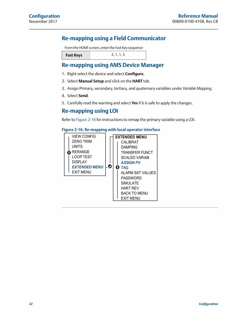
Re-mapping using LOIRefer to Figure 2-16 for instructions to remap the primary variable using a LOI.
Figure 2-16. Re-mapping with local operator interface
From the HOME screen, enter the Fast Key sequence
Fast Keys 2, 1, 1, 3
VIEW CONFIGZERO TRIMUNITSRERANGELOOP TESTDISPLAYEXTENDED MENUEXIT MENU
EXTENDED MENUCALIBRATDAMPINGTRANSFER FUNCTSCALED VARIABASSIGN PVTAGALARM SAT VALUESPASSWORDSIMULATEHART REVBACK TO MENUEXIT MENU
22 Configuration
Reference Manual 00809-0100-4108, Rev CB
ConfigurationNovember 2017
2.11 Performing transmitter tests
2.11.1 Verifying alarm levelIf the transmitter is repaired or replaced, verify the transmitter alarm level before returning the transmitter to service. This is useful in testing the reaction of the control system to a transmitter in an alarm state. Thus ensuring the control system recognizes the alarm when activated. To verify the transmitter alarm values, perform a loop test and set the transmitter output to the alarm value (see Table 2-5, 2-6, and 2-7 on page 18).
NoteBefore returning transmitter to service, verify security switch is set to the correct position. Refer to “Verify configuration” on page 11.
2.11.2 Performing an analog loop testThe analog loop test command verifies the output of the transmitter, the integrity of the loop, and the operations of any recorders or similar devices installed in the loop. It is recommended that the 4–20 mA (1–5 Vdc) points in addition to alarm levels when installing, repairing, or replacing a transmitter.
The host system may provide a current measurement for the 4–20 mA (1–5 Vdc) HART output. If not, connect a reference meter to the transmitter by either connecting the meter to the test terminals on the terminal block, or shunting transmitter power through the meter at some point in the loop. For 1–5 V output, voltage measurement is directly measured from Vout to (–) terminals.
Performing an analog loop test using a Field Communicator
Performing an analog loop test using AMS Device Manager1. Right select on the device and, within the Methods drop down menu, move cursor over
Diagnostics and Test. In the Diagnostics and Test drop down menu select Loop Test.
2. Select Next after setting the control loop to manual.
3. Follow Screen prompts to perform a Loop Test.
4. Select Finish to acknowledge the method is complete.
Performing analog loop test using a LOITo perform an analog loop test using the LOI, the 4 mA (1 V), 20 mA (5 V), and custom mA point may be set manually. Reference Figure 2-17 for instructions on how to perform a transmitter loop test using an LOI.
From the HOME screen, enter the Fast Key sequence
Device Dashboard Fast Keys 3, 5, 1
23Configuration

Reference Manual00809-0100-4108, Rev CB
ConfigurationNovember 2017
Figure 2-17. Performing an Analog Loop Test Using an LOI
2.11.3 Simulate device variablesIt is possible to temporarily set the Pressure, Sensor Temperature, or Scaled Variable to a user-defined fixed value for testing purposes. Once the simulated variable method is left, the process variable will be automatically returned to a live measurement. Simulate device variables is only available in HART Revision 7 mode.
Simulate digital signal with a Field Communicator
Simulate digital signal with AMS Device Manager1. Right select on the device and select Service Tools.
2. Select Simulate.
3. Under Device Variables select a digital value to simulate.
a. Pressureb. Sensor Temperaturec. Scaled Variable
4. Follow the screen prompts to simulate selected digital value.
2.12 Configuring burst modeBurst mode is compatible with the analog signal. Because the HART protocol features simultaneous digital and analog data transmission, the analog value can drive other equipment in the loop while the control system is receiving the digital information. Burst mode applies only to the transmission of dynamic data (pressure and temperature in engineering units, pressure in percent of range, Scaled Variable, and/or analog output), and does not affect the way other transmitter data is accessed. However, when activated, bust mode can slow down communication of non-dynamic data to the host by 50 percent.
Access to information other than dynamic transmitter data is obtained through the normal poll/response method of HART communication. A Field Communicator, AMS Device Manager, or the control system may request any of the information that is normally available while the transmitter is in burst mode. Between each message sent by the transmitter, a short pause allows the Field Communicator, AMS Device Manager, or a control system to initiate a request.
From the HOME screen, enter the Fast Key sequence
Device Dashboard Fast Keys 3, 5
LOOP TESTSET 4MASET 20MASET CUSTOMEND LOOP TESTBACK TO MENUEXIT MENU
VIEW CONFIGZERO TRIMUNITSRERANGELOOP TESTLOOP TESTDISPLAYEXTENDED MENUEXIT MENU
(1V)(5V)
24 Configuration

Reference Manual 00809-0100-4108, Rev CB
ConfigurationNovember 2017
Choosing burst mode options in HART 5
Message content options:
PV only
Percent of Range
PV, 2V, 3V, 4V
Process Variables
Device Status
Choosing burst mode options in HART 7
Message content options:
PV only
Percent of Range
PV, 2V, 3V, 4V
Process Variables and Status
Process Variables
Device Status
Choosing a HART 7 trigger mode
When in HART 7 mode, the following trigger modes can be selected.
Continuous (same as HART5 burst mode)
Rising
Falling
Windowed
On Change
NoteConsult your host system manufacturer for burst mode requirements.
Configuring burst mode using a Field Communicator
Configuring burst mode using AMS Device Manager1. Right select on the device and select Configure.
2. Select the HART tab.
3. Enter the configuration in Burst Mode Configuration fields.
2.13 Establishing multidrop communicationMultidropping transmitters refers to the connection of several transmitters to a single communications transmission line. Communication between the host and the transmitters takes place digitally with the analog output of the transmitters deactivated.
From the HOME screen, enter the Fast Key sequence
Device Dashboard Fast Keys 2, 2, 5, 3
25Configuration

Reference Manual00809-0100-4108, Rev CB
ConfigurationNovember 2017
Multidrop installation requires consideration of the update rate necessary from each transmitter, the combination of transmitter models, and the length of the transmission line. Communication with transmitters can be accomplished with HART modems and a host implementing HART protocol. Each transmitter is identified by a unique address and responds to the commands defined in the HART protocol. Field Communicators and AMS Device Manager can test, configure, and format a multidropped transmitter the same way as a transmitter in a standard point-to-point installation.
Figure 2-18 shows a typical multidrop network. This figure is not intended as an installation diagram.
Figure 2-18. Typical Multidrop Network (4–20 mA only)
A. HART modemB. Power supply
The Rosemount 2088, 2090F, 2090P is set to address zero (0) at the factory, which allows operation in the standard point-to-point manner with a 4–20 mA (1–5 Vdc) output signal. To activate multidrop communication, the transmitter address must be changed to a number from 1 to 15 for HART Revision 5, or 1–63 for HART Revision 7. This change deactivates the 4–20 mA (1–5 Vdc) analog output, sending it to 4 mA (1 Vdc). It also disables the failure mode alarm signal, which is controlled by the upscale/downscale switch position. Failure signals in multidropped transmitters are communicated through HART messages.
2.13.1 Changing a transmitter addressTo activate multidrop communication, the transmitter poll address must be assigned a number from 1 to 15 for HART Revision 5, and 1–63 for HART Revision 7. Each transmitter in a multidropped loop must have a unique poll address.
A
B
26 Configuration
Reference Manual 00809-0100-4108, Rev CB
ConfigurationNovember 2017
Changing transmitter address using a Field Communicator
Changing transmitter address using AMS Device Manager1. Right select on the device and select Configure.
2. In HART Revision 5 mode:
a. Select Manual Setup, select the HART tab.b. In the Communication Settings box enter polling address in the Polling Address
box, select Send.
3. In HART Revision 7 mode:
a. Select Manual Setup, select the HART tab and select the Change Polling Address button.
4. Carefully read the warning and click Yes if it is safe to apply the changes.
2.13.2 Communicating with a multidropped transmitterTo communicate with a multidrop transmitter, the Field Communicator or AMS Device Manager has to be set up for Polling.
Communicating with a multidropped transmitter using a Field Communicator1. Select Utility and Configure HART Application.
2. Select Polling Addresses.
3. Enter 0–63.
Communicating with a multidropped transmitter using AMS Device Manager1. Select on the HART modem icon and select Scan All Devices.
From the HOME screen, enter the Fast Key sequence HART Revision 5 HART Revision 7
Device Dashboard Fast Keys 2, 2, 5, 2, 1 2, 2, 5, 2, 2
27Configuration

Reference Manual00809-0100-4108, Rev CB
ConfigurationNovember 2017
28 Configuration

Reference Manual 00809-0100-4108, Rev CB
Hardware InstallationNovember 2017
Section 3 Hardware installation
Overview . . . . . . . . . . . . . . . . . . . . . . . . . . . . . . . . . . . . . . . . . . . . . . . . . . . . . . . . . . . . . . . . page 29Safety messages . . . . . . . . . . . . . . . . . . . . . . . . . . . . . . . . . . . . . . . . . . . . . . . . . . . . . . . . . . page 29Considerations . . . . . . . . . . . . . . . . . . . . . . . . . . . . . . . . . . . . . . . . . . . . . . . . . . . . . . . . . . . page 30Installation procedures . . . . . . . . . . . . . . . . . . . . . . . . . . . . . . . . . . . . . . . . . . . . . . . . . . . . page 31Rosemount 306 Manifold . . . . . . . . . . . . . . . . . . . . . . . . . . . . . . . . . . . . . . . . . . . . . . . . . . page 40
3.1 OverviewThe information in this section covers installation considerations for the Rosemount™ 2088, 2090F, and 2090P, 2090F, and 2090P with HART® protocols. A Quick Start Guide is shipped with every transmitter to describe recommended pipe-fitting and wiring procedures for initial installation. Dimensional drawings for each transmitter variation and mounting configuration are included on page 31.
NoteFor transmitter disassembly and reassembly refer to “Disassembly procedures” on page 70, and “Reassembly procedures” on page 72.
3.2 Safety messagesProcedures and instructions in this section may require special precautions to ensure the safety of the personnel performing the operation. Information that raises potential safety
issues is indicated by a warning symbol ( ). Refer to the following safety messages before performing an operation preceded by this symbol.
29 Hardware Installation

Reference Manual00809-0100-4108, Rev CB
Hardware InstallationNovember 2017
3.3 Considerations
3.3.1 Installation considerationsMeasurement accuracy depends upon proper installation of the transmitter and impulse piping. Mount the transmitter close to the process and use a minimum of piping to achieve best accuracy. Keep in mind the need for easy access, personnel safety, practical field calibration, and a suitable transmitter environment. Install the transmitter to minimize vibration, shock, and temperature fluctuation.
ImportantInstall the enclosed pipe plug (found in the box) in unused housing conduit opening with a minimum of five threads of engagement to comply with explosion-proof requirements.
Explosions could result in death or serious injury.
Installation of this transmitter in an explosive environment must be in accordance with the appropriate local, national, and international standards, codes, and practices. Review the approvals section of the Rosemount 2088, 2090F, 2090P reference manual for any restrictions associated with a safe installation. Before connecting a Field Communicator in an explosive atmosphere, ensure the
instruments in the loop are installed in accordance with intrinsically safe or non-incendive field wiring practices.
In an explosion-proof/flameproof installation, do not remove the transmitter covers when power is applied to the unit.
Process leaks may cause harm or result in death.
Install and tighten process connectors before applying pressure.Electrical shock can result in death or serious injury.
Avoid contact with the leads and terminals. High voltage that may be present on leads can cause electrical shock.
Avoid contact with the leads and terminals.
Process leaks could result in death or serious injury.
Install and tighten all four flange bolts before applying pressure.
Do not attempt to loosen or remove flange bolts while the transmitter is in service.Replacement equipment or spare parts not approved by Emerson™ for use as spare parts could reduce the pressure retaining capabilities of the transmitter and may render the instrument dangerous.
Use only bolts supplied or sold by Emerson as spare parts.Improper assembly of manifolds to traditional flange can damage sensor module.
For safe assembly of manifold to traditional flange, bolts must break back plane of flange web (i.e., bolt hole) but must not contact sensor module housing.
30 Hardware Installation

Reference Manual 00809-0100-4108, Rev CB
Hardware InstallationNovember 2017
3.3.2 Environmental considerationsBest practice is to mount the transmitter in an environment that has minimal ambient temperature change. The transmitter electronics temperature operating limits are –40 to 185 °F (–40 to 85 °C). Refer to Appendix A: Reference data that lists the sensing element operating limits. Mount the transmitter so that it is not susceptible to vibration and mechanical shock and does not have external contact with corrosive materials.
3.3.3 Mechanical considerations
Steam serviceFor steam service or for applications with process temperatures greater than the limits of the transmitter, do not blow down impulse piping through the transmitter. Flush lines with the blocking valves closed and refill lines with water before resuming measurement. Refer to Figure 3-4 on page 35 through Figure 3-6 on page 36 for correct mounting orientation.
3.4 Installation procedures
3.4.1 Mount the transmitterThe following are approximate weights of each transmitter:
Rosemount 2088 2.44 lb (1,11 kg)
Rosemount 2090F 2.74 lb (1.24 kg)
Rosemount 2090P 2.96 lb (1.34 kg).
In many cases its compact size and light weight makes it possible to mount directly to the respective apparatus without using an additional mounting bracket. When this is not desirable, mount directly to a wall, panel, or two-inch pipe using the optional mounting bracket (see Figure 3-1 on page 32).
For dimensional drawing information refer to Appendix A: Reference data.
NoteMost transmitters are calibrated in the upright position. Mounting the transmitter in any other position will shift the zero point to the equivalent amount of liquid head pressure caused by the varied mounting position. To reset zero point, refer to “Sensor trim overview” on page 56.
Electronics housing clearanceMount the transmitter so the terminal side is accessible. Clearance of 0.75-in. (19 mm) is required for cover removal. Use a conduit plug in the unused conduit opening. Three inches of clearance is required for cover removal if a meter is installed.
Environmental seal for housingThread sealing (PTFE) tape or paste on male threads of conduit is required to provide a water/dust tight conduit seal and meets requirements of NEMA® Type 4X, IP66, and IP68. Consult factory if other Ingress Protection ratings are required.
31 Hardware Installation
Reference Manual00809-0100-4108, Rev CB
Hardware InstallationNovember 2017
)
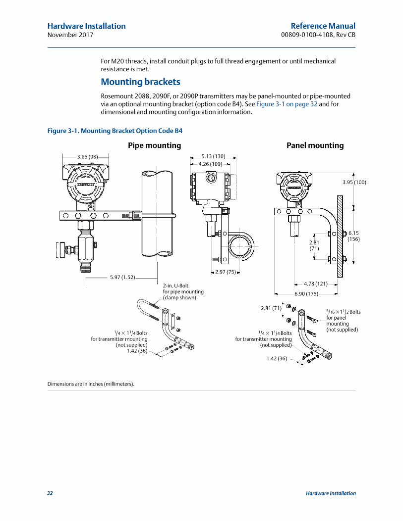
For M20 threads, install conduit plugs to full thread engagement or until mechanical resistance is met.
Mounting bracketsRosemount 2088, 2090F, or 2090P transmitters may be panel-mounted or pipe-mounted via an optional mounting bracket (option code B4). See Figure 3-1 on page 32 and for dimensional and mounting configuration information.
Figure 3-1. Mounting Bracket Option Code B4
Dimensions are in inches (millimeters).
Pipe mounting Panel mounting
5.97 (1.52)2.97 (75)
3.95 (100
6.15 (156)
2.81 (71)
4.78 (121)
6.90 (175)
2-in. U-Boltfor pipe mounting(clamp shown)
1.42 (36)
2.81 (71) 5/16 �11/2 Boltsfor panel mounting(not supplied)1/4 � 11/4 Bolts
for transmitter mounting(not supplied)
3.85 (98) 5.13 (130)
4.26 (109)
1/4 � 11/4 Boltsfor transmitter mounting
(not supplied)1.42 (36)
32 Hardware Installation

Reference Manual 00809-0100-4108, Rev CB
Hardware InstallationNovember 2017
Figure 3-2. Mounting Bracket Option Code B4
Dimensions are in inches (millimeters).
Pipe mounting Panel mounting
2-in. U-Bolt for pipe mounting(clamp shown)
¼ × 1¼ Bolt for transmitter mounting
(not supplies) 1.42 (36)
5.97 (152)
¼ × 1¼ Bolt for transmitter mounting
(not supplies) 1.42 (36)
× 1½ Bolt for panel mounting(not supplies)
5 ⁄16
2.97(75)
8.090(205.5)
4.78(121)
2.81071.4
33 Hardware Installation

Reference Manual00809-0100-4108, Rev CB
Hardware InstallationNovember 2017
Figure 3-3. Mounting Bracket Option Code B4
Dimensions are in inches (millimeters).
Pipe mounting Panel mounting
2-in. U-Bolt for pipe mounting(clamp shown)
¼ × 1¼ Bolt for transmitter mounting
(not supplies) 1.42 (36)
5.97 (152) 2.97(75) 4.78
(121)
¼ × 1¼ Bolt for transmitter mounting
(not supplies) 1.42 (36)
× 1½ Bolt for panel mounting(not supplies)
5 ⁄16
34 Hardware Installation
Reference Manual 00809-0100-4108, Rev CB
Hardware InstallationNovember 2017
3.4.2 Impulse piping
Mounting requirementsImpulse piping configurations depend on specific measurement conditions. Refer to Figure 3-4 on page 35 through Figure 3-6 on page 36 for examples of the following mounting con-figurations:
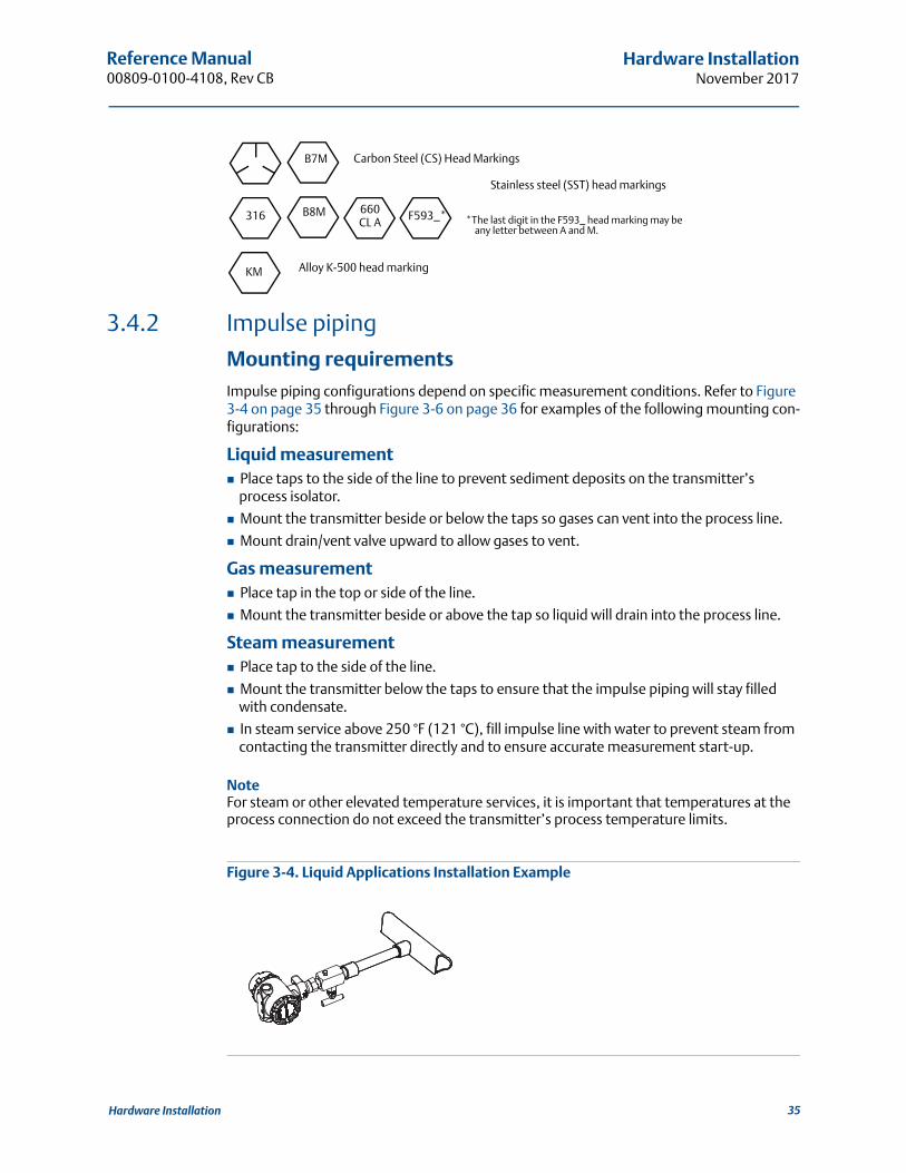
Liquid measurement Place taps to the side of the line to prevent sediment deposits on the transmitter’s
process isolator.
Mount the transmitter beside or below the taps so gases can vent into the process line.
Mount drain/vent valve upward to allow gases to vent.
Gas measurement Place tap in the top or side of the line.
Mount the transmitter beside or above the tap so liquid will drain into the process line.
Steam measurement Place tap to the side of the line.
Mount the transmitter below the taps to ensure that the impulse piping will stay filled with condensate.
In steam service above 250 °F (121 °C), fill impulse line with water to prevent steam from contacting the transmitter directly and to ensure accurate measurement start-up.
NoteFor steam or other elevated temperature services, it is important that temperatures at the process connection do not exceed the transmitter’s process temperature limits.
Figure 3-4. Liquid Applications Installation Example
Carbon Steel (CS) Head MarkingsB7M
316 B8M F593_*
Stainless steel (SST) head markings
KM
660 CL A
Alloy K-500 head marking
*The last digit in the F593_ head marking may be any letter between A and M.
35 Hardware Installation
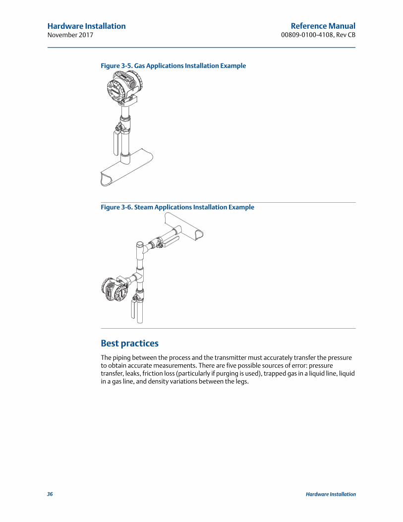
Reference Manual00809-0100-4108, Rev CB
Hardware InstallationNovember 2017
Figure 3-5. Gas Applications Installation Example
Figure 3-6. Steam Applications Installation Example
Best practicesThe piping between the process and the transmitter must accurately transfer the pressure to obtain accurate measurements. There are five possible sources of error: pressure transfer, leaks, friction loss (particularly if purging is used), trapped gas in a liquid line, liquid in a gas line, and density variations between the legs.
36 Hardware Installation

Reference Manual 00809-0100-4108, Rev CB
Hardware InstallationNovember 2017
The best location for the transmitter in relation to the process pipe is dependent on the process. Use the following guidelines to determine transmitter location and placement of impulse piping:
Keep impulse piping as short as possible.
For liquid service, slope the impulse piping at least 1 in./ft (8 cm/m) upward from the transmitter toward the process connection.
For gas service, slope the impulse piping at least 1 in./ft (8 cm/m) downward from the transmitter toward the process connection.
Avoid high points in liquid lines and low points in gas lines.
Use impulse piping large enough to avoid friction effects and blockage.
Vent all gas from liquid piping legs.
When purging, make the purge connection close to the process taps and purge through equal lengths of the same size pipe. Avoid purging through the transmitter.
Keep corrosive or hot [above 250 °F (121 °C)] process material out of direct contact with the sensor module and flanges.
Prevent sediment deposits in the impulse piping.
Avoid conditions that might allow process fluid to freeze within the process flange.
3.4.3 Inline process connection
Inline gage transmitter orientation
The low side pressure port on the inline gage transmitter is located in the neck of the transmitter, behind the housing. The vent path is 360 degrees around the transmitter between the housing and sensor (See Figure 3-7).
Keep the vent path free of any obstruction, such as paint, dust, and lubrication by mounting the transmitter so that the process can drain away.
Interfering or blocking the atmospheric reference port will cause the transmitter to output erroneous pressure values.
37 Hardware Installation

Reference Manual00809-0100-4108, Rev CB
Hardware InstallationNovember 2017
Figure 3-7. Inline gage low side pressure port
A. Low side pressure port (atmospheric reference)
3.5 Process connections
3.5.1 Rosemount 2090PInstalling the Rosemount 2090P transmitter involves attaching a weld spud to the tapped process vessel, attaching the transmitter to the weld spud, and making electrical connections. If you intend to use an existing weld spud, proceed to the transmitter section of this installation procedure.
NoteThe Rosemount 2090P isolating diaphragm can be mounted flush with the inside diameter of any vessel larger than three inches in diameter.
Do not apply torque directly to the sensor module. Rotation between the sensor module and the process connection can damage the electronics. To avoid damage, apply torque only to the hex-shaped process connection.
A. Sensor moduleB. Process connection
Installation of the weld spud should be performed by a skilled welder using a TIG welder. Improper installation may result in weld spud distortion.
A
B
38 Hardware Installation
Reference Manual 00809-0100-4108, Rev CB
Hardware InstallationNovember 2017
3.5.2 Weld spud1. Using the appropriate size hole saw, cut a hole in the process vessel to accept the weld
spud. The diameter for a weld spud with heat isolator groove is 2.37-in. (60 mm); when compatible with 1-in. PMC® process connection style spud, diameter is 1.32 in. (33,4 mm). The hole should produce a tight, uniform fit when coupled with the weld spud.
2. Bevel the edge of the vessel hole to accept filler material.
3. Remove the weld spud from the transmitter and remove the PTFE gasket from the weld spud.
4. Position the weld spud in the vessel hole, place heat sink and tack spud in place using the welding sequence shown in Figure 2-8. Cool each section with a wet cloth before proceeding to the next section.
5. Weld the spud in place using 0.030 to 0.045-in. (0,762 to 1,143 mm) stainless steel rod as filler in the bevelled area. Using between 100 and 125 amps., adjust the amperage for 0.080-in. (2,032 mm) penetration.
3.5.3 Transmitter1. After the weld spud has cooled, remove the heat sink and install the PTFE gasket into the
weld spud. Ensure that the gasket is properly positioned within the weld spud; improper placement could cause a process leak.
2. Position the transmitter into the spud and begin to engage the threads. Rotate the transmitter prior to seating the threads completely to enable access to the housing compartments, the conduit entry, and the LCD display.
3. Hand tighten the transmitter using the knurled retaining ring, then snug an additional 1/8 turn with adjustable pliers.
Important Do not over-tighten the retaining ring. A spanner wrench hole is located on the knurled portion of the retaining ring to assist in transmitter removal if it is over-tightened.
Excessive heat will distort the weld spud. Weld in sections, as shown in Figure 2-5, cooling each section with a wet cloth. Allow adequate cooling between passes. To reduce the chances of distorting the weld spud (for 1.5-in. connection), use a he sink—Rosemount Part Number 02088-0196-0005.
39 Hardware Installation

Reference Manual00809-0100-4108, Rev CB
Hardware InstallationNovember 2017
Figure 3-8. PTFE Installing the Weld Spud
A. 100–125 Amps recommendedB. Heat isolation groovesC. Weld spudD. Bevelled edgeE. Process
3.6 Rosemount 306 ManifoldThe Rosemount 306 Integral Manifold is used with the Rosemount 2088 in-line transmitters to provide block-and-bleed valve capabilities of up to 10000 psi (690 bar).
Figure 3-9. Rosemount 2088 and 306 In-line Manifold
3.6.1 Rosemount 306 Integral Manifold installation procedureAssemble the Rosemount 306 Manifold to the Rosemount 2088 In-line transmitter with a thread sealant.
B
Code “C” in Model Structure orP/N 02088-0195-0005
C
A
D
E
2.37 (60)
308L SST
40 Hardware Installation

Reference Manual 00809-0100-4108, Rev CB
Electrical InstallationsNovember 2017
Section 4 Electrical installation
Overview . . . . . . . . . . . . . . . . . . . . . . . . . . . . . . . . . . . . . . . . . . . . . . . . . . . . . . . . . . . . . . . . page 41Safety messages . . . . . . . . . . . . . . . . . . . . . . . . . . . . . . . . . . . . . . . . . . . . . . . . . . . . . . . . . . page 41Local Operating Interface (LOI)/LCD display . . . . . . . . . . . . . . . . . . . . . . . . . . . . . . . . . . page 42Configuring transmitter security . . . . . . . . . . . . . . . . . . . . . . . . . . . . . . . . . . . . . . . . . . . . page 43Setting transmitter alarm . . . . . . . . . . . . . . . . . . . . . . . . . . . . . . . . . . . . . . . . . . . . . . . . . . page 45Electrical considerations . . . . . . . . . . . . . . . . . . . . . . . . . . . . . . . . . . . . . . . . . . . . . . . . . . . page 46Transient protection terminal block grounding . . . . . . . . . . . . . . . . . . . . . . . . . . . . . . . page 50
4.1 OverviewThe information in this section covers installation considerations for the Rosemount™ 2088, 2090F, and 2090P. A Quick Start Guide is shipped with every transmitter to describe pipe-fitting, wiring procedures, and basic configuration for initial installation.
NoteFor transmitter disassembly and reassembly refer to sections “Disassembly procedures” on page 70, and “Reassembly procedures” on page 72.
4.2 Safety messagesProcedures and instructions in this section may require special precautions to ensure the safety of the personnel performing the operations. Information that raises potential safety issues is indicated by a warning symbol ( ). Refer to the following safety messages before performing an operation preceded by this symbol.
Explosions could result in death or serious injury.
Installation of this transmitter in an explosive environment must be in accordance with the appropriate local, national, and international standards, codes, and practices. Review the approvals section of the Rosemount 2088, 2090F, and 2090P reference manual for any restrictions associated with a safe installation. In an Explosion-Proof/Flameproof installation, do not remove the transmitter covers
when power is applied to the unit.
Process leaks may cause harm or result in death.
Install and tighten process connectors before applying pressure.
Electrical shock can result in death or serious injury.
Avoid contact with the leads and terminals. High voltage that may be present on leads can cause electrical shock.
41Electrical Installations

Reference Manual00809-0100-4108, Rev CB
Electrical Installations November 2017
4.3 Local Operating Interface (LOI)/LCD displayTransmitters ordered with the LCD display option (M5) or LOI option (M4) are shipped with the display installed. Installing the display on an existing transmitter requires a small instrument screwdriver. Carefully align the desired display connector with the electronics board connector. If connectors don't align, the display and electronics board are not compatible.
Figure 4-1. LOI display assembly
A. LCD/LOI displayB. Extended coverC. Captive screws
4.3.1 Rotating LCD/LOI display1. Secure the loop to manual control and remove power to transmitter.
2. Remove transmitter housing cover.
3. Remove screws form the LCD/LOI display and rotate to desired orientation.
a. Insert 10 pin connector into the display board for the correct orientation. Carefully align pins for insertion into the output board.
4. Re-insert screws.
5. Reattach transmitter housing cover; cover must be fully engaged to comply with explosion proof requirements.
6. Re-attach power and return loop to automatic control.
A
C
C
B
42 Electrical Installations

Reference Manual 00809-0100-4108, Rev CB
Electrical InstallationsNovember 2017
4.4 Configuring transmitter securityThere are four security methods with the Rosemount 2088, 2090F, and 2090P transmitters.
Security switch
HART® Lock
Configuration Buttons lock
LOI password
Figure 4-2. 4–20 mA electronics board
Note1–5 Vdc Alarm and Security switches are located in the same location as 4–20 mA output boards.
4.4.1 Setting security switchThe security switch is used to prevent changes to the transmitter configuration data. If the security switch is set to the locked location ( ), any transmitter configuration requests sent via HART, LOI, or local configuration buttons will be rejected by the transmitter and the transmitter configuration data will not be modified. Reference Figure 4-2 for the location of the security switch. Follow the steps below to enable the security switch.
1. Set loop to manual and remove power.
2. Remove transmitter housing cover.
3. Use a small screwdriver to slide the switch to the lock ( ) position.
4. Replace transmitter housing cover; cover must be fully engaged to comply with explosion proof requirements.
Without LCD display meter With LCD display /LOI display
A. AlarmB. Security
A
B
43Electrical Installations
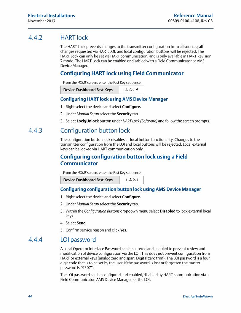
Reference Manual00809-0100-4108, Rev CB
Electrical Installations November 2017
4.4.2 HART lockThe HART Lock prevents changes to the transmitter configuration from all sources; all changes requested via HART, LOI, and local configuration buttons will be rejected. The HART Lock can only be set via HART communication, and is only available in HART Revision 7 mode. The HART Lock can be enabled or disabled with a Field Communicator or AMS Device Manager.
Configuring HART lock using Field Communicator
Configuring HART lock using AMS Device Manager
1. Right select the device and select Configure.
2. Under Manual Setup select the Security tab.
3. Select Lock/Unlock button under HART Lock (Software) and follow the screen prompts.
4.4.3 Configuration button lockThe configuration button lock disables all local button functionality. Changes to the transmitter configuration from the LOI and local buttons will be rejected. Local external keys can be locked via HART communication only.
Configuring configuration button lock using a Field Communicator
Configuring configuration button lock using AMS Device Manager
1. Right select the device and select Configure.
2. Under Manual Setup select the Security tab.
3. Within the Configuration Buttons dropdown menu select Disabled to lock external local keys.
4. Select Send.
5. Confirm service reason and click Yes.
4.4.4 LOI passwordA Local Operator Interface Password can be entered and enabled to prevent review and modification of device configuration via the LOI. This does not prevent configuration from HART or external keys (analog zero and span; Digital zero trim). The LOI password is a four digit code that is to be set by the user. If the password is lost or forgotten the master password is “9307”.
The LOI password can be configured and enabled/disabled by HART communication via a Field Communicator, AMS Device Manager, or the LOI.
From the HOME screen, enter the Fast Key sequence
Device Dashboard Fast Keys 2, 2, 6, 4
From the HOME screen, enter the Fast Key sequence
Device Dashboard Fast Keys 2, 2, 6, 3
44 Electrical Installations

Reference Manual 00809-0100-4108, Rev CB
Electrical InstallationsNovember 2017
Configuring password with Field Communicator
Configuring password with AMS Device Manager
1. Right select the device and select Configure.
2. Under Manual Setup select the Security tab.
3. Within the LOI select the Configure Password button and follow the screen prompts.
Configuring LOI password using LOI
Figure 4-3. LOI Password
4.5 Setting transmitter alarmOn the electronics board is an alarm switch, reference Figure 4-2 on page 43 for switch location. Follow the steps below to change the alarm switch location:
1. Set loop to manual and remove power.
2. Remove transmitter housing cover.
3. Use a small screwdriver to slide switch to desired position.
4. Replace transmitter cover; cover must be fully engaged to comply with explosion proof requirements.
From the HOME screen, enter the Fast Key sequence
Device Dashboard Fast Keys 2, 2, 6, 5, 2
EXTENDED MENUCALIBRATDAMPINGTRANSFER FUNCTSCALED VARIABASSIGN PTAGALARM SAT VALUESPASSWORDPASSWORDSIMULATEHART REVBACK TO MENUEXIT MENU
PASSWORDPASSWORD ENABLECHANGE PASSWORDBACK TO MENUEXIT MENU
VIEW CONFIGZERO TRIMUNITSRERANGELOOP TESTDISPLAYEXTENDED MENUEXTENDED MENUEXIT MENU
45Electrical Installations
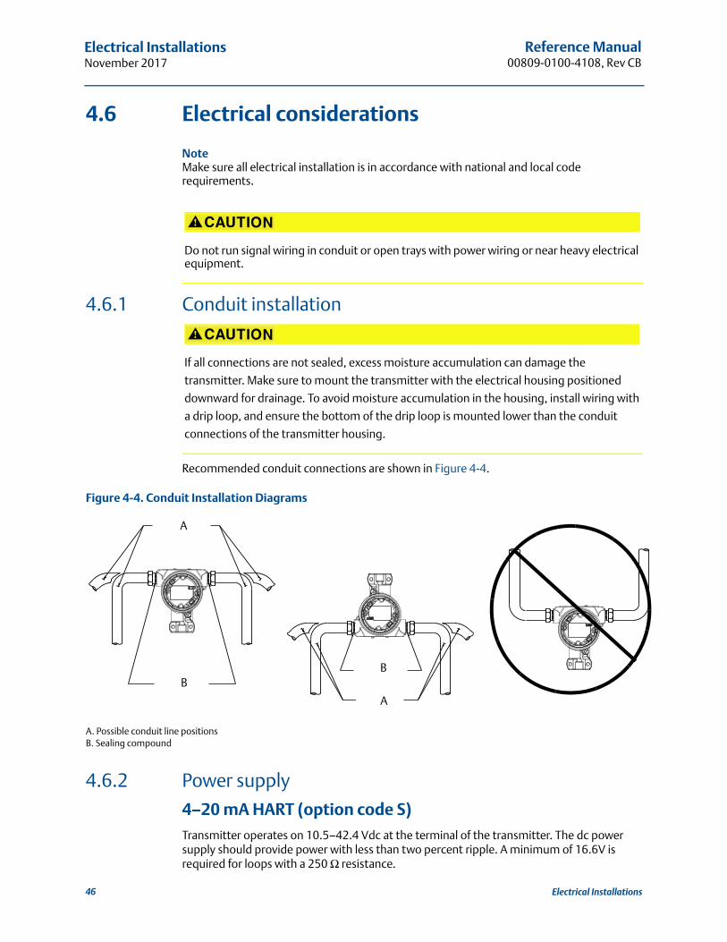
Reference Manual00809-0100-4108, Rev CB
Electrical Installations November 2017
4.6 Electrical considerations
NoteMake sure all electrical installation is in accordance with national and local code requirements.
4.6.1 Conduit installation
Recommended conduit connections are shown in Figure 4-4.
Figure 4-4. Conduit Installation Diagrams
A. Possible conduit line positionsB. Sealing compound
4.6.2 Power supply
4–20 mA HART (option code S)Transmitter operates on 10.5–42.4 Vdc at the terminal of the transmitter. The dc power supply should provide power with less than two percent ripple. A minimum of 16.6V is required for loops with a 250 Ω resistance.
Do not run signal wiring in conduit or open trays with power wiring or near heavy electrical equipment.
If all connections are not sealed, excess moisture accumulation can damage the
transmitter. Make sure to mount the transmitter with the electrical housing positioned
downward for drainage. To avoid moisture accumulation in the housing, install wiring with
a drip loop, and ensure the bottom of the drip loop is mounted lower than the conduit
connections of the transmitter housing.
B
A
B
A
46 Electrical Installations
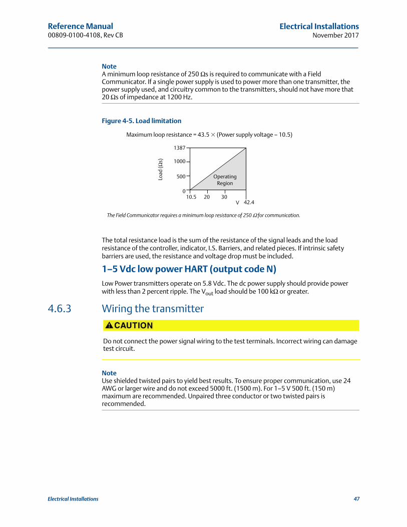
Reference Manual 00809-0100-4108, Rev CB
Electrical InstallationsNovember 2017
NoteA minimum loop resistance of 250 Ωs is required to communicate with a Field Communicator. If a single power supply is used to power more than one transmitter, the power supply used, and circuitry common to the transmitters, should not have more that 20 Ωs of impedance at 1200 Hz.
Figure 4-5. Load limitation
The total resistance load is the sum of the resistance of the signal leads and the load resistance of the controller, indicator, I.S. Barriers, and related pieces. If intrinsic safety barriers are used, the resistance and voltage drop must be included.
1–5 Vdc low power HART (output code N)Low Power transmitters operate on 5.8 Vdc. The dc power supply should provide power with less than 2 percent ripple. The Vout load should be 100 kΩ or greater.
4.6.3 Wiring the transmitter
NoteUse shielded twisted pairs to yield best results. To ensure proper communication, use 24 AWG or larger wire and do not exceed 5000 ft. (1500 m). For 1–5 V 500 ft. (150 m) maximum are recommended. Unpaired three conductor or two twisted pairs is recommended.
Maximum loop resistance = 43.5 � (Power supply voltage – 10.5)
The Field Communicator requires a minimum loop resistance of 250 Ω for communication.
Do not connect the power signal wiring to the test terminals. Incorrect wiring can damage test circuit.
V
Load
(Ωs)
OperatingRegion
1387
1000
500
010.5 20 30
42.4
47Electrical Installations

Reference Manual00809-0100-4108, Rev CB
Electrical Installations November 2017
Figure 4-6. Wiring the Transmitter (4–20 mA HART)
A. DC power supplyB. R L≥ 250 (necessary for HART communication only)
Figure 4-7. Wiring the Transmitter (1–5 Vdc Low Power)
A. DC power supplyB. Voltmeter
Perform the following procedure to make wiring connections:
1. Remove the housing cover on terminal compartment side. Do not remove the cover in explosive atmospheres when the circuit is live. Signal wiring supplies all power to the transmitter.
2. For 4–20 mA HART output, connect the positive lead to the terminal marked (pwr/comm+) and the negative lead to the terminal marked (pwr/comm–). Do not connect the powered signal wiring to the test terminals. Power could damage the test diode.
a. For 1–5 Vdc HART Output, connect the positive lead to (PWR +) and the negative to the (PWR–). Do not connect the powered signal wiring to the test terminals. Power could damage the test diode.
3. Ensure full contact with Terminal Block screw and washer. When using a direct wiring method, wrap wire clockwise to ensure it is in place when tightening the terminal block screw.
A
B
A
B
48 Electrical Installations

Reference Manual 00809-0100-4108, Rev CB
Electrical InstallationsNovember 2017
NoteThe use of a pin or ferrule wire terminal is not recommended as the connection may be more susceptible to loosening over time or under vibration.
4. Plug and seal unused conduit connection on the transmitter housing to avoid moisture accumulation in the terminal side.
4.6.4 Grounding the transmitter
Signal cable shield groundingSignal cable shield grounding is summarized in Figure 4-8 on page 49. The signal cable shield and unused shield drain wire must be trimmed and insulated, ensuring that the signal cable shield and drain wire do not come in contact with the transmitter case. See “Transmitter case grounding” on page 50 for instructions on grounding the transmitter case. Follow the steps below to correctly ground the signal cable shield:
1. Remove the field terminals housing cover.
2. Connect the signal wire pair at the field terminals as indicated in Figure 4-6.
3. At the field terminals, the cable shield and shield drain wire should be trimmed close and insulated from transmitter housing.
4. Reattach the field terminals housing cover; cover must be fully engaged to comply with explosion proof requirements.
5. At terminations outside the transmitter housing, the cable shield drain wire should be continuously connected.
a. Prior to the termination point, any exposed shield drain wire should be insulated as shown in Figure 4-8 (B).
6. Properly terminate the signal cable shield drain wire to an earth ground at or near the power supply.
Figure 4-8. Wiring Pair and Ground
A. Minimize distanceB. Trim shield and insulateC. Protective grounding terminalD. Insulate shieldE. Connect shield back to the power supply
DP
A
B
C
A
DE
49Electrical Installations

Reference Manual00809-0100-4108, Rev CB
Electrical Installations November 2017
Transmitter case groundingAlways ground the transmitter case in accordance with national and local electrical codes. The most effective transmitter case grounding method is a direct connection to earth ground with minimal impedance. Methods for grounding the transmitter case include:
Internal ground connection: the internal ground connection screw is inside the FIELD TERMINALS side of the electronics housing. This screw is identified by a ground symbol ( ). The ground connection screw is standard on all Rosemount 2088, 2090F, 2090P transmitters. Refer to Figure 4-9 on page 50.
External ground connection: The external ground connection is located on the exterior of the transmitter housing. Refer to Figure 4-9 on page 50. This connection is only available with option T1.
Figure 4-9. Internal Ground Connection
A. Internal ground locationB. External ground locationC. PositiveD. NegativeE. Test
NoteGrounding the transmitter case via threaded conduit connection may not provide sufficient ground continuity.
Transient protection terminal block groundingThe transmitter can withstand electrical transients of the energy level usually encountered in static discharges or induced switching transients. However, high-energy transients, such as those induced in wiring from nearby lightning strikes, can damage the transmitter.
The transient protection terminal block can be ordered as an installed option (Option Code T1) or as a spare part to retrofit existing Rosemount 2088, 2090F, and 2090P transmitters in the field. See “Ordering Information, Specifications, and Drawings” on page 31 for part numbers. The lightning bolt symbol shown in Figure 4-10 on page 51 identifies the transient protection terminal block.
C
D
E
A
B
50 Electrical Installations
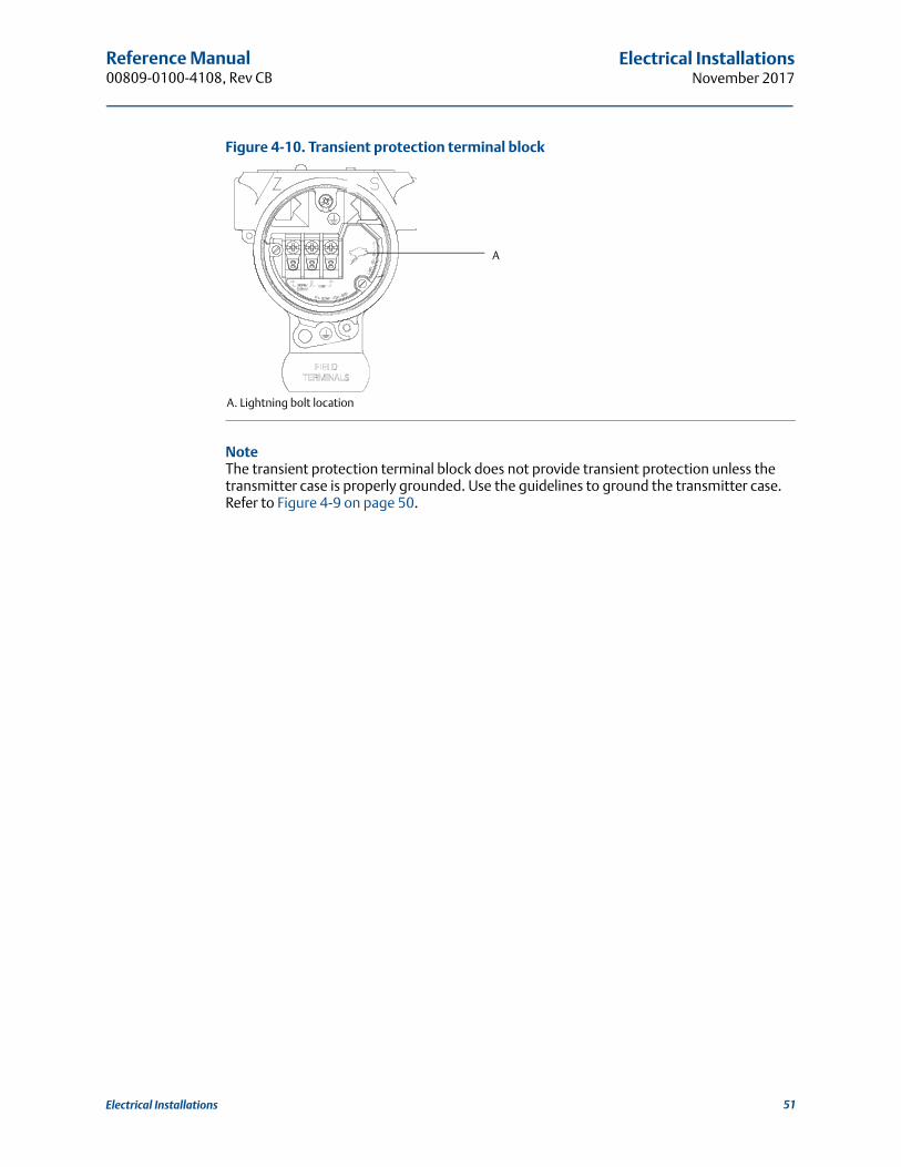
Reference Manual 00809-0100-4108, Rev CB
Electrical InstallationsNovember 2017
Figure 4-10. Transient protection terminal block
A. Lightning bolt location
NoteThe transient protection terminal block does not provide transient protection unless the transmitter case is properly grounded. Use the guidelines to ground the transmitter case. Refer to Figure 4-9 on page 50.
A
51Electrical Installations

Reference Manual00809-0100-4108, Rev CB
Electrical Installations November 2017
52 Electrical Installations

Reference Manual 00809-0100-4108, Rev CB
Operation and maintenanceNovember 2017
Section 5 Operation and maintenance
Overview . . . . . . . . . . . . . . . . . . . . . . . . . . . . . . . . . . . . . . . . . . . . . . . . . . . . . . . . . . . . . . . . page 53Safety messages . . . . . . . . . . . . . . . . . . . . . . . . . . . . . . . . . . . . . . . . . . . . . . . . . . . . . . . . . . page 53Calibration overview . . . . . . . . . . . . . . . . . . . . . . . . . . . . . . . . . . . . . . . . . . . . . . . . . . . . . . page 54Trim the pressure signal . . . . . . . . . . . . . . . . . . . . . . . . . . . . . . . . . . . . . . . . . . . . . . . . . . . page 56Trim the analog output . . . . . . . . . . . . . . . . . . . . . . . . . . . . . . . . . . . . . . . . . . . . . . . . . . . . page 60Switching HART revision . . . . . . . . . . . . . . . . . . . . . . . . . . . . . . . . . . . . . . . . . . . . . . . . . . . page 63
5.1 OverviewThis section contains information on calibrating Rosemount™ 2088 Pressure Transmitters.
Field Communicator, AMS Device Manager and Local Operator Interface (LOI) instructions are given to perform configuration functions.
5.2 Safety messagesProcedures and instructions in this section may require special precautions to ensure the safety of the personnel performing the operations. Information that raises potential safety
issues is indicated by a warning symbol ( ). Refer to the following safety messages before performing an operation preceded by this symbol.
Explosions could result in death or serious injury.
Installation of this transmitter in an explosive environment must be in accordance with the appropriate local, national, and international standards, codes, and practices. Review the approvals section of the reference manual for any restrictions associated with a safe installation. Before connecting a Field Communicator in an explosive atmosphere, ensure the
instruments in the loop are installed in accordance with intrinsically safe or non-incendive field wiring practices.
In an Explosion-Proof/Flameproof installation, do not remove the transmitter covers when power is applied to the unit.
Process leaks may cause harm or result in death.
Install and tighten process connectors before applying pressure.Electrical shock can result in death or serious injury.
Avoid contact with the leads and terminals. High voltage that may be present on leads can cause electrical shock.
53Operation and maintenance

Reference Manual00809-0100-4108, Rev CB
Operation and maintenanceNovember 2017
5.3 Recommended calibration tasks
5.3.1 Field installation tasks1. Perform sensor zero/lower trim: Compensate for mounting pressure effects
a. Refer to Section 3.6: Rosemount 306 Manifold for manifold operation instructions to properly drain/vent valves
2. Set/check basic configuration parameters
a. Output unitsb. Range pointsc. Output typed. Damping Value
5.3.2 Bench calibration tasks1. Perform optional 4–20 mA 1–5 Vdc output trim
2. Perform a sensor trim
a. Zero/lower trim Table 6-1 on page 66 using line pressure effect correction.Refer to Section 3: Rosemount 306 Manifold for manifold drain/vent valve operation instructions.
b. Optional full scale trim. Sets the span of the device and requires accurate calibration equipment.
c. Set/check basic configuration parameters.
5.4 Calibration overviewThe Pressure Transmitter is an accurate instrument that is fully calibrated in the factory. Field calibration is provided to the user to meet plant requirements or industry standards. Complete calibration of the transmitter can be split into two halves: Sensor Calibration and Analog Output Calibration.
Sensor calibration allows the user to adjust the pressure (digital value) reported by the transmitter to be equal to a pressure standard. The sensor calibration can adjust the pressure offset to correct for mounting conditions or line pressure effects. This correction is recommended. The calibration of the pressure range (pressure span or gain correction) requires accurate pressure standards (sources) to provide a full calibration.
Like the Sensor calibration, the analog output can be calibrated to match the user measurement system. The Analog Output Trim (4–20 mA/ 1–5 V output trim) will calibrate the loop at the 4 mA (1 V) and 20 mA (5 V) points.
The Sensor calibration and the analog output calibration combine to match the transmitter’s measurement system to the plant standard.
Absolute pressure transmitters are calibrated at the factory. Trimming adjusts the position of the factory characterization curve. It is possible to degrade performance of the transmitter if any trim is done improperly or with inaccurate equipment.
54 Operation and maintenance

Reference Manual 00809-0100-4108, Rev CB
Operation and maintenanceNovember 2017
Calibrate the sensor Sensor trim (page 57)
Zero trim (page 59)
Calibrate the 4–20 mA output 4–20 mA/ 1–5V Output trim (page 60)
4–20 mA/ 1–5V Output trim using other scale (page 61)
5.4.1 Determining necessary sensor trimsBench calibrations allow for calibrating the instrument for its desired range of operation. Straight forward connections to pressure source allow for a full calibration at the planned operating points. Exercising the Transmitter over the desired pressure range allows for verification of the analog output. “Trim the pressure signal” on page 56 discusses how the trim operations change the calibration. It is possible to degrade the performance of the transmitter if a trim is done improperly or with inaccurate equipment. The transmitter can be set back to factory settings using the “Recall factory trim—sensor trim” on page 59.
Determine the necessary trims with the following steps.
1. Apply pressure.
2. Check digital pressure, if the digital pressure does not match the applied pressure, perform a digital trim. See “Perform a sensor trim” on page 57.
3. Check reported analog output against the live analog output. If they do not match, perform an analog output trim. See “Performing digital-to-analog trim (4–20mA/ 1–5 V output trim)” on page 60.
Trimming with configuration buttonsLocal configuration buttons are external buttons located underneath the top tag of the transmitter. There are two possible sets of local configuration buttons that can be ordered with the Rosemount 2088 and used to perform trim operations: Digital zero trim and LOI. To access the buttons, loosen screw and rotate top tag until buttons are visible.
LOI (M4): Can perform both digital Sensor Trim and the 4–20mA Output Trim (analog output trim). Follow the same procedures listed in trimming with Field Communicator or AMS Device Manager listed below.
Digital zero trim (DZ): Used for performing a sensor zero trim. See “Determining calibration frequency” on page 56 for trim instructions.
All configuration changes should be monitored by a display or by measuring the loop output. Figure 5-1 shows the physical differences between the two sets of buttons.
Figure 5-1. Local Configuration Button Options
A. LOI - green retainerB. Digital zero trim- blue retainer
A B
55Operation and maintenance
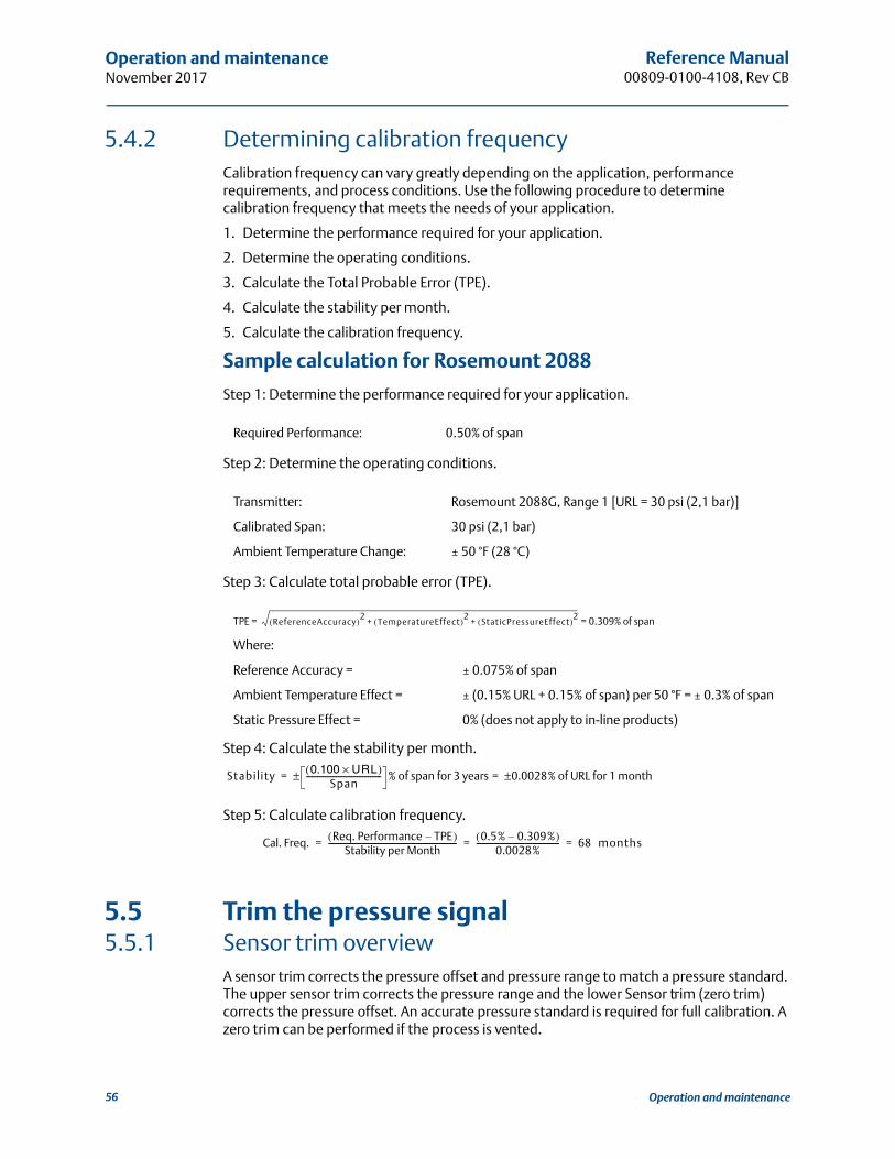
Reference Manual00809-0100-4108, Rev CB
Operation and maintenanceNovember 2017
5.4.2 Determining calibration frequencyCalibration frequency can vary greatly depending on the application, performance requirements, and process conditions. Use the following procedure to determine calibration frequency that meets the needs of your application.
1. Determine the performance required for your application.
2. Determine the operating conditions.
3. Calculate the Total Probable Error (TPE).
4. Calculate the stability per month.
5. Calculate the calibration frequency.
Sample calculation for Rosemount 2088
Step 1: Determine the performance required for your application.
Step 2: Determine the operating conditions.
Step 3: Calculate total probable error (TPE).
Step 4: Calculate the stability per month.
Step 5: Calculate calibration frequency.
5.5 Trim the pressure signal5.5.1 Sensor trim overview
A sensor trim corrects the pressure offset and pressure range to match a pressure standard. The upper sensor trim corrects the pressure range and the lower Sensor trim (zero trim) corrects the pressure offset. An accurate pressure standard is required for full calibration. A zero trim can be performed if the process is vented.
Required Performance: 0.50% of span
Transmitter: Rosemount 2088G, Range 1 [URL = 30 psi (2,1 bar)]
Calibrated Span: 30 psi (2,1 bar)
Ambient Temperature Change: ± 50 °F (28 °C)
TPE = = 0.309% of span
Where:
Reference Accuracy = ± 0.075% of span
Ambient Temperature Effect = ± (0.15% URL + 0.15% of span) per 50 °F = ± 0.3% of span
Static Pressure Effect = 0% (does not apply to in-line products)
ReferenceAccuracy( )2TemperatureEffect( )2
StaticPressureEffect( )2+ +
Stability 0.100 URL×( )Span
---------------------------------------- % of span for 3 years 0.0028% of URL for 1 month±=±=
Cal. Freq. Req. Performance TPE–( )Stability per Month
-------------------------------------------------------------------- 0.5% 0.309%–( )0.0028%
-------------------------------------------- 68xmonths= = =
56 Operation and maintenance
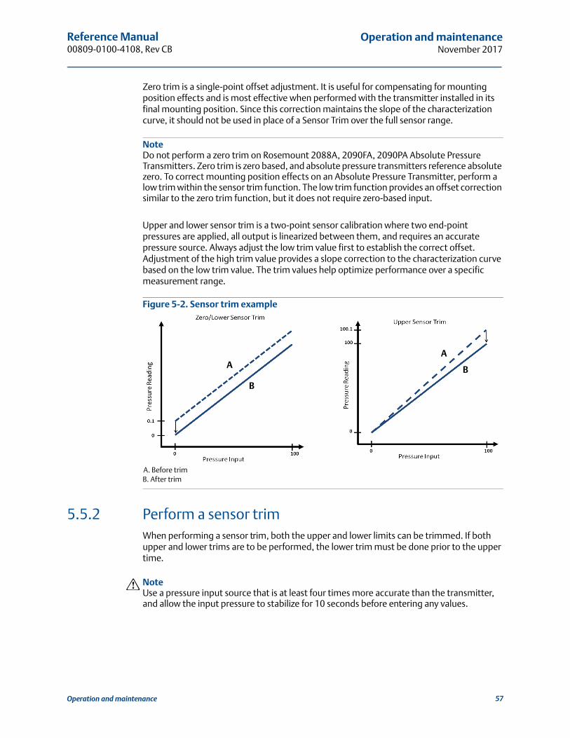
Reference Manual 00809-0100-4108, Rev CB
Operation and maintenanceNovember 2017
Zero trim is a single-point offset adjustment. It is useful for compensating for mounting position effects and is most effective when performed with the transmitter installed in its final mounting position. Since this correction maintains the slope of the characterization curve, it should not be used in place of a Sensor Trim over the full sensor range.
NoteDo not perform a zero trim on Rosemount 2088A, 2090FA, 2090PA Absolute Pressure Transmitters. Zero trim is zero based, and absolute pressure transmitters reference absolute zero. To correct mounting position effects on an Absolute Pressure Transmitter, perform a low trim within the sensor trim function. The low trim function provides an offset correction similar to the zero trim function, but it does not require zero-based input.
Upper and lower sensor trim is a two-point sensor calibration where two end-point pressures are applied, all output is linearized between them, and requires an accurate pressure source. Always adjust the low trim value first to establish the correct offset. Adjustment of the high trim value provides a slope correction to the characterization curve based on the low trim value. The trim values help optimize performance over a specific measurement range.
Figure 5-2. Sensor trim example
A. Before trimB. After trim
5.5.2 Perform a sensor trim When performing a sensor trim, both the upper and lower limits can be trimmed. If both upper and lower trims are to be performed, the lower trim must be done prior to the upper time.
NoteUse a pressure input source that is at least four times more accurate than the transmitter, and allow the input pressure to stabilize for 10 seconds before entering any values.
A
B
BA
57Operation and maintenance

Reference Manual00809-0100-4108, Rev CB
Operation and maintenanceNovember 2017
Performing a sensor trim with a Field CommunicatorFrom the HOME screen, enter the Fast Key sequence and follow the steps within the Field Communicator to complete the sensor trim.
To calibrate the sensor with a Field Communicator using the sensor trim function, perform the following procedure:
1. Select 2: Lower Sensor Trim.
NoteSelect pressure points so that lower and upper values are equal to or outside the expected process operation range. This can be done by going to“Rerange the transmitter” on page 13 of Section 2.
2. Follow the commands provided by the Field Communicator to complete the adjustment of the lower value.
3. Select 3: Upper Sensor Trim.
4. Follow the commands provided by the Field Communicator to complete the adjustment of the upper value.
Performing a sensor trim with AMS Device ManagerRight select the device and, under the Method drop down menu, move cursor over Calibrate and, under Sensor Trim, select Lower Sensor Trim.
1. Follow the screen prompts to perform a Sensor Trim using AMS Device Manager.
2. If desired, right select the device and under the Method drop down menu, move cursor over Calibrate and under Sensor Trim and select Upper Sensor Trim
Performing a sensor trim using local operator interfacePerform an upper and lower Sensor trim by referencing Figure 5-3.
Figure 5-3. Sensor trim with LOI
Device Dashboard Fast Keys 3, 4, 1
EXTENDED MENUCALIBRATCALIBRATDAMPINGTRANSFER FUNCTSCALED VARIABASSIGN PVTAGALARM SAT VALUESPASSWORDSIMULATEHART REVBACK TO MENUEXIT MENU
VIEW CONFIGZERO TRIMUNITSRERANGELOOP TESTDISPLAYEXTENDED MENUEXTENDED MENUEXIT MENU
CALIBRATZERO TRIMLOWER TRIMLOWER TRIMUPPER TRIMUPPER TRIMANALOG TRIMFACTORY RECALLBACK TO MENUEXIT MENU
58 Operation and maintenance

Reference Manual 00809-0100-4108, Rev CB
Operation and maintenanceNovember 2017
Performing a digital zero trim (option DZ)A digital zero trim (option DZ) provides the same function as a zero/lower sensor trim, but can be completed in hazardous areas at any given time by simply pushing the zero trim button when the transmitter is at zero pressure. If the transmitter is not close enough to zero when the button is pushed, the command may fail due to excess correction. If ordered, a digital zero trim can be performed by utilizing external configuration buttons located underneath the top tag of the transmitter, see Figure 5-1 on page 55 for DZ button location.
1. Loosen the top tag of the transmitter to expose buttons.
2. Press and hold the digital zero button for at least two seconds, then release to perform a digital zero trim.
5.5.3 Recall factory trim—sensor trimThe recall factory trim-sensor trim command allows the restoration of the as-shipped factory settings of the sensor trim. This command can be useful for recovering from an inadvertent zero trim of an absolute pressure unit or inaccurate pressure source.
Recalling factory trim with a Field CommunicatorFrom the HOME screen, enter the Fast Key sequence and follow the steps within the Field Communicator to complete the sensor trim.
Recalling factory trim with AMS Device Manager1. Right select on the device and, under the Method drop down menu, move cursor over
Calibrate and select Restore Factory Calibration.
2. Set the control loop to manual.
3. Select Next.
4. Select Sensor Trim under Trim to recall and click Next.
5. Follow the screen prompts to recall sensor trim.
Recalling factory trim - sensor trim using local operator interfaceRefer to Figure 5-4 to recall factory sensor trim.
Device Dashboard Fast Keys 3, 4, 3
59Operation and maintenance

Reference Manual00809-0100-4108, Rev CB
Operation and maintenanceNovember 2017
Figure 5-4. Recall Factory Trim - Sensor Trim With Local Operator Interface
5.6 Trim the analog outputThe Analog Output Trim commands allow you to adjust the transmitter’s current output at the 4 and 20 mA (1 – 5 Vdc) points to match the plant standards. This trim is performed after the digital to analog conversion so only the 4–20 mA analog (1– 5 Vdc) signal will be affected. Figure 5-5 graphically shows the two ways the characterization curve is affected when an analog output trim is performed.
Figure 5-5. Analog Output Trim Example
A. Before trimB. After Trim
5.6.1 Performing digital-to-analog trim (4–20mA/ 1–5 V output trim)
NoteIf a resistor is added to the loop, ensure that the power supply is sufficient to power the transmitter to a 20 mA output with additional loop resistance. Refer to “Power supply” on page 46.
EXTENDED MENUCALIBRATCALIBRATDAMPINGTRANSFER FUNCTSCALED VARIABASSIGN PVTAGALARM SAT VALUESPASSWORDSIMULATEHART REVBACK TO MENUEXIT MENU
VIEW CONFIGZERO TRIMUNITSRERANGELOOP TESTDISPLAYEXTENDED MENUEXTENDED MENUEXIT MENU
CALIBRATZERO TRIMLOWER TRIMUPPER TRIMANALOG TRIMFACTORY RECALLFACTORY RECALLBACK TO MENUEXIT MENU
FACTORY RECALLSENSOR RECALLSENSOR RECALLANALOG RECALLBACK TO MENUEXIT MENU
A
A
B
B
mA Output mA Output
60 Operation and maintenance

Reference Manual 00809-0100-4108, Rev CB
Operation and maintenanceNovember 2017
Performing a 4–20 mA/ 1–5 V output trim with a Field CommunicatorFrom the HOME screen, enter the Fast Key sequence and follow the steps within the Field Communicator to complete the 4–20 mA output trim.
Performing a 4–20 mA/ 1–5 V output trim with AMS Device ManagerRight select the device and, under the Method drop down menu, move cursor over Calibrate and select Analog Calibration.
1. Select Digital to Analog Trim.
2. Follow the screen prompts to perform a 4–20 mA output trim.
Performing 4–20 mA/ 1–5 V output trim using local operator interface
Figure 5-6. 4–20mA output trim using local operator interface
5.6.2 Performing digital-to-analog trim (4–20mA/ 1–5 V output trim) using other scaleThe scaled 4–20 mA output Trim command matches the 4 and 20 mA points to a user selectable reference scale other than 4 and 20 mA [for example, 2 to 10 volts if measuring across a 500 Ω load, or 0 to 100 percent if measuring from a Distributed Control System (DCS)]. To perform a scaled 4–20 mA output trim, connect an accurate reference meter to the transmitter and trim the output signal to scale, as outlined in the output trim procedure.
Device Dashboard Fast Keys 3, 4, 2, 1
EXTENDED MENUCALIBRATCALIBRATDAMPINGTRANSFER FUNCTSCALED VARIABASSIGN PVTAGALARM SAT VALUESPASSWORDSIMULATEHART REVBACK TO MENUEXIT MENU
VIEW CONFIGZERO TRIMUNITSRERANGELOOP TESTDISPLAYEXTENDED MENUEXTENDED MENUEXIT MENU
CALIBRATZERO TRIMLOWER TRIMUPPER TRIMANALOG TRIMANALOG TRIMFACTORY RECALLBACK TO MENUEXIT MENU
61Operation and maintenance

Reference Manual00809-0100-4108, Rev CB
Operation and maintenanceNovember 2017
Performing a 4–20/ 1–5 V mA output trim using other scale with a Field CommunicatorFrom the HOME screen, enter the Fast Key sequence and follow the steps within the Field Communicator to complete the 4–20 mA output trim using other scale.
Performing a 4–20 mA/ 1–5 V output trim using other scale with AMS Device Manager1. Right select the device and under the Method drop down menu, move cursor over
Calibrate and select Analog Calibration.
2. Select Scaled Digital to Analog Trim.
3. Follow screen prompts to perform a 4–20mA/ 1–5 V output trim.
5.6.3 Recalling factory trim—analog outputThe Recall Factory Trim—Analog Output command allows the restoration of the as-shipped factory settings of the analog output trim. This command can be useful for recovering from an inadvertent trim, incorrect Plant Standard or faulty meter.
Recalling factory trim - analog output with a Field CommunicatorFrom the HOME screen, enter the Fast Key sequence and follow the steps within the Field Communicator to complete the digital to analog trim using other scale.
Recalling factory trim - analog output with AMS Device Manager1. Right select the device and, under the Method drop down menu, move cursor over
Calibrate and select Restore Factory Calibration.
2. Select Next to set the control loop to manual.
3. Select Analog Output Trim under Select trim to recall and click Next.
4. Follow screen prompts to recall analog output trim.
Recalling factory trim - analog output with LOIReference Figure 5-7 for LOI instructions.
Device Dashboard Fast Keys 3, 4, 2, 2
Device Dashboard Fast Keys 3, 4, 3
62 Operation and maintenance

Reference Manual 00809-0100-4108, Rev CB
Operation and maintenanceNovember 2017
Figure 5-7. Recall factory Trim – Analog Output with LOI
5.7 Switching HART revisionSome systems are not capable of communicating with HART® Revision 7 devices. The following procedures list how to change HART revisions between HART Revision 7 and HART Revision 5.
5.7.1 Switching HART revision with generic menuIf the HART configuration tool is not capable of communicating with a HART Revision 7 device, it should load a generic menu with limited capability. The following procedures allow for switching between HART Revision 7 and HART Revision 5 from a generic menu.
1. Locate “Message” field.
a. To change to HART Revision 5, Enter: HART5 in the message field.b. To change to HART Revision 7, Enter: HART7 in the message field.
5.7.2 Switching HART revision with Field CommunicatorFrom the HOME screen, enter the Fast Key sequence and follow steps within the Field Communicator to complete the HART revision change.
5.7.3 Switching HART revision with AMS Device Manager1. Select Manual Setup and select HART.
2. Select Change HART Revision, then follow the on screen prompts.
NoteAMS Device Manager versions 10.5 or greater are compatible with HART Revision 7.
From the HOME screen, enter the Fast Key sequence HART5 HART7
Device Dashboard Fast Keys 2, 2, 5, 2, 4 2, 2, 5, 2, 3
EXTENDED MENUCALIBRATCALIBRATDAMPINGTRANSFER FUNCTSCALED VARIABASSIGN PVTAGALARM SAT VALUESPASSWORDSIMULATEHART REVBACK TO MENUEXIT MENU
VIEW CONFIGZERO TRIMUNITSRERANGELOOP TESTDISPLAYEXTENDED MENUEXTENDED MENUEXIT MENU
CALIBRATZERO TRIMLOWER TRIMUPPER TRIMANALOG TRIMFACTORY RECALLFACTORY RECALLBACK TO MENUEXIT MENU
FACTORY RECALLSENSOR RECALLANALOG RECALLANALOG RECALLBACK TO MENUEXIT MENU
63Operation and maintenance

Reference Manual00809-0100-4108, Rev CB
Operation and maintenanceNovember 2017
5.7.4 Switching HART revision with LOINavigate to HART REV within the extended menu and select either HART REV 5 or HART REV 7. Use Figure 5-8 below to change HART Revision:
Figure 5-8. Change HART Revision with LOI
EXTENDED MENUCALIBRATDAMPINGTRANSFER FUNCTSCALED VARIABASSIGN PVTAGALARM SAT VALUESPASSWORDSIMULATEHART REVHART REVBACK TO MENUEXIT MENU
VIEW CONFIGZERO TRIMUNITSRERANGELOOP TESTDISPLAYEXTENDED MENUEXTENDED MENUEXIT MENU
64 Operation and maintenance

Reference Manual 00809-0100-4108, Rev CB
TroubleshootingNovember 2017
Section 6 Troubleshooting
Overview . . . . . . . . . . . . . . . . . . . . . . . . . . . . . . . . . . . . . . . . . . . . . . . . . . . . . . . . . . . . . . . . page 65Safety messages . . . . . . . . . . . . . . . . . . . . . . . . . . . . . . . . . . . . . . . . . . . . . . . . . . . . . . . . . . page 65Diagnostic messages . . . . . . . . . . . . . . . . . . . . . . . . . . . . . . . . . . . . . . . . . . . . . . . . . . . . . . page 68Disassembly procedures . . . . . . . . . . . . . . . . . . . . . . . . . . . . . . . . . . . . . . . . . . . . . . . . . . . page 70Reassembly procedures . . . . . . . . . . . . . . . . . . . . . . . . . . . . . . . . . . . . . . . . . . . . . . . . . . . . page 72
6.1 OverviewTable 6-1 provides summarized maintenance and troubleshooting suggestions for the most common operating problems.
If you suspect malfunction despite the absence of any diagnostic messages on the Field Communicator display, consider using Section 6.3: Diagnostic messages on page 68 to identify any potential problem.
6.2 Safety messagesProcedures and instructions in this section may require special precautions to ensure the safety of the personnel performing the operations. Information that raises potential safety
issues is indicated by a warning symbol ( ). Refer to the following safety messages before performing an operation preceded by this symbol.
Explosions could result in death or serious injury.
Installation of this transmitter in an explosive environment must be in accordance with the appropriate local, national, and international standards, codes, and practices. Review the approvals section of the Rosemount™ 2088, 2090F, and 2090P reference manual for any restrictions associated with a safe installation. Before connecting a Field Communicator in an explosive atmosphere, ensure the
instruments in the loop are installed in accordance with intrinsically safe or non-incendive field wiring practices.
In an Explosion-Proof/Flameproof installation, do not remove the transmitter covers when power is applied to the unit.
Process leaks may cause harm or result in death.
Install and tighten process connectors before applying pressure.Electrical shock can result in death or serious injury.
Avoid contact with the leads and terminals. High voltage that may be present on leads can cause electrical shock.
65Troubleshooting
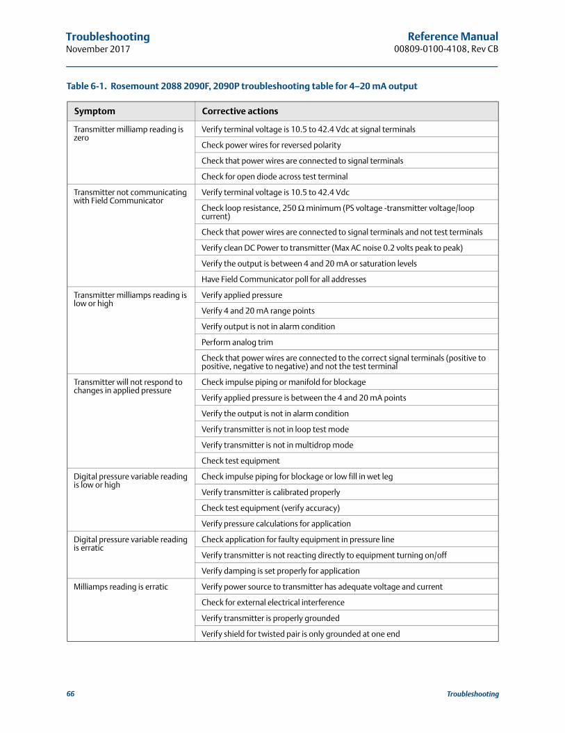
Reference Manual00809-0100-4108, Rev CB
TroubleshootingNovember 2017
Table 6-1. Rosemount 2088 2090F, 2090P troubleshooting table for 4–20 mA output
Symptom Corrective actions
Transmitter milliamp reading is zero
Verify terminal voltage is 10.5 to 42.4 Vdc at signal terminals
Check power wires for reversed polarity
Check that power wires are connected to signal terminals
Check for open diode across test terminal
Transmitter not communicating with Field Communicator
Verify terminal voltage is 10.5 to 42.4 Vdc
Check loop resistance, 250 Ω minimum (PS voltage -transmitter voltage/loop current)
Check that power wires are connected to signal terminals and not test terminals
Verify clean DC Power to transmitter (Max AC noise 0.2 volts peak to peak)
Verify the output is between 4 and 20 mA or saturation levels
Have Field Communicator poll for all addresses
Transmitter milliamps reading is low or high
Verify applied pressure
Verify 4 and 20 mA range points
Verify output is not in alarm condition
Perform analog trim
Check that power wires are connected to the correct signal terminals (positive to positive, negative to negative) and not the test terminal
Transmitter will not respond to changes in applied pressure
Check impulse piping or manifold for blockage
Verify applied pressure is between the 4 and 20 mA points
Verify the output is not in alarm condition
Verify transmitter is not in loop test mode
Verify transmitter is not in multidrop mode
Check test equipment
Digital pressure variable reading is low or high
Check impulse piping for blockage or low fill in wet leg
Verify transmitter is calibrated properly
Check test equipment (verify accuracy)
Verify pressure calculations for application
Digital pressure variable reading is erratic
Check application for faulty equipment in pressure line
Verify transmitter is not reacting directly to equipment turning on/off
Verify damping is set properly for application
Milliamps reading is erratic Verify power source to transmitter has adequate voltage and current
Check for external electrical interference
Verify transmitter is properly grounded
Verify shield for twisted pair is only grounded at one end
66 Troubleshooting
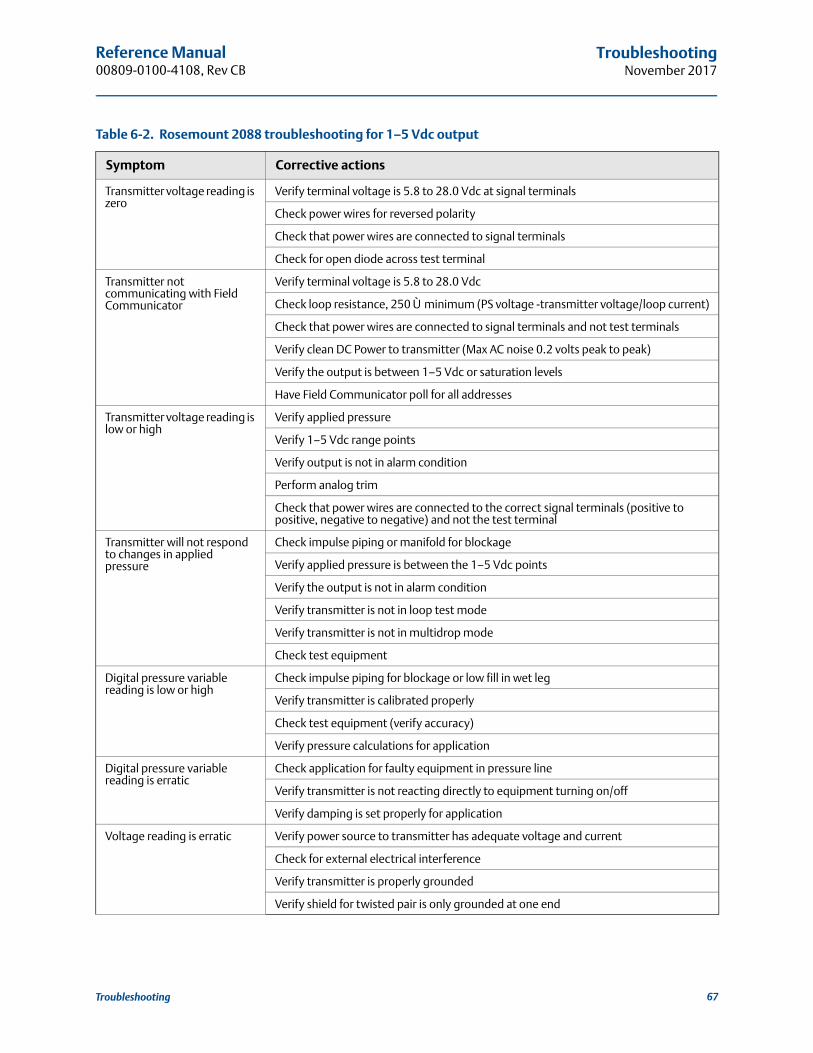
Reference Manual 00809-0100-4108, Rev CB
TroubleshootingNovember 2017
Table 6-2. Rosemount 2088 troubleshooting for 1–5 Vdc output
Symptom Corrective actions
Transmitter voltage reading is zero
Verify terminal voltage is 5.8 to 28.0 Vdc at signal terminals
Check power wires for reversed polarity
Check that power wires are connected to signal terminals
Check for open diode across test terminal
Transmitter not communicating with Field Communicator
Verify terminal voltage is 5.8 to 28.0 Vdc
Check loop resistance, 250 Ù minimum (PS voltage -transmitter voltage/loop current)
Check that power wires are connected to signal terminals and not test terminals
Verify clean DC Power to transmitter (Max AC noise 0.2 volts peak to peak)
Verify the output is between 1–5 Vdc or saturation levels
Have Field Communicator poll for all addresses
Transmitter voltage reading is low or high
Verify applied pressure
Verify 1–5 Vdc range points
Verify output is not in alarm condition
Perform analog trim
Check that power wires are connected to the correct signal terminals (positive to positive, negative to negative) and not the test terminal
Transmitter will not respond to changes in applied pressure
Check impulse piping or manifold for blockage
Verify applied pressure is between the 1–5 Vdc points
Verify the output is not in alarm condition
Verify transmitter is not in loop test mode
Verify transmitter is not in multidrop mode
Check test equipment
Digital pressure variable reading is low or high
Check impulse piping for blockage or low fill in wet leg
Verify transmitter is calibrated properly
Check test equipment (verify accuracy)
Verify pressure calculations for application
Digital pressure variable reading is erratic
Check application for faulty equipment in pressure line
Verify transmitter is not reacting directly to equipment turning on/off
Verify damping is set properly for application
Voltage reading is erratic Verify power source to transmitter has adequate voltage and current
Check for external electrical interference
Verify transmitter is properly grounded
Verify shield for twisted pair is only grounded at one end
67Troubleshooting

Reference Manual00809-0100-4108, Rev CB
TroubleshootingNovember 2017
6.3 Diagnostic messagesListed in the below sections are detailed table of the possible messages that will appear on either the LCD/LOI display, a Field Communicator, or an AMS Device Manager system. Use the tables below to diagnose particular status messages.
Good
Failed – fix now
Maintenance – fix soon
Advisory
Table 6-3. Status: Failed – Fix Now
Table 6-4. Status: Maintenance – Fix Soon
Alert nameLCD display
screenLOI
screenProblem Recommended action
No Pressure Updates
NO PUPDATE
NO PRESS
UPDATE
There are no pressure updates from the sensor to the
electronics
1. Ensure the sensor cable connection to the electronics is tight.
2. Replace the transmitter.
Electronics Board Failure
FAIL BOARD
FAIL BOARD
A failure has been detected in the electronics circuit board
1. Replace the pressure transmitter.
Critical Sensor Data
ErrorMEMRYERROR
MEMORYERROR
A user written parameter does not match the expected
value
1. Confirm and correct all parameters listed in Device Information.
2. Perform a Device Reset.
3. Replace Pressure Transmitter.
Critical Electronics Data Error
A user written parameter does not match the expected
value
1. Confirm and correct all parameters listed in Device Information.
2. Perform a Device Reset.
3. Replace pressure transmitter.
Sensor FailureFAIL
SENSORFAIL
SENSORA failure has been detected in
the pressure sensor1. Replace pressure transmitter.
Incompatible Electronics and Sensor
XMTRMSMTCH
XMTRMSMTCH
The pressure sensor is incompatible with the attached electronics
1. Replace the pressure transmitter.
Alert nameLCD
display screen
LOI screen Problem Recommended action
No Temperature
Updates
NO TUPDATE
NO TEMPUPDATE
There are no temperature updates from the sensor to
the electronics
1. Ensure the sensor cable connection to the electronics is tight.
2. Replace the pressure transmitter.
Pressure Out of Limits
PRES LIMITS
PRES OUTLIMITS
The pressure is either above or below the sensor limits
1. Check the transmitter pressure connection to ensure it is not plugged or the isolating diaphragms are not damaged.
2. Replace the pressure transmitter.
68 Troubleshooting

Reference Manual 00809-0100-4108, Rev CB
TroubleshootingNovember 2017
Table 6-5. Status: Advisory
Sensor Temperature
Beyond Limits TEMPLIMITS
TEMP OUTLIMITS
The sensor temperature has exceeded its safe operating
range
1. Check the process and ambient conditions are within –85 to 194 °F (–65 to 90 °C).
2. Replace the pressure transmitter.
Electronics Temperature
Beyond Limits
The temperature of the electronics has exceeded its
safe operating range.
1. Confirm electronics temperature is within limits of –85 to 194 °F (–65 to 90 °C).
2. Replace the pressure transmitter.
Electronics Board
Parameter Error
MEMRY WARN (also in
advisory)
MEMORY WARN (also in
advisory)
A device parameter does not match the expected value. The error does not affect transmitter operation or
analog output.
1. Replace the pressure transmitter.
Configuration Buttons
Operator Error
STUCK BUTTON
STUCK BUTTON
Device is not responding to button presses.
1. Check configuration buttons are not stuck.
2. Replace the pressure transmitter.
Alert nameLCD
display screen
LOI screen
Problem Recommended action
Non-Critical User Data Warning
MEMRY WARN
MEMORY WARN
A user written parameter does not match expected
value.
1. Confirm and correct all parameters listed in Device Information.
2. Perform a Device Reset.
3. Replace the pressure transmitter.
Sensor Parameter Warning
A user written parameter does not match expected
value.
1. Confirm and correct all parameters listed in Device Information.
2. Perform a Device Reset.
3. Replace pressure transmitter.
LCD Display Update Failure
[If display is not
updating]
[If display is not
updating]
The LCD display is not receiving updates from
the pressure sensor.
1. Check the connection between the LCD display and the circuit board.
2. Replace the LCD display.
3. Replace the pressure transmitter.
Configuration Changed
[none] [none]A recent change has been
made the device by a secondary HART® master such as a handheld device.
1. Verify that the configuration change of the device was intended and expected.
2. Clear this alert by selecting Clear Configuration Changed Status.
3. Connect a HART master such as AMS Device Manager or similar which will automatically clear it.
Alert nameLCD
display screen
LOI screen Problem Recommended action
69Troubleshooting
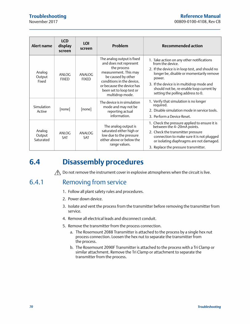
Reference Manual00809-0100-4108, Rev CB
TroubleshootingNovember 2017
6.4 Disassembly proceduresDo not remove the instrument cover in explosive atmospheres when the circuit is live.
6.4.1 Removing from service1. Follow all plant safety rules and procedures.
2. Power down device.
3. Isolate and vent the process from the transmitter before removing the transmitter from service.
4. Remove all electrical leads and disconnect conduit.
5. Remove the transmitter from the process connection.
a. The Rosemount 2088 Transmitter is attached to the process by a single hex nut process connection. Loosen the hex nut to separate the transmitter from the process.
b. The Rosemount 2090F Transmitter is attached to the process with a Tri Clamp or similar attachment. Remove the Tri Clamp or attachment to separate the transmitter from the process.
Analog Output
Fixed
ANLOGFIXED
ANALOGFIXED
The analog output is fixed and does not represent
the process measurement. This may
be caused by other conditions in the device,
or because the device has been set to loop test or
multidrop mode.
1. Take action on any other notifications from the device.
2. If the device is in loop test, and should no longer be, disable or momentarily remove power.
3. If the device is in multidrop mode and should not be, re-enable loop current by setting the polling address to 0.
Simulation Active
[none] [none]
The device is in simulation mode and may not be
reporting actual information.
1. Verify that simulation is no longer required.
2. Disable simulation mode in service tools.
3. Perform a Device Reset.
Analog Output
Saturated
ANLOGSAT
ANALOGSAT
The analog output is saturated either high or low due to the pressure
either above or below the range values.
1. Check the pressure applied to ensure it is between the 4–20mA points.
2. Check the transmitter pressure connection to make sure it is not plugged or isolating diaphragms are not damaged.
3. Replace the pressure transmitter.
Alert nameLCD
display screen
LOI screen
Problem Recommended action
70 Troubleshooting

Reference Manual 00809-0100-4108, Rev CB
TroubleshootingNovember 2017
NoteDo not wrench on neck of transmitter. See warning in “Inline process connection” on page 37.
6. Do not scratch, puncture, or depress the isolating diaphragms.
7. Clean isolating diaphragms with a soft rag and a mild cleaning solution, and rinse with clear water.
6.4.2 Removing terminal blockElectrical connections are located on the terminal block in the compartment labeled “FIELD TERMINALS.”
1. Remove the housing cover from the field terminal side.
2. Loosen the two small screws located on the assembly in the 9 and 5 o’clock positions relative to the top of the transmitter.
3. Pull the entire terminal block out to remove it.
6.4.3 Removing the LOI or LCD displayRosemount 2088 with M4 or M5 option codes have and LOI or LCD display. The transmitter LOI/LCD display are located in the compartment opposite the terminal side. To remove and/or replace the LOI/LCD display, perform the following procedures:
1. Remove the housing cover opposite the field terminal side.
2. Loosen the two captive screws that are visible (See Figure 4-2 on page 43 for screw locations). The two screws anchor the LOI/LCD display to the electronics board and the electronics board to the housing.
3. After the screws are loosened, pull the LOI/LCD display off of the electronics board and out of the housing. Make sure to pull directly backwards so to not bend or damage the connection pins on the electronics board.
NoteDo not attempt to pull out the electronics board from the housing as this could permanently damage the transmitter.
See “Safety messages” on page 65 for complete warning
71Troubleshooting

Reference Manual00809-0100-4108, Rev CB
TroubleshootingNovember 2017
6.5 Reassembly procedures
6.5.1 Installing LOI/LCD Display1. While aligning the captive screws with the respective holes on the electronics board,
connect the LCD/LOI display to the electronics board by pressing down firmly.
2. Ensure that the connecting pins on the back of the LCD fully connect to the front of the electronics board.
3. Fully tighten down the captive screws
4. Replace the housing cover. The transmitter must be fully engaged to meet Explosion-Proof requirementsInstalling terminal block.
6.6 Service supportWithin the United States, call the Emerson™ Instrument and Valve Response Center using the 1-800-654-RSMT (7768) toll-free number. This center, available 24 hours a day, will assist you with any needed information or materials.
The center will ask for product model and serial numbers, and will provide a Return Material Authorization (RMA) number. The center will also ask for the process material to which the product was last exposed.
For inquiries outside of the United States, contact the nearest Emerson representative for RMA instructions.
To expedite the return process outside of the United States, contact the nearest Emerson representative.
5. Emerson Instrument and Valve Response Center representatives will explain the additional information and procedures necessary to return goods exposed to hazardous substances.
Individuals who handle products exposed to a hazardous substance can avoid injury if they are informed of and understand the hazard. The product being returned will require a copy of the required Safety Data Sheet (SDS) for each substance must be included with the returned goods.
72 Troubleshooting

Reference DataNovember 2017
Reference Manual00809-0100-4108, Rev CB
Appendix A Reference data
Rosemount™ 2088 Product Certifications . . . . . . . . . . . . . . . . . . . . . . . . . . . . . . . . . . . . . . . . page 31Ordering Information, Specifications, and Drawings . . . . . . . . . . . . . . . . . . . . . . . . . . . . . . . page 31
A.1 Rosemount™ 2088 Product Certifications
To view current Rosemount 2088 Product Certifications, follow these steps:
1. Go to Emerson.com/Rosemount/2088.
2. Scroll as needed to the green menu bar and click Documents & Drawings.
3. Click Manuals & Guides.
4. Select the appropriate Quick Start Guide.
A.2 Rosemount 2090P Product Certifications
To view current Rosemount 2090P Product Certifications, follow these steps:
1. Go to Emerson.com/Rosemount/2090P.
2. Scroll as needed to the green menu bar and click Documents & Drawings.
3. Click Manuals & Guides.
4. Select the appropriate Quick Start Guide.
A.3 Rosemount 2090F Product Certifications
To view current Rosemount 2090F Product Certifications, follow these steps:
1. Go to Emerson.com/Rosemount/2090F.
2. Scroll as needed to the green menu bar and click Documents & Drawings.
3. Click Manuals & Guides.
4. Select the appropriate Quick Start Guide.
A.4 Ordering Information, Specifications, and Drawings
To view current Rosemount 2088 Product Certifications, follow these steps:
1. Go to Emerson.com/Rosemount/2088.
2. Scroll as needed to the green menu bar and click Documents & Drawings.
3. For installation drawings, click Drawings & Schematics and select the appropriate document.
4. For ordering information, specifications, and dimensional drawings, click Data Sheets & Bulletins and select the appropriate Product Data Sheet.
A.5 Ordering Information, Specifications, and Drawings
To view current Rosemount 2090P Product Certifications, follow these steps:
1. Go to Emerson.com/Rosemount/2090P.
2. Scroll as needed to the green menu bar and click Documents & Drawings.
3. For installation drawings, click Drawings & Schematics and select the appropriate document.
4. For ordering information, specifications, and dimensional drawings, click Data Sheets & Bulletins and select the appropriate Product Data Sheet.
Specifications and Reference Data31

Reference DataNovember 2017
Reference Manual 00809-0100-4108, Rev CB
A.6 Ordering Information, Specifications, and Drawings
To view current Rosemount 2090F Product Certifications, follow these steps:
1. Go to Emerson.com/Rosemount/2090F.
2. Scroll as needed to the green menu bar and click Documents & Drawings.
3. For installation drawings, click Drawings & Schematics and select the appropriate document.
4. For ordering information, specifications, and dimensional drawings, click Data Sheets & Bulletins and select the appropriate Product Data Sheet.
Specifications and Reference Data 32

Field communicator menu trees and Fast KeysNovember 2017
Reference Manual00809-0100-4108, Rev CA
Field communicator menu trees and Fast Keys113
Appendix B Field Communicator menu trees and Fast Keys
Field communicator menu trees . . . . . . . . . . . . . . . . . . . . . . . . . . . . . . . . . . . . . . . . . . page 113Field communicator Fast Keys . . . . . . . . . . . . . . . . . . . . . . . . . . . . . . . . . . . . . . . . . . . . page 117
B.1 Field Communicator menu treesFigure B-1. Field Communicator menu tree: overview
NoteSelections with black circle are only available in HART® Revision 7 mode. Selection will not appear in HART Revision 5 DD.
Home1 Overview2 Configure3 Service Tools
Overview1 Device Status2 Comm Status3 PV4 Analog Output5 Upper Range Value6 Lower Range Value7 Device Information
1 Model Number 12 Model Number 23 Model Number 3
Flange Info1 Process Connection2 Process Connection Material3 O-ring Material4 Drain/Vent Material
Comm Status: Polled1 Communication Change
HART Lock1 Device Lock
LOI Password Protection1 Password Protection
Remote Seal Info1 Num of Remote Seals2 Seal Type3 Fill Fluid4 Diaphragm Material
Alarm Levels1 Alarm Direction2 High Alarm3 High Saturation4 Low Saturation5 Low Alarm
Active Alerts1 Refresh Alerts2 Active Alert 1 3 Active Alert 2 4 Etc
Sensor Module Info1 Serial Number2 Measurement Type3 Configuration4 Sensor Range5 PV Upper Limit6 PV Lower Limit7 Isolator material8 Fill Fluid
Identification1 Tag2 Long Tag 3 Model4 Serial Number5 Date6 Description7 Message8 Model Numbers9 Manufacturer
Security1 Security Switch Status2 External Buttons3 Configuration Buttons4 HART Lock5 LOI Password Protection
Device Information1 Identification2 Revision Numbers 3 Sensor Module Info4 Flange Info 5 Remote Seal Info6 Alarm Levels7 Security
Revision Numbers1 Universal Revision2 Field Device3 Software4 Hardware5 Device Driver Revision

Field communicator menu trees and Fast KeysNovember 2017
Reference Manual 00809-0100-4108, Rev CA
Figure B-2. Field Communicator menu tree: configure - guided setup
NoteSelections with black circle are only available in HART Revision 7 mode. Selection will not appear in HART Revision 5 DD.
Home1 Overview2 Configure3 Service Tools
Configure1 Guided Setup2 Manual Setup3 Alert Setup
Scaled Variable1 SV Data Points2 SV Units3 SV Transfer Function4 SV Linear Offset5 SV Cutoff mode6 SV Low Cutoff7 Scaled Variable
Configure Burst Mode1 Burst Message 12 Message 1 Content3 Message 1 Variables
Basic Setup1 Device Tagging2 Units of Measure/Damping3 Variable Mapping4 Analog Output5 Alarm/Saturation Values
Device Tagging1 Tag2 Long Tag3 Description4 Message5 Date
Guided Setup1 Basic Setup2 Zero Trim3 Configure Display4 Scaled Variable5 Configure Burst Mode
Configure Display1 Pressure2 Scaled Variable3 Sensor Temperature4 Percent of Range5 Analog Output6 Review Parameters at Start-up
Variable Mapping1 Primary Variable2 Second Variable3 Third Variable4 Fourth Variable
Analog Output1 Primary Variable2 Upper Range Value3 Lower Range Value
Message 1 Variables1 First and Trigger Variable2 Second Variable3 Third Variable4 Fourth Variable
Units of Measure/Damping1 Units of Measure2 Damping
Units of Measure1 Pressure2 Sensor Temp Units
Alarm/Saturation Values1 Alarm Direction 2 High Alarm3 High Saturation4 Low Saturation5 Low Alarm6 Config Alarm/Sat Values
Field communicator menu trees and Fast Keys 114
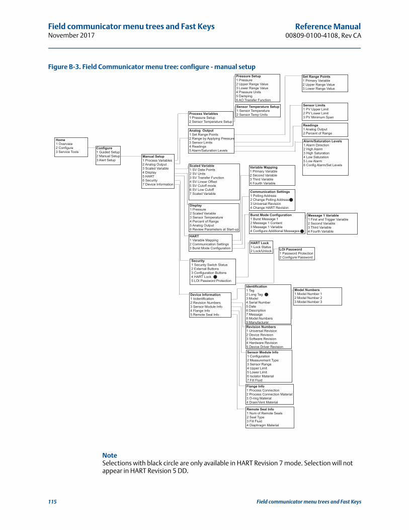
Field communicator menu trees and Fast KeysNovember 2017
Reference Manual00809-0100-4108, Rev CA
Figure B-3. Field Communicator menu tree: configure - manual setup
NoteSelections with black circle are only available in HART Revision 7 mode. Selection will not appear in HART Revision 5 DD.
456
345
Home1 Overview2 Configure3 Service Tools
Configure1 Guided Setup2 Manual Setup3 Alert Setup
Display1 Pressure2 Scaled Variable3 Sensor Temperature4 Percent of Range5 Analog Output6 Review Parameters at Start-up
HART1 Variable Mapping2 Communication Settings3 Burst Mode Configuration
Security1 Security Switch Status2 External Buttons3 Configuration Buttons4 HART Lock5 LOI Password Protection
Scaled Variable1 SV Data Points2 SV Units3 SV Transfer Function4 SV Linear Offset5 SV Cutoff mode6 SV Low Cutoff7 Scaled Variable
Process Variables1 Pressure Setup2 Sensor Temperature Setup
Pressure Setup1 Pressure2 Upper Range Value3 Lower Range Value4 Pressure Units5 Damping6 AO Transfer Function
Sensor Temperature Setup1 Sensor Temperature2 Sensor Temp Units
Device Information1 Indentification2 Revision Numbers3 Sensor Module Info4 Flange Info5 Remote Seal Info
Analog Output1 Set Range Points2 Range by Applying Pressure3 Sensor Limits4 Readings5 Alarm/Saturation Levels
Identification1 Tag2 Long Tag3 Model4 Serial Number5 Date6 Description7 Message8 Model Numbers9 Manufacturer
LOI Password1 Password Protection2 Configure Password
HART Lock1 Lock Status2 Lock/Unlock
Variable Mapping1 Primary Variable2 Second Variable3 Third Variable4 Fourth Variable
Communication Settings1 Polling Address2 Change Polling Address3 Universal Revision4 Change HART Revision
Burst Mode Configuration1 Burst Message 12 Message 1 Content3 Message 1 Variable4 Configure Additional Messages
Message 1 Variable1 First and Trigger Variable2 Second Variable3 Third Variable4 Fourth Variable
Set Range Points1 Primary Variable2 Upper Range Value3 Lower Range Value
Sensor Limits1 PV Upper Limit2 PV Lower Limit3 PV Minimum Span
Alarm/Saturation Levels1 Alarm Direction2 High Alarm3 High Saturation4 Low Saturation5 Low Alarm6 Config Alarm/Set Levels
Readings1 Analog Output2 Percent of Range
Manual Setup1 Process Variables2 Analog Output3 Scaled Variable4 Display5 HART6 Security7 Device Information
Revision Numbers1 Universal Revision2 Device Revision3 Software Revision4 Hardware Revision5 Device Driver Revision Sensor Module Info1 Configuration2 Measurement Type3 Sensor Range4 Upper Limit5 Lower Limit6 Isolator Material7 Fill Fluid
Flange Info1 Process Connection2 Process Connection Material3 O-ring Material4 Drain/Vent Material
Model Numbers1 Model Number 12 Model Number 23 Model Number 3
Remote Seal Info1 Num of Remote Seals2 Seal Type3 Fill Fluid4 Diaphragm Material
Field communicator menu trees and Fast Keys115

Field communicator menu trees and Fast KeysNovember 2017
Reference Manual 00809-0100-4108, Rev CA
Figure B-4. Field Communicator menu tree: configure - alert setupHome1 Overview2 Configure3 Service Tools
Configure1 Guided Setup2 Manual Setup3 Alert Setup
Alert Setup1 Pressure Alert2 Temperature Alert3 Alarm/Saturation Levels
Alarm/Saturation Levels1 Alarm Direction2 High Alarm3 High Saturation4 Low Saturation5 Low Alarm6 Config Alarm/Sat Levels
Temperature Alert1 Configure Alert2 Alert Mode3 High Alert Value4 Low Alert Value5 Trend
Pressure Alert1 Configure Alert2 Alert Mode3 High Alert Value4 Low Alert Value5 Trend
Alarm/Saturation Levels
Field communicator menu trees and Fast Keys 116

Field communicator menu trees and Fast KeysNovember 2017
Reference Manual00809-0100-4108, Rev CA
Figure B-5. Field Communicator menu tree - service tools
NoteSelections with black circle are only available in HART Revision 7 mode. Selection will not appear in HART Revision 5 DD.
B.2 Field communicator Fast Keys A () indicates the basic configuration parameters. At minimum these parameters should
be verified as a part of configuration and startup.
A (7) indicates availability only in HART revision 7 mode.
Table B-1. Device revision 9 and 10 (HART 7), DD revision 1 Fast Key sequence
Function
Fast Key sequence
HART 7 HART 5
Alarm and Saturation Levels 2, 2, 2, 5 2, 2, 2, 5
Damping 2, 2, 1, 1, 5 2, 2, 1, 1, 5
Primary Variable 2, 2, 5, 1, 1 2, 2, 5, 1, 1
Home1 Overview2 Configure3 Service Tools
Trends1 Pressure2 Scaled Variable3 Sensor Temperature
Pressure1 Pressure2 Status
Scaled Variable1 Scaled Variable2 Status
Sensor Temperature1 Sensor Temperature2 Status
Analog Output1 Analog Output
Percent of Range1 Percent of Range
Maintenance1 Pressure Calibration2 Analog Calibration3 Restore Factory Calibration4 Security5 Locate Device6 Device Reset
Pressure Calibration1 Upper Sensor Trim2 Lower Sensor Trim3 Zero Trim4 Damping5 AO Transfer Function6 Last Calibration Points7 Sensor Limits
AO Transfer Function1 Upper Calibration Points2 Lower Calibration Points
LOI Password Protection1 Password Protection2 Configure Password
HART Lock1 Device Lock2 Lock/Unlock
Sensor Limits1 PV Upper Limit2 PV Lower Limit3 PV Minimum Span
Security1 Security Switch Status2 External Buttons3 Configuration Buttons4 HART Lock5 LOI Password Protection
Simulate1 Loop Test2 Pressure3 Scaled Variable4 Sensor Temperature
Active Alerts1 Refresh Alerts2 Active Alert 1 3 Active Alert 2 4 Etc.
Service Tools1 Active Alerts2 Variables3 Trends4 Maintenance5 Simulate
Variables1 Variable Summary2 Pressure3 Scaled Variable4 Analog Output5 Percent of Range6 Sensor Temperature
Field communicator menu trees and Fast Keys117
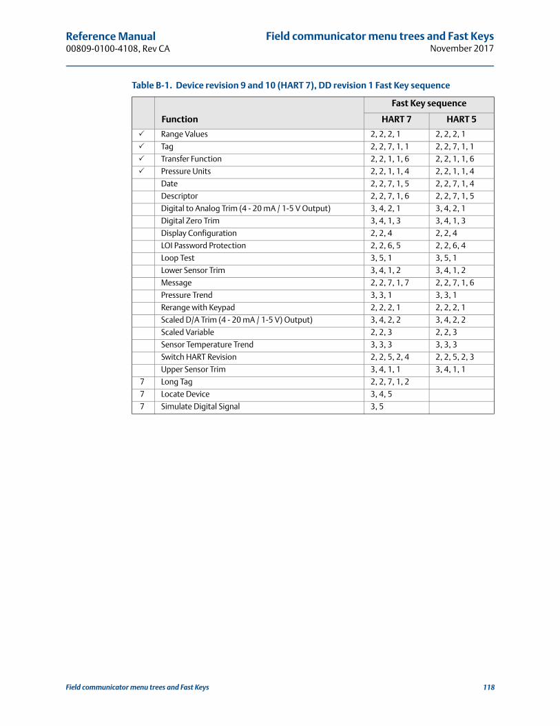
Field communicator menu trees and Fast KeysNovember 2017
Reference Manual 00809-0100-4108, Rev CA
Range Values 2, 2, 2, 1 2, 2, 2, 1
Tag 2, 2, 7, 1, 1 2, 2, 7, 1, 1
Transfer Function 2, 2, 1, 1, 6 2, 2, 1, 1, 6
Pressure Units 2, 2, 1, 1, 4 2, 2, 1, 1, 4
Date 2, 2, 7, 1, 5 2, 2, 7, 1, 4
Descriptor 2, 2, 7, 1, 6 2, 2, 7, 1, 5
Digital to Analog Trim (4 - 20 mA / 1-5 V Output) 3, 4, 2, 1 3, 4, 2, 1
Digital Zero Trim 3, 4, 1, 3 3, 4, 1, 3
Display Configuration 2, 2, 4 2, 2, 4
LOI Password Protection 2, 2, 6, 5 2, 2, 6, 4
Loop Test 3, 5, 1 3, 5, 1
Lower Sensor Trim 3, 4, 1, 2 3, 4, 1, 2
Message 2, 2, 7, 1, 7 2, 2, 7, 1, 6
Pressure Trend 3, 3, 1 3, 3, 1
Rerange with Keypad 2, 2, 2, 1 2, 2, 2, 1
Scaled D/A Trim (4 - 20 mA / 1-5 V) Output) 3, 4, 2, 2 3, 4, 2, 2
Scaled Variable 2, 2, 3 2, 2, 3
Sensor Temperature Trend 3, 3, 3 3, 3, 3
Switch HART Revision 2, 2, 5, 2, 4 2, 2, 5, 2, 3
Upper Sensor Trim 3, 4, 1, 1 3, 4, 1, 1
7 Long Tag 2, 2, 7, 1, 2
7 Locate Device 3, 4, 5
7 Simulate Digital Signal 3, 5
Table B-1. Device revision 9 and 10 (HART 7), DD revision 1 Fast Key sequence
Function
Fast Key sequence
HART 7 HART 5
Field communicator menu trees and Fast Keys 118
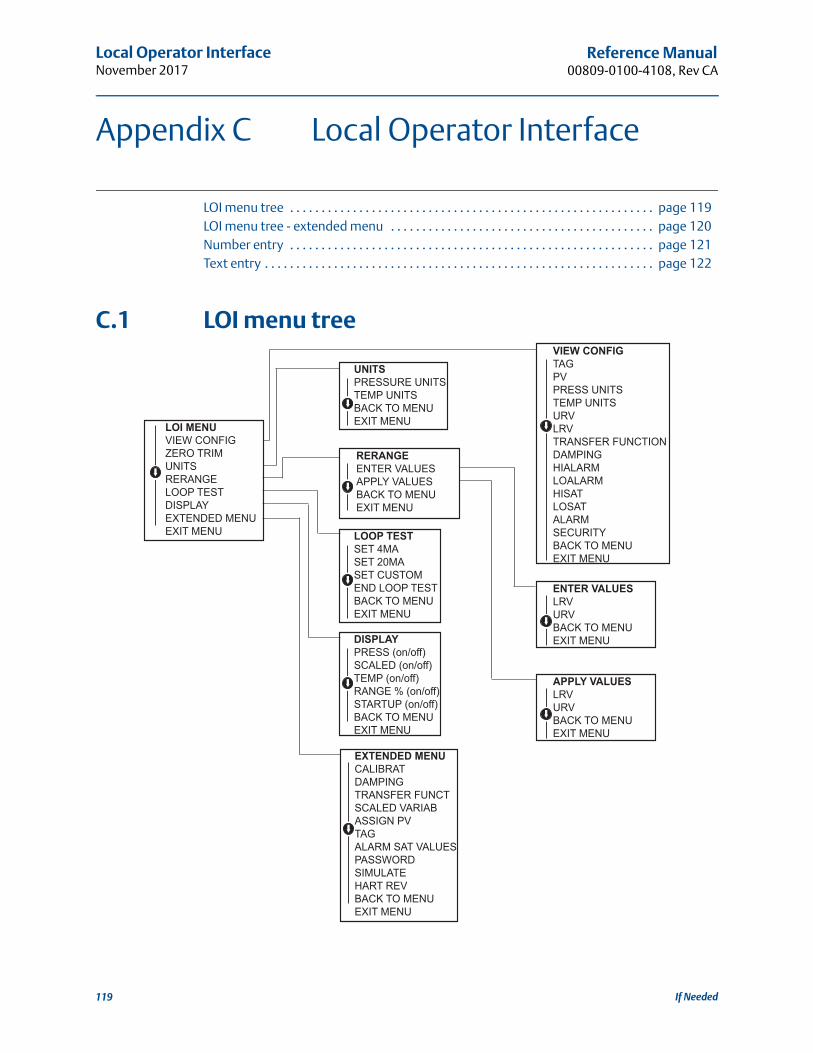
Local Operator InterfaceNovember 2017
Reference Manual00809-0100-4108, Rev CA
Appendix C Local Operator Interface
LOI menu tree . . . . . . . . . . . . . . . . . . . . . . . . . . . . . . . . . . . . . . . . . . . . . . . . . . . . . . . . . . page 119LOI menu tree - extended menu . . . . . . . . . . . . . . . . . . . . . . . . . . . . . . . . . . . . . . . . . . page 120Number entry . . . . . . . . . . . . . . . . . . . . . . . . . . . . . . . . . . . . . . . . . . . . . . . . . . . . . . . . . . page 121Text entry . . . . . . . . . . . . . . . . . . . . . . . . . . . . . . . . . . . . . . . . . . . . . . . . . . . . . . . . . . . . . . page 122
C.1 LOI menu tree
LOI MENUVIEW CONFIGZERO TRIMUNITSRERANGELOOP TESTDISPLAYEXTENDED MENUEXIT MENU
UNITSPRESSURE UNITSTEMP UNITSBACK TO MENUEXIT MENU
RERANGEENTER VALUESAPPLY VALUESBACK TO MENUEXIT MENU
LOOP TESTSET 4MASET 20MASET CUSTOMEND LOOP TESTBACK TO MENUEXIT MENU
DISPLAYPRESS (on/off)SCALED (on/off)TEMP (on/off)RANGE % (on/off)STARTUP (on/off)BACK TO MENUEXIT MENU
EXTENDED MENUCALIBRATDAMPINGTRANSFER FUNCTSCALED VARIABASSIGN PVTAGALARM SAT VALUESPASSWORDSIMULATEHART REVBACK TO MENUEXIT MENU
VIEW CONFIGTAGPVPRESS UNITSTEMP UNITSURVLRVTRANSFER FUNCTIONDAMPINGHIALARMLOALARMHISATLOSATALARMSECURITYBACK TO MENUEXIT MENU
APPLY VALUESLRVURVBACK TO MENUEXIT MENU
ENTER VALUESLRVURVBACK TO MENUEXIT MENU
If Needed119

Local Operator InterfaceNovember 2017
Reference Manual 00809-0100-4108, Rev CA
C.2 LOI menu tree - extended menu
EXTENDED MENUCALIBRATDAMPINGTRANSFER FUNCTSCALED VARIABASSIGN PVTAGALARM SAT VALUESPASSWORDSIMULATEHART REVBACK TO MENUEXIT MENU
CALIBRATZERO TRIMLOWER TRIMUPPER TRIMANALOG TRIMFACTORY RECALLBACK TO MENUEXIT MENU
FACTORY RECALLSENSOR RECALLANALOG RECALLBACK TO MENUEXIT MENU
TRANSFER FUNCTLINEAR TRANSFER FUNCTION SQR ROOT TRANSFER FUNCTIONBACK TO MENUEXIT MENU
SCALED VARIABVIEW SCALEDCONFIG SCALEDBACK TO MENUEXIT MENU
ASSIGN PVPRESSURE SET PVSCALED SET PVBACK TO MENUEXIT MENUALARM SAT VALUESROSEMOUNT VALUESNAMUR VALUESOTHER VALUESBACK TO MENUEXIT MENU
PASSWORDENABLE PASSWORDCHANGE PASSWORDBACK TO MENUEXIT MENU
SIMULATESIMULATE PRESSSIMULATE TEMPSIMULATE SCALEDEND SIMULBACK TO MENUEXIT MENU
HART REVHART7 REVHART5 REVBACK TO MENUEXIT MENU
OTHER VALUESHIGH ALARMLOW ALARMHIGH SATURATIONLOW SATURATIONBACK TO MENUEXIT MENU
If Needed 120
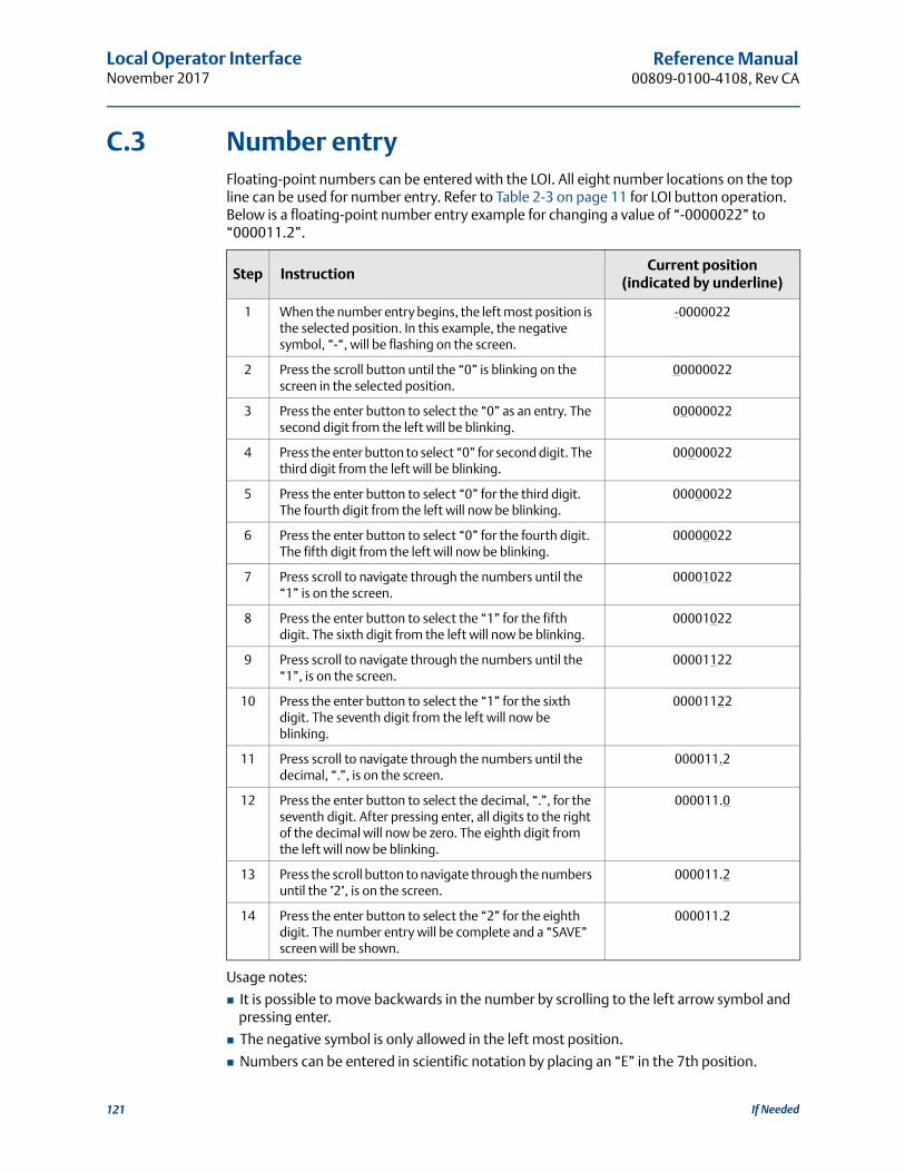
Local Operator InterfaceNovember 2017
Reference Manual00809-0100-4108, Rev CA
C.3 Number entryFloating-point numbers can be entered with the LOI. All eight number locations on the top line can be used for number entry. Refer to Table 2-3 on page 11 for LOI button operation. Below is a floating-point number entry example for changing a value of “-0000022” to “000011.2”.
Usage notes:
It is possible to move backwards in the number by scrolling to the left arrow symbol and pressing enter.
The negative symbol is only allowed in the left most position.
Numbers can be entered in scientific notation by placing an “E” in the 7th position.
Step InstructionCurrent position
(indicated by underline)
1 When the number entry begins, the left most position is the selected position. In this example, the negative symbol, “-“, will be flashing on the screen.
-0000022
2 Press the scroll button until the “0” is blinking on the screen in the selected position.
00000022
3 Press the enter button to select the “0” as an entry. The second digit from the left will be blinking.
00000022
4 Press the enter button to select “0” for second digit. The third digit from the left will be blinking.
00000022
5 Press the enter button to select “0” for the third digit. The fourth digit from the left will now be blinking.
00000022
6 Press the enter button to select “0” for the fourth digit. The fifth digit from the left will now be blinking.
00000022
7 Press scroll to navigate through the numbers until the “1” is on the screen.
00001022
8 Press the enter button to select the “1” for the fifth digit. The sixth digit from the left will now be blinking.
00001022
9 Press scroll to navigate through the numbers until the “1”, is on the screen.
00001122
10 Press the enter button to select the “1” for the sixth digit. The seventh digit from the left will now be blinking.
00001122
11 Press scroll to navigate through the numbers until the decimal, “.”, is on the screen.
000011.2
12 Press the enter button to select the decimal, “.”, for the seventh digit. After pressing enter, all digits to the right of the decimal will now be zero. The eighth digit from the left will now be blinking.
000011.0
13 Press the scroll button to navigate through the numbers until the "2", is on the screen.
000011.2
14 Press the enter button to select the “2” for the eighth digit. The number entry will be complete and a “SAVE” screen will be shown.
000011.2
If Needed121

Local Operator InterfaceNovember 2017
Reference Manual 00809-0100-4108, Rev CA
C.4 Text entry1. Text can be entered with the LOI. Depending on the edited item, up to eight locations on
the top line can be used for text entry. Text entry follows the same rules as the number entry rules in “LOI menu tree” on page 119, except the following characters are available in all locations: A-Z, 0-9, -, /, space.
Usage note:
If the current text contains a character the LOI cannot display, it will be shown as an asterisk “*”.
If Needed 122

47
Reference Manual 00809-0100-4108, Rev CB
IndexNovember 2017
Index
AAddress
Changing . . . . . . . . . . . . . . . . . . . . . . . . . . . . . . . . . . . . 26Analog output trim . . . . . . . . . . . . . . . . . . . . . . . . . . . . . . . . 56Approval
Information . . . . . . . . . . . . . . . . . . . . . . . . . . . . . . . . . . 93
BBlock diagram . . . . . . . . . . . . . . . . . . . . . . . . . . . . . . . . . . . . . . 7Board, electronics . . . . . . . . . . . . . . . . . . . . . . . . . . . . . . . . . 43Bolts
Installation . . . . . . . . . . . . . . . . . . . . . . . . . . . . . . . . . . . 35Brackets
Mounting . . . . . . . . . . . . . . . . . . . . . . . . . . . . . . . . . . . . 32
CCalibration . . . . . . . . . . . . . . . . . . . . . . . . . . . . . . . . . . . . . . . 54
Frequency, determining . . . . . . . . . . . . . . . . . . . . . . . 56Full trim . . . . . . . . . . . . . . . . . . . . . . . . . . . . . . . . . . . . . . 57Recal factory trim
Analog output . . . . . . . . . . . . . . . . . . . . . . . . . . . . 62Sensor trim . . . . . . . . . . . . . . . . . . . . . . . . . . . . . . 59
Sensor trim . . . . . . . . . . . . . . . . . . . . . . . . . . . . . . . . . . . 57Zero trim . . . . . . . . . . . . . . . . . . . . . . . . . . . . . . . . . . . . 57
Certifications . . . . . . . . . . . . . . . . . . . . . . . . . . . . . . . . . . . . . 93Considerations
General . . . . . . . . . . . . . . . . . . . . . . . . . . . . . . . . . . . . . . 30
DDiagrams
Low power . . . . . . . . . . . . . . . . . . . . . . . . . . . . . . . . . 9, 48Multidrop network . . . . . . . . . . . . . . . . . . . . . . . . . . . . 26Typical multidrop network . . . . . . . . . . . . . . . . . . . . . 26
Digital to analog trim . . . . . . . . . . . . . . . . . . . . . . . . . . . . . . 60Other scale . . . . . . . . . . . . . . . . . . . . . . . . . . . . . . . . . . . 61
DisassemblyBefore disassembling . . . . . . . . . . . . . . . . . . . . . . . . . . 70Remove electronics board . . . . . . . . . . . . . . . . . . . . . 71Remove from service . . . . . . . . . . . . . . . . . . . . . . . . . . 70Disassembly procedures . . . . . . . . . . . . . . . . . . . . . . . 70
EElectronics board . . . . . . . . . . . . . . . . . . . . . . . . . . . . . . . . . . 43
FFeatures . . . . . . . . . . . . . . . . . . . . . . . . . . . . . . . . . . . . . . . . . . 2Full trim . . . . . . . . . . . . . . . . . . . . . . . . . . . . . . . . . . . . . . . . . . 57
IImpulse piping . . . . . . . . . . . . . . . . . . . . . . . . . . . . . . . . . . . . 35
Installation . . . . . . . . . . . . . . . . . . . . . . . . . . . . . . . . . . . . . . . 31Bolts . . . . . . . . . . . . . . . . . . . . . . . . . . . . . . . . . . . . . . . . 35Cover . . . . . . . . . . . . . . . . . . . . . . . . . . . . . . . . . . . . . . . . 31HART flowchart . . . . . . . . . . . . . . . . . . . . . . . . . . . . . . . . .5Mechanical considerations . . . . . . . . . . . . . . . . . . . . . 31Model 306 manifold . . . . . . . . . . . . . . . . . . . . . . . . . . . 40Mounting . . . . . . . . . . . . . . . . . . . . . . . . . . . . . . . . . . . . 31
Brackets . . . . . . . . . . . . . . . . . . . . . . . . . . . . . . . . . 32Introduction . . . . . . . . . . . . . . . . . . . . . . . . . . . . . . . . . . . . . . . 1
LLoop
Setting to manual . . . . . . . . . . . . . . . . . . . . . . . . . . . . . 11Low power
Diagrams . . . . . . . . . . . . . . . . . . . . . . . . . . . . . . . . . . 9, 48
MMaintenance . . . . . . . . . . . . . . . . . . . . . . . . . . . . . . . . . . . . . 53Manifold installations . . . . . . . . . . . . . . . . . . . . . . . . . . . . . . 40Manual
Models covered . . . . . . . . . . . . . . . . . . . . . . . . . . . . . . . . .6Use of . . . . . . . . . . . . . . . . . . . . . . . . . . . . . . . . . . . . . . . . .1
Mechanical considerations . . . . . . . . . . . . . . . . . . . . . . . . . 31MountingInstallation . . . . . . . . . . . . . . . . . . . . . . . . . . . . . . . . . . . . . . . 31
Requirements . . . . . . . . . . . . . . . . . . . . . . . . . . . . . . . . 35Multidrop communication
Communicating . . . . . . . . . . . . . . . . . . . . . . . . . . . . . . 27Diagram . . . . . . . . . . . . . . . . . . . . . . . . . . . . . . . . . . . . . 26
OOperation . . . . . . . . . . . . . . . . . . . . . . . . . . . . . . . . . . . . . . . . 53
Block diagram . . . . . . . . . . . . . . . . . . . . . . . . . . . . . . . . . .7Output
Recal factory trim . . . . . . . . . . . . . . . . . . . . . . . . . . . . . 62
PPiping, impulse . . . . . . . . . . . . . . . . . . . . . . . . . . . . . . . . . . . 35Process
Connections . . . . . . . . . . . . . . . . . . . . . . . . . . . . . . . . . . 37Product certifications . . . . . . . . . . . . . . . . . . . . . . . . . . . . . . 93
RReassembly
Attaching sensor module . . . . . . . . . . . . . . . . . . . . . . 72Installing terminal block . . . . . . . . . . . . . . . . . . . . . . . 72
Recall factory trimAnalog output . . . . . . . . . . . . . . . . . . . . . . . . . . . . . . . . 62Sensor trim . . . . . . . . . . . . . . . . . . . . . . . . . . . . . . . . . . . 59
RerangeHART Communicator only . . . . . . . . . . . . . . . . . . . . . 14Pressure input source
With HART Communicator . . . . . . . . . . . . . . . . . 14With local zero and span . . . . . . . . . . . . . . . . . . . 15

48
Reference Manual00809-0100-4108, Rev CB
IndexNovember 2017
Index

3
Reference Manual 00809-0100-4108, Rev CB
November 2017

Reference Manual00809-0100-4108, Rev CA
November 2017
Global HeadquartersEmerson Automation Solutions 6021 Innovation Blvd.Shakopee, MN 55379, USA
+1 800 999 9307 or +1 952 906 8888+1 952 949 7001 [email protected]
North America Regional OfficeEmerson Automation Solutions8200 Market Blvd.Chanhassen, MN 55317, USA
+1 800 999 9307 or +1 952 906 8888+1 952 949 7001 [email protected]
Latin America Regional OfficeEmerson Automation Solutions1300 Concord Terrace, Suite 400Sunrise, FL 33323, USA
+1 954 846 5030+1 954 846 [email protected]
Europe Regional OfficeEmerson Automation Solutions Europe GmbHNeuhofstrasse 19a P.O. Box 1046CH 6340 BaarSwitzerland
+41 (0) 41 768 6111+41 (0) 41 768 6300 [email protected]
Asia Pacific Regional OfficeEmerson Automation Solutions Asia 1 Pandan CrescentSingapore 128461
+65 6777 8211+65 6777 0947 [email protected]
Middle East and Africa Regional OfficeEmerson Automation SolutionsEmerson FZE P.O. Box 17033Jebel Ali Free Zone - South 2Dubai, United Arab Emirates
+971 4 8118100+971 4 8865465 [email protected]
Linkedin.com/company/Emerson-Automation-Solutions
Twitter.com/Rosemount_News
Facebook.com/Rosemount
Youtube.com/user/RosemountMeasurement
Google.com/+RosemountMeasurement
Standard Terms and Conditions of Sale can be found on the Terms and Conditions of Sale page.The Emerson logo is a trademark and service mark of Emerson Electric Co.Rosemount and Rosemount logotype are trademarks of Emerson.DTM is a trademark of the FDT Group.HART is a registered trademark of the HART Communication Foundation.FOUNDATION Fieldbus is a registered trademark of the Fieldbus Foundation.NEMA is a registered trademark and service mark of the National Electrical Manufacturers Association.PMC is a registered trademark of Paper Machine Components, Inc.All other marks are the property of their respective owners.© 2017 Emerson. All rights reserved.