Anchorage systems for FRP strengthening of infill … · Anchorage systems for FRP strengthening of...
19
142 Int. J. Sustainable Materials and Structural Systems, Vol. 1, No. 2, 2013 Copyright © 2013 Inderscience Enterprises Ltd. Anchorage systems for FRP strengthening of infill masonry structures Dillon S. Lunn* Department of Civil, Construction, and Environmental Engineering, North Carolina State University, 2414 Campus Shore Dr., Campus Box 7533, Raleigh, North Carolina, 27695, USA Fax: +1-919-513-1765 E-mail: [email protected] *Corresponding author Shohei Maeda NTT Data Corporation, Palm-tree-garden206, 1-4-29 Honcho, Asaka-city, Saitama, 351-0011, Japan E-mail: [email protected] Sami H. Rizkalla Department of Civil, Construction, and Environmental Engineering, North Carolina State University, 2414 Campus Shore Dr., Campus Box 7533, Raleigh, North Carolina, 27695, USA Fax: +1-919-513-1765 E-mail: [email protected] Tamon Ueda Laboratory of Engineering for Maintenance System, Division of Engineering and Policy for Sustainable Engineering, Hokkaido University, Kita 13 Jo Nishi 8 Chome, Kita-ku Sapporo, 060-8628, Japan Fax: +81-11-707-6582 E-mail: [email protected] Abstract: An experimental research program consisting of 12 infill wall specimens was undertaken to investigate the effectiveness of several new and existing anchorage systems for fibre-reinforced polymer (FRP) strengthening of
-
Upload
hoangtuyen -
Category
Documents
-
view
223 -
download
4
Transcript of Anchorage systems for FRP strengthening of infill … · Anchorage systems for FRP strengthening of...

142 Int. J. Sustainable Materials and Structural Systems, Vol. 1, No. 2, 2013
Copyright © 2013 Inderscience Enterprises Ltd.
Anchorage systems for FRP strengthening of infill masonry structures
Dillon S. Lunn* Department of Civil, Construction, and Environmental Engineering, North Carolina State University, 2414 Campus Shore Dr., Campus Box 7533, Raleigh, North Carolina, 27695, USA Fax: +1-919-513-1765 E-mail: [email protected] *Corresponding author
Shohei Maeda NTT Data Corporation, Palm-tree-garden206, 1-4-29 Honcho, Asaka-city, Saitama, 351-0011, Japan E-mail: [email protected]
Sami H. Rizkalla Department of Civil, Construction, and Environmental Engineering, North Carolina State University, 2414 Campus Shore Dr., Campus Box 7533, Raleigh, North Carolina, 27695, USA Fax: +1-919-513-1765 E-mail: [email protected]
Tamon Ueda Laboratory of Engineering for Maintenance System, Division of Engineering and Policy for Sustainable Engineering, Hokkaido University, Kita 13 Jo Nishi 8 Chome, Kita-ku Sapporo, 060-8628, Japan Fax: +81-11-707-6582 E-mail: [email protected]
Abstract: An experimental research program consisting of 12 infill wall specimens was undertaken to investigate the effectiveness of several new and existing anchorage systems for fibre-reinforced polymer (FRP) strengthening of
Anchorage systems for FRP strengthening of infill masonry structures 143
infill masonry walls. Specimens were loaded out-of-plane using an airbag to apply uniformly distributed pressure to the masonry. Test results indicate that the anchorage system had a significant effect on the failure mode, ductility, and load carrying capacity of strengthened walls. The increase in strength is between 1.6 and 7.2 times the capacity of the unstrengthened wall. The effectiveness of the anchorage was found to be closely related to its ability to resist shear sliding of the infill panel out of the supporting reinforced concrete frame and the subsequent debonding of the FRP in the anchorage region.
Keywords: FRP anchorage; infill masonry; out-of-plane; carbon strand sheets; CFRP; polyethylene terephthalate; PET; glass fibre reinforced polymer; GFRP; shear-sliding; mode I debonding; FRP strengthening; near-surface mounted; cementitious adhesive.
Reference to this paper should be made as follows: Lunn, D.S., Maseda, S., Rizkalla, S.H. and Ueda, T. (2013) ‘Anchorage systems for FRP strengthening of infill masonry structures’, Int. J. Sustainable Materials and Structural Systems, Vol. 1, No. 2, pp.142–160.
Biographical notes: Dillon S. Lunn is a PhD candidate in Civil Engineering at North Carolina State University, where he also obtained his MSc in 2009. He received his BSc from the University of Pittsburgh in 2007.
Shohei Maeda is a practicing engineer for NTT Data Corporation in Tokyo, Japan. In 2011, he obtained his MSc in Civil Engineering from Hokkaido University, where he also obtained his BSc in 2009. In 2010, he served as a Visiting Scholar at North Carolina State University.
Sami H. Rizkalla is a Distinguished Professor of Civil and Construction Engineering in the Department of Civil, Construction, and Environmental Engineering at North Carolina State University, where he also serves as the Director of the Constructed Facilities Laboratory and the NSF I/UCRC Center for the Integration of Composites into Infrastructure.
Tamon Ueda is a Professor at Hokkaido University. He obtained his Doctor of Engineering from the University of Tokyo in 1982. His research interests are in numerical simulation of concrete and hybrid structures, service life of structures, upgrading of structures and design methodology. He has served as Chairman of the International Committee on Concrete Model Code for Asia, President of the Asian Concrete Federation and Chairman of ISO/TC71/SC7.
1 Introduction
Collapse of un-reinforced masonry (URM) structures, including infill masonry walls is a leading cause of severe property damage and loss of life during extreme loading events. While much research attention has been placed on the in-plane response of masonry infill walls, out-of-plane collapse of these walls is also a concern but has received substantially less consideration. To reduce the risk of out-of-plane collapse under extreme loading, many existing masonry structures need retrofitting. Conventional strengthening techniques are often time-consuming, costly, and add significant weight to the structure

144 D.S. Lunn et al.
(Triantafillou, 1998). Fibre-reinforced polymer (FRP) strengthening systems however, are lightweight, can be rapidly applied, and do not typically require evacuation of the structure.
Many FRP strengthening systems have succeeded in increasing the out-of-plane load-carrying capacity of masonry walls (e.g., Bajpai and Duthinh, 2003; Carney and Myers, 2003; Galati et al., 2006; Hamilton III and Dolan, 2001; Hamoush et al., 2001; Kuzik et al., 2003; Velazquez-Dimas and Ehsani, 2000). Most research to date has focused on one-way behaviour by using simple supports at the top and bottom of the test walls without restraining the remaining two sides. Although simply supported boundary conditions are well suited for the study of some types of masonry walls, they do not behave like infill masonry wall boundaries, which typically consist of a mortar interface between the masonry infill and the supporting concrete structural elements. The actual boundary has a degree of fixity between that of simple supports and fixed-fixed and has the potential to develop arching action that can significantly enhance the lateral load-carrying capacity of masonry infill walls, especially in walls with small height-to-depth ratios which are common for multiple-wythe systems. Arching action can be an important contribution to the reserve load carrying capacity of masonry infill walls and thus it can be an important factor to consider for strengthening applications. The other key difference between the simply supported boundary and that of infill walls is the ability of the infill to slide out-of-plane with respect to the supporting structure.
The potential for shear sliding has several important consequences which are especially significant for strengthened walls. In a previous study (Lunn and Rizkalla, 2011), 14 full-scale infill masonry wall specimens with various height-to-width and height-to-thickness aspect ratios, different FRP anchorage systems, and several glass fibre reinforced polymer (GFRP) strengthening ratios were tested under uniformly-distributed pressure in the out-of-plane direction. The results indicated that, unlike URM walls which are typically governed by a flexural mechanism, strengthened infill walls can be governed by a shear sliding mechanism, in which the infill panel can slide out of the reinforced concrete (RC) frame in a rigid body fashion. As a result of this mechanism, the manner in which the FRP is anchored to the surrounding frame is of critical importance. When the GFRP sheets are anchored to the RC frame by means of a simple overlap, this shear sliding mechanism may be delayed, but is usually not prevented, as the FRP in the overlapped region has the tendency to peel (debond) under the high normal stresses exerted on the FRP at this location. One method to prevent this shear sliding mechanism and subsequent debonding is the use of a steel mechanical anchorage and shear restraint system bolted to the RC frame and overlapping the masonry infill. A similar system has also been used to test the blast resistance of masonry walls strengthened with various types of FRP (Patoary and Tan, 2003). Mechanical or ‘shear restraint’ anchorage, while effective in increasing the load-carrying capacity, can be somewhat bulky and does not always fit well with the appeal of using lightweight and durable FRP. Various other forms of FRP anchorage have been used successfully in the past for masonry structures, including fibre anchors and embedded bars (e.g., Altin et al., 2008; Tan and Patoary, 2004), but to date, their effect on the behaviour of infill masonry walls subjected to out-of-plane loading has not been fully developed. This paper examines the effectiveness of several innovative anchorage systems for FRP strengthening of infill masonry wall structures.
Anchorage systems for FRP strengthening of infill masonry structures 145
2 Experimental program
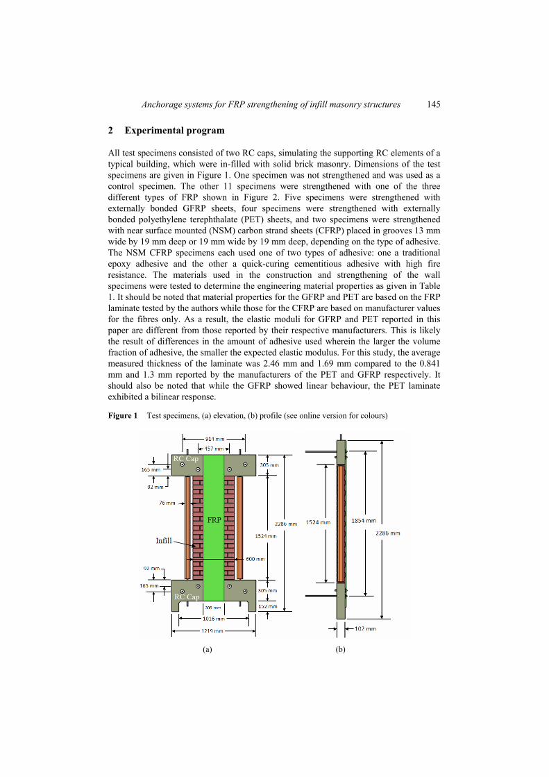
All test specimens consisted of two RC caps, simulating the supporting RC elements of a typical building, which were in-filled with solid brick masonry. Dimensions of the test specimens are given in Figure 1. One specimen was not strengthened and was used as a control specimen. The other 11 specimens were strengthened with one of the three different types of FRP shown in Figure 2. Five specimens were strengthened with externally bonded GFRP sheets, four specimens were strengthened with externally bonded polyethylene terephthalate (PET) sheets, and two specimens were strengthened with near surface mounted (NSM) carbon strand sheets (CFRP) placed in grooves 13 mm wide by 19 mm deep or 19 mm wide by 19 mm deep, depending on the type of adhesive. The NSM CFRP specimens each used one of two types of adhesive: one a traditional epoxy adhesive and the other a quick-curing cementitious adhesive with high fire resistance. The materials used in the construction and strengthening of the wall specimens were tested to determine the engineering material properties as given in Table 1. It should be noted that material properties for the GFRP and PET are based on the FRP laminate tested by the authors while those for the CFRP are based on manufacturer values for the fibres only. As a result, the elastic moduli for GFRP and PET reported in this paper are different from those reported by their respective manufacturers. This is likely the result of differences in the amount of adhesive used wherein the larger the volume fraction of adhesive, the smaller the expected elastic modulus. For this study, the average measured thickness of the laminate was 2.46 mm and 1.69 mm compared to the 0.841 mm and 1.3 mm reported by the manufacturers of the PET and GFRP respectively. It should also be noted that while the GFRP showed linear behaviour, the PET laminate exhibited a bilinear response.
Figure 1 Test specimens, (a) elevation, (b) profile (see online version for colours)
(a) (b)

146 D.S. Lunn et al.
Figure 2 FRP types, (a) GFRP, (b) PET, (c) CFRP (see online version for colours)
(a) (b) (c)
Table 1 Summary of tested material properties
Material Property* ASTM standard Average value**
Concrete fc C39 77.0 MPa Concrete fc C39 (34.4 Mpa) Masonry fm C1314 12.8 Mpa Masonry fm C1314 (22.5 Mpa) Brick fb C140 29.4 Mpa Brick fb C140 (36.1 Mpa) Mortar fj C109 8.7 Mpa Mortar fj C109 (10.6 Mpa) GFRP Ef D3039 16,775 Mpa GFRP εfu D3039 1.85% GFRP ff D3039 282 Mpa PET Ef D3039 6,996 Mpa PET εft D3039 0.66% PET E’f D3039 2,687 Mpa PET εfu D3039 9.12% PET ff D3039 251 Mpa CFRP Ef D3039 245,000 Mpa*** CFRP ff D3039 3,400 Mpa***
Notes: *Properties: fc – concrete uniaxial compressive strength; fm – masonry net compressive strength; fb – brick unit uniaxial compressive strength; fj – mortar uniaxial compressive strength; Ef – FRP tensile chord modulus of elasticity’; εfu – FRP elongation at break (rupture strain); ff – FRP ultimate tensile strength, εft – FRP transition strain, E’f – FRP second tensile modulus of elasticity; **For concrete, cast #2 properties are in parenthesis. For masonry, brick, and mortar round #2 properties are in parenthesis. See Table 2 for correlation of the specimens with the construction phases; ***Values for fibre only as reported by CFRP manufacturer.

Anchorage systems for FRP strengthening of infill masonry structures 147
The six different FRP anchorage systems used are shown in Figure 3. Two specimens (one strengthened with GFRP and one strengthened with PET) were anchored to the RC caps at the top and bottom of the infill with 305 mm of overlap of the FRP onto the RC caps as shown in Figure 3(a). A shear restraint anchorage system consisting of 25 mm thick by 203 mm wide steel plates placed at the top and bottom of the wall and tied to the steel testing frame using steel bolts was used for two specimens strengthened with GFRP and PET respectively as shown in Figure 3(b). Two specimens strengthened with GFRP and PET respectively were anchored using 13 mm diameter CFRP fibre anchors embedded 51 mm into the RC caps as shown in Figure 3(c). The anchorage for one GFRP strengthened specimen consisted of wrapping the FRP sheet around a 10 mm CFRP bar embedded near the surface of the RC cap as shown in Figure 3(d). Two specimens strengthened with GFRP and PET respectively were anchored using pultruded CFRP strips (2 mm thick by 13 mm deep) embedded near the surface of the masonry and RC caps with 152 mm of overlap above and below the masonry/RC interface as shear keys to resist shear sliding as shown in Figure 3(e). The two specimens strengthened with NSM CFRP were anchored to the RC cap by extending the NSM CFRP 305 mm into the RC cap as shown in Figure 3(f).
Figure 3 FRP anchorage systems, (a) overlap, (b) shear restraint, (c) fibre anchor, (d) embedded bar, (e) shear key, (f) NSM overlap (see online version for colours)
Front view Profile view
(a)
Front view Profile view
(b)
Front view Profile view
(c)

148 D.S. Lunn et al.
Figure 3 FRP anchorage systems, (a) overlap, (b) shear restraint, (c) fibre anchor, (d) embedded bar, (e) shear key, (f) NSM overlap (see online version for colours) (continued)
Front view Profile view(d)
Front view Cross-section view (e)
Front view Cross-section view
(f)
The test specimens were loaded out-of-plane with a uniformly distributed pressure to simulate the differential pressure induced by a tornado. An airbag was used to apply static pressure in increasing cycles up to failure. An example of the full loading sequence is given for the GFRP-strengthened specimen with fibre anchors in Figure 4. The airbag was placed within a steel frame between the brick wall and the laboratory reaction wall. The test setup is shown in Figure 5. The laboratory reaction wall is a strong wall fixed to the laboratory strong floor, both of which are extremely rigid compared to the test specimens. The concrete caps were secured to the reaction wall using high strength steel bars (reaction rods) spaced 914 mm on centre. In addition to the four reaction rods, the RC caps were stiffened using four steel bolts centred on the specimen and located at a 457 mm spacing as shown in Figure 6. These bolts were secured only to the steel frame and were not part of the external out-of-plane reaction. This system was used to simulate the out-of-plane rigidity of typical RC buildings. In addition to the out-of-plane rigidity, vertical tie rods were used to simulate the vertical rigidity of RC structures.

Anchorage systems for FRP strengthening of infill masonry structures 149
Figure 4 Typical loading/unloading sequence (see online version for colours)
Figure 5 Test setup (see online version for colours)
Figure 6 Out-of-plane reaction rods and steel bolts (see online version for colours)

150 D.S. Lunn et al.
The applied pressure was measured using a pressure transducer connected to the airbag outflow. In addition to the pressure transducer, a manometer was used to verify the static pressure in the bag. String potentiometers were used to measure the deflection at various locations on the test specimens. These locations were selected to provide the out-of-plane displacement profile of the wall along a vertical line at mid-span, to determine the degree of symmetry in the displacement behaviour, and to determine the slip between the masonry and the RC frame. The typical layout of string potentiometers is shown in Figure 7(a). Electrical resistance strain gages with an electrical resistance of 120 ohms and gage length of 0.25 in. were attached to the outer surface of the FRP sheets in the direction of the fibre orientation to measure the strain during loading. Measuring strain in the FRP sheet identifies the extent to which the FRP is being utilised in resisting the load and provides the locations where debonding is taking place. The typical layout of strain gages is shown in Figure 7(b). A data acquisition system was used to electronically record the data with a frequency of one reading per second.
Figure 7 Typical instrumentation layout, (a) string potentiometers, (b) strain gages (see online version for colours)
(a) (b)
3 Experimental results
The load deflection envelopes for various specimens are shown in Figure 8. The influence of the type of strengthening is illustrated by comparing the strengthened specimens to the unstrengthened control wall. Similarly, the effect of enhanced FRP anchorage is shown by comparing the response of the specimens with various forms of anchorage to those of the corresponding specimens in which anchorage is provided by means of an overlap of the FRP onto the RC caps, which serves as a baseline for strengthened specimens. Figure 8(a) compares the response of specimens strengthened with either GFRP or PET using either shear restraint or overlap anchorage to the response of the unstrengthened (control) wall. It can be seen that the initial stiffness of the

Anchorage systems for FRP strengthening of infill masonry structures 151
strengthened walls was nearly independent of the type of anchorage. However, after initiation of the shear sliding, the stiffness of the overlapped specimens decreased considerably with respect to the corresponding shear restrained specimens. The second slope of the load deflection curve for the shear restrained specimens depended primarily on the type of FRP. It should also be noted that due to the size and shape of the airbag, at the very large deflections observed for the PET shear restrained specimen, (more than 120 mm) the pressure applied to the masonry may not have covered the entire face of the infill wall. The test was continued until the safe operating pressure of the airbag was reached. Thus, the dashed line at displacements greater than 120 mm estimates the load deflection response up to the maximum measured displacement based on the assumption of a constant slope.
The load deflection response of the fibre anchor specimens is compared with those of the overlapped and the control specimens in Figure 8(b). The GFRP fibre anchor specimen had a smaller second stiffness than the corresponding GFRP specimen with overlap. This is consistent with the observation of the initiation of shear sliding and debonding of the GFRP sheet at a lower load level than the corresponding overlapped specimen. This is likely due to variations in construction and material properties which affect the quality of the bed joint and/or the presence of a shrinkage crack at the top interface between the masonry infill and the RC cap. Increase of the applied pressure caused debonding up to the level of the fibre anchors, at which point the response stiffened slightly as the anchors were activated. The PET specimen with fibre anchors had a second stiffness quite close to that of the corresponding overlapped specimen. At an applied pressure of 37 kPa, the fibre anchor specimen experienced a large slip in the range of 20 mm. Before failure, the PET debonded up to the level of the anchors, after which the stiffness increased and the specimen was able to carry additional load.
The load deflection response of the GFRP-strengthened specimen with embedded bar anchorage is compared to the corresponding specimen with overlap and the control in Figure 8(c). The initial stiffness is similar for all three specimens, but the second stiffness of the overlap specimen is greater than that of the specimen with embedded bar anchorage. This is likely the result of variations in construction and material properties which affect the quality of the top bed joint and/or the presence of a shrinkage crack at the top interface between the masonry infill and the RC cap. In a manner similar to the fibre anchor specimen, the embedded bar anchorage specimen experienced debonding up to the level of the embedded bar, at which point the response stiffened as the embedded bar was activated.
Figure 8(d) compares the specimens using shear key anchorage to those with overlap and the control. The initial stiffness is similar for the strengthened specimens, but shear sliding of the overlapped specimens caused a decrease in stiffness relative to the specimens with the shear key anchorage. A reduction in stiffness occurred as the shear keys debonded from the RC caps.
The response of the two NSM specimens each with one of two types of adhesive, cementitious or epoxy are shown in Figure 8(e). Both strengthened specimens showed enhanced stiffness and strength relative to the control. For both, shear sliding began at approximately 20 kPa resulting in the initiation of debonding of the NSM CFRP from the RC caps. This resulted in an initial slip, after which both specimens were able to further resist load until debonding was complete and the specimens collapsed.

152 D.S. Lunn et al.
Figure 8 Load deflection envelopes, (a) shear restraint, (b) fibre anchors, (c) embedded bar, (d) shear key, (e) near-surface mounted (see online version for colours)
(a) (b)
(c) (d)
(e)

Anchorage systems for FRP strengthening of infill masonry structures 153
The displaced shapes (out-of-plane) of the walls and the strain profiles of the FRP sheets along the height of the walls demonstrate the effect of the end anchorage on the behaviour. The out-of-plane displacement profile of the control specimen is characterised by a flexural response in which the largest displacements occur at mid-height and there is very little slip at the top and bottom of the infill as shown in Figure 9(a). It should be noted that in the figure, straight solid lines are used to connect the measured data points which are indicated with open circles. When compared with the displacement profile of the PET-strengthened specimen with overlap anchorage, both have a flexural response, but with the strengthened specimen there is also a large slip (or shear sliding) at the top and bottom of the wall at higher pressures as shown in Figure 9(b). The strain profile of the FRP indicates that it is the shear sliding of the infill out-of-plane at the top and bottom that produces the largest strain. Although a reasonably large strain develops in the FRP at mid-height, it is well below the rupture strain and substantially less than that developed in the FRP at the top and bottom. This is significant because it indicates that the FRP is not reaching its full potential due to premature debonding in the anchorage zone. Enhancing the anchorage, such as by using the steel shear restraint anchorage system can provide a flexural response as observed in both the displacement profile and the strain profile of the GFRP-strengthened specimen as shown in Figure 9(c). The non-zero displacement at the top and bottom of the infill does not indicate sliding of the masonry with respect to the steel, rather it the result of the flexural deformation and rotation of the steel anchorage itself at high load levels. It is clear from the strain profile that shear sliding of the infill is restrained by the steel anchorage and no debonding of the FRP occurs in the anchorage zone. Instead, with the steel anchorage, the FRP is allowed to achieve its full rupture strain, which greatly enhances the load carrying capacity. Other designs of end anchorage did not prevent the shear sliding mechanism, but were successful in increasing the load carrying capacity well beyond that of the initial shear sliding. The displacement and strain profiles of the GFRP-strengthened specimen with the CFRP fibre anchors are shown in Figure 9(d). At an applied pressure near 11.7 kPa, significant shear sliding begins. This initiates debonding of the FRP which gradually propagates towards the level of the anchors, reaching the anchors at an applied pressure of approximately 33.1 kPa. Beyond this, the response stiffens as the anchors engage and an additional 27.6 kPa (60.7 kPa total) of applied pressure is achieved prior to failure. This compares favourably with the corresponding GFRP-strengthened specimen with overlap, which fails at an ultimate applied pressure of 36.1 kPa.
The observed mode of failure depended heavily on the type of FRP anchorage that was used. For many of the specimens, failure initiated in the anchorage zone with mode I (tension-separation) debonding of the FRP and subsequent debonding or pullout of the anchorage system. In each of these cases, the debonding or pullout was a result of shear sliding out-of-plane of the infill wall with respect to the RC caps. The distinction between mode I (tension-separation) debonding, which was frequently observed in this experimental program, and mode II (shear-slip) debonding, which is the basis of most design guidelines for FRP strengthening (e.g., ACI Committee 440, 2010), is shown in Figure 10.

154 D.S. Lunn et al.
Figure 9 Out-of-plane displacement and FRP strain profiles, (a) control specimen, (b) GFRP-strengthened specimen with overlap anchorage, (c) GFRP-strengthened specimen with shear restraint anchorage, (d) GFRP-strengthened specimen with fibre anchors (see online version for colours)
(a)
(b)
(c)
(d)

Anchorage systems for FRP strengthening of infill masonry structures 155
Figure 10 Mode I and mode II debonding in masonry infills (see online version for colours)
The control specimen collapsed due to the formation of a horizontal crack at a bed joint two courses below midspan as shown in Figure 11(a). As this crack grew, it split the wall into two panels which then rotated about the top and bottom supports respectively.
In the case of the specimen strengthened with GFRP and restrained using the steel shear restraint anchorage, the GFRP began to rupture one course above mid-span. This rupture quickly propagated along the width of the strip, as shown in Figure 11(b), resulting in collapse of the wall. The shear restrained PET specimen was also characterised by a flexural response, but was not loaded to ultimate failure because of a limitation of the airbag. Mode II (shear-slip) debonding occurred for this specimen near the region of maximum moment. This debonding did not result in collapse because the wall was physically restrained by the PET which remained anchored at the top and bottom of the wall throughout the test.
Both specimens strengthened with the NSM CFRP failed due to debonding of the CFRP from the RC cap. The debonding initiated at the interface between the top RC cap and the masonry infill and propagated up the cap, as shown in Figure 11(c), until the NSM CFRP was fully debonded after which the wall collapsed. Similarly, the walls using externally bonded FRP with overlap anchorage experienced debonding at the level of the interface between the RC caps and the masonry which propagated along the cap as shown in Figure 11(d).
The shear key specimens failed by debonding of the shear keys from the RC cap. Figure 11(e) shows the underside of the GFRP sheet after testing. This photograph reveals that the bond of the GFRP sheet and the CFRP shear keys to the masonry and RC caps was sufficient since the debonding failure plane was through the masonry and the concrete rather than through the epoxy or at the interface between the epoxy and the substrate.
The specimens strengthened with fibre anchors failed when the anchors pulled out of the RC caps. Figure 11(f) and Figure 11(g) show the PET specimen with fibre anchors just before failure and the underside of the PET sheet after failure respectively. Figure 11(f) clearly shows the shear sliding of the masonry infill which results in the peeling of the PET sheet up to the level of the fibre anchors. Figure 11(g) illustrates the pullout of the fibre anchors and shows that the bond between the anchors and the PET remained intact throughout the testing. It should be noted that the anchorage relied entirely on this bond, as the PET sheet was placed on top of the anchors, rather than cutting a hole and passing the fibre anchors through the PET.

156 D.S. Lunn et al.
Figure 11 Failure modes, (a) flexural, (b) FRP rupture, (c) debonding of NSM CFRP, (d) debonding of GFRP overlap, (e) debonding of shear keys, (f) pullout of fibre anchors, (g) pullout of fibre anchors, (h) debonding of embedded bar, (i) debonding of embedded bar (see online version for colours)
(a) (b) (c)
(d) (e)
(f) (g)
(h) (i)

Anchorage systems for FRP strengthening of infill masonry structures 157
The specimen utilising the embedded bar anchorage failed when the bar debonded from the RC cap as shown in Figures 11(h) and 11(i). In a manner similar to the fibre anchor specimens, the GFRP debonded up to the level of the embedded bar as shown in Figure 11(h). Collapse then occurred when the embedded bar debonded from the RC cap. Figure 11(i) shows the underside of the GFRP sheet after failure and the strong bond achieved between the GFRP and the masonry. Table 2 Summary of experimental results
Ultimate applied pressure
Displacement at ultimate Anchor type FRP type* Constr. phase:
cast # (Round)** (kPa) (mm)
N/A N/A 2 (2) 15.5 36.1 Overlap GFRP 1 (1) 36.1 22.1 Overlap PET 1 (1) 29.3 37.8 Shear restraint GFRP 2 (2) 112.3 60.2 Shear restraint PET 2 (2) ≥ 96.5 ≥ 162.3 Fibre anchor GFRP 2 (2) 60.7 53.8 Fibre anchor PET 2 (2) 50.4 121.7 Embedded bar GFRP 2 (2) 68.3 64.8 Shear key GFRP 1 (2) 56.1 39.6 Shear key PET 1 (2) 38.3 33.0 NSM overlap CFRP-E 2 (2) 25.0 23.9 NSM overlap CFRP-C 2 (2) 36.6 30.5
Notes: *FRP types: GFRP – glass fibre; PET – polyethylene terephthalate fibre; CFRP – E – carbon fibre with epoxy adhesive; CFRP – C – carbon fibre with cementitious adhesive; **Construction phases: for RC caps, there were two casts and for masonry, there were two rounds of construction. See Table 1 for material properties corresponding to the various phases.
A summary of the experimental results is provided in Table 2. In all cases tested, strengthening lead to an increase in the load carrying capacity as shown in Figure 12(a), which is normalised with respect to the control specimen. The amount of this increase ranged between 1.6 and 7.2 times the capacity of the control specimen and was highly dependent on the FRP type and the anchorage system. The largest increase in strength was provided by the steel shear restraint anchorage, which shifted the failure mode from debonding in the anchorage region to rupture of the FRP in the region of maximum moment. The results suggest that the shear key, fibre anchor, and embedded bar are all effective anchorage systems in comparison to the case of overlap only. The load carrying capacity of the walls strengthened with these systems ranged between 31% and 89% greater than that of the corresponding overlapped specimens and between 2.5 and 4.4 times the capacity of the control, which is likely to be adequate for most strengthening applications.
Displacement capacity is also of great interest for extreme loading events, especially in cases where significant energy dissipation is required. Displacement of the strengthened walls at the ultimate pressure ranged from 0.6 to 4.5 times the

158 D.S. Lunn et al.
corresponding displacement of the control specimen as shown in Figure 12(b). The greatest increase in displacement capacity was provided by two PET strengthened specimens, one with fibre anchors and the other with the steel shear restraint anchorage. The displacement capacity for both specimens was well over three times that of the control specimen. This amounts to displacements in excess of 120 mm as shown in Figure 13, which is not possible for 92 mm wide URM walls without strengthening. Thus, in cases where a large displacement capacity is required, it is recommended to use an FRP such as PET that has a high fracturing strain with an anchorage system such as fibre anchors that is able to withstand additional loading even after some shear sliding has occurred.
Figure 12 Ultimate strength and displacement normalised with respect to the control specimen, (a) ultimate strength, (b) displacement at ultimate strength (see online version for colours)
(a) (b)
Figure 13 Displaced shape of PET specimen with shear restraint, (a) profile view, (b) perspective view (see online version for colours)
(a) (b)
Anchorage systems for FRP strengthening of infill masonry structures 159
4 Conclusions
FRP-strengthened masonry infills have been shown to be vulnerable to mode I (tension-separation) debonding of the FRP in the anchorage region as a result of shear sliding along the interface between the masonry infill and the supporting elements. The proposed anchorage systems succeeded in delaying and/or preventing this type of debonding substantially improving the out-of-plane load carrying capacity. The amount of this increase ranged between 1.6 and 7.2 times the capacity of the control specimen and was highly dependent on the FRP type and the anchorage system. The results suggest that the shear key, fibre anchor, and embedded bar are all effective anchorage systems in comparison to the case of overlap only. The displacement capacity was also enhanced in several cases with displacement of the strengthened walls at the ultimate pressure ranging from 0.6 to 4.5 times the corresponding displacement of the control specimen. The PET strengthening system with high fracturing strain provided the largest increase in displacement capacity.
Acknowledgements
The authors gratefully acknowledge the NSF I/UCRC Centre for Integration of Composites into Infrastructure. The authors would especially like to thank Fyfe Company, LLC, Nippon Steel Materials Co., Ltd., Grancrete, Inc. and Maeda Kosen Co. Ltd. for their support.
References ACI committee 440 (2010) ‘Guide for the design and construction of externally bonded FRP
systems for strengthening unreinforced masonry structures (ACI 440.7R-10)’, American Concrete Institute, Farmington Hills, Michigan, USA, 46pp.
Altin, S., Anil, O., Kara, M.E. and Kaya, M. (2008) ‘An experimental study on strengthening of masonry infilled RC frames using diagonal CFRP strips’, Composites Part B: Engineering, Vol. 39, No. 4, pp.680–693.
ASTM standard C109/C109M (2011) ‘Standard test method for compressive strength of hydraulic cement mortars (Using 2-in. or [50-mm] Cube Specimens)’, ASTM International, West Conshohocken, PA, available at http://www.astm.org, DOI: 10.1520/C0109_C0109M-11A.
ASTM standard C1314 (2011) ‘Standard test method for compressive strength of masonry prisms’, ASTM International, West Conshohocken, PA, available at http://www.astm.org, DOI: 10.1520/C1314-11.
ASTM standard C140 (2011) ‘Standard test method for sampling and testing concrete masonry units and related units’, ASTM International, West Conshohocken, PA, available at http://www.astm.org, DOI: 10.1520/C0140-11A.
ASTM standard C39/C39M (2011) ‘Standard test method for compressive strength of cylindrical concrete specimens’, ASTM International, West Conshohocken, PA, available at http://www.astm.org, DOI: 10.1520/C0039_C0039M-11A.
ASTM standard D3039/D3039M (2008) ‘Standard test method for tensile properties of polymer matrix composite materials’, ASTM International, West Conshohocken, PA, available at http://www.astm.org, DOI: 10.1520/C0109_C0109M-11A.

160 D.S. Lunn et al.
Bajpai, K. and Duthinh, D. (2003) ‘Bending performance of masonry walls strengthened with near-surface mounted FRP bars’, Proceedings of the Ninth North American Masonry Conference, Clemson, South Carolina, USA, pp.1052–1063.
Carney, P. and Myers, J.J. (2003) ‘Shear and flexural strengthening of masonry infill walls with FRP for extreme out-of-plane loading’, Proceedings of the Architectural Engineering Institute 2003 Annual Meeting, Austin, Texas, USA, pp.246–250.
Galati, N., Tumialan, G. and Nanni, A. (2006) ‘Strengthening with FRP bars of URM walls Subject to out-of-plane loads’, Construction and Building Materials, Vol. 20, Nos. 1–2, pp.101–110.
Hamilton, III, H.R. and Dolan, C. (2001) ‘Flexural capacity of glass FRP strengthened concrete masonry walls’, Journal of Composites for Construction, Vol. 5, No. 3, pp.170–178.
Hamoush, S.A., McGinley, M.W., Mlakar, P., Scott, D. and Murray, K. (2001) ‘Out-of-plane strengthening of masonry walls with reinforced composites’, Journal of Composites for Construction, Vol. 5 No. 3, pp.139–145.
Kuzik, M.D., Elwi, A.E. and Cheng, J.J.R. (2003) ‘Cyclic flexural tests of masonry walls reinforced with glass fiber reinforced polymer sheets’, Journal of Composites for Construction, Vol. 7, No. 1, pp.20–30.
Lunn, D.S. and Rizkalla, S.H. (2011) ‘Strengthening of infill masonry walls with FRP materials’, Journal of Composites for Construction, Vol. 15, No. 2, pp.206–214.
Patoary, M.K.H. and Tan, K.H. (2003) ‘Blast resistance of prototype in-built masonry walls strengthened with FRP systems’, Proceedings of the 6th International Symposium On FRP Reinforcement for Concrete Structures (FRPRCS-6), World Scientific, Singapore, pp.1189–1198.
Tan, K.H. and Patoary, M.K.H. (2004) ‘Strengthening of masonry walls against out-of-plane loads using fiber-reinforced polymer reinforcement’, Journal of Composites for Construction, Vol. 8, No. 1, pp.79–87.
Triantafillou, T.C. (1998) ‘Strengthening of masonry structures using epoxy-bonded FRP laminates’, Journal of Composites for Construction, Vol. 2, No. 2, pp.96–104.
Velazquez-Dimas, J.I. and Ehsani, M.R. (2000) ‘Modeling out-of-plane behaviour of URM walls retrofitted with fiber composites’, Journal of Composites for Construction, Vol. 4, No. 4, pp.172–181.