Anchorage in Orthodontics
123
-
Upload
nadiah-sulaiman -
Category
Documents
-
view
961 -
download
51
Transcript of Anchorage in Orthodontics
● Concept● Definition & Classification● Consideration of anchorage in three planes of
space● Anchorage planning (Methods to increase
anchorage potential)● Tweeds concept of anchorage preparation● Anchorage considerations with Begg● Anchorage considerations with PEA● Anchorage demand- minimum, moderate ,
maximum● Implants as a source of anchorage
● Whenever a force is applied the stabilized site from where the force is exerted is the anchorage
● Tug of war- ● Two equal sized people will pull each other together by an
equal amount.● A big person will pull a small one without being moved.● If two or more smaller person combine the chances of
pulling a big person will increase.
● The pegs/ stakes driven into the ground at an angle to support the tent
● The stakes are at an angle that the pull of the tent ropes against the stake would not increase 90˚
● The stakes driven too vertically will be pulled upward & towards the tent.
● Newton & his laws of motion:● Law I: A thing at rest or in motion continues to do
so unless acted upon by an external force● Law III : Every action has an equal & opposite
reaction
● We know that to create movement / displacement, we must have a force acting on the body.
● For eg. Body (B) is at rest. Lets apply a force (F) to move it to the left. The force (F) will have to overcome the frictional force( Fr) bw the body (b) & the surface (S), the gravitational force (G), only then a particular movement will be seen.
● If the force (F) is smaller in magnitude than the sum (Fr+G), then no movement will take place.
● For every kind of movement there exist an optimal force level, below which that particular movement cannot be produced.
● So this force level is the anchorage potential of the body (B) for that particular movement
● Let us now come to oral cavity & teeth.● If an upper canine is to be retracted, with bodily
movement using a fixed appliance, the force applied to the canine is approx. 100 gm.
● Forces in the opp. direction varying from 67 gm on the 1st molar to 33gm on the upper 2nd PM resist this.
● Minimum unwanted anterior movement of the posterior teeth.
● As the force level is increased to 300g the reciprocal forces also increases with greater risk of mesial movt. of post teeth.
● The anchorage value of any tooth is roughly equivalent to its root surface area
Relationship of tooth movt. To force
● An obvious strategy for anchorage control is to concentrate the force needed to produce tooth movt where it is desired, & to dissipate the reaction force to as many other teeth as possible, keeping the pressure in pdl of anchor teeth as low as possible.
● Pressure in Pdl is determined by f/a.
● Tooth movt increases as pressure increases up to a point, remains at the same level up to a broader range, & then may actually decline with extremely heavy pressure.
● The optimum force for orthodontic tooth movement is the lightest force that produces a maximum or near maximum response (i.e, which brings pressure in the PDL to the edge of the nearly constant portion of the response curve).
● Forces greater than that , though equally effective in producing tooth movement, would be unnecessarily traumatic & stressful to the anchorage
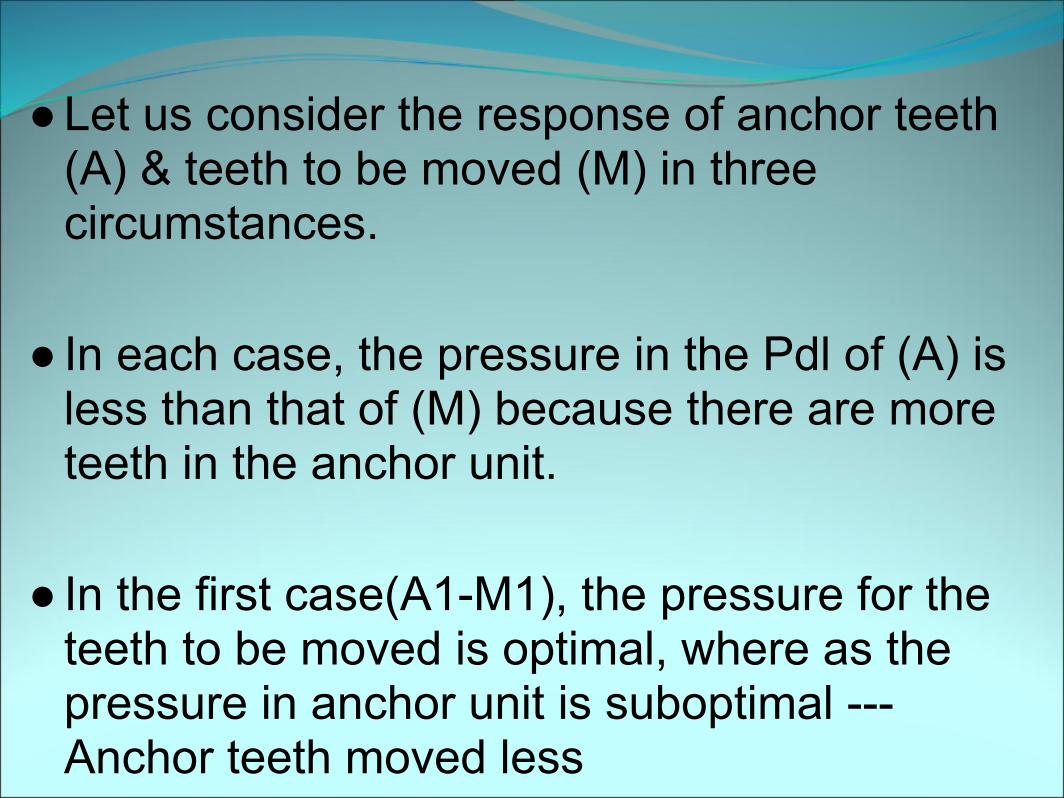
● Let us consider the response of anchor teeth (A) & teeth to be moved (M) in three circumstances.
● In each case, the pressure in the Pdl of (A) is less than that of (M) because there are more teeth in the anchor unit.
● In the first case(A1-M1), the pressure for the teeth to be moved is optimal, where as the pressure in anchor unit is suboptimal --- Anchor teeth moved less
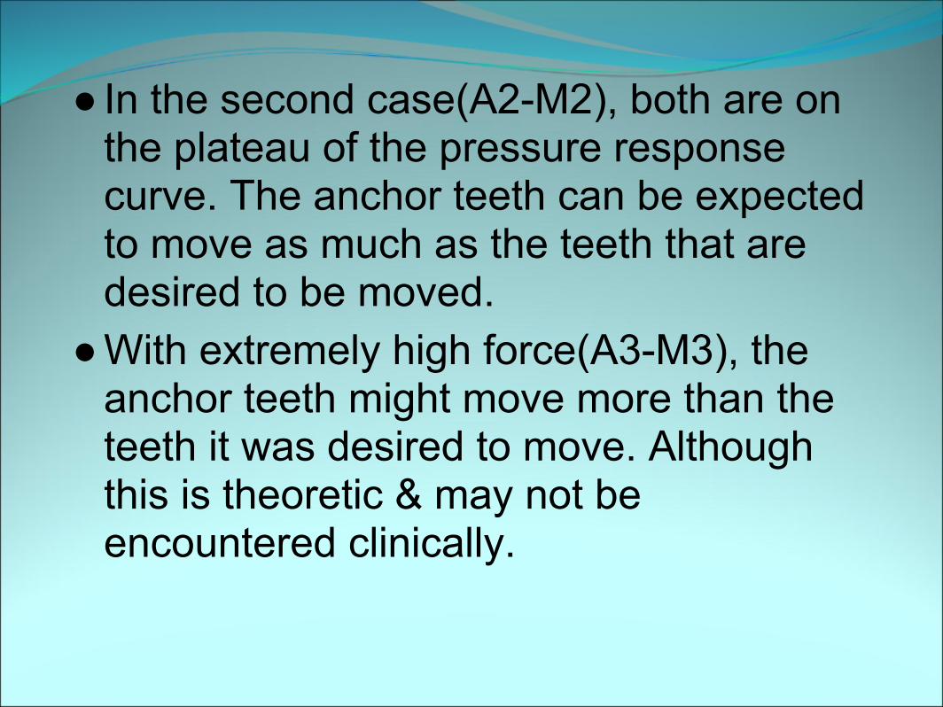
● In the second case(A2-M2), both are on the plateau of the pressure response curve. The anchor teeth can be expected to move as much as the teeth that are desired to be moved.
● With extremely high force(A3-M3), the anchor teeth might move more than the teeth it was desired to move. Although this is theoretic & may not be encountered clinically.
Defination● The term Anchorage in orthodontics refers to the
nature & degree of resistance to displacement offered by an anatomic unit when used for the purpose of effecting tooth movement
Classification● 1. According to manner of force application● 2. Acc. To jaws involved● 3. Based on site of anchorage● 4. Based on no. of anchorage units.
Manner of force application
● I. Simple Anchorage● 2. Stationary Anchorage● 3. Reciprocal Anchorage
Simple Anchorage● Dental anchorage in which manner & application of
force tends to change the axial inclination of the tooth or teeth that form the anchorage unit in the plane of space in which the force is being applied.
● Resistance of the anchorage unit to tipping is utilized to move another tooth or teeth.
Factors important for assessing resistance value of an anchorage unit( tooth)
● The part of tooth which is anchored in the alveolar bone
● No. of roots● Shape, size & length of each root– A
triangular shaped root offers greater resistance to movement than a conical or ovoid shaped root
Or it can also be expressed as the approximate root surface area.A tooth with a larger R.S.A is more resistant to displacement than one with a smaller R.S.A
Other factors are also involved such as -- Relation of contiguous teeth-- the forces of occlusion--The age of pt--individual tissue response variables
● It is also imp. to check inclined plane relationships & muscular forces in assessing value of an anchorage unit.
● Amt. of force used is also imp. The forces should be below the threshold needed for movt. of post. teeth while serving light forces against the ant. teeth.
Stationary Anchorage● Dental anchorage in which manner & application of force tends to displace the anchorage unit bodily in the plane of space in which the force is being applied is termed Stationary anchorage.
● Anchorage provided by a tooth which is resisting bodily movt. Is considerably greater than one resisting tipping force
● This refers to the advantage that can be obtained by pitting bodily movement of one gp. of teeth against tipping of another.
● For eg. If the appliance were arranged so that the anterior teeth could tip lingualy while the posterior teeth could only move bodily, the optimum pressure for the anterior segment would be produced by abt. 1/2 as much force as if the anterior would be to be retracted bodily.
● This would mean that the reaction over the post teeth would be reduced by ½, so these teeth would move ½ as much.
Reciprocal Anchorage● Refers to resistance offered by two malposed units
when the dissipation of equal & opp. forces tends to move each unit towards a more normal occlusion.
● Two teeth or two gp. of teeth of equal anchorage value are made to move in opp. direction.
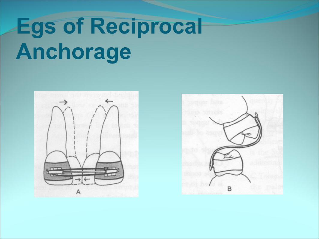
Egs of Reciprocal Anchorage
Site of anchorage ● Intraoral Anchorage ● Teeth● Alveolar bone● Basal bone● musculature
● Extra oral Anchorage● Cranium (occipital or
parietal anchorage)● Back of neck (Cervical
anchorage● Facial bones
● classification……
According to jaws involved● Intramaxillary Anchorage
● All the resistance units are situated in the same jaw
● classification……
● Intermaxillary Anchorage● Anchorage in which resistance units
situated in one jaw are used to effect tooth movement in the opposing jaw.
● Also termed Baker’s anchorage
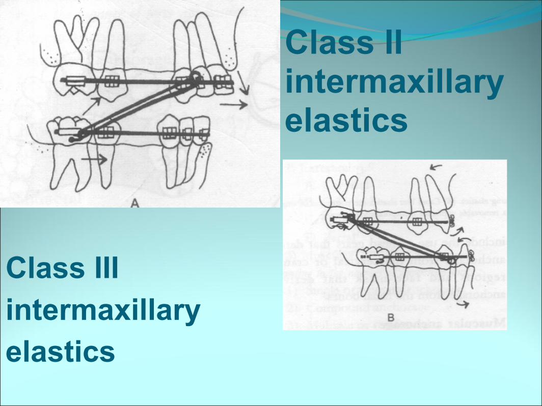
Class II intermaxillary elastics
Class III intermaxillary elastics
Based on no. of anchorage units● Single or primary anchorage● Cases wherein the resistance provided by
a single tooth with greater alveolar support is used to move another tooth with less support
● classification……
● Compound Anchorage● Here the resistance provided by more
than one tooth with greater support is used to move teeth with lesser support
Multiple / Reinforced Anchorage
● More than one type of resistance unit is utilized● Refers to augmentation of anchorage by various
means● -- extraoral forces● -- adding 2nd molars to the post unit to augment
post achorage● --Traspalatal arch
Three Dimensional Anchorage evaluation
● Considering anchorage in all the three planes (sagittal, vertical & transverse)
● And subsequent anchorage planning is very important before initiating any tooth movements.
● Horizontal anchorage control means limiting the mesial movt. Of post. Segment while encouraging distal movt. Of ant. Segments.
● For example, a "maximum anchorage Class II, division 1 case" is one in which no forward movement of the upper posterior segments is allowed, but preparation is made for maximum retraction of the upper anterior segment.
● Vertical anchorage control involves limitation of the vertical skeletal & dental development in the post. Segments & the limitation of the vertical eruption or even intrusion of the ant. Segment.
● In the transverse plane, it comprises of maintenance of expansion procedures & the avoidance of tipping or extrusion of posterior teeth during expansion.
ANCHORAGE PLANNING
Methods to increase anchorage potential
● I . By increasing the resistance to displacement
● II. By decreasing the displacement potential
Increasing the resistance to displacement● 1. Increase the no. of teeth in the anchorage
unit ( increase root surface area)● 2.Create Buccal segments
The post. teeth are connected by rigid sectional arch wire(18×25, 19×25).Alternatively, in the absence of brackets a rigid sectional arch wire can be bonded to the teeth, to create a buccal segment which acts like a large multirooted tooth generating good post. anchorage.
Increasing the resistance to displacement…..
● 3. Cortical anchorage● Moving the roots of anchor molar into the
cortex increases their resistance to displacement.
● 4. Palatal , lingual arches , Nance’s button
● The bilateral buccal segments thus connected offer significant benefits.
● Incorporation of anterior vault of palate enhances post. Anchorage.
Increasing the resistance to displacement…
● 5. Extraoral anchorage
● 6. Muscular forces can be used to augment anchorage such as through use of lip bumper
Increasing the resistance to displacement…
● 7. Moments generated through cantilever springs or base intrusion arches are applied to anchor teeth. These create distal tipping forces, which help to resist anterior displacement of anchor units.
● 8. Implants, Ankylosed teeth● They are perfect egs of stationary
anchorage
Decreasing the displacement potential
● 1. Reduce forces● 2. Reduce friction● 3. Sequential loading
● 1. Reduce forces ..movt. In stages● ..using movements which require less force
Decreasing the displacement potential….
● 2. Reduce friction .. Using frictionless mechanics● ..use of optimal clearance bw bracket & arch wire.
0.002 clearance is advocated for using sliding mechanics● … Optimal leveling to reduce binding effect
● 3. Sequential loading …Gradual progression towards stiffer slot filling arch wires
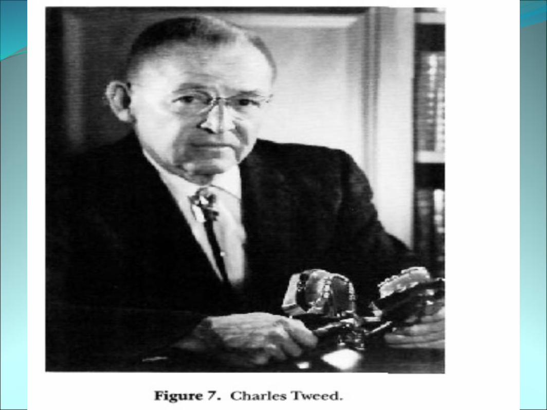
Tweed’s Classification of anchorage● First Degree Anchorage preparation
● It is applicable to all malocclusions with ANB angles ranging from 0˚ to 4˚ in which facial esthetics are good and in which total discrepancy does not exceed 10 mm.
● It is mainly limited o high cuspid, crossbite pseudo-Class III, and true Class III cases.
● The degree to which anchorage should be prepared is minimal.
● Mandibular terminal molars must always be uprighted and / or maintained in such an upright position as to prevent their being elongated when Class II intermaxillary force is used
● As a general rule, this means that the inclination of the mandibular terminal molars should be such that the direction of pull of the intermaxillary elastic force during function will not exceed 90˚ when related to the long axis to these teeth.
● Second degree anchorage preparation
● Indicated when ANB exceeds 4.5˚and facial esthetics make it desirable to move point B anteriorly and point A posteriorly
● .● These cases are usually Class II in nature
and require prolonged Class II intermaxillary mechanics
● They are accompanied by Type A, Type A Subdivision, Type B and Type B subdivision growth trends
● The mandibular terminal molars must be tipped distally so that their distal marginal ridges are at gum level.
● The direction of pull of the Class II elastics when related to the long axes of the terminal molars should be greater than 90˚ during function, so that the terminal molars will be further depressed rather than elongated
● Third degree or total anchorage preparation
● It is necessary in extremely severe malocclusion in which total discrepancy vary from 14 to 20 mm or more but the ANB angle does not exceed 5˚
● Class I in nature, with exceedingly irregular teeth.
● Jigs are necessary for third degree or total anchorage preparation in the mandibular arch.
● In these all three posterior teeth from and including the second PM’s to and including the terminal molars must be tipped distally to anchorage preparation positions
● This means that both second PM’s and first molars must be tipped to such distoaxial inclinations that the distal marginal ridges of the terminal second molars are below gum level
● In such positions, their mesial displacement & elongation will not be great, during the period when prolonged and vigorous intermaxillary force is being used
● Conventionally Begg technique is considered to be kind on to the anchorage & the PEA anchorage taxing
Begg & PEA● Pinning of base arch wire
into anteriors generates powerful posterior anchorage by activating the anchor bend
● Simultaneous aligning, leveling & retraction of U/L anteriors
Anchorage is to be actively created
Discreet phases of aligning
Levelling /& retraction of U/L anteriors, each with its anchorage considerations.
● Movt of ant. Are with torque control which places strain onto the anchorage
● No MD tipping freedom
Movts of ant. are in 2 stages, tipping & uprighting which is kind to the anchorage
Anteriors have the freedom to tip in both LL but importantly mesiodistally.
● Loosing anchorage isa definite & positive decision
● Conserving anchorage is a definite & positive decision
Anchorage considerations with PEA
● Anchorage control in PEA is very imp. Because of the features built in the appliance, which tend to procline the teeth
● Let us examine diff. phases of treatment, & how the anchorage can be controlled.
● McLAUGHLIN & BENNETT ● Defined anchorage control during leveling
and aligning as "the maneuvers used to restrict undesirable changes during the initial phase of treatment, so that leveling and aligning is achieved without key features of the malocclusion becoming worse".
Control of anchorage in the horizontal plane
● Anchorage control in the ant segment
● Anchorage control in the post segment
Anchorage control in the ant segment
In initial wires with preadjusted system,tip built into anterior brackets increases tendency of anterior teeth to tip forward.
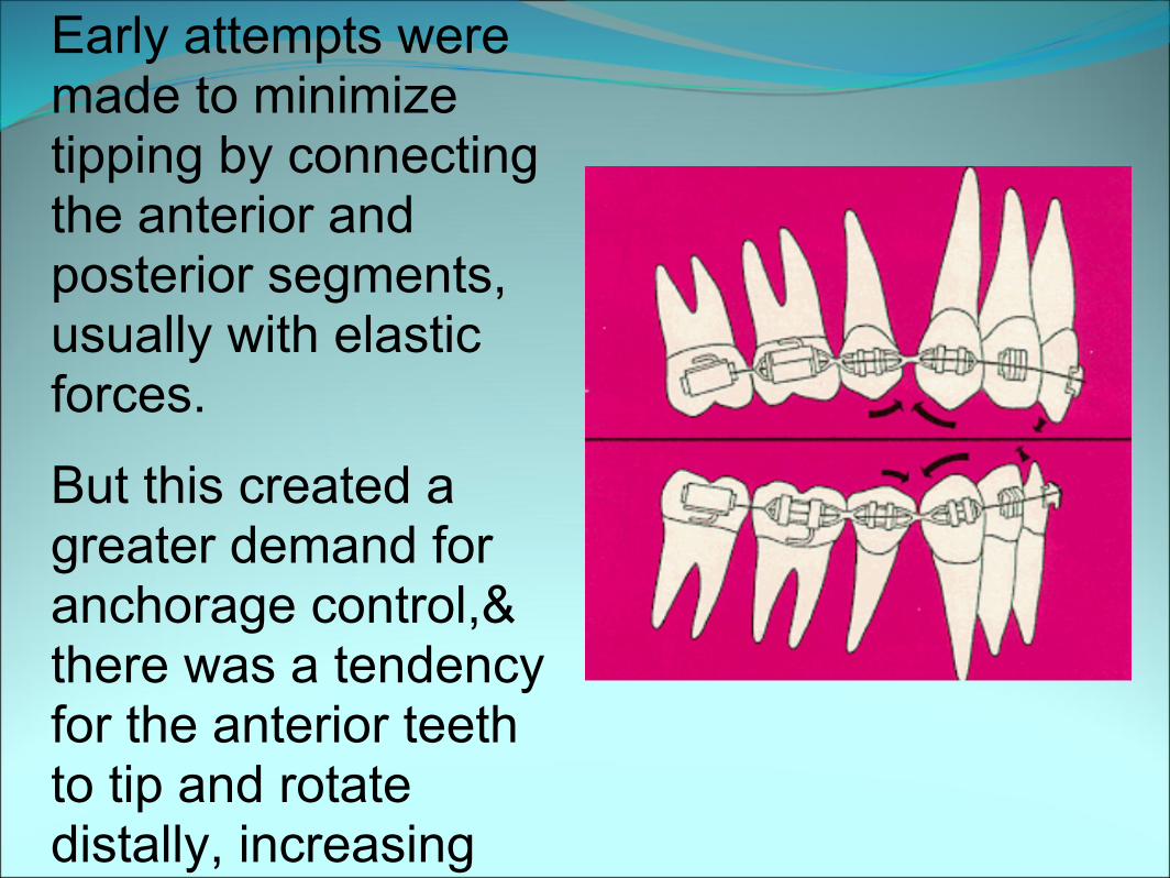
Early attempts were made to minimize tipping by connecting the anterior and posterior segments, usually with elastic forces.
But this created a greater demand for anchorage control,& there was a tendency for the anterior teeth to tip and rotate distally, increasing the curve of Spee and deepening the bite.
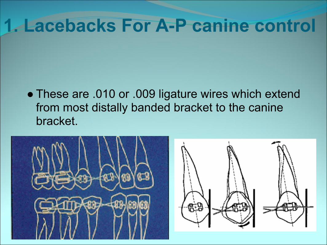
● These are .010 or .009 ligature wires which extend from most distally banded bracket to the canine bracket.
1. Lacebacks For A-P canine control
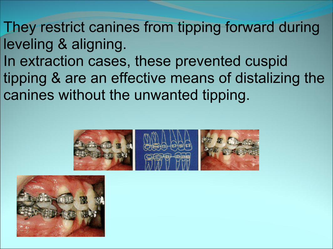
They restrict canines from tipping forward during leveling & aligning.In extraction cases, these prevented cuspid tipping & are an effective means of distalizing the canines without the unwanted tipping.
● Robinson investigated 57 PM Xn cases, ½ of which were treated with lace backs & ½ without.
● His findings confirm that Lower canine lace backs have beneficial effect in controlling lower incisor proclination.
● Without lace backs, the L.I moved forward 1.4 mm, in contrast, with lace backs in place, the L.I moved 1mm distally.
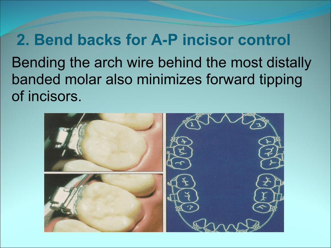
2. Bend backs for A-P incisor controlBending the arch wire behind the most distally banded molar also minimizes forward tipping of incisors.
● Like lacebacks, bendbacks are continued throughout leveling & aligning archwire sequence.
● In cases where it is necessary to increase arch length, & where A-P control is not required, bendbacks should be placed1 or 2 mm distal to molar tubes.
Anchorage control in the post segment● In certain cases, it may be necessary for
the upper post segments to be limited in their mesial movt, maintained in their position or even distalized.
● Headgear● Palatal Bar● Lingual arch● Lip Bumper● Class III elastics
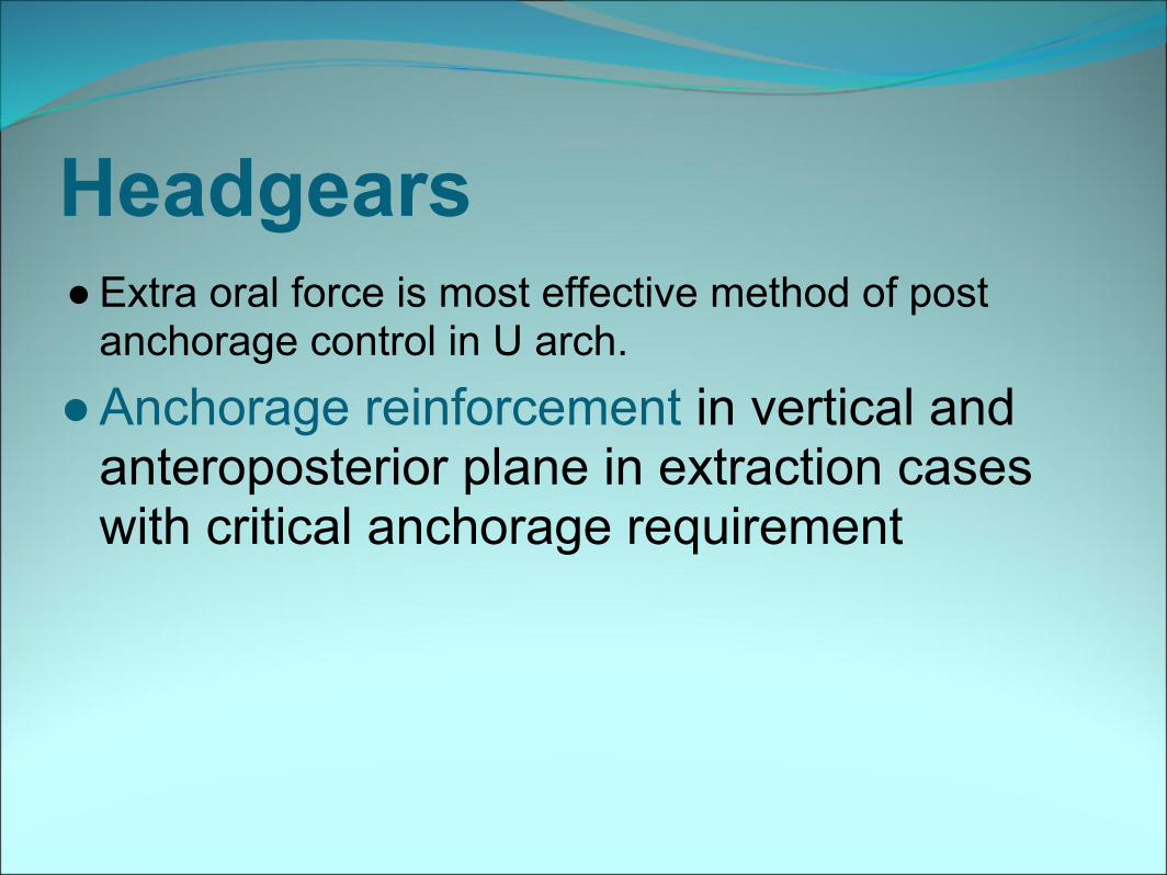
Headgears● Extra oral force is most effective method of post
anchorage control in U arch.● Anchorage reinforcement in vertical and
anteroposterior plane in extraction cases with critical anchorage requirement
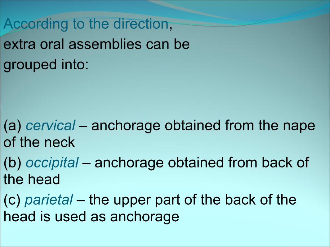
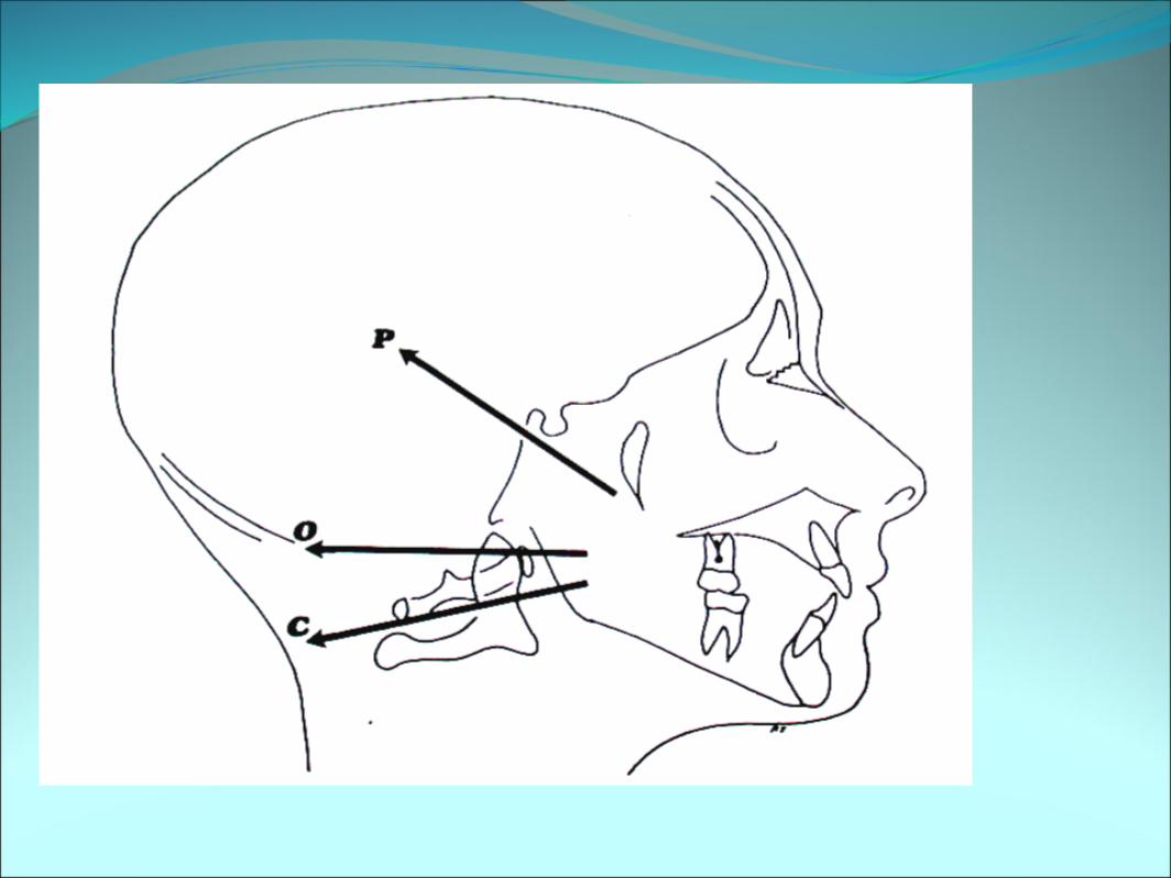
According to the direction,extra oral assemblies can begrouped into:
(a) cervical – anchorage obtained from the nape of the neck(b) occipital – anchorage obtained from back of the head(c) parietal – the upper part of the back of the head is used as anchorage
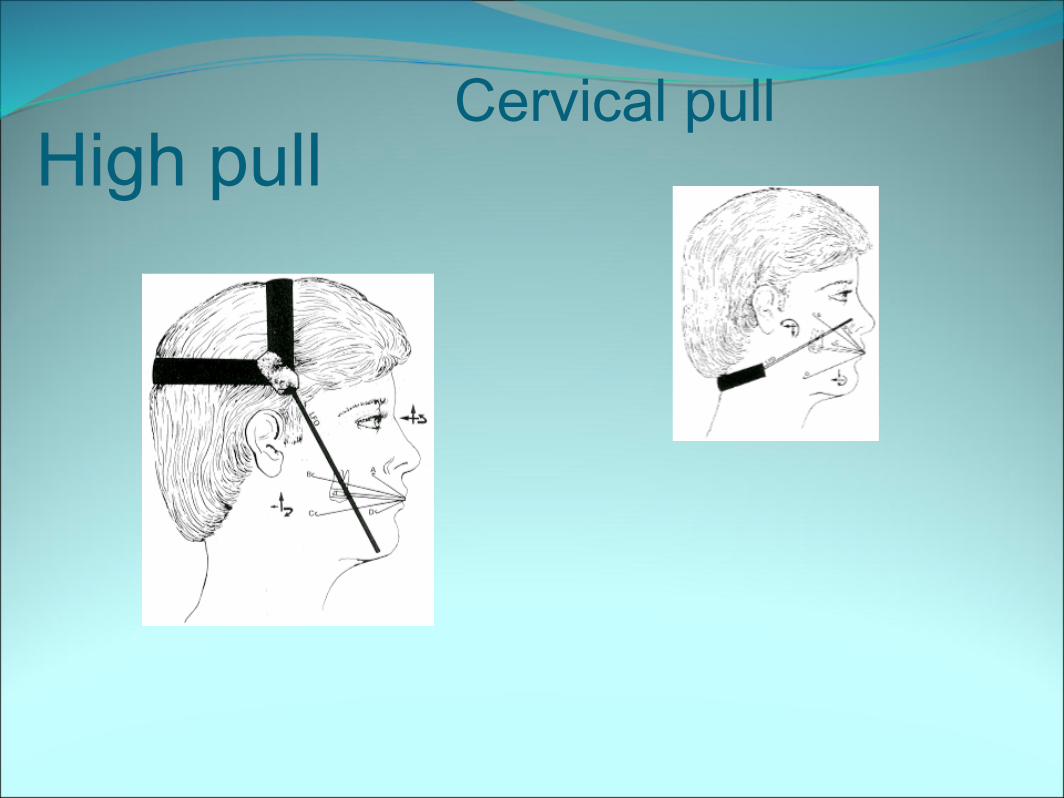
High pullCervical pull
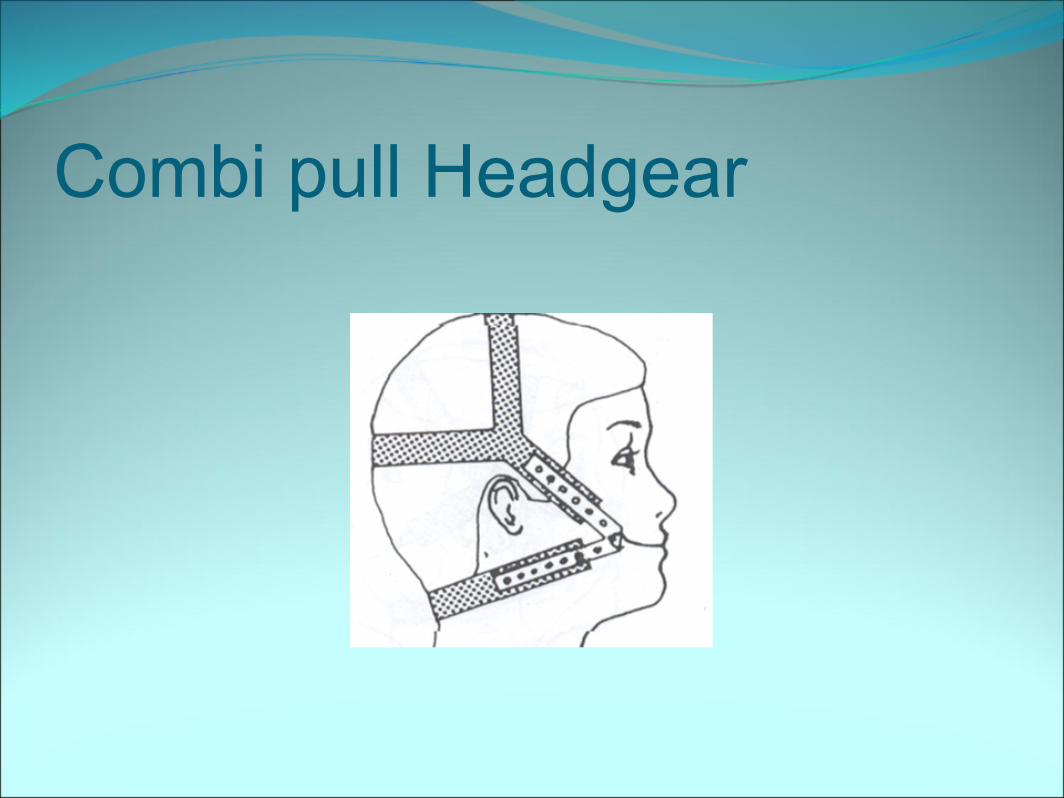
Combi pull Headgear
● If the LF passes below the CR of the tooth, as in cervical traction, an extrusive component of force will be present.
● If it passes above the CR of the tooth then intrusive component of force will be present.
● The combination headgear is useful in most cases.
● It minimizes the tendency for extrusion of upper posterior teeth, While simultaneously allowing effective distalization of the molar
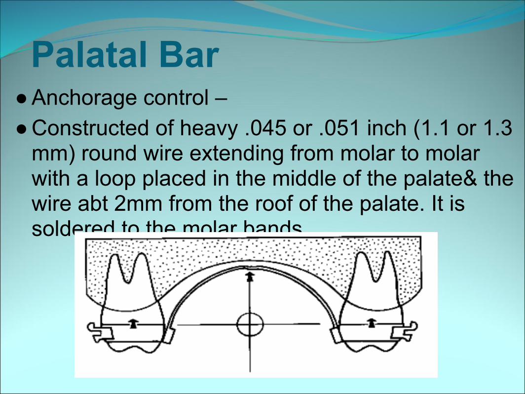
Palatal Bar● Anchorage control –● Constructed of heavy .045 or .051 inch (1.1 or 1.3
mm) round wire extending from molar to molar with a loop placed in the middle of the palate& the wire abt 2mm from the roof of the palate. It is soldered to the molar bands.
The Nance holding arch● It extends from upper molars to the anterior portion of
the palatal vault.● A steep anterior palatal vault has a buttressing effect
so is a useful source of anchorage
Lingual arch● Used as space maintainers● Used for max anchorage PM Xn cases
● It restricts the mesial movt. of the lower molars & ensures that most of the Xn space is available for anterior alignment
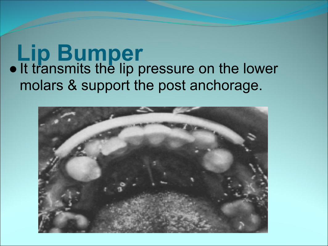
Lip Bumper● It transmits the lip pressure on the lower
molars & support the post anchorage.
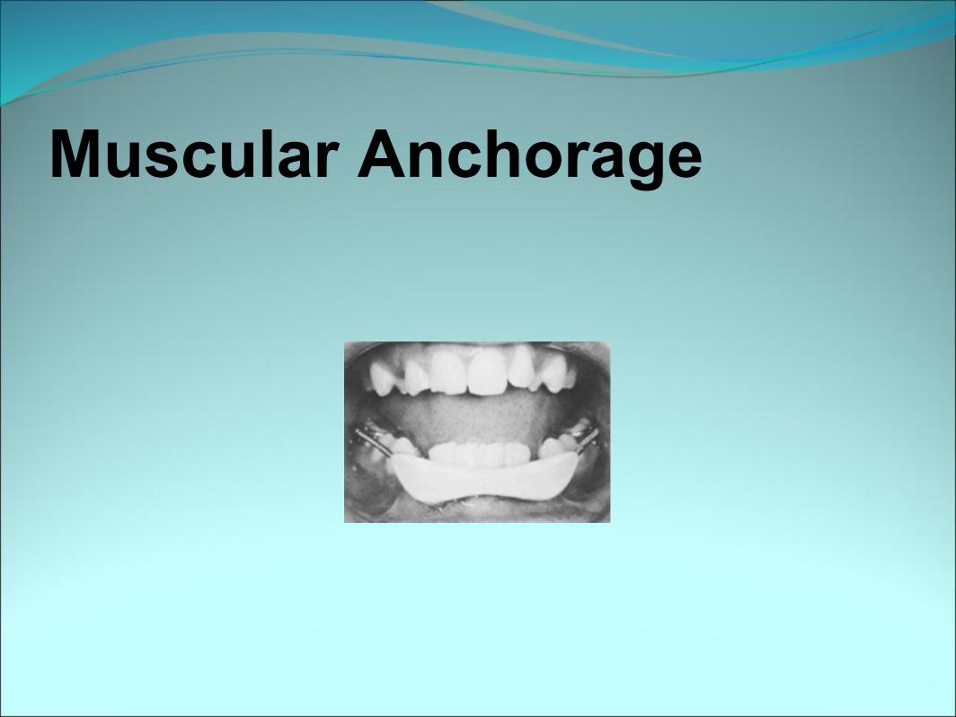
Muscular Anchorage
ClassIII Elastics & headgear
● In cases with severe lower incisor crowding, where more anchorage support is needed that can be provided by a lingual arch alone, Class III elastics can be worn to Kobayashi tiewires in the lower canine region, at the same time as a head gear.
Vertical anchorage control● In case of distally tipped canines, the
incisors may be entirely bypassed, till the canines are uprighted, to prevent deepening of the bite anteriorly.
● It is important to avoid early archwire engagement of high labial canines, so that unwanted vertical movement of laterals & PM does not occur.
● Vertical control of molars in high angle cases
● Upper 2nd molars are usually not initially banded, to minimize extrusion of these teeth.
If they reqire banding an arch wire step can be placed behind the 1st molar to avoid extrusion
● If palatal bars are used, they are designed to lie away from the palate by approx 2mm so that tongue can exert an intrusive force.
● Combination pull or high pull headgears are used. Cervical pull HG is avoided.
● In some cases, U/ L post bite plate in molar region is helpful to minimize extrusion of molars.
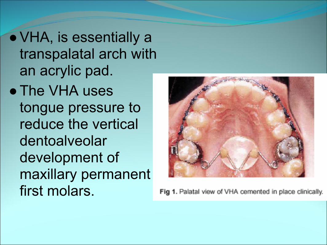
● VHA, is essentially a transpalatal arch with an acrylic pad.
● The VHA uses tongue pressure to reduce the vertical dentoalveolar development of maxillary permanent first molars.
● The VHA was fabricated with banded maxillary permanent first molars connected with a 0.040-inch chrome cobalt wire with a dime-size acrylic button at the sagittal and vertical level of the gingival margin of the molar bands.
● Four helices were incorporated into the wire configuration for flexibility.
● VHA restricts and even helps to reduce the percentage of lower anterior vertical face height.
● Evaluation of the vertical holding appliance in treatment of high-angle patients
● Marcsss DeBerardinis, Tony Stretesky, Pramod Sinha, and Ram S. Nanda, Oklahoma City, Okla,
● AJO 2000, volume 117
Anchorage control in transverse plane● Inter canine width● Maintenance of intercanine width is
important for stability. They should be kept as close as possible to the starting dimensions.
● Molar crossbites● They should be corrected by bodily movt.
Rather than tipping which extrudes the palatal cusps.
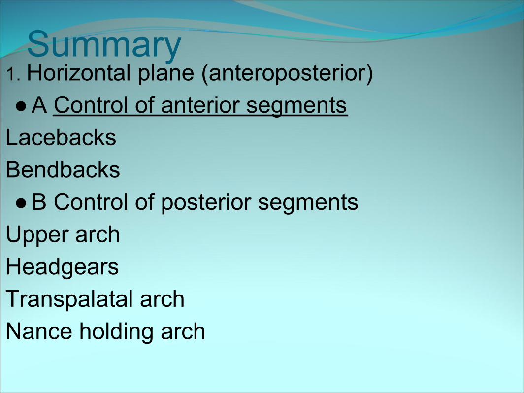
Summary1. Horizontal plane (anteroposterior)● A Control of anterior segments
Lacebacks Bendbacks ● B Control of posterior segments
Upper arch Headgears Transpalatal arch Nance holding arch
Lower arch Lingual arch Class III elastics Lip bumper
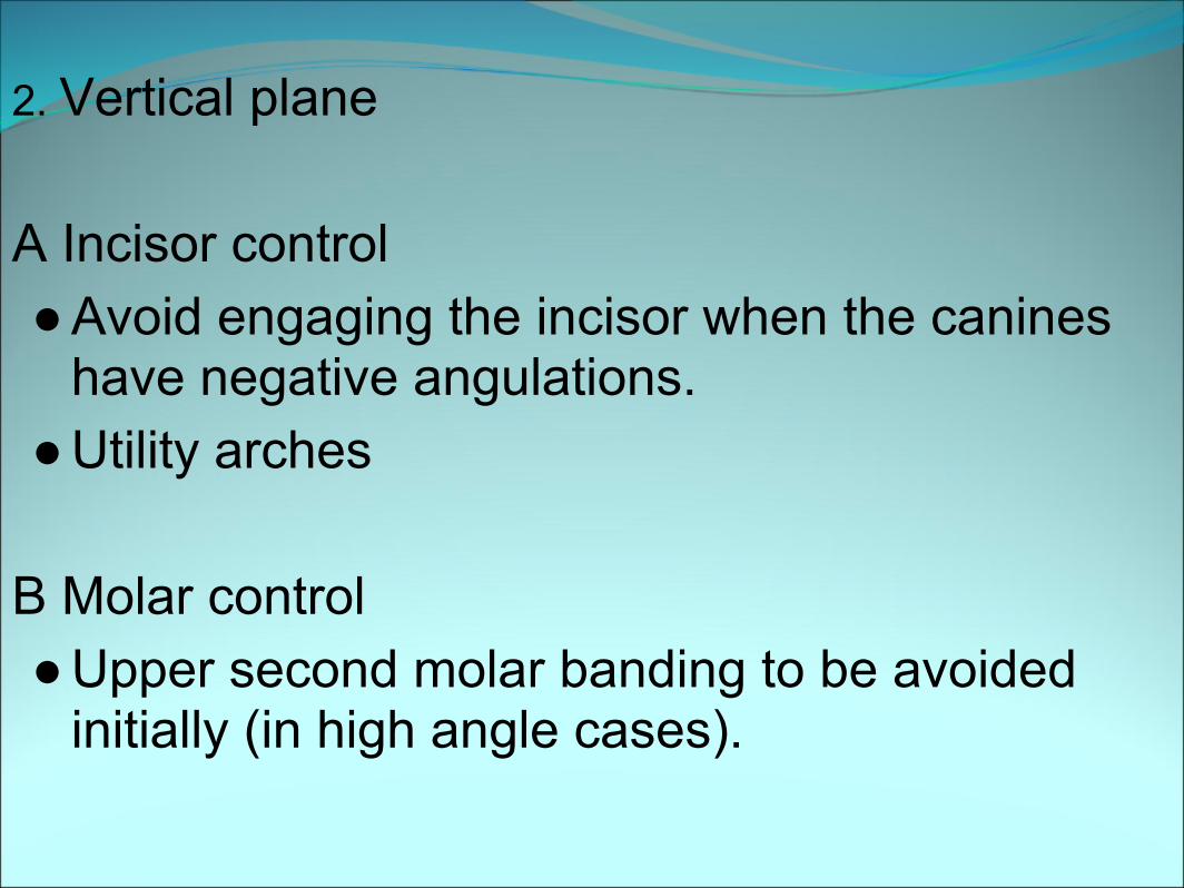
2. Vertical plane
A Incisor control ● Avoid engaging the incisor when the canines
have negative angulations.● Utility arches
B Molar control ● Upper second molar banding to be avoided
initially (in high angle cases).
● Expansion if required should be achieved by bodily movement of the posterior teeth (in high angle cases).
● Transpalatal arch should be 2-3 mm away from the palate.
● High pull or combi pull headgear to be used.● Posterior bite planes or bite blocks
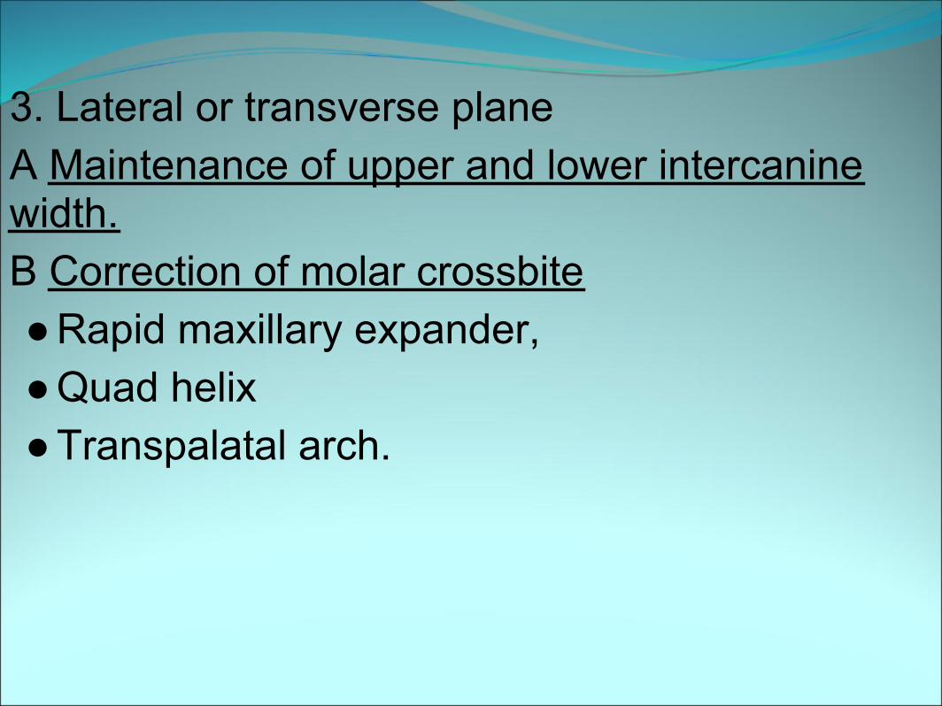
3. Lateral or transverse plane A Maintenance of upper and lower intercanine width. B Correction of molar crossbite ● Rapid maxillary expander,● Quad helix ● Transpalatal arch.
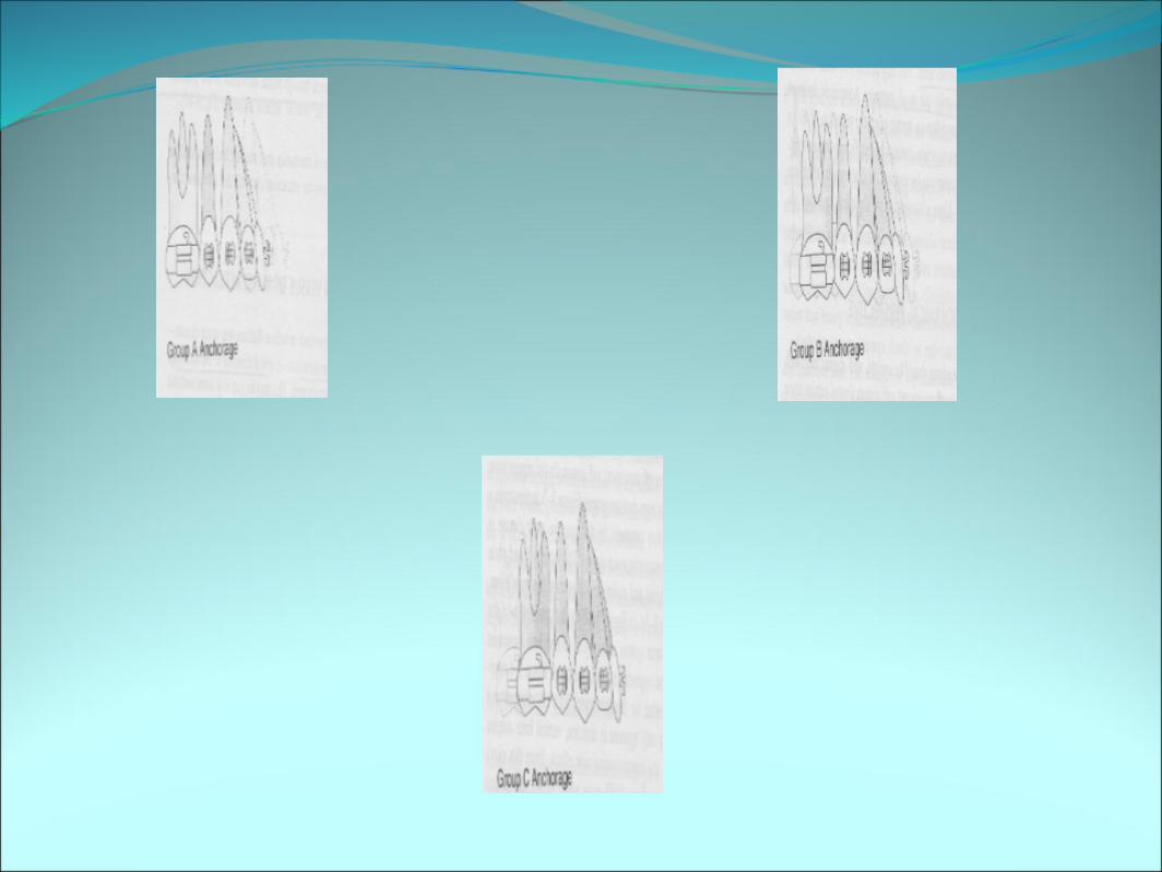
Retraction or space closure● ANCHORAGE CLASSIFICATION ● Anchorage needs of an individual treatment
plan could vary from absolutely no mesial movement of the molars/ premolars permitted (or even distal movement of the molars needed) to 100% of the space closure by mesial protraction of the posterior teeth Anchorage can be classified as:
A Anchorage. This category describes the critical maintenance of the posterior tooth position. Seventy-five percent or more of the extraction space is needed for anterior retraction
B Anchorage This category describes relatively symmetric space closure with equal movement of the posterior and anterior teeth to close the space. This is the least difficult space closure problem
C Anchorage This category describes non critical anchorage. Seventy-five percent or more of the space closure is achieved through mesial movement of the posterior teeth. This could also be considered to be critical anterior anchorage .
COMPONENTS OF FORCE SYSTEM
● Alpha Moment● This is the moment acting on the anterior teeth
(often termed anterior torque).● Beta Moment● This is the moment acting on the posterior
teeth Tip-back bends places mesial to the molars produce an increased beta moment
● Horizontal Forces ● These are the mesio distal forces acting
on the teeth. The distal force acting on the anterior teeth always equal the mesial forces acting on the posterior teeth.
● Vertical Forces● There are intrusive-extrusive forces acting on the anterior
or posterior teeth. These forces generally result unequal alpha and beta moments.
● When the beta moments is greater than the alpha moments, an intrusive forces acts on the anterior teeth, if alpha moment is greater than the beta moment, then extrusive forces act on the anterior teeth while intrusive forces act on the posterior teeth.
● The magnitude of the vertical forces is dependent on the difference between the moments and the interbracket distance.
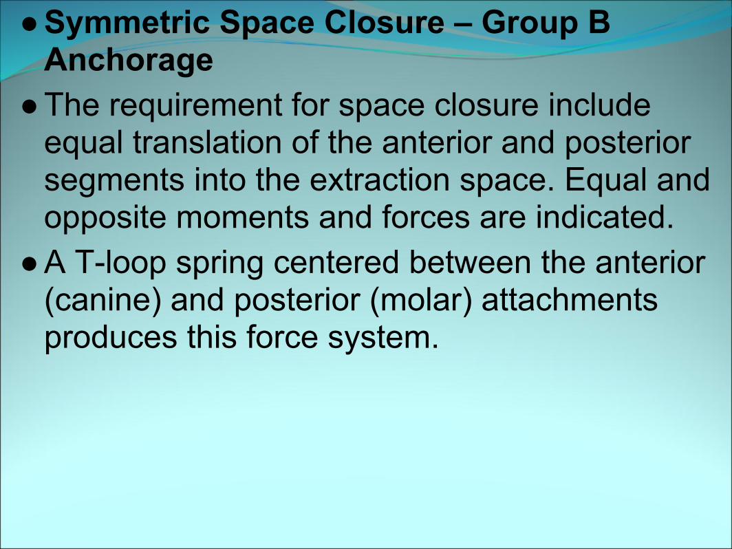
● Symmetric Space Closure – Group B Anchorage
● The requirement for space closure include equal translation of the anterior and posterior segments into the extraction space. Equal and opposite moments and forces are indicated.
● A T-loop spring centered between the anterior (canine) and posterior (molar) attachments produces this force system.
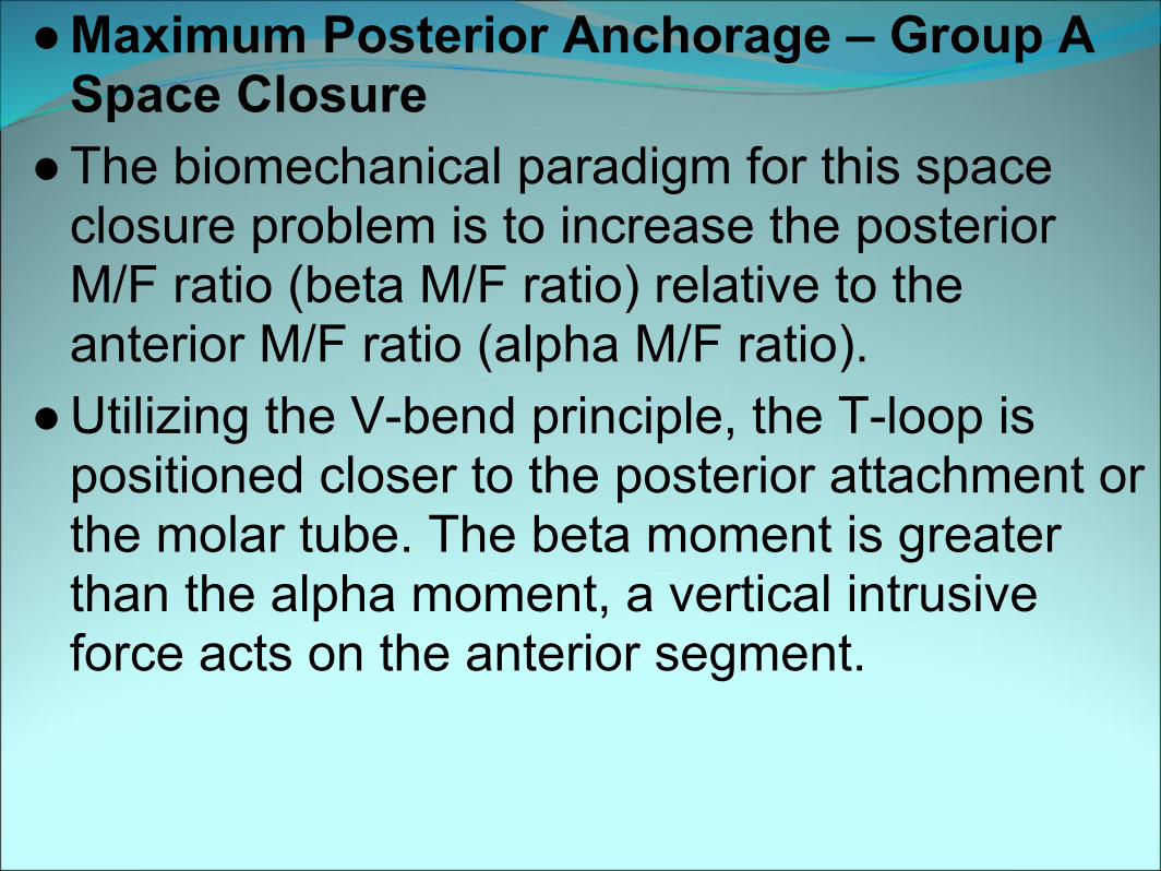
● Maximum Posterior Anchorage – Group A Space Closure
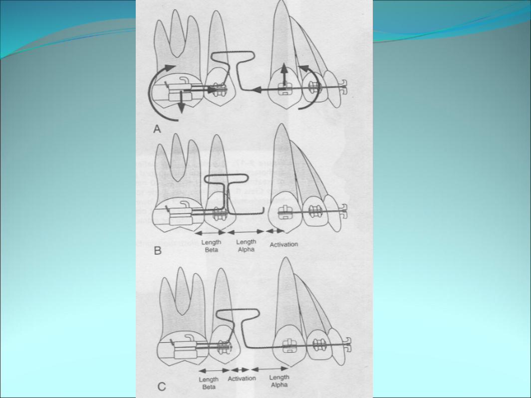
● The biomechanical paradigm for this space closure problem is to increase the posterior M/F ratio (beta M/F ratio) relative to the anterior M/F ratio (alpha M/F ratio).
● Utilizing the V-bend principle, the T-loop is positioned closer to the posterior attachment or the molar tube. The beta moment is greater than the alpha moment, a vertical intrusive force acts on the anterior segment.
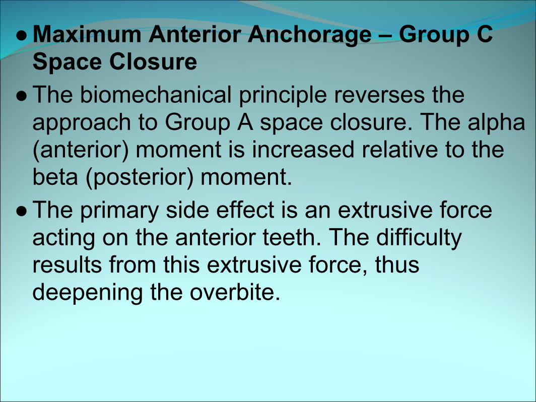
● Maximum Anterior Anchorage – Group C Space Closure
● The biomechanical principle reverses the approach to Group A space closure. The alpha (anterior) moment is increased relative to the beta (posterior) moment.
● The primary side effect is an extrusive force acting on the anterior teeth. The difficulty results from this extrusive force, thus deepening the overbite.
In Group C space closure with a segmented T-loop, the spring is positioned closer to the anterior segment. It is important that the anterior wire segment achieve full bracket engagement; otherwise, the play within the brackets reduces the effectiveness of the moment differential.
Implants as a source of anchorage
● In contemporary orthodontics Implants is the best source of anchorage, which doesn’t rely on patient compliance.
● The pioneering studies on oral implants was done by LINKOW who is rightfully called the Father of Oral Implantology
● Implants are defined as alloplastic devices which are surgically inserted into or onto the jaw bone-Boucher.
● Implants can be used for Space Closure. They are used in the retromolar region to move teeth distally or anteriorly for mesial movement
● Skeletal Anchorage System● (For open bite correction)
● Sugawara; Umemori et al (AJO 1999;115)● They developed skeletal anchorage system using
Titanium plates as a source of anchorage for intruding the molars.
● The implants used are ‘L’ shaped Titanium implants.
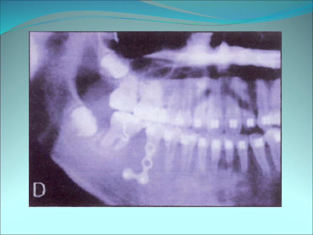
● Surgical Procedure● Done under LA.
● A mucoperiosteal flap is raised in the apical region of the 1st or 2nd molar and the cortical bone is exposed.
● The ‘L’ shaped miniplate is adjusted to fit the contour of the cortical bone and fixed to the bone by using screws, with long arm exposed to the oral cavity.
● After wound healing occurs and elastic force was applied from molar to the miniplate for intrusion .
● Lingual crown torque was applied in the lingual arch to prevent the buccal flaring as the molar intrudes and after the treatment the miniplates are removed.
● Skeletal Anchorage System● (For deep bite correction)
● Creekmore;Eklund et al, the possibility of skeletal anchorage (JCO 1983;17)
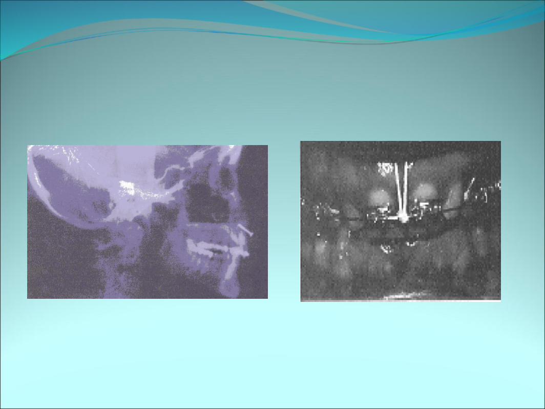
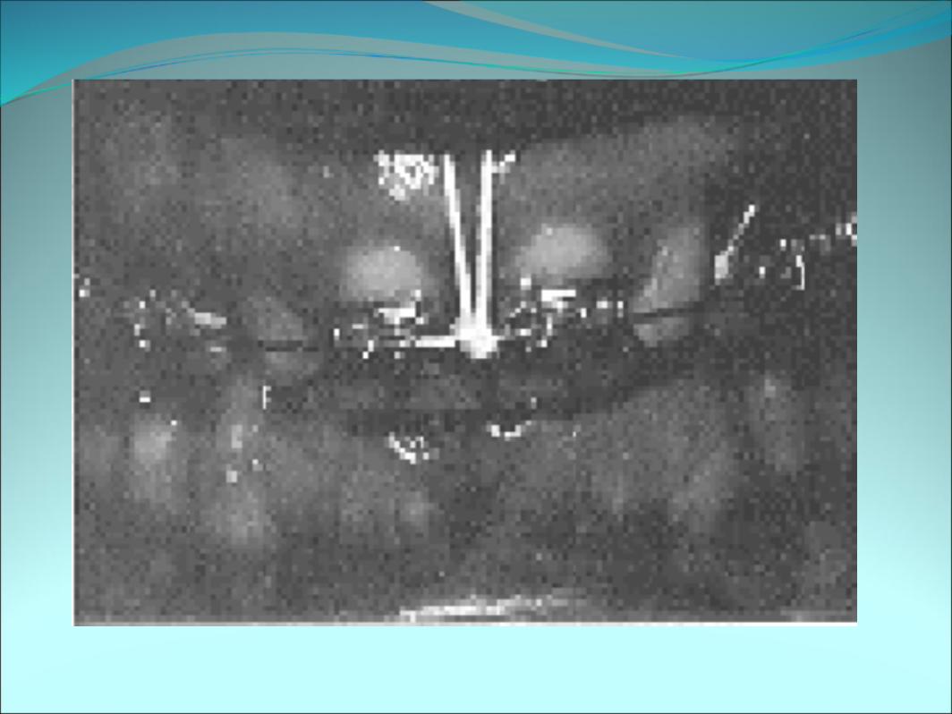
● They inserted a surgical vitallium bone screw just below anterior nasal spine.
● Ten days after the screw was placed,a light elastic thread was tied from the head of the screw to the archwire
● The elastic thread was renewed throughout treatment,so that a continous force was maintained 24 hrs a day.
● After 1 year they found that the maxillary CI were elevated 6mms and torqued lingually about 25 degrees.
● MiniImplant:-● Ryuzo kanomi; Miniimplant for orthodontic
anchorage ;(JCO 1997;31)
● The author used an implant made of miniscrews to fix the bone plates.
● Minimplant-1.2mm in diameter● 6mm in length
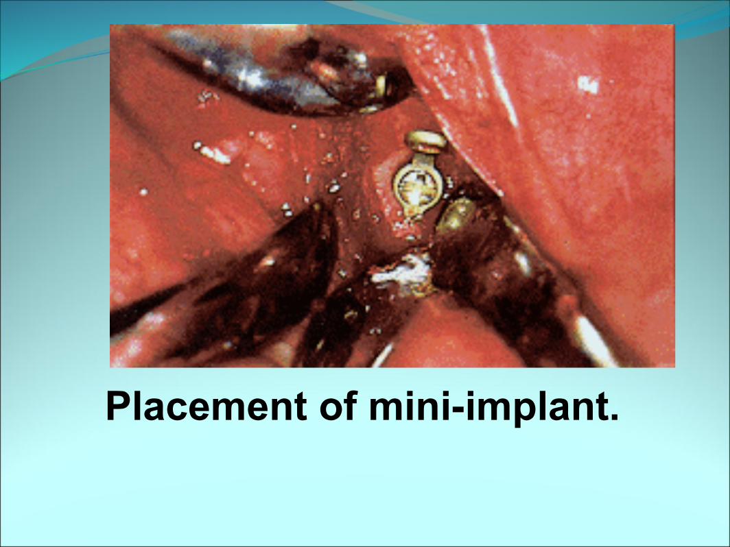
Placement of mini-implant.
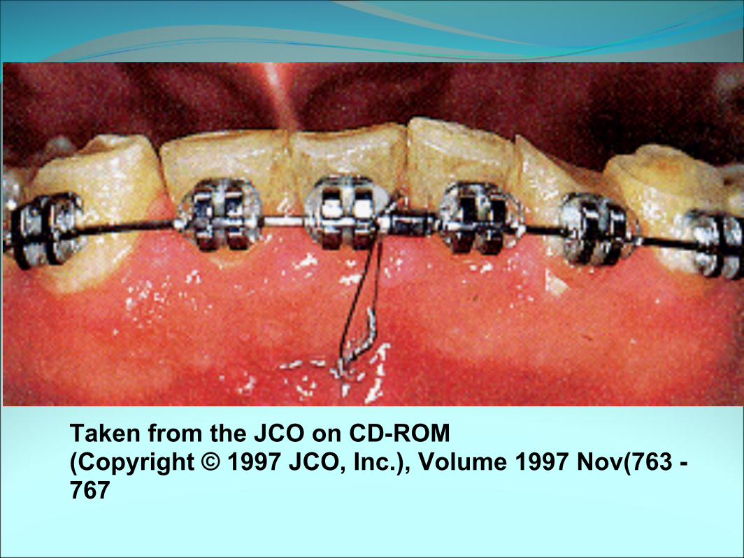
Taken from the JCO on CD-ROM (Copyright © 1997 JCO, Inc.), Volume 1997 Nov(763 - 767
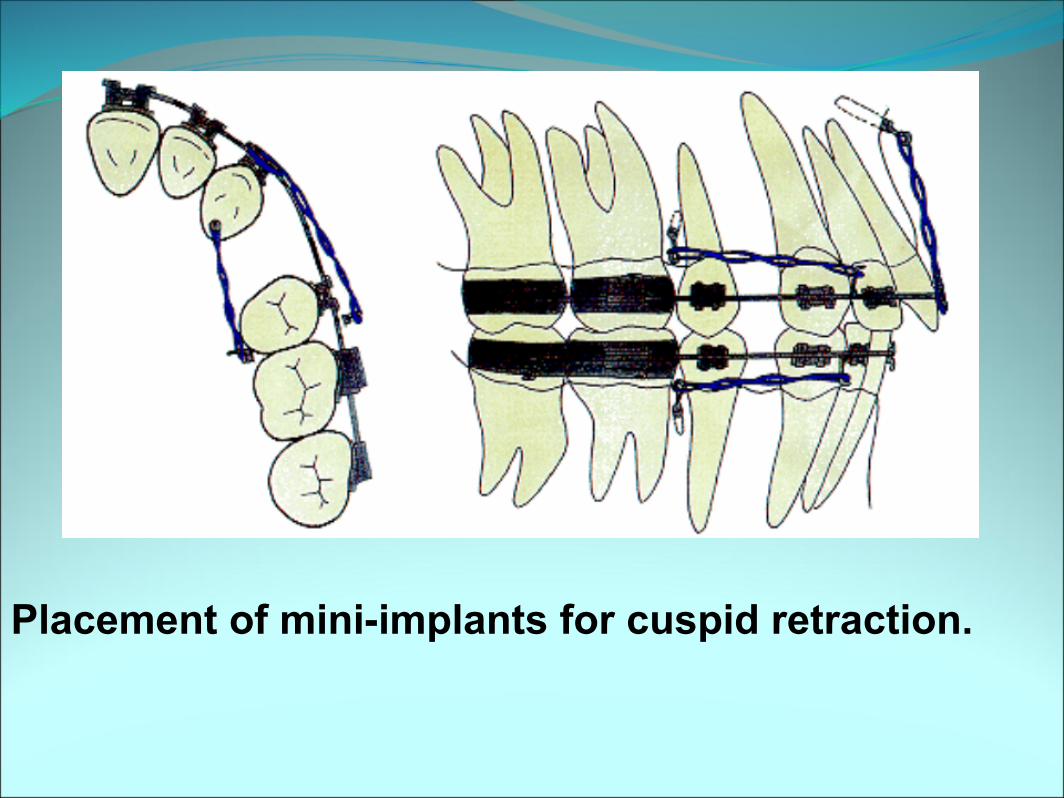
Placement of mini-implants for cuspid retraction.
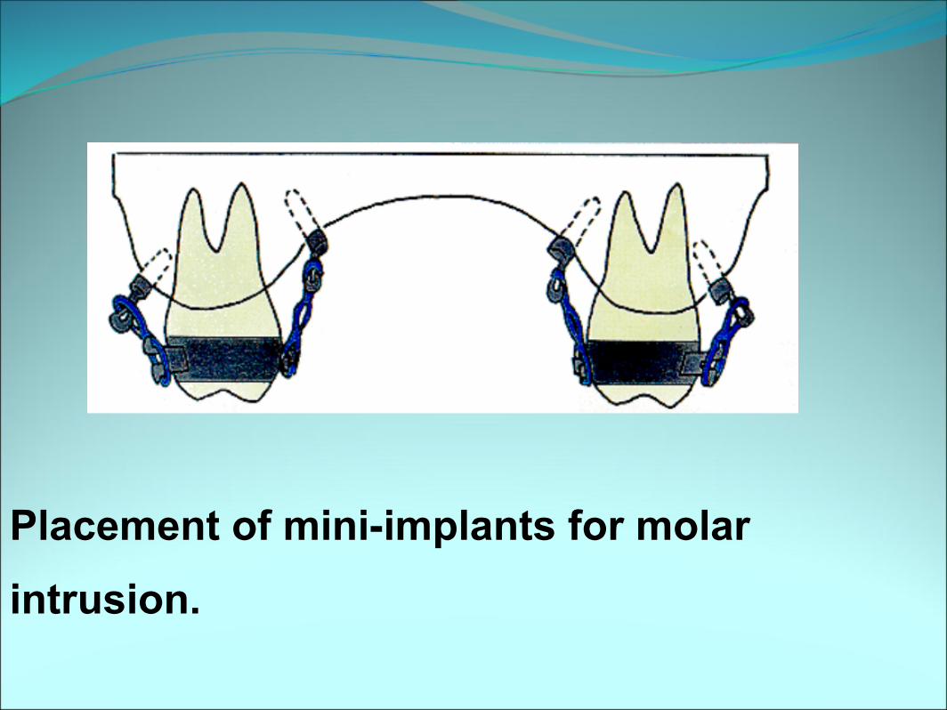
Placement of mini-implants for molar
intrusion.
Conclusion● It is very important to plan anchorage right
before hand so as to have a smooth progression on to a predetermined optimal end result.
● Kind action always invoke kind reactions, so always use kind action forces to have kind reactions forces on the anchorage.
References1. Graber T.M: Orthodontics: Principles & Practice. WB Saunders,19882. Profitt WR: Contemporary Orthodontics, Sr Louis, CV Mosby,19863. Robert E Moyers: Handbook of Orthodontics,Year book medical publishers,inc,19884. Thomas M Graber, Robert L Vanarsdall: Orthodontics current principles& techniques,Mosby year book inc,19945. Evaluation of the vertical holding appliance in treatment of high-angle patients Marcs DeBerardinis, Tony Stretesky, Pramod Sinha, and Ram S. Nanda, AJO 2000, volume 117