
Analyzing the Impact of Supporting Out-of-order Communication on In-order Performance with iWARP P....
29
Analyzing the Impact of Supporting Out-of-order Communication on In-order Performance with iWARP P. Balaji, W. Feng, S. Bhagvat, D. K. Panda, R. Thakur and W. Gropp Mathematics and Computer Science, Argonne National Laboratory Department of Computer Science, Virginia Tech Scalable Systems Group, Dell Inc. Computer Science and Engineering, Ohio State University Computer Science, University of Illinois at Urbana Champagne
-
Upload
benedict-short -
Category
Documents
-
view
213 -
download
0
Transcript of Analyzing the Impact of Supporting Out-of-order Communication on In-order Performance with iWARP P....

Analyzing the Impact of Supporting Out-of-order
Communication onIn-order Performance with
iWARP
P. Balaji, W. Feng, S. Bhagvat, D. K. Panda, R. Thakur and W. Gropp
Mathematics and Computer Science, Argonne National Laboratory
Department of Computer Science, Virginia Tech
Scalable Systems Group, Dell Inc.
Computer Science and Engineering, Ohio State University
Computer Science, University of Illinois at Urbana Champagne

Motivation
• High-end computing systems growing rapidly in
scale– 128K processor system at LLNL (HPC CPU growth of 50%)
– 1M processor systems as soon as next year
• Network subsystem has to scale accordingly
– Fault-tolerance and hot-spot avoidance important
• Possible Solution: Multi-pathing
– Supported by many networks• InfiniBand uses subnet management to discover paths
• 10-Gigabit Ethernet uses VLAN based multi-pathing
– Disadvantage: Out-of-order Communication!

Out-of-order Communication
• Different packets taking different paths mean that later injected packets might arrive earlier
– Physical networks only deal with sending packets out-of-order
– Protocols on top of networks (either in hardware or software) have to deal with reordering packets
• Networks such as IB handle this by dropping out-of-order packets
– FECN, BECN and throttling on congestion
– Network buffering (with FECN/BECN) helps, but not perfect
1234 1
2
34

Overview of iWARP over Ethernet
• Relatively new initiative by
IETF and RDMAC
• Backward compatibility with
TCP/IP/Ethernet
– Sender stuffs iWARP
packets within TCP/IP
packets
– When sent, one TCP packet
contains one iWARP packet
– What about on receive?
Application
Sockets SDP, MPI etc.
Software TCP/IP
10-Gigabit Ethernet
RDMAP Verbs
RDDP
MPA
Offloaded TCP/IP

Ethernet Packet SegmentationPacketHeader
iWARPHeaderData Payload
PacketHeader
iWARPHeader
Data Payload
PacketHeader
iWARPHeader
Data Payload
PacketHeader
iWARPHeader
Partial Payload
PacketHeader
Partial Payload
PacketHeader
iWARPHeader
Data Payload
PacketHeader
iWARPHeader
Data Payload
Delayed Packet Out-Of-Order Packets
(Cannot identify iWARP header)
Intermediate Switch Segmentation
• Intermediate switch segmentation• Packets split or coalesced
• Current iWARP implementations do not handle out-of-order packets• Follow approaches used by IB

Problem Statement
• How do we design a feature-complete iWARP
stack?
– Provide support for out-of-order arriving packets
– Maintaining performance of in-order communication
• What are the tradeoffs in designing iWARP?
– Host-based iWARP
– Host-offloaded iWARP
– Host-assisted iWARP

Presentation Layout
• Introduction and Motivation
• Details of the iWARP Standard
• Design Choices for iWARP
• Experimental Evaluation
• Concluding Remarks and Future Work

Dealing with Out-of-order packets in iWARP• iWARP specifies intelligent approaches to deal with
out-of-order packets
• Out-of-order data placement and In-order data delivery– If packets arrive out-of-order, they are directly placed
in the appropriate location in memory
– Application notified about the arrival of the message only when:• All packets of the message have arrived
• All previous messages have arrived
• It is necessary that iWARP recognize all packets !

MPA Protocol Frame
DDPHeader
Payload (IF ANY)
DDPHeader
Payload (IF ANY)
Pad CRC
MarkerSegmentLength
• Deterministic approach to identify packet header– Can distinguish in-order packets from out-of-order
packets

Presentation Layout
• Introduction and Motivation
• Details of the iWARP Standard
• Design Choices for iWARP
• Experimental Evaluation
• Concluding Remarks and Future Work
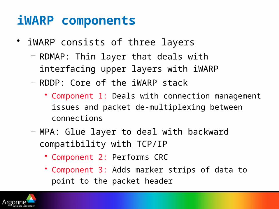
iWARP components
• iWARP consists of three layers– RDMAP: Thin layer that deals with interfacing upper
layers with iWARP
– RDDP: Core of the iWARP stack• Component 1: Deals with connection management
issues and packet de-multiplexing between connections
– MPA: Glue layer to deal with backward compatibility with TCP/IP• Component 2: Performs CRC
• Component 3: Adds marker strips of data to point to the packet header
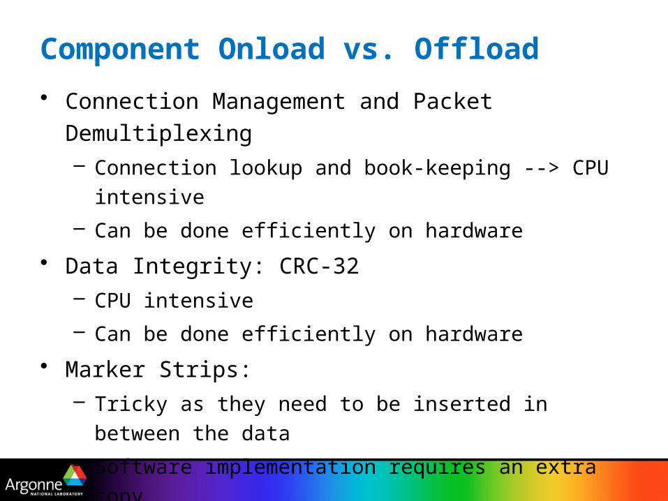
Component Onload vs. Offload
• Connection Management and Packet Demultiplexing– Connection lookup and book-keeping --> CPU
intensive
– Can be done efficiently on hardware
• Data Integrity: CRC-32– CPU intensive
– Can be done efficiently on hardware
• Marker Strips:– Tricky as they need to be inserted in between the
data
– Software implementation requires an extra copy
– Hardware implementation might require multiple DMAs

Task distribution for different iWARP designs
RDMAP RDDP
CRC Markers
TCP/IP
RDMAP Markers
TCP/IP
RDDP CRC
Markers TCP/IP
RDMAP
RDDP CRC
HOST
NIC
Host-based Host-offloaded Host-assisted
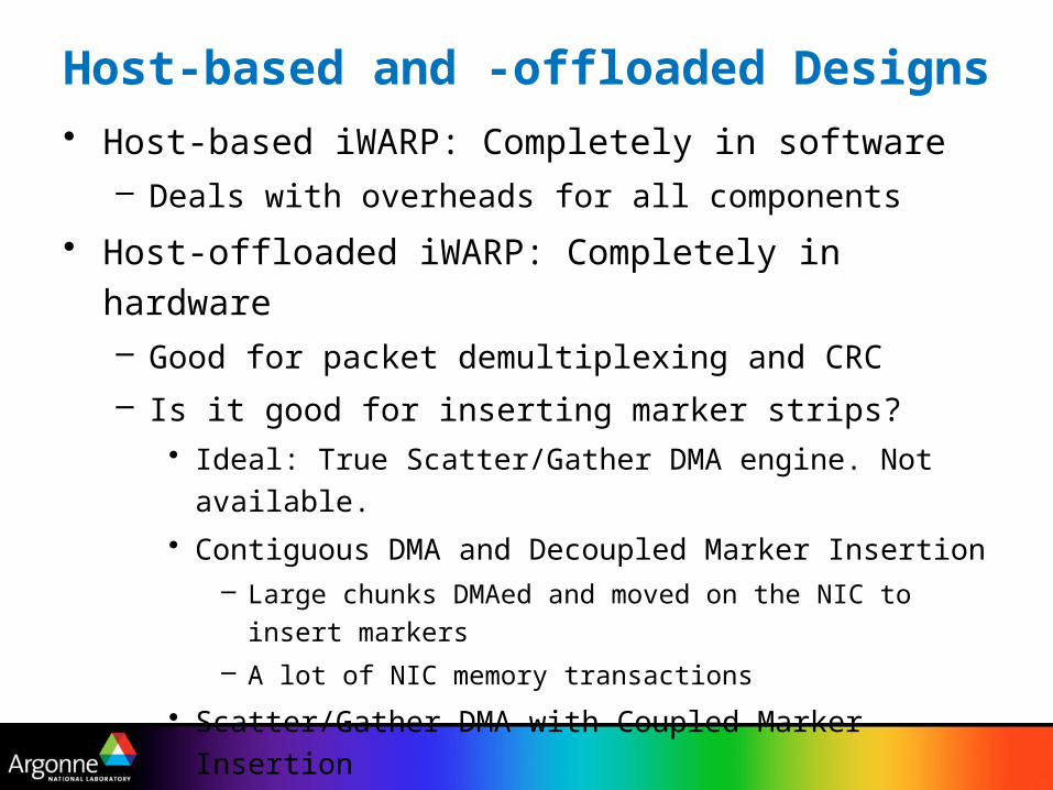
Host-based and -offloaded Designs• Host-based iWARP: Completely in software
– Deals with overheads for all components
• Host-offloaded iWARP: Completely in hardware– Good for packet demultiplexing and CRC
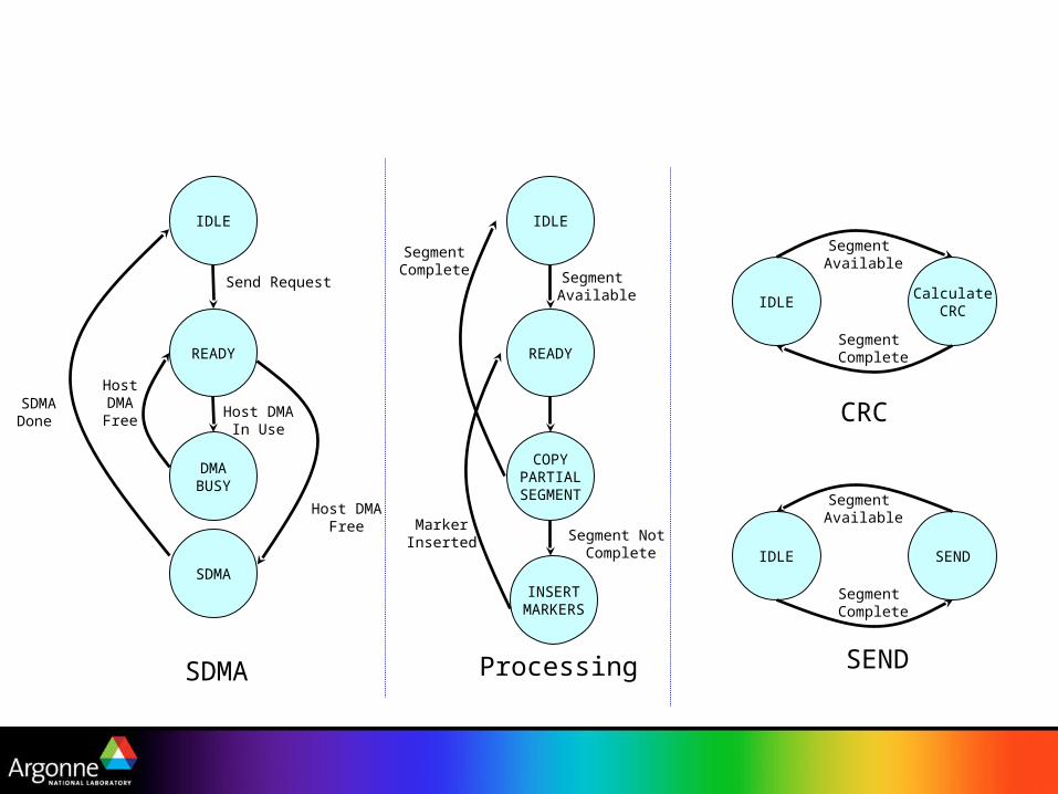
– Is it good for inserting marker strips?• Ideal: True Scatter/Gather DMA engine. Not available.
• Contiguous DMA and Decoupled Marker Insertion– Large chunks DMAed and moved on the NIC to insert
markers
– A lot of NIC memory transactions
• Scatter/Gather DMA with Coupled Marker Insertion– Small chunks DMAed and non-contiguously
– A lot of DMA operations

Hybrid Host-assisted Implementation• Performs tasks such as:
– packet demultiplexing and CRC in hardware
– marker insertion in software (requires an extra-copy)
• Fully utilizes both the host and the NIC
• Summary:– Host-based design suffers from software overheads
for all tasks
– Host-offloaded design suffers from the overhead of multiple DMA operations
– Host-based design suffers from the extra memory copy to add the markers but benefits from less DMAs

Presentation Layout
• Introduction and Motivation
• Details of the iWARP Standard
• Design Choices for iWARP
• Experimental Evaluation
• Concluding Remarks

Experimental Test bed
• 4-node cluster– 2 Intel Xeon 3.0GHz processors with 533MHz FSB,
2GB 266-MHz DDR SDRAM and 133 MHx PCI-X slots
– Chelsio T110 10GE TCP Offload Engines
– 12-port Fujitsu XG800 switch
– Red Hat Operating system (2.4.22smp)

iWARP Microbenchmarks
0
10
20
30
40
50
60
1 2 4 8 16 32 64 128 256 512 1K 2K
Message Size (Bytes)
Late
ncy
(u
s)
Host-offloaded iWARP
Host-based iWARP
Host-assisted iWARP
0
1000
2000
3000
4000
5000
6000
7000
Message Size (bytes)
Bandw
idth
(M
bps)
0
10
20
30
40
50
60
70
80
90
100
CPU
(%)
Host-offloaded iWARP CPU
Host-based iWARP CPU
Host-assisted iWARP CPU
Host-offloaded iWARP
Host-based iWARP
Host-assisted iWARP
iWARP Latency iWARP Bandwidth
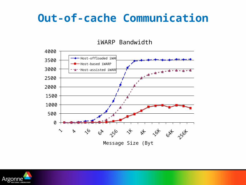
Out-of-cache Communication
0
500
1000
1500
2000
2500
3000
3500
4000
1 4 16 64 256 1K 4K 16
K64
K25
6K
Message Size (Bytes)
Ba
nd
wid
th (
Mb
ps)
Host-offloaded iWARP
Host-based iWARP
Host-assisted iWARP
iWARP Bandwidth
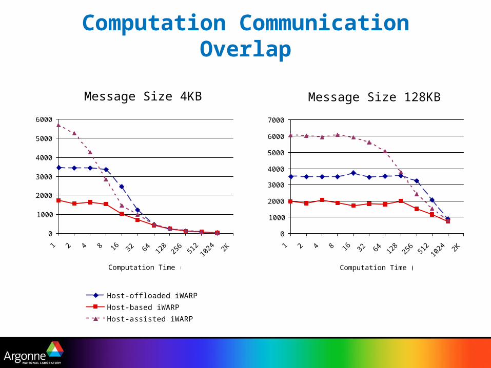
Computation Communication Overlap
0
1000
2000
3000
4000
5000
6000
1 2 4 8 16 32 64 128
256
512
1024 2K
Computation Time (us)
Ban
dw
idth
(M
bp
s)
Host-offloaded iWARP
Host-based iWARP
Host-assisted iWARP
Message Size 4KB Message Size 128KB
0
1000
2000
3000
4000
5000
6000
7000
1 2 4 8 16 32 64 128
256
512
1024 2K
Computation Time (us)
Ban
dw
idth
(M
bp
s)

Iso-surface Visual rendering application
0
50
100
150
200
250
300
350
400
450
1024x1024 2048x2048 4096x4096 8192x8192
Dataset Dimensions
Exe
cuti
on T
ime (
secs
)
Host-offloaded iWARP
Host-based iWARP
Host-assisted iWARP
Data Distribution Size : 8KB
0
100
200
300
400
500
600
1024x1024 2048x2048 4096x4096 8192x8192
Dataset Dimensions
Exe
cuti
on T
ime (
secs
)
Data Distribution Size : 1MB

Presentation Layout
• Introduction and Motivation
• Details of the iWARP Standard
• Design Choices for iWARP
• Experimental Evaluation
• Concluding Remarks

Concluding Remarks• With growing scales of high-end computing
systems, network infrastructure has to scale as well– Issues such as fault tolerance and hot-spot avoidance
play an important role
• While multi-path communication can help with these problems, it introduces Out-of-order communication
• We presented three designs of iWARP that deal with out-of-order communication– Each design has its pros and cons
– No single design could achieve the best performance in all cases

Thank You
Email Contacts:
P. Balaji: [email protected]
W. Feng: [email protected]
S. Bhagvat: [email protected]
D. K. Panda: [email protected]
R. Thakur: [email protected]
W. Gropp: [email protected]

Backup Slides

IDLE
READY
DMABUSY
SDMA
Send Request
Host DMAFree
Host DMABusy
Integrated
SegmentComplete
Host DMAFree
READY
DMABUSY
SDMA
Host DMAFree
Host DMABusy
Host DMAFree
MarkerInserted
SegmentNot Complete
IDLE
READY
DMABUSY
SDMA
Host DMAFree
Send Request
SDMADone
Host DMAFree
Host DMAIn Use
SDMA
IDLE
READY
COPYPARTIAL
SEGMENT
INSERTMARKERS
Segment Available
Processing
Segment Not Complete
MarkerInserted
SegmentComplete
IDLECalculate
CRC
Segment Available
Segment Complete
IDLE SEND
Segment Available
Segment Complete
CRC
SEND

iWARP Out-of-Cache Communication Bandwidth
0
1
2
3
4
5
6
1 16 256 4K 64K 256K
Message Size (Bytes)
Rati
o o
f C
ach
e t
o N
etw
ork
Tra
ffic
Host-offloaded iWARP
Host-based iWARP
Host-assisted iWARP
Cache Traffic (Transmit Side) Cache Traffic (Receive Side)
0
1
2
3
4
5
6
1 16 256 4K 64K 256K
Message Size (Bytes)R
ati
o o
f C
ach
e t
o N
etw
ork
Tra
ffic

Impact of marker separation on iWARP performance
0
5
10
15
20
25
30
35
1 2 4 8 16 32 64 128 256 512 1K 2K
Message Size (Bytes)
Late
ncy
(u
s)
iWARP (original)
iWARP (1KB marker separation)
iWARP (2KB marker separation)
iWARP (no markers)
Host-offloaded iWARP Latency NIC-offloaded iWARP Bandwidth
0
1000
2000
3000
4000
5000
6000
7000
8000
1 4 16 64 256 1K 4K 16
K64
K25
6K
Message Size (Bytes)B
andw
idth
(M
bps)


![ETHERNET XXX IWARP PERFORMANCE STUDY - start [Michael Fenn's Website]](https://static.fdocuments.net/doc/165x107/61fb5ba62e268c58cd5d39af/ethernet-xxx-iwarp-performance-study-start-michael-fenns-website.jpg)