ANALYTICAL APPROACH TO COLLAPSE MECHANISMS … · ANALYTICAL APPROACH TO COLLAPSE MECHANISMS OF...
22
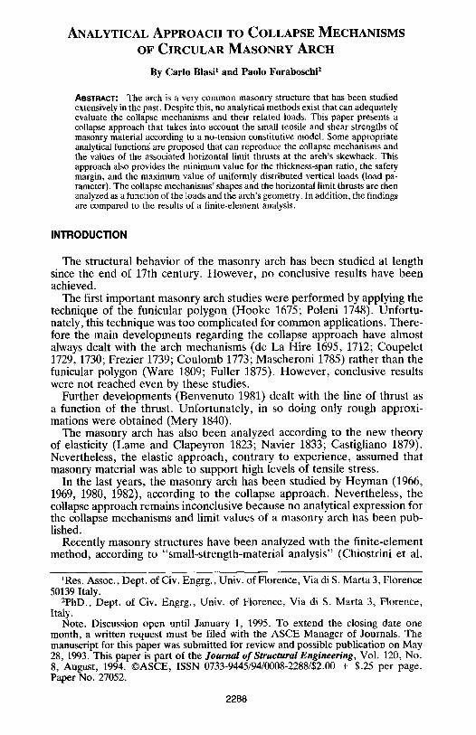
ANALYTICAL APPROACH TO COLLAPSE MECHANISMS OF CIRCULAR MASONRY ARCH By Carlo Blasi t and Paolo Foraboschi 2 ABSTRACT; The arch is a very common masonry structure that has been studied extensivelyin the past. Despite this, no analyticalmethods exist that can adequately evaluate the collapse mechanisms and their related loads. This paper presents a collapse approach that takes into account the small tensile and shear strengths of masonry material according to a no-tension constitutive model. Some appropriate analytical functionsare proposed that can reproduce the collapse mechanisms and the values of the associated horizontal limit thrusts at the arch's skewback. This approach also provides the minimumvalue for the thickness-span ratio, the safety margin, and the maximum value of uniformly distributed vertical loads (load pa- rameter). The collapsemechanisms'shapes and the horizontal limit thrusts are then analyzedas a functionof the loads and the arch's geometry. In addition, the findings are compared to the results of a finite-element analysis. INTRODUCTION The structural behavior of the masonry arch has been studied at length since the end of 17th century. However, no conclusive results have been achieved. The first important masonry arch studies were performed by applying the technique of the funicular polygon (Hooke 1675; Poleni 1748). Unfortu- nately, this technique was too complicated for common applications. There- fore the main developments regarding the collapse approach have almost always dealt with the arch mechanisms (de La Hire 1695, 1712; Coupelet 1729, 1730; Frezier 1739; Coulomb 1773; Mascheroni 1785) rather than the funicular polygon (Ware 1809; Fuller 1875). However, conclusive results were not reached even by these studies. Further developments (Benvenuto 1981) dealt with the line of thrust as a function of the thrust. Unfortunately, in so doing only rough approxi- mations were obtained (Mery 1840). The masonry arch has also been analyzed according to the new theory of elasticity (Lame and Clapeyron 1823; Navier 1833; Castigliano 1879). Nevertheless, the elastic approach, contrary to experience, assumed that masonry material was able to support high levels of tensile stress. In the last years, the masonry arch has been studied by Heyman (1966, 1969, 1980, 1982), according to the collapse approach. Nevertheless, the collapse approach remains inconclusive because no analytical expression for the collapse mechanisms and limit values of a masonry arch has been pub- lished. Recently masonry structures have been analyzed with the finite-element method, according to "small-strength-material analysis" (Chiostrini et al. IRes. Assoc., Dept. of Civ. Engrg., Univ. of Florence, Via di S. Marta 3, Florence 50139 Italy. 2PhD., Dept. of Civ. Engrg., Univ. of Florence, Via di S. Marta 3, Florence. Italy. Note. Discussion open until January 1, 1995. To extend the closing date one month, a written request must be filed with the ASCE Manager of Journals. The manuscript for this paper was submitted for review and possible publication on May 28, 1993. This paper is part of the Journal of Structural Engineering, Vol. 120, No. 8, August, 1994. ISSN 0733-9445/94/0008-2288/$2.00 + $.25 per page. Paper No. 27052. 2288
Transcript of ANALYTICAL APPROACH TO COLLAPSE MECHANISMS … · ANALYTICAL APPROACH TO COLLAPSE MECHANISMS OF...
A N A L Y T I C A L A P P R O A C H TO C O L L A P S E M E C H A N I S M S
OF C I R C U L A R M A S O N R Y A R C H
By Carlo Blasi t and Paolo Foraboschi 2
ABSTRACT; The arch is a very common masonry structure that has been studied extensively in the past. Despite this, no analytical methods exist that can adequately evaluate the collapse mechanisms and their related loads. This paper presents a collapse approach that takes into account the small tensile and shear strengths of masonry material according to a no-tension constitutive model. Some appropriate analytical functions are proposed that can reproduce the collapse mechanisms and the values of the associated horizontal limit thrusts at the arch's skewback. This approach also provides the minimum value for the thickness-span ratio, the safety margin, and the maximum value of uniformly distributed vertical loads (load pa- rameter). The collapse mechanisms' shapes and the horizontal limit thrusts are then analyzed as a function of the loads and the arch's geometry. In addition, the findings are compared to the results of a finite-element analysis.
INTRODUCTION
The structural behavior of the masonry arch has been studied at length since the end of 17th century. However , no conclusive results have been achieved.
The first important masonry arch studies were performed by applying the technique of the funicular polygon (Hooke 1675; Poleni 1748). Unfortu- nately, this technique was too complicated for common applications. There- fore the main developments regarding the collapse approach have almost always dealt with the arch mechanisms (de La Hire 1695, 1712; Coupelet 1729, 1730; Frezier 1739; Coulomb 1773; Mascheroni 1785) rather than the funicular polygon (Ware 1809; Fuller 1875). However, conclusive results were not reached even by these studies.
Further developments (Benvenuto 1981) dealt with the line of thrust as a function of the thrust. Unfortunately, in so doing only rough approxi- mations were obtained (Mery 1840).
The masonry arch has also been analyzed according to the new theory of elasticity (Lame and Clapeyron 1823; Navier 1833; Castigliano 1879). Nevertheless, the elastic approach, contrary to experience, assumed that masonry material was able to support high levels of tensile stress.
In the last years, the masonry arch has been studied by Heyman (1966, 1969, 1980, 1982), according to the collapse approach. Nevertheless, the collapse approach remains inconclusive because no analytical expression for the collapse mechanisms and limit values of a masonry arch has been pub- lished.
Recently masonry structures have been analyzed with the finite-element method, according to "small-strength-material analysis" (Chiostrini et al.
IRes. Assoc., Dept. of Civ. Engrg., Univ. of Florence, Via di S. Marta 3, Florence 50139 Italy.
2PhD., Dept. of Civ. Engrg., Univ. of Florence, Via di S. Marta 3, Florence. Italy.
Note. Discussion open until January 1, 1995. To extend the closing date one month, a written request must be filed with the ASCE Manager of Journals. The manuscript for this paper was submitted for review and possible publication on May 28, 1993. This paper is part of the Journal of Structural Engineering, Vol. 120, No. 8, August, 1994. �9 ISSN 0733-9445/94/0008-2288/$2.00 + $.25 per page. Paper No. 27052.
2288
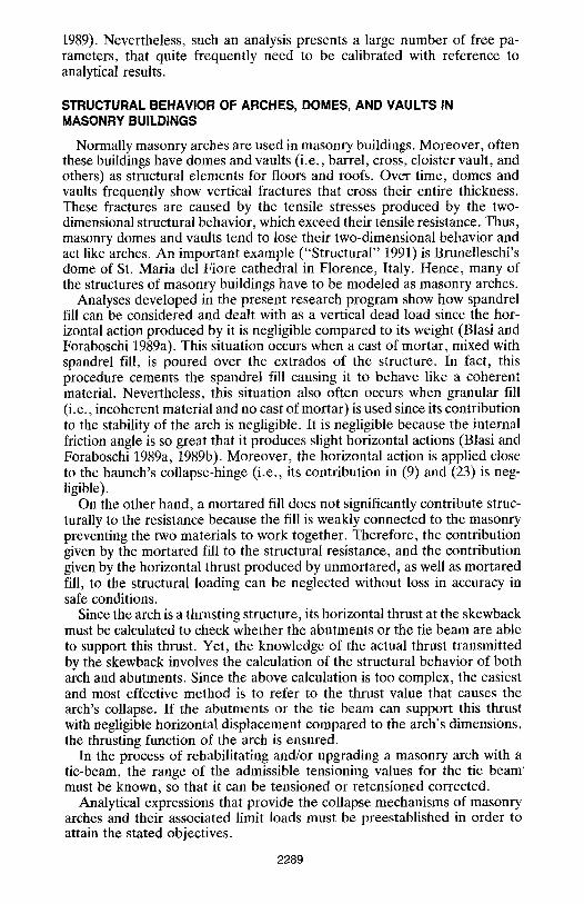
1989). Nevertheless, such an analysis presents a large number of free pa- rameters, that quite frequently need to be calibrated with reference to analytical results.
STRUCTURAL BEHAVIOR OF ARCHES, DOMES, AND VAULTS IN MASONRY BUILDINGS
Normally masonry arches are used in masonry buildings. Moreover, often these buildings have domes and vaults (i.e., barrel, cross, cloister vault, and others) as structural elements for floors and roofs. Over time, domes and vaults frequently show vertical fractures that cross their entire thickness. These fractures are caused by the tensile stresses produced by the two- dimensional structural behavior, which exceed their tensile resistance. Thus, masonry domes and vaults tend to lose their two-dimensional behavior and act like arches. An important example ("Structural" 1991) is Brunelleschi's dome of St. Maria del Fiore cathedral in Florence, Italy. Hence, many of the structures of masonry buildings have to be modeled as masonry arches.
Analyses developed in the present research program show how spandrel fill can be considered and dealt with as a vertical dead load since the hor- izontal action produced by it is negligible compared to its weight (Blasi and Foraboschi 1989a). This situation occurs when a cast of mortar, mixed with spandrel fill, is poured over the extrados of the structure. In fact, this procedure cements the spandrel fill causing it to behave like a coherent material. Nevertheless, this situation also often occurs when granular fill (i.e., incoherent material and no cast of mortar) is used since its contribution to the stability of the arch is negligible. It is negligible because the internal friction angle is so great that it produces slight horizontal actions (Blasi and Foraboschi 1989a, 1989b). Moreover, the horizontal action is applied close to the haunch's collapse-hinge (i.e., its contribution in (9) and (23) is neg- ligible).
On the other hand, a mortared fill does not significantly contribute struc- turally to the resistance because the fill is weakly connected to the masonry preventing the two materials to work together. Therefore, the contribution given by the mortared fill to the structural resistance, and the contribution given by the horizontal thrust produced by unmortared, as well as mortared fill, to the structural loading can be neglected without loss in accuracy in safe conditions.
Since the arch is a thrusting structure, its horizontal thrust at the skewback must be calculated to check whether the abutments or the tie beam are able to support this thrust. Yet, the knowledge of the actual thrust transmitted by the skewback involves the calculation of the structural behavior of both arch and abutments. Since the above calculation is too complex, the easiest and most effective method is to refer to the thrust value that causes the arch's collapse. If the abutments or the tie beam can support this thrust with negligible horizontal displacement compared to the arch's dimensions, the thrusting function of the arch is ensured.
In the process of rehabilitating and/or upgrading a masonry arch with a tie-beam, the range of the admissible tensioning values for the tie beam ' must be known, so that it can be tensioned or retcnsioned corrected.
Analytical expressions that provide the collapse mechanisms of masonry arches and their associated limit loads must be preestablished in order to attain the stated objectives.
2289
NO-TENSION ELASTIC CONSTITUTIVE MODEL FOR MASONRY MATERIAL
Service loads usually produce in masonry structures more tensile, less compressive, and less shear stresses than masonry material can support . Thus, masonry material can be considered as linear-elastic for compressions and as having no-strength for tensions (Villaggio 1981; Blasi and Foraboschi 1989a).
The suggested constitutive model for the collapse analysis is based on the following assumptions:
�9 Tensile stresses are not allowed. Consequently the principal values of the stress tensor [o-] are not positive. This condition is referred to as:
O "max ~ 0 (1)
where o-max = maximum principal stress of [o-]. �9 The strain tensor [e] is given by the sum of an elastic part [ee] and
an inelastic part [so]; the inelastic part is produced by the material cracking
[al = [tel + [~ ] (2)
�9 The cracking strains ~ produce only dilatations of the material at any direction. This s tatement implies that the minimum principal strain ~ " of the cracking strain tensor [~e] is always not negative
~Ti, _> 0 (3)
�9 The normality condition
[~]'[ec] = 0 (4)
is then assumed (thus the principal directions of [o-] and [e~] are the same). Eq. (4) ensures that dilatations for cracking can occur only in the direction for which ~ = 0, and, on the other hand, if o- 4: 0 no dilatation for crack can occur. The normality conditions ensure also that cracking shearing strains can not occur, which would be without physical sense.
�9 The material behavior for compressions is assumed to be linear- elastic
[~1 = [Cl-[o-] + [~J (5)
where the [C] matrix is the elastic-deformability tensor.
The assumed model therefore implies that the stress tensor is a single- valued function of the strain tensor, that is, [o-] = [o-([~])], since
[o-] = [ C ] - ' . ( H - [ ~ ] ) ~ [o-] : [D ] . [% ] (6)
Moreover, it implies that the maximum principal stress ~ x of lee] is non- positive, that is, lee] cannot produce any dilatations.
MECHANICAL HYPOTHESES OF MASONRY ARCH
To deal with the collapse of masonry arches, a one-dimensional behavior was assumed, that is, stresses and strains were assumed to exist in the
2290
transversal sections only. This assumption implies that the constitutive model reduces in the following expression for the total strain e:
if ~ < 0 then ~ = ee (Ta)
if e > 0 then ~ = ~c (7b)
and in the following stress-strain law:
cr = K ' E ' e (8)
w h e r e K - - 0 f o r e > 0 , a n d K = 1 f o r e - < 0 . The one-dimensional behavior hypothesis suggests that the structural state
of the masonry arch can be represented by the line of thrust. According to the adopted no-tension elastic constitutive model, the line of thrust has to be inside the thickness of the transversal section of the arch or at least tangent to the boundary. Therefore, loadings that imply the line of thrust to be outside the arch's thickness cannot be permitted. The tangency con- dition of the line of thrust to the boundary of the arch can be represented with a hinge (not a plastic hinge since inelastic part of [el is caused by cracking).
Provided that the line of thrust is not outside the arch's thickness, the collapse of the arch is reached if a mechanism results once each tangency point with a hinge is substituted. Otherwise the loads have to be further increased to reach the collapse mechanisms.
STRUCTURAL ASPECTS OF MASONRY ARCH
To avoid collapse, an appropriate horizontal thrust should be applied by the abutments at the arch's skewback. The admissible range of values for the horizontal thrust is unique for each arch and applied load. Hereafter, the range is indicated by the lower and upper horizontal thrust limits Hm~n and Hmax, which are the minimum and the maximum values of the thrust that ensure the arch's equilibrium. A thrust value higher than Hm~ produces an "upper collapse mechanism," and a thrust value lower than Hmi, produces a "lower collapse mechanism."
The findings of a special finite-element analysis (see the relevant section) support that fact that the uniform loading is the most representative loading condition. The circular is the most representative shape for masonry arches, as well as domes and vaults, since it is the most common shape, and moreover some arches of noncircular shape are replaced, for analysis purposes, with equivalent circular arches (as proved by the previously mentioned finite- element analysis). Hence, the circular masonry arch with uniform loading, in addition to the self weight, was considered.
Hmi,, AND LOWER COLLAPSE MECHANISM FOR SEMICIRCULAR ARCH
A masonry arch with semicircular intrados and extrados is considered, that is, an arch with constant thickness s. The arch is loaded by its own weight and by a uniformly distributed load q. Referring to Fig. 1, a hinge is set in the intrados in a generic position D (i.e., one hinge for each haunch, thus two hinges) and another hinge is set in the crown section to obtain a collapse mechanism. Then, a roller (that is a hinge permitting the horizontal displacement) is set in the skewback section (i.e., one roller for each skew- back, thus two rollers). The horizontal thrust H transferred between arch
2291
T
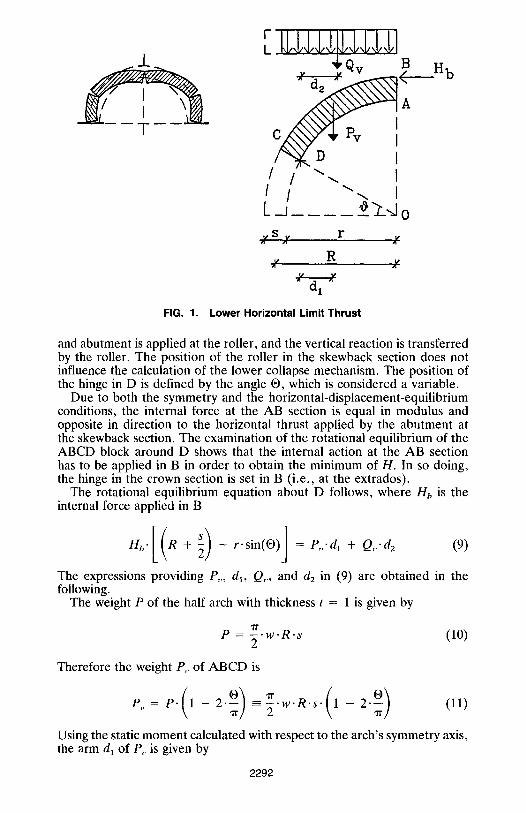
FIG. 1.
F ,
+qv B
/ / ~ I
L o s r
X Z Z
R Z" 2'
Lower Horizontal Limit Thrust
H b
and abutment is applied at the roller, and the vertical reaction is transferred by the roller. The position of the roller in the skewback section does not influence the calculation of the lower collapse mechanism. The position of the hinge in D is defined by the angle O, which is considered a variable.
Due to both the symmetry and the horizontal-displacement-equilibrium conditions, the internal force at the AB section is equal in modulus and opposite in direction to the horizontal thrust applied by the abutment at the skewback section. The examination of the rotational equilibrium of the ABCD block around D shows that the internal action at the AB section has to be applied in B in order to obtain the minimum of H. In so doing, the hinge in the crown section is set in B (i.e., at the extrados).
The rotational equilibrium equation about D follows, where Hh is the internal force applied in B
Hb.[ (R + 2) - r .s in(O)] = P~,.d, + Q,,.d 2 (9)
The expressions providing P,,, d~, Q,,, and d 2 in (9) are obtained in the following.
The weight P of the half arch with thickness t = 1 is given by
"iT e = - ~ . w . R . s (lo)
Therefore the weight P,, of ABCD is
Using the static moment calculated with respect to the arch's symmetry axis, the arm dl of P~, is given by
2292
fl /2 s ' R 2" w" cos(O) = Pv" [r-cos(O) - dl] (12) d~)
Substituting (11) in (12) yields:
s ' R 2 " w ' c o s ( ~ ) ) dO = rr Jo - ~ ' w ' R ' s " 1 - 2. -[r-cos(O) - dl] (13)
Then, dl can be obtained from (13)
2 - R - [ I - sin(O)] dl = r-cos(O) - ~r.(1 - 2-O/7r) (14)
The resultant Qv of the part of q applied on BC is given by
where L indicates span. The arm d2 of Qv is given by the following rela- tionship:
L + s d2 = r-cos(O) 4 cos(O) (16)
Substituting (11), (14), (15), and (16), in (9) and replacing the radius with the span according to R = L/2 and r = (L - s)/2, Hb is given by
Hb = - ~ ' L ' s ' w 1 - 2 �9 "cos(O) -- - sin(O) 1 20/~ J
+ q - - - ~ - cos(O). �9 cos(O) 4
, s ] - - - ~ " sin(O) (17)
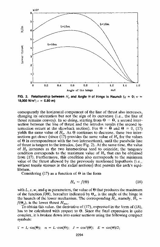
Eq. (17) yields Hb as a function of O [with O in the range of values (0 - ~t/2)l, that is in relation to the position of the hinge D in the haunch. This relation is plotted in Fig. 2 for different spans and prefixed values of s, q, and w. Since only one O value of the range for each curve is correct, the others represent unrealistic collapse mechanisms.
The correct O value is unknown. Therefore, the lower collapse mechanism has to be calculated first, so as to evaluate O. Then, the lower horizontal limit thrust can be calculated from (17).
It can be noted that the line of thrust passes through D. If D were in the crown section (in the intrados), that is, if the value of the angle O of the hinge in the haunch were ~/2 ~ 1,571, the line of thrust would be vertical (since it has to pass through B and D, that are on a vertical line), thus intersecting the arch's intrados. To maintain the equilibrium of ABCD, tensile stresses are necessary in the radial sections where the line of thrust is outside the thickness. Nevertheless, according to the hypotheses, tensile stresses in the radial sections are not permitted. Therefore, the last hinge cannot be in the crown section, and O has to be decreased (i.e., O < 7/2).
As the O value decreases from -rr/2, Hb increases starting from 0, and
2293
4~
3
2
1
x l O 4
. . , , , ,
71 ~ = l g r a
6
0 0.2 0.4 0.6 0.8 1 1.2 1.4 1.6 Angle of the hinge tad
FIG. 2. Relationship between Hb and Angle (9 of Hinge in Haunch (q = 0; w = 18,000 N/m3; s = 0,90 m)
consequently the horizontal component of the line of thrust also increases, changing its orientation but not the sign of its curvature (i.e., the line of thrust remains convex). In so doing, starting from 19 = O, a second inter- section between the line of thrust and the intrados results (the second in- tersection occurs at the skewback section). For O = 0 and (9 = 0, (17) yields the same value of Hb. As 19 continues to decrease, these two inter- sections get closer (since (17) provides the same value of lib for the values of O in correspondence with the two intersections), until the parabolic line of thrust is tangent to the intrados, (see Fig. 2). At the same time, the value of Hb increases as the two intersections tend to coincide; the tangency condition corresponds to the maximum value of Hb that can be obtained from (17). Furthermore, this condition also corresponds to the minimum value of the thrust allowed by the previously mentioned hypothesis (i.e., without tensile stresses in the radial sections) that permits the arch's equi- librium.
Considering (17) as a function of 0 in the form
Hb = y (o ) (18)
with L, s, w, and q as parameters, the value of O that produces the maximum of the function f(O), hereafter indicated by Oa, is the angle of the hinge in the haunch of the lower mechanism. The corresponding Hb, namely, Hb = f(Oa), is the lower thrust Hmin.
To obtain this value, the derivative of (17), expressed in the form of (18), has to be calculated with respect to | Since the final expression is quite complex, it is broken down into easier sections using the following compact symbols:
F = L.sin(| ct = L.cos(O); J = cos2(O); E = sin(|
2294

I~ = s ' s i n ( O ) ; f~ = s-cos(O); 5 = L/2; Q = q/2; Z = 1 - 2.O/7r (19)
The following partial expressions are also obtained:
F = 8 + Q; G = F/2; X = ( L ' Q + s . Q ) . ( L . J / 4 - (3 . s . J /4 )
�9 { ~ / [ 2 - ( F - G + /x/2)z]} - f~/[2(5 + s/2 - G + i~)z]) (20)
The derivative of f with respect to O, indicated by H~(| is expressed by the following final equation:
H~(| = {Z . ( s + w/4 + ~r'L)'{ed('rr - 2 . | - G + tx/2 - 2 - L
/[~,2(1 - 2 " 0 / = ) 2] + 2-F/(rr2"Z2)} + [ - 2 " L - 2"s/=
- w/(2.~r)].{ed2 - ~ /2 + [ - L / ~ r + ( r / w ) / z ]
+ ( - a . E + 3 . 1 2 . E ) . ( L . q / 2 + s . Q ) } / ( F - G + 1~/2)
+ Z . (s + w/4 + ~r .L) . [a /2 - ~ /2 + ( - L / ~ r + r/~r)/Z]} + X (21)
Eq. (21) is plotted in Fig. 3 using prefixed values of the parameters L, s, w, and q. As in Fig. 2, only one point represents a realistic collapse mech- anism.
To obtain the maximum of (18), and hence the lower mechanism, (21) has to be equal to 0
H~(O) = 0 (22)
The solution of (22) yields the value Od of the angle (9 of the hinge in the
x l O 4 6
4
Z 2
o
.~ - l O
- 1 4 ' ~ J , ~ , , 0 0 . 2 0 . 4 0 . 6 0 . 8 1 1 . 2 1 .4 1 ,6
A n g l e o f t h e h i n g e r a d
FIG. 3. Relationship between Derivative of H~ and O (q = 0; w = 18,000 N/mS; s
= 0 . 9 0 m ; L = 1 4 m )
2295
haunch. Then, substituting the 0 d value into (17), the lower thrust is ob- tained.
//max AND UPPER COLLAPSE MECHANISM FOR SEMI-CIRCULAR ARCH
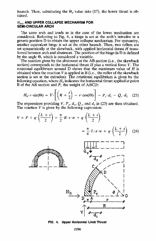
The same arch and loads as in the case of the lower mechanism are considered. Referring to Fig. 4, a hinge is set at the arch's intrados in a generic position D to obtain the upper collapse mechanism. For symmetry, another equivalent hinge is set at the other haunch. Then, two rollers are set symmetrically at the skewback, with applied horizontal thrust H trans- ferred between arch and abutment. The position of the hinge in D is defined by the angle O, which is considered a variable.
The reaction given by the abutment at the AB section (i.e., the skewback section) corresponds to the horizontal thrust H plus a vertical force V. The rotational equilibrium around D shows that the maximum value of H is obtained when the reaction V is applied in B (i.e., the roller of the skewback section is set at the extrados). The rotational equilibrium is given by the following equation, where Hb indicates the horizontal thrust applied at point B of the AB section and Po the weight of ABCD:
The expressions providing V, Pv, dl, Q~, and d2 in (23) are then obtained. The reaction V is given by the following expression:
V = P + q. = - ~ . R . s . w + q .
- "~" " s ' w + q" (24)
qV ~ "-I
I / 1 " - -
Hb Pv >BsA
X X r
FIG. 4. Upper Horizontal Limit Thrust
0 j,,
X
2296
The weight Pv of ABCD is given by
Pv = -~ 'R ' s 'w" = -~ . s .w .O (25)
The static moment with respect to the arch's axis of symmetry is used to determine the a r m d I Of the force Pv, yielding the following expression:
f ~ s .R2 .w.cos(O) = R . s .w .O . [ r . cos (O) + dl] (26) d(~
Eq. (26) yields:
dl = R.sin(O) r.cos(O) = L sin(O) L - S.cos(O) (27) O 2 O 2
The length of the projection of BC on the horizontal plane is given by the following expression:
B---C - L + s.[1 - cos(O)] (28) 2
The resultant Qv of the portion of q applied to BC is given by:
L + s _ Q~ = q . - - ~ ' l 1 - cos(e)] (29)
The arm d2 of the resultant Qv is:
d2 L + - 4 ~ s . [ 1 - cos(O)] + s.cos(O) (30)
Substituting (24), (25), (27), (29), and (30) into (23) and replacing R and r with the span L, Hb is expressed by:
lib = . L . s . w + q 2 ~- .cos(O
L 2 L L - s ] - -~-.s.w.sin(O) + 2 2 s .w.O-cos(O)
�9 sin(O) - 2 . q - ~ - - ~ . [ 1 - cos(O)] + q
Eq. (31) is plotted in Fig. 5 and yields Bib in relation to O, or, in other words, in relation to the unknown position of the hinge D in the haunch. To obtain the upper horizontal limit thrust from (31), the value of O cor- responding to the upper mechanism must be evaluated. Structural consid- erations similar to those developed for the lower thrust show how the value of the upper thrust is the minimum value of Hb with respect to O. Expressing (31) as a function of O yields:
2297

z
xlO 4 9.5
9
8'5~
7�9
7
6.5
j f
J
_ J
L=13m
L=10m
i i i . i i
0.4 0.6 0~8 1 1.2 1.4 1.6
Angle of the hinge rad
FIG. 5. Relationship betweenHband Angle @ of Hinge in Haunch (q = 0; w = 18,000 N/mS;s = 0.90m)
Hb = f(O) (32)
with L, S, w, and q as parameters. The | value that produces the minimum of the function f(O), indicated by 06, is the angle of the hinge in the haunch of the upper mechanism, and the associated H b value is the upper thrust Onaax
Again, to calculate the minimum, the derivative of (32) with respect to 0 has to be evaluated�9 If the compact symbols in (19) are used, the following partial expressions can be obtained:
U = M . L . | Y = M . s ; B = G - ix/2; M = L . s . w ; qb = 4-s (33)
The derivative of Hb = f( | with respect to (9, which is still indicated with H~(O), is expressed by the following final equation:
H~,(O) = {-ot/(Z�9 2) -t- f~/[Z(G - s ' E ) Z l � 9 1 4 9 1 7 4 - q
�9 (1 - 9t/s)2F2/2 + (F - a/2) + f~/2]" (~r" Q/4 + L" Q + s ' Q )
+ U'f~/gp - 2 . M . L , E } + [ Y ' | - Y . f l / + + 2 . q . F2.~2-E/2
- 2 " q - F 2" E + B(~T, m / 4 + L" Q + s" Q) - U . El2 - 3" Y" f~/(~]/B
(34)
Eq. (34) is plotted in Fig. 6. To obtain the maximum of (31), and hence the upper mechanism, (34) has to be set to 0:
/ / ; ( e ) = 0 (35)
The upper thrust is obtained by substituting the (9 value given by (35), that is, (ga. Hence, (34) and (31) are the analytical expressions that provide the upper collapse mechanism and thrust.
2298

x l O 4
- 1 ;
-2
- 3
- 4
-5
- 6
- 7
0 .4 0 .6 0.8 1 1.2 1.4 1.6
Angle of t h e h i n g e r a d
FIG. 6. Relationship between Derivative of Hb and 19 (q = 0; w = 18,000 N/m3; s = 0 . 9 0 m ; L = 14m)
CRUSHING STRENGTH OF MASONRY MATERIAL: INFLUENCES ON THRUSTS AND MECHANISMS
According to the proposed collapse approach, the stress level reached by each collapse mechanism is theoretically infinite in correspondence with the hinges. Thus the limit thrusts as well as the mechanisms are only theoretical. A corrective term is then introduced into the analytical functions in order to give the possibility of taking into account the actual masonry crushing strength. Thus, (8) is replaced with
= kp'E-~ (36)
where k e = 0 for e -> 0; kp = 1 for eo < e < 0; and kp = ~Lim/E'e for e --< eo, and where O'Li m = crushing strength; and eo = yielding strain.
The axial force N, that is, the component of the line of thrust normal to the cross section, was considered. The distance of the line of thrust with respect to both arch's intrados and extrados must be greater than the fol- lowing 13 value to ensure admissible compressive stresses:
N N = - , (with t = 1) (37)
f3 2. t" (~Lim 2 " O'Li m
To obtain the maximum distance (i.e., the maximum value of 13), the max- imum value of N among all the values in correspondence with the hinges has to be set in (37).
In the case of the lower mechanism, the rollers at the skewback are active when the mechanism is completed (i.e., when the rollers at the skewback work the mechanism is already occurred); thus, the stress level reached at the skewback is not influent. The value of N in correspondence with the hinge in the haunch, hereafter indicated by Nh, is greater than the value of
2299
N in correspondence with the hinge in the crown. Hence, Nh is the value to set in (37).
In the case of the upper mechanism, Nh is greater than the value of N in correspondence with the hinge in the skewback section; hence, Nh is still the value to set in (37).
Availing of the tangency condition, the value of Nh can be expressed by
Nh = "L.s . t 'w + q" - -~ .s ' t .w.O
L + s - }z ] - q ' ~ ' [ 1 - cos(O)] + H 2 (38)
where H indicates either Hmi, or Hm .... according to the collapse mechanism that is considered.
Substituting (38) into (37), the distance 13 is found. The following expres- sion can then be written:
N ~ S ' s - / [ { 4 . L . s . t . w + q . ( L - - ~ f s ) S ' - - s - - 13 = S 2 . t . O . L i m
- L ' s ' t ' w ' O - q ' - - - - ~ ' [ 1 - cos(O)l + (2"t'O'Lim) (39) 2
where S' indicates the reduced thickness. When S' replaces s in (17), (21), (31), and (34), the maximum stress level in the arch does not exceed ~Lim-
TO use (39), O and H (i.e., either H m i " o r Hmax) have to be determined beforehand. Thus, (39) is an iterative formula.
Frequently, the above thickness's reduction is so slight that it can either be neglected or the value yielded by (39) without iterating can be used, especially in the case of the lower mechanism.
For example, the 13 value for the arch with L = 14 m, s = 0.90 m, t = 0.50 m, q = 0, w = 18,000 N/m 3, and cri_~m = 3 N/mm 2 in the lower collapse mechanism condition (i.e., O = 0.582, H = H m l n = 66,281 N) at the first iteration is 0.029 m. This value implies that S'/s = 96.7%. Thus, only a slight reduction turns out, even in correspondence with a nonhigh masonry crushing strength (if no mortar joint is close to O = 0.582, the voussoirs' crLi m can be considered).
H,~j. AND/-/max AND LOWER AND UPPER COLLAPSE MECHANISM FOR CIRCULAR MASONRY ARCH
Eqs. (17), (21), (31), and (34) apply only to semicircular masonry arches, that is, to arches where the angle Oa formed by each of the two extreme cross sections to the horizontal is equal to 0 ~ Nevertheless, the methodology was extended so as to include all types of circular arches, that is, arches of 0 -- O~ < 90 ~
To update the theory on the lower mechanism and thrust, O. has to be considered, and the O value yielded by (21) and (22), namely, O~, has to be compared with Oa. If O. -> Oa, O. is correct, and the thrust can be calculated with (17) by using Oa. If instead Oa < Oa, then Oa is not correct. In this case, the angle of the unknown hinge in the haunch is O = O., and the thrust is that given by (17), provided that O. replaces O. (in this case
2300
(21) and (22) are not used). This is supported by the fact that the part of the line of thrust to which the collapse mechanism depends on is that from the crown up to the hinge in the haunch.
When O, -> 30 ~ the thrust can be calculated by using the only equation (17) in correspondence with O = | without excessive loss in accuracy.
To update the theory on the upper mechanism and thrust, (31) and (34) have to be modified, since the part of the line of thrust on which the collapse mechanism depends is that from the skewback up to the hinge in the haunch.
Nevertheless, the upper mechanism is not significant for arches of 30 ~ < Oa, since quite frequently it is preceded by the crushing collapse. There- fore, when tensioning a tie beam in arches of | > 30 ~ the crushing strength limit has to be referred to rather than the upper collapse mechanism.
MINIMUM VALUE FOR THICKNESS-SPAN RATIO
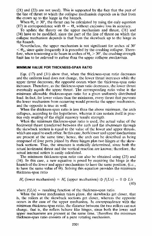
Eqs. (17) and (31) show that, when the thickness-span ratio decreases and the uniform load does not change, the lower thrust increases while the upper thrust decreases; the opposite occurs when the thickness-span ratio increases. Therefore, as the thickness-span ratio decreases, the lower thrust eventually equals the upper thrust. The corresponding ratio value is the minimum allowable thickness-span ratio for a given uniformly distributed load. In fact, for lower values than the minimum, every thrust that prevents the lower mechanism from occurring would provoke the upper mechanism, and the opposite is true as well.
When the thickness-span ratio is less than the above minimum, the arch collapses, according to the hypotheses, whereas it can sustain itself in prac- tice only availing of the slight masonry tensile strength.
When the minimum thickness-span ratio is used, the actual value of the horizontal thrust transferred between the arch and the abutments through the skewback section is equal to the value of the lower and upper thrusts, which are equal to each other. In this case, both lower and upper mechanisms are present at the same time; hence, the arch can be described as being composed of four parts joined by three hinges plus two hinges at the skew- back sections. Thus, the structure is statically determined, since both the actual horizontal thrust and the vertical reaction are known; therefore, the actual internal action is easily calculated.
The minimum thickness-span ratio can also be obtained using (21) and (34). In this case, a new equation is posed by requiring the hinge in the haunch of the lower and upper mechanisms to have the same position, (i.e., to have the same value of | Solving this equation provides the minimum thickness-span ratio
H~(lowermechanism) = Hi (upper mechanism) ~ f ( L / s ) = O ~ L / s (40)
where f(L/s) = resulting function of the thickness-span ratio. When the lower mechanism takes place, the skewbacks get closer, that
is, the rollers at the skewback sections get closer, whereas the opposite occurs in the case of the upper mechanism. In correspondence with the minimum thickness-span ratio, the distance between the two rollers can not change, that is, the rollers behave like hinges, since both the lower and upper mechanisms are present at the same time. Therefore the minimum thickness-span ratio consists of a pure rotating mechanism.
2301
..J
x l0 4 14
lo
6
4
2
i 0.2 0.4
Upper thrust
" " - , %
",, Lower thrust N'NN
"\N
0.6 0.8 1 1.2 1.4 Angle of the hinge rad
1,6
FIG. 7. Hb(O) for Minimum Thickness-Span Ratio (q = 0; w = 18,000 N/m3; s = 0.90 m; L = 17 m)
An example is shown in Fig. 7. A masonry arch with a 17-m span is considered. Following the above procedure, a 0.90-m value for the minimum thickness is obtained. The point where the two curves are tangent provides both the value of the unique horizontal thrust and the position of the hinge in the haunch.
SAFETY MARGIN O F M A S O N R Y A R C H
To assess the safety margin of a masonry arch, the difference between H i . and Hma x must be calculated, together with the actual value of the thrust transferred between the abutment (or tie beam) and the arch at the skewback. Since the actual value of the thrust depends on an arch's and abutments' stiffnesses, it is difficult to evaluate. Nevertheless, the stiffness varies due to creep, cracking, and other factors; hence, the actual value of the horizontal thrust has a limited application. Therefore, only Hmi n and Hma~ should be taken into account, rather than the actual value of the horizontal thrust, when the safety margin of a masonry arch is calculated.
The proposed definition for the safety margin of the masonry arch, here- after indicated by cI), is the following:
0 = /-/max -- Hmin (Hma x + Hmin)/2 (41)
The value of qb in (41), which depends on L, s, w, and q, expresses the maximum possible safety resources of the masonry arch under a given load q.
As an example, a masonry arch with a 0.90-m thickness and loaded only by its own weight is analyzed by varying its span and calculating the safety margin ~ from (41). The values obtained are reported in Table 1.
Table 1 shows that, when the span increases (i.e., the thickness-span ratio decreases), qb decreases. The 17-m span is a limit value, since the corre-
2302
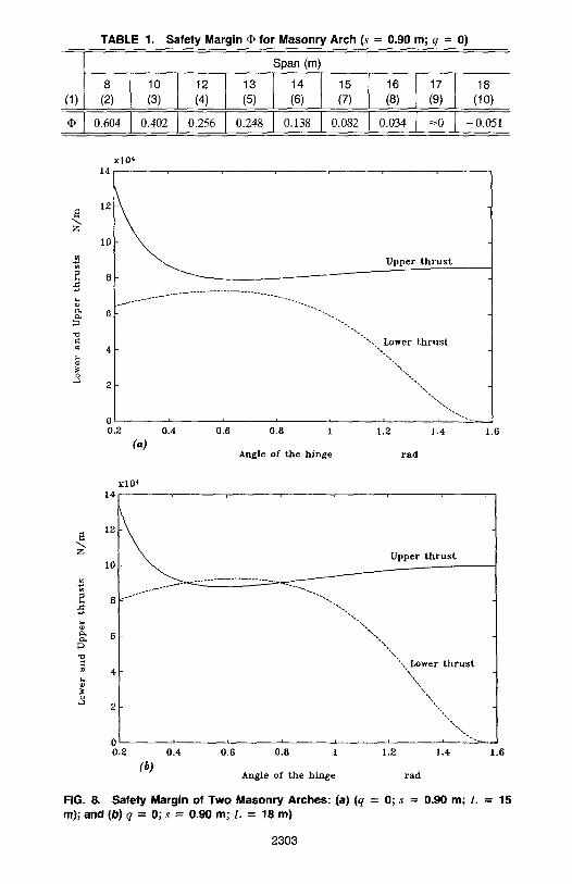
TABLE 1. Safety Margin r for Masonry Arch (s = 0.90 m; q = 0)
(1) 8
(2)
0.604
10
(3)
0.402
12
(4)
0.256
13
(5)
0.248
Span (m)
14 (6)
0.138
15 (7)
0.082
16
(8)
0.034
17 18 (9) (10)
~ 0 - 0.051
x|O 4 14
Z
12
101
Upper t h r u s t
6 " " - 4 " %
4 "-.. Lower t h r u s t
0.2 0.6 1.2 ! .4 , f
0.4 0.8 1 (a)
Angle of the hinge rad
1,6
Z
3
xl0 4 14 , , , ,
lo
" .
Upper t h r u s t
i t i r 0.4 0.6 0.8 1 1.6
6
4
2
0 0.2
(b)
',, Lower t h r u s t
"N,\N
"N-, N
1.2 1.4
Angle of the hinge rad
FIG. 8. Safety Margin of Two Masonry Arches: (a) (q = 0; s = 0 . 9 0 m; L = 15 m ) ; a n d ( b ) q = 0 ;s = 0 . 9 0 m ; L = 1 8 m )
2303
x l O 4 16 , .
14 t / / / / ~ ~ = 2 0 0 0 0 N/m
lo
i
0 0.2 0.4 0.6 0.• 1 1.2 1.4 1.6 (a)
Angle of the hinge rad x l O ~
1 . 8
q=20000 N/rfx
t.6 g 7
1,4
0 .8 ~
0 .6 ' 0 . 4 0 . 6
(b)
q=8000 N/m
q=0
J i i i
0 . 8 1 1 .2 1 .4 ! . 6
A n g l e o f t h e h i n g e t a d
FIG. 9. Relation of Thrust and • in Arch with s = 0.90 m, w = 18,000 N/m s, and L = 15 m: (a) Lower Thrust; and (b) Upper Thrust
sponding ~ is practically zero, whereas for L = 18 m, �9 is negative, that is, the arch cannot sustain itself.
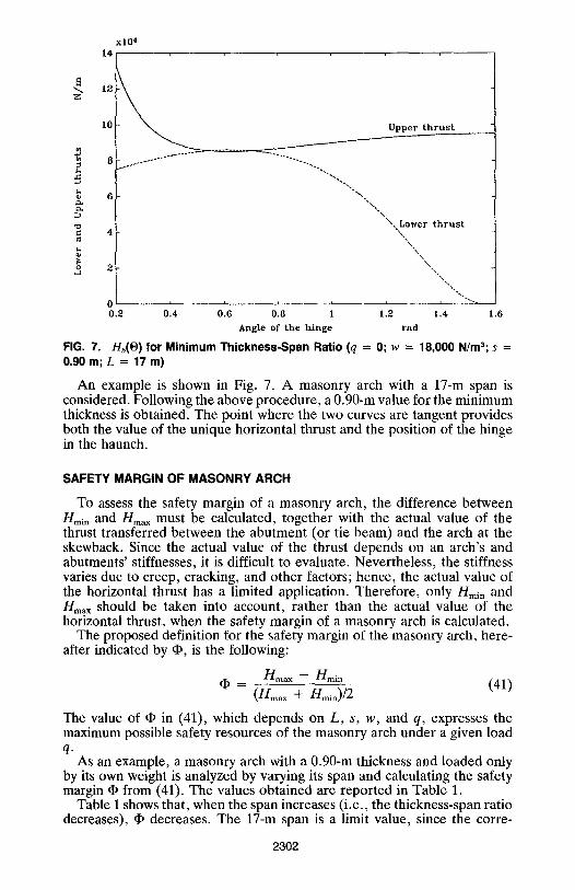
To illustrate the safety margin more accurately, the behavior of the two curves (17) and (31) is reported for two of the arches that have been analyzed in the previous example. The case of the 15-m-span arch is shown in Fig. 8(a), where the safety margin �9 is represented by the minimum distance between (17) and (31). The case of the 18-m-span arch is shown in Fig. 8(b). Since the span limit is about 17 m, the 18-m-span arch cannot support
2304
its own weight. This fact is pointed out by the two intersections between (17) and (31).
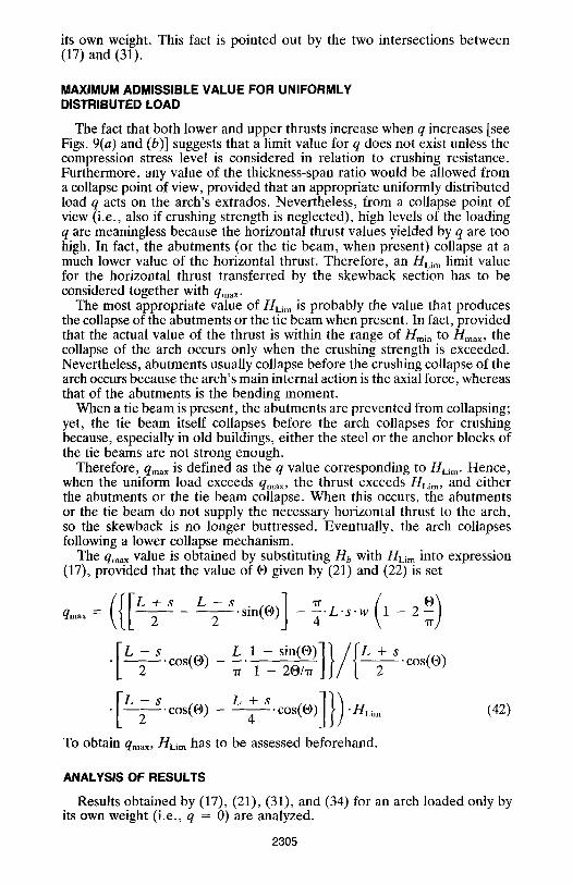
MAXIMUM ADMISSIBLE VALUE FOR UNIFORMLY DISTRIBUTED LOAD
The fact that both lower and upper thrusts increase when q increases [see Figs. 9(a) and (b)] suggests that a limit value for q does not exist unless the compression stress level is considered in relation to crushing resistance. Furthermore, any value of the thickness-span ratio would be allowed from a collapse point of view, provided that an appropriate uniformly distributed load q acts on the arch's extrados. Nevertheless, from a collapse point of view (i.e., also if crushing strength is neglected), high levels of the loading q are meaningless because the horizontal thrust values yielded by q are too high. In fact, the abutments (or the tie beam, when present) collapse at a much lower value of the horizontal thrust. Therefore, an HLim limit value for the horizontal thrust transferred by the skewback section has to be considered together with qmax.
The most appropriate value of HLi m is probably the value that produces the collapse of the abutments or the tie beam when present. In fact, provided that the actual value of the thrust is within the range of Hmi, to Hm,x, the collapse of the arch occurs only when the crushing strength is exceeded. Nevertheless, abutments usually collapse before the crushing collapse of the arch occurs because the arch's main internal action is the axial force, whereas that of the abutments is the bending moment.
When a tie beam is present, the abutments are prevented from collapsing; yet, the tie beam itself collapses before the arch collapses for crushing because, especially in old buildings, either the steel or the anchor blocks of the tie beams are not strong enough.
Therefore, qr~ax is defined as the q value corresponding to HLim- Hence, when the uniform load exceeds q . . . . the thrust exceeds HLim, and either the abutments or the tie beam collapse. When this occurs, the abutments or the tie beam do not supply the necessary horizontal thrust to the arch, so the skewback is no longer buttressed. Eventually, the arch collapses following a lower collapse mechanism.
The q .... value is obtained by substituting Hb with nLirn into expression (17), provided that the value of O given by (21) and (22) is set
((IL qm~x = 2 - - - - - - ~ . s i n ( O ) - - ~ . L ' s . w 1 - 2
cos o)
�9 [ L - - -
L 1 - s i n ( o ) l ] / f L + s , _ , -_ jl/l-- cos
L+4 sc~176 H-m To obtain qmax, nLim has to be assessed beforehand.
(42)
ANALYSIS OF RESULTS
Results obtained by (17), (21), (31), and (34) for an arch loaded only by its own weight (i.e., q = 0) are analyzed.
2305
The previous equations yielded a range of 30-35 ~ for O, independent of the parameters L, S, and w (Figs. 2 and 3). This result confirms the value of O = 30 ~ obtained by experience.
Therefore, the position of the hinge varies over a small range. And fur- thermore, (17) is quite flat in correspondence with its maximum; so for any value set within that range or just outside it, (17) always provides a lower thrust value that is similar to the one obtained using the actual angle.
This flat zone indicates that the hinge in the haunch is placed in the weakest radial section close to that yielded by (21). When the thickness- span ratio increases, the flat zone becomes wider and flatter.
In the case of the upper mechanism, and with q = 0, the hinge in the haunch formed an angle O between 35 ~ and 55 ~ (Figs. 5 and 6). Since (31) has a fiat minimum, whatever value of 19 within that range or near it yields a value of the upper thrust similar to that obtained using the correct angle. Again, the hinge in the haunch is placed in the weakest section close to that yielded by (34). For the upper thrust also, the flat zone increases when the thickness-span ratio increases.
If a uniformly distributed load q is applied in the case of the lower mechanism, a 30-37 ~ range is obtained for O, as shown in Fig. 9(a). There- fore, the 30 ~ value obtained by experience remains valid. The maximum of the curve is still flat, so similar considerations to those mentioned can be made about the possibility of approximating t9 in (17).
If a uniformly distributed load is applied, the upper mechanism largely depends on the value of q, as shown in Fig. 9(b). High values of q yield a range of possible values for the angle 19 of the hinge in the haunch ap- proximately equal to 30-35 ~ The 19 range becomes about 25-30 ~ for very high values of q.
Also in this case, the curves yielded by (31) are quite flat around the minimum, so the thrust value can be satisfactorily evaluated by using an approximate value of 19 in (31), instead of that provided by (34).
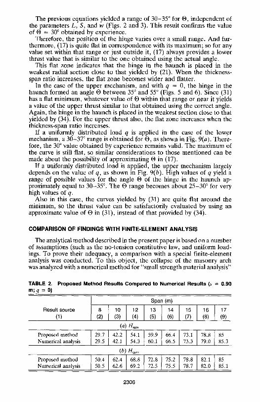
COMPARISON OF FINDINGS WITH FINITE-ELEMENT ANALYSIS
The analytical method described in the present paper is based on a number of assumptions (such as the no-tension constitutive law, and uniform load- ings. To prove their adequacy, a comparison with a special finite-element analysis was conducted. To this object, the collapse of the masonry arch was analyzed with a numerical method for "small strength material analysis"
TABLE 2. Proposed Method Results Compared to Numerical Results (s = 0.90 m;q = 0)
Result source (1)
Proposed method Numerical analysis
Proposed method Numerical analysis
Span (m)
(2) (4) (5) (7) (8) (9)
(a) Hmi . 9.714 . ,4.1,9.9160.4p7,.,1 ., , , 29.5 42.1 54.3 60.1 66.5 73 .3 79 .0 85.3
(b) H~ax
50"4 I 62"4 I 68'8 I 72"8 I 75"2 78"8182"1185 50.5 62 .6 69 .2 72 .5 75.5 78 .7 82 .0 85.1
2306
(Chiostrini et al. 1989). Only negligible differences turned out between both the limit thrusts (see Table 2) and the mechanisms when the actual weight's distribution of the fill; its thrusting behavior and its strength; and masonry small tensile strength were taken into account. Thus, the fill can be rep- resented by a uniform dead load without loss in accuracy. Moreover, no- tension constitutive model results are adequate. In addition, in most cases, the collapse mechanisms do not depend on the distribution of the incidental loads, provided that the loading is symmetrical. In fact, the amount of the incidental loads usually is small compared to that of the dead loads (the self weight of both the masonry arch and the supported structures, as well as the spandrel fill).
Referring to previous finite-element studies (Blasi and Foraboschi 1989a, 1989b), if arches of noncircular shape (however, with shape not much dif- ferent from the circular one) are replaced with an equivalent circular arch, that is, with the constant-thickness circular arch that best fits the given shape, negligible errors are produced in the collapse analysis.
CONCLUSIONS
When masonry buildings are investigated, it is of great significance to evaluate the collapse situations, since evaluating stresses and strains pro- duced by loads is a hard task. In fact, masonry structures are cracked by service loads, retaining an inelastic behavior for their entire existence; thus, an elastic approach is unrealistic, whereas a collapse approach can be more appropriate.
To perform nonlinear stress-strain analyses, special finite elements can be used that are capable of reproducing masonry mechanical behavior. Nevertheless, problems arise in the case of arches since the boundary con- ditions must be assessed taking into account the actual behavior of the abutments and all the structures connected to them. Therefore, a collapse approach provides more reliable results in the case of boundary conditions too complex and uncertain to be reliably modeled.
Moreover, a finite-element model capable of reproducing masonry-ma- terial mechanical properties quite frequently needs the calibration of its free parameters and the verification of its results. To this object also, analytical results provided by a collapse approach can be used since they can be compared with the corresponding results provided by the finite-element model.
The actual value of the thrust, and therefore of the arch's structural state, depend on the boundary conditions, in particular on the stiffness of the abutments, which varies due to cracking, creep, and other factors throughout the years. Thus, the limit situations can better represent the arch's structural state, as well as its safety margin, especially when the mechanisms do not differ too much.
APPENDIX I. REFERENCES
Benvenuto, E. (1981). The historical developments of the science of constructions. Sansoni Publisher, Rome, Italy, (in Italian).
Blasi, C., and Foraboschi, P. (1989a). "The masonry arch: a finite element approach by no-tension-friction-elements and check of the method." Proc., AIMETA, IV Italian Conf. on Computational Mech., Padova, Italy, (in Italian).
Blasi, C., and Foraboschi, P. (1989b). "A Non-linear finite element approach to the masonry arch and the masonry flat arch." Proc., Int. Tech. Conf. Struct. Conser- vation of Stone Masonry, DIC Athens, Greece.
2307
Castigliano, C. A. P. (1879). Theorie de l'equilibre des systemes elastiques et ses applications. A. F. Negro Publisher, Turin, Italy (in French).
Chiostrini, S., Foraboschi, P., and Sorace S. (1989). "Problems connected with the arrangement of a non-linear finite element method to the analysis of masonry structures." Proc., Int. Conf. STREMA, Florence, Italy.
Coulomb, C. A. (1773). "Essai sur une application des regles de maximis et minimis a quelques problemes de statique, relatifs a I'architecture." Memoires de mathe- matique et de physique presentes a l'Academie Royale des Sciences par divers savans, 7, Paris, France, 343-382 (in French).
Couplet, P. (1729). "De la poussee des voutes." Histoire de l'Academie Royale des Sciences, Paris, France (in French).
Couplet, P. (1730). "De la poussee des voutes." Histoire de l'Academie Royale des Sciences, Paris, France (in French).
Frezier, A. F. (1739). La theorie et la pratique de la coupe des pierres. Vol. 3, Paris, France (in French).
Fuller, G. (1875). Curve of equilibrium for a rigid arch under vertical forces. Proc., Inst. Civ. Engrg., 40, 143-164.
Heyman, J. (1966). "The stone skeleton." Int. J. Solid Structures, 2, 249-279. Heyman, J. (1969). "The safety of masonry arches." Int. J. Mechanics Sci., 11,363-
372. Heyman, J. (1980). "The estimation of the strength of masonry arches." Proc., Inst.
Cir. Engrg., Univ. of Cambridge, Cambridge, England, 69, 921. Heyman, J. (1982). The masonry arch. Ellis Horwood Series in Engrg. and Science,
John Wiley & Sons, New York, N.Y, Hooke, R. (1675). The true mathematical and mechanical form of all manner of
arches for building. University Press, London, England. de La Hire, P. (1695). Traite de mecanique. L'Academie Royale des Sciences, Paris,
France (in French), de La Hire, P. (1712). "Sur la construction des voutes dans le edificies." Memoires
de l'Academie Royale des Sciences, Paris, France (in French). Lame, M. G., and Clapeyron, E. (1823). "Memoires sur la stabilite des voutes."
Annales des Mines, 8,789 (in French). Mascheroni, L. (1785). New researches on the equilibrium of the domes. Pavia, Italy,
(in Italian). Mery, E. (1840). "Sur l'equilibre des voutes en herceu." Annales de Ponts et Chaus-
sess, Paris, France (in French). Navier, C. L. M. H. (1833). Resume des lecons donnees a l'Ecole des Ponts et
Chaussees, sur l' application de la mecanique a l'etablis sement des constructions et des machines. Paris, France (in French).
Poleni, G. (1748). Historical treatise on the great dome of vaticano temple. Padova, Italy, (in Italian).
"Structural monitoring of the Brunelleschi's Domes of the St. Maria del Fiore Church in Florence: results and interpretations." (1991). Civ. Engrg. Dept., Florence Univ., Florence, Italy (in Italian).
Villaggio, P. (1981). "Stress diffusion in masonry walls." J. Struct, Mech., 9(4), 159- 168.
Ware, S. (1809). A treatise of the properties of arches, and their abutments piers. London, England.
APPENDIX II. NOTATION
The following symbols are used in this paper:
[C] = elastic-deformability tensor; [D] = [C] - t ;
d~ = arm of Pv with respect to D; d2 = arm of Q,, with respect to D; E = masonry modulus of elasticity;
2308
HLIM
a~a, /-/~in
//~., Hg~
H(e) n;,(O)
K
L N
Nh P
Pv av
q
qmax R
r
S' S
t V W
E
Ec
Ee
[EJ EO
~e x
O o~
19
[,,]
O'Li m O" max
= horizontal thrust appl ied at point B of the section A B ; = maximum thrust value that does not produce collapse of
abutments or tie beam; = upper horizontal limit thrust appl ied at skewback; = lower horizontal l imit thrust appl ied at skewback; = lower and upper hor izonta l limit thrust obta ined according
to special f in i te-e lement analysis; = horizontal thrust when hinge in haunch forms an angle 0 ; = derivative of HB(@) with respect to (9; = adimensional coefficient depending on e; = adimensional coefficient depending on e; = arch's span ---- 2 . R = component of line of thrust normal to the cross section
(i .e . , axial force in arch); = axial force N in haunch cross section with hinge; = weight of half arch; = weight of A B C D block; = resultant of par t of q appl ied on BC; = uniformly dis t r ibuted load appl ied at extrados of arch; = maximum admissible value of uniform load = radius --= (L/2); = internal radius --- (R - s/2); = reduced thickness; = thickness of arch (constant) ; = depth of arch assumed as 1 (i .e. , uni tary depth) ; = vertical react ion at skewback provided by abutments ; = specific weight of masonry (force/length3); = distance of N with respect to in t rados or extrados; = strain (•e "}- e c ) ;
= strain tensor; = cracking strain; = inelastic par t of [el p roduced by mater ia l cracking; = elastic strain; = elastic par t of [el; = masonry yielding strain; = maximum principal stress of [ee] = minimum principal strain of [ec]; = angle of hinge in haunch to horizontal (in radians); = angle formed by each of two ext reme cross sections to the
horizontal (in radians); = | value provided by H i ( | = 0; = O value for which line of thrust passes through intrados
of skewback; = stress tensor; = masonry crushing strength; = maximum principal stress of [~]; and = safety margin of masonry arch under given load.
2309