Analytical and Experimental Investigation of Post ...
7
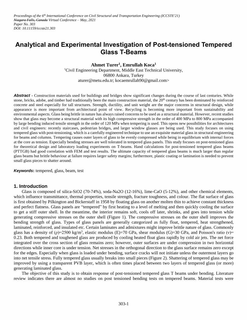
Proceedings of the 6 th International Conference on Civil Structural and Transportation Engineering (ICCSTE'21) Niagara Falls, Canada Virtual Conference – May, 2021 Paper No. 303 DOI: 10.11159/iccste21.303 303-1 Analytical and Experimental Investigation of Post-tensioned Tempered Glass T-Beams Ahmet Turer 1 , Emrullah Koca 1 1 Civil Engineering Department, Middle East Technical University, 06800 Ankara, Turkey [email protected]; [email protected]> Abstract - Construction materials used for buildings and bridges show significant changes during the course of last centuries. While stone, bricks, adobe, and timber had traditionally been the main construction material, the 20 th century has been dominated by reinforced concrete and steel especially for tall structures. Strength, ductility, and unit weight are the major concerns in structural design, while appearance is more important from architectural point of view. Recycling is becoming more important from sustainability and environmental aspects. Glass being brittle in nature has always raised concerns to be used as a structural material. However, recent studies show that glass may become a structural material with its high compressive strength in the order of 400 MPa to 800 MPa accompanied by large bending induced tensile strength in the order of 120 MPa when tempering is used. This opens new possibilities for architectures and civil engineers: recently staircases, pedestrian bridges, and larger window glasses are being used. This study focuses on using tempered glass with post-tensioning, which is a carefully engineered technique to use an exquisite material glass in structural engineering for beams and columns. Tempering causes outer layers of glass to be evenly compressed while being in equilibrium with internal forces at the core as tension. Especially bending stresses are well tolerated in tempered glass panels. This study focuses on post-tensioned glass for theoretical design and laboratory loading experiments on T-beams. Hand calculations for post-tensioned tempered glass beams (PTTGB) had good correlation with FEM and test results. The ultimate capacity of tempered glass beams is much larger than regular glass beams but brittle behaviour at failure requires larger safety margins; furthermore, plastic coating or lamination is needed to prevent small glass pieces to shatter around. Keywords: tempered, glass, beam, test 1. Introduction Glass is composed of silica-SiO2 (70-74%), soda-Na2O (12-16%), lime-CaO (5-12%), and other chemical elements, which influence transmittance, thermal properties, tensile strength, fracture toughness, and colour. The flat surface of glass is first obtained by Pilkington and Bickerstaff in 1958 by floating glass on another molten thin to achieve constant thickness and perfect flatness. Glass panels are “tempered” by first heating to a level of melting and then quickly cooling the surface to get a stiff outer shell. In the meantime, the interior remains soft, cools off later, shrinks, and goes into tension while generating compressive stresses on the outer shell (Figure 1). The compressive stresses on the outer shell improves the bending strength of glass. Types of glass panels are generally categorized as fully float, tempered, heat strengthened, laminated, reinforced, and insulated etc. Certain laminates and admixtures might improve brittle nature of glass. Commonly glass has a density of (ρ)=2500 kg/m 3 , elastic modulus (E)=70 GPa, shear modulus (G)=30 GPa, and Poisson's ratio (ν)= 0.23. Both tempered and toughened glass are produced by cooling heated float glass rapidly by cold air jets. The net force integrated over the cross section of glass remains zero; however, outer surfaces are under compression in two horizontal directions while inner core is under tension. Net stresses in the orthogonal direction to the glass surface remains zero except for the edges. Especially when glass is loaded under bending, surface cracks will not initiate unless the outermost layers go into net tensile stress. Fully tempered glass usually breaks into small pieces (Figure 2). Shattering of tempered glass may be improved by using a transparent PVB layer, which is often times placed between two layers of tempered glass (or more) generating laminated glass. The objective of this study is to obtain response of post-tensioned tempered glass T beams under bending. Literature review indicates there are almost no studies on post tensioned bending tests on tempered beams. Material tests were
Transcript of Analytical and Experimental Investigation of Post ...
Proceedings of the 6th International Conference on Civil Structural and Transportation Engineering (ICCSTE'21)
Niagara Falls, Canada Virtual Conference – May, 2021
Paper No. 303
DOI: 10.11159/iccste21.303
303-1
Analytical and Experimental Investigation of Post-tensioned Tempered Glass T-Beams
Ahmet Turer1, Emrullah Koca1 1Civil Engineering Department, Middle East Technical University,
06800 Ankara, Turkey
[email protected]; [email protected]>
Abstract - Construction materials used for buildings and bridges show significant changes during the course of last centuries. While
stone, bricks, adobe, and timber had traditionally been the main construction material, the 20th century has been dominated by reinforced
concrete and steel especially for tall structures. Strength, ductility, and unit weight are the major concerns in structural design, while
appearance is more important from architectural point of view. Recycling is becoming more important from sustainability and
environmental aspects. Glass being brittle in nature has always raised concerns to be used as a structural material. However, recent studies
show that glass may become a structural material with its high compressive strength in the order of 400 MPa to 800 MPa accompanied
by large bending induced tensile strength in the order of 120 MPa when tempering is used. This opens new possibilities for architectures
and civil engineers: recently staircases, pedestrian bridges, and larger window glasses are being used. This study focuses on using
tempered glass with post-tensioning, which is a carefully engineered technique to use an exquisite material glass in structural engineering
for beams and columns. Tempering causes outer layers of glass to be evenly compressed while being in equilibrium with internal forces
at the core as tension. Especially bending stresses are well tolerated in tempered glass panels. This study focuses on post-tensioned glass
for theoretical design and laboratory loading experiments on T-beams. Hand calculations for post-tensioned tempered glass beams
(PTTGB) had good correlation with FEM and test results. The ultimate capacity of tempered glass beams is much larger than regular
glass beams but brittle behaviour at failure requires larger safety margins; furthermore, plastic coating or lamination is needed to prevent
small glass pieces to shatter around.
Keywords: tempered, glass, beam, test
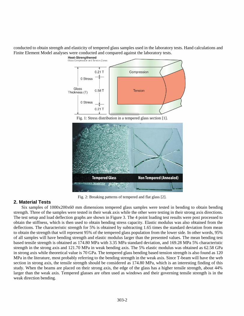
1. Introduction Glass is composed of silica-SiO2 (70-74%), soda-Na2O (12-16%), lime-CaO (5-12%), and other chemical elements,
which influence transmittance, thermal properties, tensile strength, fracture toughness, and colour. The flat surface of glass
is first obtained by Pilkington and Bickerstaff in 1958 by floating glass on another molten thin to achieve constant thickness
and perfect flatness. Glass panels are “tempered” by first heating to a level of melting and then quickly cooling the surface
to get a stiff outer shell. In the meantime, the interior remains soft, cools off later, shrinks, and goes into tension while
generating compressive stresses on the outer shell (Figure 1). The compressive stresses on the outer shell improves the
bending strength of glass. Types of glass panels are generally categorized as fully float, tempered, heat strengthened,
laminated, reinforced, and insulated etc. Certain laminates and admixtures might improve brittle nature of glass. Commonly
glass has a density of (ρ)=2500 kg/m3, elastic modulus (E)=70 GPa, shear modulus (G)=30 GPa, and Poisson's ratio (ν)=
0.23. Both tempered and toughened glass are produced by cooling heated float glass rapidly by cold air jets. The net force
integrated over the cross section of glass remains zero; however, outer surfaces are under compression in two horizontal
directions while inner core is under tension. Net stresses in the orthogonal direction to the glass surface remains zero except
for the edges. Especially when glass is loaded under bending, surface cracks will not initiate unless the outermost layers go
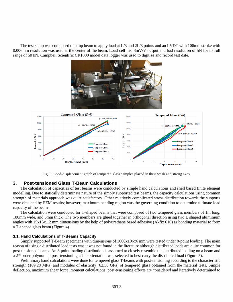
into net tensile stress. Fully tempered glass usually breaks into small pieces (Figure 2). Shattering of tempered glass may be
improved by using a transparent PVB layer, which is often times placed between two layers of tempered glass (or more)
generating laminated glass.
The objective of this study is to obtain response of post-tensioned tempered glass T beams under bending. Literature
review indicates there are almost no studies on post tensioned bending tests on tempered beams. Material tests were
303-2
conducted to obtain strength and elasticity of tempered glass samples used in the laboratory tests. Hand calculations and
Finite Element Model analyses were conducted and compared against the laboratory tests.
Fig. 1: Stress distribution in a tempered glass section [1].
Fig. 2: Breaking patterns of tempered and flat glass [2].
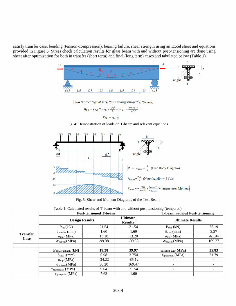
2. Material Tests Six samples of 1000x200x60 mm dimensions tempered glass samples were tested in bending to obtain bending
strength. Three of the samples were tested in their weak axis while the other were testing in their strong axis directions.
The test setup and load deflection graphs are shown in Figure 3. The 4 point loading test results were post processed to
obtain the stiffness, which is then used to obtain bending stress capacity. Elastic modulus was also obtained from the
deflections. The characteristic strength for 5% is obtained by subtracting 1.65 times the standard deviation from mean
to obtain the strength that will represent 95% of the tempered glass population from the lower side. In other words, 95%
of all samples will have bending strength and elastic modulus larger than the presented values. The mean bending test
based tensile strength is obtained as 174.80 MPa with 3.35 MPa standard deviation, and 169.28 MPa 5% characteristic
strength in the strong axis and 121.70 MPa in weak bending axis. The 5% elastic modulus was obtained as 62.58 GPa
in strong axis while theoretical value is 70 GPa. The tempered glass bending based tension strength is also found as 120
MPa in the literature, most probably referring to the bending strength in the weak axis. Since T-beam will have the web
section in strong axis, the tensile strength should be considered as 174.80 MPa, which is an interesting finding of this
study. When the beams are placed on their strong axis, the edge of the glass has a higher tensile strength, about 44%
larger than the weak axis. Tempered glasses are often used as windows and their governing tensile strength is in the
weak direction bending.
303-3
The test setup was composed of a top beam to apply load at L/3 and 2L/3 points and an LVDT with 100mm stroke with
0.006mm resolution was used at the center of the beam. Load cell had 3mV/V output and had resolution of 5N for its full
range of 50 kN. Campbell Scientific CR1000 model data logger was used to digitize and record test date.
Fig. 3: Load-displacement graph of tempered glass samples placed in their weak and strong axes.
3. Post-tensioned Glass T-Beam Calculations The calculation of capacities of test beams were conducted by simple hand calculations and shell based finite element
modelling. Due to statically determinate nature of the simply supported test beams, the capacity calculations using common
strength of materials approach was quite satisfactory. Other relatively complicated stress distribution towards the supports
were obtained by FEM results; however, maximum bending region was the governing condition to determine ultimate load
capacity of the beams.
The calculation were conducted for T-shaped beams that were composed of two tempered glass members of 1m long,
100mm wide, and 6mm thick. The two members are glued together in orthogonal direction using two L shaped aluminium
angles with 15x15x1.2 mm dimensions by the help of polyurethane based adhesive (Akfix 610) as bonding material to form
a T-shaped glass beam (Figure 4).
3.1. Hand Calculations of T-Beams Capacity
Simply supported T-Beam specimens with dimensions of 1000x106x6 mm were tested under 8-point loading. The main
reason of using a distributed load tests was it was not found in the literature although distributed loads are quite common for
post-tensioned beams. An 8-point loading distribution is assumed to closely resemble the distributed loading on a beam and
a 2nd order polynomial post-tensioning cable orientation was selected to best carry the distributed load (Figure 5).
Preliminary hand calculations were done for tempered glass T-beams with post-tensioning according to the characteristic
strength (169.28 MPa) and modulus of elasticity (62.58 GPa) of tempered glass obtained from the material tests. Simple
deflection, maximum shear force, moment calculations, post-tensioning effects are considered and iteratively determined to
303-4
satisfy transfer case, bending (tension-compression), bearing failure, shear strength using an Excel sheet and equations
provided in Figure 5. Stress check calculation results for glass beam with and without post-tensioning are done using
sheet after optimization for both in transfer (short term) and final (long term) cases and tabulated below (Table 1).
Fig. 4: Demonstration of loads on T-beam and relevant equations.
Fig. 5: Shear and Moment Diagrams of the Test Beam.
Table 1: Calculated results of T-beam with and without post tensioning (tempered).
Post-tensioned T-beam T-beam without Post-tensioning
Design Results Ultimate
Results Ultimate Results
PPR (kN) 21.54 21.54 Pmax (kN) 25.19
Transfer
Case
δtransfer (mm) 1.60 1.60 δmax (mm) 3.37
𝜎top (MPa) 13.20 13.20 𝜎top (MPa) -61.94
𝜎bottom (MPa) -99.38 -99.38 𝜎bottom (MPa) 169.27
Pdes./crack/ult. (kN) 19.28 39.97 τneutral axis (MPa) 25.83
δfinal (mm) 0.98 3.754 τglue point (MPa) 21.79
𝜎top (MPa) -34.22 -85.12 - -
𝜎bottom (MPa) 30.20 169.47 - -
τneutral axis (MPa) 9.04 21.54 - -
τglue point (MPa) 7.63 1.60 - -
303-5
As seen in the table, the load carrying capacity of the beam is increased by about 1.6 times (increased from 25.19 kN to
39.97 kN) the original case without post-tensioning.
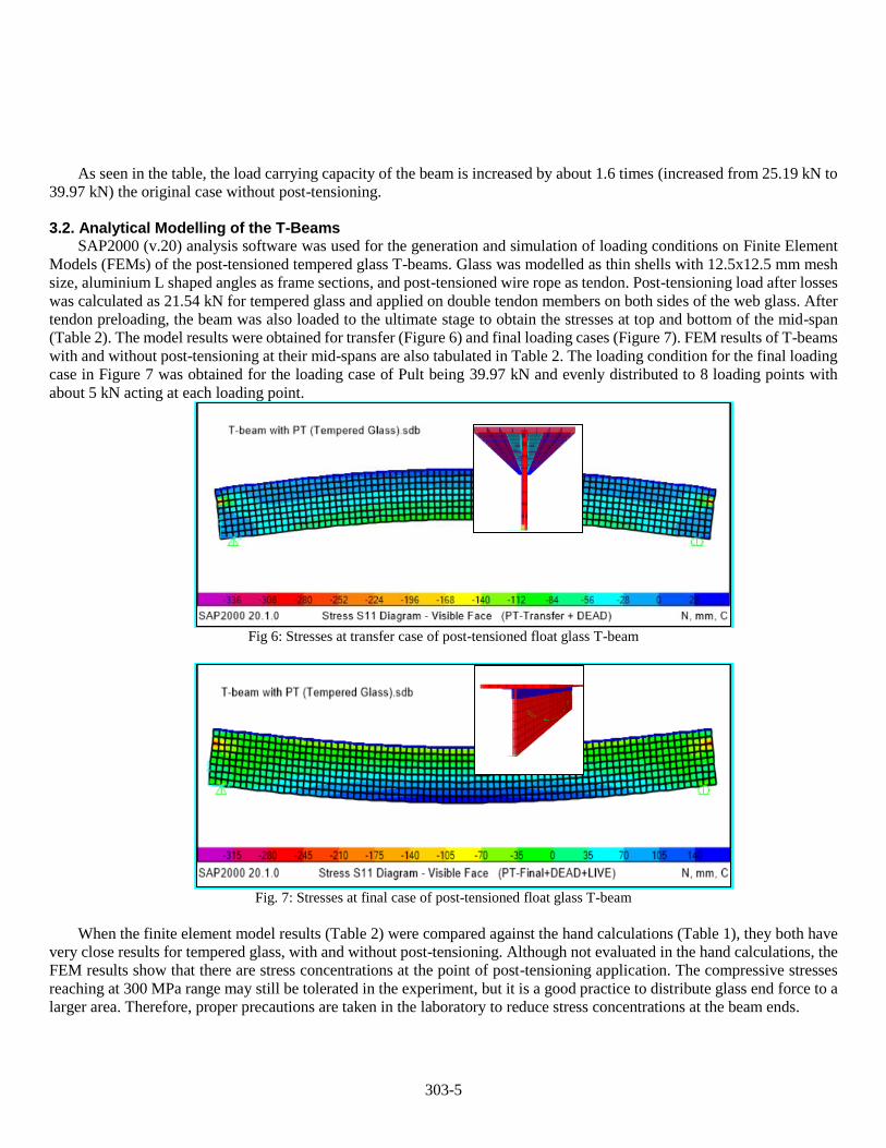
3.2. Analytical Modelling of the T-Beams
SAP2000 (v.20) analysis software was used for the generation and simulation of loading conditions on Finite Element
Models (FEMs) of the post-tensioned tempered glass T-beams. Glass was modelled as thin shells with 12.5x12.5 mm mesh
size, aluminium L shaped angles as frame sections, and post-tensioned wire rope as tendon. Post-tensioning load after losses
was calculated as 21.54 kN for tempered glass and applied on double tendon members on both sides of the web glass. After
tendon preloading, the beam was also loaded to the ultimate stage to obtain the stresses at top and bottom of the mid-span
(Table 2). The model results were obtained for transfer (Figure 6) and final loading cases (Figure 7). FEM results of T-beams
with and without post-tensioning at their mid-spans are also tabulated in Table 2. The loading condition for the final loading
case in Figure 7 was obtained for the loading case of Pult being 39.97 kN and evenly distributed to 8 loading points with
about 5 kN acting at each loading point.
Fig 6: Stresses at transfer case of post-tensioned float glass T-beam
Fig. 7: Stresses at final case of post-tensioned float glass T-beam
When the finite element model results (Table 2) were compared against the hand calculations (Table 1), they both have
very close results for tempered glass, with and without post-tensioning. Although not evaluated in the hand calculations, the
FEM results show that there are stress concentrations at the point of post-tensioning application. The compressive stresses
reaching at 300 MPa range may still be tolerated in the experiment, but it is a good practice to distribute glass end force to a
larger area. Therefore, proper precautions are taken in the laboratory to reduce stress concentrations at the beam ends.
303-6
Table 2: FEM results of T-beam with and without post tensioning
T-beams without PT T-beams with PT
Transfer Case Final Case
δmax (mm) 3.64 1.84 3.92
𝜎max,tensile (MPa) 171.3 12.86 169.3
𝜎max,compressive (MPa) -68.25 -103.3 -95.9
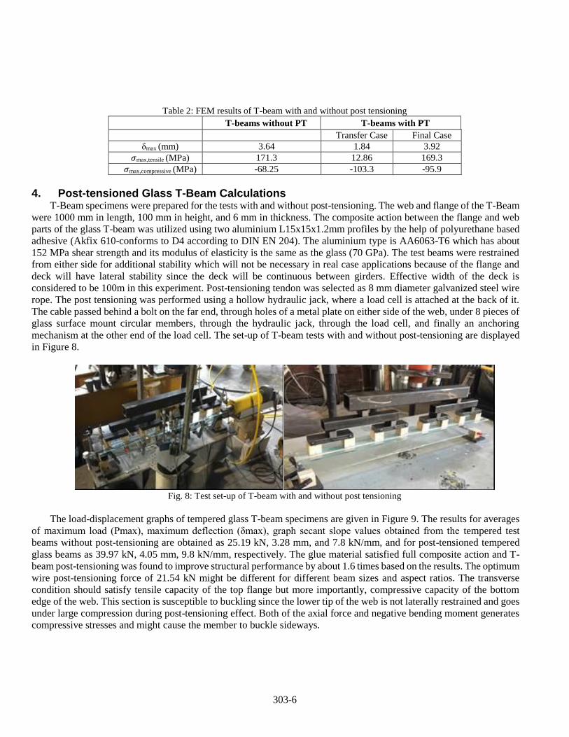
4. Post-tensioned Glass T-Beam Calculations T-Beam specimens were prepared for the tests with and without post-tensioning. The web and flange of the T-Beam
were 1000 mm in length, 100 mm in height, and 6 mm in thickness. The composite action between the flange and web
parts of the glass T-beam was utilized using two aluminium L15x15x1.2mm profiles by the help of polyurethane based
adhesive (Akfix 610-conforms to D4 according to DIN EN 204). The aluminium type is AA6063-T6 which has about
152 MPa shear strength and its modulus of elasticity is the same as the glass (70 GPa). The test beams were restrained
from either side for additional stability which will not be necessary in real case applications because of the flange and
deck will have lateral stability since the deck will be continuous between girders. Effective width of the deck is
considered to be 100m in this experiment. Post-tensioning tendon was selected as 8 mm diameter galvanized steel wire
rope. The post tensioning was performed using a hollow hydraulic jack, where a load cell is attached at the back of it.
The cable passed behind a bolt on the far end, through holes of a metal plate on either side of the web, under 8 pieces of
glass surface mount circular members, through the hydraulic jack, through the load cell, and finally an anchoring
mechanism at the other end of the load cell. The set-up of T-beam tests with and without post-tensioning are displayed
in Figure 8.
Fig. 8: Test set-up of T-beam with and without post tensioning
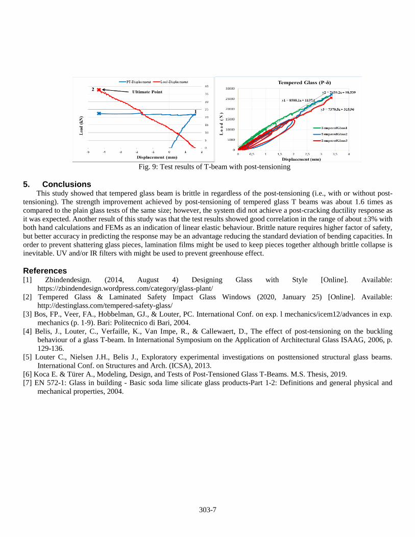
The load-displacement graphs of tempered glass T-beam specimens are given in Figure 9. The results for averages
of maximum load (Pmax), maximum deflection (δmax), graph secant slope values obtained from the tempered test
beams without post-tensioning are obtained as 25.19 kN, 3.28 mm, and 7.8 kN/mm, and for post-tensioned tempered
glass beams as 39.97 kN, 4.05 mm, 9.8 kN/mm, respectively. The glue material satisfied full composite action and T-
beam post-tensioning was found to improve structural performance by about 1.6 times based on the results. The optimum
wire post-tensioning force of 21.54 kN might be different for different beam sizes and aspect ratios. The transverse
condition should satisfy tensile capacity of the top flange but more importantly, compressive capacity of the bottom
edge of the web. This section is susceptible to buckling since the lower tip of the web is not laterally restrained and goes
under large compression during post-tensioning effect. Both of the axial force and negative bending moment generates
compressive stresses and might cause the member to buckle sideways.
303-7
Fig. 9: Test results of T-beam with post-tensioning
5. Conclusions This study showed that tempered glass beam is brittle in regardless of the post-tensioning (i.e., with or without post-
tensioning). The strength improvement achieved by post-tensioning of tempered glass T beams was about 1.6 times as
compared to the plain glass tests of the same size; however, the system did not achieve a post-cracking ductility response as
it was expected. Another result of this study was that the test results showed good correlation in the range of about ±3% with
both hand calculations and FEMs as an indication of linear elastic behaviour. Brittle nature requires higher factor of safety,
but better accuracy in predicting the response may be an advantage reducing the standard deviation of bending capacities. In
order to prevent shattering glass pieces, lamination films might be used to keep pieces together although brittle collapse is
inevitable. UV and/or IR filters with might be used to prevent greenhouse effect.
References [1] Zbindendesign. (2014, August 4) Designing Glass with Style [Online]. Available:
https://zbindendesign.wordpress.com/category/glass-plant/
[2] Tempered Glass & Laminated Safety Impact Glass Windows (2020, January 25) [Online]. Available:
http://destinglass.com/tempered-safety-glass/
[3] Bos, FP., Veer, FA., Hobbelman, GJ., & Louter, PC. International Conf. on exp. l mechanics/icem12/advances in exp.
mechanics (p. 1-9). Bari: Politecnico di Bari, 2004.
[4] Belis, J., Louter, C., Verfaille, K., Van Impe, R., & Callewaert, D., The effect of post-tensioning on the buckling
behaviour of a glass T-beam. In International Symposium on the Application of Architectural Glass ISAAG, 2006, p.
129-136.
[5] Louter C., Nielsen J.H., Belis J., Exploratory experimental investigations on posttensioned structural glass beams.
International Conf. on Structures and Arch. (ICSA), 2013.
[6] Koca E. & Türer A., Modeling, Design, and Tests of Post-Tensioned Glass T-Beams. M.S. Thesis, 2019.
[7] EN 572-1: Glass in building - Basic soda lime silicate glass products-Part 1-2: Definitions and general physical and
mechanical properties, 2004.