Analysis of VSC-HVDC System Stability with Protective · PDF fileAnalysis of VSC-HVDC System...
4
Analysis of VSC-HVDC System Stability with Protective Reactors Hui Li 1 , Jun Liang 2 , Ming Xiong 1 , and Li Zhang 1 1 School of Automation, Beijing Information Science & Technology University, Beijing, China 2 School of Engineering, Cardiff University, Cardiff, UK Email: [email protected], [email protected], {xiong54ming, zzrzl}@163.com Abstract—The use of Voltage Source Converter based High Voltage Direct Current (VSC-HVDC) links is considered a major step in facilitating long distance power transfer and integrating renewable energy sources. The introduction of protective reactors throughout such systems can have significant impact on their stable operations. Therefore, a stability study in VSC-HVDC systems is necessary. This paper proposes a method to analytically describe a two- terminal VSC-HVDC link with respect to its eigenvalues. The results from dynamic simulations using PSCAD show that large protective reactors can result in system stability problem, and the suggestion is provided to develop a novel variable dc reactor in the summary. Index Terms—VSC-HVDC, dc-network stability, protective reactor I. INTRODUCTION Over last decade, the power engineering society is showing an increasing interest in Voltage Source Converter based High Voltage Direct Current (VSC- HVDC) technology because of its specific controllability feature [1]. Development of Modular Multilevel Converter (MMC) has made VSC-HVDC more competitive in large power transmission due to its advantages of modular design, low switching frequency, high efficiency, and excellent output voltage waveforms [2]. Meantime, the VSC technology makes the extension to multi-terminal HVDC connections (MTDC) relatively easy. MTDC grids could form the backbone of a pan- European interconnected system in future [3] because it can offer more additional controllability compared to the two-terminal VSC-HVDC system [4]. However, the development of VSC-HVDC networks is constrained by the lack of operational experience, the immaturity of appropriate protective devices, and the lack of appropriate fault analysis techniques [5]. DC fault protection and dc circuit breakers (DCCBs) are the major challenge for developing a dc grid. An ac-side switchgear is not considered fast enough to cope with the rapid rise of fault current characteristic of freewheel diode condition which can damage power-electronic devices in several milliseconds. Manuscript received June 1, 2015; revised January 25, 2016. In fact, dc reactor is preferable to limit dc fault current [6]. The minimum size of the dc reactor depends on the breaking time of the DCCB, and its maximum current breaking rating, which is directly linked with the cost of the breaker. On the other hand, the dc reactor size is also limited by its cost, and possibly, the extra conduction loss and stability requirement of the dc grid. Reference [7] proposes a 6.5mH protective inductor design for the onshore and offshore converters, but only analyzes the transient characteristic of the transmission system under the cable-to-ground fault. Values in the order of 100mH per pole for ±320kV systems are typically used in previous published work [8]. Reference [9] proposes the design of a 400mH 400A toroid-type high temperature superconductor dc reactor magnet which has some advantages such as high current density, low electrical loss, and so on. However, large dc reactors require large footprint which is particularly difficult for offshore application. Presence of large inductance extends the electrical distance between converter stations, which has a detrimental effect on the dc voltage control, and the stability of HVDC grids. The aim of this paper is to propose a method to analysis dc-network stability in a two-terminal VSC- HVDC system because of large protective reactors. The presented method acts on the state space description of the system and derives the eigenvalues of the system in fully symbolic expressions. Mathematical analysis and dynamic simulations testify that large inductance of protective reactor results in significant impact on the VSC-HVDC system steady operation. II. STABILITY ANALYSIS IN A VSC-HVDC SYSTEM WITH PROTECTIVE REACTOR A. Mathematical Description of a VSC-HVDC System The system under consideration is a two-terminal symmetrical monopole VSC-HVDC link, as in Fig. 1(a). The connection is comprised of two VSC stations, as well as ac and dc side components. Each station is assumed to be connected to a strong ac grid, which can therefore be modeled as a voltage source. The connection of a VSC converter to its respective ac grid is normally performed via a coupling inductor and step-up transformer. Assuming that these components are lossless, they can be represented by a single inductor combining their International Journal of Electronics and Electrical Engineering Vol. 4, No. 5, October 2016 ©2016 Int. J. Electron. Electr. Eng. 408 doi: 10.18178/ijeee.4.5.408-411
Transcript of Analysis of VSC-HVDC System Stability with Protective · PDF fileAnalysis of VSC-HVDC System...
Analysis of VSC-HVDC System Stability with
Protective Reactors
Hui Li1, Jun Liang
2, Ming Xiong
1, and Li Zhang
1
1School of Automation, Beijing Information Science & Technology University, Beijing, China
2School of Engineering, Cardiff University, Cardiff, UK
Email: [email protected], [email protected], {xiong54ming, zzrzl}@163.com
Abstract—The use of Voltage Source Converter based High
Voltage Direct Current (VSC-HVDC) links is considered a
major step in facilitating long distance power transfer and
integrating renewable energy sources. The introduction of
protective reactors throughout such systems can have
significant impact on their stable operations. Therefore, a
stability study in VSC-HVDC systems is necessary. This
paper proposes a method to analytically describe a two-
terminal VSC-HVDC link with respect to its eigenvalues.
The results from dynamic simulations using PSCAD show
that large protective reactors can result in system stability
problem, and the suggestion is provided to develop a novel
variable dc reactor in the summary.
Index Terms—VSC-HVDC, dc-network stability, protective
reactor
I. INTRODUCTION
Over last decade, the power engineering society is
showing an increasing interest in Voltage Source
Converter based High Voltage Direct Current (VSC-
HVDC) technology because of its specific controllability
feature [1]. Development of Modular Multilevel
Converter (MMC) has made VSC-HVDC more
competitive in large power transmission due to its
advantages of modular design, low switching frequency,
high efficiency, and excellent output voltage waveforms
[2]. Meantime, the VSC technology makes the extension
to multi-terminal HVDC connections (MTDC) relatively
easy. MTDC grids could form the backbone of a pan-
European interconnected system in future [3] because it
can offer more additional controllability compared to the
two-terminal VSC-HVDC system [4].
However, the development of VSC-HVDC networks is
constrained by the lack of operational experience, the
immaturity of appropriate protective devices, and the lack
of appropriate fault analysis techniques [5]. DC fault
protection and dc circuit breakers (DCCBs) are the major
challenge for developing a dc grid. An ac-side switchgear
is not considered fast enough to cope with the rapid rise
of fault current characteristic of freewheel diode
condition which can damage power-electronic devices in
several milliseconds.
Manuscript received June 1, 2015; revised January 25, 2016.
In fact, dc reactor is preferable to limit dc fault current
[6]. The minimum size of the dc reactor depends on the
breaking time of the DCCB, and its maximum current
breaking rating, which is directly linked with the cost of
the breaker. On the other hand, the dc reactor size is also
limited by its cost, and possibly, the extra conduction loss
and stability requirement of the dc grid. Reference [7]
proposes a 6.5mH protective inductor design for the
onshore and offshore converters, but only analyzes the
transient characteristic of the transmission system under
the cable-to-ground fault. Values in the order of 100mH
per pole for ±320kV systems are typically used in
previous published work [8]. Reference [9] proposes the
design of a 400mH 400A toroid-type high temperature
superconductor dc reactor magnet which has some
advantages such as high current density, low electrical
loss, and so on. However, large dc reactors require large
footprint which is particularly difficult for offshore
application. Presence of large inductance extends the
electrical distance between converter stations, which has
a detrimental effect on the dc voltage control, and the
stability of HVDC grids.
The aim of this paper is to propose a method to
analysis dc-network stability in a two-terminal VSC-
HVDC system because of large protective reactors. The
presented method acts on the state space description of
the system and derives the eigenvalues of the system in
fully symbolic expressions. Mathematical analysis and
dynamic simulations testify that large inductance of
protective reactor results in significant impact on the
VSC-HVDC system steady operation.
II. STABILITY ANALYSIS IN A VSC-HVDC SYSTEM
WITH PROTECTIVE REACTOR
A. Mathematical Description of a VSC-HVDC System
The system under consideration is a two-terminal
symmetrical monopole VSC-HVDC link, as in Fig. 1(a).
The connection is comprised of two VSC stations, as well
as ac and dc side components. Each station is assumed to
be connected to a strong ac grid, which can therefore be
modeled as a voltage source. The connection of a VSC
converter to its respective ac grid is normally performed
via a coupling inductor and step-up transformer.
Assuming that these components are lossless, they can be
represented by a single inductor combining their
International Journal of Electronics and Electrical Engineering Vol. 4, No. 5, October 2016
©2016 Int. J. Electron. Electr. Eng. 408doi: 10.18178/ijeee.4.5.408-411
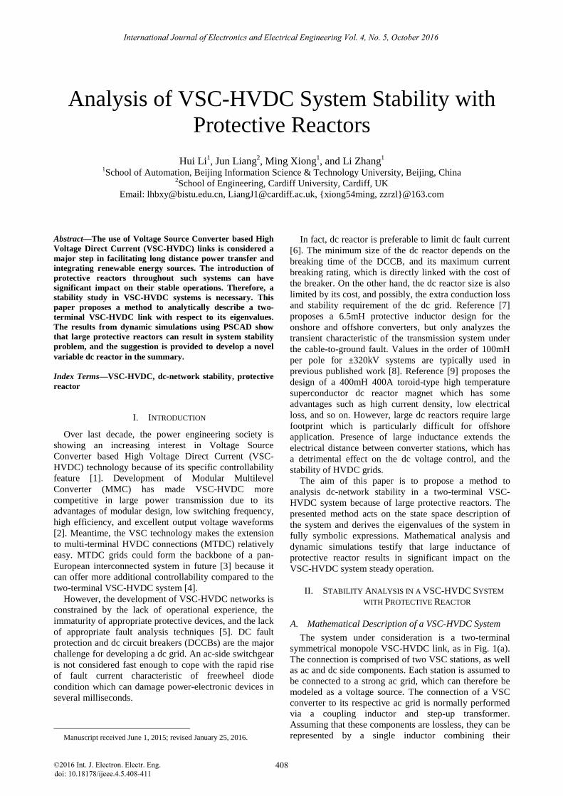
inductances. In Fig. 1(a), if power is transmitted from
Station 1 to Station 2, Station 1 is a dc-voltage controlled
station and Station 2 is active-power controlled.
The dc terminals of each station are connected to dc
capacitors whose middle point is ground. For simplifying
the analysis, each dc cable is modeled as a series
connection of a resistance and an inductance, with values
that are proportional to the length of the cable. Given the
physical characteristic of the symmetrical monopole
configuration and considering balanced conditions, the
model in Fig. 1(a) can be equated to the asymmetrical
monopole model in Fig. 1(b).
~ ~
Station 1 Station 2
Vdc control Active power
control
Power flow direction
L Rdc Ldc L
L LRdc Ldc
2Cdc
2Cdc
2Cdc
2Cdc
(a) Symmetrical model
~ ~
Station 1 Station 2
2L 2Rdc 2Ldc 2L
Cdc Cdcvdc1 vdc2
idc Pout
(b) Equivalent asymmetrical model
Figure 1. Two-Terminal monopole VSC-HVDC system
the active-power controlled VSC acts as an ideal power
source delivered power Pout to the ac side. We only
consider the dynamic of the active-power controller in
Station 2 when delivered power Pout is changed. The dc-
cable dynamics are provided as in (1):
d(2 4 ) 2
ddc dc dc1 dc2 dc dc
L L i v v R it
d 1(- 2 )
d (2 4 )dc dc2 dc dc
dc
i v R it L L
(1)
While the dynamics of the dc capacitor located at the
terminals of the power controlled station will be written
in (2):
d
d
out
dc dc2 dc
dc2
PC v i
t v
2
2,0 2,0
d 1 1( )
d
out,0
dc2 dc dc2 out
dc dc dc
Pv i u P
t C v v (2)
Considering the state 1 dc
x i , 2 dc2
x u , as well as
inputs 1 out
u P , the state matrix A of the resulting state-
space model is described by expressed in (3):
2
2,0 t,0
2 1
2 4 2 4
1 1
/
dc
dc dc
dc dc dc ou
R
L L L LA
C C v P
(3)
B. Analysis of a Simplified System
The rated parameters of the VSC-HVDC link are
presented in Table I. Substituting the nominal values of
Table I, in matrix A Rdc=3.84Ω, Ldc=0.048H, Cdc=50μF,
Vdc2,0=320kV, Pout,0=240MW. When the value of reactor
L is changed, the eigenvalues of the state-space model are
followed, as shown in Fig. 2.
TABLE I. RATED PARAMETERS OF THE VSC-HVDC LINK IN FIG. 1
Pout,0 Rated active power 240WM
Vdc2,0 Rated dc voltage 320kV
Cdc Shunt capacitor 50μF
r Dc cable resistance per km 0.0192Ω/km
l Dc cable inductance per km 0.24mH/km
length Cable line length 200km
-25 -20 -15 -10 -5 0 5100
150
200
250
300
350
400
10mH
20mH
40mH
60mH
80mH
100mH
120mH
150mH
200mH
Figure 2. Comparison of eigenvalues in the instance of different L
As shown in Fig. 2, when the value of L is less than
150mH, the system is still steady. But when the value of
L is more than 150mH, the system is not steady. Along
with the value of L from small to large, the real part of
eigenvalue is changed from negative to positive. This
means the system losses steady if reactance is increased
to some large value.
International Journal of Electronics and Electrical Engineering Vol. 4, No. 5, October 2016
©2016 Int. J. Electron. Electr. Eng. 409
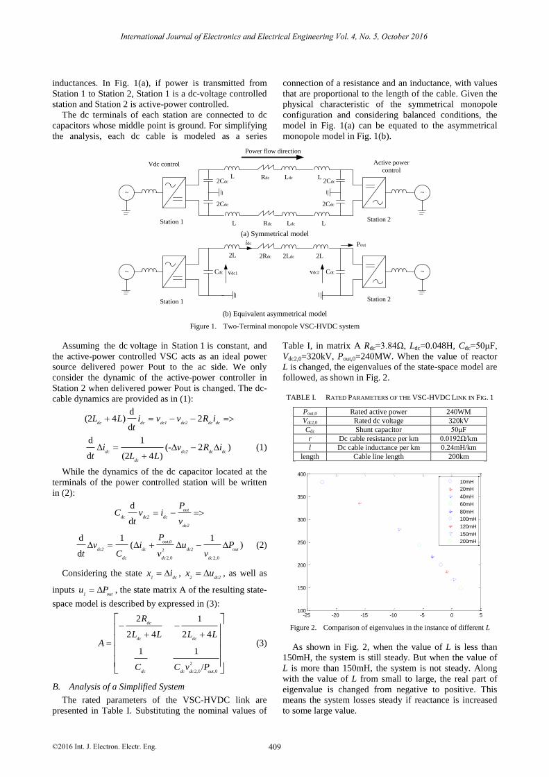
Assuming the dc voltage in Station 1 is constant, and
If the reactance is constant, we change Pout,0 and check
the system dynamics performance. Fig. 3(a) is the
eigenvalue result when L=60mH, and Fig. 3(b) is the
eigenvalue result when L=100mH.
-10 -8 -6 -4 -2 0 2242.8
242.9
243
243.1
243.2
243.3
243.4
243.5
243.6
243.7
100MW
200MW
240MW
300MW
350MW
400MW
450MW
500MW
(a) L=60mH
-6 -4 -2 0 2 4 6199.8
199.9
200
200.1
200.2
200.3
200.4
200.5
200.6
200.7
100MW
200MW
240MW
300MW
350MW
400MW
450MW
500MW
(b) L=100mH
Figure 3. Comparison of eigenvalues at different delivered active powers
As shown in Fig. 3(a), when the delivered active power
is more than 450MW, the system losses steady and the
eigenvalue is positive. But in Fig. 3(b), when the
delivered active power is more than 350MW, the system
losses steady. This shows that the reactor decides the
dynamic performance of VSC-HVDC systems when
delivered active power is changed. Once the delivered
active power is large, small reactance is needed to keep
the system stability.
III. DYNAMIC SIMULATION IN A VSC-HVDC SYSTEM
WITH PROTECTIVE REACTORS
In this section, the tests of dynamic simulations using
PSCAD/EMTDC are done by changing delivered active
power increasing 20% to check the pole current transient
performance at different inductance values.
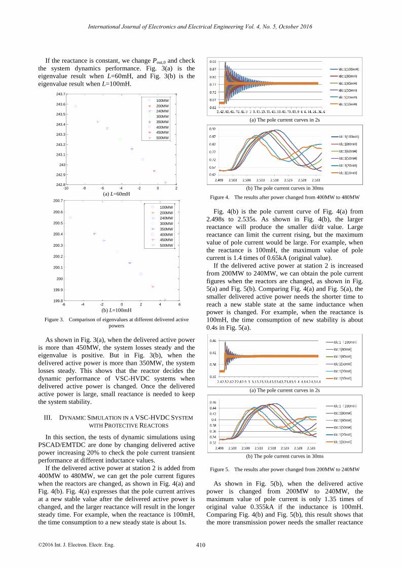
If the delivered active power at station 2 is added from
400MW to 480MW, we can get the pole current figures
when the reactors are changed, as shown in Fig. 4(a) and
Fig. 4(b). Fig. 4(a) expresses that the pole current arrives
at a new stable value after the delivered active power is
changed, and the larger reactance will result in the longer
steady time. For example, when the reactance is 100mH,
the time consumption to a new steady state is about 1s.
(a) The pole current curves in 2s
(b) The pole current curves in 30ms
Figure 4. The results after power changed from 400MW to 480MW
Fig. 4(b) is the pole current curve of Fig. 4(a) from
2.498s to 2.535s. As shown in Fig. 4(b), the larger
reactance will produce the smaller di/dt value. Large
reactance can limit the current rising, but the maximum
value of pole current would be large. For example, when
the reactance is 100mH, the maximum value of pole
current is 1.4 times of 0.65kA (original value).
If the delivered active power at station 2 is increased
from 200MW to 240MW, we can obtain the pole current
figures when the reactors are changed, as shown in Fig.
5(a) and Fig. 5(b). Comparing Fig. 4(a) and Fig. 5(a), the
smaller delivered active power needs the shorter time to
reach a new stable state at the same inductance when
power is changed. For example, when the reactance is
100mH, the time consumption of new stability is about
0.4s in Fig. 5(a).
(a) The pole current curves in 2s
(b) The pole current curves in 30ms
Figure 5. The results after power changed from 200MW to 240MW
As shown in Fig. 5(b), when the delivered active
power is changed from 200MW to 240MW, the
maximum value of pole current is only 1.35 times of
original value 0.355kA if the inductance is 100mH.
Comparing Fig. 4(b) and Fig. 5(b), this result shows that
the more transmission power needs the smaller reactance
International Journal of Electronics and Electrical Engineering Vol. 4, No. 5, October 2016
©2016 Int. J. Electron. Electr. Eng. 410
to keep the system normal operation. Although large
inductance can limit the di/dt value, it can make the
system dynamic process longer and the overcurrent
phenomenon can be produced too.
IV. SUMMARY
This paper provides an analytical method to describe a
simplified two-terminal VSC-HVDC connection in terms
of purely symbolic eigenvalue expressions. This method
is used to analyses the stability problem in VSC-HVDC
system with large protective reactors. The results show
that the dc system can loss steady when large dc reactors
are used, although large reactance can limit di/dt when
delivered power is increased.
Further work is to design a novel variable dc reactor
for DCCBs to limit fault current and reduce the impact to
dc system stability. Based on the electro-magnetic
characteristics, the dc reactor has very low inductance
during normal operation, which minimizes the adverse
impact on the dc system stability. During a dc fault, the
inductor increases automatically to oppose the current
rising.
ACKNOWLEDGMENT
This work is supported by the Importation and
Development of High-Caliber Talents Project of Beijing
Municipal Institutions (CIT&TCD201304113) and China
Scholarship Council (201408110027).
REFERENCES
[1] A. Fuchs, et al., “Stabilization of large power system using VSC-
HVDC and model predictive control,” IEEE Trans. Power Del., vol. 29, no. 1, pp. 480-488, Jan. 2014.
[2] R. Zeng, L. Xu, L. Z. Yao, and B. W. Williams, “Design and operation of a hybrid modular multilevel converter,” IEEE Trans.
Power Elect., vol. 30, no. 3, pp. 1137-1146, March 2015.
[3] J. Cao, W. J. Du, H. F. Wang, and S. Q. Bu, “Minimization of transmission loss in meshed AC/DC grids with VSC-MTDC
networks,” IEEE Trans. Power Systems, vol. 28, no. 3, pp. 3047-3055, Aug. 2013.
[4] W. Feng, et al., “A new approach for benefit evaluation of
multiterminal VSC-HVDC using a proposed mixed AC/DC optimal power flow,” IEEE Trans. Power Del., vol. 29, no. 1, pp.
432-443, Feb. 2014.
[5] J. Yang, J. E. Fletcher, and J. O’Reilly, “Short-Circuit and ground
fault analyses and location in VSC-based DC network cables,”
IEEE Trans. Indus. Elect., vol. 59, no. 10, pp. 3827-3837, Oct. 2012.
[6] C. M. Franck, “HVDC circuit breakers: A review identifying future research needs,” IEEE Trans. Power Del., vol. 26, no. 2, pp.
998-1007, Apr. 2011.
[7] F. J. Deng and Z. Chen, “Design of protective inductors for HVDC transmission line within dc grid offshore wind farms,”
IEEE Trans. Power Del., vol. 28, no. 1, pp. 75-83, Jan. 2013. [8] K. Kim, et al., “Design of a 400mH 400A toroid-type HTS DC
reactor magnet,” IEEE Trans. Applied Superconductivity, vol. 23,
no. 3, pp. 1-4, June 2013.
[9] J. Sneath and A. D. Rajapakse, “Fault detection and interruption in an earthed HVDC grid using ROCOV and hybrid DC breakers,”
IEEE Trans. Power Del., 2014.
Hui Li received the B.Sc. degree from China Agriculture University in 2000, and the Ph.D.
degree from College of Information and
Electric Engineering, China Agriculture University, Beijing, China, in 2005.
She is currently an Associate Professor in College of Automation, Beijing Information
Science & Technology University. From 2012
to 2013, she was a visiting scholar in Department of Electrical Engineering,
Tsinghua University. From 2014 to 2015, she is a visiting scholar in School of Engineering, Cardiff University, Cardiff, U.K. She is a peer
reviewer for IEEE Journals & Magazines. Her research interests include
stability and dc protection in HVDC transmission, renewable power generation and microgrid energy management system.
Jun Liang (M’02–SM’12) received the B.Sc.
degree from Huazhong University of Science and Technology, Wuhan, China, in 1992 and
the M.Sc. and Ph.D. degrees from China Electric Power Research Institute, Beijing,
China, in 1995 and 1998, respectively.
From 1998 to 2001, he was a Senior Engineer with China Electric Power Research Institute.
From 2001 to 2005, he was a Research Associate at Imperial College, London, U.K.
From 2005 to 2007, he was a Senior Lecturer at the University of
Glamorgan, Wales, U.K. Currently he is a Reader at the School of Engineering, Cardiff University, Wales, U.K. His research interests
include FACTS devices/HVDC, power system stability and control, power electronics, and renewable power generation.
Ming Xiong received the B.Sc. degree from
Beijing Institute of Machinery in 2000, and the M.Sc. degree from Beijing Institute of
Machinery in 2003, and the Ph.D. degree from
School of Automation Science and Electrical Engineering, Beihang University, Beijing,
China, in 2015. He is currently a Lecturer in College of
Automation, Beijing Information Science &
Technology University. His research interests include Artificial Neural Networks, Echo State Networks and
Embedded system.
Li Zhang received the B.Sc. degree from North China Electric Power University in 2000,
and the Ph.D. degree from School of Electrical & Electronic Engineering, North China
Electric Power University, Beijing, China, in
2009. She is currently an Associate Professor in
College of Automation, Beijing Information Science & Technology University. From 2013
to 2014, she was a visiting scholar in
Department of Electrical Engineering, Tsinghua University. Her research interests include renewable power generation and microgrid
energy management system.
International Journal of Electronics and Electrical Engineering Vol. 4, No. 5, October 2016
©2016 Int. J. Electron. Electr. Eng. 411