ANALYSIS OF THE CONCENTRIC PLANETARY MAGNETIC GEAR
145
ANALYSIS OF THE CONCENTRIC PLANETARY MAGNETIC GEAR A Dissertation by NICOLAS WALTER FRANK Submitted to the Office of Graduate Studies of Texas A&M University in partial fulfillment of the requirements for the degree of DOCTOR OF PHILOSOPHY May 2011 Major Subject: Electrical Engineering
Transcript of ANALYSIS OF THE CONCENTRIC PLANETARY MAGNETIC GEAR
ANALYSIS OF THE CONCENTRIC PLANETARY MAGNETIC GEAR
A Dissertation
by
NICOLAS WALTER FRANK
Submitted to the Office of Graduate Studies of
Texas A&M University
in partial fulfillment of the requirements for the degree of
DOCTOR OF PHILOSOPHY
May 2011
Major Subject: Electrical Engineering
ANALYSIS OF THE CONCENTRIC PLANETARY MAGNETIC GEAR
A Dissertation
by
NICOLAS WALTER FRANK
Submitted to the Office of Graduate Studies of
Texas A&M University
in partial fulfillment of the requirements for the degree of
DOCTOR OF PHILOSOPHY
Approved by:
Chair of Committee, Hamid A. Toliyat
Committee Members, Mehrdad Ehsani
Jun Zou
Won-jong Kim
Head of Department, Costas N. Georghiades
May 2011
Major Subject: Electrical Engineering
iii
ABSTRACT
Analysis of the Concentric Planetary Magnetic Gear. (May 2011)
Nicolas Walter Frank, B.S., Texas A&M University
Chair of Advisory Committee: Dr. Hamid A. Toliyat
In the field of electric machine design, a trend in many applications has been to
design machines with increasing torque density. When machines fail to meet torque
density requirements or are simply incapable of matching load torque, gears are
commonly used. Magnetic gears have been proposed as a means of increasing torque
density within electromechanical systems, while avoiding problems associated with
traditional mechanical gears. While the idea behind magnetic gears goes back to early
patents, their study and use in industry has been very limited to date.
This study looks into variations of the gear which could lead to more industrial use.
The effect of pole count upon torque ripple is investigated with finite element analysis
(FEA). The analysis is extended to new magnetic layouts which borrow from permanent
magnet machine design. One of the most critical components of the gear, the stator pole
pieces, are also investigated for variations which aid in construction while maintaining
the performance of the gear.
As a means of supplementing analysis of the gear, winding function theory (WFT)
is used to analyze the gear. Winding function theory has enjoyed success with induction,
synchronous, and even switched reluctance machines in the past. This study is the first
iv
of its kind to apply winding function theory to a device devoid of windings altogether. It
is shown that this method is capable of generating the stall torque and steady-state torque
ripple waveforms which have been commonly attempted with FEA.
While magnetic gears enjoy distinct advantages over mechanical gears such as
inherent overload protection, they are not as torsionally stiff as their mechanical
counterparts. As such, the use of damper windings for the purpose of stiffening the gear
against transient oscillations is also investigated. Several competing designs are
investigated for their performance, and a final design is studied which is capable of
arresting transient oscillations in less than a second.
In addition, a prototype has been fabricated and will be used to verify the analysis
undertaken. The prototype is used to verify variations of the stator pole pieces as well as
the inner rotor magnetic layout. A dynamometer has been assembled to test the
performance of the prototype. A new design is also proposed for future work.

v
DEDICATION
To my parents, whose love and support has allowed me to pursue my education, this
dissertation is dedicated to you.
vi
ACKNOWLEDGMENTS
I would like to thank my advisor, Dr. Hamid Toliyat. His enthusiasm for power
electronics convinced me to pursue my doctorate, and his guidance over my graduate
career has helped me to complete this dissertation and find applications around the
world. I would also like to thank Dr. Peter Rasmussen of Aalborg University for
introducing me to magnetic gears. His generous invitation to study with him in Aalborg,
as well as the help with the prototype was crucial to this study.
I thank the machinists at Aalborg University who cut the laminations and helped me
disassemble the initial prototype. I would also like to thank the machinists here in Bryan
who helped me fabricate the components for the final prototype and assemble it. I thank
Vestas Wind Systems for their support at the beginning of this project, which helped
support me in Denmark and fund the final prototype as well as equipment for the
dynamometer. I would also like to thank the American Scandinavian Foundation for
their generous grant which also helped fund my time in Denmark. Finally, I would like
to thank my friend, Dr. Marvin Onabajo, whose help was greatly appreciated in
assembling this manuscript.

vii
TABLE OF CONTENTS
Page
ABSTRACT ..................................................................................................................... iii
DEDICATION ................................................................................................................... v
ACKNOWLEDGMENTS ................................................................................................. vi
TABLE OF CONTENTS .................................................................................................vii
LIST OF FIGURES ............................................................................................................ x
LIST OF TABLES .......................................................................................................... xvi
I. INTRODUCTION .......................................................................................................... 1
I.1. History of Magnetic Gears ............................................................................... 2 I.2. Elements of Comparison from Mechanical Gears ........................................... 4
I.2.1. Spur gears .......................................................................................... 4 I.2.2. Planetary gears .................................................................................. 5
I.3. Tools of Analysis ............................................................................................. 7
I.4. Winding Function Theory and Damper Windings for the Magnetic Gear ...... 8 I.5. The Prototype ................................................................................................. 10
II. MAGNETIC GEARS .................................................................................................. 11
II.1. Applications .................................................................................................. 11 II.1.1. Wind turbines ................................................................................ 11
II.1.2. Marine propulsion .......................................................................... 15 II.1.3. Hybrid electric vehicles ................................................................. 16
II.2. The Concentric Planetary Magnetic Gear .................................................... 25 II.2.1. Equilibrium and gear ratio ............................................................. 26 II.2.2. Effect of gear ratio upon torque ripple .......................................... 30 II.2.3. Parameters for design .................................................................... 37
II.3. Conclusion .................................................................................................... 40
III. ANALYSIS OF THE MAGNETIC GEAR WITH WINDING FUNCTION
THEORY .................................................................................................................... 42
III.1. Winding Function Theory and its Modifications ........................................ 44 III.1.1. Basic winding function theory ..................................................... 44 III.1.2. Winding function theory for machines with salient air gaps ....... 48
III.2. Winding Function Theory Applied to Magnetic Devices ........................... 51

viii
III.2.1. Verification of a single phase per rotor ........................................ 54 III.2.2. Applying modified winding function theory to ideal machines ... 56 III.2.3. Winding function theory applied to the magnetic coupling ......... 60 III.2.4. Winding function theory applied to the concentric planetary
magnetic gear ............................................................................... 62 III.2.5. Torque calculated from inductance .............................................. 67
III.3. Conclusion ................................................................................................... 71
IV. DAMPER WINDINGS FOR THE MAGNETIC GEAR .......................................... 72
IV.1. The History of Damper Windings ............................................................... 72 IV.2. Design and Placement of the Damper Windings ........................................ 73
IV.3. Testing the Effectiveness of the Designs .................................................... 74 IV.3.1. The value of the spring constant .................................................. 74 IV.3.2. Parameters for the damper windings ............................................ 77 IV.3.3. Transient performance with respect to number of bars ................ 78
IV.3.4. Transient performance with respect to interrupted and
uninterrupted cage ........................................................................ 81
IV.3.5. Transient performance with respect to bar radius ........................ 81 IV.3.6. Transient performance with respect to end ring resistance .......... 82 IV.3.7. Transient performance with respect to end ring inductance ........ 83
IV.4. A Final Design ............................................................................................ 84 IV.4.1. Final design parameters ............................................................... 84
IV.4.2. Performance of the final design ................................................... 86 IV.5. Conclusion .................................................................................................. 88
V. THE PROTOTYPE ..................................................................................................... 89
V.1. Background and Motivation ......................................................................... 89 V.2. Design ........................................................................................................... 90 V.3. Analysis of the New Construction with Modified Winding Function
Theory ........................................................................................................... 94 V.3.1. Effect of the IPM geometry upon inductance................................ 95 V.3.2. Effect of the stator bridges upon inductance ............................... 100 V.3.3. Torque output using MWFT ........................................................ 103
V.4. Construction ............................................................................................... 104 V.4.1. Assembly problems for the inner rotor ........................................ 105 V.4.2. Assembly problems for the stator stack ...................................... 106
V.5. Results ........................................................................................................ 109 V.6. An Improved Design .................................................................................. 111 V.7. Conclusion .................................................................................................. 113
VI. SUMMARY AND CONCLUSIONS ...................................................................... 114
Page
ix
VI.1. The Appeal of Magnetic Gears ................................................................. 114 VI.2. Future Work .............................................................................................. 114 VI.3. Conclusion ................................................................................................ 117
REFERENCES ............................................................................................................... 118
APPENDIX A ................................................................................................................ 127
VITA .............................................................................................................................. 129
Page
x
LIST OF FIGURES
Page
Fig. 1. Spur gear with (a) equal radii and (b) with parameter circles. ....................... 5
Fig. 2. Planetary gear with parameters. ..................................................................... 6
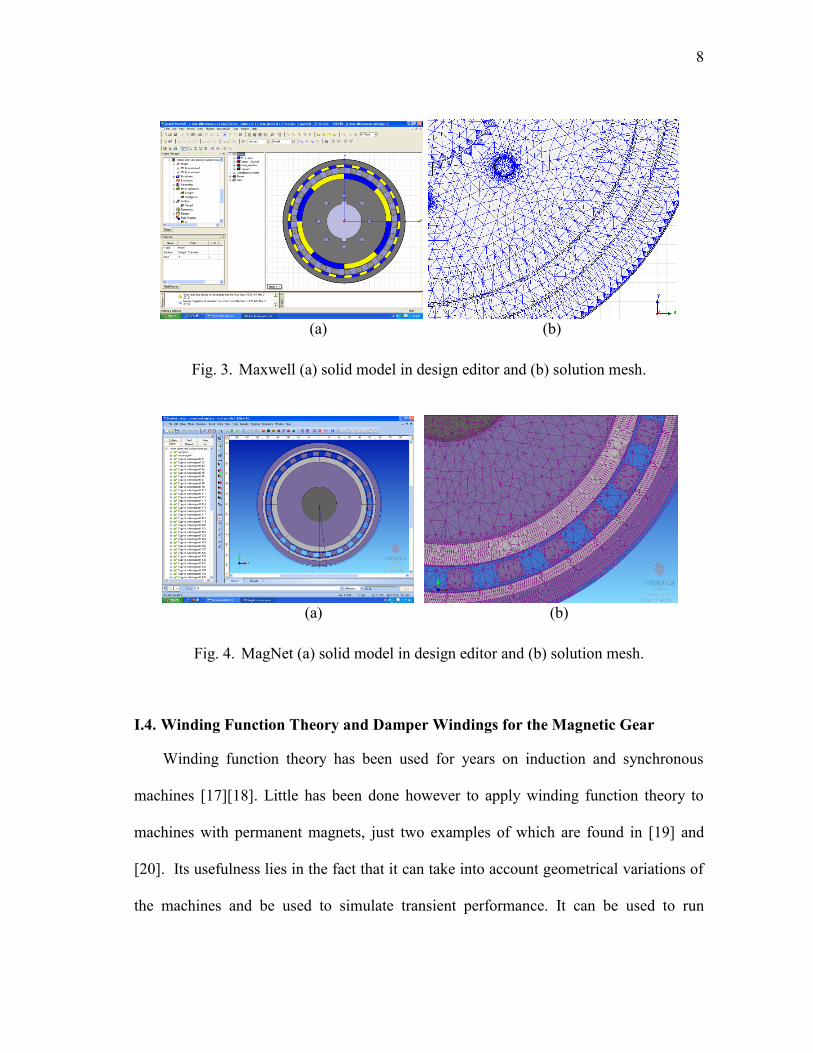
Fig. 3. Maxwell (a) solid model in design editor and (b) solution mesh. ................. 8
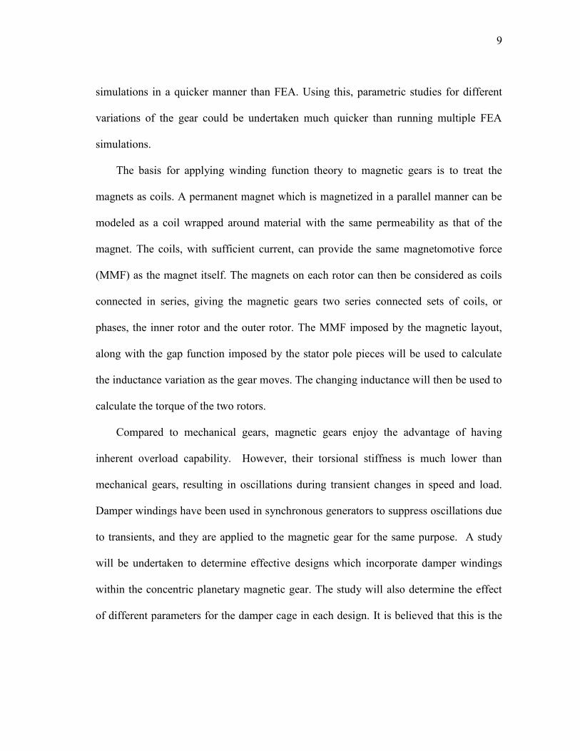
Fig. 4. MagNet (a) solid model in design editor and (b) solution mesh. ................... 8
Fig. 5. The transmotor. ............................................................................................ 17
Fig. 6. HEV drive train with transmotor. ................................................................ 19
Fig. 7. Integrated magnetic gear/PM machine for traction shown (a) inside
wheel and (b) in an assembly of fundamental elements. ............................ 21
Fig. 8. Series HEV drive train with integrated magnetic gear/PM machine
traction units................................................................................................. 22
Fig. 9. HEV drive train with transmotor. ................................................................ 22
Fig. 10. Integrated speed- and torque-coupling drive train with transmotor and
integrated magnetic gear/PM machine. ........................................................ 23
Fig. 11. Magnetic gear with 31 outer and 5 inner pole pairs..................................... 25
Fig. 12. The modulation of the radial flux density due to the pole pieces in a
gear with 4 inner and 22 outer pole pairs. .................................................... 26
Fig. 13. Assembly showing (a) outer magnetic ring fixed, (b) stator segments
fixed, and (c) inner magnetic ring fixed....................................................... 27
Fig. 14. Torque curves revealing equilibrium points for the 22/4 magnetic gear. .... 29
Fig. 15. Torque transfer showing ripple with change in speed. ................................ 32
Fig. 16. Percentage torque ripple for high-speed and low-speed rotors for whole
gear ratios. .................................................................................................... 33
Fig. 17. Percentage torque ripple for high-speed and low-speed rotors for half
and third gear ratios. .................................................................................... 33
xi
Fig. 18. Percentage torque ripple for high-speed and low-speed rotors for
remaining fractional gear ratios. .................................................................. 34
Fig. 19. Torque transfer in 28/4 gear for (a) fixed stator and (b) fixed outer rotor
operation. ..................................................................................................... 36
Fig. 20. Flux plot showing leakage flux paths (circled in blue) between adjacent
magnets of inner rotor. ................................................................................. 37
Fig. 21. 31/4 magnetic gear using (a) saliency for flux barriers and (b)
integrated flux barriers. ................................................................................ 39
Fig. 22. 31/4 magnetic gear using (a) saliency for flux barriers and (b)
integrated flux barriers. ................................................................................ 40
Fig. 23. An idealized construction of the concentric planetary magnetic gear
used to develop winding function theory for the gear. ................................ 43
Fig. 24. An idealized machine with conductors in the air gap. ................................. 44
Fig. 25. An idealized machine with multiple coils in the air gap. ............................. 47
Fig. 26. An idealized machine with a salient rotor and conductors in the air gap. ... 49
Fig. 27. Model of a permanent magnet with coils fed by DC current which
produces an equivalent magnetization vector. ............................................. 52
Fig. 28. Permanent magnets with alternating vectors form the basis for a single
turns function over the circumference of the rotor. ..................................... 53
Fig. 29. An 8-pole rotor with infinitesimally narrow coil sides and its resulting
turns function. .............................................................................................. 53
Fig. 30. The turns function modeled with the Fourier Series. ................................... 54
Fig. 31. An ideal four pole machine. ......................................................................... 54
Fig. 32. Turns and winding functions for stator phases. ........................................... 55
Fig. 33. Idealized machines built in MagNet showing combinations among 2
and 4 pole stator windings and 2 and 4 pole synchronous rotors, (a)
machine 1, (b) machine 2, (c) machine 3, and (d) machine 4. ..................... 57
Fig. 34. Inductances calculated with FEA for (a) machine 1, (b) machine 2, (c)
machine 3, and (d) machine 4. ..................................................................... 58
Page
xii
Fig. 35. Flowchart for calculated inductances using MWFT in Matlab/Simulink. ... 59
Fig. 36. Inverse gap function used for ideal machines in inductance
calculations. ................................................................................................. 59
Fig. 37. Inductances calculated with MWFT for (a) machine 1, (b) machine 2,
(c) machine 3, and (d) machine 4................................................................. 60
Fig. 38. 8-pole radial magnetic coupling with (a) permanent magnets and (b)
coils. ............................................................................................................. 61
Fig. 39. Mutual inductance of inner rotor calculated with FEA and MWFT. ........... 62
Fig. 40. Linear sections of magnetizing inductance calculations for (a) inner
rotor and (b) outer rotor. .............................................................................. 63
Fig. 41. Magnetizing inductances calculated with FEA for (a) inner rotor and
(b) outer rotor. .............................................................................................. 64
Fig. 42. Magnetizing inductances calculated with MWFT for (a) inner rotor and
(b) outer rotor. .............................................................................................. 64
Fig. 43. Difference in flux paths with MWFT and FEA. .......................................... 65
Fig. 44. Inverse gap function used for mutual inductance calculations. ................... 66
Fig. 45. Mutual inductances calculated by MWFT and FEA for (a) the inner
rotor and (b) the outer rotor. ........................................................................ 66
Fig. 46. Validity of replacing magnets with coils shown over a pole pair pitch
showing torque curves for the (a) outer rotor and (b) inner rotor. ............... 68
Fig. 47. Changing reluctance as magnets move over pole pieces. ............................ 68
Fig. 48. Torque of inner rotor of magnetic coupling calculated with FEA and
MWFT.......................................................................................................... 70
Fig. 49. Torques calculated with MWFT for (a) inner rotor cogging torque, (b)
outer rotor cogging torque, (c) inner rotor stall torque, and (d) outer
rotor stall torque. .......................................................................................... 71
Fig. 50. Base designs with damper windings included for (a) salient pole design,
(b) spoke design, (c) IPM design with damper bars in the flux barriers,
and (d) IPM design with damper bars behind the magnets. ......................... 74
Page
xiii
Fig. 51. Value of spring constant K shown linearized about the origin for the
salient pole design. ....................................................................................... 75
Fig. 52. Comparison of settling times between (a) salient pole design and (b)
salient pole design with damper windings. .................................................. 77
Fig. 53. Bar arrangement for 4 bars in one pole of the magnetic gear. ..................... 80
Fig. 54. Flux linkage in the salient pole design with 4 bars per pole as it settles
to equilibrium. .............................................................................................. 80
Fig. 55. Effect of damper bar radius on settling time. ............................................... 82
Fig. 56. Effect of end ring resistance on settling time............................................... 83
Fig. 57. Effect of end ring inductance on settling time. ............................................ 84
Fig. 58. Final design for the concentric planetary magnetic gear with damper
windings. ...................................................................................................... 85
Fig. 59. Stall torque rating of the outer rotor as the inner rotor magnets are
shifted towards the shaft. ............................................................................. 86
Fig. 60. Transient performance of the final design. .................................................. 87
Fig. 61. Current in a damper bar at steady state. ....................................................... 87
Fig. 62. New variations of the stator with arrows pointing to bridges connecting
the stator pieces on the (a) interior, (b) exterior, and (c) both sides. ........... 91
Fig. 63. Prototype (a) FEA model and (b) FEA-calculated torque angle curve. ....... 92
Fig. 64. Stall torque raring with respect to bridge thickness for (a) inner
connection and (b) outer connection. ........................................................... 94
Fig. 65. Torques calculated using coils and permanent magnets with FEA for
(a) outer rotor and (b) inner rotor. ................................................................ 95
Fig. 66. Magnetizing inductances calculated with FEA for (a) inner rotor, and
(b) outer rotor. .............................................................................................. 96
Fig. 67. Mutual inductances calculated with FEA for (a) inner rotor and (b)
outer rotor..................................................................................................... 96
Fig. 68. Additional flux leakage paths shown circled in the calculation of Lio. ........ 97
Page
xiv
Fig. 69. Turns function for inner rotor. ..................................................................... 98
Fig. 70. Magnetizing inductances calculated with MWFT for (a) inner rotor and
(b) outer rotor. .............................................................................................. 99
Fig. 71. Mutual inductances calculated with MWFT for (a) inner rotor and (b)
outer rotor..................................................................................................... 99
Fig. 72. Flux aided by the addition of stator bridges shown circled. ...................... 101
Fig. 73. Magnetizing inductances for stator segments connected with bridges
calculated with FEA for (a) inner rotor and (b) outer rotor. ...................... 102
Fig. 74. Mutual inductances for stator segments connected with bridges
calculated with FEA for (a) inner rotor and (b) outer rotor. ...................... 102
Fig. 75. Torques calculated with MWFT accounting for IPM geometry for (a)
inner rotor cogging torque, (b) outer rotor cogging torque, (c) inner
rotor stall torque, and (d) outer rotor stall torque....................................... 103
Fig. 76. Steady state torque ripple calculated with FEA for the (a) inner rotor
and (b) outer rotor. ..................................................................................... 104
Fig. 77. New inner rotor and stator redesign with (a) laminations shown and (b)
assembled with magnets. ........................................................................... 105
Fig. 78. Assembly of stator with (a) sectioned view of mold and (b) stack with
aluminum rods to adhere stack to base. ..................................................... 105
Fig. 79. Assembly of the inner rotor (a) before magnets shown in front of outer
rotor assembly and (b) during placement of magnet pairs. ........................ 106
Fig. 80. Second (left) and third (right) iteration of the stator stack. ........................ 107
Fig. 81. Magnets on the outer rotor with lost coatings due to contact with stator
stack. .......................................................................................................... 108
Fig. 82. Verification of stator stack concentricity by using the lathe...................... 108
Fig. 83. Dynamometer for testing the magnetic gear prototype. ............................. 109
Fig. 84. Steady-state torque ripple of the gearbox under no load. .......................... 110
Fig. 85. Torque waveforms of both rotors when inner rotor experiences a stall. ... 111
Fig. 86. Replacement of bearings from (a) angular contact to (b) tapered roller. ... 112
Page

xv
Fig. 87. New prototype with rotors supported from both sides. .............................. 112
Fig. 88. 3D model of the magnetic gear simulated in MagNet‟s 3D static solver
showing solutions for the (a) shaded flux density field and the (b)
vector field of flux density. ........................................................................ 116
Page
xvi
LIST OF TABLES
Page
Table I. Gear ratios for chosen pole pair ratio models .............................................. 30
Table II. Dimensions for models in preliminary gearing ratio analysis ..................... 31
Table III. Torque ripple results between operating modes .......................................... 34
Table IV. Comparison of performance for 31/4 models .............................................. 39
Table V. Parameters for ideal machine simulations ................................................... 57
Table VI. Parameters for 8-pole coupling .................................................................... 61
Table VII. Parameters common to all designs ............................................................... 73
Table VIII. Settling times for base designs and base designs with damper windings .... 76
Table IX. Cost for magnetic gear prototype ................................................................. 90
Table X. Magnetic gear dimensions ........................................................................... 90
Table XI. Stall torque rating for different FEA packages and variations of the
stator ............................................................................................................. 93

1
* I. INTRODUCTION
Electromechanical systems in many industrial areas strive for greater torque density
to reduce volume and weight. One of the traditional ways of increasing torque density
with regards to an electric motor is to couple it to a gear. Few institutions however have
done work in the area of magnetic gears in order to bring the technology to maturity.
A study of the concentric planetary gear will be taken which looks at strengthening
the stator pole pieces. This is of key importance towards industrial use, since the stator
pole pieces must withstand the sum of the torques for both magnetic rotors. In addition,
the use of an interior permanent magnetic configuration is studied and built in a
prototype. Finite element analysis is used to study the effect of stall torque rating
between the different configurations.
Winding function theory, which has been used to study induction and synchronous
machines, will be applied to the magnetic gear. Thus far, analysis of magnetic gears has
been restricted to two main methods for torque calculation: Finite Element Analysis
(FEA) which most commonly uses either the coenergy or Maxwell stress tensor
methods, and numerical analysis using the Maxwell stress tensor method with Fourier
_____________
This dissertation follows the style and format of the IEEE Transactions on Magnetics.
* © 2010 IEEE. Reprinted with permission from "Analysis of the concentric planetary
magnetic gear with strengthened stator and interior permanent magnet (IPM) inner
rotor" by N.W. Frank and H.A. Toliyat, in Proc. IEEE Energy Convers. Cong. Exp.
ECCE 2010, pp. 2977-2984. For more information go to http://thesis.tamu.edu
/forms/IEEE%20permission%20note.pdf/view.

2
series for the magnetic fields. While both methods are rigorous and yield good results for
2D simulations, they can be lengthy to setup and run. The winding function method
allows quicker setup and analysis of gear variations than with FEA, and it can also yield
stall torque as well as cogging torque waveforms. The analysis is the first of its kind to
apply a theory which has historically been applied to electric machines with windings,
and rarely with electric machines containing magnets, to a device devoid of windings
altogether.
In addition, the application of damper windings to the magnetic gear will also be
investigated. Magnetic gears offer the distinct advantage of overload protection, at the
cost of torsional stiffness with respect to mechanical gears. Designs with damper
windings will be evaluated for their effectiveness in suppressing transient oscillations
due to changes in speed and load. It is believed that this is the first means of passively
suppressing oscillations, whereas other means have been active.
I.1. History of Magnetic Gears
The idea behind a gear using permanent magnets dates back as early as the 1940‟s
with a US patent by Faus [1]. A handful of patents over the years have followed, most of
them occurring within the past few decades. A summary of patents related to magnetic
gearing can be found in Appendix A. Early magnetic gears using ferrite magnets and
spur gear configurations yielded poor torque densities. With the advent of rare-earth
permanent magnets, more work has been done at achieving greater torque density out of
magnetic gears. Early work was done by Tsurumoto [2] with non-concentric magnetic

3
gears using Samarium Cobalt magnets. More research and prototypes followed with the
concentric planetary magnetic gear in [3],[4], and [5].
Since then, more work has been done on new designs which yield greater gearing
ratios or control. In [6], windings were placed on the outside of the concentric planetary
magnetic gear to help dampen the gearbox against transient responses. In [7], the
concentric planetary gear was proposed for use with counter-rotating tidal turbines, and a
prototype was built. In [8], the concentric planetary magnetic gear was redesigned with
Halbach arrays for the magnetic rotors in comparison to parallel-magnetized magnets.
The results showed a higher stall torque rating, as well as lower torque ripple and iron
losses. In [9], a concentric planetary magnetic gear was built which used an axial flux
configuration for the stator pole pieces, instead of a radial flux configuration.
Other designs have also begun to appear to achieve higher torque density ratings. In
[10], a planetary gearing arrangement using a sun gear and planet gears was simulated
and fabricated, which yielded a torque density close to 100 kNm/m3. In [11], a cycloid
magnetic gear was analyzed and fabricated. The cycloid gear utilizes a cycloid action to
modulate the air gap between the two magnetic rings, thus achieving a high gear ratio
and torque density, at the cost of a very complex bearing layout. In [12] the harmonic
magnetic gear was studied and built. In this design, instead of using a cycloid action to
modulate the air gap between the magnetic rings, a flexible rotor was proposed, in which
the inner rotor would change shape and thus the air gap.
4
I.2. Elements of Comparison from Mechanical Gears
Mechanical gears are found in the writings of Aristotle as early as 330 B.C., and
even a chariot used by China‟s Yellow Emperor for navigation over 4500 years ago. The
earliest gears were made of wood, and crafted individually by hand without much regard
to mechanical engineering theory. Around 1500, Juanelo Torriano of Spain fashioned the
first known gear cutting machine. Greater interest in the engineering theory behind gears
followed. Around 1800, metal gears moved from the arena of clocks to larger power
drives [13].
If magnetic gears are intended to replace mechanical gears in numerous
applications, then parameters must be studied for means of comparison. In general, the
layout of magnetic gears borrows directly from layouts intended for mechanical gears.
I.2.1. Spur gears
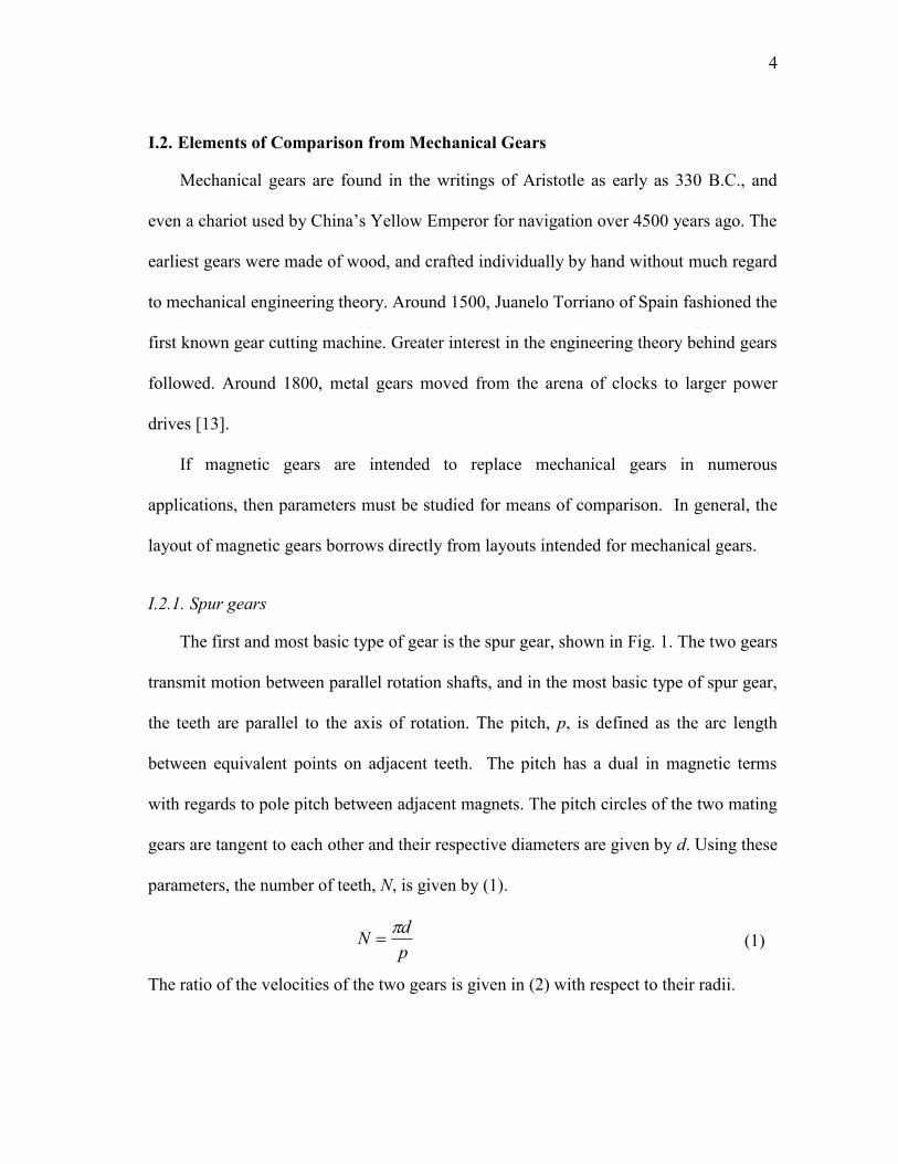
The first and most basic type of gear is the spur gear, shown in Fig. 1. The two gears
transmit motion between parallel rotation shafts, and in the most basic type of spur gear,
the teeth are parallel to the axis of rotation. The pitch, p, is defined as the arc length
between equivalent points on adjacent teeth. The pitch has a dual in magnetic terms
with regards to pole pitch between adjacent magnets. The pitch circles of the two mating
gears are tangent to each other and their respective diameters are given by d. Using these
parameters, the number of teeth, N, is given by (1).
p
dN
(1)
The ratio of the velocities of the two gears is given in (2) with respect to their radii.

5
(a) (b)
Fig. 1. Spur gear with (a) equal radii and (b) with parameter circles.
1
2
2
1
r
r
(2)
The additional circles in Fig. 1b outline parameters of the teeth in the gears. The
addendum circle outlines the top land, or outermost portion of the teeth, while the
dedendum circle outlines the bottom land, or lowermost portion of the teeth. Spur gears,
and gears in general, use the involute profile to form the teeth. The involute which forms
the teeth is formed on the base circles of the respective gears [14].
I.2.2. Planetary gears
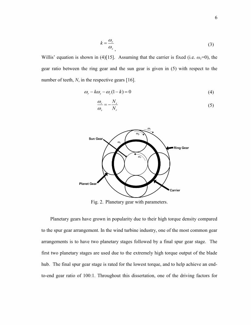
A newer and very popular type of gearing arrangement is the planetary arrangement
shown in Fig. 2. The multiple gears are arranged around the central sun gear. Around
the sun gear are planet gears which rotate about the central axis, as well as their
individual axes. The planet gears are connected via a common carrier which can rotate
about the central axis. Surrounding all of these is the ring gear.
The gear ratio is found by applying Willis‟ equation to the gear. In 1841, Willis
showed that the motion could be explained by a superposition of partial motions. Using
the ratio of the speed of the ring and sun gears relative to the carrier:
6
s
rk
, (3)
Willis‟ equation is shown in (4)[15]. Assuming that the carrier is fixed (i.e. ωc=0), the
gear ratio between the ring gear and the sun gear is given in (5) with respect to the
number of teeth, N, in the respective gears [16].
0)1( kk csr (4)
r
s
s
r
N
N
(5)
Fig. 2. Planetary gear with parameters.
Planetary gears have grown in popularity due to their high torque density compared
to the spur gear arrangement. In the wind turbine industry, one of the most common gear
arrangements is to have two planetary stages followed by a final spur gear stage. The
first two planetary stages are used due to the extremely high torque output of the blade
hub. The final spur gear stage is rated for the lowest torque, and to help achieve an end-
to-end gear ratio of 100:1. Throughout this dissertation, one of the driving factors for
7
improvement of the gear is to increase torque density. With an increase in torque
density, the gear becomes more attractive for industrial use.
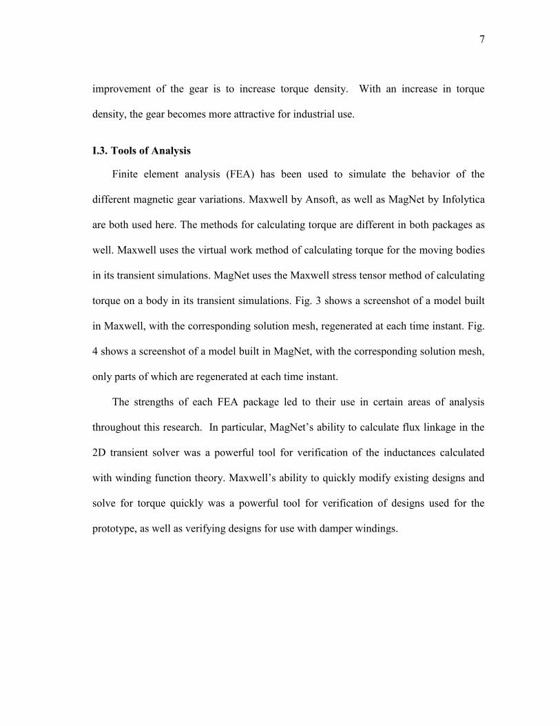
I.3. Tools of Analysis
Finite element analysis (FEA) has been used to simulate the behavior of the
different magnetic gear variations. Maxwell by Ansoft, as well as MagNet by Infolytica
are both used here. The methods for calculating torque are different in both packages as
well. Maxwell uses the virtual work method of calculating torque for the moving bodies
in its transient simulations. MagNet uses the Maxwell stress tensor method of calculating
torque on a body in its transient simulations. Fig. 3 shows a screenshot of a model built
in Maxwell, with the corresponding solution mesh, regenerated at each time instant. Fig.
4 shows a screenshot of a model built in MagNet, with the corresponding solution mesh,
only parts of which are regenerated at each time instant.
The strengths of each FEA package led to their use in certain areas of analysis
throughout this research. In particular, MagNet‟s ability to calculate flux linkage in the
2D transient solver was a powerful tool for verification of the inductances calculated
with winding function theory. Maxwell‟s ability to quickly modify existing designs and
solve for torque quickly was a powerful tool for verification of designs used for the
prototype, as well as verifying designs for use with damper windings.
8
(a) (b)
Fig. 3. Maxwell (a) solid model in design editor and (b) solution mesh.
(a) (b)
Fig. 4. MagNet (a) solid model in design editor and (b) solution mesh.
I.4. Winding Function Theory and Damper Windings for the Magnetic Gear
Winding function theory has been used for years on induction and synchronous
machines [17][18]. Little has been done however to apply winding function theory to
machines with permanent magnets, just two examples of which are found in [19] and
[20]. Its usefulness lies in the fact that it can take into account geometrical variations of
the machines and be used to simulate transient performance. It can be used to run
9
simulations in a quicker manner than FEA. Using this, parametric studies for different
variations of the gear could be undertaken much quicker than running multiple FEA
simulations.
The basis for applying winding function theory to magnetic gears is to treat the
magnets as coils. A permanent magnet which is magnetized in a parallel manner can be
modeled as a coil wrapped around material with the same permeability as that of the
magnet. The coils, with sufficient current, can provide the same magnetomotive force
(MMF) as the magnet itself. The magnets on each rotor can then be considered as coils
connected in series, giving the magnetic gears two series connected sets of coils, or
phases, the inner rotor and the outer rotor. The MMF imposed by the magnetic layout,
along with the gap function imposed by the stator pole pieces will be used to calculate
the inductance variation as the gear moves. The changing inductance will then be used to
calculate the torque of the two rotors.
Compared to mechanical gears, magnetic gears enjoy the advantage of having
inherent overload capability. However, their torsional stiffness is much lower than
mechanical gears, resulting in oscillations during transient changes in speed and load.
Damper windings have been used in synchronous generators to suppress oscillations due
to transients, and they are applied to the magnetic gear for the same purpose. A study
will be undertaken to determine effective designs which incorporate damper windings
within the concentric planetary magnetic gear. The study will also determine the effect
of different parameters for the damper cage in each design. It is believed that this is the
10
first attempt to add a passive means of oscillation damping to the magnetic gear, whereas
all other previous means have been active.
I.5. The Prototype
The analysis undertaken is supported by the fabrication of a prototype. The original
prototype, begun in [5], was borrowed from the Institute of Energy Technology at
Aalborg University in Denmark. The stator and rotor have been reconstructed to verify
the new variations. Problems associated with their construction are discussed to help
with prototypes in the future, and a layout for an improved prototype is given.
A dynamometer has been setup with torque transducers to monitor the torque
waveform of both rotors of the gear. The outer rotor is driven by an induction
servomotor and the inner rotor is loaded with a hysteresis brake. Results will be shown
which are in agreement with the stall torque rating found with other prototypes.

11
* II. MAGNETIC GEARS
II.1. Applications
The applications for magnetic gears are as numerous as the applications for
traditional mechanical gears. In the case of the gear studied here, it can be suited to three
very large industries: wind turbines, ship propulsion, and vehicle traction.
II.1.1. Wind turbines
Sustainable energy accounted for 23% (31 GW) of added power generation capacity
worldwide in 2007. The majority of new investments into sustainable energy were
dominated by wind, totaling 43% [21]. In 2008, wind energy totaled 45% of all
investments worldwide for sustainable energy. As of 2009, wind had climbed to 56% of
all financial investments worldwide for sustainable energy [22]. There is a need for
improvement in turbine design to not only increase the standard generation capacity of a
single turbine, but also reduce maintenance needs for the plethora of turbines located on
wind farms throughout the world.
Of primary importance is the migration from purely mechanical components to
electromechanical ones. The majority of turbines incorporate a mechanical gearbox in
line with the generator to take the high-torque, low-speed output from the hub and
_____________
* © 2009 IEEE. Reprinted with permission from "Gearing ratios of a magnetic gear for
marine applications" by N.W. Frank and H.A. Toliyat, in Proc. IEEE Symp. ESTS 2009,
pp. 477-481, and from "Gearing ratios of a magnetic gear for wind turbines" by N.W.
Frank and H.A. Toliyat, in Proc. IEEE Int. Conf. IEMDC 2009, pp. 1224-1230. For
more information go to http://thesis.tamu.edu/forms/IEEE%20permission%20note
.pdf/view.
12
transfer it into a high-speed, low-torque input to the generator. A small but growing
segment of the wind turbine industry has resorted to directly driving the generator from
the blade hub. This necessitates a generator which is relatively enormous compared to
generators in other wind turbines.
Moving to a directly-driven system is approaching size and weight issues however.
Compared to their counterparts, directly-driven wind turbines suffer from heavier tower
head weights due to the large generators. In the biggest versions supplied by Enercon,
the generators are approaching technical as well as economically feasible limits for
lifting them high into the air for assembly [23][24].
The gearbox of a wind turbine is placed in a unique situation, one in which the load
is stochastically varying and only partial. A failure of this component can cripple a
turbine for long periods of time. In the early years of wind turbines, during the WEGA
(from the German „Wind Energie Große Anlagen‟) program in Europe, a gearbox failure
crippled the Tjaereborg turbine in Denmark for 16 months [25]. Indeed one of the largest
sources of unplanned maintenance in offshore wind farms in the United Kingdom was
the gearbox itself or the gearbox bearings [26]-[29]. Many times this necessitated a
replacement of the entire gearbox. Noise complaints are also becoming more common as
turbines are placed in urban areas. According to [25], in many cases where complaints
about noise were raised from nearby residents, the gearbox was found to be the source.
The gearbox collectively refers to the gears composing different stages housed
inside a casing with bearings. This component has been a great concern of the wind
industry since its advent in the 1980‟s. At the time, specialized gearing stages had not

13
been engineered for wind turbines and thus regular industrial gears were used on these
early turbines. Shortly thereafter, it became apparent that these regular gearboxes were
ill-suited for the application, and gearbox manufacturers began designing units
specifically for their wind turbine customers. Once turbines of 500 kW reached
production in the 1990‟s, gearbox manufacturers began designing planetary stages for
added torque density. As wind turbines have continued to grow in size and torque output
from the hub, gearbox manufacturers have struggled to keep up with the higher ratings,
as well as the demanding requirements of a wind turbine. Gear manufacturers readily
admit that wind turbines are the most demanding application which they supply, one in
which the loads are variable and arduous to predict [30].
Due to the demanding requirements and technical ability required to design a good
gearbox, the field of suppliers for wind turbine manufacturers is greatly narrowed
compared to other applications. As of 2005, only two gearbox manufacturers supplied
roughly 80% of the wind turbine market, Winergy of Germany and Hansen of Belgium.
This forces some wind turbine manufacturers to purchase gearboxes from companies
which are owned by rival wind turbine manufacturers. Winergy, owned by Siemens, also
supplies Vestas and GE among others. This also limits the variety of gearboxes that a
wind turbine manufacturer can spread across its production line. In order to hedge
against a single gearbox having a failure across a fleet of turbines, as well as supply-
chain interruptions, gearboxes from multiple suppliers will be used in a fleet [31]. The
merits of this tactic are best illustrated with the failure of Jahnel-Kestermann gearboxes
14
in NEG Micon turbines in the late 1990‟s. This problem, reported in [32] at the time,
brought NEG Micon to the brink of collapse, right before they were acquired by Vestas.
Some headway has been made into understanding the causes of gearbox failures. It
has been found that bearings are a key instigator in failures, emitting debris which causes
damage to the gear itself. In addition, manufacturers have moved away from spherical
roller bearings to tapered and cylindrical roller bearings to handle higher torque loads. It
is reiterated here that partial loads are a difficult problem for bearings and the gearbox in
general. In order for bearings to reduce their failure rate, load prediction is a key issue
which must be solved. Progress is slow however due to the proprietary nature among
bearing and gearbox manufacturers [33].
Despite the troubles reported by industry, negating the gearbox altogether may not
be the answer. In [34] and [35], variations on wind turbine drive trains were examined
for weight, cost, and efficiency. In [34], a direct-drive solution for a 1.5 MW wind
turbine was roughly 20 tons heavier in the tower head then a fully-geared or single-stage
geared design. In addition, the direct-drive solution was more expensive due to the
higher costs of magnetic steel laminates and copper in the generator.
Later, in [35], a 5 MW design was carried out using only a single-stage gearbox,
termed „multibrid‟ („multi‟ for multi-megawatt and „brid‟ for hybrid). A single-stage
gearbox with a gearing ratio of 1/6.17 was designed in order to increase the generator
speed past 100 rpm. It was found that this design increased reliability by lowering the
rotational speeds which the gearbox has to handle compared to multi-stage high-speed
gearboxes, as well as winding temperatures compared to a large direct-drive generator.
15
It is believed that incorporating a single-stage gearbox in order to increase the
generator speed past 100 rpm will benefit the reliability and performance of the entire
drive train. In addition, the replacement of a conventional gearbox with a magnetic one
will further increase reliability and reduce maintenance.
The advantages of using magnetic gears over traditional gearboxes include inherent
overload protection. Gears which are pushed by torque transients over their torque rating
will slip, instead of possibly breaking teeth. They also provide the advantage of lower
acoustic noise due to the loss of mechanical contact between the teeth. Furthermore, with
the loss of contact between teeth, lubrication is negated and thus maintenance due to oil
changes [5].
II.1.2. Marine propulsion
In an effort to further increase efficiency as well as reliability, marine propulsion
systems are becoming increasingly electromechanical. Electric propulsion has not only
migrated towards technology which increases torque density of the electric machine, but
also technology such as pod propulsion which can provide 360º thrust capability. In
addition, high temperature superconducting (HTS) machines are being studied and built
for their increased torque density. These represent some of the state-of-the-art
technologies which are currently being developed and improved upon for future marine
vessels.
Marine propulsion is an application which demands high torque at low speed. In
electric machines, this tends to require high pole numbers as well as high current.
Electric machines which are rated for megawatts and the speed rating for large marine

16
applications, i.e. no more than roughly 250 rpm, are quite large. In [36], an induction
machine prototype rated for 19 MW and 150 rpm weighed in at a gargantuan 117
Tonnes and occupied over 85 m3. However, induction machine technology, while time-
tested, yields poor torque density among modern electric machines.
Since that prototype, over the last decade, naval machines have been migrating
towards permanent magnets as well as HTS technology to increase torque density.
According to [37], induction machine torque densities are in the range of 3.5 ft-lbs/lb
while advanced permanent magnet and HTS machines are in the range of 16 ft-lbs/lb.
More specifically in [38], modern machine types were compared with the same torque
rating, 2 Mft-lbs. Under the comparison permanent magnet machines were on the high
end with up to 17.2 ft-lbs/lb while HTS machines were on the low end with 14.2 ft-
lbs/lb.
Magnetic gears have been explored more in recent years with the advent of rare-
earth permanent magnets. Gears studied in [4], [5], [11], and [12] range from concentric
planetary gears to newer more exotic versions such as the cycloid and harmonic gear.
The torque densities for the gears studied and built range from 72 Nm/l for early
prototypes all the way to 185 Nm/l for the latest prototypes, compared with 30 Nm/l for
liquid-cooled electric machines.
II.1.3. Hybrid electric vehicles
The application of vehicle traction is also very popular among the power community
and guaranteed to spur further research. The possibilities for drive train layouts are more
numerous than those of wind turbines. Another type of electromagnetic gearing machine,
17
the transmotor, will be examined here for its use in conjunction with the magnetic gear
for vehicle traction.
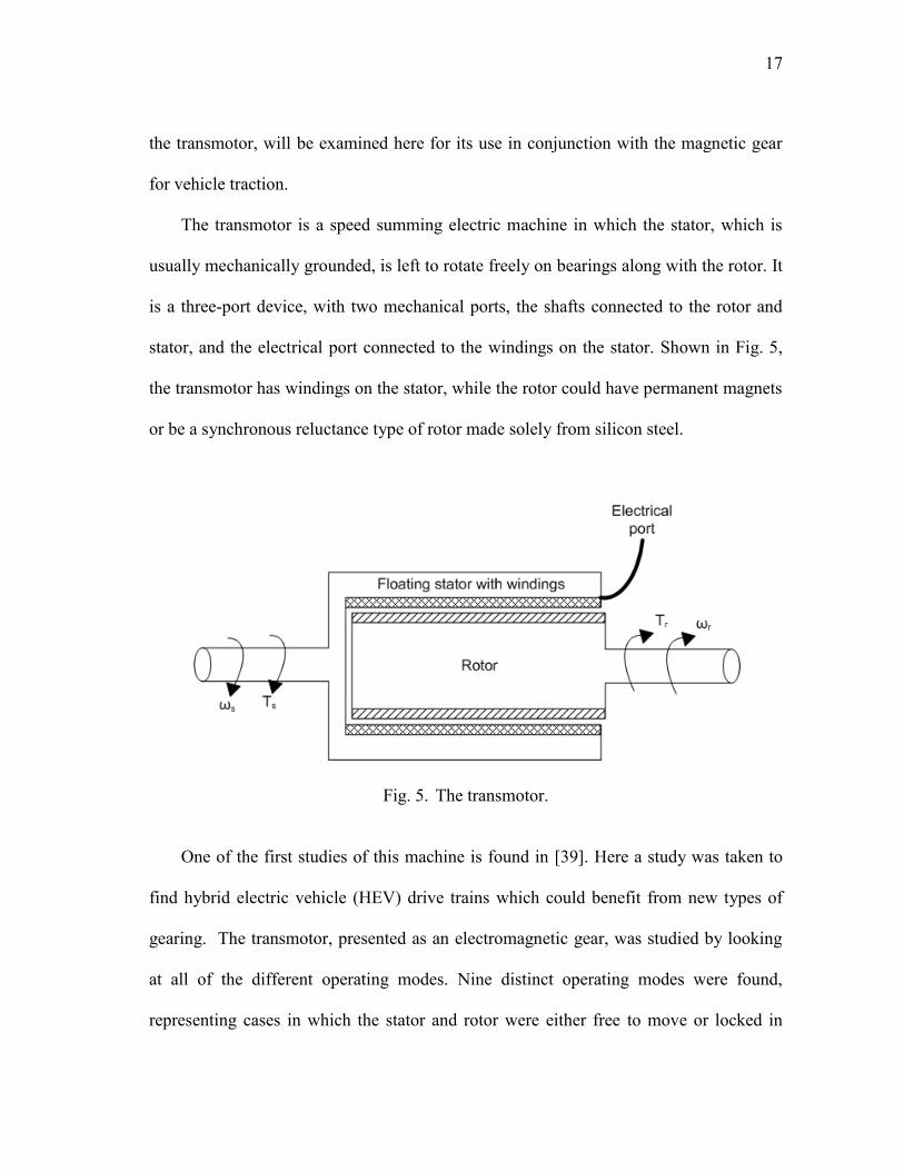
The transmotor is a speed summing electric machine in which the stator, which is
usually mechanically grounded, is left to rotate freely on bearings along with the rotor. It
is a three-port device, with two mechanical ports, the shafts connected to the rotor and
stator, and the electrical port connected to the windings on the stator. Shown in Fig. 5,
the transmotor has windings on the stator, while the rotor could have permanent magnets
or be a synchronous reluctance type of rotor made solely from silicon steel.
Fig. 5. The transmotor.
One of the first studies of this machine is found in [39]. Here a study was taken to
find hybrid electric vehicle (HEV) drive trains which could benefit from new types of
gearing. The transmotor, presented as an electromagnetic gear, was studied by looking
at all of the different operating modes. Nine distinct operating modes were found,
representing cases in which the stator and rotor were either free to move or locked in
18
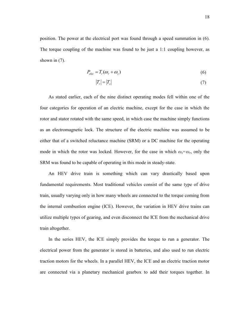
position. The power at the electrical port was found through a speed summation in (6).
The torque coupling of the machine was found to be just a 1:1 coupling however, as
shown in (7).
)( srrelec TP (6)
sr TT (7)
As stated earlier, each of the nine distinct operating modes fell within one of the
four categories for operation of an electric machine, except for the case in which the
rotor and stator rotated with the same speed, in which case the machine simply functions
as an electromagnetic lock. The structure of the electric machine was assumed to be
either that of a switched reluctance machine (SRM) or a DC machine for the operating
mode in which the rotor was locked. However, for the case in which ωs=ωr, only the
SRM was found to be capable of operating in this mode in steady-state.
An HEV drive train is something which can vary drastically based upon
fundamental requirements. Most traditional vehicles consist of the same type of drive
train, usually varying only in how many wheels are connected to the torque coming from
the internal combustion engine (ICE). However, the variation in HEV drive trains can
utilize multiple types of gearing, and even disconnect the ICE from the mechanical drive
train altogether.
In the series HEV, the ICE simply provides the torque to run a generator. The
electrical power from the generator is stored in batteries, and also used to run electric
traction motors for the wheels. In a parallel HEV, the ICE and an electric traction motor
are connected via a planetary mechanical gearbox to add their torques together. In
19
another type, the series/parallel HEV, the ICE, an electric traction motor, and a generator
are all used in conjunction to either generate electric power or torque for the wheels [40].
The idea behind using an electric machine for vehicle traction dates back to 1900
with [41]. In this example, an electric machine with a floating stator was situated
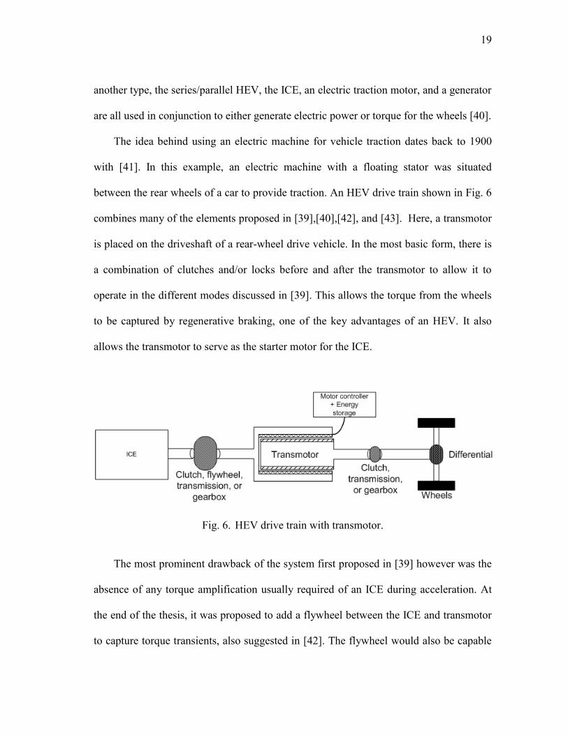
between the rear wheels of a car to provide traction. An HEV drive train shown in Fig. 6
combines many of the elements proposed in [39],[40],[42], and [43]. Here, a transmotor
is placed on the driveshaft of a rear-wheel drive vehicle. In the most basic form, there is
a combination of clutches and/or locks before and after the transmotor to allow it to
operate in the different modes discussed in [39]. This allows the torque from the wheels
to be captured by regenerative braking, one of the key advantages of an HEV. It also
allows the transmotor to serve as the starter motor for the ICE.
Fig. 6. HEV drive train with transmotor.
The most prominent drawback of the system first proposed in [39] however was the
absence of any torque amplification usually required of an ICE during acceleration. At
the end of the thesis, it was proposed to add a flywheel between the ICE and transmotor
to capture torque transients, also suggested in [42]. The flywheel would also be capable
20
of delivering torque when needed, and allow the transmotor to be sized smaller. Another
drawback to the transmotor has due to do with the need for slip rings with a rotating
stator.
More versions in [40] place a transmission in front or behind the transmotor,
referred to as „posttransmission‟ and „pretransmission‟ respectively. When the
transmotor is placed in front of the transmission on the drive train, the ICE and
transmotor have the same speed range, and the electric machine can be sized smaller.
When the transmotor is placed behind the transmission on the drive train, this serves to
optimize the operating points of the ICE, and requires a larger electric machine.
Vehicle traction with the use of magnetic gears is an idea which is relatively new,
and has only recently been presented in the literature [44]-[47]. The idea behind using a
magnetic gear for traction is similar to the system proposed in [41]. The system is
composed of an electromechanical element connected directly to the wheels or via a gear
directly in line with the wheels. In [44],[45], and [47] the magnetic gear is sized to
accommodate a permanent magnet synchronous machine within the interior of the gear
specifically for vehicle traction. Thus, the electromechanical gearbox is a self-contained
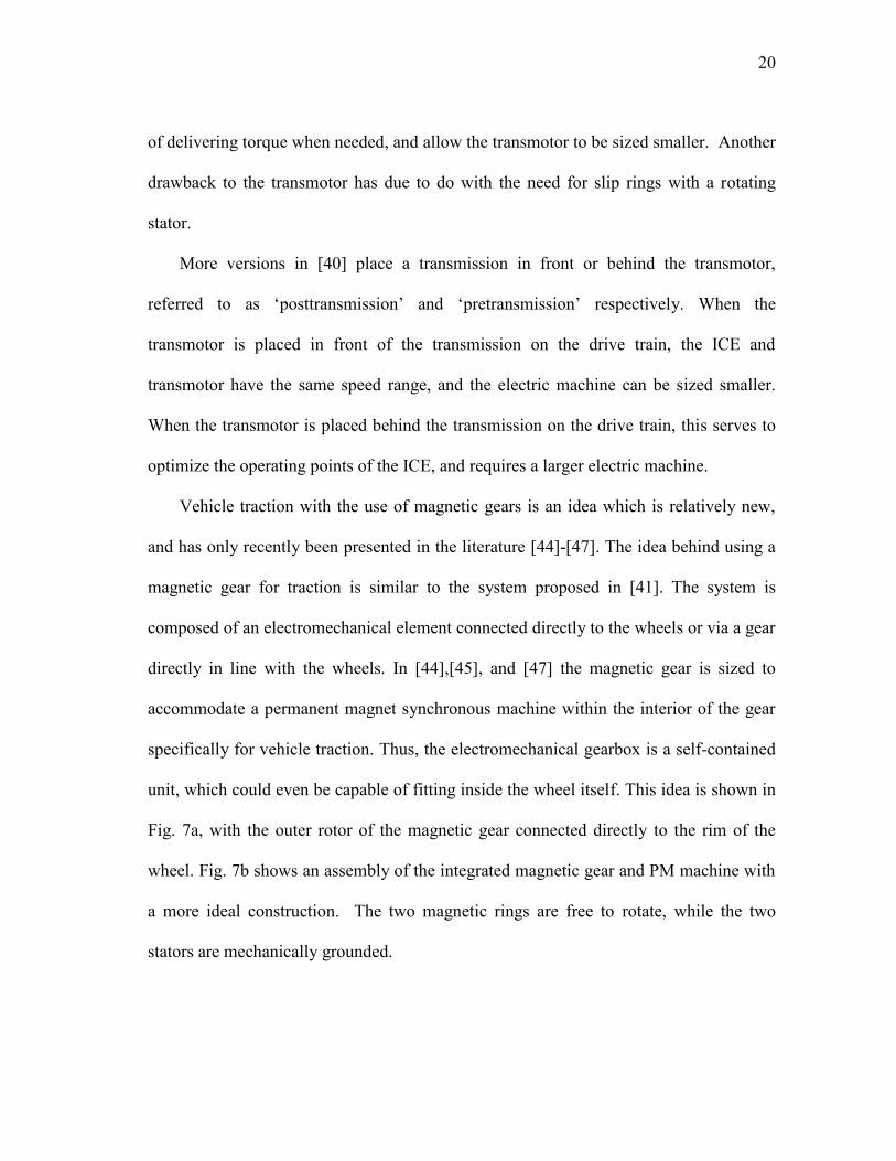
unit, which could even be capable of fitting inside the wheel itself. This idea is shown in
Fig. 7a, with the outer rotor of the magnetic gear connected directly to the rim of the
wheel. Fig. 7b shows an assembly of the integrated magnetic gear and PM machine with
a more ideal construction. The two magnetic rings are free to rotate, while the two
stators are mechanically grounded.
21
(a) (b)
Fig. 7. Integrated magnetic gear/PM machine for traction shown (a) inside wheel and
(b) in an assembly of fundamental elements.
Like the transmotor, this integrated magnetic gear/PM machine is a three-port
device, with two mechanical ports consisting of the rotors, and the electrical port of the
permanent magnet synchronous machine. This unit has the advantage of keeping the
stators mechanically grounded, and thus slip rings are not needed, which can
significantly increase the volume needed for the machine. This type of unit lends itself
easily to the series HEV drive train shown in Fig. 8. The key advantage to this
arrangement over previously constructed series HEV drive trains is that the size of the
electric traction motor is reduced due to the magnetic gear. In [47], the integrated unit
has a calculated torque density of 130 Nm/l. A unit could be placed on multiple wheels
and provide independent torque and speed control of their respective wheels.
22
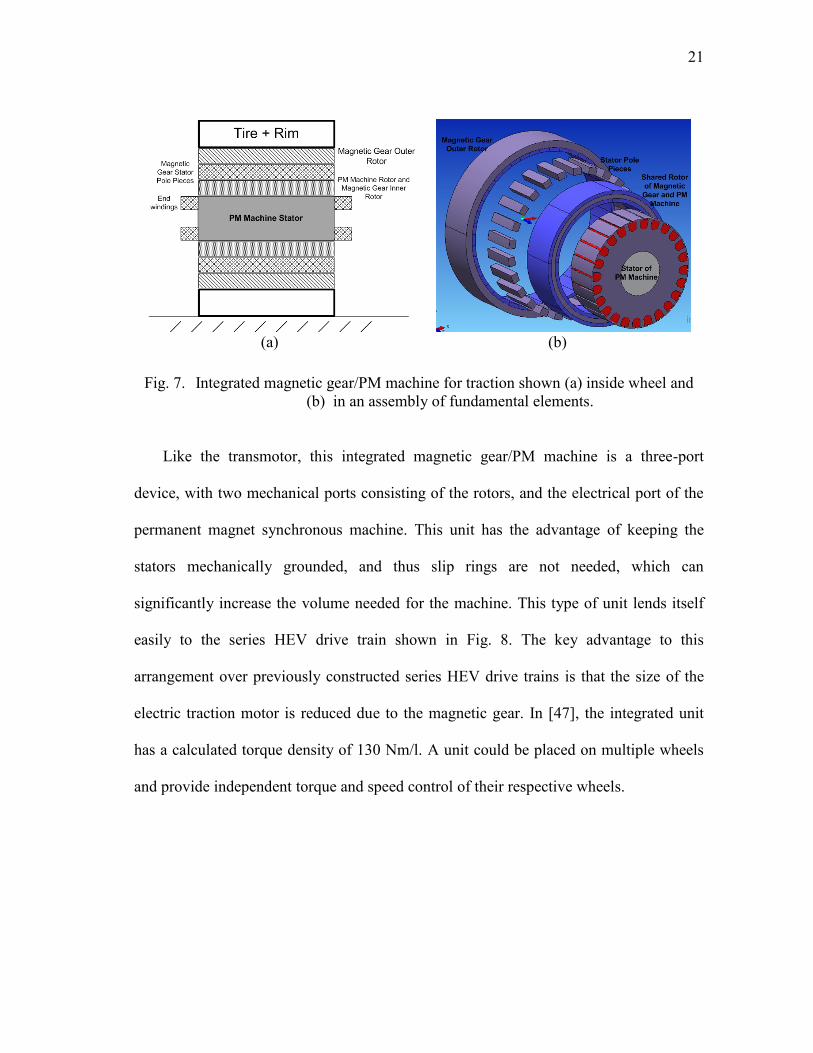
Fig. 8. Series HEV drive train with integrated magnetic gear/PM machine traction units.
The drive train shown in Fig. 8 suffers from the fact that it requires three electric
machines, two in the integrated traction units, and one for electric power generation from
the ICE. The added complexity for control of three electric machines is also a drawback.
Looking again at the drive train with the transmotor in Fig. 6, one of the key drawbacks
was the need for torque amplification from the ICE during acceleration. With the torque
amplification of a gear, the ICE can be sized smaller. This drive train could be helped
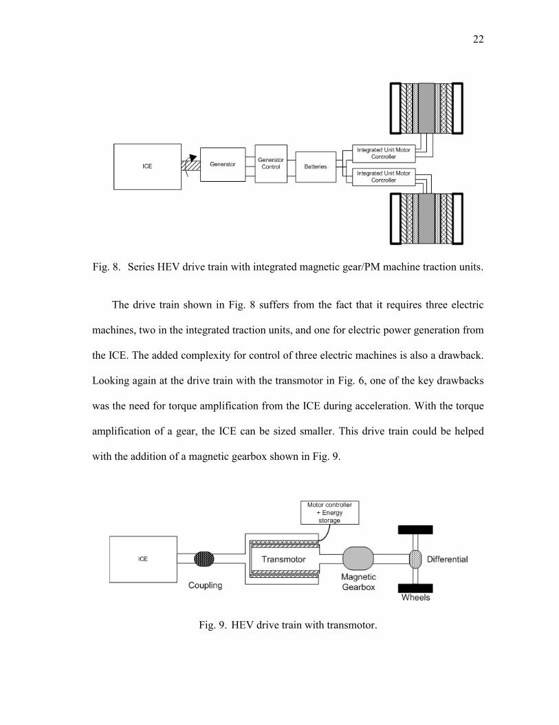
with the addition of a magnetic gearbox shown in Fig. 9.
Fig. 9. HEV drive train with transmotor.

23
The drive train in Fig. 9 has the advantage of needing control of only one electric
machine. It has the ability to capture energy from regenerative braking, and the ICE is
reduced in size due to the magnetic gearbox. The magnetic gear is a passive element and
does not need its own controller.
A more complex HEV drive train is employed in the Toyota Prius and Camry,
referred to as an integrated speed- and torque-coupling drive train. A transmotor drive
train is proposed in [40] which retains the same advantages of the Toyota Prius and
Camry, while still requiring an electric traction motor. This drive train has the
advantages of being able to use an electric machine for regenerative braking, while also
being able to employ both the ICE and the electric traction motor for torque. However,
the drive train proposed can still be improved with the replacement of the electric
traction motor by the integrated magnetic gear/PM machine. The increased torque
density over a traditional liquid-cooled machine would require the use of a smaller
overall system for traction, shown in Fig. 10.
Fig. 10. Integrated speed- and torque-coupling drive train with transmotor and
integrated magnetic gear/PM machine.
24
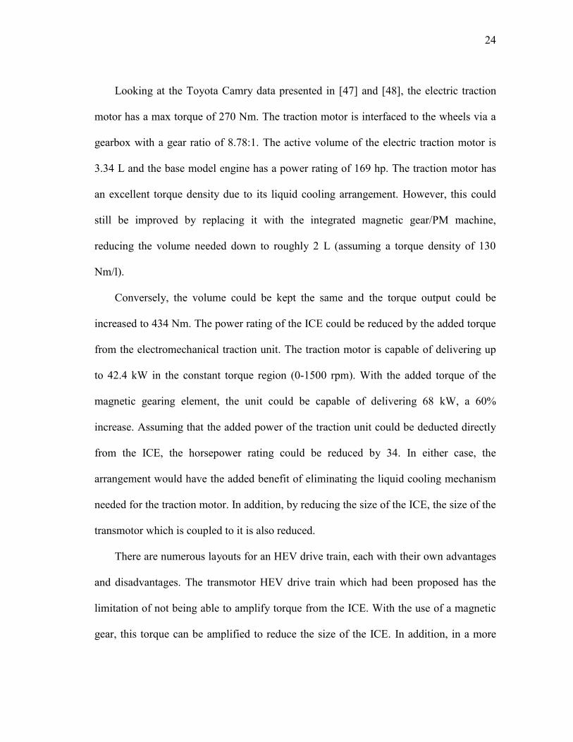
Looking at the Toyota Camry data presented in [47] and [48], the electric traction
motor has a max torque of 270 Nm. The traction motor is interfaced to the wheels via a
gearbox with a gear ratio of 8.78:1. The active volume of the electric traction motor is
3.34 L and the base model engine has a power rating of 169 hp. The traction motor has
an excellent torque density due to its liquid cooling arrangement. However, this could
still be improved by replacing it with the integrated magnetic gear/PM machine,
reducing the volume needed down to roughly 2 L (assuming a torque density of 130
Nm/l).
Conversely, the volume could be kept the same and the torque output could be
increased to 434 Nm. The power rating of the ICE could be reduced by the added torque
from the electromechanical traction unit. The traction motor is capable of delivering up
to 42.4 kW in the constant torque region (0-1500 rpm). With the added torque of the
magnetic gearing element, the unit could be capable of delivering 68 kW, a 60%
increase. Assuming that the added power of the traction unit could be deducted directly
from the ICE, the horsepower rating could be reduced by 34. In either case, the
arrangement would have the added benefit of eliminating the liquid cooling mechanism
needed for the traction motor. In addition, by reducing the size of the ICE, the size of the
transmotor which is coupled to it is also reduced.
There are numerous layouts for an HEV drive train, each with their own advantages
and disadvantages. The transmotor HEV drive train which had been proposed has the
limitation of not being able to amplify torque from the ICE. With the use of a magnetic
gear, this torque can be amplified to reduce the size of the ICE. In addition, in a more
25
complex arrangement, a transmotor can be used with an integrated magnetic gear/PM
machine to provide an integrated speed- and torque-coupling drive train similar to the
Toyota Prius and Camry. The addition of magnetic gearing elements in general serve to
either reduce the volume of the electromechanical elements needed, or can be sized as
previously done and reduce the size of the ICE.
II.2. The Concentric Planetary Magnetic Gear
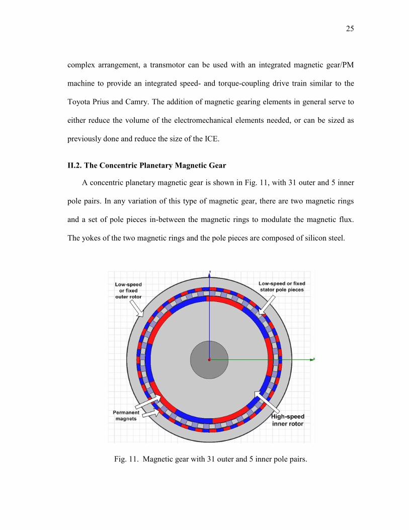
A concentric planetary magnetic gear is shown in Fig. 11, with 31 outer and 5 inner
pole pairs. In any variation of this type of magnetic gear, there are two magnetic rings
and a set of pole pieces in-between the magnetic rings to modulate the magnetic flux.
The yokes of the two magnetic rings and the pole pieces are composed of silicon steel.
Fig. 11. Magnetic gear with 31 outer and 5 inner pole pairs.
26
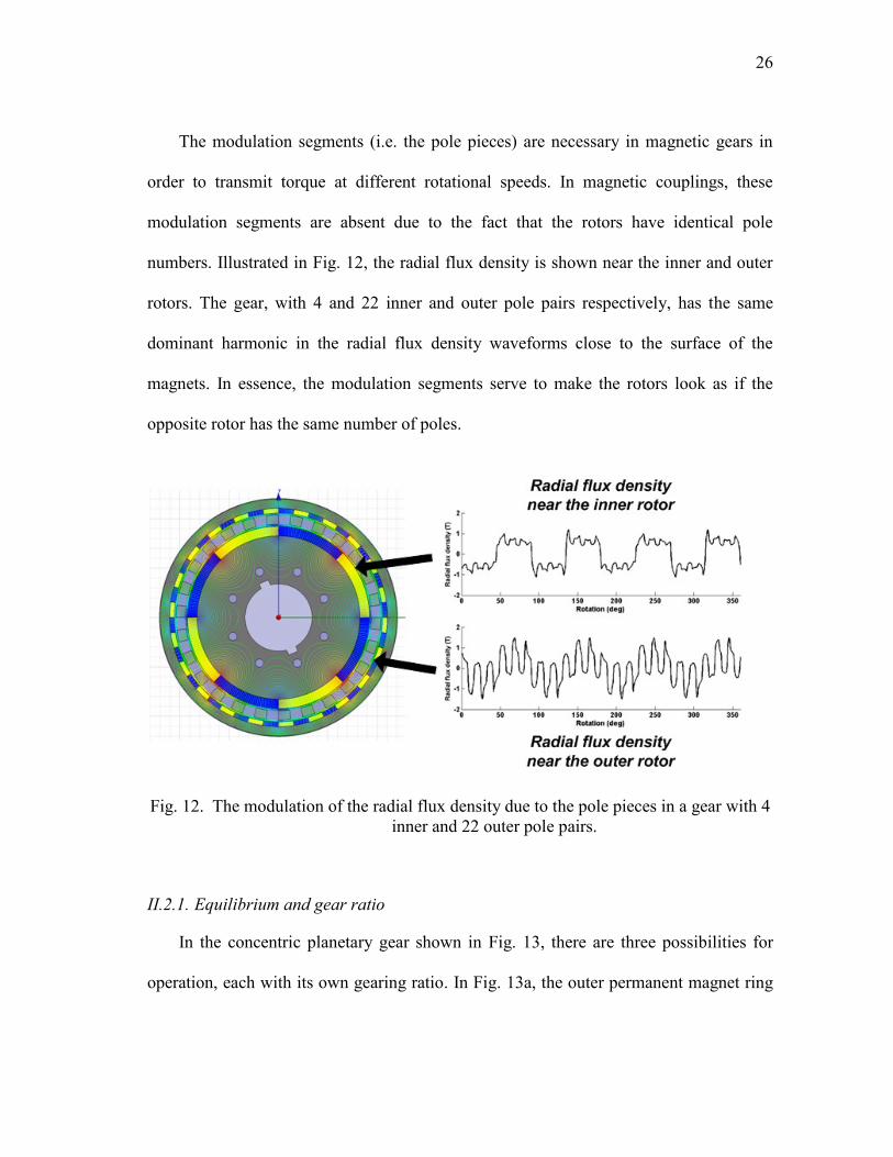
The modulation segments (i.e. the pole pieces) are necessary in magnetic gears in
order to transmit torque at different rotational speeds. In magnetic couplings, these
modulation segments are absent due to the fact that the rotors have identical pole
numbers. Illustrated in Fig. 12, the radial flux density is shown near the inner and outer
rotors. The gear, with 4 and 22 inner and outer pole pairs respectively, has the same
dominant harmonic in the radial flux density waveforms close to the surface of the
magnets. In essence, the modulation segments serve to make the rotors look as if the
opposite rotor has the same number of poles.
Fig. 12. The modulation of the radial flux density due to the pole pieces in a gear with 4
inner and 22 outer pole pairs.
II.2.1. Equilibrium and gear ratio
In the concentric planetary gear shown in Fig. 13, there are three possibilities for
operation, each with its own gearing ratio. In Fig. 13a, the outer permanent magnet ring

27
is fixed, while the stator pieces and inner permanent magnet ring rotate concurrently. In
Fig. 13b, the stator pieces are fixed while the two permanent magnet rings are counter-
rotated. In Fig. 13c, the inner magnetic ring is fixed while the outer magnetic ring and
stator pieces rotate concurrently. At the same time, the pole combination for the outer
permanent magnet and inner permanent magnet rings should be considered. The
combination of pole pairs can determine not only the gear ratio, but also the amount of
ripple in the torque transmission. In certain applications a high amount of torque ripple
may not be acceptable. However, there could be a trade-off to keep the gear ratio high in
order to reduce the size of the generator.
(a) (b) (c)
Fig. 13. Assembly showing (a) outer magnetic ring fixed, (b) stator segments fixed, and
(c) inner magnetic ring fixed.
The gearing ratios are derived by the process given in [4]. Using a Fourier series for
the radial flux density due to the magnets, as well as a modulation function to account
for the pole pieces, it is shown that a general Willis equation emerges for the magnetic
gear, shown in (8). In (8), m is the order of the space harmonic components and k is the
order of space harmonic components due to the introduction of the pole pieces. Indeed,
28
the mechanical planetary gear components have duals in the magnetic gear. The carrier
is a dual to the modulation segments, while the sun gear and ring gear are duals to the
inner and outer rotors respectively.
s
s
sr
s
kmknmp
kn
knmp
mp
, (8)
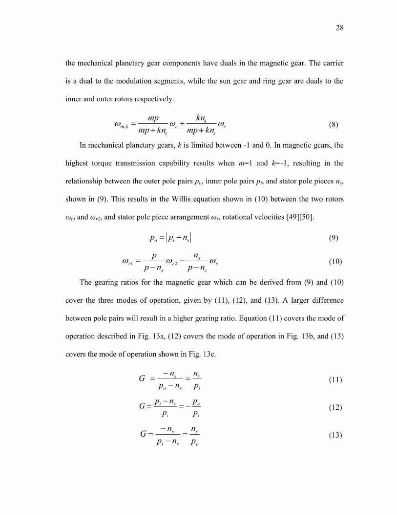
In mechanical planetary gears, k is limited between -1 and 0. In magnetic gears, the
highest torque transmission capability results when m=1 and k=-1, resulting in the
relationship between the outer pole pairs po, inner pole pairs pi, and stator pole pieces ns,
shown in (9). This results in the Willis equation shown in (10) between the two rotors
ωr1 and ωr2, and stator pole piece arrangement ωs, rotational velocities [49][50].
sio npp
(9)
s
s
sr
s
rnp
n
np
p
21 (10)
The gearing ratios for the magnetic gear which can be derived from (9) and (10)
cover the three modes of operation, given by (11), (12), and (13). A larger difference
between pole pairs will result in a higher gearing ratio. Equation (11) covers the mode of
operation described in Fig. 13a, (12) covers the mode of operation in Fig. 13b, and (13)
covers the mode of operation shown in Fig. 13c.
i
s
so
s
p
n
np
nG
(11)
i
o
i
si
p
p
p
npG
(12)
o
s
si
s
p
n
np
nG
(13)

29
The equilibrium point for the gear reveals behavioral characteristics of the gear. If
one rotor is fixed while the other is rotated, a torque will be exerted until the gear
reaches its stall torque rating, at which point it will slip to the next equilibrium point. If
the rotor is held below the stall point, and released, the rotor will oscillate between stall
points like a spring. This reveals the natural overload protection of the gear, a torque
exceeding the stall torque rating of the gear will cause it to slip. A simulation can reveal
the physical equilibrium points of the gear. The corresponding torque curves in Fig. 14,
representing the torque exerted on the two rotors, intersect at the equilibrium points.
Depending upon which rotor is held fixed, the movement required to make the other
rotor slip will behave according to the gear ratio.
Fig. 14. Torque curves revealing equilibrium points for the 22/4 magnetic gear.
30
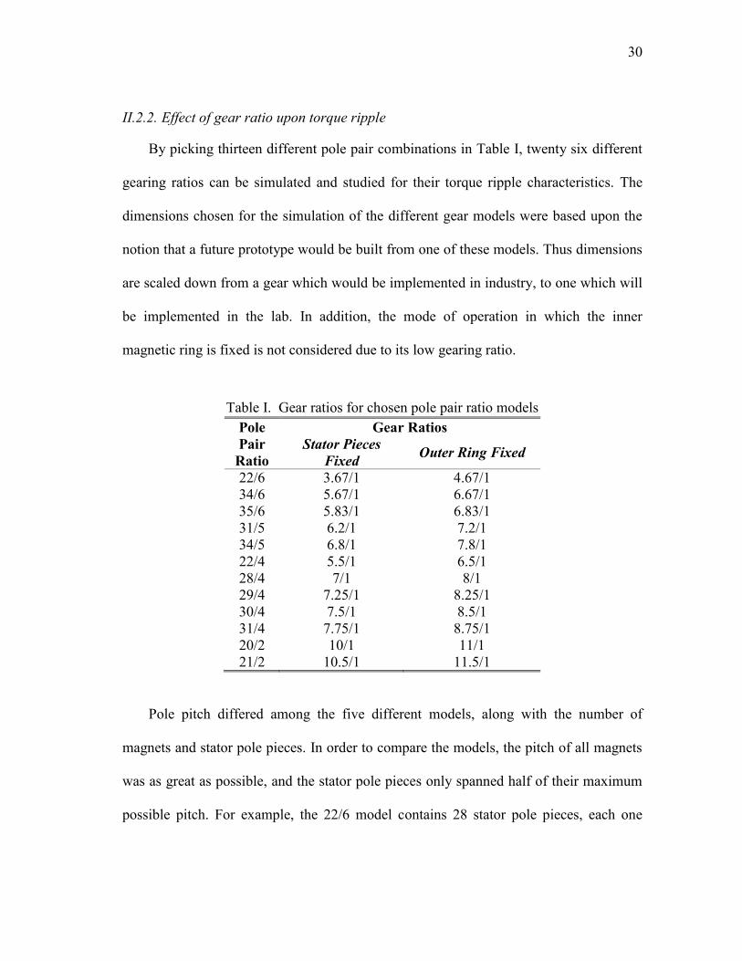
II.2.2. Effect of gear ratio upon torque ripple
By picking thirteen different pole pair combinations in Table I, twenty six different
gearing ratios can be simulated and studied for their torque ripple characteristics. The
dimensions chosen for the simulation of the different gear models were based upon the
notion that a future prototype would be built from one of these models. Thus dimensions
are scaled down from a gear which would be implemented in industry, to one which will
be implemented in the lab. In addition, the mode of operation in which the inner
magnetic ring is fixed is not considered due to its low gearing ratio.
Table I. Gear ratios for chosen pole pair ratio models
Pole
Pair
Ratio
Gear Ratios
Stator Pieces
Fixed Outer Ring Fixed
22/6 3.67/1 4.67/1
34/6 5.67/1 6.67/1
35/6 5.83/1 6.83/1
31/5 6.2/1 7.2/1
34/5 6.8/1 7.8/1
22/4 5.5/1 6.5/1
28/4 7/1 8/1
29/4 7.25/1 8.25/1
30/4 7.5/1 8.5/1
31/4 7.75/1 8.75/1
20/2 10/1 11/1
21/2 10.5/1 11.5/1
Pole pitch differed among the five different models, along with the number of
magnets and stator pole pieces. In order to compare the models, the pitch of all magnets
was as great as possible, and the stator pole pieces only spanned half of their maximum
possible pitch. For example, the 22/6 model contains 28 stator pole pieces, each one

31
having a pitch of 6.43º. The dimensions which are common to all the models are given in
Table II.
With the chosen dimensions and parameters for the different gear models,
simulations are setup in Maxwell. The magnets used in the simulation are composed of
Neodymium from Ansoft‟s built-in library, and radially-magnetized. The yokes for the
outer and inner rotors are composed of AK Steel M-45 non-oriented electrical steel. The
stator pole pieces are composed of AK Steel M-6 grain-oriented electrical steel.
Table II. Dimensions for models in preliminary gearing ratio analysis
Parameter Value [mm]
Outer radius of inner rotor yoke 93
Inner radius of outer rotor yoke 115
Outer radius of outer rotor yoke 130
Outer radius of the stator pole pieces 109
Inner radius of the stator pole pieces 102
Shaft radius 30
Stack length 50
Magnet thickness on inner rotor 8
Magnet thickness on outer rotor 5
Care must be taken to note the starting position for the gear simulation. The starting
point was determined by looking for the equilibrium points for a gear. A simulation in
which one rotor was rotated while keeping the stator pieces and the other rotor fixed was
executed. The outer rotor was rotated two full pole pitches in 1 second.
Determining the speed at which to compare the models involved looking at different
speeds and their torque ripple characteristics. In Fig. 15, the 22/4 combination gear was
given a step change in speed, beginning at 50 rpm on the inner rotor, then increasing to
150 rpm at 0.5 s. From looking at the torque transfer plot in Fig. 15, it is evident that the
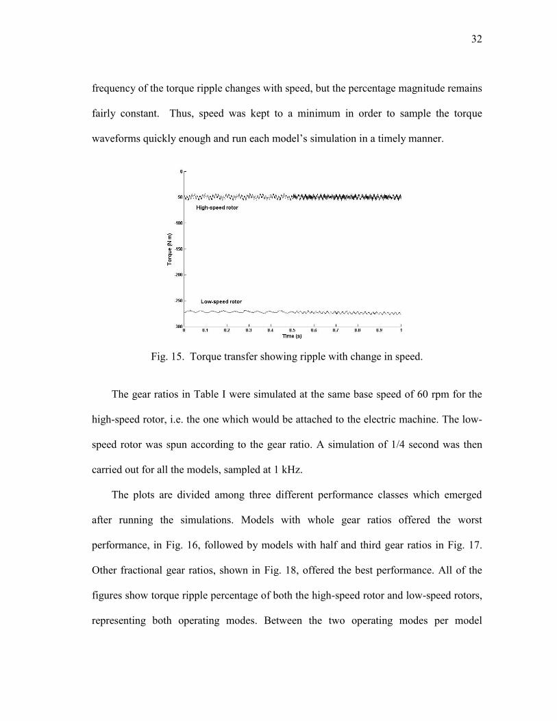
32
frequency of the torque ripple changes with speed, but the percentage magnitude remains
fairly constant. Thus, speed was kept to a minimum in order to sample the torque
waveforms quickly enough and run each model‟s simulation in a timely manner.
Fig. 15. Torque transfer showing ripple with change in speed.
The gear ratios in Table I were simulated at the same base speed of 60 rpm for the
high-speed rotor, i.e. the one which would be attached to the electric machine. The low-
speed rotor was spun according to the gear ratio. A simulation of 1/4 second was then
carried out for all the models, sampled at 1 kHz.
The plots are divided among three different performance classes which emerged
after running the simulations. Models with whole gear ratios offered the worst
performance, in Fig. 16, followed by models with half and third gear ratios in Fig. 17.
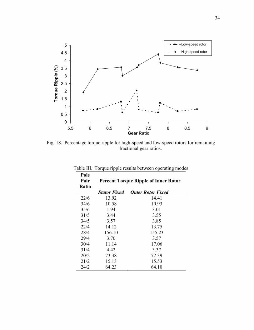
Other fractional gear ratios, shown in Fig. 18, offered the best performance. All of the
figures show torque ripple percentage of both the high-speed rotor and low-speed rotors,
representing both operating modes. Between the two operating modes per model
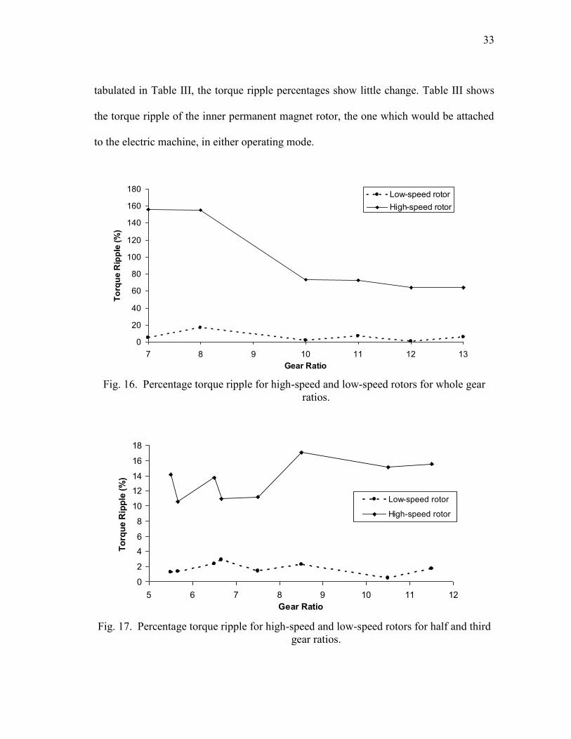
33
tabulated in Table III, the torque ripple percentages show little change. Table III shows
the torque ripple of the inner permanent magnet rotor, the one which would be attached
to the electric machine, in either operating mode.
Fig. 16. Percentage torque ripple for high-speed and low-speed rotors for whole gear
ratios.
Fig. 17. Percentage torque ripple for high-speed and low-speed rotors for half and third
gear ratios.
0
20
40
60
80
100
120
140
160
180
7 8 9 10 11 12 13
Gear Ratio
To
rqu
e R
ipp
le (
%)
Low-speed rotor
High-speed rotor
0
2
4
6
8
10
12
14
16
18
5 6 7 8 9 10 11 12
Gear Ratio
To
rqu
e R
ipp
le (
%)
Low-speed rotor
High-speed rotor
34
Fig. 18. Percentage torque ripple for high-speed and low-speed rotors for remaining
fractional gear ratios.
Table III. Torque ripple results between operating modes
Pole
Pair
Ratio
Percent Torque Ripple of Inner Rotor
Stator Fixed Outer Rotor Fixed
22/6 13.92 14.41
34/6 10.58 10.93
35/6 1.94 3.01
31/5 3.44 3.55
34/5 3.57 3.85
22/4 14.12 13.75
28/4 156.10 155.23
29/4 3.70 3.57
30/4 11.14 17.06
31/4 4.42 3.37
20/2 73.38 72.39
21/2 15.13 15.53
24/2 64.23 64.10
0
0.5
1
1.5
2
2.5
3
3.5
4
4.5
5
5.5 6 6.5 7 7.5 8 8.5 9Gear Ratio
To
rqu
e R
ipp
le (
%)
Low-speed rotor
High-speed rotor

35
Torque ripple in the modeled gears is caused by the interaction of the permanent
magnets with the stator pole pieces [4]. The causes of the high torque ripple among
whole gear ratios compared to fractional gear ratios can be understood better by
examining common multiples between pole pairs. In gears with the worst performance,
the dominant order of the torque ripple waveform was one or two times the value of the
least common multiple between the number of inner pole pairs, pi, and the poles on the
low-speed rotor. This would either be the number of stator pole pieces, ns, given by LCM
(pi, ns) for fixed-stator operation. Or it could be the number of pole pairs on the outer
rotor, po, given by LCM (po, pi) for fixed outer-rotor operation.
A higher value of the least common multiple would result in a higher fundamental
order of the cogging torque waveform, and less ripple percentage. This correlates well
with the torque results by looking at the least common multiple for the gear with the
worst performance, 28/4, which has a least common multiple of 32, for fixed stator
operation, and 28 for fixed outer-rotor operation. Fig. 19 shows torque transfer
waveforms for both modes of operation in the 28/4 gear. The gear with the best
performance, 35/6, has a least common multiple of 246 for fixed-stator operation, and
210 for fixed outer-rotor operation.
This suggests that higher gear ratios will naturally have higher least common
multiples, and thus a higher torque ripple fundamental order. However, there remains a
practical limit to the amount of pole pairs which can be placed on the outer rotor. As
shown in Fig. 20, there are leakage flux paths which circulate between adjacent magnets

36
on both magnetic rings. Increasing the number of pole pairs on the outer rotor would
increase the number of leakage flux paths and contribute to losses in the magnets.
(a)
(b)
Fig. 19. Torque transfer in 28/4 gear for (a) fixed stator and (b) fixed outer rotor
operation.
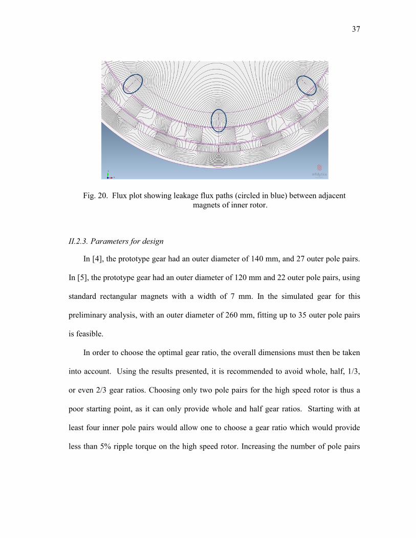
37
Fig. 20. Flux plot showing leakage flux paths (circled in blue) between adjacent
magnets of inner rotor.
II.2.3. Parameters for design
In [4], the prototype gear had an outer diameter of 140 mm, and 27 outer pole pairs.
In [5], the prototype gear had an outer diameter of 120 mm and 22 outer pole pairs, using
standard rectangular magnets with a width of 7 mm. In the simulated gear for this
preliminary analysis, with an outer diameter of 260 mm, fitting up to 35 outer pole pairs
is feasible.
In order to choose the optimal gear ratio, the overall dimensions must then be taken
into account. Using the results presented, it is recommended to avoid whole, half, 1/3,
or even 2/3 gear ratios. Choosing only two pole pairs for the high speed rotor is thus a
poor starting point, as it can only provide whole and half gear ratios. Starting with at
least four inner pole pairs would allow one to choose a gear ratio which would provide
less than 5% ripple torque on the high speed rotor. Increasing the number of pole pairs
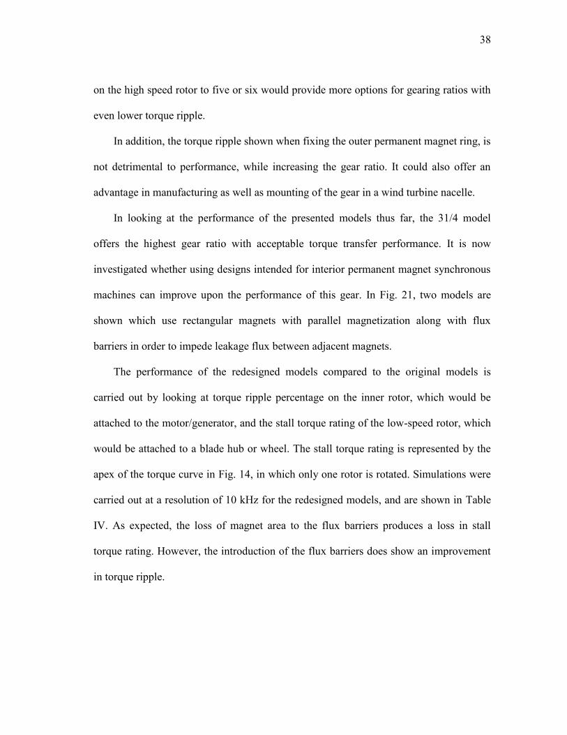
38
on the high speed rotor to five or six would provide more options for gearing ratios with
even lower torque ripple.
In addition, the torque ripple shown when fixing the outer permanent magnet ring, is
not detrimental to performance, while increasing the gear ratio. It could also offer an
advantage in manufacturing as well as mounting of the gear in a wind turbine nacelle.
In looking at the performance of the presented models thus far, the 31/4 model
offers the highest gear ratio with acceptable torque transfer performance. It is now
investigated whether using designs intended for interior permanent magnet synchronous
machines can improve upon the performance of this gear. In Fig. 21, two models are
shown which use rectangular magnets with parallel magnetization along with flux
barriers in order to impede leakage flux between adjacent magnets.
The performance of the redesigned models compared to the original models is
carried out by looking at torque ripple percentage on the inner rotor, which would be
attached to the motor/generator, and the stall torque rating of the low-speed rotor, which
would be attached to a blade hub or wheel. The stall torque rating is represented by the
apex of the torque curve in Fig. 14, in which only one rotor is rotated. Simulations were
carried out at a resolution of 10 kHz for the redesigned models, and are shown in Table
IV. As expected, the loss of magnet area to the flux barriers produces a loss in stall
torque rating. However, the introduction of the flux barriers does show an improvement
in torque ripple.
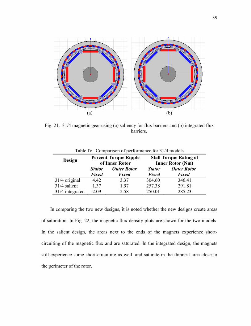
39
(a) (b)
Fig. 21. 31/4 magnetic gear using (a) saliency for flux barriers and (b) integrated flux
barriers.
Table IV. Comparison of performance for 31/4 models
Design Percent Torque Ripple
of Inner Rotor
Stall Torque Rating of
Inner Rotor (Nm)
Stator
Fixed
Outer Rotor
Fixed
Stator
Fixed
Outer Rotor
Fixed
31/4 original 4.42 3.37 304.60 346.41
31/4 salient 1.37 1.97 257.38 291.81
31/4 integrated 2.09 2.58 250.01 285.23
In comparing the two new designs, it is noted whether the new designs create areas
of saturation. In Fig. 22, the magnetic flux density plots are shown for the two models.
In the salient design, the areas next to the ends of the magnets experience short-
circuiting of the magnetic flux and are saturated. In the integrated design, the magnets
still experience some short-circuiting as well, and saturate in the thinnest area close to
the perimeter of the rotor.

40
(a) (b)
Fig. 22. 31/4 magnetic gear using (a) saliency for flux barriers and (b) integrated flux
barriers.
II.3. Conclusion
Magnetic gear models have been presented and simulated with FEA to study the
effects of different pole pair ratios and operating modes on the performance of each gear.
It has been found that fractional gear ratios offer the best performance, with an option to
increase the gear ratio by fixing the outer permanent magnet ring.
It has also been shown that the design of the high-speed rotor can benefit from
techniques used for interior permanent magnet synchronous machine design. The torque
ripple can be reduced at the cost of a lower stall torque rating for the gear.
The wind energy industry, along with electric vehicle traction, will continue to grow
in production as well as research in the coming years. With the demanded increase in
sustainable energy production and efficiency from automobiles, a significant
improvement can be made by migrating from mechanical components to
41
electromechanical ones. With this migration, future wind turbines and cars can continue
to improve with maintenance reduction, noise reduction, and increased reliability.
Future marine applications will benefit from electric propulsion systems which have
higher torque densities. These systems will facilitate more powerful pod propulsion
systems as well as reduce the volume and weight imposed by machines in conventional
drive trains. Modern machines, in an effort to increase torque density, have moved into
the arena of rare-earth permanent magnets as well as High Temperature Superconducting
coils. While these technologies have exhibited exceptional torque densities to date,
magnetic gears can further increase the torque densities of electric propulsion systems
and bring higher efficiency and reliability to marine vessels.

42
III. ANALYSIS OF THE MAGNETIC GEAR WITH WINDING FUNCTION
THEORY
The analysis of magnetic gears has progressed from that of very simple
arrangements to more complex magnetic gears which are currently being studied. Early
analysis was carried out on the simplest arrangements for magnetically coupled
elements, the 1:1 coaxial coupling and the spur gear. This early work done in [51]-[54]
was carried out by using a combination of magnetic field theory and FEA. Magnetic
field theory was used in conjunction with Fourier series for the radial and
circumferential fields due to the magnets in order to calculate torque. Analysis in [54]
calculated the torque in the spur gear by using parallel and radial magnetization vectors
for the individual magnets, in which the parallel magnetization was found to give a
higher stall torque. This same analysis was applied in [11] to the cycloid gear.
The idealized gear layout, shown in Fig. 23, is comprised of two magnetic rings, and
stator pole pieces made of silicon steel between the magnetic rings. There are two modes
of operation achieved by either mechanically grounding the stator pole pieces or the
outer magnetic ring. The analysis carried out will assume the mode of operation in which
the stator pole pieces are mechanically grounded, allowing the magnetic rings to
counter-rotate.
This gear has also been analyzed using magnetic field theory in [55]-[57]. The
results calculated are very close to that found with FEA. However, a new method of
analyzing the gear with considerably less computational burden is needed. This new
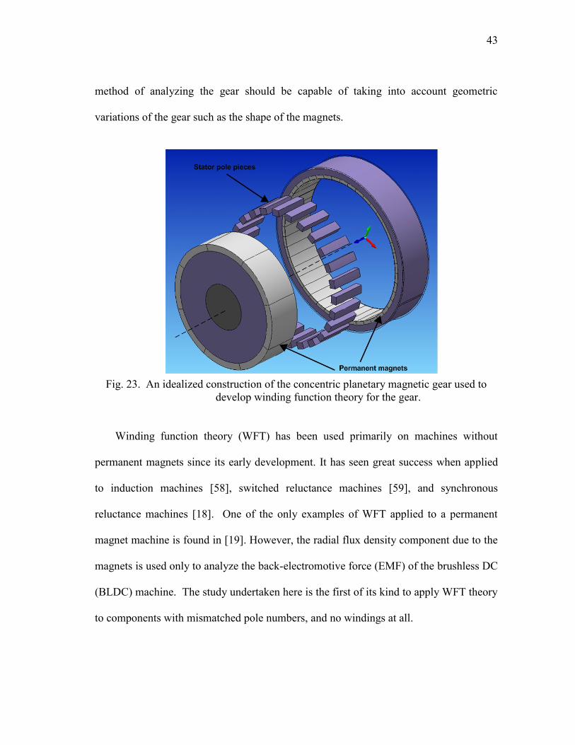
43
method of analyzing the gear should be capable of taking into account geometric
variations of the gear such as the shape of the magnets.
Fig. 23. An idealized construction of the concentric planetary magnetic gear used to
develop winding function theory for the gear.
Winding function theory (WFT) has been used primarily on machines without
permanent magnets since its early development. It has seen great success when applied
to induction machines [58], switched reluctance machines [59], and synchronous
reluctance machines [18]. One of the only examples of WFT applied to a permanent
magnet machine is found in [19]. However, the radial flux density component due to the
magnets is used only to analyze the back-electromotive force (EMF) of the brushless DC
(BLDC) machine. The study undertaken here is the first of its kind to apply WFT theory
to components with mismatched pole numbers, and no windings at all.
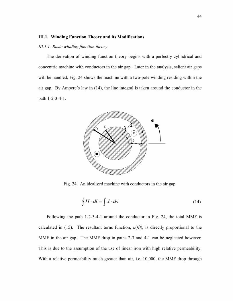
44
III.1. Winding Function Theory and its Modifications
III.1.1. Basic winding function theory
The derivation of winding function theory begins with a perfectly cylindrical and
concentric machine with conductors in the air gap. Later in the analysis, salient air gaps
will be handled. Fig. 24 shows the machine with a two-pole winding residing within the
air gap. By Ampere‟s law in (14), the line integral is taken around the conductor in the
path 1-2-3-4-1.
Fig. 24. An idealized machine with conductors in the air gap.
dsJdlH (14)
Following the path 1-2-3-4-1 around the conductor in Fig. 24, the total MMF is
calculated in (15). The resultant turns function, n(Φ), is directly proportional to the
MMF in the air gap. The MMF drop in paths 2-3 and 4-1 can be neglected however.
This is due to the assumption of the use of linear iron with high relative permeability.
With a relative permeability much greater than air, i.e. 10,000, the MMF drop through

45
the iron is then neglected, leaving the two terms in (16). The magnetic field strength
around the air gap, H(Φ), is thus a function of the turns function, in (17).
in )(41342312 (15)
)0()0()()0,(12 gHHrrdrrH sr
r
r
r
s
)()()(),(34 gHHrrdrrH rs
r
r
s
r
(16)
)0()()( Hg
inH
(17)
Using Gauss‟ law in (18), the value for the magnetic field strength around the air
gap can be found. This assumes a fictitious cylinder encompassing only the rotor of the
ideal machine.
l
dzrdHdsB0
2
0
0 )(0
0)(
2
0
0
dHlr
(18)
One of the key assumptions of normal winding function theory follows from (18), in
that the value of the MMF taken around the circumference of the machine must have no
average component, shown in (19).
0)(
2
0
34
d (19)
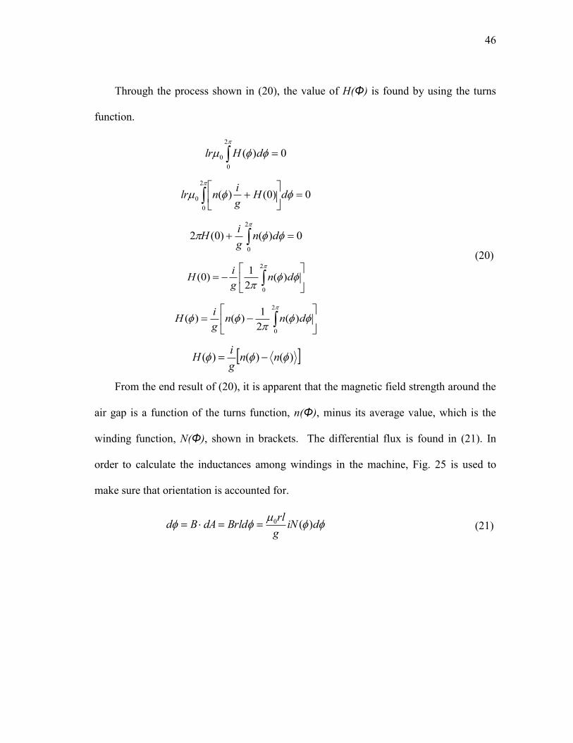
46
Through the process shown in (20), the value of H(Φ) is found by using the turns
function.
2
0
0 0)( dHlr
0)0()(
2
0
0
dHg
inlr
0)()0(2
2
0
dng
iH
2
0
)(2
1)0( dn
g
iH
2
0
)(2
1)()( dnn
g
iH
)()()( nng
iH
(20)
From the end result of (20), it is apparent that the magnetic field strength around the
air gap is a function of the turns function, n(Φ), minus its average value, which is the
winding function, N(Φ), shown in brackets. The differential flux is found in (21). In
order to calculate the inductances among windings in the machine, Fig. 25 is used to
make sure that orientation is accounted for.
diNg
rlBrlddABd )(0 (21)
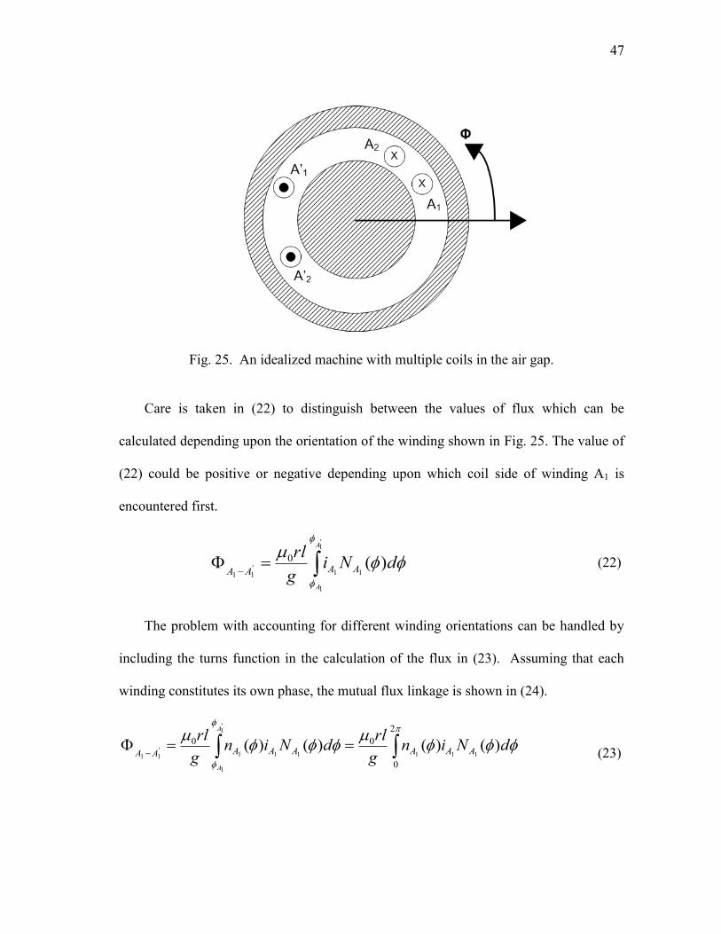
47
Fig. 25. An idealized machine with multiple coils in the air gap.
Care is taken in (22) to distinguish between the values of flux which can be
calculated depending upon the orientation of the winding shown in Fig. 25. The value of
(22) could be positive or negative depending upon which coil side of winding A1 is
encountered first.
'1
1
11'11
)(0
A
A
dNig
rlAAAA
(22)
The problem with accounting for different winding orientations can be handled by
including the turns function in the calculation of the flux in (23). Assuming that each
winding constitutes its own phase, the mutual flux linkage is shown in (24).
2
0
00 )()()()(111
'1
1
111'11
dNing
rldNin
g
rlAAAAAAAA
A
A
(23)
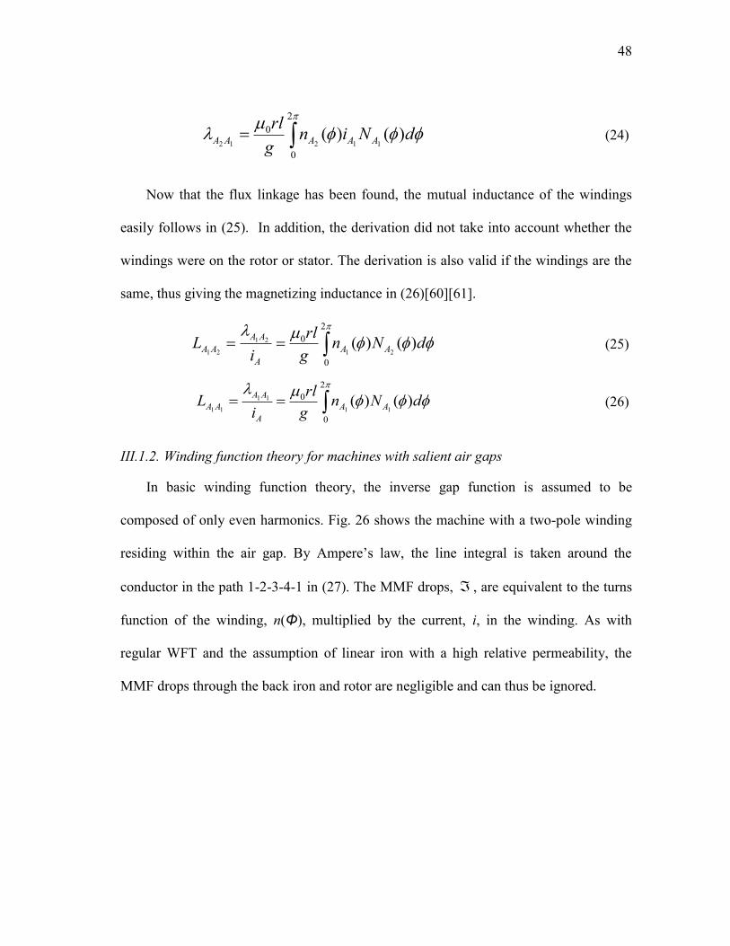
48
2
0
0 )()(11212
dNing
rlAAAAA (24)
Now that the flux linkage has been found, the mutual inductance of the windings
easily follows in (25). In addition, the derivation did not take into account whether the
windings were on the rotor or stator. The derivation is also valid if the windings are the
same, thus giving the magnetizing inductance in (26)[60][61].
dNng
rl
iL AA
A
AA
AA )()(21
21
21
2
0
0
(25)
dNng
rl
iL AA
A
AA
AA )()(11
11
11
2
0
0
(26)
III.1.2. Winding function theory for machines with salient air gaps
In basic winding function theory, the inverse gap function is assumed to be
composed of only even harmonics. Fig. 26 shows the machine with a two-pole winding
residing within the air gap. By Ampere‟s law, the line integral is taken around the
conductor in the path 1-2-3-4-1 in (27). The MMF drops, , are equivalent to the turns
function of the winding, n(Φ), multiplied by the current, i, in the winding. As with
regular WFT and the assumption of linear iron with a high relative permeability, the
MMF drops through the back iron and rotor are negligible and can thus be ignored.
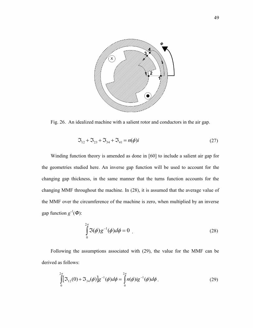
49
Fig. 26. An idealized machine with a salient rotor and conductors in the air gap.
in )(41342312 (27)
Winding function theory is amended as done in [60] to include a salient air gap for
the geometries studied here. An inverse gap function will be used to account for the
changing gap thickness, in the same manner that the turns function accounts for the
changing MMF throughout the machine. In (28), it is assumed that the average value of
the MMF over the circumference of the machine is zero, when multiplied by an inverse
gap function g-1
(Φ):
2
0
1 0)()( dg . (28)
Following the assumptions associated with (29), the value for the MMF can be
derived as follows:
2
0
1
2
0
1
3412 )()()()()0( digndg . (29)
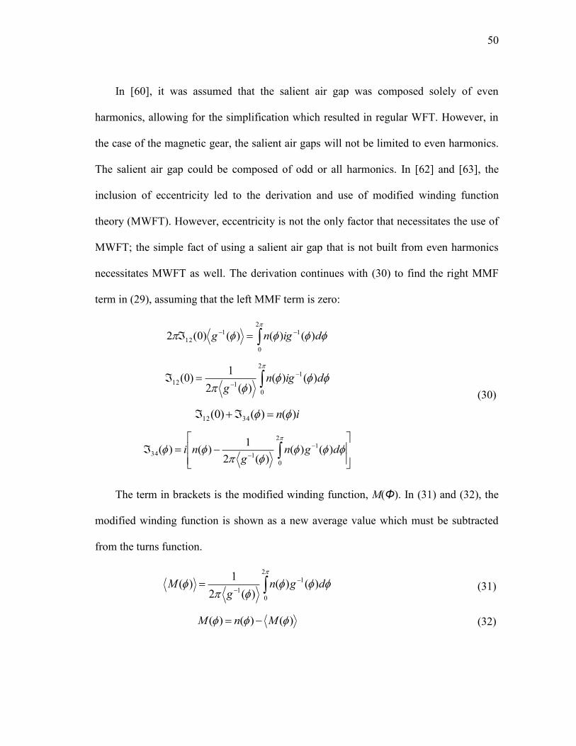
50
In [60], it was assumed that the salient air gap was composed solely of even
harmonics, allowing for the simplification which resulted in regular WFT. However, in
the case of the magnetic gear, the salient air gaps will not be limited to even harmonics.
The salient air gap could be composed of odd or all harmonics. In [62] and [63], the
inclusion of eccentricity led to the derivation and use of modified winding function
theory (MWFT). However, eccentricity is not the only factor that necessitates the use of
MWFT; the simple fact of using a salient air gap that is not built from even harmonics
necessitates MWFT as well. The derivation continues with (30) to find the right MMF
term in (29), assuming that the left MMF term is zero:
2
0
11
12 )()()()0(2 digng
2
0
1
112 )()()(2
1)0( dign
g
in )()()0( 3412
2
0
1
134 )()()(2
1)()( dgn
gni
(30)
The term in brackets is the modified winding function, M(Φ). In (31) and (32), the
modified winding function is shown as a new average value which must be subtracted
from the turns function.
2
0
1
1)()(
)(2
1)( dgn
gM (31)
)()()( MnM
(32)

51
Assuming two windings A and B, a radius r, and a stack length l, the new
inductance values using the modified winding function are given in (33) for the mutual
inductance and in (34) for the magnetizing inductance. The flux linkage AB is the flux
in winding A due to the current in winding B, while the flux linkage AA is the flux in
winding A due to its own current.
2
0
1
0 )()()( dgMnrli
L BA
B
ABAB
(33)
2
0
1
0 )()()( dgMnrli
L AA
A
AAAA
(34)
III.2. Winding Function Theory Applied to Magnetic Devices
Now that the need for MWFT has been presented, it will be applied to magnetic
devices. The modeling of a magnetic gear must begin with the most fundamental
component of the gear, the individual magnets themselves, first looked at in [64] and
[65] in conjunction with FEA. In Fig. 27, a single magnet is shown with a magnetization
vector which is parallel to its thickness. A coil wrapped around a material of equal
permeability to that of the magnet will provide an equivalent magnetization vector,
assuming sufficient current. The magnets used in this analysis have a thickness, lm, of 2.5
mm and a remanent magnetism, Br, of 1.21 T. The magnets on the inner rotor are stacked
doubly compared to the outer rotor. Hence, the required MMF for one stack of magnets
is:

52
AtlB
lHr
mrmm 2288
052.1104
)0025.0(21.17
0
.
(35)
Fig. 27. Model of a permanent magnet with coils fed by DC current which produces an
equivalent magnetization vector.
In the simplest case, surface-mounted magnets on a rotor lie adjacent to each other
and form the basis for a single turns function, as visualized in Fig. 28. The adjacent
magnets are simply modeled as coils which are wrapped in opposing directions adjacent
to each other. They are fed equivalent DC current because magnets on the same rotor
will all have the same thickness in the magnetic gear. These assumptions allow us to
treat the adjacent magnets as though they are part of a single phase. The turns function
reaches a magnitude of 2N if each magnet has N windings. This is due to the fact that
adjacent coil sides lie next to each other to create alternating magnetic flux vectors.
Fig. 29 displays an 8-pole rotor with surface-mount magnets modeled as coils.
Assuming that the coil sides are infinitesimally narrow, the turns function resulting from
the rotor is also shown in Fig. 29 as a square wave. Since the magnets have a full pitch,
the resulting square wave is symmetric.

53
Fig. 28. Permanent magnets with alternating vectors form the basis for a single turns
function over the circumference of the rotor.
Fig. 29. An 8-pole rotor with infinitesimally narrow coil sides and its resulting turns
function.
The turns functions for the windings in this study are built from Fourier series,
given in (36) and shown in Fig. 30, which can be phase-shifted easily in simulations.
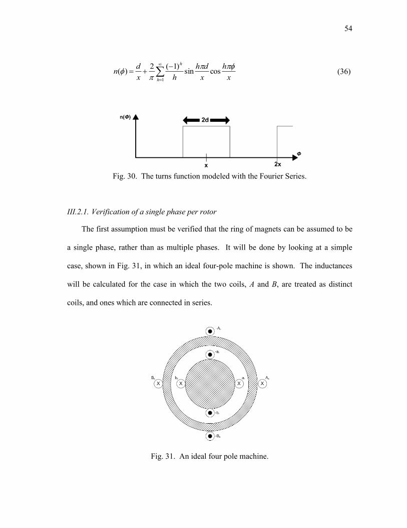
54
1
cossin)1(2
)(h
h
x
h
x
dh
hx
dn
(36)
Fig. 30. The turns function modeled with the Fourier Series.
III.2.1. Verification of a single phase per rotor
The first assumption must be verified that the ring of magnets can be assumed to be
a single phase, rather than as multiple phases. It will be done by looking at a simple
case, shown in Fig. 31, in which an ideal four-pole machine is shown. The inductances
will be calculated for the case in which the two coils, A and B, are treated as distinct
coils, and ones which are connected in series.
Fig. 31. An ideal four pole machine.

55
The turns functions and winding functions for the stator are shown in Fig. 32. The
two phases A and B are assumed to have N windings. The average value is used to turn
the turns function into the winding function. The average number is found in (37).
4)(
2
1)(
2
0
Ndnn
(37)
The self or magnetizing inductance is found in (38) for phase A.
8
3
44
3)( 20
2
0
2
2
222
0
020 Ng
rld
Nd
N
g
rldN
g
rlL AAA
(38)
Likewise, the mutual inductance is calculated in (39) between phases A and B.
8
1
4)( 20
23
0
2
0
0 Ng
rlNd
N
g
rldnN
g
rlL BAAB
(39)
Fig. 32. Turns and winding functions for stator phases.

56
The total flux treating A and B as separate phases is given by (40). This assumes
that the currents in the phases are equal, and that the mutual inductances are equivalent
as well. Then the total inductance is computed in (41).
AABAAABBAAABBBBAAAs iLiLiLiLiLiL 22 (40)
2
1
8
1
8
1
8
3
8
3 2020 Ng
rlN
g
rl
iL
s
ss
(41)
Now the inductance is calculated by treating the stator phases as a set of series
connected coils, done in (42). It is apparent that the inductance is the same as that found
in (41).
2
1
4
4 20
2
0
2
0 Ng
rld
N
g
rlLAB
(42)
III.2.2. Applying modified winding function theory to ideal machines
In transferring the proposed theory to the magnetic gear, MWFT will first be tested
on four different machines to verify its ability to account for machines with unmatched
pole numbers on the rotor and stator. These machines, shown in Fig. 33, represent the
four combinations between a stator with either 2 or 4 poles, and a rotor with 2 or 4 poles.
The ideal machine parameters are given in Table V. They are analyzed with FEA in
order to provide a basis for the inductance calculation using MWFT. The coil sides are
built as small as possible to mimic the assumptions taken in winding function theory.
Linear iron is used to mimic the assumption that the MMF drop through the iron is
negligible, i.e. saturation is not taken into account. In addition, the difference between
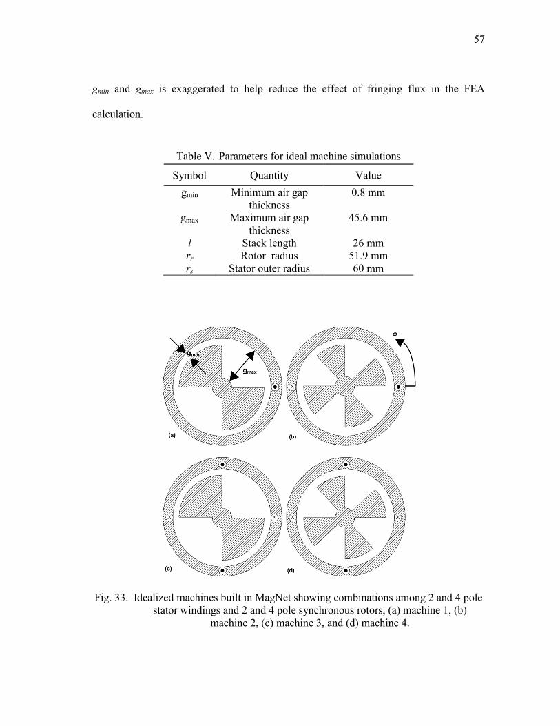
57
gmin and gmax is exaggerated to help reduce the effect of fringing flux in the FEA
calculation.
Table V. Parameters for ideal machine simulations
Symbol Quantity Value
gmin Minimum air gap
thickness
0.8 mm
gmax Maximum air gap
thickness
45.6 mm
l Stack length 26 mm
rr Rotor radius
51.9 mm
rs Stator outer radius 60 mm
Fig. 33. Idealized machines built in MagNet showing combinations among 2 and 4 pole
stator windings and 2 and 4 pole synchronous rotors, (a) machine 1, (b)
machine 2, (c) machine 3, and (d) machine 4.
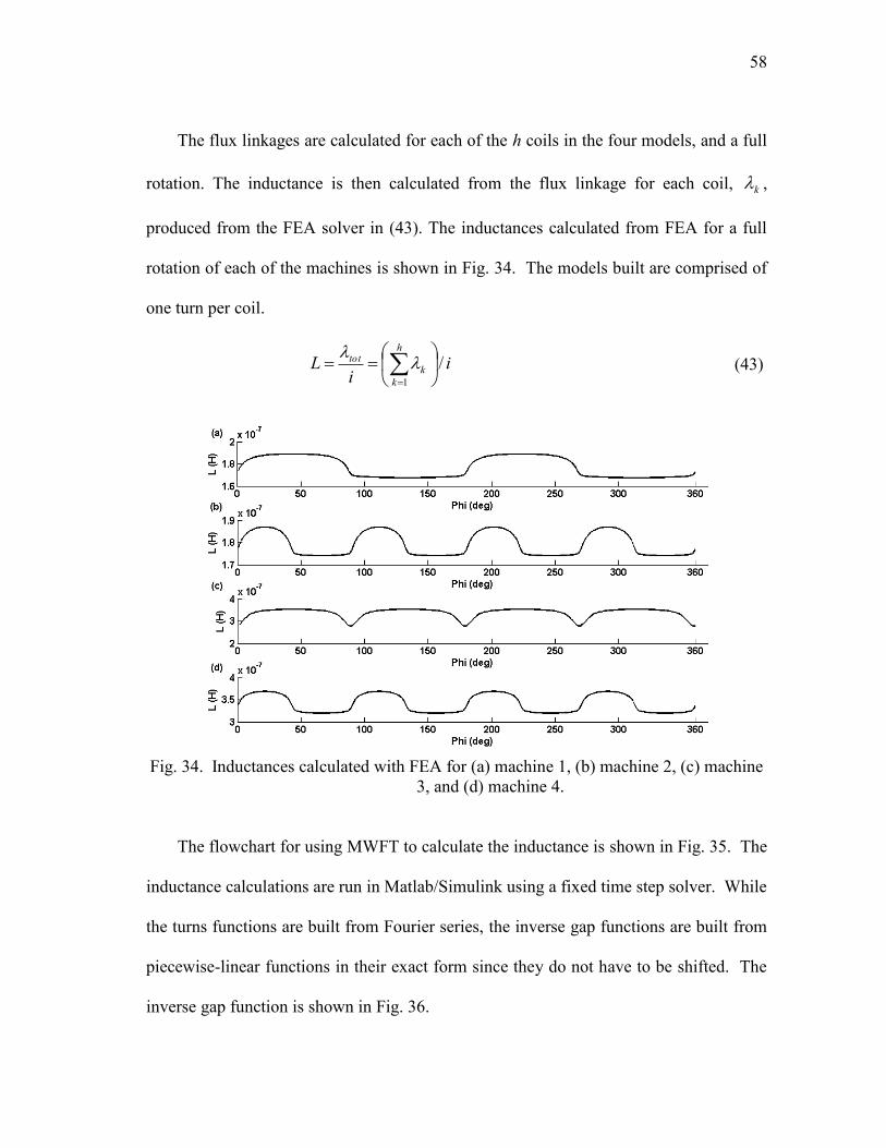
58
The flux linkages are calculated for each of the h coils in the four models, and a full
rotation. The inductance is then calculated from the flux linkage for each coil, k ,
produced from the FEA solver in (43). The inductances calculated from FEA for a full
rotation of each of the machines is shown in Fig. 34. The models built are comprised of
one turn per coil.
ii
Lh
k
ktot /
1
(43)
Fig. 34. Inductances calculated with FEA for (a) machine 1, (b) machine 2, (c) machine
3, and (d) machine 4.
The flowchart for using MWFT to calculate the inductance is shown in Fig. 35. The
inductance calculations are run in Matlab/Simulink using a fixed time step solver. While
the turns functions are built from Fourier series, the inverse gap functions are built from
piecewise-linear functions in their exact form since they do not have to be shifted. The
inverse gap function is shown in Fig. 36.
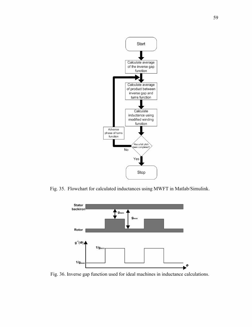
59
Fig. 35. Flowchart for calculated inductances using MWFT in Matlab/Simulink.
Fig. 36. Inverse gap function used for ideal machines in inductance calculations.
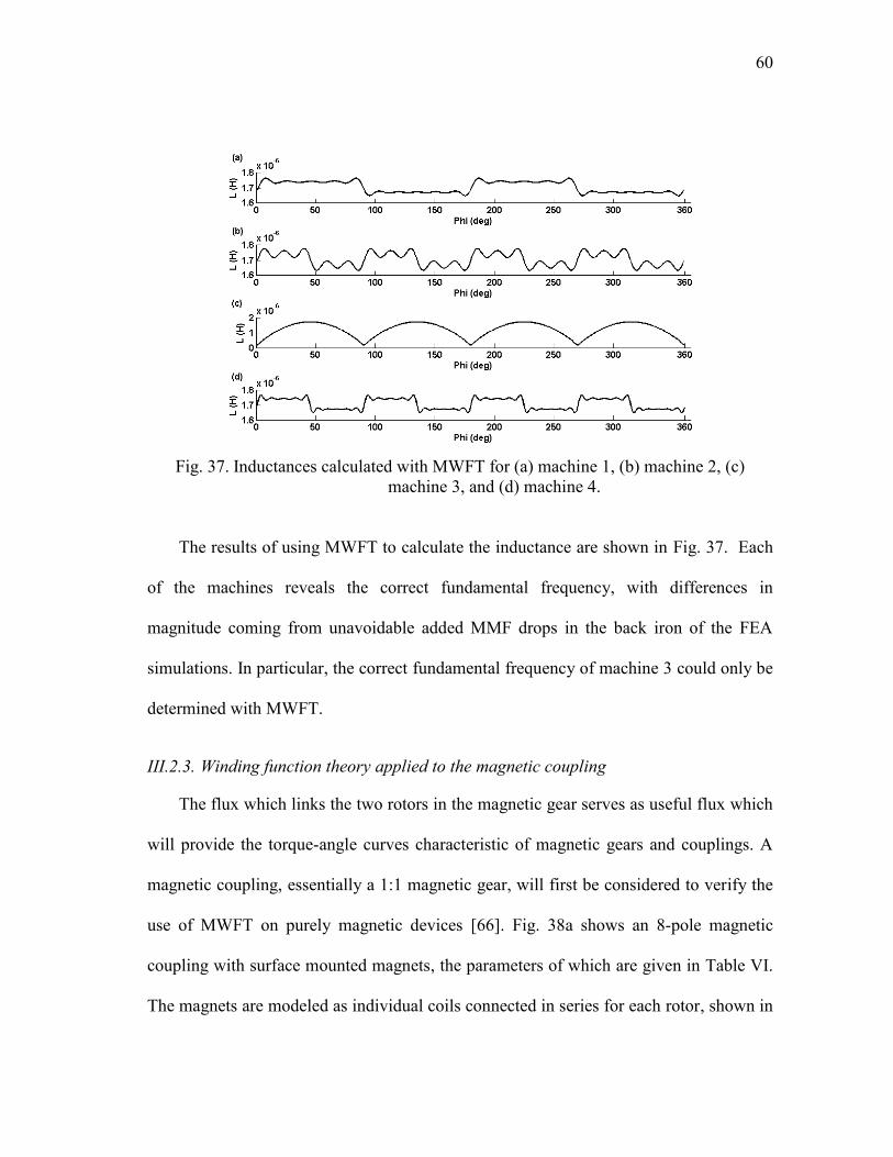
60
Fig. 37. Inductances calculated with MWFT for (a) machine 1, (b) machine 2, (c)
machine 3, and (d) machine 4.
The results of using MWFT to calculate the inductance are shown in Fig. 37. Each
of the machines reveals the correct fundamental frequency, with differences in
magnitude coming from unavoidable added MMF drops in the back iron of the FEA
simulations. In particular, the correct fundamental frequency of machine 3 could only be
determined with MWFT.
III.2.3. Winding function theory applied to the magnetic coupling
The flux which links the two rotors in the magnetic gear serves as useful flux which
will provide the torque-angle curves characteristic of magnetic gears and couplings. A
magnetic coupling, essentially a 1:1 magnetic gear, will first be considered to verify the
use of MWFT on purely magnetic devices [66]. Fig. 38a shows an 8-pole magnetic
coupling with surface mounted magnets, the parameters of which are given in Table VI.
The magnets are modeled as individual coils connected in series for each rotor, shown in

61
Fig. 38b. The coils are fed a DC current equivalent to twice that found in (35), due to
the fact that the magnets are 5 mm thick, and rotated one pole pair pitch.
Table VI. Parameters for 8-pole coupling
Quantity Value (mm)
Outer radius of outer rotor 60
Outer radius of inner rotor 46.3
Stack length 26
Shaft radius
17
Magnet thickness on either rotor 5
Air gap 1
(a) (b)
Fig. 38. 8-pole radial magnetic coupling with (a) permanent magnets and (b) coils.
Using a model with coils, the flux linkage is collected over a pole-pair rotation and
used to calculate the mutual inductance of the inner rotor due to the current in the outer
rotor, Lio, using (43). Lio is shown in Fig. 39, which is equivalent to the inductance of the
outer rotor due to the current in the inner rotor, Loi.
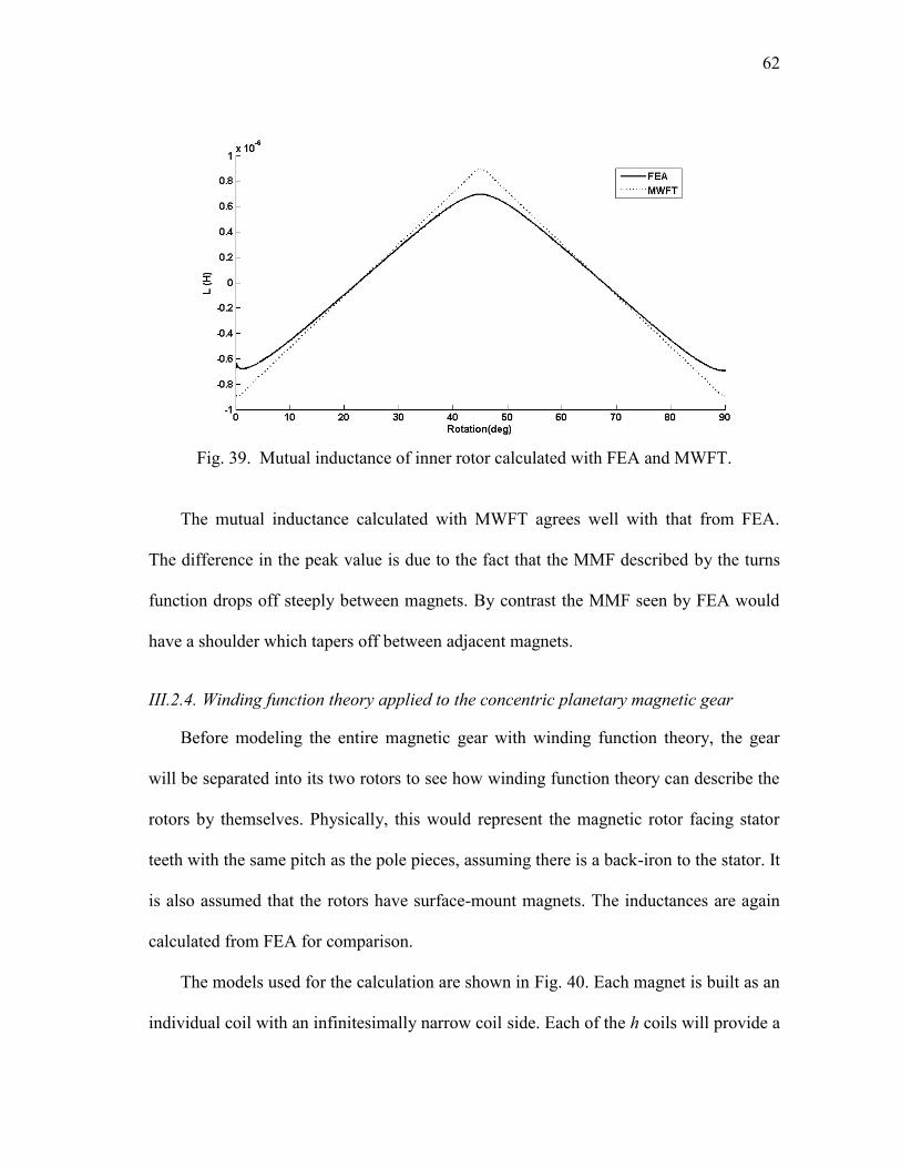
62
Fig. 39. Mutual inductance of inner rotor calculated with FEA and MWFT.
The mutual inductance calculated with MWFT agrees well with that from FEA.
The difference in the peak value is due to the fact that the MMF described by the turns
function drops off steeply between magnets. By contrast the MMF seen by FEA would
have a shoulder which tapers off between adjacent magnets.
III.2.4. Winding function theory applied to the concentric planetary magnetic gear
Before modeling the entire magnetic gear with winding function theory, the gear
will be separated into its two rotors to see how winding function theory can describe the
rotors by themselves. Physically, this would represent the magnetic rotor facing stator
teeth with the same pitch as the pole pieces, assuming there is a back-iron to the stator. It
is also assumed that the rotors have surface-mount magnets. The inductances are again
calculated from FEA for comparison.
The models used for the calculation are shown in Fig. 40. Each magnet is built as an
individual coil with an infinitesimally narrow coil side. Each of the h coils will provide a
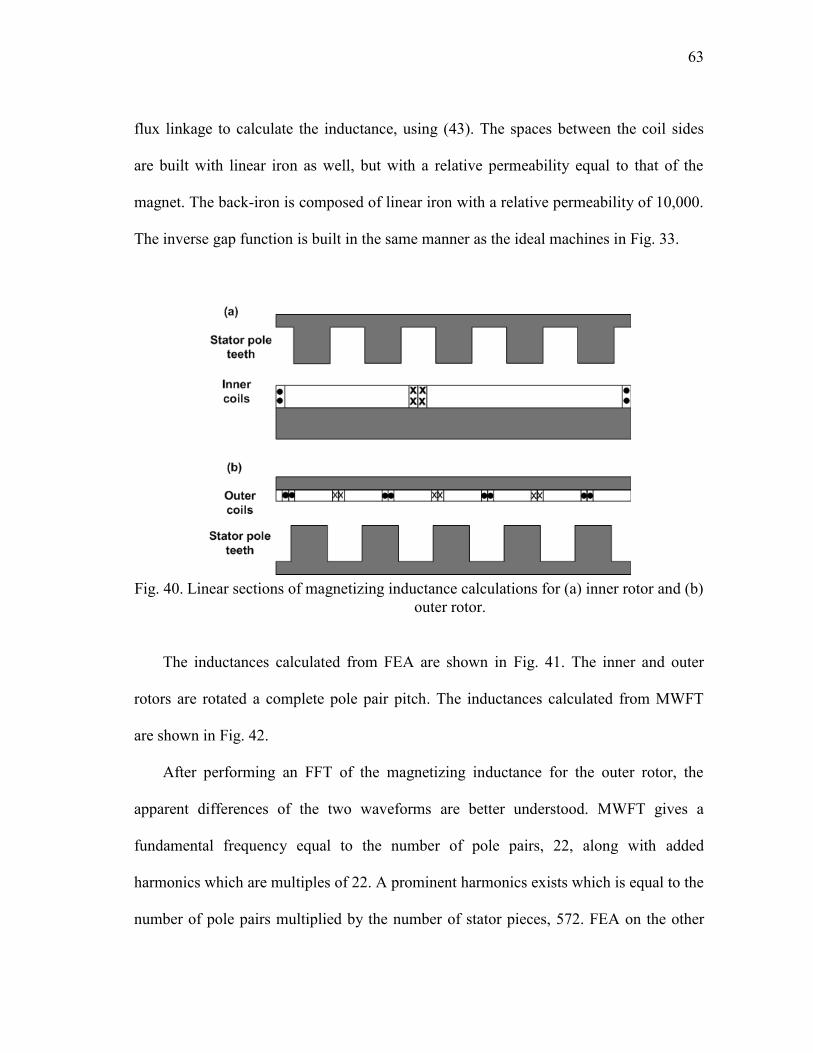
63
flux linkage to calculate the inductance, using (43). The spaces between the coil sides
are built with linear iron as well, but with a relative permeability equal to that of the
magnet. The back-iron is composed of linear iron with a relative permeability of 10,000.
The inverse gap function is built in the same manner as the ideal machines in Fig. 33.
Fig. 40. Linear sections of magnetizing inductance calculations for (a) inner rotor and (b)
outer rotor.
The inductances calculated from FEA are shown in Fig. 41. The inner and outer
rotors are rotated a complete pole pair pitch. The inductances calculated from MWFT
are shown in Fig. 42.
After performing an FFT of the magnetizing inductance for the outer rotor, the
apparent differences of the two waveforms are better understood. MWFT gives a
fundamental frequency equal to the number of pole pairs, 22, along with added
harmonics which are multiples of 22. A prominent harmonics exists which is equal to the
number of pole pairs multiplied by the number of stator pieces, 572. FEA on the other

64
hand gives a fundamental frequency equal to the number of poles, 44. FEA also shows
prominent harmonics which are even multiples of 44.
Fig. 41. Magnetizing inductances calculated with FEA for (a) inner rotor and (b) outer
rotor.
Fig. 42. Magnetizing inductances calculated with MWFT for (a) inner rotor and (b)
outer rotor.
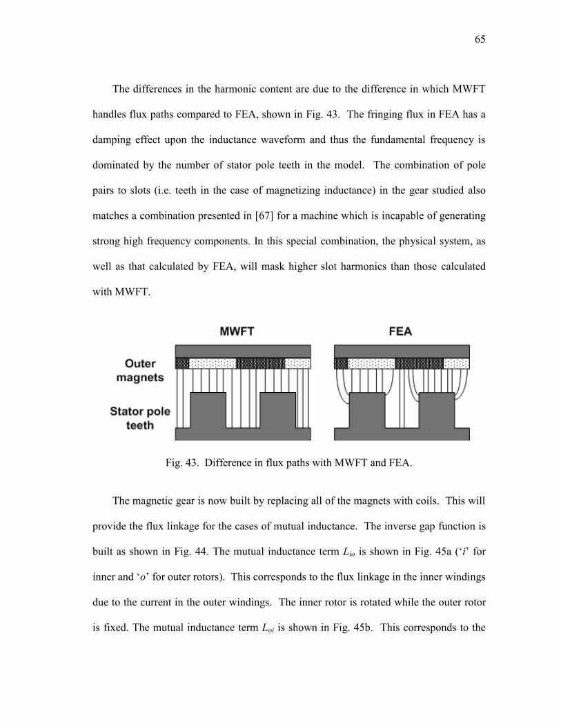
65
The differences in the harmonic content are due to the difference in which MWFT
handles flux paths compared to FEA, shown in Fig. 43. The fringing flux in FEA has a
damping effect upon the inductance waveform and thus the fundamental frequency is
dominated by the number of stator pole teeth in the model. The combination of pole
pairs to slots (i.e. teeth in the case of magnetizing inductance) in the gear studied also
matches a combination presented in [67] for a machine which is incapable of generating
strong high frequency components. In this special combination, the physical system, as
well as that calculated by FEA, will mask higher slot harmonics than those calculated
with MWFT.
Fig. 43. Difference in flux paths with MWFT and FEA.
The magnetic gear is now built by replacing all of the magnets with coils. This will
provide the flux linkage for the cases of mutual inductance. The inverse gap function is
built as shown in Fig. 44. The mutual inductance term Lio is shown in Fig. 45a („i‟ for
inner and „o‟ for outer rotors). This corresponds to the flux linkage in the inner windings
due to the current in the outer windings. The inner rotor is rotated while the outer rotor
is fixed. The mutual inductance term Loi is shown in Fig. 45b. This corresponds to the
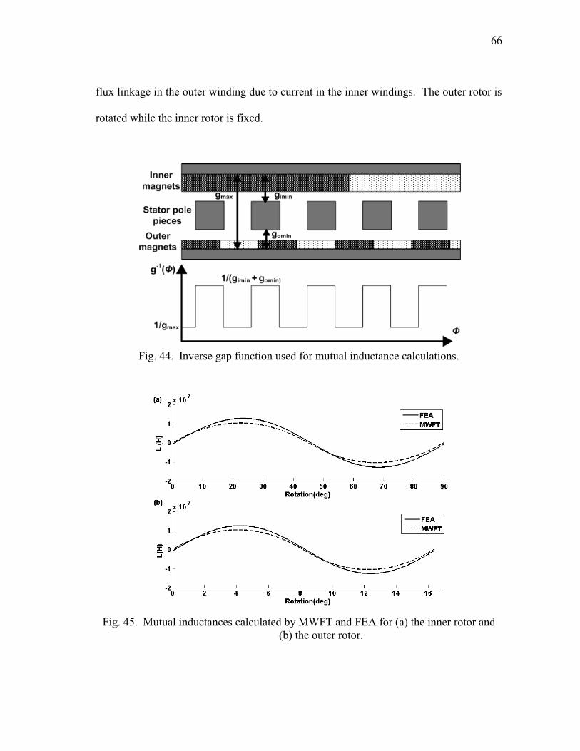
66
flux linkage in the outer winding due to current in the inner windings. The outer rotor is
rotated while the inner rotor is fixed.
Fig. 44. Inverse gap function used for mutual inductance calculations.
Fig. 45. Mutual inductances calculated by MWFT and FEA for (a) the inner rotor and
(b) the outer rotor.
67
As can be seen in the figures, the results for the mutual inductances agree very well,
with the differences in magnitude coming from a difference in the air gap with FEA
compared to MWFT.
III.2.5. Torque calculated from inductance
In finding the torque for the gear, FEA will once again be used as a basis for
comparison. In this section, the viability of replacing magnets with coils is investigated.
Fig. 46 shows the FEA calculated torque with an ideal magnetic gear built from
permanent magnets and with coils. The torque waveforms shown in Fig. 46 reveal an
operating point for the magnets which is less than the remanent magnetization used in
(35). The operating point for conventional permanent magnet machines is below the
remanent magnetization. This is due to the demagnetization from the stator field, as well
as the excitation requirement of the air gap [68]. This reduction however comes only due
to the excitation requirement for the air gap in the magnetic gear. Adjusting for the
operating point, the MMF for the magnets used in the inductance calculations is 2151
ampere-turns.
Torque is generated in the magnetic gear by the interaction of the magnetic rings
with each other and the stator pole pieces. This can be calculated by looking at the
changing reluctance in the gear, which is illustrated in Fig. 47. This changing reluctance,
, is represented in (44) and (45) as either unaligned, u, or aligned, a.
u
uu
A
l
0
(44)

68
a
aa
A
l
0
(45)
Fig. 46. Validity of replacing magnets with coils shown over a pole pair pitch showing
torque curves for the (a) outer rotor and (b) inner rotor.
Fig. 47. Changing reluctance as magnets move over pole pieces.
The changing reluctance translates into a change in inductance, and thus a change in
energy, as shown by the distinct energy values in (46) and (47). This is also known as
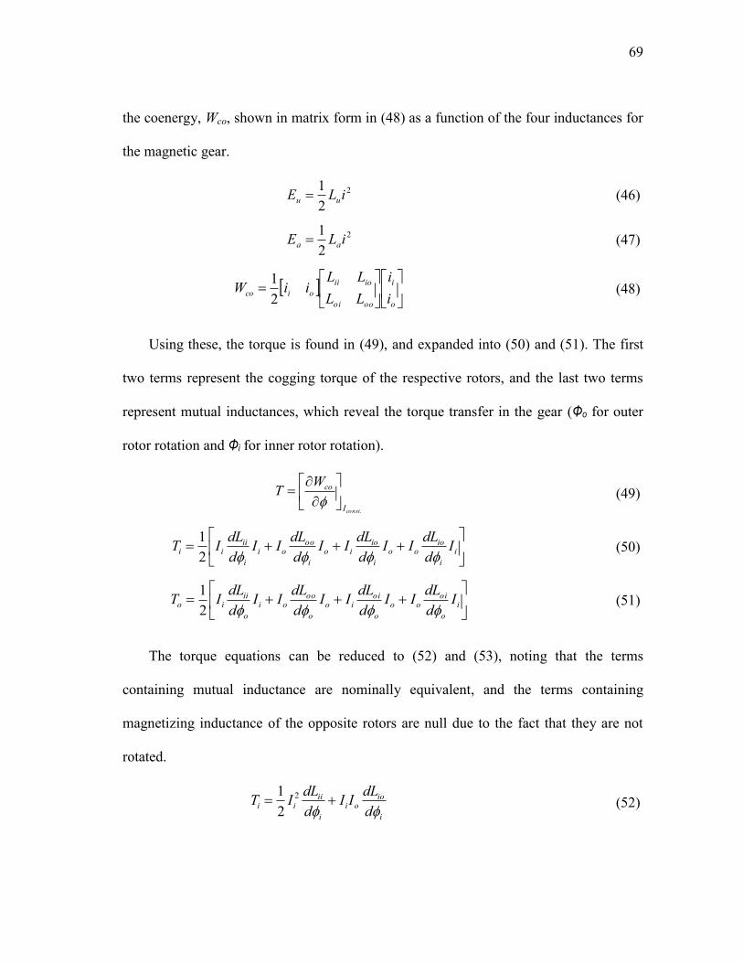
69
the coenergy, Wco, shown in matrix form in (48) as a function of the four inductances for
the magnetic gear.
2
2
1iLE uu
(46)
2
2
1iLE aa
(47)
o
i
oooi
ioii
oicoi
i
LL
LLiiW
2
1
(48)
Using these, the torque is found in (49), and expanded into (50) and (51). The first
two terms represent the cogging torque of the respective rotors, and the last two terms
represent mutual inductances, which reveal the torque transfer in the gear (Φo for outer
rotor rotation and Φi for inner rotor rotation).
.constI
coWT
(49)
i
i
iooo
i
ioio
i
oooi
i
iiii I
d
dLII
d
dLII
d
dLII
d
dLIT
2
1
(50)
i
o
oioo
o
oiio
o
oooi
o
iiio I
d
dLII
d
dLII
d
dLII
d
dLIT
2
1
(51)
The torque equations can be reduced to (52) and (53), noting that the terms
containing mutual inductance are nominally equivalent, and the terms containing
magnetizing inductance of the opposite rotors are null due to the fact that they are not
rotated.
i
iooi
i
iiii
d
dLII
d
dLIT
2
2
1
(52)

70
o
oiio
o
oooo
d
dLII
d
dLIT
2
2
1
(53)
Using (52) and the inductance calculated in Fig. 39, the torque of the inner rotor of
the magnetic coupling is shown in Fig. 48. The torque waveforms are in good
agreement, with the differences coming from the MMF taper between adjacent magnets
seen in the inductance calculations. The absence of the stator pole pieces in the magnetic
coupling yields a constant air gap, and thus no cogging torque.
Fig. 48. Torque of inner rotor of magnetic coupling calculated with FEA and MWFT.
As for the concentric planetary magnetic gear, the torques are calculated and shown
in Fig. 49, using the values of current adjusted for the operating point of the magnets.
The magnitude of the torque ripple on the inner and outer rotors is close to one another.
The frequency component of the torque ripple is also the same. The stall torque for the
outer rotor is 27 Nm with MWFT, compared to 29.5 Nm with FEA.
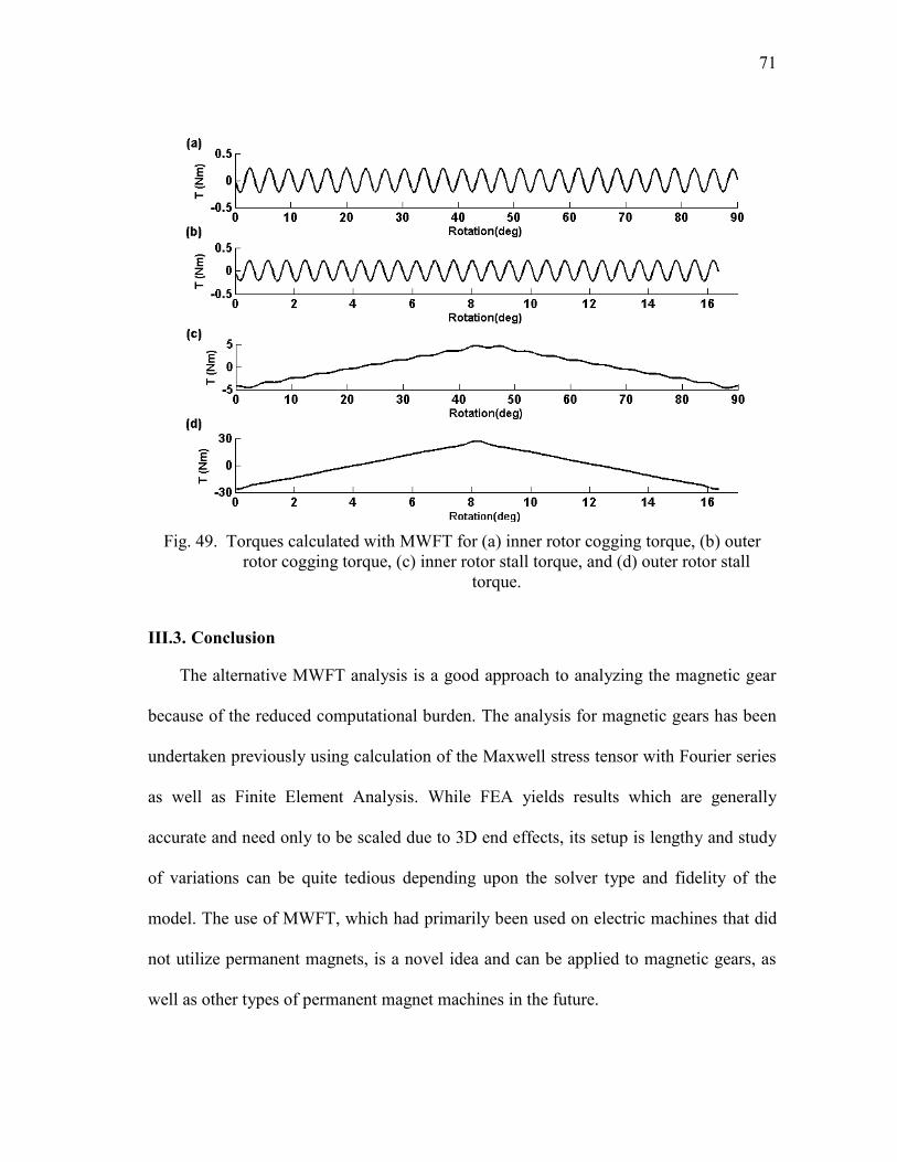
71
Fig. 49. Torques calculated with MWFT for (a) inner rotor cogging torque, (b) outer
rotor cogging torque, (c) inner rotor stall torque, and (d) outer rotor stall
torque.
III.3. Conclusion
The alternative MWFT analysis is a good approach to analyzing the magnetic gear
because of the reduced computational burden. The analysis for magnetic gears has been
undertaken previously using calculation of the Maxwell stress tensor with Fourier series
as well as Finite Element Analysis. While FEA yields results which are generally
accurate and need only to be scaled due to 3D end effects, its setup is lengthy and study
of variations can be quite tedious depending upon the solver type and fidelity of the
model. The use of MWFT, which had primarily been used on electric machines that did
not utilize permanent magnets, is a novel idea and can be applied to magnetic gears, as
well as other types of permanent magnet machines in the future.
72
IV. DAMPER WINDINGS FOR THE MAGNETIC GEAR
IV.1. The History of Damper Windings
The idea of damper windings is closely tied to synchronous generators. Damper, or
armotisseure, windings were added to the synchronous rotor in order to kill transient
oscillations caused by the load in [69]-[71]. More recently, damper windings have been
added to synchronous machines with permanent magnets [72]-[77]. These special types
of machines are referred to as line-start permanent magnet machines. The machine is
designed to start as an induction machine, i.e. as an asynchronous machine. The
permanent magnets actually detract from the performance of the machine during start-
up, since they provide a braking torque. Once the machine reaches synchronous speed,
the torque is provided by the permanent magnets and currents are no longer induced in
the rotor bars. In the case of a change in speed or load, current will be induced in the
rotor bars once again and arrest transient oscillations quicker than a conventional
permanent magnet machine. These types of machines have also been investigated for
their use in grid-connected synchronous generators [78][79].
It is here that the idea for adding damper windings to the magnetic gear is taken.
Magnetic gears, while enjoying multiple advantages over conventional mechanical
gears, are not as torsionally stiff [5]. Magnetic gears can be described by a stiffness
constant, K, measured in Nm/rad. This is equal to the slope of the stall torque curve for
the gear at the origin [66]. Gears undergoing changes in speed or load will experience
oscillations due to their relatively low stiffness, as shown in [6].
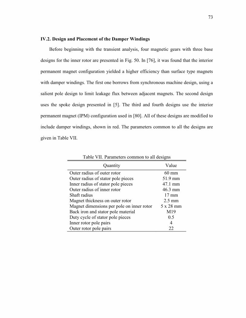
73
IV.2. Design and Placement of the Damper Windings
Before beginning with the transient analysis, four magnetic gears with three base
designs for the inner rotor are presented in Fig. 50. In [76], it was found that the interior
permanent magnet configuration yielded a higher efficiency than surface type magnets
with damper windings. The first one borrows from synchronous machine design, using a
salient pole design to limit leakage flux between adjacent magnets. The second design
uses the spoke design presented in [5]. The third and fourth designs use the interior
permanent magnet (IPM) configuration used in [80]. All of these designs are modified to
include damper windings, shown in red. The parameters common to all the designs are
given in Table VII.
Table VII. Parameters common to all designs
Quantity Value
Outer radius of outer rotor 60 mm
Outer radius of stator pole pieces 51.9 mm
Inner radius of stator pole pieces 47.1 mm
Outer radius of inner rotor
46.3 mm
Shaft radius 17 mm
Magnet thickness on outer rotor 2.5 mm
Magnet dimensions per pole on inner rotor 5 x 28 mm
Back iron and stator pole material M19
Duty cycle of stator pole pieces 0.5
Inner rotor pole pairs 4
Outer rotor pole pairs 22
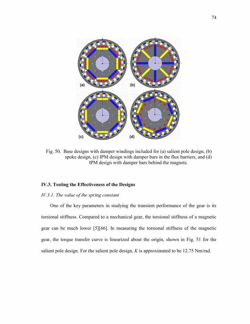
74
Fig. 50. Base designs with damper windings included for (a) salient pole design, (b)
spoke design, (c) IPM design with damper bars in the flux barriers, and (d)
IPM design with damper bars behind the magnets.
IV.3. Testing the Effectiveness of the Designs
IV.3.1. The value of the spring constant
One of the key parameters in studying the transient performance of the gear is its
torsional stiffness. Compared to a mechanical gear, the torsional stiffness of a magnetic
gear can be much lower [5][66]. In measuring the torsional stiffness of the magnetic
gear, the torque transfer curve is linearized about the origin, shown in Fig. 51 for the
salient pole design. For the salient pole design, K is approximated to be 12.75 Nm/rad.
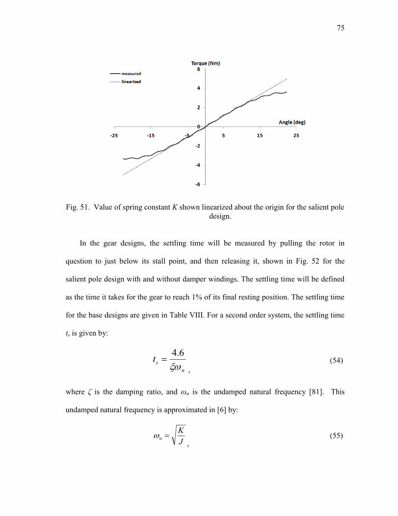
75
Fig. 51. Value of spring constant K shown linearized about the origin for the salient pole
design.
In the gear designs, the settling time will be measured by pulling the rotor in
question to just below its stall point, and then releasing it, shown in Fig. 52 for the
salient pole design with and without damper windings. The settling time will be defined
as the time it takes for the gear to reach 1% of its final resting position. The settling time
for the base designs are given in Table VIII. For a second order system, the settling time
ts is given by:
n
st
6.4
,
(54)
where δ is the damping ratio, and ωn is the undamped natural frequency [81]. This
undamped natural frequency is approximated in [6] by:
J
Kn
,
(55)
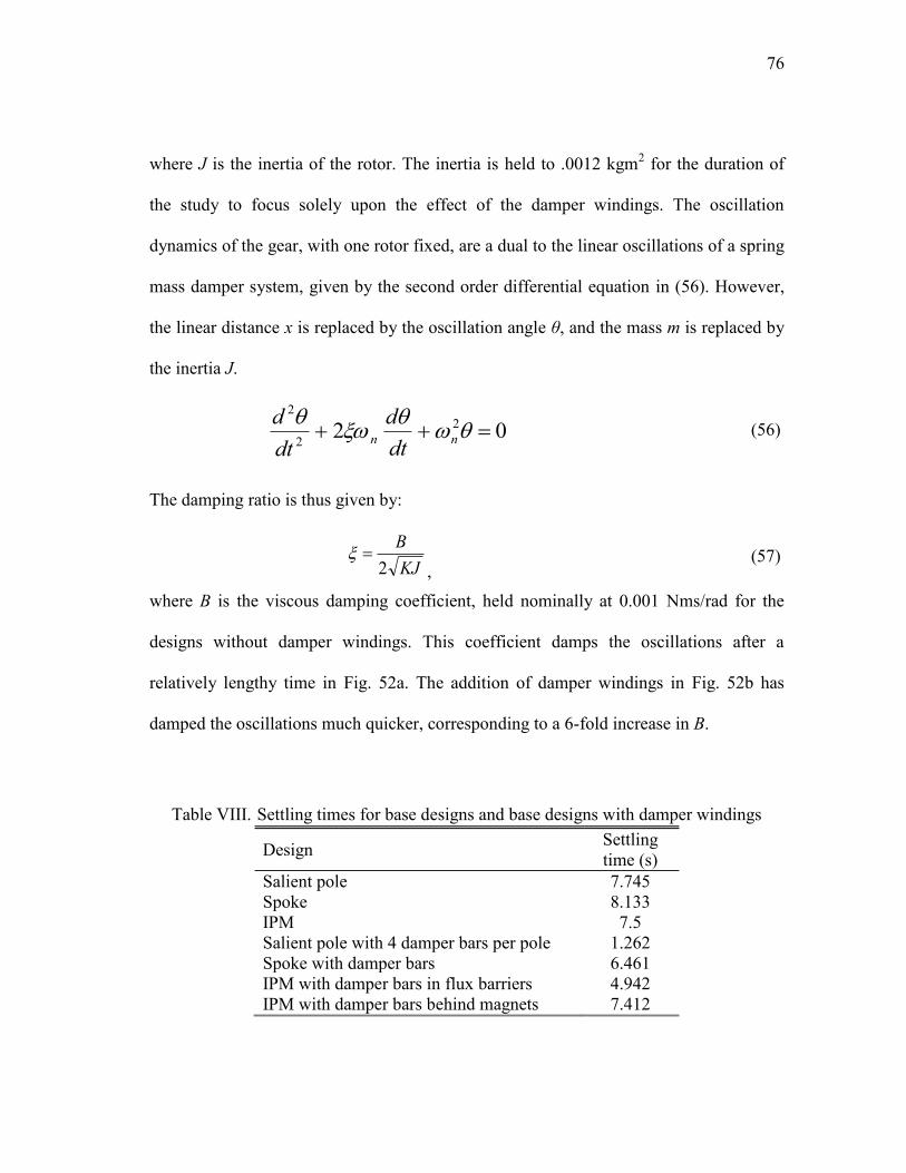
76
where J is the inertia of the rotor. The inertia is held to .0012 kgm2 for the duration of
the study to focus solely upon the effect of the damper windings. The oscillation
dynamics of the gear, with one rotor fixed, are a dual to the linear oscillations of a spring
mass damper system, given by the second order differential equation in (56). However,
the linear distance x is replaced by the oscillation angle θ, and the mass m is replaced by
the inertia J.
02 2
2
2
nndt
d
dt
d
(56)
The damping ratio is thus given by:
KJ
B
2
,
(57)
where B is the viscous damping coefficient, held nominally at 0.001 Nms/rad for the
designs without damper windings. This coefficient damps the oscillations after a
relatively lengthy time in Fig. 52a. The addition of damper windings in Fig. 52b has
damped the oscillations much quicker, corresponding to a 6-fold increase in B.
Table VIII. Settling times for base designs and base designs with damper windings
Design Settling
time (s)
Salient pole 7.745
Spoke 8.133
IPM 7.5
Salient pole with 4 damper bars per pole 1.262
Spoke with damper bars 6.461
IPM with damper bars in flux barriers 4.942
IPM with damper bars behind magnets 7.412
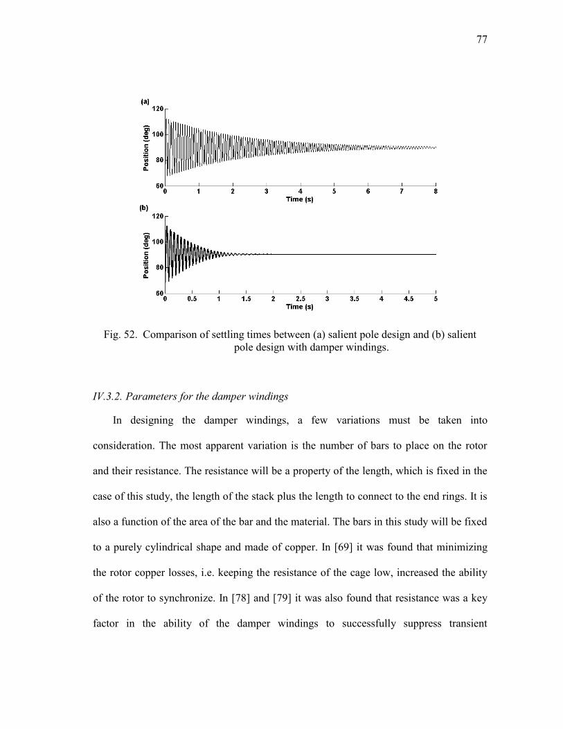
77
Fig. 52. Comparison of settling times between (a) salient pole design and (b) salient
pole design with damper windings.
IV.3.2. Parameters for the damper windings
In designing the damper windings, a few variations must be taken into
consideration. The most apparent variation is the number of bars to place on the rotor
and their resistance. The resistance will be a property of the length, which is fixed in the
case of this study, the length of the stack plus the length to connect to the end rings. It is
also a function of the area of the bar and the material. The bars in this study will be fixed
to a purely cylindrical shape and made of copper. In [69] it was found that minimizing
the rotor copper losses, i.e. keeping the resistance of the cage low, increased the ability
of the rotor to synchronize. In [78] and [79] it was also found that resistance was a key
factor in the ability of the damper windings to successfully suppress transient
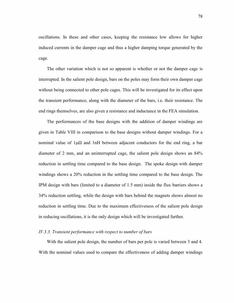
78
oscillations. In these and other cases, keeping the resistance low allows for higher
induced currents in the damper cage and thus a higher damping torque generated by the
cage.
The other variation which is not so apparent is whether or not the damper cage is
interrupted. In the salient pole design, bars on the poles may form their own damper cage
without being connected to other pole cages. This will be investigated for its effect upon
the transient performance, along with the diameter of the bars, i.e. their resistance. The
end rings themselves, are also given a resistance and inductance in the FEA simulation.
The performances of the base designs with the addition of damper windings are
given in Table VIII in comparison to the base designs without damper windings. For a
nominal value of 1µΩ and 1nH between adjacent conductors for the end ring, a bar
diameter of 2 mm, and an uninterrupted cage, the salient pole design shows an 84%
reduction in settling time compared to the base design. The spoke design with damper
windings shows a 20% reduction in the settling time compared to the base design. The
IPM design with bars (limited to a diameter of 1.5 mm) inside the flux barriers shows a
34% reduction settling, while the design with bars behind the magnets shows almost no
reduction in settling time. Due to the maximum effectiveness of the salient pole design
in reducing oscillations, it is the only design which will be investigated further.
IV.3.3. Transient performance with respect to number of bars
With the salient pole design, the number of bars per pole is varied between 3 and 4.
With the nominal values used to compare the effectiveness of adding damper windings
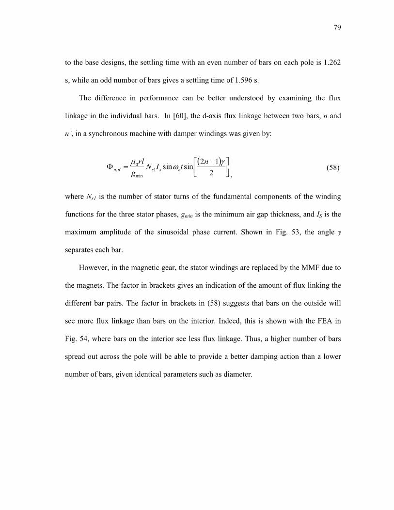
79
to the base designs, the settling time with an even number of bars on each pole is 1.262
s, while an odd number of bars gives a settling time of 1.596 s.
The difference in performance can be better understood by examining the flux
linkage in the individual bars. In [60], the d-axis flux linkage between two bars, n and
n’, in a synchronous machine with damper windings was given by:
2
12sinsin1
min
0',
ntIN
g
rlessnn
,
(58)
where Ns1 is the number of stator turns of the fundamental components of the winding
functions for the three stator phases, gmin is the minimum air gap thickness, and IS is the
maximum amplitude of the sinusoidal phase current. Shown in Fig. 53, the angle γ
separates each bar.
However, in the magnetic gear, the stator windings are replaced by the MMF due to
the magnets. The factor in brackets gives an indication of the amount of flux linking the
different bar pairs. The factor in brackets in (58) suggests that bars on the outside will
see more flux linkage than bars on the interior. Indeed, this is shown with the FEA in
Fig. 54, where bars on the interior see less flux linkage. Thus, a higher number of bars
spread out across the pole will be able to provide a better damping action than a lower
number of bars, given identical parameters such as diameter.
80
Fig. 53. Bar arrangement for 4 bars in one pole of the magnetic gear.
Fig. 54. Flux linkage in the salient pole design with 4 bars per pole as it settles to
equilibrium.
However, there remains a practical limit to the number of bars which can be placed
on each pole. In addition, the bars obstruct the path of the flux needed to provide useful
torque transfer for the magnetic gear, since the copper bars have a relative permeability
almost equal to air.
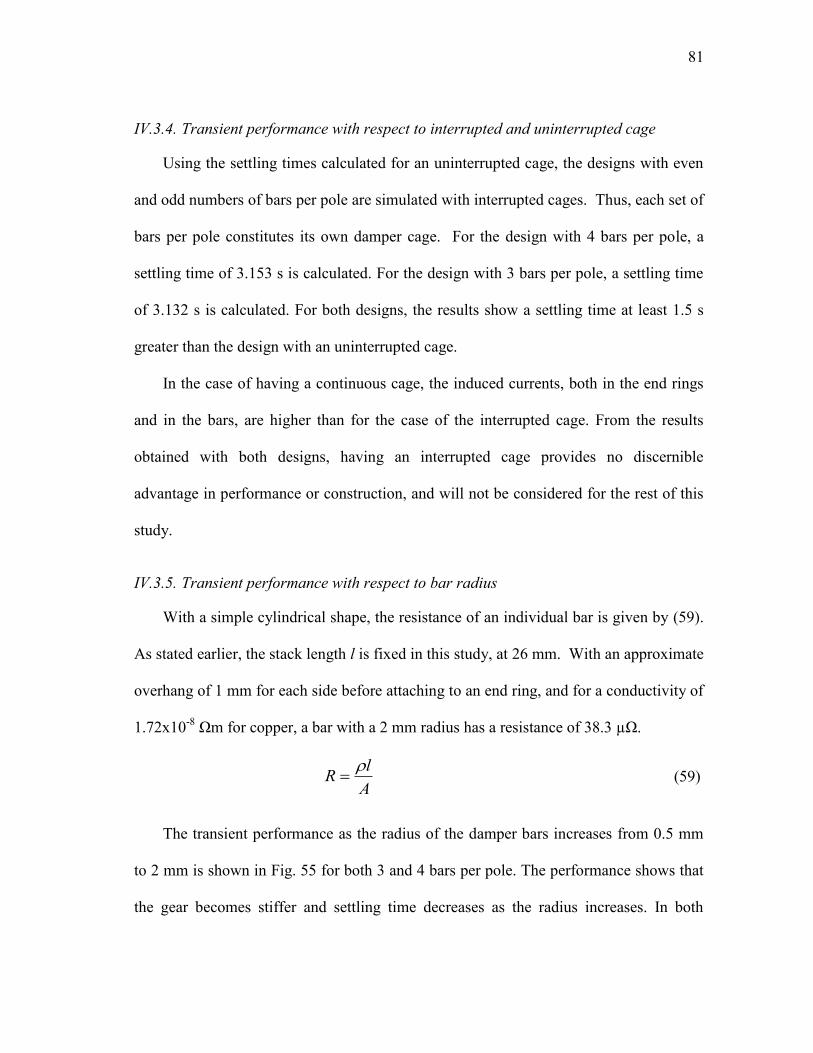
81
IV.3.4. Transient performance with respect to interrupted and uninterrupted cage
Using the settling times calculated for an uninterrupted cage, the designs with even
and odd numbers of bars per pole are simulated with interrupted cages. Thus, each set of
bars per pole constitutes its own damper cage. For the design with 4 bars per pole, a
settling time of 3.153 s is calculated. For the design with 3 bars per pole, a settling time
of 3.132 s is calculated. For both designs, the results show a settling time at least 1.5 s
greater than the design with an uninterrupted cage.
In the case of having a continuous cage, the induced currents, both in the end rings
and in the bars, are higher than for the case of the interrupted cage. From the results
obtained with both designs, having an interrupted cage provides no discernible
advantage in performance or construction, and will not be considered for the rest of this
study.
IV.3.5. Transient performance with respect to bar radius
With a simple cylindrical shape, the resistance of an individual bar is given by (59).
As stated earlier, the stack length l is fixed in this study, at 26 mm. With an approximate
overhang of 1 mm for each side before attaching to an end ring, and for a conductivity of
1.72x10⁻⁸
Ωm for copper, a bar with a 2 mm radius has a resistance of 38.3 µΩ.
A
lR
(59)
The transient performance as the radius of the damper bars increases from 0.5 mm
to 2 mm is shown in Fig. 55 for both 3 and 4 bars per pole. The performance shows that
the gear becomes stiffer and settling time decreases as the radius increases. In both

82
designs, a practical limit is reached around the maximum of 2 mm. As with the number
of bars, the radius of each bar also obstructs the path of the useful flux needed for the
magnetic gear.
Fig. 55. Effect of damper bar radius on settling time.
IV.3.6. Transient performance with respect to end ring resistance
As the radius of the damper bars changes the resistance, so can the thickness of the
end rings also change the resistance between adjacent conductors. A nominal value of 1
µΩ has been used thus far. For the case of 4 bars per pole, with an end ring that has a
radial thickness of 8 mm, and an average length of 8.3 mm between adjacent conductors,
this would dictate an end ring which has an approximate 17 mm axial thickness. The end
ring resistance is varied from 1 to 10 µΩ, corresponding to a thickness of 17 to 1.5 mm.
The settling time is shown for the designs with 3 and 4 bars per pole in Fig. 56. It is clear
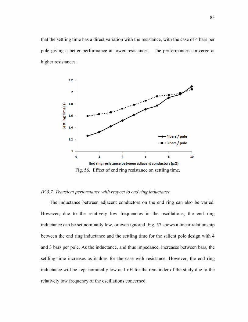
83
that the settling time has a direct variation with the resistance, with the case of 4 bars per
pole giving a better performance at lower resistances. The performances converge at
higher resistances.
Fig. 56. Effect of end ring resistance on settling time.
IV.3.7. Transient performance with respect to end ring inductance
The inductance between adjacent conductors on the end ring can also be varied.
However, due to the relatively low frequencies in the oscillations, the end ring
inductance can be set nominally low, or even ignored. Fig. 57 shows a linear relationship
between the end ring inductance and the settling time for the salient pole design with 4
and 3 bars per pole. As the inductance, and thus impedance, increases between bars, the
settling time increases as it does for the case with resistance. However, the end ring
inductance will be kept nominally low at 1 nH for the remainder of the study due to the
relatively low frequency of the oscillations concerned.

84
Fig. 57. Effect of end ring inductance on settling time.
IV.4. A Final Design
IV.4.1. Final design parameters
The design using the IPM layout and the salient barriers between adjacent magnets
is adopted for the final design, shown in Fig. 58, due to its effectiveness in damping
oscillations. The torque density of the gear will be effected by the distance the magnets
on the inner rotor are inset. The nominal distance without damper bars for rmag is 43.3
mm. This distance can be offset by up to 4 mm, moving the magnets closer to the shaft
to allow room for the damper bars. The effect upon stall torque for the outer rotor is
shown in Fig. 59, showing a linear drop with respect to the offset distance due to the
added MMF drop in the silicon steel of the rotor yoke.
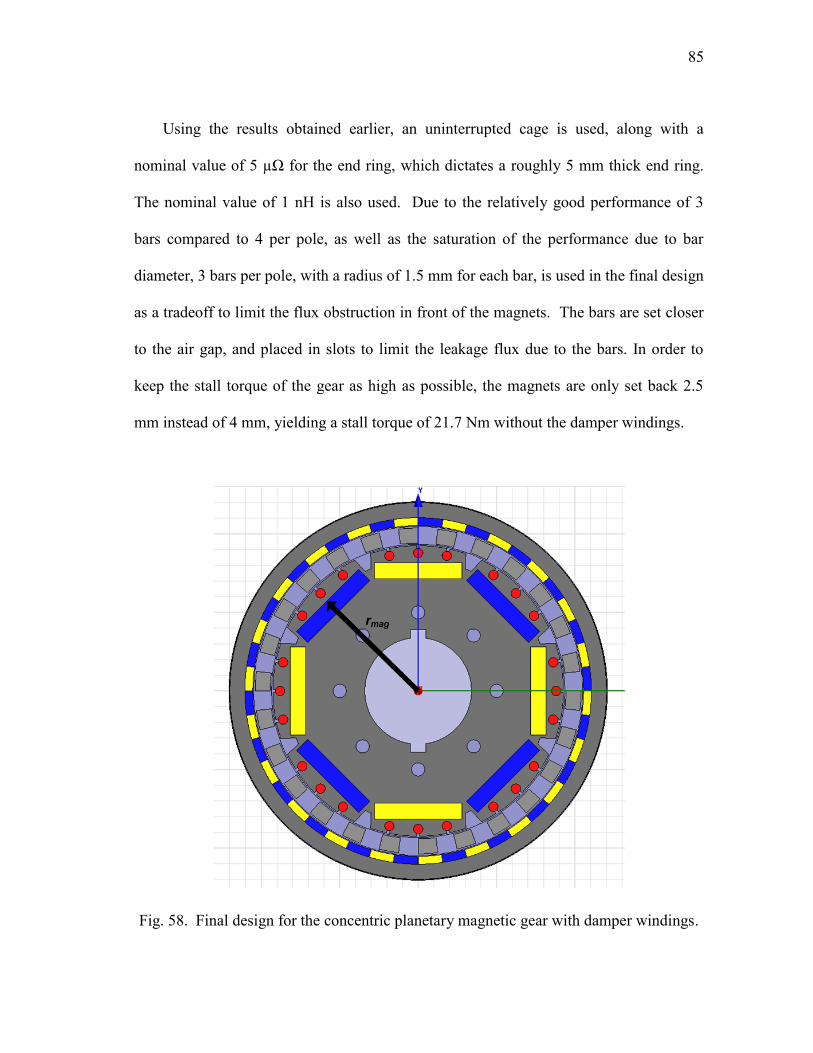
85
Using the results obtained earlier, an uninterrupted cage is used, along with a
nominal value of 5 µΩ for the end ring, which dictates a roughly 5 mm thick end ring.
The nominal value of 1 nH is also used. Due to the relatively good performance of 3
bars compared to 4 per pole, as well as the saturation of the performance due to bar
diameter, 3 bars per pole, with a radius of 1.5 mm for each bar, is used in the final design
as a tradeoff to limit the flux obstruction in front of the magnets. The bars are set closer
to the air gap, and placed in slots to limit the leakage flux due to the bars. In order to
keep the stall torque of the gear as high as possible, the magnets are only set back 2.5
mm instead of 4 mm, yielding a stall torque of 21.7 Nm without the damper windings.
Fig. 58. Final design for the concentric planetary magnetic gear with damper windings.
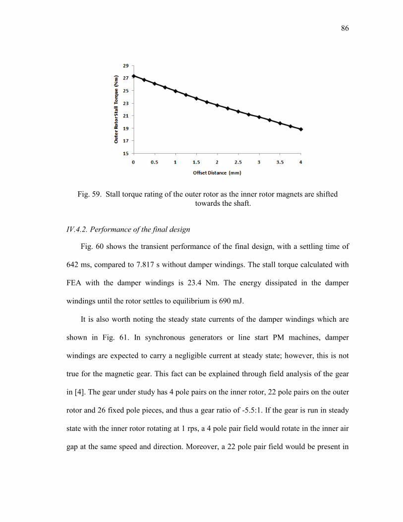
86
Fig. 59. Stall torque rating of the outer rotor as the inner rotor magnets are shifted
towards the shaft.
IV.4.2. Performance of the final design
Fig. 60 shows the transient performance of the final design, with a settling time of
642 ms, compared to 7.817 s without damper windings. The stall torque calculated with
FEA with the damper windings is 23.4 Nm. The energy dissipated in the damper
windings until the rotor settles to equilibrium is 690 mJ.
It is also worth noting the steady state currents of the damper windings which are
shown in Fig. 61. In synchronous generators or line start PM machines, damper
windings are expected to carry a negligible current at steady state; however, this is not
true for the magnetic gear. This fact can be explained through field analysis of the gear
in [4]. The gear under study has 4 pole pairs on the inner rotor, 22 pole pairs on the outer
rotor and 26 fixed pole pieces, and thus a gear ratio of -5.5:1. If the gear is run in steady
state with the inner rotor rotating at 1 rps, a 4 pole pair field would rotate in the inner air
gap at the same speed and direction. Moreover, a 22 pole pair field would be present in
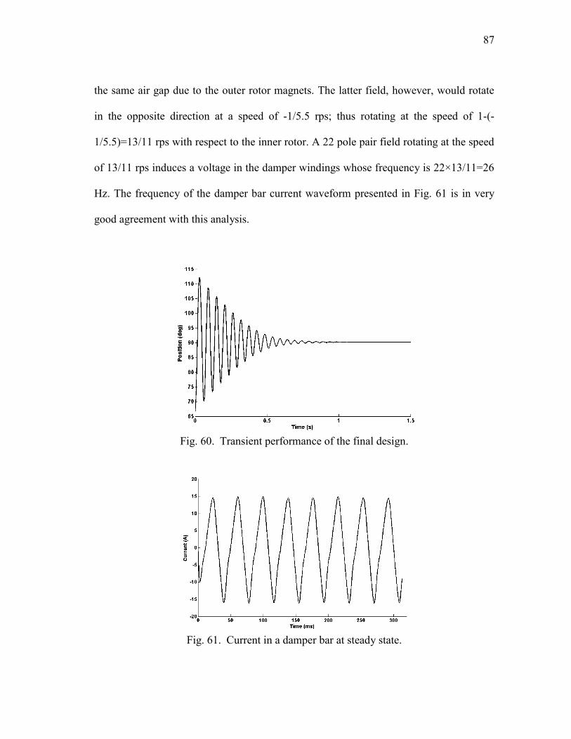
87
the same air gap due to the outer rotor magnets. The latter field, however, would rotate
in the opposite direction at a speed of -1/5.5 rps; thus rotating at the speed of 1-(-
1/5.5)=13/11 rps with respect to the inner rotor. A 22 pole pair field rotating at the speed
of 13/11 rps induces a voltage in the damper windings whose frequency is 22×13/11=26
Hz. The frequency of the damper bar current waveform presented in Fig. 61 is in very
good agreement with this analysis.
Fig. 60. Transient performance of the final design.
Fig. 61. Current in a damper bar at steady state.
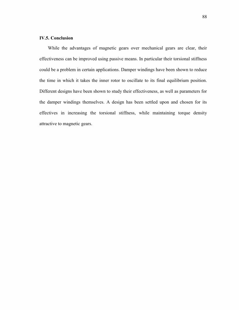
88
IV.5. Conclusion
While the advantages of magnetic gears over mechanical gears are clear, their
effectiveness can be improved using passive means. In particular their torsional stiffness
could be a problem in certain applications. Damper windings have been shown to reduce
the time in which it takes the inner rotor to oscillate to its final equilibrium position.
Different designs have been shown to study their effectiveness, as well as parameters for
the damper windings themselves. A design has been settled upon and chosen for its
effectives in increasing the torsional stiffness, while maintaining torque density
attractive to magnetic gears.

89
* V. THE PROTOTYPE
V.1. Background and Motivation
The prototype for this dissertation was begun in [5] at the Institute of Energy
Technology at Aalborg University. The original prototype was designed for a maximum
stall torque of 30 Nm and a stack length which could be supported with bearings from
mainly one side. Later, an additional bearing was added to support the inner rotor. The
magnetic forces tend to pull the rotors into the stator, causing the gear to grind to a halt.
This prototype was chosen for the envelope in which the variations presented below
could be studied. A magnetic gear designed from the ground up requires a considerable
amount of design and machine time. In addition, the cost to procure the magnets and cut
the laminations can be considerable. In Table IX, a summary of the approximate costs
involved in building a magnetic gear prototype are given. The table presents a
conservative estimate for a construction which should be relatively “problem free.” That
is, it is assumed problems discussed later with regards to assembly are avoided with
sufficiently good design and mechanical experience. Problems encountered with
assembly can quickly escalate cost. The costs are based upon quotes received from
various sources, and a machinist‟s rate of $50/hour.
_____________
* © 2010 IEEE. Reprinted with permission from "Analysis of the concentric planetary
magnetic gear with strengthened stator and interior permanent magnet (IPM) inner
rotor" by N.W. Frank and H.A. Toliyat, in Proc. IEEE Energy Convers. Cong. Exp.
ECCE 2010, pp. 2977-2984. For more information go to http://thesis.tamu.edu
/forms/IEEE%20permission%20note.pdf/view.

90
Table IX. Cost for magnetic gear prototype
Item Cost (USD)
Magnets (Nd-Fe-B) 800
Lamination cutting 2000
Bearings 200
End caps, housing, bracket 500
Labor 2000
Total 5500
V.2. Design
The proposed gear, the parameters of which are given in Table X, has different
variations of the stator which can be fabricated. Shown in Fig. 62, three ways of
connecting the stator pieces are shown, with 0.3 mm bridges between them.
Table X. Magnetic gear dimensions
Parameter Value (mm)
Outer radius of outer rotor 60
Inner radius of outer rotor 52.7
Inner rotor radius 46.3
Inner radius of stator pole pieces 47.1
Outer radius of stator pole pieces 51.9
Stack length 26
Inner rotor magnet thickness 5
Outer rotor magnet thickness 2.5
These correspond to the smallest possible bridges which could be fabricated with an
electrostatic discharge machine (EDM). First looked at in [47], the effect of closing the
segments on the interior was found to have a 4% reduction in stall torque rating. These
variations will be studied initially to find if there is a greater cost to having bridges
adjacent to one rotor or another.

91
Fig. 62. New variations of the stator with arrows pointing to bridges connecting the
stator pieces on the (a) interior, (b) exterior, and (c) both sides.
In addition to a new stator arrangement, it is also possible to use interior permanent
magnet design tools used on synchronous machines for the magnetic gear. This has the
advantage of negating the use of a retaining can for surface mount magnets. This could
be used as an advantage for electromechanical systems which need to be run at higher
speeds as well. Shown in Fig. 63a, the configuration uses the same amount of magnetic
material used in [5]. The corresponding torque angle curves calculated with FEA are
given in Fig. 63b. Finite element analysis has been used to simulate the behavior of the
different magnetic gear variations. The results of the variations are presented in Table XI
for Maxwell and MagNet.
The results also show that connecting the stator pieces on the interior costs less in
stall torque rating than connecting them on the exterior, roughly 2% versus roughly 23%
respectively. The results also show a considerable drop in stall torque rating between
surface mount magnets and the IPM layout. The surface mount configuration however is
an ideal configuration which does not account for the retaining can. In [47], a 3 mm
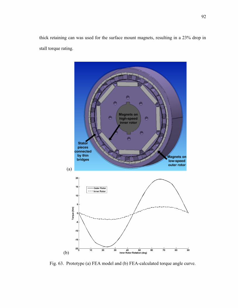
92
thick retaining can was used for the surface mount magnets, resulting in a 23% drop in
stall torque rating.
(a)
(b)
Fig. 63. Prototype (a) FEA model and (b) FEA-calculated torque angle curve.

93
Table XI. Stall torque rating for different FEA packages and variations of the stator
Variation Maxwell
Torque (Nm)
MagNet
Torque (Nm)
Surface mount magnets with pole
pieces
32.67 31.61
Interior magnets with pole pieces 24.49 25.95
Interior magnets with pole pieces
connected on interior
24.08
25.43
Interior magnets with pole pieces
connected on exterior
19.24 19.72
Interior magnets with pole pieces
connected on interior and exterior
18.85 19.33
Fig. 64 shows the results of changing the thickness of the bridges, when only one
side is taken into account. It is apparent that the bridges on the exterior detract from the
stall torque rating at a quicker rate than the addition of bridges on the interior. The
shorter span between adjacent poles on the outer rotor leads to more leakage flux paths
with the addition of the bridges. In terms of the magnetic flux path, it is ideal for the
bridges to be as thin as possible to achieve the highest stall torque rating for a given stack
length.
There is a trade-off for mechanical strength in the addition of the bridges. The
torsional twist angle exerted upon the stator, with a given torque, material, and stack
length, will only change with respect to the polar moment of inertia of any stator model.
In fact, the torsional twist angle, shown in (60) is inversely proportional to the polar
moment of inertia, which is the highest for the stator with bridges on both sides. Thus,
this model would result in the smallest twist angle for a given torque. Compared to this
model, there is a 4.8% decrease in the polar moment of inertia when bridges are only
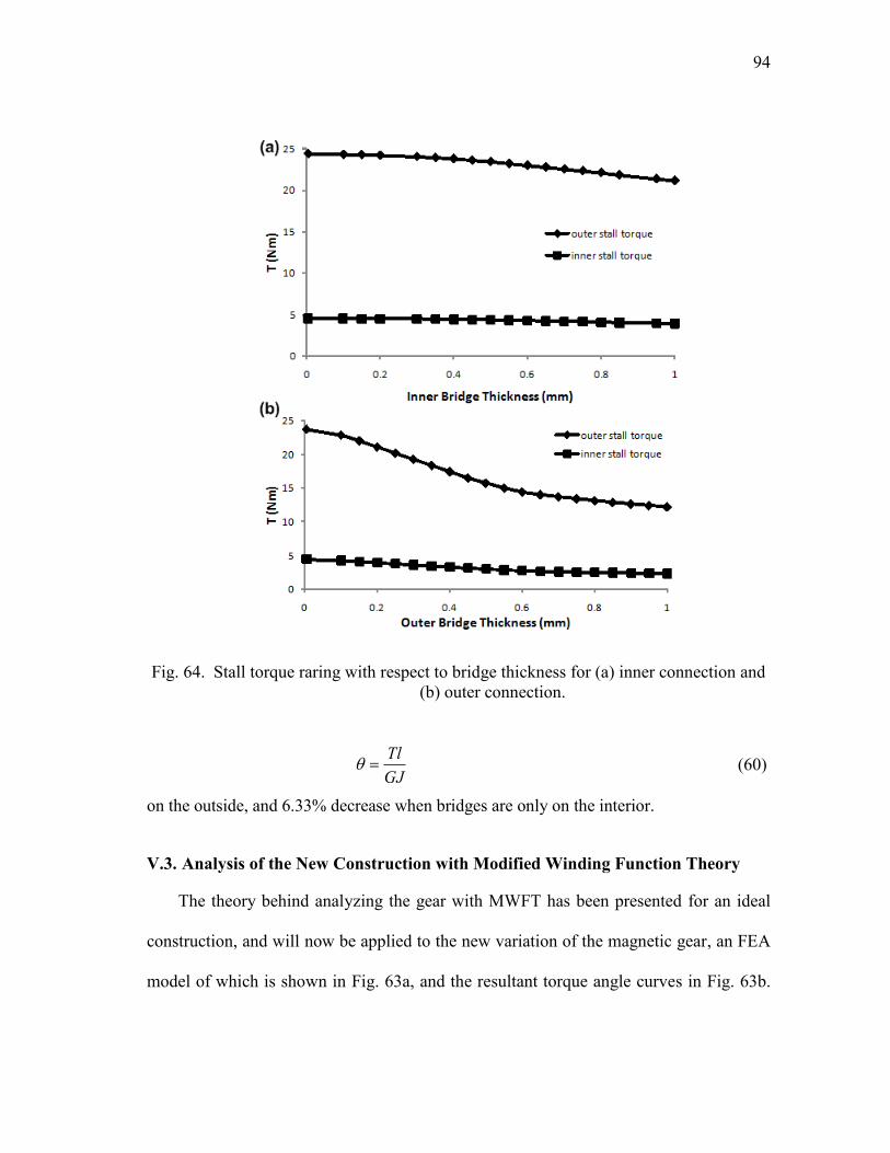
94
Fig. 64. Stall torque raring with respect to bridge thickness for (a) inner connection and
(b) outer connection.
GJ
Tl
(60)
on the outside, and 6.33% decrease when bridges are only on the interior.
V.3. Analysis of the New Construction with Modified Winding Function Theory
The theory behind analyzing the gear with MWFT has been presented for an ideal
construction, and will now be applied to the new variation of the magnetic gear, an FEA
model of which is shown in Fig. 63a, and the resultant torque angle curves in Fig. 63b.
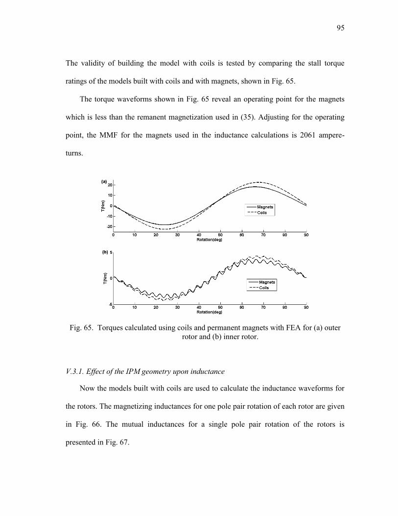
95
The validity of building the model with coils is tested by comparing the stall torque
ratings of the models built with coils and with magnets, shown in Fig. 65.
The torque waveforms shown in Fig. 65 reveal an operating point for the magnets
which is less than the remanent magnetization used in (35). Adjusting for the operating
point, the MMF for the magnets used in the inductance calculations is 2061 ampere-
turns.
Fig. 65. Torques calculated using coils and permanent magnets with FEA for (a) outer
rotor and (b) inner rotor.
V.3.1. Effect of the IPM geometry upon inductance
Now the models built with coils are used to calculate the inductance waveforms for
the rotors. The magnetizing inductances for one pole pair rotation of each rotor are given
in Fig. 66. The mutual inductances for a single pole pair rotation of the rotors is
presented in Fig. 67.
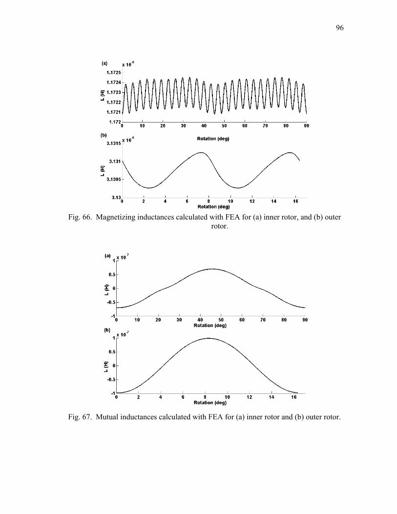
96
Fig. 66. Magnetizing inductances calculated with FEA for (a) inner rotor, and (b) outer
rotor.
Fig. 67. Mutual inductances calculated with FEA for (a) inner rotor and (b) outer rotor.
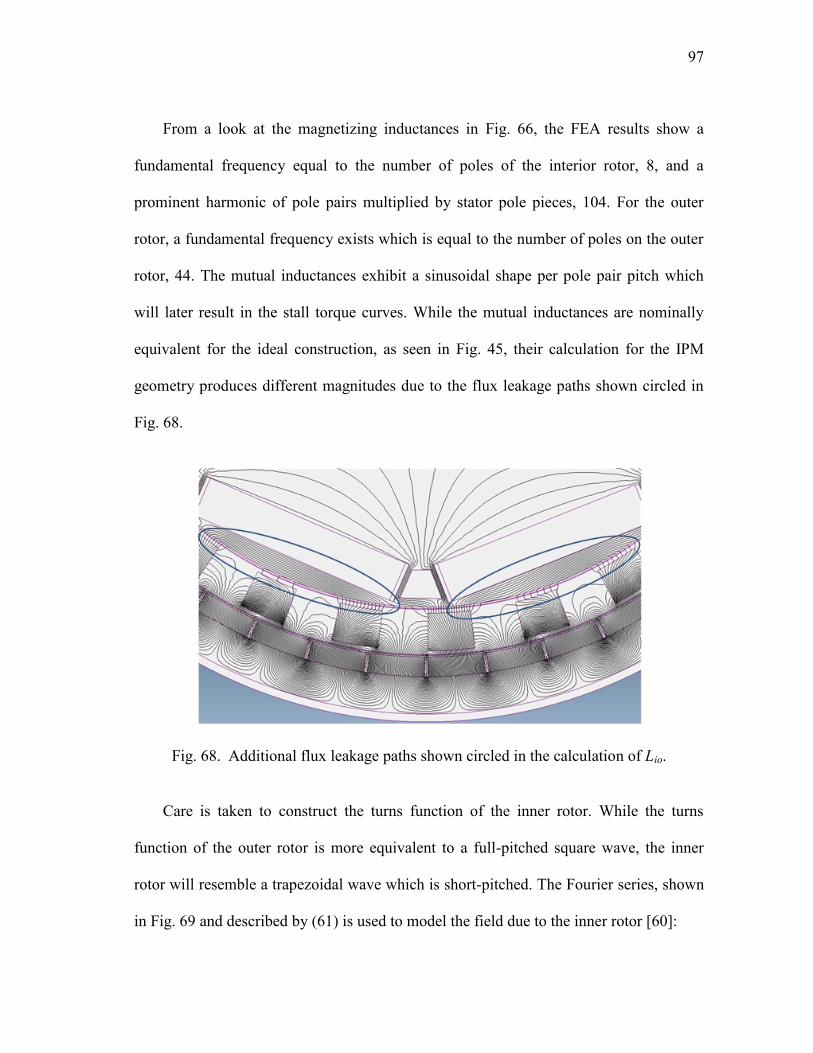
97
From a look at the magnetizing inductances in Fig. 66, the FEA results show a
fundamental frequency equal to the number of poles of the interior rotor, 8, and a
prominent harmonic of pole pairs multiplied by stator pole pieces, 104. For the outer
rotor, a fundamental frequency exists which is equal to the number of poles on the outer
rotor, 44. The mutual inductances exhibit a sinusoidal shape per pole pair pitch which
will later result in the stall torque curves. While the mutual inductances are nominally
equivalent for the ideal construction, as seen in Fig. 45, their calculation for the IPM
geometry produces different magnitudes due to the flux leakage paths shown circled in
Fig. 68.
Fig. 68. Additional flux leakage paths shown circled in the calculation of Lio.
Care is taken to construct the turns function of the inner rotor. While the turns
function of the outer rotor is more equivalent to a full-pitched square wave, the inner
rotor will resemble a trapezoidal wave which is short-pitched. The Fourier series, shown
in Fig. 69 and described by (61) is used to model the field due to the inner rotor [60]:

98
)cos(1
2cos
4
4sin
*2),(
,..5,3,1
hh
hh
h
NNn
h
,
(61)
where Φ is a phase shift which represents the rotation of the rotor and N is the number of
turns in a single coil, one in this case. The measure of how the MMF tapers off at the
magnet ends is given by β, 16.24° in this case. The short pitching between the magnets is
represented by ε, 28.76° in this case.
Fig. 69. Turns function for inner rotor.
The inductances are calculated using Matlab/Simulink, shown in Fig. 70 for the
magnetizing inductances and Fig. 71 for the mutual inductances. Over a pole pair pitch,
the magnetizing inductance calculated for the inner rotor has a fundamental harmonic
equal to the number of poles, 8. In addition, both inductances calculated with FEA and
MWFT show a prominent harmonic equal to the number of stator pole pieces multiplied
by the number of pole pairs, 104.
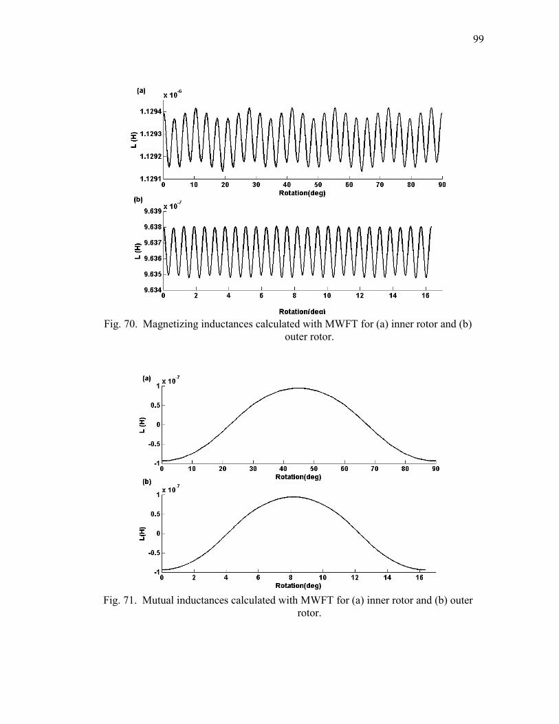
99
Fig. 70. Magnetizing inductances calculated with MWFT for (a) inner rotor and (b)
outer rotor.
Fig. 71. Mutual inductances calculated with MWFT for (a) inner rotor and (b) outer
rotor.
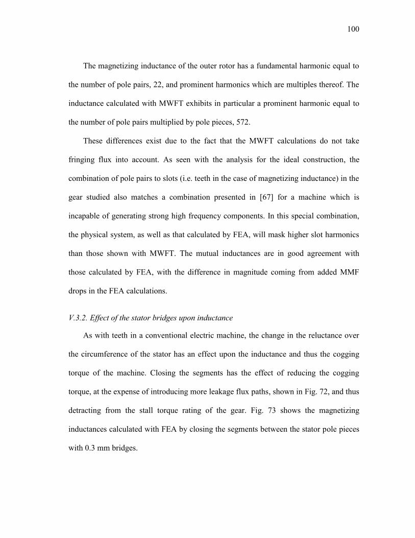
100
The magnetizing inductance of the outer rotor has a fundamental harmonic equal to
the number of pole pairs, 22, and prominent harmonics which are multiples thereof. The
inductance calculated with MWFT exhibits in particular a prominent harmonic equal to
the number of pole pairs multiplied by pole pieces, 572.
These differences exist due to the fact that the MWFT calculations do not take
fringing flux into account. As seen with the analysis for the ideal construction, the
combination of pole pairs to slots (i.e. teeth in the case of magnetizing inductance) in the
gear studied also matches a combination presented in [67] for a machine which is
incapable of generating strong high frequency components. In this special combination,
the physical system, as well as that calculated by FEA, will mask higher slot harmonics
than those shown with MWFT. The mutual inductances are in good agreement with
those calculated by FEA, with the difference in magnitude coming from added MMF
drops in the FEA calculations.
V.3.2. Effect of the stator bridges upon inductance
As with teeth in a conventional electric machine, the change in the reluctance over
the circumference of the stator has an effect upon the inductance and thus the cogging
torque of the machine. Closing the segments has the effect of reducing the cogging
torque, at the expense of introducing more leakage flux paths, shown in Fig. 72, and thus
detracting from the stall torque rating of the gear. Fig. 73 shows the magnetizing
inductances calculated with FEA by closing the segments between the stator pole pieces
with 0.3 mm bridges.
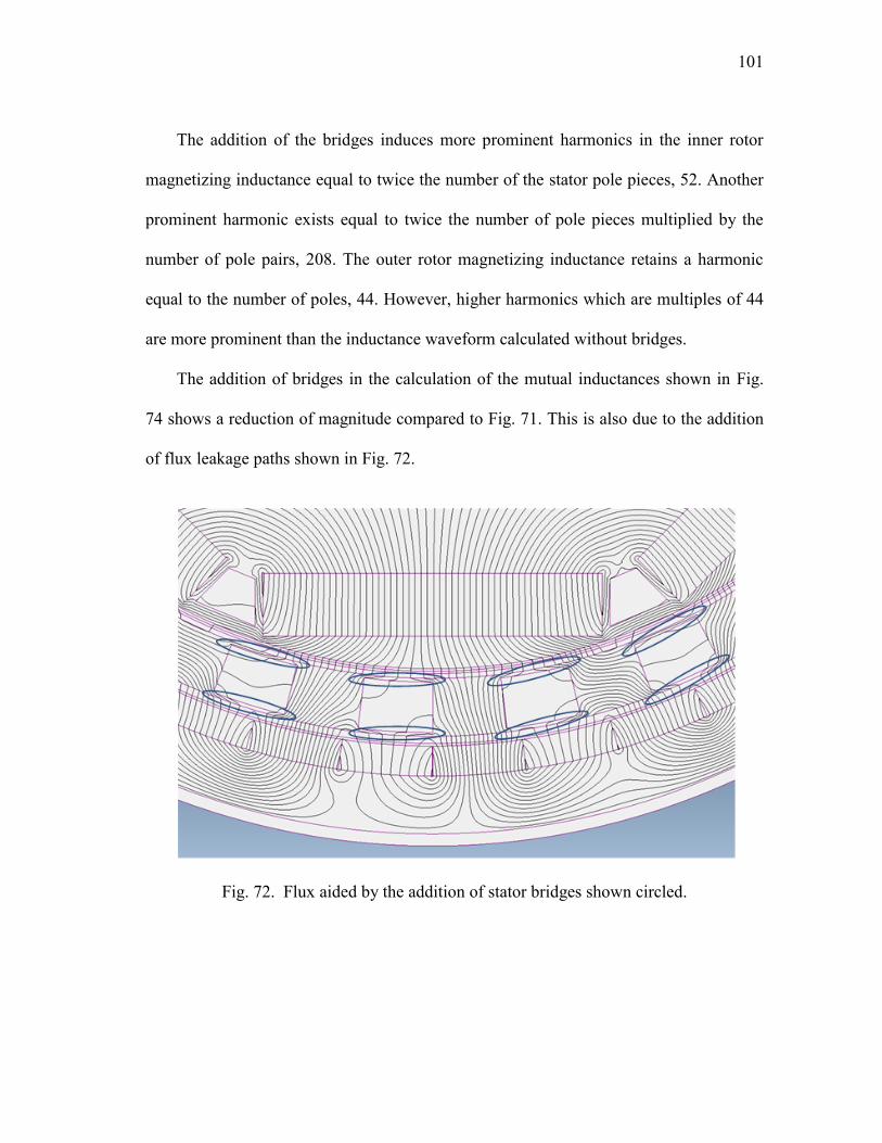
101
The addition of the bridges induces more prominent harmonics in the inner rotor
magnetizing inductance equal to twice the number of the stator pole pieces, 52. Another
prominent harmonic exists equal to twice the number of pole pieces multiplied by the
number of pole pairs, 208. The outer rotor magnetizing inductance retains a harmonic
equal to the number of poles, 44. However, higher harmonics which are multiples of 44
are more prominent than the inductance waveform calculated without bridges.
The addition of bridges in the calculation of the mutual inductances shown in Fig.
74 shows a reduction of magnitude compared to Fig. 71. This is also due to the addition
of flux leakage paths shown in Fig. 72.
Fig. 72. Flux aided by the addition of stator bridges shown circled.
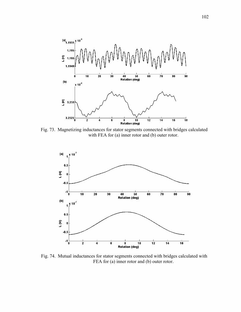
102
Fig. 73. Magnetizing inductances for stator segments connected with bridges calculated
with FEA for (a) inner rotor and (b) outer rotor.
Fig. 74. Mutual inductances for stator segments connected with bridges calculated with
FEA for (a) inner rotor and (b) outer rotor.

103
V.3.3. Torque output using MWFT
Using the inductances calculated with the IPM layout, and the MMF values adjusted
for the magnetic operating point, the torques are calculated using (52) and (53) and
shown in Fig. 75. The cogging torque shows an amplitude of ±0.098 Nm on the inner
rotor and ±0.19 Nm on the outer rotor. The stall torque for the outer rotor is 19.73 Nm
while the inner rotor is 3.71 Nm, providing a gearing ratio of 5.32:1.
By comparison, FEA gives a stall torque of approximately 19 Nm between the two
packages. The stall torque curves calculated by FEA are given in Fig. 63b. By contrast,
the steady state torque ripple calculated with FEA is given in Fig. 76. Neglecting offsets
which are present due to an operating point along the stall-torque curve which is near
zero, the dominant frequency for a rotation of one pole-pair is equivalent to that seen in
Fig. 75.
Fig. 75. Torques calculated with MWFT accounting for IPM geometry for (a) inner
rotor cogging torque, (b) outer rotor cogging torque, (c) inner rotor stall torque,
and (d) outer rotor stall torque.
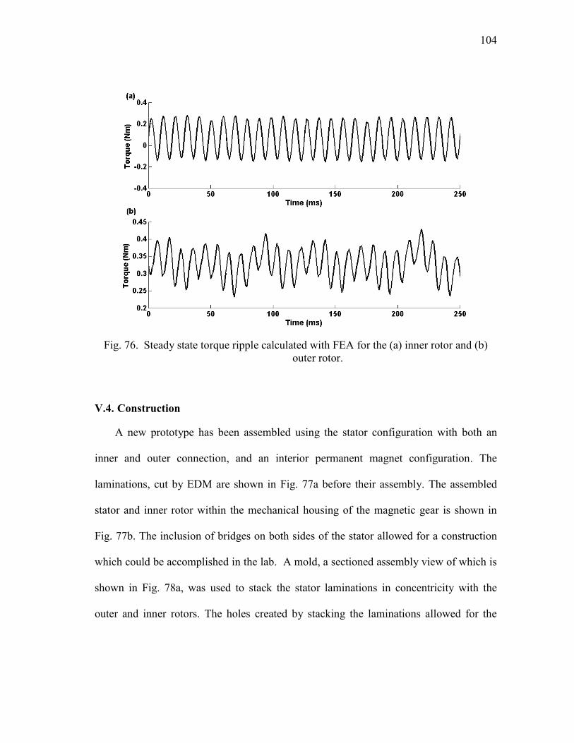
104
Fig. 76. Steady state torque ripple calculated with FEA for the (a) inner rotor and (b)
outer rotor.
V.4. Construction
A new prototype has been assembled using the stator configuration with both an
inner and outer connection, and an interior permanent magnet configuration. The
laminations, cut by EDM are shown in Fig. 77a before their assembly. The assembled
stator and inner rotor within the mechanical housing of the magnetic gear is shown in
Fig. 77b. The inclusion of bridges on both sides of the stator allowed for a construction
which could be accomplished in the lab. A mold, a sectioned assembly view of which is
shown in Fig. 78a, was used to stack the stator laminations in concentricity with the
outer and inner rotors. The holes created by stacking the laminations allowed for the
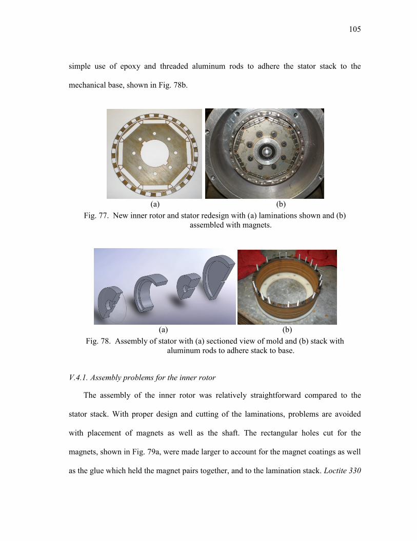
105
simple use of epoxy and threaded aluminum rods to adhere the stator stack to the
mechanical base, shown in Fig. 78b.
(a) (b)
Fig. 77. New inner rotor and stator redesign with (a) laminations shown and (b)
assembled with magnets.
(a) (b)
Fig. 78. Assembly of stator with (a) sectioned view of mold and (b) stack with
aluminum rods to adhere stack to base.
V.4.1. Assembly problems for the inner rotor
The assembly of the inner rotor was relatively straightforward compared to the
stator stack. With proper design and cutting of the laminations, problems are avoided
with placement of magnets as well as the shaft. The rectangular holes cut for the
magnets, shown in Fig. 79a, were made larger to account for the magnet coatings as well
as the glue which held the magnet pairs together, and to the lamination stack. Loctite 330
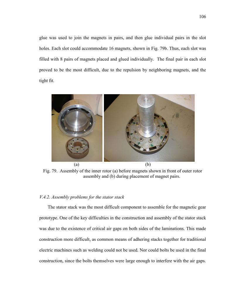
106
glue was used to join the magnets in pairs, and then glue individual pairs in the slot
holes. Each slot could accommodate 16 magnets, shown in Fig. 79b. Thus, each slot was
filled with 8 pairs of magnets placed and glued individually. The final pair in each slot
proved to be the most difficult, due to the repulsion by neighboring magnets, and the
tight fit.
(a) (b)
Fig. 79. Assembly of the inner rotor (a) before magnets shown in front of outer rotor
assembly and (b) during placement of magnet pairs.
V.4.2. Assembly problems for the stator stack
The stator stack was the most difficult component to assemble for the magnetic gear
prototype. One of the key difficulties in the construction and assembly of the stator stack
was due to the existence of critical air gaps on both sides of the laminations. This made
construction more difficult, as common means of adhering stacks together for traditional
electric machines such as welding could not be used. Nor could bolts be used in the final
construction, since the bolts themselves were large enough to interfere with the air gaps.
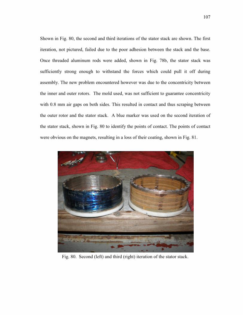
107
Shown in Fig. 80, the second and third iterations of the stator stack are shown. The first
iteration, not pictured, failed due to the poor adhesion between the stack and the base.
Once threaded aluminum rods were added, shown in Fig. 78b, the stator stack was
sufficiently strong enough to withstand the forces which could pull it off during
assembly. The new problem encountered however was due to the concentricity between
the inner and outer rotors. The mold used, was not sufficient to guarantee concentricity
with 0.8 mm air gaps on both sides. This resulted in contact and thus scraping between
the outer rotor and the stator stack. A blue marker was used on the second iteration of
the stator stack, shown in Fig. 80 to identify the points of contact. The points of contact
were obvious on the magnets, resulting in a loss of their coating, shown in Fig. 81.
Fig. 80. Second (left) and third (right) iteration of the stator stack.
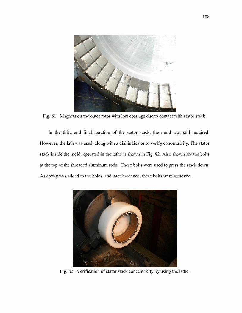
108
Fig. 81. Magnets on the outer rotor with lost coatings due to contact with stator stack.
In the third and final iteration of the stator stack, the mold was still required.
However, the lath was used, along with a dial indicator to verify concentricity. The stator
stack inside the mold, operated in the lathe is shown in Fig. 82. Also shown are the bolts
at the top of the threaded aluminum rods. These bolts were used to press the stack down.
As epoxy was added to the holes, and later hardened, these bolts were removed.
Fig. 82. Verification of stator stack concentricity by using the lathe.

109
V.5. Results
A dynamometer has been setup to test the gear, shown in Fig. 83. The high-torque
side of the gear is driven by an induction servo-motor. The low-torque side is loaded by
a hysteresis brake capable of stalling the gear. Each side of the gear has its own torque
transducer and encoder.
Fig. 83. Dynamometer for testing the magnetic gear prototype.
For the no-load test performed on the gear, Fig. 84 shows a 1.4 Nm peak-to-peak
torque ripple on the outer rotor and a 0.067 Nm peak-to-peak torque ripple on the inner
rotor. The load from the hysteresis brake is steadily increased to verify the stall torque of
the gear, shown in Fig. 85. The outer-rotor torque waveform shows the torque exerted on
the rotor increasing until 12.3 Nm, when the inner rotor stalls.
The stall torque of the new prototype corresponds well with that found in [5], 16
Nm. The new prototype, with 0.3 mm bridges on the inside and outside corresponds with

110
an approximate 23% reduction in stall torque. The new prototype also has a 0.1 mm
increase in the air gap on both sides as well to aid in assembly.
The stall torque for the new prototype has a torque density of approximately 42
Nm/l for the volume of the active components, compared with a calculated torque
density of 64 Nm/l with Maxwell and almost 66 Nm/l with MagNet. Thus the
constructed prototype yields 64-65% of the calculated torque density. This is in good
agreement with results obtained in [4] and [5] , with the reduction coming from end
effects of the magnets.
Fig. 84. Steady-state torque ripple of the gearbox under no load.
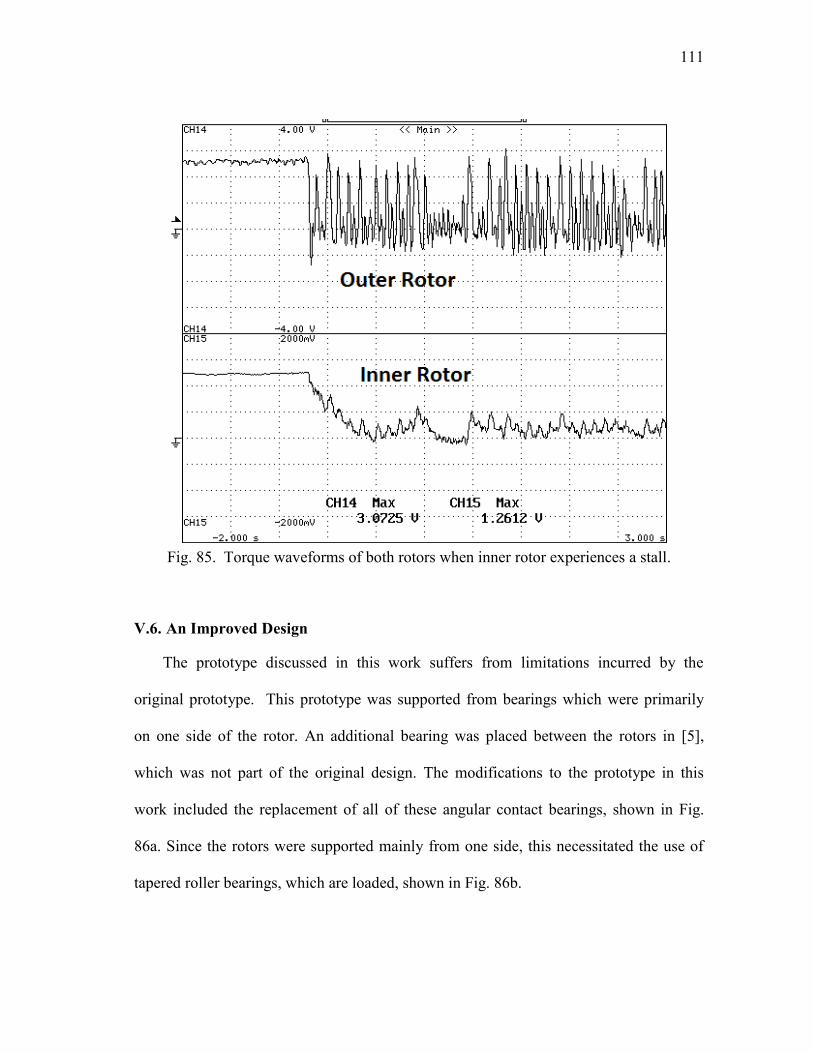
111
Fig. 85. Torque waveforms of both rotors when inner rotor experiences a stall.
V.6. An Improved Design
The prototype discussed in this work suffers from limitations incurred by the
original prototype. This prototype was supported from bearings which were primarily
on one side of the rotor. An additional bearing was placed between the rotors in [5],
which was not part of the original design. The modifications to the prototype in this
work included the replacement of all of these angular contact bearings, shown in Fig.
86a. Since the rotors were supported mainly from one side, this necessitated the use of
tapered roller bearings, which are loaded, shown in Fig. 86b.
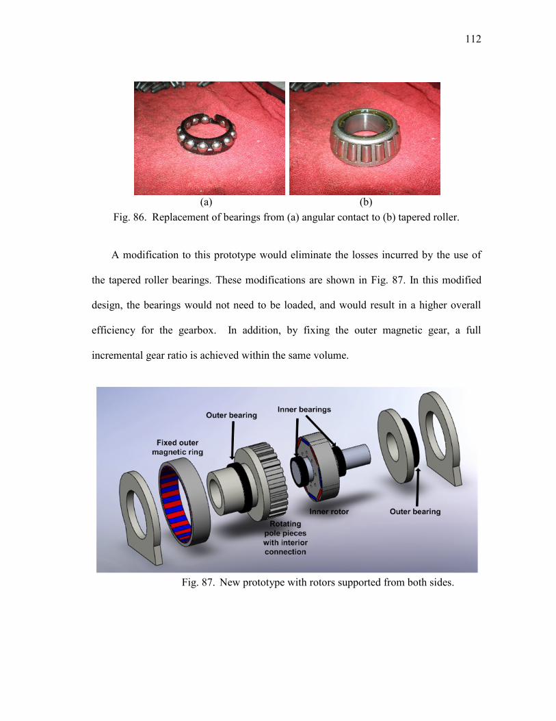
112
(a) (b)
Fig. 86. Replacement of bearings from (a) angular contact to (b) tapered roller.
A modification to this prototype would eliminate the losses incurred by the use of
the tapered roller bearings. These modifications are shown in Fig. 87. In this modified
design, the bearings would not need to be loaded, and would result in a higher overall
efficiency for the gearbox. In addition, by fixing the outer magnetic gear, a full
incremental gear ratio is achieved within the same volume.
Fig. 87. New prototype with rotors supported from both sides.

113
V.7. Conclusion
Different variations of the magnetic gear have been presented which could spur
more use by strengthening one of the key components of the gear, the stator pole pieces.
It has been shown that the stator is not only a critical component to the performance of
the gear, but also requires detailed analysis for any models to be accurate. Finite element
analysis, while useful and accepted, is tedious for testing different variations and
performing parametric studies of certain components of the gear. A new method of
analysis which uses winding function theory can run quicker and offer faster insight into
changing parameters of the gear. In the magnetic gear studied, it has been shown that
while using a more convenient stator segment construction and IPM layout, this also
comes at the expense of stall torque rating of the gear.
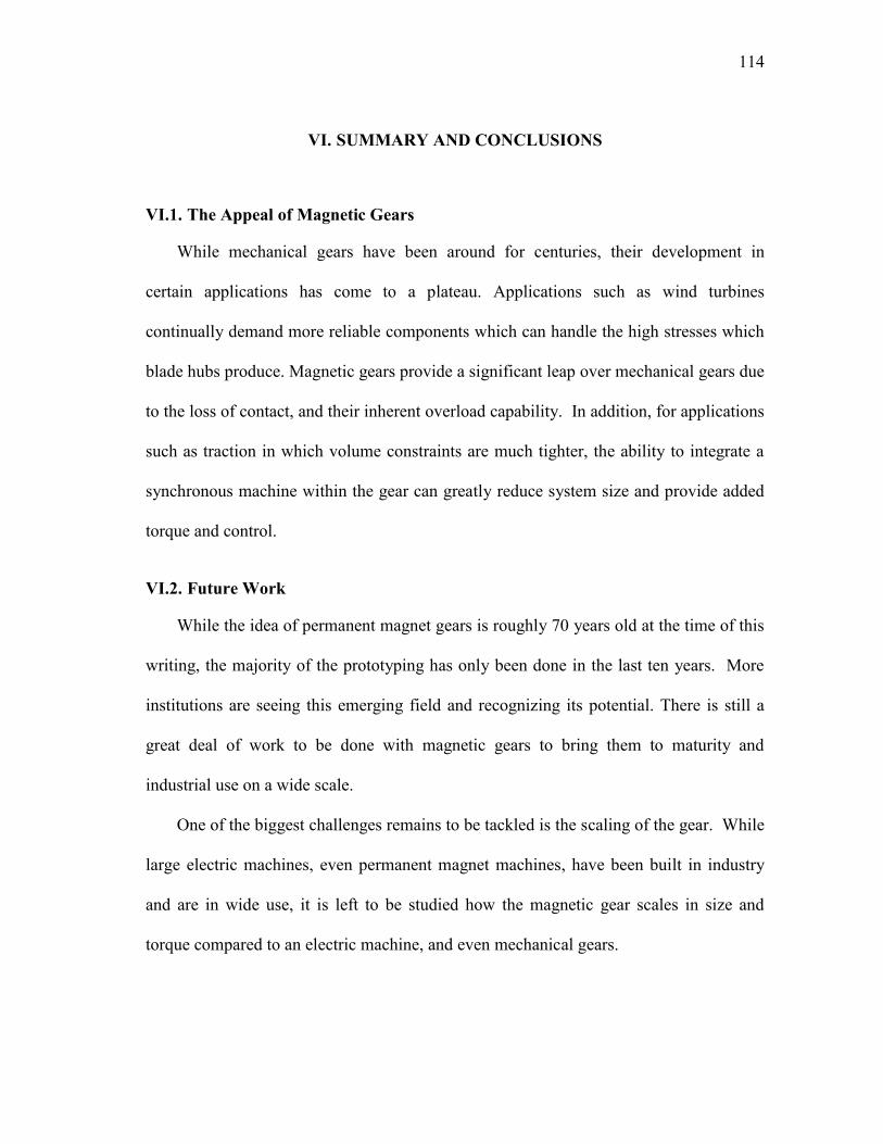
114
VI. SUMMARY AND CONCLUSIONS
VI.1. The Appeal of Magnetic Gears
While mechanical gears have been around for centuries, their development in
certain applications has come to a plateau. Applications such as wind turbines
continually demand more reliable components which can handle the high stresses which
blade hubs produce. Magnetic gears provide a significant leap over mechanical gears due
to the loss of contact, and their inherent overload capability. In addition, for applications
such as traction in which volume constraints are much tighter, the ability to integrate a
synchronous machine within the gear can greatly reduce system size and provide added
torque and control.
VI.2. Future Work
While the idea of permanent magnet gears is roughly 70 years old at the time of this
writing, the majority of the prototyping has only been done in the last ten years. More
institutions are seeing this emerging field and recognizing its potential. There is still a
great deal of work to be done with magnetic gears to bring them to maturity and
industrial use on a wide scale.
One of the biggest challenges remains to be tackled is the scaling of the gear. While
large electric machines, even permanent magnet machines, have been built in industry
and are in wide use, it is left to be studied how the magnetic gear scales in size and
torque compared to an electric machine, and even mechanical gears.
115
In addition, while the efficiencies which are calculated with magnetic gears are
comparable to mechanical gears, a study has yet to be done to accurately measure and
characterize core losses as well as eddy current losses in the coatings of the magnets in
magnetic gears which are run at high speed. While magnetic gears share the same
bearing losses as mechanical gears, they differ in these core losses.
New designs continue to emerge for magnetic gears which offer higher torque
densities and even variable gear ratio. There will undoubtedly be future work with
regards to new designs. However, the success of any new design will ultimately be
judged upon its ease of construction. New designs which offer good torque densities,
yet require exotic magnetic and bearing layouts could ultimately remain an academic
exercise while designs which are simpler to manufacture are slowly introduced into
industrial products.
With the increasing computational power of personal computers, the ability to tackle
3D FEA simulations is quickly becoming a new tool to machine designers. The end
effects mentioned in the 2D analysis of this dissertation detract a considerable amount of
the final stall torque of the prototype, depending upon stack length. Future work in
magnetic gears will undoubtedly benefit from 3D FEA, an example of which is shown in
Fig. 88 using MagNet‟s 3D static solver. The process is still slow compared to the 2D
solution and models must be made with fewer errors in order to converge upon a
solution. However, even the use of the static solver could help determine the correct
scaling factor for the 2D analysis to estimate a true stall torque for prototyping.
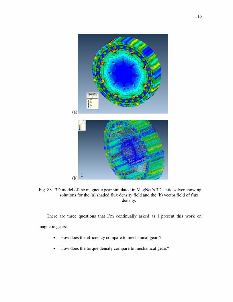
116
(a)
(b)
Fig. 88. 3D model of the magnetic gear simulated in MagNet‟s 3D static solver showing
solutions for the (a) shaded flux density field and the (b) vector field of flux
density.
There are three questions that I‟m continually asked as I present this work on
magnetic gears:
How does the efficiency compare to mechanical gears?
How does the torque density compare to mechanical gears?
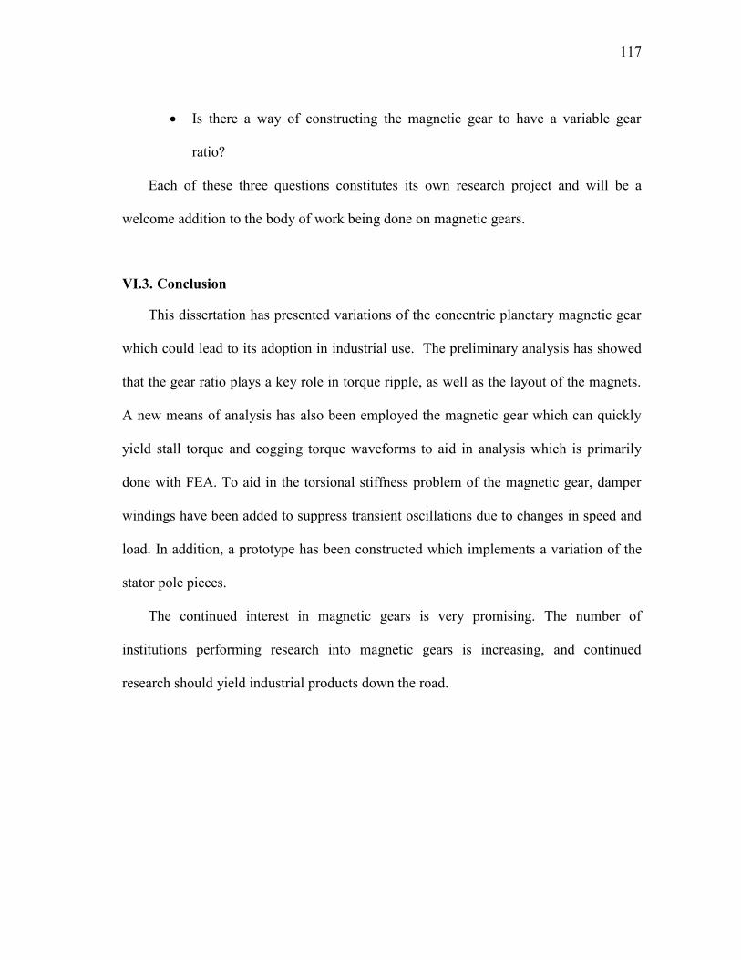
117
Is there a way of constructing the magnetic gear to have a variable gear
ratio?
Each of these three questions constitutes its own research project and will be a
welcome addition to the body of work being done on magnetic gears.
VI.3. Conclusion
This dissertation has presented variations of the concentric planetary magnetic gear
which could lead to its adoption in industrial use. The preliminary analysis has showed
that the gear ratio plays a key role in torque ripple, as well as the layout of the magnets.
A new means of analysis has also been employed the magnetic gear which can quickly
yield stall torque and cogging torque waveforms to aid in analysis which is primarily
done with FEA. To aid in the torsional stiffness problem of the magnetic gear, damper
windings have been added to suppress transient oscillations due to changes in speed and
load. In addition, a prototype has been constructed which implements a variation of the
stator pole pieces.
The continued interest in magnetic gears is very promising. The number of
institutions performing research into magnetic gears is increasing, and continued
research should yield industrial products down the road.

118
REFERENCES
[1] H.T. Faus, “Magnet gearing,” U.S. Patent 2,243,555, May 27, 1941.
[2] K. Tsurumoto and S. Kikuchi, “A new magnetic gear using permanent magnet,”
IEEE Tran. Magn., vol. 23, no. 5, pp. 3622-3624, Sept. 1987.
[3] K. Atallah and D. Howe, “A novel high-performance magnetic gear,” IEEE Trans.
Magn., vol. 37, no. 4, pp. 2844-2846, July 2001.
[4] K. Atallah, S. Calverley, and D. Howe, “Design, analysis and realisation of a high-
performance magnetic gear,” IEE Proc. Electr. Power Appl., vol. 151, no. 2, pp.
135-143, Mar. 2004.
[5] P. Rasmussen, T. Andersen, F. Jorgensen, and O. Nielsen, “Development of a high-
performance magnetic gear,” IEEE Trans. Ind. Appl., vol. 41, no. 3, pp. 764-770,
May/Jun. 2005.
[6] J. Wang and K. Atallah, “Modeling and control of „pseudo‟ direct-drive brushless
permanent magnet machines,” in Proc. IEEE Int. Conf. IEMDC 2009, Miami, FL,
pp. 870-875.
[7] L. Shah, A. Cruden, and B. W. Williams, “A magnetic gear box for application
with a contra-rotating tidal turbine,” in Proc. IEEE 7th Int. Conf. PEDS 2007,
Bangkok, Thailand, pp. 989-993.
[8] L. Jian, K.T. Chau, Y. Gong, J.Z. Jiang, C. Yu, and W. Li, “Comparison of coaxial
magnetic gears with different topologies,” IEEE Trans. Magn., vol. 45, no. 10, pp.
4526-4529, Oct. 2009.
[9] L. Yong, X. Jingwei, P. Kerong, and L. Yongping, “Principle and simulation
analysis of a novel structure magnetic gear,” in Proc. IEEE Int. Conf. ICEMS 2008,
Wuhan, China, pp. 3845-3849.
[10] C.C. Huang, M.C. Tsai, D.G. Dorrell, and B.J. Lin, “Development of a magnetic
planetary gearbox,” IEEE Trans. Magn., vol. 44, no. 3, pp. 403-412, Mar. 2008.
[11] F.T. Jorgensen, T.O. Andersen, and P.O. Rasmussen, “The cycloid permanent
magnetic gear,” IEEE Trans. Ind. Appl., vol. 44, no. 6, pp. 1659-1665, Nov./Dec.
2008.
119
[12] J. Rens, R. Clark, S. Calverley, K. Atallah, and D. Howe, “A novel magnetic
harmonic gear,” IEEE Trans. Ind. Appl., vol. 46, no. 1, pp. 206-212, Jan./Feb.
2010.
[13] R.J. Drago, Fundamentals of Gear Design, Boston, MA: Butterworths, 1988.
[14] J.E. Shigley, Mechanical Engineering Design, First Metric Edition, New York,
NY: McGraw-Hill, 1986.
[15] H.W. Mϋller, Epicyclic Drive Trains: Analysis, Synthesis, and Applications,
Detroit, MI: Wayne State University Press, 1982.
[16] F.L. Litvin and A. Fuentes, Gear Geometry and Applied Theory, Cambridge, U.K.:
Cambridge University Press, 2004.
[17] X. Luo, Y. Liao, H.A. Toliyat, A. El-Antably, and T. A. Lipo, “Multiple coupled
circuit modeling of induction machines,” IEEE Trans. Ind. Appl., vol. 31, no. 2, pp.
311-318, Mar./Apr. 1995.
[18] H.A. Toliyat, S.P. Waikar, and T.A. Lipo, “Analysis and simulation of five-phase
synchronous reluctance machines including third harmonic of airgap MMF,” IEEE
Trans. Ind. Appl., vol. 34, no. 2, pp. 332-339, Mar./Apr. 1998.
[19] W. Wang, K. Nam, and S. Kim, “Concentric winding BLDC motor design,” in
Proc. IEEE Int. Conf. IEMDC 2005, San Antonio, TX, pp. 157-161.
[20] B. Nikbakhtian. S. Talebi, P. Niazi, and H.A. Toliyat, “An analytical model for an
N-flux barrier per pole permanent magnet-assisted synchronous reluctance motor,”
in Proc. IEEE Int. Conf. IEMDC 2009, Miami, FL, pp. 129-136.
[21] R. Boyle, C. Greenwood, A. Hohler, M. Liebreich, V.S. O‟Brien, et. al., Global
trends in sustainable energy investment 2008: analysis of trends and issues in the
financing of renewable energy and energy efficiency, United Nations Environment
Programme and New Energy Finance Ltd., 2008 [Online]. Available: http://
www.unglobalcompact.org/docs/issues_doc/Environment/climate/Global_Trends
_2008.pdf, February 11, 2011.
[22] A. McCrone, E. Usher, V.S. O‟Brien, A. Hohler, R. Boyle, et. al., Global trends in
sustainable energy investment 2010: analysis of trends and issues in the financing
120
of renewable energy and energy efficiency, United Nations Environment
Programme and New Energy Finance Ltd., 2010 [Online]. Available:
http://bnef.com/Download/UserFiles_File_WhitePapers/sefi_unep_global_trends_2
010.pdf, February 11, 2011.
[23] E. Hau, Wind Turbines: Fundamentals, Technologies, Application, Economics,
Berlin, Germany: Springer, 2006.
[24] R. Harrison , E. Hau, and H. Snel, Large Wind Turbines: Design and Economics,
Chichester, U.K.: Wiley, 2000.
[25] E. Hau, J. Langenbrinck, Wega: Large Wind Turbines, Berlin, Germany: Springer,
1993.
[26] Capital Grant Scheme for Offshore Wind: Kentish Flats Offshore Wind Farm
Annual Report January 2006-December 2006 [Online]. Available: http://
www.berr.gov.uk/files/file41600.pdf, August 26, 2008.
[27] Capital Grant Scheme for Offshore Wind: Annual Report January 2005 –
December 2005 [Online]. Available: http://www.berr.gov.uk/files/file34791.pdf,
August 26, 2008.
[28] Capital Grant Scheme for the North Hoyle Offshore Wind Farm: Annual Report
July 2005 – June 2006 [Online]. Available: http://www.berr.gov.uk/files/
file41542.pdf, August 26, 2008.
[29] Capital Grant Scheme for Offshore Wind: Annual Report January 2006 –
December 2006 [Online]. Available: http://www.berr.gov.uk/files/file41543.pdf,
August 26, 2008.
[30] D. Robb, “Gearbox design for wind turbines improving but still face challenges,”
Windstats Newsletter, vol. 18, no. 3, pp. 6-8, Summer 2005.
[31] D. Robb and L. Harrison, “Who supplies to whom – wind industry gearboxes and
bearings,” Windpower Monthly, p. 56, Nov. 2005.
[32] L. Harrison, “Unacceptable wear found on gears,” Windpower Monthly, p. 24, Dec.
1998.
121
[33] D. Robb, “The role of bearings in gearbox failure,” Windpower Monthly, pp, 53-55,
57-58, Nov. 2005.
[34] G. Bohmeke, R. Boldt, and H. Beneke, “Direct drive, geared drive, intermediate
solutions – comparison of design features and operating economics,” European
Wind Energy Conference, Dublin, Ireland, Oct. 1997. pp. 664-667.
[35] S. Siegfriedsen and G. Bohmeke, “Multibrid technology – a significant step to
multi-megawatt wind turbines,” Wind Energy, vol. 1, no. 2, pp. 89-100, 1998.
[36] M. Benatmane, T. McCoy, T. Dalton, and T.L. Cooper, “Electric propulsion full
scale development on U.S. Navy surface ships,” Proc. Naval Symposium on
Electric Machines, 1998, pp. 125-134.
[37] P. Mongeau, “High torque density propulsion motors,” Naval Engineers Journal,
vol. 117, no. 4, pp. 53-57, Oct. 2005.
[38] B.W. Eckels and R.M. Calfo, “An evaluation of high torque density electric motor
topologies and their application for ship propulsion,” Proc. Naval Symposium on
Electric Machines, 2004.
[39] S. Sodhi, “Electromagnetic gearing applications in hybrid-electric vehicles,” M.S.
Thesis, Dept. Electrical Eng., Texas A&M University, College Station, TX, 1994.
[40] M. Ehsani, Y. Gao, S.E. Gay, and A. Emadi, Modern Electric, Hybrid Electric, and
Fuel Cell Vehicles, Boca Raton, FL: CRC Press, 2005.
[41] G.E. Weisenburger, “Electric motor,” U.S. Patent 667, 275, Feb. 1900.
[42] S.W. Moore and M. Ehsani, “A charge sustaining parallel HEV application of the
transmotor,” SAE International Congress and Exposition, Detroit, MI, 1999.
[43] Y. Gao and M. Ehsani, “A mild hybrid vehicle drive train with a floating stator
motor – configuration, control strategy, design and simulation verification,” SAE
Future Car Congress, Arlington, VA, 2002.
[44] K.T. Chau, D. Zhang, J.Z. Jiang, C. Liu, and Y. Zhang, “Design of a magnetic-
geared outer-rotor permanent-magnet brushless motor for electric vehicles,” IEEE
Trans. Magn., vol. 43, no. 6, pp. 2504-2506, Jun. 2007.
122
[45] L. Jian, K.T. Chau, and J.Z. Jiang, “An integrated magnetic-geared permanent-
magnet in-wheel motor drive for electric vehicles,” in Proc. IEEE Conf. VPPC
2008, Harbin, China, pp. 1-6.
[46] S. Du, Y. Zhang, and J. Jiang, “Research on a novel combined permanent magnet
electrical machine,” in Proc. IEEE Int. Conf. ICEMS 2008, Wuhan, China, pp.
3564-3567.
[47] P.O. Rasmussen, H.H. Mortensen, T.N. Matzen, T.M. Jahns, and H.A. Toliyat,
“Motor integrated permanent magnet gear with a wide torque-speed range,” in
Proc. IEEE Energy Convers. Cong. Exp. ECCE 2009, San Jose, CA, pp. 1510-
1518.
[48] Toyota Motor Sales “Toyota Camry Performance and Specs,” [Online]. Available:
http://www.toyota. com/camry/specs.html, March 15, 2010.
[49] L. Shah, A. Cruden, and B.W. Williams, “A variable speed magnetic gear box
using contra-rotating input shafts,” IEEE Trans. Magn., vol. 47, no. 2, pp. 431-438,
Feb. 2011.
[50] E. Gouda, S. Mezani, L. Baghli, and A. Rezzoug, “Comparative study between
mechanical and magnetic planetary gears,” IEEE Trans. Magn., vol. 47, no. 2, pp.
439-450, Feb. 2011.
[51] E.P. Furlani, R. Wang, and H. Kusnadi, “A three-dimensional model of computing
the torque of radial couplings,” IEEE Trans. Magn., vol. 31, no. 5, pp. 2522-2526,
Sep. 1995.
[52] Y.D. Yao, D.R. Huang, S.M. Lin, and S.J. Wang, “Theoretical computations of the
magnetic coupling between magnetic gears,” IEEE Trans. Magn., vol. 32, no. 3, pp.
710-713, May 1996.
[53] E.P. Furlani, “A two-dimensional analysis for the coupling of magnetic gears.”
IEEE Trans. Magn., vol. 33, no. 3, pp. 2317-2321, May 1997.
[54] F.T. Jorgensen, T.O. Andersen, and P.O. Rasmussen, “Two dimensional model of a
permanent magnet spur gear,” Proc. IEEE-IAS 2005, pp. 261-265.
123
[55] L. Jian and K.T. Chau, “Analytical calculation of magnetic field distribution in
coaxial magnetic gears,” Progress in Electromagnetics Research PIER 92, pp. 1-
16, 2009.
[56] T. Lubin, S. Mezani, and A. Rezzoug, “Exact analytical method for magnetic field
computation in the air gap of cylindrical electrical machines considering slotting
effects” IEEE Trans. Magn., vol. 46, no. 4, pp. 1092-1099, Apr. 2010.
[57] T. Lubin, S. Mezani, and A. Rezzoug, “Analytical computation of the magnetic
field distribution in a magnetic gear,” IEEE Trans. Magn., vol. 46, no. 7, pp. 2611-
2621, Jul. 2010.
[58] H.A. Toliyat and T.A. Lipo, “Transient analysis of cage induction machines under
stator, rotor bar and end ring faults,” IEEE Trans. Energy Convers., vol. 10, no. 2,
pp. 241-247, Jun. 1995.
[59] J.P. Johnson, A.V. Rajarathnam, H.A. Toliyat, S. Gopalakrishnan, and B. Fahimi,
“Torque optimization for a SRM using winding function theory with a gap-dividing
surface,” Proc. IEEE-IAS 1996, pp. 753-760.
[60] T.A. Lipo, Analysis of Synchronous Machines, Madison, WI: Wisconsin Power
Electronics Research Center, 2008.
[61] H.A. Toliyat, ECEN 611: General Theory of Electromechanical Motion Devices,
Class notes, Texas A&M University, College Station, TX, Spring 2005.
[62] N.A. Al-Nuaim and H.A. Toliyat, “A novel method for modeling dynamic air-gap
eccentricity in synchronous machines based on modified winding function theory,”
IEEE Trans. Energy Convers., vol. 13, no. 2, pp. 156-162, Jun. 1998.
[63] J. Faiz, M. Ojaghi, “Unified winding function approach for dynamic simulation of
different kinds of eccentricity faults in cage induction machines,” IET Electr.
Power Appl., vol. 3, no. 5, pp. 461-470, 2009.
[64] F.A. Fouad, T.W. Nehl, and N.A. Demerdash, “Magnetic field modeling of
permanent magnet type electronically operated synchronous machines using finite
elements,” IEEE Trans. Power App. Sys., vol. PAS-100, no. 9, pp. 4125-4135, Sep.
1981.
124
[65] F.A. Fouad, T.W. Nehl, and N.A. Demerdash, “Permanent magnet modeling for
use in vector potential finite element analysis in electrical machinery,” IEEE Trans.
Magn., vol. MAG-17, no. 6, pp. 3002-3004, Nov. 1981.
[66] R.G. Montague, C.M. Bingham, and K. Atallah, “Magnetic gear dynamics for
servo control,” in Proc. IEEE Conf. MELECON 2010, Valetta, Malta, pp. 1192-
1197.
[67] S. Nandi, S. Ahmed, and H.A. Toliyat, “Detection of rotor slot and other
eccentricity related harmonics in a three phase induction motor with different rotor
cages,” IEEE Trans. Energy Convers., vol. 16, no. 3, pp.253-260, Sep. 2001.
[68] R. Krishnan, Permanent Magnet Synchronous and Brushless DC Motor Drives,
Boca Raton, FL: CRC Press, Ch. 1, 2010.
[69] C.C. Shutt, “Some considerations in the design of damper windings for
synchronous motors,” Trans. AIEE, vol. 51, no. 2, pp. 424-430, Jan. 1932.
[70] J. Matsuki, T. Katagi, and T. Okada, “Damper windings phenomena of
synchronous machines during system oscillations,” IEEE Trans. Energy Convers.,
vol. 9, no. 2, pp. 376-382, Jun. 1994.
[71] J. Matsuki, T. Katagi, and T. Okada, “Slot ripples in the damper windings of a
salient-pole synchronous generator,” IEEE Trans. Energy Convers., vol. 9, no. 1,
pp. 126-134, Mar. 1994.
[72] N.A. Demerdash, T.M. Hijazi, and A.A. Arkadan, “Computation of winding
inductances of permanent magnet brushless DC motors with damper windings by
energy perturbation,” IEEE Trans. Energy Convers., vol. 3, no. 3, pp. 705-713,
Sep. 1988.
[73] T.M. Hijazi and N.A. Demerdash, “Impact of the addition of a rotor-mounted
damper bar cage on the performance of samarium-cobalt permanent magnets
brushless DC motor systems,” IEEE Trans. Energy Convers., vol. 3, no. 4, pp. 890-
898, Dec. 1988.
[74] T.J.E. Miller, M. Popescu, C. Cossar, M. McGilp, G. Strappazzon, N. Trivillin, and
R. Santarossa, “Line-start permanent-magnet motor single-phase steady-state

125
performance analysis,” IEEE Trans. Ind. Appl., vol. 40, no. 2, pp. 516-525,
Mar./Apr. 2004.
[75] G. Yang, J. Ma, J.X. Shen, and Y. Wang, “Optimal design and experimental
verification of a line-start permanent magnet synchronous motor,” in Proc. IEEE
Int. Conf. ICEMS 2008, Wuhan, China, pp. 3232-3236.
[76] P.W. Huang, S.H. Mao, M.C. Tsai, and C.T. Liu, “Investigation of line start
permanent magnet synchronous motors with interior-magnet rotors and surface-
magnet rotors,” in Proc. IEEE Int. Conf. ICEMS 2008, Wuhan, China, pp. 2888-
2893.
[77] B.L. Ahn, W.H. Kim, B.S. Kim, K.C. Ko, and J. Lee, “A study on the optimal
barrier design for high efficiency of LSPM,” in Proc. IEEE Int. Conf. ICEMS 2008,
Wuhan, China, pp. 3427-3429.
[78] J. Kinnunen, J. Pyrhonen, O.Liukkonen, and P. Kurronen, “Analysis of directly
network connected non-salient pole permanent magnet synchronous machines,” in
Proc. IEEE Int. Symp. Ind. Electr., Montreal, Canada, 2006, pp. 2217-2222.
[79] K. Kamiev, J. Nerg, and J. Pyrhonen, “Design of damper windings for direct-on-
line permanent magnet synchronous generators,” in Proc. IEEE Eurocon 2009,
Saint Petersburg, Russia, pp. 783-790.
[80] N.W. Frank and H.A. Toliyat, “Analysis of the concentric planetary magnetic gear
with strengthened stator and interior permanent magnet (IPM) inner rotor,” in Proc.
IEEE Energy Convers. Cong. Exp. ECCE 2010, Atlanta, GA, pp. 2977-2984.
[81] G.F. Franklin, J.D. Powell, and A. Emami-Naeini, Feedback Control of Dynamic
Systems, Upper Saddle River, NJ: Prentice Hall, 2002.
[82] C.G. Armstrong, “Power transmitting device,” U.S. Patent 687,292, Nov. 26, 1901.
[83] A.H. Neuland, “Apparatus for transmitting power,” U.S. Patent 1,171,351, Feb. 8,
1916.
[84] H.T. Faus, “Magnetic transmission,” U.S. Patent 2,371,511, March 13, 1945.
[85] G.A. Reese, “Magnetic gearing arrangement,” U.S. Patent 3,301,091, Jan. 31,
1967.
126
[86] T.B. Martin Jr., “Magnetic transmission,” U.S. Patent 3,378,710, April 16, 1968.
[87] H.P. Schlaeppi, “Magnetic gears,” U.S. Patent 3,382,386, May 7, 1968.
[88] N. Laing, “Centrifugal pump with magnetic drive,” U.S. Patent 3,762,839, Oct. 2,
1973.
[89] M. Hetzel, “Low friction miniature gear drive for transmitting small forces, and
method of making same,” U.S. Patent 3,792,578, Feb. 19, 1974.
[90] W.J. Mabe Jr., “Magnetic transmission,” U.S. Patent 5,013,949, May 7, 1991.
[91] J.E. Rode, “Magnetic gear and gear train configuration,” U.S. Patent 5,569,967,
Oct. 29, 1996.
[92] B. Ackermann and L. Honds, “Magnetic drive arrangement comprising a plurality
of magnetically cooperating parts which are movable relative to one another,” U.S.
Patent 5,633,555, May 27, 1997.
[93] B. Ackermann, “Magnetic drive arrangement,” U.S. Patent 5,994, 809, Nov. 30,
1999.
[94] E.W. Nissen, “Magnetic transmission,” U.S. Patent 7,105,968, Sep. 12, 2006.
[95] R.J. Wise, “Torque converter system and method of using the same,” U.S. Patent
7,145,276, Dec. 5, 2006.
[96] A.G. Razzell, and J.A. Cullen, “Compact electrical machine,” U.S. Patent
6,794,781
[97] W.J. McDonald, T.F. Price, and G.P. Hatch, “Wellbore motor having magnetic
gear drive,” U.S. Patent 7,481,283, Jan. 27, 2009.
[98] W.J. McDonald, T.F. Price, and G.P. Hatch, “Wellbore motor having magnetic
gear drive,” U.S. Patent 7,549,467, Jun. 23, 2009.

127
APPENDIX A
PATENTS RELATED TO MAGNETIC GEARING
A couple of patents precede Harold Faus‟ early patent on magnetic spur gears.
They were the first patents to employ gearing arrangements with electromagnetic means.
The first one, from 1901, is a spur gear arrangement with coils instead of permanent
magnets [82]. A patent followed 15 years later, employing electromagnetic means for a
planetary gearing arrangement very similar to the magnetic gear studied for this
dissertation [83]. The first patent related to a device which employed magnetic gearing
with only permanent magnets is found in [1]. Faus filed another patent shortly thereafter,
for a magnetic transmission capable of changing the gear ratio by means of a spiral gear
arrangement [84]. The next patent did not come until the latter half of the 1960‟s. This
patent described a magnetic planetary gear in which only one of the rotors employed
permanent magnets [85]. Two patents followed the next year relating to magnetic
planetary gearing arrangements [86][87]. In [88], a pump was assisted by means of a
planetary gearing arrangement similar to the gear studied in this dissertation. In [89], the
magnetic spur gear was once again patented. The magnetic dual to the mechanical
planetary gear was patented in 1991 [90]. The magnetic spur gear was once again
patented in 1996 [91].
The patent most directly related to the gear in this study was patented in 1997 [92].
The primary drawback to this arrangement was the geometry of the stator flux
modulator. The continuous nature allows for extensive flux leakage. An improvement to

128
the design followed later in [93], placing the stator flux modulator outside of the
magnetic rings. In [94], another magnetic transmission was patented, employing a
variable gear ratio by means of multiple spur gears. Yet another magnetic spur gear
arrangement followed shortly thereafter in [95].
In [96], the concentric planetary magnetic gear with an integrated motor was
patented and assigned to Rolls Royce. Two identical patents assigned to Dexter
Magnetic Technologies are the most recent patents at this time, relating to a magnetic
gear for wellbore drilling [97][98].

129
VITA
Nicolas Walter Frank received his B.S. degree (magna cum laude) in electrical
engineering from Texas A&M University in 2004, where he specialized in power
electronics. He also received his Ph.D. degree from Texas A&M University in 2011,
where he specialized in power electronics and electric machine design. In 2004 he
received a diversity fellowship from Texas A&M University to begin his graduate
studies.
During his time as a graduate student, he completed internships for the Air Force
Research Labs in Albuquerque, NM, United Technologies Research Center in East
Hartford, CT, Schlumberger in Sugar Land, TX, and was a guest researcher at the
Institute of Energy Technology at Aalborg University in Aalborg, Denmark. His time in
Denmark was funded in part by a grant from the American Scandinavian Foundation. He
is currently employed as an engineer at the ABB US Corporate Research Center in
Raleigh, NC. He can be reached through:
Attn.: Nicolas Frank
Texas A&M University ECE Dept.
214 Zachry Engineering Center
TAMU 3128
College Station, TX 77843-3128