Analysis of Stuck Pipe in Menengai - Stanford University€¦ · Awili 3 Immediate working/jarring...
12
PROCEEDINGS, Fourtieth Workshop on Geothermal Reservoir Engineering Stanford University, Stanford, California, January 26-28, 2015 SGP-TR-204 1 Analysis of Stuck Pipe Incidents in Menengai Billy Oketch Awili Geothermal Development Company-GDC, P.O. Box 17700-20100, Nakuru, KENYA [email protected]/[email protected] Keywords: stuck pipe, geothermal drilling, Menengai field, Kenya. ABSTRACT Stuck pipe or sticking and lost circulation are the two main events which cause Non-productive time (NPT) in the drilling industry. A considerable amount of time and resources can be spent in efforts to free a stuck pipe. Sometimes, stuck pipe events result in breakage (either intentional or non-intentional) of the drill string leading to a lot of money being spent in fishing. Unsuccessful fishing operations have resulted in costly alternatives including side-tracking or worse still, well abandonment. Stuck pipe situations are very common around the world with most data gathered in the petroleum drilling industry. A stuck pipe situation has led to abandonment of a well in the Menengai drilling field, Kenya as at the date of writing this paper. This paper explores the stuck pipe problem in geothermal well drilling. The paper presents causes of stuck pipe events, predicting their occurrence and common methods used to free stuck pipe. Finally an analysis is made of stuck pipe events in a few wells drilled in Menengai, Kenya using the graphical analysis software Easy View. The results will then be discussed to identify the causes of stuck pipe in Menengai. 1. INTRODUCTION The Geothermal Development Company is a Kenyan government owned entity that plans to develop 5,000 Megawatts of geothermal energy by 2030 in various fields in Kenya. Currently, production drilling is ongoing in Menengai high temperature field located in Nakuru within the central Kenyan rift. Menengai comprises the Menengai caldera, The Ol’rongai in the northwest and parts of Solai graben to the northeast. Drilling in this field has been quite difficult due to formation challenges that have subsequently caused stuck pipe incidences, among other non-productive activities. A stuck pipe situation occurs in drilling when the drill string cannot be reciprocated along or rotated about its axis while in the well. An analysis of drilling data has shown that on average, Menengai wells were stuck for six days (Okwiri, 2013) or 12% of total drilling time in Menengai (Makuk, 2013). The depth at around 2100 m (Rotary Kelly Bushing) has been identified as particularly troublesome leading to most of the stuck pipe incidences (Makuk, 2013). As of 1991, stuck pipe events were costing the drilling industry US$ 200 to 500 million annually and occurred in 15% of wells (Schlumberger, 1991). Sticking of the drill string is mostly viewed as an accident though methods have been used to predict such events. It is usually as a result of natural factors such as presence of permeable formations (which can easily cave and slough) or abnormally high pressured beds. Sticking can also be influenced by the degree of hole deflection and dogleg severity causing a keyhole. Drilling parameter changes can give hints to sticking problems that might occur later e.g. during tripping out. Bailey et al., demonstrated in the Schlumberger article (Stuck Pipe - Causes, Detection and Prevention, Schlumberger, 1991) how a water loss (from drilling mud) event during drilling later caused differential sticking during tripping out. The high costs associated with sticking form the justification for study of the causes of stuck pipe in Menengai, with a view of preventing them. Figure 1 shows the location of some of the wells drilled in Menengai. 2. CAUSES OF STUCK PIPE Pipe sticking Mechanism and Causes can be summarized in Table 1. TABLE 1: Pipe Sticking Mechanism & Causes (Rabia, 2001) Pipe Sticking Mechanisms and Causes Mechanism Differential Sticking Mechanical Sticking Cause Hole Pack Off Formation & BHA (Wellbore Geometry) Differential Force Settled Cuttings Key Seating Shale Instability Mobile Formations Fractured Rocks Under gauge Hole Cement Blocks Micro Doglegs and Ledges Junk Drilling Into Magma
Transcript of Analysis of Stuck Pipe in Menengai - Stanford University€¦ · Awili 3 Immediate working/jarring...

PROCEEDINGS, Fourtieth Workshop on Geothermal Reservoir Engineering
Stanford University, Stanford, California, January 26-28, 2015
SGP-TR-204
1
Analysis of Stuck Pipe Incidents in Menengai
Billy Oketch Awili
Geothermal Development Company-GDC, P.O. Box 17700-20100, Nakuru, KENYA
[email protected]/[email protected]
Keywords: stuck pipe, geothermal drilling, Menengai field, Kenya.
ABSTRACT
Stuck pipe or sticking and lost circulation are the two main events which cause Non-productive time (NPT) in the drilling industry. A
considerable amount of time and resources can be spent in efforts to free a stuck pipe. Sometimes, stuck pipe events result in breakage
(either intentional or non-intentional) of the drill string leading to a lot of money being spent in fishing. Unsuccessful fishing operations
have resulted in costly alternatives including side-tracking or worse still, well abandonment. Stuck pipe situations are very common
around the world with most data gathered in the petroleum drilling industry. A stuck pipe situation has led to abandonment of a well in
the Menengai drilling field, Kenya as at the date of writing this paper. This paper explores the stuck pipe problem in geothermal well
drilling. The paper presents causes of stuck pipe events, predicting their occurrence and common methods used to free stuck pipe.
Finally an analysis is made of stuck pipe events in a few wells drilled in Menengai, Kenya using the graphical analysis software Easy
View. The results will then be discussed to identify the causes of stuck pipe in Menengai.
1. INTRODUCTION
The Geothermal Development Company is a Kenyan government owned entity that plans to develop 5,000 Megawatts of geothermal
energy by 2030 in various fields in Kenya. Currently, production drilling is ongoing in Menengai high temperature field located in
Nakuru within the central Kenyan rift. Menengai comprises the Menengai caldera, The Ol’rongai in the northwest and parts of Solai
graben to the northeast. Drilling in this field has been quite difficult due to formation challenges that have subsequently caused stuck
pipe incidences, among other non-productive activities. A stuck pipe situation occurs in drilling when the drill string cannot be
reciprocated along or rotated about its axis while in the well. An analysis of drilling data has shown that on average, Menengai wells
were stuck for six days (Okwiri, 2013) or 12% of total drilling time in Menengai (Makuk, 2013). The depth at around 2100 m (Rotary
Kelly Bushing) has been identified as particularly troublesome leading to most of the stuck pipe incidences (Makuk, 2013). As of 1991,
stuck pipe events were costing the drilling industry US$ 200 to 500 million annually and occurred in 15% of wells (Schlumberger,
1991). Sticking of the drill string is mostly viewed as an accident though methods have been used to predict such events. It is usually
as a result of natural factors such as presence of permeable formations (which can easily cave and slough) or abnormally high pressured
beds. Sticking can also be influenced by the degree of hole deflection and dogleg severity causing a keyhole. Drilling parameter
changes can give hints to sticking problems that might occur later e.g. during tripping out. Bailey et al., demonstrated in the
Schlumberger article (Stuck Pipe - Causes, Detection and Prevention, Schlumberger, 1991) how a water loss (from drilling mud) event
during drilling later caused differential sticking during tripping out. The high costs associated with sticking form the justification for
study of the causes of stuck pipe in Menengai, with a view of preventing them. Figure 1 shows the location of some of the wells drilled
in Menengai.
2. CAUSES OF STUCK PIPE
Pipe sticking Mechanism and Causes can be summarized in Table 1.
TABLE 1: Pipe Sticking Mechanism & Causes (Rabia, 2001)
Pipe Sticking Mechanisms and Causes
Mechanism Differential Sticking Mechanical Sticking
Cause
Hole Pack Off Formation & BHA (Wellbore Geometry)
Differential Force
Settled Cuttings Key Seating
Shale Instability Mobile Formations
Fractured Rocks Under gauge Hole
Cement Blocks Micro Doglegs and Ledges
Junk Drilling Into Magma

Awili
2
Figure 1: Map Showing Menengai Field and Wells (GDC, 2013)
2.1 Differential Sticking
During drilling the drilling fluid pressure is maintained at a higher value compared to the reservoir or formation pressure. When a
permeable zone is reached, the difference in these pressures forces some of the fluid to seep into the permeable zone. As this happens,
the solids in the drilling fluid are filtered out at the hole wall forming a layer called a filter cake. If a substantial area of the string
surface comes into contact with the cake formed, then only the outer wall surface exposed to the drilling fluid “sees” the higher drilling
fluid pressure and the contact surface to the cake “sees” the lower formation pressure. This pressure difference pushes the pipe to stick
to hole wall and embed itself further into the filter cake with a great force (can reach more than a million pounds force). The string thus
gets differentially stuck and force required to pull it exceeds the yield point of the pipe. The signs of differential sticking are:
1. The pipe can neither be moved up and down nor rotated;
2. Circulation is unaffected.
The differential sticking force depends on the pressure differential and the area of contact with the porous formation zone among other
factors
Differential sticking may be prevented by:
Maintaining lowest continuous fluid loss;
Keeping circulating mud free of drilled solids;
Keeping a very low differential pressure with allowance for swab and surge;
Using a mud system that yields smooth mud cake (low friction co-efficient);
Maintaining drill string rotation at all times;
Using grooved or spiral drill collars;
Minimizing length of drill collars and Bottom Hole Assembly (BHA).
If differential sticking occurs, the following solutions are mostly used:

Awili
3
Immediate working/jarring of the string downwards;
Reducing drilling fluid hydrostatic pressure by gasifying with air or by diluting the fluid. Close attention must be paid to kick
indicators while reducing hydrostatic pressure;
Oil spotting around stuck portion of string;
Washing over the stuck pipe.
2.2 Hole pack off causes
2.2.1 Settled Cuttings
This is one of the major causes of mechanical stuck pipe. It is where cuttings pack off or settle and build on the well bore and causes
compaction around the BHA when the pipe is moved upwards. The compacted cuttings then prevent the string from coming up
especially during trip out. Figure 2 shows settled cuttings.
Figure 2: Settled Cuttings Due to Poor Hole Cleaning (Rabia, 2001)
The problem is more prone in highly deviated or horizontal wells since the cuttings tend to fall on the low side of the hole and are harder
to clean out. These settled cuttings pile up and form beds and may compact against the BHA on trip outs. In vertical wells, good hole
cleaning is achieved by selection and maintenance of suitable mud parameters and ensuring that the circulation rate chosen results in an
annular velocity (around 100 -120 feet/min) which is greater than the slip velocity of the cuttings. Besides causing stuck pipe, settled
cuttings can also cause:
Formation breakdown due to increased Equivalent Circulating Density;
Slow rate of penetration;
Excessive over pull on trips;
Increased torque.
Hole cleaning is one of the main solutions to preventing this stuck pipe problem and can be controlled by:
Good mud rheology especially yield point and gel strength;
Controlling drill rate to ensure hole is clean;
Checking volume of cuttings coming over to shale shaker;
Controlling annular velocities;
Recognizing increased over pull;
Reciprocating and rotating pipe while circulating;
Using viscous sweeps;
Recognizing low side section of deviated holes;
Regular Wiper trips.
If sticking occurs, then:
Attempt to establish circulation;
Simultaneously apply downwards force gradually until circulation starts;
Once circulation starts, rotate the string;
In low angles holes, a weighted viscous pill should be used to ‘float out’ the cuttings;
In high angle holes, a low viscous pill should be used to disturb the cuttings bed followed by weighted pills to carry cuttings
out of hole.

Awili
4
2.2.2 Formation Instability
This is as a result of tensile and compressive failure on the borehole wall. The borehole will fail in tension while drilling mud
hydrostatic pressure induces stresses in the hole wall that exceeds the tensile strength of the rock. The borehole will fail in compression
when the pressure of the drilling mud is insufficient to keep the shear stresses in the borehole wall below the shear strength of the
formation (Rabia, 2001). This problem can be solved by applying rock mechanics principle to define working limits for mud weights to
avoid tensile or compressive failure; here, the equations and methods applied in rock mechanics are quite complex and can be found in
most geo-mechanics and rock mechanics literature. The result of formation instability is either borehole widening or contraction
depending on the failure mode of the rock inside the well. The Figure 3 shown shows the Inner Drucker-Prager criterion for predicting
safe mud weights.
Figure 3: Safe Mud Weights Envelope (Rabia, 2001)
Sticking to the fluids program can prevent effects of formation instability.
Other solutions include making use of a well program that isolates a potential troublesome formation and speeding up the drilling
process to cut down time of drilling sensitive formations.
Formation instability can be identified by the following:
Large amounts of angular or splintery cuttings when circulating;
Drag on trips;
Large amounts of hole fill.
Formation instability will cause material to fall inside the hole creating caves or contract the wellbore and might cause sticking.
Sloughing and caving are also due to formation instability. If these occur, then the solution is establishing circulation, then working the
drill string preferably downwards; when the string is freed, circulate all material out before changing the mud properties to continue
drilling.
2.2.3 Unconsolidated Formations
Usually encountered near surface and include loose sands, gravel and silts. These collapse due to low cohesive strength; they can
collapse and jam the drill string.
Signs of sticking due to unconsolidated formation include:
Increased torque;
Drag and pump pressure increase when drilling;
Increased Rate of Penetration;
Large fill on bottom.
This problem can be prevented by using a mud system with impermeable filter cake to reduce fluid invasion into rock. Reducing
annular velocity by reducing mud flow rate will also reduce erosion of hole wall and also reduce removal of filter cake.
2.2.4 Fractured and faulted formation
Symptoms of fractured and faulted formation include:
Large and irregular rock fragments at shale shakers;
Increased torque, drag and rate of penetration;
A small amount of lost circulation.
Awili
5
The fractured formation falls into the well due to stresses originally holding the formation together being relieved by drilling of the hole.
Excessive vibration might also cause the drill string to whip down hole and dislodge the fractured rocks. The problem can be prevented
by:
Reducing drill string vibration;
Minimizing surge pressures;
Sufficient hole cleaning to reduce hole pack off.
If sticking occurs, jar the string. If this is not successful, an inhibited Hydrochloric acid pill may be spotted around the stuck zone to
break down the material surrounding the pipe.
2.2.5 Cement blocks
Cement blocks from the rat hole might fall into the well bore and cause sticking. This can be prevented by minimizing the rat hole to a
maximum of 5 feet and ensuring good tail cement at the casing shoe. If sticking occurs due to cement blocks, jar the string or inject acid
solution down hole to dissolve the cement.
Green cement is improperly set cement. Green cement can occur after setting a cement plug inside casing or open hole. If the drill
string is run too fast into top of cement and the cement is still green, then the cement can flash set around the pipe and cause permanent
sticking. Flash setting is phenomenon that is not very well understood but a possible explanation is that the energy release while
circulating and rotating could be sufficient to cause it. A good practice to prevent this is starting circulation 2 or 3 stands above
expected top of cement and also keeping a low weight on bit.
2.3 Drilling into magma
It has been shown that the 2011m depth is particularly troublesome to drill through in Menengai field, Kenya (Makuk, 2013). It has
been observed that fresh glass was present in cuttings at 2082 m and 2174 m at MW04 and MW06 respectively (Mibei, 2012). It is
believed that magma intrusions at these depths are rapidly chilled by the drilling fluid producing glassy cuttings. Sticking problems
were recorded at these depths and are believed to be related to the occurrence of glass (Mibei, 2012). The exact mechanism of sticking
due to drilling into magma is not really known. The Iceland Deep Drilling project 1 was halted after having drilled into magma and
gotten stuck, however the bit came up intact (Hólmgeirsson et al., 2010). It is reported that the magma pushed up on the drill string,
lowering the hook load value. It is believed that explosive chilling of the magma (steam flashing) by drilling fluid downhole could
however be related to this sticking problem.
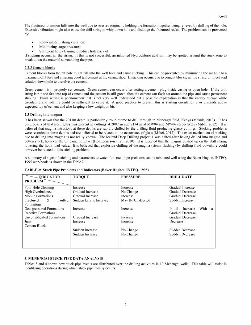
A summary of signs of sticking and parameters to watch for stuck pipe problems can be tabulated well using the Baker Hughes INTEQ,
1995 workbook as shown in the Table 2.
TABLE 2: Stuck Pipe Problems and Indicators (Baker Hughes, INTEQ, 1995)
INDICATOR
PROBLEM
TORQUE PRESSURE DRILL RATE
Poor Hole Cleaning
High Overbalance
Mobile Formations
Fractured & Faulted
Formations
Geo-pressured Formations
Reactive Formations
Unconsolidated Formations
Junk
Cement Blocks
Increase
Gradual Increase
Gradual Increase
Sudden Erratic Increase
Increase
Gradual Increase
Increase
Sudden Increase
Sudden Increase
Increase
No Change
Increase
May Be Unaffected
Increase
Increase
Increase
No Change
No Change
Gradual Increase
Gradual Decrease
Gradual Decrease
Sudden Increase
Initial Increase With a
Gradual Decrease
Gradual Decrease
Decrease
Sudden Decrease
Sudden Decrease
3. MENENGAI STUCK PIPE DATA ANALYSIS
Tables 3 and 4 shows how stuck pipe events are distributed over the drilling activities in 10 Menengai wells. This table will assist in
identifying operations during which stuck pipe mostly occurs.

Awili
6
TABLE 3: Drilling activities during Stuck Pipe/ in Menengai
Well Depth Of
Sticking
(m)
Activity During
Sticking
No. Of
Hours Stuck
Freed Hours
spent
Fishing
Total drilling
days (spud in to
capping)
Total Depth
(m)
MW01 114
125
380
378
2206
Drilling
Drilling
POOH
Casing-Stuck Casing
Drilling
1
3
3
-
8
YES
YES
YES
YES
YES
0
0
0
0
0
79
2206
MW02 109
133
135
165
207
213
218
POOH
RIH
Ream
POOH
Drilling
Drilling
Drilling/Reaming
72
<12
<12
1
3
17
77
yes
yes
yes
yes
Yes
Yes
yes
0
0
0
0
0
-
125
3200
MW03 113
167
1187
2093
Drilling
Drilling
Drilling
Drilling/Reaming
0.75
0.5
0.5
216
Yes
Yes
Yes
No-back off
0
0
0
648
100
2112
MW04 2117 Drilling 216 No-parted string 0 83 2117
MW06 2202 Drilling 268 No-parted string 0 96 2202
MW07 59
105
149
151
1184
2135
Drilling
Drilling
Drilling/Reaming
Drilling
POOH
Drilling
27
<6
20
5
37
9
Yes
Yes
Yes
Yes
Yes
No-parted string
0
0
0
0
0
0
132
2136
MW08 58 Drilling 1 yes 0 126 2355
MW09 1950 Drilling 1 yes 0 107 2088
MW13 1648 RIH 2 yes 0 161 2012
MW21 326 Drilling 4 yes 0 2730
Awili
7
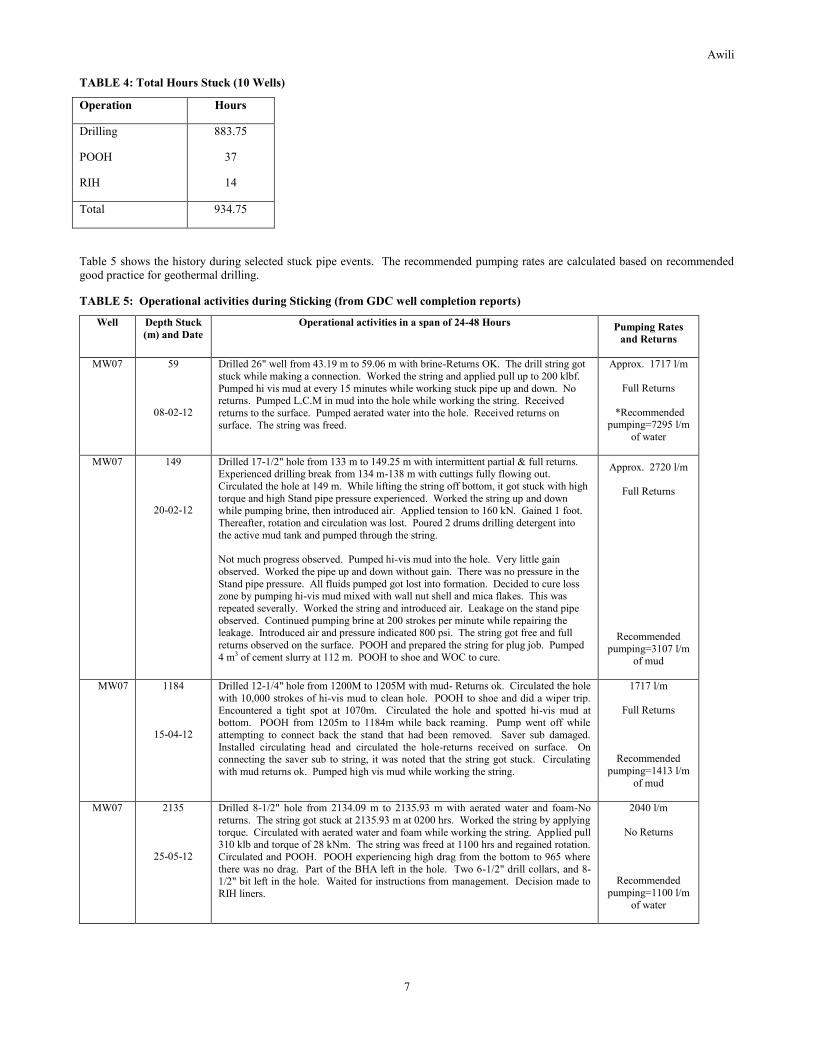
TABLE 4: Total Hours Stuck (10 Wells)
Operation Hours
Drilling
POOH
RIH
883.75
37
14
Total 934.75
Table 5 shows the history during selected stuck pipe events. The recommended pumping rates are calculated based on recommended
good practice for geothermal drilling.
TABLE 5: Operational activities during Sticking (from GDC well completion reports)
Well Depth Stuck
(m) and Date
Operational activities in a span of 24-48 Hours Pumping Rates
and Returns
MW07 59
08-02-12
Drilled 26" well from 43.19 m to 59.06 m with brine-Returns OK. The drill string got
stuck while making a connection. Worked the string and applied pull up to 200 klbf.
Pumped hi vis mud at every 15 minutes while working stuck pipe up and down. No returns. Pumped L.C.M in mud into the hole while working the string. Received
returns to the surface. Pumped aerated water into the hole. Received returns on
surface. The string was freed.
Approx. 1717 l/m
Full Returns
*Recommended pumping=7295 l/m
of water
MW07 149
20-02-12
Drilled 17-1/2" hole from 133 m to 149.25 m with intermittent partial & full returns. Experienced drilling break from 134 m-138 m with cuttings fully flowing out.
Circulated the hole at 149 m. While lifting the string off bottom, it got stuck with high
torque and high Stand pipe pressure experienced. Worked the string up and down while pumping brine, then introduced air. Applied tension to 160 kN. Gained 1 foot.
Thereafter, rotation and circulation was lost. Poured 2 drums drilling detergent into
the active mud tank and pumped through the string.
Not much progress observed. Pumped hi-vis mud into the hole. Very little gain
observed. Worked the pipe up and down without gain. There was no pressure in the
Stand pipe pressure. All fluids pumped got lost into formation. Decided to cure loss zone by pumping hi-vis mud mixed with wall nut shell and mica flakes. This was
repeated severally. Worked the string and introduced air. Leakage on the stand pipe
observed. Continued pumping brine at 200 strokes per minute while repairing the leakage. Introduced air and pressure indicated 800 psi. The string got free and full
returns observed on the surface. POOH and prepared the string for plug job. Pumped
4 m3 of cement slurry at 112 m. POOH to shoe and WOC to cure.
Approx. 2720 l/m
Full Returns
Recommended
pumping=3107 l/m of mud
MW07 1184
15-04-12
Drilled 12-1/4" hole from 1200M to 1205M with mud- Returns ok. Circulated the hole
with 10,000 strokes of hi-vis mud to clean hole. POOH to shoe and did a wiper trip.
Encountered a tight spot at 1070m. Circulated the hole and spotted hi-vis mud at bottom. POOH from 1205m to 1184m while back reaming. Pump went off while
attempting to connect back the stand that had been removed. Saver sub damaged.
Installed circulating head and circulated the hole-returns received on surface. On connecting the saver sub to string, it was noted that the string got stuck. Circulating
with mud returns ok. Pumped high vis mud while working the string.
1717 l/m
Full Returns
Recommended
pumping=1413 l/m
of mud
MW07 2135
25-05-12
Drilled 8-1/2" hole from 2134.09 m to 2135.93 m with aerated water and foam-No
returns. The string got stuck at 2135.93 m at 0200 hrs. Worked the string by applying
torque. Circulated with aerated water and foam while working the string. Applied pull 310 klb and torque of 28 kNm. The string was freed at 1100 hrs and regained rotation.
Circulated and POOH. POOH experiencing high drag from the bottom to 965 where
there was no drag. Part of the BHA left in the hole. Two 6-1/2" drill collars, and 8-1/2" bit left in the hole. Waited for instructions from management. Decision made to
RIH liners.
2040 l/m
No Returns
Recommended
pumping=1100 l/m
of water

Awili
8
MW09 1948
22-10-12
Drilling 8½″ hole with aerated water and foam. Partial returns.
Drill string sticking from 2300 hrs to 0000 hrs.
2210 l/m. Partial
Returns.
Recommended pumping=1100 l/m
of water
MW21 326
28-12-13
Drilling 17-1/2" hole with water and mud sweeps till 326m. Got stuck at 0200 hours and lost circulation. Circulated hi-vis mud while working the string for 4 hours when
string was freed .POOH after circulating to remove collapsed debris. POOH to 291 m
and reaming the section between 291m and 326 m.
3060 l/m- Full Returns
*Recommended
pumping=6213 l/m of water
*these water pumping rates are practically difficult to achieve and therefore the problem is mitigated by using high viscosity mud
sweeps at regular intervals to ensure sufficient hole cleaning. We also note that the upper sections of a well are usually drilled with
slower ROP, and therefore the fluid annular velocity necessary for sufficient hole cleaning is lower. Cuttings also reach the surface
faster since the well is still shallow.
3.1 Easy View Diagrams and Analysis
Drilling parameters during selected stuck pipe events were analysed using Easy View Software to easily recognize trends at the moment
of sticking and before the stuck pipe event. The drilling data was recorded using data loggers at the rig site. This data was then
downloaded in excel files in 10 second intervals and has been the input into Easy View software. This analysis will assist in identifying
the causes of the stuck pipe and possible solutions. The diagrams have been displayed and described in the subsequent pages. Other
conditions not captured by the data loggers during the stuck pipe events have also been listed (these other conditions include pumping
rates and amount of returns at shale shakers)
3.1.1 MW07: Stuck at 2135m at 0145 hrs. during drilling
The trend in Figure 4 shows that the string got stuck at 0145 hrs. We see a sudden drop in WOB from 5.92 to 0 kN, the rpm also drops
to 0 from 70. The pump rate, bit location and ROP remain constant. It can be observed that the driller then tries to pick up the string
and it is stuck as it has to be pulled to over 84.35 tonnes. There were no circulation returns at the moment of sticking and pumping rate
was 2040 l/m of aerated foam and water.
Figure 4: Parameters at sticking of MW07 at 2135 m
The trends prior to sticking are displayed in Figure 5. From 0100 hrs to sticking time at 0145 hrs, stand pipe pressure varies by 3 bars
(between 5,27MPa & 4.97 MPa). The other parameters appear to be unchanging. Pumping rate was 2040 l/m of aerated foam & water
and there were no returns prior to the sticking.

Awili
9
Figure 5: Parameters prior to sticking of MW07 at 2135 m
3.1.2 MW09: Stuck at 1948 m at 2229 hrs during drilling
The trend in Figure 6 shows the parameters at the moment of sticking of MW09 at 1948 m. The trends prior to sticking are shown in
Figure 7.
Figure 6: Parameters at sticking of MW09 at 1948 m
We see that the string gets stuck at 2229 hrs when the rotation speed and rotary torque suddenly drop to zero. This occurs at the end of
the drill pipe joint evidenced by the value of hook height i.e. the hook height is constant at about 0.41 m which implies it is the end of
the current drill pipe joint. WOB is also observed to dip to zero. Pump rate and pressure do not change. There were partial returns
during this stuck pipe event and pumping rate was 2210 l/m of aerated water and foam. The trends prior to sticking show that the
rotation speed, pipe pressure and torque are quite regular through the drilling of this joint of drill pipe just until sticking point.

Awili
10
Figure 7: Parameters prior to sticking of MW09 at 1948 m
The results seen in the above diagrams imply that the possible reasons and types of sticking are as shown in table 6. Parameters not
captured in Easy View have been obtained from Menengai well completion reports (see table 5). The possible causes are inferred from
notes on stuck pipe that had been discussed earlier in this paper. The data necessary to carry out the Easy View analysis for most of the
stuck pipe incidents, especially for the earlier wells were unavailable.
TABLE 6: Possible Causes of Stuck Pipe in Menengai Wells
Well Depth
Stuck
Torque WOB ROP Returns Other Possible Cause
MW07
MW07
2135 m Increase Unchanged Increase No Well
inclined
24
degrees
Pack-off caused by
poor hole cleaning or
a new lost circulation
zone.
59 m Freed by switching from drilling with brine to aerated fluid. Settled cuttings
due to poor hole
cleaning.
MW07
MW07
149 m
1184 m
Sudden
Increase
_ Sudden
Increase
Full Pipe Pressure
Increase
Fractured &
faulted
formation.
Differential
Sticking
Freed by pumping water instead of mud
MW09 1948 m Sudden Drop Unchanged Unchanged Partial Rotation
speed
suddenly 0.
Fractured &
faulted
formation.
Cement
Block/Junk
MW21
326 m Unchanged Unchanged Sudden
Decrease
PARTIAL Circulated
till free
Poor Hole
Cleaning
4. DISCUSSION AND CONCLUSION
The results show that the causes of stuck pipe are several in Menengai. Unconsolidated formation is problematic but has been mitigated
through using cement plugs. As earlier mentioned sticking due to fracture and faulted formation can be controlled by reducing drill
string vibration, minimizing surge pressures and sufficient hole cleaning to reduce hole pack off. Sticking due to poor hole cleaning can
be reduced by ensuring the hole is clean of cuttings. There are several ways to ensure good hole cleaning including ensuring good mud

Awili
11
rheology especially yield point and gel strength, controlling drill rate to ensure hole is clean, checking volume of cuttings coming over
to shale shaker and controlling annular velocities. Sticking caused by drilling through micro doglegs and ledges can be prevented by
running slowly when tripping at alternating formation points; these areas should be noted and reamed through during trips.
4.1 Loss of Returns While Drilling With Water and Air
Drilling the production zone is quite a challenge especially when there are no returns & cuttings cannot be carried to surface. The
drilling program in Menengai usually recommends blind drilling in the production section when there are no returns. The choice of
drilling fluid is restricted to water, aerated fluid and foam. Mud improves hole cleaning but cannot be used in the production zone since
it will block the sensitive feeder zones. This problem can be solved by use of liquid drilling fluid polymer. This compound increases
water viscosity thereby helping a lot with cutting carrying capacity; it does not affect formation permeability adversely. Polymer
however does not improve gel strength and will therefore not suspend cuttings if pumping is stopped. Sweeping the hole with polymer
can however still be introduced in Menengai to assist in hole cleaning as it has been successfully used in Iceland.
4.2 Drill String snapping/ tubular washout
An incident of snapped string was encountered after one day of working stuck pipe at MW07 at 2135 m. Pull applied was 310,000 lb.
force and 28 kNm torque which was still not exceeding the yield point (378,605 lb. force tensile yield strength and 53 kNm torsional
yield strength) of the 5’’ OD drill pipe (considered the weakest member of the drill string). The BHA snapped at a collar connection.
Weakening of drill string members could be caused by drilling fluid wash out or corrosion by acidic water that is used as drilling fluid.
These two problems can be solved by use of corrosion inhibitor compounds and by use of caustic soda in drilling fluid. Caustic soda is
used to maintain alkalinity so that acidic fluids do not attack metal. Corrosion inhibitors work by various mechanisms to inhibit oxygen
present in drilling/production fluids from corroding pipes or equipment (Schlumberger Drilling, 2014). It has also been shown that
aerated fluids erode drill pipes at a higher rate than non-aerated fluids (Budi Kesuma Adi Putra, 2008).
4.3 Deviation Surveys
These can greatly assist in correcting trajectories and avoiding sticking related to hole geometry. The Totco survey tool and the
Electronic Multi Shot tool can be dropped in the drill string during trip outs to quickly measure inclination. These tools are popular
since they eliminate the non-productive time associated with setting up a conventional deviation survey.
NOMENCLATURE
BHA = Bottom Hole Assembly;
ECD = Equivalent Circulating Density;
ft = Feet;
hi-vis = High viscosity;
klbf = Kilo pounds-force;
klbs = Kilo pounds;
kN = Kilo Newtons;
kNm = Kilo Newtons-metres;
lb = Pound;
l/m = Litres per minute;
LCM = Lost circulation material;
m = Metre;
POOH = Pull out of hole;
psi = Pascals per square inch;
RIH = Run in hole;
ROP = Rate of penetration (m/h);
RPM = Revolution per minute;
Spm = Strokes per minute;
WOB = Weight on bit (kN);

Awili
12
WOC = Wait on cement;
" = Inches.
REFERENCES
Baker Hughes INTEQ: Drilling engineering workbook. Baker Hughes INTEQ, USA, 410 pp, (1995)
Budi Kesuma Adi Putra, I.M.: Drilling practice with aerated drilling fluid. Report 11 in: Geothermal Training in Iceland 2008. UNU-
GTP, Iceland, (2008), 77-100.
GDC: Menengai Well MW-16 geology report. Geothermal Development Company – GDC, unpublished, internal report, 27 pp. (2013).
Hólmgeirsson, S., Gudmundsson, Á., Pálsson, B., Bóasson, H., Ingason, K., and Thórhallsson S.: Drilling operations of the first Iceland
deep drilling well (IDDP). Proceedings of the World Geothermal Congress 2010, Bali, Indonesia, 10 pp. (2010).
Makuk, I.K.: Reducing geothermal drilling problems to improve performance in Menengai. Report 16 in: Geothermal training in
Iceland 2013. UNU-GTP, Iceland, (2013), 325-358.
Mibei, G.: Geology and hydrothermal alteration of Menengai geothermal field. Case study: wells MW-04 and MW-05. Report 21 in:
Geothermal training in Iceland 2012. UNU-GTP, Iceland, (2012), 437-465.
Okwiri, L.A.: Geothermal drilling time analysis: A case study of Menengai and Hengill. Report 25 in: Geothermal training in Iceland
2013. UNU-GTP, Iceland, (2013), 577-598.
Rabia, H.: Well engineering and construction (e-book). Entrac Consulting, UK, (2001), 779 pp.
Schlumberger: Schlumberger oilfield review 1991. Schlumberger, report, October, (1991), 13-26.
Schlumberger Drilling, 2014: Corrosion inhibitor. Schlumberger M-I SWACO, Ltd., webpage,
www.slb.com/services/miswaco/services/completions/packer_fluids/corrosion_inhibitors.aspx.