Analysis of stainless steel-concrete composite...
11
Analysis of stainless steel-concrete composite beams R. Shamass a, ⁎, K.A. Cashell b a Division of Civil and Building Services Engineering, School of Build Environment and Architecture, London South Bank University, UK b Dept of Civil and Environmental Engineering, Brunel University London, UK abstract article info Article history: Received 21 November 2017 Accepted 29 May 2018 Available online 19 June 2018 Stainless steel is increasingly popular in construction projects owing to its corrosion-resistance, excellent me- chanical and physical properties and its aesthetic appearance. The current paper is concerned with the use of these materials in steel-concrete composite beams, which is an entirely new application. Current design codes for steel-concrete composite beams are based on elastic-perfectly plastic steel material behaviour neglecting strain hardening. Whilst this is a reasonable assumption for carbon steel, stainless steel is a very ductile material which offers significant levels of strain hardening prior to failure. Therefore, current design provisions typically result in inaccurate and overly-conservative strength predictions when applied to stainless steel composite beams. The current study presents for the first time, an analytical solution for predicting the plastic bending ca- pacity of stainless steel–concrete composite beams with either full or partial shear connection. This method is a development of the continuous strength method (CSM). Since the analytical analysis requires complex mathe- matical solution, a simplified analytical solution is also proposed, utilising some of the assumptions in Eurocode 4. There are no tests currently available in the literature for stainless steel-concrete composite beams. Therefore, a finite-element model is developed and validated against a number of experimental results for composite beams made from normal or high strength carbon steel. The validated numerical model is then used to investigate the accuracy of the proposed analytical solution. It is concluded that both the full and simplified analytical solutions are reliable and the simplified analytical method provides a straight forward design tool for practical engineers. © 2018 Elsevier Ltd. All rights reserved. Keywords: Stainless steel Composite beams Finite-element analysis, analytical analysis Continuous strength method Eurocodes 1. Introduction This paper is concerned with the behaviour of composite beams made from stainless steel. Steel-concrete composite members are widely used in the design and construction of modern structures such as bridges and high rise buildings. Depending on the degree of compos- ite action, a significant increase in strength and stiffness performance is gained compared to a bare steel or concrete section. This results in sav- ings not only in construction depth but also in terms of material con- sumption, which means also lower environmental impact and reduced energy consumption [1]. Composite beams which are subjected to positive bending (i.e. sagging) offer a particularly efficient use of the constituent materials. In this case, the steel section is subjected to ten- sile stresses whilst the concrete slab acts primarily in compression, thus utilising the favourable characteristics of each material. It is generally desirable for plastic design that composite beams have a ductile cross-section, in which strain hardening develops in the lower flange before the collapse moment is reached [2]. However, for calculat- ing the load-bearing capacity of composite beams, design codes such as Eurocode 4 [3] generally neglect strain hardening effects and employ a rigid-plastic analysis of the cross-section, thus providing conservative predictions of the capacity in many cases, particularly when ductile ma- terials such as stainless steel are employed. Stainless steel has been employed in construction since the 1920s, when the main usage was in building facades. Nowadays, stainless steel has become popular in a wide range of construction and load-bear- ing applications due to its excellent mechanical properties such as higher strength and ductility, better retention of strength and stiffness at high temperature [4] and excellent corrosion resistance properties, compared with carbon steel. Stainless steel does not require coatings to be applied, thus leading to life-cycle cost savings relative to carbon steel especially for offshore steel structures [5], as well as reducing maintenance and rehabilitation costs. In recent years, stainless steel has been the subject of intensive re- search in order to provide useful, efficient and reliable design guidance for engineers. The vast majority of research into stainless steel has been focussed on bare steel elements. Researchers have investigated the flex- ural behaviour of stainless steel columns subjected to compressive load- ing or combined compression and bending moment (e.g. [6–9]) and beams (e.g. [10–13]) as well as beams and columns under fire condi- tions (e.g. [14]). The use of stainless steel in composite structures has hitherto re- ceived little attention from the engineering community and research Journal of Constructional Steel Research 152 (2019) 132–142 ⁎ Corresponding author. E-mail address: [email protected] (R. Shamass). https://doi.org/10.1016/j.jcsr.2018.05.032 0143-974X/© 2018 Elsevier Ltd. All rights reserved. Contents lists available at ScienceDirect Journal of Constructional Steel Research
Transcript of Analysis of stainless steel-concrete composite...

Journal of Constructional Steel Research 152 (2019) 132–142
Contents lists available at ScienceDirect
Journal of Constructional Steel Research
Analysis of stainless steel-concrete composite beams
R. Shamass a,⁎, K.A. Cashell ba Division of Civil and Building Services Engineering, School of Build Environment and Architecture, London South Bank University, UKb Dept of Civil and Environmental Engineering, Brunel University London, UK
⁎ Corresponding author.E-mail address: [email protected] (R. Shamass).
https://doi.org/10.1016/j.jcsr.2018.05.0320143-974X/© 2018 Elsevier Ltd. All rights reserved.
a b s t r a c t
a r t i c l e i n f oArticle history:Received 21 November 2017Accepted 29 May 2018Available online 19 June 2018
Stainless steel is increasingly popular in construction projects owing to its corrosion-resistance, excellent me-chanical and physical properties and its aesthetic appearance. The current paper is concerned with the use ofthese materials in steel-concrete composite beams, which is an entirely new application. Current design codesfor steel-concrete composite beams are based on elastic-perfectly plastic steel material behaviour neglectingstrain hardening. Whilst this is a reasonable assumption for carbon steel, stainless steel is a very ductile materialwhich offers significant levels of strain hardening prior to failure. Therefore, current design provisions typicallyresult in inaccurate and overly-conservative strength predictions when applied to stainless steel compositebeams. The current study presents for the first time, an analytical solution for predicting the plastic bending ca-pacity of stainless steel–concrete composite beams with either full or partial shear connection. This method is adevelopment of the continuous strength method (CSM). Since the analytical analysis requires complex mathe-matical solution, a simplified analytical solution is also proposed, utilising some of the assumptions in Eurocode4. There are no tests currently available in the literature for stainless steel-concrete composite beams. Therefore, afinite-element model is developed and validated against a number of experimental results for composite beamsmade from normal or high strength carbon steel. The validated numerical model is then used to investigate theaccuracy of the proposed analytical solution. It is concluded that both the full and simplified analytical solutionsare reliable and the simplified analytical method provides a straight forward design tool for practical engineers.
© 2018 Elsevier Ltd. All rights reserved.
Keywords:Stainless steelComposite beamsFinite-element analysis, analytical analysisContinuous strength methodEurocodes
1. Introduction
This paper is concerned with the behaviour of composite beamsmade from stainless steel. Steel-concrete composite members arewidely used in the design and construction of modern structures suchas bridges and high rise buildings. Depending on the degree of compos-ite action, a significant increase in strength and stiffness performance isgained compared to a bare steel or concrete section. This results in sav-ings not only in construction depth but also in terms of material con-sumption, which means also lower environmental impact andreduced energy consumption [1]. Composite beamswhich are subjectedto positive bending (i.e. sagging) offer a particularly efficient use of theconstituent materials. In this case, the steel section is subjected to ten-sile stresses whilst the concrete slab acts primarily in compression,thus utilising the favourable characteristics of each material.
It is generally desirable for plastic design that composite beams havea ductile cross-section, in which strain hardening develops in the lowerflange before the collapsemoment is reached [2]. However, for calculat-ing the load-bearing capacity of composite beams, design codes such asEurocode 4 [3] generally neglect strain hardening effects and employ a
rigid-plastic analysis of the cross-section, thus providing conservativepredictions of the capacity inmany cases, particularly when ductile ma-terials such as stainless steel are employed.
Stainless steel has been employed in construction since the 1920s,when the main usage was in building facades. Nowadays, stainlesssteel has becomepopular in awide range of construction and load-bear-ing applications due to its excellent mechanical properties such ashigher strength and ductility, better retention of strength and stiffnessat high temperature [4] and excellent corrosion resistance properties,compared with carbon steel. Stainless steel does not require coatingsto be applied, thus leading to life-cycle cost savings relative to carbonsteel especially for offshore steel structures [5], as well as reducingmaintenance and rehabilitation costs.
In recent years, stainless steel has been the subject of intensive re-search in order to provide useful, efficient and reliable design guidancefor engineers. The vast majority of research into stainless steel has beenfocussed on bare steel elements. Researchers have investigated the flex-ural behaviour of stainless steel columns subjected to compressive load-ing or combined compression and bending moment (e.g. [6–9]) andbeams (e.g. [10–13]) as well as beams and columns under fire condi-tions (e.g. [14]).
The use of stainless steel in composite structures has hitherto re-ceived little attention from the engineering community and research

133R. Shamass, K.A. Cashell / Journal of Constructional Steel Research 152 (2019) 132–142
studies have generally been limited to investigating the behaviour ofconcrete-filled stainless steel columns under different loading condi-tions using experimental and numerical analysis. Lam et al. [15] con-ducted experiments on the behaviour of axially loaded concrete-filledstainless steel elliptical sections made from normal and high strengthconcrete. Uy et al. [16] carried out experiments on concrete-filled stain-less steel circular, square and rectangular sections of short and slendercolumns subjected to combined axial compression and bending mo-ment. The behaviour of concrete-filled stainless steel circular and squaretubular sections subjected to axial compression under fire conditionshas also been studied through a series of experiments [17]. Moreover,nonlinear finite-element analysis was used to investigate the perfor-mance of concrete-filled stainless steel tubular columns of square, L-,T-, and + shape sections under axial compression or combined com-pression and bending moment [18, 19]. To date, there has been no re-search available in the public domain on traditional composite beams(i.e. a bare steel section connected to a concrete slab through shear con-nectors) using stainless steel. The following section describes the con-text in which these members are highly relevant in the current era.
2. Research significance and methodology
Stainless steel provides excellent mechanical properties, durabilityand fire resistance for structural applications, and can also reduce themaintenance costs required over the lifetime of a structure, comparedwith carbon steel. However, it is only in very recent years as the de-mands for more sustainable construction have been given higher prom-inence, that stainless steel has really become an attractive solution forcertain applications. This growth in popularity has been accompaniedby an increase in research although most of the studies to date hasbeen limited to bare stainless steel elements as well as a few studiesinto concrete-filled stainless steel tubular sections. There has been noresearch, at least in the public domain, into the behaviour of compositebeams using stainless steel elements acting together with a concreteslab. Nevertheless, in appropriate scenarios, this type of applicationcould be ideal for stainless steel owing to its ductility and durability. Inparticular, stainless steel composite beams could offer a very valuablesolution in bridge applications, where harsh environments and difficultmaintenance requirements pose an ever-increasing challenge to engi-neers. In such applications, the stainless section could be left exposedto the local environment without long-term maintenance require-ments, thus reducing the life-cycle costs compared with carbon steeland also utilising the significant aesthetic appeal of stainless steel.
In addition to its durability credentials, stainless steel also has excel-lent mechanical properties especially in terms of ductility, toughnessand resistance to fatigue, all ofwhich are particularly relevant in bridgesand structural applications in harsh environments. Stainless steels havegreater ductility and capacity for work hardening compared with car-bon steels. A ductile cross-section is necessary for plastic design andhighly desirable for design in general so that warning is given beforecollapse and for moment redistribution to occur. According to currentdesign codes, the plastic bending resistance of composite steel-concretebeams is determined by rigid-plastic theory in which the effective areaof the steel member is stressed to its yield strength, neglecting any stainhardening effects in the steel. Although this is a reasonable assumptionfor carbon steel which has an elastic response, with a clearly definedyield point, followed by a yield plateau and a moderate degree of strainhardening, stainless steel has a nonlinear stress–strain response fromvery early stages as well as significant levels of strain hardening priorto failure. Therefore, the current design codes for composite carbonsteel-concrete beams result in an incorrect plastic bending resistancewhen applied to members made from stainless steel.
In this context, the current study presents an analytical solution forestimating the bending resistance of composite stainless steel-concretebeams with either a full and partial shear connection, which are sub-jected to sagging moments. The proposed method is an adaptation of
the continuous strength method (CSM), which has been developedand validated extensively in recent years for structural steel (e.g. [20]),structural stainless steel (e.g. [21]) and, more recently, for carbonsteel-concrete composite beams [2]. Since there are no tests availableon stainless steel-concrete composite beams, a nonlinear finite elementmodel has been developed to study the response and investigate the ac-curacy of proposed analytical solution. Although the analytical solutionyields accurate strength predictions, it requires complex mathematicalsolution. Therefore, a simplified analytical solution is also proposed,utilising some of the assumptions of Eurocode 4 [3].
3. The continuous strength method (CSM)
The continuous strength method (CSM) is a relatively recent ap-proach for calculating the cross-sectional resistance of metallic mem-bers using two key components: (1) a base curve which defines thecontinuous relationship between compressive local buckling strain atthe ultimate load and the cross-section slenderness and (2) a materialmodel that allows for the stain hardening. Gardner and Nethercot [21]originally proposed the design method for stainless steel hollow sec-tions loaded in compression, bending or combined compression andbending. The design method was further extended to calculate thecross-sectional compression and bending resistance of other metallicmaterials such as aluminium and high strength steel [20] as well asopen stainless steel cross-sections subjected to various types of loading[22]. It was found that the method provides more accurate predictionsof the cross-sectional resistance compared with those obtained usingthe Eurocode 3 [23] and ASCE [24] design codes. In 2008, the term “con-tinuous strength method” was introduced, based on a continuous rela-tionship between (inelastic) local buckling and a rational exploitationof strain hardening [25]. Earlier versions of the CSM used theRamberg-Osgood material model for stainless steel which resulted in avery complex solution procedure. In later developments, a bi-linear,elastic, linear hardening material model was introduced to the method[26] before a more detailed quad-linear material model was includedwhich accounts for both the length of yield plateau and the strain hard-ening behaviour of hot-rolled structural steel [2]. These modificationsmake the CSM more straightforward and easy to apply in exploitingthe benefits of strain hardening. Furthermore, the CSMmethod was re-cently extended to incorporate composite construction for carbon steel-concrete beams under sagging bending moment, accounting for strainhardening in the steel element [2]. This proposed application of themethod was shown to provide a more accurate prediction of thecross-sectional capacity compared with Eurocode 4 [3].
4. Analytical model for composite beams with stainless steel
4.1. General
Stainless steel is usually divided into five different families in accor-dance with the chemical composition, including the austenitic, ferritic,martensitic, precipitation-hardening and duplex grades. Each group of-fers different mechanical, physical and chemical properties. However,the excellent strength, stiffness, ductility and durability properties ofthe austenitic and duplex gradesmake these themost common in struc-tural applications, with the ferritic grades also being used in appropriateapplications.
Stainless steel exhibits a very different constitutive responsecompared with carbon steel. Whereas carbon steel has a clear yieldpoint, and relatively little strain hardening thereafter, stainlesssteel has a predominantly nonlinear stress–strain relationship evenbefore yielding (see Fig. 1) with significant strain hardening in thepost-yield range. In the absence of a clearly defined yield point, thestress at an offset to the 0.2% plastic strain, i.e. the 0.2% proof strength(σ0.2), is typically used to define the yield stress for stainless steels.This is determined by drawing a line with a slope equal to the elastic

Fig. 1. Typical stress–strain relationship of stainless steel.
134 R. Shamass, K.A. Cashell / Journal of Constructional Steel Research 152 (2019) 132–142
modulus (E) between the 0.2% strain on the x-axis and the stress–strain curve. The ultimate tensile strength (σu) is typically around500–700 N/mm2 for austenitic stainless steels and600–1000 N/mm2 for the duplex grades (including hot and coldrolled material) [27]. In terms of ductility, the most common austen-itic and duplex grades have a fracture strain (εu) of around 40–60%and 20–30%, respectively, compared to around 20–25% for carbonsteel. It has been shown [28] that before yielding occurs, thestress–strain response can be idealised using the following relation-ship proposed by Ramberg-Osgood [29] and modified by Hill [30]:
ε ¼ σEþ 0:002
σσ0:2
� �n
ð1Þ
where n is a strain hardening exponent. Beyond yield, the followingexpression proposed byMirambell and Real [31] and Rasmussen [28]can be applied:
ε ¼ ε0:2 þ σ−σ0:2
E2þ ε�up
σ−σ0:2
σu−σ0:2
� �m
ð2Þ
where ε�up ¼ εu−ε0:2− σu−σ0:2E2
where ε0.2 is the total 0.2% strain corresponding to σ0.2 and m is astrain hardening coefficient. In the following sub-sections, the materialmodels discussed herein are used to develop both a full and simplifiedanalytical model, based on the continuous strength method approach,for stainless steel-concrete composite beams with full and partialshear connection.
Fig. 2. The stress and strain distribution diagrams fo
4.2. Full shear connection
4.2.1. Basic assumptions in the full analytical modelFor composite beams with full shear connection, where the shear
connection deformability is very small, a single plastic neutral axis(NA) exists. The position of the neutral axis and the plastic bendingmo-ment capacity can be identified by applying the equilibrium of internalforces equations to the cross-section. The full analytical model devel-oped in this section is based on the following assumptions:
- The plastic neutral axis is located within the concrete slab. Hence,the compressive force in the concrete is larger than the tensileforce in the steel element. This case is very common and desirablein composite beams to avoid any local buckling in the steel member.
- The slip that occurs between the steel section and the concrete slabis assumed to be negligible and therefore is ignored and the straindistribution over the composite cross section is linear with constantcurvature κ.
- Any reinforcement in the concrete slab is ignored in the calculations.
Although themodels defined in this paper are presented in the con-text of composite beams made using stainless steel, the expressions areequally relevant and applicable to traditional carbon steel compositemembers, with an appropriate material model.
4.2.2. Full analytical expressions to determine the bending resistanceThe full-range stress-strain relationship for stainless steel illustrated
in the literature (e.g. [28]) typically describes the strain as an explicitfunction of stress. However, in order to use the CSM in conjunctionwith an accuratematerial law for stainless steel, it is necessary to obtainthe stress as an explicit function of strain. Abdella [32] proposed an ap-proximate inversion relationshipwith the stress (σ) expressed as an ex-plicit function of strain (ε), as follows:
σ1 εð Þ ¼ σ0:2
rε
ε0:2
� �
1þ r−1ð Þ εε0:2
� �p for ε≤ε0:2 ð3Þ
σ2 εð Þ ¼ σ0:2 1þr2
εε0:2
−1� �
1þ r�−1ð Þε
ε0:2−1
εuε0:2
−1
� �p�
26664
37775 for εNε0:2 ð4Þ
where the material parameters are:
ε0:2 ¼ σ0:2
Eþ 0:002; r ¼ E ε0:2
σ0:2
E2 ¼ E1þ 0:002 n=e
; p ¼ r1−r2r−1
r composite beams with full shear connection.

Table 1Expressions for the internal forces and bending moments in the cross-section for the three cases.
Case 1 Case 2 Case 3
Fc 0.85 fc bc y1 0.85 fc bc y1 0.85 fc bc y1Mc 0:85 fc bc
y212 0:85 fc bc
y212 0:85 fc bc
y212
Ftf1 ∫tc−y1
tc−y1+t
fbf σ1(ε) dy ∫tc−y1
y0.2bf σ1(ε) dy ∫tc−y1tc−y
1+t
fbf σ2(ε) dyMtf1 ∫tc−y1
tc−y1+t
fbf σ1(ε) y dy ∫tc−y1
y0.2bf σ1(ε)y dy ∫tc−y1tc−y
1+t
fbf σ2(ε)y dyFtf2 ∫H−tf−y1
H−y1bf σ1(ε) dy ∫H−tf−y1
H−y1bf σ2(ε) dy ∫H−tf−y1
H−y1bf σ2(ε) dyMtf2 ∫H−tf−y1
H−y1bf σ1(ε)y dy ∫H−tf−y1
H−y1bf σ2(ε)y dy ∫H−tf−y1
H−y1bf σ2(ε)y dyFtf3 ----- ∫y0.2
tc−y1+t
ftw σ2(ε) dy -----Mtf3 ----- ∫y0.2
tc−y1+t
ftw σ2(ε)y dy -----Ftw1 ∫tc−y1+tf
y0.2tw σ1(ε) dy ----- -----Mtw1 ∫tc−y1+tf
y0.2tw σ1(ε) y dy ----- -----Ftw2 ∫y0.2
H−tf−y1tw σ2(ε) dy ∫tc−y1+tf
H−tf−y1tw σ2(ε) dy ∫tc−y1+tf
H−tf−y1tw σ2(ε) dy
Mtw2 ∫y0.2
H−tf−y1tw σ2(ε) y dy ∫tc−y1+tf
H−tf−y1tw σ2(ε)y dy ∫tc−y1+tf
H−tf−y1tw σ2(ε)y dy
135R. Shamass, K.A. Cashell / Journal of Constructional Steel Research 152 (2019) 132–142
e ¼ σ0:2
E; m ¼ 1þ 3:5
σ0:2
σu
σu ¼ σ0:21−0:0375 n−5ð Þ
0:2þ 185e; Eu ¼ E2
1þ r�−1ð Þm
r2 ¼ E2 ε0:2σ0:2
; ru ¼ Eu εu−ε0:2ð Þσu−σ0:2
εu ¼ min 1−σ0:2
σuA
� �; p� ¼ r�
1−rur�−1
r� ¼ E2 εu−ε0:2ð Þσu−σ0:2
In these expressions, εu is the ultimate tensile strain, A is the stain-less steel elongation, E2 and Eu are the slope of the stress–strain curveat ε0.2 and εu, respectively, and r, r2, r*, ru, p, p* and m are parametersthat need to be determined.
Fig. 2 shows the strain distribution through the depth of the cross-section for composite beams with a full shear connection togetherwith the corresponding stress distribution obtained using the materialmodel presented in Eqs. 3 and 4. In this figure, εa and εc are the strainat the bottom fibre of the stainless steel beam and top fibre of the con-crete slab, respectively. Since the stress–stain relationship of stainlesssteel consists of two unique expressions (Eqs. 1 and 2 for pre- andpost-yield, respectively), these, together with the compressive regionin the slab, result in three different stress distributions across thecross-section, as illustrated in Fig. 2. Assuming that y0.2 is the distancebetween the neutral axis (NA) and the location in the cross-sectionwhere the strain in the stainless steel section is ε0.2, it can bedeterminedthat:
y0:2 ¼ ε0:2κ
ð5Þ
Fig. 3. The strain and stress distribution diagrams for composite beam
As presented in Fig. 2, three possible cases are considered. Case 1 iswhen y0.2 is within the stainless steel web (i.e. y0.2 ≥ tc − y1 + tf,where y1, tc and tf are the depth of the compressive area of the concreteslab, the depth of the concrete slab and the thickness of the top flange ofthe stainless steel section, respectively), Case 2 corresponds to the situ-ation when y0.2 is within the top stainless steel flange (i.e. tc − y1 ≤ y0.2b tc + tf) while in Case 3, y0.2 is within the concrete slab (i.e. 0 b y0.2 b tc− y1).
Based on the strain distribution and the full stainless steel stress–strain material model, the internal axial forces within the concreteslab and each individual stainless steel component (i.e. the flanges andthe web) can be calculated for all three cases. These are presented inTable 1, in which fc is the concrete compressive strength and bc is thewidth of the concrete slab acting compositely with the stainless steelsection; σ1 and σ2 are the appropriate stresses in the stainless steel sec-tion (as defined in Eqs. 3 and 4); and bf is thewidth of the stainless steelflange. The axial forces (i.e. Ftf1, Ftf2, Ftf3, Ftw1, Ftw2 and Fc) are as definedin Fig. 2 and the correspondingmoments in the section are given asMtf1,Mtf2, Mtf3, Mtw1, Mtw2 and Mc, respectively.
The initial step in calculating theplastic bending capacity of the com-posite beam is to locate the position of the neutral axis at failure (i.e. y1).The position y1 can be obtained based on the equilibrium of internalforces, and is given as:
Ftf1 þ Ftf2 þ Ftf3 þ Ftw1 þ Ftw2−Fc ¼ 0 ð6Þ
In order to calculate the internal forces in Eq. 6 and presented in theTable 1, and hence y1, direct integration is required. Since the internalforces depend on the variable y1, Eq. 6 is a nonlinear problemwhich re-quires an iterative method to obtain a solution. In the current analysis,themathematical softwareMatlab [33] is employed to solve these com-plex equations and determine the position of neutral axis. The strain atany point in the cross-section (denoted as the position y, measuredfrom the NA) is calculated from the strain distribution and is
s with full shear connection based on the simplified approach.
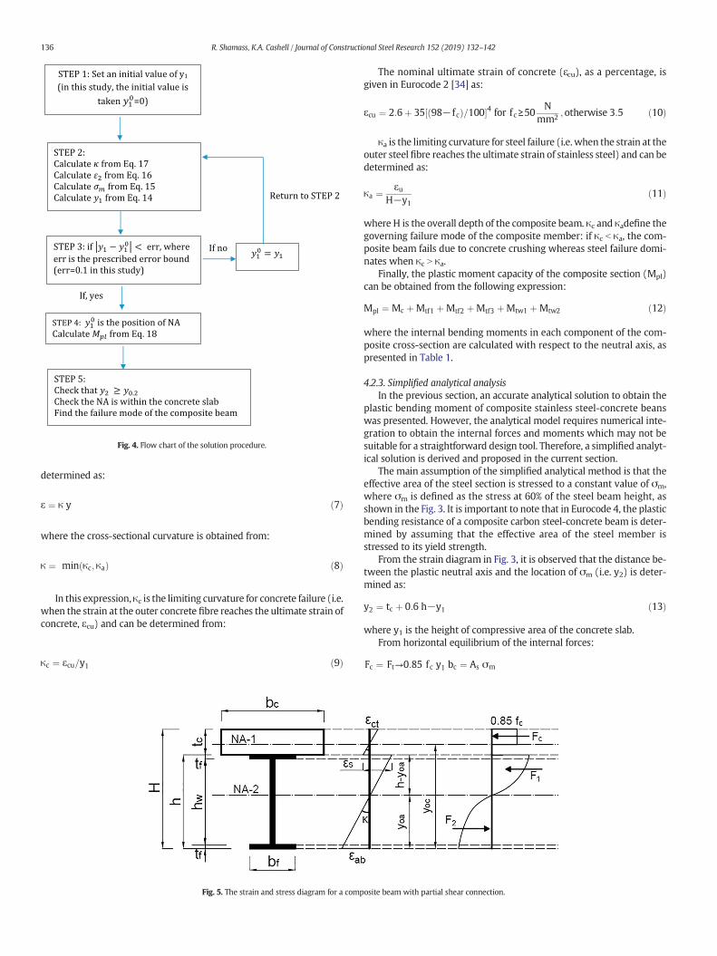
Fig. 4. Flow chart of the solution procedure.
136 R. Shamass, K.A. Cashell / Journal of Constructional Steel Research 152 (2019) 132–142
determined as:
ε ¼ κ y ð7Þ
where the cross-sectional curvature is obtained from:
κ ¼ min κc; κað Þ ð8Þ
In this expression,κc is the limiting curvature for concrete failure (i.e.when the strain at the outer concrete fibre reaches the ultimate strain ofconcrete, εcu) and can be determined from:
κc ¼ εcu=y1 ð9Þ
Fig. 5. The strain and stress diagram for a comp
The nominal ultimate strain of concrete (ɛcu), as a percentage, isgiven in Eurocode 2 [34] as:
εcu ¼ 2:6þ 35 98− fcð Þ=100½ �4 for fc ≥50N
mm2 ;otherwise 3:5 ð10Þ
κa is the limiting curvature for steel failure (i.e.when the strain at theouter steel fibre reaches the ultimate strain of stainless steel) and can bedetermined as:
κa ¼ εuH−y1
ð11Þ
where H is the overall depth of the composite beam. κc and κadefine thegoverning failure mode of the composite member: if κc b κa, the com-posite beam fails due to concrete crushing whereas steel failure domi-nates when κc N κa.
Finally, the plastic moment capacity of the composite section (Mpl)can be obtained from the following expression:
Mpl ¼ Mc þMtf1 þMtf2 þMtf3 þMtw1 þMtw2 ð12Þ
where the internal bending moments in each component of the com-posite cross-section are calculated with respect to the neutral axis, aspresented in Table 1.
4.2.3. Simplified analytical analysisIn the previous section, an accurate analytical solution to obtain the
plastic bending moment of composite stainless steel-concrete beanswas presented. However, the analytical model requires numerical inte-gration to obtain the internal forces and moments which may not besuitable for a straightforward design tool. Therefore, a simplified analyt-ical solution is derived and proposed in the current section.
The main assumption of the simplified analytical method is that theeffective area of the steel section is stressed to a constant value of σm,where σm is defined as the stress at 60% of the steel beam height, asshown in the Fig. 3. It is important to note that in Eurocode 4, the plasticbending resistance of a composite carbon steel-concrete beam is deter-mined by assuming that the effective area of the steel member isstressed to its yield strength.
From the strain diagram in Fig. 3, it is observed that the distance be-tween the plastic neutral axis and the location of σm (i.e. y2) is deter-mined as:
y2 ¼ tc þ 0:6 h−y1 ð13Þ
where y1 is the height of compressive area of the concrete slab.From horizontal equilibrium of the internal forces:
Fc ¼ Ft→0:85 fc y1 bc ¼ As σm
osite beam with partial shear connection.
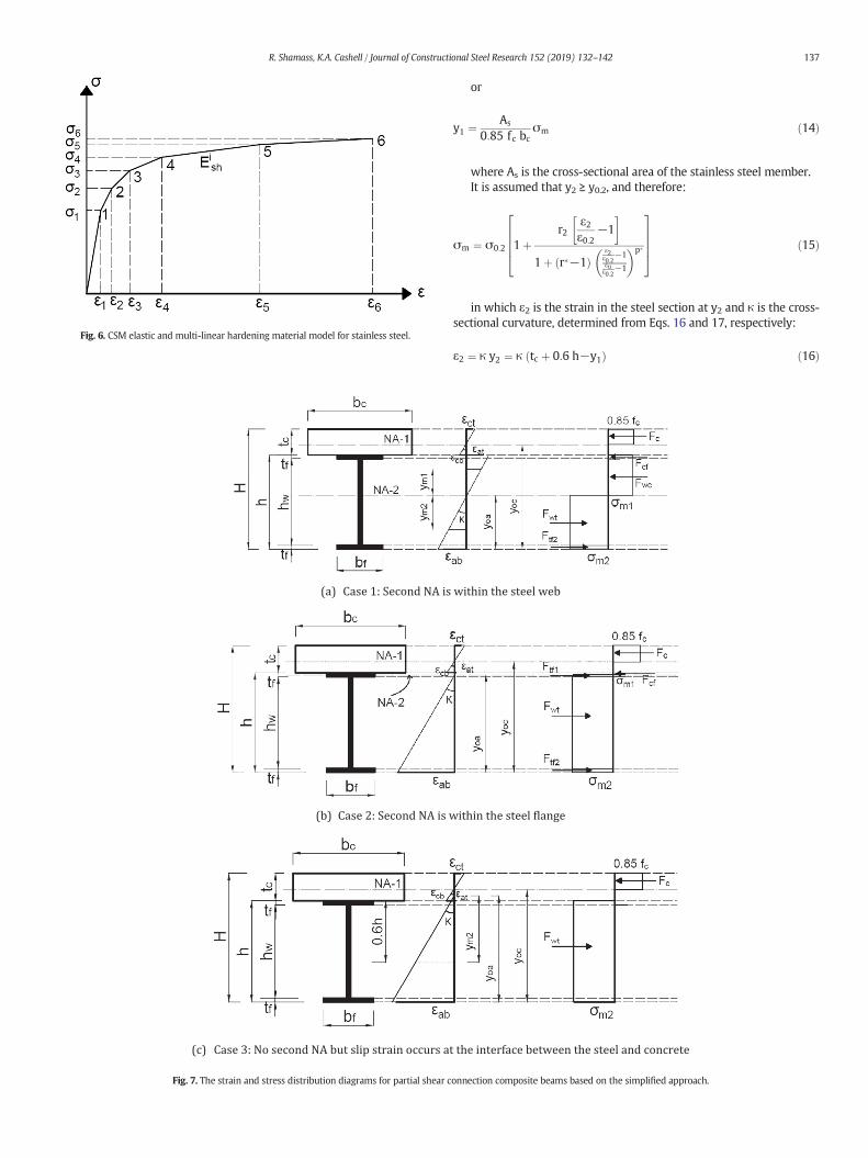
Fig. 7. The strain and stress distribution diagrams for partial shear c
Fig. 6. CSM elastic and multi-linear hardening material model for stainless steel.
137R. Shamass, K.A. Cashell / Journal of Constructional Steel Research 152 (2019) 132–142
or
y1 ¼ As
0:85 fc bcσm ð14Þ
where As is the cross-sectional area of the stainless steel member.It is assumed that y2 ≥ y0.2, and therefore:
σm ¼ σ0:2 1þr2
ε2ε0:2
−1� �
1þ r�−1ð Þε2ε0:2
−1εuε0:2
−1
� �p�
26664
37775 ð15Þ
in which ε2 is the strain in the steel section at y2 and κ is the cross-sectional curvature, determined from Eqs. 16 and 17, respectively:
ε2 ¼ κ y2 ¼ κ tc þ 0:6 h−y1ð Þ ð16Þ
onnection composite beams based on the simplified approach.
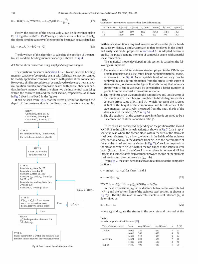
Table 2Geometry of the composite beams used for the validation study.
Section name bc (mm) tc (mm) tw (mm) h (mm) bf (mm) tf (mm)
S1 1200 100 10.2 304.8 152.4 18.2S2 1500 100 12 400 190 18.2
138 R. Shamass, K.A. Cashell / Journal of Constructional Steel Research 152 (2019) 132–142
κ ¼ min κc; κað Þwhere κc ¼ εcu=y1and κa ¼ εuH−y1
ð17Þ
Firstly, the position of the neutral axis y1 can be determined usingEq. 14 togetherwith Eqs. 15-17 using a trial and error technique. Finally,the plastic bending capacity of the composite beamcan be calculated as:
Mpl ¼ σm As H−h=2−y1=2½ � ð18Þ
The flow chart of the algorithm to calculate the position of the neu-tral axis and the bending moment capacity is shown in Fig. 4.
4.3. Partial shear connection using simplified analytical analysis
The equations presented in Section 4.3.2.3 to calculate the bendingmoment capacity of composite beamswith full shear connection cannotbe readily applied for composite beams with partial shear connection.However, a similar procedure can be employed to develop a newanalyt-ical solution, suitable for composite beams with partial shear connec-tion. In these members, there are often two distinct neutral axes lyingwithin the concrete slab and the steel section, respectively, as shownin Fig. 5 (NA-1 and NA-2 in the figure).
It can be seen from Fig. 5 that the stress distribution through thedepth of the cross-section is nonlinear and therefore a complex
Fig. 8. Flow chart of the solution procedure.
mathematical solution is required in order to calculate the plastic bend-ing capacity. Hence, a similar approach to that employed in the simpli-fied analytical model proposed in Section 4.2.3 is adopted herein topredict the plastic bending moment of composite beams with a partialshear connection.
The analytical model developed in this section is based on the fol-lowing assumptions:
1. The material model for stainless steel employed in the CSM is ap-proximated using an elastic, multi-linear hardening material model,as shown in the Fig. 6. An acceptable level of accuracy can beachieved by considering six points from the stress–strain curve ofstainless steel, as shown in the figure. It worth noting that more ac-curate results can be achieved by considering a larger number ofpoints from the material stress–strain response.
2. The nonlinear stress diagrams in the compressive and tensile areas ofthe stainless steel member are simplified to block diagrams with aconstant stress value of σm1 and σm2 which represent the stressesat 60% of the height of the compressive and tensile areas of thesteel member, respectively, measured from the neutral axis of thestainless steel member (NA-2 in Fig. 5).
3. The slip strain (εi) at the concrete-steel interface is assumed to be alinear function of shear connection ratio, β.
Three cases are considered, depending on the position of the secondNA (NA-2 in the stainless steel section), as shown in Fig. 7. Case 1 repre-sents the case where the second NA is within the web of the stainlesssteel beam element (yoa ≤ h − tf, where h is the height of the stainlesssteel section and yoa is the distance from NA-2 to the bottom fibre ofthe stainless steel section, as shown in Fig. 7), Case 2 corresponds tothe situation where NA-2 is within the top flange of the stainless steelbeam (h ≥ yoa N h − tf) and Case 3 is when there is no second NA butthere is still some relative displacement between the top of the stainlesssteel section and the concrete slab (yoa N h).
From Fig. 7, the cross-sectional curvature at failure of the compositesection is:
κ ¼ min κc;κa1;κa2ð Þ for Cases 1 and 2
κ ¼ min κc;κa2ð Þ ð19Þ
where κc ¼ εcuH−yoc
; κa1 ¼ εuh−yoa
; and κa2 = εu/yoa.
In these expressions, yoc is the distance between the concrete NA(NA-1) and the bottom fibre of the stainless steel section, as shown inFig. 7(a). The slip strain at the concrete-stainless steel interface (εs) isdetermined as:
εs ¼ εcb þ εat ð20Þ
where εcb and εat are the strains in the concrete and the steel at the
Table 3Material properties of stainless steel [23].
Type of stainless steel Grade σ0.2 (N/mm2) σu (N/mm2) n A (%)
Ferritic 1.4003 280 450 7 511.4016 260 450 6 381.4512 210 380 9 44
Austenitic 1.4571 220 520 7 401.4406 280 580 8 40
Duplex 1.4362 400 630 5 20

Table 4Comparison between the numerical and analytical bending moment for the beam S1.
Stainless steelgrade
Concretegrade
FE bending moment capacity,MFE (kNm)
Full analytical bending moment capacity,Man,full (kNm)
Simplified analytical bending momentcapacity, Man,simp (kNm)
Man;fullMFE
ð%Þ Man;simpMFE
ð%Þ
1.4003 C40 606.5 588.9 584 −2.9 −3.71.4016 C40 585.0 565.6 559 −3.3 −4.41.4512 C40 493.0 476.3 470.5 −3.4 −4.61.4571 C50 567.0 549.9 538.6 −3.0 −51.4406 C50 664.0 643.7 632.2 −3.1 −4.81.4362 C50 836.5 828.0 818.5 −1.0 −2.2
139R. Shamass, K.A. Cashell / Journal of Constructional Steel Research 152 (2019) 132–142
interface, respectively. These can be obtained from the following ex-pressions:
εcb ¼ κ yoc−hð Þ ð21Þ
εat ¼ κ h−yoað Þ ð22Þ
The slip at the interface can be found using Eq. 23 [35]:
εs ¼ 1−βð Þ h2þ tc
2
� �; κ ¼ α κ ð23Þ
where,
α ¼ 1−βð Þ h2þ tc
2
� �ð24Þ
Substituting Eqs. 21, 22 and 23 into Eq. 20, it can be established that:
yoc ¼ yoa þα ð25Þ
The distances ym1 and ym2, as indicated in Fig. 7(a), are where con-stant stresses are assumed, and are calculated as:
ym1 ¼ 0:6 h−yoað Þ for Case 1 and 2 ð26Þ
ym2 ¼ 0:6yoa for Case 1 and 2 ð27Þ
ym2 ¼ yoa−0:4h for Case 3 ð28Þ
It is noteworthy that the distance ym1 is not relevant in Case 3 as thewhole steel section is in compression.
The corresponding stresses at ym1 and ym2 are given by Eq. 29:
If yi−1≤ym1≤yi
σm1 ¼ σ i−1 þ Eish κ ym1−εi−1ð Þwhere i ¼ 1;2…;6 ð29aÞ
If yi−1≤ym2≤yi
σm2 ¼ σ i−1 þ Eish κ ym2−εi−1ð Þwhere i ¼ 1;2…;6 ð29bÞ
Table 5Comparison between the numerical and analytical bending moment for the beam S2.
Stainless steelgrade
Concretegrade
FE bending moment capacity,MFE (kNm)
Full analytical bending mMan,full (kNm)
1.4003 C40 967.2 977.231.4016 C40 930.0 939.11.4512 C40 791.0 789.21.4571 C50 913.0 916.01.4406 C50 1058.1 1062.01.4362 C50 1330.0 1370.0
The strains shown in Fig. 6 are assumed to be as follows:
ε0 ¼ 0; ε1 ¼ ε0:2; ε2 ¼ 3ε0:2; ε3 ¼ 5ε0:2; ε4 ¼ 10ε0:2; ε5 ¼ 0:3εu; ε6¼ εu ð30Þ
Accordingly, the corresponding stresses can be calculated as:
σ0 ¼ 0
σ1 ¼ σ0:2
σ i ¼ σ0:2 1þr2
εiε0:2
−1� �
1þ r�−1ð Þεi
ε0:2−1
εuε0:2
−1
� �p�
26664
37775; i ¼ 2;3;4;5
σ6 ¼ σu ð31Þ
and Eshi and yi are given as:
Eish ¼ σ i−σ i−1
εi−εi−1; i ¼ 1;…;6 ð32Þ
yi ¼ εi=κ; i ¼ 0;1;…::;6 ð33Þ
As before, the initial step to calculate the plastic bending capacity isto locate the positions of the neutral axes at failure, yoa and yoc. The po-sition yoa can be obtained based on the equilibrium of horizontal forces,given as:
Fc þ Fcf þ Fwc ¼ Fwt þ Ftf2 for Case 1 ð34aÞ
Fc þ Fcf ¼ Ftf1 þ Fwt þ Ftf2 for Case 2 ð34bÞ
Fc ¼ Fwtfor Case 3 ð34cÞ
From Fig. 7, the relationship between the internal forces and yoa canbe readily obtained. Substituting the resulting expression of the internalforces into Eqs 34a–c, the following equations are obtained:
yoa ¼0:85fcbc H−αð Þ þ σm1−σm2ð Þ bf−twð Þt f þ twσm1h
0:85fcbc þ tw σm1 þ σm2ð Þ for Case 1
ð35aÞ
oment capacity, Simplified analytical bending momentcapacity, Man,simp (kNm)
Man;fullMFE
ð%Þ Man;simpMFE
ð%Þ
965 1.0 −0.2925 1.0 −0.5777 −0.2 −1.8892 0.3 −2.31047 1.0 −1.051346 3.0 1.2
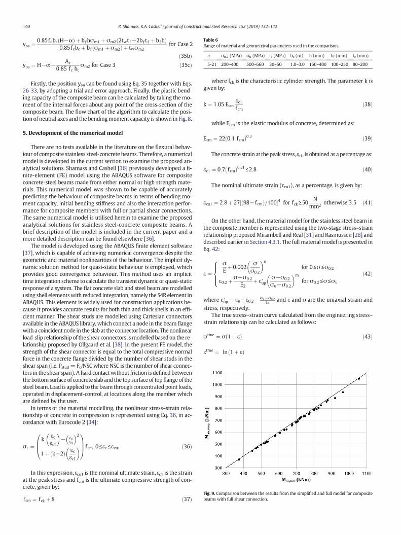
Fig. 9. Comparison between the results from the simplified and full model for compositebeams with full shear connection.
Table 6Range of material and geometrical parameters used in the comparison.
n σ0.2 (MPa) σu (MPa) fc (MPa) bc (m) h (mm) bf (mm) tc (mm)
5-21 200–400 500–660 30–50 1.0–3.0 150–400 100–250 80–200
140 R. Shamass, K.A. Cashell / Journal of Constructional Steel Research 152 (2019) 132–142
yoa ¼0:85fcbc H−αð Þ þ bfhσm1 þ σm2 2twtf−2bf t f þ bfhð Þ
0:85fcbc þ bf σm1 þ σm2ð Þ þ twσm2for Case 2
ð35bÞyoa ¼ H−α−
As
0:85 fc bcσm2 for Case 3 ð35cÞ
Firstly, the position yoa can be found using Eq. 35 together with Eqs.26-33, by adopting a trial and error approach. Finally, the plastic bend-ing capacity of the composite beam can be calculated by taking the mo-ment of the internal forces about any point of the cross-section of thecomposite beam. The flow chart of the algorithm to calculate the posi-tion of neutral axes and the bendingmoment capacity is shown in Fig. 8.
5. Development of the numerical model
There are no tests available in the literature on the flexural behav-iour of composite stainless steel-concrete beams. Therefore, a numericalmodel is developed in the current section to examine the proposed an-alytical solutions. Shamass and Cashell [36] previously developed a fi-nite-element (FE) model using the ABAQUS software for compositeconcrete-steel beams made from either normal or high strength mate-rials. This numerical model was shown to be capable of accuratelypredicting the behaviour of composite beams in terms of bending mo-ment capacity, initial bending stiffness and also the interaction perfor-mance for composite members with full or partial shear connections.The same numerical model is utilised herein to examine the proposedanalytical solutions for stainless steel-concrete composite beams. Abrief description of the model is included in the current paper and amore detailed description can be found elsewhere [36].
The model is developed using the ABAQUS finite element software[37], which is capable of achieving numerical convergence despite thegeometric and material nonlinearities of the behaviour. The implicit dy-namic solution method for quasi-static behaviour is employed, whichprovides good convergence behaviour. This method uses an implicittime integration scheme to calculate the transient dynamic or quasi-staticresponse of a system. The flat concrete slab and steel beam are modelledusing shell elementswith reduced integration, namely the S4R element inABAQUS. This element is widely used for construction applications be-cause it provides accurate results for both thin and thick shells in an effi-cient manner. The shear studs are modelled using Cartesian connectorsavailable in the ABAQUS library, which connect a node in the beamflangewith a coincident node in the slab at the connector location. Thenonlinearload-slip relationship of the shear connectors ismodelled based on the re-lationship proposed by Ollgaard et al. [38]. In the present FE model, thestrength of the shear connector is equal to the total compressive normalforce in the concrete flange divided by the number of shear studs in theshear span (i.e. Pstud= Fc/NSCwhere NSC is the number of shear connec-tors in the shear span). A hard contactwithout friction is defined betweenthe bottom surface of concrete slab and the top surface of topflange of thesteel beam. Load is applied to the beam through concentrated point loads,operated in displacement-control, at locations along the member whichare defined by the user.
In terms of the material modelling, the nonlinear stress–strain rela-tionship of concrete in compression is represented using Eq. 36, in ac-cordance with Eurocode 2 [34]:
σc ¼k
εcεc1
� �− εc
εc1
� �2
1þ k−2ð Þ εcεc1
� �0BB@
1CCAf cm;0≤εc ≤εcu1 ð36Þ
In this expression, ɛcu1 is the nominal ultimate strain, ɛc1 is the strainat the peak stress and fcm is the ultimate compressive strength of con-crete, given by:
fcm ¼ fck þ 8 ð37Þ
where fck is the characteristic cylinder strength. The parameter k isgiven by:
k ¼ 1:05 Ecmεc1fcm
ð38Þ
while Ecm is the elastic modulus of concrete, determined as:
Ecm ¼ 22 0:1 fcmð Þ0:3 ð39Þ
The concrete strain at thepeak stress, ɛc1, is obtained as apercentage as:
εc1 ¼ 0:7 fcmð Þ0:31≤2:8 ð40Þ
The nominal ultimate strain (ɛcu1), as a percentage, is given by:
εcu1 ¼ 2:8þ 27 98−fcmð Þ=100½ �4 for fck≥50N
mm2 otherwise 3:5 ð41Þ
On the other hand, thematerialmodel for the stainless steel beam inthe compositemember is represented using the two-stage stress–strainrelationship proposedMirambell and Real [31] and Rasmussen [28] anddescribed earlier in Section 4.3.1. The full material model is presented inEq. 42:
ε ¼σEþ 0:002
σσ0:2
� �n
for 0≤σ ≤σ0:2
ε0:2 þ σ−σ0:2
E2þ ε�up
σ−σ0:2
σu−σ0:2
� �m
for σ0:2≤σ ≤σu
8>><>>:
ð42Þ
where ε�up ¼ εu−ε0:2− σu−σ0:2E2
and ε and σ are the uniaxial strain andstress, respectively.
The true stress–strain curve calculated from the engineering stress–strain relationship can be calculated as follows:
σtrue ¼ σ 1þ εð Þ ð43Þ
εtrue ¼ ln 1þ εð Þ
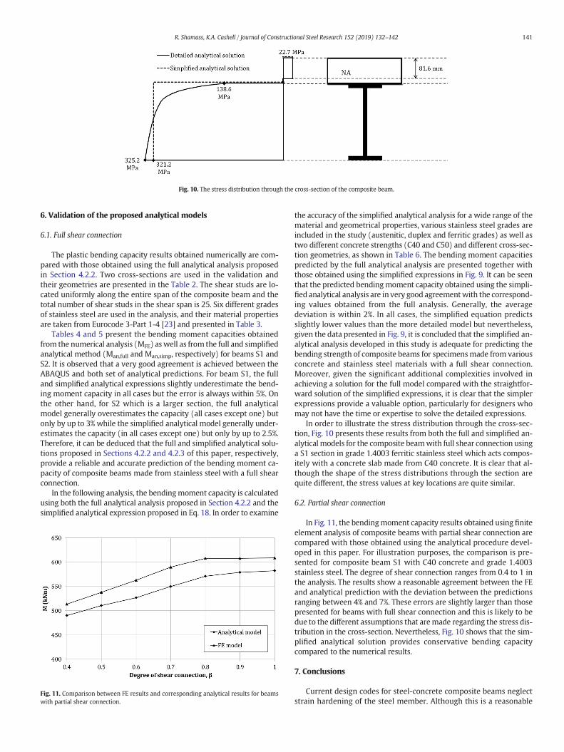
Fig. 10. The stress distribution through the cross-section of the composite beam.
141R. Shamass, K.A. Cashell / Journal of Constructional Steel Research 152 (2019) 132–142
6. Validation of the proposed analytical models
6.1. Full shear connection
The plastic bending capacity results obtained numerically are com-pared with those obtained using the full analytical analysis proposedin Section 4.2.2. Two cross-sections are used in the validation andtheir geometries are presented in the Table 2. The shear studs are lo-cated uniformly along the entire span of the composite beam and thetotal number of shear studs in the shear span is 25. Six different gradesof stainless steel are used in the analysis, and their material propertiesare taken from Eurocode 3-Part 1-4 [23] and presented in Table 3.
Tables 4 and 5 present the bending moment capacities obtainedfrom the numerical analysis (MFE) aswell as from the full and simplifiedanalytical method (Man,full and Man,simp, respectively) for beams S1 andS2. It is observed that a very good agreement is achieved between theABAQUS and both set of analytical predictions. For beam S1, the fulland simplified analytical expressions slightly underestimate the bend-ing moment capacity in all cases but the error is always within 5%. Onthe other hand, for S2 which is a larger section, the full analyticalmodel generally overestimates the capacity (all cases except one) butonly by up to 3% while the simplified analytical model generally under-estimates the capacity (in all cases except one) but only by up to 2.5%.Therefore, it can be deduced that the full and simplified analytical solu-tions proposed in Sections 4.2.2 and 4.2.3 of this paper, respectively,provide a reliable and accurate prediction of the bending moment ca-pacity of composite beams made from stainless steel with a full shearconnection.
In the following analysis, the bendingmoment capacity is calculatedusing both the full analytical analysis proposed in Section 4.2.2 and thesimplified analytical expression proposed in Eq. 18. In order to examine
Fig. 11. Comparison between FE results and corresponding analytical results for beamswith partial shear connection.
the accuracy of the simplified analytical analysis for a wide range of thematerial and geometrical properties, various stainless steel grades areincluded in the study (austenitic, duplex and ferritic grades) as well astwo different concrete strengths (C40 and C50) and different cross-sec-tion geometries, as shown in Table 6. The bending moment capacitiespredicted by the full analytical analysis are presented together withthose obtained using the simplified expressions in Fig. 9. It can be seenthat the predicted bendingmoment capacity obtained using the simpli-fied analytical analysis are in very good agreementwith the correspond-ing values obtained from the full analysis. Generally, the averagedeviation is within 2%. In all cases, the simplified equation predictsslightly lower values than the more detailed model but nevertheless,given the data presented in Fig. 9, it is concluded that the simplified an-alytical analysis developed in this study is adequate for predicting thebending strength of composite beams for specimensmade from variousconcrete and stainless steel materials with a full shear connection.Moreover, given the significant additional complexities involved inachieving a solution for the full model compared with the straightfor-ward solution of the simplified expressions, it is clear that the simplerexpressions provide a valuable option, particularly for designers whomay not have the time or expertise to solve the detailed expressions.
In order to illustrate the stress distribution through the cross-sec-tion, Fig. 10 presents these results from both the full and simplified an-alytical models for the composite beamwith full shear connection usinga S1 section in grade 1.4003 ferritic stainless steel which acts compos-itely with a concrete slab made from C40 concrete. It is clear that al-though the shape of the stress distributions through the section arequite different, the stress values at key locations are quite similar.
6.2. Partial shear connection
In Fig. 11, the bendingmoment capacity results obtained using finiteelement analysis of composite beams with partial shear connection arecompared with those obtained using the analytical procedure devel-oped in this paper. For illustration purposes, the comparison is pre-sented for composite beam S1 with C40 concrete and grade 1.4003stainless steel. The degree of shear connection ranges from 0.4 to 1 inthe analysis. The results show a reasonable agreement between the FEand analytical prediction with the deviation between the predictionsranging between 4% and 7%. These errors are slightly larger than thosepresented for beams with full shear connection and this is likely to bedue to the different assumptions that aremade regarding the stress dis-tribution in the cross-section. Nevertheless, Fig. 10 shows that the sim-plified analytical solution provides conservative bending capacitycompared to the numerical results.
7. Conclusions
Current design codes for steel-concrete composite beams neglectstrain hardening of the steel member. Although this is a reasonable

142 R. Shamass, K.A. Cashell / Journal of Constructional Steel Research 152 (2019) 132–142
assumption for carbon steel, stainless steel is a very ductile materialwhich demonstrates significant levels of strain hardening. The currentresearch presents an adaptation of the continuous strength method(CSM) for composite beams made from stainless steel, to predict theplastic bending moment capacity for members with full and partialshear connection. Two differentmodels are presented, namely a full, de-tailed model as well as a more simplified approach. Since no tests havebeen conducted on stainless steel-concrete composite beams, a vali-dated finite-element model is employed to investigate the accuracy ofthe proposed analytical approach. The analytical analysis in the fullmodel, in particular, requires complex mathematical solution andtherefore a simplified analytical solution is also proposed, utilising theassumptions of Eurocode 4. It is concluded that both the full and simpli-fied analytical solutions presented in this study provide an accurate pre-diction of the bending capacity. Moreover, the simplified analyticalapproach also provides a straight-forward design tool for practical engi-neers, which can be applied for composite beams with full or partialshear connection.
Acknowledgment
The first author would like to acknowledge the Centre for Civil andBuilding Services Engineering at London South Bank University for theencouragement and providing technical supports for this research.
References
[1] B. Hauke, Economic application of composite beams with moderate high strengthmaterials, Proceedings of the 5th European Conference on Steel and CompositeStructures, 2008 , (Graz, Switzerland).
[2] L. Gardner, X. Yun, L. Macorini, M. Kucukler, Hot-rolled steel and steel-concretecomposite design incorporating strain hardening, Structure 9 (2017) 21–28.
[3] EN 1994-1-1, Eurocode 4: Design of Composite Steel and Concrete Structures— Part1–1: General Rules and Rules for Buildings, European Committee for Standardiza-tion (CEN), Brussels, 2005.
[4] B. Rossi, Discussion on the use of stainless steel in constructions in view of sustain-ability, Thin-Walled Struct. 83 (2014) 182–189.
[5] L. Gardner, The use of stainless steel in structures, Prog. Struct. Eng. Mater. 7 (2005)45–55.
[6] O. Zhao, B. Rossi, L. Gardner, B. Young, Behaviour of structural stainless steel cross-sections under combined loading–Part I: experimental study, Eng. Struct. 89(2015) 236–246.
[7] O. Zhao, L. Gardner, B. Young, Buckling of ferritic stainless steel members undercombined axial compression and bending, J. Constr. Steel Res. 117 (2016) 35–48.
[8] O. Zhao, L. Gardner, B. Young, Structural performance of stainless steel circular hol-low sections under combined axial load and bending–Part 1: Experiments and nu-merical modelling, Thin-Walled Struct. 101 (2016) 231–239.
[9] I. Arrayago, F. Picci, E. Mirambell, E. Real, Interaction of bending and axial load forferritic stainless steel RHS columns, Thin-Walled Struct. 91 (2015) 96–107.
[10] Y. Wang, L. Yang, B. Gao, Y. Shi, H. Yuan, Experimental study of lateral-torsionalbuckling behavior of stainless steel welded I-section beams, Int. J. Steel Struct. 14(2) (2014) 411–420.
[11] M. Theofanous, N. Saliba, O. Zhao, L. Gardner, Ultimate response of stainless steelcontinuous beams, Thin-Walled Struct. 83 (2014) 115–127.
[12] M. Theofanous, A. Liew, L. Gardner, Experimental study of stainless steel angles andchannels in bending, Structure 4 (2015) 80–90.
[13] I. Arrayago, E. Real, Experimental study on ferritic stainless steel simply supportedand continuous beams, J. Constr. Steel Res. 119 (2016) 50–62.
[14] K.T. Ng, L. Gardner, Buckling of stainless steel columns and beams in fire, Eng. Struct.29 (2007) 717–730.
[15] D. Lam, L. Gardner, M. Burdett, Behaviour of axially loaded concrete filled stainlesssteel elliptical stub columns, Adv. Struct. Eng. 13 (3) (2010) 493–500.
[16] B. Uy, Z. Tao, L.H. Han, Behaviour of short and slender concrete-filled stainless steeltubular columns, J. Constr. Steel Res. 67 (2011) 360–378.
[17] L.H. Han, F. Chen, F.Y. Liao, Z. Tao, B. Uy, Fire performance of concrete filled stainlesssteel tubular columns, Eng. Struct. 56 (2013) 165–181.
[18] Z. Tao, B. Uy, F.Y. Liao, L.H. Han, Nonlinear analysis of concrete-filled square stainlesssteel stub columns under axial compression, J. Constr. Steel Res. 67 (2011)1719–1732.
[19] M.L. Patton, K.D. Singh, Finite element modelling of concrete-filled lean duplexstainless steel tubular stub columns, Int. J. Steel Struct. 14 (2014) 619–632.
[20] L. Gardner, M. Ashraf, Structural design for non-linear metallic materials, Eng. Struct.28 (2006) 926–934.
[21] L. Gardner, D.A. Nethercot, Structural stainless steel design: a new approach, J.Struct. Eng. 82 (21) (2004) 21–30.
[22] M. Ashraf, L. Gardner, D.A. Nethercot, Structural stainless steel design: resistancebased on deformation capacity, J. Struct. Eng. 134 (3) (2008) 402–411.
[23] EN 1993-1-4, Eurocode 3: Design of steel Structures – Part 1–4: General rules – Sup-plementary Rules for Stainless Steels, European Committee for Standardization(CEN), Brussels, 2006.
[24] SEI/ASCE 8-02, Specification for the Design of Cold-Formed Stainless Steel StructuralMembers, American Society of Civil Engineers (ASCE), Reston, 2002.
[25] L. Gardner, The continuous strength method, Proc. Inst. Civ. Eng. Struct. Build. 161(3) (2008) 127–133.
[26] S. Afshan, L. Gardner, The continuous strength method for structural stainless steeldesign, Thin-Walled Struct. 68 (2013) 42–49.
[27] Euro Inox/SCI, Design Manual for Structural Stainless Steel, 4th ed, Building Series,vol. 3, , Euro Inox and the Steel Construction Institute, 2017.
[28] K.J. Rasmussen, Full-range stress–strain curves for stainless steel alloys, J. Constr.Steel Res. 59 (2003) 47–61.
[29] W. Ramberg, W.R. Osgood, Description of stress-strain curves by three parameters,Issue 902 of National Advisory Committee for Aeronautics Technical Note, 1943.
[30] H. Hill, Determination of stress–strain relations from offset yield strength values,Issue 927 of National Advisory Committee for Aeronautics, 1944.
[31] E. Mirambell, E. Real, On the calculation of deflection in structural stainless steelbeams: an experiment and numerical investigation, J. Constr. Steel Res. 54 (2000)109–133.
[32] K. Abdella, Inversion of a full-range stress–strain relation for stainless steel alloys,Int. J. NonLin. Mech. 41 (3) (2006) 456–463.
[33] MATLAB Version 9.1.0. , The MathWorks Inc., Massachusetts, USA, 2016.[34] EN 1992-1-1, Eurocode 2: Design of Concrete Structures – Part 1–1: General Rules
and Rules for Buildings, European Committee for Standardization (CEN), Brussels,2004.
[35] H. Ban, M.A. Bradford, Elastoplastic cross-sectional behavior of composite beamswith high-strength steel: analytical modelling, J. Struct. Eng. 141 (10) (2014),04014236.
[36] R. Shamass, K.A. Cashell, Behaviour of composite beams made using high strengthsteel, Structure 12 (2017) 88–101.
[37] Abaqus, Reference Manual, Version 6.11. Simulia, Dassault Systèmes, France, 2011.[38] J.G. Ollgaard, R.G. Slutter, J.W. Fisher, Shear strength of stud connectors in light-
weight and normal weight concrete, AISC Eng. J. Canada 8 (1971) 55–64.