Analysis of Runoff from Building Rooftops for a Rainwater ... · 583 Analysis of Runoff from...
8
583 Analysis of Runoff from Building Rooftops for a Rainwater Management System Youngjin Kim a , Mooyoung Han b , Yongha Kim c , Jungsoo Mun d Rainwater Research Center in SNU, Seoul National University, Seoul, Republic of Korea a [email protected]; b [email protected]; c [email protected], d [email protected] [OnLine English has removed author details to preserve confidentiality. Please replace them.] ABSTRACT We have carried out analysis of rainwater runoff from an impermeable rooftop area for the design of a rainwater management system. Hydrological runoff analysis is a necessary study for engineered design of rainwater tanks for on-site runoff control. Conventional hydrologic runoff models are concerned with large areas of at least 130 ha, but the runoff area of our rainwater system was less than 1 ha, which meant that the building roof was too small for conventional models. Instead of developing a model or theory, we used a classical runoff analysis method employing Mulvaney’s equation. The measured rooftop runoff flow from a field study on a real rainwater harvesting system constructed at the Seoul National University campus in Korea provided an estimate of the reliability of the equation. The ratio of the cumulative measured flow and the estimated flow from Mulvaney’s equation was in the range 0.80–0.95. KEYWORDS : Rainwater management, Runoff control, Runoff analysis, Building rooftop. 1. INTRODUCTION Seoul Metropolitan Government has enacted guidelines for rainwater tank design and provided an incentive for their development (Seoul, 2005). Rainwater tanks are designed to retain runoff flow from heavy storm waters, and the promotion of the construction of rainwater tanks will help realize decentralized rainwater management systems. A typical rainwater management system consists of three processes collectively known as a Rainfall–Storage–Drain (RSD) system (Kim, 2006), as shown in Figure 1. Figure 1. An RSD rainwater management system.
Transcript of Analysis of Runoff from Building Rooftops for a Rainwater ... · 583 Analysis of Runoff from...

583
Analysis of Runoff from Building Rooftops for a Rainwater
Management System
Youngjin Kim a, Mooyoung Han
b, Yongha Kim
c, Jungsoo Mun
d
Rainwater Research Center in SNU, Seoul National University, Seoul, Republic of Korea a [email protected];
[OnLine English has removed author details to preserve confidentiality. Please replace them.]
ABSTRACT
We have carried out analysis of rainwater runoff from an impermeable rooftop area for the design of
a rainwater management system. Hydrological runoff analysis is a necessary study for engineered
design of rainwater tanks for on-site runoff control. Conventional hydrologic runoff models are
concerned with large areas of at least 130 ha, but the runoff area of our rainwater system was less
than 1 ha, which meant that the building roof was too small for conventional models. Instead of
developing a model or theory, we used a classical runoff analysis method employing Mulvaney’s
equation. The measured rooftop runoff flow from a field study on a real rainwater harvesting system
constructed at the Seoul National University campus in Korea provided an estimate of the reliability
of the equation. The ratio of the cumulative measured flow and the estimated flow from Mulvaney’s
equation was in the range 0.80–0.95.
KEYWORDS : Rainwater management, Runoff control, Runoff analysis, Building rooftop.
1. INTRODUCTION
Seoul Metropolitan Government has enacted guidelines for rainwater tank design and provided an
incentive for their development (Seoul, 2005). Rainwater tanks are designed to retain runoff flow from
heavy storm waters, and the promotion of the construction of rainwater tanks will help realize
decentralized rainwater management systems. A typical rainwater management system consists of
three processes collectively known as a Rainfall–Storage–Drain (RSD) system (Kim, 2006), as shown
in Figure 1.
Figure 1. An RSD rainwater management system.
584
A rainwater management system that collects the rain precipitated onto a building’s roof is an
innovative on-site facility for buildings in urban areas. Rain falling on a catchment surface is allowed
to run off into rainwater tanks. Regulation of Tthe inflow into the tank is one of the governmental
conditions on the tank design. The quantity of water collected during a rain event is controlled by the
condition of the surface and the structural design of the building’s roof. This study will help develop
techniques for improved runoff characteristics, and allow for flow estimation from impermeable
building roofs.
2. REVIEW OF RUNOFF ANALYSIS METHODS
Various runoff analyses and models have been developed over the last 100 years, after the French
engineer Mulvaney proposed that the volume of runoff could be calculated by the product of the
intensity × runoff area (Huggins et al., 1982). AThe rational ratio formula was also developed by
Lloyd and Davies using a runoff coefficient (Lloyd et al., 1906). In addition, the US Soil Conservation
Service (SCS) developed the SCS method in 1965, and Sherman proposed the unit hydrograph theory
that calculated a direct hydrological runoff curve for a unit of effective rainfall (Sherman, 1936).
RationalThe ratio method and SCS methods are used to estimate the peak runoff from a catchment
(Haestad, 2003). Furthermore, up until now, a number of other models have been developed and
modified for runoff estimation. Computer software models relevant for urban storm water, such as
ILLUDAS, HEC-HMS, and EPA-SWMM depend upon various theories, such as the unit hydrograph,
time–area method, or hydraulic routing method (ASCE, 1992; Akan, 2003).
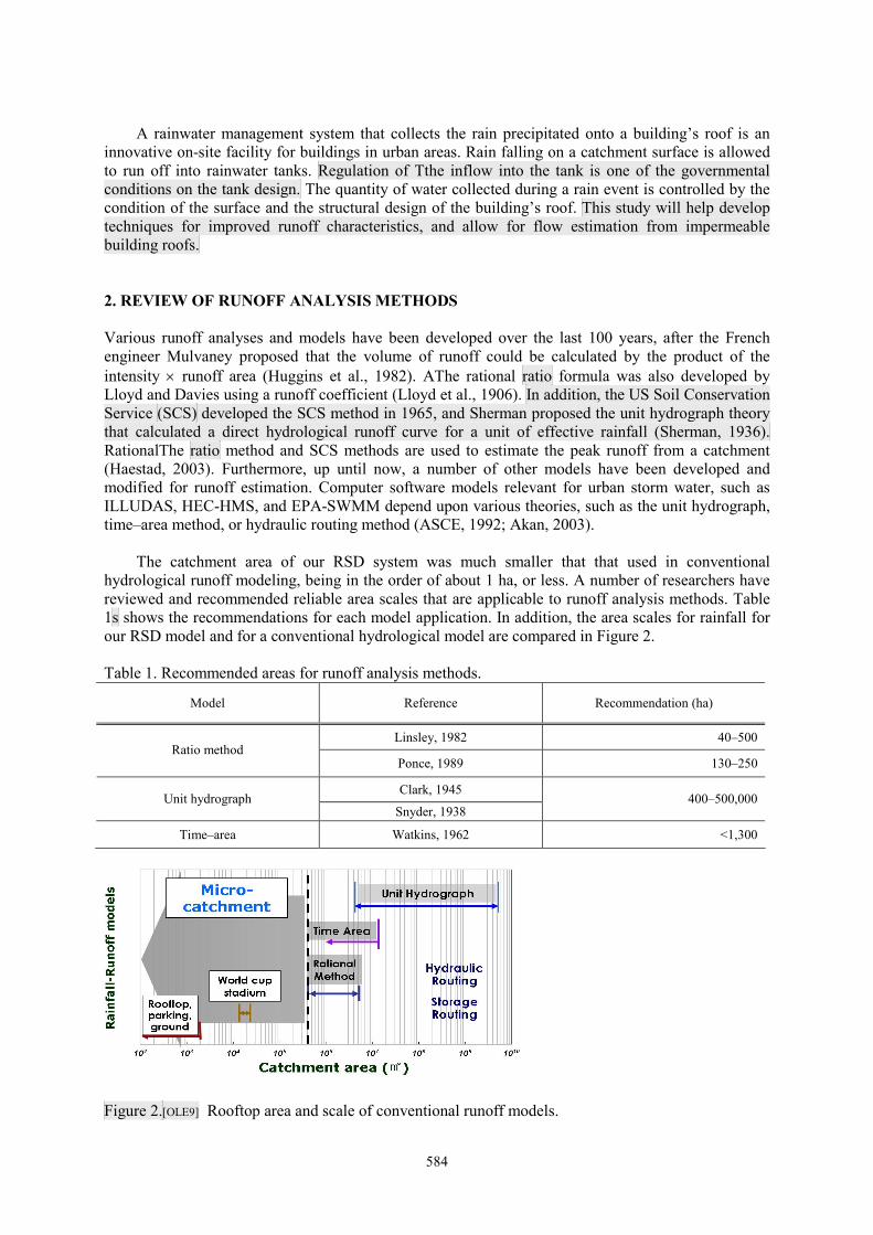
The catchment area of our RSD system was much smaller that that used in conventional
hydrological runoff modeling, being in the order of about 1 ha, or less. A number of researchers have
reviewed and recommended reliable area scales that are applicable to runoff analysis methods. Table
1s shows the recommendations for each model application. In addition, the area scales for rainfall for
our RSD model and for a conventional hydrological model are compared in Figure 2.
Table 1. Recommended areas for runoff analysis methods.
Model Reference Recommendation (ha)
Linsley, 1982 40–500 Ratio method
Ponce, 1989 130–250
Clark, 1945 Unit hydrograph
Snyder, 1938 400–500,000
Time–area Watkins, 1962 <1,300
Figure 2.[OLE9] Rooftop area and scale of conventional runoff models.
585
According to the data shown in Table 1 and Figure 2, using a conventional model for estimation
of runoff from a rooftop would not be reasonable for the scale of a building rooftop.
3. RUNOFF CONDITIONS OF A ROOF AND THE RUNOFF EQUATION
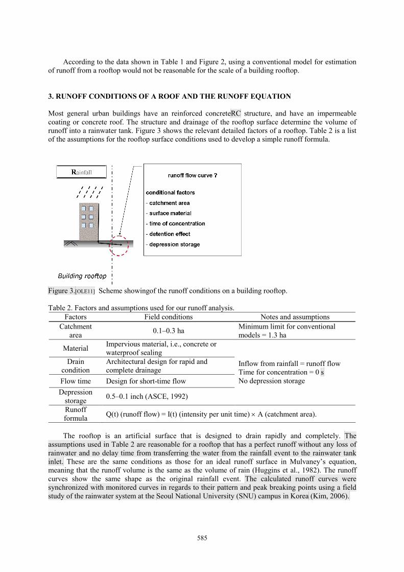
Most general urban buildings have an reinforced concreteRC structure, and have an impermeable
coating or concrete roof. The structure and drainage of the rooftop surface determine the volume of
runoff into a rainwater tank. Figure 3 shows the relevant detailed factors of a rooftop. Table 2 is a list
of the assumptions for the rooftop surface conditions used to develop a simple runoff formula.
Figure 3.[OLE11] Scheme showingof the runoff conditions on a building rooftop.
Table 2. Factors and assumptions used for our runoff analysis.
Factors Field conditions Notes and assumptions
Catchment
area 0.1–0.3 ha
Minimum limit for conventional
models = 1.3 ha
Material Impervious material, i.e., concrete or
waterproof sealing
Drain
condition
Architectural design for rapid and
complete drainage
Flow time Design for short-time flow
Depression
storage 0.5–0.1 inch (ASCE, 1992)
Inflow from rainfall = runoff flow
Time for concentration = 0 s
No depression storage
Runoff
formula Q(t) (runoff flow) = I(t) (intensity per unit time) × A (catchment area).
The rooftop is an artificial surface that is designed to drain rapidly and completely. The
assumptions used in Table 2 are reasonable for a rooftop that has a perfect runoff without any loss of
rainwater and no delay time from transferring the water from the rainfall event to the rainwater tank
inlet. These are the same conditions as those for an ideal runoff surface in Mulvaney’s equation,
meaning that the runoff volume is the same as the volume of rain (Huggins et al., 1982). The runoff
curves show the same shape as the original rainfall event. The calculated runoff curves were
synchronized with monitored curves in regards to their pattern and peak breaking points using a field
study of the rainwater system at the Seoul National University (SNU) campus in Korea (Kim, 2006).

586
4. FIELD EXPERIENCE SITES FOR VERIFICATION OF THE RUNOFF EQUATION
We monitored real rainfall and its real runoff flow from a real rainfall catchment roof located at the
Seoul National University Automatic Weathering Station (AWS) (KMA, 2004). This station
continuously measures the depth of daily rainfall, and the runoff flow is monitored from two real
rainwater systems at the SNU: athe 39-dong[OLE16] building #39 and a graduate school dormitory
building. The AWS data were representative of the rainfall on the roofs in the selected area, as the two
real systems are located within an area of 13 km2 with the SNU AWS at the center. The World
Meteorological Organization (WMO) recommends one rainfall gauge per 100–250 km2 in
mountainous areas. Figure 4 shows a schematic diagram of the two rainwater systems.
(a) The dormitory building system. (b)[OLE17] The 39-dong building #39
system.
Figure 4. Real rainwater system sitesThe dormitory inat the SNU.
The dormitory complex has a 200-ton rainwater storage tank for toilet and gardening water use,
which was constructed in November 2003 (Han et al., 2006). The rainwater from the three buildings’
roofs with an area of 2,098 m2 has been harvested and used successfully without serious failure or any
complaints from the residents. Figure 4(a) shows a schematic diagram of the structure of the system.
In this system, the runoff flow is measured using a sonic water level located in a V-notch weir. In the
39-dong building #39 at the SNU, a 250-ton dual tank system stores rainwater from a catchment area
consisting of the building roof area of 2,828 m2 and a terrace with an area of 824 m
2. The water
harvested by this system supplies the toilets in the building. Figure 4(b) shows a schematic layout of
the system (Mun et al., 2006; 2007). The water flow and consumption is monitored using on-line
automatic sensors and a data acquisition system. The volume captured by the building rooftop at this
site is monitored using a floating water level meter in the main tank.
5. ANALYSIS OF THE RUNOFF FROM THE ROOF
Figure 5 shows the cumulative runoff volume curves of the measured and estimated volumes using
Mulvaney’s equation for the dormitory building at the SNU. The estimated runoff flow was calculated
from the measured rainfall data, which were actual runoff data collected by the rainwater system at the
site. The cumulative runoff values at the time of the peak runoff and the total runoff were analyzed,
because the goal of an optimized rainwater tank design is to identify a reasonable rainwater system for
on-site peak runoff control. Table 38 shows the output of the runoff characteristics from the dormitory
building field data.

587
Figure 5.[OLE20] Cumulative runoff flow from the dormitory building roof.
Table 3. Runoff from the dormitory building roof.
Date 19 April 2005 6 May 2005
Time point Peak time Total Peak time Total
Measured volume (M, m3) 17.6 27.9 33.1 45.8
Estimated volume (E, m3) 20.2 34.6 37.8 44.8
Ratio (M/E) 0.88 0.81 0.87 1.02
The shapes of the measured and estimated curves were concurrent. Although the ratio of M/E was
similar to the value of the runoff coefficient for a concrete surface, 0.85–0.95 (Maidment, 1992), the
ratio of M/E is only a simple flow quantity value, that is different from and depends on the different
runoff coefficients concept of that input into the ratio theoryformula. In addition, the total volume on
6 May for the measured and the estimated cases was almost the same. This means that our estimated
method was reasonable in the case of runoff from a microcatchment area.
Figure 6 and Table 4 show the runoff data from the 39-dong building #39 rainfall catchment area.

588
Figure 6.[OLE22] The cumulative runoff flow from the building # 39-dong building roof.
The catchment area of the 39-dong building #39 was onl0y 960 m2, which is less than half that of
the dormitory building area of 2,098 m2. The ratio of M/E was higher than that of the dormitory
building.

589
Table 4. Runoff from the building #39-dong building roof.
Date 29 June 2006 10 July 2006
Time point Peak time Total Peak time Total
Measured volume (M, m3) 4.46 7.71 5.22 6.64
Estimated volume (E, m3) 4.76 8.31 5.75 7.60
Ratio (M/E) 0.93 0.93 0.90 0.87
From this field study on the runoff from rooftops, Mulvaney’s equation is reliable in the case of a
microcatchment runoff analysis for the design of an RSD system.
6. CONCLUSIONS AND DISCUSSION
Waterproof-coated or concrete surface building roofs have almost ideal runoff conditions in a
hydrologic runoff analysis. The runoff flow follows the rainfall intensity pattern with time. In this
study, we assumed that a rooftop surface was a perfect drain area without any loss or retention.[OLE23]
There was a small difference of about 0.05%–0.2% in the total volume of measured and estimated
runoff. This lost volume of water is due to leakage from pipes or depression storage on the roof’s
surface. A small error in the estimated values would not be serious in tank design, because the result
would be an underestimation of the real flow.
From the results of this study of field experience, Mulvaney’s equation for runoff analysis is a
reliable method for calculating runoff flow from a building roof area. This means that we can
determine a design using hydrologic inflow curves for rainwater tanks in RSD systems using this
equation. ThisOur method is reasonable only in the case of an impermeable catchment area below 1 ha,
such as a concrete rooftop. Thus, larger-scale RSD systems require further studies to determine their
properties.
ACKNOWLEDGEMENT
This research was supported by a grant (06ConstructionCoreB02) from Construction Core Technology
Program funded by Ministry of Construction & Transportation of Korean government and by Safe and
Sustainable Infrastructure Research Group.
REFERENCES
American Society of Civil Engineers (ASCE), 1992, Design and Construction of Urban Stormwater
Management System, ASCE Manuals and Reports of Engineering Practice No.77
C.T.Haan, H.P.Johnson, D.L.Brakensiek, 1982, Hydrologic modeling of small watersheds
Haestad Durrans, 2003, Stormwater conveyance modeling and design, Haestad Methods, Inc.
Huggins,L.F., Burney, J.R.,1982, Surface runoff, storage and routing, Hydrologic Modeling of
Small Watersheds
Kim.Y.J., Han M.Y., Kim.Y.H., 2006, A study on the rainwater tank design in RSR system for
urban drain capacity improvement, Proceedings of Korean Society of Water and Wastewater
and of Water Quality Conference, Vol.1. pp.601-622.
C.T.Haan, H.P.Johnson, D.L.Brakensiek, 1982, Hydrologic modeling of small watersheds
Haestad Durrans, 2003, Stormwater conveyance modeling and design, Haestad Methods, Inc.

590
Huggins,L.F., Burney, J.R.,1982, Surface runoff, storage and routing, Hydrologic Modeling of
Small Watersheds
Maidment, David R., 1992, Handbook of Hydrology, McGraw-Hill
McCarthy, G.T., 1939, The Unit hydrograph and Flood Routing, Army Engineer District,
Providence, RI, USA