Analysis of Overvoltages on Power Transformer Recorded by ... · transformer winding, resonance...
9
Analysis of Overvoltages on Power Transformer Recorded by Transient Overvoltage Monitoring System B. Filipovic-Grcic 1 , B. Jurisic 2 , S. Keitoue 2 , I. Murat 2 , D. Filipovic-Grcic 2 , A. Zupan 3 1 University of Zagreb, Faculty of Electrical Engineering and Computing, Zagreb, Croatia 2 Končar - Electrical Engineering Institute Inc., Zagreb, Croatia 3 Croatian Transmission System Operator Ltd., Kupska 4, Zagreb, Croatia E-mail: [email protected] Abstract—In this paper, an on-line transient overvoltage monitoring system (TOMS) for power transformers is used for measurement of overvoltages on the transformer bushing tap. The focus of the paper is on the analysis of transient overvoltages caused by lightning strikes recorded at the terminals of power transformer. Several recorded overvoltages are analyzed and their amplitudes and frequency spectrum are presented and compared with those referring to standard impulse voltages from IEC standard. Collected data include number, peak and duration of recorded transient overvoltages and can be used for the assessment of the transformer insulation condition and estimation of health index. Data recorded by TOMS are also of significant importance since the insulation system of power transformer and other equipment in the substation can be damaged by lightning or switching overvoltages. Index Terms— monitoring system, power transformer, lightning overvoltages, frequency spectrum, insulation. I. INTRODUCTION Power transformers are subjected to various transients often caused by lightning or switching operations. Transformer insulation is tested with the standard lighting and switching impulses in high voltage laboratory. However, in the operation various non-standard waveforms stress insulation. Front and tail time of the overvoltages at transformer terminals measured in operation differ from the standard ones, and the waveshapes can be oscillatory contrary to the standard unidirectional double exponentials [1]. Standard lightning impulse and switching impulse test voltages have been questioned as they should be based on the actual overvoltages measured in service [2, 3] which can be acquired via appropriate monitoring system. Many investigations have been carried out to study the electric aging of oil-paper insulation, including the research on the accumulative effect of repeated lightning impulses in power transformers [4-11]. The work presented in [11] reveals that the accumulation of repeated lightning impulses may lead to the breakdown of insulation and thus threaten the safe operation of power system. Although many studies have been focused on the influence of accumulative effect, the basic mechanism still has not been clearly clarified, hence it’s necessary to study the influence of accumulative effect on property of oil impregnated paper (OIP) insulation and explore its mechanisms. In [12], the research shows significant influence of repeated lightning impulses on OIP samples and confirmed the existence of accumulative effect. The repeated application of lightning impulses will weaken performance of OIP insulation and could eventually lead to breakdown. During the tests, translucent gelatinous substance was detected and the colour of OIP changed on the sample surface, which can be attributed to the variation of cellulose paper itself. With the accumulation of repeated lightning impulses, the dielectric parameters of OIP increase significantly in the lower frequency range, including relative permittivity, volume conductivity and dielectric loss angle. The generation of polar products and translucent gelatinous substance on the sample surface and the variation of cellulose fiber itself are the main factors. In [13], statistics of amplitudes and time parameters of the intrusive lightning overvoltages into the substation have been investigated based on the measured data, which were monitored at the HV bushings of the power transformers in a 110 kV air-insulated substation. Measured data indicated bidirectional oscillatory lightning waveforms. Considering the lightning stroke characteristics, structure of power system and observation conditions, the majority of induced lightning surges, the surge arresters, and the winding resonance in the transformer, resulted in the relatively long time parameters of the recorded overvoltages on transformers. For the front time and tail time obtained in [13], the 50% values of the cumulative frequency are 20.8 and 198 μs, respectively. In real operating conditions, lightning overvoltage at transformer terminals can be an oscillatory waveform, due to multiple reflections at the points where the impedance significantly changed. It is important to know the frequency spectrum of lightning overvoltages at transformer terminals, since in case when dominant frequency of lightning overvoltage is close to the natural frequency of the transformer winding, resonance overvoltages can occur. These overvotages may cause transformer failure, such as the cases of transformer failures described in [14]. In this paper, an on-line TOMS for power transformers is presented. Overvoltages are measured on the transformer bushing tap. The focus of the paper is on the analysis of transient overvoltages caused by lightning strikes recorded at
Transcript of Analysis of Overvoltages on Power Transformer Recorded by ... · transformer winding, resonance...

Analysis of Overvoltages on Power Transformer
Recorded by Transient Overvoltage Monitoring
System B. Filipovic-Grcic1, B. Jurisic2, S. Keitoue2, I. Murat2, D. Filipovic-Grcic2, A. Zupan3
1University of Zagreb, Faculty of Electrical Engineering and Computing, Zagreb, Croatia 2Končar - Electrical Engineering Institute Inc., Zagreb, Croatia
3Croatian Transmission System Operator Ltd., Kupska 4, Zagreb, Croatia
E-mail: [email protected]
Abstract—In this paper, an on-line transient overvoltage monitoring system (TOMS) for power transformers is used for
measurement of overvoltages on the transformer bushing tap. The focus of the paper is on the analysis of transient
overvoltages caused by lightning strikes recorded at the terminals of power transformer. Several recorded overvoltages are
analyzed and their amplitudes and frequency spectrum are presented and compared with those referring to standard impulse
voltages from IEC standard. Collected data include number, peak and duration of recorded transient overvoltages and can
be used for the assessment of the transformer insulation condition and estimation of health index. Data recorded by TOMS
are also of significant importance since the insulation system of power transformer and other equipment in the substation can
be damaged by lightning or switching overvoltages.
Index Terms— monitoring system, power transformer, lightning overvoltages, frequency spectrum, insulation.
I. INTRODUCTION
Power transformers are subjected to various transients often caused by lightning or switching operations. Transformer
insulation is tested with the standard lighting and switching impulses in high voltage laboratory. However, in the
operation various non-standard waveforms stress insulation. Front and tail time of the overvoltages at transformer
terminals measured in operation differ from the standard ones, and the waveshapes can be oscillatory contrary to the
standard unidirectional double exponentials [1]. Standard lightning impulse and switching impulse test voltages have
been questioned as they should be based on the actual overvoltages measured in service [2, 3] which can be acquired via
appropriate monitoring system.
Many investigations have been carried out to study the electric aging of oil-paper insulation, including the research on
the accumulative effect of repeated lightning impulses in power transformers [4-11]. The work presented in [11] reveals
that the accumulation of repeated lightning impulses may lead to the breakdown of insulation and thus threaten the safe
operation of power system. Although many studies have been focused on the influence of accumulative effect, the basic
mechanism still has not been clearly clarified, hence it’s necessary to study the influence of accumulative effect on
property of oil impregnated paper (OIP) insulation and explore its mechanisms. In [12], the research shows significant
influence of repeated lightning impulses on OIP samples and confirmed the existence of accumulative effect. The
repeated application of lightning impulses will weaken performance of OIP insulation and could eventually lead to
breakdown. During the tests, translucent gelatinous substance was detected and the colour of OIP changed on the
sample surface, which can be attributed to the variation of cellulose paper itself. With the accumulation of repeated
lightning impulses, the dielectric parameters of OIP increase significantly in the lower frequency range, including
relative permittivity, volume conductivity and dielectric loss angle. The generation of polar products and translucent
gelatinous substance on the sample surface and the variation of cellulose fiber itself are the main factors.
In [13], statistics of amplitudes and time parameters of the intrusive lightning overvoltages into the substation have been
investigated based on the measured data, which were monitored at the HV bushings of the power transformers in a
110 kV air-insulated substation. Measured data indicated bidirectional oscillatory lightning waveforms. Considering the
lightning stroke characteristics, structure of power system and observation conditions, the majority of induced lightning
surges, the surge arresters, and the winding resonance in the transformer, resulted in the relatively long time parameters
of the recorded overvoltages on transformers. For the front time and tail time obtained in [13], the 50% values of the
cumulative frequency are 20.8 and 198 μs, respectively. In real operating conditions, lightning overvoltage at
transformer terminals can be an oscillatory waveform, due to multiple reflections at the points where the impedance
significantly changed. It is important to know the frequency spectrum of lightning overvoltages at transformer
terminals, since in case when dominant frequency of lightning overvoltage is close to the natural frequency of the
transformer winding, resonance overvoltages can occur. These overvotages may cause transformer failure, such as the
cases of transformer failures described in [14].
In this paper, an on-line TOMS for power transformers is presented. Overvoltages are measured on the transformer
bushing tap. The focus of the paper is on the analysis of transient overvoltages caused by lightning strikes recorded at
the terminals of power transformer. To determine the origin of the recorded transient overvoltages, data from TOMS are
correlated with data from the lightning location system (LLS) and SCADA system. Several recorded overvoltages are
analysed and their frequency spectrum is presented and compared with those referring to the standard impulse voltages
from the IEC standard [16]. Collected data include number, peak and duration of recorded transient overvoltages and
can be used as the basis for the assessment of the transformer insulation condition and estimation of health index. Data
recorded by TOMS are also of significant importance since the insulation system of power transformer and other
equipment in the substation can be damaged by lightning or switching overvoltages.
II. ON-LINE TRANSIENT OVERVOLTAGE MONITORING SYSTEM
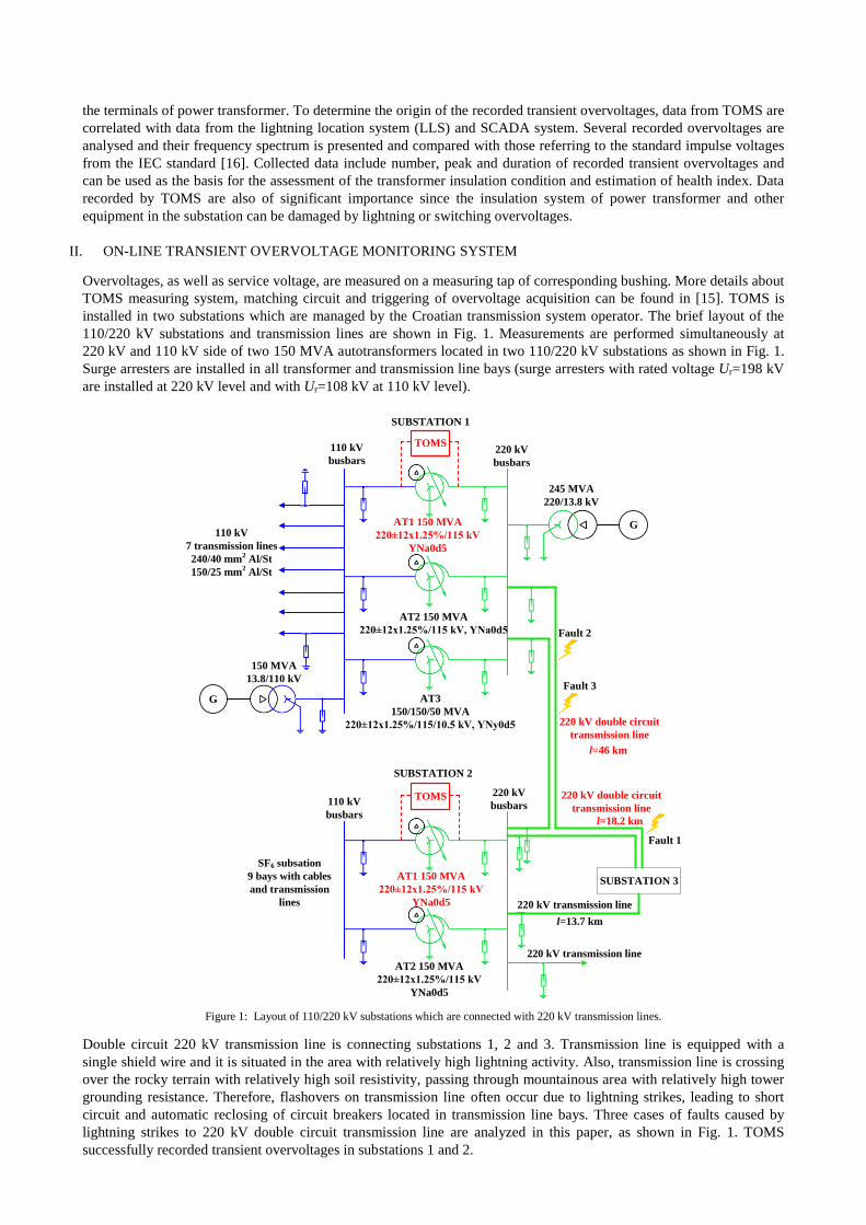
Overvoltages, as well as service voltage, are measured on a measuring tap of corresponding bushing. More details about
TOMS measuring system, matching circuit and triggering of overvoltage acquisition can be found in [15]. TOMS is
installed in two substations which are managed by the Croatian transmission system operator. The brief layout of the
110/220 kV substations and transmission lines are shown in Fig. 1. Measurements are performed simultaneously at
220 kV and 110 kV side of two 150 MVA autotransformers located in two 110/220 kV substations as shown in Fig. 1.
Surge arresters are installed in all transformer and transmission line bays (surge arresters with rated voltage Ur=198 kV
are installed at 220 kV level and with Ur=108 kV at 110 kV level).
G
245 MVA
220/13.8 kV
AT1 150 MVA
220±12x1.25%/115 kV
YNa0d5
AT2 150 MVA
220±12x1.25%/115 kV, YNa0d5
AT3
150/150/50 MVA
220±12x1.25%/115/10.5 kV, YNy0d5
TOMS220 kV
busbars
110 kV
busbars
110 kV
7 transmission lines
240/40 mm2 Al/St
150/25 mm2 Al/St
G
150 MVA
13.8/110 kV
220 kV double circuit
transmission line
AT1 150 MVA
220±12x1.25%/115 kV
YNa0d5
AT2 150 MVA
220±12x1.25%/115 kV
YNa0d5
TOMS 220 kV
busbars110 kV
busbars
SF6 subsation
9 bays with cables
and transmission
lines 220 kV transmission line
SUBSTATION 1
SUBSTATION 2
SUBSTATION 3
l=46 km
220 kV double circuit
transmission line
l=18.2 km
l=13.7 km
Fault 1
Fault 2
Fault 3
220 kV transmission line
Figure 1: Layout of 110/220 kV substations which are connected with 220 kV transmission lines.
Double circuit 220 kV transmission line is connecting substations 1, 2 and 3. Transmission line is equipped with a
single shield wire and it is situated in the area with relatively high lightning activity. Also, transmission line is crossing
over the rocky terrain with relatively high soil resistivity, passing through mountainous area with relatively high tower
grounding resistance. Therefore, flashovers on transmission line often occur due to lightning strikes, leading to short
circuit and automatic reclosing of circuit breakers located in transmission line bays. Three cases of faults caused by
lightning strikes to 220 kV double circuit transmission line are analyzed in this paper, as shown in Fig. 1. TOMS
successfully recorded transient overvoltages in substations 1 and 2.

III. LIGHTNING LOCATION SYSTEM
At the end of 2008, a LLS was established as part of the LINET network, covering a wide area of the Croatian territory.
LINET is a modern LLS with a network of more than 125 sensors covering most of Europe. LLS measures the VLF/LF
frequency spectrum of electromagnetic waves which lightning strikes emit. The measurement of magnetic flux is
carried out through highly sensitive sensors which are arranged across the area with spacing of around 150 to 250 km.
Since the electromagnetic emission of the lightning spreads at the speed of light, it reaches the sensors at different
points in time. Although the difference is in the order of micro-seconds, the relatively accurate calculation of the
original emission location of the lightning strike is possible. The data measured by every single sensor is transmitted to
a central server. The exact geographical position for all the lightning strikes measured is calculated and stored in a
database. This measurement method is also known as the “time-of-arrival” method. Application of LLS in power
system control of Croatian transmission system operator enables lightning activity tracking and time-spatial correlation
with incidences (faults, automatic re-closures, outages) registered by the relay protection system [15].
IV. TRANSIENT OVERVOLTAGES RECORDED ON POWER TRANSFORMERS
Overvoltages in power network can be caused by lightning strikes to overhead transmission lines, circuit breaker
switching operations and faults. Power transformers can be exposed to such transient overvoltages during the operation.
Transient overvoltages with steep wave front have an impact on dielectric stresses of the insulation of the first few
winding turns or in the case of the resonance voltage built up locally inside the winding. The number and amplitudes of
overvoltages which stress the insulation depend on various parameters such as the lightning strike density in the
considered area, since it determines how often the transformer is stressed by lightning overvoltages. Since the
overvoltage amplitudes at transformer terminals are usually unknown, an on-line overvoltage transient recorder is used
with the ability to sample, analyze and store transients in real-time. Three cases of faults (Fig. 1) caused by lightning
strikes are analysed in more detail to investigate amplitude and frequency characteristics of lightning overvoltages
recorded at power transformer terminals.
A. Case 1 - lightning strike to 220 kV transmission line connecting substations 2 and 3 causing insulator
flashover in two phases
Transients recorded by TOMS installed in substations 1 and 2 are shown in Figs. 2 and 3. The recorded transients were
time-correlated with a lightning strike which was detected by LLS. Lightning strike with current amplitude 115 kA
occurred hit tower of 220 kV transmission line connecting substations 2 and 3, at a distance of 11.2 km from substation
2 (7 km from substation 3). At the same time, SCADA system detected double phase to ground fault in phases A and C,
following the auto-reclosure operation of circuit breakers in the line bays in substations 2 and 3. Although substation 2
is closer to the fault location compared to substation 1, overvoltages in substation 2 are lower due to network topology
and reflections of traveling waves, coming simultaneously from both circuits of transmission line (induced and direct
overvoltages) and entering substation 1.
Figure 2: Transient overvoltages recorded in substation 1.
Figure 3: Transient overvoltages recorded in substation 2.
It is possible to extract the transient overvoltage waveforms from the recorder data using the high-pass FIR filter. High-
pass filter is used to obtain only high-frequency components caused by lightning overvoltages and to remove low-
frequency and power frequency components from measured waveforms. Lightning overvoltage waveforms obtained
after filtering out low frequency components from measurements are shown in Figs. 4 and 5. Waveforms from Figs. 4
and 5 were transformed to the frequency domain using the fast Fourier transform (FFT) and calculated frequency
spectrum is shown in Figs. 6 and 7.

Figure 4: Lightning overvoltages recorded in substation 1 (after filtering
out low frequency components).
Figure 5: Lightning overvoltages recorded in substation 2 (after filtering
out low frequency components).
Figure 6: Frequency spectrum of lightning overvoltages recorded in
substation 1.
Figure 7: Frequency spectrum of lightning overvoltages recorded in
substation 2.
B. Case 2 - lightning strike to 220 kV transmission line connecting substations 1 and 2 causing insulator
flashover in two phases
Transients recorded by TOMS in substations 1 and 2 are shown in Figs. 8 and 9.
Figure 8: Transient overvoltages recorded in substation 1.
Figure 9: Transient overvoltages recorded in substation 2.
Recorded transients were time-correlated with a lightning strike which was detected by LLS. Lightning strike with
current amplitude -75.3 kA occurred on the 220 kV transmission line connecting substations 1 and 2 at a distance of
2.9 km from the substation 1. At the same time, SCADA system detected double phase to ground fault in phases A and
B, following the auto-reclosure operation of circuit breakers in the line bays in substation 1 and 2. Transient
overvoltages after filtering out low frequency components and their frequency spectrum is shown in Figs. 10-13.

Figure 10: Lightning overvoltages recorded in substation 1 (after filtering out
low frequency components).
Figure 11: Lightning overvoltages recorded in substation 2 (after
filtering out low frequency components).
Figure 12: Frequency spectrum of lightning overvoltages recorded in
substation 1.
Figure 13: Frequency spectrum of lightning overvoltages recorded
in substation 2.
C. Case 3 – multiple lightning strike to 220 kV transmission line connecting substations 1 and 2 causing
insulator flashover in three phases
Another interesting event recorded by TOMS was caused by multiple lightning strike which occurred on the 220 kV
transmission line route, at a distance of 16 km from the substation 1 (30 km from substation 2). Parameters of multiple
lightning strikes are given in Table I. Recorded transients were time-correlated with a lightning flash consisting of
seven subsequent lightning strikes which were detected by LLS. Three lightning strikes marked in Table I were selected
as the ones that probably caused recorded transients. This was done by matching the time difference between the
successive lightning strikes detected by LLS with the time difference between the events recorded by TOMS.
TABLE I. PARAMETERS OF MULTIPLE LIGHTNING STRIKES DETECTED BY LLS
Lightning strike
number
Time
(h:min:sec.milisec)
Lightning current
amplitude (kA)
Time difference between
subsequent lightning strikes Δt (ms)
1 01:02:12.257 15.5 -
2 01:02:12.261 -80.2 4
3 01:02:12.274 -20 13
4 01:02:12.293 -8 19
5 01:02:12.294 -30.3 1
6 01:02:12.306 -19 12
7 01:02:12.319 -12.7 13
Transients recorded by TOMS which were caused by strike no. 2 (current amplitude -80.2 kA) and corresponding
frequency spectrums are shown in Figs. 14-19. At the same time, SCADA system detected line to ground fault in all
phases, following the auto-reclosure operation of circuit breakers in the line bays in substations 1 and 2. Circuit
breakers interrupted short-circuit current firstly in substation 2. While short-circuit current was still supplied from
substation 1, two successive lightning strikes 13 ms apart (no. 6 and 7 from Table I) hit transmission line, and
overvoltages were recorded by TOMS at power transformer terminals in substation 1 (Figs. 20 and 21). These two
lightning overvoltages can be clearly seen in Fig. 20, while at the end of recording (around 25 ms) switching
overvoltages occur due to opening of circuit breaker in substation 1.

Figure 14: Transient overvoltages recorded in substation 1.
Figure 15: Transient overvoltages recorded in substation 2.
Figure 16: Lightning overvoltages recorded in substation 1 (after filtering
out low frequency components).
Figure 17: Lightning overvoltages recorded in substation 2 (after
filtering out low frequency components).
Figure 18: Frequency spectrum of lightning overvoltages recorded in
substation 1.
Figure 19: Frequency spectrum of lightning overvoltages recorded
in substation 2.
Figure 20: Transient overvoltages recorded in substation 1 (continued).
Figure 21: Frequency spectrum of lightning overvoltages recorded
in substation 1 (continued).
13 ms

V. DISCUSSION AND FUTURE WORK
The wide variety of lightning stroke characteristics and the modifying effects of power system components result in a
diversity of intrusive lightning voltage waveshapes that stress transformers. These are not the traditional standard
lightning impulses with a waveshape of 1.2/50 μs which are used according to IEC [16]. Therefore, the applicability of
the standard lightning impulse voltage to power transformer testing has been questioned, and the overvoltage used in
the test on transformers should be as close as possible to the lightning overvoltages measured in service [13].
Analysis of measurement results indicated that bidirectional oscillatory overvoltage waveforms caused by lightning
strikes appear at terminals of power transformer. Oscillatory character of recorded overvoltages is caused by multiple
reflections of travelling waves in the substations and at the points where the system impedance significantly changed.
Considering the lightning strike characteristics, structure of power system and observation conditions, the operation of
surge arresters in transformer and line bays, and the winding resonance in the transformer, resulted in the relatively
long-time parameters of overvoltages recorded on power transformers. Recorded lightning overvoltages are
bidirectional oscillatory with duration of several milliseconds (5-6 ms), which is quite different from standard lightning
impulse waveform used for testing of power transformers. Maximum recorded amplitude of overvoltages is 371 kV
(Fig. 10) causing the operation of surge arresters installed in line and transformer bay.
It is also important to investigate the frequency spectrum of lightning overvoltages at transformer terminals, since in
case when dominant frequency of overvoltage is close to the natural frequency of the transformer winding, resonance
overvoltages can occur which in some cases may cause transformer failure. FFT analysis of recorded overvoltages
showed that dominant frequency components are in range 1-30 kHz. Frequency spectrum of measured overvoltages
differs from the frequency spectrum of standard impulse waveforms. Fig. 22 shows comparison between spectral
densities of measured overvoltage (from case 2, Fig. 10, phase A) and standard lightning impulse waveform 1.2/50 μs
with amplitude 1050 kV. According to the method described in [18], Frequency Domain Severity Factor (FDSF) can be
determined which is defined as the ratio between the spectral density of the measured overvoltage and the spectral
density of the standard lightning waveform used for testing transformers. It considers the frequency content of the
overvoltages measured in the substation and compares it to the frequency content of voltage waveforms for which the
transformer had been tested. The FDSF factor should be less than 1 to ensure that the stresses arising from a particular
event occurring in the system will be adequately covered by dielectric tests performed in the HV laboratory.
Figure 22: Spectral density of measured overvoltage and standard
lightning impulse waveform 1.2/50 μs, 1050 kV.
Figure 23: FSDF of measured overvoltage versus frequency.
Fig. 23 shows calculated FSDF factor which was greater than 1 at frequency ranges 2.5-6.1 kHz and 9.3-10.4 kHz,
meaning that at these frequencies the highest electrical stress on the transformer insulation is expected. It also means
that transformer tests performed with lightning waveforms do not cover adequately low frequency stresses. Therefore,
overvoltages measured in a substation can excite a resonance throughout the windings of transformer which is often
found in the 5-30 kHz range. The FDSF approach can thus be used both for design review upon incoming transients and
in analysis of failures. When combined with online monitoring, it can also be used as indicator of increased transient
risks for a power transformer.
Some investigations presented in [12] and [17] show negative accumulative effect of multiple lightning impulses on
insulation properties of oil-paper insulation systems. The repeated application of lightning impulses will weaken the
insulation performance of insulation system and can eventually lead to breakdown. Lightning discharges (flashes) that
transfer to ground both positive and negative charges are termed bipolar lightning discharges. In case 3 presented in the
previous section, bipolar lightning flash consisting of seven subsequent lightning strikes caused transient overvoltages
on power transformer terminals. As can be seen from this case, time difference between subsequent lightning strikes
varies from 1 ms to 19 ms. Therefore, in a relatively short time period multiple transient overvoltages of different

polarity may occur on transformer terminals. Experimental investigations confirm that degradation of transformer
insulation system increases significantly as time difference between successive transient overvoltages decrease.
Therefore, it is very important to measure transient overvoltages on transformer terminals and to record such events in
order to assess an overall condition of transformer insulation system and to include this effect in estimation of health
index. The future investigations will consider:
- Automatic grouping of overvoltage types (temporary, switching, lightning) based on correlation with SCADA
and LLS.
- Statistical analysis of amplitudes, frequency spectrum and FDSF based on a larger number of transient
overvoltages registered on a power transformer (for example data collected over several years).
- Comparison of the measured oscillatory non-standard voltage waveforms with the standard one using energy
method in which oscillatory waveforms are equivalented by double exponential waveforms with the same
energy. Afterwards, front time, crest voltage and tail time of equivalent waveforms can be determined and
compared to standard impulse waveforms.
- Simulation of electromagnetic transients and comparison with measurements. Such analysis can be used for
example for validation of high-frequency power transformer models or to study the interaction between power
transformers and network.
- Development of method for assessment of the transformer insulation degradation caused by transient
overvoltages based on measured data from TOMS. This will be used for estimation of power transformer
health index.
- Use an existing TOMS for measurement of transient currents through station surge arresters caused by
lightning or switching overvoltages. This will enable to determine energy stress of station arresters directly
from measurements.
VI. CONCLUSIONS
In this paper, an on-line transient overvoltage monitoring system for power transformers is used for measurement of
overvoltages on the transformer bushing tap. The focus of the paper is on the analysis of transient overvoltages caused
by lightning strikes recorded at the terminals of power transformer. Three cases of faults caused by lightning strikes to
220 kV double circuit transmission line are presented. Measured overvoltages and faults were corelated with SCADA
system and LLS data.
Recorded lightning overvoltages are bidirectional oscillatory with duration of several milliseconds, which is quite
different from standard lightning impulse waveforms used for testing of power transformers. FFT analysis of recorded
overvoltages showed that dominant frequency components are in range 1-30 kHz. Frequency spectrum of measured
overvoltages differs from the frequency spectrum of standard lightning impulse waveforms. Analysis of FSDF factor
showed that transformer tests performed with lightning waveforms do not cover adequately low frequency phenomena
which are present in recorded overvoltages.
Bipolar lightning flash consisting of seven subsequent lightning strikes caused transient overvoltages on power
transformer terminals. Therefore, in a relatively short time period multiple transient overvoltages of different polarity
may occur on transformer terminals. Experimental investigations confirm that degradation of transformer insulation
system increases significantly as time difference between successive transient overvoltages decrease. Therefore, it is
very important to measure transient overvoltages on transformer terminals and to record such events in order to assess
an overall condition of transformer insulation system and to include this effect in estimation of health index.
VII. REFERENCES
[1] Darveniza, M.: ‘The generalized integration method for predicting impulse volt-time characteristics for non-standard wave shapes-a theoretical
basis’, IEEE Trans. Electr. Insul., 1988, 23, (3), pp. 373–381.
[2] Okabe, S., Takami, J.: ‘Evaluation of breakdown characteristics of oil-immersed transformers under non-standard lightning impulse waveforms – method for converting non-standard lightning impulse waveforms into standard lightning impulse waveforms’, IEEE Trans. Dielectr. Electr.
Insul., 2008, 15, (5), pp. 1288–1296.
[3] Berlijn, S., Garnacho, F., Gockenbach, E.: ‘Today’s problems with the evaluation methods of full lightning impulse parameters as described in engineering’. Proc. Int. Conf. High-Voltage Engineering, London, UK, 1999, pp. 49–52.
[4] W. G. Standring and R. C. Hughes, "Breakdown under impulse voltages of solid and liquid dielectrics in combination," IEE Proc. Power Eng.,
Vol. 103, pp. 583-597, 1956. [5] Q. Liu and Z. D. Wang, "Streamer characteristic and breakdown in synthetic and natural éster transformer liquids under standard lightning
impulse voltage," IEEE Trans. Dielectr. Electr. Insul., Vol. 18, pp. 285-294, 2011.
[6] M. Kaufhold, G. Borner, M. Eberhardt, and J. Speck, "Failure mechanism of the interturn insulation of low voltage electric machines fed by pulse-controlled inverters," IEEE Electr. Insul. Mag., Vol. 12, No.5, pp. 9-16, 1996.
[7] W. Yin, "Failure mechanism of winding insulations in inverter-fed motors," IEEE Electr. Insul. Mag., Vol. 13, No.6, pp. 18-23, 1997.

[8] J. P. Bellomo, T. Lebey, J. M. Oraison, and F. Peltier, "Electrical aging of stator insulation of low voltage rotating machines supplied by
inverters," IEEE. Int’l. Sympos. Electr. Insul., pp. 210-213, 1996.
[9] A. J. Vandermaar, M. Wang, J. B. Neilson, and K. D. Srivastava, "The electrical breakdown characteristics of oil-paper insulation under steep front impulse voltages," IEEE Trans. Power Del., Vol. 9, pp. 1926-1935, 1994.
[10] S. P. Balaji, I. P. Merin Sheema, G. Krithika and S. Usa, "Effect of Repeated Impulses on Transformer Insulation," IEEE Trans. Dielectr.
Electr. Insul., Vol. 18, pp. 2069-2073, 2011. [11] S. Okabe, "Voltage-time and voltage-number characteristics of insulation elements with oil-filled transformers in EHV and UHV classes," IEEE
Trans. Dielectr. Electr. Insul., Vol. 13, pp. 436-444, 2006.
[12] Wenxia Sima, Potao Sun, Qing Yang, Tao Yuan, Chen Lu and Ming Yang, “Study on the Accumulative Effect of Repeated Lightning Impulses on Insulation Characteristics of Transformer Oil Impregnated Paper, IEEE Transactions on Dielectrics and Electrical Insulation Vol. 21, No. 4;
August 2014.
[13] W. Sima, X. Lan, Q. Yang and T. Yuan, "Statistical analysis on measured lightning overvoltage surges in a 110 kV air-insulated substation," in IET Science, Measurement & Technology, vol. 9, no. 1, pp. 28-36, 1 2015. doi: 10.1049/iet-smt.2013.0235
[14] CIGRE Joint Working Group A2/C4.39, “Electrical Transient Interaction Between Transformers and the Power System, Part 2: Case studies”,
CIGRE brochure 577B, April 2014. [15] B. Filipović-Grčić, B. Franc, I. Uglešić, I. Pavić, S. Keitoue, I. Murat, I. Ivanković, “Monitoring of transient overvoltages on the power
transformers and shunt reactors – field experience in the Croatian power transmission system”, Procedia Engineering, vol. 202, pp. 29-42, 2017.
[16] IEC 60060–1: “High voltage test techniques, part I: General definitions and test requirements”, 2010. [17] P. Sun, W. Sima, Q. Yang, T. Yuan, X. Lan and C. Lu, "Accumulative effect of oil-paper insulation system under multiple lightning impulse
voltage," 2013 Annual Report Conference on Electrical Insulation and Dielectric Phenomena, Shenzhen, 2013, pp. 202-205.
[18] CIGRE technical brochure, “ Electrical Transient Interaction Between Transformers and the Power System, Part 1- Expertise”, Joint Working Group A2/C4.39, April 2014.