Analysis of Multipath Mitigation Techniques for Satellite ... · Supervisor Elena Simona Lohan, Dr....
176
Tampere University of Technology Analysis of Multipath Mitigation Techniques for Satellite-based Positioning Applications Citation Bhuiyan, M. Z. H. (2011). Analysis of Multipath Mitigation Techniques for Satellite-based Positioning Applications. (Tampere University of Technology. Publication; Vol. 981). Tampere University of Technology. Year 2011 Version Publisher's PDF (version of record) Link to publication TUTCRIS Portal (http://www.tut.fi/tutcris) Take down policy If you believe that this document breaches copyright, please contact [email protected], and we will remove access to the work immediately and investigate your claim. Download date:22.08.2018
-
Upload
trinhduong -
Category
Documents
-
view
227 -
download
0
Transcript of Analysis of Multipath Mitigation Techniques for Satellite ... · Supervisor Elena Simona Lohan, Dr....
Tampere University of Technology
Analysis of Multipath Mitigation Techniques for Satellite-based PositioningApplications
CitationBhuiyan, M. Z. H. (2011). Analysis of Multipath Mitigation Techniques for Satellite-based PositioningApplications. (Tampere University of Technology. Publication; Vol. 981). Tampere University of Technology.
Year2011
VersionPublisher's PDF (version of record)
Link to publicationTUTCRIS Portal (http://www.tut.fi/tutcris)
Take down policyIf you believe that this document breaches copyright, please contact [email protected], and we will remove access tothe work immediately and investigate your claim.
Download date:22.08.2018


Tampereen teknillinen yliopisto. Julkaisu 981 Tampere University of Technology. Publication 981 Mohammad Zahidul Hasan Bhuiyan Analysis of Multipath Mitigation Techniques for Satellite-based Positioning Applications Thesis for the degree of Doctor of Science in Technology to be presented with due permission for public examination and criticism in Tietotalo Building, Auditorium TB222, at Tampere University of Technology, on the 6th of September 2011, at 12 noon. Tampereen teknillinen yliopisto - Tampere University of Technology Tampere 2011
Supervisor
Elena Simona Lohan, Dr. Tech., Docent Department of Communications Engineering Tampere University of Technology Tampere, Finland
Pre-examiners
Fabio Dovis, Ph.D., Assistant Professor Department of Electronics Faculty of Information and Communication Technology Politecnico di Torino Turin, Italy
Heidi Kuusniemi, Dr. Tech. Chief Research Scientist Finnish Geodetic Institute Masala, Finland
Opponent
Gonzalo Seco Granados, Ph.D., Associate Professor Department of Telecommunications and Systems Engineering Universitat Autonoma de Barcelona Barcelona, Spain ISBN 978-952-15-2624-4 (printed) ISBN 978-952-15-2648-0 (PDF) ISSN 1459-2045

Abstract
Multipath remains a dominant source of ranging errors in any Global Naviga-
tion Satellite System (GNSS), such as the Global Positioning System (GPS)
or the developing European satellite navigation system Galileo. Multipath is
undesirable in the context of GNSS, since the reception of multipath can cre-
ate significant distortion to the shape of the correlation function used in the
time delay estimate of a Delay Locked Loop (DLL) of a navigation receiver,
leading to an error in the receiver’s position estimate. Therefore, in order
to mitigate the impact of multipath on a navigation receiver, the multipath
problem has been approached from several directions, including the develop-
ment of novel signal processing techniques. Many of these techniques rely
on modifying the tracking loop discriminator (i.e., the DLL and its enhanced
variants) in order to make it resistant to multipath, but their performance in
severe multipath scenarios is still rather limited. In this thesis, the Author
particularly addresses the challenge of overcoming the difficulties due to mul-
tipath propagation by developing several novel correlation-based multipath
mitigation techniques, ranging from simple DLL based approach to advanced
multi-correlator based solution, whichever is appropriate according to the re-
quirements of positioning applications (i.e., low-cost simpler implementation
versus better accuracy). The proposed novel multipath mitigation techniques
can be categorized into three major categories considering their implementa-
tion complexity: i. the advanced technique, which requires many correlators
and have relatively complex implementation; ii. the simple technique, which
requires only a few correlators; and iii. the combined technique, which is a
combination of two other techniques and has moderate complexity.
The proposed advanced multipath mitigation techniques include Peak Track-
ing (PT) and its variants based on 2nd order Differentiation (Diff2) and Teager
Kaiser (TK) operator, non-coherent Multipath Estimating Delay Lock Loop
(MEDLL) and Reduced Search Space Maximum Likelihood (RSSML) delay
estimator. The development of these advanced multipath mitigation tech-
i
ii ABSTRACT
niques are justified from the fact that they provide better tracking accuracy
in harsh multipath environments, for example, in urban canyons, at a cost of
increased implementation complexity. Among all these techniques, RSSML
offers the best multipath mitigation performance in moderate-to-high C/N0
scenarios, as verified by the simulations in multipath fading channels. There-
fore, RSSML along with other advanced techniques proposed in this thesis
can be considered as excellent candidates for implementation in professional
GNSS receivers, especially when the tracking accuracy is a concern.
The proposed simple multipath mitigation technique includes a Slope-
Based Multipath Estimator (SBME), which requires a-priori information about
the slope of the correlation function and an additional correlator (as compared
to a traditional DLL) to estimate the multipath error. Simulation results show
that SBME has superior multipath mitigation performance to the well-known
narrow Early-Minus-Late (nEML) DLL in tested environments.
The proposed combined techniques include a C/N0-based two-stage delay
tracker and a combined TK operator with nEML DLL. The motivation for
having a combined approach is to ensure a better tracking performance with
a reasonable implementation complexity than each single combining method
that is used to form the combined multipath mitigation technique. The C/N0-
based two-stage delay tracker offers a better tracking accuracy than its indi-
vidual counterpart in multipath channel, as validated by the simulations in
an open source TUT (Tampere University of Technology) Galileo E1 signal
simulator. It also alleviates the problem of false tracking involved in High
Resolution Correlator (HRC). Hence, the C/N0-based two-stage delay tracker
can be considered as a viable solution for legacy GNSS receivers which are
currently using nEML or HRC as their delay locked loop discriminator.
The multipath performance of all the novel and the state-of-the-art tech-
niques is analyzed for three different GNSS signals, namely legacy GPS L1
C/A signal, Galileo E1 Open Service (OS) signal and the modernized GPS
L1C signal. However, this does not restrict the applicability of these tech-
niques in the context of other GNSS signals (for example, Galileo E5 signal)
as long as they are adapted considering the signals’ auto-correlation properties.
This thesis is structured in the form of a compound, including an intro-
ductory part in the research field and a collection of eight original publications
of the Author, where the main contribution of the thesis lies.

Preface
This Ph.D. dissertation has been carried out at the Department of Commu-
nications Engineering (DCE) in Tampere University of Technology (TUT),
as part of the Tekes funded research projects “Advanced Techniques for Per-
sonal Navigation (ATENA)” and “Future GNSS Applications and Techniques
(FUGAT)”, of the Academy of Finland funded research project “Digital Sig-
nal Processing Algorithms for Indoor Positioning Systems”, of the EU FP6
research project “Galileo Receiver for Mass Market (GREAT)”, and of the
EU FP7 research project “Galileo Ready Advanced Mass Market Receiver
(GRAMMAR)”. Being a postgraduate student in Tampere Doctoral Pro-
gramme in Information Sciences and Engineering (TISE), I have been receiv-
ing funding from TISE for three consecutive years from 2009 till 2011 for my
doctoral studies along with some time-to-time conference travels. I gratefully
acknowledge the support I have been receiving from TISE during these years.
I would also like to acknowledge Academy of Finland, Tekes, European Union,
Nokia Foundation, Ulla Tuomisen Saatio and Satellite Navigation University
Network (SNUN) for their financial support at various stages of my Ph.D.
studies.
I am very much fortunate to have Dr. Tech. Elena Simona Lohan as my
supervisor. I would like to express my deepest gratitude to her for invaluable
guidance, continuous support, patience and encouragement throughout the
course of this work. I can still remember her positive encouraging words
at times when I was scared of missing a hard deadline. She is so helpful,
considerate and innovative that our group executes the work that have assigned
to us with full confidence, believing that she is always there to help us in
difficult situations. Thank you, Ma’am, for being my academic supervisor.
I would like to thank Assistant Professor Fabio Dovis from the Department
of Electronics, Politecnico di Torino, Italy and Dr. Tech. Heidi Kuusniemi
from the Finnish Geodetic Institute, Finland, the reviewers of this thesis,
for their valuable and constructive feedback and competent judgment. I also
iii

iv PREFACE
thank Associate Professor Gonzalo Seco Granados for kindly agreeing to act
as the opponent in the public defense of the dissertation.
I would like to express my sincere gratitude to Prof. Markku Renfors for
offering me a position in DCE and also for guiding me during the initial months
of my Ph.D. studies.
I thank Prof. Gerard Lachapelle for his guidance and support during my
visit in the Positioning, Location And Navigation (PLAN) group in 2007.
Also, I would like to thank all my colleagues and friends in Calgary, Canada
for their cordial help and support during my ten months stay over there.
I express my appreciation to all my present and former colleagues at
DCE for creating such a pleasant and friendly working atmosphere. In par-
ticular, I would like to thank Prof. Mikko Valkama, Dr. Tech. Abdel-
monaem Lakhzouri, Dr. Tech. Ridha Hamila, Dr. Tech. Adina Burian,
Xuan Hu, Danai Skournetou, Jie Zhang, Elina Laitinen, Heikki Hurskainen,
Farzan Samad, Najmul Islam, Alexandru Rusu Casandra, Jukka Talvitie and
Bashir Siddiqui.
Warm thanks are due to Ulla Siltaloppi, Tarja Erlaukko, Sari Kinnari
and Elina Orava for their kind help with practical matters and friendly sup-
port. Specially, I would like to mention Ulla Siltaloppi’s name for her cordial,
friendly and generous support in legal matters.
I wish to extend my heartfelt thanks to the whole Bangladeshi community
in Tampere for the enjoyable moments we spent together in numerous gather-
ings and parties. It has been a real pleasure to stay in Tampere for six years
which could not be possible without you!
In this occasion, I would like to remember my parents Md. A. Satter
Bhuiyan and Mrs. Lily Akter, who were the first mentors in my life to teach
me the value of life, education, discipline and knowledge. Perhaps they would
be the happiest persons on the Earth seeing me achieving this honor!
Finally, I would like to thank my wife Mehjabin Sultana for all her love,
affection, patience and understanding during the last five years, which I be-
lieve, have been the main motivating factors to keep me in the right track. I
dedicate this thesis to my daughter Lilya Doyeeta Bhuiyan, who redefines our
life as beautiful as it could be.
Tampere, August 2011
Mohammad Zahidul Hasan Bhuiyan
Contents
Abstract i
Preface iii
Table of Contents v
List of Publications ix
List of Abbreviations xi
List of Principal Symbols xv
List of Figures xix
1 Introduction 1
1.1 State-of-the-Art . . . . . . . . . . . . . . . . . . . . . . . . . . . 2
1.2 Scope of the Thesis . . . . . . . . . . . . . . . . . . . . . . . . . 5
1.3 Thesis Contributions . . . . . . . . . . . . . . . . . . . . . . . . 6
1.4 Thesis Outline . . . . . . . . . . . . . . . . . . . . . . . . . . . 7
2 Global Navigation Satellite Systems 9
2.1 Brief History of Satellite Navigation System . . . . . . . . . . . 9
2.2 Fundamentals of Satellite-based Positioning . . . . . . . . . . . 10
2.3 Overview of GPS . . . . . . . . . . . . . . . . . . . . . . . . . . 10
2.4 Overview of Galileo . . . . . . . . . . . . . . . . . . . . . . . . . 12
2.5 Overview of GLONASS . . . . . . . . . . . . . . . . . . . . . . 14
2.6 Other Satellite Navigation Systems . . . . . . . . . . . . . . . . 15
2.7 GNSS Applications . . . . . . . . . . . . . . . . . . . . . . . . . 15
v

vi CONTENTS
3 Signal and Channel Model 17
3.1 Binary Offset Carrier Modulation . . . . . . . . . . . . . . . . . 17
3.2 Channel Model . . . . . . . . . . . . . . . . . . . . . . . . . . . 20
4 Functional Description of a GNSS Receiver 23
4.1 GNSS Signal Reception . . . . . . . . . . . . . . . . . . . . . . 23
4.2 Signal Acquisition . . . . . . . . . . . . . . . . . . . . . . . . . 24
4.2.1 Signal Search Stage . . . . . . . . . . . . . . . . . . . . 24
4.2.2 Signal Detection Stage . . . . . . . . . . . . . . . . . . . 26
4.3 Signal Tracking . . . . . . . . . . . . . . . . . . . . . . . . . . . 28
4.3.1 Background on Tracking Loops . . . . . . . . . . . . . . 28
4.3.2 Multi-Correlator based Delay Tracking Structure . . . . 28
4.3.3 C/N0 Estimation . . . . . . . . . . . . . . . . . . . . . . 30
4.4 Navigation Solution . . . . . . . . . . . . . . . . . . . . . . . . 30
5 Multipath and Other GNSS Error Sources 33
5.1 Satellite-based Errors . . . . . . . . . . . . . . . . . . . . . . . 33
5.2 Signal Propagation Errors . . . . . . . . . . . . . . . . . . . . . 34
5.2.1 Ionosphere . . . . . . . . . . . . . . . . . . . . . . . . . 34
5.2.2 Troposphere . . . . . . . . . . . . . . . . . . . . . . . . . 35
5.2.3 Interference and Jamming . . . . . . . . . . . . . . . . . 35
5.3 Receiver-based Errors . . . . . . . . . . . . . . . . . . . . . . . 36
5.4 The Major Challenge: Multipath . . . . . . . . . . . . . . . . . 36
5.4.1 Influence of Signal and Receiver Parameters on Multi-
path Error . . . . . . . . . . . . . . . . . . . . . . . . . 37
6 Multipath Mitigation Techniques 41
6.1 State-of-the-art Techniques . . . . . . . . . . . . . . . . . . . . 42
6.1.1 Early-Minus-Late Delay Locked Loop . . . . . . . . . . 42
6.1.2 Double Delta (∆∆) Technique . . . . . . . . . . . . . . 42
6.1.3 Early-Late-Slope . . . . . . . . . . . . . . . . . . . . . . 43
6.1.4 A-Posteriori Multipath Estimation . . . . . . . . . . . . 43
6.1.5 Multipath Estimating Delay Lock Loop . . . . . . . . . 44
6.2 Proposed Advanced Techniques . . . . . . . . . . . . . . . . . . 44
6.2.1 Non-coherent Multipath Estimating Delay Lock Loop . 44
6.2.2 Peak Tracking . . . . . . . . . . . . . . . . . . . . . . . 45
6.2.3 Teager Kaiser Operator . . . . . . . . . . . . . . . . . . 45
6.2.4 Reduced Search Space Maximum Likelihood Delay Es-
timator . . . . . . . . . . . . . . . . . . . . . . . . . . . 46

CONTENTS vii
6.3 Proposed Simple Slope-based Technique . . . . . . . . . . . . . 48
6.4 Proposed Combined Techniques . . . . . . . . . . . . . . . . . . 49
6.4.1 C/N0-based Two-Stage Delay Tracker . . . . . . . . . . 49
6.4.2 TK operator combined with a nEML DLL . . . . . . . 50
7 Experimental Analysis 51
7.1 Semi-analytical Simulation . . . . . . . . . . . . . . . . . . . . . 51
7.2 Matlab-based Simulation . . . . . . . . . . . . . . . . . . . . . . 54
7.3 Simulink-based TUT Galileo E1 Signal Simulation . . . . . . . 56
7.3.1 Transmitter block . . . . . . . . . . . . . . . . . . . . . 57
7.3.2 Channel block . . . . . . . . . . . . . . . . . . . . . . . 58
7.3.3 Front-end filter block . . . . . . . . . . . . . . . . . . . . 58
7.3.4 Tracking block . . . . . . . . . . . . . . . . . . . . . . . 58
7.3.5 Simulation Results . . . . . . . . . . . . . . . . . . . . . 59
8 Summary of Publications 61
8.1 Overview of the Publication Results . . . . . . . . . . . . . . . 61
8.2 Author’s Contribution to the Publications . . . . . . . . . . . . 65
9 Conclusions 69
Bibliography 73
Publications 87

viii CONTENTS
List of Publications
This thesis is based on the following publications. In the text, these publica-
tions are referred to as [P1], [P2], ... , and [P8].
[P1] M. Z. H. Bhuiyan, E. S. Lohan and M. Renfors, “Peak Tracking Algo-
rithm for Galileo-Based Positioning in Multipath Fading Channels” in
Proc. of IEEE International Conference on Communications, pp.: 5927
- 5932, 24 - 28 June 2007, Glasgow, Scotland.
[P2] M. Z. H. Bhuiyan, E. S. Lohan and M. Renfors, “Code Tracking Algo-
rithms for Mitigating Multipath Effects in Fading Channels for Satellite-
based Positioning” in EURASIP Journal on Advances in Signal Process-
ing, Vol. 2008, Article ID 863629, 17 pages.
[P3] M. Z. H. Bhuiyan, X. Hu, E. S. Lohan and M. Renfors, “Multipath
Mitigation Performance of Multi-Correlator based Code Tracking Algo-
rithms in Closed and Open Loop Model” in Proc. of The 15th European
Wireless Conference, pp.: 84 - 89, 17 - 20 May 2009, Aalborg, Denmark.
[P4] M. Z. H. Bhuiyan, E. S. Lohan and M. Renfors, “A Reduced Search
Space Maximum Likelihood Delay Estimator for Mitigating Multipath
Effects in Satellite-based Positioning” in Proc. of The 13th International
Association of Institute of Navigation World Congress, 27 - 30 October
2009, Stockholm, Sweden.
[P5] M. Z. H. Bhuiyan, E. S. Lohan and M. Renfors, “A Slope-Based Mul-
tipath Estimation Technique for Mitigating Short-Delay Multipath in
GNSS Receivers” in Proc. of IEEE International Symposium on Circuits
and Systems, pp.: 3573 - 3576, 30 May - 2 June 2010, Paris, France.
[P6] M. Z. H. Bhuiyan, J. Zhang and E. S. Lohan, “Enhanced Delay Tracking
Performance of a C/N0-based Two-Stage Tracker for GNSS Receivers”
ix
x LIST OF PUBLICATIONS
in Proc. of the European Navigation Conference on Global Navigation
Satellite Systems, 19 - 21 October 2010, Braunschweig, Germany.
[P7] M. Z. H. Bhuiyan and E. S. Lohan, “Advanced Multipath Mitigation
Techniques for Satellite-based Positioning Applications” in International
Journal of Navigation and Observation, Vol. 2010, Article ID 412393,
15 pages.
[P8] E. S. Lohan, M. Z. H. Bhuiyan and H. Hurskainen, “Performance of
Multiplexed Binary Offset Carrier Modulations for Modernized GNSS
Systems” in GPS World, Innovation Column, June 2011.
List of Abbreviations
This is a list of the most important and recurrently appearing abbreviations
in this thesis.
ADC Analog-to-Digital Conversion
AGC Automatic Gain Control
AME Average Mean Error
ATENA Advanced Techniques for Personal Navigation
APME A-Posteriori Multipath Estimation
AWGN Additive White Gaussian Noise
AltBOC Alternative Binary Offset Carrier
BW BandWidth
BOC Binary Offset Carrier
BPSK Binary Phase Shift Keying
C/A Coarse/Acquisition
CBOC Composite Binary Offset Carrier
CDMA Code Division Multiple Access
C/N0 Carrier-to-Noise density ratio
CosBOC Cosine Binary Offset Carrier
CS Commercial Service
DCE Department of Communication Engineering
Diff2 2nd order Differentiation
DLL Delay Locked Loop
DoD Department of Defense
DS Direct Sequence
DS-CDMA Direct Sequence - Code Division Multiple Access
DSSS Direct Sequence Spread Spectrum
E1/E2 Early1 / Early2
ELS Early-Late-Slope
EML Early-Minus-Late
xi

xii LIST OF ABBREVIATIONS
EU European Union
ESA European Space Agency
FCC Federal Communication Commission
FDE Fault Detection and Exclusion
FDMA Frequency Division Multiple Access
FIR Finite Impulse Response
FLL Frequency Locked Loop
FUGAT Future GNSS Applications and Techniques
GAGAN GPS Aided Geo Augmented Navigation
GLONASS Global’naya Navigatsionnaya Sputknikkovaya Sistema
GNSS Global Navigation Satellite System
GPS Global Positioning System
GRAMMAR Galileo Ready Advanced Mass Market Receiver
GREAT Galileo Receiver for Mass Market
HRC High Resolution Correlator
I&D Integrate and Dump
IELS Improved Early-Late-Slope
IOC Initial Operational Capability
IOV In-Orbit Validation
kHz kiloHertz
km kilometers
LOS Line-Of-Sight
LEO Low Earth Orbit
MBOC Multiplexed Binary Offset Carrier
MEDLL Multipath Estimating Delay Locked Loop
MEE Multipath Error Envelope
MEO Medium Earth Orbit
MET Multipath Elimination Technique
MF Matched Filter
MGD Multiple Gate Delay
MHz MegaHertz
MMSE Minimum Mean Square Error
MMT Multipath Mitigation Technique
ms milliseconds
MTLL Mean-Time-to-Lose-Lock
NC Narrow Correlator
NCO Numerically Controlled Oscillator
NAVSAT Navy Navigation Satellite System

xiii
NAVSTAR Navigation System by Timing And Ranging
nEML narrow Early-Minus-Late
NLOS Non-Line-Of-Sight
NWPR Narrowband Wideband Power Ratio
OS Open Service
P Precision
PAC Pulse Aperture Correlator
PDA Personal Digital Assistant
PDF Probability Density Function
PLL Phase Locked Loop
PPS Precise Positioning Service
PRN Pseudo-Random Noise
PRS Public Regulated Service
PSD Power Spectral Density
PT Peak Tracking
PVT Position, Velocity and Time
QPSK Quadrature Phase Shift Keying
QZSS Quasi-Zenith Satellite System
RF Radio Frequency
RAE Running Average Error
RAIM Receiver Autonomous Integrity Monitoring
RHCP Right Hand Circular Polarized
RMSE Root-Mean-Square Error
RSSML Reduced Search Space Maximum Likelihood
SAR Search And Rescue Service
SARPRS Search And Rescue Public Regulated Service
SBME Slope-Based Multipath Estimator
SC Strobe Correlator
SD Slope Differential
SinBOC Sine Binary Offset Carrier
SNR Signal-to-Noise Ratio
SoL Safety of Life service
SPS Standard Positioning Service
SV Satellite Vehicle
TEC Total Electron Content
TDMA Time Division Multiple Access
TK Teager Kaiser
TMBOC Time Multiplexed Binary Offset Carrier

xiv LIST OF ABBREVIATIONS
ToA Time-of-Arrival
TrEC Tracking Error Compensator
TUT Tampere University of Technology
US United States
UHF Ultra High Frequency
VC Vision Correlator
VHF Very High Frequency

List of Principal Symbols
This is a list of the principal symbols and notations used throughout the thesis.
α, β Weighting factors used to combine E1 channel
αl Amplitude of the l-th path
α Vector of path amplitudes
δ(·) Dirac pulse
~ Convolution operator
γ Decision threshold
ϕ Carrier phase
Ω0 Loop filter natural radian frequency
µ Decaying power delay profile coefficient
η(·) Additive White Gaussian Noise
τl Delay of the lth path
τ Vector of path delays
τ Estimated code delay
τ1 Estimated first path delay
τd Dwell time
τW Code delay window in chips
∆ Correlator spacing
∆EL Early-late correlator spacing
∆∆ Double Delta technique
∆f Frequency bin width
ΨTK(·) TK operator
θl Phase of the lth path
θ Vector of path phases
bn Data bit
bn Estimated data bit
c Speed of light; c = 299, 792, 458 m/s
xv

xvi LIST OF PRINCIPAL SYMBOLS
ck,n kth chip corresponding to nth symbol
eE1B(·) Galileo E1B signal component
eE1C(·) Galileo E1C signal component
fs Sampling frequency
fIF Intermediate frequency
fD Doppler shift
fD Estimated Doppler frequency
fchip Chip rate
fref Reference frequency of 1.023 MHz
fsc Subcarrier frequency
p, q BOC modulation parameters
pMOD(·) Modulation waveform of type MOD
pnc Power index used for non-coherent summation
m Nakagami-m fading parameter
c(·) Navigation data after spreading
cδ(·) Code signal without pulse shaping
r· Received signal
rE1· Galileo E1 received signal
s1(·), s2(·) SinBOC components
sCBOC(·) CBOC modulated waveform
sE1(·) Galileo E1 signal
sMBOC(·) MBOC modulated waveform
sSinBOC(·) SinBOC modulated waveform
sSinBOC(1,1),held(·) SinBOC(1,1) modulated waveform with hold clock
sSinBOC(6,1)(·) SinBOC(6,1) modulated waveform
w1, w2 Weighting factors to form CBOC modulation
xct Constant successive path spacing
xdata(·) Data sequence after spreading
xPRN,n(·) PRN code sequence of nth data symbol
xSinBOC(·) Data sequence after spreading and modulation
x(·) Transmitted signal from one satellite
xref (·) Reference PRN code at the receiver
y(·) Discrete signal
E(·) Expectation operator
AME(·) Absolute mean delay error
BW Code epoch bandwidth
BW Front-end bandwidth (double-sided)
Bn Loop filter bandwidth

xvii
C/N0 Carrier-to-Noise density ratio
D(·) Discriminator function
Eb Bit energy
I In-phase channel
Q Quad-phase channel
L Number of path(s)
Lmax Maximum number of path(s)
M Number of correlators
MOD Type of modulation (i.e., BPSK, CBOC etc.)
N0 Noise power in 1 kHz bandwidth
NB BOC modulation order
NB1 BOC modulation order for SinBOC(1,1)
NB2 BOC modulation order for SinBOC(6,1)
Nc Coherent integration length in milliseconds
Nnc Non-coherent integration length in blocks
Ns Oversampling factor
Nrandom Number of random realizations
Pd Probability of detection
Pfa Probability of false alarm
PTB(·) Rectangular pulse shape
P,Q Blocks of code symbols used in MBOC
RAE(·) Running average delay error
R(·) Code epoch-by-epoch correlation
Rc(·) Average coherent correlation function
Rnc(·) Non-coherently averaged correlation function
Rrx(·) Received correlation function
RMOD Auto-correlation function with type MOD
RMSEchips RMSE in chips
RMSEm RMSE in meters
Rs,X Sub-carrier rate corresponding to channel X
SF Spreading factor
Tc Chip period
Tcoh Predetection integration time
Tsym Code symbol period
X Galileo E1B or E1C channel

xviii LIST OF PRINCIPAL SYMBOLS
List of Figures
4.1 A conventional GNSS receiver block diagram. . . . . . . . . . . 24
4.2 A simplified signal acquisition block diagram. . . . . . . . . . . 27
4.3 Block diagram for multi-correlator based DLL implementation. 29
5.1 Received correlation function in two path static channel model,
path delays: [0 0.5] chips, path amplitudes: [0 -3] dB, in-phase
combination. . . . . . . . . . . . . . . . . . . . . . . . . . . . . 37
5.2 Non-coherent correlation functions for different signal modula-
tions. . . . . . . . . . . . . . . . . . . . . . . . . . . . . . . . . . 38
5.3 Non-coherent correlation functions for different signal modula-
tions in two path static channel. . . . . . . . . . . . . . . . . . 39
5.4 Non-coherent correlation functions for BPSK modulated GPS
L1 C/A signal in different front-end bandwidths. . . . . . . . . 39
6.1 Generation of competitive peaks for PT(Diff2) technique. . . . 46
6.2 Estimated and received non-coherent correlation functions in
two path Rayleigh channel, path delay: [0 0.35] chips, path
power: [0 -2] dB, C/N0: 50 dB-Hz. . . . . . . . . . . . . . . . 48
6.3 A non-coherent S-curve for CBOC(-) modulated single path
static channel [P6]. . . . . . . . . . . . . . . . . . . . . . . . . . 50
7.1 Running average error curves for CBOC(-) modulated Galileo
E1C signal. . . . . . . . . . . . . . . . . . . . . . . . . . . . . . 54
7.2 RMSE vs. C/N0 plot for CBOC(-) modulated Galileo E1C
signal in two to five path Rayleigh fading channel. . . . . . . . 56
7.3 TUT Galileo E1 signal simulator (tracking-only model). . . . . 57
7.4 RMSE vs. C/N0 plots in a two path static channel in a 24.552
MHz double-sided bandwidth [P6]. . . . . . . . . . . . . . . . . 59
xix

xx LIST OF FIGURES
9.1 Comparison of multipath mitigation techniques. . . . . . . . . . 71

Chapter 1
Introduction
Today, with the remarkable progress in satellite navigation and positioning
technology, it is possible to pinpoint the exact location of any user anywhere
on the surface of the Earth at any time of day or night. Since its birth in the
1970s, the United States (US) Global Positioning System (GPS), has become
the universal satellite navigation system and reached full operational capabil-
ity in 1990s [60]. This has created a huge monopoly, resulting in technical,
political, strategic and economic dependence for millions of users. In recent
years, the rapid improvement and competitive price of computing resources
have allowed the integration of GPS chips into small autonomous devices such
as hand-held GPS receivers, mobile phones and Personal Digital Assistants
(PDAs), increasing the speed of its consumption by the general public. In
order to capitalize on this massive rising demand, and to cope with civil and
military expectations in terms of performance, there had been a lot of ini-
tiatives during the 1990s, which gave birth to a second generation of Global
Navigation Satellite Systems (GNSSs) [63]: the modernization of US GPS,
known as GPS II & III; the independent European effort to create its own
GNSS, known as Galileo; and the Russian effort to restore the full operational
capability of its own navigation system GLONASS (Global’naya Navigatsion-
naya Sputknikkovaya Sistema) [47]. In addition, China has also indicated to
expand its own regional navigation system, Beidou into a global navigation
system, named as Compass.
The GPS III and the European Galileo are currently being finalized and
are expected to be commercially available to the public within next couple of
years (according to [72] and [27], by 2014). Moreover, the Russian counter-
part GLONASS, consisting of 22 operational satellites as of February 2011,
1

2 INTRODUCTION
is expected to complete the full constellation of 24 satellites by the end of
this year [104]. It has been widely anticipated that once the new European
satellite navigation system Galileo is operational, the vast majority of all user
receivers sold will be both GPS and Galileo capable. Also, according to [105],
GLONASS will introduce new Code Division Multiple Access (CDMA) based
civil signals (i.e., GLONASS L1CR and L5R) interoperable with both GPS
and Galileo systems. However, it is still unknown to the best of the Author’s
knowledge, when these signals will become available.
The benefits of receiving signals from different GNSSs include improved ac-
curacy, integrity, availability and reliability through the use of a single common
receiver design, especially in urban environments where the signal reception
quality varies a lot [26], [48], [52], [98], [124]. The luxury of having more satel-
lites in conjunction with modernized GNSS signals will provide the potential
for a sub-meter level positioning and a shorter initialization time in a standard
navigation receiver. Moreover, the user accessing data from multiple satellite
systems can continue to operate if one of the systems fails and will benefit
from a more reliable signal tracking, also designed for Safety-of-Life (SoL) ap-
plications [28], [29], [50]. With such a wide range of new signals and satellite
navigation systems, there are still many new design challenges from one end
(i.e., the antenna) of the receiver to the other (i.e., the navigation software
providing the user with Position, Velocity and Time (PVT) information). A
well-documented overview of some of these design challenges can be found in
[18], [19]. In this regard, there is always a continuous demand for efficient
implementation of digital signal processing techniques in designing a GNSS
receiver to fulfill the required quality of service.
1.1 State-of-the-Art
Multipath remains a dominant source of ranging errors in any satellite nav-
igation system. Several approaches have been used in order to reduce the
multipath error. Among them, the use of special multipath limiting anten-
nas (i.e., choke ring or multi-beam antennas [102], [103], [126], [127]), the
post-processing techniques to reduce carrier multipath [17], [128], the carrier
smoothing to reduce code multipath [62], [121], and the code tracking algo-
rithms based on receiver internal correlation technique are the most prominent
approaches [21]. In this thesis, the research focus is on the correlation-based
multipath mitigation techniques, since they are the most widely used in com-
mercial GNSS receivers. The classical correlation-based code tracking struc-

1.1 State-of-the-Art 3
ture used in GNSS is based on a feedback delay estimator and is implemented
via a feedback loop. The most known feedback delay estimator is the Delay
Locked Loop (DLL) or Early-Minus-Late (EML) technique, where two corre-
lators spaced at one chip from each other are used in the receiver in order to
form a discriminator function, whose zero crossings determine the path delays
of the received signal [2], [10], [16], [36], [37], [68]. The classical EML fails
to cope with multipath propagation [21], [112]. Therefore, several enhanced
EML-based techniques have been introduced in the literature during the last
two decades in order to mitigate the impact of multipath, especially in closely
spaced path scenarios. One class of these enhanced EML techniques is based
on the idea of narrowing the spacing between the early and late correlators,
i.e., narrow EML (nEML) or narrow correlator [21], [55], [80]. The choice
of correlator spacing depends on the receiver’s available front-end bandwidth
along with the associated sampling frequency [7]. Correlator spacings in the
range of 0.05 to 0.2 chips are commercially available for nEML based GPS
receivers [14].
Another family of discriminator-based DLL variants proposed for GNSS
is the so-called Double-Delta (∆∆) technique, which uses more than 3 corre-
lators in the tracking loop (typically, 5 correlators: two early, one in-prompt
and two late) [55]. The ∆∆ technique offers better multipath rejection in
medium-to-long delay multipath [54], [80] in good Carrier-to-Noise density ra-
tio (C/N0). Couple of well-known particular cases of ∆∆ technique are the
High Resolution Correlator (HRC) [80], the Strobe Correlator (SC) [41], [55],
the Pulse Aperture Correlator (PAC) [57] and the modified correlator refer-
ence waveform [55], [131]. One other similar tracking structure is the Multiple
Gate Delay (MGD) correlator [4], [9], [31], [32], where the number of early and
late gates and the weighting factors used to combine them in the discriminator
are the parameters of the model, and can be optimized according to the multi-
path profile as illustrated in [54]. While coping better with the ambiguities of
Binary Offset Carrier (BOC) correlation function, the MGD provides slightly
better performance than the nEML at the expense of higher complexity and is
sensitive to the parameters chosen in the discriminator function (i.e., weights,
number of correlators and correlator spacing) [9], [54].
Another tracking structure closely related to ∆∆ technique is the Early1
/ Early2 (E1/E2) tracker, initially proposed in [20], and later described in
[55]. In E1/E2 tracker, the main purpose is to find a tracking point on the
correlation function that is not distorted by multipath. As reported in [55],
E1/E2 tracker shows some performance improvement over ∆∆ technique only

4 INTRODUCTION
for very short delay multipath for GPS L1 Coarse / Acquisition (C/A) signal.
Another feedback tracking structure is the Early-Late-Slope (ELS) [55],
which is also known as Multipath Elimination Technique (MET) [122]. The
simulation results performed in [55] showed that ELS is outperformed by HRC
with respect to Multipath Error Envelopes (MEEs), for both Binary Phase
Shift Keying (BPSK) and Sine BOC(1,1) (SinBOC(1,1)) modulated signals.
A new multipath estimation technique, named as A-Posteriori Multipath
Estimation (APME), is proposed in [115], which relies on a-posteriori estima-
tion of the multipath error tracking. Multipath error is estimated indepen-
dently in a multipath estimator module on the basis of the correlation values
from the prompt and very late correlators. According to [115], the multipath
performance of GPS L1 C/A signal is comparable with that of the Strobe
Correlator: slight improvement for very short delays (i.e., delays less than 20
meters), but rather significant deterioration for medium delays.
In [95], a fundamentally different approach is adopted to solve the problem
of multipath in the context of GNSS. The proposed technique, named as Track-
ing Error Compensator (TrEC), utilizes the multipath invariant properties of
the received correlation function in order to provide significant performance
benefits over nEML for narrow-band GPS receivers [95], [96].
One of the most promising advanced multipath mitigation techniques is
the Multipath Estimating Delay Lock Loop (MEDLL) [86], [87], [123] imple-
mented by NovAtel for GPS receivers. MEDLL is considered as a significant
evolutionary step in the receiver-based attempt to mitigate multipath. It uses
many correlators in order to determine accurately the shape of the multipath
corrupted correlation function. According to [123], MEDLL provides superior
long delay multipath mitigation performance compared to nEML at the cost
of multi-correlator based tracking structure.
A new technique to mitigate multipath by means of correlator reference
waveform was proposed in [129]. This technique, referred to as Second Deriva-
tive correlator, generates a signal correlation function which has a much nar-
rower width than a standard correlation function, and is therefore capable of
mitigating multipath errors over a much wider range of secondary path de-
lays. The narrowing of the correlation function is accomplished by using a
specially designed code reference waveform (i.e. the negative of the second
order derivative of correlation function) instead of the ideal code waveform
used in almost all existing receivers. However, this new technique reduces the
multipath errors at the expense of a moderate decrease in the effective Signal-
to-Noise Ratio (SNR) due to the effect of narrowing the correlation function.
1.2 Scope of the Thesis 5
A similar strategy, named as Slope Differential (SD), is based on the second
order derivative of the correlation function [69]. It is shown in [69] that this
technique has better multipath performance than nEML and Strobe Correla-
tor. However, the performance measure was solely based on the theoretical
MEE curves, thus its potential benefit in more realistic multipath environment
is still an open issue.
A completely different approach to mitigate multipath error is used in No-
vAtel’s recently developed Vision Correlator [35]. The Vision Correlator (VC)
is based on the concept of Multipath Mitigation Technique (MMT) developed
in [130]. It can provide a significant improvement in detecting and remov-
ing multipath signals as compared to other standard multipath resistant code
tracking algorithms (for example, PAC of NovAtel). However, VC has the
shortcoming that it requires a reference function shape to be used to fit the
incoming data with the direct path and the secondary path reference signals.
The reference function generation has to be accomplished a-priori, and it must
incorporate the issues related to Radio Frequency (RF) distortions introduced
by the front-end.
Several advanced multipath mitigation techniques were also proposed in
[9], [39], [40], [77]. These techniques, in general, offer better tracking perfor-
mance than the traditional DLL at a cost of increased complexity. However,
the performance of these techniques have not yet been evaluated in more re-
alistic multipath channel model with real GNSS signals.
To summarize the discussion, many correlation-based multipath mitiga-
tion techniques exist; but even the most promising ones (for example, nEML,
HRC, MEDLL, etc.) are not good enough for a closely spaced multipath envi-
ronment. Hence, this is the key motivation in this thesis to come up with new
innovative multipath mitigation techniques, which will improve the positioning
accuracy in multipath environments (for example, in urban canyons).
1.2 Scope of the Thesis
The main scope of this thesis is the analysis of multipath mitigation techniques
for satellite-based positioning applications. The Author analyzes a wide range
of correlation-based multipath mitigation techniques in static and fading mul-
tipath channels for a group of GNSS signals, more specifically, the interop-
erable civilian signals from two different navigation systems, i.e., Galileo E1
Open Service signal and the modernized GPS L1C civil signal, along with
the existing GPS L1 C/A signal used in almost all the receivers available to-

6 INTRODUCTION
day. During the process of analyzing these algorithms, the Author proposes
several novel multipath mitigation techniques applicable for a wide range of
applications starting from simple low-cost mass-market receivers to relatively
complex expensive high-end receivers. The performance of the proposed as
well as the state-of-the-art techniques has been tested and evaluated through
extensive simulations in terms of different performance criteria, such as Multi-
path Error Envelope and Root-Mean-Square Error (RMSE) in various multi-
path scenarios. A general comparison of all these techniques is also presented
considering the issues related to multipath performance and required imple-
mentation complexity.
1.3 Thesis Contributions
The main contributions of the thesis can be summarized as follows:
• Analyzing state-of-the-art multipath mitigation techniques via theoreti-
cal, simulated and Simulink-based models [P1]-[P8],
• Designing and implementing several novel correlation-based multipath
mitigation techniques (as mentioned below) and comparing their perfor-
mance with state-of-the-art techniques,
• Proposing a new approach for multipath mitigation, namely Peak Track-
ing (PT), a weight-based combination of both feedback and feedforward
structures, offering a better tracking performance than the conventional
techniques at a cost of increased complexity [P1], [P2],
• Implementing a non-coherent version of Multipath Estimating Delay
Lock Loop that incorporates a phase search unit based on the statis-
tical distribution of multipath phases [P2],
• Proposing a simple new multipath mitigation technique, Slope-Based
Multipath Estimator (SBME), capable of mitigating the short-delay mul-
tipath quite well as compared to other state-of-the-art techniques, such
as nEML and HRC [P5],
• Proposing a novel maximum likelihood based advanced multipath miti-
gation technique, Reduced Search Space Maximum Likelihood (RSSML)
delay estimator, capable of mitigating the multipath effects in harsh mul-
tipath environment (i.e., more than two path scenarios) at a cost of a
higher number of correlators [P4], [P7],

1.4 Thesis Outline 7
• Presenting a C/N0-based two-stage delay tracking structure, capable of
reducing the instability involved in Multiple Gate Delay (MGD) corre-
lators while preserving the benefits of multipath mitigation [P6],
• Designing and implementing several Simulink blocks for the Galileo E1
open source Simulink receiver [P6],
• Developing semi-analytical models for MBOC modulation and its vari-
ants selected for Galileo E1 Open Service (OS) and modernized GPS
L1C signals [P8].
1.4 Thesis Outline
The core of this thesis is in the area of multipath mitigation for satellite-based
positioning applications. It is composed of an introductory part with nine
chapters and a compendium of eight publications referred in text as [P1], [P2],
..., [P8]. These include five articles published in international conferences, two
articles in international journals and one article in a renowned GNSS-related
magazine. The new techniques and the main results of the thesis have been
originally presented in [P1]-[P8], and they are briefly referred in the text. In
this thesis, the presented multipath mitigation techniques are analyzed mainly
for Galileo E1 signal and the modernized GPS L1C signal, while keeping the
legacy GPS L1 C/A signal as benchmark. However, saying so, this does not
limit the applicability of these multipath mitigation techniques to other GNSS
signals, for example, to Galileo E5 or GPS L5 signal; but proper measures have
to be taken to adapt these techniques in the context of any new GNSS signals
not reported in this thesis. The remaining of this thesis is organized as follows.
Chapter 2 starts with a description on the basic operating principles of
satellite-based positioning technology, provides a brief overview of the most
promising Global Navigation Satellite Systems, and finally, discusses about
the potential GNSS application areas.
The signal and channel model were described in Chapter 3. First, the BOC
modulation family, recently selected for future GNSS signals, is discussed.
After that, an overview of a simplified baseband signal and channel model for
GNSS signals is presented in the context of this thesis.
The main functionalities of a GNSS receiver are discussed in Chapter 4
with particular attention to signal acquisition and tracking. In this chapter,
the Author also introduces a multi-correlator based delay tracking structure

8 INTRODUCTION
required by the proposed advanced multipath mitigation techniques for esti-
mating the channel properties to take decision on the correct Line-Of-Sight
(LOS) delay.
In Chapter 5, the various error sources for satellite-based positioning tech-
nology are briefly described with a major focus on multipath error, as being
the most challenging error due to its uncorrelated behavior. The effects of var-
ious signal and receiver parameters on signal tracking performance, and the
relation between these parameters and the multipath error are also analyzed
here to better understand the research problem addressed in this thesis.
After providing a brief overview of some of the most promising state-of-
the-art multipath mitigation techniques in Chapter 6, the Author presents
the novel multipath mitigation techniques, which are originally proposed by
the Author in various publications from [P1]-[P7]. The performance of these
multipath mitigation techniques are evaluated in terms of different well-known
performance criteria, such as running average error and root-mean-square error
in different simulation models as described in Chapter 7.
A short summary of the thesis publications [P1]-[P8] is presented in Chap-
ter 8, where the Author’s contribution to each of the publications is also
clarified. The general conclusions of the thesis and the remaining open issues
are addressed in Chapter 9. Also, a comparison of the proposed as well as
some promising state-of-the-art multipath mitigation techniques is presented
in this chapter, considering the issues related to multipath performance and
implementation complexity.
Finally, the original results of the thesis, which are summarized in the
introductory part, are reported in the publications, attached as appendices to
the thesis.
Chapter 2
Global Navigation Satellite
Systems
This chapter first provides a brief history of the satellite navigation system,
and then, discusses the basic operating principle of satellite-based positioning
technology. After that, an overview of current and future GNSSs is presented
with a major focus on signal structures and services offered by these naviga-
tion systems. Finally, a discussion on the major GNSS application areas is
addressed at the end of this chapter.
2.1 Brief History of Satellite Navigation System
The Navy Navigation Satellite System (NAVSAT, better known as TRAN-
SIT) was the first operational GNSS in history, prior to the development of
the NAVSTAR (Navigation System by Timing and Ranging) GPS. It was de-
veloped by the US Navy in late 1950s, became operational in 1964 and finally
accessible to civil users in 1967. TRANSIT was used primarily for the navi-
gation of surface ships and submarines, as well as for hydro-graphic surveying
and geodetic position determination. A TRANSIT receiver used the known
characteristics of a satellite’s orbit and measurements of the Doppler shift of
the satellite’s radio signal to establish an accurate position on Earth. TRAN-
SIT was being operational until the mid 1990s, when the new GPS came into
operation. All present and future navigation systems can be considered as
successors of TRANSIT.
9

10 GLOBAL NAVIGATION SATELLITE SYSTEMS
2.2 Fundamentals of Satellite-based Positioning
Since ancient times, human beings have pondered about how to locate them-
selves with respect to known references. This human effort of positioning
oneself is continuing even today with the advent of satellite navigation that
offers an accuracy far beyond the early days when positioning was accom-
plished by simply observing the sun and the stars. Satellite navigation, being
a constantly developing technology, offers anyone with a GNSS receiver capa-
ble of picking up signals emitted by a constellation of satellites to instantly
determine his or her position in time and space very accurately.
The operating principle of a satellite-based positioning technology is based
on the Time-of-Arrival (ToA) measurements of the transmitted signals. The
position of the receiver is determined by estimating the propagation delay that
the signal takes to arrive at the receiver from the satellite. Since the transmis-
sion time can be measured from the received navigation data, the propagation
delay can then be calculated as the difference between the transmission time
and the ToA. The ToA can be usually obtained via a code synchronization
process in a Direct Sequence - Code Division Multiple Access (DS-CDMA)
receiver. The measured propagation delay is then multiplied with the speed of
light in order to get the distance between the transmitter and the receiver (the
electro-magnetic satellite signal traverses at a speed of light, i.e., 299,792,458
m/s). In satellite navigation, this distance is popularly known as pseudorange.
The propagation time of the signal has to be measured very accurately, since
a small fractional error can lead to a large error in pseudorange. For example,
in case of GPS L1 C/A signal, 1 micro-second (i.e., 10−6 seconds) timing error
can lead to an error of about 293 meters in the pseudorange. Therefore, the
timing accuracy has to be in the order of nano-seconds (i.e., 10−9 seconds) or
even lesser for an acceptable position accuracy (i.e., in the order of few meters
or less). The receiver is usually able to estimate its position after successful
determination of four or more pseudoranges by using multilateration method.
More details on the fundamentals of satellite-based positioning technology can
be found, for example, in [60], [92], and [98].
2.3 Overview of GPS
The NAVSTAR GPS is a worldwide continuously available all-weather space-
based radio navigation system, which provides three dimensional position,
velocity, and time to end-users with appropriate receivers. The system is

2.3 Overview of GPS 11
implemented and operated by the US Department of Defense (DoD), and
consists of three major segments: a space segment (the actual satellites), a
control segment (management of satellite operations), and a user segment.
The full operational constellation of GPS was declared in April 1995 with
the baseline GPS being specified for 24 satellites. However, the system cur-
rently employs more satellites than specified in the nominal constellation, and
at the time of writing, the GPS constellation consists of 31 Block II/IIA/IIR/
IIR-M/IIF satellites [125]. The constellation operates in six Earth-centered
orbital planes, 60 degrees apart, nominally inclined at 55 degrees to the equa-
torial plane. Each orbital plane thus contains four to five satellites orbiting
at an altitude of 20200 kilometers (km) from the mean surface of the Earth,
with a period of one-half of a sidereal day (i.e., 11 hours and 58 minutes).
This ensures that a stationary user on the ground would see the same spa-
tial distribution of the satellites after one sidereal day (i.e., 23 hours and 56
minutes).
GPS signals use a Direct Sequence Spread Spectrum (DSSS) technique,
and are based on CDMA principle to distinguish signals coming from different
satellites [92], [94]. The legacy GPS signals are transmitted into two frequency
bands: L1 centered at 1575.42 MHz, and L2 centered at 1227.60 MHz. The
carrier signals are modulated by the Pseudorandom Noise (PRN) codes using
BPSK modulation. Each satellite uses the same carrier frequencies, but the
signals are separated with specific PRN codes in order to avoid interference
and to be able to detect the desired signal. In legacy GPS, there are two basic
code types: a short C/A code with 1 ms period that offers Standard Posi-
tioning Service (SPS) at L1 frequency, and a long Precision (P) code (further
encrypted with Y code) that offers Precise Positioning Service (PPS) both
at L1 and L2 frequencies. The navigation message is superimposed on both
the C/A and P codes, which contains satellite ephemeris data, atmospheric
propagation correction data, and satellite clock bias.
The modernization of GPS became obvious when the design of a new sig-
nal with better performance and flexibility was started. The modernization
of GPS satellites has already been initiated with the launch of the first oper-
ational Block IIR-M satellite in December 2005, followed by the launch of the
first operational Block IIF satellite in May 2010 [43]. The GPS modernization
plans are related to the new generations of navigation satellites, which are
briefly discussed in the following.
Block IIR-M satellites offer a second civil signal on L2 (denoted as L2C).
The L2C signal uses the same BPSK modulation as the L1 C/A signal. For

12 GLOBAL NAVIGATION SATELLITE SYSTEMS
military purposes, a new BOC(10,5) modulated M-Code will be added on L1
and L2 frequency bands, where the M-code will be spectrally separated from
the civil signals by being centered 6 to 9 MHz above and below the L1 and
L2 centers. In addition, future GPS satellites will be designed to be capable
of broadcasting regionally the M-codes at a 20 dB higher power level.
Block IIF satellites provide a third civil signal on L5, where QPSK (Quadra-
ture Phase Shift Keying) modulated L5 carrier is centered at 1176.45 MHz.
The new L5 signal has a code rate 10 times higher than the L1 C/A signal.
This will eventually improve code measurement accuracy, reduce code noise,
reduce cross-correlation concerns, and provide improved multipath mitigation.
To take full advantage of L5, one of the two quadrature signals to be trans-
mitted without data modulation. The data free signal provides advantages
for accurate phase tracking and more precise carrier phase measurements, of
special interest to the survey and scientific communities. As like L5, the new
L2C signal is also time multiplexed to provide a data free signal along with a
signal with data. The addition of new civil signals offers capabilities like iono-
spheric correction, improved signal robustness, increased interference rejection
and improved dynamic precision through the use of techniques for resolving
the ambiguities associated with precision carrier phase measurements [79].
Block III satellites will offer increased signal power at the Earth’s sur-
face, improved accuracy, greater availability and controlled integrity. These
satellites will transmit a fourth civil signal on L1 (denoted as L1C), which
is Multiplexed BOC (MBOC) modulated to ensure compatibility and inter-
operability with the Galileo E1 Open Service (OS) signal. The Multiplexed
BOC (MBOC) modulation concept is explained in Section 3.1. The fourth
civil signal will be fully available by approximately 2020.
2.4 Overview of Galileo
Galileo, the permanent European footprint in time and space, will provide a
highly accurate, guaranteed global positioning service under civilian control.
It will be interoperable with two other global satellite navigation systems,
the US GPS and the Russian GLONASS. Therefore, a user will be able to
calculate his or her position using the same receiver for any satellite in any
combination.
After the completion of the definition phase of Galileo, the development
and In-Orbit Validation (IOV) phase was initiated in late 2003. During this
phase, two experimental Galileo satellites were launched to secure the Galileo
2.4 Overview of Galileo 13
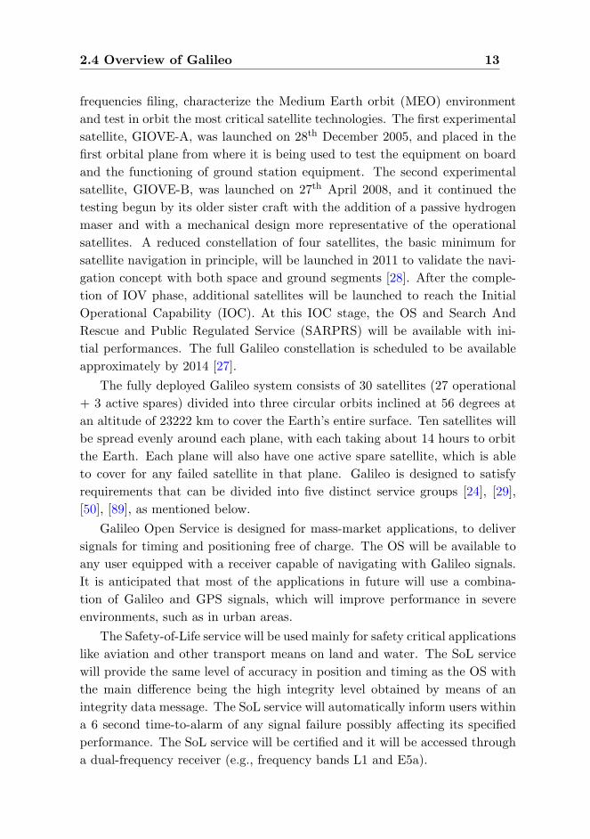
frequencies filing, characterize the Medium Earth orbit (MEO) environment
and test in orbit the most critical satellite technologies. The first experimental
satellite, GIOVE-A, was launched on 28th December 2005, and placed in the
first orbital plane from where it is being used to test the equipment on board
and the functioning of ground station equipment. The second experimental
satellite, GIOVE-B, was launched on 27th April 2008, and it continued the
testing begun by its older sister craft with the addition of a passive hydrogen
maser and with a mechanical design more representative of the operational
satellites. A reduced constellation of four satellites, the basic minimum for
satellite navigation in principle, will be launched in 2011 to validate the navi-
gation concept with both space and ground segments [28]. After the comple-
tion of IOV phase, additional satellites will be launched to reach the Initial
Operational Capability (IOC). At this IOC stage, the OS and Search And
Rescue and Public Regulated Service (SARPRS) will be available with ini-
tial performances. The full Galileo constellation is scheduled to be available
approximately by 2014 [27].
The fully deployed Galileo system consists of 30 satellites (27 operational
+ 3 active spares) divided into three circular orbits inclined at 56 degrees at
an altitude of 23222 km to cover the Earth’s entire surface. Ten satellites will
be spread evenly around each plane, with each taking about 14 hours to orbit
the Earth. Each plane will also have one active spare satellite, which is able
to cover for any failed satellite in that plane. Galileo is designed to satisfy
requirements that can be divided into five distinct service groups [24], [29],
[50], [89], as mentioned below.
Galileo Open Service is designed for mass-market applications, to deliver
signals for timing and positioning free of charge. The OS will be available to
any user equipped with a receiver capable of navigating with Galileo signals.
It is anticipated that most of the applications in future will use a combina-
tion of Galileo and GPS signals, which will improve performance in severe
environments, such as in urban areas.
The Safety-of-Life service will be used mainly for safety critical applications
like aviation and other transport means on land and water. The SoL service
will provide the same level of accuracy in position and timing as the OS with
the main difference being the high integrity level obtained by means of an
integrity data message. The SoL service will automatically inform users within
a 6 second time-to-alarm of any signal failure possibly affecting its specified
performance. The SoL service will be certified and it will be accessed through
a dual-frequency receiver (e.g., frequency bands L1 and E5a).

14 GLOBAL NAVIGATION SATELLITE SYSTEMS
The Commercial Service (CS) is aimed at market applications which re-
quire higher performance than offered by the OS. It will provide value-added
services on payment of a fee with the addition of two signals to the OS signal.
This pair of additional signals is protected at receiver level through commer-
cial encryption using access-protection keys, which will be managed by the
service providers and a future Galileo operating company. These value-added
services include, e.g., high data-rate broadcasting, precise timing services, ser-
vice guarantees, the provision of ionosphere delay models, and local differential
correction signals for extreme-precision position determination.
The fourth service that Galileo will offer is the Public Regulated Service
(PRS) that is expected to be used by groups such as the police, coastguard
and customs. Civilian institutions will control access to the encrypted public
regulated service, which is mandated to be operational due to the robustness
of its signal at all times and in all circumstances, especially during periods of
crisis, when some other services may be intentionally jammed.
The fifth service, Search And Rescue (SAR), will allow important im-
provements to the existing humanitarian search and rescue services. These
will include near real-time reception of distress messages from anywhere on
the Earth and transferring it to a rescue coordination center. A return signal
will then be sent back to the users advising that help is on the way.
2.5 Overview of GLONASS
GLONASS satellite navigation system, the Russian counterpart to GPS be-
came fully operational in 1995. The operational space segment of GLONASS
consists of 21 satellites with 3 on-orbit spares. Nominally, these satellites are
in three orbital planes separated by 120 degrees, and equally spaced within
each plane at a nominal inclination of 64.8 degrees. The orbits are roughly
circular and the satellites orbit the Earth at an altitude of 19100 km, which
yields an orbital period of approximately 11 hours and 15 minutes. Due to lack
of funding and relatively short life span of only 3 to 4.5 years, the GLONASS
constellation could not be maintained and the number of operational satellites
decreased to only 7 in 2001. Forced by a GLONASS modernization program,
the number of operational satellites has now been increased to 20 at the end
of 2010. With the modernization effort, the GLONASS performance is ex-
pected to be comparable to that of GPS and Galileo. In order to achieve this
goal, the GLONASS modernization plan includes modernization of satellites
transmitting new navigation signals, extension of the existing ground support
2.6 Other Satellite Navigation Systems 15
segment, augmentation of the system with differential services and the use
of optimized methods and algorithms for time synchronization or orbit deter-
mination. The core part of the space segment modernization will be a new
generation of GLONASS satellites, named as GlONASS-M and GLONASS-
K. The new modernization plan includes the addition of a new signal using
CDMA technique, similar to the one used in GPS. The legacy GLONASS is
built around Frequency Division Multiple Access (FDMA) technique, so this
would be a huge move in terms of compatibility and interoperability with other
existing GNSSs.
2.6 Other Satellite Navigation Systems
In recent years, there have been many activities all around the globe that
intend to provide either full navigation capabilities or local or regional aug-
mentations to the global positioning systems. This is the case for Beidou (i.e.,
the Chinese satellite-based regional navigation system), which has now been
expanded to a global navigation system in the form of Compass by the end of
this decade. There are also GAGAN (GPS Aided Geo Augmented Navigation)
from India and QZSS (Quasi-Zenith Satellite System) from Japan, which also
provide regional augmentations to India and Japan, respectively.
2.7 GNSS Applications
As of now, GPS is the only prevailing GNSS primarily used by both military
and civilian users. However, the future users will have several additional GNSS
systems at their disposal as new systems (for example, Galileo) come online.
Many of these GNSS signals, being free and globally available, will be used
in advanced applications that were initially pioneered by GPS. Some of the
major GNSS applications are briefly summarized below:
• Personal navigation: This consists of applications to aid people to
navigate. Perhaps the most known form of personal navigation are the
car navigators navigating the user to a specified location. GNSS is cur-
rently making its way into cell phones (for example, Nokia E97, N97, N8
[88]; iPhone 4 [1], etc.) and PDAs, expanding satellite navigation to a
large new group of users.
• Aviation applications: The aviation users require a very high level of

16 GLOBAL NAVIGATION SATELLITE SYSTEMS
performance in terms of accuracy and robustness for en route navigation
as well as for precision approach and landing.
• Marine applications: GNSS emerged as a blessing to marine users due
to the clear views of the sky and modest accuracy requirements of most
maritime applications. Today, GNSS receivers have become standard
equipment for all types of boats, and they perform a very precious service
to the global maritime community.
• Space applications: GNSS receivers, GPS in particular, have proven
to be a very valuable tool for Low Earth Orbit (LEO) satellites. Their
use is currently expanding into space vehicles operating at higher al-
titudes. GPS has the full potential to be implemented as an attitude
determination sensor.
• Geodesy and surveying: The users of these applications are perhaps
utilizing the best benefits that have resulted from the public availability
of GPS signals. Geodesy applications require precision positioning in-
formation at the centimeter or millimeter level and include applications
such as the monitoring of the movements of the Earth’s crystal plates or
ice shelves, often involving extensive post-processing [42]. Similarly, sur-
veying with GNSS receivers has also become widespread with relatively
relaxed accuracy requirements.
• Forestry, agriculture and natural resource exploration: These
diverse applications include forest management, geological monitoring,
mining, and oil exploration. These applications often combine GNSS
field measurements with geographic information system tools to produce
accurate regional maps for resource monitoring and management.
In addition to all the above listed applications, there are also many other
application areas which are becoming more and more attractive for GNSS
users. One such application area is object and person tracking. Many personal
tracking applications are developed for sports, both to enhance training [25],
[120], and spectator experience in sports like car racing, cricket, triathlon,
cycling, etc. Asset tracking is another example of this, where trains, trucks
and valuable containers can be tracked for better management and increased
security [99].

Chapter 3
Signal and Channel Model
In this chapter, the Binary Offset Carrier (BOC) modulation used in modern-
ized GPS and Galileo systems is explained. Next, an overview of a simplified
baseband signal and channel model for GNSS signals is presented in the con-
text of this thesis. It is worth to mention here that the work carried out in
this thesis mainly focuses on three different signal modulations, namely Binary
Phase Shift Keying (BPSK) modulation used in legacy GPS L1 C/A signal,
Multiplexed Binary Offset Carrier (MBOC) modulation used in Galileo E1
signal and modernized GPS L1C signal, and Sine BOC (SinBOC) modula-
tion that can be used as an alternative to demodulated MBOC signal at the
receiver side.
3.1 Binary Offset Carrier Modulation
The BOC modulation was first introduced by Betz for the modernized GPS
system [5], [8]. Since then, several variants have been developed including Sine
BOC and Cosine BOC (CosBOC) [6], [8], Alternative BOC (AltBOC) [50],
[51], Complex Double BOC (CDBOC) [76] and Multiplexed BOC (MBOC)
modulations [49], [106]. According to the July 2007 agreement between the
EU and the US [113], there will be a common GPS-Galileo signal, known as
MBOC, for civilian use in order to ensure the compatibility and interoperabil-
ity at the user level. The second Galileo satellite, GIOVE-B already started
transmitting the Galileo E1 signal with the MBOC modulation, that will be
interoperable with the L1C signal to be used in future Block III GPS satellites.
In this thesis, the MBOC modulation and its variants are considered as they
are specified to be used for civilan users in both GPS and Galileo systems. In
17
18 SIGNAL AND CHANNEL MODEL
addition, BPSK modulation used for GPS L1 C/A signal and SinBOC(1,1)
modulation used to form the MBOC signal, are also considered in this thesis
as benchmark modulations.
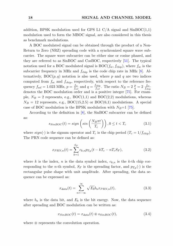
A BOC modulated signal can be obtained through the product of a Non-
Return to Zero (NRZ) spreading code with a synchronized square wave sub-
carrier. The square wave subcarrier can be either sine or cosine phased, and
they are referred to as SinBOC and CosBOC, respectively [51]. The typical
notation used for a BOC modulated signal is BOC(fsc, fchip), where fsc is the
subcarrier frequency in MHz and fchip is the code chip rate in MHz [8]. Al-
ternatively, BOC(p, q) notation is also used, where p and q are two indices
computed from fsc and fchip, respectively, with respect to the reference fre-
quency fref = 1.023 MHz, p = fscfref
and q =fchipfref
. The ratio NB = 2 pq = 2 fsc
fchipdenotes the BOC modulation order and is a positive integer [75]. For exam-
ple, NB = 2 represents, e.g., BOC(1,1) and BOC(2,2) modulations, whereas
NB = 12 represents, e.g., BOC(15,2.5) or BOC(6,1) modulations. A special
case of BOC modulation is the BPSK modulation with NB=1 [75].
According to the definition in [8], the SinBOC subcarrier can be defined
as:
sSinBOC(t) = sign
(sin
(NBπt
Tc
)), 0 ≤ t < Tc (3.1)
where sign(·) is the signum operator and Tc is the chip period (Tc = 1/fchip).
The PRN code sequence can be defined as:
xPRN,n(t) =
SF∑k=1
ck,npTB(t− kTc − nTcSF ), (3.2)
where k is the index, n is the data symbol index, ck,n is the k-th chip cor-
responding to the n-th symbol, SF is the spreading factor, and pTB(·) is the
rectangular pulse shape with unit amplitude. After spreading, the data se-
quence can be expressed as:
xdata(t) =∞∑
n=−∞
√EbbnxPRN,n(t), (3.3)
where bn is the data bit, and Eb is the bit energy. Now, the data sequence
after spreading and BOC modulation can be written as:
xSinBOC(t) = xdata(t)~ sSinBOC(t), (3.4)
where ~ represents the convolution operation.

3.1 Binary Offset Carrier Modulation 19
The Composite BOC (CBOC) modulation, a variant of MBOC used in
Galileo E1 signal, can be written as [75]:
sCBOC(t) = w1sSinBOC(1,1),held(t)± w2sSinBOC(6,1)(t)
= w1
NB1−1∑
i=0
NB2NB1
−1∑k=0
(−1)ic
(t− i
Tc
NB1
− kTc
NB2
)
± w2
NB2−1∑
i=0
(−1)ic
(t− i
Tc
NB2
)(3.5)
In the above, when the two right-hand terms are added, additive CBOC or
CBOC(‘+’) is formed, and when the two terms are subtracted, we have the
inverse CBOC or CBOC(‘-’) implementation. Alternatively, CBOC(‘+/-’) im-
plementation can be used, when odd chips are CBOC(‘+’) modulated and
even chips are CBOC(‘-’) modulated [49]. In Eqn. 3.5, NB1 = 2 is the BOC
modulation order for SinBOC(1,1) signal, NB2 = 12 is the BOC modulation
order for SinBOC(6,1) signal, the term sSinBOC(1,1),held represents that Sin-
BOC(1,1) signal is passed through a hold clock in order to match the higher
rate of SinBOC(6,1); and w1 and w2 are amplitude weighting factors such
that w1 = sqrt(10/11) = 0.9535 and w2 = sqrt(1/11) = 0.3015, and c(t) is the
pseudorandom code. In Eqn. 3.5, the first term comes from the SinBOC(1,1)
modulated code (held at rate 12/Tc in order to match the rate of the second
term), and the second term comes from a SinBOC(6,1) modulated code.
Now, in case of Time Multiplexed BOC (TMBOC) modulation, a variant
of MBOC that will be used in modernized GPS L1C signal, the whole signal is
divided into blocks of Q code symbols and P < Q of Q code symbols are Sin-
BOC(1,1) modulated, while Q−P code symbols are SinBOC(6,1) modulated.
Using similar derivations as in [75], we can obtain the formula for TMBOC
waveform. An equivalent unified model of CBOC and TMBOC modulations
was derived in [78] using the facts that P,Q << ∞ and that, since w1, w2 are
amplitude coefficients and P , Q − P define the power division between Sin-
BOC(1,1) and SinBOC(6,1), we may set the following relationship between
w1, w2 and P,Q: w1 =√
PQ and w2 =
√Q−PP . Therefore, in accordance with
[78], the unified model can be written as:
sMBOC(t) = w1cδ(t)~ s1(t)~ pTB(t)
+ w2cδ(t)~ s2(t)~ pTB(t) (3.6)

20 SIGNAL AND CHANNEL MODEL
where δ(·) is the Dirac pulse, ~ is the convolution operation, pTB(·) is a rect-
angular pulse of support Tc/NB2 with unit amplitude and cδ(t) is the code
signal without pulse shaping:
cδ(t) =√
Eb
∞∑n=−∞
bn
SF∑m=1
cm,nδ(t− nTcSF −mTc), (3.7)
and s1(t), s2(t) are SinBOC-modulated parts (with associated hold block when
needed), given by:
s1(t) =
NB1−1∑
i=0
NB2NB1
−1∑k=0
(−1)iδ(t− iTc
NB1
− kTc
NB2
), (3.8)
and, respectively:
s2(t) =
NB2−1∑
i=0
(−1)iδ(t− iTc
NB2
). (3.9)
3.2 Channel Model
Typical GNSS signals, such as those used in GPS or Galileo employ DS-CDMA
technique, where a Pseudo-Random Noise (PRN) code from a specific satellite
is spreading the navigation data over SF chips (or over a code epoch length)
[30], [60]. In what follows, a baseband model is adopted for clarity reason.
The estimation of code delay in today’s receivers is typically done in digital
domain using the baseband correlation samples. In the following, the time
notation t denotes the discrete time instant. The signal x(t) transmitted from
one satellite with a specific PRN code can be written as:
x(t) =√
EbpMOD(t)~ c(t), (3.10)
where Eb is the bit energy, pMOD(t) is the modulation waveform of type MOD
(i.e., BPSK for GPS L1 C/A code or CBOC(-) for Galileo E1C signals), and
c(t) is the navigation data after spreading as written below (spreading is done
with a PRN code of chip interval Tc and spreading factor SF ):
c(t) =
∞∑n=−∞
bn
SF∑k=1
ck,nδ(t− nTcSF − kTc). (3.11)
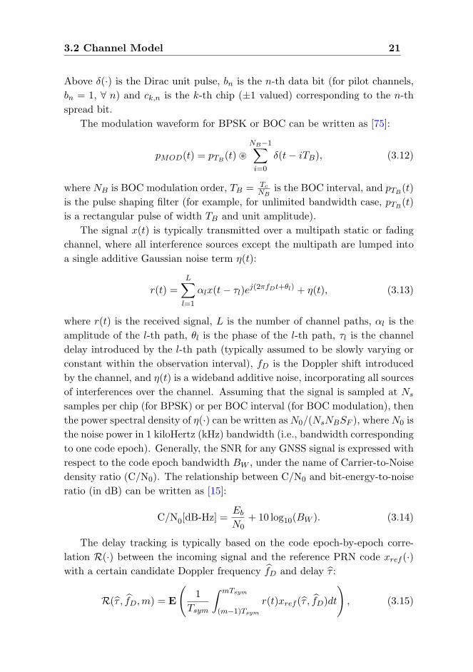
3.2 Channel Model 21
Above δ(·) is the Dirac unit pulse, bn is the n-th data bit (for pilot channels,
bn = 1, ∀ n) and ck,n is the k-th chip (±1 valued) corresponding to the n-th
spread bit.
The modulation waveform for BPSK or BOC can be written as [75]:
pMOD(t) = pTB(t)~
NB−1∑i=0
δ(t− iTB), (3.12)
where NB is BOC modulation order, TB = TcNB
is the BOC interval, and pTB(t)
is the pulse shaping filter (for example, for unlimited bandwidth case, pTB(t)
is a rectangular pulse of width TB and unit amplitude).
The signal x(t) is typically transmitted over a multipath static or fading
channel, where all interference sources except the multipath are lumped into
a single additive Gaussian noise term η(t):
r(t) =
L∑l=1
αlx(t− τl)ej(2πfDt+θl) + η(t), (3.13)
where r(t) is the received signal, L is the number of channel paths, αl is the
amplitude of the l-th path, θl is the phase of the l-th path, τl is the channel
delay introduced by the l-th path (typically assumed to be slowly varying or
constant within the observation interval), fD is the Doppler shift introduced
by the channel, and η(t) is a wideband additive noise, incorporating all sources
of interferences over the channel. Assuming that the signal is sampled at Ns
samples per chip (for BPSK) or per BOC interval (for BOC modulation), then
the power spectral density of η(·) can be written asN0/(NsNBSF ), whereN0 is
the noise power in 1 kiloHertz (kHz) bandwidth (i.e., bandwidth corresponding
to one code epoch). Generally, the SNR for any GNSS signal is expressed with
respect to the code epoch bandwidth BW , under the name of Carrier-to-Noise
density ratio (C/N0). The relationship between C/N0 and bit-energy-to-noise
ratio (in dB) can be written as [15]:
C/N0[dB-Hz] =Eb
N0+ 10 log10(BW ). (3.14)
The delay tracking is typically based on the code epoch-by-epoch corre-
lation R(·) between the incoming signal and the reference PRN code xref (·)with a certain candidate Doppler frequency fD and delay τ :
R(τ , fD,m) = E
(1
Tsym
∫ mTsym
(m−1)Tsym
r(t)xref (τ , fD)dt
), (3.15)
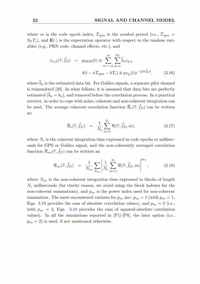
22 SIGNAL AND CHANNEL MODEL
where m is the code epoch index, Tsym is the symbol period (i.e., Tsym =
SFTc), and E(·) is the expectation operator with respect to the random vari-
ables (e.g., PRN code, channel effects, etc.), and
xref (τ , fD) = pMOD(t)~∞∑
n=−∞
SF∑k=1
bnck,n
δ(t− nTsym − kTc)~ pTB(t)e−j2πfDt, (3.16)
where bn is the estimated data bit. For Galileo signals, a separate pilot channel
is transmitted [30]. In what follows, it is assumed that data bits are perfectly
estimated (bn = bn), and removed before the correlation process. In a practical
receiver, in order to cope with noise, coherent and non-coherent integration can
be used. The average coherent correlation function Rc(τ , fD) can be written
as:
Rc(τ , fD) =1
Nc
Nc∑m=1
R(τ , fD,m), (3.17)
where Nc is the coherent integration time expressed in code epochs or millisec-
onds for GPS or Galileo signal, and the non-coherently averaged correlation
function Rnc(τ , fD) can be written as:
Rnc(τ , fD) =1
Nnc
∑Nnc
∣∣∣∣∣ 1Nc
Nc∑m=1
R(τ , fD,m)
∣∣∣∣∣pnc
, (3.18)
where Nnc is the non-coherent integration time expressed in blocks of length
Nc milliseconds (for clarity reason, we avoid using the block indexes for the
non-coherent summations), and pnc is the power index used for non-coherent
summation. The most encountered variants for pnc are: pnc = 1 (with pnc = 1,
Eqn. 3.18 provides the sum of absolute correlation values), and pnc = 2 (i.e.,
with pnc = 2, Eqn. 3.18 provides the sum of squared-absolute correlation
values). In all the simulations reported in [P1]-[P8], the later option (i.e.,
pnc = 2) is used, if not mentioned otherwise.
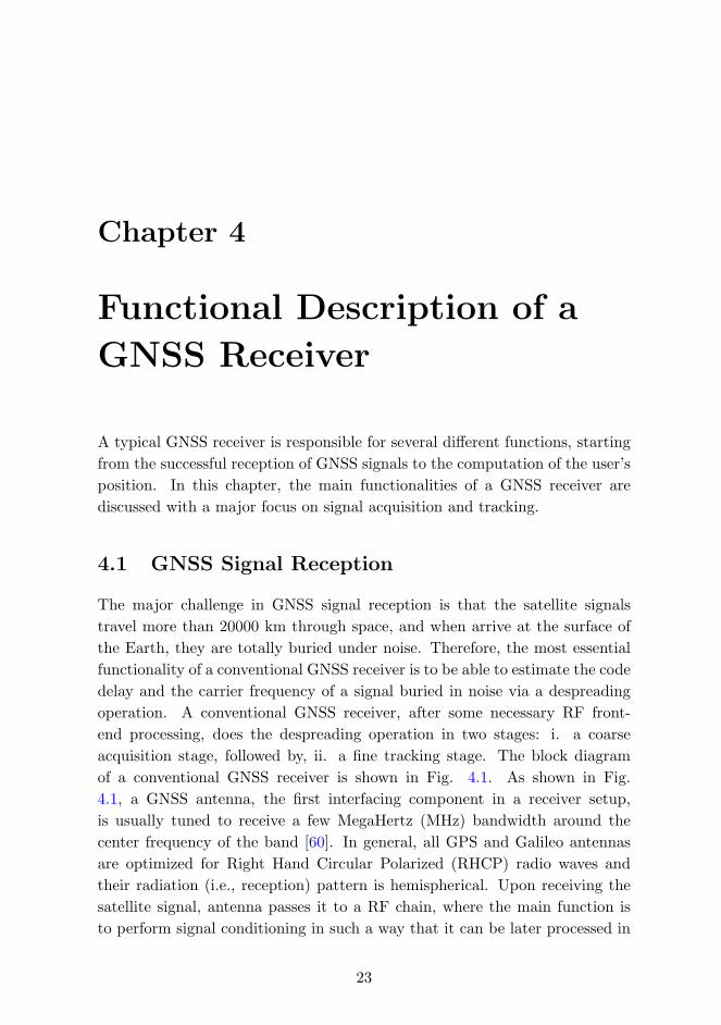
Chapter 4
Functional Description of a
GNSS Receiver
A typical GNSS receiver is responsible for several different functions, starting
from the successful reception of GNSS signals to the computation of the user’s
position. In this chapter, the main functionalities of a GNSS receiver are
discussed with a major focus on signal acquisition and tracking.
4.1 GNSS Signal Reception
The major challenge in GNSS signal reception is that the satellite signals
travel more than 20000 km through space, and when arrive at the surface of
the Earth, they are totally buried under noise. Therefore, the most essential
functionality of a conventional GNSS receiver is to be able to estimate the code
delay and the carrier frequency of a signal buried in noise via a despreading
operation. A conventional GNSS receiver, after some necessary RF front-
end processing, does the despreading operation in two stages: i. a coarse
acquisition stage, followed by, ii. a fine tracking stage. The block diagram
of a conventional GNSS receiver is shown in Fig. 4.1. As shown in Fig.
4.1, a GNSS antenna, the first interfacing component in a receiver setup,
is usually tuned to receive a few MegaHertz (MHz) bandwidth around the
center frequency of the band [60]. In general, all GPS and Galileo antennas
are optimized for Right Hand Circular Polarized (RHCP) radio waves and
their radiation (i.e., reception) pattern is hemispherical. Upon receiving the
satellite signal, antenna passes it to a RF chain, where the main function is
to perform signal conditioning in such a way that it can be later processed in
23

24 FUNCTIONAL DESCRIPTION OF A GNSS RECEIVER
the receiver. Signal conditioning in the RF front-end includes several signal
processing operations like amplification, filtering, down-conversion, mixing,
Automatic Gain Control (AGC), Analog-to-Digital Conversion (ADC) and so
on. The functional description of each of this signal processing operation is
well-documented in literature, for example, in [15], [60], and [92]; and hence,
it is not elaborated herein for the sake of clarity and compactness.
Figure 4.1: A conventional GNSS receiver block diagram.
4.2 Signal Acquisition
The purpose of signal acquisition is to determine the visible satellites and to
achieve the coarse estimates of the carrier frequency and of the code phase of
the satellite signals. Like any other CDMA-based receivers, a GNSS receiver
also achieves this acquisition operation in two stages, namely, the search stage
and the detection stage, which are briefly summarized below.
4.2.1 Signal Search Stage
GNSS signal acquisition is a three-dimensional search process, which deter-
mines the identity of the received signal (i.e., Satellite Vehicle (SV) number),
code delay and Doppler shift. The search process requires that, for a certain
SV, both the replica code and the carrier are aligned with the received signal.
The correct alignment is identified by measurement of the output power of the
correlators. In other words, when both the code and carrier Doppler match
the incident signal, the signal is despread and a carrier signal is recovered. The
result of the code and Doppler search is an estimate of the code offset typically

4.2 Signal Acquisition 25
within 1/2 chip and the Doppler to within half the Doppler search bin size.
In case of a Galileo E1 receiver, acquisition can be performed using a carrier
signal and a E1B or a E1C or a coherently or a non-coherently combined E1B
and E1C code replica [11], [110].
Search Space
The search space must cover the full range of uncertainty in the code delay
and Doppler frequency domain. The code search space is typically equal to
the length of the spreading code, which is 1023 chips for GPS L1 C/A signal,
and 4092 chips for Galileo E1 OS signal. The resolution of the code search is
typically set to a fraction of a chip (i.e., ≤ 1/2 chip for GPS L1 C/A signal),
and it can often be specified by the sampling frequency of the received signal.
The Doppler search space is governed by the receiver and GNSS satellite dy-
namics and the stability of the receiver oscillator. For a terrestrial user system,
this is typically in the range of 5 to 10 kHz [64]. The frequency resolution is
determined by the coherent integration time (or dwell time). According to
[60], the rule of thumb is: ∆f = 23Tcoh
, where ∆f is the frequency bin width
in hertz and Tcoh is the predetection integration time in seconds.
Search Window
Each tentative code delay is called a code bin (or a time bin), and respectively,
each tentative frequency shift is denoted as a Doppler bin (or a frequency
bin). A single code bin along with a frequency bin compose a search bin or
a test cell [60]. The whole code-frequency search space can be divided into
several search windows depending on the type of search techniques chosen for
implementation.
Search Techniques
The proposed PRN codes for Galileo have higher lengths (e.g., 4092 chips for
E1 OS signal and 10230 chips for E5 signals [30]) than those used by legacy
GPS C/A signal. The use of longer codes leads to an increased search space,
which eventually makes the search process more time consuming. Several
search techniques have been proposed in literature (for example, in [60], [83],
and [92]) in order to obtain a faster and a more efficient signal acquisition.
These search techniques can be classified in three major categories as serial
search, parallel search and combined serial/parallel search (or, hybrid search).
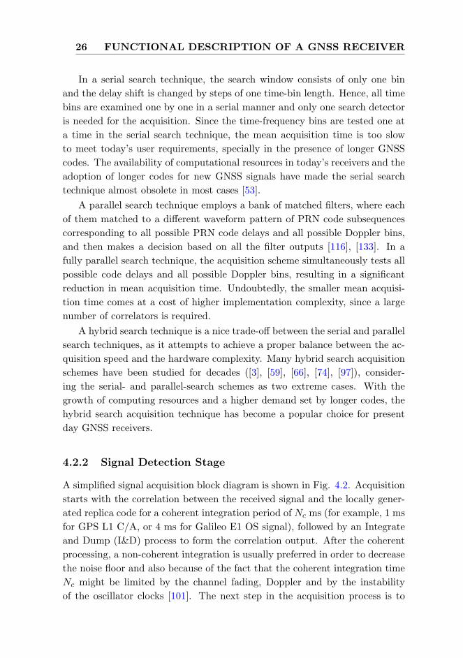
26 FUNCTIONAL DESCRIPTION OF A GNSS RECEIVER
In a serial search technique, the search window consists of only one bin
and the delay shift is changed by steps of one time-bin length. Hence, all time
bins are examined one by one in a serial manner and only one search detector
is needed for the acquisition. Since the time-frequency bins are tested one at
a time in the serial search technique, the mean acquisition time is too slow
to meet today’s user requirements, specially in the presence of longer GNSS
codes. The availability of computational resources in today’s receivers and the
adoption of longer codes for new GNSS signals have made the serial search
technique almost obsolete in most cases [53].
A parallel search technique employs a bank of matched filters, where each
of them matched to a different waveform pattern of PRN code subsequences
corresponding to all possible PRN code delays and all possible Doppler bins,
and then makes a decision based on all the filter outputs [116], [133]. In a
fully parallel search technique, the acquisition scheme simultaneously tests all
possible code delays and all possible Doppler bins, resulting in a significant
reduction in mean acquisition time. Undoubtedly, the smaller mean acquisi-
tion time comes at a cost of higher implementation complexity, since a large
number of correlators is required.
A hybrid search technique is a nice trade-off between the serial and parallel
search techniques, as it attempts to achieve a proper balance between the ac-
quisition speed and the hardware complexity. Many hybrid search acquisition
schemes have been studied for decades ([3], [59], [66], [74], [97]), consider-
ing the serial- and parallel-search schemes as two extreme cases. With the
growth of computing resources and a higher demand set by longer codes, the
hybrid search acquisition technique has become a popular choice for present
day GNSS receivers.
4.2.2 Signal Detection Stage
A simplified signal acquisition block diagram is shown in Fig. 4.2. Acquisition
starts with the correlation between the received signal and the locally gener-
ated replica code for a coherent integration period of Nc ms (for example, 1 ms
for GPS L1 C/A, or 4 ms for Galileo E1 OS signal), followed by an Integrate
and Dump (I&D) process to form the correlation output. After the coherent
processing, a non-coherent integration is usually preferred in order to decrease
the noise floor and also because of the fact that the coherent integration time
Nc might be limited by the channel fading, Doppler and by the instability
of the oscillator clocks [101]. The next step in the acquisition process is to

4.2 Signal Acquisition 27
determine whether the satellite signal is present or absent (i.e., if there is a
synchronization between the code and the received signal or not). This is the
main objective of the detection stage.
Figure 4.2: A simplified signal acquisition block diagram.
At the detection stage, a test statistic is usually computed per each search
window based on the current correlation output, and then this test statistic is
compared to a certain predetermined threshold γ in order to decide whether
the signal is present or absent. The test statistic can be formed, for example,
as the value of the global maximum of the correlation output in one search
window [22], [111] or as the ratio between the global maximum and the next
significant local maximum [58], [90], [91]. If the value of the test statistic is
higher than the threshold, the signal is decided to be present and an estimate
for the code phase and frequency is achieved. The time to form the test
statistic is usually denoted as the dwell time τd. Every time when the test
statistic is higher than the threshold, the signal is decided to be present.
The probability of a signal being detected correctly is denoted as a detection
probability Pd. A false alarm triggers when a delay and/or frequency estimate
is wrong but the test statistic is still higher than the threshold, i.e., the signal
is declared present in an incorrect window. The probability of a false alarm
is denoted as the false alarm probability Pfa. It may also happen that the
signal is present, but not detected: a miss detection occurs. This may happen
if the threshold is set too high or the environment is so noisy that the signal
is lost into the background noise. Therefore, the choice of a suitable detection
threshold γ has a significant role in the acquisition process. If the threshold
is set too low, the probability of detection (i.e., Pd) naturally increases, but
at the same time, the probability of false alarm (i.e., Pfa) increases as well.
28 FUNCTIONAL DESCRIPTION OF A GNSS RECEIVER
Respectively, if the threshold is set too high, the Pfa decreases, but also the
Pd is low. The selection of a suitable detection threshold can be found, for
example, in [61].
4.3 Signal Tracking
4.3.1 Background on Tracking Loops
The signal tracking stage refines the estimates of the signal parameters (i.e.,
code delay and Doppler frequency) obtained at the acquisition stage. In fact,
these parameters are not accurate enough to be used for positioning and nav-
igation. Apart from that, the carrier phase information is also ignored at
the acquisition stage and more interestingly, all these parameters change over
time. The tracking stage gives a fine estimate of the code delay, the Doppler
frequency and the carrier phase, and it continuously follows their variations.
The signal tracking stage consists of two inter-connected tracking loops.
They are used for tracking the quantities to be estimated: the code delay τ , the
Doppler frequency fD, and the carrier phase ϕ in the form of Delay Locked
Loop (DLL), Frequency Locked Loop (FLL) or Phase Locked Loop (PLL),
respectively. In certain applications, FLL and PLL can be used in sequence
or in a FLL-assisted-PLL configuration, where the receiver uses the FLL first
in order to reduce the frequency uncertainty before switching to PLL [114].
A similar FLL-assisted-PLL configuration was also implemented in the TUT
Galileo E1 Simulink receiver, as mentioned in [110].
Both the DLL and FLL-assisted-PLL loops are closely inter-related and
they work in an inter-connected way. More specifically, the DLL is used to
reproduce a local version of the spreading code that is removed from the
incoming signal before entering the PLL (code wipe-off). In this way, a pure
carrier is found at the input of the PLL. Similarly, the PLL is used to generate
a local version of the signal carrier that is down-converted to baseband. In
this way, a noisy baseband binary sequence enters the DLL (carrier wipe-off).
4.3.2 Multi-Correlator based Delay Tracking Structure
In a multi-correlator based delay tracking structure, a bank of correlators is
generated, unlike the conventional DLL-based tracking structure, where only
few correlators (i.e., in the range of three to seven complex correlators depend-
ing on the type of techniques) are used. This large number of correlators are
required by the advanced multipath mitigation techniques, as we proposed in

4.3 Signal Tracking 29
[P2] and [P8], in order to estimate the channel properties and to take a deci-
sion on the correct LOS code delay. As shown in Fig. 4.3, after the necessary
Figure 4.3: Block diagram for multi-correlator based DLL implementation.
front-end processing, and after the carrier has been wiped-off, the received
post-processed signal is passed through a bank of correlators. The NCO (Nu-
merically Controlled Oscillator) and PRN generator block produces a bank of
early and late versions of replica codes based on the delay of the LOS signal
τ , the correlator spacing ∆, and the number of correlators M . In case of an
EML tracking loop, the corresponding early-late spacing is equal to 2∆. The
received signal is correlated with each replica in the correlator bank, and the
output of the correlator bank is a vector of samples in the correlation envelope.
Therefore, we obtain the correlation values for the range of ±M∆ chips from
the prompt correlator, where M is the number of correlators and ∆ is the
correlator spacing between successive correlators. The various code tracking
techniques (named as Discriminator in Fig. 4.3) utilize the correlation val-
ues as input, and generate the estimated LOS delay as output, which is then
smoothed by a loop filter. A loop filter is generally used to improve the code
delay estimate, reducing the noise present at the output of the discriminator,
and to follow the signal dynamics. The order of a loop filter determines the
ability of the filter to respond to different types of dynamics, whereas the filter
bandwidth ensures that a low bandwidth leads to a good filtering with a high

30 FUNCTIONAL DESCRIPTION OF A GNSS RECEIVER
amount of noise filtered, but also requires that the dynamics of the signals are
not too high. The loop bandwidth is usually determined by the coefficients of
the filter, and can thus be considered as a design parameter for the filter. In
accordance with [60], the code loop filter implemented in [P7], is a 1st order
filter, which can be modeled as:
τ(k + 1) = τ(k) + ω0d(k), (4.1)
where ω0 is calculated based on the loop filter bandwidth, Bn. As shown in
[P7], the multi-correlator based tracking structure being used by the advanced
multipath mitigation techniques, offers a superior tracking performance to the
traditional nEML DLL at the cost of higher number of correlators. Therefore,
this structure is only suitable for professional high-end receivers.
4.3.3 C/N0 Estimation
C/N0 is an important parameter to measure the quality of a received GNSS
signal, that can also be used to enhance the performance of delay tracking
loops. The ratio between the received power of the signal carrier and the
noise power in a 1 Hz bandwidth is represented as C/N0 [67]. The total
power received by the antenna, as stated by the Friis transmission formula,
depends on the satellite transmitted power, the satellite antenna gain, the
receiver antenna gain, the free-space losses and the attenuations of the channel.
Standard GNSS receivers can handle signals with C/N0 in the range of 35–53
dB-Hz, whereas, high-sensitivity receivers can process even weaker signals.
The most known C/N0 estimation method is based on the ratio of the signal’s
wideband power to its narrowband power as mentioned in [92]. In this method,
the power of the signal is computed over a wide bandwidth with a relatively
short coherent integration time and over a narrow bandwidth with a longer
coherent integration time. In [P6], the author computed the wideband power
after 4 ms of coherent integration (after each code epoch length), and the
narrowband power after 16 ms of coherent integration in order to estimate the
C/N0 for each particular channel.
4.4 Navigation Solution
The navigation solution evaluates the user’s position and velocity from the
pseudoranges and the navigation data. An estimate of the user position and
velocity can be attempted in a GNSS receiver, only if the following conditions
are fulfilled:
4.4 Navigation Solution 31
1. A minimum of four satellites are being tracked.
2. The transmission time for each satellite at the measurement data sample
is known.
3. Ephemerides for the tracked satellites are available.
After fulfilling the above conditions, the ephemerides are processed in order to
obtain satellite locations and a navigation solution can be calculated based on
the satellite-to-user distances. The pseudoranges, determined by converting
the code delays into distances, provide the position of the user, whereas the
velocity is obtained by converting the information on the Doppler frequency.
The details on how to implement the navigation algorithms are out of scope
of this thesis, and the theory behind it is very well presented, for example, in
[12], [42], [60], [83], and [92].
32 FUNCTIONAL DESCRIPTION OF A GNSS RECEIVER

Chapter 5
Multipath and Other GNSS
Error Sources
Errors in satellite navigation signals can be classified into three main cat-
egories: satellite-based errors, signal propagation errors, and receiver-based
errors. Satellite-based errors include satellite clock error and ephemeris er-
ror. Signal propagation errors include errors associated with the atmospheric
propagation delay due to ionosphere, troposphere, multipath propagation de-
lay and interference. Receiver-based errors include receiver noise and other
smaller errors, such as, e.g., inter-channel biases and antenna error. A knowl-
edge on the possible error sources is essential in obtaining a user position
solution with the desired performance level. In the following, the various er-
ror sources of satellite navigation signals are discussed with a major focus on
multipath error, as being the most challenging error due to its uncorrelated
behavior.
5.1 Satellite-based Errors
Satellite-based errors consist of the errors in the orbital plane and of the satel-
lite clock parameters broadcast in the navigation message for which the GNSS
control segment is responsible. The prediction error of the satellite ephemeris
and clock parameters grows with the age of the data, i.e., the time since the
last parameters have been uploaded. Therefore, the more frequent the con-
trol segment uploads data to the satellites and the more accurate the models
used to estimate and predict the ephemeris and clock parameters, the less
significant are the satellite-based errors.
33
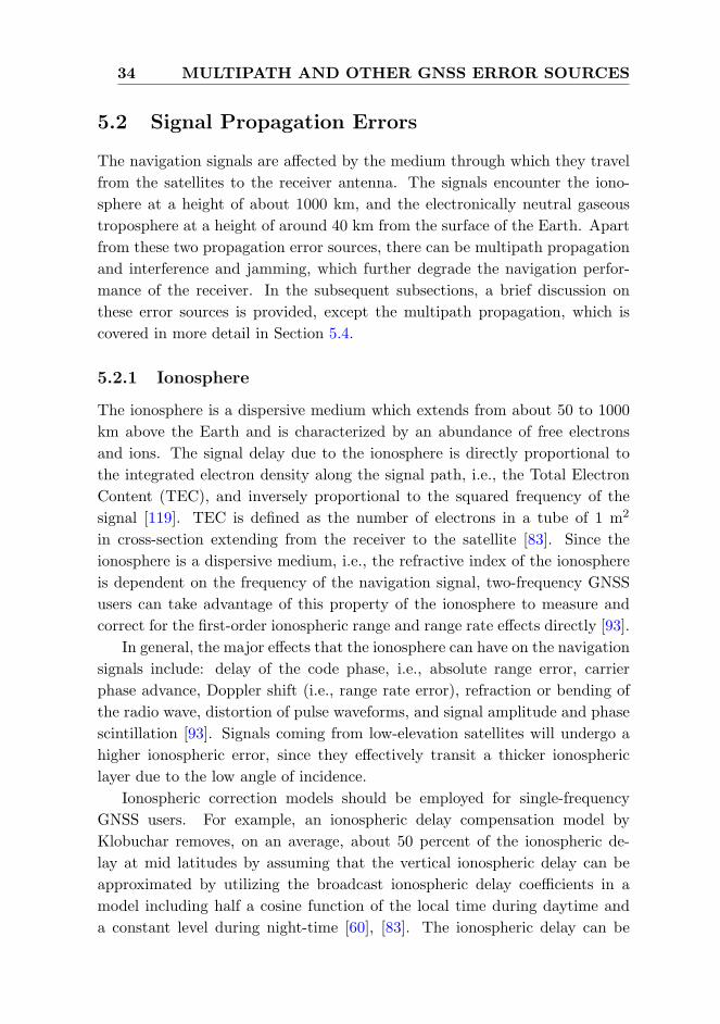
34 MULTIPATH AND OTHER GNSS ERROR SOURCES
5.2 Signal Propagation Errors
The navigation signals are affected by the medium through which they travel
from the satellites to the receiver antenna. The signals encounter the iono-
sphere at a height of about 1000 km, and the electronically neutral gaseous
troposphere at a height of around 40 km from the surface of the Earth. Apart
from these two propagation error sources, there can be multipath propagation
and interference and jamming, which further degrade the navigation perfor-
mance of the receiver. In the subsequent subsections, a brief discussion on
these error sources is provided, except the multipath propagation, which is
covered in more detail in Section 5.4.
5.2.1 Ionosphere
The ionosphere is a dispersive medium which extends from about 50 to 1000
km above the Earth and is characterized by an abundance of free electrons
and ions. The signal delay due to the ionosphere is directly proportional to
the integrated electron density along the signal path, i.e., the Total Electron
Content (TEC), and inversely proportional to the squared frequency of the
signal [119]. TEC is defined as the number of electrons in a tube of 1 m2
in cross-section extending from the receiver to the satellite [83]. Since the
ionosphere is a dispersive medium, i.e., the refractive index of the ionosphere
is dependent on the frequency of the navigation signal, two-frequency GNSS
users can take advantage of this property of the ionosphere to measure and
correct for the first-order ionospheric range and range rate effects directly [93].
In general, the major effects that the ionosphere can have on the navigation
signals include: delay of the code phase, i.e., absolute range error, carrier
phase advance, Doppler shift (i.e., range rate error), refraction or bending of
the radio wave, distortion of pulse waveforms, and signal amplitude and phase
scintillation [93]. Signals coming from low-elevation satellites will undergo a
higher ionospheric error, since they effectively transit a thicker ionospheric
layer due to the low angle of incidence.
Ionospheric correction models should be employed for single-frequency
GNSS users. For example, an ionospheric delay compensation model by
Klobuchar removes, on an average, about 50 percent of the ionospheric de-
lay at mid latitudes by assuming that the vertical ionospheric delay can be
approximated by utilizing the broadcast ionospheric delay coefficients in a
model including half a cosine function of the local time during daytime and
a constant level during night-time [60], [83]. The ionospheric delay can be

5.2 Signal Propagation Errors 35
determined from the broadcast parameters and the user’s latitude, longitude,
satellite elevation, azimuth angles, and local time.
5.2.2 Troposphere
The lower part of the Earth’s atmosphere, the troposphere, consists of dry
gases (i.e., the dry component) and water vapor (i.e., the wet component)
causing the GNSS signals to be refracted. Water vapor generally exists only
below altitudes of 12 km above sea level and most of the water vapor is below
4 km. The dry component of the troposphere (mainly N2 and O2 gases)
extends to a height of about 40 km. These dry gases, however, can be found
in gradually thinning layers at altitudes of hundreds of meters [83]. About
90 percent of the tropospheric delay is due to the dry component and it is
easily predictable based on the user latitude, altitude, and season. The wet
atmosphere consisting of water vapor is much harder to estimate since it varies
with local weather and can change rapidly. Models of the troposphere attempt
to estimate the dry and wet refractivities along the signal path in order to
predict the total tropospheric delay [83]. As distinct from the ionosphere, the
troposphere is non-dispersive, and hence, it induces the same delay on both
signal code and carrier.
5.2.3 Interference and Jamming
The satellite navigation frequency bands are well-protected by international
and Federal Communication Commission (FCC) frequency assignments. How-
ever, as GNSS signals are rather weak, they are vulnerable to unintentional
interference, and possibly even intentional interference [60], [92]. Any radio-
navigation system can be disrupted by interference of sufficiently high power.
Terrestrial interference caused by out-of-band emissions of other signal sources,
such as broadcast television, mobile and fixed Very High Frequency (VHF) and
Ultra High Frequency (UHF) transmitters, and ultra-wideband radar and com-
munications, may produce harmonics in the desired GNSS frequency bands.
This kind of interference can result either in degraded navigation performance
or even in a complete loss of receiver tracking.
The intentional emission of RF energy of sufficient power and characteris-
tics to prevent receivers in a target area from tracking GNSS signals is called
jamming [38]. Jamming can be accomplished by continuous waves, wideband,
narrowband, or GNSS-type signals typically exceeding the GNSS signal power
by around 40 dB to jam an already locked GNSS receiver. Techniques to

36 MULTIPATH AND OTHER GNSS ERROR SOURCES
improve jam-resistant GNSS receivers may be classified into precorrelation
methods that are waveform-specific and include adaptive spatial, temporal,
and spectral processing [38]. In addition, Receiver Autonomous Integrity Mon-
itoring (RAIM) and FDE (Fault Detection and Exclusion) methods can also
be used to mitigate the effects of unintentional and intentional interference
by detecting the inconsistency [65]. A more comprehensive illustration on
interference and jamming can be found in [13], [60], [85] and [92].
5.3 Receiver-based Errors
A receiver cannot perfectly follow changes in the signal waveform due to
receiver-based errors which include antenna error, inter-channel biases, ther-
mal noise, interference, signal quantization noise and tracking error. Inherent
receiver noise has random effects on the precision of the code and carrier mea-
surements. The measurement error due to receiver noise varies with the signal
strength (i.e., SNR), which, in turn, varies with the satellite navigation an-
gle [83]. Any source of interference that spectrally overlaps with the GNSS
signals will have some impact on the tracking performance since it will enter
the receiver front-end and will not be filtered out. In the delay locked loop
of a GNSS receiver, the dominant error sources are the thermal noise jitter
and the effects of dynamic stress, whereas the secondary error sources include
code hardware and software resolution, and oscillator stability [60].
5.4 The Major Challenge: Multipath
Multipath errors are mostly due to reflected GNSS signals from surfaces (such
as buildings, metal surfaces etc.) near the receiver, resulting in one or more
secondary propagation paths. These secondary path signals, which are super-
imposed on the desired direct path signal, always have a longer propagation
time and can significantly distort the amplitude and phase of the direct path
signal. This eventually leads to a deformation in the correlation function as
shown in Fig. 5.1, where a direct LOS signal is added constructively with an
in-phase (i.e., 0 phase difference), delayed (0.5 chips delayed) and attenuated
(-3 dB attenuated) version of it to form a compound signal. The deformed
correlation shape introduces an error bias in the pseudorange measurement
that resulted in a degraded positioning performance.
In severe multipath environments like those in dense urban areas, it may
be possible that the LOS signal is obstructed completely and only the reflected

5.4 The Major Challenge: Multipath 37
−2 −1.5 −1 −0.5 0 0.5 1 1.5 20
0.2
0.4
0.6
0.8
1
1.2
1.4
Code Delay [chips]
Co
rre
latio
n F
un
ctio
n
Impact of multipath on correlation shape
LOS SignalNLOS SignalCombined Signal
Figure 5.1: Received correlation function in two path static channel model,
path delays: [0 0.5] chips, path amplitudes: [0 -3] dB, in-phase combination.
signals are present. These multipath effects on the code phase measurements
are most crucial, and the multipath error can reach up to a few tens of meters,
or a couple of hundred at most [42]. Moreover, unlike other error sources,
multipath cannot be reduced through differential processing, since it decor-
relates spatially very rapidly. All these issues are the main driving factors
for the research conducted in the context of this thesis striving for an opti-
mum correlation-based multipath mitigation technique in terms of mitigation
performance as well as implementation complexity.
5.4.1 Influence of Signal and Receiver Parameters on Multi-
path Error
The way multipath affects the tracking and navigation performance of a re-
ceiver depends on a number of signal and receiver parameters. Among them,
the most influential parameters are:
• Type of signal modulation,
• Front-end filter bandwidth (i.e., precorrelation bandwidth),
• Correlator spacing used in the code tracking,
• Type of discriminator used to run the DLL (i.e., nEML, HRC, etc.),
• Code chipping rate,

38 MULTIPATH AND OTHER GNSS ERROR SOURCES
• Number of multipath signals,
• Amplitudes, delays and phases of multipath signals with respect to the
LOS signal, etc.
The type of signal modulation basically determines the shape of the corre-
lation function. For example, BPSK is used to modulate GPS L1 C/A signal,
which has a single significant tracking peak within ±1 chip delay from the cor-
rect code delay, whereas CBOC modulations (i.e. CBOC(+) for data channel
and CBOC(-) for pilot channel) are used to modulate Galileo E1 signal, each
of which has more than one significant tracking peak within ±1 chip delay
from the correct code delay. Non-coherent (i.e., absolute value of the cor-
relation function) correlation functions for the above modulations are shown
in Fig. 5.2, where the extra peaks can be clearly observed in case of CBOC
−1 −0.5 0 0.5 10
0.2
0.4
0.6
0.8
1
Code Delay [chips]
Non
−co
here
nt C
orre
latio
n F
unct
ion
Correlation shapes for different signal modulations
BPSKCBOC(+)CBOC(−)
Figure 5.2: Non-coherent correlation functions for different signal modulations.
modulations. This is the situation in the most ideal single path scenario. The
situation would get far worse in the presence of multipath signals, for example,
in a typical fading channel model with a two to four path assumption. Fig.
5.3 shows the distorted correlation shapes of different signal modulations in a
two path static channel with path delays [0 0.1] chips and with path powers
[0 -6] dB. As seen in Fig 5.3, the presence of an additional peak (in case of
CBOC(+) and CBOC(-)) due to multipath imposes a challenge for the signal
acquisition and tracking techniques to lock to the correct peak. If the receiver
fails to lock to the correct peak, a multipath error in the order of few tens of
meters is of no surprise.
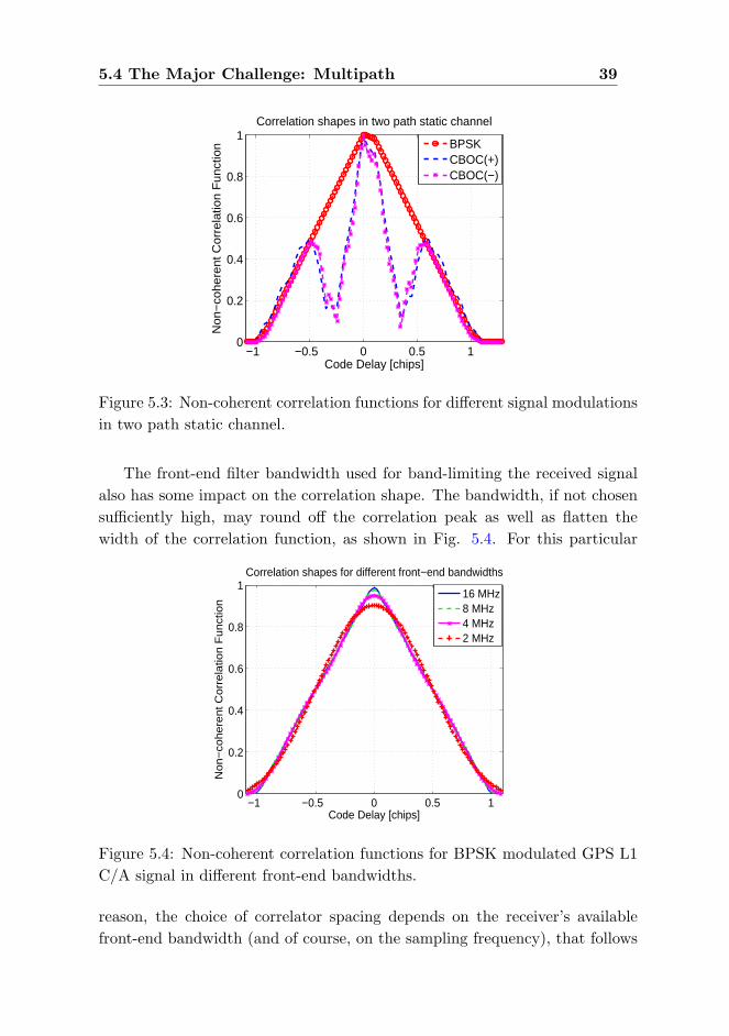
5.4 The Major Challenge: Multipath 39
−1 −0.5 0 0.5 10
0.2
0.4
0.6
0.8
1
Code Delay [chips]
Non
−co
here
nt C
orre
latio
n F
unct
ion
Correlation shapes in two path static channel
BPSKCBOC(+)CBOC(−)
Figure 5.3: Non-coherent correlation functions for different signal modulations
in two path static channel.
The front-end filter bandwidth used for band-limiting the received signal
also has some impact on the correlation shape. The bandwidth, if not chosen
sufficiently high, may round off the correlation peak as well as flatten the
width of the correlation function, as shown in Fig. 5.4. For this particular
−1 −0.5 0 0.5 10
0.2
0.4
0.6
0.8
1
Code Delay [chips]
No
n−
coh
ere
nt
Co
rre
latio
n F
un
ctio
n
Correlation shapes for different front−end bandwidths
16 MHz8 MHz4 MHz2 MHz
Figure 5.4: Non-coherent correlation functions for BPSK modulated GPS L1
C/A signal in different front-end bandwidths.
reason, the choice of correlator spacing depends on the receiver’s available
front-end bandwidth (and of course, on the sampling frequency), that follows

40 MULTIPATH AND OTHER GNSS ERROR SOURCES
the relation: the more the bandwidth, the smaller the correlator spacing. As
mentioned in [7], the early-late spacing ∆EL (i.e., twice the correlator spacing)
is related to the front-end bandwidth (double-sided) BW and the code chip
rate fchip according to the following equation:
∆EL ≥fchipBW
(5.1)
The type of the discriminator and the correlator spacing used to form the
discriminator function (i.e., nEML, HRC, SC, etc.) determines the behav-
ior of the code discriminator that strongly influences the resulting multipath
performance. Generally speaking, a narrower correlator spacing leads to a re-
duced multipath error and a tracking jitter error, as long as sufficient front-end
bandwidth is ensured [21].
The code chipping rate determines the chip length (Tc), which ultimately
decides the resulting ranging error caused by the multipath. This means that
a signal with a larger chip length results in a smaller multipath error contribu-
tion. That is why, the modernized GPS L5 signal can offer ten times smaller
multipath error contribution than the legacy GPS L1 C/A signal, as it has
ten times higher chipping rate than that of L1.
The remaining multipath related parameters (i.e., amplitudes, delays, phases
and number of multipath signals) depend on the multipath environment, and
have direct influence on the tracking performance of the receiver. These pa-
rameters are used to define various simulation models (for example, multipath
fading channel model) in order to analyze the performance of different multi-
path mitigation techniques developed in the context of this thesis along with
some of the most promising state-of-the-art techniques.
The echo-only signal reception is one example of a severe case of multipath
signal degradation, which occurs when there is no direct LOS signal between
the satellite and the receiver. Due to the absence of the LOS signal, it can
cause multipath error in the order of few tens of meters. Most of the multipath
mitigation techniques measure the pseudorange with respect to the first ar-
riving path, and unfortunately, there is no such straightforward way to detect
the reception of the echo-only signal.
Chapter 6
Multipath Mitigation
Techniques
Multipath remains a dominant source of ranging errors in GNSS, such as the
GPS or the developing European satellite navigation system, Galileo. Sev-
eral approaches have been implemented for the last few decades to reduce
the effect of multipath in a GNSS receiver. Among them, the use of special
multipath limiting antennas (i.e., choke ring or multi-beam antennas), the
post-processing techniques to reduce carrier multipath, the carrier smoothing
to reduce code multipath, and the code tracking algorithms based on the re-
ceiver internal correlation technique are the most prominent approaches [21].
In this thesis, the research focus is on the correlation-based multipath miti-
gation techniques, since they are the most widely used in commercial GNSS
receivers. This chapter provides a detail overview of the multipath mitigation
techniques, generalized here in four major categories: i. the state-of-the-art
techniques, which are already available in commercial receivers; ii. the pro-
posed advanced techniques, which have relatively complex implementation;
iii. the proposed simple slope-based technique, which does not require many
correlators; and iv. the proposed combined techniques, which are a combina-
tion of two different techniques. Among the proposed advanced techniques,
the non-coherent MEDLL is proposed in [P2], the basic Peak Tracking and
its improved variants are proposed in [P1] and [P2], respectively, and the ba-
sic Reduced Search Space Maximum Likelihood (RSSML) delay estimator is
proposed first in [P4], and it is later enhanced in [P7]. The proposed simple
slope-based multipath mitigation technique, named as Slope-Based Multipath
Estimator (SBME), is proposed in [P5], which requires a-priori information
41

42 MULTIPATH MITIGATION TECHNIQUES
about the slope of the correlation function and an additional correlator to
estimate the multipath error. Among the proposed combined techniques, a
C/N0-based two-stage delay estimator is proposed in [P6], and a Teager Kaiser
(TK) operator combined with nEML DLL is proposed in [P7].
6.1 State-of-the-art Techniques
The state-of-the-art multipath mitigation techniques are already commer-
cially available in GNSS receivers. The GNSS community has started the
correlation-based multipath mitigation studies in early 1990s with the advent
of the Narrow Correlator (NC) or the narrow Early-Minus-Late (nEML) DLL
[21]. This section highlights some of the most prominent state-of-the-art tech-
niques, which have gained a lot of interest in the research community by now.
6.1.1 Early-Minus-Late Delay Locked Loop
The classical correlation-based code tracking structure used in a GNSS receiver
is based on a feedback delay estimator and is implemented via a feedback loop.
The most known feedback delay estimator is the Early-Minus-Late (EML)
DLL, where two correlators spaced at one chip from each other, are used in
the receiver in order to form a discriminator function, whose zero crossings
determine the path delays of the received signal [2], [10], [16], [36], [37], [68],
[73]. The classical EML usually fails to cope with multipath propagation [21].
Therefore, several enhanced EML-based techniques have been introduced in
the literature for the last two decades in order to mitigate the impact of
multipath, especially in closely spaced path scenarios. A first approach to
reduce the influences of code multipath is based on the idea of narrowing the
spacing between the early and late correlators, i.e., nEML or narrow correlator
[21], [33], [34]. The choice of correlator spacing depends on the receiver’s
available front-end bandwidth along with the associated sampling frequency
[7]. Correlator spacings in the range of 0.05 to 0.2 chips are commercially
available for nEML based GPS receivers [14]. nEML has also been used as a
benchmark algorithm for our studied algorithms in publications [P1]-[P8].
6.1.2 Double Delta (∆∆) Technique
Another family of discriminator-based DLL variants proposed for GNSS re-
ceivers is the so-called Double Delta (∆∆) technique, which uses more than
three correlators in the tracking loop (typically, five correlators: two early,

6.1 State-of-the-art Techniques 43
one in-prompt and two late) [55]. ∆∆ technique offers better multipath re-
jection in medium-to-long delay multipath in good C/N0 [54, 80]. Couple of
well-known particular cases of ∆∆ technique are the High Resolution Corre-
lator (HRC) [80], the Strobe Correlator (SC) [41], [55], the Pulse Aperture
Correlator (PAC) [57] and the modified correlator reference waveform [55],
[131]. One other similar tracking structure is the Multiple Gate Delay (MGD)
correlator [4], [9], [31], [32], [56], where the number of early and late gates
and the weighting factors used to combine them in the discriminator are the
parameters of the model, and can be optimized according to the multipath
profile as illustrated in [54], [56]. While coping better with the ambiguities
of BOC correlation function, the MGD provides slightly better performance
than the nEML at the expense of higher complexity and is sensitive to the
parameters chosen in the discriminator function (i.e., weights, number of cor-
relators and correlator spacing) [9], [54], [56]. In [54], it is also shown that the
∆∆ technique is a particular case of the MGD implementation.
6.1.3 Early-Late-Slope
Another feedback tracking structure is the Early-Late-Slope (ELS) [55], which
is also known as the Multipath Elimination Technique (MET) [122]. The ELS
is based on two correlator pairs at both sides of the correlation function’s cen-
tral peak with parameterized spacing. Once both slopes are known, they can
be used to compute a pseudorange correction that can be applied to the pseu-
dorange measurement. However, simulation results performed in [55] showed
that ELS is outperformed by HRC with respect to Multipath Error Envelopes
(MEEs), for both BPSK and SinBOC(1,1) modulated signals. An Improved
ELS (IELS) technique was proposed by the Author in [P2], which introduced
two enhancements to the basic ELS approach. The first enhancement was the
adaptation of random spacing between the early and the late correlator pairs,
while the later one was the utilization of feedforward information in order
to determine the most appropriate peak on which the IELS technique should
be applied. It was shown in [P2] that IELS performed better than nEML
only in good C/N0 for BPSK and SinBOC(1,1) modulated signals in case of
short-delay multipath, but still had poorer performance than HRC.
6.1.4 A-Posteriori Multipath Estimation
A new multipath estimation technique, named as A-Posteriori Multipath Es-
timation (APME), is proposed in [115], which relies on a-posteriori estimation
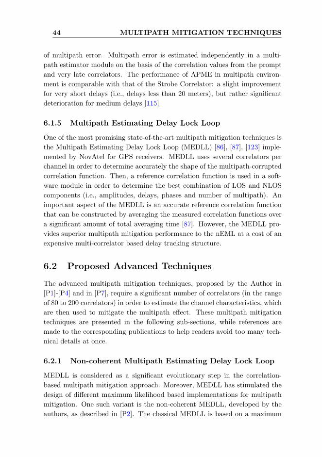
44 MULTIPATH MITIGATION TECHNIQUES
of multipath error. Multipath error is estimated independently in a multi-
path estimator module on the basis of the correlation values from the prompt
and very late correlators. The performance of APME in multipath environ-
ment is comparable with that of the Strobe Correlator: a slight improvement
for very short delays (i.e., delays less than 20 meters), but rather significant
deterioration for medium delays [115].
6.1.5 Multipath Estimating Delay Lock Loop
One of the most promising state-of-the-art multipath mitigation techniques is
the Multipath Estimating Delay Lock Loop (MEDLL) [86], [87], [123] imple-
mented by NovAtel for GPS receivers. MEDLL uses several correlators per
channel in order to determine accurately the shape of the multipath-corrupted
correlation function. Then, a reference correlation function is used in a soft-
ware module in order to determine the best combination of LOS and NLOS
components (i.e., amplitudes, delays, phases and number of multipath). An
important aspect of the MEDLL is an accurate reference correlation function
that can be constructed by averaging the measured correlation functions over
a significant amount of total averaging time [87]. However, the MEDLL pro-
vides superior multipath mitigation performance to the nEML at a cost of an
expensive multi-correlator based delay tracking structure.
6.2 Proposed Advanced Techniques
The advanced multipath mitigation techniques, proposed by the Author in
[P1]-[P4] and in [P7], require a significant number of correlators (in the range
of 80 to 200 correlators) in order to estimate the channel characteristics, which
are then used to mitigate the multipath effect. These multipath mitigation
techniques are presented in the following sub-sections, while references are
made to the corresponding publications to help readers avoid too many tech-
nical details at once.
6.2.1 Non-coherent Multipath Estimating Delay Lock Loop
MEDLL is considered as a significant evolutionary step in the correlation-
based multipath mitigation approach. Moreover, MEDLL has stimulated the
design of different maximum likelihood based implementations for multipath
mitigation. One such variant is the non-coherent MEDLL, developed by the
authors, as described in [P2]. The classical MEDLL is based on a maximum

6.2 Proposed Advanced Techniques 45
likelihood search, which is computationally extensive. The authors imple-
mented a non-coherent version of the MEDLL that reduces the search space
by incorporating a phase search unit, based on the statistical distribution of
multipath phases. It was shown in [P2] that the performance of this suggested
approach depends on the number of random phases considered; meaning that
the larger the number is, the better the performance will be. But this will
also increase the processing burden significantly. The results reported in [P2],
show that the non-coherent MEDLL provides very good performance in terms
of RMSE, but has a rather poor Mean-Time-to-Lose-Lock (MTLL) as com-
pared to the conventional DLL techniques.
6.2.2 Peak Tracking
Peak Tracking (PT) based techniques, namely PT based on 2nd order Differen-
tiation (PT(Diff2)) and PT based on Teager Kaiser (PT(TK)), were proposed
in [P2]. Both the techniques utilize the adaptive thresholds computed from
the estimated noise variance of the channel in order to decide on the correct
code delay. The adaptive thresholds are computed according to the equations
given in [P2]. After that, the advanced techniques generate the competitive
peaks which are above the computed adaptive thresholds. The generation
of competitive peaks for PT(Diff2) technique is shown in Fig. 6.1 in a two
path Nakagami-m fading channel. For each of the competitive peak, a deci-
sion variable is formed based on the peak power, the peak position and the
delay difference of the peak from the previous delay estimate. Finally, the PT
techniques select the peak which has the maximum weight as being the best
LOS candidate. It was shown in [P2] that PT(Diff2) has superior multipath
mitigation performance over PT(TK) in a two to five path Nakagami-m fading
channel.
6.2.3 Teager Kaiser Operator
The Teager Kaiser based delay estimation technique is based on the principle
of extracting the signal energy of various channel paths via a nonlinear TK
operator [45], [46]. The output ΨTK(x(n)) of the TK operator applied to a
discrete signal y(n), can be defined as [46]:
ΨTK(y(n)) = y(n− 1)y∗(n− 1) (6.1)
− 1
2[y(n− 2)y∗(n) + y(n)y∗(n− 2)]
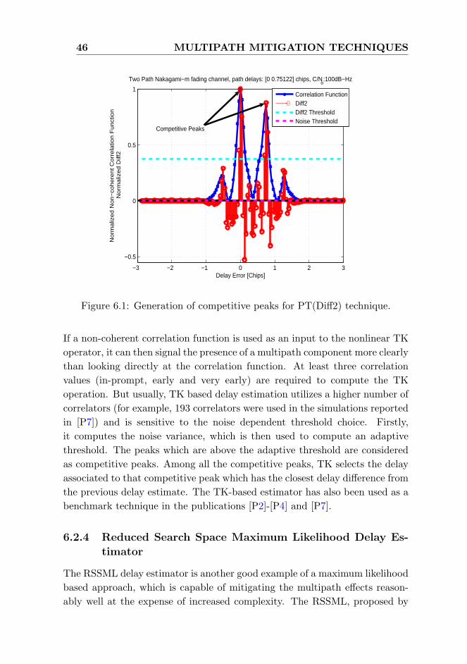
46 MULTIPATH MITIGATION TECHNIQUES
−3 −2 −1 0 1 2 3
−0.5
0
0.5
1
Two Path Nakagami−m fading channel, path delays: [0 0.75122] chips, C/No:100dB−Hz
Delay Error [Chips]
No
rma
lize
d N
on
−co
he
ren
t C
orr
ela
tion
Fu
nct
ion
No
rma
lize
d D
iff2
Correlation FunctionDiff2Diff2 ThresholdNoise Threshold
Competitive Peaks
Figure 6.1: Generation of competitive peaks for PT(Diff2) technique.
If a non-coherent correlation function is used as an input to the nonlinear TK
operator, it can then signal the presence of a multipath component more clearly
than looking directly at the correlation function. At least three correlation
values (in-prompt, early and very early) are required to compute the TK
operation. But usually, TK based delay estimation utilizes a higher number of
correlators (for example, 193 correlators were used in the simulations reported
in [P7]) and is sensitive to the noise dependent threshold choice. Firstly,
it computes the noise variance, which is then used to compute an adaptive
threshold. The peaks which are above the adaptive threshold are considered
as competitive peaks. Among all the competitive peaks, TK selects the delay
associated to that competitive peak which has the closest delay difference from
the previous delay estimate. The TK-based estimator has also been used as a
benchmark technique in the publications [P2]-[P4] and [P7].
6.2.4 Reduced Search Space Maximum Likelihood Delay Es-
timator
The RSSML delay estimator is another good example of a maximum likelihood
based approach, which is capable of mitigating the multipath effects reason-
ably well at the expense of increased complexity. The RSSML, proposed by

6.2 Proposed Advanced Techniques 47
the Author in [P4] and then further enhanced in [P7], attempts to compensate
the multipath error contribution by performing a nonlinear curve fit on the
input correlation function which finds a perfect match from a set of ideal refer-
ence correlation functions with certain amplitude(s), phase(s) and delay(s) of
the multipath signal. Conceptually, a conventional spread spectrum receiver
does the same thing, but for only one signal (i.e., the LOS signal). With the
presence of a multipath signal, RSSML tries to separate the LOS component
from the combined signal by estimating all the signal parameters in a maxi-
mum likelihood sense, which consequently achieves the best curve fit on the
received input correlation function. As mentioned in [P7], it also incorpo-
rates a threshold-based peak detection method, which eventually reduces the
code delay search space significantly. However, the downfall of RSSML is the
memory requirement which it uses to store the reference correlation functions.
In a multi-correlator based structure, the estimated LOS delay, theoret-
ically, can be anywhere within the code delay window range of ±τW chips,
though in practice, it is quite likely to have a delay error around the previ-
ous delay estimate. The code delay window range essentially depends on the
number of correlators (i.e., M) and the spacing between the correlators (i.e.,
∆) according to the following equation:
τW = ±(M − 1)
2∆ (6.2)
For example, in [P7], 193 correlators were used with a correlator spacing of
0.0208 chips, resulting in a code delay window range of ±2 chips with respect
to the prompt correlator. Therefore, the LOS delay estimate can be anywhere
within this ±2 chips window range. The ideal non-coherent reference corre-
lation functions are generated for up to L paths only for the middle delay
index (i.e., (M+12 )-th delay index; for M = 193, the middle delay index is
97). These ideal correlation functions for the middle delay index are gener-
ated off-line and saved in a look-up table in memory. In real-time, RSSML
reads the correlation values from the look-up table, translates the ideal ref-
erence correlation functions at the middle delay index to the corresponding
candidate delay index within the code delay window, and then computes the
Minimum Mean Square Error (MMSE) for that specific delay candidate. In-
stead of considering all possible LOS delays within a predefined code delay
window as delay candidates, the search space is first reduced to some com-
petitive peaks which are generated based on the computed noise thresholds as
explained in [P7]. This will eventually reduce the processing time required to
compute the MMSE (i.e., MMSE needs to be computed only for the reduced

48 MULTIPATH MITIGATION TECHNIQUES
search space). An example is shown in Fig. 6.2, where RSSML estimates a
best-fitted non-coherent correlation function at a cost of 3.6 ∗ 10−4 MMSE in
a two path Rayleigh channel with path delays [0 0.35] chips, path powers [0
-2] dB at a C/N0 of 50 dB-Hz.
−2 −1.5 −1 −0.5 0 0.5 1 1.5 2−0.2
0
0.2
0.4
0.6
0.8
1
1.2
Code Delays [Chips]
No
rmal
ized
Co
rrel
atio
n F
un
ctio
n
2 Path Rayleigh Channel, Path Delays:[ 0 0.35 ] Chips, CNR: 50 dBHz
Received Correlation FunctionEstimated Correlation FunctionResidual Error
Peak Threshold
Figure 6.2: Estimated and received non-coherent correlation functions in two
path Rayleigh channel, path delay: [0 0.35] chips, path power: [0 -2] dB, C/N0:
50 dB-Hz.
6.3 Proposed Simple Slope-based Technique
The Author proposed a simple slope-based multipath mitigation technique,
named as Slope-Based Multipath Estimator, in [P5]. Unlike the multipath
mitigation techniques discussed above, SBME does not require a huge number
of correlators, rather it only requires an additional correlator (as compared
to a conventional DLL) at the late side of the correlation function. In fact,
SBME is used in conjunction with a nEML tracking loop [P5]. It first derives
a multipath estimation equation by utilizing the correlation shape of the ideal
normalized correlation function, which is then used to compensate for the
multipath bias of a nEML tracking loop. The derivation of the multipath
estimation equation for BPSK modulated GPS L1 C/A signal can be found

6.4 Proposed Combined Techniques 49
in [P5]. It is reported in [P5] that SBME has superior multipath mitigation
performance to the nEML in a closely spaced two path channel model.
6.4 Proposed Combined Techniques
The motivation for having a combined approach is to ensure a better multipath
mitigation performance with a reasonable implementation complexity than
each single combining technique that is used to form the combined multipath
mitigation technique. In what follows, two such combining techniques are
presented, as proposed by the Author in [P6] and [P7], respectively.
6.4.1 C/N0-based Two-Stage Delay Tracker
A C/N0-based two-stage delay tracker is a combination of two individual track-
ing techniques, namely nEML and HRC (or MGD). The tracking has been
divided into two stages based on the tracking duration and the received signal
strength (i.e., C/N0). At the first stage of tracking (for about 0.1 seconds
or so), the two-stage delay tracker always starts with a nEML tracking loop,
since it begins to track the signal with a coarsely estimated code delay as ob-
tained from the acquisition stage. And, at the second or final stage of tracking
(i.e., when the DLL tracking error is around zero), the two-stage delay tracker
switches its DLL discriminator from nEML to HRC (or MGD), since HRC
(or MGD) has better multipath mitigation capability as compared to nEML.
While doing so, it has to be ensured that the estimated C/N0 level meets a
certain threshold set by the two-stage tracker. This is because of the fact that
HRC (or MGD) involves one (or two in case of MGD) more discrimination
than NEML, which makes its discriminator output much noisier than nEML.
It has been empirically found that a C/N0 threshold of 35 dB-Hz can be a
good choice, as mentioned in [P6]. Therefore, at this fine tracking stage, the
two-stage delay tracker switches from nEML to HRC (or MGD) only when
the estimated C/N0 meets the above criteria (i.e., C/N0 threshold is greater
than 35 dB-Hz).
An example non-coherent S-curve is shown in Fig. 6.3 for a CBOC(-)
modulated signal in a single path static channel [P6]. The nearest ambiguous
zero crossings for HRC (around ±0.16 chips) is much closer as compared to
that of nEML (around ±0.54 chips) in this particular case. This indicates the
fact that the probability of locking to any of the side peaks is much higher
for HRC than that of nEML, especially in the initial stage of tracking when

50 MULTIPATH MITIGATION TECHNIQUES
−2 −1.5 −1 −0.5 0 0.5 1 1.5 2−0.8
−0.6
−0.4
−0.2
0
0.2
0.4
0.6
0.8
Code Delay [chips]
No
n−
coh
ere
nt S
−cu
rve
CBOC(−) signal, Single Path Static Channel, ∆EL
=0.1 chips
nEMLHRC
Correct zero crossing
Nearest ambiguouszero crossings for HRC
Nearest ambiguouszero crossings for nEML
Figure 6.3: A non-coherent S-curve for CBOC(-) modulated single path static
channel [P6].
the code delay may not necessarily be near the main peak of the correlation
function. This is the main motivation to choose a nEML tracking at the initial
stage for a specific time duration (for example, 0.1 seconds or so). This will
eventually pull the delay tracking error around zero after the initial stage.
6.4.2 TK operator combined with a nEML DLL
A combined simplified approach with the TK operator and a nEML DLL was
implemented in [P7], in order to justify the feasibility of having a nEML dis-
crimination after the TK operation on the non-coherent correlation function.
In this combined approach, the TK operator is first applied to the non-coherent
correlation function, and then nEML discrimination is applied to the TK out-
put. The motivation for this combined approach comes from the fact that -
when we apply the TK operation to the non-coherent correlation function, it
usually makes the main lobe of the non-coherent correlation function (after
TK operation) much steeper than before. This eventually reduces the effect
of multipath in case of TK based nEML (TK+nEML) as compared to nEML.

Chapter 7
Experimental Analysis
In this chapter, the performance of some of the multipath mitigation tech-
niques are evaluated in different simulation models, i.e., the semi-analytical
simulation for the Running Average Error (RAE) analysis, the Matlab-based
simulation in a multipath fading channel and the simulation carried out in
the TUT Galileo E1 Simulink simulator. Each simulation model is briefly de-
scribed first before presenting the results obtained with it. It is worth to men-
tion here that more simulation results have been presented in the publications
[P1]-[P8] and this chapter only provides a summary of the main findings re-
garding various multipath mitigation techniques and of the main performance
criteria used within the scope of this thesis.
7.1 Semi-analytical Simulation
The most typical way to evaluate the performance of a multipath mitigation
technique is via Multipath Error Envelopes (MEE). Typically, two paths, ei-
ther in-phase or out-of-phase, are assumed to be present, and the multipath
errors are computed for multipath delays up to 1.2 chips at maximum, since
the multipath errors become less significant after that. The upper multipath
error envelope can be obtained when the paths are in-phase and the lower
multipath error envelope when the paths are out-of-phase (i.e., 180 phase dif-
ference). In MEE analysis, several simplifying assumptions are usually made
in order to distinguish the performance degradation caused by the multipath
errors only. Such assumptions include zero Additive-White-Gaussian-Noise
(AWGN), ideal infinite-length PRN codes, and zero residual Doppler. Under
these assumptions, the correlation Rrx(τ) between the reference code of the
51
52 EXPERIMENTAL ANALYSIS
modulation type MOD (for example, BPSK or CBOC(-)) and the received
MOD-modulated signal via an L-path channel can be written as:
Rrx(τ) =L∑l=1
αlejθlRMOD(τ − τl) (7.1)
where αl, θl, τl are the amplitude, phase, and delay, respectively, of the l-th
path; and RMOD(τ) is the auto-correlation function of a signal with the mod-
ulation type MOD. The analytical expressions for MEEs become complicated
in the presence of more than two paths due to the complexity of channel inter-
actions. Therefore, an alternative Monte-Carlo simulation-based approach is
presented here, in accordance with [P7], for multipath error analysis in more
than one path scenarios (i.e, for L ≥ 2). First, a sufficient number of ran-
dom realizations, Nrandom are generated (i.e., in the simulation, we choose
Nrandom equals to 1000), and then we look at the absolute mean error for each
path delay over Nrandom points. The objective is to analyze the multipath
performance of some of the proposed advanced techniques along with some
conventional DLLs in the presence of more than two channel paths, which
may occur in urban or indoor scenarios.
The following assumptions are made while running the simulation for gen-
erating the RAE curves [49]. According to [49], RAE is computed from the
area enclosed within the multipath error and averaged over the range of the
multipath delays from zero to the plotted delay values. In the simulation, the
channel follows a decaying Power Delay Profile (PDP), which can be expressed
by the equation:
αl = αl exp−µ(τl−τ1), (7.2)
where (τl−τ1) = 0 for l > 1, µ is the PDP coefficient (assumed to be uniformly
distributed in the interval [0.05; 0.2], when the path delays are expressed in
samples). The channel path phases θl are uniformly distributed in the interval
[0; 2π] and the number of channel paths L is uniformly distributed between 2
and Lmax, where Lmax is set to 5 in the simulation. A constant successive path
spacing xct is chosen in the range [0; 1.167] chips with a step of 0.0417 chips
(which defines the multipath delay axis in the RAE curves). It is worth to
mention here that the number of paths is reduced to only one LOS path when
xct = 0. The successive path delays can be found using the formula τl = lxctin chips. Therefore, for each channel realization (which is a combination of
amplitudes α = α1, . . . , αL, phases θ = θ1, . . . , θL, fixed path spacings, and
the number of channel paths L), a certain LOS delay is estimated τ1(α, θ, L)

7.1 Semi-analytical Simulation 53
from the zero crossing of the discriminator function (i.e., D(τ) = 0), when
searched in the linear range of D(τ) in case of conventional DLLs, or directly
from the auto-correlation function in case of advanced multi-correlator based
techniques. The estimation error due to multipath is τ1(α, θ, L)− τ1, where τ1is the true LOS path delay. The RAE curves are generated in accordance with
[49]. RAE is actually computed from the area enclosed within the multipath
error and averaged over the range of the multipath delays from zero to the
plotted delay values. Therefore, in order to generate the RAE curves, the
Absolute Mean Error (AME) is computed for all Nrandom random points via
eqn. 7.3:
AME(xct) = mean(∣∣∣τ1(α, θ, L)− τ1
∣∣∣), (7.3)
where AME(xct) is the mean of the absolute multipath error for the successive
path delay xct. Now, the running average error for each particular delay in
the range [0;1.167] chips can be computed as follows:
RAE(xct) =
i∑i=1
AME(xct)
i,
(7.4)
where i is the successive path delay index, and RAE(xct) is the RAE for the
successive path delay xct.
The RAE curves for CBOC(-) modulated Galileo E1C signal (i.e., pilot
channel) is shown in Fig. 7.1. It is obvious from Fig. 7.1 that the proposed
RSSML and PT(Diff2) show the best performance in terms of RAE as com-
pared to other techniques in this noise-free two to five paths static channel
model. Among other techniques, TK+nEML showed very good performance
followed by SBME, HRC and nEML. The SBME coefficient and the late slope
at very late spacing of 0.0833 chips were determined according to [P5] for a
24.552 MHz front-end bandwidth (double-sided). For the above configuration,
the SBME coefficient is 0.007 and the late slope is −4.5.
It is worth to mention here that the RAE analysis is quite theoretical
from two perspectives: firstly, the delay estimation is a one-shot estimate, and
does not really include any tracking loop in the process; and secondly, the
analysis is usually carried out with an ideal noise free assumption. These facts
probably explain the reason why an algorithm which performs very well with
respect to RAE may not necessarily provide the same performance in a more
realistic closed loop fading channel model, especially in the presence of more
than two channel paths. However, MEE or RAE analysis has been widely used

54 EXPERIMENTAL ANALYSIS
0 0.2 0.4 0.6 0.8 1 1.2 1.40
0.5
1
1.5
2
2.5
3
3.5
4CBOC(−) signal, 2 to 5 paths, BW 24.552 MHz
Multipath delay [chips]
Cod
e tr
acki
ng e
rror
[met
ers]
nEMLHRCTK+nEMLPT(Diff2)SBMERSSML
Figure 7.1: Running average error curves for CBOC(-) modulated Galileo E1C
signal.
by the research community as an important tool for analyzing the multipath
performance due to simpler implementation, and also due to the fact that it
is hard to isolate multipath from other GNSS error sources in real life.
7.2 Matlab-based Simulation
Simulation has been carried out in closely spaced multipath environments
for CBOC(-) modulated Galileo E1C (i.e., pilot channel) signal for a 24.552
MHz front-end bandwidth. The simulation profile is summarized in Table 7.1.
Rayleigh fading channel model is used in the simulation, where the number
of channel paths follows a uniform distribution between two and five. The
successive path separation is random between 0.02 and 0.35 chips. The channel
paths are assumed to obey a decaying PDP according to Eqn. 7.2, where
(τl − τ1) = 0 for l > 1, and the PDP coefficient µ = 0.1. The received signal is
sampled such that there are 48 samples per chip. The received signal duration
is 800 milliseconds (ms) or 0.8 seconds for each particular C/N0 level. The
tracking errors are computed after each Nc∗Nnc ms (in this case, Nc∗Nnc = 20
ms) interval. In the final statistics, the first 600 ms are ignored in order to
remove the initial error bias that may come from the delay difference between
the received signal and the locally generated reference code. Therefore, for
the above configuration (i.e., code loop filter parameters and the first path

7.2 Matlab-based Simulation 55
Table 7.1: Simulation profile description
Parameter Value
Channel model Rayleigh fading channel
Number of paths between 2 to 5
Path Power Decaying PDP with µ = 0.1
Path Spacing Random between 0.02 and 0.35 chips
Path Phase Random between 0 and 2π
Samples per Chip, Ns 48
E-L Spacing, ∆EL 0.0833 chips
Number of Correlators, M 1931
Double-sided Bandwidth, BW 24.552 MHz
Filter Type Finite Impulse Response (FIR)
Filter Order 6
Coherent Integration, Nc 20 ms
Non-coherent Integration, Nnc 1 block
Initial Delay Error ± 0.1 chips
First Path Delay 0.2 chips
Code Tracking Loop Bandwidth 2 Hz
Code Tracking Loop Order 1st order
delay of 0.2 chips), the left-over tracking errors after 600 ms are mostly due to
the effect of multipath. The simulation has been carried out for 100 random
realizations, which give a total of 10*100=1000 statistical points, for each
C/N0 level. The RMSE of the delay estimates are plotted in meters, by using
the relationship:
RMSEm = RMSEchipscTc (7.5)
where c is the speed of light, Tc is the chip duration, and RMSEchips is the
RMSE in chips.
RMSE vs. C/N0 plot for the given multipath channel profile is shown in
Fig. 7.2. It can be seen from Fig. 7.2 that the proposed RSSML clearly
achieves the best multipath mitigation performance in this two to five paths
closely spaced multipath channel. Among other techniques, PT(Diff2) and
HRC have better performance only in good C/N0 (around 40 dB-Hz and on-
wards). It can also be observed that the proposed SBME and TK+nEML do
1Not all the correlators are used in all the tracking algorithms. For example, nEML only
requires 3 correlators.

56 EXPERIMENTAL ANALYSIS
not bring any advantage in the tracking performance as compared to nEML
in this multipath fading channel model. Here also, the SBME coefficient and
the late slope were set to 0.007 and −4.5, respectively.
30 35 40 450
10
20
30
40
50
60
70
C/N0 [dB−Hz]
RM
SE
[m
ete
rs]
CBOC(−) signal, 2 to 5 paths, BW 24.552 MHz
nEMLHRCTK+nEMLPT(Diff2)SBMERSSML
Figure 7.2: RMSE vs. C/N0 plot for CBOC(-) modulated Galileo E1C signal
in two to five path Rayleigh fading channel.
7.3 Simulink-based TUT Galileo E1 Signal Simula-
tion
All the simulations reported in [P6] were carried out in the TUT Galileo E1
signal simulator. The TUT Galileo E1 signal simulator was developed in a
Simulink-based platform at Tampere University of Technology, Finland. The
basic version of the Simulink model was created by a former DCE researcher,
Hu Xuan in early 2009. Since then, the Simulink model has been extended by
the Author by adding several signal processing blocks according to the nature
and objective of the research. An overview of the TUT Galileo E1 signal
simulator with a tracking-only feature is presented herein in accordance with
[P6]. In [P6], a tracking-only model was utilized since the objective was to
analyze the performance of the proposed C/N0-based two-stage delay tracker
in multipath scenarios. The tracking-only Simulink model consists of four
blocks, as shown in Fig. 7.3. A brief overview of these blocks is presented in
the following.
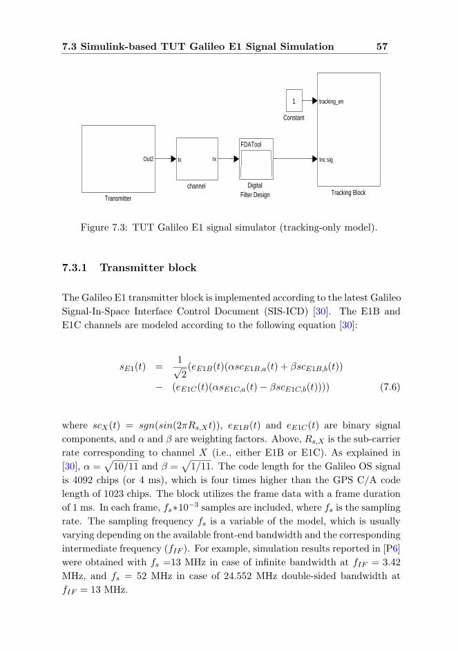
7.3 Simulink-based TUT Galileo E1 Signal Simulation 57
channel
tx rx
Transmitter
Out2
Tracking Block
tracking_en
Inc sig
DigitalFilter Design
FDATool
Constant
1
Figure 7.3: TUT Galileo E1 signal simulator (tracking-only model).
7.3.1 Transmitter block
The Galileo E1 transmitter block is implemented according to the latest Galileo
Signal-In-Space Interface Control Document (SIS-ICD) [30]. The E1B and
E1C channels are modeled according to the following equation [30]:
sE1(t) =1√2(eE1B(t)(αscE1B,a(t) + βscE1B,b(t))
− (eE1C(t)(αsE1C,a(t)− βscE1C,b(t)))) (7.6)
where scX(t) = sgn(sin(2πRs,Xt)), eE1B(t) and eE1C(t) are binary signal
components, and α and β are weighting factors. Above, Rs,X is the sub-carrier
rate corresponding to channel X (i.e., either E1B or E1C). As explained in
[30], α =√
10/11 and β =√
1/11. The code length for the Galileo OS signal
is 4092 chips (or 4 ms), which is four times higher than the GPS C/A code
length of 1023 chips. The block utilizes the frame data with a frame duration
of 1 ms. In each frame, fs∗10−3 samples are included, where fs is the sampling
rate. The sampling frequency fs is a variable of the model, which is usually
varying depending on the available front-end bandwidth and the corresponding
intermediate frequency (fIF ). For example, simulation results reported in [P6]
were obtained with fs =13 MHz in case of infinite bandwidth at fIF = 3.42
MHz, and fs = 52 MHz in case of 24.552 MHz double-sided bandwidth at
fIF = 13 MHz.
58 EXPERIMENTAL ANALYSIS
7.3.2 Channel block
The multipath signals and the complex AWGN are modeled in the channel
block according to the following equation:
rE1(t) =L∑l=1
αl(t)sE1(t− τl) + η(t) (7.7)
Here, rE1(t) is the received E1 signal at the output of the channel block; αl
and τl are the path gain and path delay for the lth path, respectively; and η(t)
is the complex AWGN.
7.3.3 Front-end filter block
Simulink’s ‘Digital Filter Design’ toolbox is used to design the front-end filters
in all the simulations (where finite front-end bandwidth is assumed) reported
in [P6]. A 6th order Chebyshev type I filter with a 24.552 MHz double-sided
bandwidth is used in the simulation.
7.3.4 Tracking block
The tracking block consists of three major blocks: ‘Carrier wipe-off block’,
‘Code NCO block’, and ‘Dual channel correlation and discriminators block’,
as described in detail in [P6] and [110]. The incoming signal is down converted
to the baseband in the ‘Carrier Wipe-Off’ block. After the carrier wipe-off,
the real part and the imaginary part of the complex signal are separated
as the in-phase channel (or, I channel) and the quad-phase channel (or, Q
channel) in baseband. The ‘Code NCO’ block considers the estimated code
phase error from the DLL in order to shift the code phase accordingly. This
block generates four signals as output: the adjusted E1B and E1C replicas,
the trigger enabling signal and the shifted NCO phase. The trigger enabling
signal is used in conjunction with ‘tracking en’ which eventually enables both
FLL/PLL and DLL blocks of the E1B and E1C channels (when both the
variables are set to 1). Both the code and carrier NCOs were implemented
using a C-language based S-function, the details of which are not addressed
here for the sake of compactness. The variable ‘tracking en’ is intentionally set
to 1 in order to run the tracking block continuously. In addition, the initially
estimated frequency and the initially estimated code delay, which are to be
used by the tracking block, are also set such that the initial frequency error
is less than 88 Hz, and the initial code delay error is less than 0.1 chips. The

7.3 Simulink-based TUT Galileo E1 Signal Simulation 59
reason for such a scheme is to run the tracking block independently in order
to be able to calculate the tracking error in terms of RMSE.
C/N0 Estimation
At the tracking stage, the C/N0 estimation is performed based on the ratio of
the signal’s wideband power to its narrowband power as discussed in [92]. In
this method, the power of the signal is computed over a wide bandwidth with
a relatively short coherent integration time and over a narrow bandwidth with
a longer coherent integration time. In the simulation, the wideband power is
computed after 4 ms of coherent integration (after each code epoch length),
and the narrowband power is computed after 16 ms of coherent integration in
order to estimate the carrier-to-noise density ratio for each particular channel.
7.3.5 Simulation Results
Fig. 7.4 shows the RMSE versus C/N0 plots in a two path static channel model
with path delays [0.1 0.2] chips and with path powers [0 -3] dB in a 24.552
Figure 7.4: RMSE vs. C/N0 plots in a two path static channel in a 24.552
MHz double-sided bandwidth [P6].

60 EXPERIMENTAL ANALYSIS
MHz double-sided bandwidth. Both HRC and MGD lock to a side peak at 35
dB-Hz, whereas the two-stage delay trackers can avoid the false lock problem
and have similar performance like nEML (or NEML) at 35 dB-Hz C/N0 and
lower. When the estimated C/N0 is above 35 dB-Hz (from 40 dB-Hz and
onwards in the plots), the two-stage delay tracker switches to HRC (or MGD)
at the fine tracking stage (after 0.1 seconds of tracking). This eventually leads
to a better overall tracking performance as compared to tracking with a single
technique (either nEML or HRC).
Chapter 8
Summary of Publications
The second part of this compound thesis consists of eight publications [P1]-
[P8]: five articles published in international conferences, two articles in in-
ternational journals and one article in a renowned GNSS-related magazine.
None of these publications has been used (or planned to be used) as a part of
any other dissertation. In this chapter, the results of the publications and the
contributions of the Author of this thesis are summarized.
8.1 Overview of the Publication Results
A novel Peak Tracking algorithm was proposed in [P1] as a delay estimation
technique, which utilizes the advantages of both feedforward and feedback
techniques and thereby improves the delay estimation accuracy. The pro-
posed technique combines the feedback (as used by a conventional DLL) and
the feedforward techniques in such a way that it increases the delay estimation
accuracy while preserving a good mean-time-to-lose-lock. Simulation results
in Nakagami-m multipath fading channel model were presented in order to
compare the performance of the proposed technique with some of the conven-
tional feedback DLLs along with few other promising feedforward techniques,
previously studied in [73] and [77]. It was shown in [P1] that the proposed PT
algorithm distinctively shows the best performance in the presented Nakagami-
m fading channel model at moderate to high C/N0 in terms of RMSE, while
preserving an MTLL close to that of feedback DLLs.
In [P2], two variants of the basic Peak Tracking based delay estimation
technique were proposed and implemented for GPS and Galileo signals. Peak
Tracking with 2nd order Differentiation PT(Diff2) and Peak Tracking with
61

62 SUMMARY OF PUBLICATIONS
Teager Kaiser PT(TK) operator are the two variants of PT, which utilize the
inherent advantages of both the feedback and feedforward structures. We re-
mark here that the basic PT introduced in [P1] was using only the second order
derivative estimates and it is valid only for the SinBOC(1,1) modulated sig-
nal, while the enhanced PT from [P2] has been extended to BPSK modulation
and includes also a TK-based approach. In [P2], the authors also proposed
an Improved Early-Late-Slope multipath elimination technique and a unique
non-coherent implementation of the Multipath Estimating Delay Locked Loop,
where the phase information was searched via statistical assumptions. Exten-
sive simulation results in both limited and unlimited receiver bandwidths were
presented for nine different multipath mitigation techniques. It was shown that
among all the considered techniques, the best trade off between RMSE and
MTLL was achieved by PT(Diff2), which reduced the delay estimation error
considerably at moderate-to-high C/N0, while preserving a better MTLL com-
pared with other feedforward techniques. It was also shown that our imple-
mentation of the non-coherent MEDLL offered the best multipath mitigation
performance in RMSE sense, but suffered from poor MTLL.
The advanced multi-correlator based feedforward techniques, previously
proposed by the authors in [P1] and [P2], were implemented in closed loop
(or feedback) model (i.e., in the presence of an NCO and a loop filter) in
publication [P3]. The multipath performance of some promising feedforward
techniques (i.e., PT(Diff2) and TK) along with the conventional DLLs were
presented in terms of RAE and RMSE for three different signal modulations,
including the newly proposed MBOC modulation. It was shown in [P3] that
the advanced feedforward techniques showed much better multipath mitiga-
tion performance than the traditional DLLs at moderate-to-high C/N0 for all
three modulated signals (namely, BPSK, SinBOC(1,1) and MBOC) in both
closed and open loop models. It was also shown that - under the given circum-
stances, the closed loop and open loop models provide very similar tracking
performance. The equivalence between closed loop (feedback) and open loop
(feedforward) delay tracking models has not been proved before to the best
of the Author’s knowledge. The multipath improvement of the MBOC sig-
nal over BPSK and SinBOC(1,1) signals was also evident from the simulation
results.
A maximum likelihood based multipath mitigation technique, namely Re-
duced Search Space Maximum Likelihood delay estimator was proposed in
[P4]. The proposed RSSML is capable of mitigating the multipath effects rea-
sonably well at the expense of increased complexity. The RSSML attempts

8.1 Overview of the Publication Results 63
to compensate the multipath error contribution by performing a nonlinear
curve fit on the input correlation function which finds a perfect match from a
set of ideal reference correlation functions with certain amplitude(s), phase(s)
and delay(s) of the multipath signal. It also incorporates a threshold-based
peak detection method, which eventually reduces the code delay search space
significantly. However, the downfall of RSSML is the memory requirement
which it uses to store the reference correlation functions. The multipath per-
formance of the newly proposed technique along with the conventional DLLs
and the other feedforward techniques was presented in a multipath Rayleigh
fading channel model. Here also, BPSK and SinBOC(1,1) modulations were
considered along with the CBOC modulation selected for the Galileo E1 sig-
nal. It was shown that the RSSML, in general, achieved the best multipath
mitigation performance in RMSE sense in a two path Rayleigh fading model.
In [P5], a novel multipath mitigation technique, Slope-Based Multipath
Estimator was proposed and tested for Galileo E1 signal and for GPS L1 C/A
signal. This new multipath mitigation technique is capable of mitigating the
short-delay multipath (i.e., multipath delays less than 0.35 chips) quite well
compared to other state-of-the-art mitigation techniques, such as nEML and
HRC. The proposed SBME first derives a multipath estimation equation by
utilizing the correlation shape of the ideal normalized correlation function of
a BPSK- or CBOC-modulated signal, which is then used to compensate for
the multipath bias of a nEML tracking loop. SBME requires an additional
correlator at the late side of the correlation function compared to the basic
nEML structure and it is used in-conjunction with a nEML tracking loop.
The multipath performance of the newly proposed technique along with the
conventional DLLs was studied in terms of theoretical RAE and the simulated
RMSE for short-delay multipath scenarios. It was shown that SBME provided
the best overall performance as compared to nEML and HRC in short-delay
multipath scenarios.
In publication [P6], a C/N0-based two-stage delay tracking technique was
proposed and implemented in the Simulink-based TUT Galileo E1 signal simu-
lator. The false lock problem of the classical HRC and MGD was addressed in
case of the Galileo E1 OS signal. The multipath performance of the proposed
two-stage delay trackers was presented along with their respective counterparts
in two different bandwidth assumptions. It was shown that the two-stage delay
trackers solve the false lock problem while preserving the multipath mitiga-
tion performance of HRC or MGD at good C/N0 (i.e., from 40 dB-Hz and
onwards).

64 SUMMARY OF PUBLICATIONS
The novel RSSML delay estimator, as initially proposed in [P4], was en-
hanced and optimized for more than two path scenarios in [P7]. The RSSML
delay estimator, as presented in [P7], requires a large set of correlation func-
tions only for the prompt correlator, not for all possible delays in a predefined
code delay window range, and thereby, reduces the memory requirement sig-
nificantly. In addition, the RSSML was also adapted for a finite bandwidth
assumption for any number of paths up to four. Moreover, in [P7], a combined
simplified approach with the Teager Kaiser and the narrow EML was proposed
and implemented in order to justify the feasibility of having a nEML discrim-
ination after the TK operation on the non-coherent correlation function. The
multipath performance of the proposed techniques along with the state-of-
the-art DLLs and other advanced techniques was presented in terms of RAE
and RMSE. The performance of these techniques were analyzed for the newly
defined CBOC modulation along with the existing BPSK and SinBOC(1,1)
modulations. It was shown that RSSML, in general, achieved the best mul-
tipath mitigation performance for all three different modulations in a two-to-
four path closely spaced multipath scenario. However, the proposed RSSML
increases the receiver complexity, since it is based on a multi-correlator based
delay tracking structure, and at the same time, it requires a good amount of
memory to keep the reference non-coherent correlation functions available for
the MMSE computation. Therefore, the RSSML and other advanced multi-
path mitigation techniques are more suitable for professional high-end receivers
(i.e., receivers with large front-end bandwidths and high sampling frequencies,
offering the possibility of having many closely-spaced correlators at the code
tracking stage); whereas for mass-market receivers, the nEML and the HRC
still provide the best trade off between performance and complexity.
In publication [P8], a novel spectral analysis of different types of MBOC
modulation was presented in an unified manner. The spectral differences be-
tween CBOC and TMBOC variants were quantized in terms of C/N0 dete-
rioration in order to analyze the impact of these differences on the system
performance. It was shown that the CBOC(-) variant is the best variant in
terms of multipath mitigation and tracking error variance, while TMBOC
behaves better than CBOC in terms of detection error probability of the de-
modulated data. It was also shown in [P8] that the spectral differences and
the differences between CBOC and TMBOC variants are rather small in terms
of the considered performance criteria, especially when the receiver bandwidth
is not very high.

8.2 Author’s Contribution to the Publications 65
8.2 Author’s Contribution to the Publications
The research work for this thesis was carried out at the Department of Com-
munications Engineering (DCE) in Tampere University of Technology (TUT),
as part of the Tekes funded research projects “Advanced Techniques for Per-
sonal Navigation (ATENA)” during the years 2006 - 2007 and “Future GNSS
Applications and Techniques (FUGAT)” during the years 2007 - 2009, of the
Academy of Finland funded research project “Digital Signal Processing Algo-
rithms for Indoor Positioning Systems” during the years 2008 - 2011, of the
EU FP6 research project “Galileo Receiver for Mass Market (GREAT)” dur-
ing the years 2006 - 2008, and of the EU FP7 research project “Galileo Ready
Advanced Mass Market Receiver (GRAMMAR)” during the years 2009 - 2011.
During the work, the Author has been a member of an active research group
involved in analyzing and developing signal processing techniques for GNSS
receivers. Many of these ideas have originated in formal group meetings as well
as in casual discussions within the group, and some of the simulation mod-
els (built in Matlab and Simulink) have been designed in cooperation with
the co-authors. Therefore, the Author’s contribution cannot be separated
completely from the contributions of the co-authors. However, the Author’s
contribution to all of the publications included in this thesis has been essen-
tial in the sense that he developed the main theoretical framework, developed
new techniques, performed the simulations, analyzed the performance, and
prepared the manuscripts where he is the main author, and a good part of
the manuscript where he is the second author. The main contributions of the
Author to the publications are summarized as follows.
In [P1], the Author developed the novel Peak Tracking technique in a
open loop model (i.e., without the presence of the NCO and the loop filter),
elaborated the operating principles of the developed technique, performed the
simulations and analyzed the multipath performance with some well-known
feedback and feedforward techniques. The manuscript was also fully written
by the Author. The novel idea of having a combined feedback and feedforward
strategy was the result of numerous discussions with Dr. Elena Simona Lohan.
The co-authors helped to build the simulation model for the Nakagami-m
fading channel model and also implemented the Matched Filter technique used
in the simulations for performance comparison.
In [P2], the Author proposed and implemented a bunch of multipath mit-
igation techniques in close cooperation with the co-authors. Among them,
PT(Diff2), PT(TK), and IELS were developed entirely by the Author, whereas

66 SUMMARY OF PUBLICATIONS
the non-coherent MEDLL was implemented by the co-authors, which was fur-
ther optimized by the Author for a better multipath performance in a fading
channel model. The idea of applying a 2nd order differentiation on the corre-
lation function was first introduced to the Author by Dr. Ridha Hamila. The
Author carried out all the simulations and wrote most part of the manuscript,
whereas the co-authors cooperated to develop the simulation model.
A closed loop model for evaluating the performance of various multipath
mitigation techniques was implemented in publication [P3] together with the
co-authors of the paper. The co-author Xuan Hu built the NCO model in
Matlab, which was then used to run the simulations. The Author adapted
the feedforward techniques to the closed loop model, performed all the re-
quired simulations, analyzed the multipath performance of various tracking
techniques, and wrote the manuscript.
In [P4], the Author developed the proposed maximum likelihood based
multipath mitigation technique RSSML, elaborated the implementation re-
lated issues of the new technique, performed the simulations, analyzed the
multipath performance of the proposed technique along with few other tech-
niques and wrote the manuscript. The discussions with the co-authors helped
in choosing the performance criteria and the benchmark algorithms.
In [P5], the Author proposed the novel slope-based multipath mitigation
technique for two GNSS signals (i.e., Galileo E1 signal and GPS L1 C/A
signal), derived the multipath equation in an infinite front-end bandwidth
case, performed the simulations, and wrote the manuscript. The development
of such a novel technique was the outcome of several productive discussions
with the co-authors.
In [P6], the Author proposed a C/N0-based two-stage delay tracking tech-
nique for the Galileo E1 signal, implemented a C/N0 estimator and the pro-
posed tracking structure in the TUT Galileo E1 signal simulator and wrote
most parts of the manuscript. The simulations were carried out in cooperation
with the co-authors.
In [P7], the Author enhanced and optimized the RSSML delay estima-
tor and proposed a combined delay tracking method, namely the combined
TK plus nEML technique. In addition, the Author developed the simulation
model, performed the simulations, analyzed the performance of various mul-
tipath mitigation techniques and wrote the manuscript. The discussions with
the co-author helped in choosing the performance criteria and the benchmark
techniques.
In [P8], the Author analyzed the impact of spectral differences between

8.2 Author’s Contribution to the Publications 67
various CBOC and TMBOC variants on receiver performance in terms of mul-
tipath mitigation via MEE curves as well as via Monte Carlo simulations. The
Author also carried out the simulations required for multipath performance
assessment. The co-authors derived the exact frequency-domain form of the
PSD for CBOC and TMBOC waveforms. The manuscript was written jointly
with the co-authors.

68 SUMMARY OF PUBLICATIONS

Chapter 9
Conclusions
In this thesis, the Author particularly addressed the challenges encountered
by a GNSS signal due to multipath propagation. In this regard, the Author
analyzed a wide range of correlation-based multipath mitigation techniques in
static and fading multipath channels for a group of GNSS signals, more specif-
ically, the interoperable civilian signals from two different navigation systems,
i.e., Galileo E1 signal and the modernized GPS L1C signal, along with the
existing GPS L1 C/A signal used in almost all the receivers available today.
During the process of analyzing these techniques, the Author also proposed
several novel multipath mitigation techniques applicable for a wide range of
applications (from simple low-cost mass-market receivers to a relatively com-
plex expensive high-end receivers).
In Chapter 1, the challenges, the motivation, the prior art, the scope,
and the main contributions of the thesis were discussed. Chapter 2 presented
briefly the principles of satellite-based positioning, provided an overview of
current and future GNSSs, and discussed the major application areas for GNSS
users. The signal and channel model were described in Chapter 3 with respect
to BOC modulation and its variants.
After providing a brief introduction on GNSS receiver structure in Chapter
4 with particular attention to signal acquisition and tracking, the Author
introduced a multi-correlator based delay tracking structure for the advanced
multipath mitigation techniques in order to take decision on the correct code
delay. As shown in [P7], the multi-correlator based tracking structure offers
a superior tracking performance compared to the traditional nEML DLL at
the cost of higher number of correlators. Therefore, this structure is only
suitable for professional high-end receivers (i.e., receivers with large front-end
69
70 CONCLUSIONS
bandwidths and high sampling frequencies, offering the possibility of having
many closely-spaced correlators at the code tracking stage).
The various error sources for satellite-based positioning technology were
briefly described in Chapter 5 with a major focus on multipath error, as being
the most challenging error due to its uncorrelated behavior. The effects of
various signal and receiver parameters on signal tracking performance, and the
relation between these parameters and the multipath error were also discussed
here to better understand the research problem addressed in this thesis.
After providing a detailed overview of some of the most promising state-of-
the-art multipath mitigation techniques in Chapter 6, the Author presented
the novel multipath mitigation techniques, which were originally proposed
by the Author in various publications from [P1]-[P7]. The performance of
these multipath mitigation techniques were evaluated in terms of different
performance criteria, such as running average error and root-mean-square error
in different simulation models as described in Chapter 7. A general comparison
of all these techniques is summarized briefly in Fig. 9.1, considering the issues
related to multipath performance and required implementation complexity.
The implementation complexity of any multipath mitigation technique
mainly depends on the correlation structure and the implementation issues
concerning channel estimation, correlator requirement, required number of
mathematical operations, memory requirement and so on. The advanced mit-
igation techniques are usually complex, since they generally utilize a large
number of correlators (i.e., in the range of 80 to 200 correlators) for chan-
nel estimation, which are then used to estimate the first arriving path delay.
Among the advanced techniques, the proposed RSSML is the most complex
one, since it requires a large set of reference correlation functions as a-priori
information. Among the other proposed techniques, SBME and the C/N0-
based two-stage delay tracker have the least implementation complexity, since
they only require few correlators for the LOS delay estimation. Also, the TK
with nEML has moderate implementation complexity, as it applies the TK
operation before the nEML discrimination.
Among the proposed advanced techniques, RSSML, in general, achieved
the best multipath mitigation performance in moderate-to-high C/N0 scenar-
ios (for example, 30 dB-Hz and onwards). The other advanced techniques,
such as PT(Diff2) and non-coherent MEDLL showed good multipath mitiga-
tion performance only in high C/N0 scenarios (for example, 40 dB-Hz and
onwards). The proposed simple technique SBME offered superior multipath
mitigation performance to the well-known nEML DLL at the cost of an ad-
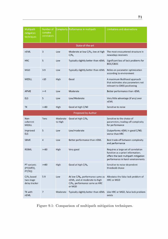
71
Figure 9.1: Comparison of multipath mitigation techniques.

72 CONCLUSIONS
ditional correlator. The proposed combined technique, C/N0-based two-stage
delay tracker offered a better tracking accuracy than its individual counterpart
(i.e., nEML and HRC), and also alleviated the false lock problem of HRC and
MGD. The other combining technique TK with nEML DLL showed slightly
better performance than nEML, but it also suffered from the false lock problem
like HRC and MGD.
To summarize the discussion, it can be said that RSSML and other ad-
vanced multipath mitigation techniques proposed in this thesis are more suit-
able for professional receivers due to their relatively high complexity; whereas
for mass-market receivers, SBME and the C/N0-based two-stage delay tracker
are the best trade-off between performance and complexity.
Parts of the Author’s work have been used as a basis of further research
in other research units over the world. For example, the multipath mitigation
techniques proposed in [P2] have been cited in [23], [81], [82], [84], [100], [107],
[108], [109] and [132]. The SBME multipath mitigation technique presented in
[P5] and the C/N0-based two-stage delay tracker presented in [P6] have also
been employed and evaluated in [56]. An enhanced version of SBME has been
selected to be implemented in the prototype receiver of the EU FP7 research
project ‘GRAMMAR’ [44].
As the GNSS research area is fast evolving with many potential appli-
cations, it remains a challenging topic for future research to investigate the
feasibility of the proposed novel techniques with the multitude of signal modu-
lations, spreading codes, and spectrum placements that are (or are to be) pro-
posed. Although the simulation tools used in this thesis were designed to meet
the actual conditions, it would be really meaningful to analyze the performance
of some of the proposed most promising multipath mitigation techniques (for
example, RSSML, PT and SBME) on some measurement-based satellite-to-
receiver multipath channel models, for example, the multipath channel models
proposed in [70], [71], [117] and [118].
Bibliography
[1] Apple webpage. http:// www.apple.com. Apple Inc., retrieved on 29
Apr, 2011.
[2] J. Baltersee, G. Fock, and P. Schulz-Rittich. Adaptive code-tracking re-
ceiver for direct-sequence Code Division Multiple Access (CDMA) com-
munications over multipath fading channels and method for signal pro-
cessing in a RAKE receiver. US Patent Application Publication, US
2001/0014114 A1 (Lucent Technologies), Aug 2001.
[3] C. Baum and V. Veeravalli. Hybrid acquisition schemes for direct se-
quence CDMA systems. In Proc. of ICC 94, volume 3, pages 1433–1437,
May 1994.
[4] P. A. Bello and R. L. Fante. Code tracking performance for novel unam-
biguous M-code time discriminators. In Proc. of ION NTM, San Diego,
USA, Jan 2005.
[5] J. W. Betz. Design and performance of code tracking for the GPS M
code signal, Sep 2000. MITRE Technical Paper.
[6] J. W. Betz and D. B. Goldstein. Candidate design for an additional civil
signal in GPS spectral bands. In Proc. of the ION NTM, pages 622–631,
CA, USA, Jan 2002.
[7] J. W. Betz and K. R. Kolodziejski. Extended theory of early-late code
tracking for a bandlimited GPS receiver. Navigation: Journal of the
Institute of Navigation, 47(3):211–226, 2000.
[8] John W. Betz. The Offset Carrier Modulation for GPS modernization.
In Proc. of ION Technical Meeting, pages 639–648, Jan 1999.
73
74 BIBLIOGRAPHY
[9] M. Z. H. Bhuiyan. Analyzing code tracking algorithms for Galileo Open
Service signal. Master’s thesis, Tampere University of Technology, Aug
2006.
[10] R. Bischoff, R. Hb-Umbach, W. Schulz, and G. Heinrichs. Employment
of a multipath receiver structure in a combined Galileo/UMTS receiver.
In Proc. of IEEE VTC Spring, volume 4, pages 1844–1848, 2002.
[11] D. Borio and L. L. Presti. Data and pilot combining for composite GNSS
signal acquisition. International Journal of Navigation and Observation,
(738183), 2008.
[12] K. Borre, D. M. Akos, N. Bertelsen, P. Rinder, and S. H. Jensen. A Soft-
ware Defined GPS and Galileo Receiver - A Single-Frequency Approach.
Birkhuser, 2007.
[13] M. S. Braasch. Overview of GNSS signal degradation phenomena. In
Proc. of International Symposium on Kinematic Systems in Geodesy,
Geomatics And Navigation, pages 87–100, Banff, Canada, Jun 2001.
[14] M. S. Braasch. Performance comparison of multipath mitigating receiver
architectures. In Proc. of IEEE Aerospace Conference, pages 1309–1315,
Big Sky, Mont, USA, Mar 2001.
[15] M. S. Braasch and A. J. V. Dierendonck. GPS receiver architectures and
measurements. In Proc. of the IEEE, volume 87, pages 48–64, 1999.
[16] K. C. Chen and L. D. Davisson. Analysis of a SCCL as a PN code
tracking loop. IEEE Transactions on Communications, 42(11):2942–
2946, 1994.
[17] C. J. Comp and P. Axelrad. Adaptive SNR-based carrier phase multi-
path mitigation technique. IEEE Transactions on Aerospace and Elec-
tronic Systems, 34(1):264–276, 1998.
[18] A. G. Dempster. New GNSS signals: receiver design challenges. In
Proc. of 2004 International Symposium on GNSS, Sydney, Australia,
Dec 2004.
[19] A. G. Dempster. Satellite navigation: new signals, new challenges. In
Proc. of IEEE International Symposium on Circuits and Systems (IS-
CAS), pages 1725–1728, May 2007.

BIBLIOGRAPHY 75
[20] A. J. V. Dierendonck and M. S. Braasch. Evaluation of GNSS receiver
correlation processing techniques for multipath and noise mitigation. In
Proc. of ION NTM, pages 207–215, CA, USA, Jan 1997.
[21] A. J. V. Dierendonck, P. C. Fenton, and T. Ford. Theory and perfor-
mance of narrow correlator spacing in a GPS receiver. Journal of The
Institute of Navigation, 39(3), Jun 1992.
[22] F. V. Diggelen and C. Abraham. Indoor GPS Technology. Presented at
CTIA Wireless agenda, May 2001.
[23] M. Dogatovic and M. Stanojevic. Multipath mitigation of GPS signal
using sequential monte-carlo filter. In Proc. of the 9th International
Conference on TELSIKS, pages 229–232, Nis, Serbia, Oct 2009.
[24] L. Dutton, D. Rumens, W. Forrest, and L. Ruiz. Galileos services. In
Proc. of ION GPS, pages 249–257, Portland, USA, Sep 2002.
[25] Endomondo webpage. http:// www.endomondo.com. Endomondo, re-
trieved on 29 Apr, 2011.
[26] P. Enge. GPS modernization capabilities of the new civil signals. In Proc.
of the Australian International Aerospace Congress, Brisbane, Australia,
Aug 2003.
[27] Europa. Commission awards major contracts to make Galileo opera-
tional early 2014. Press Release, Jan 2010.
[28] European Commission. What is Galileo? http://www.esa.int/esaNA/
galileo.html. retrieved on 30 Apr, 2011.
[29] European Commission and European Space Agency. Galileo, The Eu-
ropean Programme for Global Navigation Services. ESA Publications
Division, Jan 2005.
[30] European Space Agency. Galileo Open Service Signal In Space Interface
Control Document. OS SIS ICD, Issue 1, Feb 2010.
[31] R. Fante. Unambiguous tracker for GPS Binary-Offset Carrier signals.
In Proc. of ION NTM, Albuquerque, USA, 2003.
[32] R. Fante. Unambiguous First-Order Tracking Loop M-Code. MITRE
Technical Paper, July 2004.
76 BIBLIOGRAPHY
[33] P. Fenton. Pseudorandom noise ranging receiver which compensates for
multipath distortion by making use of multiple correlator time delay
spacing. NovAtel Patent, US 5 414 729, May 1995.
[34] P. Fenton and A. J. V. Dierendonck. Pseudorandom noise ranging re-
ceiver which compensates for multipath distortion by dynamically ad-
justing the time delay spacing between early and late correlators. No-
vAtel Patent, US 5 495 499, Feb 1996.
[35] P. C. Fenton and J. Jones. The theory and performance of NovAtel
Inc.’s Vision Correlator. In Proc. of ION GNSS, pages 2178–2186, Long
Beach, USA, Sep 2005.
[36] P. Fine and W. Wilson. Tracking algorithms for GPS offset carrier
signals. In Proc. of ION NTM, San Diego, USA, Jan 1999.
[37] G. Fock, J. Baltersee, P. Schulz-Rittich, and H. Meyr. Channel tracking
for RAKE receivers in closely spaced multipath environments. IEEE
Journal on Sel. Areas in Comm., 19(12):2420–2431, Dec 2001.
[38] G. Lachapelle. Advanced GNSS theory and applications. ENGO 625
lecture notes, University of Calgary, Fall 2007.
[39] C. F.-Prades G. S.-Granados, J. A. F.-Rubio. ML estimator and hybrid
beamformer for multipath and interference mitigation in GNSS receivers.
IEEE Transactions on Signal Processing, 53(3):1194–1208, Mar 2005.
[40] J. A. F.-Rubio G. S.-Granados. Time-delay estimation of the line-of-
sight signal in a multipath environment. In Proc. of the 10th European
Signal Processing Conference (EUSIPCO), Tampere, Finland, Sep 2000.
[41] L. Garin and J. M. Rousseau. Enhanced Strobe Correlator multipath
rejection for code and carrier. In Proc. of ION GPS, pages 559–568,
Kansas City, USA, Sep 1997.
[42] S. Gleason and D. G. Egziabher. GNSS Applications and Methods.
Artech House, 2009.
[43] GPS World. Block IIF Successfully Launched from Cape Canaveral.
Press Release, May 2010. Retrieved on 29 Apr, 2011.
[44] GRAMMAR webpage. http://www.kn-s.dlr.de/grammar/index.html.
Retrieved on 20 May, 2011.

BIBLIOGRAPHY 77
[45] R. Hamila. Synchronization and multipath delay estimation algorithms
for digital receivers. PhD thesis, Tampere University of Technology, Jun
2002.
[46] R. Hamila, E.S. Lohan, and M. Renfors. Subchip multipath delay esti-
mation for downlink WCDMA systems based on Teager-Kaiser operator.
IEEE Communications Letters, 7(1):125–128, Jun 2003.
[47] B. Harvey. The Rebirth of the Russian Space Program: 50 Years After
Sputnik, New Frontiers. Springer, first edition, Jun 2010.
[48] C. J. Hegarty and M. Tran. Acquisition algorithms for the GPS L5
signal. In Proc. of ION GNSS, pages 165–177, 2003.
[49] G. W. Hein, J.-A. Avila-Rodriguez, S. Wallner, A. R. Pratt, J. Owen,
J. L. Issler, J. W. Betz, C. J. Hegarty, Lt. S. Lenahan, J. J. Rushanan,
A. L. Kraay, and T. A. Stansell. MBOC: The new optimized spreading
modulation recommended for GALILEO L1 OS and GPS L1C. In Proc.
of Position, Location and Navigation Symposium, pages 883–892, Apr
2006.
[50] G. W. Hein, J. Godet, J. L. Issler, J. C. Martin, P. Erhard, R. Lucas-
Rodriguez, and T. Pratt. Status of Galileo frequency and signal design.
In Proc. of ION GPS, pages 266–277, Portland, USA, Sep 2002.
[51] G. W. Hein, M. Irsigler, J. A. A. Rodriguez, and T. Pany. Performance
of Galileo L1 Signal Candidates. In Proc. of the ENC-GNSS, May 2004.
[52] G. Heinrichs, R. Bischoff, and T. Hesse. Receiver architecture synergies
between future GPS/Galileo and UMTS/IMT-2000. In Proc. of IEEE
56th VTC Fall, pages 1602–1606, 2002.
[53] H. Hurskainen. Research Tools and Architectural Considerations for Fu-
ture GNSS Receivers. PhD thesis, Tampere University of Technology,
Dec 2009.
[54] H. Hurskainen, E. S. Lohan, X. Hu, J. Raasakka, and J. Nurmi. Multiple
gate delay tracking structures for GNSS signals and their evaluation with
Simulink, SystemC, and VHDL. International Journal of Navigation and
Observation, DOI:10.1155/2008/785695, 2008.

78 BIBLIOGRAPHY
[55] M. Irsigler and B. Eissfeller. Comparison of multipath mitigation tech-
niques with consideration of future signal structures. In Proc. of ION
GNSS, pages 2584–2592, OR, USA, Sep 2003.
[56] Z. Jie. Delay tracker for Galileo CBOC modulated signals and their
Simulink-based implementations. Master’s thesis, Tampere University
of Technology, Feb 2010.
[57] J. Jones, P. Fenton, and B. Smith. Theory and Performance of the Pulse
Aperture Correlator, Sep 2004. Tech. Rep., NovAtel, Calgary, Alberta,
Canada.
[58] J. Jung. Implementation of Correlation Power Peak Ratio Based Signal
Detection Method. In Proc. of ION GNSS, CA, USA, Sep 2004.
[59] B. J. Kang, H. R. Park, and Y. Han. Hybrid acquisition in DS/CDMA
forward link. In Proc. of VTC, volume 3, pages 2123–2127, May 1997.
[60] E. D. Kaplan and C. J. Hegarty. Understanding GPS: Principles and
Applications. Artech House, second edition, 2006.
[61] S. M. Kay. Fundamentals of Statistical Signal Processing, Vol 2.: De-
tection Theory. Prentice Hall, 1993.
[62] E. Kim, T. Walter, and J. D. Powell. Adaptive carrier smoothing using
code and carrier divergence. In Proc. of the ION NTM, pages 141–152,
San Diego, USA, Jan 2007.
[63] K. Kovach and K. V. Dyke. GPS in Ten Years. In Proceedings of the US
Institute of Navigation GPS Conference, pages 1251–1259, Kansas City,
MS, USA, September 1997.
[64] K. Krumvieda, P. Madhani, C. Cloman, E. Olson, J. Thomas, P. Axel-
rad, and W. Kober. A complete IF software GPS receiver: A tutorial
about the details. In Proc. of the ION GPS 2001, pages 789 – 829, UT,
USA, Sep 2001.
[65] H. Kuusniemi. User-level reliability and quality monitoring in satellite-
Based personal navigation. PhD thesis, Tampere University of Technol-
ogy, Sep 2005.

BIBLIOGRAPHY 79
[66] A. Lakhzouri, E. S. Lohan, and M. Renfors. Hybrid-search single and
double-dwell acquisition architectures for Galileo signal. In Proc. of IST
mobile & wireless communications summit, Lyon, France, Jun 2004.
[67] R. B. Langley. GPS receiver system noise. GPS World, Innovation
Column, pages 40–45, Jun 1997.
[68] M. Laxton. Analysis and simulation of a new code tracking loop for GPS
multipath mitigation. Master’s thesis, Air Force Institute of Technology,
1996.
[69] C. Lee, S. Yoo, S. Yoon, and S. Y. Kim. A novel multipath mitiga-
tion scheme based on slope differential of correlator output for Galileo
systems. In Proceedings of 8th International Conference on Advanced
Communication Technology, Feb 2006.
[70] A. Lehner and A. Steinga. A novel channel model for land mobile satellite
navigation. In Proc. of the ION GNSS, Long Beach, USA, Sep 2005.
[71] A. Lehner, A. Steinga, and F. Schubert. A location and movement de-
pendent GNSS multipath error model for pedestrian applications. ATTI
Journal dell’Istituto Italiano di Navigazione, ISSN 1120-6977, Italien
Institute of Navigation, pages 108–119, 2009.
[72] Lockheed Martin Corporation. U. S. Air Force awards Lockheed Martin
Team $1.4 billon contract to build GPS III space system. Press Release,
May 2008.
[73] E. S. Lohan. Multipath delay estimators for fading channels with appli-
cations in CDMA receivers and mobile positioning. PhD thesis, Tampere
University of Technology, Oct 2003.
[74] E. S. Lohan, A. Lakhzouri, and M. Renfors. Selection of the multiple-
dwell hybrid-search strategy for the acquisition of Galileo signals in fad-
ing channels. In Proc. of PIMRC, volume 4, pages 2352–2356, Barcelona,
Spain, Sep 2004.
[75] E. S. Lohan, A. Lakhzouri, and M. Renfors. Binary-Offset-Carrier mod-
ulation techniques with applications in satellite navigation systems. Wi-
ley Journal of Wireless Communications and Mobile Computing, DOI:
10.1002/ wcm.407, Jul 2006.
80 BIBLIOGRAPHY
[76] E. S. Lohan, A. Lakhzouri, and M. Renfors. Complex Double-Binary-
Offset-Carrier modulation for a unitary characterisation of Galileo and
GPS signals. In Proc. of IEEE - Radar, Sonar and Navigation, volume
153, pages 403–408, Oct 2006.
[77] E. S. Lohan, A. Lakhzouri, and M. Renfors. Feedforward delay estima-
tors in adverse multipath propagation for Galileo and modernized GPS
signals. EURASIP Journal on Advances in Signal Processing, Article
ID 50971, 2006.
[78] E. S. Lohan and M. Renfors. Correlation properties of Multiplexed
Binary Offset Carrier (MBOC) modulation. In Proc. of 13th European
Wireless Conference, Apr 2007.
[79] K. D. McDonald. The modernization of GPS: Plans, new capabilities
and the future relationship to Galileo. Journal of Global Positioning
Systems, 1(1):1–17, 2002.
[80] G. A. McGraw and M. S. Braasch. GNSS multipath mitigation using
Gated and High Resolution Correlator concepts. In Proc. of the National
Technical Meeting of the Satellite Division of the Insitute of Navigation,
San Diego, USA, Jan 1999.
[81] J.-F. Miao, W. Chen, Y.-R. Sun, and J.-Y. Liu. Low c/N0 carrier track-
ing loop based on optimal estimation algorithm in GPS software re-
ceivers. Chinese Journal of Aeronautics, 23(1):109–116, Feb 2010.
[82] J.-F. Miao, W. Chen, Y.-R. Sun, and J.-Y. Liu. Adaptively robust phase
lock loop for low C/N carrier tracking in a GPS software receiver. Acta
Automatica Sinica, ScienceDirect, 37(1), Jan 2011.
[83] P. Misra and P. Enge. Global Positioning System: Signals, Measure-
ments and Performance. Ganga-Jamuna Press, 1st edition, 2001.
[84] R. A. Monzingo. Robust GPS receiver for multipath immunity. In Proc.
of IEEE Aerospace Conference, CA, USA, Mar 2010.
[85] B. Motella, S. Savasta, D. Margaria, and F. Dovis. A method to assess
robustness of GPS C/A code in presence of CW interferences. Hindawi
International Journal of Navigation and Observation, ”Special Issue:
Integrating Radio Positioning and Communications: New Synergies”,
2010, Jun 2010.

BIBLIOGRAPHY 81
[86] R. D. J. V. Nee. The multipath estimating delay lock loop. In Proc. of
IEEE Second International Symposium on Spread Spectrum Techniques
and Applications, pages 39–42, Yokohama, Japan, Nov/Dec 1992.
[87] R. D. J. V. Nee, J. Sierveld, P.C. Fenton, and B.R. Townsend. The
multipath estimating delay lock loop: Approaching theoretical accuracy
limits. In Proc. of IEEE Position Location and Navigation Symposium,
volume 1, pages 246–251, 1994.
[88] Nokia webpage. http:// www.nokia.com. Nokia, Retrieved on 29 Apr,
2011.
[89] O. Onidi. GALILEO is launched. In Proc. of ION GPS, pages 245–248,
Portland, USA, Sep 2002.
[90] E. Pajala. Code-frequency acquisition algorithms for BOC modulated
CDMA signals with applications in Galileo and GPS systems. Master’s
thesis, Tampere University of Technology, August 2005.
[91] J. Pang, F. V. Graas, J. Starzyk, and Z. Zhu. Fast direct GPS P-code
acquisition. GPS Solutions, 7(3):168–175, 2003.
[92] B. W. Parkinson and J. J. Spilker. Fundamentals of Signal Tracking
Theory in Global Positioning System: Theory and Applications Volume
I. American Institute of Aeronautics and Astronautics, Inc., 1996.
[93] B. W. Parkinson and J. J. Spilker. Ionospheric effects on GPS in Global
Positioning System: Theory and Applications Volume I. American In-
stitute of Aeronautics and Astronautics, Inc., 1996.
[94] R. L. Peterson, R. E. Ziemer, and D. E. Borth. Introduction to Spread
Spectrum Communications. Prentice Hall, 1995.
[95] R. E. Phelts and P. Enge. The multipath invariance approach for code
multipath mitigation. In Proc. of ION GPS, pages 2376–2384, UT, USA,
Sep 2000.
[96] R. E. Phelts and P. Enge. Multipath mitigation for narrowband re-
ceivers. In Proc. of the IEEE PLANS 2000, pages 30–36, CA, USA, Mar
2000.
[97] G. J. Povey. Spread spectrum PN code acquisition using hybrid correla-
tor architectures. Wireless Personal Communications, 8:151–164, 1998.

82 BIBLIOGRAPHY
[98] R. Prasad and M. Ruggieri. Applied Satellite Navigation Using GPS,
GALILEO, and Augmentation Systems. Artech House, Boston, London,
2005.
[99] R. Prasad and T. Ruggieri. Applied Satellite Navigation - Using GPS,
GALILEO, and Augmented Systems. Artech House, Boston, London,
2009.
[100] K. Ramezanpour, B. H. Khalaj, and A. F.-Ahmady. Reduction of mul-
tipath errors in spread-spectrum code tracking. In Proc. of IEEE ICC,
May 2010.
[101] T. S. Rappaport. Wireless Communications: Principles and Practice.
Prentice Hall, 1996.
[102] J. Ray. Mitigation of GPS code and carrier phase multipath effects using
a multi-antenna system. PhD thesis, University of Calgary, 2000.
[103] J. K. Ray, M. E. Cannon, and P. Fenton. Code and carrier multipath mit-
igation using a multi-antenna system. IEEE Transactions on Aerospace
and Electronic Systems, 37(1):183–195, 2001.
[104] Report on GPS Daily. GLONASS system starts operation on Vladivos-
tok municipal transport, Mar 2011.
[105] S. G. Revnivykh. GLONASS Status and Progress. 47-th CGSIC meet-
ing, Sep 2007.
[106] J. A. A. Rodriguez, S. Wallner, G. W. Hein, E. Rebeyrol, and O. Julien.
CBOC: An implementation of MBOC. In Proc. of First CNES Workshop
on Galileo Signals and Signal Processing, Oct 2006.
[107] K. Rouabah and D. Chikouche. GPS/Galileo multipath detection and
mitigation using closed-form solutions. Mathematical Problems in En-
gineering, Hindawi Publishing Corporation, DOI:10.1155/2009/106870,
page 20 pages, 2009.
[108] K. Rouabah, D. Chikouche, F. Bouttout, R. Harba, and P. Ravier.
GPS/Galileo multipath mitigation using the first side peak of dou-
ble delta correlator. Wireless Personal Communications, Springer Sci-
ence+Business Media, LLC, DOI:10.1007/s11277-010-9946-2, 2010.
BIBLIOGRAPHY 83
[109] M. Sahmoudi and M. G. Amin. Fast Iterative Maximum-Likelihood
Algorithm (FIMLA) for multipath mitigation in the next generation
of GNSS receivers. IEEE Transactions on Wireless Communications,
7(11):4362–4374, 2008.
[110] B. A. Siddiqui, J. Zhang, M. Z. H. Bhuiyan, and E. S. Lohan. Selection
of the multiple-dwell hybrid-search strategy for the acquisition of Galileo
signals in fading channels. In Proc. of UPINLBS, Helsinki, Finland, Oct
2010.
[111] M. K. Simon and M. S. Alouini. Digital Communication over Fading
Channels. John Wiley & Sons, 2000.
[112] M. K. Simon, J. K. Omura, R. A. Scholtz, and B. K. Levitt. Spread Spec-
trum Communication Handbook. McGraw-Hill Inc, New York, revised
edition edition, 1994.
[113] A. Simsky, D. Mertens, J. M. Sleewaegen, W. D. Wilde, M. Hollreiser,
and M. Crisci. MBOC vs. BOC(1,1) - Multipath Comparison Based on
GIOVE-B Data. InsideGNSS, Sep/Oct 2008.
[114] J. M. Sleewaegen and F. Boon. Performance comparison between FLL,
PLL and a novel FLL-Assisted-PLL carrier tracking loop under RF in-
terference conditions. In Proc. of ION GPS, pages 783–795, TN, USA,
Sep 1998.
[115] J. M. Sleewaegen and F. Boon. Mitigating short-delay multipath: a
promising new technique. In Proc. of ION GPS, pages 204–213, UT,
USA, Sep 2001.
[116] E. A. Sourour and S. C. Gupta. Direct-Sequence Spread-Spectrum Par-
allel Acquisition in a Fading Mobile Channel. IEEE Transactions on
Communications, 38(7):992–998, Jul 1990.
[117] A. Steinga and A. Lehner. Measuring GALILEOs multipath channel. In
Proc. of the ENC GNSS, Graz, Austria, Apr 2003.
[118] A. Steinga and A. Lehner. Measurement of the navigation multipath
channel - a statistical analysis. In Proc. of the ION GNSS, Long Beach,
USA, Sep 2004.
[119] G. Strang and K. Borre. Linear Algebra, Geodesy, and GPS. Wellesley-
Cambridge Press, 1997.

84 BIBLIOGRAPHY
[120] Suunto GPS POD. http:// www.suunto.com. Suunto, retrieved on 29
Apr, 2011.
[121] S. N. Thipparthi. Improving positional accuracy using carrier smoothing
techniques in inexpensive GPS receivers. Master’s thesis, New Mexico
State University, Feb 2004.
[122] B. Townsend and P. Fenton. A practical approach to the reduction of
pseudorange multipath errors in a L1 GPS receiver. In Proc. of ION
GPS, pages 143–148, UT, USA, Sep 1994.
[123] B. R. Townsend, R. D. J. V. Nee, P.C. Fenton, and A. J. V. Dierendonck.
Performance evaluation of the multipath estimating delay lock loop. In
Proc. of ION NTM, Anaheim, USA, Jan 1995.
[124] U.S. Department of Defense. Global Positioning System Standard Posi-
tioning Service performance standard, Oct 2001.
[125] U.S. Naval Observatory. http://tycho.usno.navy.mil/gpscurr.html. re-
trieved on 28 Apr, 2011.
[126] J. L. Vicario, F. Antreich, M. Barcelo, N. Basta, J. M. Cebrian,
M. Cuntz, O. Gago, L. Gonzalez, M. V. T. Heckler, C. Lavin, M. Maosas-
Caball, J. Picanyol, G. Seco-Granados, M. Sgammini, and F. Amarillo.
ADIBEAM: Adaptive Digital Beamforming for Galileo reference ground
stations. In Proc. of the ION GNSS, Portland, USA, Sep 2010.
[127] J. L. Vicario, M. Barcel, M. Maosas-Caball, G. Seco-Granados, F. Antre-
ich, J. M. Cebrin, J. Picanyol, and F. Amarillo. A novel look into digital
beamforming techniques for multipath and interference mitigation in
Galileo ground stations. In Proc. 5th Advanced Satellite Mobile Systems
Conference (ASMS) and the 11th Signal Processing for Space Commu-
nications Workshop (SPSC), Sep 2010.
[128] L. Wanninger and M. May. Carrier phase multipath calibration of GPS
reference stations. In Proc. of the ION GPS, Salt Lake City, USA, Sep
2000.
[129] L. R. Weill. A GPS multipath mitigation by means of correlator reference
waveform design. In Proc. of the of ION NTM, pages 197–206, CA, USA,
Jan 1997.
BIBLIOGRAPHY 85
[130] L. R. Weill. Multipath mitigation using modernized GPS signals: How
good can it get? In Proc. of the of ION GPS, pages 493–505, CA, USA,
Sep 2002.
[131] L. R. Weill. Multipath mitigation - how good can it get with new signals?
GPS World, 16(6):106–113, 2003.
[132] S. Yoo, J. Lee, Y. Kim, S. Y. Kim, and S. Yoon. A Tracking Bias
Compensation Scheme Based on Advanced Region Slopes for BOC(pn,n)
Signals. In Proc. of 13th IEEE International Symposium on Consumer
Electronics, pages 847–850, 2009.
[133] W. Zhuang. Noncoherent hybrid parallel PN code acquisition for CDMA
mobile communications. In International Conference on Wireless Com-
munications, Calgary, Canada, July 1995.

86 BIBLIOGRAPHY

Publications
87

Publication P1
M. Z. H. Bhuiyan, E. S. Lohan and M. Renfors, “Peak Tracking Algorithm for
Galileo-Based Positioning in Multipath Fading Channels” in Proc. of IEEE
International Conference on Communications, pp.: 5927 - 5932, 24-28 June
2007, Glasgow, Scotland.
DOI= http://dx.doi.org/10.1109/ICC.2007.982
Copyright c⃝2007 IEEE. Reprinted with permission.
kulkki
Text Box
This material is posted here with permission of the IEEE. Such permission of the IEEE does not in any way imply IEEE endorsement of any of the Tampere University of Technology's products or services. Internal or personal use of this material is permitted. However, permission to reprint/republish this material for advertising or promotional purposes or for creating new collective works for resale or redistribution must be obtained from the IEEE by writing to [email protected]. By choosing to view this material, you agree to all provisions of the copyright laws protecting it.


Peak Tracking algorithm for Galileo-basedpositioning in multipath fading channels
Mohammad Zahidul H. Bhuiyan, Elena Simona Lohan, and Markku RenforsInstitute of Communications Engineering, Tampere University of Technology
P.O.Box 553, FIN-33101, Finland;mohammad.bhuiyan; elena-simona.lohan; [email protected]
I. ABSTRACT
Line-of-Sight (LOS) delay estimation with high accuracyis a pre-requisite for reliable location via satellite systems.The future European satellite positioning system, Galileo, usesspread-spectrum signals modulated via Binary-Offset-Carrier(BOC) modulation. The receiver for a BOC-modulated spreadspectrum signal has to cope not only with multipath effects,but also with possible lost of lock due to additional peaksin the envelope of the correlation function. Traditionally, codetracking is implemented at the receiver side via feedback delaylocked loops. Feedforward methods have also been presentedas alternatives for increased delay estimation accuracy, espe-cially for short-delay multipaths. The increase in the delayestimation accuracy is typically counter-balanced by a fasterMean Time to Lose Lock (MTLL). In this paper we introducea new algorithm, namely the Peak Tracking (PT) algorithm,which combines the feedback technique with the feedforwardtechnique, in such a way that it increases the delay estimationaccuracy while preserving a good MTLL.
II. INTRODUCTION
Code synchronization is a fundamental pre-requisite forthe good performance of a spread spectrum receiver. Thesignals specified for the future European satellite system,Galileo, are spread spectrum signals, employing various typesof BOC modulation [5]. Among them, Open Service signal,which is the signal of interest here, uses sine BOC(1,1)modulation, which signifies that the signal at chip rate fc
is multiplied with a rectangular sub-carrier with frequencyrate equal to the chip rate [1], [5]. The main algorithms used(in literature and receiver implementations) for Galileo codetracking are those used for other CDMA receivers, such asGPS receivers, which are based on what is typically called afeedback delay estimator (because they use a feedback loop).The most known feedback delay estimators are the DelayLocked Loops or Early-Minus-Late (EML) loops [3], [4], [8].The classical EML fails to cope with multipath propagation[11]. Therefore, several enhanced EML-based techniques havebeen introduced in order to mitigate the effect of multipaths,especially in closely spaced path scenarios. One class of theseenhanced EML techniques is based on the idea of narrowingthe spacing between early and late correlators, i.e., narrowEML (nEML) [2], [6], [10]. Another class of enhanced EMLstructures, denoted by High Resolution Correlator (HRC) uses
an increased number of correlators at the receiver: besidesthe early, in-prompt and late correlator, a very-early and avery-late correlator are added, for better coping with codemultipath mitigation for medium and long delay multipathas compared to the conventional EML [10]. The feedbackloops typically have a reduced ability to deal with closelyspaced path scenarios under realistic assumptions (such asthe presence of errors in the channel estimation process), arelatively slow convergence, and the possibility to lose thelock (i.e., start to estimate the delays with high estimationerror) due to the feedback error propagation.
Alternatively, various feedforward approaches have beenproposed in the literature and they have been summarized forGalileo signals in [9]. While improving the delay estimationaccuracy, these approaches might require more correlators thanEML approaches and are sensitive to the noise-dependentthreshold choice.
Our paper introduces a new delay tracking algorithm, thePeak tracking (PT) algorithm, which takes the advantages ofboth feedback and feedforward techniques, and combines themin such a way to reduce the LOS delay estimation error,while preserving a good mean-time-to-lose lock. Simulationresults in multipath fading channels are included, in order tocompare the performance of the proposed algorithm with theperformance of various feedback and feedforward algorithms(which are briefly reviewed here).
III. BENCHMARK DELAY TRACKING ALGORITHMS AND
TERMINOLOGY
The aim of the development of the novel PT algorithm is tofind such an algorithm that fully utilizes the advantages of bothfeedforward and feedback techniques and improves the finedelay estimation. PT uses the adaptive threshold obtained fromthe feedforward loop in order to determine the competitivedelays, i.e., the delays which are competing as being theactual delay (i.e., the delay of the first arriving path). Theadaptive threshold is based on the estimated noise varianceof the absolute value of the Auto-Correlation Function (ACF)between the received signal and the locally generated referencesignal. At the same time, PT explores the advantage offeedback loop by calculating weight factors based on theprevious estimation in order to take decision about the actualdelay. However, the utilization of feedback loop is always achallenge since there is a chance to propagate the delay error
1-4244-0353-7/07/$25.00 ©2007 IEEE
This full text paper was peer reviewed at the direction of IEEE Communications Society subject matter experts for publication in the ICC 2007 proceedings.
5927

to subsequent estimations. Therefore, the delay error shouldremain in tolerable range (for example, less than or equal tohalf of the width of main lobe) so that the advantage fromfeedback loop could be properly utilized.
−1 −0.8 −0.6 −0.4 −0.2 0 0.2 0.4 0.6 0.8 1−0.5
0
0.5
1
Chip Offset [chips]
Nor
mal
ized
AC
F
0.7 Chips
Fig. 1. Ideal ACF of sine BOC(1,1) modulated signal
For a sine BOC(1,1) modulated signal, the width of mainlobe of the envelope of an ideal ACF of the locally generatedreference signal is about 0.7 chips as seen from Fig. 1 (herethe real part of ACF is shown; the envelope width can beseen from the positive values of ACF). Thus, we assume inwhat follows a maximum allowable delay error as less than orequal to half of the width of the main lobe (i.e., 0.7/2 = 0.35chips). This means that, if the delay error is higher (in absolutevalue) than 0.35 chips, the lock is considered to be lost andthe acquisition and tracking processes should be restarted.
The terminologies used in the PT algorithm are defined inthis section. We also review here the other delay estimationtechniques selected for comparison with our algorithm. Amongthe feedback delay tracking algorithms, we have selected thenarrow EML and the HRC [2], [6], [10]. Both are well-knownfrom literature and are not described again here. It suffices tosay that nEML uses three correlators (early, in-prompt andlate), with an early-late spacing of 0.1 chips, while HRCuses 5 correlators (very early, early, in-prompt, late and verylate), with an early-late spacing of 0.1 chips and a very early-very late spacing of 0.2 chips. Among the feedforward delaytracking algorithms, we have selected the Matched Filter (MF)and the Second-Order Derivative (Diff2) algorithms, which aredescribed in the next sub-sections, and which represent alsoparts of the building blocks of PT algorithm. The procedure ofthe proposed PT algorithm is explained with some illustrativefigures in section IV.
A. AACF Peak and Matched Filter (MF) algorithm
In this context, the term AACF peak is defined as anylocal maximum point from the Absolute value of the ACF,which is greater than a specific threshold (i.e., ACFThresh, asexplained in section III-D). The AACF peaks (AACFPeak) areactually the normalized amplitudes of local maximum pointsof the AACF and they can be obtained using the following
equation:
AACFPeak = ∀xi(xi ∈ AACF ) ∧ (xi ≥ xi−1) ∧ (xi ≥xi+1) ∧ (xi ≥ AACFThresh);
i = 2, 3, · · · , lAACF − 1 (1)
where AACF stands for the absolute of the auto-correlationfunction between the received signal and the locally generatedreference signal, ∧ is the intersection (’and’) operator, andlAACF is the length of the set AACF . Above, it was assumedthat the samples of AACF are denoted via xi. In what follows,we refer to this method as Matched Filter (MF) method, byanalogy with [9].
B. Diff2 Peak and Diff2 method
Second-order derivative (Diff2) peak is defined as any localmaximum point of the second-order derivative of AACF,which is greater than a specific threshold (i.e., Diff2Thresh,as explained in section III-E). The Diff2 peaks (Diff2Peak)are also normalized with respect to the maximum value of thesecond-order derivative of AACF. We have:
Diff2Peak = ∀xi(xi ∈ Diff2) ∧ (xi ≥ xi−1) ∧ (xi ≥xi+1) ∧ (xi ≥ Diff2Thresh);
i = 2, 3, · · · , lDiff2 − 1 (2)
where Diff2 is the second-order derivative of the AACF andlDiff2 is the length of the set Diff2. Since the maximaof AACF corresponds also to maxima in its second orderderivative, the Diff2 method simply estimates as LOS delaythe delay of the first Diff2Peak.
In Fig. 2, AACF peak and Diff2 peaks are marked accordingto the definition described earlier. Fig. 2 represents a plot for 2path Rayleigh fading channel model with fixed path separationof 0.15 chips. Here, the path powers are [-2 0] dB and CNR isconsiderably high, i.e., 100 dB-Hz, in order to emphasize themultipath channel effect. According to Fig. 2, it is visible thatthe first Diff2 peak corresponds to the delay of the LOS pathwhereas the first and only AACF peak corresponds to the delayof the second path which is 0.15 chips away from the first path.The experience from the simulation emphasizes the fact thatDiff2 could distinguish very closely spaced paths whereas MFalgorithm may fail to distinguish very closely spaced paths.However, Diff2 operator is very sensitive to noise speciallyin low CNR, and therefore, Diff2 is expected to have poorperformance in low CNR scenarios.
C. Noise Threshold
The noise Threshold (NThresh), used for the computationof AACFThresh and Diff2Thresh, is obtained by estimatingthe noise level of the AACF. The noise level is estimated bytaking the mean of out-of-peak values of the AACF accordingto the following equation:
NThresh = Mean∀xi(xi ∈ AACFOutsideRect);i = 2, 3, · · · , lAACFOutsideRect
− 1 (3)
This full text paper was peer reviewed at the direction of IEEE Communications Society subject matter experts for publication in the ICC 2007 proceedings.
5928

−2 −1.5 −1 −0.5 0 0.5 1 1.5 20
0.1
0.2
0.3
0.4
0.5
0.6
0.7
0.8
0.9
1
Norm
aliz
ed A
CF
Delay Error [chips]
ACFPeak ThresholdNoise Threshold
ACF Peak
−2 −1.5 −1 −0.5 0 0.5 1 1.5 20
0.1
0.2
0.3
0.4
0.5
0.6
0.7
0.8
0.9
1
Delay Error [chips]
Nor
mal
ized
Diff
eren
tial 2
of A
CF
Diff2Diff2 ThresholdNoise Threshold
Diff2 Peaks
Fig. 2. ACF Peak (upper plot), Diff2 Peaks (lower plot) of PT algorithm
where AACFOutsideRect is the set consists of those AACFpoints which fall outside the rectangular window shownin Fig. 3 and lAACFOutsideRect
is the length of the setAACFOutsideRect. The rectangular window is chosen suchthat it can enclose the side lobe peaks of the AACF, due toBOC modulation, and also due to multipath effects. Hence,the width of the rectangular window should not be less than2 chips. In this example case, the width of the rectangularwindow was set to 2.4 chips (based on an estimated ofmultipath delay spread according to the detected local peaksof AACF) and the value for NT hresh was approximately0 because of considerably high CNR (i.e., 100 dB-Hz). Werecall here that a high CNR value is used just for illustrationpurposes, in order to show the multipath channel effect.
−2 −1.5 −1 −0.5 0 0.5 1 1.5 20
0.1
0.2
0.3
0.4
0.5
0.6
0.7
0.8
0.9
1
Norm
alize
d AC
F
Delay Error [chips]
Fig. 3. Estimation of noise threshold for the same channel profile as in Fig.2.
D. AACF (or MF) Threshold
AACF Threshold (AACFThresh) is basically computedfrom the estimated noise threshold NThresh obtained fromfeedforward loop and a weight factor WAACF using thefollowing equation:
AACFThresh = maxAACFPeakWAACF +NThresh, (4)
where AACFPeak and NThresh were defined in sections III-Aand III-C, respectively and WAACF is defined as follows:
0.3 <= WAACF <= 0.35 (5)
WAACF was chosen very carefully taking into considerationthe side lobes of AACF of sine BOC(1,1) modulated sig-nal. Fig. 4 represents an ideal non-coherent AACF of sineBOC(1,1) modulated signal where the side lobe peaks cor-respond to the value 0.25, approximately. Therefore, WAACF
could be chosen according to eq. (5) in order to avoid side lobepeaks being considered as the competitive peaks. Definition ofcompetitive peaks is presented in section III-F.
−1 −0.5 0 0.5 10
0.1
0.2
0.3
0.4
0.5
0.6
0.7
0.8
0.9
1
Chip Offset [chips]
Non
−Coh
eren
t AC
F
Fig. 4. Ideal non-coherent AACF (i.e., squared ACF) of sine BOC(1,1)modulated signal
E. Diff2 Threshold
Diff2 Threshold (Diff2Thresh) is computed from the es-timated noise threshold NThresh obtained from feedforwardloop and a weight factor WD using the following equation:
Diff2Thresh = maxDiff2PeakWD + NThresh, (6)
where Diff2Peak and NThresh were defined in sections III-Band III-C, respectively, and WD is defined as follows:
0.37 <= WD <= 0.5 (7)
The second-order derivative of AACF is very sensitive to noisewhich emphasizes the fact that the weight factor WD shouldbe chosen higher than the weight factor WAACF chosen forAACFThresh. That is why, the weight factor WD is slightlygreater than WAACF .
This full text paper was peer reviewed at the direction of IEEE Communications Society subject matter experts for publication in the ICC 2007 proceedings.
5929

F. Competitive Peaks concept
A Competitive Peak (CPeak) can be obtained using thefollowing equation:
CPeak = (AACFPeak) ∪ (Diff2Peak) (8)
where AACF and Diff2 were defined in sections III-A andIII-B, respectively; and, L is the cardinality of the set CPeak.This means that we combine the delay estimates given by MFand Diff2 and form a set of ‘competitive’ delays, from whichthe final estimate will be selected.
Since, for GNSS applications, the point of interest is tofind the delay of the first arriving path (i.e., the LOS path),therefore, it would be enough to consider only the first 5competitive peaks (in their order of arrival). Hence, we assumethat: max(L) = 5.
Fig. 5 shows the competitive peaks for the same path profileas in Fig. 2 and 3. The competitive peaks are obtained using eq.(8). As it can be seen from Fig. 5, for this particular example,there are in total two competitive peaks which compete to beconsidered as being the actual delay of the LOS path.
−2 −1.5 −1 −0.5 0 0.5 1 1.5 20
0.1
0.2
0.3
0.4
0.5
0.6
0.7
0.8
0.9
1
Nor
mal
ized
AC
F, D
iffer
entia
l 2 o
f AC
F
Delay Error [chips]
ACFDiff2ACF ThresholdDiff2 ThresholdNoise Threshold
Competitive Peaks
Fig. 5. Competitive peaks of PT algorithm
In this example, the first competitive peak corresponds to thedelay of the first arriving path whereas the second competitivepeak corresponds to the delay of the second arriving pathwhich is 0.15 chips apart from the first path.
IV. PROCEDURE OF PT ALGORITHM
The general architecture of PT algorithm is shown in Fig.6. In what follows, the step by step procedure of PT algorithmis presented.
A. Step 1: Noise Estimation
NThresh is estimated according to section III-C, which isthen used to determine AACFThresh and Diff2Thresh withthe help of eqs. (4) and (6). These thresholds are then providedas input to the next step.
B. Step 2: Competitive Peak Generation
Step 2(a): Look for AACF peak(s) in AACF domain usingeq. (1).Step 2(b): Look for Diff2 peak(s) in Diff2 domain using eq.
(2).Step 2(c): Find competitive peak(s) using eq. (8).
The competitive peak(s) obtained from step 2 are then fedinto steps 3(a), 3(b) and 3(c) in order to assign weights ineach sub-step for each particular competitive peak.
C. Step 3(a): Weight Based on Peak Height
Assign weight(s) (ai); i = 1, . . . , L based on the competi-tive peak height(s) using the following equation:
ai = [TAACF (τi) + TDiff2(τi)]/2; i = 1, . . . , L , (9)
where TAACF and TDiff2 are the AACF and Diff2 correlationvalues, respectively, corresponding to a competitive peak:
TAACF (τi) =AACF (τi); i = 1, . . . , L (10)
TDiff2(τi) =Diff2(τi); i = 1, . . . , L (11)
D. Step 3(b): Weight Based on Peak Position
Assign weight(s) bi, i = 1, . . . , L based on peak positionsin AACF: the first peak is more probable than the secondone; the second one is more probable than the third one andso on. This is based on the assumption that typical multipathchannel has decreasing power-delay profile. In the simulation,the following weights were used:
[b1 b2 b3 b4 b5] = [10 8 6.2 5.5 5], (12)
where bi, i = 1, . . . , L denotes the weight factor for ith
peak. It is logical to assign higher weights for the first fewcompetitive peaks as compared to later peaks since the targetis to find the delay of the first path. However, the weightsare found through trial-and-error method based on extensiveanalysis of the Monte Carlo simulation results.
0 0.2 0.4 0.6 0.8 10
2
4
6
8
10
12
Absolute Delay Difference [chips]
Wei
ght [
c i]
Fig. 7. Mapping of weights (ci, i = 1, . . . , L) based on previous estimation
E. Step 3(c): Weight Based on Previous Estimation
Assign weight(s) ci, i = 1, . . . , L based on the feedbackfrom the previous estimation: the closer the competitive peakis from the previous estimation, the higher the weight wouldbe for that particular competitive peak. Fig. 7 illustrates themapping of weight(s) (ci) based on the previous estimation.For example, for a delay difference of 0.1 chips from theprevious estimation, the weight factor ci = 10, and for a delaydifference of 0.2 chips, the weight factor ci = 9, and so on.
This full text paper was peer reviewed at the direction of IEEE Communications Society subject matter experts for publication in the ICC 2007 proceedings.
5930
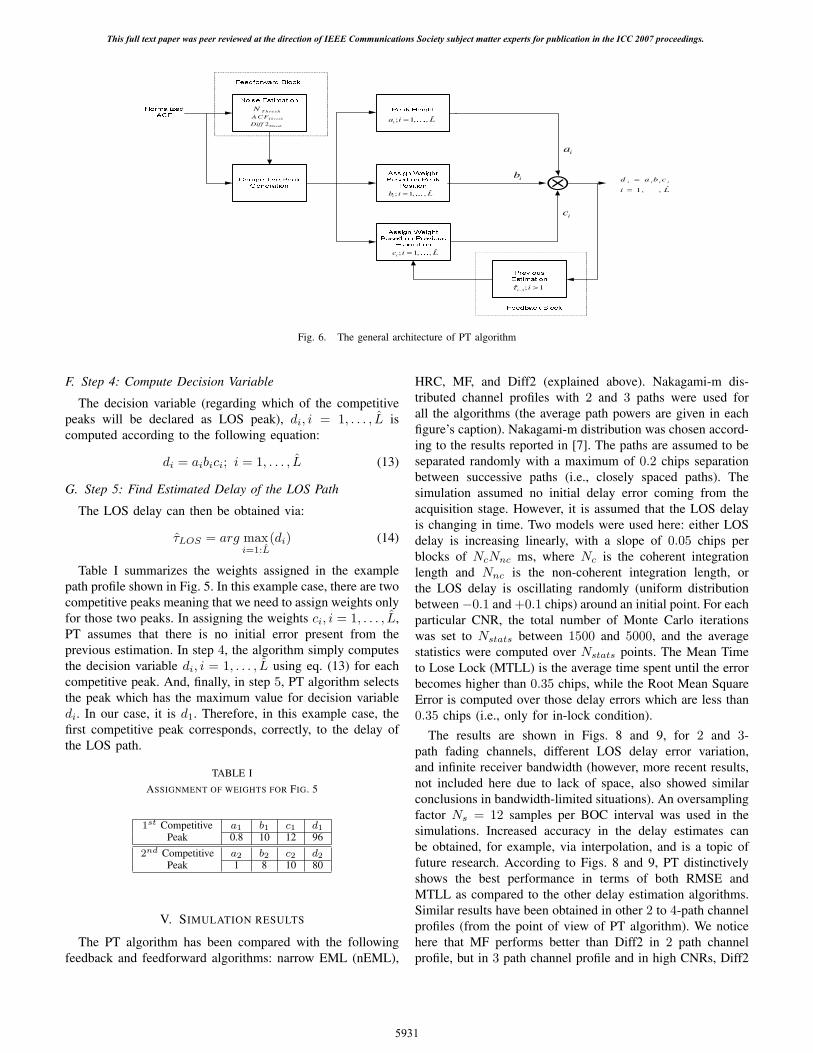
Noise Estimation
Competitive Peak
Generation
Peak Height
Assign Weight
Based on Peak
Position
Assign Weight
Based on Previous
Estimation
⊗
Previous
Estimation
Normalized
ACF
1ˆ ; 1i iτ − >
ˆ; 1, ,ia i L= …
ia
ˆ; 1, ,i i Lb = …
ib
ˆ; 1, ,ic i L= …
ic
Feedforward Block
Feedback Block
ˆ1, ,
i i i id a b c
i L
=
= …
T h re s hN
Th reshA C F
2ThreshDiff
Fig. 6. The general architecture of PT algorithm
F. Step 4: Compute Decision Variable
The decision variable (regarding which of the competitivepeaks will be declared as LOS peak), di, i = 1, . . . , L iscomputed according to the following equation:
di = aibici; i = 1, . . . , L (13)
G. Step 5: Find Estimated Delay of the LOS Path
The LOS delay can then be obtained via:
τLOS = arg maxi=1:L
(di) (14)
Table I summarizes the weights assigned in the examplepath profile shown in Fig. 5. In this example case, there are twocompetitive peaks meaning that we need to assign weights onlyfor those two peaks. In assigning the weights ci, i = 1, . . . , L,PT assumes that there is no initial error present from theprevious estimation. In step 4, the algorithm simply computesthe decision variable di, i = 1, . . . , L using eq. (13) for eachcompetitive peak. And, finally, in step 5, PT algorithm selectsthe peak which has the maximum value for decision variabledi. In our case, it is d1. Therefore, in this example case, thefirst competitive peak corresponds, correctly, to the delay ofthe LOS path.
TABLE I
ASSIGNMENT OF WEIGHTS FOR FIG. 5
1st Competitive a1 b1 c1 d1
Peak 0.8 10 12 96
2nd Competitive a2 b2 c2 d2
Peak 1 8 10 80
V. SIMULATION RESULTS
The PT algorithm has been compared with the followingfeedback and feedforward algorithms: narrow EML (nEML),
HRC, MF, and Diff2 (explained above). Nakagami-m dis-tributed channel profiles with 2 and 3 paths were used forall the algorithms (the average path powers are given in eachfigure’s caption). Nakagami-m distribution was chosen accord-ing to the results reported in [7]. The paths are assumed to beseparated randomly with a maximum of 0.2 chips separationbetween successive paths (i.e., closely spaced paths). Thesimulation assumed no initial delay error coming from theacquisition stage. However, it is assumed that the LOS delayis changing in time. Two models were used here: either LOSdelay is increasing linearly, with a slope of 0.05 chips perblocks of NcNnc ms, where Nc is the coherent integrationlength and Nnc is the non-coherent integration length, orthe LOS delay is oscillating randomly (uniform distributionbetween −0.1 and +0.1 chips) around an initial point. For eachparticular CNR, the total number of Monte Carlo iterationswas set to Nstats between 1500 and 5000, and the averagestatistics were computed over Nstats points. The Mean Timeto Lose Lock (MTLL) is the average time spent until the errorbecomes higher than 0.35 chips, while the Root Mean SquareError is computed over those delay errors which are less than0.35 chips (i.e., only for in-lock condition).
The results are shown in Figs. 8 and 9, for 2 and 3-path fading channels, different LOS delay error variation,and infinite receiver bandwidth (however, more recent results,not included here due to lack of space, also showed similarconclusions in bandwidth-limited situations). An oversamplingfactor Ns = 12 samples per BOC interval was used in thesimulations. Increased accuracy in the delay estimates canbe obtained, for example, via interpolation, and is a topic offuture research. According to Figs. 8 and 9, PT distinctivelyshows the best performance in terms of both RMSE andMTLL as compared to the other delay estimation algorithms.Similar results have been obtained in other 2 to 4-path channelprofiles (from the point of view of PT algorithm). We noticehere that MF performs better than Diff2 in 2 path channelprofile, but in 3 path channel profile and in high CNRs, Diff2
This full text paper was peer reviewed at the direction of IEEE Communications Society subject matter experts for publication in the ICC 2007 proceedings.
5931
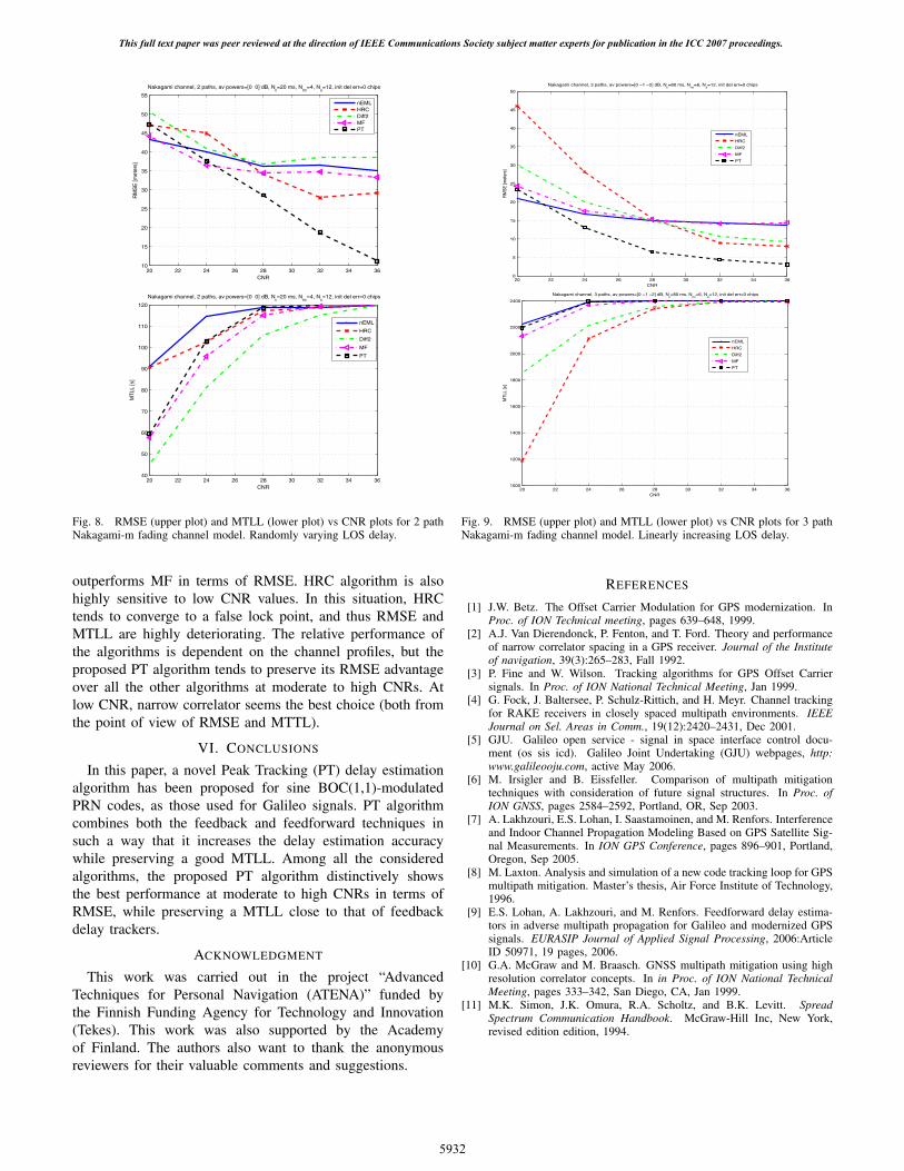
20 22 24 26 28 30 32 34 3610
15
20
25
30
35
40
45
50
55
CNR
RM
SE
[met
ers]
Nakagami channel, 2 paths, av powers=[0 0] dB, Nc=20 ms, N
nc=4, N
s=12, init del err=0 chips
nEMLHRCDiff2MFPT
20 22 24 26 28 30 32 34 3640
50
60
70
80
90
100
110
120
CNR
MT
LL [s
]
Nakagami channel, 2 paths, av powers=[0 0] dB, Nc=20 ms, N
nc=4, N
s=12, init del err=0 chips
nEML
HRC
Diff2
MF
PT
Fig. 8. RMSE (upper plot) and MTLL (lower plot) vs CNR plots for 2 pathNakagami-m fading channel model. Randomly varying LOS delay.
outperforms MF in terms of RMSE. HRC algorithm is alsohighly sensitive to low CNR values. In this situation, HRCtends to converge to a false lock point, and thus RMSE andMTLL are highly deteriorating. The relative performance ofthe algorithms is dependent on the channel profiles, but theproposed PT algorithm tends to preserve its RMSE advantageover all the other algorithms at moderate to high CNRs. Atlow CNR, narrow correlator seems the best choice (both fromthe point of view of RMSE and MTTL).
VI. CONCLUSIONS
In this paper, a novel Peak Tracking (PT) delay estimationalgorithm has been proposed for sine BOC(1,1)-modulatedPRN codes, as those used for Galileo signals. PT algorithmcombines both the feedback and feedforward techniques insuch a way that it increases the delay estimation accuracywhile preserving a good MTLL. Among all the consideredalgorithms, the proposed PT algorithm distinctively showsthe best performance at moderate to high CNRs in terms ofRMSE, while preserving a MTLL close to that of feedbackdelay trackers.
ACKNOWLEDGMENT
This work was carried out in the project “AdvancedTechniques for Personal Navigation (ATENA)” funded bythe Finnish Funding Agency for Technology and Innovation(Tekes). This work was also supported by the Academyof Finland. The authors also want to thank the anonymousreviewers for their valuable comments and suggestions.
20 22 24 26 28 30 32 34 360
5
10
15
20
25
30
35
40
45
50
CNR
RM
SE [m
eter
s]
Nakagami channel, 3 paths, av powers=[0 −1 −2] dB, Nc=80 ms, N
nc=6, N
s=12, init del err=0 chips
nEML
HRC
Diff2
MF
PT
20 22 24 26 28 30 32 34 361000
1200
1400
1600
1800
2000
2200
2400
CNR
MTL
L [s
]
Nakagami channel, 3 paths, av powers=[0 −1 −2] dB, Nc=80 ms, N
nc=6, N
s=12, init del err=0 chips
nEML
HRC
Diff2
MF
PT
Fig. 9. RMSE (upper plot) and MTLL (lower plot) vs CNR plots for 3 pathNakagami-m fading channel model. Linearly increasing LOS delay.
REFERENCES
[1] J.W. Betz. The Offset Carrier Modulation for GPS modernization. InProc. of ION Technical meeting, pages 639–648, 1999.
[2] A.J. Van Dierendonck, P. Fenton, and T. Ford. Theory and performanceof narrow correlator spacing in a GPS receiver. Journal of the Instituteof navigation, 39(3):265–283, Fall 1992.
[3] P. Fine and W. Wilson. Tracking algorithms for GPS Offset Carriersignals. In Proc. of ION National Technical Meeting, Jan 1999.
[4] G. Fock, J. Baltersee, P. Schulz-Rittich, and H. Meyr. Channel trackingfor RAKE receivers in closely spaced multipath environments. IEEEJournal on Sel. Areas in Comm., 19(12):2420–2431, Dec 2001.
[5] GJU. Galileo open service - signal in space interface control docu-ment (os sis icd). Galileo Joint Undertaking (GJU) webpages, http:www.galileooju.com, active May 2006.
[6] M. Irsigler and B. Eissfeller. Comparison of multipath mitigationtechniques with consideration of future signal structures. In Proc. ofION GNSS, pages 2584–2592, Portland, OR, Sep 2003.
[7] A. Lakhzouri, E.S. Lohan, I. Saastamoinen, and M. Renfors. Interferenceand Indoor Channel Propagation Modeling Based on GPS Satellite Sig-nal Measurements. In ION GPS Conference, pages 896–901, Portland,Oregon, Sep 2005.
[8] M. Laxton. Analysis and simulation of a new code tracking loop for GPSmultipath mitigation. Master’s thesis, Air Force Institute of Technology,1996.
[9] E.S. Lohan, A. Lakhzouri, and M. Renfors. Feedforward delay estima-tors in adverse multipath propagation for Galileo and modernized GPSsignals. EURASIP Journal of Applied Signal Processing, 2006:ArticleID 50971, 19 pages, 2006.
[10] G.A. McGraw and M. Braasch. GNSS multipath mitigation using highresolution correlator concepts. In in Proc. of ION National TechnicalMeeting, pages 333–342, San Diego, CA, Jan 1999.
[11] M.K. Simon, J.K. Omura, R.A. Scholtz, and B.K. Levitt. SpreadSpectrum Communication Handbook. McGraw-Hill Inc, New York,revised edition edition, 1994.
This full text paper was peer reviewed at the direction of IEEE Communications Society subject matter experts for publication in the ICC 2007 proceedings.
5932
Publication P2
M. Z. H. Bhuiyan, E. S. Lohan and M. Renfors, “Code Tracking Algorithms
for Mitigating Multipath Effects in Fading Channels for Satellite-based Posi-
tioning” in EURASIP Journal on Advances in Signal Processing, Vol. 2008,
Article ID 863629, 17 pages.
DOI= http://dx.doi.org/10.1155/2008/863629
Copyright c⃝2010 Mohammad Zahidul H. Bhuiyan et al. This is an open
access article distributed under the Creative Commons Attribution License,
which permits unrestricted use, distribution, and reproduction in any medium,
provided the original work is properly cited.


Hindawi Publishing CorporationEURASIP Journal on Advances in Signal ProcessingVolume 2008, Article ID 863629, 17 pagesdoi:10.1155/2008/863629
Research ArticleCode Tracking Algorithms for Mitigating Multipath Effects inFading Channels for Satellite-Based Positioning
Mohammad Zahidul H. Bhuiyan, Elena Simona Lohan, and Markku Renfors
Institute of Communications Engineering, Tampere University of Technology, P.O. Box 553, 33101 Tampere, Finland
Correspondence should be addressed to Elena Simona Lohan, [email protected]
Received 28 February 2007; Accepted 30 September 2007
Recommended by Richard J. Barton
The ever-increasing public interest in location and positioning services has originated a demand for higher performance globalnavigation satellite systems (GNSSs). In order to achieve this incremental performance, the estimation of line-of-sight (LOS)delay with high accuracy is a prerequisite for all GNSSs. The delay lock loops (DLLs) and their enhanced variants (i.e., feedbackcode tracking loops) are the structures of choice for the commercial GNSS receivers, but their performance in severe multipathscenarios is still rather limited. In addition, the new satellite positioning system proposals specify the use of a new modulation,the binary offset carrier (BOC) modulation, which triggers a new challenge in the code tracking stage. Therefore, in order to meetthis emerging challenge and to improve the accuracy of the delay estimation in severe multipath scenarios, this paper analyzesfeedback as well as feedforward code tracking algorithms and proposes the peak tracking (PT) methods, which are combinationsof both feedback and feedforward structures and utilize the inherent advantages of both structures. We propose and analyze heretwo variants of PT algorithm: PT with second-order differentiation (Diff2), and PT with Teager Kaiser (TK) operator, which willbe denoted herein as PT(Diff2) and PT(TK), respectively. In addition to the proposal of the PT methods, the authors propose alsoan improved early-late-slope (IELS) multipath elimination technique which is shown to provide very good mean-time-to-lose-lock (MTLL) performance. An implementation of a noncoherent multipath estimating delay locked loop (MEDLL) structure isalso presented. We also incorporate here an extensive review of the existing feedback and feedforward delay estimation algorithmsfor direct sequence code division multiple access (DS-CDMA) signals in satellite fading channels, by taking into account theimpact of binary phase shift keying (BPSK) as well as the newly proposed BOC modulation, more specifically, sine-BOC(1,1)(SinBOC(1,1)), selected for Galileo open service (OS) signal. The state-of-art algorithms are compared, via simulations, with theproposed algorithms. The main focus in the performance comparison of the algorithms is on the closely spaced multipath scenario,since this situation is the most challenging for estimating LOS component with high accuracy in positioning applications.
Copyright © 2008 Mohammad Zahidul H. Bhuiyan et al. This is an open access article distributed under the Creative CommonsAttribution License, which permits unrestricted use, distribution, and reproduction in any medium, provided the original work isproperly cited.
1. INTRODUCTION
Today, with the glorious advance in satellite navigation andpositioning technology, it is possible to pinpoint the exactlocation of any user anywhere on the surface of the globeat any time of day or night. Since its launch in the 1970s,the United States (US) Navstar global positioning system(GPS), has become the universal satellite navigation systemand reached full operational capability in 1990s [1]. This hascreated a monopoly, resulting in technical, political, strategicand economic dependence for millions of users [2]. In re-cent years, the rapid improvement and lowered price of com-puting power have allowed the integration of GPS chips into
small autonomous devices such as hand-held GPS receivers,personal digital assistants (PDAs), and cellular phones, in-creasing the speed of its consumption by the general pub-lic. In order to capitalize on this massive rising demand,and to cope with civil and military expectations in termsof performance, several projects were launched to give birthto a second generation of global navigation satellite systems(GNSSs) in the 1990s [3]. This led to two major GNSS de-cisions: the modernization of the current US GPS, knownas GPS II, and the independent European effort to create itsown GNSS, known as Galileo [4, 5]. These two systems arenow being finalized and are expected to be available to thepublic by the end of the decade. It is anticipated that once

2 EURASIP Journal on Advances in Signal Processing
the new European satellite navigation system Galileo is op-erational, the vast majority of all user receivers sold will beboth GPS and Galileo capable [2]. The benefits of receivingsignals from both constellations include improved accuracy,reliability, and availability [2].
Galileo signals, as well as GPS signals, are based on direct-sequence code division multiple access (DS-CDMA) tech-nique. Spread spectrum systems are known to offer fre-quency reuse, better multipath diversity, better narrowbandinterference rejection, and potentially, better capacity com-pared to narrowband techniques [6]. On the other hand,code and frequency synchronization are fundamental pre-requisites for the good performance of the receiver. Thesetwo tasks pose several problems in the presence of mobilewireless channels, due to the various adverse effects of thechannel, such as the multipath propagation, the possibilityof having the line-of-sight (LOS) component obstructed byclosely spaced nonline-of-sight (NLOS) components, or eventhe absence of LOS, and the high level of noise (especiallyin indoor scenarios). Moreover, the fading statistics of thechannel and the possible variations of the oscillator clocklimit the coherent integration time at the receiver (i.e., the re-ceiver filters which are used to smooth the various estimatesof channel parameters cannot have the bandwidth smallerthan the maximum Doppler spread of the channel withoutintroducing significant errors in the estimation process) [7–11]. The Doppler shift induced by the satellite is also proneto deteriorate the receiver performance, unless correctly es-timated and removed. Moreover, the fading behavior of thechannel paths induces a certain Doppler spread, directly re-lated to the terminal velocity. Typical GNSS receivers esti-mate jointly the code phase and the Doppler shifts or spreadsvia a two-dimensional search in time-frequency plane. Thedelay-Doppler estimation is usually done in two stages: ac-quisition (or coarse estimation), followed by tracking (orfine estimation). The acquisition and tracking stages will betreated here together, assuming implicitly that the frequency-time search space is reduced, for example, via some assistancedata (e.g., Doppler assistance, knowledge of previous delayestimates, etc.). In this situation, the delay estimation prob-lem can be seen as a tracking problem (i.e., very accurate de-lay estimates are desired) with initial code misalignment ofseveral chips or tens of chips and initial Doppler shift nothigher than few tens of Hertz.
One particular situation in multipath propagation is thesituation when LOS component is overlapping with one orseveral closely spaced NLOS components [7, 9–16] mak-ing the delay estimation process more difficult. This closelyspaced path scenario is most likely to be encountered in in-door positioning applications or in outdoor urban environ-ments, and is the main focus of our paper.
The main algorithms used for GPS and Galileo codetracking, providing a certain sufficiently small Doppler shift,are based on what is typically called a feedback delay esti-mator and are implemented based on a feedback loop. Themost known feedback delay estimators are the delay lockloops (DLLs) or early-minus-late (EML) loops [13, 17–21].The classical EML fails to cope with multipath propagation[6]. Therefore, several enhanced EML-based techniques have
been introduced in order to mitigate the effect of multipaths,especially in closely spaced path scenarios. One class of theseenhanced EML techniques is based on the idea of narrowingthe spacing between early and late correlators, that is, nar-row EML (nEML) [22–24]. Another class of enhanced EMLstructures uses a modified reference waveform for the corre-lation at the receiver, that narrows the main lobe of the cross-correlation function, at the expense of deterioration of signalpower. Examples belonging to this class are the high resolu-tion correlator (HRC) [24], the strobe correlators [23, 25],the pulse aperture correlator (PAC) [26] and the modifiedcorrelator reference waveform [23, 27]. One other similartracking structure is the multiple gate delay (MGD) corre-lator [28–30], where the number of early and late gates andthe weighting factors used to combine them in the discrimi-nator are parameters of the model. While coping better withthe ambiguities of BOC correlation function, MGD may havepoorer performance in multipaths than the narrow EML cor-relator and is very sensitive to the parameters chosen in thediscriminator function (i.e., weights and number of correla-tors) [31].
One more feedback code tracking structure is the early-late-slope (ELS) [32] correlator, also known as multipathelimination technique (MET), which is based on two corre-lator pairs at both sides of the correlation function’s centralpeak with parameterized spacing. Based on these two cor-relator pairs, the slopes of early and late sides of the cor-relation function can be computed and then, the intersec-tion point will be used for pseudorange correction. How-ever, simulation results performed in [23] showed that ELStechnique is outperformed by HRC from the point of viewof the multipath error envelopes (MEE), for both BPSK andSinBOC(n,n)-modulated signals. ELS is also outperformedby narrow correlator for very closely spaced paths (i.e., be-low 0.1 chip separation) and for paths spaced at about 1/2thof the envelope of the correlation function (i.e., 1 chip spac-ing for BPSK signals and 0.5 chip spacing for SinBOC(n,n)[23].
The feedback loops typically have a reduced ability todeal with closely spaced path scenarios under realistic as-sumptions (such as the presence of errors in the channel esti-mation process), a relatively slow convergence, and the possi-bility to lose the lock (i.e., they may start to estimate the LOSdelay with high estimation error) due to the feedback errorpropagation. Alternatively, various feedforward approacheshave been proposed in the literature and they have been sum-marized in [8]. While improving the delay estimation accu-racy, these approaches are sensitive to the noise-dependentthreshold choice.
One of the most promising feedforward code track-ing algorithms is the multipath estimating delay lock loop(MEDLL) [15, 33], implemented by NovAtel for GPS re-ceivers. The MEDLL is a method for mitigating the effectsdue to multipath within the receiver tracking loops. TheMEDLL does this by separating the incoming signal intoits LOS and multipath components. Using the LOS compo-nent, the unbiased measurements of code and carrier phasecan be made. Performance evaluation of narrow EML, wideEML (i.e., EML correlator with chip spacing of 1 chip) and

Mohammad Zahidul H. Bhuiyan et al. 3
MEDLL in terms of multipath mitigation capability is pre-sented in [34] for GPS C/A codes. The MEDLL shows bet-ter performance than narrow and wide EML DLLs, but itdoes not completely eliminate all multipath errors. Espe-cially multipath signals with small relative delays are diffi-cult to eliminate. However, the advantage of MEDLL is thatit reduces the influence of multipath signals by estimatingboth LOS and multipath parameters. However, the perfor-mance analysis of MEDLL has not been much studied forSinBOC(1,1) modulated signals. Moreover, classical MEDLLis based on a maximum-likelihood search, which is compu-tationally extensive. Here, we reduce the search space, by us-ing a noncoherent MEDLL approach and by incorporating aphase search unit, based on statistical distributions of mul-tipath phases. We will also include MEDLL in our perfor-mance comparison, as a benchmark algorithm.
Another feedforward technique is the slope differential(SD) approach, a recent multipath mitigation scheme basedon the slope difference of the prompt correlator output (thecorrelation is computed between the received signal and thelocally generated reference signal). This technique was firstproposed in [35]. Advantage of the SD scheme is that it doesnot require a high speed digital signal processing for the nar-row early-late spacing since it employs only the prompt cor-relator unlike standard DLLs [35]. In [35], it is assumed thatthe amplitude of the LOS signal is always larger than the am-plitude of the multipath signal, which is a rather limiting as-sumption from the point of view of realistic multipath prop-agation scenarios. Therefore, a slightly modified approach,named as second-order differentiation (Diff 2), is proposedin [31]. Unlike SD, Diff 2 computes an adaptive thresholdbased on the estimated noise variance of the channel ob-tained from the feedforward loop in order to estimate the de-lay of the first arriving path. Because of this adaptive thresh-old, Diff 2 is able to estimate the first path delay even in mul-tipath profiles where the first path power is less than or equalto the consecutive path powers [31].
The matched filter (MF) concept is another popular feed-forward technique which is extensively studied in [8, 36, 37].MF is based on a threshold computation which is determinedaccording to the channel condition provided by the feedfor-ward loop. At first, the noise level is estimated and then a lin-ear threshold is computed based on the noise variance plussome weight factor obtained from the feedforward loop. Thechoice of the weight factor is dependent on the modulationtype. For SinBOC(1,1)-modulated signals, it has to be cho-sen such that the side lobe peaks of the envelope of the cor-relation function (CF) between the received signal and lo-cally generated reference signal can be compensated. There-fore, the first peak of MF which is above the linear thresholdcorresponds to the estimated delay of the first path.
Another very promising code tracking algorithm isTeager-Kaiser (TK)-based delay estimation algorithm. Theprinciple and the properties of the TK-based delay estima-tion algorithm are described in detail in [38, 39]. TK ap-proach proved to give the best results for WCDMA scenar-ios in the presence of overlapping paths [9, 38]. According to[8], the performance of this algorithm is also very promis-ing in closely spaced multipath scenarios for LOS delay es-
timation of SinBOC(1,1)-modulated signal in terms of ac-curacy and complexity. However, the best results performedwith TK estimator were obtained with infinite receiver band-width. The presence of bandwidth limiting filter affects ad-versely the performance of TK estimator.
The purpose of our paper is two-fold: first, to proposean improved early-late-slope (IELS) technique, which in-creases the MTLL and decreases the RMSE compared withthe narrow correlator, and secondly, to introduce two peak-tracking-based techniques with optimized parameters, thatprovide the best LOS estimation accuracy among the otherstudied algorithms. Aditionally, the step-by-step implemen-tation of a noncoherent MEDLL with incorporated phase es-timation is given for both SinBOC and BPSK signals. In ourimproved ELS (IELS) technique, we propose two major up-dates to the basic ELS model. The first update is the adapta-tion of random spacing between the early and the late corre-lator pairs. This is mainly because of the fact that the randomspacing between the early and late correlator pairs will gen-erally provide more accuracy in order to draw slopes in theearly and late sides of the correlation function as compared tofixed spacing, especially when fading channel model is con-cerned. The second update is the utilization of the feedfor-ward information in order to determine the most appropri-ate peak on which the IELS technique should be applied. Thepeak tracking (PT) algorithms, as mentioned above, combinethe advantages of feedback and feedforward techniques, insuch a way that the delay estimation accuracy is increased,while still preserving a good mean time to lose lock (MTLL).We remark that the basic ideas of a peak tracking-like algo-rithm have been introduced by the authors in [40]. However,in [40], the PT was using only the second-order derivativeestimates and its parameters were chosen empirically. More-over, the algorithm presented in [40] is valid only for GalileoSinBOC(1,1)-modulated signals, while the work here is validfor both GPS and Galileo signals. We also explain here thechoice of all the PT parameters and we introduce also thePT-with-TK algorithm.
Simulation results in multipath fading channels are in-cluded, in order to compare the performance of the pro-posed algorithm with the performance of various feedbackand feedforward algorithms (some of them have been alreadymentioned in this introductory chapter, and the rest of them,which are less known or new, are explained in Sections 2 and3). The procedure of PT algorithm is detailed in Section 4.The last two sections are dedicated to the simulation resultsand conclusions.
2. SIGNAL AND CHANNEL MODEL
In what follows, the continuous-time model is adopted forclarity purpose. The signal s(t) transmitted from one satel-lite, with pseudorandom (PRN) code can be written as:
s(t) =√Ebpmod(t)⊗ c(t), (1)
where Eb is bit energy, pmod(t) is the modulation wave-form (e.g., BPSK for C/A GPS code or SinBOC(1,1) forL1 Galileo signals), and c(t) is the spread navigation data
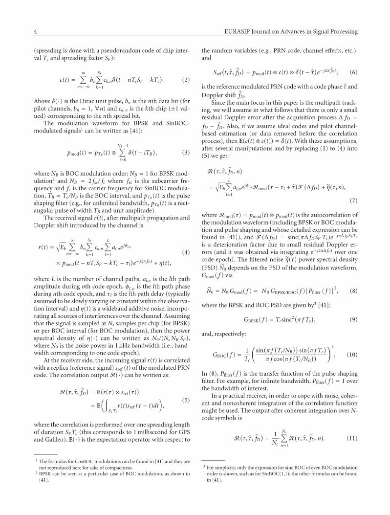
4 EURASIP Journal on Advances in Signal Processing
(spreading is done with a pseudorandom code of chip inter-val Tc and spreading factor SF):
c(t) =∞∑
n=−∞bn
SF∑
k=1
ck,nδ(t − nTcSF − kTc
). (2)
Above δ(·) is the Dirac unit pulse, bn is the nth data bit (forpilot channels, bn = 1, ∀n) and ck, n is the kth chip (±1 val-ued) corresponding to the nth spread bit.
The modulation waveform for BPSK and SinBOC-modulated signals1 can be written as [41]:
pmod(t) = pTB (t)⊗NB−1∑
i=0
δ(t − iTB
), (3)
where NB is BOC modulation order: NB = 1 for BPSK mod-ulation2 and NB = 2 fsc/ fc where fsc is the subcarrier fre-quency and fc is the carrier frequency for SinBOC modula-tion, TB = Tc/NB is the BOC interval, and pTB (t) is the pulseshaping filter (e.g., for unlimited bandwidth, pTB (t) is a rect-angular pulse of width TB and unit amplitude).
The received signal r(t), after multipath propagation andDoppler shift introduced by the channel is
r(t) =√Eb
∞∑n=−∞
bn
SF∑
k=1
ck,n
L∑
l=1
al,nejφl,n
× pmod(t − nTcSF − kTc − τl
)e− j2π fDt + η(t),
(4)
where L is the number of channel paths, al,n is the lth pathamplitude during nth code epoch, φl, n is the lth path phaseduring nth code epoch, and τl is the lth path delay (typicallyassumed to be slowly varying or constant within the observa-tion interval) and η(t) is a wideband additive noise, incorpo-rating all sources of interferences over the channel. Assumingthat the signal is sampled at Ns samples per chip (for BPSK)or per BOC interval (for BOC modulation), then the powerspectral density of η(·) can be written as N0/(Ns NB SF),where N0 is the noise power in 1 kHz bandwidth (i.e., band-width corresponding to one code epoch).
At the receiver side, the incoming signal r(t) is correlatedwith a replica (reference signal) sref (t) of the modulated PRNcode. The correlation output R(·) can be written as:
R(τ, τ, fD
) = E(r(τ)⊗ sref(τ)
)
= E(∫
SFTcr(t)sref (τ − t)dt
),
(5)
where the correlation is performed over one spreading lengthof duration SFTc (this corresponds to 1 millisecond for GPSand Galileo), E(·) is the expectation operator with respect to
1 The formulas for CosBOC modulations can be found in [41] and they arenot reproduced here for sake of compactness.
2 BPSK can be seen as a particular case of BOC modulation, as shown in[41].
the random variables (e.g., PRN code, channel effects, etc.),and
Sref(t, τ, fD
) = pmod(t)⊗ c(t)⊗ δ(t − τ)e− j2π fDt , (6)
is the reference modulated PRN code with a code phase τ and
Doppler shift fD.Since the main focus in this paper is the multipath track-
ing, we will assume in what follows that there is only a smallresidual Doppler error after the acquisition process Δ fD =fD − fD. Also, if we assume ideal codes and pilot channel-based estimation (or data removed before the correlationprocess), then E(c(t)⊗ c(t)) = δ(t). With these assumptions,after several manipulations and by replacing (1) to (4) into(5) we get:
R(τ, τ, fD,n
)
=√Eb
L∑
l=1
al,nejφl,nRmod
(τ − τl + τ
)F(Δ fD
)+ η(τ,n),
(7)
where Rmod(τ) = pmod(t)⊗ pmod(t) is the autocorrelation ofthe modulation waveform (including BPSK or BOC modula-tion and pulse shaping and whose detailed expression can befound in [41]), and F (Δ fD) = sinc(πΔ fDSF Tc)e− jπΔ fDSFTc
is a deterioration factor due to small residual Doppler er-rors (and it was obtained via integrating e− j2πΔ fDt over onecode epoch). The filtered noise η(τ) power spectral density(PSD) N0 depends on the PSD of the modulation waveform,Gmod( f ) via
N0 = N0 Gmod( f ) = N0 GBPSK/BOC( f )∣∣Pfilter ( f )
∣∣2, (8)
where the BPSK and BOC PSD are given by3 [41]:
GBPSK( f ) = Tcsinc2(π f Tc), (9)
and, respectively:
GBOC( f ) = 1Tc
(sin(π f(Tc/NB
))sin(π f Tc
)
π f cos(π f(Tc/NB
)))2
, (10)
In (8), Pfilter( f ) is the transfer function of the pulse shapingfilter. For example, for infinite bandwidth, Pfilter( f ) = 1 overthe bandwidth of interest.
In a practical receiver, in order to cope with noise, coher-ent and noncoherent integration of the correlation functionmight be used. The output after coherent integration over Nc
code symbols is
R(τ, τ, fD
) = 1Nc
Nc∑
n=1
R(τ, τ, fD,n
). (11)
3 For simplicity, only the expression for sine BOC of even BOC modulationorder is shown, such as for SinBOC(1,1); the other formulas can be foundin [41].

Mohammad Zahidul H. Bhuiyan et al. 5
The matched filter (MF) output after Nnc noncoherentintegration blocks become:
JMF
(τ, τ, fD
)= 1Nnc
∑
Nnc
R(τ, τ, fD
)R∗
(τ, τ, fD
). (12)
Under the assumption of zero-mean additive noise η(·), (12)becomes
JMF(τ, τ, fD
) ≈ Eb
L∑
l=1
L∑
l1=1
alal1ej(φl−φl1 )Rmod
(τ − Δτl1
)
×Rmod(τ − Δτ l1
)∣∣F (Δ fD)∣∣2
+∣∣η(τ)
∣∣2,
(13)
where al = E(al,n) and φl = E(φl,n) are the average amplitudeand phase values of path l over one code symbol interval,Δτ l = τl− τ, and η(τ) is the filtered and averaged noise (aftercoherent and noncoherent integration).
3. CODE TRACKING ALGORITHMS
3.1. Early late slope technique (ELS)
The early-late-slope (ELS) multipath mitigation techniquecan be easily explained by having a look at the signal’s au-tocorelation function (ACF) [32]. The general idea is to de-termine the slope at both sides of the ACF’s central peak.Once both slopes are known, they can be used to compute apseudorange correction that can be applied to the measuredpseudorange. This multipath mitigation technique has tem-porarily been used in some of NovAtel’s GPS receivers, whereit has been called multipath elimination technology (MET).
The principle of forming pseudorange corrections is il-lustrated in Figure 1. Here, R(τ) can be, for example, the co-herent correlation function of (11) or the noncoherent out-put JMF(τ, τ, fD) of (12). It can be noticed that the autocorre-lation peak is distorted due to the influence of the multipathsignal. The slope of the correlation function on the early sideof the peak is a1, and a2 is the slope of the late side of thepeak. The spacing between the early and late correlators is d.Using the slope information the following error function canbe derived to accurately estimate how much the correlatorsneed to be moved so that they are centered on the peak [32]:
T = y1 − y2 + (d/2)(a1 + a2)a1 − a2
, (14)
where T is the tracking error. This is actually the τ-coordinate of the intersection of the two straight lines (i.e.,the slopes a1 and a2). T will equal zero when the two cor-relators are positioned equidistant on each side of the peak.When T is non-zero it can be used to feed back to the hard-ware to keep the early and late correlators centered on thepeak.
3.2. Improved early late slope technique (IELS)
In our improved ELS (IELS) technique, there are two majorupdates to the basic ELS model. The first update is the adap-tation of random spacing between the early correlators (i.e.,
R(τ)
τ
K1 K2
K3K4
y1y2
y3y4
da1
a2
T
−τ3−τ1 τ2 τ4
Figure 1: Computation of a pseudorange correction T by analyzingthe slopes on both sides of the ACF
the spacing between E1 and E2) and also between the two latecorrelators (i.e., the spacing between L1 and L2). The rea-son is quite straightforward. The random spacing betweenthe correlators will generally be more appropriate than fixedspacing to draw correct slopes in both the early and late sidesof the correlation function, especially when fading channelmodel is concerned. The second update is the utilization ofthe feedforward information in order to determine the mostappropriate peak on which the IELS technique should be ap-plied. Unlike BPSK, BOC-modulated signal has side peakswith nonnegligible magnitudes. Therefore, there should be afair way to get rid of these side peaks not being considered asthe central peak. Similar with PT algorithm (that will be ex-plained in Section 3.4), an IELS threshold is computed basedon the estimated noise variance provided from the feedfor-ward structure. The chosen IELS peak is the one which isabove the threshold level as well as the closest to the previ-ous estimation.
3.3. Multipath estimating delay lock loop (MEDLL)implementation
Multipath estimating delay lock loop (MEDLL) is mainly de-signed to reduce both code and carrier multipath errors byestimating the parameters (i.e., amplitudes, delays, phases)of LOS plus multipath signals [15, 33]. The MEDLL of No-vAtel uses several correlators (e.g., 6 to 10) per channel inorder to determine accurately the shape of the multipath-corrupted correlation function. Then, a reference correlationfunction is used in a software module in order to determinethe best combination of LOS and NLOS components (i.e.,amplitudes, delays, phases and number of multipaths). Animportant aspect of the MEDLL is an accurate reference cor-relation function which could be constructed by averagingmeasured correlation functions over a significant amount oftotal averaging time [33].
The classical MEDLL approach involves the decompo-sition of correlation function into its direct and multipathcomponents. The MEDLL estimates the amplitude (al), delay

6 EURASIP Journal on Advances in Signal Processing
(τl) and phase (φl) of each multipath component using max-imum likelihood criteria. Each estimated multipath correla-tion function is in turn subtracted from the measured cor-relation function. After the completion of this process, onlythe estimate of the direct path correlation function is left. Fi-nally, a standard EML DLL is applied to the direct path com-ponent and an optimal estimate of the code tracking erroris obtained [34, 42]. There are several implementations pos-sible for MEDLL algorithm. Here, we chose a noncoherentMEDLL to make the implementation of the algorithm muchfaster and comparable with the complexity and the imple-mentation of the other discussed algorithms. The steps usedin our MEDLL implementation for BPSK and SinBOC(1,1)signals are summarized below.
(1) Find the maximum peak of R(τ) (where R(τ) =JMF(τ, τ, fD) from (12)) and its corresponding delay τ1, am-plitude a1 and phase φ1. However, we have to mention thatthe phase information is lost due to noncoherent integra-tion, thus we recover it by generating random (uniformlydistributed in [0 2π]) phases φl and by choosing that one cor-responding to the minimum mean square error of the resid-ual function R(k)(τ), k being the iteration index (see nextstep). In practice, Nrandom = 50 phases proved to give ac-curate enough results (with no so significant computationalburden).
(2) Subtract the contribution of the calculated peak, inorder to have a new approximation of the correlation func-
tion R(1)(τ) = R(τ) − |a1Rmod,ideal(t − τ1)e jφ1|2. HereRmod, ideal(·) is the reference correlation function for a BPSKor SinBOC-modulated signal, in the absence of multipath(which can be, e.g., computed only once, according to idealcodes [41], and stored at the receiver). We remark that thechoice of phase is not important during the first step (dueto the squared absolute value), and, thus the phase estima-tion can be ignored during the first step. Find out the newpeak of the residual function R(1) (·) and its correspondingdelay τ2, the amplitude a2 and phase φ2. Subtract the contri-bution of the first two peaks from R(τ) and find a new esti-mate of the first peak, as the peak of the residual R(2)(τ) =R(τ)− | a1Rmod,ideal(t − τ1)e jφ1 + a2Rmod,ideal(t − τ2)e jφ2|2.The reestimated values of the delay and amplitude of firstpeak are rewritten in τ1 and a1, respectively. For more thantwo peaks, once the two first peaks are found, the searchfor the lth peak is based on the residual R(l)(τ) = R(τ) −|∑ l−1
m=1amRmod,ideal(t − τm)e jφm|2, l ≥ 3. The procedure iscontinued iteratively until all desired peaks are estimated (seenext steps).
(3) The previous step is repeated until a certain criterionof convergence is met, that is, when residual function is be-low a threshold (e.g., set from 0.4 to 0.5 here) or until themoment when introducing a new delay does not improve theperformance (in the sense of root mean square error betweenthe original correlation function and the estimated correla-tion function).
Ignoring completely the phase information and keepingonly the amplitude estimates is also possible for MEDLL im-plementation, in order to decrease the computational bur-
den. However, slight deterioration of performance is no-ticed, as seen in the illustrative MEDLL examples of Figure 2(“Old MEDLL” method refers to the situation when thephase information is not taken into account, while the “NewMEDLL” method refers to the situation when the phaseinformation is searched for, in a random manner as ex-plained above, with Nrandom = 50). Here, Ns is the over-sampling factor (a chip interval has 40 samples in thisexample). By increasing the number of random pointsNrandom, the “New MEDLL” would approach the perfor-mance of coherent MEDLL.
3.4. Peak tracking algorithm
The motivation behind the development of the new PT al-gorithm was to find such an algorithm that fully utilizes theadvantages of both feedforward and feedback techniques andimproves the fine delay estimation. PT utilizes the adaptivethreshold obtained from the feedforward loop in order to de-termine some competitive delays, that is, the delays which arecompeting as being the actual delay (i.e., the delay of the firstarriving path). The adaptive threshold is based on the esti-mated noise variance of the absolute value of the correlationfunction between the received signal and the locally gener-ated reference signal. At the same time, PT explores the ad-vantage of feedback loop by calculating some weight factorsbased on the previous estimation in order to take decisionabout the actual delay. However, the utilization of feedbackloop is always a challenge since there is a chance to propagatethe delay error to subsequent estimations. Therefore, the de-lay error should remain in tolerable range (e.g., less than orequal to half of the width of main lobe of the envelope ofthe correlation function) so that the advantage from feed-back loop could be properly utilized.
For a SinBOC(1,1)-modulated signal, the width of mainlobe of the envelope of an ideal CF between the locally gener-ated reference signal and the received code is about 0.7 chipsas shown in Figure 3. Thus, when we deal with SinBOC(1,1)signals, we assume in what follows a maximum allowable de-lay error less than or equal to half of the width of the mainlobe (i.e., 0.7/2 = 0.35 chips). This means that, if the delayerror is higher (in absolute value) than 0.35 chips, the lockis considered to be lost and the acquisition and tracking pro-cesses should be restarted. For BPSK signals, the maximumdelay error will be 1 chip (since the width of the main lobe is2 chips).
The details of the PT algorithm are given in Section 4.Among the feedforward delay tracking algorithms, thematched filter (MF), the second-order differentiation(Diff 2), and the Teager-Kaiser (TK) algorithms are describedin the next subsections. Diff 2 and TK algorithms representalso parts of the building blocks of PT algorithm with Diff 2technique, denoted herein as PT(Diff 2) and of PT algorithmwith TK technique (PT(TK)).
3.5. MF peak and MF technique
In this context, the term MF peak is defined as any local max-imum point in the CF squared envelope that is greater than
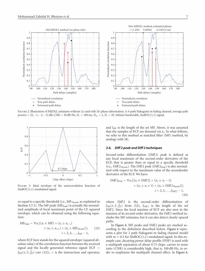
Mohammad Zahidul H. Bhuiyan et al. 7
18017016015014013012011010090
Path delays (samples)
0
0.1
0.2
0.3
0.4
0.5
0.6
0.7
0.8
0.9
1
Nor
mal
ized
corr
elat
ion
fun
ctio
n
Old MEDLL method (no phase info)
Normalized correlationTrue path delaysEstimated path delays
18017016015014013012011010090
Path delays (samples)
0
0.1
0.2
0.3
0.4
0.5
0.6
0.7
0.8
0.9
1
Nor
mal
ized
corr
elat
ion
fun
ctio
n
New MEDLL method, estimated phases= [1.4361 0.40926 −0.33013] rad
Normalized correlationTrue path delaysEstimated path delays
Figure 2: Illustration of MEDLL estimates without (a) and with (b) phase information. A 4-path Nakagami-m fading channel, average pathpowers = [0,−1,−2,−3] dB, CNR = 30 dB-Hz, Nc = 100 ms, Nnc = 2, Ns = 20. Infinite bandwidth, SinBOC(1,1) signal.
10.50−0.5−1
Chip offset (chips)
0
0.2
0.4
0.6
0.8
1
AC
F
0.7 chips
Figure 3: Ideal envelope of the autocorrelation function ofSinBOC(1,1)-modulated signal.
or equal to a specific threshold (i.e., MFThresh, as explained inSection 3.7.1). The MF peak (MFPeak) is actually the normal-ized amplitude of local maximum point of the CF squaredenvelope, which can be obtained using the following equa-tion:
MFPeak = ∀xi(xi ∈ MF)∧ (xi ≥ xi−1)
∧ (xi ≥ xi+1)∧ (xi ≥ MFThresh);i = 2, 3, . . . , lMF − 1,
(15)
where ECF here stands for the squared envelope (squared ab-solute value) of the correlation function between the receivedsignal and the locally generated reference signal: ECF =JMF(τ, τ, fD) (see (12)), ∧ is the intersection and operator,
and lMF is the length of the set MF. Above, it was assumedthat the samples of ECF are denoted via xi. In what follows,we refer to this method as matched filter (MF) method, byanalogy with [8].
3.6. Diff 2 peak and Diff 2 techniques
Second-order differentiation (Diff 2) peak is defined asany local maximum of the second-order derivative of theECF, that is greater than or equal to a specific threshold(i.e., Diff 2Thresh). The Diff 2 peak (Diff 2Peak) is also normal-ized with respect to the maximum value of the secondorderderivative of the ECF. We have:
Diff 2Peak = ∀xi(xi ∈ Diff 2
)∧ (xi ≥ xi − 1)
∧ (xi ≥ xi + 1)∧ (xi ≥ Diff 2Thresh
);
i = 2, 3, . . . , lDiff 2 − 1,(16)
where Diff 2 is the second-order differentiation ofJMF(τ, τ, fD) from (12), lDiff 2 is the length of the setDiff 2. Since the local maxima of ECF are also seen in themaxima of its second-order derivative, the Diff 2 method in-cludes the MF estimates, but it can also detect closely-spacedpaths.
In Figure 4, MF peaks and Diff 2 peaks are marked ac-cording to the definition described before. Figure 4 repre-sents a plot for 2 path Nakagami-m fading channel modelwith m = 0.5 for SinBOC(1,1)-modulated signal. In this ex-ample case, decaying power delay profile (PDP) is used witha multipath separation of about 0.75 chips. carrier to noiseratio (CNR) is considerably high, that is, 100 dB-Hz, in or-der to emphasize the multipath channel effect. In Figure 4,

8 EURASIP Journal on Advances in Signal Processing
3210−1−2−3
Delay error (chips)
0
0.1
0.2
0.3
0.4
0.5
0.6
0.7
0.8
0.9
1
Nor
mal
ized
non
-coh
eren
tC
F
2 path Nakagami-m fading channel model,multipath delay(s): [0 0.75122] chips, CNR: 100 dB-Hz
CFMF thresholdNoise threshold
MF peaks
(a)
3210−1−2−3
Delay error (chips)
−0.5
0
0.5
1
Nor
mal
ized
seco
nd-
orde
rdi
ffer
enti
atio
n(D
iff2)
2 path Nakagami-m fading channel model,multipath delay(s): [0 0.75122] chips, CNR: 100 dB-Hz
Diff2Diff2 thresholdNoise threshold
Diff2 peaks
(b)
Figure 4: MF Peaks (a) and Diff 2 Peaks (b) illustration. SinBOC(1,1) signal.
3210−1−2−3
Delay error (chips)
0
0.1
0.2
0.3
0.4
0.5
0.6
0.7
0.8
0.9
1
Nor
mal
ized
non
-coh
eren
tC
F
2 path Nakagami-m fading channel model,multipath delay(s): [0 0.75122] chips, CNR: 100 dB-Hz
Figure 5: Estimation of noise threshold for the same channel profileas in Figure 4.
the peaks marked in the two subplots correspond to thechannel delays and also to the MF and Diff 2 peaks (both MFand Diff 2 algorithms estimate correctly the channel paths inthis example).
3.7. Noise thresholds for MF and Diff 2 algorithms
Noise threshold (NThresh) is obtained based on the noise levelof the ECF. The noise level is estimated by taking the mean
of out-of-peak values of the ECF. The out-of-peak values areall the ECF points which fall outside the rectangular win-dow shown in Figure 5. The rectangular window is chosensuch that it contains all side lobe peaks of the ECF, due toBOC modulation, as well as multipath effects (we have to as-sume a maximum delay spread of the channel, but this choiceproved not to be so critical). Hence, the width of the rectan-gular window should not be less than 2 chips. In this examplecase, the width of the rectangular window was 2.4 chips.
3.7.1. MF threshold
MF Threshold (MFThresh) is basically computed from the esti-mated noise thresholdNThresh and a weight factorWMF usingthe following equation:
MFThresh = max
MFPeakWMF +NThresh, (17)
where MFPeak and NThresh were defined above and WMF isdefined as follows (the exact choice within these intervalsproved not to be critical):
0.1 ≤WMF ≤ 0.15 for BPSK,
0.3 ≤WMF ≤ 0.35 for SinBOC(1, 1),(18)
WMF was chosen optimized empirically (e.g., based on thelevels of the side lobes of ECF of SinBOC(1,1)-modulatedsignal). Figure 6 represents an ideal ECF for SinBOC(1,1)-modulated signal where the side lobe peak have approxima-tively the value 0.25. Therefore, WMF could be chosen ac-cording to (18) in order to avoid side lobe peaks being con-sidered as the competitive peaks. Definition of competitivepeaks is presented in Section 3–1.

Mohammad Zahidul H. Bhuiyan et al. 9
10.50−0.5−1
Chip offset (chips)
0
0.1
0.2
0.3
0.4
0.5
0.6
0.7
0.8
0.9
1
Non
-coh
eren
tA
CF
Figure 6: Ideal ECF (i.e., squared envelope of the correlation func-tion) of SinBOC(1,1)-modulated PRN Signal.
3.7.2. Diff 2 threshold
Diff 2 threshold (Diff 2Thresh) is computed from the estimatednoise threshold NThresh and a weight factor WD via:
Diff 2Thresh = max
Diff 2PeakWD +NThresh, (19)
where Diff 2Peak and NThresh were defined above and WD isdefined as follows (based on the second-order derivative val-ues of an ideal ECF):
0.22 ≤WD ≤ 0.3 for BPSK,
0.37 ≤WD ≤ 0.5 for SinBOC(1, 1).(20)
The second-order differentiation of ECF is very sensitiveto noise which emphasizes the fact that the weight factor WD
should be chosen higher than the weight factor WMF cho-sen for MFThresh. That is why the weight factor WD is slightlygreater than WMF .
3.8. Teager-kaiser (TK) peaks and TK technique
The nonlinear quadratic TK technique was first introducedfor measuring the real physical energy of a system [43]. Sinceits introduction, it has widely been used in various speechprocessing and image processing applications and, more re-cently, it has also been applied in code division multiple ac-cess (CDMA) applications [38, 39, 44]. It was found that thisnonlinear technique exhibits several attractive features suchas simplicity, efficiency and ability to track instantaneously-varying spatial modulation patterns [45]. Teager-Kaiser op-erator is chosen in the context of this paper because it provedto give the best results in delay estimation process when usedwith other CDMA type of signals, as explained in [38, 39, 44].Teager-Kaiser operator ΨTK(·) to a real or complex continu-ous signal x(t) is given by [39]:
ΨTK(x(t)) = x(t)x∗(t)− 12
[x (t)x∗(t) + x(t)x∗(t)
]. (21)
For discrete signals x(n), TK operator is defined as [39]:
ΨTK(x(n)) = x(n− 1)x∗(n− 1)
− 12
[x(n− 2)x∗(n) + x(n)x∗(n− 2)
].
(22)
TK peak is defined as any local maximum of the Teager-Kaiser operator applied to the ECF, that is greater than orequal to a specific threshold (i.e., TKThresh):
TKPeak = ∀xi(xi ∈ TK
)∧ (xi ≥ xi − 1)
∧ (xi ≥ xi+1)∧ (xi ≥ TKThresh
);
i = 2, 3, . . . , lTK − 1,
(23)
where TK = ΨTK(JMF(τ, τ, fD)) is the TK operator applied toECF and lTK is the length of the set TK.
Above, TK Threshold (TKThresh) is computed similarlywith MF and Diff 2 thresholds:
TKThresh = maxTKPeakWTK +NThresh, (24)
where WTK weight was obtained from the TK applied to anideal ECF and by optimization based on simulations, that is,
0.25 ≤WD ≤ 0.3 for BPSK,
0.3 ≤WD ≤ 0.32 for SinBOC (1, 1).(25)
3.9. Competitive peaks concept
The competitive peaks are to be used in the proposed peaktracking algorithms. A competitive peak (CPeak) can be ob-tained using the following equations:
CPeak = (MFPeak)∪ (Diff 2Peak), (26)
CPeak = (MFPeak)∪ (TKPeak), (27)
where the symbol ∪ is used as the union of two sets. Thismeans that we combine the delay estimates given by MF andDiff 2, or by MF and TK, and form a set of “competitive”delays, from which the final estimate will be selected.
Since, for GNSS applications, the point of interest is tofind the delay of the first arriving path (i.e., the LOS path),therefore, it would be enough to consider only the first fewcompetitive peaks (in their order of arrival). Hence, we as-sume that:
max (L) = 5. (28)
Figure 7 shows the competitive peaks for the same pathprofile as in Figures 4 and 5. The competitive peaks are ob-tained using (26). As it can be seen from Figure 7, for thisparticular example, there are in total two competitive peakswhich compete to be considered as being the actual delay ofthe LOS path.
In this example, the first competitive peak corresponds tothe delay of the first arriving path whereas the second com-petitive peak corresponds to the delay of the second arrivingpath which is approximately 0.75 chips apart from the firstpath.
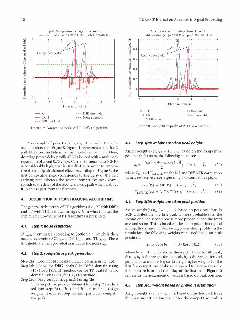
10 EURASIP Journal on Advances in Signal Processing
3210−1−2−3
Delay error (chips)
−0.5
0
0.5
1
Nor
mal
ized
non
-coh
eren
tC
F,n
orm
aliz
edD
iff2
2 path Nakagami-m fading channel model,multipath delay(s): [0 0.75122] chips, CNR: 100 dB-Hz
CFDiff2MF threshold
Diff2 thresholdNoise threshold
Competitive peaks
Figure 7: Competitive peaks of PT(Diff 2) algorithm.
An example of peak tracking algorithm with TK tech-nique is shown in Figure 8. Figure 4 represents a plot for 2path Nakagami-m fading channel model withm = 0.5. Here,decaying power delay profile (PDP) is used with a multipathseparation of about 0.75 chips. Carrier-to-noise ratio (CNR)is considerably high, that is, 100 dB-Hz, in order to empha-size the multipath channel effect. According to Figure 8, thefirst competitive peak corresponds to the delay of the firstarriving path whereas the second competitive peak corre-sponds to the delay of the second arriving path which is about0.75 chips apart from the first path.
4. DESCRIPTION OF PEAK TRACKING ALGORITHMS
The general architecture of PT algorithms (i.e., PT with Diff 2and PT with TK) is shown in Figure 9. In what follows, thestep by step procedure of PT algorithms is presented.
4.1. Step 1: noise estimation
NThresh is estimated according to Section 3.7, which is thenused to determine ACFThresh, Diff 2Thresh and TKThresh. Thesethresholds are then provided as input to the next step.
4.2. Step 2: competitive peak generation
Step 2(a): Look for MF peak(s) in ECF domain using (15).Step 2(b): Look for Diff 2 peak(s) in Diff 2 domain using
(16) (for PT(Diff 2) method) or for TK peak(s) in TKdomain using (23) (for PT(TK) method).
Step 2(c): Find competitive peak(s) using (26).The competitive peak(s) obtained from step 2 are thenfed into steps 3(a), 3(b) and 3(c) in order to assignweights in each substep for each particular competi-tive peak.
3210−1−2−3
Delay error (chips)
0
0.2
0.4
0.6
0.8
1
Nor
mal
ized
non
-coh
eren
tC
F,n
orm
aliz
edT
K
2 path Nakagami-m fading channel model,multipath delay(s): [0 0.75122] chips, CNR: 100 dB-Hz
CFTKMF threshold
TK thresholdNoise threshold
Competitive peaks
Figure 8: Competitive peaks of PT(TK) algorithm.
4.3. Step 3(a): weight based on peak height
Assign weight(s) (ai), i = 1, . . . , L, based on the competitivepeak height(s) using the following equation:
ai = [TMF(τi) + TDiff 2/TK(τi)]2
; i = 1, . . . , L, (29)
where TMF and TDiff 2/Tk are the MF and Diff 2/TK correlationvalues, respectively, corresponding to a competitive peak:
TMF(τi) = MF
(τi), i = 1, . . . , L, (30)
TDiff 2/TK(τi) = Diff 2/TK
(τi), i = 1, . . . , L. (31)
4.4. Step 3(b): weight based on peak position
Assign weight(s) bi, i = 1, . . . , L based on peak positions inECF distribution: the first peak is more probable than thesecond one, the second one is more probable than the thirdone and so on. This is based on the assumption that typicalmultipath channel has decreasing power-delay profile. In thesimulation, the following weights were used based on peakpositions:
[b1 b2 b3 b4 b5] = [1 0.8 0.6 0.4 0.2], (32)
where bi, i = 1, . . . , L denotes the weight factor for ith peak;that is, b1 is the weight for 1st peak, b2 is the weight for 2ndpeak, and, so on. It is logical to assign higher weights for thefirst few competitive peaks as compared to later peaks sincethe objective is to find the delay of the first path. Figure 10represents the assignment of weights based on peak position.
4.5. Step 3(c): weight based on previous estimation
Assign weight(s) ci, i = 1, . . . , L based on the feedback fromthe previous estimation: the closer the competitive peak is

Mohammad Zahidul H. Bhuiyan et al. 11
NormalizedACF
Feed-forward block
NoiseestimationNThresh
ACFThresh
Diff2Thresh
TKThresh
Competitivepeak
generation
Peak height
ai; i = 1, . . . , L
Assign weightbased on peak
position
bi; i = 1, . . . , L
Assign weightbased on previous
estimationci; i = 1, . . . , L Feed-back block
Previousestimationτi−1; i > 1
ai
bi
ci
di = ai∗bi + ci
i = 1, . . . , L
Figure 9: The general architecture of PT algorithms.
5th peak4th peak3rd peak2nd peak1st peak
Peak position, i
Wei
ght,b i
1
0.8
0.6
0.4
0.2
Figure 10: Weight assignment (bi, i = 1, . . . , L) based on peak po-sition
from the previous estimation, the higher the weight wouldbe for that particular competitive peak. Weight is assigned toeach competitive peak according to (33) as follows:
ci = 1− (τerr)i, i = 1, . . . , L, (33)
where (τerr)i is the delay error of the ith competitive peakwith respect to the previous estimation. For example, for adelay difference of 0.1 chips from the previous estimation,the weight factor ci would be 0.9, and for a delay differenceof 0.2 chips, the weight factor ci would be 0.8 and so on.
4.6. Step 4: compute the decision variable
The decision variable (regarding which of the competitivepeaks will be declared as LOS peak), di, i = 1, . . . , L is com-puted according to the following equation:
di = ai∗ bi + ci, i = 1, . . . , L, (34)
which means that the first two weights ai and bi have higherweight than the third weight. This decision variable was alsooptimized empirically, via simulations.
4.7. Step 5: find estimated delay of the LOS path
The LOS delay can then be obtained via:
τLOS = arg maxi=1:L
(di). (35)
Table 1 summarizes the weights assigned in the exam-ple path profile shown in Figure 7 for PT(Diff 2). Similar re-sults were obtained with PT(TK). In this example case, thereare two competitive peaks meaning that we need to assignweights only for those two peaks. In assigning weights forci, i = 1, . . . , L, PT assumes that there is no initial errorpresent from the previous estimation. In step 4, the algo-rithm simply computes the decision variable di, i = 1, . . . , Lusing (34) for each competitive peak. And, finally, in step 5,PT(Diff 2) algorithm selects the peak which has the maxi-mum value for the decision variable di. In our case, it is d1.Therefore, in this example, the first competitive peak corre-sponds to the true delay of the LOS path.
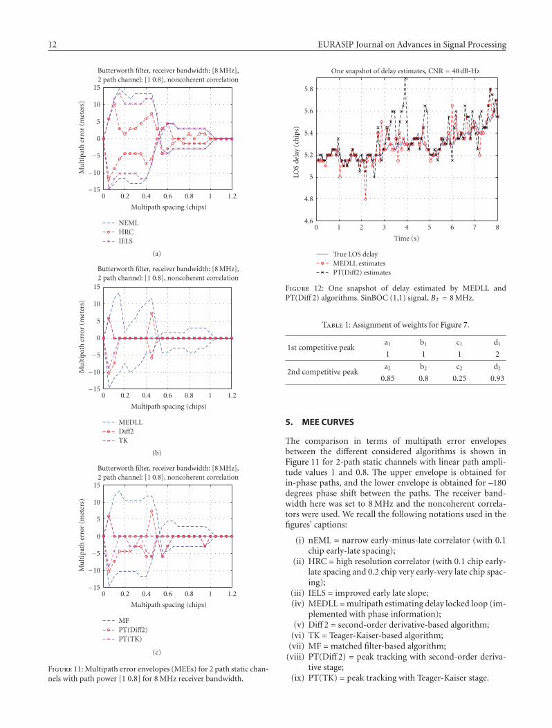
12 EURASIP Journal on Advances in Signal Processing
1.210.80.60.40.20
Multipath spacing (chips)
−15
−10
−5
0
5
10
15M
ult
ipat
her
ror
(met
ers)
Butterworth filter, receiver bandwidth: [8 MHz],2 path channel: [1 0.8], noncoherent correlation
NEMLHRCIELS
(a)
1.210.80.60.40.20
Multipath spacing (chips)
−15
−10
−5
0
5
10
15
Mu
ltip
ath
erro
r(m
eter
s)
Butterworth filter, receiver bandwidth: [8 MHz],2 path channel: [1 0.8], noncoherent correlation
MEDLLDiff2TK
(b)
1.210.80.60.40.20
Multipath spacing (chips)
−15
−10
−5
0
5
10
15
Mu
ltip
ath
erro
r(m
eter
s)
Butterworth filter, receiver bandwidth: [8 MHz],2 path channel: [1 0.8], noncoherent correlation
MFPT(Diff2)PT(TK)
(c)
Figure 11: Multipath error envelopes (MEEs) for 2 path static chan-nels with path power [1 0.8] for 8 MHz receiver bandwidth.
876543210
Time (s)
4.6
4.8
5
5.2
5.4
5.6
5.8
LOS
dela
y(c
hip
s)
One snapshot of delay estimates, CNR = 40 dB-Hz
True LOS delayMEDLL estimatesPT(Diff2) estimates
Figure 12: One snapshot of delay estimated by MEDLL andPT(Diff 2) algorithms. SinBOC (1,1) signal, BT = 8 MHz.
Table 1: Assignment of weights for Figure 7.
1st competitive peaka1 b1 c1 d1
1 1 1 2
2nd competitive peaka2 b2 c2 d2
0.85 0.8 0.25 0.93
5. MEE CURVES
The comparison in terms of multipath error envelopesbetween the different considered algorithms is shown inFigure 11 for 2-path static channels with linear path ampli-tude values 1 and 0.8. The upper envelope is obtained forin-phase paths, and the lower envelope is obtained for –180degrees phase shift between the paths. The receiver band-width here was set to 8 MHz and the noncoherent correla-tors were used. We recall the following notations used in thefigures’ captions:
(i) nEML = narrow early-minus-late correlator (with 0.1chip early-late spacing);
(ii) HRC = high resolution correlator (with 0.1 chip early-late spacing and 0.2 chip very early-very late chip spac-ing);
(iii) IELS = improved early late slope;(iv) MEDLL = multipath estimating delay locked loop (im-
plemented with phase information);(v) Diff 2 = second-order derivative-based algorithm;
(vi) TK = Teager-Kaiser-based algorithm;(vii) MF = matched filter-based algorithm;
(viii) PT(Diff 2) = peak tracking with second-order deriva-tive stage;
(ix) PT(TK) = peak tracking with Teager-Kaiser stage.
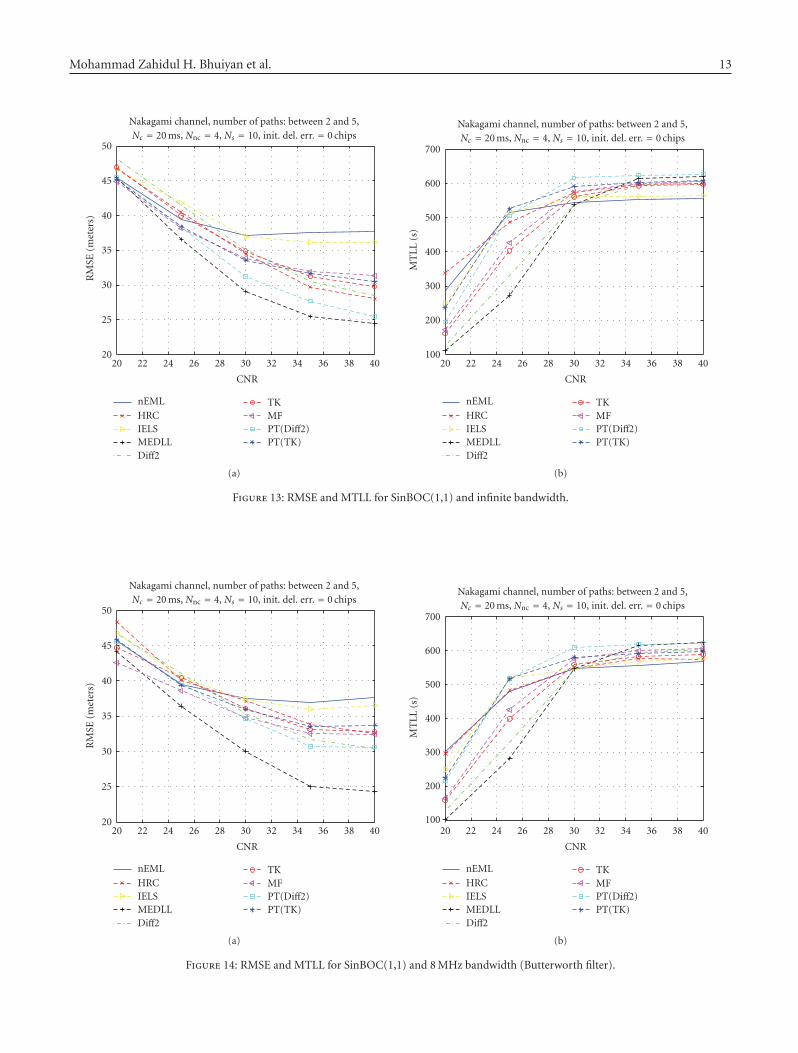
Mohammad Zahidul H. Bhuiyan et al. 13
4038363432302826242220
CNR
20
25
30
35
40
45
50
RM
SE(m
eter
s)
Nakagami channel, number of paths: between 2 and 5,Nc = 20 ms, Nnc = 4, Ns = 10, init. del. err. = 0 chips
nEML
HRCIELSMEDLLDiff2
TKMFPT(Diff2)PT(TK)
(a)
4038363432302826242220
CNR
100
200
300
400
500
600
700
MT
LL(s
)
Nakagami channel, number of paths: between 2 and 5,Nc = 20 ms, Nnc = 4, Ns = 10, init. del. err. = 0 chips
nEML
HRCIELSMEDLLDiff2
TKMFPT(Diff2)PT(TK)
(b)
Figure 13: RMSE and MTLL for SinBOC(1,1) and infinite bandwidth.
4038363432302826242220
CNR
20
25
30
35
40
45
50
RM
SE(m
eter
s)
Nakagami channel, number of paths: between 2 and 5,Nc = 20 ms, Nnc = 4, Ns = 10, init. del. err. = 0 chips
nEML
HRCIELSMEDLLDiff2
TKMFPT(Diff2)PT(TK)
(a)
4038363432302826242220
CNR
100
200
300
400
500
600
700
MT
LL
(s)
Nakagami channel, number of paths: between 2 and 5,Nc = 20 ms, Nnc = 4, Ns = 10, init. del. err. = 0 chips
nEML
HRCIELSMEDLLDiff2
TKMFPT(Diff2)PT(TK)
(b)
Figure 14: RMSE and MTLL for SinBOC(1,1) and 8 MHz bandwidth (Butterworth filter).

14 EURASIP Journal on Advances in Signal Processing
From Figure 11, the best MEE performance is obtainedwith the feedforward algorithms (TK, Diff 2, PT/TK, andPT/Diff 2), followed by MEDLL approaches. We also remarkthat IELS algorithm outperforms the narrow correlator forclosely spaced multipath (unlike the results reported in [23]).However, even after the improvements, ELS algorithm is out-performed by HRC method. However, MEEs are rather poorperformance criteria since they assume only static 2-pathchannels and do not take into account the channel changes.More robust performance estimators are those based on rootmean square error and mean-time-to-lose-lock values of thedelay estimates, as shown in Section 6.
6. SIMULATION RESULTS
Simulation results have been carried in Nakagami-m closelyspaced path scenarios for both SinBOC(1,1) and BPSK sig-nals, and for both limited and unlimited bandwidths. Theresults are described in the next two subsections.
6.1. SinBOC(1,1) case
Simulation results were carried for both infinite bandwidthsituation and for some severe bandwidth situation (i.e.,8 MHz double-sided bandwidth limitation). The received fil-ter for finite bandwidth case was a 8-MHz 5th order butter-worth filter with 0.1 dB passband ripples and 40 dB stopbandattenuation. The received signal was sampled atNs = 10 sam-ples per BOC interval, Ns being the oversampling factor (i.e.,here we have NBNs = 20 samples per chip). The channelpaths were assumed to have a Nakagami-m amplitude varia-tion (m = 0.5). The channel paths number was assumed tobe randomly varying between 2 and 5 paths (uniform distri-bution), and the successive path separation was also a ran-dom variable, distributed between 1/(NsNB) and 0.35 chips(i.e., closely spaced path scenarios). The channel paths wereassumed to obey a decaying power delay profile (PDP), withthe decaying factor μ = 0.2/NS/NBOC. 8000 random pointswere used in the computation of RMSE and MTLL values.The RMSE was computed only on those delay estimationvalues which were (in absolute value) less or equal to 0.35chips (i.e., half of the main lobe of the ECF). The MTLL wascomputed as the average number of delay estimates whoseerror (in absolute value) was less than 0.35 chips. The RMSEvalues are plotted in meters here, by using the relationshipRMSE[m] = RMSE[chips]cTc, where c is the speed of light. Itwas also assumed that the initial delay estimate coming fromthe acquisition stage is accurate to 0 chip delay error, but thatthe LOS delay is randomly varying in time (with a uniformdistribution of±0.05 chips around the previous delay). Thus,the purpose of the delay tracking unit is to keep the lock,that is, to follow these delay variations. A coherent integra-tion time of Nc = 20 ms was used, followed by noncoherentintegration on Nnc = 4 blocks.
A snapshot of estimated LOS delay versus the true LOSdelay for two of the considered algorithms is shown inFigure 12 for SinBOC(1,1) signal and 8 MHz receiver band-width.
876543210
Time (s)
6.6
6.8
7
7.2
7.4
7.6
7.8
8
LOS
dela
y(c
hip
s)
One snapshot of delay estimates, CNR = 40 dB-Hz
True LOS delayMEDLL estimatesPT(Diff2) estimates
Figure 15: One snapshot of delay estimated by MEDLL andPT(Diff 2) algorithms. BPSK signal, BT = 8 MHz.
Simulation results for SinBOC(1,1) case are shown inFigures 13 and 14, for infinite and finite bandwidth, respec-tively.
As seen in Figures 13 and 14, the best RMSE performancefor both SinBOC(1,1) is achieved by MEDLL and PT(Diff 2)approaches. However, MEDLL has quite poor MTLL perfor-mance (it tends to lose lock faster), thus the best tradeoff be-tween RMSE and MTLL is achieved, by PT(Diff 2) and HRCalgorithms. PT(TK) has poorer performance than PT(Diff 2)algorithm.
6.2. BPSK case
For BPSK signals, similar parameters as for SinBOC(1,1) sig-nal were used in the simulations. The only differences were ahigher oversampling factor Ns = 16, for an increased accu-racy (since the number of samples per chip is Ns for BPSKcase, while, for SinBOC(1,1), it was 2Ns) and the succes-sive path spacing of 1 chip (since the width of the ECF is 2chips for BPSK). Also, the RMSE values are computed overthe delay estimates which are at most half of the main lobewidth apart from the true LOS estimate, which correspondsto 1 chip for BPSK case. The statistics were also done forNrand = 8000 random realizations (each random realizationhas a length of NcNnc milliseconds), thus the best MTLL thatcan be achieved by our simulations is NrandNcNnc (here, thiscorresponds to 640 s).
A snapshot of estimated LOS delay versus the true LOSdelay for two of the considered algorithms is shown inFigure 15 for BPSK signal and 8 MHz receiver bandwidth.RMSE and MTLL values for BPSK case are shown in Figures16 and 17, for infinite and finite bandwidth case, respectively.
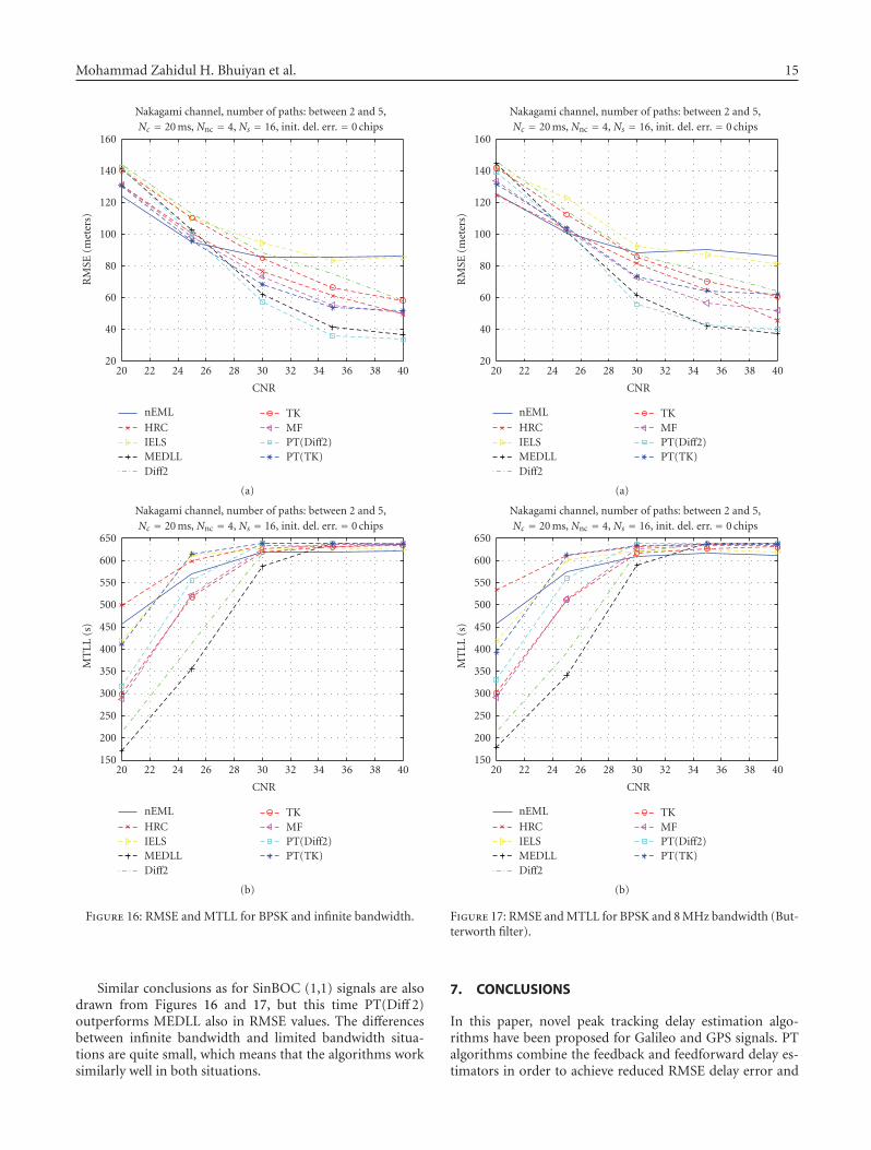
Mohammad Zahidul H. Bhuiyan et al. 15
4038363432302826242220
CNR
20
40
60
80
100
120
140
160
RM
SE(m
eter
s)
Nakagami channel, number of paths: between 2 and 5,Nc = 20 ms, Nnc = 4, Ns = 16, init. del. err. = 0 chips
nEML
HRCIELSMEDLLDiff2
TKMFPT(Diff2)PT(TK)
(a)
4038363432302826242220
CNR
150
200
250
300
350
400
450
500
550
600
650
MT
LL(s
)
Nakagami channel, number of paths: between 2 and 5,Nc = 20 ms, Nnc = 4, Ns = 16, init. del. err. = 0 chips
nEML
HRCIELSMEDLLDiff2
TKMFPT(Diff2)PT(TK)
(b)
Figure 16: RMSE and MTLL for BPSK and infinite bandwidth.
Similar conclusions as for SinBOC (1,1) signals are alsodrawn from Figures 16 and 17, but this time PT(Diff 2)outperforms MEDLL also in RMSE values. The differencesbetween infinite bandwidth and limited bandwidth situa-tions are quite small, which means that the algorithms worksimilarly well in both situations.
4038363432302826242220
CNR
20
40
60
80
100
120
140
160
RM
SE(m
eter
s)
Nakagami channel, number of paths: between 2 and 5,Nc = 20 ms, Nnc = 4, Ns = 16, init. del. err. = 0 chips
nEML
HRCIELSMEDLLDiff2
TKMFPT(Diff2)PT(TK)
(a)
4038363432302826242220
CNR
150
200
250
300
350
400
450
500
550
600
650
MT
LL(s
)
Nakagami channel, number of paths: between 2 and 5,Nc = 20 ms, Nnc = 4, Ns = 16, init. del. err. = 0 chips
nEML
HRCIELSMEDLLDiff2
TKMFPT(Diff2)PT(TK)
(b)
Figure 17: RMSE and MTLL for BPSK and 8 MHz bandwidth (But-terworth filter).
7. CONCLUSIONS
In this paper, novel peak tracking delay estimation algo-rithms have been proposed for Galileo and GPS signals. PTalgorithms combine the feedback and feedforward delay es-timators in order to achieve reduced RMSE delay error and

16 EURASIP Journal on Advances in Signal Processing
promising mean time to lose lock. Among all the consid-ered algorithms, the best tradeoff between RMSE and MTLLwas achieved via PT(Diff 2) algorithm, which decreased con-siderably the delay estimation error at moderate to highCNRs, while still preserving a better MTLL compared withother feedforward tracking approaches. We also presented animproved early-late-slope technique which outperforms thenarrow correlator especially in the presence of short delaymultipath, where the classical ELS was showing worse results.We have as well presented a reduced complexity implementa-tion of a noncoherent MEDLL, where the phase informationwas searched for via statistical assumptions. Extensive sim-ulation results in both limited and unlimited receiver band-width have been presented, including 9 feedback and feed-forward delay tracking algorithms. We have also shown thatat small CNRs (e.g., up to 25 dB-Hz for a coherent integra-tion time of 20 milliseconds), narrow correlator is still thebest choice among the considered algorithms. However, itsperformance is still far from accurate. Better results can beachieved via increasing CNRs (or, alternatively) increasingNc, with a combined feedback-feedforward approach.
ACKNOWLEDGMENTS
This work was carried out in the project “Advanced Tech-niques for Personal Navigation (ATENA)” funded by theFinnish Funding Agency for Technology and Innovation(Tekes). This work has also been partially supported by theAcademy of Finland.
REFERENCES
[1] E. D. Kaplan, Understanding Gps: Principles and Applications,Artech House, Boston, Mass, USA, 1996.
[2] E. Chatre, J. Swann, and D. Ludwig, “Galileo: benefits for lo-cation based services,” Journal of Global Positioning Systems,vol. 2, no. 1, pp. 57–66, 2003.
[3] K. L. Kovach and K. L. Van Dyke, “GPS in ten years,” in Pro-ceedings of the 10th International Technical Meeting of the Satel-lite Division of the Institute of Navigation (ION-GPS ’97), vol. 2,pp. 1251–1259, Kansas City, Mo, USA, September 1997.
[4] G. W. Hein, J. Godet, J. L. Issler, J. C. Martin, T. Pratt, andR. Lucas, “Status of Galileo frequency and signal design,” inCDROM Proceedings of the International Technical Meeting ofthe Institute of Navigation (ION-GPS ’02), Portland, Ore, USA,September 2002.
[5] G. W. Hein, M. Irsigler, J. A. A. Rodriguez, and T. Pany, “Per-formance of Galileo L1 signal candidates,” in Proceedings of theEuropean Navigation Conference (ENC-GNSS ’04), Rotterdam,The Netherlands, May 2004.
[6] M. K. Simon, J. K. Omura, R. A. Scholtz, and B. K. Levitt,Spread Spectrum Communication Handbook, McGraw-Hill,New York, NY, USA, 1994.
[7] E. R. Jativa and J. Vidal, “First arrival detection for position-ing in mobile channels,” in Proceedings of the 13th IEEE In-ternational Symposium on Personal, Indoor and Mobile RadioCommunications (PIMRC ’02), vol. 4, pp. 1540–1544, Lisbon,Portugal, September 2002.
[8] A. Lakhzouri, E. S. Lohan, R. Hamila, and M. Rentors, “Ex-tended Kalman filter channel estimation for line-of-sight de-tection in WCDMA mobile positioning,” EURASIP Journal on
Applied Signal Processing, vol. 2003, no. 13, pp. 1268–1278,2003.
[9] E. S. Lohan, Multipath delay estimators for fading channels withapplications in CDMA receivers and mobile positioning, Ph.D.thesis, Tampere University of Technology, Tampere, Finland,October 2003.
[10] J. Vidal, M. Najar, and R. Jativa, “High resolution time-of-arrival detection for wireless positioning systems,” in Pro-ceedings of the 56th IEEE Vehicular Technology Conference(VTC ’02), vol. 4, pp. 2283–2287, Vancouver, BC, Canada,September 2002.
[11] N. R. Yousef and A. H. Sayed, “Detection of fading overlap-ping multipath components for mobile-positioning systems,”IEEE International Conference on Communications, vol. 10, pp.3102–3106, 2001.
[12] D. D. Colclough and E. L. Titlebaum, “Delay-doppler POCSfor specular multipath,” in Proceedings of IEEE Interna-tional Conference on Acoustics, Speech and Signal Processing(ICASSP ’02), vol. 4, pp. 3940–3943, 2002.
[13] G. Fock, J. Baltersee, P. Schulz-Rittich, and H. Meyr, “Channeltracking for rake receivers in closely spaced multipath envi-ronments,” IEEE Journal on Selected Areas in Communications,vol. 19, no. 12, pp. 2420–2431, 2001.
[14] Z. Kostic and G. Pavlovic, “Resolving subchip-spaced multi-path components in CDMA communication systems,” IEEETransactions on Vehicular Technology, vol. 48, no. 6, pp. 1803–1808, 1999.
[15] R. D. J. van Nee, “The multipath estimating delay lock loop,” inProceedings of the 2nd IEEE International Symposium on SpreadSpectrum Techniques and Applications (ISSTA ’92), pp. 39–42,Yokohama, Japan, November-December 1992.
[16] N. R. Yousef and A. H. Sayed, “A new adaptive estimation al-gorithm for wireless location findingsystems,” in Proceedingsof the 33rd Asilomar Conference on Signals, Systems, and Com-puters (ACSSC ’99), vol. 1, pp. 491–495, Pacific Grove, Calif,USA, October 1999.
[17] P. Fine and W. Wilson, “Tracking algorithms for GPS offsetcarrier signals,” in Proceedings of the National Technical Meet-ing of the Institute of Navigation (ION-NTM ’99), San Diego,Calif, USA, January 1999.
[18] J. Baltersee, G. Fock, and P. Schulz-Rittich, “Adaptive code-tracking receiver for direct-sequence code division multipleaccess (CDMA) communications over multipath fading chan-nels and method for signal processing in a Rake receiver,” USPatent Application Publication, US 2001/0014114 A1 (LucentTechnologies), August 2001.
[19] R. Bischoff, R. Hab-Umbach, W. Schulz, and G. Heinrichs,“Employment of a multipath receiver structure in a combinedGALILEO/UMTS receiver,” in Proceedings of the 55th IEEEVehicular Technology Conference (VTC ’02), vol. 4, pp. 1844–1848, Birmingham, Ala, USA, May 2002.
[20] K.-C. Chen and L. D. Davisson, “Analysis of SCCL as a PN-code tracking loop,” IEEE Transactions on Communications,vol. 42, no. 11, pp. 2942–2946, 1994.
[21] M. Laxton, “Analysis and simulation of a new code trackingloop for GPS multipath mitigation,” M.S. thesis, Air Force In-stitute of Technology, Dayton, Ohio, USA, 1996.
[22] A. J. Van Dierendonck, P. Fenton, and T. J. Ford, “Theory andperformance of narrow correlator spacing in a GPS receiver,”Journal of the Institute of Navigation, vol. 39, no. 3, pp. 265–283, 1992.
[23] M. Irsigler and B. Eissfeller, “Comparison of multipath mit-igation techniques with consideration of future signal struc-tures,” in Proceedings of the International Technical Meeting of
Mohammad Zahidul H. Bhuiyan et al. 17
the Institute of Navigation (ION-GPS/GNSS ’03), pp. 2584–2592, Portland, Ore, USA, September 2003.
[24] A. McGraw and M. Braasch, “GNSS multipath mitigation us-ing high resolution correlator concepts,” in Proceedings of theNational Technical Meeting of the Institute of Navigation (ION-NTM ’99), pp. 333–342, San Diego, Calif, USA, January 1999.
[25] L. Garin and J.-M. Rousseau, “Enhanced strobe correlatormultipath rejection for code and carrier,” in Proceedings of the10th International Technical Meeting of the Satellite Division ofthe Institute of Navigation (ION-GPS ’97), vol. 1, pp. 559–568,Kansas City, Mo, USA, September 1997.
[26] J. Jones, P. Fenton, and B. Smith, “Theory and performance ofthe pulse aperture correlator,” Tech. Rep., NovAtel, Calgary,Alberta, Canada, Septemper 2004, http://www.novatel.com/Documents/Papers/PAC.pdf.
[27] L. R. Weill, “Multipath mitigation—how good can it get withnew signals?” GPS World, vol. 16, no. 6, pp. 106–113, 2003.
[28] R. Fante, “Unambiguous tracker for GPS binary-offset car-rier signals,” in Proceedings of the 59th ION National TechnicalMeeting, pp. 141–145, Albuquerque, NM, USA, June 2003.
[29] R. Fante, “Unambiguous first-order tracking loop M-Code,”Tech. Rep. MTR 94B0000040, MITRE, Bedford, Mass, USA,July 2004.
[30] P. A. Bello and R. L. Fante, “Code tracking performance fornovel unambiguous M-Code time discriminators,” in Proceed-ings of the National Technical Meeting of the Institute of Navi-gation (ION-NTM ’05), pp. 293–298, San Diego, Calif, USA,January 2005.
[31] M. Z. H. Bhuiyan, “Analyzing code tracking algorithms forgalileo open service signal,” M.S. thesis, Tampere Universityof Technology, Tampere, Finland, 2006.
[32] B. R. Townsend and P. Fenton, “A practical approach to the re-duction of pseudorange multipath errors in a L1 GPS receiver,”in Proceedings of the 7th International Technical Meeting of theSatellite Division of the Institute of Navigation (ION-GPS ’94),vol. 1, pp. 143–148, Salt Lake City, Uyah, USA, September1994.
[33] R. D. J. van Nee, J. Siereveld, P. Fenton, and B. R. Townsend,“Multipath estimating delay lock loop: approaching theoret-ical accuracy limits,” in Proceedings of IEEE Position Locationand Navigation Symposium (PLANS ’94), pp. 246–251, Las Ve-gas, Nev, USA, April 1994.
[34] B. R. Townsend, R. D. J. van Nee, P. Fenton, and A. J. VanDierendonck, “Performance evaluation of the multipath es-timating delay lock loop,” in Proceedings of the Annual Na-tional Technical Meeting of the Institute of Navigation (ION-NTM ’95), pp. 277–283, Anaheim, Calif, USA, January 1995.
[35] C. Lee, S. Yoo, S. Yoon, and S. Y. Kim, “A novel multipath mit-igation scheme based on slope differential of correlator out-put for Galileo systems,” in Proceedings of the 8th InternationalConference Advanced Communication Technology (ICACT ’06),vol. 2, pp. 1360–1363, Phoenix Park, Korea, February 2006.
[36] J. Joutsensalo, “Algorithms for delay estimation and track-ing in CDMA,” in Proceedings of the IEEE International Con-ference on Communications Montreal Towards the KnowledgeMillennium (ICC ’97), vol. 1, pp. 366–370, Montreal, Quebec,Canada, June 1997.
[37] J. Iinatti, Matched filter code acquisition employing a medianfilter in direct sequence spread-spectrum systems with jamming,Ph.D. thesis, University of Oulu, Oulu, Finland, 1997.
[38] E. S. Lohan, R. Hamila, A. Lakhzouri, and M. Renfors, “Highlyefficient techniques for mitigating the effects of multipath
propagation in DS-CDMA delay estimation,” IEEE Transac-tions on Wireless Communications, vol. 4, no. 1, pp. 149–162,2005.
[39] R. Hamila, E. S. Lohan, and M. Renfors, “Subchip multi-path delay estimation for downlink WCDMA system based onTeager-Kaiser operator,” IEEE Communications Letters, vol. 7,no. 1, pp. 1–3, 2003.
[40] M. Z. H. Bhuiyan, E. S. Lohan, and M. Renfors, “Peak track-ing algorithm for Galileo-based positioning in multipath fad-ing channels,” in Proceedings of IEEE International Conferenceon Communications (ICC ’07), pp. 5927–5932, Glasgow, Scot-land, UK, June 2007.
[41] E. S. Lohan, A. Lakhzouri, and M. Renfors, “Binary-offset-carrier modulation techniques with applications in satel-lite navigation systems,” Wireless Communications and MobileComputing, vol. 7, no. 6, pp. 767–779, 2007.
[42] B. R. Townsend, P. Fenton, A. J. van Dierendonck, and R. D.J. van Nee, “L1 carrier phase multipath error reduction us-ing MEDLL technology,” in Proceedings of the 8th InternationalTechnical Meeting of the Satellite Division of the Institute of Nav-igation (ION-GPS ’95), vol. 2, pp. 1539–1544, 1995.
[43] J. F. Kaiser, “On a simple algorithm to calculate the ‘energy’of a signal,” in Proceedings of IEEE International Conference onAcoustics, Speech and Signal Processing (ICASSP ’90), vol. 1, pp.381–384, Albuquerque, NM, USA, April 1990.
[44] R. Hamila, E. S. Lohan, and M. Renfors, “Novel technique formultipath delay estimation in GPS receivers,” in Proceedings ofInternational Conference on Third Generation Wireless and Be-yond (3GWireless ’01), pp. 993–998, San Francisco, Calif, USA,June 2001.
[45] R. Hamila, Synchronization and multipath delay estimation al-gorithms for digital receivers, Ph.D. thesis, Tampere Universityof Technology, Tampere, Finland, June 2002.

Publication P3
M. Z. H. Bhuiyan, X. Hu, E. S. Lohan and M. Renfors, “Multipath mitigation
performance of multi-correlator based code tracking algorithms in closed and
open loop model” in Proc. of The 15th European Wireless Conference, pp.:
84 - 89, 17 - 20 May 2009, Aalborg, Denmark.
Copyright c⃝2009 IEEE. Reprinted with permission.
kulkki
Text Box
This material is posted here with permission of the IEEE. Such permission of the IEEE does not in any way imply IEEE endorsement of any of the Tampere University of Technology's products or services. Internal or personal use of this material is permitted. However, permission to reprint/republish this material for advertising or promotional purposes or for creating new collective works for resale or redistribution must be obtained from the IEEE by writing to [email protected]. By choosing to view this material, you agree to all provisions of the copyright laws protecting it.

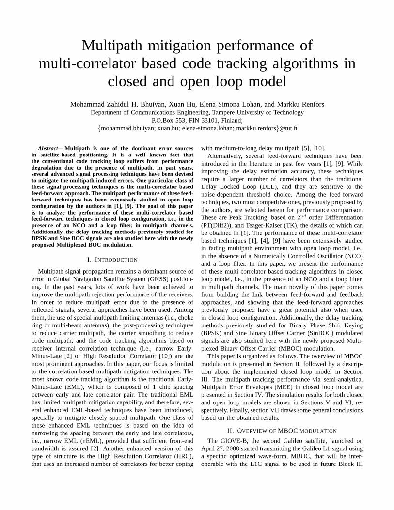
Multipath mitigation performance ofmulti-correlator based code tracking algorithms in
closed and open loop modelMohammad Zahidul H. Bhuiyan, Xuan Hu, Elena Simona Lohan, and Markku Renfors
Department of Communications Engineering, Tampere University of TechnologyP.O.Box 553, FIN-33101, Finland;
mohammad.bhuiyan; xuan.hu; elena-simona.lohan; [email protected]
Abstract— Multipath is one of the dominant error sourcesin satellite-based positioning. It is a well known fact thatthe conventional code tracking loop suffers from performancedegradation due to the presence of multipath. In past years,several advanced signal processing techniques have been devisedto mitigate the multipath induced errors. One particular class ofthese signal processing techniques is the multi-correlator basedfeed-forward approach. The multipath performance of thesefeed-forward techniques has been extensively studied in open loopconfiguration by the authors in [1], [9]. The goal of this paperis to analyze the performance of these multi-correlator basedfeed-forward techniques in closed loop configuration, i.e., in thepresence of an NCO and a loop filter, in multipath channels.Additionally, the delay tracking methods previously studied forBPSK and Sine BOC signals are also studied here with the newlyproposed Multiplexed BOC modulation.
I. I NTRODUCTION
Multipath signal propagation remains a dominant source oferror in Global Navigation Satellite System (GNSS) position-ing. In the past years, lots of work have been achieved toimprove the multipath rejection performance of the receivers.In order to reduce multipath error due to the presence ofreflected signals, several approaches have been used. Amongthem, the use of special multipath limiting antennas (i.e.,chokering or multi-beam antennas), the post-processing techniquesto reduce carrier multipath, the carrier smoothing to reducecode multipath, and the code tracking algorithms based onreceiver internal correlation technique (i.e., narrow Early-Minus-Late [2] or High Resolution Correlator [10]) are themost prominent approaches. In this paper, our focus is limitedto the correlation based multipath mitigation techniques.Themost known code tracking algorithm is the traditional Early-Minus-Late (EML), which is composed of 1 chip spacingbetween early and late correlator pair. The traditional EMLhas limited multipath mitigation capability, and therefore, sev-eral enhanced EML-based techniques have been introduced,specially to mitigate closely spaced multipath. One class ofthese enhanced EML techniques is based on the idea ofnarrowing the spacing between the early and late correlators,i.e., narrow EML (nEML), provided that sufficient front-endbandwidth is assured [2]. Another enhanced version of thistype of structure is the High Resolution Correlator (HRC),that uses an increased number of correlators for better coping
with medium-to-long delay multipath [5], [10].Alternatively, several feed-forward techniques have been
introduced in the literature in past few years [1], [9]. Whileimproving the delay estimation accuracy, these techniquesrequire a larger number of correlators than the traditionalDelay Locked Loop (DLL), and they are sensitive to thenoise-dependent threshold choice. Among the feed-forwardtechniques, two most competitive ones, previously proposed bythe authors, are selected herein for performance comparison.These are Peak Tracking, based on2nd order Differentiation(PT(Diff2)), and Teager-Kaiser (TK), the details of which canbe obtained in [1]. The performance of these multi-correlatorbased techniques [1], [4], [9] have been extensively studiedin fading multipath environment with open loop model, i.e.,in the absence of a Numerically Controlled Oscillator (NCO)and a loop filter. In this paper, we present the performanceof these multi-correlator based tracking algorithms in closedloop model, i.e., in the presence of an NCO and a loop filter,in multipath channels. The main novelty of this paper comesfrom building the link between feed-forward and feedbackapproaches, and showing that the feed-forward approachespreviously proposed have a great potential also when usedin closed loop configuration. Additionally, the delay trackingmethods previously studied for Binary Phase Shift Keying(BPSK) and Sine Binary Offset Carrier (SinBOC) modulatedsignals are also studied here with the newly proposed Multi-plexed Binary Offset Carrier (MBOC) modulation.
This paper is organized as follows. The overview of MBOCmodulation is presented in Section II, followed by a descrip-tion about the implemented closed loop model in SectionIII. The multipath tracking performance via semi-analyticalMultipath Error Envelopes (MEE) in closed loop model arepresented in Section IV. The simulation results for both closedand open loop models are shown in Sections V and VI, re-spectively. Finally, section VII draws some general conclusionsbased on the obtained results.
II. OVERVIEW OF MBOC MODULATION
The GIOVE-B, the second Galileo satellite, launched onApril 27, 2008 started transmitting the Galileo L1 signal usinga specific optimized wave-form, MBOC, that will be inter-operable with the L1C signal to be used in future Block III

GPS satellites, in accordance with the July 2007 agreementbetween the European Union and the United States [11].The MBOC modulation enables receivers to obtain signif-icantly better multipath mitigation performance than BPSKand SinBOC(1,1) modulations. The multipath improvement ofMBOC modulation over SinBOC(1,1) is shown in [11] withthe transmitted GIOVE-B signal.
The MBOC(6,1,1/11) power spectral density is a mixture ofSinBOC(1,1) and SinBOC(6,1) spectra. The MBOC(6,1,1/11)spectrum can be generated by a number of different timewaveforms that allows flexibility in implementation. TheTime-Multiplexed BOC (TMBOC) implementation interlacesSinBOC(6,1) and SinBOC(1,1) spreading symbols in a regularpattern, whereas Composite BOC (CBOC) uses multilevelspreading symbols formed from the weighted sum (or differ-ence) of SinBOC(1,1) and SinBOC(6,1) spreading symbols,interplexed to form a constant modulus composite signal[3]. Following the BOC model and derivations of [7], thecomposite CBOC signal which is used here can be writtenas:
sCBOC(t) = w1sSinBOC(1,1),held(t) ± w2sSinBOC(6,1)(t)
= w1
NB1−1
∑
i=0
NB2
NB1
−1∑
k=0
(−1)ic
(
t − iTc
NB1
− kTc
NB2
)
± w2
NB2−1
∑
i=0
(−1)ic
(
t − iTc
NB2
)
(1)
Above, when the 2 right-hand terms are added, additive CBOCor CBOC(‘+’) is formed; when the 2 terms are subtracted, wehave the inverse CBOC or CBOC(‘-’) implementation. Alter-natively, CBOC(‘+/-’) implementation can be used, when oddchips are CBOC(‘+’) modulated and even chips are CBOC(‘-’) modulated [3]. In eqn. 1,NB1
= 2 is the BOC modulationorder for SinBOC(1,1) signal,NB2
= 12 is the BOC modula-tion order for SinBOC(6,1) signal, the termsSinBOC(1,1),held
represents that SinBOC(1,1) signal is passed through a holdclock in order to match the higher rate of SinBOC(6,1);and w1 and w2 are amplitude weighting factors such thatw1 = sqrt(10/11) = 0.9535 andw2 = sqrt(1/11) = 0.3015,andc(t) is the pseudorandom code as defined in eqn. 2.
c(t) =√
Eb
∞∑
n=−∞
bn
SF∑
m=1
cm,npTB2(t − nTcSF − mTc), (2)
where bn is the n-th code symbol,Eb is the code symbolenergy,SF is the spreading factor or number of chips per codesymbol (SF = 1023), cm,n is the m-th chip correspondingto the n-th symbol, Tc is the chip rate, andpTB2
(·) is arectangular pulse of supportTc/NB2
and unit amplitude. Ineqn. 1, the first term comes from the SinBOC(1,1) modulatedcode (held at rate12/T c in order to match the rate of thesecond term), and the second term comes from a SinBOC(6,1)modulated code.
In TMBOC implementation, the whole signal is divided intoblocks ofN code symbols andM < N of N code symbolsare SinBOC(1,1) modulated, whileN − M code symbolsare SinBOC(6,1) modulated. Using similar derivations as in[7], we can obtain the formula for TMBOC waveform. Anequivalent unified model of CBOC and TMBOC modulationscan be derived using the facts thatM, N << ∞ and that, sincew1, w2 are amplitude coefficients andM, N − M define thepower division between SinBOC(1,1) and SinBOC(6,1), wemay set the following relationship betweenw1, w2 andM, N :
w1 =√
MN
andw2 =√
N−MN
. Therefore, in accordance with[8], the unified model can be written as:
sMBOC(t) = w1cδ(t) ⊛ s1(t) ⊛ pTB2(t)
+ w2cδ(t) ⊛ s2(t) ⊛ pTB2(t) (3)
whereδ(·) is the Dirac pulse,⊛ is the convolution operator,cδ(t) is the code signal without pulse shaping:
cδ(t) =√
Eb
∞∑
n=−∞
bn
SF∑
m=1
cm,nδ(t − nTcSF − mTc), (4)
ands1(t), s2(t) are SinBOC-modulated parts (with associatedhold block when needed), given by:
s1(t) =
NB1−1
∑
i=0
NB2
NB1
−1∑
k=0
(−1)iδ(t − iTc
NB1
− kTc
NB2
), (5)
and, respectively:
s2(t) =
NB2−1
∑
i=0
(−1)iδ(t − iTc
NB2
) (6)
In our simulations, we use MBOC modulation withM =10 and N = 11, since MBOC combines SinBOC(6,1) andSinBOC(1,1) spreading symbols with a 1/10 average powerratio. In [8], the equivalence between CBOC and TMBOCimplementations was discussed.
III. M ULTI -CORRELATORSTRUCTURE AND THEIRCLOSED
LOOP IMPLEMENTATION
Compared with the conventional EML tracking loop, whereonly 3 correlators are used (i.e. Early, Prompt and Late), here,in the multi-correlator based structure, we generate a bankof correlators (in this implementation, we use 81 correlatorswith 0.05 chips spacing between successive correlators) aspresented in Fig. 1. This large number of correlators is neededin order to include the feed-forward techniques in the com-parison, because feed-forward techniques make use of thesecorrelators for estimating the channel properties while takingdecision about the code delay [1]. Some of these correlatorscan be kept inactive or unused, for example when EML andHRC tracking loops are used. After the necessary front-endprocessing, and after the carrier has wiped-off, the receivedpost-processed signal is passed through a bank of correlators.As shown in Figure 1, the NCO and PRN generator block

produces a bank of early and late versions of replica codesbased on the delay of the Line-Of-Sight (LOS) signalτ , thecorrelator spacing∆, and the number of correlatorsN . In caseof EML tracking loop, the corresponding early-late spacingisequal to2∆. The received signal is correlated with each replicain the correlator bank, and the output of the correlator bankisa vector of samples in the correlation envelope. Therefore,we
Fig. 1. Block diagram for multi-correlator based DLL implementation
obtain the correlation values for the range of±N∆ chips fromthe prompt correlator, whereN is the number of correlatorsand∆ is the correlator spacing between successive correlators.The various code tracking algorithms (named as Discriminatorin Fig. 1) utilize the correlation values as input, and generatethe estimated LOS delay as output, which is then smoothedby a loop filter. In accordance with [6], the implemented codeloop filter is a1st order filter, whose function can be writtenas:
τ(k + 1) = τ(k) + γd(k) (7)
whereγ is calculated based on loop filter bandwidth,Bn. ADLL loop bandwidth of 1 Hz is used, assuming that carrieraiding is always available [10].
IV. M ULTIPATH ERROR ENVELOPES INCLOSED LOOP
MODEL
The multipath tracking performance is studied first viaMultipath Error Envelopes (MEE) for static 2 path channel inclosed loop model. In MEE analysis, the noise free environ-ment is always considered, and the focus is on the multipathinduced delay errors. Typically, a two path model is usedto generate the MEE curves as in [3], [10]. The multipathamplitude is 3 dB less than the LOS path amplitude. TheMEE curves are obtained for two extreme phase variations(i.e., 0 and 180 degrees) of multipath signal with respect toLOS component. The multipath delays are varying from 0 to1.5 chips with a step size of 0.05 chips. The MEE simulations
were carried out for BPSK, SinBOC(1,1) and MBOC modu-lated signals. A more representative curve known as RunningAverage Error (RAE) is presented here in accordance with [3].RAE is computed from the area enclosed within the multipatherror and averaged over the range of the multipath delays fromzero to the plotted delay values.
Four different code tracking algorithms are analyzed forperformance comparison. Among them, nEML and HRC areconventional delay tracking algorithms. The narrow correlatoror nEML is the first approach to reduce the influence of codemultipath that uses a chip spacing of 0.05 or 0.1 chips (lessthan 1 chip) depending on the available front-end bandwidth[2]. HRC uses an increased number of correlators (i.e. 5 corre-lators) for better coping with medium-to-long delay multipath[5], [10].
The other two algorithms are based on feed-forward tech-nique, known as Peak Tracking based on2nd order Differ-entiation ( PT(Diff2)) and Teager Kaiser (TK). Both of thesealgorithms utilize the adaptive threshold computed from theestimated noise variance of the channel in order to decideon the correct code delay [1]. These feed-forward algorithmsfirst generate competitive peaks which are above the computedadaptive threshold. In PT(Diff2), the competitive peaks arethen multiplied by some optimized weighting factors, whichare assigned based on the peak power, the peak position andthe delay difference of the peak from the previous delayestimate. Finally, PT(Diff2) selects the peak which has themaximum weight as being the best LOS candidate. In contrastto PT(Diff2), TK only considers the delay difference of thepeak from the previous delay estimate while taking decisionon the LOS delay [1].
Running average error results for BPSK, SinBOC(1,1) andMBOC modulated signals are shown in Figs 2, 3 and 4, respec-tively. For all three different types of modulation, PT(Diff2)
0 0.5 1 1.50
1
2
3
4
5
6
Multipath Delays [chips]
Mu
ltip
ath
Err
or
[me
tre
s]
BPSK modulated static 2 path signal, path amplitude:[0 −3] dB
nEML
HRC
PT(Diff2)
TK
Fig. 2. Running Average Error for BPSK modulated static 2 path signal
and TK can mitigate the multipath effects completely for
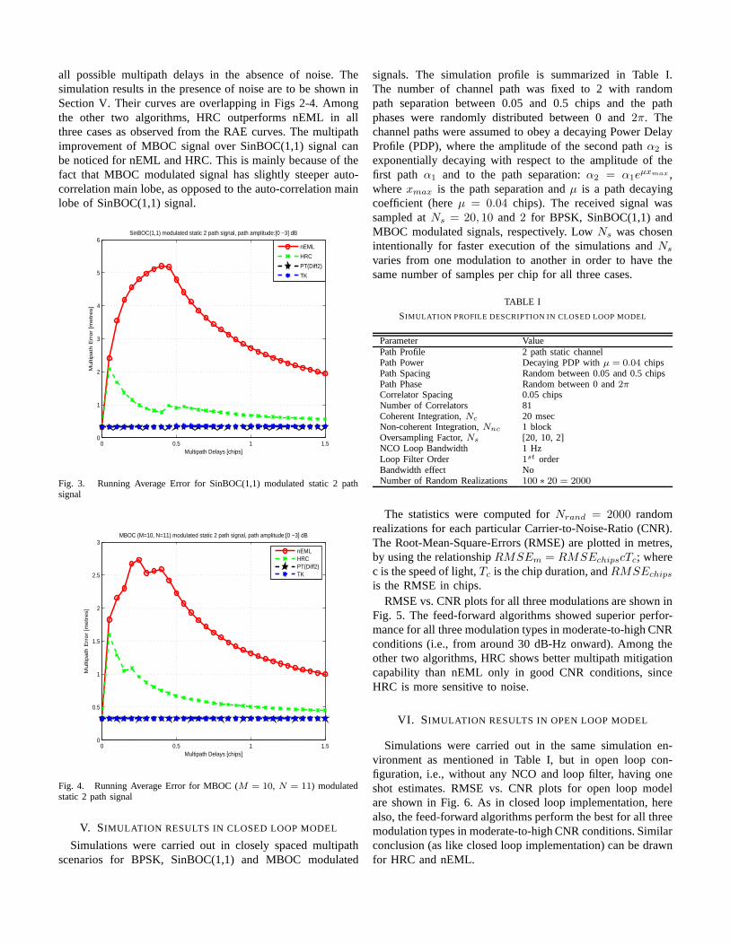
all possible multipath delays in the absence of noise. Thesimulation results in the presence of noise are to be shown inSection V. Their curves are overlapping in Figs 2-4. Amongthe other two algorithms, HRC outperforms nEML in allthree cases as observed from the RAE curves. The multipathimprovement of MBOC signal over SinBOC(1,1) signal canbe noticed for nEML and HRC. This is mainly because of thefact that MBOC modulated signal has slightly steeper auto-correlation main lobe, as opposed to the auto-correlation mainlobe of SinBOC(1,1) signal.
0 0.5 1 1.50
1
2
3
4
5
6
Multipath Delays [chips]
Mu
ltip
ath
Err
or
[me
tre
s]
SinBOC(1,1) modulated static 2 path signal, path amplitude:[0 −3] dB
nEML
HRC
PT(Diff2)
TK
Fig. 3. Running Average Error for SinBOC(1,1) modulated static 2 pathsignal
0 0.5 1 1.50
0.5
1
1.5
2
2.5
3
Multipath Delays [chips]
Mu
ltip
ath
Err
or
[me
tre
s]
MBOC (M=10, N=11) modulated static 2 path signal, path amplitude:[0 −3] dB
nEMLHRCPT(Diff2)TK
Fig. 4. Running Average Error for MBOC (M = 10, N = 11) modulatedstatic 2 path signal
V. SIMULATION RESULTS IN CLOSED LOOP MODEL
Simulations were carried out in closely spaced multipathscenarios for BPSK, SinBOC(1,1) and MBOC modulated
signals. The simulation profile is summarized in Table I.The number of channel path was fixed to 2 with randompath separation between 0.05 and 0.5 chips and the pathphases were randomly distributed between 0 and2π. Thechannel paths were assumed to obey a decaying Power DelayProfile (PDP), where the amplitude of the second pathα2 isexponentially decaying with respect to the amplitude of thefirst path α1 and to the path separation:α2 = α1e
µxmax ,wherexmax is the path separation andµ is a path decayingcoefficient (hereµ = 0.04 chips). The received signal wassampled atNs = 20, 10 and 2 for BPSK, SinBOC(1,1) andMBOC modulated signals, respectively. LowNs was chosenintentionally for faster execution of the simulations andNs
varies from one modulation to another in order to have thesame number of samples per chip for all three cases.
TABLE I
SIMULATION PROFILE DESCRIPTION IN CLOSED LOOP MODEL
Parameter ValuePath Profile 2 path static channelPath Power Decaying PDP withµ = 0.04 chipsPath Spacing Random between 0.05 and 0.5 chipsPath Phase Random between 0 and2πCorrelator Spacing 0.05 chipsNumber of Correlators 81Coherent Integration,Nc 20 msecNon-coherent Integration,Nnc 1 blockOversampling Factor,Ns [20, 10, 2]NCO Loop Bandwidth 1 HzLoop Filter Order 1st orderBandwidth effect NoNumber of Random Realizations 100 ∗ 20 = 2000
The statistics were computed forNrand = 2000 randomrealizations for each particular Carrier-to-Noise-Ratio(CNR).The Root-Mean-Square-Errors (RMSE) are plotted in metres,by using the relationshipRMSEm = RMSEchipscTc; wherec is the speed of light,Tc is the chip duration, andRMSEchips
is the RMSE in chips.RMSE vs. CNR plots for all three modulations are shown in
Fig. 5. The feed-forward algorithms showed superior perfor-mance for all three modulation types in moderate-to-high CNRconditions (i.e., from around 30 dB-Hz onward). Among theother two algorithms, HRC shows better multipath mitigationcapability than nEML only in good CNR conditions, sinceHRC is more sensitive to noise.
VI. SIMULATION RESULTS IN OPEN LOOP MODEL
Simulations were carried out in the same simulation en-vironment as mentioned in Table I, but in open loop con-figuration, i.e., without any NCO and loop filter, having oneshot estimates. RMSE vs. CNR plots for open loop modelare shown in Fig. 6. As in closed loop implementation, herealso, the feed-forward algorithms perform the best for all threemodulation types in moderate-to-high CNR conditions. Similarconclusion (as like closed loop implementation) can be drawnfor HRC and nEML.

20 25 30 35 40 45 5010
−1
100
101
102
103
CNR [dB−Hz]
RM
SE
[m
etr
es]
BPSK modulated signal in closed loop model
nEMLHRCPT(Diff2)TK
(a) BPSK signal
20 25 30 35 40 45 5010
−1
100
101
102
103
CNR [dB−Hz]
RM
SE
[m
etr
es]
SinBOC(1,1) modulated signal in closed loop model
nEMLHRCPT(Diff2)TK
(b) SinBOC(1,1) signal
20 25 30 35 40 45 5010
−1
100
101
102
103
CNR [dB−Hz]
RM
SE
[m
etr
es]
MBOC modulated signal in closed loop model
nEMLHRCPT(Diff2)TK
(c) MBOC signal
Fig. 5. RMSE vs. CNR plots for in closed loop model
20 25 30 35 40 45 5010
−1
100
101
102
103
CNR [dB−Hz]
RM
SE
[m
ete
rs]
BPSK modulated signal in open loop model
nEMLHRCPT(Diff2)TK
(a) BPSK signal
20 25 30 35 40 45 5010
−1
100
101
102
103
CNR [dB−Hz]
RM
SE
[m
ete
rs]
SinBOC(1,1) modulated signal in open loop model
nEMLHRCPT(Diff2)TK
(b) SinBOC(1,1) signal
20 25 30 35 40 45 5010
−1
100
101
102
103
CNR [dB−Hz]
RM
SE
[m
ete
rs]
MBOC modulated signal in open loop model
nEMLHRCPT(Diff2)TK
(c) MBOC signal
Fig. 6. RMSE vs. CNR plots for in open loop model

VII. C ONCLUSIONS
In this paper, the feed-forward techniques, previously pro-posed by the authors in [1], are implemented in closed loopconfiguration. The multipath performance of these algorithmsalong with the conventional DLLs for three different modula-tion types, including the newly proposed MBOC modulation,are presented in terms of running average error and RMSE.The results are then compared with the open loop counterpartfor observation. It is shown that the feed-forward algorithmsprovide much better multipath mitigation performance thanthe traditional DLLs in moderate-to-high CNRs for all threemodulated signals in both closed and open loop models. Itis also shown that the results in closed loop and open loopconfigurations are similar (closed loop results slightly better),which points out the fact that the feed-forward algorithmanalysis can be quite conveniently (i.e., faster) assertedin openloop configuration. The multipath improvement of MBOCsignal over BPSK and SinBOC(1,1) signals is also evidentfrom the simulation results (i.e. smaller RMSE values forMBOC signal as compared to other two signals).
ACKNOWLEDGEMENT
This work was carried out in the project “Future GNSSApplications and Techniques (FUGAT)” funded by the FinnishFunding Agency for Technology and Innovation (Tekes). Thiswork has also been supported by the Academy of Finland,which is gratefully acknowledged.
REFERENCES
[1] M. Z. H. Bhuiyan, E. S. Lohan, and M. Renfors. Code tracking algo-rithms for mitigating multipath effects in fading channelsfor satellite-based positioning.EURASIP Journal on Advances in Signal Processing,DOI: 10.1155/2008/863629, 2008.
[2] A. J. V. Dierendonck, P. C. Fenton, and T. Ford. Theory andPerformanceof Narrow Correlator Spacing in a GPS Receiver.Journal of The Instituteof Navigation, 39(3), June 1992.
[3] G. W. Hein, J.-A. Avila-Rodriguez, S. Wallner, A. R. Pratt, J. Owen,J. L. Issler, J. W. Betz, C. J. Hegarty, Lt. S. Lenahan, J. J. Rushanan,A. L. Kraay, and T. A. Stansell. MBOC: The new optimized spreadingmodulation recommended for GALILEO L1 OS and GPS L1C. InProceedings of Position, Location and Navigation Symposium 2006,IEEE/ION, pages 883–892, Apr 25-27 2006.
[4] X. Hu, E. S. Lohan, I. Groh, S. Sand, and M. Renfors. Multiplebranch Delay Lock Loop comparison for SinBOC(1,1) signal tracking inmultipath environments. InProceedings of ION International TechnicalMeeting, Jan 26-28 2009.
[5] H. Hurskainen, E. S. Lohan, X. Hu, J. Raasakka, and J. Nurmi. Multiplegate delay tracking structures for GNSS signals and their evaluation withSimulink, SystemC, and VHDL.International Journal of Navigationand Observation, DOI:10.1155/2008/785695, Article ID 785695, 2008.
[6] E.D. Kaplan and C. J. Hegarty.Understanding GPS: Principles andApplications, pages 173–183. Artech House, second edition, 2006.
[7] E. S. Lohan, A. Lakhzouri, and M. Renfors. Binary-Offset-Carriermodulation techniques with applications in satellite navigation systems.Wiley Journal of Wireless Communications and Mobile Computing, DOI:10.1002/ wcm.407, Jul 2006.
[8] E. S. Lohan and M. Renfors. Correlation properties of MultiplexedBinary Offset Carrier (MBOC) modulation. InProceedings of 13th
European Wireless Conference, Apr 1-4 2007.[9] E.S. Lohan, A. Lakhzouri, and M. Renfors. Feedforward delay estima-
tors in adverse multipath propagation for Galileo and modernized GPSsignals.EURASIP Journal of ASP, Article ID 50971, 2006.
[10] G. A. McGraw and M. S. Braasch. GNSS Multipath Mitigation UsingGated and High Resolution Correlator Concepts. InProceedings of theNational Technical Meeting of the Satellite Division of the Insitute ofNavigation, San Diego, USA, January 1999.
[11] A. Simsky, D. Mertens, J. M. Sleewaegen, W. D. Wilde, M. Hollreiser,and M. Crisci. MBOC vs. BOC(1,1) - Multipath Comparison Based onGIOVE-B Data. InsideGNSS, September/October 2008.

Publication P4
M. Z. H. Bhuiyan, E. S. Lohan and M. Renfors, “A Reduced Search Space
Maximum Likelihood Delay Estimator for Mitigating Multipath Effects in
Satellite-based Positioning” in Proc. of The 13th International Association
of Institute of Navigation World Congress, 27 - 30 October 2009, Stockholm,
Sweden.
Copyright c⃝2009 Nordic Institute of Navigation. Reprinted with permission.


Publication P5
M. Z. H. Bhuiyan, E. S. Lohan and M. Renfors, “A Slope-Based Multipath Es-
timation Technique for Mitigating Short-Delay Multipath in GNSS Receivers”
in Proc. of IEEE International Symposium on Circuits and Systems, pp.: 3573
- 3576, 30 May - 2 June 2010, Paris, France.
DOI= http://dx.doi.org/10.1109/ISCAS.2010.5537801
Copyright c⃝2010 IEEE. Reprinted with permission.
kulkki
Text Box
This material is posted here with permission of the IEEE. Such permission of the IEEE does not in any way imply IEEE endorsement of any of the Tampere University of Technology's products or services. Internal or personal use of this material is permitted. However, permission to reprint/republish this material for advertising or promotional purposes or for creating new collective works for resale or redistribution must be obtained from the IEEE by writing to [email protected]. By choosing to view this material, you agree to all provisions of the copyright laws protecting it.

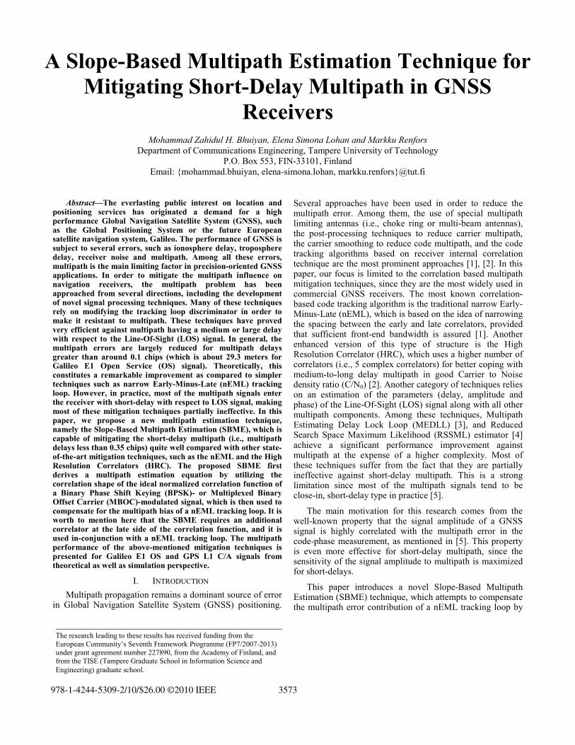
The research leading to these results has received funding from the European Community’s Seventh Framework Programme (FP7/2007-2013) under grant agreement number 227890, from the Academy of Finland, and from the TISE (Tampere Graduate School in Information Science and Engineering) graduate school.
A Slope-Based Multipath Estimation Technique for Mitigating Short-Delay Multipath in GNSS
Receivers
Mohammad Zahidul H. Bhuiyan, Elena Simona Lohan and Markku Renfors Department of Communications Engineering, Tampere University of Technology
P.O. Box 553, FIN-33101, Finland Email: mohammad.bhuiyan, elena-simona.lohan, [email protected]
Abstract—The everlasting public interest on location and positioning services has originated a demand for a high performance Global Navigation Satellite System (GNSS), such as the Global Positioning System or the future European satellite navigation system, Galileo. The performance of GNSS is subject to several errors, such as ionosphere delay, troposphere delay, receiver noise and multipath. Among all these errors, multipath is the main limiting factor in precision-oriented GNSS applications. In order to mitigate the multipath influence on navigation receivers, the multipath problem has been approached from several directions, including the development of novel signal processing techniques. Many of these techniques rely on modifying the tracking loop discriminator in order to make it resistant to multipath. These techniques have proved very efficient against multipath having a medium or large delay with respect to the Line-Of-Sight (LOS) signal. In general, the multipath errors are largely reduced for multipath delays greater than around 0.1 chips (which is about 29.3 meters for Galileo E1 Open Service (OS) signal). Theoretically, this constitutes a remarkable improvement as compared to simpler techniques such as narrow Early-Minus-Late (nEML) tracking loop. However, in practice, most of the multipath signals enter the receiver with short-delay with respect to LOS signal, making most of these mitigation techniques partially ineffective. In this paper, we propose a new multipath estimation technique, namely the Slope-Based Multipath Estimation (SBME), which is capable of mitigating the short-delay multipath (i.e., multipath delays less than 0.35 chips) quite well compared with other state-of-the-art mitigation techniques, such as the nEML and the High Resolution Correlators (HRC). The proposed SBME first derives a multipath estimation equation by utilizing the correlation shape of the ideal normalized correlation function of a Binary Phase Shift Keying (BPSK)- or Multiplexed Binary Offset Carrier (MBOC)-modulated signal, which is then used to compensate for the multipath bias of a nEML tracking loop. It is worth to mention here that the SBME requires an additional correlator at the late side of the correlation function, and it is used in-conjunction with a nEML tracking loop. The multipath performance of the above-mentioned mitigation techniques is presented for Galileo E1 OS and GPS L1 C/A signals from theoretical as well as simulation perspective.
I. INTRODUCTION Multipath propagation remains a dominant source of error
in Global Navigation Satellite System (GNSS) positioning.
Several approaches have been used in order to reduce the multipath error. Among them, the use of special multipath limiting antennas (i.e., choke ring or multi-beam antennas), the post-processing techniques to reduce carrier multipath, the carrier smoothing to reduce code multipath, and the code tracking algorithms based on receiver internal correlation technique are the most prominent approaches [1], [2]. In this paper, our focus is limited to the correlation based multipath mitigation techniques, since they are the most widely used in commercial GNSS receivers. The most known correlation-based code tracking algorithm is the traditional narrow Early-Minus-Late (nEML), which is based on the idea of narrowing the spacing between the early and late correlators, provided that sufficient front-end bandwidth is assured [1]. Another enhanced version of this type of structure is the High Resolution Correlator (HRC), which uses a higher number of correlators (i.e., 5 complex correlators) for better coping with medium-to-long delay multipath in good Carrier to Noise density ratio (C/N0) [2]. Another category of techniques relies on an estimation of the parameters (delay, amplitude and phase) of the Line-Of-Sight (LOS) signal along with all other multipath components. Among these techniques, Multipath Estimating Delay Lock Loop (MEDLL) [3], and Reduced Search Space Maximum Likelihood (RSSML) estimator [4] achieve a significant performance improvement against multipath at the expense of a higher complexity. Most of these techniques suffer from the fact that they are partially ineffective against short-delay multipath. This is a strong limitation since most of the multipath signals tend to be close-in, short-delay type in practice [5].
The main motivation for this research comes from the well-known property that the signal amplitude of a GNSS signal is highly correlated with the multipath error in the code-phase measurement, as mentioned in [5]. This property is even more effective for short-delay multipath, since the sensitivity of the signal amplitude to multipath is maximized for short-delays.
This paper introduces a novel Slope-Based Multipath Estimation (SBME) technique, which attempts to compensate the multipath error contribution of a nEML tracking loop by
978-1-4244-5309-2/10/$26.00 ©2010 IEEE 3573
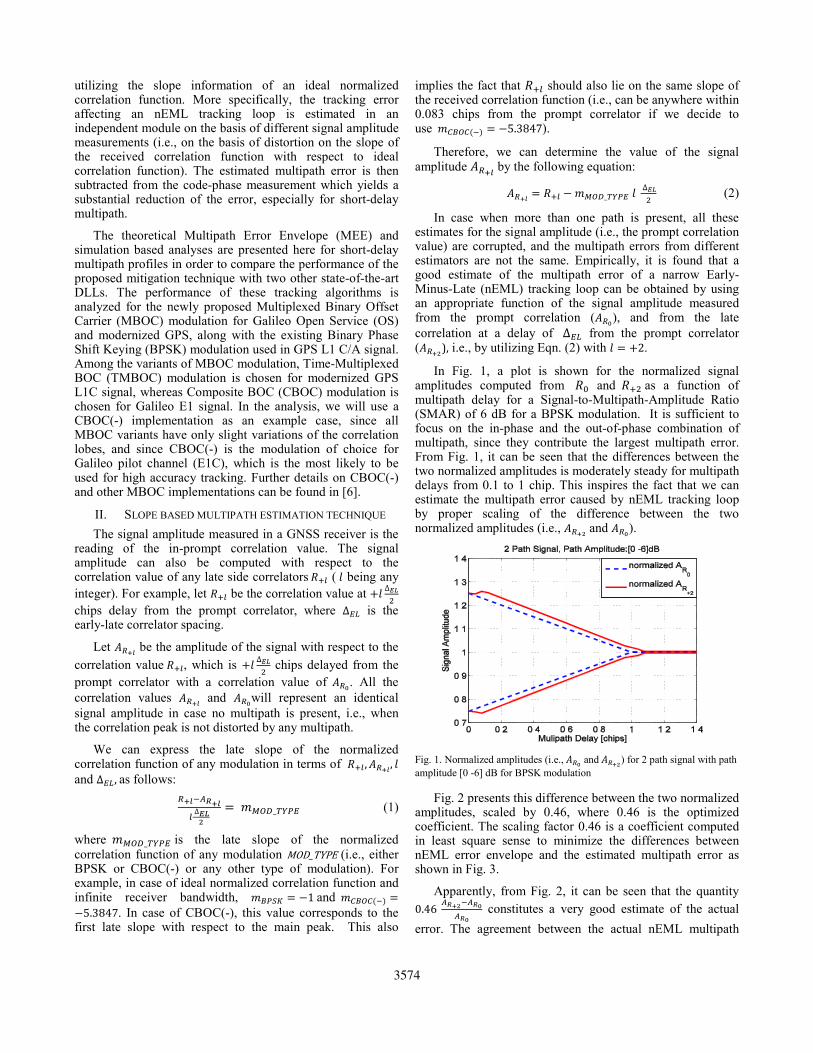
utilizing the slope information of an ideal normalized correlation function. More specifically, the tracking error affecting an nEML tracking loop is estimated in an independent module on the basis of different signal amplitude measurements (i.e., on the basis of distortion on the slope of the received correlation function with respect to ideal correlation function). The estimated multipath error is then subtracted from the code-phase measurement which yields a substantial reduction of the error, especially for short-delay multipath.
The theoretical Multipath Error Envelope (MEE) and simulation based analyses are presented here for short-delay multipath profiles in order to compare the performance of the proposed mitigation technique with two other state-of-the-art DLLs. The performance of these tracking algorithms is analyzed for the newly proposed Multiplexed Binary Offset Carrier (MBOC) modulation for Galileo Open Service (OS) and modernized GPS, along with the existing Binary Phase Shift Keying (BPSK) modulation used in GPS L1 C/A signal. Among the variants of MBOC modulation, Time-Multiplexed BOC (TMBOC) modulation is chosen for modernized GPS L1C signal, whereas Composite BOC (CBOC) modulation is chosen for Galileo E1 signal. In the analysis, we will use a CBOC(-) implementation as an example case, since all MBOC variants have only slight variations of the correlation lobes, and since CBOC(-) is the modulation of choice for Galileo pilot channel (E1C), which is the most likely to be used for high accuracy tracking. Further details on CBOC(-) and other MBOC implementations can be found in [6].
II. SLOPE BASED MULTIPATH ESTIMATION TECHNIQUE The signal amplitude measured in a GNSS receiver is the
reading of the in-prompt correlation value. The signal amplitude can also be computed with respect to the correlation value of any late side correlators ( being any integer). For example, let be the correlation value at ∆ chips delay from the prompt correlator, where ∆ is the early-late correlator spacing.
Let be the amplitude of the signal with respect to the correlation value , which is ∆ chips delayed from the prompt correlator with a correlation value of . All the correlation values and will represent an identical signal amplitude in case no multipath is present, i.e., when the correlation peak is not distorted by any multipath.
We can express the late slope of the normalized correlation function of any modulation in terms of , , and ∆ , as follows:
∆ _ (1)
where _ is the late slope of the normalized correlation function of any modulation MOD_TYPE (i.e., either BPSK or CBOC(-) or any other type of modulation). For example, in case of ideal normalized correlation function and infinite receiver bandwidth, 1 and 5.3847. In case of CBOC(-), this value corresponds to the first late slope with respect to the main peak. This also
implies the fact that should also lie on the same slope of the received correlation function (i.e., can be anywhere within 0.083 chips from the prompt correlator if we decide to use 5.3847).
Therefore, we can determine the value of the signal amplitude by the following equation:
_ ∆ (2)
In case when more than one path is present, all these estimates for the signal amplitude (i.e., the prompt correlation value) are corrupted, and the multipath errors from different estimators are not the same. Empirically, it is found that a good estimate of the multipath error of a narrow Early-Minus-Late (nEML) tracking loop can be obtained by using an appropriate function of the signal amplitude measured from the prompt correlation ( ), and from the late correlation at a delay of ∆ from the prompt correlator ( ), i.e., by utilizing Eqn. (2) with 2.
In Fig. 1, a plot is shown for the normalized signal amplitudes computed from and as a function of multipath delay for a Signal-to-Multipath-Amplitude Ratio (SMAR) of 6 dB for a BPSK modulation. It is sufficient to focus on the in-phase and the out-of-phase combination of multipath, since they contribute the largest multipath error. From Fig. 1, it can be seen that the differences between the two normalized amplitudes is moderately steady for multipath delays from 0.1 to 1 chip. This inspires the fact that we can estimate the multipath error caused by nEML tracking loop by proper scaling of the difference between the two normalized amplitudes (i.e., and ).
Fig. 1. Normalized amplitudes (i.e., and ) for 2 path signal with path amplitude [0 -6] dB for BPSK modulation
Fig. 2 presents this difference between the two normalized amplitudes, scaled by 0.46, where 0.46 is the optimized coefficient. The scaling factor 0.46 is a coefficient computed in least square sense to minimize the differences between nEML error envelope and the estimated multipath error as shown in Fig. 3.
Apparently, from Fig. 2, it can be seen that the quantity 0.46 constitutes a very good estimate of the actual error. The agreement between the actual nEML multipath
3574
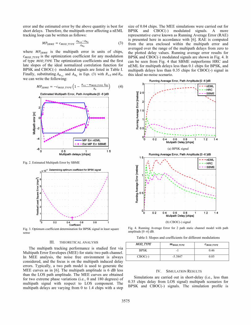
error and the estimated error by the above quantity is best for short delays. Therefore, the multipath error affecting a nEML tracking loop can be written as follows:
_ (3)
where is the multipath error in units of chips, _ is the optimization coefficient for any modulation of type MOD_TYPE. The optimization coefficients and the first late slopes of the ideal normalized correlation function for BPSK and CBOC(-) modulated signals are listed in Table I. Finally, substituting and in Eqn. (3) with and , we can write the following:
_ 1 _ ∆ (4)
Fig. 2. Estimated Multipath Error by SBME
Fig. 3. Optimum coefficient determination for BPSK signal in least square sense
III. THEORETICAL ANALYSIS The multipath tracking performance is studied first via
Multipath Error Envelopes (MEE) for static two path channel. In MEE analysis, the noise free environment is always considered, and the focus is on the multipath induced delay errors. Typically, a two path model is used to generate the MEE curves as in [6]. The multipath amplitude is 6 dB less than the LOS path amplitude. The MEE curves are obtained for two extreme phase variations (i.e., 0 and 180 degrees) of multipath signal with respect to LOS component. The multipath delays are varying from 0 to 1.4 chips with a step
size of 0.04 chips. The MEE simulations were carried out for BPSK and CBOC(-) modulated signals. A more representative curve known as Running Average Error (RAE) is presented here in accordance with [6]. RAE is computed from the area enclosed within the multipath error and averaged over the range of the multipath delays from zero to the plotted delay values. Running average error results for BPSK and CBOC(-) modulated signals are shown in Fig. 4. It can be seen from Fig. 4 that SBME outperforms HRC and nEML for multipath delays less than 0.1 chips for BPSK, and multipath delays less than 0.35 chips for CBOC(-) signal in this ideal no-noise scenario.
(a) BPSK signal
(b) CBOC(-) signal
Fig. 4. Running Average Error for 2 path static channel model with path amplitude [0 -6] dB.
Table I: Slopes and coefficients for different modulations MOD_TYPE _ _BPSK -1 0.46
CBOC(-) -5.3847 0.05
IV. SIMULATION RESULTS
Simulations are carried out in short-delay (i.e., less than 0.35 chips delay from LOS signal) multipath scenarios for BPSK and CBOC(-) signals. The simulation profile is
3575

summarized in Table II. Rayleigh fading channel model is used in the simulation. The number of channel path is fixed to 2 with random path separation between 0.04 and 0.35 chips. The channel paths are assumed to obey a decaying Power Delay Profile (PDP), where the amplitude of the second path
is exponentially decaying with respect to the amplitude of the first path and to the path separation: , where is the path separation and is a path decaying coefficient (here 0.1 chips). The received signal was sampled at 24 and 2 samples per BPSK and CBOC(-) interval, respectively. varies in order to have the same number of samples per chip for both the modulations.
The received signal duration is 800 milliseconds (ms) or 0.8 s for each particular C/N0 level. The tracking errors are computed after each msec (in this case, 20 ms) interval. In the final statistics, the first 600 ms are ignored in order to remove the initial error bias that may come from the acquisition stage. We run the simulations for 100 random realizations, which give a total of 10 1001000 statistical points, for each C/N0 level. The Root-Mean-Square-Errors (RMSE) are plotted in meters, by using the relationship ; where is the speed of light, is the chip duration, and is the RMSE in chips. RMSE vs. C/N0 plots are shown in Fig. 5. The SBME showed the best overall performance as compared to nEML and HRC in short-delay multipath scenarios. HRC is very sensitive to noise due to the extra pair of discriminations between the very-early and very-late gates, as compared to nEML and SBME.
TABLE II SIMULATION PROFILE DESCRIPTION
Parameter Value Path Profile 2 path Rayleigh channel Path Power Decaying PDP, 0.1 chips Path Spacing Random between 0.04 & 0.35 chips Path Phase Random between 0 and 2 Early-Late Spacing, ∆ 0.0833 chips Coherent Integration, 20 ms Non-coherent Integration, 1 block Oversampling Factor, [24, 2] Initial Delay Error 0.0833 chips Loop Filter Bandwidth 1 Hz Loop Filter Order 1st order Front-end Bandwidth Infinite
V. CONCLUSIONS In this paper, a novel multipath mitigation technique,
SBME was proposed and implemented in ideal infinite bandwidth case. The multipath performance of the newly proposed algorithm along with the conventional DLLs was studied in terms of running average error along with the simulated root-mean-square-error for short-delay multipath scenarios. It was shown that the SBME provided the best overall performance as compared to nEML and HRC in short-delay multipath scenarios. The authors are currently working on the adaptation of SBME in band-limited case, which is very demanding for GNSS mass-market receivers.
(a) BPSK signal
(b) CBOC(-) signal
Fig. 5. RMSE vs. C/N0 plots for 2 path Rayleigh channel model with multipath delay spacing between 0.04 and 0.35 chips.
REFERENCES [1] A. J. V. Dierendonck, P. C. Fenton, and T. Ford, “Theory and
Performance of Narrow Correlator Spacing in a GPS Receiver,” in Journal of The Institute of Navigation, 39(3), June 1992.
[2] G. A. McGraw and M. S. Braasch, “GNSS Multipath Mitigation Using Gated and High Resolution Correlator Concepts,” in Proceedings of the National Technical Meeting of the Satellite Division of the Insitute of Navigation, San Diego, USA, January 1999.
[3] R. D. J. Van Nee, J. Siereveld, P. Fenton and B. R. Townsend, “The Multipath Estimation Delay Lock Loop: Approaching Theoretical Limits,” in Proceedings of IEEE PLANS 1994, pages 246 – 251
[4] M. Z. H. Bhuiyan, E. S. Lohan and M. Renfors, “A Reduced Search Space Maximum Likelihood Delay Estimator for Mitigating Multipath Effects in Satellite-based Positioning,” in Proceedings of 13th International Association of Institute of Navigation, 2009 (IAIN’09), Stockholm, Sweden
[5] J. M. Sleewaegen and F. Boon, “Mitigating Short-Delay Multipath: a Promising New Technique,” in Proceedings of ION GPS 2001, Sep 11 – 14, 2001, Utah, USA
[6] G. W. Hein, J.-A. Avila-Rodriguez, S. Wallner, A. R. Pratt, J. Owen, J. L. Issler, J. W. Betz, C. J. Hegarty, Lt. S. Lenahan, J. J. Rushanan, A. L. Kraay and T. A. Stansell. MBOC: The new optimized spreading modulation recommended for GALILEO L1 OS and GPS L1C. In Proceedings of Position, Location and Navigation Symposium 2006, IEEE/ION, pages 883–892, Apr 25-27, 2006.
3576

Publication P6
M. Z. H. Bhuiyan, J. Zhang and E. S. Lohan, “Enhanced Delay Tracking
Performance of a C/N0-based Two-Stage Tracker for GNSS Receivers” in
Proc. of the European Navigation Conference on Global Navigation Satellite
Systems, 19-21 October 2010, Braunschweig, Germany.
Copyright c⃝ENC GNSS 2010. Reprinted with permission.


Publication P7
M. Z. H. Bhuiyan and E. S. Lohan, “Advanced Multipath Mitigation Tech-
niques for Satellite-based Positioning Applications” in International Journal
of Navigation and Observation, Vol. 2010, Article ID 412393, 15 pages.
DOI= http://dx.doi.org/10.1155/2010/412393
Copyright c⃝2010 Hindawi Publishing Corporation. This is an open access
article distributed under the Creative Commons Attribution License, which
permits unrestricted use, distribution, and reproduction in any medium, pro-
vided the original work is properly cited.


Hindawi Publishing CorporationInternational Journal of Navigation and ObservationVolume 2010, Article ID 412393, 15 pagesdoi:10.1155/2010/412393
Research Article
Advanced Multipath Mitigation Techniques forSatellite-Based Positioning Applications
Mohammad Zahidul H. Bhuiyan and Elena Simona Lohan
Department of Communications Engineering, Tampere University of Technology, P.O. Box 553, 33101 Tampere, Finland
Correspondence should be addressed to Mohammad Zahidul H. Bhuiyan, [email protected]
Received 9 June 2010; Revised 17 August 2010; Accepted 20 October 2010
Academic Editor: Olivier Julien
Copyright © 2010 M. Z. H. Bhuiyan and E. S. Lohan. This is an open access article distributed under the Creative CommonsAttribution License, which permits unrestricted use, distribution, and reproduction in any medium, provided the original work isproperly cited.
Multipath remains a dominant source of ranging errors in Global Navigation Satellite Systems (GNSS), such as the GlobalPositioning System (GPS) or the future European satellite navigation system Galileo. Multipath is generally considered undesirablein the context of GNSS, since the reception of multipath can make significant distortion to the shape of the correlation functionused for time delay estimation. However, some wireless communications techniques exploit multipath in order to provide signaldiversity though in GNSS, the major challenge is to effectively mitigate the multipath, since we are interested only in the satellite-receiver transit time offset of the Line-Of-Sight (LOS) signal for the receiver’s position estimate. Therefore, the multipath problemhas been approached from several directions in order to mitigate the impact of multipath on navigation receivers, including thedevelopment of novel signal processing techniques. In this paper, we propose a maximum likelihood-based technique, namely,the Reduced Search Space Maximum Likelihood (RSSML) delay estimator, which is capable of mitigating the multipath effectsreasonably well at the expense of increased complexity. The proposed RSSML attempts to compensate the multipath errorcontribution by performing a nonlinear curve fit on the input correlation function, which finds a perfect match from a set of idealreference correlation functions with certain amplitude(s), phase(s), and delay(s) of the multipath signal. It also incorporates athreshold-based peak detection method, which eventually reduces the code-delay search space significantly. However, the downfallof RSSML is the memory requirement which it uses to store the reference correlation functions. The multipath performance ofother delay-tracking methods previously studied for Binary Phase Shift Keying-(BPSK-) and Sine Binary Offset Carrier- (SinBOC-)modulated signals is also analyzed in closed loop model with the new Composite BOC (CBOC) modulation chosen for Galileo E1signal. The simulation results show that the RSSML achieves the best multipath mitigation performance in a uniformly distributedtwo-to-four paths Rayleigh fading channel model for all three modulated signals.
1. Introduction
Multipath remains a dominant source of ranging errors inGlobal Navigation Satellite Systems (GNSSs), such as theGlobal Positioning System (GPS) or the future Europeansatellite navigation system, Galileo. Several approaches havebeen used in order to reduce the multipath error. Amongthem, the use of special multipath-limiting antennas (i.e.,choke ring or multibeam antennas), the postprocessing tech-niques to reduce carrier multipath, the carrier smoothingto reduce code multipath, and the code-tracking algorithmsbased on receiver internal correlation technique are the mostprominent approaches [1]. In this paper, our focus is limitedto the correlation-based multipath mitigation techniques,
since they are the most widely used in commercial GNSSreceivers. The classical correlation-based code tracking struc-ture used in GNSS is based on a feedback delay estimatorand is implemented via a feedback loop. The most knownfeedback-delay estimator is the Delay Lock Loop (DLL) orEarly-Minus-Late (EML) loop, where two correlators spacedat one chip from each other are used in the receiver inorder to form a discriminator function, whose zero crossingsdetermine the path delays of the received signal [2–7]. Theclassical EML fails to cope with multipath propagation [1].Therefore, several enhanced EML-based techniques havebeen introduced in the literature for the last two decadesin order to mitigate the impact of multipath, especially inclosely spaced path scenarios. One class of these enhanced
2 International Journal of Navigation and Observation
EML techniques is based on the idea of narrowing thespacing between the early and late correlators, that is, narrowEML (nEML) or narrow correlator [1, 8, 9]. The choice ofcorrelator spacing depends on the receiver’s available front-end bandwidth along with the associated sampling frequency[10]. Correlator spacings in the range of 0.05 to 0.2 chips arecommercially available for nEML-based GPS receivers [11].
Another family of discriminator-based DLL variantsproposed for GNSS is the so-called Double-Delta (ΔΔ)technique, which uses more than 3 correlators in the trackingloop (typically, 5 correlators: two early, one in promptand two late) [8]. ΔΔ technique offers better multipathrejection in medium-to-long delay multipath [9, 12] ingood Carrier-to-Noise-density ratio (C/N0). Couple of well-known particular cases of ΔΔ technique are the HighResolution Correlator (HRC) [9], the Strobe Correlator(SC) [8, 13], the Pulse Aperture Correlator (PAC) [14],and the modified correlator reference waveform [8, 15].One other similar tracking structure is the Multiple GateDelay (MGD) correlator [16–19], where the number of earlyand late gates and the weighting factors used to combinethem in the discriminator are the parameters of the modeland can be optimized according to the multipath profile asillustrated in [12]. While coping better with the ambiguitiesof BOC correlation function, the MGD provides slightlybetter performance than the nEML at the expense of highercomplexity and is sensitive to the parameters chosen in thediscriminator function (i.e., weights, number of correlators,and correlator spacing) [12, 19]. In [12], it is also shown thatΔΔ technique is a particular case of MGD implementation.
Another tracking structure closely related to ΔΔ tech-nique is the Early1/Early2 (E1/E2) tracker, initially proposedin [20] and later described in [8]. In E1/E2 tracker, themain purpose is to find a tracking point on the correlationfunction that is not distorted by multipath. The first step isto locate two correlators on the early slope of the correlationfunction. The correlation values of these two early correlatorsare then compared with the correlation values of an idealreference correlation function. Finally, a delay-correctionfactor is computed based on the measured and referencecorrelation values of E1 and E2 correlators. As reported in[8], E1/E2 tracker shows some performance improvementover ΔΔ technique only for very short delay multipath forGPS L1 C/A signal (i.e., BPSK signal).
Another feedback-tracking structure is the Early-Late-Slope (ELS) [8], which is also known as Multipath Elim-ination Technique (MET) [21]. The ELS is based on twocorrelator pairs at both sides of the correlation function’scentral peak with parameterized spacing. Once both slopesare known, they can be used to compute a pseudorangecorrection that can be applied to the pseudorange measure-ment. However, simulation results performed in [8] showedthat ELS is outperformed by HRC with respect to MultipathError Envelopes (MEEs), for both BPSK and SinBOC(1,1)modulated signals.
A new multipath-estimation technique, named as A-Posteriori Multipath Estimation (APME), is proposed in[22], which relies on a posteriori estimation of the multipatherror tracking. Multipath error is estimated independently in
a multipath-estimator module on the basis of the correlationvalues from the prompt and very late correlators. Theperformance in multipath environment reported in [22] iscomparable with that of the SC: slight improvement for veryshort delays (i.e., delays less than 20 meters), but rathersignificant deterioration for medium delays. A similar slope-based multipath mitigation strategy, named as Slope-basedMultipath Estimator (SBME), was proposed by the authorsin [23]. SBME first derives a multipath estimation equationby utilizing the correlation shape of the ideal normalizedcorrelation function, which is then used to compensatefor the multipath bias of an nEML tracking loop. SBMErequires an additional correlator at the late side of thecorrelation function, and it is used in-conjunction with annEML tracking loop. It is reported in [23] that SBME hassuperior multipath mitigation performance than nEML inclosely spaced two paths channel model.
The conventional techniques, discussed so far can beclassified based on their correlator requirements as shown inFigure 1. For clarity reason, we use the notation correlator inthis paper in order to represent complex correlator (i.e., onecomplex correlator is equivalent to two correlators neededfor in-phase and quad-phase channels).
One of the most promising advanced multipath miti-gation techniques is the Multipath Estimating Delay LockLoop (MEDLL) [24–26] implemented by NovAtel for GPSreceivers. The MEDLL uses many correlators in order todetermine accurately the shape of the multipath corruptedcorrelation function. Then, a reference function is used in asoftware module in order to determine the best combinationof LOS and Non-LOS (NLOS) components (i.e., amplitudes,delays, phases, and number of multipath). However, MEDLLprovides superior long-delay multipath mitigation perfor-mance than nEML at the cost of expensive multicorrelator-based tracking structure. MEDLL is considered as a sig-nificant evolutionary step in the receiver-based attempt tomitigate-multipath. Moreover, MEDLL has stimulated thedesign of different maximum likelihood-based implemen-tations for multipath mitigation. One such variant is thenoncoherent MEDLL, developed by the authors, as describedin [27]. Classical MEDLL is based on a maximum likelihoodsearch, which is computationally extensive. The authorsimplemented a noncoherent version of MEDLL that reducesthe search space by incorporating a phase-search unit, basedon statistical distribution of multipath phases. However, theperformance of this suggested approach depends on thenumber of random phases considered; this means that thelarger the number is, the better the performance will be. Butthis will also increase the processing burden significantly. Theresults reported in [27] show that the noncoherent MEDLLprovides very good performance in terms of Root-Mean-Square-Error (RMSE), but has a rather poor Mean-Time-to-Lose-Lock (MTLL) as compared to the conventional DLLtechniques.
A new technique to mitigate multipath by means ofcorrelator reference waveform was proposed in [28]. Thistechnique, referred to as second derivative correlator, gen-erates a signal correlation function which has a muchnarrower width than a standard correlation function and

International Journal of Navigation and Observation 3
Conventionaltechniques
3 correlators 4 correlators 5 correlators 7 correlators
wEML nEML E1/E2 APME SBME ΔΔ ELS MET MGD
PACSCVEVLHRC
Figure 1: Classification of conventional multipath mitigation techniques based on correlator requirement.
is, therefore, capable of mitigating multipath errors over amuch wider range of secondary path delays. The narrowingof correlation function is accomplished by using a speciallydesigned code reference waveform (i.e., the negative of thesecond-order derivative of correlation function) instead ofthe ideal code waveform used in almost all existing receivers.However, this new technique reduces the multipath errors atthe expense of a moderate decrease in the effective Signal-to-Noise Ratio (SNR) due to the effect of narrowing thecorrelation function. A similar strategy, named as SlopeDifferential (SD), is based on second order derivative ofthe correlation function [29]. It is shown in [29] that thistechnique has better multipath performance than nEML andStrobe Correlator. However, the performance measure wassolely based on the theoretical MEE curves, thus its potentialbenefit in more realistic multipath environment is still anopen issue.
A completely different approach to mitigate multipatherror is used in NovAtel’s recently developed vision correlator[30]. The Vision Correlator (VC) is based on the concept ofMultipath Mitigation Technique (MMT) developed in [31].It can provide a significant improvement in detecting andremoving multipath signals as compared to other standardmultipath-resistant code-tracking algorithms (e.g., PAC ofNovAtel). However, VC has the shortcoming that it requiresa reference function shape to be used to fit the incoming datawith the direct path and the secondary path reference signals.The reference function generation has to be accomplished apriori, and it must incorporate the issues related to RadioFrequency (RF) distortions introduced by RF front end.
Several advanced multipath mitigation techniques werealso proposed by the authors in [27, 32]. While improvingthe delay-estimation accuracy, these techniques require ahigher number of correlators than the traditional DLL, andthey are sensitive to the noise-dependent threshold choice.Among these advanced techniques, two most competitiveones, previously proposed by the authors, are selected hereinfor performance comparison. These are Peak Tracking,based on 2nd-order Differentiation (PT(Diff2)), and Teager-Kaiser- (TK-) based delay estimation, the details of which canbe found in [27].
Many correlation-based multipath mitigation techniquesexist, but even the most promising ones (e.g., nEML, HRC,PT(Diff2), etc.) are not good enough for closely spaced mul-tipath environment, which is a key motivation for present-day researchers (as is the case in this research) to come upwith new innovative techniques. The purpose of this paper istwofold: first, to propose a novel maximum likelihood-basedReduced Search Space Maximum Likelihood (RSSML) delayestimator as an advanced multipath mitigation technique,mostly designed for harsh multipath environment (wherethere can be more than two strong closely spaced paths) andsecond, to analyze the performance of other contemporarymultipath mitigation techniques (both conventional andadvanced techniques) under the same unified simulationmodel. Additionally, the authors also develop a combinedTK- and nEML-based approach, named here as TK+nEML,which is less complex than TK, while at the same timeprovide better multipath mitigation than nEML. The moti-vation for such a combined approach will be discussed inmore detail in Section 4.2. The authors remark here thatthe basic idea of RSSML was first introduced in [33], whereRSSML was implemented for two paths channel with infinitebandwidth assumption. Moreover, the version of RSSMLpresented in [33] was not optimized in terms of memory,since it required a large set of correlation functions for allpossible delays in a predefined code delay window range. TheRSSML with its current version requires a large set of corre-lation functions only for the prompt correlator, and it is alsoadapted for finite bandwidth assumption for any numberof paths up to four. Simulation results in fading multipathenvironment are included in this paper in order to comparethe performance of the proposed techniques with the variousconventional DLLs and other developed advanced tech-niques (which are briefly reviewed here). The performanceof these techniques are analyzed for the newly definedComposite Binary Offset Carrier (CBOC) modulation alongwith the existing Binary Phase Shift Keying (BPSK) and SineBinary Offset Carrier (SinBOC) modulations.
The rest of this paper is organized as follows. Section 2presents the signal and channel model, followed by a descrip-tion on multicorrelator-based delay-tracking structure in

4 International Journal of Navigation and Observation
Section 3. The advanced multipath mitigation techniquesincluding the proposed RSSML are introduced in Section 4,followed by a detailed analysis on implementation issues forRSSML in Section 5. Section 6 shows the multipath perfor-mance of the selected techniques in terms of semianalyticalrunning average error. Section 7 presents the simulationresults in two-to-four paths fading channel model with finitefront-end bandwidth whereas Section 8 provides a compari-son between different techniques in terms of their multipathmitigation capability, relative complexity and needed a prioriinformation. Finally, some general conclusions are drawn inSection 9, with a perspective on future research direction.
2. Signal and Channel Model
Typical GNSS signals, such as those used in GPS orGalileo, employ the Direct Sequence-Code Division MultipleAccess (DS-CDMA) technique, where a PseudorandomNoise (PRN) code from a specific satellite is spreadingthe navigation data over SF chips (or over a code-epochlength) [34, 35]. In what follows, a baseband model isadopted for clarity reason. The estimation of code delay intoday’s receivers is typically done in digital domain usingthe baseband correlation samples. In the following, the timenotation t denotes the discrete time instant. The signal x(t)transmitted from one satellite with a specific PRN code canbe written as
x(t) =√Ebpmod(t)⊗ c(t), (1)
where Eb is the bit energy, pmod(t) is the modulationwaveform (i.e., BPSK for GPS L1 C/A code or CBOC(-) forGalileo E1C signals), and c(t) is the navigation data afterspreading as written below (spreading is done with a PRNcode of chip interval Tc and spreading factor SF)
c(t) =∞∑
n=−∞bn
SF∑
k=1
ck,nδ(t − nTcSF − kTc). (2)
Above δ(·) is the Dirac unit pulse, bn is the nth data bit (forpilot channels, bn = 1, ∀n), and ck,n is the kth chip (±1valued) corresponding to the nth spread bit.
The modulation waveform for BPSK or BOC can bewritten as [36]
pmod(t) = pTB (t)⊗NB−1∑
i=0
δ(t − iTB), (3)
where NB is BOC modulation order: NB = 1 for BPSKmodulation (BPSK can be seen as a particular case of BOCmodulation, as illustrated in [36]) and NB = 2 fsc/ fc, wherefsc is the subcarrier frequency and fc is the carrier frequencyfor BOC modulation, TB = Tc/NB is the BOC interval,and pTB (t) is the pulse-shaping filter (e.g., for unlimitedbandwidth case, pTB (t) is a rectangular pulse of width TB andunit amplitude).
The signal x(t) is typically transmitted over a multipathstatic or fading channel, where all interference sources except
the multipath are lumped into a single additive Gaussiannoise term η(t)
r(t) =L∑
l=1
αlx(t − τl)e j(2π fDt+θl) + η(t), (4)
where r(t) is the received signal, L is the number of channelpaths, αl is the amplitude of the lth path, θl is the phaseof the lth path, τl is the channel delay introduced bythe lth path (typically assumed to be slowly varying orconstant within the observation interval), fD is the Dopplershift introduced by the channel, and η(t) is a widebandadditive noise, incorporating all sources of interferences overthe channel. Assuming that the signal is sampled at Ns
samples per-chip (for BPSK) or per-BOC interval (for BOCmodulation), then the power spectral density of η(·) canbe written as N0/(NsNBSF), where N0 is the noise powerin 1 kHz bandwidth (i.e., bandwidth corresponding to onecode epoch). Generally, the SNR for any GNSS signal isexpressed with respect to the code epoch bandwidth Bw,under the name of Carrier-to-Noise-density ratio (C/N0).The relationship between (C/N0) and bit-energy-to-noiseratio (in dB) can be written as [37]
C
N0[dB-Hz] = Eb
N0+ 10 log10(Bw). (5)
The delay tracking is typically based on the code epoch-by-epoch correlation R(·) between the incoming signal andthe reference xref(·) modulated PRN code, with a certaincandidate Doppler frequency fD and delay τ
R(τ, fD,m
)= E
(1
Tsym
∫ mTsym
(m−1)Tsym
r(t)xref
(τ, fD
)dt
), (6)
where m is the code epoch index, Tsym is the symbol period(i.e., Tsym = SFTc), and E(·) is the expectation operator withrespect to the random variables (e.g., PRN code, channeleffects, etc.), and
xref
(τ, fD
)= pmod(t)⊗
∞∑n=−∞
SF∑
k=1
bnck,n
× δ(t − nTsym − kTc
)⊗ pTB (t)e− j2π fDt,
(7)
where bn is the estimated data bits. For Galileo signals, aseparate pilot channel is transmitted [34]. In what follows,
it is assumed that data bits are perfectly estimated (bn =bn), and removed before the correlation process. In apractical receiver, in order to cope with noise, coherent andnoncoherent integration can be used. The average coherent
correlation function Rc(τ, fD) can be written as
Rc
(τ, fD
)= 1Nc
Nc∑
m=1
R(τ, fD,m
), (8)
where Nc is the coherent integration time expressed in codeepochs or milliseconds for GPS or Galileo signal, and the

International Journal of Navigation and Observation 5
Frontend
NCO and PRNgenerator
Loopfilter
Carrierwipe-off · · ·
Correlator Discriminator
Bank of correlator
......
Figure 2: Block diagram for multicorrelator based DLL implemen-tation.
noncoherently averaged correlation function Rnc(τ, fD) canbe written as
Rnc
(τ, fD
)= 1Nnc
∑
Nnc
∣∣∣∣∣∣1Nc
Nc∑
m=1
R(τ, fD,m
)∣∣∣∣∣∣
pnc
, (9)
where Nnc is the noncoherent integration time expressed inblocks of length Nc milliseconds (for clarity reason, we avoidusing the block indexes for the noncoherent summations),and pnc is the power index used for noncoherent summation.The most encountered variants for pnc are: pnc = 1 (which isthe sum of absolute correlation values), and pnc = 2 (i.e.,which is the sum of squared-absolute correlation values).We prefer to use the later option (i.e., pnc = 2) in oursimulations.
3. Multicorrelator BasedDelay-Tracking Structure
Compared with the conventional EML tracking loop, whereonly three correlators are used (i.e., Early, Prompt and Late),here, in the multicorrelator-based structure, we generate abank of correlators (e.g., in this implementation, we use193 correlators with 0.0208 chips spacing between successivecorrelators) as presented in Figure 2. This large numberof correlators is needed in order to include the advancedmultipath mitigation techniques in the comparison, becausethese techniques make use of these correlators for estimatingthe channel properties while taking decision about the codedelay [27]. Some of these correlators can be kept inactiveor unused, for example when EML and HRC tracking loopsare used. After the necessary front-end processing, and afterthe carrier has wipedoff, the received postprocessed signalwas passed through a bank of correlators. As shown inFigure 2, the NCO and PRN generator block produces abank of early and late versions of replica codes based onthe delay of the LOS signal τ, the correlator spacing Δ,and the number of correlators M. In case of EML-trackingloop, the corresponding early-late spacing is equal to 2Δ.The received signal is correlated with each replica in thecorrelator bank, and the output of the correlator bank is avector of samples in the correlation envelope. Therefore, weobtain the correlation values for the range of ±MΔ chipsfrom the prompt correlator, where M is the number ofcorrelators and Δ is the correlator spacing between successivecorrelators. The various code tracking techniques (named as
discriminator in Figure 2) utilize the correlation values asinput, and generate the estimated LOS delay as output, whichis then smoothed by a loop filter. In accordance with [35],the implemented code loop filter is a 1st order filter, whosefunction can be written as
τ(k + 1) = τ(k) + γd(k), (10)
where γ is calculated based on loop filter bandwidth, Bn.A DLL loop bandwidth of 2 Hz is used in the simulation,assuming that carrier aiding is always available [9].
4. Advanced Multipath Mitigation Techniques
The advanced state-of-the-art multipath-mitigation tech-niques discussed in Section 1 are classified here based ontheir mitigation strategies, as shown in Figure 3. Theseadvanced techniques usually require a vast number ofcorrelators in order to estimate the channel characteristics,which are then used to mitigate the multipath effect. Severalmultipath-mitigation techniques introduced in past years arebased on Maximum Likelihood (ML) estimation principle.Examples of ML-based techniques include MEDLL [26],MMT [31], VC [30] of NovAtel, MEDLL of TampereUniversity of Technology (TUT) [27], and the proposedRSSML. Among other techniques, second derivative [28],slope differential [29], and PT(Diff2) [27] are based on2nd-order differentiation whereas TK, PT(TK) and TK +nEML are based on Teager Kaiser operator. In the followingsubsections, only those algorithms are elaborated, whichwill later be considered for performance analysis. It is niceto mention here that a brief discussion of the remainingalgorithms has already been presented in Section 1.
4.1. Teager Kaiser. The Teager Kaiser-based delay-estimationtechnique is based on the principle of extracting the signalenergy corresponding to various channel paths via the non-linear TK operator. The output ΨTK(x(n)) of TK operatorapplied to a discrete signal x(n), can be defined as [38]
ΨTK(x(n)) = x(n− 1)x∗(n− 1)
− 12
[x(n− 2)x∗(n) + x(n)x∗(n− 2)].(11)
The input of TK operator can be the noncoherent correlationfunction. The output of TK operator can indicate thepresence of a multipath component more clearly thanlooking directly at the correlation function. According to(11), at least 3 correlation values are needed to computeTK (in prompt, early, and very early). But usually, TK-baseddelay estimation utilizes a higher number of correlators andis sensitive to the noise dependent threshold choice. Firstly,it computes the noise variance according to the explanationpresented in Section 5.1, which is then used to compute anadaptive threshold as defined in [27]. The peaks which areabove the adaptive threshold are considered as competitivepeaks. Among all the competitive peaks, TK selects the delayassociated to that competitive peak which has the closestdelay difference from the previous delay estimate.

6 International Journal of Navigation and Observation
ML-basedtechniques
Othertechniques
Advancedtechniques
MEDLLof NovAtel
MMT, VCof NovAtel
RSSML
MEDLLof TUT
Diff2 based TK based Others
TrECPT (TK)
TK
TK + nEML
Secondderivative
PT (Diff2)
Slopedifferential
Figure 3: Classification of advanced techniques based on mitigation strategies.
TK-based technique is chosen in the context of the papersince it has been proved that it can give very good results inthe delay-estimation process when used with CDMA typeof signals, as presented in [27, 39]. Most recently, TK hasbeen studied also in closed-loop model for SinBOC(1,1),modulated two paths channel model, and its performancewas one of the best among the considered algorithms [40].One major limitation of TK-based technique is the fact thatthey are quite sensitive to the filtering stages (i.e., when infi-nite bandwidth is unavailable). The impact of the bandwidthlimitation on TK performance is seldomly addressed in theliterature, and hence, it is included in our algorithms’ list forperformance analysis under bandwidth limitation.
4.2. Combined Approach: Teager Kaiser and Narrow EML.A combined simplified approach with Teager Kaiser andnarrow EML is implemented in order to justify the feasibilityof having an nEML discrimination after the TK operationon the noncoherent correlation function. In this combinedapproach, TK operator is first applied to the noncoherentcorrelation function, and then nEML discrimination isapplied to the TK output. The motivation for this combinedapproach comes from the fact that, when we apply TKoperation to the noncoherent correlation function, it usuallymakes the main lobe of the noncoherent correlation function(after TK operation) much more steeper. This eventuallyreduces the effect of multipath in case of TK-based nEML(TK + nEML) as compared to nEML, as illustrated inFigure 4. In Figure 4, TK + nEML has a zero crossing at0.014 chips away from the true delay whereas nEML hasa zero crossing at 0.029 chips away from the true delay.Therefore, TK + nEML has superior multipath performance(around 4.1 meters of multipath error) as compared tonEML (around 8.5 meters of multipath error) for thisparticular scenario. On the contrary, TK+nEML restrictsthe code delay search range (i.e., the range where we expectour true code delay to be located) to be much narrower
−0.8
−0.6
−0.4
−0.2
0
0.2
0.4
0.6
0.8
S-cu
rve
−0.25 −0.2−0.15 −0.1 −0.05 0 0.05 0.1 0.15 0.2 0.25
SinBOC (1, 1) signal, path power: [0 −1.7372] dB
Code delay (chips)
nEMLTK + nEML
Figure 4: S-curve in SinBOC(1,1)- modulated 2 path Rayleighchannel model, path delay: [0 0.0833] chips, path power:[0–1.7372] dB, C/N0: 100 dB-Hz, BW: 24 MHz.
as compared to nEML, which eventually increases the riskfor the combined approach to lock at any of the false zerocrossings, in cases when the initial coarse delays are poorlyestimated.
4.3. Peak Tracking. Peak Tracking- (PT-) based techniques,namely, PT based on 2nd-order differentiation (PT(Diff2))and PT based on Teager Kaiser (PT(TK)), are first proposedin [27, 41]. Both of these techniques utilize the adaptivethreshold computed from the estimated noise varianceof the channel in order to decide on the correct codedelay. These advanced techniques first generate competitivepeaks which are above the computed adaptive threshold,

International Journal of Navigation and Observation 7
as explained in Sections 5.1 and 5.2. For each of thecompetitive peak, a decision variable is formed based on thepeak power, the peak position and the delay difference ofthe peak from the previous delay estimate. Finally, the PTtechniques select the peak which has the maximum weightas being the best LOS candidate. PT(Diff2) is included inour list of multipath mitigation techniques for performanceanalysis to be presented in Sections 6 and 7, since it hassuperior multipath mitigation performance over PT(TK)[27].
4.4. Reduced Search Space Maximum Likelihood DelayEstimator. In the presence of multipath, we recall thatthe received signal at the input of a GNSS receiver canbe expressed as in (4). We rewrite (4) below for furtherclarification
r(t) =L∑
l=1
αlx(t − τl)e j(2π fDt+θl) + η(t). (12)
In the above equation, as explained earlier, x(t) is the spread-spectrum code, η(t) is the white Gaussian noise, and αl,τl, θl are the amplitude, delay, and phase of the lth signal,respectively. For any GNSS signal, one of the most importantparameter of interest is the LOS code delay. A conventionalDLL (e.g., nEML) is not able to follow the LOS codedelay accurately, since it does not take into considerationthe bias contributed by the multipath components. Theproposed RSSML attempts to compensate the multipatherror contribution by estimating the multipath parametersalong with the LOS signal. If r(t) is observed for a certaintime Tcoh, that is short enough to assume that the parametersare constant, then the Maximum Likelihood Estimation(MLE) theory can be applied to estimate those parameters.The MLE principle states that the estimate of a certainparameter with the smallest mean square error is the estimatethat maximizes the conditional probability density functionof r(t). According to MLE, RSSML calculates the estimatedsignal parameters (i.e., path delays, path amplitudes, andpath phases), which minimize the mean square error of
L(τ, α, θ), as specified in
L(τ, a, θ
)=∫ tt−Tcoh
[r(t)− s(t)]2dt,
s(t) =L∑
l=1
αlx(t − τl)e j(2π fDt+θl).
(13)
Here, s(t) is the estimate of the LOS as well as multipathsignals, and we assume that the Doppler shift fD is correctly
estimated by the carrier tracking loop (i.e., fD = fD) and thatall the multipath components experience similar Dopplershift (i.e., fDl = fD). The first assumption is valid as long aswe are at the fine tracking stage (i.e., signal has been trackedfor a while). Equation (13) can be solved by setting the partial
derivatives of L(τ, α, θ) to zero. The resulting equations for
the lth signal can be written as follows in accordance with[25]:
τl =maxτ
⎡⎢⎢⎢⎢⎢⎢⎢⎢⎣
Re
⎧⎪⎪⎪⎪⎪⎪⎪⎪⎪⎨⎪⎪⎪⎪⎪⎪⎪⎪⎪⎩
⎡⎢⎢⎢⎢⎢⎢⎢⎢⎣Rrx(τ)−
L∑
n=1
n /=l
αnRideal(τ−τn)e jθn
⎤⎥⎥⎥⎥⎥⎥⎥⎥⎦e−jθl
⎫⎪⎪⎪⎪⎪⎪⎪⎪⎪⎬⎪⎪⎪⎪⎪⎪⎪⎪⎪⎭
⎤⎥⎥⎥⎥⎥⎥⎥⎥⎦
,
αl = Re
⎧⎪⎪⎪⎪⎪⎪⎪⎪⎪⎨⎪⎪⎪⎪⎪⎪⎪⎪⎪⎩
⎡⎢⎢⎢⎢⎢⎢⎢⎢⎣Rrx(τi)−
L∑
n = 1
n /= l
αnRideal(τl − τn)e jθn
⎤⎥⎥⎥⎥⎥⎥⎥⎥⎦e− jθl
⎫⎪⎪⎪⎪⎪⎪⎪⎪⎪⎬⎪⎪⎪⎪⎪⎪⎪⎪⎪⎭
⎤⎥⎥⎥⎥⎥⎥⎥⎥⎦
,
θl = arg
⎡⎢⎢⎢⎢⎢⎢⎢⎢⎣Rrx(τi)−
L∑
n = 1
n /= l
αnRideal(τl − τn)e jθn
⎤⎥⎥⎥⎥⎥⎥⎥⎥⎦.
(14)
In the above equations, Rrx(τ) is the received down-converted correlation function, and Rideal(τ) is the idealreference correlation function, the expression of which canbe found in [36]. Generally speaking, RSSML performs anonlinear curve fit on the input correlation function whichfinds a perfect match from a set of ideal reference correlationfunctions with certain amplitude(s), phase(s), and delay(s)of the multipath signal. Conceptually, a conventional spread-spectrum receiver does the same thing, but for only onesignal (i.e., the LOS signal). With the presence of multipathsignal, RSSML tries to separate the LOS component from thecombined signal by estimating all the signal parameters inMLE sense, which consequently achieves the best curve fit onthe received input correlation function. The total number ofpath components L is generally unknown to the receiver and,therefore, has to be estimated. One possible way to estimateL is to compute the mean square error for L = 1, 2, . . . ,Lmax
number of paths and select L with which we obtain theminimum mean square error. In this implementation, Lmax ischosen such that the total number of path components doesnot exceed 3 (i.e., Lmax = 3).
In a multicorrelator-based structure, the estimated LOSdelay, theoretically, can be anywhere within the code delaywindow range of ±τW chips, though in practice, it is quitelikely to have a delay error around the previous delayestimate. The code delay window range essentially dependson the number of correlators (i.e., M) and the spacingbetween the correlators (i.e., Δ) according to
τW = ± (M − 1)2
Δ. (15)
For example, if 193 correlators are used with a correlatorspacing of 0.0208 chips, then the resulting code-delay win-dow range will be±2 chips with respect to prompt correlator.

8 International Journal of Navigation and Observation
Therefore, the LOS delay estimate can be anywhere withinthis±2 chips window range. The ideal noncoherent referencecorrelation functions are generated for up to Lmax pathsonly for the middle delay index (i.e., ((M + 1)/2)th delayindex; for M = 193, the middle delay index is 97). Theseideal correlation functions for the middle delay index aregenerated offline and saved in a lookup table in memory.In real time, RSSML reads the correlation values fromthe lookup table, translates the ideal reference correlationfunctions at the middle delay index to the correspondingcandidate delay index within the code delay window, andthen computes the Minimum Mean Square Error (MMSE)for that specific delay candidate. Instead of consideringall possible LOS delays within a predefined code delaywindow as delay candidates, the search space is first reducedto some competitive peaks which are generated based onthe computed noise thresholds as explained in Section 5.This will eventually reduce the processing time required tocompute the MMSE (i.e., MMSE needs to be computed onlyfor the reduced search space).
5. Implementation Issues for RSSML
The implementation of RSSML is discussed here for betterclarification. Setting the partial derivatives of (13) to zeroyields a set of nonlinear equations, as presented in (14).To overcome the difficulty of solving these equations, theRSSML generates a set of ideal noncoherent referencecorrelation functions for the middle correlator of a certaincode-delay window range with various multipath delays,phases, and amplitudes. This means that, we generate s(t)in (13), by varying all multipath components for the middlecorrelator (e.g., the 97th correlator for a code-delay windowrange of ±2 chips with 0.0208 chips correlator spacing) ofthe code-delay window in order to obtain a discrete set ofideal noncoherent reference correlation functions. The set ofmultipath parameters can be specified as follows:
A = ∀a0 ≤ a ≤ 1,T = ∀τ0 ≤ τ ≤ 1,Θ = ∀θ0 ≤ θ ≤ 2π,
(16)
where |A| = p, |T| = q, and |Θ| = r are the cardinalitiesof the sets A,T , and Θ, respectively. The cardinality of eachset will depend on the resolution of the multipath parameterswithin the given range. However, the complexity will increaseas the cardinality of any set increases. The step-by-stepprocedure for RSSML is summarized below.
5.1. Step 1: Noise Estimation. The correlation values for earlytime delays (i.e., < −1 chip from the prompt correlator)are not affected by any multipath components since themultipath components are always delayed with respect to theLOS component. The noise level is estimated by taking themean out-of-1-chip values at the early side from the promptcorrelator of the normalized noncoherent correlation func-tion as explained in Figure 5.
0
0.1
0.2
0.3
0.4
0.5
0.6
0.7
0.8
0.9
1
Nor
mal
ised
non
-coh
eren
tco
rrel
atio
nfu
nct
ion
−2 −1.5 −1 −0.5 0 0.5 1 1.5 2
Path delay [0 −0.4167] chips,path power: [0 −3] dB, C/N0 : 100 dB-Hz
Delays (chips)
Peak threshold
Out-of-1-chipat early side
Figure 5: Noise estimation in SinBOC(1,1)- modulated 2 pathfading channel model, path delay: [0–0.4167] chips, path power:[0–3] dB, C/N0: 100 dB-Hz.
5.2. Step 2: Competitive Peak Generation. The competitivepeaks are those peaks which are generated based on the esti-mated noise level as obtained from step 1. A peak threshold iscomputed based on the estimated noise threshold plus someweighting factor as defined in [27]. The weighting factorsare chosen in such a way that they reduce the possible riskthat may arise due to the side lobes of the SinBOC(1,1)or CBOC(-) correlation. Therefore, the weighting factorschosen for SinBOC(1,1) and CBOC(-) modulations areslightly different from that of BPSK. It is worth to mentionhere that we use the same weighting factors for CBOC(-) andSinBOC(1,1) modulations, since they have almost similarcorrelation shape. As shown in Figure 5, in this examplecase, there is only one competitive peak which is above thecomputed peak threshold. The search space is then reducedfrom a large number of correlators to some competitive delaycandidates (serving here as competitive peaks).
5.3. Step 3: Reference Correlation Functions Reading andTranslation. The RSSML first reads the ideal noncoherentreference correlation functions (which are generated offlinefor the middle/prompt correlator) from the lookup table.Next, it translates the correlation functions at the middledelay index to the corresponding candidate delay indexwithin the code delay window for each competitive peak(which are already obtained from step 2). While doing thetranslation, RSSML truncates the ideal reference correlationvalues to zero which fall outside the code delay window range(i.e., correlation values outside ±2 chips from the middlecorrelator are truncated to zero).
5.4. Step 4: MMSE Computation. The RSSML computes theMMSE for each candidate delay index corresponding to acompetitive peak obtained from step 2.
5.5. Step 5: LOS Delay Estimation. The candidate delay indexwith the lowest MMSE is chosen as the estimated LOS delay.

International Journal of Navigation and Observation 9
6. Semianalytical Running Average Error
The most typical way to evaluate the performance of a mul-tipath mitigation technique is via Multipath Error Envelopes(MEE). Typically, two paths, either in phase or out of phase,are assumed to be present, and the multipath errors arecomputed for multipath delays up to 1.2 chips at maximum,since the multipath errors become less significant afterthat. The upper multipath error envelope can be obtainedwhen the paths are in phase and the lower multipath errorenvelope when the paths are out of phase (i.e., 180 phasedifference). In MEE analysis, several simplifying assumptionsare usually made in order to distinguish the performancedegradation caused by the multipath errors only. Suchassumptions include zero Additive-White-Gaussian-Noise(AWGN), ideal infinite-length PRN codes, and zero residualDoppler. Under these assumptions, the correlation Rrx(τ)between the reference code of modulation type MOD (e.g.,BPSK or CBOC(-)) and the received MOD-modulated signalvia an L-path channel can be written as
Rrx(τ) =L∑
l=1
αlejθlRMOD(τ − τl), (17)
where αl, θl, τl are the amplitude, phase, and delay, respec-tively, of the lth path; and RMOD(τ) is the autocorrelationfunction of a signal with modulation type MOD. Theanalytical expressions for MEEs become complicated in thepresence of more than two paths due to the complexityof channel interactions. Therefore, an alternative Monte-Carlo simulations-based approach is proposed herein formultipath error analysis in more than one path scenarios (i.e,for L ≥ 2). First, a sufficient number of random realizations,Nrandom are generated (i.e., in the simulations, we chooseNrandom equals to 2000), and then we look at absolute meanerror for each path delay over Nrandom points. The objectivehere is to analyze the multipath performance of varioustracking techniques in the presence of more than two channelpaths, which may occur in urban or indoor scenarios.
The following assumptions are made while running thesimulations for generating the curves of Running AverageError (RAE). The channel follows a decaying Power DelayProfile (PDP), which can be expressed by the equation:
αl = αl exp−μ(τl−τ1), (18)
where (τl−τ1) /= 0 for l > 1, μ is the PDP coefficient (assumedto be uniformly distributed in the interval [0.05; 0.1], whenthe path delays are expressed in samples). The channel pathphases θl are uniformly distributed in the interval [0; 2π],and the number of channel paths L is uniformly distributedbetween 2 and Lmax, where Lmax is set to 4 in the simulations.A constant successive path spacing xct is chosen in the range[0; 1.167] chips with a step of 0.0417 chips (which will definethe multipath delay axis in the running average error curves).It is worth to mention here that the number of paths reducedto one LOS path when xct = 0. The successive path delayscan be found using the formula τl = lxct in chips. Therefore,for each channel realization (which is a combination of
amplitudes −→α = α1, . . . ,αL, phases−→θ = θ1, . . . , θL, fixed
path spacings, and the number of channel paths L), a certain
LOS delay is estimated τ1(−→α ,−→θ ,L) from the zero crossing of
the discriminator function (i.e., D(τ) = 0), when searchedin the linear range of D(τ). The estimation error due to
multipath is τ1(−→α ,−→θ ,L) − τ1, where τ1 is the true LOS path
delay. The RAE curves are generated in accordance with [42].RAE is actually computed from the area enclosed within themultipath error and averaged over the range of the multipathdelays from zero to the plotted delay values. Therefore, inorder to generate the RAE curves, the absolute mean erroris computed for all Nrandom random points via
AME(xct) = mean(∣∣∣τ1
(−→α ,−→θ ,L
)− τ1
∣∣∣)
, (19)
where AME(xct) is the mean of absolute multipath error forthe successive path delay xct. Now, the running average errorfor each particular delay in the range [0;1.167] chips can becomputed as follows:
RAE(xct) =∑i
i=1 AME(xct)i
, (20)
where i is the successive path delay index and RAE(xct) is theRAE for the successive path delay xct. The RAE curves forthree different modulations are shown in Figure 6.
7. Simulation Results
The semianalytical results from Section 6 have also beenvalidated via simulations in fading multipath channels.Simulations have been carried out in closely spaced mul-tipath scenarios for BPSK-, SinBOC(1,1)-, and CBOC(-)-modulated signals for a finite front-end bandwidth. Thesimulation profile is summarized in Table 1. Rayleigh fadingchannel model is used in the simulation, where the numberof channel paths follows a uniform distribution between twoand four. The successive path separation is random between0.02 and 0.35 chips. The channel paths are assumed to obeya decaying PDP following (18), where μ = 0.1 (when thepath delays are expressed in samples). The received signal wassampled at Ns = 48, 24, and 4 for BPSK-, SinBOC(1,1)- andCBOC(-)- modulated signals, respectively. Ns varies in orderto have the same number of samples per chip for all the threecases.
The received signal duration is 800 milliseconds (ms)or 0.8 seconds for each particular C/N0 level. The trackingerrors are computed after each NcNnc ms (in this case,NcNnc = 20 ms) interval. In the final statistics, the first600 ms are ignored in order to remove the initial error biasthat may come from the delay difference between the receivedsignal and the locally generated reference code. Therefore,for the above configuration (i.e., code loop filter parametersand the first path delay of 0.2 chips), the leftover trackingerrors after 600 ms are mostly due to the effect of multipathonly, as shown in Figure 7. We run the simulations for100 random realizations, which give a total of 10 ∗ 100= 1000 statistical points, for each C/N0 level. The Root-Mean-Square-Errors (RMSE) of delay estimates are plotted
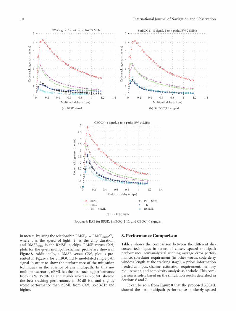
10 International Journal of Navigation and Observation
0
1
2
3
Cod
etr
acki
ng
erro
r(m
eter
s)
4
5
6
7
0 0.2 0.4 0.6 0.8 1 1.2 1.4
BPSK signal, 2-to-4 paths, BW 24 MHz
Multipath delay (chips)
(a) BPSK signal
0
1
2
3
Cod
etr
acki
ng
erro
r(m
eter
s)
4
5
6
7
0 0.2 0.4 0.6 0.8 1 1.2 1.4
SinBOC (1,1) signal, 2-to-4 paths, BW 24 MHz
Multipath delay (chips)
(b) SinBOC(1,1) signal
0
0.5
1
1.5
2
2.5
Cod
etr
acki
ng
erro
r(m
eter
s)
3
3.5
4
4.5
5
0 0.2 0.4 0.6 0.8 1 1.2 1.4
CBOC (−) signal, 2-to-4 paths, BW 24 MHz
Multipath delay (chips)
nEMLHRCTK + nEML
PT (Diff2)TKRSSML
(c) CBOC(-) signal
Figure 6: RAE for BPSK, SinBOC(1,1), and CBOC(-) signals.
in meters, by using the relationship RMSEm = RMSEchipscTc,where c is the speed of light, Tc is the chip duration,and RMSEchips is the RMSE in chips. RMSE versus C/N0
plots for the given multipath-channel profile are shown inFigure 8. Additionally, a RMSE versus C/N0 plot is pre-sented in Figure 9 for SinBOC(1,1)- modulated single pathsignal in order to show the performance of the mitigationtechniques in the absence of any multipath. In this no-multipath scenario, nEML has the best tracking performancefrom C/N0 35 dB-Hz and higher whereas RSSML showedthe best tracking performance in 30 dB-Hz, and slightlyworse performance than nEML from C/N0 35 dB-Hz andhigher.
8. Performance Comparison
Table 2 shows the comparison between the different dis-cussed techniques in terms of closely spaced multipathperformance, semianalytical running average error perfor-mance, correlator requirement (in other words, code delaywindow length at the tracking stage), a priori informationneeded as input, channel estimation requirement, memoryrequirement, and complexity analysis as a whole. This com-parison is solely based on the simulation results described inSections 6 and 7.
It can be seen from Figure 8 that the proposed RSSMLshowed the best multipath performance in closely spaced

International Journal of Navigation and Observation 11
−50
−40
−30
−20
−10
0
Trac
kin
ger
ror
(met
ers)
10
20
0 100 200 300 400 500 600 700 800
Tracking error for SinBOC (1, 1) signal
Initial convergence stage Error bias afterconvergence
Time (msec)
nEMLHRCTK + nEML
PT (Diff2)TKRSSML
Figure 7: One snapshot of delay tracking for SinBOC(1,1) signal in3 path fading channel with 24 MHz BW.
Table 1: Simulation profile description.
Parameter Value
Channel model Rayleigh fading channel
Number of paths (between 2 to 4)
Path power Decaying PDP with μ = 0.1
Path spacing Random between 0.02 and0.35 chips
Path phase Random between 0 and 2π
Oversampling factor, Ns [48, 24, 4]
E-L Spacing, ΔEL 0.0833 chips
Number of Correlators, M 193
Double-sided Bandwidth, BW 24 MHz
Filter type FIR
Filter order 6
Coherent integration, Nc 20 ms
Noncoherent integration, Nnc 1 block
Initial delay error ±0.1 chips
First path delay 0.2 chips
Code tracking loop bandwidth 2 Hz
Code tracking loop order 1st order
two to four paths fading channel model for all three mod-ulation types. All other techniques have varying multipathperformance with varying C/N0 and varying modulationtypes. In general, PT(Diff2) performs better for SinBOC(1,1)and CBOC(-) signals whereas HRC performs better for
all three modulations, but only in good C/N0 (i.e., 40 dB-Hz and higher). It is interesting to note here that all thetechniques except the proposed RSSML tend to show similarperformance (within few meters of error bounds) in this twoto four paths fading channel profile with a reasonably highPDP factor 0.1, as seen in Figure 8.
The semianalytical RAE performance is shown inFigure 6. It is obvious from Figure 6 that the proposedRSSML showed superior performance in terms of RAEas compared to other techniques in this no noise two tofour paths static channel model. Among other techniques,PT(Diff2) and TK showed very good performance followedby HRC and TK + nEML. The RAE analysis is quitetheoretical from two perspectives: firstly, the delay estimationis a one-shot estimate and does not really include anytracking loop in the process, and secondly, the analysis isusually carried out with ideal noise free assumption. Thesefacts probably explain the reason why an algorithm whichperforms very good with respect to RAE may not necessarilyprovide the same performance in more realistic closed-loopfading channel model, especially in the presence of morethan two channel paths. However, MEE or RAE analysis hasbeen widely used by the research community as an importanttool for analyzing the multipath performance due to simplerimplementation and also due to the fact that it is hard toisolate multipath from other GNSS error sources in real life.
The complexity of any multipath mitigation techniquemainly depends on the correlation structure and the imple-mentation issues concerning channel estimation, correlatorrequirement, required number of mathematical operations,memory requirement, and so on. The advanced mitigationtechniques are usually complex, since they generally utilizea large number of correlators for channel estimation, whichare then used to estimate the first arriving path delay. Amongthe advanced techniques, the proposed RSSML is the mostcomplex one, since it requires a large set of reference cor-relation functions which are generated offline to be used asa-priori information while estimating the code delay of firstarriving path (please visit Section 5 for details). The memorysize will eventually depend on few factors including themaximum number of paths to be considered, the correlatorspacing, the number of correlators and the resolution ofeach multipath parameter (i.e., path delays, path phases, andpath amplitudes). In the current MATLAB implementation,the RSSML requires approximately 14 megabytes of memoryfor each particular modulation with maximum number ofpaths set to 3, the correlator spacing set to 0.0208 chips, thenumber of correlators for window length of 4 chips set to 193.However, it is possible to reduce the memory requirementby adjusting the parameters appropriately. The impact ofmemory optimization is not analyzed here, and hence, it iskept open for future research.
9. Conclusions
Multipath is one of the major dominant sources in high-precision-oriented GNSS applications. Many receiver archi-tectures exist in the market which employ a variety of

12 International Journal of Navigation and Observation
10
20
30
40
50
RSM
E(m
eter
s)
60
70
0 35 40 45
BPSK signal, 2 to 4 paths, BW 24 MHz
C/N0 (dB-Hz)
(a) BPSK signal
10
15
20
25
30
35
40
45
RSM
E(m
eter
s)
50
55
0 35 40 45
SinBOC (1,1) signal, 2 to 4 paths, BW 24 MHz
C/N0 (dB-Hz)
(b) SinBOC(1,1) signal
0
10
20
30
40
RSM
E(m
eter
s)
50
60
70
0 35 40 45
CBOC (−) signal, 2 to 4 paths, BW 24 MHz
C/N0 (dB-Hz)
nEMLHRCTK + nEML
PT (Diff2)TKRSSML
(c) CBOC(-) signal
Figure 8: RMSE versus C/N0 plots for 2 to 4 paths Rayleigh fading channel in 24 MHz BW.
multipath mitigation techniques. Most of these techniquesprovide very good multipath mitigation for medium-to-longdelay multipath. However, the multipath studies presentedin most of the research papers are based on only twopaths assumption, which is rather optimistic. In this study,a novel Reduced Search Space Maximum Likelihood delayestimator was proposed and the multipath performance wasstudied for short delay multipath where the number of pathsvaried between two and four. The multipath performanceof the newly proposed technique along with the state-of-the-art DLLs, and other advanced techniques were presentedvia running average error sense and also via root-mean-square-error sense. Three different modulation types wereconsidered including the newly proposed CBOC modulation(chosen as the modulation technique for Galileo E1 signal).
It was shown that the RSSML, in general, achieved thebest multipath mitigation performance for all three differentsignals in this two-to-four paths closely spaced multipathprofile. Simulation results show that the proposed RSSMLoffers a viable solution by increasing the position accuracyin the presence of closely spaced multipath, especially indense urban areas where the number of significant pathscan be higher than two. On the contrary, the proposedmethod increases the receiver complexity, since it is basedon multicorrelator-based structure, and at the same time, itrequires a good amount of memory to keep the referencenoncoherent correlation functions available for computingthe MMSE. Therefore, RSSML and other advanced multipathmitigation techniques presented here are more suitable forprofessional receivers due to their relatively high complexity

International Journal of Navigation and Observation 13
Table 2: Comparative performance of multipath mitigation techniques.
nEML HRC TK + nEML PT(Diff2) TK RSSML
Closely spacedmultipathperformance
Moderate Good Moderate Good Moderate Best
Running averageerror performance
Fair Good Good Very Good Very Good Best
Correlatorrequirement (No. ofCorr.)
Few (3) Few (5) Few (5) Many (100+) Many (100+) Many (100+)
A priori informationCoarse delayestimate
Coarse delayestimate
Coarse delayestimate
Coarse delayestimate
Coarse estimatedelay
A large set ofreferencecorrelationfunctions
Channel estimationrequired?
No No NoYes (noisecomputation)
Yes (noisecomputation)
Yes (noisecomputation)
Memory requirement None None None None None High
Complexity Low Low Moderate Fair Fair High
0
5
10
15
20
RSM
E(m
eter
s) 25
30
35
40
0 35 40 45
SinBOC (1, 1) signal path channel, BW 24 MHz
C/N0 (dB-Hz)
nEMLHRCTK + nEML
PT (Diff2)TKRSSML
Figure 9: RMSE versus C/N0 plot for single path SinBOC(1,1)signal in 24 MHz BW.
whereas for mass-market receivers, nEML and HRC are stillthe best tradeoff between performance and complexity.
Acknowledgments
This work was carried out in the project “Future GNSSApplications and Techniques (FUGAT)” funded by theFinnish Funding Agency for Technology and Innovation(Tekes). This work has also been supported by the Academyof Finland, which is gratefully acknowledged. The authorswould also like to thank Nokia Foundation and TampereDoctoral Programme in Information Science and Engineer-ing (TISE) for their financial support.
References
[1] A. J. V. Dierendonck, P. Fenton, and T. Ford, “Theory andperformance of narrow correlator spacing in a GPS receiver,”Journal of the Institute of Navigation, vol. 39, no. 3, pp. 265–283, 1992.
[2] G. Fock, J. Baltersee, P. Schulz-Rittich, and H. Meyr, “Channeltracking for rake receivers in closely spaced multipath envi-ronments,” IEEE Journal on Selected Areas in Communications,vol. 19, no. 12, pp. 2420–2431, 2001.
[3] P. Fine and W. Wilson, “Tracking algorithms for GPS offsetcarrier signals,” in Proceedings of the ION National TechnicalMeeting, January 1999.
[4] J. Baltersee, G. Fock, and P. Schulz-Rittich, “Adaptive code-trackingreceiver for direct-sequence Code Division MultipleAccess (CDMA)communications over multipath fading chan-nels and method for signalprocessing in a RAKE receiver,” USPatent Application Publication, US2001/0014114 A1 (LucentTechnologies), August 2001.
[5] R. Bischoff, R. Hab-Umbach, W. Schulz, and G. Heinrichs,“Employment of a multipath receiver structure in a combinedGALILEO/UMTS receiver,” in Proceedings of the 55th VehicularTechnology Conference (VTC ’02), pp. 1844–1848, May 2002.
[6] K. Chen and L. D. Davisson, “Analysis of SCCL as a PN-codetracking loop,” IEEE Transactions on Communications, vol. 42,no. 11, pp. 2942–2946, 1994.
[7] M. Laxton, -Analysis and simulation of a new code trackingloopfor GPS multipath mitigation, M.S. thesis, Air ForceInstitute of Technology, 1996.
[8] M. Irsigler and B. Eissfeller, “Comparison of multipathmitigation techniques with consideration of future signalstructures,” in Proceedings of the 16th International TechnicalMeeting of the Satellite Division of the Institute of Naviga-tion (ION GNSS ’03), pp. 2584–2592, Portland, Ore, USA,September 2003.
[9] G. A. McGraw and M. S. Braasch, “GNSS multipath mitigationusing gated and high resolution correlator concepts,” inProceedings of the he National Technical Meeting of the SatelliteDivision of the Insitute of Navigation, San Diego, Calif, USA,January 1999.

14 International Journal of Navigation and Observation
[10] J. W. Betz and K. R. Kolodziejski, “Extended theory of early-late code tracking for a bandlimited GPS receiver,” Navigation,Journal of the Institute of Navigation, vol. 47, no. 3, pp. 211–226, 2000.
[11] M. S. Braasch, “Performance comparison of multipath mit-igating receiver architectures,” in Proceedings of the IEEEAerospace Conference, pp. 31309–31315, Big Sky, Mont, USA,March 2001.
[12] H. Hurskainen, E. S. Lohan, X. Hu, J. Raasakka, and J. Nurmi,“Multiple gate delay tracking structures for GNSS signalsand their evaluation with Simulink, SystemC, and VHDL,”International Journal of Navigation and Observation, vol. 2008,Article ID 785695, 17 pages, 2008.
[13] Garin and Rousseau, “Enhanced strobe correlator multipathrejection for code & carrier,” in Proceedings of the 10thInternational Technical Meeting of the Satellite Division of theInstitute of Navigation (ION GPS ’97), vol. 1, pp. 559–568,Kansas City, Mo, USA, September 1997.
[14] J. Jones, P. Fenton, and B. Smith, “Theory and performanceof the pulse aperture correlator,” Tech. Rep., Novatel, Alberta,Canada, September 2004.
[15] L. R. Weill, “Multipath mitigation—how good can it get withnew signals?” GPS World, vol. 16, no. 6, pp. 106–113, 2003.
[16] R. Fante, “Unambiguous tracker for GPS binary-offset carriersignals,” in Proceedings of the National Technical Meeting ofthe Institute of Navigation (ION NTM ’03), Albuquerque, NM,USA, 2003.
[17] R. Fante, “Unambiguous first-order tracking loop M-Code,”MITRE Technical Report MTR 94B0000040, July 2004.
[18] P. A. Bello and R. L. Fante, “Code tracking performancefor novel unambiguous M-Code time discriminators,” inProceedings of the National Technical Meeting of the Instituteof Navigation (ION NTM ’05), pp. 293–298, San Diego, Calif,USA, January 2005.
[19] M. Z. H. Bhuiyan, Analyzing code tracking algorithms forgalileo open service signal, M.S. thesis, Tampere University ofTechnology, August 2006.
[20] A. J. V. Dierendonck and M. S. Braasch, “Evaluation of GNSSreceiver correlation processing techniques for multipath andnoise mitigation,” in Proceedings of the National TechnicalMeeting of the Institute of Navigation (ION NTM ’97), pp. 207–215, Santa Monica, Calif, USA, January 1997.
[21] Townsend and Fenton, “Practical approach to the reductionof pseudorange multipath errors in a L1 GPS receiver,” inProceedings ofthe 7th International Technical Meeting of theSatellite Division of theInstitute of Navigation (ION-GPS ’94),vol. 1, pp. 143–148, Salt Lake City, Utah, USA, September1994.
[22] J. M. Sleewaegen and F. Boon, “Mitigating short-delaymultipath: apromising new technique,” in Proceedings of theInternational Technical Meeting of the Satellite Division of theInstitute of Navigation (ION GPS ’01), pp. 204–213, Salt LakeCity, Utah,USA, September 2001.
[23] M. Z.H. Bhuiyan, E. S. Lohan, and M. Renfors, “A slope-based multipath estimation technique for mitigating short-delay multipath in GNSS receivers,” in Proceedings of the IEEEInternational Symposium on Circuits and Systems (ISCAS ’10),pp. 3573–3576, 2010.
[24] R. D. J. V. Nee, “The multipath estimating delay lock loop,” inProceedings of the IEEE 2nd International Symposium on SpreadSpectrum Techniques and Applications, pp. 39–42, Yokohama,Japan, november 1992.
[25] Richard D. J. van Nee, Siereveld, Patrick C. Fenton, andBryan R. Townsend, “Multipath estimating delay lock loop:approaching theoretical accuracy limits,” in Proceedings of theIEEE PLANS, Position Location and Navigation Symposium,vol. 1, pp. 246–251, 1994.
[26] B. Townsend, D. J. R. van Nee, P. Fenton, and K. Van Dieren-donck, “Performance evaluation of the multipath estimatingdelay lock loop,” in Proceedings of the National TechnicalMeeting, pp. 277–283, Anaheim, Calif, USA, January 1995.
[27] M. Z. H. Bhuiyan, E. S. Lohan, and M. Renfors, “Code trackingalgorithms for mitigating multipath effects in fading channelsfor satellite-based positioning,” EURASIP Journal on Advancesin Signal Processing, vol. 2008, Article ID 863629, 2008.
[28] Lawrence R. Weill, “GPS multipath mitigation by means ofcorrelator reference waveform design,” in Proceedings of theNational Technical Meeting, Institute of Navigation (NTM ’97),pp. 197–206, Santa Monica, Calif, USA, January1997.
[29] C. Lee, S. Yoo, S. Yoon, and S. Y. Kim, “A novel multipath mit-igation scheme based on slope differential of correlator outputfor Galileo systems,” in Proceedings of the 8th InternationalConference Advanced Communication Technology (ICACT ’06),vol. 2, pp. 1360–1363, February 2006.
[30] P. C. Fenton and J. Jones, “The theory and performance ofNovAtel Inc.’s Vision Correlator,” in Proceedings of the 18thInternational Technical Meeting of the Satellite Division of TheInstitute of Navigation (ION GNSS ’05), pp. 2178–2186, LongBeach, Calif, USA, September 2005.
[31] L. Weill, “Multipath mitigation using modernized GPS signals:how good can it get?” in Proceedings of the InternationalTechnical Meeting of the Satellite Division of the Institute ofNavigation (ION GPS ’02), pp. 493–505, Palm Springs, Calif,USA, September 2002.
[32] E. S. Lohan, A. Lakhzouri, and M. Renfors, “Feedforward delayestimators in adverse multipath propagation for galileo andmodernized GPS signals,” EURASIP Journal on Applied SignalProcessing, vol. 2006, Article ID 50971, 2006.
[33] M. Z. H Bhuiyan, E. S. Lohan, and M. Renfors, “A reducedsearch space maximum likelihood delay estimator for mit-igating multipath effects in satellite-based positioning,” inProceedings of the 13th International Association of Institute ofNavigation, October 2009.
[34] European Space Agency, “Galileo Open Service Signal In SpaceInterface Control Document,” OS SIS ICD, Draft 1, February2008.
[35] E. Kaplan and C. J. Hegarty, Understanding GPS: Principlesand Applications, Artech House, Norwood, Mass, USA, 2ndedition, 2006.
[36] E. S. Lohan, A. Lakhzouri, and M. Renfors, “Binary-Offset-Carrier modulation techniques with applications in satellitenavigation systems,” Wireless Communications and MobileComputing, vol. 7, no. 6, pp. 767–779, 2007.
[37] M. S. Braasch and A. J. Van Dierendonck, “GPS receiverarchitectures and measurements,” Proceedings of the IEEE, vol.87, no. 1, pp. 48–64, 1999.
[38] R. Hamila, E. S. Lohan, and M. Renfors, “Subchip multipathdelay estimation for downlink WCDMA system based onTeager-Kaiser operator,” IEEE Communications Letters, vol. 7,no. 1, pp. 1–3, 2003.
[39] E. S. Lohan, R. Hamila, A. Lakhzouri, and M. Renfors,“Highly efficient techniques for mitigating the effects ofmultipath propagation in DS-CDMA delay estimation,” IEEETransactions on Wireless Communications, vol. 4, no. 1, pp.149–162, 2005.
International Journal of Navigation and Observation 15
[40] M. Z. H. Bhuiyan, E. S. Lohan, and M. Renfors, “Multipathmitigation performance of multi-correlator based code track-ing algorithms in closedand open loop model,” in Proceedingsof the The 15th European Wireless Conference, pp. 84–89, May2009.
[41] M. Z. H. Bhuiyan, E. S. Lohan, and M. Renfors, “Peak trackingalgorithm for Galileo-based positioning in multipath fadingchannels,” in Proceedings of the IEEE International Conferenceon Communications (ICC ’07), pp. 5927–5932, June 2007.
[42] G. W. Hein, J.-A. Avila-Rodriguez, S. Wallner et al., “MBOC:the new optimized spreading modulation recommended forGALILEO L1 OS and GPS L1C,” in Proceedings of IEEEPosition, Location and Navigation Symposium (ION PLANS’06), pp. 883–892, April 2006.

Publication P8
E. S. Lohan, M. Z. H. Bhuiyan and H. Hurskainen, “Performance of Multi-
plexed Binary Offset Carrier Modulations for Modernized GNSS Systems” in
GPS World, Innovation Column, June 2011.
Copyright c⃝2011 GPS World. Reprinted with permission.