ANALYSIS OF ISENTROPIC EFFICIENCY AND … Word - IJSR101.pdf · Inlet air volumetric Flow ......
13
Indian J.Sci.Res.1(2) : 720-732, 2014 ISSN:2250-0138(Online) ISSN : 0976-2876 (Print) __________________________________ 1 Corresponding author ANALYSIS OF ISENTROPIC EFFICIENCY AND PRESSURE RATIO IN A THREE-STAGE CENTRIFUGAL COMPRESSOR BY THERMODYNAMIC MODELING AND NEURAL NETWORK MODELING ALGORITHM SAYED IMAN ALAVI 1a , SAYED EHSAN ALAVI b , MAJID GHOLAMI c , SHAHAB GHOLAMI d , SAYED AMIN ALAVI e ab Department of Mechanic, Shoushtsar Branch, Islamic azad university, shoushtar, Iran c Dr.Shariaty College,Technical& Vocational University,Tehran,Iran d Mechanic Engineer,FajrPetrochemical Company,Mahshahr,Iran e Petroleum Engineer, National Iranian South oil Company,Ahwaz,Iran ABSTRACT In this research, a three-stage centrifugal compressor with two intercoolers has been studied. According to experimental data which were taken every moment in the control room, the compressor has been modeled by using neural network modeling Algorithm and governing thermodynamic equations. According to governing thermodynamic equations, the effect of inlet air temperature to every Compression stages on isentropic efficiency was studied. During the study,it was found that, in first stage,isentropic efficiencyis between 67.16 – 75.36 and in second stage, isentropic efficiency is between 74 – 79.49 and by increasing inlet air temperature, alwaysisentropic efficiency is reduced, in third stage, isentropic efficiency is between 64.15 –74.64 and against first and second stages, by increasing inlet air temperature, isentropic efficiency is increased. By increasing inlet air temperature, pressure ratio in first and second stages was decreased and in third stage was increased. Finally the use of evaporative cooling system has been proposed in order to increase isentropic efficiencyin summer, by this method the compressor isentropic efficiencycan be increasedup to 4%. KEYWORDS: Centrifugal compressor, Thermodynamic modeling, Isentropic efficiency , Pressure ratio The main air compressor which is studied in this article is located in Fajr Petrochemical Company of Iran .The type of Subjected Compressor is three-stage centrifugal compressor with two Intercoolers that are mounted between the stages and a cooler mounted after stage three. At first, the air passes through inlet air filter. The inlet air filter consists of two high efficiency filters and pre-filter pads. Referring to the document of the equipment, it can be found that acceptable air pressure loss (pressure drop) is about 100 mm of water (10 milli bar) while air passes the filter. Inlet air filters can be washed by water, if after washing, pressure drop is greater than 5 milli bar, the filter should be replaced. Compressed air after leaving each stage, while passing through the intercoolers, is cooled by cooling water and enters the next stage of Compression. Types of intercoolers are shell and tube with floating head. Electromotor Consumption is 2850 kW and rotational speed is 2980 rpm. Inlet air volumetric Flow rate the compressor at design conditions is 25,291 normal cubic meters per hour. To avoid temperature increases, the air is cooled twice while passing compressor, between stage one and stage two and three. Finally the air exits the compressor with pressure of 6/6 bar and a temperature of about 126 ° C. Ki Wook Song et.al. In 2010, worked on thermodynamic and experimental modeling of a multi-stage centrifugal compressor in order to increase the efficiency and optimization of its energy consumption and finally they could reduce energy consumption in the mentioned compressor for 5%. Claus Hansen et.al (2008) worked on design and modeling of centrifugal compressor by Haysy software. Tarek Abdel Salem et.al ( 2007) worked on thermodynamic simulation of a multi- stage centrifugal compressor by experimental data and the equations (efficiency, pressure ratio, etc.) and compared it with computer modeling. Bosel ( 2009) compared the thermodynamic analysis of single-stage and multi-stage compressors and discussed about theirs efficiency and energy. Seriar et.al ( 2008) involved in the accurate thermodynamic modeling of a cooling compressor using experimental data and related equations, to develop and improve efficiency of the compressor. Thermodynamic behavior of the compressor subject of study In this study, the thermodynamic behavior of equipment, in both summer and winter, including the most thermodynamic ranges, was considered. The minimum and maximum values for each parameter are indicated on the chart. Consumption power, inlet air volumetric Flow rate, relative humidity and inlet air density of the compressor used in this study are shown in Figures 1, 2, 3 and 4.
Transcript of ANALYSIS OF ISENTROPIC EFFICIENCY AND … Word - IJSR101.pdf · Inlet air volumetric Flow ......
Indian J.Sci.Res.1(2) : 720-732, 2014
ISSN:2250-0138(Online)
ISSN : 0976-2876 (Print)
__________________________________ 1Corresponding author
ANALYSIS OF ISENTROPIC EFFICIENCY AND PRESSURE RATIO IN A THREE-STAGE
CENTRIFUGAL COMPRESSOR BY THERMODYNAMIC MODELING AND NEURAL NETWORK
MODELING ALGORITHM
SAYED IMAN ALAVI1a, SAYED EHSAN ALAVI
b, MAJID GHOLAMI
c, SHAHAB GHOLAMI
d, SAYED AMIN
ALAVIe
abDepartment of Mechanic, Shoushtsar Branch, Islamic azad university, shoushtar , Iran
cDr.Shariaty College,Technical& Vocational University,Tehran,Iran dMechanic Engineer,FajrPetrochemical Company,Mahshahr,Iran
ePetroleum Engineer, National Iranian South oil Company,Ahwaz,Iran
ABSTRACT
In this research, a three-stage centrifugal compressor with two intercoolers has been studied. According to experimental data which were
taken every moment in the control room, the compressor has been modeled by using neural network modeling Algorithm and governing
thermodynamic equations. According to governing thermodynamic equations, the effect of inlet air temperature to every Compression
stages on isentropic efficiency was studied. During the study,it was found that, in first stage,isentropic efficiencyis between 67.16 – 75.36 and
in second stage, isentropic efficiency is between 74 – 79.49 and by increasing inlet air temperature, alwaysisentropic efficiency is reduced, in
third stage, isentropic efficiency is between 64.15 –74.64 and against first and second stages, by increasing inlet air temperature, isentropic
efficiency is increased. By increasing inlet air temperature, pressure ratio in first and second stages was decreased and in third stage was
increased. Finally the use of evaporative cooling system has been proposed in order to increase isentropic efficiencyin summer, by this
method the compressor isentropic efficiencycan be increasedup to 4%.
KEYWORDS: Centrifugal compressor, Thermodynamic modeling, Isentropic efficiency , Pressure ratio
The main air compressor which is studied in this article is
located in Fajr Petrochemical Company of Iran .The type of
Subjected Compressor is three-stage centrifugal compressor
with two Intercoolers that are mounted between the stages and
a cooler mounted after stage three. At first, the air passes
through inlet air filter. The inlet air filter consists of two high
efficiency filters and pre-filter pads. Referring to the
document of the equipment, it can be found that acceptable air
pressure loss (pressure drop) is about 100 mm of water (10
milli bar) while air passes the filter. Inlet air filters can be
washed by water, if after washing, pressure drop is greater
than 5 milli bar, the filter should be replaced. Compressed air
after leaving each stage, while passing through the
intercoolers, is cooled by cooling water and enters the next
stage of Compression. Types of intercoolers are shell and tube
with floating head. Electromotor Consumption is 2850 kW
and rotational speed is 2980 rpm. Inlet air volumetric Flow
rate the compressor at design conditions is 25,291 normal
cubic meters per hour. To avoid temperature increases, the air
is cooled twice while passing compressor, between stage one
and stage two and three. Finally the air exits the compressor
with pressure of 6/6 bar and a temperature of about 126 ° C.
Ki Wook Song et.al. In 2010, worked on thermodynamic and
experimental modeling of a multi-stage centrifugal compressor
in order to increase the efficiency and optimization of its
energy consumption and finally they could reduce energy
consumption in the mentioned compressor for 5%. Claus
Hansen et.al (2008) worked on design and modeling of
centrifugal compressor by Haysy software. Tarek Abdel Salem
et.al ( 2007) worked on thermodynamic simulation of a multi-
stage centrifugal compressor by experimental data and the
equations (efficiency, pressure ratio, etc.) and compared it
with computer modeling. Bosel ( 2009) compared the
thermodynamic analysis of single-stage and multi-stage
compressors and discussed about theirs efficiency and energy.
Seriar et.al ( 2008) involved in the accurate thermodynamic
modeling of a cooling compressor using experimental data and
related equations, to develop and improve efficiency of the
compressor.
Thermodynamic behavior of the compressor subject
of study
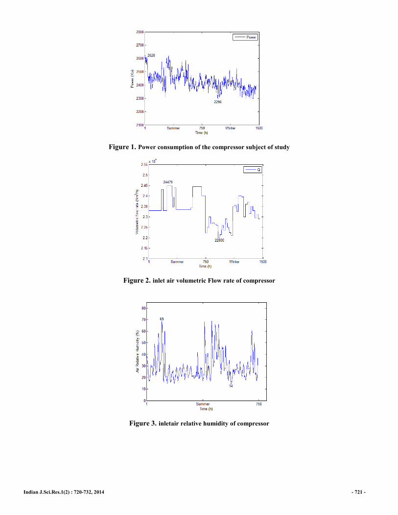
In this study, the thermodynamic behavior of equipment, in
both summer and winter, including the most thermodynamic
ranges, was considered. The minimum and maximum values
for each parameter are indicated on the chart. Consumption
power, inlet air volumetric Flow rate, relative humidity and
inlet air density of the compressor used in this study are shown
in Figures 1, 2, 3 and 4.
Indian J.Sci.Res.1(2) : 720-732, 2014 - 721 -
Figure 1. Power consumption of the compressor subject of study
Figure 2. inlet air volumetric Flow rate of compressor
Figure 3. inletair relative humidity of compressor
Indian J.Sci.Res.1(2) : 720-732, 2014 - 722 -
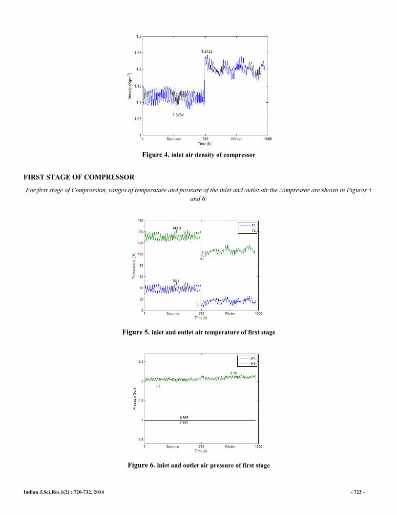
Figure 4. inlet air density of compressor
FIRST STAGE OF COMPRESSOR
For first stage of Compression, ranges of temperature and pressure of the inlet and outlet air the compressor are shown in Figures 5
and 6:
Figure 5. inlet and outlet air temperature of first stage
Figure 6. inlet and outlet air pressure of first stage
Indian J.Sci.Res.1(2) : 720-732, 2014 - 723 -
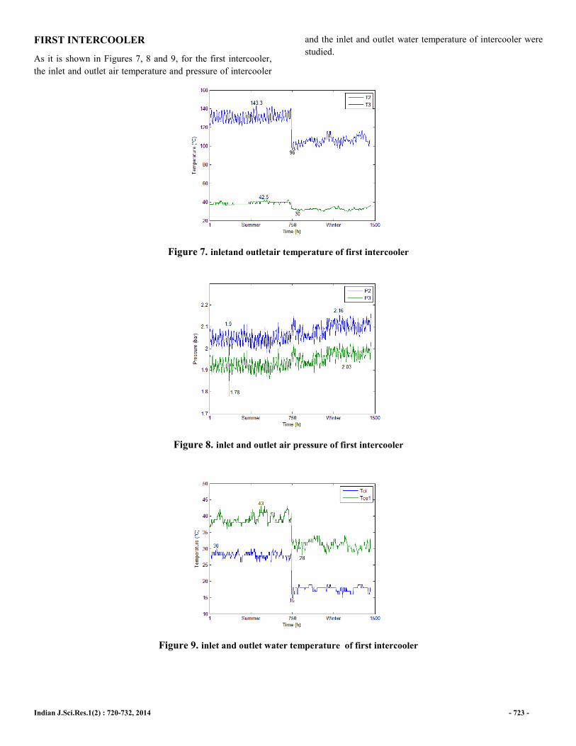
FIRST INTERCOOLER
As it is shown in Figures 7, 8 and 9, for the first intercooler,
the inlet and outlet air temperature and pressure of intercooler
and the inlet and outlet water temperature of intercooler were
studied.
Figure 7. inletand outletair temperature of first intercooler
Figure 8. inlet and outlet air pressure of first intercooler
Figure 9. inlet and outlet water temperature of first intercooler
Indian J.Sci.Res.1(2) : 720-732, 2014 - 724 -
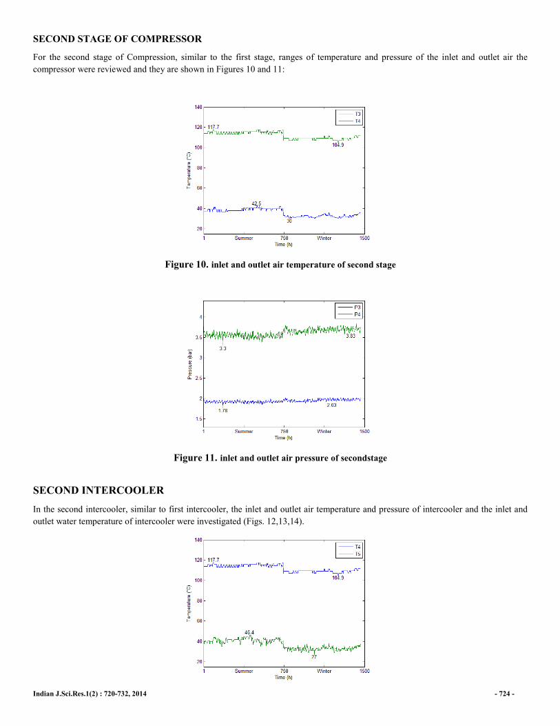
SECOND STAGE OF COMPRESSOR
For the second stage of Compression, similar to the first stage, ranges of temperature and pressure of the inlet and outlet air the
compressor were reviewed and they are shown in Figures 10 and 11:
Figure 10. inlet and outlet air temperature of second stage
Figure 11. inlet and outlet air pressure of secondstage
SECOND INTERCOOLER
In the second intercooler, similar to first intercooler, the inlet and outlet air temperature and pressure of intercooler and the inlet and
outlet water temperature of intercooler were investigated (Figs. 12,13,14).
Indian J.Sci.Res.1(2) : 720-732, 2014 - 725 -
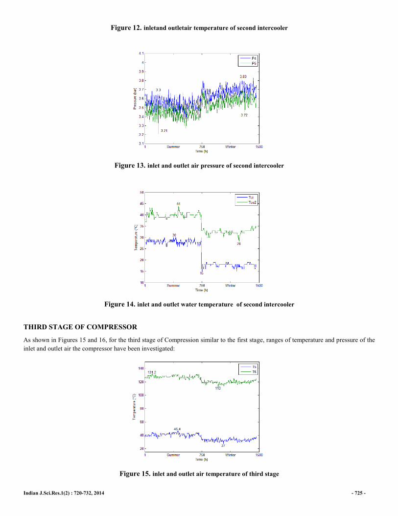
Figure 12. inletand outletair temperature of second intercooler
Figure 13. inlet and outlet air pressure of second intercooler
Figure 14. inlet and outlet water temperature of second intercooler
THIRD STAGE OF COMPRESSOR
As shown in Figures 15 and 16, for the third stage of Compression similar to the first stage, ranges of temperature and pressure of the
inlet and outlet air the compressor have been investigated:
Figure 15. inlet and outlet air temperature of third stage

Indian J.Sci.Res.1(2) : 720-732, 2014 - 726 -
Figure 16. inlet and outlet air pressure of third stage
EQUATION
The governing equations in this study are:
The Governing Equationsof Compression
Thermodynamics rules that used to calculate the power and efficiency of the compressors are independent of the compressor
performance. The compressor can be considered as one control volume by applying these rules. According to first thermodynamics
rule in the compressor, energy equation can be written as relation 1:
(1) m� �h2+ v22
2+gz2� - m� �h1+ v1
2
2+gz1�= q
12+ w12
In the centrifugal compressors, due to small surface of heat transferring, in comparison with other energy terms, the heat transfer can
be neglected in equation (1). Also the terms of the potential difference on both sides of this equation can be neglected. According to
the principle of mass conservation and if we assume that the � � �� �� equals to static enthalpy, then Compression power of a
compressor equals to gradient in the fluid enthalpy from entering to exiting the compressor.
Now, by considering the air as an ideal gas, the enthalpy gradient in an ideal gas is only a function of temperature, the compressor
compression power can be calculated as follows:
� �� ��� � �� � �� ���������� � ������� �� � �2�
It is assumed that the air humidity is constant during the air compression process due to a dryer system which is mounted between the
stages of the compressor. The dryer system can control the air humidity and keep the content of humidity to be within normal range.
On the other hand humidity content of the inlet air of the first stage is similar to second and third stages. Compression power of the
compressor can be calculated regarding to equations 1 & 2 and inlet air temperature of the second and third stages:
(3) ��� �� ���� � ���� �� ������������ � ������������ (4) ��� �� ���� � ���� �� ������������ � ������������
Enthalpy Governing Equation Considering The Effect Of Humidity
In the air, there is always some water vapor. The amount of water vapor in the air is defined by the vapor pressure of the air.Vapor
pressure in the air, cannot be greater than the saturated vapor pressure because in this case, the water must be solid or liquid in air.
Indian J.Sci.Res.1(2) : 720-732, 2014 - 727 -
Relative humidity expresses the relationship between and the pressure of water vapor in the air and the pressure of saturated water
vapor at the same temperature. Relative humidity can be calculated using the following equation 5.
(5) φ ��������′
In order to assess the influence of relative humidity, saturated water vapor should be calculated. In many references approximate
relationship is used to calculate saturated water vapor pressure. To do this, the saturated vapor pressure can be calculated by a
regression exponential correlation for temperature range from 273.16 to 647.14 Kelvin,through Equation 6 in which saturated water
vapor pressure will be calculated in terms of bar.
(6)
����′ ��� � !"# $$%&��'()��('*+)�,(,)�-(,*+)�+(-)�.(/*+�0
� ! 221 �234� 5 6 � � � ! � ! 789:68�;� 3 �9*<=<2> 3 6*<>??6 3� �66*9<66 3� 22*791= 3� �6=*?>?> 3� 6*99=67 As the air is considered as an ideal gas, the water vapor in the air can also be considered as an ideal gas. To calculate the constant
pressure heat capacity of water vapor, the equation 7 is used to establish the 211 �;� @ � @ 6<11�;� temperature range.
(7)
��A��� 3A � 2A��� � BA��� � CA����
3A 6*<197< 2A 69*?29>D � 7 BA 7<*1769D � < CA �22*88>D � 66 The air is considered as a combination of dry and water vapor. Therefore, to calculate the constant pressure heat capacity of air,
constant pressure heat capacity of dry air should also be considered.
(8)
������ 3� � 2���� � B���� � C�����
3� 1*?<2197 2� 67*8>?=D � 7 B� 22*<7<D � < C� �<<*68?=D � 66 To calculate the heat capacity of humid air, mole fraction of water vapor should be calculated. Then heat capacity of humid air is
achieved:
(9) E��� ����� φ����′
�
(10) ����� E�����A � �6 � E�������
Isentropicgoverning Equation
It is assumed that the compressor is a turbo machine; its function can be considered adiabatic. Based on conventionalgoverning
thermodynamic equations the compressor:
Indian J.Sci.Res.1(2) : 720-732, 2014
T1 is the inlet air compressor temperature and T
temperature is calculated from
P1 is the inlet air compressor pressure and P2 is the outlet air
compressor pressure The remarkable thing about the
in the average temperature of inlet and outlet air
compressor is calculated.
MODELING
This modeling is based on by isentropic efficiency Equations
and compression power of each stage. Parameters affecting
isentropic efficiency in a centrifugal compressor are inlet air
temperature, pressure ratio of compression and shaft speed
(Ulf Bossel, 2009).shaft speed is constant and air considered
as an ideal gas, the pressure ratio is related to inlet air
temperature. For thermodynamic modeling of each stage, apart
from the effects of humidity due to its negligible impact
Bossel, 2009), first isentropic efficiency of each compressor is
calculated using related equations by taking specific heat
coefficient at constant pressure in terms of air temperature and
relative humidity of air, and the graph was extracted in terms
of the inlet air temperature to each stage of Compression.
According to the equations, the outlet air temperature of each
Figure 17.
(11)
is the inlet air compressor temperature and T2 is the outlet air compressor temperatures are the same
(12)
is the outlet air
The remarkable thing about the 12 is that
in the average temperature of inlet and outlet air
opic efficiency Equations
and compression power of each stage. Parameters affecting
isentropic efficiency in a centrifugal compressor are inlet air
temperature, pressure ratio of compression and shaft speed
shaft speed is constant and air considered
as an ideal gas, the pressure ratio is related to inlet air
temperature. For thermodynamic modeling of each stage, apart
from the effects of humidity due to its negligible impact (Ulf
ic efficiency of each compressor is
calculated using related equations by taking specific heat
coefficient at constant pressure in terms of air temperature and
relative humidity of air, and the graph was extracted in terms
ach stage of Compression.
According to the equations, the outlet air temperature of each
stage is modeled in terms of isentropic efficiency of that stage,
neural network modeling was performed to study the effect of
the inlet air temperature on pressure ra
Accordingly, Data like temperature and pressure of the inlet
and outlet air of each stage, temperature of inlet and outlet
water of the first and second intercoolers and inlet air
volumetric Flow rate were given to the neural netwo
data and the desired output were obtained from the most
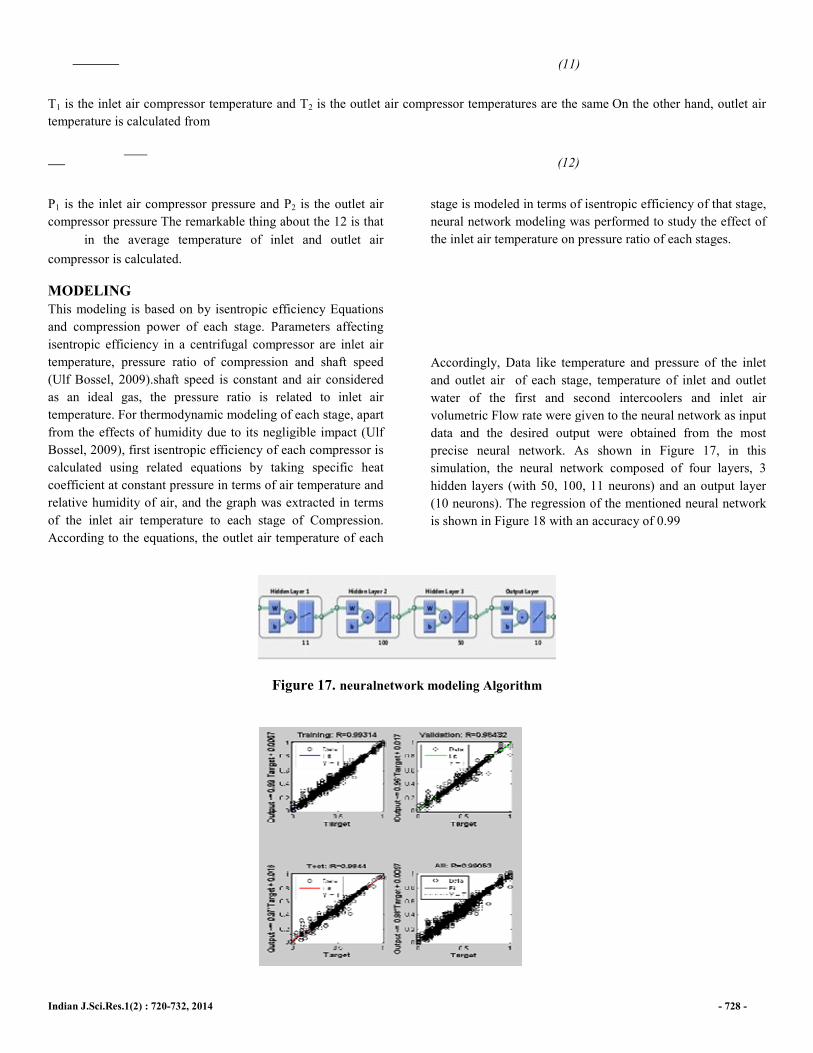
precise neural network. As shown in Figure 17, in this
simulation, the neural network composed of four layers, 3
hidden layers (with 50, 100, 11 neurons) and an output layer
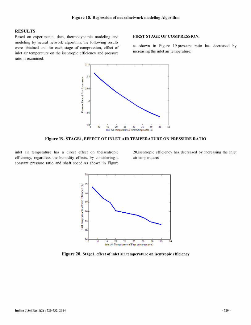
(10 neurons). The regression of the mentioned neural network
is shown in Figure 18 with an accuracy of 0.99
Figure 17. neuralnetwork modeling Algorithm
- 728 -
On the other hand, outlet air
stage is modeled in terms of isentropic efficiency of that stage,
network modeling was performed to study the effect of
inlet air temperature on pressure ratio of each stages.
Accordingly, Data like temperature and pressure of the inlet
and outlet air of each stage, temperature of inlet and outlet
water of the first and second intercoolers and inlet air
volumetric Flow rate were given to the neural network as input
data and the desired output were obtained from the most
precise neural network. As shown in Figure 17, in this
simulation, the neural network composed of four layers, 3
hidden layers (with 50, 100, 11 neurons) and an output layer
The regression of the mentioned neural network
is shown in Figure 18 with an accuracy of 0.99
Indian J.Sci.Res.1(2) : 720-732, 2014
Figure 18. Regression of neuralnetwork modeling Algorithm
RESULTS
Based on experimental data, thermodynamic modeling and
modeling by neural network algorithm, the following results
were obtained and for each stage of compression, effect of
inlet air temperature on the isentropic efficiency and pressure
ratio is examined:
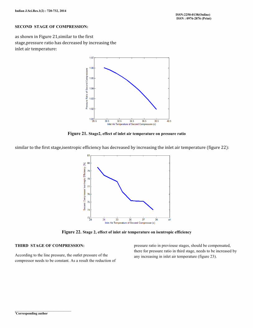
Figure 19. STAGE1, EFFECT OF
inlet air temperature has a direct effect on theisentropic
efficiency, regardless the humidity effects, by considering
constant pressure ratio and shaft speed,As shown in Figure
Figure 20. Stage1, effect of inlet air temperature on
Regression of neuralnetwork modeling Algorithm
on experimental data, thermodynamic modeling and
modeling by neural network algorithm, the following results
and for each stage of compression, effect of
isentropic efficiency and pressure
FIRST STAGE OF COMPRESSION:
as shown in Figure 19 pressure ratio has decreased by
increasing the inlet air temperature
STAGE1, EFFECT OF INLET AIR TEMPERATURE ON PRESSURE RATIO
inlet air temperature has a direct effect on theisentropic
by considering a
,As shown in Figure
20,isentropic efficiency has decreased by increasing the inlet
air temperature:
Stage1, effect of inlet air temperature on isentropic efficiency
- 729 -
FIRST STAGE OF COMPRESSION:
pressure ratio has decreased by
inlet air temperature:
PRESSURE RATIO
20,isentropic efficiency has decreased by increasing the inlet
isentropic efficiency
Indian J.Sci.Res.1(2) : 720-732, 2014
__________________________________ 1Corresponding author
SECOND STAGE OF COMPRESSION:
as shown in Figure 26�similar to the first stage�pressure ratio has decreased by increasing the inlet air temperature:
Figure 21. Stage2, effect of inlet air temperature on pressure ratio
similar to the first stage�isentropic efficiency has decreased by increasing the inlet air temperature �figure 22�:
Figure 22. Stage 2
THIRD STAGE OF COMPRESSION:
According to the line pressure, the outlet pressure of the
compressor needs to be constant. As a result the reduction of
ISSN:2250
ISSN : 0976
increasing the
Stage2, effect of inlet air temperature on pressure ratio
similar to the first stage�isentropic efficiency has decreased by increasing the inlet air temperature �figure 22�:
2, effect of inlet air temperature on isentropic efficiency
According to the line pressure, the outlet pressure of the
As a result the reduction of
pressure ratio in previouse stages, should be compensated,
there for pressure ratio in third stage,
any increasing in inlet air temperature (figure 23).
ISSN:2250-0138(Online)
0976-2876 (Print)
similar to the first stage�isentropic efficiency has decreased by increasing the inlet air temperature �figure 22�:
isentropic efficiency
stages, should be compensated,
in third stage, needs to be increased by
air temperature (figure 23).
Indian J.Sci.Res.1(2) : 720-732, 2014
ISSN:2250-0138(Online)
ISSN : 0976-2876 (Print)
__________________________________ 1Corresponding author
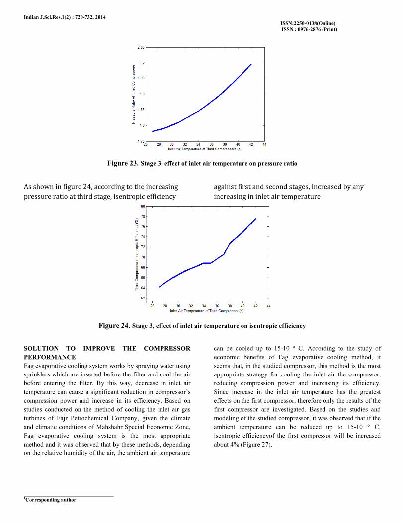
Figure 23. Stage 3, effect of inlet air temperature on pressure ratio
As shown in figure 28� according to the increasing pressure ratio at third stage� isentropic efficiency
against first and second stages� increased by any increasing in inlet air temperature *
Figure 24. Stage 3, effect of inlet air temperature on isentropic efficiency
SOLUTION TO IMPROVE THE COMPRESSOR
PERFORMANCE
Fag evaporative cooling system works by spraying water using
sprinklers which are inserted before the filter and cool the air
before entering the filter. By this way, decrease in inlet air
temperature can cause a significant reduction in compressor’s
compression power and increase in its efficiency. Based on
studies conducted on the method of cooling the inlet air gas
turbines of Fajr Petrochemical Company, given the climate
and climatic conditions of Mahshahr Special Economic Zone,
Fag evaporative cooling system is the most appropriate
method and it was observed that by these methods, depending
on the relative humidity of the air, the ambient air temperature
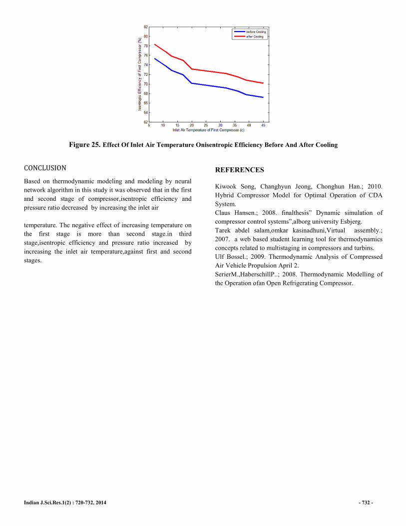
can be cooled up to 15-10 ° C. According to the study of
economic benefits of Fag evaporative cooling method, it
seems that, in the studied compressor, this method is the most
appropriate strategy for cooling the inlet air the compressor,
reducing compression power and increasing its efficiency.
Since increase in the inlet air temperature has the greatest
effects on the first compressor, therefore only the results of the
first compressor are investigated. Based on the studies and
modeling of the studied compressor, it was observed that if the
ambient temperature can be reduced up to 15-10 ° C,
isentropic efficiencyof the first compressor will be increased
about 4% (Figure 27).
Indian J.Sci.Res.1(2) : 720-732, 2014
Figure 25. Effect Of Inlet Air Temperature On
CONCLUSION Based on thermodynamic modeling and modeling by neural
network algorithm in this study it was observed that
and second stage of compressor,isentropic efficiency and
pressure ratio decreased by increasing the inlet air
temperature. The negative effect of increasing temperature on
the first stage is more than second stage.
stage,isentropic efficiency and pressure ratio increased by
increasing the inlet air temperature,against first and second
stages.
t Of Inlet Air Temperature Onisentropic Efficiency Before And After Cooling
Based on thermodynamic modeling and modeling by neural
network algorithm in this study it was observed that in the first
isentropic efficiency and
sing the inlet air
temperature. The negative effect of increasing temperature on
the first stage is more than second stage.in third
nd pressure ratio increased by
increasing the inlet air temperature,against first and second
REFERENCES
Kiwook Song, Changhyun Jeong, Chonghun Han
Hybrid Compressor Model for Optimal Operation of CDA
System.
Claus Hansen.; 2008. finalthesis” Dynamic simulation of
compressor control systems”,alborg university Esbjerg.
Tarek abdel salam,omkar kasinadhuni,Virtual assembly
2007. a web based student learning tool for thermodynamics
concepts related to multistaging in compressors and
Ulf Bossel.; 2009. Thermodynamic Analysis of Compressed
Air Vehicle Propulsion April 2.
SerierM.,HaberschillP..; 2008. Thermodynamic Modelling of
the Operation ofan Open Refrigerating Compressor.
- 732 -
Before And After Cooling
Kiwook Song, Changhyun Jeong, Chonghun Han.; 2010.
Optimal Operation of CDA
hesis” Dynamic simulation of
tems”,alborg university Esbjerg.
Tarek abdel salam,omkar kasinadhuni,Virtual assembly.;
a web based student learning tool for thermodynamics
ing in compressors and turbins.
Thermodynamic Analysis of Compressed
Thermodynamic Modelling of
Open Refrigerating Compressor.